seismic cross-hole survey · 2015-09-03 · seismic cross-hole survey solgeo was founded in 2001 as...
TRANSCRIPT

SEISMIC CROSS-HOLE SURVEY
SOLGEO WAS FOUNDED IN 2001 AS A SPIN-OFF COMPANY FROM ISMES SPA
(ENEL GROUP, LEADER IN THE ITALIAN AND INTERNATIONAL ENERGY MARKET) INHERING ITS GEOPHYSICAL EXPERIENCE.
SOLGEO CAN RELIES ON A TEAM OF TECHNICIANS (MADE BY ELECTRONICS
ENGINEERS, GEOPHYSICISTS, COMPUTER SCIENTISTS AND OTHER EXPERTS) WITH
MORE THAN 25 YEARS’ EXPERIENCE IN THE PLANNING AND EXECUTION OF
GEOPHYSICAL SURVEYS PANORAMA.
SOLGEO CARRIES OUT DEVELOPMENT OF DEVICES FOR DYNAMIC MONITORING OF
LAND, BUILDINGS AND PRODUCTION OF INSTRUMENTS FOR GEOPHYSICAL
RESEARCH.
SOLGEO | - Introduction - 2
V i a P a s t r e n g o 9 , 2 4 0 6 8 S e r i a t e ( B G ) T e l . + 3 9 0 3 5 4 5 2 0 0 7 5 W e b s i t e : w w w . s o l g e o . i t E - m a i l : i n f o @ s o l g e o . i t
- INTRODUCTION -
SOLGEO performs all activities within their own company's Quality System, certified by CSQ/IQNET, and all the operations related to cross hole surveys provide for checks and calibration of equipment and instruments used, before any investigation.
The geophysical survey called “Cross-Hole” consists in the determination of horizontally travelling compression (P) and shear (S) seismic waves at test sites, using two or three boreholes. (ASTM D4428/D4428M-07).
SOLGEO utilizes a set of instruments of its own design and construction allowing to perform measurements quickly and very reliable.
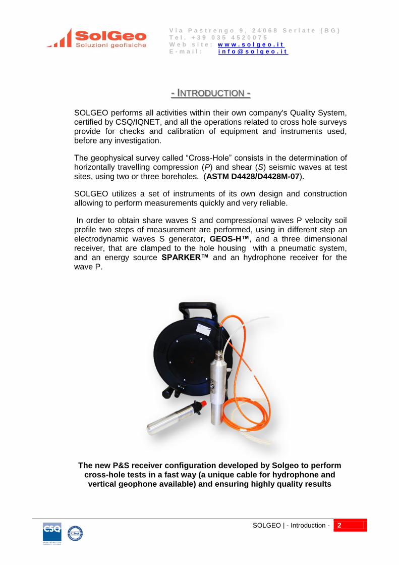
In order to obtain share waves S and compressional waves P velocity soil profile two steps of measurement are performed, using in different step an electrodynamic waves S generator, GEOS-H™, and a three dimensional receiver, that are clamped to the hole housing with a pneumatic system, and an energy source SPARKER™ and an hydrophone receiver for the wave P.
The new P&S receiver configuration developed by Solgeo to perform cross-hole tests in a fast way (a unique cable for hydrophone and vertical geophone available) and ensuring highly quality results

SOLGEO | - Compressional P waves - 3
V i a P a s t r e n g o 9 , 2 4 0 6 8 S e r i a t e ( B G ) T e l . + 3 9 0 3 5 4 5 2 0 0 7 5 W e b s i t e : w w w . s o l g e o . i t E - m a i l : i n f o @ s o l g e o . i t
- COMPRESSIONAL P WAVES -
To generate P waves an automatic energy source, SOLGEO SPARKER™ is used; it can work at many different levels of power (from 100J to 1000J, normally 300J) and it must be used in boreholes filled with water , up to 200 m depth.
Figure 1, 2: Electrodynamics power supply EG&G (from 100 to 1000 J), for P and S waves generation (sx) and new Solgeo Hydrophone
An hydrophone is used as receiver of P waves in a borehole filled with water.
Figure 3: P waves transmitter, SPARKER™ (sx) and its frequency signature (dx) obtained in a sand-lime sequence

SOLGEO | - Shear S waves - 4
V i a P a s t r e n g o 9 , 2 4 0 6 8 S e r i a t e ( B G ) T e l . + 3 9 0 3 5 4 5 2 0 0 7 5 W e b s i t e : w w w . s o l g e o . i t E - m a i l : i n f o @ s o l g e o . i t
- SHEAR S WAVES -
The energy source SOLGEO GEOS-H™ generates automatically polarized waves and it has the possibility to work in boreholes up to 200 m of depth also filled of water. The energy source substantially is composed from two parts; a central section, that contains the pneumatic clamping assembly and second part that contains the electrodynamics waves generator. The device allows to generate alternatively upwards and downwards signals in a simple way, in order to obtain an inversion of the shear waves polarization,. The shear waves arrival can be determinate in a more reliable and precise way.
Figure 4, 5: Electrodynamics transmitter for S waves GEOS-H™ (sx) Geophone receiver ATG-14 (dx) and its relating pneumatic clamping system
A three dimensional receiver, SOLGEO ATG-14™ (Amplified Triaxial Geophone), containing three geophones 14 Hz (one vertical and two horizontal) , with an electronics preamplifier and the possibility of many step of gain is used to receive seismic signals. The clamping to the borehole housing is obtained with a pneumatic device and it is possible to make surveys in boreholes till to 200 m of depth.

SOLGEO | - Acquisition Unit & Software - 5
V i a P a s t r e n g o 9 , 2 4 0 6 8 S e r i a t e ( B G ) T e l . + 3 9 0 3 5 4 5 2 0 0 7 5 W e b s i t e : w w w . s o l g e o . i t E - m a i l : i n f o @ s o l g e o . i t
- ACQUISITION UNIT & SOFTWARE -
The data are recorded with a digital acquisition system by SOLGEO with high sample rate and dynamic more than 110 dB, managed from dedicated software WinCrossHole™. The system allows to complete operations of “averaging” of signal in order to obtain, when necessary, an improvement of the ratio signal/noise. This is possible because the trigger system is perfectly synchronized.
Figure 6, 7: Acquisition unit MiniRec™ and its power supply Battey Box™, designed and produced by Solgeo.
In fact both S and P SOLGEO waves sources have a triggering system electronically controlled, this means that the trigger signal is perfectly constant and delays are always measurable and controllable. For this reason, the equipment used allows you to perform measurements using only two boreholes, thus avoiding the costs of a third hole, while maintaining the reliability of the results in full compliance with ASTM recommendations.
Figure 8, 9: WinCrossHole™ software, by Solgeo, permits to acquire and pick P wave (sx) and S wave first arrival (dx) acquired during acquisition.
SOLGEO | - Inclinometer Survey - 6
V i a P a s t r e n g o 9 , 2 4 0 6 8 S e r i a t e ( B G ) T e l . + 3 9 0 3 5 4 5 2 0 0 7 5 W e b s i t e : w w w . s o l g e o . i t E - m a i l : i n f o @ s o l g e o . i t
- INCLINOMETER SURVEY -
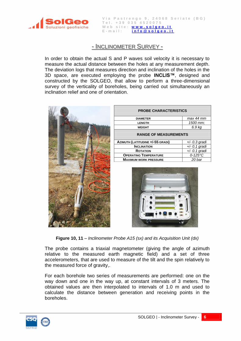
In order to obtain the actual S and P waves soil velocity it is necessary to measure the actual distance between the holes at any measurement depth. The deviation logs that measures direction and inclination of the holes in the 3D space, are executed employing the probe INCLIS™, designed and constructed by the SOLGEO, that allow to perform a three-dimensional survey of the verticality of boreholes, being carried out simultaneously an inclination relief and one of orientation.
Figure 10, 11 – Inclinometer Probe A15 (sx) and its Acquisition Unit (dx)
The probe contains a triaxial magnetometer (giving the angle of azimuth relative to the measured earth magnetic field) and a set of three accelerometers, that are used to measure of the tilt and the spin relatively to the measured force of gravity,.
For each borehole two series of measurements are performed: one on the way down and one in the way up, at constant intervals of 3 meters. The obtained values are then interpolated to intervals of 1.0 m and used to calculate the distance between generation and receiving points in the boreholes.
PROBE CHARACTERISTICS
DIAMETER max 44 mm
LENGTH 1500 mm;
WEIGHT 6.9 kg
RANGE OF MEASUREMENTS
AZIMUTH (LATITUDINE +/-55 GRADI) +/- 0.3 gradi
INCLINATION +/- 0.1 gradi
ROTATION +/- 0.1 gradi
OPERATING TEMPERATURE 0-125°C
MAXIMUM WORK PRESSURE 20 bar

SOLGEO | - Sonic Log Survey - 7
V i a P a s t r e n g o 9 , 2 4 0 6 8 S e r i a t e ( B G ) T e l . + 3 9 0 3 5 4 5 2 0 0 7 5 W e b s i t e : w w w . s o l g e o . i t E - m a i l : i n f o @ s o l g e o . i t
- SONIC LOG SURVEY -
To check if the quality of contact between the holes casing and the soil is good, SOLGEO performs a continuous sonic log into each hole. Signals are reproduced as sonic variable density diagrams (with conventional name of “diagraphy”), which represent the sequence of the sonic signals as a function of time (horizontal axis) and depth (vertical axis).
When the grouting quality between soil and casing is constant, the diagraphies show uniform characteristics; presence of voids or bad contact is readily shown by variations of the recorded signal characteristics.
Figure 12: Sonic logging results (sonic diagraphies); on the left chart in blue line, velocity profile along borehole. In yellow: grouting failure. Sonic probe made by a transmitter and a receiver separated by 1m acoustic isolating material (dx).

SOLGEO | - Sonic Log Survey - 8
V i a P a s t r e n g o 9 , 2 4 0 6 8 S e r i a t e ( B G ) T e l . + 3 9 0 3 5 4 5 2 0 0 7 5 W e b s i t e : w w w . s o l g e o . i t E - m a i l : i n f o @ s o l g e o . i t
Figure 13 – Cross Hole intermediate results. Waterfall plot of recorded seismic traces: signals on the left and P signals on the right.

SOLGEO | - Sonic Log Survey - 9
V i a P a s t r e n g o 9 , 2 4 0 6 8 S e r i a t e ( B G ) T e l . + 3 9 0 3 5 4 5 2 0 0 7 5 W e b s i t e : w w w . s o l g e o . i t E - m a i l : i n f o @ s o l g e o . i t
Figure 14 – Finale Cross Hole results: velocity profile for S waves (sx) and P waves (dx). For each velocity its uncertainty is associated.

SOLGEO | - Sonic Log Survey - 10
V i a P a s t r e n g o 9 , 2 4 0 6 8 S e r i a t e ( B G ) T e l . + 3 9 0 3 5 4 5 2 0 0 7 5 W e b s i t e : w w w . s o l g e o . i t E - m a i l : i n f o @ s o l g e o . i t
MAIN CROSS HOLE SURVEYS CARRIED OUT BY SOLGEO (yrs 2006-2011)
YEAR SITE CLIENT
2006
ABUDHABI – SHOWER TOWER - EAU
Cross-Hole test in n. 1 couples of boreholes (total of 80 m) to determinate the soil characteristics of the SHOWER TOWER foundation.
BAYNUNAH LABORATOR
IES
2007 CROSS-HOLE VALENCIA – SPAIN
N. 4 cross-hole test in n. 4 locations
BUZZI UNICEM
2009-2010
NEW METRO C ROMA - ITALY
Cross-Hole test in n. 23 couples of boreholes (total of 950 m) to evaluate the soil characteristics along the new metro line tunnels.
METROC
2010
CAMPOTOSTO DAM – ITALY
Cross-Hole test in n. 4 couples of boreholes at the bottom of dam to determinate the soil characteristics of foundation.
CESI
2010-2011 PROJECT OF THE NEW BRIDGE “STRETTO DI MESSINA” - ITALY
Cross.Hole test in n. 13 couples of boreholes, at 100m depth
RCT
2010
GIOIOSA JONICA – SS106 – ITALY
Cross hole test in n.4 couples of boreholes from 30 to 60 m depth to evaluate the characteristic of the soil for tunnelling
AR.GI
2010
GARIGLIANO NPP – ITALY
Cross hole test in a couple of boreholes down to 65 m depth. SGI
2011
TUNGABHADRA DAM – INDIA
n. 8 cross-hole tomography test wave P in velocity and attenuation (about 3200 measures) to determinate the homogeneity of the concrete.
AARVEE
2011-2012
ZELAZNY MOST – POLAND
Signed contract to perform n. 10 cross-hole test (530 m total) by means of the ASTM optional method (couples of boreholes). To be executed in October-
November 2011.
MERCUS