sedimentary and tectonic evolution of a trench-slope basin ... · sedimentary and tectonic...
TRANSCRIPT

JOURNAL OF SEDIMENTARY RESEARCH, VOL. 73, NO. 4, JULY, 2003, P. 589–602Copyright q 2003, SEPM (Society for Sedimentary Geology) 1527-1404/03/073-589/$03.00
SEDIMENTARY AND TECTONIC EVOLUTION OF A TRENCH-SLOPE BASIN IN THE NANKAISUBDUCTION ZONE OF SOUTHWEST JAPAN
MICHAEL B. UNDERWOOD,1 GREGORY F. MOORE,2 ASAHIKO TAIRA,3 ADAM KLAUS,4 MOYRA E.J. WILSON,5 CHRISTOPHER L.FERGUSSON,6 SATOSHI HIRANO,7 JOAN STEURER,1 AND THE LEG 190 SHIPBOARD SCIENTIFIC PARTY8
1 Department of Geological Sciences, University of Missouri, Columbia, Missouri 65211e-mail: [email protected]
2 Department of Geology and Geophysics, University of Hawaii, Honolulu, Hawaii 968223 CDEX, Japan Marine Science and Technology Center, Yokosuka, 237–0061, Japan
4 Ocean Drilling Program, Texas A&M University, College Station, Texas 778455 Department of Geological Sciences, University of Durham, Durham, DH1 4EL, U.K.6 School of Geosciences, University of Wollongong, Wollongong, NSW, 2522, Australia
7 IFREE, Japan Marine Science and Technology Center, Yokosuka, 237–0061, Japan8 Keir Becker, University of Miami, Miami, FL; Luann Becker, University of Hawaii, Honolulu, Hawaii; Babette Boeckel, Universitaet Bremen, Bremen, Germany; Barry
Cragg, University of Bristol, Bristol, U.K.; Allison Dean, Western Washington University, Bellingham, Washington; Pierre Henry, Ecole Normale Superieure, Paris,France; Toshio Hisamitsu, University of Tokyo, Tokyo, Japan; Sabine Hunze, Geowissenschaftliche Gemeinschaftsaufgaben—GGA, Hannover, Germany; Miriam
Kastner, Scripps Insitution of Oceanography, La Jolla, California; Alex Maltman, University of Wales, Aberystwyth, U.K.; Julia Morgan, Rice University, Houston,Texas; Yuki Murakami, Hiroshima University, Higashi-Hiroshima, Japan; Demian Saffer, University of Wyoming, Laramie, Wyoming; Mario Sanchez-Gomez,
Universidad de Jaen, Jaen, Spain; Elizabeth Screaton, University of Florida, Gainesville, Florida; David Smith, University of Rhode Island, Narragansett, Rhode Island;Arthur Spivak, University of Rhode Island, Narragansett, Rhode Island; Harold Tobin, New Mexico Institute of Mining and Technology, Socorro, New Mexico; and
Kohtaro Ujiie, National Science Museum, Tokyo, Japan
ABSTRACT: Leg 190 of the Ocean Drilling Program yielded discoveriesabout the early stages of tectonic and sedimentary evolution of atrench-slope basin in the Nankai subduction zone of southwest Japan.Lithofacies character, biostratigraphy, and seismic-reflection datashow that the basin’s architecture was constructed during the earlyQuaternary by frontal offscraping of coarse-grained trench-wedge de-posits. Clast types in muddy gravel beds indicate that one of thetrench’s polymictic sources was enriched in low-grade metasedimen-tary rocks. Outcrops of the Shimanto Belt on the island of Shikokucontain comparable lithologic assemblages, so we suggest that some ofthe turbidity currents and debris flows were funneled from that sourcethrough a transverse canyon–channel system. Offscraped trench de-posits are mildly deformed and nearly flat lying beneath the slope ba-sin. Bedding within the basin laps onto a hanging-wall anticline thatformed above a major out-of-sequence thrust fault. Rapid upliftbrought the substrate above the calcite compensation depth soon afterthe basin was created. The sediment delivery system probably was re-routed during subduction of the Kinan seamounts, thereby isolatingthe juvenile basin from coarse sediment influx. As a consequence, theupper 200 meters of basin fill consist of nannofossil-rich hemipelagicmud with sparse beds of volcanic ash and thin silty turbidites. Intervalsof stratal disruption are also common, and the soft-sediment foldingresulted from north- to northeast-directed gravitational failure. TheNankai accretionary prism has grown 40 km in width during the past1 My, and the slope basin is already filled to its sill point on the sea-ward side. The stratigraphy displays an upward fining and thinningtrend, in contrast to the upward coarsening and thickening mega-se-quences depicted by some conceptual models for slope basins.
INTRODUCTION
Confined turbidite basins can be found in a wide variety of tectonicsettings (Prather et al. 1998; Sinclair and Tomasso 2002). Trench-slopebasins form along all types of subduction margins, even those that expe-rience non-accretion or subduction-erosion (Underwood and Moore 1995).Knowledge of sedimentary successions within such basins is based largelyon interpretations of seismic reflection profiles, which typically show pond-ed sediments trapped behind the tectonic ridges that characterize the un-derlying accretionary prism (G.F. Moore and Karig 1976). We know thatthese environments must adjust to a dynamic interplay between tectonics
and sedimentation, but our ability to document their stratigraphic and struc-tural evolution in detail has been hampered by a lack of ground truth. Leg190 of the Ocean Drilling Program (ODP) included the first attempt to corecontinuously through a modern trench-slope basin into the underlying ac-cretionary prism. The study area is located in the central Nankai forearc,offshore Shikoku, Japan (Fig. 1). Our documentation of tectonostratigraphywithin this active example permits modification of a conceptual frameworkthat was based largely on interpretations of ancient inferred analogues.
Origin of Trench-Slope Basins
In most accretionary subduction margins (e.g., Nankai, Cascadia, Aleu-tians, Sunda, Makran, New Zealand, Barbados), hanging-wall anticlinesform as individual thrust sheets slide over ramps (Boyer and Elliot 1982).Such anticlinal structures create linear bathymetric highs that shape themargin’s structural grain (e.g., Lewis et al. 1988; Davis and Hyndman1989; MacKay et al. 1992). Seismic reflectors within slope basins are usu-ally tilted landward, and their dips become steeper with increasing depthin the basin because of progressive vertical movement of the marginaltectonic ridges (G.F. Moore and Karig 1976). Basins generally increase insurface area upslope as sediment buries extinct tectonic ridges, and thereis a concomitant upslope increase in total sediment thickness (Karig et al.1980; Stevens and Moore 1985). Some stratigraphic successions of thistype reach 3000 m or more in thickness (Davey et al. 1986), but most slopebasins contain less than 1000 m of sediment (Underwood and Moore 1995).
Slope basins change structurally through time in response to progressivesubduction-driven deformation. Combinations of thrusting, folding, and di-apiric intrusion modify the unconformable boundary between slope sedi-ments and the underlying accretionary prism (G.F. Moore and Karig 1976;Scholl et al. 1980; Brown 1990). Larger basins dismember when out-of-sequence reverse, strike-slip, and/or oblique-slip faults propagate throughtheir interiors. Subduction of seamounts also can reshape forearc structuralfabrics on a regional scale and trigger large-scale mass-wasting events (Lal-lemand et al. 1989; Yamazaki and Okamura 1989; Dominguez et al. 2000).The net effect of these processes is to obscure a given basin’s originalthree-dimensional lithofacies and structural architecture.
Facies Model for Trench-Slope Basins
Steeper seafloor gradients on rugged trench slopes promote bypassing ofcoarser sediment and/or erosion by turbidity currents. Most slope apron

590 M.B. UNDERWOOD ET AL.
FIG. 1.—Regional bathymetric map of the Nankai Trough and the northern edge of Shikoku Basin. Numbers refer to sites of the Deep Sea Drilling Project (DSDP) andthe Ocean Drilling Program (ODP). Shaded region along the Muroto Transect corresponds to area of 3-D seismic survey. Bathymetry is in meters. Modified from ShipboardScientific Party (2001e).
deposits are fine grained because they originate via slow hemipelagic set-tling. Strata within trench-slope basins should be thicker and sandier thanthe hemipelagic slope apron because flatter seafloor gradients promote mo-mentum decay and deposition from sediment gravity flows (Komar 1970;Middleton and Hampton 1976). In addition, large bathymetric obstructionsblock or deflect most downslope flow paths (Pantin and Leeder 1987;Kneller et al. 1991; Alexander and Morris 1994). During their early stagesnear the base of slope, direct connections from basins to the shoreline viasubmarine canyons or channels are rare, so the flux of terrigenous sedimenttends to be relatively low. Deposits within these so-called immature slopebasins consist mostly of hemipelagic mud, lutite turbidites, and locallygenerated slides and mudflows (Underwood and Bachman 1982). Distinc-tions are subtle between the immature slope-basin facies and the hemipe-lagic facies of the surrounding slope apron.
Accretionary prism uplift should combine with downslope canyon–chan-nel erosion to increase flux of coarse siliciclastic sediments into slope ba-sins through time (Underwood and Bachman 1982). Once through-goingconduits are established, gravity flows bypass upslope obstructions moreefficiently, thereby increasing rates of sedimentation in the basins by a
factor of ten or more (G.F. Moore and Karig 1976; Underwood and Moore1995). Consequently, stratigraphic evolution of trench-slope basins shouldcreate upward thickening and coarsening mega-sequences (Fig. 2).
Coring of modern trench-slope basin deposits has been meager (e.g.,Kulm et al. 1973; Underwood and Norville 1986). The stratigraphic model(Fig. 2) is actually a conceptual collage that includes interpretations of therock record (e.g., Moore et al. 1980; van der Lingen and Pettinga 1980;George 1992). Such interpretations are seldom straightforward, however,and alternative views have been expressed even for the ‘‘type example’’of Nias Island (e.g., Samuel and Harbury 1996). One dilemma is that lith-ofacies criteria cannot be used to discriminate definitively between accretedtrench-wedge and slope-basin deposits (Underwood and Bachman 1982).Another consideration in such studies is the style of deformation (Smith etal. 1979; Moore and Karig 1980; Moore and Allwardt 1980; Bachman1982; Hibbard et al. 1992). Inferred slope-basin deposits typically displaytight asymmetric folds, mesoscale thrust faults, and evidence of increasingshear towards contacts with more highly deformed melange units inter-preted to be an accretionary prism. The contrast in stratal disruption is nota reliable criterion either, because strain partitioning can occur for a variety

591NANKAI TRENCH-SLOPE BASIN, SW JAPAN
FIG. 2.—Hypothetical model for stratigraphic evolution of a trench-slope basin,based largely on the observations of Moore et al. (1980) on Nias Island, Indonesia.The upward coarsening and thickening megacycle is the result of basin uplift andtemporal increases in terrigenous influx. Smaller-scale cycles are due to progradationor lateral migration of depositional lobes (upward thickening) and migration or aban-donment of channels (upward fining and thinning). Modified from Underwood andMoore (1995).
of reasons within deeper levels of a subduction complex. If, for example,abyssal-plain turbidites enter a subduction zone and underplate by duplex-ing, internal deformation in the domain between the roof and floor thrustswill be minimal (e.g., Sample and Moore 1987). Facies character of un-derplated turbidites, therefore, can be confused with the facies in slope-basin successions (Underwood and Laughland 2001). Perhaps the mostconvincing evidence for slope-basin deposition is an assemblage of fossilsthat indicate intermediate water depths, progressive uplift, and shoaling(e.g., Moore et al. 1980), but such information is not commonly available.
Leg 190 of the Ocean Drilling Program (ODP) provided us with anopportunity to document the early stages of stratigraphic evolution of a
trench-slope basin within the Nankai subduction system of southwest Japan(Fig. 1). We drilled and cored continuously through the basin–prism contactat two sites seaward of the Muroto Peninsula of Shikoku (Holes 1175Aand 1176A). Drilling data from the Muroto study area complement seismicprofiles from a 3-D reflection survey, detailed bathymetry, and side-scansonar (Moore et al. 2001). These data add new complexities to our theoriesregarding subduction-margin sedimentation.
NANKAI TROUGH
Several deep-sea trenches border the Japanese island arc system (Fig. 1).Plate convergence in the Nankai Trough is slightly oblique; youthful oce-anic lithosphere of the Shikoku Basin (Philippine Sea Plate) is subductingat a rate of 2–4 cm/yr (Karig and Angevine 1986; Seno et al. 1993). Riftingof the proto-Izu–Bonin arc and back-arc spreading created the subductingplate (Taylor 1992). Rifting began during the Oligocene, and seafloorspreading in the back-arc basin lasted until ; 15–12 Ma (Chamot-Rookeet al. 1987; Okino et al. 1994). The Kinan seamount chain (Fig. 1) sitsabove the extinct spreading axis (Le Pichon et al. 1987a). Sedimentarydeposits throughout the upper part of the Shikoku Basin consist of hemi-pelagic mudstone and volcanic ash (Pickering et al. 1993). The lower partof the basin, however, changes its facies character considerably alongstrike. Above basement highs associated with the Kinan seamounts, thelower Pliocene and Miocene strata consist predominantly of hemipelagicmudstone and altered vitric mudstone (Taira et al. 1992; Shipboard Sci-entific Party 2001a). Above basement plains (e.g., along the Ashizuri tran-sect), the lower Shikoku Basin facies includes abundant siliciclastic turbi-dites (Shipboard Scientific Party 1975; Pickering et al. 1993; ShipboardScientific Party 2001b).
Water depth along the axis of the Nankai Trough is less than 5,000 m,and the axial gradient dips gently to the southwest (Fig. 1). Rates of sed-iment delivery to the trench are high because of rapid uplift and erosionwithin the main detrital source area: the collision zone between the HonshuArc and the Izu–Bonin Arc (Taira and Niitsuma 1986; Soh et al. 1991;Marsaglia et al. 1992; Underwood et al. 1993). The largest through-goingsediment conduit is Suruga Trough; this submarine canyon extends fromthe shoreline on the west side of the Izu Peninsula and continues along thenorthern flank of Zenisu Ridge into the northeast end of the Nankai Trough(Le Pichon et al. 1987b; Nakamura et al. 1987; Soh et al. 1995). TheNankai deep-sea channel extends from its inception point in Suruga Troughdown the axis of Nankai Trough to a termination point offshore from theKii Peninsula (Shimamura 1989). Fan-shaped sediment mounds occur atthe mouths of Tenryu and Shiono-misaki canyons (Soh et al. 1991), andseveral smaller canyons probably reach the trench (Taira and Ashi 1993).Seismic-reflection records and drilling show that the trench wedge is typ-ically 450 to 700 m thick, and the facies thicken and coarsen upward (J.C.Moore and Karig 1976; Coulbourn 1986; Taira et al. 1992).
The geologic record of subduction-accretion includes onland Creta-ceous–Miocene exposures of the Shimanto Belt (Taira et al. 1988). Thepresent-day Nankai accretionary prism began to form approximately 8–6Ma (Taira et al. 1992). Thrust faults and folds have created a forearc withrugged ridge-and-trough landscape (Le Pichon et al. 1987a, 1987b; Mooreet al. 1991; Ashi and Taira 1992; Morgan et al. 1994; Okino and Kato1995). Several prominent basins on the upper slope (e.g., Muroto and Tosabasins) intercept sediment transport from small canyons and slope gullies(Blum and Okamura 1992). A conspicuous indentation of the structuralgrain near the Muroto Peninsula (Fig. 3) probably was caused by subduc-tion of seamounts associated with the Kinan chain (Yamazaki and Okamura1989; Park et al. 1999; Kodaira et al. 2000).
Geological Context of Leg 190 Sites
Structural architecture of the Nankai accretionary prism varies markedlyalong strike (e.g., Ashi and Taira 1992; Morgan et al. 1994). Bathymetry

592 M.B. UNDERWOOD ET AL.
FIG. 3.—Detailed bathymetric map of the Nankai forearc within the Muroto Transect area. See Figure 1 for regional context. Contour interval is 20 m. Numbers referto ODP drill sites. Shaded region corresponds to area of 3-D seismic survey. Modified from Moore et al. (2000).
is rugged, with irregular ridges and steep scarps (Fig. 3). The Muroto seg-ment (Fig. 1) includes ODP Sites 1175 and 1176. Moore et al. (2001)subdivided the Muroto segment into four structural divisions (Fig. 4). Start-ing at the prism toe, the imbricate-thrust zone is characterized by packagesof seaward-vergent thrust faults, with the frontal thrust forming its seawardedge. A system of out-of-sequence thrusts begins about 20 km landwardof the deformation front. These faults displace older structures that areequivalent to those within the imbricate-thrust zone. The lowermost slope
basin within the Muroto transect is located behind a ridge that was createdby uplift along the frontal out-of-sequence thrust (Fig. 4). The third struc-tural subdivision is called the large-thrust-slice zone, where at least fourdistinctive faults separate previously imbricated packages of relatively co-herent sedimentary strata. Underplating of Shikoku Basin strata may be thecause of strong reflectors beneath the large thrust slices. Slope sedimentsabove the faults are tilted landward, indicating recent uplift. ODP Hole1175A penetrated a second slope basin just landward of a major out-of-

593NANKAI TRENCH-SLOPE BASIN, SW JAPAN
FIG. 4.—Interpretive cross section of the Nankai accretionary prism showing four zones of seismic-reflection structure within the Muroto Transect area (modified fromShipboard Scientific Party 2001e). Numbers refer to ODP drill sites. See Figure 3 for location of 3-D seismic survey, which includes the plane of the cross section.
sequence thrust (Fig. 4), at a water depth of 3012.8 m below sea level.ODP Hole 1176A drilled through a separate fault slice at the seaward edgeof the same basin, at a depth of 3016.8 m below sea level. Farther up slope,the fourth structural zone displays semicontinuous landward-dipping re-flectors beneath a relatively coherent apron of slope sediments.
DRILLING RESULTS
ODP Hole 1175A was cored by APC (advanced hydraulic piston corer)from the mudline to 205.3 mbsf (meters below seafloor) with 99% recov-ery. The extended core barrel (XCB) system was then deployed from 205.3to 445.5 mbsf with 54% recovery. At Site 1176, the APC was used to adepth of 170.6 mbsf with 92% recovery, and the XCB penetrated from170.6 to 449.6 mbsf with 27% recovery. Nannofossils from the cores showthat the age of the underlying Nankai accretionary prism is young (, 4Ma) within our region of interest (Fig. 5). We subdivided the strata intothree lithostratigraphic units: upper slope-basin (unit I), lower slope-basin(unit II), and slope-to-prism transition (unit III). We then attempted tomatch the facies changes with acoustic character and physical properties.Overall, the stratigraphic succession decreases in grain size and bed thick-ness up section (Fig. 5). The following summary is meant to highlight thesalient details of our shipboard descriptions and measurements (ShipboardScientific Party 2001c, 2001d).
Lithostratigraphy
Upper Slope-Basin Facies.—Unit I is Quaternary in age and extendsfrom the seafloor to depths of 224.75 mbsf (Site 1175) and 195.79 mbsf(Site 1176). Hemipelagic mud is the most common lithology within thisupper slope-basin facies (Fig. 6). The silty clay is enriched in calcareousnannofossils. Internal structure of the mud is homogeneous to faintly lam-inated or mottled due to bioturbation. Calcite content within the mud de-posits is due largely to nannofossils. Relative percentages of calcite average23 and 25%. Strata at Site 1175 show a clear increase in carbonate downsection, but the pattern at Site 1176 is more complicated (Fig. 7). Localbeds of volcanic ash vary in thickness from less than a centimeter to overtwo meters. The ash layers typically have sharp, plane-parallel to irregularlower contacts and gradational upper contacts. One unusually thick ash bedoccurs at a depth of 92.7–95.0 mbsf in Hole 1175A. Sand, clayey sand,and silt occur locally as laminae and thin beds with sharp bases, diffusetops, and normal grading (Fig. 6). Most such deposits probably resultedfrom fine-grained turbidity currents. Contorted stratification is the mostnoteworthy aspect of unit I, particularly at Site 1175. Common manifes-
tations of soft-sediment deformation include steeply inclined layers of siltand volcanic ash and small-scale recumbent to inclined folds. Some inter-vals contain curviplanar to irregular fragments of nannofossil-rich mud andash engulfed in a matrix of mud.
Lower Slope-Basin Facies.—Unit II is also Quaternary in age and ex-tends from 224.75 to 301.64 mbsf at Site 1175 and from 195.79 to 223.54mbsf at Site 1176 (Fig. 5). Lithification is more advanced than in unit I,and soft-sediment deformation is absent. The distinguishing lithology ofthe lower slope-basin facies is poorly sorted and structureless sandy mud-stone, whose uppermost occurrence defines the top of unit II. Other lithol-ogies include hemipelagic mudstone, as well as thin beds and laminae ofvolcanic ash and fine sand (Fig. 6). Total carbonate content (from X-raydiffraction) and nannofossil abundance (from smear slides) are generallycomparable to values from the bottom of unit I (Fig. 7).
Slope Basin-to-Prism Transition.—The most characteristic aspect ofunit III, which is Quaternary to Pliocene in age, is its abundance of poorlyindurated, thin- to medium-bedded silt and sand turbidites (Fig. 5). Typicalinternal sedimentary structures include normal size grading, plane-parallellaminae, and ripple cross-laminae (Fig. 6). Grain size varies from verycoarse sand to silt. Lower surfaces are sharp and planar to scoured; uppercontacts are diffuse and gradational. All of these features are consistentwith transport and deposition by turbidity currents. The most exceptionallithology within unit III is muddy gravel to pebbly mud (Fig. 6). Thepebbly mud is poorly sorted throughout. Its clast fabric is disorganized;internal stratification is absent, and clasts are supported partially to com-pletely by a muddy matrix. The matrix is composed of silty clay, similarin composition to the interbeds of hemipelagic mudstone. Clasts are round-ed to subrounded and are up to 5.5 cm in diameter. A polymictic populationof clasts includes abundant quartz, chert, fine-grained sedimentary to me-tasedimentary lithic fragments, and minor fragments of mafic volcanic rock.Beds of hemipelagic mudstone and/or sandy mudstone typically occur be-tween the coarse-grained sand and gravel beds. Relative abundance of cal-cite (largely in the form of micrite cement) decreases sharply within themudstones of unit III; the average value for unit III is 10% at Site 1175and 3% at Site 1176 (Fig. 7).
Biostratigraphy
Calcareous nannofossils provide a continuous record of Pliocene to Ho-locene deposition, and several datums allow us to correlate between thetwo slope-basin sites (Fig. 5). The Pliocene–Pleistocene boundary (1.8 Ma)is located at a depth of 389.27 mbsf in Hole 1175A and at 291.63 mbsf inHole 1176A (Fig. 5). The top of zone NN18 (1.95 Ma) occurs at depths

594 M.B. UNDERWOOD ET AL.
FIG. 5.—Lithostratigraphic and biostratigraphic correlation for Sites 1175 and 1176 of the Ocean Drilling Program, Nankai forearc. Stratigraphic ages (Ma) are based onnannofossil zones (Shipboard Scientific Party 2001c, 2001d).
of 416.77 mbsf (Hole 1175A) and 407.20 mbsf (Hole 1176A). Fossils fromSite 1176 extend to Zone NN15 (3.8 Ma), but the abundance and preser-vation of nannofossils deteriorate markedly within unit III. Calculated ratesof sedimentation (uncorrected for compaction) are highly variable (113 to2859 m/My) within the slope-basin facies (units I and II), although we notethat stratal disruption (described below) distorts the primary depositionalthickness within the upper 200 meters. Rates of sedimentation within unitIII ranged from 10 to 770 m/My.
Structural Geology and Physical Properties
The upper 205 m of Hole 1175A (unit I) are characterized by eightdiscrete zones of core-scale recumbent to isoclinal folds, chaotic mixing oflithologies, and fragmentation of bedding. Between these zones, whichrange from 3 to 10 m in thickness, are intervals with horizontal to gentlyinclined beds. Stratal disruption is comparatively subtle in Hole 1176A,where only two discrete zones were recognized. Fold amplitudes vary froma few centimeters to several meters (inferred from down-core changes inbedding attitudes). Some of the stratal disruption observed in split corecould be an artifact of (or accentuated by) the APC coring process, butexposures of tight fold hinges with sharp and undistorted intersections atthe core margin indicate that most such folds formed through geologicprocesses. Even after using natural remanent magnetism (NRM) declinationto reorient the individual pieces of core (following Shipboard ScientificParty 1991b), we found bedding attitudes to be too scattered to define asystematic trend of dip directions. Axial planes strike west–east to north-
west–southeast and dip to the south and southwest; fold axes trend to thesouthwest with gentle to moderate plunges.
Sediment compaction profiles within the slope-basin successions arecomplicated because of changes in lithology and stratal disruption. Porosityvalues from laboratory measurements of split-core samples are highly var-iable within unit I (Fig. 8). Values in Hole 1175A decrease slightly withdepth from 65–70% at mudline to 61–68% at ; 100 mbsf. Porosity de-creases abruptly at ; 100 mbsf to 57–61% and then decreases graduallyto ; 200 mbsf. Porosity data from Site 1176 decrease from 70–73% atmudline to 55–60% at 200 mbsf. There is also an abrupt shift to lowerporosities at approximately 60 mbsf (Fig. 8).
Most of the cores from units II and III exhibit an unexpectedly smallnumber of mesoscale deformation features. Bedding in Hole 1175A is sub-horizontal from 205 to 445 mbsf, with minor faults and a few localizedzones of disruption. At Site 1176, an interval of high-angle fracturing cross-es the boundary between units II and III, but bedding within unit III islikewise subhorizontal. Units II and III display a uniform compaction gra-dient at Site 1175, with porosity reaching values of less than 45% by 400mbsf (Fig. 8). At Site 1176, in contrast, there is a notable decrease inporosity from 53–57% to 48–54% across the unit II–III boundary. Below350 mbsf, values remain nearly unchanged (40–47%) to the bottom of thehole.
Seismic Stratigraphy
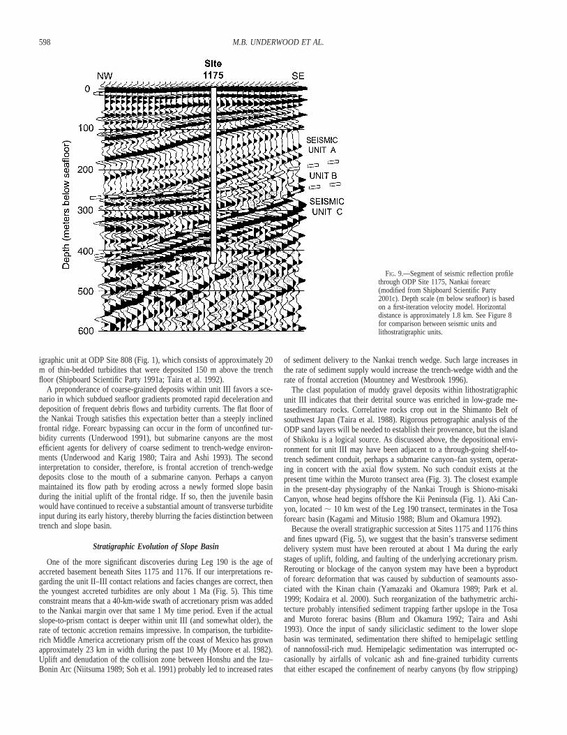
Site 1175.—Seismic reflection units near Site 1175 match reasonablywell with the core-based lithostratigraphy (Fig. 9), in spite of the fact that

595NANKAI TRENCH-SLOPE BASIN, SW JAPAN
FIG. 6.—Examples of lithofacies at the scale of individual cores from ODP Holes 1175A and 1176A, Nankai forearc.

596 M.B. UNDERWOOD ET AL.
FIG. 7.—Relative abundance of calcite and total clay minerals in samples from ODP Holes 1175A and 1176A, Nankai forearc. Mineral abundance is based on X-raydiffraction analysis of random bulk powders (Shipboard Scientific Party 2001c, 2001d).
the velocity structure is not well known. Lithostratigraphic unit I coincideswith seismic unit A; this seismic interval is bounded at the top by theseafloor reflector and at the bottom by an angular discordance. Reflectorsare horizontal near the seafloor and steepen to 8–108 at the base of unit A.The upper 40 m of the depth section display a somewhat irregular anddiscontinuous reflection character, but there is little evidence for the typeof widespread stratal disruption that we observed in the cores. A thick ashbed (. 232 cm at core depth 92.7–95.0 mbsf) may be the cause of anorthwest-dipping high-amplitude positive reflection at approximately 110mbsf seismic depth. If this interpretation is correct, then the velocity–depthmodel needs to be adjusted by at least 15 m to match the lithostratigraphywith acoustic facies.
The upper boundary of seismic unit B (equivalent to lithostratigraphicunit II) occurs at a seismic depth of approximately 250 mbsf (Fig. 9).Reflectors within the upper part of unit B are conformable with the bound-ary. The upper unit boundary dips gently toward the northwest, and down-lap at the base of unit A creates an angular discordance. The base of acous-tic unit B, in contrast, displays onlap toward the southeast. Thus, unit B isa northwest-thickening wedge with relatively continuous and high-ampli-tude internal reflections. The thickness of unit B is roughly 75 m in thevicinity of Site 1175 (Fig. 9), close to the core thickness of unit II (76.89m). Core depth for the unit boundary is 224.75 mbsf, on the basis of thefirst occurrence of sandy mudstone. That change in lithology, however, isnot likely to generate a prominent seismic reflection, and there is no sys-tematic shift in porosity across the lithofacies boundary to account for thecontrast in acoustic impedance (Fig. 8).
Seismic unit C correlates with lithostratigraphic unit III. The upper partof unit C is subparallel to the unit boundary, but its base is ill defined (Fig.9). The core depth of the unit II–III boundary is 301 mbsf, whereas theseismic depth to the unit B–C boundary is approximately 325 mbsf. Ship-board measurements show a decrease in porosity below 325 mbsf (Fig. 8),
and this shift may be a consequence of tectonic consolidation rather thana facies change. We interpret the prominent reflectors below the unit B–Cseismic boundary as thick beds of gravel and pebbly mud that begin atcore depth 340 mbsf. Reflectors within unit C become increasingly irregularand discontinuous below a seismic depth of 400 mbsf (Fig. 9).
Site 1176.—Reflection packages near Site 1176 correlate more closelywith lithostratigraphic boundaries than at Site 1175 (Figs. 8 and 10). Re-flections within the upper 80 m of unit A are generally continuous and dipgently to the southeast (seaward); reflections below a seismic depth of 80mbsf are discontinuous and dip gently landward. Acoustic unit A is wedgeshaped, bounded at the top by the seafloor and at the bottom by a strongcontinuous reflector that dips gently to the northwest. The acoustic bound-ary intersects Hole 1176A at about 180 mbsf, whereas the core depth forthe unit I–II boundary is 195.79 mbsf, on the basis of the first occurrenceof sandy mudstone. As at Site 1175, that lithologic change is not likely tocause a pronounced impedance contrast, so we suspect that the prominentreflector at 180 mbsf seismic depth is related to a partially recovered ashlayer in core 20X (drilled 170.6–180.2 mbsf).
Acoustic unit B correlates crudely with lithostratigraphic unit II. Its low-er boundary is highly irregular and appears as a broad antiformal surfacewith a seismic depth of approximately 230 mbsf near Site 1176. To thenorthwest of Site 1176, strong and continuous reflectors within acousticunit B lap onto this irregular surface and thicken landward (Fig. 10). Re-flectors are discontinuous and decrease in amplitude southeast of Site 1176.
The transition into acoustic unit C (; 230 mbsf) is probably related toan abrupt shift in porosity near the unit II–III boundary (core depth 223.54mbsf). To the northwest of Site 1176, internal reflections within unit C arehigh in amplitude, laterally continuous, and dip to increasingly steep anglestoward land. Reflectors are nearly flat lying near Site 1176, and some rollover to the southeast, thereby defining an antiformal geometry. This largestructure is a fault-bend fold in the hanging wall of an out-of-sequence

597NANKAI TRENCH-SLOPE BASIN, SW JAPAN
FIG. 8.—Variations in porosity with depth inODP Holes 1175A and 1176A, Nankai forearc(Shipboard Scientific Party 2001c, 2001d). Solidlines denote boundaries betweenlithostratigraphic units (see Fig. 5). Dotted linesdenote boundaries between seismic-stratigraphicunits (see Figs. 9 and 10). Also shown are depthranges for APC (advanced hydraulic pistoncorer) and XCB (extended core barrel) coringsystems.
thrust that lies approximately 10–20 m below the base of Hole 1176A (Fig.10).
DISCUSSION
Interpretation of Basin–Prism Boundary
Based on assessments of seismic-reflection and coring data, we place thecontact between the Nankai accretionary prism and overlying slope-basindeposits within a few meters of the core-scale boundary between lithostrat-igraphic units II and III. Pinpointing the location of the boundary is prob-lematic. Core depth and seismic depth of this boundary are within 10 mof one another at Site 1176, but the mismatch is closer to 25 m at Site1175. In addition to possible errors in the velocity model, the mismatch isrooted in our interpretation of two overlapping sets of physical variables.Decreases in porosity within lithologic unit III (Fig. 8) are consistent withhigher amounts of tectonic consolidation within the accretionary prism.Abrupt shifts in physical properties at core depths of ; 325 mbsf and ;225 mbsf are probably responsible for the impedance contrast betweenacoustic units B and C. On the other hand, the changes in grain size andbed thickness toward and across the facies boundary are more gradual (Fig.5). The only sharp change that we noted in composition occurs in calcitecontent, which increases substantially above ; 310 mbsf in Hole 1175Aand above ; 223 mbsf in Hole 1176A (Fig. 7). This increase in carbonatewas probably caused by calcareous nannofossils diluting the supply of sus-pended terrigenous silt and clay. The depositional substrate, which is cur-rently ; 3015 m below sea level, evidently rose above the calcite com-
pensation depth during the early stages of uplift of the frontal accretionaryprism.
Another criterion to consider in evaluating the basin-to-prism boundaryis structural style. In theory, slope-apron and slope-basin deposits shouldbe less deformed than rocks of the underlying accretionary basement (Smithet al. 1979; Moore and Karig 1980; Moore and Allwardt 1980; Bachman1982; Hibbard et al. 1992). In the Nankai example, however, not only arethe accreted strata essentially undeformed at core scale, their beddingplanes are horizontal to subhorizontal. Our explanation for this unexpecteddiscovery is the development of a hanging-wall anticline near Site 1176(Fig. 10). The out-of-sequence thrust fault beneath the anticline displays aramp-to-flat transition immediately beneath Site 1176 (Fig. 10). A similarstructure controls bedding orientation within unit III near Site 1175 (Figs.4 and 9).
Sedimentologic criteria are, likewise, inconclusive as a means of sepa-rating uplifted trench-wedge strata from coarse-grained slope-basin depos-its. The tectono-stratigraphic environment for the upper part of unit IIIremains somewhat ambiguous, so we offer two possible interpretations forthe gradual change in sedimentary facies across the structural transition.The modern Nankai trench wedge receives its turbidite input from a com-bination of axial and transverse flow paths (Taira and Niitsuma 1986; Sohet al. 1991; Pickering et al. 1992; Underwood et al. 1993; Taira and Ashi1993). Some of the thin sand beds within the upper part of unit III mayhave been deposited on the frontal ridge when thicker turbidity currentsmoved across the trench floor and lapped onto the landward wall. Sup-porting evidence for this suggestion comes from the uppermost lithostrat-
598 M.B. UNDERWOOD ET AL.
FIG. 9.—Segment of seismic reflection profilethrough ODP Site 1175, Nankai forearc(modified from Shipboard Scientific Party2001c). Depth scale (m below seafloor) is basedon a first-iteration velocity model. Horizontaldistance is approximately 1.8 km. See Figure 8for comparison between seismic units andlithostratigraphic units.
igraphic unit at ODP Site 808 (Fig. 1), which consists of approximately 20m of thin-bedded turbidites that were deposited 150 m above the trenchfloor (Shipboard Scientific Party 1991a; Taira et al. 1992).
A preponderance of coarse-grained deposits within unit III favors a sce-nario in which subdued seafloor gradients promoted rapid deceleration anddeposition of frequent debris flows and turbidity currents. The flat floor ofthe Nankai Trough satisfies this expectation better than a steeply inclinedfrontal ridge. Forearc bypassing can occur in the form of unconfined tur-bidity currents (Underwood 1991), but submarine canyons are the mostefficient agents for delivery of coarse sediment to trench-wedge environ-ments (Underwood and Karig 1980; Taira and Ashi 1993). The secondinterpretation to consider, therefore, is frontal accretion of trench-wedgedeposits close to the mouth of a submarine canyon. Perhaps a canyonmaintained its flow path by eroding across a newly formed slope basinduring the initial uplift of the frontal ridge. If so, then the juvenile basinwould have continued to receive a substantial amount of transverse turbiditeinput during its early history, thereby blurring the facies distinction betweentrench and slope basin.
Stratigraphic Evolution of Slope Basin
One of the more significant discoveries during Leg 190 is the age ofaccreted basement beneath Sites 1175 and 1176. If our interpretations re-garding the unit II–III contact relations and facies changes are correct, thenthe youngest accreted turbidites are only about 1 Ma (Fig. 5). This timeconstraint means that a 40-km-wide swath of accretionary prism was addedto the Nankai margin over that same 1 My time period. Even if the actualslope-to-prism contact is deeper within unit III (and somewhat older), therate of tectonic accretion remains impressive. In comparison, the turbidite-rich Middle America accretionary prism off the coast of Mexico has grownapproximately 23 km in width during the past 10 My (Moore et al. 1982).Uplift and denudation of the collision zone between Honshu and the Izu–Bonin Arc (Niitsuma 1989; Soh et al. 1991) probably led to increased rates
of sediment delivery to the Nankai trench wedge. Such large increases inthe rate of sediment supply would increase the trench-wedge width and therate of frontal accretion (Mountney and Westbrook 1996).
The clast population of muddy gravel deposits within lithostratigraphicunit III indicates that their detrital source was enriched in low-grade me-tasedimentary rocks. Correlative rocks crop out in the Shimanto Belt ofsouthwest Japan (Taira et al. 1988). Rigorous petrographic analysis of theODP sand layers will be needed to establish their provenance, but the islandof Shikoku is a logical source. As discussed above, the depositional envi-ronment for unit III may have been adjacent to a through-going shelf-to-trench sediment conduit, perhaps a submarine canyon–fan system, operat-ing in concert with the axial flow system. No such conduit exists at thepresent time within the Muroto transect area (Fig. 3). The closest examplein the present-day physiography of the Nankai Trough is Shiono-misakiCanyon, whose head begins offshore the Kii Peninsula (Fig. 1). Aki Can-yon, located ; 10 km west of the Leg 190 transect, terminates in the Tosaforearc basin (Kagami and Mitusio 1988; Blum and Okamura 1992).
Because the overall stratigraphic succession at Sites 1175 and 1176 thinsand fines upward (Fig. 5), we suggest that the basin’s transverse sedimentdelivery system must have been rerouted at about 1 Ma during the earlystages of uplift, folding, and faulting of the underlying accretionary prism.Rerouting or blockage of the canyon system may have been a byproductof forearc deformation that was caused by subduction of seamounts asso-ciated with the Kinan chain (Yamazaki and Okamura 1989; Park et al.1999; Kodaira et al. 2000). Such reorganization of the bathymetric archi-tecture probably intensified sediment trapping farther upslope in the Tosaand Muroto forerac basins (Blum and Okamura 1992; Taira and Ashi1993). Once the input of sandy siliciclastic sediment to the lower slopebasin was terminated, sedimentation there shifted to hemipelagic settlingof nannofossil-rich mud. Hemipelagic sedimentation was interrupted oc-casionally by airfalls of volcanic ash and fine-grained turbidity currentsthat either escaped the confinement of nearby canyons (by flow stripping)

599NANKAI TRENCH-SLOPE BASIN, SW JAPAN
FIG. 10.—Segment of seismic reflection profile through ODP Site 1176, Nankai forearc (modified from Shipboard Scientific Party 2001d). Depth scale (m below seafloor)is based on a first-iteration velocity model. Horizontal distance is approximately 3.1 km. See Figure 8 for comparison between seismic units and lithostratigraphic units.
or flowed over or around surrounding bathymetric obstructions (e.g., Muckand Underwood 1990; Underwood 1991; Alexander and Morris 1994). Dis-tinctive sandy mud layers in unit II probably originated as relatively fine-grained debris flows or mudflows, with the sand-size clasts fully supportedby the muddy matrix. Transport could have occurred within transient chan-nels or as unconfined flows. The higher concentration of calcareous nan-nofossils in the hemipelagic mud of units I and II supports the idea ofuplift and deposition on a basin substrate that was elevated above the calcitecompensation depth. Deposition of mud continued until the basin was filledto its seaward sill point.
The overall pattern of facies change within the Nankai slope basin (Fig.5) matches part, but not all, of a conceptual model that is based largely onthe rock exposures of Nias Island (Fig. 2). One important point to considerduring such comparisons is the tendency of confined turbidite basins toevolve through several discrete stages. Some such basins, for example, passthough successive phases of structural birth, flow ponding, flow stripping,flow bypass (due either to channel incision or abandonment), and blanket-ing or backfilling (Prather et al. 1998; Sinclair and Tomasso 2002). Thisso-called ‘‘fill-and-spill’’ behavior can lead to upward thinning and finingtrends during the abandonment phase. We also stress, however, that therecord of sedimentation documented at Sites 1175 and 1176 spans a rela-tively brief timeframe of 1 My or less. The basin is still in its adolescent
stage of development, with 300 m or less of total sediment accumulation.The current water depth of the basin floor is approximately 3000 m. Incomparison, the Nias Beds exceed 3000 m in total thickness, and the upperturbidites are overlain unconformably by a coral reef cap (Moore et al.1980). As we project several million years into the future, the Nankai slopebasin will shoal in response to continued underplating. Downslope erosionof transverse channels should increase the influx of coarse-grained turbi-dites, as shown by Blum and Okamura (1992) for the present-day uppertrench slope. Thus, the full evolutionary cycle of the basin could still resultin the predicted upward-coarsening mega-trend.
Stratal Disruption within Upper Slope-Basin Facies
The relatively thin intervals of chaotic stratification within unit I evi-dently were created by local remobilization of hemipelagic sediment as theslope basin filled to capacity. According to one classification scheme formass movements (Martinsen 1994), the types of core-scale features that weencountered span a continuum from slump (coherent mass with consider-able internal deformation) to debris flow (remolded mass with plastic be-havior). According to other widely used classifications, however, the term‘‘slump’’ connotes rotation of bedding above a curved failure surface asopposed to a translational slide above a planar surface (e.g., Prior and

600 M.B. UNDERWOOD ET AL.
Coleman 1984). There is little evidence of internal deformation at the scaledepicted by seismic-reflection profiles, and no hint of block rotation abovediscrete failure surfaces (Figs. 9, 10). Thus, the exact forms of slope failureremain ambiguous.
Remobilization of muddy slope deposits is a common phenomenon with-in subduction zones. The severity of slope failure ranges from sluggishdownslope creep of hemipelagic mud (Baltuck et al. 1985) to prodigiousslumps and slides that are capable of generating tsunamis (von Huene etal. 1989). Material recycling will occur if the failure surface excavates deepbeneath the slope apron (Moore et al. 1976; Jacobi 1984; Ballance 1991).Slope failure is particularly common along the frontal ridge on the lowerslope, where associated debris lobes typically extend onto the trench floor(e.g., Davis and Hyndman 1989; Ashi and Taira 1992). Likely triggeringmechanisms for intraformational mass wasting include dynamic loading byseismic waves, the intrinsic weakness of porous mud on steep slopes, andoversteepening of bedding planes during episodes of uplift (Hampton et al.1996).
We suggest that the products of mass wasting within unit I are a responseto episodic back-tilting of the slope basin. Site 1175 was subjected to atleast eight failure events over a time span of approximately 0.5 My. Site1176 was not affected as frequently or as severely because of its relativelyflat-lying bathymetric character at the seaward edge of the slope basin.Gravity-driven slip probably was triggered by repeated uplift of the basin’ssoutheastern margin during displacement along the two out-of-sequencethrusts that shape the basin’s architecture (Fig. 10). Apparent dips of fan-ning reflectors within seismic unit A are generally toward the northwest.Axial planes of core-scale folds dip to the south and southwest (i.e., in thedirection opposite to downslope movement). The chances of future occur-rences of slope failure are minimal unless the basin’s marginal relief ex-periences tectonic rejuvenation.
CONCLUSIONS
High rates of sedimentation within the Nankai Trough create favorableconditions for rapid frontal accretion. Shipboard data from Leg 190 of theOcean Drilling Program show that the accretionary wedge has grown morethan 40 km in width during the past 1 My. Numerous intraslope basinshave formed above the Nankai accretionary prism. The sedimentary tran-sition from slope-basin deposits to the underlying accreted turbidites cannotbe defined precisely at Site 1175 or 1176 because their facies characterchanges gradually across the tectono-stratigraphic transition. Initial upliftof a frontal ridge evidently occurred in close proximity to the mouth of asubmarine canyon. The seaward margin of the slope basin was sustainedby fault-bend folding (ramp-to-flat transition) in the hanging wall of anout-of-sequence thrust. Because of this structural geometry, strata beneaththe slope basin maintain low angles of dip and relatively mild degrees ofdeformation. The basin’s overall stratigraphic succession thins and finesupward. We believe that sediment delivery paths to the slope basin werererouted when subduction of the Kinan seamounts caused widespread dam-age across the Muroto forearc. Once the basin was isolated from its sourceof coarse siliciclastic sediment, turbidite sedimentation was replaced byhemipelagic settling. Uplift, landward tilting, and subhorizontal rotation ofthe seaward marginal ridge during the past 0.5 My triggered at least eightepisodes of north- to northeast-directed mass wasting. The ridge has sincebeen buried to its seaward sill point. Our opportunity to document thisexample of subduction-margin sedimentation has led to some importantlessons for interpretation of inferred analogues in the rock record. Contacts,facies changes, and structural styles are not always as expected. Modernsystems of this type are dynamic and unpredictable enough to warrantcaution when applying generic conceptual models to interpretations of therock record.
ACKNOWLEDGMENTS
We thank Captain Tom Ribbens, the crew, and technicians aboard JOIDES Res-olution for their dedicated assistance during ODP Leg 190. This research used sam-ples provided by the Ocean Drilling Program, sponsored by the U.S. National Sci-ence Foundation and participating countries under management of Joint Oceano-graphic Institutions, Inc. Thoughtful reviews by K. Pickering, R. Hiscott, and K.Marsaglia improved both the form and substance of the manuscript.
REFERENCES
ALEXANDER, J., AND MORRIS, S., 1994, Observations on experimental, nonchannelized, high-concentration turbidity currents and variations in deposits around obstacles: Journal of Sed-imentary Research, v. A64, p. 899–909.
ASHI, J., AND TAIRA, A., 1992, Structure of the Nankai accretionary prism as revealed fromIZANAGI sidescan imagery and multichannel seismic reflection profiling: The Island Arc,v. 1, p. 104–115.
BACHMAN, S.B., 1982, The Coastal Belt of the Franciscan: youngest phase of northern Cali-fornia subduction, in Leggett, J.K., ed., Trench-Forearc Geology: Geological Society ofLondon, Special Publication 10, p. 401–418.
BALLANCE, P.F., 1991, Gravity flows and rock recycling on the Tonga landward trench slope:relation to trench-slope tectonic processes: Journal of Geology, v. 99, p. 817–828.
BALTUCK, M., VON HUENE, R., AND ARNOTT, R.J., 1985, Sedimentology of the western continentalslope of Central America, in von Huene, R., and Aubouin, J., eds., Initial Reports of theDeep Sea Drilling Project, v. 84: Washington, D.C., U.S. Government Printing Office, p.921–937.
BLUM, P., AND OKAMURA, Y., 1992, Pre-Holocene sediment dispersal systems and effects ofstructural controls and Holocene sea-level rise from acoustic facies analysis; SW Japanforearc: Marine Geology, v. 108, p. 295–322.
BOYER, S.E., AND ELLIOT, D., 1982, Thrust systems: American Association of Petroleum Ge-ologists, Bulletin, v. 66, p. 1196–1230.
BROWN, K.M., 1990, The nature and hydrologic significance of mud diapirs and diatremes foraccretionary systems: Journal of Geophysical Research, v. 95, p. 8969–8982.
CHAMOT-ROOKE, N., RENARD, V., AND LE PICHON, X., 1987, Magnetic anomalies in the ShikokuBasin: a new interpretation: Earth and Planetary Science Letters, v. 83, p. 214–228.
COULBOURN, W.T., 1986, Sedimentologic summary, Nankai Trough Sites 582 and 583, andJapan Trench Site 584, in Kagami, H., Karig, D.E., and Coulbourn, W.T., eds., InitialReports of the Deep Sea Drilling Project, v. 87: Washington, D.C., U.S. Government Print-ing Office, p. 909–926.
DAVEY, F.J., HAMPTON, M., CHILDS, J., FISHER, M.A., LEWIS, K., AND PETTINGA, J.R., 1986, Struc-ture of a growing accretionary prism, Hikurangi margin, New Zealand: Geology, v. 14, p.663–666.
DAVIS, E.E., AND HYNDMAN, R.D., 1989, Accretion and recent deformation of sediments alongthe northern Cascadia subduction zone: Geological Society of America, Bulletin, v. 101, p.1465–1480.
DOMINGUEZ, S., MALAVIELLE, J., AND LALLEMAND, S.E., 2000, Deformation of accretionary wedgesin response to seamount subduction: Insights from sandbox experiments: Tectonics, v. 19,p. 182–196.
GEORGE, A.D., 1992, Deposition and deformation of an Early Cretaceous trench-slope basindeposit, Torlesse terrane, New Zealand: Geological Society of America, Bulletin, v. 104, p.570–580.
HAMPTON, M.A., LEE, H.J., AND LOCAT, J., 1996, Submarine landslides: Reviews of Geophysics,v. 34, p. 33–59.
HIBBARD, J.P., KARIG, D.E., AND TAIRA, A., 1992, Anomalous structural evolution of the Shi-manto accretionary prism at Murotomisaki, Shikoku Island, Japan: The Island Arc, v. 1, p.133–147.
JACOBI, R.D., 1984, Modern submarine sediment slides and their implications for melange andthe Dunnage Formation in north-central Newfoundland, in Raymond, L.A., ed., Melanges:Their Nature, Origin, and Significance: Geological Society of America, Special Paper 198,p. 81–102.
KAGAMI, H., AND MITUSIO, T., 1988, The Aki Canyon Fault—A boundary of the earthquakesource area: Kochi University, Usa Marine Biological Institute, Reports, v. 10, p. 15–27.
KARIG, D.E., AND ANGEVINE, C.L., 1986, Geologic constraints on subduction rates in the NankaiTrough, in Kagami, H., Karig, D.E., and Coulbourn, W.T., eds., Initial Reports of the DeepSea Drilling Project, v. 87: Washington, D.C., U.S. Government Printing Office, p. 789–796.
KARIG, D.E., MOORE, G.F., CURRAY, J.R., AND LAWRENCE, M.B., 1980, Morphology and shallowstructure of the lower trench slope off Nias Island, Sunda arc, in Hayes, D.E., ed., TheTectonic and Geologic Evolution of Southeast Asian Seas and Islands: American Geophys-ical Union, Monograph 23, p. 179–208.
KNELLER, B., EDWARDS, D., MCCAFFREY, W., AND MOORE, R., 1991, Oblique reflection of tur-bidity currents: Geology, v. 14, p. 250–252.
KODAIRA, S., TAKAHASHI, N., PARK, J., MOCHIZUKI, K., SHINOHARA, M., AND KIMURA, S., 2000,Western Nankai Trough seismogenic zone: Results from a wide-angle ocean bottom seismicsurvey: Journal of Geophysical Research, v. 105, p. 5887–5905.
KOMAR, P.D., 1970, The competence of turbidity current flow: Geological Society of America,Bulletin, v. 81, p. 1555–1562.
KULM, L.D., VON HUENE, R., AND THE SHIPBOARD SCIENTIFIC PARTY, 1973, Initial Reports of the DeepSea Drilling Project, v. 18: Washington, D.C., U.S. Government Printing Office, 1,077 p.
LALLEMAND, S., CULOTTA, R., AND VON HUENE, R., 1989, Subduction of the Daiichi KashimaSeamount in the Japan Trench: Tectonophysics, v. 160, p. 231–247.

601NANKAI TRENCH-SLOPE BASIN, SW JAPAN
LE PICHON, X., IIYAMA, J.T., CHAMLEY, H., CHARVET, J., FAURE, M., FUJIMOTO, H., FURUTA, T.,IDA, Y., KAGAMI, H., LALLEMANT, S., LEGGETT, J., MURUTA, A., OKADA, H., RANGIN, C., RENARD,V., TAIRA, A., AND TOKUYAMA, H., 1987a, Nankai trough and the fossil Shikoku Ridge: resultsof box 6 Kaiko survey: Earth and Planetary Science Letters, v. 83, p. 186–198.
LE PICHON, X., IIYAMA, T., CHAMLEY, H., CHARVET, J., FAURE, M., FUJIMOTO, H., FURUTA, T., IDA,Y., KAGAMI, H., LALLEMENT, S., LEGGETT, J., MURATA, A., OKADA, H., RANGIN, C., RENARD,V., TAIRA, A., AND TOKUYAMA, H., 1987b, The eastern and western ends of Nankai Trough:results of box 5 and box 7 Kaiko survey: Earth and Planetary Science Letters, v. 83, p.199–213.
LEWIS, S.D., LADD, J.W., AND BRUNS, T.R., 1988, Structural development of an accretionaryprism by thrust and strike-slip faulting: Shumagin region, Aleutian Trench: Geological So-ciety of America, Bulletin, v. 100, p. 767–782.
MACKAY, M.E., MOORE, G.F., COCHRANE, G.R., MOORE, J.C., AND KULM, L.D., 1992, Landwardvergence and oblique structural trends in the Oregon margin accretionary prism: implicationsand effect on fluid flow: Earth and Planetary Science Letters, v. 109, p. 477–491.
MARSAGLIA, K.M., INGERSOLL, R.V., AND PACKER, B., 1992, Tectonic evolution of the JapaneseIslands as reflected in modal compositions of Cenozoic forearc and backarc sand and sand-stone: Tectonics, v. 11, p. 1028–1043.
MARTINSEN, O., 1994, Mass movement, in Maltman, A., ed., The Geological Deformation ofSediments: London, Chapman & Hall, p. 127–165.
MIDDLETON, G.V., AND HAMPTON, M.A., 1976, Subaqueous sediment transport and depositionby sediment gravity flows, in Stanley, D.J., and Swift, D.J.P., eds., Marine Sediment Trans-port and Environmental Management: New York, John Wiley, p. 197–218.
MOORE, D.G., CURRAY, J.R., AND EMMEL, F.J., 1976, Large submarine slide (olistostrome) as-sociated with Sunda Arc subduction zone, northeast Indian Ocean: Marine Geology, v. 21,p. 211–226.
MOORE, G.F., AND KARIG, D.E., 1976, Development of sedimentary basins on the lower trenchslope: Geology, v. 4, p. 693–697.
MOORE, G.F., AND KARIG, D.E., 1980, Structural geology of Nias Island, Indonesia: implicationsfor subduction zone tectonics: American Journal of Science, v. 280, p. 193–223.
MOORE, G.F., BILLMAN, H.G., HEHANUSSA, P.E., AND KARIG, D.E., 1980, Sedimentology andpaleobathymetry of Neogene trench-slope deposits, Nias Island, Indonesia: Journal of Ge-ology, v. 88, p. 161–180.
MOORE, G.F., KARIG, D.E., SHIPLEY, T.H., TAIRA, A., STOFFA, P.L., AND WOOD, W.T., 1991,Structural framework of the ODP Leg 131 area, Nankai Trough, in Taira, A., Hill, I.A.,Firth, J.V., et al., Proceedings of the Ocean Drilling Program, Initial Reports, v. 131: CollegeStation, Ocean Drilling Program, p. 15–20.
MOORE, G.F., TAIRA, A., BALDAUF, J., AND KLAUS, A., 2000, Deformation and fluid flow pro-cesses in the Nankai Trough accretionary prism: Ocean Drilling Program, Leg 190 ScientificProspectus, online http://www-odp.tamu.edu/publications/prosp/190pprs/190toc.html.
MOORE, G.F., TAIRA, A., BANGS, N.L., KURAMOTO, S., SHIPLEY, T.H., ALEX, C.M., GULICK, S.S.,HILLS, D.J., IKE, T., ITO, S., LESLIE, S.C., MCCUTCHEON, A.J., MOCHIZUKI, K., MORITA, S.,NAKAMURA, Y., PARK, J.-O., TAYLOR, B.L., TOYAMA, G., YAGI, H., AND ZHAO, Z., 2001, DataReport: Structural setting of the Leg 190 Muroto Transect, in Moore, G.F., Taira, A., Klaus,A., et al., Proceedings of the Ocean Drilling Program, Initial Reports, v. 190: CollegeStation, Texas (Ocean Drilling Program), online http://www-odp.tamu.edu/publications/190pIR/190ir.htm.
MOORE, J.C., AND KARIG, D.E., 1976, Sedimentology, structural geology, and tectonics of theShikoku subduction zone, southwestern Japan: Geological Society of America, Bulletin, v.87, p. 1259–1268.
MOORE, J.C., AND ALLWARDT, A., 1980, Progressive deformation of a Tertiary trench slope,Kodiak Islands, Alaska: Journal of Geophysical Research, v. 85, p. 4741–4756.
MOORE, J.C., WATKINS, J.S., SHIPLEY, T.H., MCMILLEN, K.J., BACHMAN, S.B., AND LUNDBERG, N.,1982, Geologic and tectonic evolution of a juvenile accretionary terrane along a truncatedconvergent margin: Synthesis of results from Leg 66 of the Deep Sea Drilling Project,southern Mexico: Geological Society of America Bulletin, v. 93, p. 847–861.
MORGAN, J.K., KARIG, D.E., AND MANIATTY, A., 1994, The estimation of diffuse strains in thetoe of the western Nankai accretionary prism: A kinematic solution: Journal of GeophysicalResearch, v. 99, p. 7019–7032.
MOUNTNEY, N.P., AND WESTBROOK, G.K., 1996, Modeling sedimentation in ocean trenches: theNankai Trough from 1 Ma to the present: Basin Research, v. 8, p. 85–101.
MUCK, M.M., AND UNDERWOOD, M.B., 1990, Upslope flow of turbidity currents: a comparisonamong field observations, theory, and laboratory models: Geology, v. 18, p. 54–57.
NAKAMURA, K., RENARD, V., ANGELIER, J., AZEMA, J., BOURGOIS, J., DEPLUS, C., FUJIOKA, K.,HAMANO, Y., HUCHON, P., KINOSHITA, H., LABAUME, P., OGAWA, Y., SENO, T., TAKEUCHI, A.,TANAHASHI, M., UCHIYAMA, A., AND VIGNERESSE, J.-L., 1987, Oblique and near collision sub-duction, Sagami and Suruga Troughs—preliminary results of the French–Japanese 1984Kaiko cruise, Leg 2: Earth and Planetary Science Letters, v. 83, p. 229–242.
NIITSUMA N., 1989, Collision tectonics in the Southern Fossa Magna, Central Japan: ModernGeology, v. 14, p. 3–18.
OKINO, K., AND KATO, Y., 1995, Geomorphological study on a clastic accretionary prism: theNankai Trough: The Island Arc, v. 4, p.182–198.
OKINO, K., SHIMAKAWA, Y., AND NAGAOKA, S., 1994, Evolution of the Shikoku Basin: Journalof Geomagnetics and Geoelectricity, v. 46, p. 463–479.
PANTIN, H.M., AND LEEDER, M.R., 1987, Reverse flow in turbidity currents: the role of internalsolitons: Sedimentology, v. 34, p. 1143–1155.
PARK, J.-O., TSURU, T., KANEDA, Y., KONO, Y., KODAIRA, S., TAKAHASHI, N., AND KINOSHITA, H.,1999, A subducting seamount beneath the Nankai accretionary prism off Shikoku, southwestJapan: Geophysical Research Letters, v. 26, p. 931–934.
PICKERING, K.T., UNDERWOOD, M.B., AND TAIRA, A., 1992, Open-ocean to trench turbidity-currentflow in the Nankai Trough: Flow collapse and reflection: Geology, v. 20, p. 1009–1102.
PICKERING, K.T., UNDERWOOD, M.B., AND TAIRA, A., 1993, Stratigraphic synthesis of the DSDP–
ODP sites in the Shikoku Basin and Nankai Trough and accretionary prism, in Hill, I., Taira,A., Firth, J., and Vrolijk, P., eds., Proceedings of the Ocean Drilling Program, ScientificResults, v. 131: College Station, Ocean Drilling Program, p. 313–330.
PRATHER, B.E., BOOTH, J.R., STEFFENS, G.S., AND CRAIG, P.A., 1998, Classification, lithologiccalibration, and stratigraphic succession of seismic facies of intraslope basins, deep-waterGulf of Mexico: American Association of Petroleum Geologists, Bulletin, v. 82, p. 701–728.
PRIOR, D.B., AND COLEMAN, J.M., 1984, Submarine slope instability, in Brunsden, D., and Prior,D.B., eds., Slope Instability: New York, John Wiley & Sons, p. 419–455.
SAMUEL, M.A., AND HARBURY, N.A., 1996, The Mentawai fault zone and deformation of theSumatran forearc in the Nias area, in Hall, R., and Blundell, D., eds., Tectonic Evolutionof Southeast Asia: Geological Society of London, Special Publication 106, p. 337–351.
SAMPLE, J.C., AND MOORE, J.C., 1987, Structural style and kinematics of an underplated slatebelt, Kodiak and adjacent islands, Alaska: Geological Society of America, Bulletin, v. 99,p. 7–20.
SCHOLL, D.W., VON HUENE, R., VALLIER, T.L., AND HOWELL, D.G., 1980, Sedimentary massesand concepts about tectonic processes at underthrust ocean margins: Geology, v. 8, p. 564–568.
SENO, T., STEIN, S., AND GRIPP, A.E., 1993, A model for the motion of the Philippine Sea Plateconsistent with NUVEL-1 and geological data: Journal of Geophysical Research, v. 98, p.17,941–17,948.
SHIMAMURA, K., 1989, Topography and sedimentary facies of the Nankai Deep Sea Channel,in Taira, A., and Masuda, F., eds., Sedimentary Facies in the Active Plate Margin: Tokyo,Terra Scientific Publishing Company, p. 529–556.
SHIPBOARD SCIENTIFIC PARTY, 1975, Site 297, in Karig, D.E., Ingle, J.C., Jr., et al., Initial Reportsof the Deep Sea Drilling Project, v. 31: Washington, D.C., U.S. Government Printing Office,p. 275–316.
SHIPBOARD SCIENTIFIC PARTY, 1991a, Site 808, in Taira, A., Hill, I., Firth, J.V., et al., Proceedingsof Ocean Drilling Program, Initial Reports, v. 131: College Station, Texas, Ocean DrillingProgram, p. 71–269.
SHIPBOARD SCIENTIFIC PARTY, 1991b, Explanatory notes, in Taira, A., Hill, I., Firth, J.V., et al.,Proceedings of the Ocean Drilling Program, Initial Reports, v. 131: College Station, Texas,Ocean Drilling Program, p. 25–60.
SHIPBOARD SCIENTIFIC PARTY, 2001a, Site 1173, in Moore, G.F., Taira, A., Klaus, A., et al.,Proceedings of the Ocean Drilling Program, Initial Reports, v. 190: College Station, Texas,Ocean Drilling Program, online http://www-odp.tamu.edu/publications/190pIR/190ir.htm.
SHIPBOARD SCIENTIFIC PARTY, 2001b, Site 1177, in Moore, G.F., Taira, A., Klaus, A., et al.,Proceedings of the Ocean Drilling Program, Initial Reports, v. 190: College Station, Texas,Ocean Drilling Program, online http://www-odp.tamu.edu/publications/190pIR/190ir.htm.
SHIPBOARD SCIENTIFIC PARTY, 2001c, Site 1175, in Moore, G.F., Taira, A., Klaus, A., et al.,Proceedings of the Ocean Drilling Program, Initial Reports, v. 190: College Station, Texas,Ocean Drilling Program, online http://www-odp.tamu.edu/publications/190pIR/190ir.htm.
SHIPBOARD SCIENTIFIC PARTY, 2001d, Site 1176, in Moore, G.F., Taira, A., Klaus, A., et al.,Proceedings of the Ocean Drilling Program, Initial Reports, v. 190: College Station, Texas,Ocean Drilling Program, online http://www-odp.tamu.edu/publications/190pIR/190ir.htm.
SHIPBOARD SCIENTIFIC PARTY, 2001e, Leg 190 summary, in Moore, G.F., Taira, A., Klaus, A.,et al., Proceedings of the Ocean Drilling Program, Initial Reports, v. 190: College Station,Texas, Ocean Drilling Program, online http://www-odp.tamu.edu/publications/190pIR/190ir.htm.
SINCLAIR, H.D., AND TOMASSO, M., 2002, Depositional evolution of confined turbidite basins:Journal of Sedimentary Research, v. 72, p. 451–456.
SMITH, G.W., HOWELL, D.G., AND INGERSOLL, R.V., 1979, Late Cretaceous trench-slope basinsof central California: Geology, v. 7, p. 303–306.
SOH, W., PICKERING, K.T., TAIRA, A., AND TOKUYAMA, H., 1991, Basin evolution in the arc–arcIzu Collision Zone, Mio–Pliocene Miura Group, central Japan: Geological Society of Lon-don, Journal, v. 148, p. 317–330.
SOH, W., TANAKA, T., AND TAIRA, A., 1995, Geomorphology and sedimentary processes of amodern slope-type fan delta (Fujikawa fan delta), Suruga Trough, Japan: Sedimentary Ge-ology, v. 98, p. 79–95.
STEVENS, S.H., AND MOORE, G.F., 1985, Deformational and sedimentary processes in trenchslope basins of the western Sunda Arc, Indonesia: Marine Geology, v. 69, p. 93–112.
TAIRA, A., AND ASHI, J., 1993, Sedimentary facies evolution of the Nankai forearc and itsimplications for the growth of the Shimanto accretionary prism, in Hill, I.A., Taira. A.,Firth, J.V., et al., Proceedings of the Ocean Drilling Program, Scientific Results, v. 131:College Station, Texas, Ocean Drilling Program, p. 331–341.
TAIRA, A., AND NIITSUMA, N., 1986, Turbidite sedimentation in the Nankai Trough as interpretedfrom magnetic fabric, grain size, and detrital modal analyses, in Kagami, H., Karig, D.E.,and Coulbourn, W.T., eds., Initial Reports of the Deep Sea Drilling Project, v. 87: Wash-ington, D.C., U.S. Government Printing Office, p. 611–632.
TAIRA, A., KATTO, J., TASHIRO, M., OKAMURA, M., AND KODAMA, K., 1988, The Shimanto Beltin Shikoku, Japan—evolution of Cretaceous to Miocene accretionary prism: Modern Geol-ogy, v. 12, p. 5–46.
TAIRA, A., HILL, I., FIRTH, J., BERNER, U., BRUCKMANN, W., BYRNE, T., CHABERNAUD, T., FISHER,A., FOUCHER, J.-P., GAMO, T., GIESKES, J., HYNDMAN, R., KARIG, D., KASTNER, M., KATO, Y.,LALLEMENT, S., LU, R., MALTMAN, A., MOORE, G., MORAN, K., OLAFFSON, G., OWENS, W.,PICKERING, K., SIENA, F., TAYLOR, E., UNDERWOOD, M., WILKINSON, C., YAMANO, M., AND ZHANG,J., 1992, Sediment deformation and hydrogeology of the Nankai Trough accretionary prism:synthesis of shipboard results of ODP Leg 131: Earth and Planetary Science Letters, v. 109,p. 431–450.
TAYLOR, B., 1992, Rifting and the volcanic-tectonic evolution of the Izu–Bonin–Mariana Arc,in Taylor, B., Fujioka, K., et al., Proceedings of the Ocean Drilling Program, ScientificResults, v. 126: College Station, Texas, Ocean Drilling Program, p. 625–651.

602 M.B. UNDERWOOD ET AL.
UNDERWOOD, M.B., 1991, Submarine canyons, unconfined turbidity currents, and sedimentarybypassing of forearc regions: Critical Reviews in Aquatic Sciences, v. 4, p. 149–200.
UNDERWOOD, M.B., AND BACHMAN, S.B., 1982, Sedimentary facies associations within subduc-tion complexes, in Leggett, J.K., ed., Trench-Forearc Geology: Geological Society of Lon-don, Special Publication 10, p. 537–550.
UNDERWOOD, M.B., AND KARIG, D.E., 1980, Role of submarine canyons in trench and trench-slope sedimentation: Geology, v. 8, p. 432–436.
UNDERWOOD, M.B., AND NORVILLE, C.R., 1986, Deposition of sand in a trench-slope basin byunconfined turbidity currents: Marine Geology, v. 71, p. 383–392.
UNDERWOOD, M.B., AND MOORE, G.F., 1995, Trenches and trench-slope basins, in Busby, C.J.,and Ingersoll, R.V., eds., Tectonics of Sedimentary Basins: Cambridge, MA, BlackwellScience, p. 179–219.
UNDERWOOD, M.B., AND LAUGHLAND, M.M., 2001, Paleothermal structure of the Point San Luisslab of central California: Effects of Late Cretaceous underplating, out-of-sequence thrusting,and late Cenozoic dextral offset: Tectonics, v. 20, p. 97–111.
UNDERWOOD, M.B., ORR, R., PICKERING, K., AND TAIRA, A., 1993, Provenance and dispersalpatterns of sediments in the turbidite wedge of Nankai Trough, in Hill, I.A., Taira, A., Firth,J.V., et al., Proceedings of the Ocean Drilling Program, Scientific Results, v. 131: CollegeStation, Texas, Ocean Drilling Program, p. 15–34.
VAN DER LINGEN, G.J., AND PETTINGA, J.R., 1980, The Makara Basin: a Miocene slope-basinalong the New Zealand sector of the Australian–Pacific obliquely convergent plate boundary,in Ballance, P.F., and Reading, H.G., eds., Sedimentation in Oblique-Slip Mobile Zones:International Association of Sedimentologists, Special Publication 4, p. 191–215.
VON HUENE, R., BOURGEOIS, J., MILLER, J., AND PAUTOT, G., 1989, A large tsunamogenic landslideand debris flow along the Peru Trench: Journal of Geophysical Research, v. 94, p. 1703–1714.
YAMAZAKI, T., AND OKAMURA, Y., 1989, Subducting seamounts and deformation of overridingforearc wedges around Japan: Tectonophysics, v. 160, p. 207–229.
Received 8 August 2001; accepted 20 September 2002.