securing wide area measurement systems (980.29 kb)
TRANSCRIPT

PNNL-17116
Securing Wide Area Measurement Systems M.D. Hadley J.B. McBride T.W. Edgar L.R. O’Neil J.D. Johnson June 2007 Prepared for U.S. Department of Energy Office of Electricity Delivery and Energy Reliability under Contract DE-AC05-76RL01830

DISCLAIMER This report was prepared as an account of work sponsored by an agency of the United States Government. Neither the United States Government nor any agency thereof, nor Battelle Memorial Institute, nor any of their employees, makes any warranty, express or implied, or assumes any legal liability or responsibility for the accuracy, completeness, or usefulness of any information, apparatus, product, or process disclosed, or represents that its use would not infringe privately owned rights. Reference herein to any specific commercial product, process, or service by trade name, trademark, manufacturer, or otherwise does not necessarily constitute or imply its endorsement, recommendation, or favoring by the United States Government or any agency thereof, or Battelle Memorial Institute. The views and opinions of authors expressed herein do not necessarily state or reflect those of the United States Government or any agency thereof.
PACIFIC NORTHWEST NATIONAL LABORATORY operated by BATTELLE
for the UNITED STATES DEPARTMENT OF ENERGY
under Contract DE-AC05-76RL01830
This document was printed on recycled paper.
Securing Wide Area Measurement Systems M.D. Hadley J.B. McBride T.W. Edgar L.R. O’Neil R.D. Johnson June 2007
Prepared for the U.S. Department of Energy Office of Electricity Delivery and Energy reliability Under Contract DE-AC05-76RL01830 Pacific Northwest National Laboratory Richland, Washington 99352
iii
Executive Summary This report documents an assessment of wide area measurement system (WAMS) security conducted by Pacific Northwest National Laboratory (PNNL) as a project funded by the National SCADA Test Bed Program in cooperation with the Department of Energy’s Transmission Reliability Program. With emphasis on cyber security, this report also addresses other categories of risk and vulnerability including equipment reliability, data quality and human performance. Collectively, these issues affect the overall security of currently functional WAMS infrastructure and its projected future evolution. This effort is motivated by the growing importance of information security in current WAMS operations, as well as the full range of security considerations that must be addressed to enable the projected expansion of its applications. Currently, a WAMS consists of advanced measurement technology, information tools, and operational infrastructure that enable the planning, operation and management of large and complex electric power systems. In its present form, it is used typically as a standalone infrastructure that complements the grid’s conventional supervisory control and data acquisition (SCADA) system. In this role, the WAMS is expressly designed to enhance the operator’s real-time "situational awareness", which is necessary for safe and reliable grid operation in addition to supporting post-event analysis of significant system disturbances. In the future, developing WAMS technologies are expected to be become integrated into the real-time control system of the grid. Because of the current significance and potential future criticality of WAMS infrastructure, its security and reliability have become high priority issues. As the major focus of this study, cyber security addresses the protection of cyber-based systems that comprise the WAMS critical infrastructures of both public and private organizations. When applied to a WAMS, cyber security is seen not as an end product but rather a building block upon which a reliable WAMS infrastructure can be built and operated. The report summarizes an analysis of WAMS security concerns based on the description of a generic WAMS model to identify significant threat scenarios. Currently operating WAMS environments were studied to provide implementation-specific information that contributed to the identification of appropriate safeguards. Thus, this assessment reviews WAMS vulnerabilities in the context of actual system implementations and recommends research and development to minimize the operational impact of these threats. The data provided to a control center by a WAMS network is similar to SCADA data; message availability and integrity are the primary security objectives. As WAMS data are incorporated into real-time grid control applications, measures that ensure the message itself can be explicitly trusted become increasingly important. This study concludes that further research is needed to address vulnerabilities associated with the dependence of the synchro-phasor time stamp on the global positioning system (GPS), the robustness of phasor measurement unit (PMU) hardware and software, and the ability of a phasor data concentrator (PDC) to handle a concentrated cyber attack.
iv
Acknowledgements The authors extend their gratitude to Ken Martin, Bonneville Power Administration, and Ritchie Carroll, Tennessee Valley Authority, for their time and sharing of operational knowledge of wide area measurement systems. Their contributions to this report are greatly appreciated. The authors also are grateful to Jeff Dagle, John DeSteese, and John Hauer (Laboratory Fellow), Pacific Northwest National Laboratory for reviewing draft versions of this document and for providing valuable feedback. The final document is enhanced as a result of their comments.

v
Glossary
3DES Triple Data Encryption Standard ACA Australian Communication Authority AES Advanced encryption standard AMR Automated meter reading ATM Asynchronous transfer mode BGP Border gateway protocol BPA Bonneville Power Administration C/A Course/acquisition CCMP Counter mode with cipher block chaining messaging authentication code
protocol CCN Control center network CDMA Code division multiple access CIP Critical infrastructure protection COM Component object model COO Continuity of operations CPE Customer-premises equipment CRC Cyclical redundancy check DAC Double attached concentrator DAS Dual attachment station DCOM Distributed component object model DOE-OE Department of Energy, Office of Electricity Delivery and Energy
Reliability DOS Denial of service DOT Department of Transportation DTLS Datagram transport layer security as defined in RFC 4347 EAP Extensible authentication protocol EM Electro-magnetic EMS Energy management system EPRI Electric Power Research Institute ETSI European Telecommunications Standards Institute FCC Federal Communications Commission FDDI Fiber distributed data interface FEP Front end processors GPS Global positioning system HMAC Keyed-hash message authentication code HTTP Hyper text transfer protocol ID Identity IEC International Electrotechnical Commission IED Intelligent electronic device IEEE Institute of Electrical and Electronics Engineers IP Internet protocol IPSEC IP security as defined in RFCs 4301–4309 ISC Intrinsically secure computing

ISP Internet service provider IT Information technology LAN Local area network LED Light emitting diodes MAC Media access control MAS Multiple address system MPLS Multi-protocol label switching NERC North American Electric Reliability Corporation NIST National Institute of Standards and Technology NSA National Security Agency NTP Network time protocol OLE Object linking and embedding OPC OLE for process control OSI Open Systems Interconnection Basic Reference Model OSPF Open shortest path first PDC Phasor data concentrator PKI Public key infrastructure PMK Pair-wise master key PMU Phasor measurement unit PNNL Pacific Northwest National Laboratory RF Radio frequency RIP Routing information protocol RTU Remote terminal unit SA Situational awareness SAC Single attached concentrator SAS Single-attachment station SCADA Supervisory control and data acquisition SHF Super-high frequency SOAP Simple object access protocol SOC Second-of-the-century SONET Synchronous optical network TLS Transport layer security UA OPC United Architecture UDP User datagram protocol as defined in RFC 768 UHF Ultra-high frequency UTC Coordinated universal time VAT Vulnerability assessment team VPN Virtual private network WAMS Wide area measurement system WAPA Western Area Power Administration WECC Western Electricity Coordinating Council WiMax Worldwide interoperability for microwave access WSCC Western Systems Coordinating Council XML Extensible markup language XOR Exclusive Or
Contents
Executive Summary ........................................................................................................... iii Acknowledgements............................................................................................................ iv Glossary .............................................................................................................................. v Introduction......................................................................................................................... 1 Wide Area Measurement System Security ......................................................................... 2 WAMS Network Implementations ..................................................................................... 6 Reliance on External Time Source ..................................................................................... 8 Configuration Management ................................................................................................ 9 Cyber Defense and Response............................................................................................ 10 Limited Situational Awareness ......................................................................................... 12 Implicit Trust .................................................................................................................... 13 Protocol Use and Limitations............................................................................................ 14
Phasor Streaming Protocols .......................................................................................... 15 Institute of Electrical & Electronics Engineers (IEEE) Standard 1344 .................... 15 PDCStream ............................................................................................................... 15 PDCxchng ................................................................................................................. 16 IEEE Standard C37.118............................................................................................ 16 Security Considerations ............................................................................................ 17
Archival and Analysis Protocols................................................................................... 18 IEEE Standard C37.111-1999 (COMTRADE)......................................................... 18 Object Linking and Embedding (OLE) for Process Control (OPC) ......................... 19 Security Considerations ............................................................................................ 20
Communication Infrastructure .......................................................................................... 21 Present Communication Infrastructure ......................................................................... 21
Serial Communication .............................................................................................. 21 Analog Microwave.................................................................................................... 21 Virtual Private Networks .......................................................................................... 23
Communication Infrastructure Trends.......................................................................... 23 Fiber Optics............................................................................................................... 24 Licensed Digital Microwave..................................................................................... 28 Private Broadband (WiMax, IEEE 802.16) .............................................................. 30 Multiple Address System Radio ............................................................................... 32
Continuity of Operations................................................................................................... 35 Maintenance.................................................................................................................. 35 Disaster Recovery ......................................................................................................... 36
Equipment Reliability ....................................................................................................... 37 Data Integrity .................................................................................................................... 40 Human Error Behavior...................................................................................................... 41 Security Summary............................................................................................................. 42 Conclusions....................................................................................................................... 43 References......................................................................................................................... 44
viii
Figures
Figure 1. Flow of multi-source data within an integrated WAMS network ...................... 2 Figure 2. Isolated WAMS communication network ......................................................... 6 Figure 3. WAMS with an isolated communication network and out-bound | data interface....................................................................................................................... 7 Figure 4. Fully integrated WAMS communication network ............................................. 7 Figure 5. Technology elements for networking PMUs to a PDC using GPS.................... 8 Figure 6. Intrinsically secure computing concept ............................................................ 10 Figure 7. Locations of protocol use in a generic WAMS network .................................. 14 Figure 8. Example of PMUs recording the same system disturbance differently ........... 38
Tables
Table 1. WAMS Vulnerabilities ........................................................................................ 3 Table 2. WAMS Strengths................................................................................................. 5
1
Introduction A wide area measurement system (WAMS) consists of advanced measurement technology, information tools, and operational infrastructure that facilitate the understanding and management of the increasingly complex behavior exhibited by large power systems. In its present form, a WAMS may be used as a stand-alone infrastructure that complements the grid’s conventional supervisory control and data acquisition (SCADA) system. As a complementary system, a WAMS is expressly designed to enhance the operator’s real-time "situational awareness" that is necessary for safe and reliable grid operation. In the future, WAMS technologies are expected to be incrementally incorporated into the actual control system of the grid. Because of the current significance and potential future criticality of WAMS infrastructure, its security and reliability have become high priority issues. The Department of Energy’s Transmission Reliability Program, administered by its Office of Electricity Delivery and Energy Reliability (DOE-OE), is supporting the research, deployment, and demonstration of various WAMS technologies to enhance the reliability of the Nation’s electrical power grid. The present study of WAMS security being conducted by Pacific Northwest National Laboratory (PNNL) is a project funded by the DOE-OE National SCADA Test Bed Program, in cooperation with the Transmission Reliability Program. This report is the companion to “Descriptive Model of a Generic WAMS” (Hauer and DeSteese 2007), which provides a generic WAMS model description. This reference is a principal basis for the security assessment presented in this document.
The term “security” has different definitions in the area of control systems, which are dependent upon context. In the past, security has been defined as the ability of the electric grid to remain operational following local and system wide transients. However, in the current security conscious climate generated by the events of September 11, 2001, and with the increasing convergence of control system technology with information technology (IT), the definition has embraced information protection as well as reliability. The principal focus of this report is cyber security. As used here, cyber security addresses the protection of cyber-based systems that comprise the WAMS critical infrastructures of both public and private organizations. When applied to a WAMS, cyber security is not an end product but rather a building block upon which a reliable WAMS infrastructure can be built and operated. Other categories of risk are also addressed including equipment reliability, data quality and human performance that affect the overall security of WAMS. All security vulnerabilities escalate in importance as WAMS transitions from its present function as basically a back-up information system into its anticipated future role of becoming an integral component of an energy management system (EMS) that provides real-time grid control and protection. This effort has been motivated by the growing importance of information security in current WAMS operations, as well as security considerations relating to the foreseen expansion of its applications.
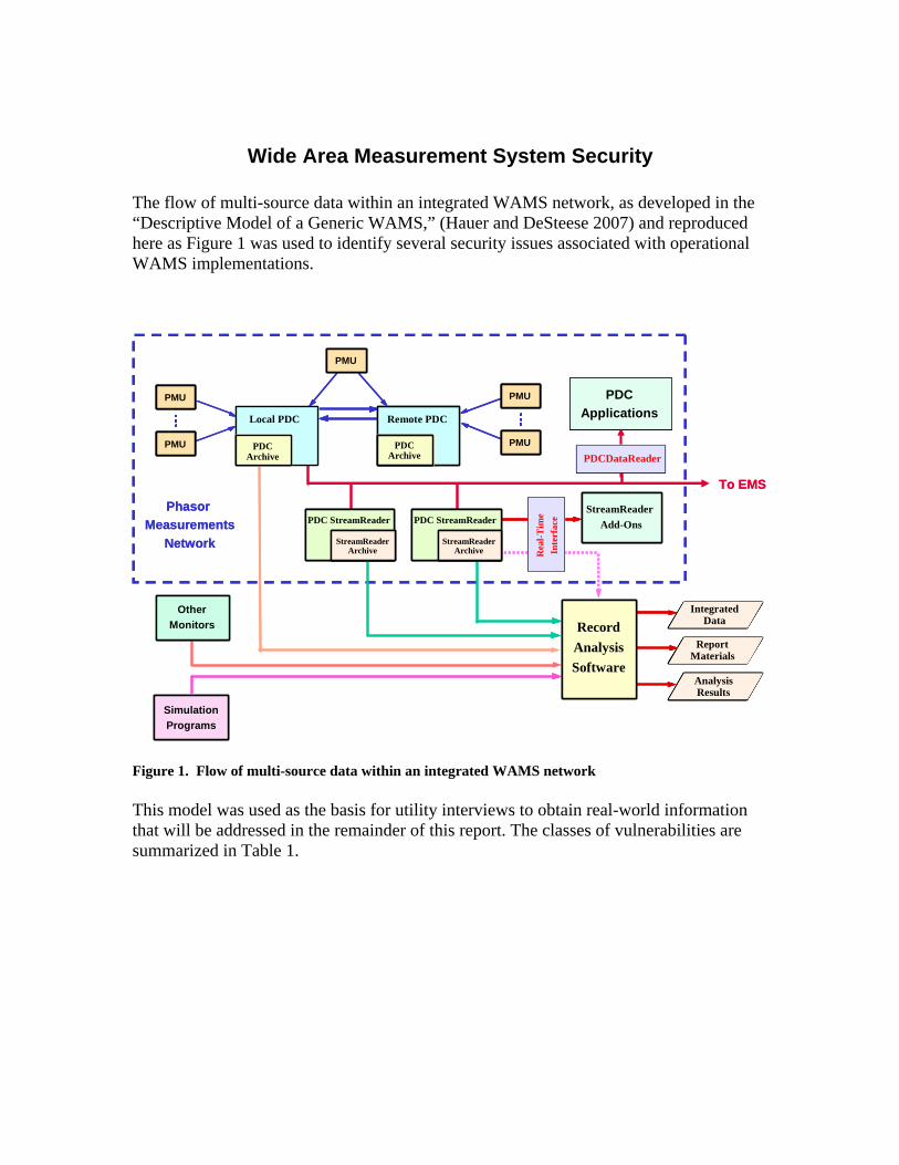
Wide Area Measurement System Security The flow of multi-source data within an integrated WAMS network, as developed in the “Descriptive Model of a Generic WAMS,” (Hauer and DeSteese 2007) and reproduced here as Figure 1 was used to identify several security issues associated with operational WAMS implementations.
Phasor Measurements
Network
StreamReader Add-Ons
Rea
l-Tim
eIn
terf
ace
SimulationPrograms
OtherMonitors
To EMS
RecordAnalysisSoftware
PMUPMU
PMUPMU
PMUPMU
PMUPMU
PMUPMU
PDCApplications
PDCDataReader
IntegratedData
ReportMaterials
AnalysisResults
PDCArchive
PDCArchive
Local PDC Remote PDC
PDC StreamReader
StreamReaderArchive
PDC StreamReader
StreamReaderArchive
Phasor Measurements
Network
StreamReader Add-Ons
Rea
l-Tim
eIn
terf
ace
SimulationPrograms
OtherMonitors
To EMS
RecordAnalysisSoftware
PMUPMU
PMUPMU
PMUPMUPMUPMU
PMUPMUPMUPMU
PMUPMU
PMUPMU
PMUPMUPMUPMU
PMUPMUPMUPMU
PMUPMUPMUPMU
PDCApplications
PDCApplications
PDCDataReaderPDCDataReader
IntegratedData
ReportMaterials
AnalysisResults
IntegratedData
ReportMaterials
AnalysisResults
IntegratedData
ReportMaterials
AnalysisResults
PDCArchive
PDCArchive
PDCArchive
PDCArchive
Local PDC Remote PDC
PDC StreamReader
StreamReaderArchive
PDC StreamReader
StreamReaderArchive
StreamReaderArchive
PDC StreamReader
StreamReaderArchive
PDC StreamReader
StreamReaderArchive
StreamReaderArchive
Figure 1. Flow of multi-source data within an integrated WAMS network This model was used as the basis for utility interviews to obtain real-world information that will be addressed in the remainder of this report. The classes of vulnerabilities are summarized in Table 1.
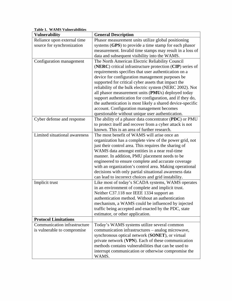
Table 1. WAMS Vulnerabilities Vulnerability General Description Reliance upon external time source for synchronization
Phasor measurement units utilize global positioning systems (GPS) to provide a time stamp for each phasor measurement. Invalid time stamps may result in a loss of data and subsequent visibility into the WAMS.
Configuration management The North American Electric Reliability Council (NERC) critical infrastructure protection (CIP) series of requirements specifies that user authentication on a device for configuration management purposes be supported for critical cyber assets that impact the reliability of the bulk electric system (NERC 2002). Not all phasor measurement units (PMUs) deployed today support authentication for configuration, and if they do, the authentication is most likely a shared device-specific account. Configuration management becomes questionable without unique user authentication.
Cyber defense and response The ability of a phasor data concentrator (PDC) or PMU to protect itself and recover from a cyber attack is not known. This is an area of further research.
Limited situational awareness The most benefit of WAMS will arise once an organization has a complete view of the power grid, not just their control area. This requires the sharing of WAMS data amongst entities in a near real-time manner. In addition, PMU placement needs to be engineered to ensure complete and accurate coverage with an organization’s control area. Making operational decisions with only partial situational awareness data can lead to incorrect choices and grid instability.
Implicit trust Like most of today’s SCADA systems, WAMS operates in an environment of complete and implicit trust. Neither C37.118 nor IEEE 1334 support an authentication method. Without an authentication mechanism, a WAMS could be influenced by injected traffic being accepted and enacted by the PDC, state estimator, or other application.
Protocol Limitations Communication infrastructure is vulnerable to compromise
Today’s WAMS systems utilize several common communication infrastructures – analog microwave, synchronous optical network (SONET), or virtual private network (VPN). Each of these communication methods contains vulnerabilities that can be used to interrupt communication or otherwise compromise the WAMS.
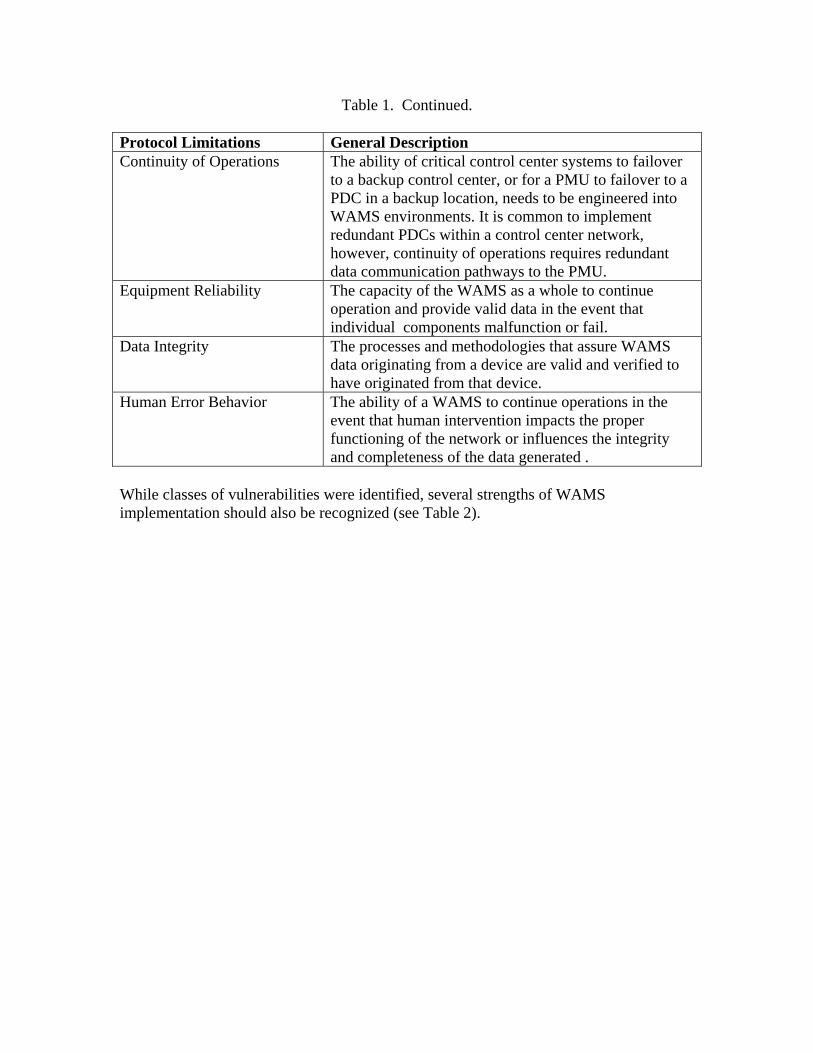
Table 1. Continued. Protocol Limitations General Description Continuity of Operations The ability of critical control center systems to failover
to a backup control center, or for a PMU to failover to a PDC in a backup location, needs to be engineered into WAMS environments. It is common to implement redundant PDCs within a control center network, however, continuity of operations requires redundant data communication pathways to the PMU.
Equipment Reliability The capacity of the WAMS as a whole to continue operation and provide valid data in the event that individual components malfunction or fail.
Data Integrity The processes and methodologies that assure WAMS data originating from a device are valid and verified to have originated from that device.
Human Error Behavior The ability of a WAMS to continue operations in the event that human intervention impacts the proper functioning of the network or influences the integrity and completeness of the data generated .
While classes of vulnerabilities were identified, several strengths of WAMS implementation should also be recognized (see Table 2).
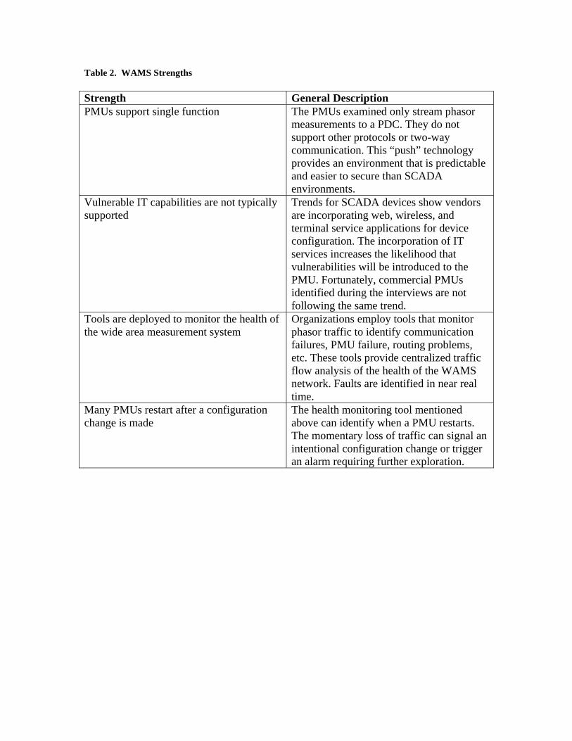
Table 2. WAMS Strengths Strength General Description PMUs support single function The PMUs examined only stream phasor
measurements to a PDC. They do not support other protocols or two-way communication. This “push” technology provides an environment that is predictable and easier to secure than SCADA environments.
Vulnerable IT capabilities are not typically supported
Trends for SCADA devices show vendors are incorporating web, wireless, and terminal service applications for device configuration. The incorporation of IT services increases the likelihood that vulnerabilities will be introduced to the PMU. Fortunately, commercial PMUs identified during the interviews are not following the same trend.
Tools are deployed to monitor the health of the wide area measurement system
Organizations employ tools that monitor phasor traffic to identify communication failures, PMU failure, routing problems, etc. These tools provide centralized traffic flow analysis of the health of the WAMS network. Faults are identified in near real time.
Many PMUs restart after a configuration change is made
The health monitoring tool mentioned above can identify when a PMU restarts. The momentary loss of traffic can signal an intentional configuration change or trigger an alarm requiring further exploration.
6
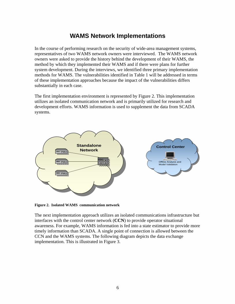
WAMS Network Implementations In the course of performing research on the security of wide-area management systems, representatives of two WAMS network owners were interviewed. The WAMS network owners were asked to provide the history behind the development of their WAMS, the method by which they implemented their WAMS and if there were plans for further system development. During the interviews, we identified three primary implementation methods for WAMS. The vulnerabilities identified in Table 1 will be addressed in terms of these implementation approaches because the impact of the vulnerabilities differs substantially in each case. The first implementation environment is represented by Figure 2. This implementation utilizes an isolated communication network and is primarily utilized for research and development efforts. WAMS information is used to supplement the data from SCADA systems.
PMUPMU
PDCPMUPMU
PMUPMU
Control CenterControl Center
Offline Analysis and Model Validation
Standalone Network
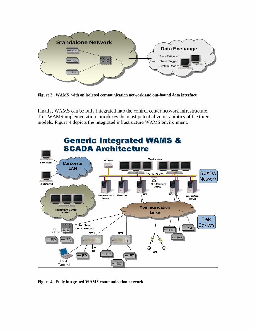
Figure 2. Isolated WAMS communication network The next implementation approach utilizes an isolated communications infrastructure but interfaces with the control center network (CCN) to provide operator situational awareness. For example, WAMS information is fed into a state estimator to provide more timely information than SCADA. A single point of connection is allowed between the CCN and the WAMS systems. The following diagram depicts the data exchange implementation. This is illustrated in Figure 3.
Standalone NetworkStandalone NetworkPMUPMU
PDCPMUPMU
PMUPMU
Data ExchangeData ExchangeState Estimator
Global Trigger
System Reader
Figure 3. WAMS with an isolated communication network and out-bound data interface Finally, WAMS can be fully integrated into the control center network infrastructure. This WAMS implementation introduces the most potential vulnerabilities of the three models. Figure 4 depicts the integrated infrastructure WAMS environment.
Figure 4. Fully integrated WAMS communication network

8
Reliance on External Time Source As indicated in Table 1, phasor measurement units utilize GPS to provide a time stamp for each phasor measurement (Figure 5). This dependence is indicated by the timing reference links in the above diagram. Global positioning systems are subject to three primary sources of interference: blocking, jamming, and spoofing. Two of these are directly attributable to the weak signal strength utilized by civilian GPS.
Phasor Data Concentrator
(PDC)
Data Handler
#1
Data Handler
#N
Settings & Code
Settings & Code
CommunicationInterface #NB
CommunicationInterface #NA
settingssettings
Communication System NPMU N
settings
Timing reference
Communication System 1
CommunicationInterface #1B
CommunicationInterface #1A
settingssettings
PMU 1
settings
Timing reference
Communication Link #1
Communication Link #N
•••
3φ voltage
3φ current
3φ voltage
3φ current
3φ voltage
3φ current
3φ voltage
3φ current
Figure 5. Technology elements for networking PMUs to a PDC using GPS The first form of interference, blocking, involves preventing the GPS satellite signal from reaching the antenna. The impact of a lack of GPS signal on a PMU is an area for further study. Good physical security practices, including placement of the antenna and utilizing physical security sensors, are the best mitigation techniques for this threat. Jamming is the act of preventing a receiver from tracking GPS signals. The third GPS interference is spoofing. To mitigate jamming and spoofing attacks, the timing reference must also be provided through an alternate source. For example, the SCADA equipment in the substation or the management port on the PMU can be used to supplement GPS time stamps.
9
Configuration Management According to NERC CIP-002, Standards CIP-002 through CIP-009 provide a cyber security framework for the identification and protection of critical cyber assets to support reliable operation of the bulk electric system. The authors of this paper contend that a wide area measurement system is a critical cyber asset that must comply with the requirements in the CIP series. The value of phasor measurements directly supports the reliable operation of the bulk electric system. Configuration management is defined as the management of security features coupled with a process to control changes made by equipment. Changes in this context include, but are not limited to, configuration settings, firmware, or hardware. The CIP series requires each organization to document and implement a program for managing access to protected critical cyber asset information. Another CIP control requires that “the Responsible Entity shall establish, implement, and document technical and procedural controls that enforce access authentication of, and accountability for, all user activity, and that minimize the risk of unauthorized system access.” During the interview sessions, PMUs were identified that do not support user authentication to the management port. The absence of a password makes complying with these requirements difficult, if not impossible. A PMU with no mechanism to authenticate the user means that anyone with access to the PMU can make any desired change. An organization may choose to document and implement compensating controls for PMUs without unique user authentication capabilities. Compensating controls include monitoring physical access to the substation, utilizing motion-activated cameras within the substation, or adding authentication solutions to the management port of the PMU.
10
Cyber Defense and Response Similar to SCADA devices, PMUs and PDCs were designed with the operational objective of availability in mind. Also analogous to SCADA systems and devices, cyber security was not a typical consideration. Consequently, many questions arise:
• How will a PMU behave if the management port is attacked?
• What will happen to the PDC if time stamps from multiple PMUs are impacting with a GPS spoofing attack?
• How resilient is a PDC to cyber attack?
• Is failure of WAMS equipment predictable?
• In what state do PMUs fail?
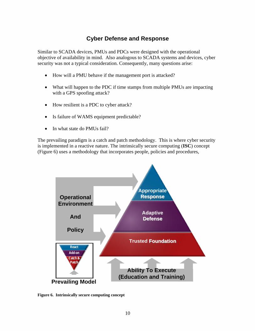
The prevailing paradigm is a catch and patch methodology. This is where cyber security is implemented in a reactive nature. The intrinsically secure computing (ISC) concept (Figure 6) uses a methodology that incorporates people, policies and procedures,
Figure 6. Intrinsically secure computing concept
Operational Environment
And
Policy
Ability To Execute (Education and Training)
AppropriateRReessppoonnssee
AdaptiveDDeeffeennssee
Trusted FFoouunnddaattiioonn
Prevailing Model
Catch & Patch
Add-on React
measurements, explicit trust into a trusted foundation. From that trusted foundation an adaptive defense and appropriate response mechanisms can be employed that are appropriate to the application and environment. ISC also incorporates a security process. Security is an ongoing concern and not a single review or audit. During the interview sessions, many warning signs were raised that indicate further research is needed regarding defense and response capabilities with commercial PMU and PDC devices. A recent test performed at PNNL with disruptive technology on SCADA equipment identified hundreds of vulnerabilities with a single protocol implementation. It is assumed by the authors that PMU and PDC devices will show similar vulnerabilities. Incorporating ISC concepts of secure code, changes to PMUs and PDCs are required to ensure they can identify a cyber attack and defend themselves.

12
Limited Situational Awareness One primary goal of a wide area measurement system is to improve the level of situational awareness regarding the reliability and robustness of the power grid. Situational awareness requires complete and accurate data for the decision maker or decision-making system. The risk of making an incorrect decision increases when only a partial view of the monitored environment is available. These information gaps may be the result of partial PMU deployment, equipment or communication outages, or deficiencies in information exchange with organizations. To mitigate these risks, planners must correctly identify the information gaps by asking questions such as:
• Where should PMUs be deployed? • Where are they currently deployed? • What PMU data do I need from others? • How do I obtain that data from others? • What decisions can I accurately make with the information at hand? • What decisions should not be made with partial views?
As phasor measurements are integrated into state estimators and other tools, it is imperative that ample and accurate measurements be provided. Full coverage of the control area will provide the most beneficial to situational awareness.
13
Implicit Trust The NERC Control System Security Working Group summarizes the problem of implicit trust exceptionally well on their website:
Control systems are the “brains” of the control and monitoring of the bulk electric system and other critical infrastructures, but they were designed for functionality and performance, not security. Most control systems assume an environment of complete and implicit trust.
While this quote is geared towards control systems, it applies equally well to wide area measurement systems. The common problems between control systems and wide area measurement systems include:
• Protocols do not support any mechanism to authenticate and validate communication.
• The communication media is subject to compromise • Remote locations may not be staffed, providing opportunity for compromise.
A common solution to address this problem utilizes a virtual private network (VPN) or a serial link encryption device to secure communication between the PMU and the PDC. In general terms, encryption is a technique to meet the security objective of confidentiality. If the encryption solution is not initiated natively by the PMU, there is opportunity for malicious traffic to be inserted and enacted by the PDC. Encryption by itself does not ensure a message is legitimate (Ferguson and Schneier 2003). The base of the triangle in the intrinsically secure computing diagram (Figure 6) above is a trusted foundation. Trust must come from many sources; the PMU must provide accurate information in a timely manner; the PDC must synchronize multiple phasor measurements correctly; and the communication between PMU and PDC is explicitly authenticated and validated. Once a trusted foundation has been established, decisions about defense and response can be made. Without trust, making cyber security decisions is problematic at best and completely incorrect at worst.

14
Protocol Use and Limitations Communication protocols serve as the basis for data transfer within the WAMS. The majority of the protocols used by a WAMS do not include security mechanisms in their specifications. It is left to the implementation of the protocol to employ security mechanisms. This section defines and addresses the security of the protocols that are currently in use within a WAMS environment. The protocols are divided into two types:
• WAMS streaming data protocols • WAMS data archiving protocols.
Figure 7 below represents a generic WAMS network with the WAMS protocols specified where they are likely to be used:
Figure 7. Locations of protocol use in a generic WAMS network As WAMS has developed, it has incorporated new technology into the system. Current WAMS infrastructure employs various transmission protocols such as serial, Modbus, OPC, IEEE 1334, PDCStream, and most recently IEEE C37.118 to transmit data.

Phasor Streaming Protocols Phasor streaming protocols are used to transmit phasor data in real time. These protocols can be implemented on a wide variety of communications mediums. These protocols, at a minimum, support a throughput of a minimum of 30 transmissions per second.
Institute of Electrical & Electronics Engineers (IEEE) Standard 1344 IEEE Standard 1344 is the first standardized protocol developed for synchronization and transmission of phasor measurements. This standard specifies data formats for the transmission of phasor measurements. It was also designed to synchronize data from multiple devices. To this end, the IEEE Standard 1344 contains specifications for time synchronization and data conversion formats. The specification does not address response time, measurement accuracy, hardware, software, or a process for calculating phasor measurements. Also, Standard 1344 has no specifications for security or transport. It leaves those considerations to the implementation of the protocol. A common synchronization source is required for a standard time reference point. The synchronization source must provide the number of seconds from the epoch of January 1, 1970 (otherwise known as seconds-of-the-century (SOC) in accordance with the network time protocol (NTP) and coordinated in agreement with the coordinated universal time (UTC). The protocol also provides a flag for synchronization loss. The time is recorded at the moment the sample is taken. IEEE Standard 1344 specifies three message or frame formats for the PMU: header, configuration, and data frames. There are two configuration files contained within the PMU. Configuration 1 contains all the possible phasors of the PMU and configuration 2 specifies the phasors that are actually to be sent, because only a subset of phasors can be sent in a data frame. The configuration frames should be stored by the receiving device to interpret the data coming from the PMU. Both the header and configuration frames generally follow the IEEE Standard C37.111-1991 (COMTRADE) format. The PMU must also be able to receive commands from connecting devices. The commands the PMU must be able to comply with are turn off the real-time data, turn on the real-time data, send a header frame, send configuration 1, send configuration 2, and receive a reference phasor in the data format. All the frames, including the command frames, end with 16-bit cyclical redundancy check (CRC) to catch transmission errors.
PDCStream PDCStream is a protocol developed by one of the WAMS network owners to aggregate PMU streams. IEEE Standard 1344 only covered the ability of streaming information
from one source. However, PDCs are needed to aggregate multiple streams of phasor data from PMUs. The PDCStream protocol is based on how the WAMS network owner specified the phasor data to be stored on the PDC. The PDCStream protocol is a modification of the IEEE Standard 1344 protocol and, as such, the implementation of the protocol determines how the data is transported and secured. The PDCStream protocol specifies two messages or frames; a descriptor frame and data frame. The descriptor frame is sent every minute on the minute. The descriptor frame is similar to the configuration frame specified within IEEE Standard 1344 in that it provides the information necessary for parsing the data frame. The data frame has two versions. The legacy version contains the PMU identities (IDs) and offsets that are contained within the descriptor frame. The new, compact version does not include the PMU IDs and offsets. There are also optional fields at the end of the format for including a special format of phasor data. A 16-bit exclusive Or (XOR) check field is calculated over the entire length of the frame and included at the end of the frame for catching transmission errors. A CRC can be substituted for the check word if more thorough error detection is required.
PDCxchng The PDCxchng protocol was developed by one of the WAMS network owners for transmission of compiled phasor measurements between PDCs over low bandwidth connections. The protocol uses a format that is incompatible with the IEEE standards. PDCxchng is obsolete. It should not be used in any future implementations of the WAMS architecture.
IEEE Standard C37.118 In 2006, the American National Standards Institute approved IEEE Standard C37.118, which is intended to replace IEEE Standard 1344. The IEEE Standard C37.118 addresses several shortcomings identified in IEEE Standard 1344. Unlike IEEE Standard 1344, IEEE Standard C37.118 accounts for phasor measurements from multiple PMUs. Additional fields have also been included in the Standard C37.118 to add needed functionality, as well as to conform to other standards. Standard C37.118 defines four types of message frames: data, configuration, header and command. These are the same four message types defined in Standard 1344. The first three message types are transmitted from the PMU/PDC and the last (command) is received by the PMU/PDC. Data messages are the measurements made by a PMU. Configuration is a machine-readable message describing the data the PMU/PDC sends and providing calibration factors. Header information is human-readable descriptive information sent from the PMU/PDC but provided by the user. Commands are machine-readable codes sent to the PMU/PDC for control or configuration.
Another change from IEEE Standard 1344 is modification of the sample field to be a fraction of second field. This is to be compatible with the standard International Electrotechnical Commission (IEC) 61850:2000. Compliance verification methods were also added for the synchro-phasor measurement requirements. The IEEE C37.118 protocol was designed to allow for the sending of multiple streams of phasor data at once, similar to the PDCStream protocol.
Security Considerations When assessing the security requirements of the WAMS, consideration should be given to the following critical aspects of streaming phasor data:
• Streaming phasor data is transmitted in real time. • Streaming phasor data conveys key information pertaining to the state of the grid
and is, therefore, business sensitive. The streaming phasor data protocols are implemented in the application layer of the Open Systems Interconnection Basic Reference Model (OSI) (layer 7). None of the current standards of streaming phasor data requires implementation of security in the protocol. Therefore, any implementation of security mechanisms into the streaming phasor data protocols requires that those mechanisms be built into the lower layers of the OSI model. Security mechanisms for streaming phasor data must take into consideration the real-time nature of the WAMS. The availability of data is crucial to the system. Without accurate data arriving in a timely manner, the WAMS can not function and the impact on other systems that use WAMS data will be detrimental. The high speed availability requirements of WAMS demand that the security enhancements added to deal with the confidentiality and integrity of the phasor data must not adversely impact the data’s availability. Data integrity is also a security consideration for the WAMS. The malicious insertion of unauthorized software commands into the system would be detrimental to the system. The IEEE standards for streaming phasor data allow for a few simple commands to be handled by the PMU. While these commands do not allow for reconfiguration of the device as do some SCADA open standards, such as DNP3, they do allow for remote disabling of phasor data transmissions. To prevent unauthorized commands, a signature of the data can be created and sent with the phasor data. This signature is commonly referred to a message authentication code (MAC). A MAC that uses a keyed cryptographic hash is known as a HMAC. An HMAC uses a cryptographic hash of the data created by seeding the hashing algorithm with a private shared key value. The data and the HMAC are sent to the recipient. The HMAC is recreated by the recipient using the data and the shared key value and if the two HMAC values match, the data is authentic.
WAMS data also conveys key information concerning the state of the electric grid. This information is business sensitive to the network owner and partner utilities. Therefore, if phasor data transverses publicly accessible communication medium, such as the internet, encryption should be used to prevent interception by a competitor. As a result of the real-time nature of streaming phasor data, the encryption methodology employed to enforce data confidentiality must be fast and light. Therefore, encryption of the streaming data should be performed by a symmetric algorithm, such as advanced encryption standard (AES), because they are faster than asymmetric algorithms. A major issue with authentication and encryption is how to handle key distribution. Some possible methods of key distribution are creating a public key infrastructure (PKI), Diffie-Hellman key exchange, or shared keys if the number of devices is small enough. The key distribution implementation should be chosen based on how the network architecture and the underlying protocols are used. Some available solutions for encrypting and authenticating the streaming phasor data protocol over an internet protocol based network are IP security (IPSEC) virtual private networks (VPNs) and datagram transport layer security (DTLS) protected data channels. Currently, VPN tunnels are being used across the internet to create connections between one network owner’s sites. Because of the necessity for user datagram protocol (UDP) transport for the streaming of data, the popular transport layer security (TLS) protocol can not be used. However, a hybrid of TLS and IPSEC was developed, called DTLS, which can be used to secure connectionless datagram traffic and may be useful in WAMS infrastructures. However, the optimal solution would be the creation of a private network for transporting WAMS data, similar to NERCNet used by the North American Electric Reliability Corporation, with the additions of optional security enhancements to the IEEE standards to support authentication and encryption. Archival and Analysis Protocols Archival and analysis protocols are used primarily for phasor data analysis and trending. These protocols do not support high telemetry rates and are, therefore, unsuitable for real-time data transmission. The use of these protocols is expected to be limited to the WAMS network owner’s internal data communication network. As such, security considerations for the use of these protocols differ from the real-time streaming data protocols.
IEEE Standard C37.111-1999 (COMTRADE) COMTRADE is a specification of a file format that represents transient waveform and event data. The format was created to be easily parsed and read and able to handle the multitude of generating, storing, and transmitting sources of data within the industrial power environment. COMTRADE was developed as a file format for storage on a physical medium and is not optimized for transmission over communication networks.
Because of these efficiency and speed problems, COMTRADE is used within the WAMS network to perform protracted operations. Examples are transferring data to and from archival sources. Each COMTRADE record consists of four files: 1) header , 2 configuration, 3) data, and 4) information. All four files must have the same name associated with the record and only differ in their extensions. The header file is an optional free form text file created by the generator of the data and can contain any information needed to define, scope, describe, (etc.) the data. The ASCII text configuration file, as with the phasor streaming protocols, defines the format of the data file. The data file contains the captured analog and digital values. The data file can be either ASCII text or binary, which is determined by a field in the configuration file. The information file contains auxiliary information that may allow for additional manipulation and analysis of the data file. It is an optional file to allow for backwards compatibility and is formatted in Windows TM .ini file format. The file format allows for public sections and private sections.
Object Linking and Embedding (OLE) for Process Control (OPC) OPC is an open standard set of protocols developed in 1996 by the OPC Foundation for the automation and process control industries to create a common format for exchanging data between the many differing vendors’ systems. Initially, OPC was developed around the Microsoft OLE, component object model (COM) and distributed component object model (DCOM) technologies and only distributed real-time data. However, OPC has been a continuously evolving suite of protocols that has since been adapted to allow for the following:
• alarm and event reporting • batch transmissions • server to server communication (on top of the original client-server architecture) • access to historical data repositories • simple object access protocol (SOAP) and web service interfaces instead of
distributed component object model (DCOM). Because there have been many concerns about DCOM’s security history, OPC Foundation has also developed a set of security specifications to help in building a secure OPC server. At the time this document was written, the OPC Foundation was in the last stages of releasing a full update to the OPC Standard, called OPC Unified Architecture (UA). One of the goals of the new OPC UA specification is to create a more portable set of protocols that are not tied to a single platform because the initial version was built around Microsoft technology. Another goal was to redesign all of the components into a unified whole, eliminating some of the inconsistencies the old protocols suffered from. The OPC UA is going to be backwards compatible, but will no longer use COM or DCOM. It will instead be based around some open standard web services specifications. At the time of this writing, the OPC UA is scheduled to be fully released in mid-late 2007.
Security Considerations The archival and analysis protocols are used primarily within the control center environment. As such, the data will must likely be used on the utilities’ enterprise local area network (LAN), and it is not necessary for the data to enter into a public enclave. COMTRADE was developed as a file format for storing digital copies of transient waveform and event data. It was not developed to support electronic transmission. Conversely, OPC has undergone optimization and a new version is due out soon that has incorporated security mechanisms. The original version of OPC was based upon DCOM, which in the past has documented vulnerabilities and know exploits, such as the Sasser and Blaster worms. However, as a side effect of the known issues, a lot of scrutiny has been applied to the DCOM protocol. Subsequently, the OPC Foundation has created a specification for securing DCOM. The newer versions of OPC are based around SOAP and web services that can utilize HTTP-based security mechanisms as well as newer security features being developed for SOAP. Examples of which are:
• SOAP security extensions • The XML Encryption Working Group, by the World Wide Web Consortium
(W3C).
The new OPC UA, which is to be completed within the year, is a re-architecting of the OPC protocol into a more unified structure with security mechanisms built in. Use of OPC within a WAMS should follow the security specifications laid out by the OPC Foundation.
21
Communication Infrastructure Wide area measurement systems in use today utilize several common communication infrastructures – serial, analog microwave, or VPN. Each of these communication methods contains vulnerabilities that can be used to interrupt communication or otherwise compromise the WAMS. As new communication technologies are migrated into the energy management system, implementation of WAMS security will also have to adapt to these new technologies and their associated vulnerabilities. Present Communication Infrastructure This section represents a short survey of communications technologies used by current network owners. The technologies covered range from serial communication to virtual private networking. The subsections give a general overview of the communication technology and the communication technology’s associated security considerations.
Serial Communication Serial communication is primarily used in SCADA networks and provided the original infrastructure for the WAMS. Some network owners still use serial communication in portions of their WAMS network. However, high speed modems are required to achieve the 30 samples/second data rate of the WAMS communication protocols.
General Data Data format: RS-232 Communication speed: 2400 bps to 115,200 bps
Serial Communication Security Considerations Any system that employs serial communication through modems is susceptible to various attacks on those modems. The technique of war dialing is used to identify open lines with modems on the system. Well know modem command sequences can give an attacker access to the WAMS and its business sensitive data.
Analog Microwave Analog microwave radio systems have been used to transmit and receive information between two points dating from 1950s. Analog transmission uses a continuous signal to carry information from point to point. Analog microwave is used by WAMS network owners to connect remote PMUs to a PDC when a wired connection is not feasible.
General Data Electro-magnetic (EM) Ultra-high frequency (UHF) (0.3-3 GHz) spectrum range: Super-high frequency (SHF) (3-30 GHz) Extremely-high frequency (30-300 GHz) EM spectrum regulation: Licensed. Licenses are available from the FCC (US), ACA
(Australia) or ETSI (Europe), etc. Network architecture: Point to point. Distance: Distances of up to 60 kilometers (~37 miles).
Components A modern microwave radio system consists of three basic components forming a radio terminal, with two terminals required to establish a microwave communications link, commonly referred to as a “hop”:
• Radio frequency (RF) units are used for up-converting the modulated carrier signal to microwave or millimeter-wave frequencies and amplifying the signal up to around 1 watt (referred to as 0 decibels or dB in RF terminology).
• An analog modem interfaces with terminal equipment, converting customer traffic
to a modulated radio signal and vice versa.
• Passive parabolic antennas are used to transmit and receive the signal.
Analog Microwave Security Considerations The following considerations are important microwave security considerations:
• It is easier to intercept than cabled media. A single radio anywhere in the broadcast range of both the sender and the receiver of a radio link can eavesdrop on radio communications, while two receivers, each stationed behind and in the line-of-sight of the target transponders, can record the data being sent between them. Alternatively, two receivers directly between the transponders can eavesdrop on the communications, and because the power requirement is squared at twice that distance, the eavesdropping dishes can be much smaller.
• Physical vulnerabilities of related equipment appear to be minimal because the
equipment is generally located on company property, in protected areas.
• In an analog microwave system, possible threats include link jamming and signal monitoring and recording.
• Vulnerabilities include an attacker learning the protocol and frequency, signals
sent in the clear and on a common channel, and content sent in the clear.
Virtual Private Networks Virtual private network is a term used to describe various technologies that secure communication between two parties across a non-secure public network. Those network owners who employ VPNs in their WAMS use the IP Security (IPSEC) suite of protocols to establish the VPN. The IPSEC suite of protocols provides methods for authentication and encryption of WAMS data at the internet protocol (IP) packet level. IPSEC also employs methods for cryptographic key establishment.
General Data Communication medium: Ethernet (IEEE 802.3) Protocol suite: IPSEC (IETF RFCs 4301–4309).
VPN Security Considerations IPSEC creates a virtual extension of the WAMS network by encrypting network traffic at layer 3 of the OSI model. This methodology encrypts the WAMS network data and the internal addressing scheme of the WAMS network itself. A WAMS user, therefore, has access to the entire WAMS network and can attempt to access unauthorized WAMS resources and data. Business sensitive data can be easily accessed, and false or misleading data can be uploaded to the system. There are also issues concerning data loss caused by connectionless orientation of some of the WAMS data transfer protocols. Communication Infrastructure Trends This section describes the various communication technology trends that have been observed migrating into control system implementation. There is every expectation that as the WAMS evolves, some or all of the technologies described will be incorporated into the WAMS communication infrastructure. A brief overview of the communication technology is given, along with the communication technology’s associated security considerations.
Fiber Optics Fiber optics (or fiber) is a term used to describe communication technologies that use glass or plastic fibers to propagate light as a communication medium. Because of the nature of light used as a transmission medium, fiber optic cables can be used for long distances without the need for signal enhancement. As such, fiber optics are typically used for communication distance of over 200 meters. The optical fibers also offer high bandwidth capacities with a single fiber, being able to achieve transfer rates of up to 40 Gigabit/second and fiber cable being able to transfer in the Terabit/second range.
Components
• Fiber cable are available in 9, 50, 62.5, 100 micron sizes. Larger sizes have higher capacity and subsequently higher cost.
• Fiber optic transmitters convert electrical signal to optical signal. There are two
types of optical transmitters, laser diodes and light emitting diodes (LEDs). Laser diodes are more expensive but also more powerful allowing for longer distance transmissions. LEDs are an older technology that is less powerful but cheaper.
• Fiber optic receiver uses photodiode or photocell to capture optical signal and
convert it back to electrical signal.
• Optical regenerator boosts weakened signal to extend the range of an optical signal.
Communication Methods
• Single-mode fiber is used primarily for long distances and can go 50 times the distance of multi-mode. It employs a powerful laser diode and can transmit infrared light in wavelengths between 1300 and 1550 nm. The system transmits in only one mode and is less susceptible to signal attenuation and distortion from overlapping light pulses. Single mode has a higher cost than multi-mode.
• Multi-mode fiber is used primarily for close internal communication wiring. It
employs LEDs and transmits light between the wavelengths of 850 and 1300 nm. It transmits in multiple modes, or angles of the light entering the fiber, which squeezes more bandwidth out of the less powerful LEDs but also restricts the distance at which it can be used. Multi-mode fiber is more economical for shorter distances and less bandwidth-intensive applications.
Acquisition Practices
• A third party (i.e., a telecommunications company) leases a connection between two fiber networks. The third party controls the transceivers to light the fiber at both ends and can provide SONET, asynchronous transfer mode (ATM), and ethernet interfaces. A lambda can be leased, providing a single wavelength or channel for use, or an indefeasible right of use can be established, which allows a capacity to be completely rented for a certain length of time (generally around 10 years).
• Dark fiber is the practice of buying some unused portion of a fiber installation
from a carrier. Purchasing dark fiber generally requires that the purchaser procure their own transceivers for communication. Maintenance and operation of the dark fiber can be outsourced. Generally operations and maintenance of the fiber is outsourced to the company it was purchased from.
• Installing fiber optic cable can take months to plan and get all the necessary
permits. Installation also requires more expertise than copper and Ethernet cabling.
Architecture
• Fiber optic is connected from one point directly to the other. The traffic is serially connected. Point-to-point connections do not inherently provide any means of redundancy, and would require more than one point-to-point connection or another secondary form of communication to protect against communication failure. Advantages of this architecture include:
– Simple to architect and plan.
– Not necessary to use routing technologies.
A disadvantage of this architecture is that it requires fiber connections between each station.
• Fiber is redundantly connected in a token passing ring. Fiber distributed data
interface (FDDI) allows 2 km between nodes using multi-mode and 10 km for single mode. An FDDI has a primary fiber connection and a secondary, redundant connection to provide reliability. The two rings run in opposite directions and during normal operation, the primary ring transmits data while the secondary ring remains in a standby condition. When a connection fault is encountered, the two rings connect, creating a single ring, skipping the point of failure. There are four types of connections to an FDDI: single-attachment station (SAS), dual-attachment station (DAS), single-attached concentrator (SAC), and
double-attached concentrator (DAC). A DAS connects directly to both the primary and secondary rings and becomes a node in the FDDI. If a DAS is taken offline, it becomes a point of failure that would force the two rings to connect around it. An SAS on the other hand connects to the primary ring only through a concentrator. Concentrators are connected to one or both of the rings and provide a connection point for other devices. Concentrators allow devices connected to the FDDI to be powered without causing communication problems on the ring. Single rings can go 200 km while a dual ring FDDI can extend to 100 km. The rings provide up to 100 Mb/s and in normal operation, the secondary ring can be utilized to provide 200 Mb/s. FDDI has a limit of 500 stations. An advantage of this architecture is that FDDI provides a fast backbone of communication with redundant links.
There are no security mechanisms at the FDDI level. Security must be provided at higher layers of the OSI model, for instance IPSEC.
• Multi-protocol label switching (MPLS) can run on top of many OSI layer 2
protocols and under any layer 3 protocol. It offers the flexibility of routed switching with the speed of static circuit routing. A cloud of routing equipment is used as a backbone. The edge routers are responsible for configuring routes between each other, generally by the IP address coming into the cloud. The edge routers will use something similar to the border gateway protocol (BGP) to configure their routing tables. The internal routers will run a quicker internal routing protocol such as routing information protocol (RIP) or open shortest path first (OSPF). When a packet hits an edge router, a label is added to the packet that determines the next hop inside the MPLS cloud. Labels are discarded and added as the packet is forwarded, and internal routers do not know where the packet is coming from or going. The internal routes are essentially static. The label and forward method create VPN tunnels and more tunnels can be created inside the initial one by adding an additional set of labels. When the pack reaches the exiting edge router, all the labels should be removed so that the interfacing router can continue routing with whatever protocol came in the other side of the cloud. Advantages of this architecture include:
– Fast and reconfigurable – Replaces ATM and frame relay with faster speeds.
Security considerations include:
– Security is equivalent to ATM and frame relay. – As long as the MPLS routes are configured correctly, traffic is tunneled
through the MPLS cloud.
Leasing MPLS - When leasing MPLS service from a service provider, the MPLS cloud is controlled by the service provider and they handle all of the routing,
configuring, and maintaining of the routers. There are basically two types of service that can be leased from an MPLS service provider: layer 3 VPN and layer 2 VPN.
MPLS Implementation - When implementing an MPLS fiber backbone, the WAMS network owner will be responsible for all of the configuration and maintenance of the routers. MPLS is complex and would require a great deal of resources initially to configure. However, if the network is set up correctly, the configuration should remain static with low maintenance if routes are not changed frequently. An advantage of this architecture is that everything is controlled by the WAMS network owner. Disadvantages include a requirement for a high level of upfront resources to install and configure.
Fiber Optic Unique Considerations The primary considerations relating to the implementation of fiber optic technology can be classified according to its advantages and disadvantages. Advantages are:
• Most future-proof technology, i.s., theoretical bandwidths have yet to be reached.
• Scalability, i.e.,the transceivers just need upgrading to receive the benefits of technological advancements.
• Most cost effective for long distance, high bandwidth applications.
• Prices are still falling
• Distance, i.e., generally needs a repeater every 80 km
• Bandwidth, i.e.,1 to 10 Gb with theoretically higher bandwidths
• Interference, i.e., fiber is non-metal based and therefore is not susceptible to
interference by electromagnetic, radio frequency, and lightning. Fiber does not use electricity and thus does not create electromagnetic interference and is not affected by shorting and grounding.
• Size, i.e.,smaller and lighter than copper
• Environment, i.e.,practically impervious to atmospheric conditions.
Disadvantages are:
• Fiber optic communication is expensive. The transmitter and receivers are expensive and installation is complicated.
• Specialist skills are needed for installation and maintenance.

• Does not carry electrical current if that is needed to power end connection.
• Challenges integrating with other technologies. Media converters are necessary
to interface with legacy equipment.
Fiber Optic Security Considerations Installing surreptitious taps on fiber optic communications is simpler to facilitate than is generally believed. Using commercial equipment, an unobtrusive tap can be readily accomplished. The cable still needs to be protected. Splicing is the easiest form of tapping but is detectable by most network security systems. Splicing will create a short disruption of data and is noticeable. Bending the fiber to create micro-bends can make light leak from the fiber without disrupting communication. This method works better on slower data rates. Another tapping method includes transmitting light into the fiber and analyzing the interaction of the two light sources to determine the data.
Licensed Digital Microwave Licensed digital microwave changes the continuous signal used by analog microwave to a digital signal. This allows for greater data transmission rates with better data integrity. Using licensed digital microwave does require obtaining the appropriate transmission license from a regulatory agency.
General Data EM spectrum range: 2 to ~40 GHz EM spectrum regulation: Licensed. Licenses are available from the FCC (US), ACA (Australia) or ETSI (Europe), etc. Network layer(s): Physical and data-link layers of the OSI network model. Network architecture: Point to point accepts data (ATM, ethernet, etc) at one port and sends it out the other as microwave radio. Network speed: Up to 155 Mb/s Distance: Distances of up to 60 kilometers (~37 miles). Security: Trunk encryption
Components A modern digital microwave radio system consists of the same components as an analog system with the addition of a digital modem.
• A digital modem interfaces with digital terminal equipment, converting customer traffic to a modulated radio signal and vice versa.
• Radio frequency (RF) units are for up-converting the modulated carrier signal to
microwave or millimeter-wave frequencies and amplifying the signal up to around 1 watt (referred to as 0 decibels, or dB in RF terminology).
• Passive parabolic antenna are used to transmit and receive the signal.
Digital Microwave Radio Unique Considerations Advantages of this architecture include:
• Rapid deployment, i.e., a microwave link can be installed in as little as 1 day.
• No right-of-way issues, i.e.,radio spans all obstacles such as roads, railways, etc., avoiding any requirement to seek permissions that inevitably are costly and introduce time delays.
• Flexibility, i.e.,the capacity of a microwave link can be easily increased at
minimal or even no cost. Radios can also be redeployed if network needs change or as a result of customer churn. Losing customers does not mean assets are lost like in the case of fiber build.
• Easily crosses city terrain, i.e., in many metropolitan and city authorities,
excavation to install fiber under a public roadway is either extremely restricted, prohibitively expensive or is even banned outright.
• Operator-owned infrastructure, i.e.,no reliance on competitors.
• Low start-up capital costs, which are independent of the link distance.
• Minimal recurring operational costs.
• Radio infrastructure already exists for many networks in the form of rooftops,
cellular masts and existing radio transmission towers.
• Microwave radio is not susceptible to common catastrophic failure of cable systems caused by cable cuts, and can be repaired in minutes instead of hours or days.
• Better resilience to natural disasters (flood, earthquakes).
• Immunity to noise
• Ability to operate in adverse environmental conditions.
Disadvantages of this architecture include:
• Sensitivity to precipitation resulting in signal fading
• Multi-path interference resulting in signal fading.
Digital Microwave Radio Security Considerations Digital microwave radio point-to-point communications may be encrypted using a variety of technologies. Current vendor offerings include the use of the OpenSSL protocol suite to National Security Agency (NSA) Type 1. Encryption does impact the data transfer rate associated with the link. Military grade units have data rates of 9.6 Kb/s to 13 Mb/s. Civilian products advertise data rates as 4, 8, 12, 16, 28 DS1+1 DS1, 1 DS3+1 DS1, 3 DS3+3 DS1, OC-3+1 DS1, NxDS1+2x10/100BASE-T (4 to 100 DS1 equivalent capacity, ~6 to 155 Mb/s).
Private Broadband (WiMax, IEEE 802.16) WiMAX is defined as Worldwide Interoperability for Microwave Access by the WiMAX Forum, formed in June 2001 to promote conformance and interoperability of the IEEE Standard 802.16. WiMAX is used as a last mile wireless broadband access and it is an alternative to wired connectivity such as fiber. WiMAX provides fixed, nomadic, portable and, soon, mobile wireless broadband connectivity without the need for direct line-of-sight with a base station. Private broadband is similar to WiMax, but uses licensed frequencies, usually in the 700 MHz band. An access point feeds customer-premises equipment (CPE) located inside the substation and offers ethernet directly. The access points are backhauled to a network operating center, which is usually not at the utility’s main SCADA control center, so a leased line (T1, T3 or OC-3) is used to make the final connection. This system is most often run by another company, and capacity is leased out. It is ethernet at both ends to ensure a simple connection and any kind of VPN internet protocol traffic is able to be transported over the link.
Communication Methods Private broadband is WiMax but uses licensed, lower frequencies in the 700 MHz range that travels further distances and is able to better penetrate obstructions. Some service providers made claims of 27 Mb/s downstream and 8 Mb/s upstream in each sector (off of one base station). Most service providers are using WiMax technologies in the 802.16 family, but some have mentioned using cellular technologies like code division multiple access (CDMA).
Components This is a leased technology and requires customer-premise equipment, such as radios and antennas. The service delivers ethernet interface. It is being marketed as a solution to enable management of remote utility locations, including accurate, real-time assessment of consumption, the reduction of excess power generation, and the reallocation of power generation.
WiMax Unique Considerations Advantages of this architecture include:
• Has fairly good distance capabilities and penetration compared to other wireless solutions.
• Access to broadband in more rural areas, where other technologies have not
penetrated.
• Some service providers offer bandwidth prioritization for critical applications.
• Operates on licensed 700 MHz frequencies so there is less impact from interference.
Disadvantages of this architecture include:
• This is a fairly new technology. Therefore, availability of the service will be an issue for some time.
• The 700 MHz band is due to be released by TV stations by the end of 2006, but a
recent white paper submitted to the FCC by Motorola stated that ~70% of the country’s population lives in areas that are totally or partially blocked by incumbent TV stations.
• Significant work is still being done on the WiMax specifications and there has not
been a lot of adoption to see how well it will perform in a lot of situations.
• Challenges integrating with other technologies.
• Because this service is managed by a service provider and delivers ethernet
connectivity, it should be fairly simple to integrate with other technologies.
WiMax Security Considerations This is a managed service, so there is a loss of owner control over part of the network. The WiMax specification supports the use of either the triple Data Encryption Standard (3DES) or advanced encryption standard (AES). It also specifies that base station equipment come equipped with a dedicated processor for encryption. All traffic must be encrypted using counter mode with cipher block chaining message authentication code protocol (CCMP). The end-to-end authentication uses the extensible authentication protocol (EAP) and pair-wise master key (PMK) methodology. This methodology relies on the transport layer security (TLS) standard of public key encryption.
Multiple Address System Radio Multiple address system (MAS) radio is the traditional 900 MHz master/slave radio that can connect PMUs to a PDC in the WAMS. It offers serial connections, but ethernet radios are available. Typical speeds are 64K to 512K. A new 1.4 GHz band will increase these speeds, but it still offers only connectivity and less secure encryption, so some users are looking for a replacement. Because of the low cost and ease of use, these types of radios will continue to embed themselves in the market place for years to come.
Communication Methods Multiple address system radio is a radio service, generally using the 900 MHz frequency, which covers a 40-km radius from the antenna. It is used for sensor-based and transaction systems (ATMs, reservations, alarms, traffic control, etc.). MAS is a point-to-multipoint architecture, either one or two way, which connects a master station to at least four end stations. MAS is generally used for remote terminal unit (RTU) and intelligent electronic device (IED) communication. Use of MAS radio networks outside the substation fence is often thought to be impractical because of the cost associated with installing a RTU to interface between the radio and the IED. There are two methods of using MAS systems: licensed frequencies or unlicensed spread-spectrum frequencies. Advantages of licensed frequencies include:
• Can use higher powered radios extending useable distances
• FCC granted exclusive use to frequencies in an area with a 70-mile radius, cutting down interference.

Disadvantages of this architecture include:
• Application for frequency license from the FCC can take months to acquire.
• Licensed frequencies are becoming saturated and can be hard to acquire around larger cities.
Spread-spectrum (License Free)
Its principal advantage is that it is license-free. Disadvantages include1) must comply with FCC restrictions for unlicensed radio use and use low powered spread spectrum radios, and 2) unlicensed radio frequencies have interference.
Components System components include:
• Licensed frequency radios or spread spectrum 1-watt radios
• Omni-directional antennas at the master sites
• Direction Yagi-Uda antennas at the end sites
• Repeaters (if necessary).
• A necessary license from the FCC to use certain frequencies and higher powered radios (exclusive use for a frequency is granted within a 70-mile radius to reduce interference).
MAS Radio Unique Considerations Advantages of this architecture include:
• 40-km radius wireless communication and with repeaters, can be longer.
• Low installation cost.
• Operates on licensed 700-MHz frequencies so less impact from interference.
• Good for rough terrain where cabling is hard to install.
Disadvantages of this architecture include:
• Low bandwidth supporting up to 19.2 Kb/s (unlicensed frequencies can achieve higher bandwidths at higher frequencies (generally 2.4 GHz) but interference and distance are impacted)
• Both licensed and unlicensed frequencies are becoming oversaturated
• Challenges integrating with other technologies
• MAS radio technology is used in low bandwidth and short distance applications
because of distance and interference constraints. MAS radio technology generally supports serial communication, so it may require protocol conversion to integrate with other technologies.
MAS Radio Security Considerations Security considerations include:
• Digital radios often use manufacturer-specific proprietary encryption
• Unlicensed radio use requires spread spectrum, frequency hopping
• No inherent encryption or authentication in the communication medium.
35
Continuity of Operations Continuity of operations (COO) addresses the capability to continue to operate the WAMS in the event of disruption to normal operations. Ensuring COO for a WAMS entails the preparation, testing, and maintenance of specific policies and procedures to enable network owner actions to recover the WAMS operational status after the occurrence of system disruption. The ability of critical control center systems to fail-over to a backup control center, or for a PMU to fail-over to a PDC in a backup location, needs to be engineered into WAMS environments. It is common to implement redundant PDCs within a control center network; however, continuity of operations requires redundant data communication pathways to the PMU. Disruptions can come from natural disasters such as earthquakes, tornados, floods, or from manmade events such as riots, terrorism, or vandalism. The ability for the WAMS to function after such an event is directly dependent on implementing policies, procedures and resources in place ahead of time to protect from an extended outage of the WAMS. The key areas for planning operational continuity for WAMS are maintenance and disaster recovery capabilities.
Maintenance Regularly planned and scheduled maintenance is mandatory to sustain the operational status of a WAMS. A well planned maintenance program regularly tests the WAMS for single points of failure and documents the following:
• Master data sheets for the various components of the WAMS that contain calibration and configuration settings
• Surveillance records for testing individual components and system response to
planned transient events
• Qualification records of the individuals performing calibration, configuration and surveillance tests.
Regularly scheduled calibrations of the WAMS components ensure data reliability and integrity. Regular testing of the WAMS communications links ensures that the system is functioning optimally. Documenting the qualifications of individuals performing calibrations, configuration and surveillance tasks add accountability to the WAMS maintenance program.
Disaster Recovery Continuity of operations requires that a WAMS be able to withstand anticipated operational transients and, in the case of an extraordinary event, be able develop, implement and review adequate disaster recovery plans. Electrical energy generation and transmission are classified as critical infrastructure. As such, a WAMS design must be made invulnerable to a single point of failure in its operating environment. The redundancy implied with this design imperative will dictate that the system will contain all the necessary components for fail-over to a redundant communication system. This would ensure continual operation in the event of losing operational functionality of the primary communication system. As the technologies used in the WAMS start to transition into the control function role, the redundancy requirement for disaster recovery will become paramount. Therefore, every single point of failure, such as communication medium, data storage, operation equipment and facilities, etc. needs to have a redundant failover capability. Policies, procedures and training also need to be established to ensure that staff are proficient in their responsibilities in the event of an emergency to ensure that recovery of operational status is completed expeditiously. Training should be completed upon initial qualification of individuals responsible for the operation and maintenance of the WAMS as well as refresher training for those individuals occurring at least annually. The organization operating the WAMS should also develop training scenarios that incorporate anticipated operational occurrences as well as disaster recovery scenarios. Currently there are different implementations of disaster recovery plans for wide area management system network owners. For example, one network owner has implemented a disaster recovery fail-over plan for their WAMS. The disaster recovery plan implements the open shortest path first (OSPF) algorithm to handle the data routing configuration during the fail-over. In the near future, this network owner will be implementing advanced networking devices that will have direct redundant failover capabilities. Two separate internet service providers (ISPs) are used for external connectivity, and phasor data is piped to two concurrently staffed control locations. However, another WAMS network owner has plans to implement disaster recovery with manual fail-over between control centers.
37
Equipment Reliability The value of a WAMS network is essentially only as good as the quality and integrity of the data it generates and transmits. It is, therefore, dependent on the reliability of both hardware and software components deployed throughout its infrastructure. In this context, reliability embraces other constituent qualities including basic accuracy (precision), dependability, repeatability and availability. All of these attributes contribute to the operator and analyst, respectively, being able to rely on WAMS infrastructure transmitting accurate, real-time information on grid status and behavior into the control room, in addition to creating reliable and consistent records that will support retrospective analysis in the future. When data are transmitted over a WAMS network, the reliability of all its nodes and links can affect data quality and completeness. While a WAMS typically has multiple redundant information sources and pathways that can compensate somewhat for the partial data loss or corruption, a primary need is for the instruments residing at the WAMS/grid interface to provide consistent information under all conditions. In the projected evolution of WAMS infrastructure, PMUs or digital instrumentation equivalent to them are envisioned as the technology of choice for mission-critical applications such as real-time security assessment and stability control. Therefore, because PMUs are expected to generate at least 50% of the information transmitted by a WAMS, it is essential that they measure phasor quantities accurately and respond to grid conditions uniformly. As discussed below, achieving this goal appears to be still in the future. The products of several PMU vendors are installed in existing WAMS networks. Some instrument designs are more mature than others. None appears to be qualified to common performance specifications. Evidence for this is illustrated in Figure 8, which shows two disturbance records generated by PMUs on the same transmission line that are remarkably different in character. The 5L52 Custer Line voltage magnitude records are for a period of about 150 seconds before and after a Western Electricity Coordinating Council (WECC) system disturbance occurring on December 12, 2003. The record provided by instrument ING1 shows intense oscillatory behavior both before and after the event, which was not apparently detected by ING2. Each instrument also responded to the disturbance transient differently. Post-event analysis corroborated by other connected PMUs demonstrated the ING1 record was the one that was spurious. The oscillations this PMU “read” and transmitted as information through the WAMS network did not exist in reality but were apparently self-generated by a programmed artifact in the instrument’s internal microprocessor. When this type of PMU behavior occurs in a WAMS that functions only as a complement to conventional SCADA, it causes no direct harm to the grid. It is typically first identified during post-event analysis. In fact, the above example is one of a number of valuable lessons gained from retrospective evaluation of actual WAMS component behavior in the field. The variety and number of instruments deployed today contribute
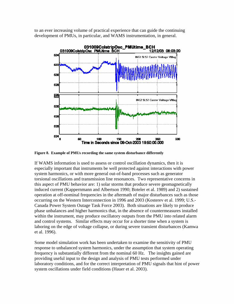
to an ever increasing volume of practical experience that can guide the continuing development of PMUs, in particular, and WAMS instrumentation, in general.
Figure 8. Example of PMUs recording the same system disturbance differently If WAMS information is used to assess or control oscillation dynamics, then it is especially important that instruments be well protected against interactions with power system harmonics, or with more general out-of-band processes such as generator torsional oscillations and transmission line resonances. Two representative concerns in this aspect of PMU behavior are: 1) solar storms that produce severe geomagnetically induced current (Kappernmann and Albertson 1990; Boteler et al. 1989) and 2) sustained operation at off-nominal frequencies in the aftermath of major disturbances such as those occurring on the Western Interconnection in 1996 and 2003 (Kosterev et al. 1999; U.S.-Canada Power System Outage Task Force 2003). Both situations are likely to produce phase unbalances and higher harmonics that, in the absence of countermeasures installed within the instrument, may produce oscillatory outputs from the PMU into related alarm and control systems. Similar effects may occur for a shorter time when a system is laboring on the edge of voltage collapse, or during severe transient disturbances (Kamwa et al. 1996). Some model simulation work has been undertaken to examine the sensitivity of PMU response to unbalanced system harmonics, under the assumption that system operating frequency is substantially different from the nominal 60 Hz. The insights gained are providing useful input to the design and analysis of PMU tests performed under laboratory conditions, and for the correct interpretation of PMU signals that hint of power system oscillations under field conditions (Hauer et al. 2003).
The dominant problem at the current stage of PMU development appears to be that of filtering. Some filtering defects can be compensated with an inverse filter, but out-of-band activity that has been aliased into the passband cannot be removed under general conditions. Study cases examined to date have relied upon a linear averaging process for primary filtering. Although rudimentary, this approach, known as a "boxcar" filter, is a familiar one, and it works well for purposes of illustrating the problem. However, uniform averaging with a "boxcar" filter is not sufficient for rejecting harmonics under high stress grid operating conditions. Thus, it is not a ready or adequate solution to assure the dependability of high performance PMUs.
The various implications of component unreliability discussed above, with primary focus on PMUs, may apply in some measure to other hardware and software components of WAMS infrastructure albeit with probably differing degrees of significance and system impact. The experience with currently deployed systems will add perspective to these issues as on-line deployment time accumulates. Basically, every component of a WAMS network must perform predictably and consistently under all conditions to which they are exposed. Any component aging, failure or aberrant behavior should be exposed by suitable means that both identify by tagging or filter out any compromised data that result. Unless all components deployed in a WAMS network can be demonstrated to perform consistently all the time and deliver trustworthy information, there will be an increasing probability that erroneous data may be transmitted to the control room. Here, the opportunities could increase in number and frequency for such information to bias or, at least, confuse the operator’s situation awareness (SA). If or when WAMS infrastructure becomes the primary source of real-time control information, such faulty data could misinform control decisions to the extent that consequential harm might be done to the system, especially when the grid is highly stressed.
40
Data Integrity Beyond the considerations related to cyber security treated elsewhere in this document, occasional data loss and/or corruption are expected to persist and need to be accommodated in WAMS design well into the foreseeable future of its evolution. The system cannot be cost-effectively engineered to preserve or assure the quality of all generated data. Random disturbances and transients, as well as aging and unpredictable failure of both hardware and software components, can be expected to temporarily interrupt or compromise individual data streams or instruments. In addition, as discussed in the next subsection, human behavior can result in lost or misdirected data. Therefore, redundancy should be built into WAMS infrastructure to compensate for some tolerable rate of data loss and corruption. This capability exists essentially in currently deployed WAMS networks that offer the general ability to work-around deficiencies in data used for retrospective analysis of power system behavior. Often, the loss of critical data describing, for example, a system disturbance, may still be compensated by interpolation, extrapolation and substitution of other information acquired from a number of WAMS connections to the grid. These data manipulations are often not straightforward or elegant but, nevertheless, provide important means for reconstructing events and understanding how the grid behaved. As the WAMS concept evolves into a source of real-time control information, there will be no time for work-around solutions if critical data are lost. This is seen as a major threat to the maintenance of SA in the control room, particularly when the grid is operating under stress. This type of scenario suggests that further measures be incorporated into WAMS infrastructure that guarantee the continuing availability of sufficient data to support decision making by operators under all conditions. An across-the-board solution of backing up essentially every instrument and data link would likely be an “overkill” response technically and uneconomic financially. In this regard, the overall integrity of data needed to support SA under normal operating conditions is generally less than that needed during an emergency. Future WAMS infrastructure could benefit from the careful design of a “smart” data assurance subsystem that dynamically tracks grid conditions. This methodology would assess the real-time adequacy of data connectivity, stream rate and other aspects of quality with respect to rates of change in measured phasor values, system frequency and other indicators of power system health. Strategically placed standby instruments and data linkage would be switched in as required to maintain predetermined levels of critical information flow depending on the urgency of the situation. Such a concept would show a minimal response when steady state conditions prevail but would provide information assurance when the grid exhibits the onset of dynamic behavior beyond certain threshold trigger levels.
41
Human Error Behavior The evolutionary pathway foreseen for WAMS infrastructure is from its present back-up role as reinforcement for heritage SCADA, through becoming the principal real-time information system in an integrated EMS. Some have a vision of the grid eventually operating under completely automated control, employing self monitoring and healing capabilities that will make human operators redundant. At the present rate of progress, such a vision will probably not be realized for several decades. Even if total grid automation ever comes about, human involvement is still likely to be essential in the analysis and interpretation of WAMS data describing past system behavior, especially major disturbances, as the basis for system planning and development. Thus, the performance of “humans-in-the-loop” will be an artifact of grid design and control, and specifically WAMS security, for the foreseeable future. The pathway to better management of human error in the grid control room is seen as primarily a two-pronged approach of: 1) providing and updating comprehensive training and 2) assuring that the information that operators use as decision bases provides unambiguous situation awareness without information overload. Training can often compensate for the face value of defective or incomplete control information, but the need for SA escalates rapidly as the lead time for operator action diminishes. Thus, operators with imperfect SA can generally function effectively during normal grid operations and to a great extent when rapidly developing abnormal conditions represent situations for which they have been trained. However, the importance of SA becomes paramount as a sound decision basis when grid status changes rapidly and in ways that are not instantly recognized or are totally beyond the operator’s trained experience. Human errors can also interfere with the generation, transmission and general adequacy of WAMS data outside the control room. The history of WAMS evolution is replete with instances when human error, oversight or negligence have caused critical data to be lost, corrupted or simply not generated in the first place. A full range of quite ordinary human behavior has been involved in these incidents including failure to energize equipment, lack of required diligence in maintaining records and not discriminating critically valuable data information from those suitable for destruction. In addition, aspects of human factors implicit in corporate policy controlling the management and legalities of information ownership have interfered with dissemination of WAMS data. So far, these issues have only frustrated a small part of the extensive post-event analysis effort conducted to date. As WAMS infrastructure evolves, such human factors could gain a higher level of significance and, therefore, should be addressed appropriately.
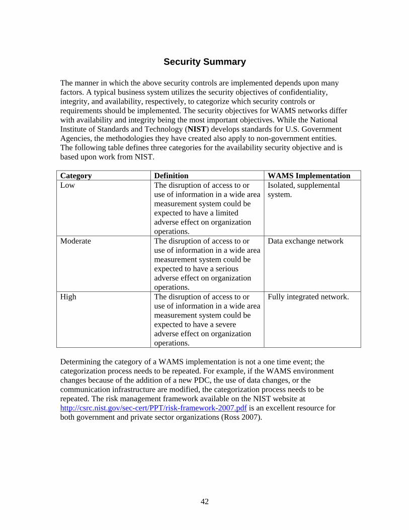
42
Security Summary The manner in which the above security controls are implemented depends upon many factors. A typical business system utilizes the security objectives of confidentiality, integrity, and availability, respectively, to categorize which security controls or requirements should be implemented. The security objectives for WAMS networks differ with availability and integrity being the most important objectives. While the National Institute of Standards and Technology (NIST) develops standards for U.S. Government Agencies, the methodologies they have created also apply to non-government entities. The following table defines three categories for the availability security objective and is based upon work from NIST. Category Definition WAMS Implementation Low The disruption of access to or
use of information in a wide area measurement system could be expected to have a limited adverse effect on organization operations.
Isolated, supplemental system.
Moderate The disruption of access to or use of information in a wide area measurement system could be expected to have a serious adverse effect on organization operations.
Data exchange network
High The disruption of access to or use of information in a wide area measurement system could be expected to have a severe adverse effect on organization operations.
Fully integrated network.
Determining the category of a WAMS implementation is not a one time event; the categorization process needs to be repeated. For example, if the WAMS environment changes because of the addition of a new PDC, the use of data changes, or the communication infrastructure are modified, the categorization process needs to be repeated. The risk management framework available on the NIST website at http://csrc.nist.gov/sec-cert/PPT/risk-framework-2007.pdf is an excellent resource for both government and private sector organizations (Ross 2007).
43
Conclusions There is no single cyber security solution that is appropriate for all WAMS implementations. For example, the security objectives differ for standalone and fully integrated WAMS networks. Securing WAMS infrastructures, per the NIST model, is a process that needs to be repeated when the environment or regulatory requirements change. In addition, cyber security should not be viewed as an end in itself but rather as one means to ensure the organization’s goal for a reliable WAMS network is achieved. The data provided to a control center by a WAMS network is similar to SCADA data; message availability and integrity are the primary security objectives. As WAMS data is incorporated into more and more applications, efforts to ensure the message itself can be explicitly trusted become increasingly important. Further research is also needed to address vulnerabilities associated with the dependence upon GPS for the synchro-phasor time stamp, the robustness of PMU hardware and software, and the ability of a PDC to handle a concentrated cyber attack.
44
References Boteler, D.H., R.M. Shier, T. Watanabe, and R.E. Horita. 1989. “Effects of Geomagnetically Induced Currents in the BC Hydro 500 kV System.” IEEE Trans. Power Delivery, vol 4, no. 1, pp. 818-823, January. Ferguson, N. and B. Schneier. 2003. “Practical Cryptography.” ISBN 0-471-22357-3, John Wiley & Sons, Indianapolis, IN. Hauer, J. F. and J. G. DeSteese. 2007. Descriptive Model of a Generic WAMS. PNNL-16254 (limited distribution), Pacific Northwest National Laboratory, Richland, Washington. IEEE. 2006. “IEEE Standard for Synchrophasors for Power Systems.” IEEE Std C37.118tm-2005. March 2006. The Institute of Electrical and Electronics Engineers, New York. Kappernman, J.G., and V.D. Albertson. 1990. “Bracing for the Geomagnetic Storms.” IEEE Spectrum, vol. 27, no. 3, pp. 27-33, March. Kosterev, D.N., C.W. Taylor, and W.A. Mittelstadt. 1999. “Model Validation for the August 10, 1996 WSCC System Outage.” IEEE Trans. Power Syst., vol. 14, no. 3, pp. 967-979, August. North American Electric Reliability Corporation. 2002. “Critical Infrastructure Protection Series”, CIP-001-01 to CIP-009-01, NERC, June. Princeton, New Jersey Ross, R. 2007. “Managing Enterprise Risk in Today’s World of Sophisticated Threats A Framework for Developing Broad-Based, Cost-Effective Information Security Programs.” The National Institute of Standards and Technology (NIST), Washington, DC. U.S.-Canada Power System Outage Task Force. 2003. “Interim Report: Causes of the August 14th Blackout in the United States and Canada.” November. Washington, DC.
45
Web Links: BPA http://www.bpa.gov EPRI http://www.epri.com IEEE http://www.ieee.org NIST http://csrc.nist.gov North American Electric Reliability Corporation
http://www.nerc.com
OPC Foundation http://www.opcfoundation.org Transmission Reliability Program http://www.oe.energy.gov/randd/trans_reliability.htmWAPA http://www.wapa.gov WECC http://www.wecc.biz