secured hf image transmission system … · hf data communication system: hf transceiver, modem,...
TRANSCRIPT
SECURED HF IMAGE TRANSMISSION SYSTEM
(PENGHANTARAN IMEJ SECARA SELAMAT MENGGUNAKAN
FREKUENSI TINGGI)
AHMAD ZURI B SHA’AMERI
RESEARCH VOTE NO:
74114
Jabatan Kejuruteraan Mikroelektronik dan Komputer Fakulti Elektrik
Universiti Teknologi Malaysia
2006

ii
ACKNOWLEDGEMENT
Thankfully, to Al-Mighty Allah SWT, I want to take this chance to
acknowledge the contribution of several people who helped me to complete this
project. I would like to express my appreciation to Commander (B) Wan Zulkifli
Wan Hassan from Sapura Sdn. Bhd. and Mr. Wan Roz Wan Hussien from RF
Communication Sdn. Bhd for their invaluable technical knowledge and advice that
helped inspire many of the ideas expressed in this project.
I would like to extend my gratitude to Royal Malaysia Navy and Jabatan Laut
Semenanjung Malaysia for their cooperation especially during field-testing phase of
this project.
Finally, very special appreciation and gratitude to all DSP lab members Abd
Rahim Mat Sidek, Abd Rahim Abdullah, Ahmad Sazali Senawi, NurulFadzilah
Hasan, Fitri Dewi Jaswar, Mohd Daniel, Lim Fong Fong and DSP lab technician,
Mr. Jefri for all commitment and supports to complete this project.
iii
ABSTRACT
The HF (3 to 30 MHz) spectrum is utilized for long distance
communications by the military, amateur radio, shipping and diplomatic services.
Communications is no longer limited to voice and telegraphy, but now include
applications such as email, text messaging, image, and telemetry. This project looks
into the design and development of an image transmission system that for use in the
HF radio frequency spectrum. Additional features of the system include short
messaging, text file transfer, and electronic security such as authentication and
confidentiality. An AES (Advanced Encryption Standard) block is cipher is used for
both authentication and key distribution with key length 256 bits and 128 bits
respectively. For confidentiality, stream cipher algorithm used is based on the linear
feedback register (LFSR) and a nonlinear combining function. To meet the
requirements of the maritime industry, further research were done to include light
house telemetry and automatic vessel tracking system. The system is built around an
HF data communication system: HF transceiver, modem, controller and computer.
Experiments were performed for data transmission over the HF spectrum at lower
power of 5 to 25 watts on the 40 meter band (7.0 to 7.1 MHz) and marine band (8.0
to 8.8 MHz) for selected links within the Peninsular Malaysia. At low power, the
advantage is in increasing equipment life, minimize power supply requirements, and
minimize interference to other users.
iv
ABSTRAK
Frekuensi Tinggi (3 hingga 30 MHz) digunakan oleh tentera, radio amatur,
industri perkapalan dan dalam perkhidmatan diplomatik untuk berkomunikasi jarak
jauh. Kini, komunikasi jenis ini bukan sahaja terhad menggunakan suara dan
telegrafi tetapi boleh juga digunakan untuk menghantar data seperti aplikasi e-mail,
mesej bergambar dan juga telemetri. Projek ini bertujuan untuk merekacipta dan
membangunkan sistem komunikasi yang mampu manghantar imej atau gambar
menggunakan frekuensi tinggi. Selain itu, ia juga boleh digunakan untuk menghantar
mesej pendek dan fail teks di samping mempunyai ciri-ciri keselamatan untuk
memastikan komunikasi adalah selamat. Untuk pengesahan dan penghantaran identiti
pengguna, penyahkod jenis AES digunakan manakala untuk komunikasi secara
selamat, sistem menggunakan algorithma penyahkod jenis bit. Sistem ini diharap
memenuhi kehendak semasa terutamanya dalam industri maritim. Untuk itu, projek
ini juga memberi tumpuan untuk membangunkan sistem telemetri rumah api dan
sistem pengesanan kapal secara automatik. Kesemua sistem menggunakan frekuensi
tinggi sebagai medium perhubungan, maka ia memerlukan perkakasan seperti radio,
modem dan komputer untuk berfungsi. Beberapa sesi ujian komunikasi telah
dijalankan di beberapa bahagian di semenanjung Malaysia dengan hanya
menggunakan kuasa penghantaran dalam lingkungan 5 ke 25 watt. Pada kadar ini, ia
mampu menambah jangka hayat perkakasan, meminimum penggunaan kuasa dan
gangguan kepada pengguna lain.
v
TABLE OF CONTENTS
CHAPTER TITLE PAGE
TITLE i
ACKNOWLEDGEMENT ii
ABSTRACT iii
ABSTRAK iv
TABLE OF CONTENTS v
1 INTRODUCTION 1
1.1 Objective 2
1.2 Scope of Work 3
1.3 Problem Statement 4
1.4 Research Methodology 5
1.5 Organization of Report 6
2 LITERATURE REVIEW 7
2.1 HF Propagation Characteristics 7
2.2 Effects of Multipath 11
vi
2.3 HF Modems 12
2.4 HF Communication Systems 15
2.5 Recent Development in HF Digital 19
Modulation Techniques
2.6 Cryptography 21
2.7 Cipher Systems 24
2.7.1 Symmetric cipher systems 24
2.7.1.1 Block Cipher 26
2.7.1.2 Stream Cipher 27
2.7.2 Comparison between Block and Stream 28
Cipher
2.7.3 Asymmetric cipher systems 29
2.8 Advanced Encryption Standard (AES) 29
2.9 Authentication, Key Distribution and Confidentiality 30
2.10 Exampled of Secured HF Messaging System 34
2.11 Telemetry 37
2.11.1 Lighthouse Telemetry 37
2.12 Conclusion 39
3 STREAM CIPHER ANALYSIS 40
3.1 Stream Cipher 40
3.1.1 Linear Feedback Shift Register (LFSR) 42
3.1.2 Worst case condition 44
3.2 Keystream Generators 46
3.2.1 Linear Generator 46
3.2.2 Improved Geffe Generator 47
3.2.3 Summation Registers Generator 47
3.2.4 Multiplexing Generator 48
3.2.5 Shrinking Generator 49
3.2.6 Variable-Memory Binary Generator 51
(Memory Generator)
vii
3.2.7 W7 Generator 52
3.3 Tests for Keystream Generator 53
3.3.1 Statistical Tests 54
3.3.1.1 Frequency Test 54
3.3.1.2 Serial Test 55
3.3.1.3 Poker Test 55
3.3.1.4 Autocorrelation Test 56
3.3.1.5 Runs Test 57
3.3.2 Correlation Attack 57
3.3.3 Linear Complexity Profile 58
3.3.4 Guess and Determine (GD) Attack 59
3.3.4.1 Multiplexing Generator 60
3.3.4.2 Linear Generator 61
3.3.4.3 Improved Geffe 61
3.3.4.4 Summation Registers 62
3.3.4.5 Shrinking 64
3.4 Register Setup and Initial Condition 65
3.5 Analysis Results 69
3.5.1 Statistical Test 70
3.5.2 Correlation Attack 71
3.5.3 Linear Complexity Profile (LCP) 73
3.5.4 Guess-and-Determine (GD) Attack 75
3.5.5 Discussions. 76
3.6 Conclusions 77
4 IMPLEMENTATION OF DQPSK HF MODEM 78
4.1 DQPSK Theory 78
4.1.1 Generation of DQPSK Signal 79
4.1.2 Demodulation of DQPSK Signal 81
4.1.3 DQPSK Theoretical BER 83
4.2 Theoretical and Simulation Result 86
viii
4.3 Linear Phase FIR Filter 87
4.4 Error Control 89
4.4.1 Binary Cyclic Code 90
4.4.2 Cyclic Redundancy Check 94
4.4.3 Extended Golay Code 95
4.4.4 Interleaving 97
4.5 Platform Overview 98
4.6 Synchronization 100
4.7 Modulation and Demodulation 104
4.8 Selection of Field-test Sites 109
4.9 Test Equipments Setup 109
4.9.1 Computer Setup 111
4.9.2 Transceiver Setup 112
4.10 Results 113
4.11 Conclusions 117
5 SYSTEM REQUIREMENTS AND IMPLEMENTATION OF 118
SECURED HF MESSENGER
5.1 System Components 118
5.1.1 Operating Frequency 120
5.2 Antenna 124
5.3 Transceiver 127
5.4 HF Modem 129
5.4.1 System Integration 131
5.4.2 Assembling Computer (Db-9) and 132
KAM’98 (DB-25) connectors
5.4.3 Assembling KAM ’98 and Kenwood 132
TS-570 transceiver connectors
5.5 Security Features 133
5.6 Radix 64 Encoding 136
ix
5.7 Software Design and Implementation 139
5.7.1 The Visual C++ Development Environment 140
5.7.1.1 The Workspace 140
5.7.1.2 The Output Pane 141
5.7.1.3 The Editor Area 141
5.7.1.4 Menu Bar 141
5.7.1.5 Control Palette 141
5.7.2 System Architecture 142
5.7.3 Software Implementation 144
5.7.3.1 AES 128 bits 144
5.7.3.2 AES 256 bits 146
5.7.3.3 W7 Stream Cipher 146
5.9.7.4 Radix 64 Encoder 147
5.7.3.5 Serial Communication 148
5.7.3.6 Graphic User interface 149
5.8 System Operation 150
5.9 Experimental Results 153
5.9.1 UTM Skudai to Endau Rompin 154
5.9.2 UTM Skudai to Kuala Lumpur 157
5.9.3 UTM Skudai to Chemor 160
5.9.4 UTM Skudai to Kota Bharu 163
5.10 Conclusion 166
6 LONG RANGE HF TELEMETRY SYSTEM 167
6.1 Implementation of Lighthouse Telemetry 168
6.1.1 Hardware Design 169
6.1.1.1 RTU Circuit Board 169
6.1.1.2 Power Supply Design 172
6.1.2 Programming 174
6.1.2.1 Initialization & Setting 174
6.1.2.2 Timer Setting 175
x
6.1.2.3 Analog to Digital Converter Setting 176
6.1.2.4 RMS calculation for AC Signal 177
6.1.2.5 Average calculation for DC Signal 178
6.1.2.6 Link Operation 178
6.1.2.7 Data Transmission 179
6.1.2.8 Delay Subroutine 180
6.1.3 Data Format 181
6.1.4 Graphic User Interface 182
6.1.5 Results 185
6.2 Implementation of Vessel Tracking System 188
6.3 Conclusion 191
7 CONCLUSIONS 193
REFERENCES 194
APPENDICES 201
CHAPTER 1
INTRODUCTION
High frequency (HF) radio has been used as wireless communication method
for decades especially for beyond line of sight communications. The high frequency
spectrum refers to the band of radio frequency spectrum from 3 to 30 MHz. By using
the refractive properties of the ionosphere, it is possible to use these frequencies for
long distance communications by sky-wave propagation. Despite the introduction of
satellite services, the use of this medium has been undergoing resurgence over the
last few years (NTIA-ITS, 1998). The most important benefit is providing
communication over thousands of miles, as far away as the other side of the world.
The second advantage is, HF free to use because the ionosphere is not own by
anyone and equipment required is with minimal infrastructure. Therefore, the cost to
setup a HF communication system is much cheaper as compared to other means of
communication such as satellite (Abdullah et al., 2003). And the third advantage is,
the HF communication is completely our national control and not compromise with
other organization from other country. This will ensure the integrity and security of
the communication.
The HF radio’s usage has been expanded and propagation problems were
overcame by new technologies in digital communication and digital signal
processing (NTIA-ITS, 1998; MIL-STD-188-141B, 1999). This enhances the
2
reliability of communication in the HF spectrum. Besides voice and telegraphy, text,
fax and images can be transmitted by using HF modem (SailMail, 2004; Cruiseemail,
2004; Harris Corporation, 2002). These new technologies permit computer-to-
computer communication. In communication either connection-oriented or wireless,
security such as authentication and confidentiality is important due to the broadcast
nature of HF communication. But unfortunately, most of the existing HF commercial
systems such as Sail Mail, Cruise Mail and Winlink 2000 do not provide any features
for authentication and confidentiality. Only products from Mils and Crypto AG
(Mils, 2004; Crypto AG, 2004) promised that kind of security components. Others
are only available as part of military communication equipment and is too costly for
commercial user. Thus, there is a need for the development of a Secured HF
Transmission System for commercial use which not only capable to send an image,
but also text files and short message as well.
1.1 Objective
The objectives of the project are
(i) To develop a prototype of HF transmission system which capable to
transmit image, text file and short message via HF frequency
spectrum with security features.
(ii) Analyze a chosen set of stream cipher algorithm to access its strength
and weakness.
(iii) To implement real-time HF modem by using DSP board with for low
power consumption.
(iv) To develop a prototype of telemetry system using HF frequency
spectrum.
3
1.2 Scope Of Work
(i) The prototype of system is developed by using Microsoft Visual C++
software and Windows platform as Operating System.
(ii) Block cipher AES (Advanced Encryption Standard) is included for
authentication and key distribution while the stream cipher used is
based on the linear feedback shift register (LFSR) for confidentiality.
(iii) The analyses on stream cipher conducted based on common key
length of 64 bit keys. Due to the system developed, the security is not
limited to 64 bit key but can be enhanced by increasing the key length
to 128 bits or more. This is because the key length can be extended by
increasing the size of the LFSR.
(iv) For development of HF modem, DQPSK is chosen as the modulation
technique because of its relative simplicity of implementation and its
robustness to error in phase synchronization.
(v) Sampling frequency that is used is 8000Hz and the channel bandwidth
is 3 kHz. This corresponds to the typical voice bandwidth used in HF
communication systems.
(vi) Even thought the project not focus on JPEG image compression, but
the system prototypes is capable to use any JPEG image for
transmission over HF frequency spectrum.
(vii) For telemetry, the SCADA system is developed for lighthouse
telemetry and vessel tracking system.
(viii) At master station, a computer is being used in displaying information
and data storage for future analysis. A Microsoft Visual C++ based
4
Graphical User Interface (GUI) is implemented as a computer
software to display the information of the lighthouse condition and
vessel position. All the information is stored in database for offline
analysis.
(ix) At remote station, printed circuit board (PCB) based on PIC
microcontroller is designed for remote terminal unit (RTU).
(x) The project is not includes design the HF transceiver and antenna.
Therefore, both equipments are purchase directly from the open
market. For the HF modems, they are purchased in order to
understand the existing system works and to reverse engineering the
technology involved.
(xi) The frequencies that is used during transmission is determined using
third party software called ASAPS (Advanced Stand Alone Prediction
System) and also based on license given by MCMC (Malaysian
Communications and Multimedia Commission).
1.3 Problem Statement
Computer networks normally transfer data via ground-based communication
infrastructure such as telephone lines and fiber optic cables. However, this is
impossible to communicate with places where terrestrial-based links are not possible
and unreachable places by land such as on a ship, or on an aircraft. Satellite can be
used but studies (Abdullah et al., 2003) have shown that it is too costly. Thus, HF
radio becomes the alternative communication medium for data transmission. In
December 2004, when the tragic tsunami disaster happened in Aceh, all the
communication systems were shut down. Therefore, the help from neighboring
countries is found difficult. At that time, the only communication between them and
the outside world is HF communication and this unexpected situation shows the
significant of HF communication.
5
In general, the broadcast nature of any radio communication system such as
HF communication makes it vulnerable interception by an unauthorized third party.
Thus, there is a need for authentication, confidentiality and integrity services. This is
to ensure only the authorized users use the system and the information is not access
by unauthorized third party. Due to noisy channel conditions, stream ciphers are
ideal choices over block ciphers for bulk data transmission based on faster
implementation speed and do not introduce error of propagation. By employing the
block and stream ciphers for authentication and encryption, the system will provide a
secured data transmission over the HF spectrum.
1.4 Research Methodology
The ensure the success of the project, the following steps are taken
(i) Literature and technology review of work done at the academic
institutions and relevant industries.
(ii) Evaluation and development of stream cipher and block cipher
algorithms for confidentiality and integrity.
(iii) Implementation of DQPSK on the targeted hardware
TMS320VC5416.
(iv) Develop HF transmission system using Visual C++. The program
shall be capable to control basic function for transmitting and
receiving purposes.
6
(v) Integration of the software application, cipher system and modem as a
demonstrable prototype.
(vi) Field-testing of the system is conducted to verify the performance
based on the Kuala Lumpur-Skudai HF link and other designated
sites.
1.5 Organization of Report
The report begins with the introduction that describes the objectives, scope
and research methodology. This is followed by the literature review in Chapter 2 that
gives an overview of the work done and the technology available in the open market.
Chapter 3 describes the stream cipher analysis. The implementation of DQPSK HF
modem and implementation of HF messenger software are described in Chapter 4
and 5. New features on lighthouse telemetry and vessel tracking system are discussed
in Chapter 6. The final chapter is the conclusion and recommendation for future
work.
CHAPTER 2
LITERATURE REVIEW
HF communications is alternative way for long distance communication both
for commercial or military use. With the Secured HF Transmission System, data can
be transmitted with authentication and confidentiality. This application consist two
separate parts: HF communication and the cryptography.
In order to use this application efficiently, a basic knowledge of HF
propagation is required. Thus, this chapter will describe about the science behind HF
communication and its properties, followed by introduction to HF modem,
cryptography and crypto analysis. By combining both technologies, many
applications were developed that inspired the development of secured HF
transmission system that will be also discussed in this chapter.
2.1 HF Propagation Characteristics
Wireless communication is separated into several modes, which are LF, MF,
HF, VHF, UHF and microwave. In the microwave region, the wave is more
8
directional compared to other propagation modes, which travel in a wave-like
manner. In the HF region, solar ionization of the upper reaches of atmosphere causes
an effect known as skywave propagation that leads to long-distance communications
and intercontinental broadcasting.
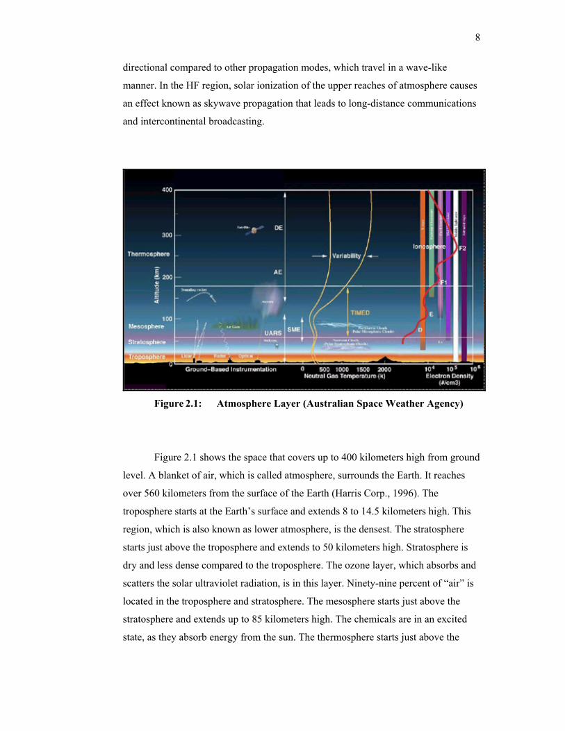
Figure 2.1: Atmosphere Layer (Australian Space Weather Agency)
Figure 2.1 shows the space that covers up to 400 kilometers high from ground
level. A blanket of air, which is called atmosphere, surrounds the Earth. It reaches
over 560 kilometers from the surface of the Earth (Harris Corp., 1996). The
troposphere starts at the Earth’s surface and extends 8 to 14.5 kilometers high. This
region, which is also known as lower atmosphere, is the densest. The stratosphere
starts just above the troposphere and extends to 50 kilometers high. Stratosphere is
dry and less dense compared to the troposphere. The ozone layer, which absorbs and
scatters the solar ultraviolet radiation, is in this layer. Ninety-nine percent of “air” is
located in the troposphere and stratosphere. The mesosphere starts just above the
stratosphere and extends up to 85 kilometers high. The chemicals are in an excited
state, as they absorb energy from the sun. The thermosphere starts just above the
9
mesosphere and extends up to 600 kilometers high. Chemical reactions occur much
faster here than on the surface of the Earth.
For HF communication, the ionosphere is the most important region that
begins at an altitude of about 50 kilometers and extends up to approximately 300
kilometers. The ionosphere is a region of very thin atmosphere. Ionosphere is clearly
a very unpredictable region. HF communication utilizes the ionosphere to enable
long distance communication. During the day, there may be four regions present
called D, E, F1 and F2 regions. Among these regions, only E, F1, sporadic E, and F2
refract HF waves. The conditions of the regions differ from night and day according
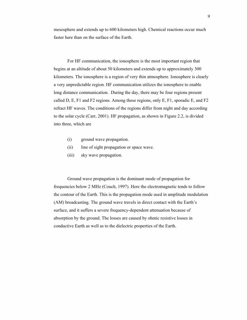
to the solar cycle (Carr, 2001). HF propagation, as shown in Figure 2.2, is divided
into three, which are
(i) ground wave propagation.
(ii) line of sight propagation or space wave.
(iii) sky wave propagation.
Ground wave propagation is the dominant mode of propagation for
frequencies below 2 MHz (Couch, 1997). Here the electromagnetic tends to follow
the contour of the Earth. This is the propagation mode used in amplitude modulation
(AM) broadcasting. The ground wave travels in direct contact with the Earth’s
surface, and it suffers a severe frequency-dependent attenuation because of
absorption by the ground. The losses are caused by ohmic resistive losses in
conductive Earth as well as to the dielectric properties of the Earth.
10
Figure 2.2: Propagation Paths
Line of sight propagation or also known as space wave is the dominant mode
for frequencies above 30MHz (Couch, 1997). Here the electromagnetic wave
propagates in a straight line. The disadvantage of the space wave propagation mode
is for communication between terrestrial stations, the signal path has to be above the
horizon, or else the Earth will block the line-of-sight path.
Skywave propagation is the dominant mode of propagation in the 3~30MHz
frequency range. Here, long distance coverage is obtained by reflecting the wave at
the ionosphere. Skywave propagation is caused primarily by reflection from F layer
(Couch, 1997). Because of this layer, international broadcast stations in HF band can
be heard from the other side of the world at almost any time during day and night.
11
2.2 Effects of Multipath
The advantages of HF communication arise from its relative simplicity, its
ability to provide near global connectivity at low power without relay and its
moderate cost. The apparent disadvantages are directly related to ionospheric
variability. Fading caused by solar disturbances (Goodman, 1992) and multipath
interferences leads to a reduction in reliability in HF communication.
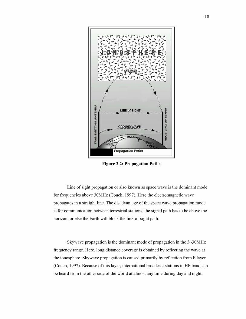
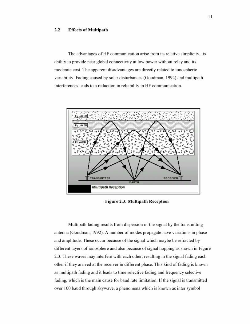
Figure 2.3: Multipath Reception
Multipath fading results from dispersion of the signal by the transmitting
antenna (Goodman, 1992). A number of modes propagate have variations in phase
and amplitude. These occur because of the signal which maybe be refracted by
different layers of ionosphere and also because of signal hopping as shown in Figure
2.3. These waves may interfere with each other, resulting in the signal fading each
other if they arrived at the receiver in different phase. This kind of fading is known
as multipath fading and it leads to time selective fading and frequency selective
fading, which is the main cause for baud rate limitation. If the signal is transmitted
over 100 baud through skywave, a phenomena which is known as inter symbol
12
interference (ISI) will occur. This is where adjacent symbols interfere with each
other. This is caused by time delay spread, which is the main factor in symbol rate
limitation of 100 baud per second (Willink et al, 1996).
Time selective fading is caused by delay due to multipath effect within one
phase. This delay in phase will result in cancellation of waves or attenuation in wave
amplitude. The worst case happens if the same signal from different paths arrives at
the receiver at 0180 phase different, resulting in the wave practically canceling each
other. A delay in milisecond unit due to multipath, introduces a frequency selective
fading to the system. Frequency selective fading will cause certain frequencies to be
attenuated. This in turn will introduce time delay spread problem to the system. So in
order to avoid this problem, symbol transmission rate is limited to 100 baud per
second (Willink et al, 1996).
Doppler shift is caused by the vibration of electrons in the ionosphere layer
(Goodman, 1992). Doppler shift will introduce a change in radio frequency. These
phenomena will cause a problem if the shift in frequency is too great in which the
receiver would not recognize the signal. If the receiver uses a band-pass filter to
capture the signal, the frequency shift will cause the rejection of some of the received
signal. In the case of coherent detection, the received frequency carrier and the
reference frequency at the receiver will be totally different and this will result in the
loss of a whole packet of data.
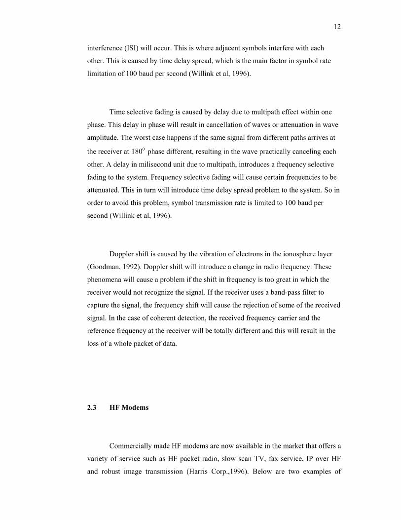
2.3 HF Modems
Commercially made HF modems are now available in the market that offers a
variety of service such as HF packet radio, slow scan TV, fax service, IP over HF
and robust image transmission (Harris Corp.,1996). Below are two examples of
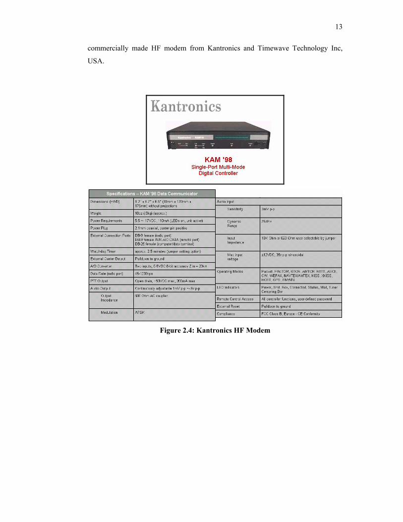
13
commercially made HF modem from Kantronics and Timewave Technology Inc,
USA.
Figure 2.4: Kantronics HF Modem
14
Figure 2.5: Timewave HF Modem
15
2.4 HF Communication Systems
Several types of data format exist in HF communication. They are classed in
the standard format and non-standard format groups. Some of the most frequently
used data formats for standard format group are listed as follows.
(i) RTTY (Baudot code)
(ii) AMTOR (ASCII)
(iii) PACTOR
(iv) PACTOR II
(v) PACTOR III
(vi) GLOVER
(vii) PSK31
(viii) GTOR
Radio Teletypewriter (RTTY) equipment using 5 digits BAUDOT code
became available in the market in the years following World War II (Kasser, 1991).
Radio amateurs experimented using that equipment for communications. RTTY
communication faces a serious problem of fading and noise since error detection is
not used. It is is a half duplex communication mode where a each character is
transmitted as soon as it is typed.
AMTOR is a specialized form of RTTY (Kasser, 1991). The term is an
acronym for Amateur Teleprinting Over Radio and is derived from the commercial
SITOR system (Simplex Telex Over radio) developed primarily for Maritime use in
the 1970s. In the early 1980's, Peter Martinez, G3PLX, made several minor changes
to the SITOR protocol and called it AMTOR. AMTOR improves on RTTY by
incorporating a simple error detection technique. AMTOR employs two forms of
time diversity in ARQ (auto-repeat request) mode and FEC (forward error
correction) mode. A repeat is only sent when requested in ARQ mode whereas in
FEC mode each character is sent twice. In both modes, the redundancy of the code
16
itself which sent at different times, supplies the time diversity in AMTOR (Reed,
2001). AMTOR utilizes ASCII code for transmission. ASCII (American National
Standard Code II) is a coded character set used for information processing systems.
ASCII uses 7 bits to represent letters, figures, symbols and control characters. ASCII
has both upper and lower case letters. The system remains relatively uncomplicated
but AMTOR performs well even in poor HF conditions. While there can still be
many errors in AMTOR data, the error detection helps a lot and the result is quite
tolerable for normal text mode conversations because of the high redundancy in plain
language text. AMTOR is a half duplex communications mode with some of the
attributes of a full duplex mode.
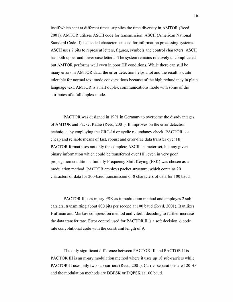
PACTOR was designed in 1991 in Germany to overcome the disadvantages
of AMTOR and Packet Radio (Reed, 2001). It improves on the error detection
technique, by employing the CRC-16 or cyclic redundancy check. PACTOR is a
cheap and reliable means of fast, robust and error-free data transfer over HF.
PACTOR format uses not only the complete ASCII character set, but any given
binary information which could be transferred over HF, even in very poor
propagation conditions. Initially Frequency Shift Keying (FSK) was chosen as a
modulation method. PACTOR employs packet structure, which contains 20
characters of data for 200-baud transmission or 8 characters of data for 100 baud.
PACTOR II uses m-ary PSK as it modulation method and employes 2 sub-
carriers, transmitting about 800 bits per second at 100 baud (Reed, 2001). It utilizes
Huffman and Markov compression method and viterbi decoding to further increase
the data transfer rate. Error control used for PACTOR II is a soft decision ½ code
rate convolutional code with the constraint length of 9.
The only significant difference between PACTOR III and PACTOR II is
PACTOR III is an m-ary modulation method where it uses up 18 sub-carriers while
PACTOR-II uses only two sub-carriers (Reed, 2001). Carrier separations are 120 Hz
and the modulation methods are DBPSK or DQPSK at 100 baud.
17
CLOVER uses a four-tone multi-level modulation system that includes a
combination of frequency, phase and amplitude-shift modulation (Reed, 2001).
CLOVER uses a very low base data rate 31.25 symbols per second to counter the
multipath propagation distortion that commonly occurs on HF radio signals.
Modulation technique, which is used, is BPSK or QPSK. 4 carriers are used in
CLOVER with 125Hz carrier spacing within 500Hz bandwidth. Clover uses Reed-
Solomon error correction codes to correct a moderate number of errors but it can also
switch to ARQ whenever the conditions are very bad and number of error exceeds
the capacity of Reed-Solomon error corrector.
PSK31 stands for phase shift keying, which is the method used for
modulation (Reed, 2001). The precise bit rate for PSK31 is 31.25. PSK31 is designed
based on RTTY mode of operation. The RTTY code shuffles various combinations
of five bits to represent each character. For example, the letter A is expressed as
00011. For a new code called Varicode that combines the best of RTTY and Morse
was designed. In Varicode, shorter codes are allocated to the letters that appeared
most often in standard English text. The idea was to send the least number of bits
possible during a given transmission. For example E is a very popular letter on the
English alphabet hit parade, so it gets a Varicode of 11. Z sees relatively little use, so
its Varicode becomes 111010101.
G-TOR is a completely new hybrid – ARQ HF digital communications
system for commercial and amateur services. Golay error correction coding forms
the basis for G-TOR (short for Golay - TOR), G-TOR is the innovation of
KANTRONICS (Reed, 2001), introduced in 1994. Key features of G-TOR are
extended Golay forward error correction coding, full-frame interleaving, link-
quality-based baud rate (300, 200, and 100), 2.4 second hybrid-ARQ cycle and use of
standard FSK tone pairs (mark and space). Format of G-TOR operation is
proprietary.
18
Several of the non-standard formats are listed as follows (Scalsky, Chace,
1997):
(i) ARQ6-90/98 - 6-character-block simplex ARQ used by French and
Italian Diplomatic services, typically 200 bd. ARQ-6/90 and ARQ-
6/98 differ in their inter data block timing.
(ii) IRA-ARQ - Duplex ARQ with IRA (ITA-5), used by Czech/Slovak
Diplomatic stations, typically 171.42, 200.2, or 300.3 bd.
(iii) PICCOLO - Originally developed in 1957 in Great Britain at the
Diplomatic Wireless Service or as it is known today the
Communication Engineering Department of the British Foreign and
Commonwealth Office (FCO).
(iv) COQUELET - COQUELET Mk I is an asynchronous 13 tone ITA2
system used by French (possibly abandoned) and Belgian military
police. COQUELET Mk II is a synchronous 8 tone ITA2 system used
by Algerian Diplomatic and Customs.
Other than the standard format and non-standard formats listed above, there
are two governing bodies that sets the standard for HF communication. STANAG
5066 is a standard protocol that covers the NATO countries while FED-STD-1052 is
a standard by U.S. Government to ensure the minimum level of interoperability
among HF modems.
The STANAG 5066 is a NATO Standardization agreement: Profile for HF
Radio Data Communications (Trinder, Gillespie, 2001). It is an open standard
defining the requirements for building interoperable HF data communication system.
STANAG 5066 was completed prior to the standardization of high data rate
waveform capable of data rates of 9.6kbps and higher. In addition for ARQ protocol,
the standard includes a mechanism for adapting the data rate in accordance with the
prevailing channel conditions. STANAG 5066 NATO Standardization agreement
targets a very high data transfer rate for military use HF communication system.
19
FED-STD-1052 is a standard by U.S. Government which contains technical
standard for minimum interface and performance standards pertinent to modems
which operate in HF radio equipment (FED-STD-1052; 1994). The general standard
is the HF modems shall be capable of modulating and demodulating serial data
into/from an FSK waveform. The minimum acceptable performance is 75 bps using
the FSK and PSK single-tone waveforms. Modems with 150, 300, 600, 1200, 2400,
all coded and 4800 bps uncoded, should have the capability to adapt to channel
condition. This standard states that FEC encoder shall be used for data rates up to an
including 2400 bps. It proposes the use of ½ code rate for the FEC coding scheme.
2.5 Recent Development in HF Digital Modulation Techniques
Continuous research is conducted in finding the best modulation method to be
used in HF. Among the types that are frequently investigated is the m-ary modulation
method which is capable in transferring high data rate. The best method to
implement error control is also explored where a faster decoding method could
reduce the overall time needed for processing. The effect of different computational
platform is compared to find the trade-off between the speed and power consumption
(Jorgenson et al, 2001).
(Cook, 1993) employs a 16-DQPSK signaling tones at a 75 baud QPSK
modems placed in adjacent channels. The low symbol rates of the tones were chosen
to combat the time delay spread introduced by HF channels, typically in the range of
a few milliseconds. (Nilsson, Timothy, 1997) explored the potential of m-ary or
OFDM for military HF communication. The proposed system uses a differential
binary PSK (DBPSK) modulation method on each carrier. The number of carriers
used in this system is 1024 over a bandwidth of 125 kHz and the symbol duration is
20
8.2ms. The modem proposed by Nilsson is capable of operating until 1.22Mbps.
(Cook et al, 1994) conducted a work on designing a high speed m-ary HF modem.
The modem used 16 tone formats and the modulation method is 8PSK. This modem
could operate for 3.6kbps. (Clark et al, 1993) implemented multi frequency shift
keying (MFSK) in his paper. Maximum number of tones transmitted in his modem
over 2 kHz of bandwidth is 32 tones. Data format used in his approach is the
PICCOLO format. Reed Solomon (RS) code is used as an error correction coding.
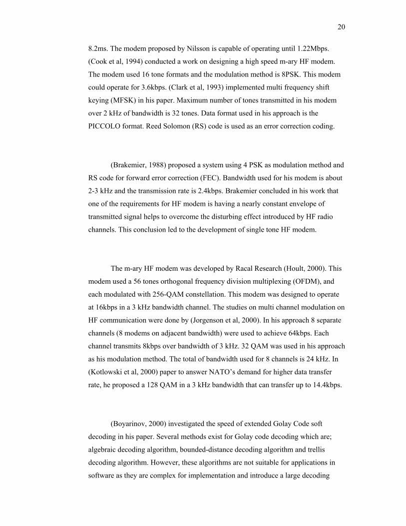
(Brakemier, 1988) proposed a system using 4 PSK as modulation method and
RS code for forward error correction (FEC). Bandwidth used for his modem is about
2-3 kHz and the transmission rate is 2.4kbps. Brakemier concluded in his work that
one of the requirements for HF modem is having a nearly constant envelope of
transmitted signal helps to overcome the disturbing effect introduced by HF radio
channels. This conclusion led to the development of single tone HF modem.
The m-ary HF modem was developed by Racal Research (Hoult, 2000). This
modem used a 56 tones orthogonal frequency division multiplexing (OFDM), and
each modulated with 256-QAM constellation. This modem was designed to operate
at 16kbps in a 3 kHz bandwidth channel. The studies on multi channel modulation on
HF communication were done by (Jorgenson et al, 2000). In his approach 8 separate
channels (8 modems on adjacent bandwidth) were used to achieve 64kbps. Each
channel transmits 8kbps over bandwidth of 3 kHz. 32 QAM was used in his approach
as his modulation method. The total of bandwidth used for 8 channels is 24 kHz. In
(Kotlowski et al, 2000) paper to answer NATO’s demand for higher data transfer
rate, he proposed a 128 QAM in a 3 kHz bandwidth that can transfer up to 14.4kbps.
(Boyarinov, 2000) investigated the speed of extended Golay Code soft
decoding in his paper. Several methods exist for Golay code decoding which are;
algebraic decoding algorithm, bounded-distance decoding algorithm and trellis
decoding algorithm. However, these algorithms are not suitable for applications in
software as they are complex for implementation and introduce a large decoding

21
delay. Boyarinov introduced decoding algorithm, based on Turyn construction,
which is capable in correcting all triple and fewer errors. This decoder still requires
an extensive computation since it requires at least 80 operations to calculate the
initial syndromes to determine there are no errors present. (Cook, 1993) did a study
to find the best error-control options for HF modems. He investigated six error
control coding schemes and he concluded that Trellis coded modulation (TCM) is the
most suitable for an m-ary (16 sub-carrier) 2.4kbps HF modem.
Considerable work is done to investigate the appropriate platform of HF
modem. Converting the computer to be the HF software modem may not be the
correct solution in some cases. (Jorgenson, 2001) proved that a PC that runs on
processors before Pentium III processor may not be capable in handling the real-
time calculation for the signal processing. Jorgenson compared the interrupt latencies
and thread latencies between a PC running on NT OS and Linux OS and
Jorgenson concluded that PC running on Linux OS performs better. A comparison
between PC software modem and modem implemented on DSP board are also
compared. DSP processors are at an advantage where its power consumption is low
compared to multi purpose processor such as Pentium. Power consumption for DSP
processor such as Texas Instrument TMS320VC5416 DSP boards at full operation is
only 100 mWatt (TMS320VC5416 Technical Reference), whereas Pentium drained
about 10 to 100 Watt for it to be fully operational (Blonstein, Katorgi, 2003).
Relative to advance DSPs, general purpose processors like Pentium are high in
power consumption. However, DSPs have an obvious disadvantage compared to PC
software modem. The programmers are faced with a very limited internal memory
during modem implementation on DSP boards.
2.6 Cryptography
Cryptography is the science of information security (Nichols and Lekkas,
2002). It is the technology that encodes information so that only accessible by
22
authorized parties. In the modern computer world, cryptography is commonly
associated with encryption and decryption where encryption refers to scramble
ordinary data called plaintext into cipher text and decryption means the vice versa.
According to the Federal Standard 1037C: Glossary of Telecommunications Terms,
cryptography is defined as “The principles, means and methods for rendering plain
information unintelligible and for restoring encrypted information to intelligible
form” (Federal Standard 1037C, 2002). It is closely related to the disciplines of
cryptography and cryptanalysis.
There are 4 major objectives of modern cryptography:
(i) Confidentiality: ensures only authorized parties can access the
information. The standard mechanism for enabling confidentiality is
encryption.
(ii) Authentication: ensures both sender and recipient can confirm each
other’s identity. There are many authentication mechanism exist, for
example presenting user ID and password, using smart card, digital
signatures, biometric authentication and challenges and response
authentication.
(iii) Integrity: ensures no altering can be made to information without
being detected. The alterations include but not limit to change, delete
and create. Message digests are the primary mechanism for ensuring
data integrity.
(iv) Non-repudiation: ensures neither the sender nor the recipient can
deny his intentions in the transmission of the information. Digital
signatures are the basic non-repudiation enabling mechanism.
Procedures and protocols that meet some or all of the above criteria are
known as cryptosystems or cipher system. These systems are not only refer to
mathematical procedures and computer programs, in fact, it includes the regulation
of human behavior such as choosing hard-to-guess password, frequently change of
passwords, logging off unused systems and not discuss sensitive procedures with
outsiders.
23
Now, cryptography is a very important field especially in communication and
banking system. It is also a crucial factor to success in war or business as well. Due
to this significant, there are many parties who attempt to design new cipher system in
order to improve an existing system. They are not only creating better cipher systems
that tends to be more difficult to be hacked but they are also trying to hack the
existing cipher systems in order to discover the weaknesses and further strengthen it.
Referring to Federal Standard 1037C, the cryptology is “the science that deals
with hidden, disguised or encrypted communications. It embraces communications
security and communication intelligence” (Federal Standard 1037C, 2002). It is the
science of mathematics, such as number of theory and the application of formulas
and algorithms that underpin cryptography and cryptanalysis.
Cryptanalysis refers to the study of cipher systems, either the algorithms and
procedures or the cipher-text, with the sole objective to find weaknesses in them that
will permit retrieval of the plaintext from the cipher-text, without necessarily
knowing the key or the algorithms. This is known as breaking the cipher systems. It
includes the weakening strategy that find a property or fault in the design or
implementation of the cipher that reduces the number of keys required to facilitate
others attack such as a brute force attack.
There are numerous techniques for performing cryptanalysis, depending on
the access to the plaintext, cipher text, or other aspects of the cipher systems
(Stallings, 2003). These include:
(i) Cipher-text-only analysis
(ii) Adaptive chosen-plaintext analysis
(iii) hosen-cipher text analysis
(iv) Meet-in-the-middle attack
24
(v) Timing or differential power analysis
(vi) Slide attack cryptanalysis
(vii) Differential cryptanalysis
(viii) Linear cryptanalysis
Besides these electronics programmable methods, there are some other
unorthodox techniques such as convincing individuals to reveal password or keys,
developing Trojan horse programs to steal secret key or tricking a victim into using a
weakened cipher systems.
2.7 Cipher Systems
Cipher system is the system that encrypts and decrypts data. Generally, there
are two kinds of cipher systems, which are symmetric and asymmetric. The
symmetric or the secret key cipher system uses the same key in encryption and
decryption. Asymmetric or the public key cipher systems uses one key to encrypt and
the other corresponding key to decrypt. Usually, a cipher system comprises 5
elements: the plaintext, cipher text, key, encryption and decryption functions
(Nichols and Lekkas, 2002).
2.7.1 Symmetric Cipher Systems
Symmetric Cipher systems use the same key for encryption and decryption. It
is often referred to as secret-key cipher systems or conventional cipher systems (Lail,
2002). Generally, the symmetric cipher systems are algorithms that use the
underlying transposition and substitution operation, to ensure that cipher-text can
only be decrypted by the corresponding secret key.
25
The core security factor for symmetric cipher systems is the encryption
algorithm. It must be powerful enough so that it is impossible to decrypt a message
based on the cipher-text alone. Secondly, the security depends on the secrecy of the
key, and not the algorithm. Thus we are not required to keep algorithm secret.
Symmetric cipher systems have a few common disadvantages (Kotsakis,
2004). First, it is impossible for the sender of the message to prove to his partner that
he has sent a particular message. Secondly, the keys have to be communicated on a
channel whose cryptanalytic security is much higher than the security of the channel
used for normal transmission. With a large number of partners wanting secure
communication, the number of two-way channels and thus the number of keys
becomes quite large. This is because for a network with N parties, when each
wanting to exchange messages safely with everyone, total of N*(N-1)/2 keys are
required (Stallings, 2003). For example, in the network of 10 persons, total of 45
keys are required and kept on each party. However, these disadvantages can be
overcome by using suitable authentication and key distribution technique.
On the other side, as comparatively to asymmetric cipher systems, symmetric
cipher systems can process data faster. Thus a lot of applications in the market today
use an asymmetric system to exchange secret keys at initial stage, and then use a
symmetric system to transport data (Kotsakis, 2004).
There are two types of symmetric algorithms, which are stream ciphers and
block ciphers. Examples of symmetric cipher systems are Data Encryption Standard
(DES) (Stallings, 2003), Advanced Encryption Standard (AES) (NIST, 2001),
Blowfish, Twofish, IDEA, CAST, SEAL and RC4. Among these, RC4 (Schneier,
1996) and SEAL (Menezes et al., 1996) are the stream ciphers and the rest are block
ciphers.
26
2.7.1.1 Block Cipher
A block cipher is a method of encrypting text in which a cryptographic key
and algorithm are applied to a fixed length block of data at once rather than to one bit
at a time (Pawliw, 2001). The fixed length is called the block size. A block cipher
effectively provides a permutation of the set of all possible messages as different
plaintext blocks are mapped uniquely to different cipher-text blocks. The
permutation effected during any particular encryption is the function of the secret
key. Block cipher utilize both diffusion and confusion criteria. Diffusion means
every block or character of the cryptogram is dependent on each other. Every single
bit is dependency, which causes an error in block size. The cryptogram generated by
block cipher also random and unpredictable which is called confusion. By make use
these criteria, the block cipher has high resistant in security.
There are three basic important behaviors of block ciphers (Pawliw, 2001):
(i) Knowing both the plaintext block and the key, it must be easy to
calculate the cipher-text block
(ii) Knowing both the cipher-text block and the key, it must be easy to
calculate the plaintext block
(iii) Knowing both plaintext block and the cipher-text block, it must be as
difficult as possible to find the key
There are a lot of cryptanalysis theories and practices relevant to block
ciphers that have been published such as differential cryptanalysis, linear
cryptanalysis (Schneier, 1996), slide attack cryptanalysis and algebraic cryptanalysis
(Menezes et al., 1996). For a modern proposal for a block cipher to be taken
seriously, there must be a good reason to believe it is strongly resistant to all these.
Examples of popular block ciphers include AES and DES. AES is the
replacement of the DES certificate by National Institute of Standards and
27
Technology (NIST). Another block ciphers that have been published are Twofish,
Serpent, RC6, RC5, Safer, IDEA, Blowfish (Stallings, 2003), and GOST (Schneier,
1996).
2.7.1.2 Stream Cipher
Stream ciphers encrypt input data one bit (sometimes one byte) at a time
(Beker and Piper, 1982). They are also called state ciphers, as the encryption of a bit
is dependent on the current state. The encryption and decryption process of stream
ciphers normally involves the exclusive-OR (XOR) operation of the plaintext with
the keystream to produce the ciphertext. Keystream generally consist of a
pseudorandom bit pattern, such as the output of a pseudorandom number generator
(PRNG). Key or password is then used to generate a seed for the PRNG in order to
generate same keystream in encryption and decryption.
Generally, stream ciphers can be designed to be exceptionally faster to
execute in hardware than block ciphers. Another important feature is a single bit of
cipher text error results in a single bit of plaintext error, which is very useful when
the transmission error rate is high. In order to provide high security, a stream cipher
needs all these characteristics (Beker and Piper, 1982)
(i) A cryptogram must have random characteristics
(ii) A keystream must have high linear complexity
Examples of stream ciphers are RC4, Shrinking, Improve Geffe, SEAL
(Menezes et al., 1996), SNOW (Ekdahl and Johansson, 2001) and SOBER (Rose,
2000).
28
2.7.2 Comparison between block and stream cipher system
Even though both block and stream ciphers need same secret key to encrypt
and decrypt, but obviously the processing is different. Block cipher encrypts the
plaintext by blocking, usually 64 bits or 128 bits respectively depends on algorithms
but stream cipher encrypts the plaintext bit by bit. Block cipher utilizes both
diffusion and confusion and is not for stream cipher, which only had confusion
criteria. Because of that, block cipher suitable to be used in key management,
authentication and encryption while stream cipher only for encryption (Schneier,
1996).
Actually, the choice between using block cipher or stream cipher is greatly
affected by its application. The usage of block cipher implies error propagation.
Thus, block ciphers can only be used when error propagation is either an advantage
or, at least, not a handicap (Tuan Sabri, 1995). The example where the block cipher
often used for encryption is in banking system and Internet service (Lail, 2002).
However, in any communication over a noisy channel such as high frequency
medium, an introduction of extra errors because of encryption is unacceptable. For
block cipher, an introduction of error in transmission causes propagation error. Even
though there is an error correction to handle error in transmission, but it is still not
guarantee. Due to no propagation error produce, a stream cipher is better choice
rather than a block cipher.
29
2.7.3 Asymmetric Cipher systems
The asymmetric or the public key cipher system uses one key to encrypt and
other corresponding key to decrypt. It was found and published by Whitfield Diffie
and Martin Hellman (Diffie and Hellman, 1976), although the National Security
Agency (NSA) claims to have discovered it some years earlier. This system makes
use of various intractable mathematics problems, that are normally easy to calculate
from one way, but theoretically almost impossible to compute the original value from
the results, which is the other way. These problems include discrete logarithm
problem, the integer factorization problem and elliptic curve discrete logarithm
problem. Asymmetric cipher systems allow public keys to be simply distributed to
the public. Data that is encrypted using the published public key can only be
decrypted using the secure private key kept secretly by individuals. The computation
of one key from the other key is infeasible. Some examples of asymmetric cipher
systems are Digital Signature Standard (DSS), RSA, El-Gamal and Diffie-Hellman
(DH) (Stallings, 2003).
2.8 Advanced Encryption Standard (AES)
On December 6th 2001, the Secretary of Commerce, United State (US)
officially approved FIPS 197, which specifies that all sensitive, unclassified
documents will use Rijndael as the Advanced Encryption Standard (AES). AES in
fact is the result of the NIST effort to find a more robust replacement for DES and to
a lesser degree Triple DES (Stallings, 2003). In January 1997, NIST has initiated a
call for symmetric cipher algorithm that uses 128-bit block size, supporting key sizes
of 128, 192 and 256 bits as a minimum. The algorithm was required to be royalty-
free for use worldwide and offered security of a sufficient level to protect data for the
30
next 20 to 30 years. It was to be easy to implement in various types of hardware and
software, offer good defenses against various attack techniques.
The entire selection process was fully open to public scrutiny and comment;
it had being decided that full visibility would ensure the best possible analysis of the
designs. In August 1999, NIST selected five algorithms for more extensive analysis,
which were: MARS from IBM research, RC6 by RSA Security, Rijndael by two
Belgian Cryptographers, Joan Deamen and Vincent Rijment, Serpent by Ross
Andersen, Eli Biham and Lars Knudsen, and Twofish submitted by researchers
including Counterpane’s respected cryptographer, Bruce Schneier. The end result
was that on October 2, 2000, NIST announced that Rijnadael had been selected as
the proposed standard.
Rijndael was initially developed to support variable block length and key
length, and they can be extended very easily to multiples of 32 bits. The design of
Rijndael was strongly influenced by the design of the block cipher square.
The new AES cipher (NIST, 2001) is fast in both software and hardware,
relatively easy to implement and requires little memory. As the new block cipher
standard it is currently being deployed on a large scale. AES has 10 rounds for 128-
bit keys, 12 rounds 192-bit keys and 14 rounds for 256-bit keys. It is very fast,
almost approaching the speed of existing hashing algorithm, nonetheless faster than
DES and Triple DES.
2.9 Authentication, Key Distribution and Confidentiality
Authentication is a basic security services, without it most other
communication security services become meaningless. This mechanism will enable
31
both parties to verify the authenticity of message or user as well. The authentication
can be grouped into three classes, as follows:
(i) Message encryption: The cipher text of the entire message serves as
its authenticator
(ii) Message authentication code (MAC): A public function of the
message and a secret key that produces a fixed-length value that
serves as the authenticator.
(iii) Hash function: A public function that maps the message of any
length into fixed-length hash value, which serves as the authenticator
One of the popular methodologies for authentication, which is used in many
applications, is challenge and response authentication (Menezes et al., 1996). In
general, this method can be implemented either using symmetric or public key cipher
system as long they provide an authenticity as well. Symmetric is best for encrypting
data, while public key is best for key management (Schneier, 1996). Secured HF
Transmission System is an example of communication system where the users
coming from specific parties. Therefore, the user network is not complex as ordinary
network-based station. So, the block cipher is chosen due to fewer burdens of key
management, faster encryption time and less complex of implementation. Figure 2.6
shows the diagram of challenge and response authentication using block cipher
Advanced Encryption Standard (AES) with 256 bits.
32
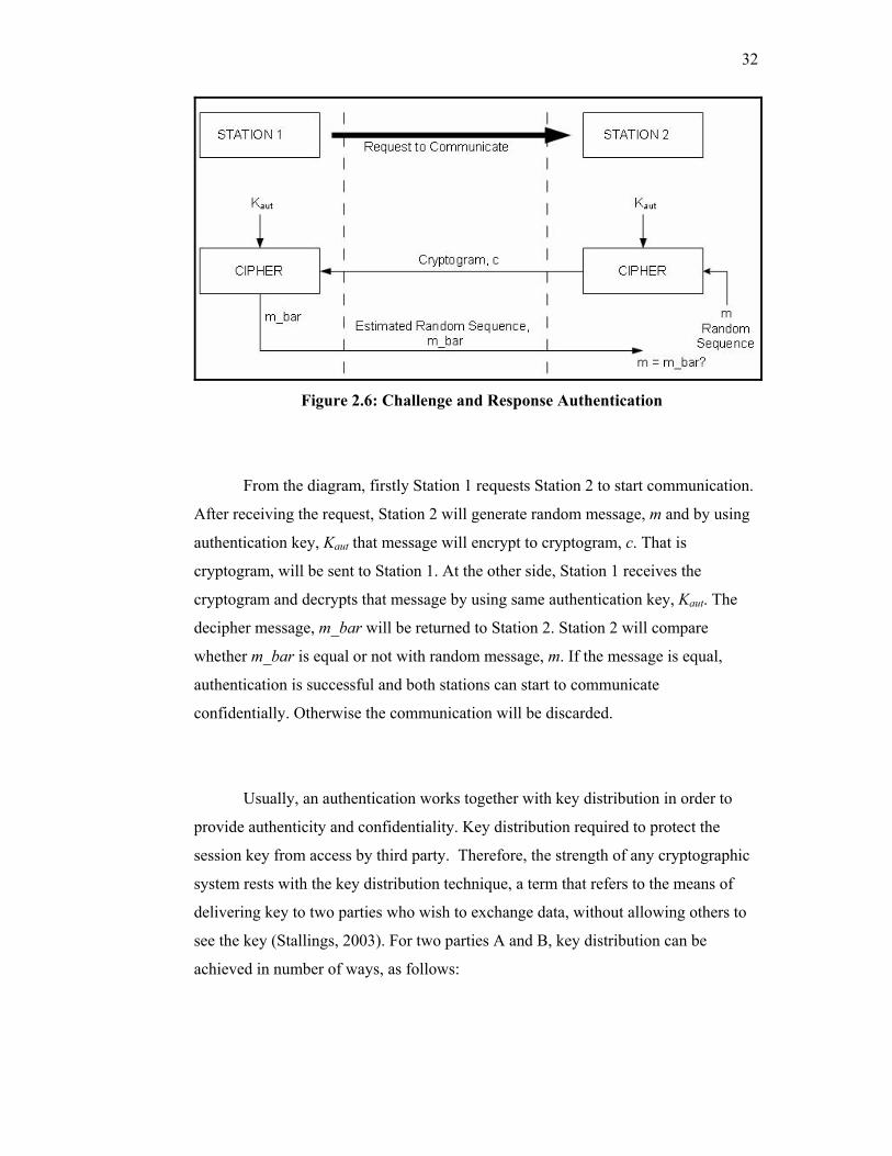
Figure 2.6: Challenge and Response Authentication
From the diagram, firstly Station 1 requests Station 2 to start communication.
After receiving the request, Station 2 will generate random message, m and by using
authentication key, Kaut that message will encrypt to cryptogram, c. That is
cryptogram, will be sent to Station 1. At the other side, Station 1 receives the
cryptogram and decrypts that message by using same authentication key, Kaut. The
decipher message, m_bar will be returned to Station 2. Station 2 will compare
whether m_bar is equal or not with random message, m. If the message is equal,
authentication is successful and both stations can start to communicate
confidentially. Otherwise the communication will be discarded.
Usually, an authentication works together with key distribution in order to
provide authenticity and confidentiality. Key distribution required to protect the
session key from access by third party. Therefore, the strength of any cryptographic
system rests with the key distribution technique, a term that refers to the means of
delivering key to two parties who wish to exchange data, without allowing others to
see the key (Stallings, 2003). For two parties A and B, key distribution can be
achieved in number of ways, as follows:
33
(i) A can select a session key and physically deliver it to B.
(ii) A third party can select the session key and physically deliver it to A
and B.
(iii) If A and B have master key, one party can transmit a session key to
the other, encrypted using master key. This also called decentralized
key distribution.
(iv) If A and B each has an encrypted connection to a third party C, C can
deliver a session key on the encrypted links to A and B. This method
is called centralized key distribution.
Due to Secured HF Transmission System where both stations are far away
and using end-to-end encryption, manual delivery of session key is awkward. Here
session key will change rapidly depending on the number of stations involve and
communication had occurred. Therefore, session key supplied should be
dynamically, and the solution of this is using decentralized key distribution
technique.
Because the trusted third party is not involve directly in communication, both
parties need master key which is consist authentication key and session key
distribution key. The master key management is handled or programmed by trusted
third party (Mils, 2004). By using master key, session key is distributes using block
cipher AES 128 bits. The rest of the communication than occurs confidentially using
a proprietary stream cipher. The security of Secured HF Transmission System was
provided based on symmetric cipher system which need both parties have same
secret key. In practice, GSM communication also uses symmetric cipher system
where A3 block cipher used for authentication and A5 stream cipher for
confidentiality (Quirke, 2004).
34
2.10 Examples of application for HF transmission system
HF e-mail systems such as Sail Mail (SailMail, 2004), and Cruise email
(Cruiseemail, 2004) are capable for data transmission via HF medium and now
available in the market. Both commercial systems also support the messaging system
but unfortunately they do not have features for authenticity and confidentiality. They
are needed because the HF medium is free and low cost of infrastructure setup
compare with satellite system. By using the advances in High Frequency radio, these
systems can be sent and received in the most remote areas. Besides, the
communications is easy and transparent to the user because the users have complete
controls of the radio and modem.
EasyTransfer is another system developed by SCS PC Software that allowed
the communication via HF medium (Pactor, 2004). EasyTransfer (for Win98 and
above) is a program developed for binary file transfers between two computers and it
is using PACTOR coding for data transmission. The graphical user interface is
similar to some well-known FTP clients, which are used for file transfers via the
Internet. In addition to the file transfer, EasyTransfer has a chat mode to exchange
hand typed messages. With that, EasyTransfer is the ideal tool to exchange digital
information over unlimited distances through HF medium.
The Winlink 2000 (WL2K) radio-email digital network system is the
software that is capable to extend with the amateur radio to provide data transmission
over HF medium (Winlink, 2000). It was developed by Winlink Development Team
to assist the mobile or remotely located user, and to provide emergency email
capabilities to community agencies. Because of this, WL2K supports a clean simple
interface to the Internet SMTP e-mail system. Using own B2F format, any message
sent or received may include multiple recipients and multiple binary attachments.
The radio user's email address, however, must be known to the system as a radio user
or the message will be rejected. This simple Internet interface protocol has an added
benefit in case of an emergency where local services are interrupted and the system
35
can use by non-Amateur groups as an alternative to normal SMTP email. Connecting
to any one of the WL2K publicly used PMBOs (Participating Network Stations) via
HF (radio) or the specialized non-public PMBOs, can immediately and automatically
connect a local amateur station to the Internet for emergency traffic. Using MS
Outlook or MS Outlook Express, the Paclink mini-email server can replace a
network of computers (behind a router) as a transparent substitute for normal SMTP
mail (Winlink, 2000). WL2K uses no external source for sending or receiving
Internet email. It is a stand-alone function, which interacts directly with the internet
rather than through any external Internet service provider.
Communication through HF medium whether using email or messaging
system is still not perfect without having security features. It is important to make the
communication with authentication, confidential and integrity. Primarily, security to
the military is to avoid their enemy from getting the secret information. Second
entities that need this feature in their system are anyone that involved in business.
This is because they need to protect their asset or secret information from their
business competitor. Some of the messaging systems that had security features are
System 700 that is produced by Mils Electronic (Mils, 2004), HC-6830 by Crypto
AG (Crypto AG, 2004) and HF Email from Reids Radiodata (Reidsradiodata, 2004).
The Mils Electronic System 700 is not the only one to support messaging
system but also others in communication like GSM, E-mail, HF radio and Telex. The
M730 Cipher Machine handles the cipher function of this system. This is a Windows
application for processing messages at a station of the System 700 network.
Everything about encrypting and decrypting of messages, sending and receiving of
ciphered messages and the administration of these messages happened here. A
proprietary stream cipher algorithm encrypts and decrypts the messages. M730 also
provides an authentication algorithm to provide authentication functions.
The Crypto AG HC-6830 is a secure, state-of-the- art, fully ruggedized field
communication station. It combines local security with secure communication via
36
telephone or radio modem at the tactical and strategic levels. Special attention has
also been paid to HF communication by integrating a very compact HF radio modem
into the HC-6830. Due to its versatile design, it may be used for stationary, portable,
vehicular, air-borne, ship borne and man packs applications. The unit provides secure
message handling primarily for army, air force, navy, and military intelligence
organizations and also non-military users such as police forces, international field
organizations and diplomatic. As the HC-6830 is fully modular, the system may be
upgraded at any time to accommodate future applications.
The HF Email produced by Reids Radiodata is distinguishing from the other
commercial product. Unlike Sail Mail and Cruise email, this HF Email supported
with the compression and security service to make the data transmission faster and
secure (Reidsradiodata, 2004). This Reids Radio Data HF Email service gives us our
own email address such as [email protected] so anyone anywhere in the
world can send an email to us, all we need to do is connect to the email server and
our email will automatically be downloaded to computer.
Finally, the HF Messenger™ (Soyer, 2001) created by Rockwell-Collins,
France is advanced HF data communication software. It implements the NATO
STANAG 5066 standard and uses Q9600 modem device implementing the MIL-
STD-188-110B waveform and equipped with ALE capability. Besides, this system
also provides stream cipher algorithm to ensure the transmission occurred secure.
The main objective of this system is to permit personal computers to exchange text,
files, facsimiles, images and pictures at data rates equivalent to current satellite
radios over a HF medium. This system also provides wireless transmission between
several HF users for broadcasting, multicasting or point-to-point with services in
LAN operating environment. The main application offered by this system is HF e-
mail for ground, tactical airborne and maritime.
37
2.11 Telemetry
SCADA is an acronym for Supervisory Control and Data Acquisition. As the
name indicates, it is not a full control system but more focuses on the supervisory
level or in other words telemetry or remote monitoring. One of the advantages of
implementing the SCADA system is it has databases system that allows information
collection, sharing and offline analysis. SCADA system is used in industrial and
engineering applications to monitor and control distributed station remotely from a
master location. Therefore, SCADA system usually covers a large geographical
area.
A SCADA system consists of three main components, which are the field
data interface devices or a Remote Telemetry/Terminal Unit (RTU), the
communication medium, and human-machine interface or Graphical User Interface
(GUI). A SCADA system gathers information at remote stations, transmit back the
information to master station through a communication medium and display the
information in organized fashion and store information in database to allow future
analysis.
2.11.1 Tanjung Tuan Lighthouse VHF Telemetry
Lighthouse telemetry is an example of SCADA system. A visit to Tanjung
Tuan Lighthouse, Port Dickson was conducted to understand a SCADA system in
practical application. Tanjung Tuan Lighhouse has been equipped with electric
distribution line. A generator set is used as back up power source. Main light is the
ac lamp that will only transmit white light when supplied with rated current. Motor is
used to rotate pedestal in a fixed velocity to provide a flashing fog signal. Photo
38
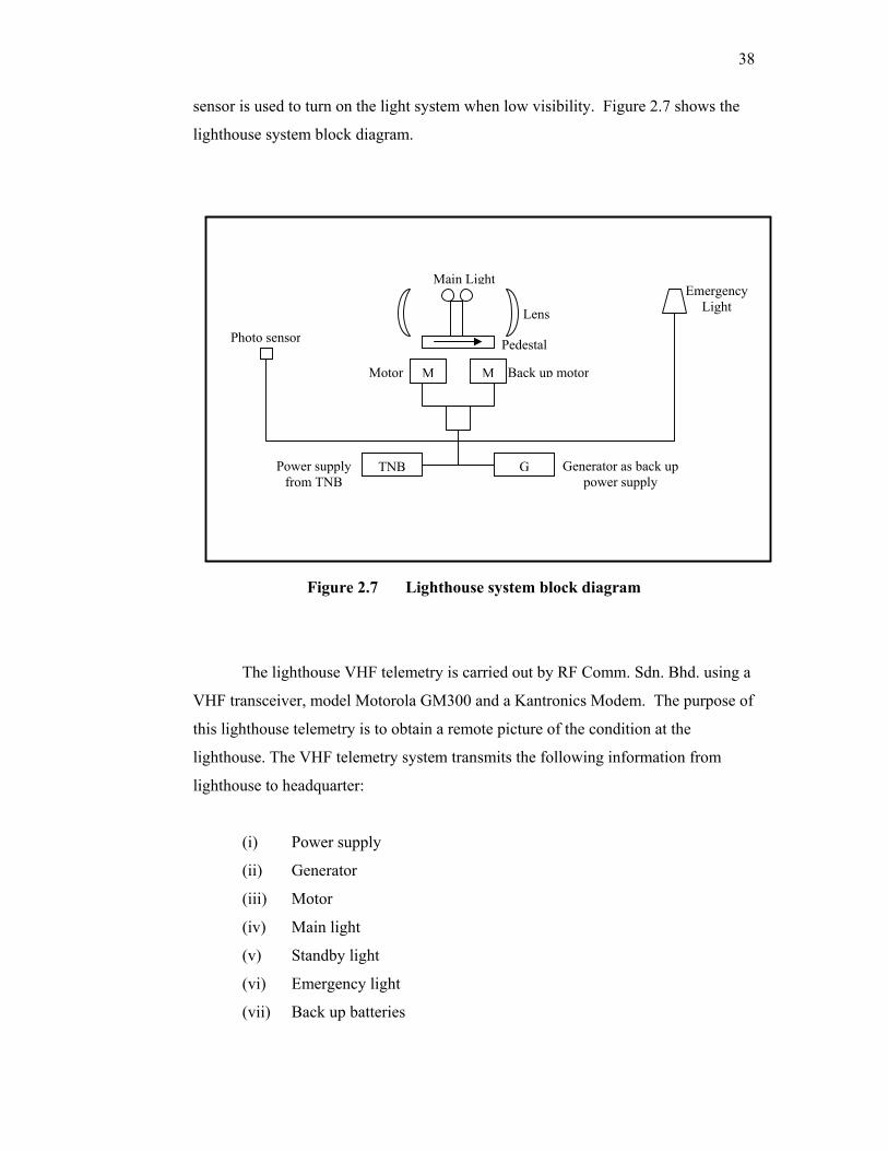
sensor is used to turn on the light system when low visibility. Figure 2.7 shows the
lighthouse system block diagram.
Figure 2.7 Lighthouse system block diagram
The lighthouse VHF telemetry is carried out by RF Comm. Sdn. Bhd. using a
VHF transceiver, model Motorola GM300 and a Kantronics Modem. The purpose of
this lighthouse telemetry is to obtain a remote picture of the condition at the
lighthouse. The VHF telemetry system transmits the following information from
lighthouse to headquarter:
(i) Power supply
(ii) Generator
(iii) Motor
(iv) Main light
(v) Standby light
(vi) Emergency light
(vii) Back up batteries
Motor M M
GTNB
Emergency Light
Main Light
Lens
Pedestal
Back up motor
Photo sensor
Generator as back up power supply
Power supply from TNB
39
From SCADA system, any problem at the lighthouse can be trace and further
action can be made immediately.
2.12 Conclusion
HF communication is important as an alternative for long distance
communication due to low cost equipment setup and being completely under national
control. With the present technology in digital signal processing, advance
communication and adaptive radio technology, digital information is not only
possible to be transmitted over HF radio but also more reliable and error free
transmission. Security features such as authentication and confidentiality will ensure
that only the authorized parties communicate with confidence not to unauthorized
third parties. By understanding the existing system in market and technology behind
it, the proposed system will develop to achieve the objective to exchange an image
over HF radio.
CHAPTER 3
STREAM CIPHER ANALYSIS
The broadcast nature radio of communications such as in the HF (High
Frequency) spectrum exposes the transmitted information to unauthorized third
parties. Employing cipher system ensures confidentiality. For bulk transmission of
data, stream ciphers are ideal choices over block ciphers due to the faster
implementation speed and do not introduce error propagation. Thus, this chapter will
describe the theory of stream cipher algorithm, which contains linear feedback shift
register (LFSR) and nonlinear combining function. By using a common key length
and worst-case conditions, the strength of several stream cipher algorithms are
evaluated based on statistical tests, correlation attack, linear complexity profile and
nonstandard test. The best algorithm is the one that exceeds all of the tests.
3.1 Stream Cipher
The stream cipher (Beker and Piper, 1982) is a symmetric cipher that is
described in Figure 3.1. Unlike the block cipher, the stream cipher enciphers the
plaintext one bit at a time and only utilizes the confusion characteristics not diffusion
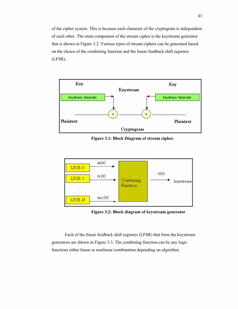
41
of the cipher system. This is because each character of the cryptogram is independent
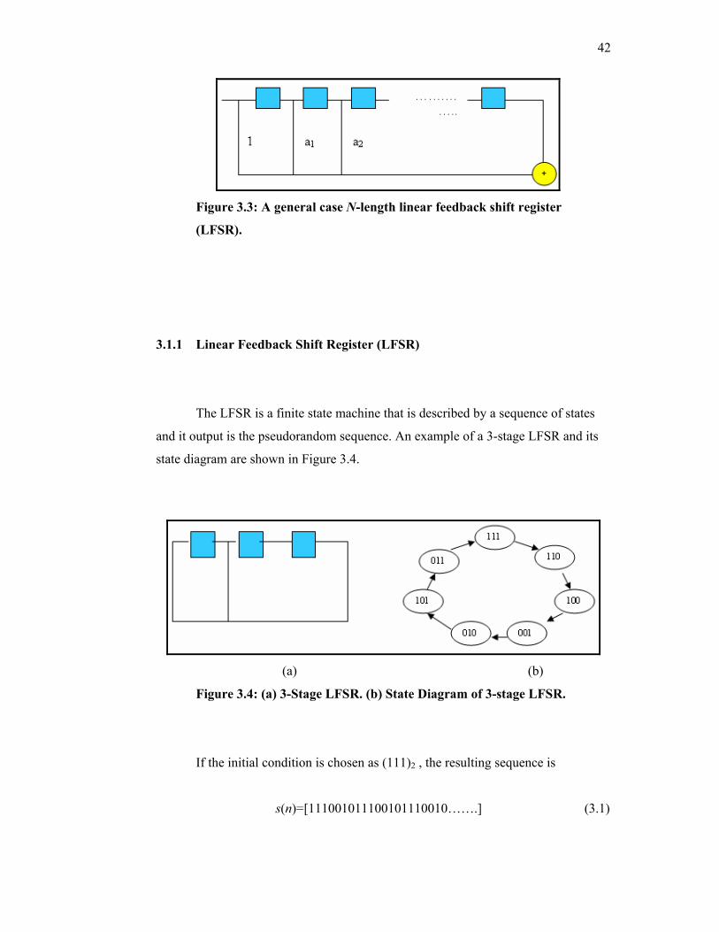
of each other. The main component of the stream cipher is the keystream generator
that is shown in Figure 3.2. Various types of stream ciphers can be generated based
on the choice of the combining function and the linear feedback shift registers
(LFSR).
Figure 3.1: Block Diagram of stream cipher.
Figure 3.2: Block diagram of keystream generator
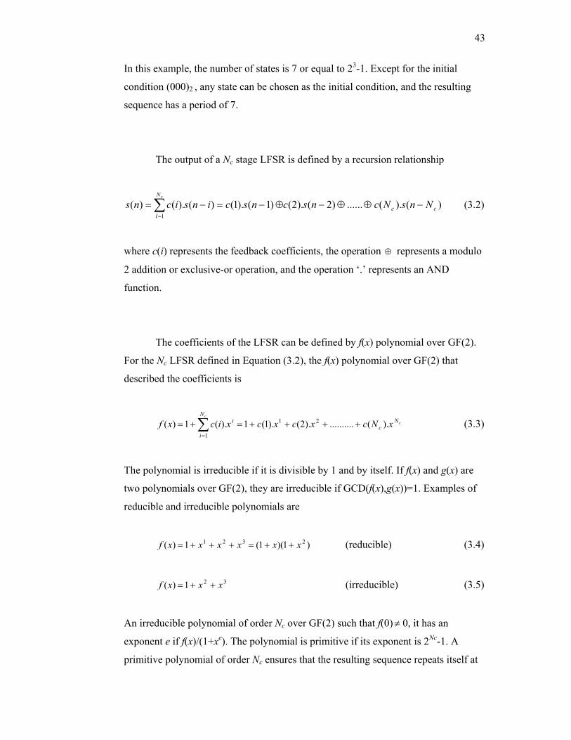
Each of the linear feedback shift registers (LFSR) that form the keystream
generators are shown in Figure 3.3. The combining function can be any logic
functions either linear or nonlinear combination depending on algorithm.
42
Figure 3.3: A general case N-length linear feedback shift register
(LFSR).
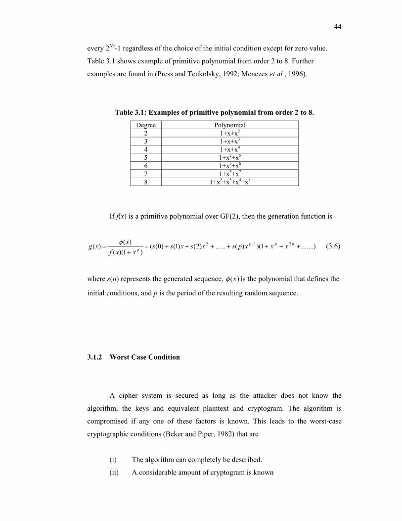
3.1.1 Linear Feedback Shift Register (LFSR)
The LFSR is a finite state machine that is described by a sequence of states
and it output is the pseudorandom sequence. An example of a 3-stage LFSR and its
state diagram are shown in Figure 3.4.
(a) (b)
Figure 3.4: (a) 3-Stage LFSR. (b) State Diagram of 3-stage LFSR.
If the initial condition is chosen as (111)2 , the resulting sequence is
s(n)=[111001011100101110010…….] (3.1)
43
In this example, the number of states is 7 or equal to 23-1. Except for the initial
condition (000)2 , any state can be chosen as the initial condition, and the resulting
sequence has a period of 7.
The output of a Nc stage LFSR is defined by a recursion relationship
)().(......)2().2()1().1()().()(1
cc
N
lNnsNcnscnscinsicns
c
−⊕⊕−⊕−=−= ∑=
(3.2)
where c(i) represents the feedback coefficients, the operation ⊕ represents a modulo
2 addition or exclusive-or operation, and the operation ‘.’ represents an AND
function.
The coefficients of the LFSR can be defined by f(x) polynomial over GF(2).
For the Nc LFSR defined in Equation (3.2), the f(x) polynomial over GF(2) that
described the coefficients is
cc
Nc
iN
i
xNcxcxcxicxf ).(..........).2().1(1.)(1)( 21
1
++++=+= ∑=
(3.3)
The polynomial is irreducible if it is divisible by 1 and by itself. If f(x) and g(x) are
two polynomials over GF(2), they are irreducible if GCD(f(x),g(x))=1. Examples of
reducible and irreducible polynomials are
)1)(1(1)( 2321 xxxxxxf ++=+++= (reducible) (3.4)
321)( xxxf ++= (irreducible) (3.5)
An irreducible polynomial of order Nc over GF(2) such that f(0)≠ 0, it has an
exponent e if f(x)/(1+xe). The polynomial is primitive if its exponent is 2Nc-1. A
primitive polynomial of order Nc ensures that the resulting sequence repeats itself at
44
every 2Nc-1 regardless of the choice of the initial condition except for zero value.
Table 3.1 shows example of primitive polynomial from order 2 to 8. Further
examples are found in (Press and Teukolsky, 1992; Menezes et al., 1996).
Table 3.1: Examples of primitive polynomial from order 2 to 8.
Degree Polynomial 2 1+x+x2
3 1+x+x3
4 1+x+x4
5 1+x2+x5
6 1+x5+x6
7 1+x3+x7
8 1+x2+x3+x4+x8
If f(x) is a primitive polynomial over GF(2), then the generation function is
.......)1)()(......)2()1()0(()1)((
)()( 212 +++++++=+
= − pppp xxxpsxsxss
xxfxxg φ (3.6)
where s(n) represents the generated sequence, )(xφ is the polynomial that defines the
initial conditions, and p is the period of the resulting random sequence.
3.1.2 Worst Case Condition
A cipher system is secured as long as the attacker does not know the
algorithm, the keys and equivalent plaintext and cryptogram. The algorithm is
compromised if any one of these factors is known. This leads to the worst-case
cryptographic conditions (Beker and Piper, 1982) that are
(i) The algorithm can completely be described.
(ii) A considerable amount of cryptogram is known
45
(iii) There is certain amount of cryptogram and its equivalent plaintext
available.
For the first condition, the only security that can be provided by algorithm is
in the key length. Attack based on an exhaustive keysearch of all the possible keys
should not be possible within a reasonable time. Given the present computing
technology, a 64-bit key is no longer considered safe compared to a 128-bit key. That
is why a double or triple DES (Data Encryption Standard) block cipher is considered
more secured compared to the basic DES algorithm. If a cryptogram is random,
condition two is not valid since it is not possible to derive the plaintext from the
cryptogram based on the statistics. Condition three is as the result of the known
plaintext attack where it is possible to derive the keystream from the cryptogram and
its equivalent plaintext. The strength of the keystream can be tested based on the
correlation attack and the linear complexity profile. An algorithm that can be proven
of its strength under the worst-case cryptographic condition is considered ideal. A
good stream cipher system must have all these criteria (Beker and Piper, 1985):
(i) The mathematical equations describing the algorithms operation are
so complex that, for all practical purposes, it is not possible to solve
those using analytical methods and cost or time required to recover
the message or key is too great.
(ii) Keystream should have a long period. If registers used have size N1,
N2,…..Nr, the period is usually bounded by (2N1 -1)(2N2-1)…..(2Nr-1).
(iii) The keystream should have good statistical properties that passed all
the statistical test
(iv) The keystream should have a large LCP that any attempt to find an
equivalent LFSR to reconstruct the entire keystream is infeasible.
(v) The keystream should be correlation immune
46
3.2 Keystream Generators
There are many different pseudorandom sequence generators applied to
stream ciphering. The analysis focuses to stream ciphers based on structure of LFSR
as discuss in previous section, which is a bit oriented keystream. The LFSR permits
in simple way to obtain sequences of very high periods and furthermore with
excellent statistics properties. This section describes stream cipher based on LFSR
and nonlinear combining function.
3.2.1 Linear Generator
A set of M LFSR’s are combined such that the output sequence is
)(........)()()()( 1210 nsnsnsnsnz M −⊕⊕⊕⊕= (3.7)
where s0(n), s1(n) ……..SM-1(n) represents the outputs of LFSR 0 to M-1 (Beker and
Piper, 1982). If M is chosen 3, then Equation (3.7) becomes
)()()()( 210 nsnsnsnz ⊕⊕= (3.8)
The LFSR used are defined by polynomials over GF(2) as shown
19521)( xxxxxf ++++= (3.9)
2351)( xxxf ++= (3.10)
2921)( xxxf ++= (3.11)
47
3.2.2 Improved Geffe Generator
This keystream generator is based on a nonlinear combining function with
three LFSRs (Menezes et al., 1996). The output of the generator is
)().()().()().()( 212010 nsnsnsnsnsnsnz ⊕⊕= (3.12)
where s0(n), s1(n) and s2(n) are the output of the LFSR 0 to 2. The LFSR’s used that
is defined by polynomials as in Equation (3.9)-(3.11) in GF(2).
3.2.3 Summation Registers Generator
Unlike the Improved Geffe generator, this keystream has an internal memory
in the combining function (Menezes et al., 1996). The summation register is
∑>=< ))(),(),(()(),( 10 ncnsnsncnz inout (3.13)
where s0(n) and s1(n) are the output of LFSR 0 and 1, cin(n) is the carry-in, cout(n) is
the carryout and z(n) is the arithmetic sum of the input. Its equivalent Boolean
equations are
)()()()( 100 ncnsnsnz in⊕⊕= (3.14)
)().()().()().()( 1010 ncnsncnsnsnsnc ininout ⊕⊕= (3.15)
Possible output for the generator can be chosen as
48
z(n)=z0(n) if cin(n)=cout(n-1) (3.16)
z(n)=cout(n) if cin(n)=z0(n-1) (3.17)
The configurations based on Equation (3.16) and (3.17) are known as summation
register (z0 output) and summation register (cout output) respectively. The
polynomials used in GF(2) are
2921)( xxxf ++= (3.19)
4131)( xxxf ++= (3.20)
Like linear generator, summation register can also be expandable depending
on numbers of LFSR used. Previous description is based 2 LFSR s0(n) and s1(n)
respectively. For 3 LFSR nonlinear combinations, Boolean equations are
)()()()()( 210 ncnsnsnsnz ino ⊕⊕⊕= (3.21)
)().()().()().()().()().()().()( 212102010 ncnsncnsnsnsncnsnsnsnsnsnc inininout ⊕⊕⊕⊕⊕= (3.22)
where s0(n), s1(n) and s2(n) are the output of the LFSR 0 to 2. The LFSR’s used that
is defined by polynomials as in Equation (3.9)-(3.11) in GF(2).
3.2.4 Multiplexing Generator
This cipher uses a standard digital electronic component called multiplexer
(Beker and Piper, 1982). A multiplexer has many inputs but only one output. The set
of inputs (often termed select lines) uses the state of LFSR 0, R0 to provide an
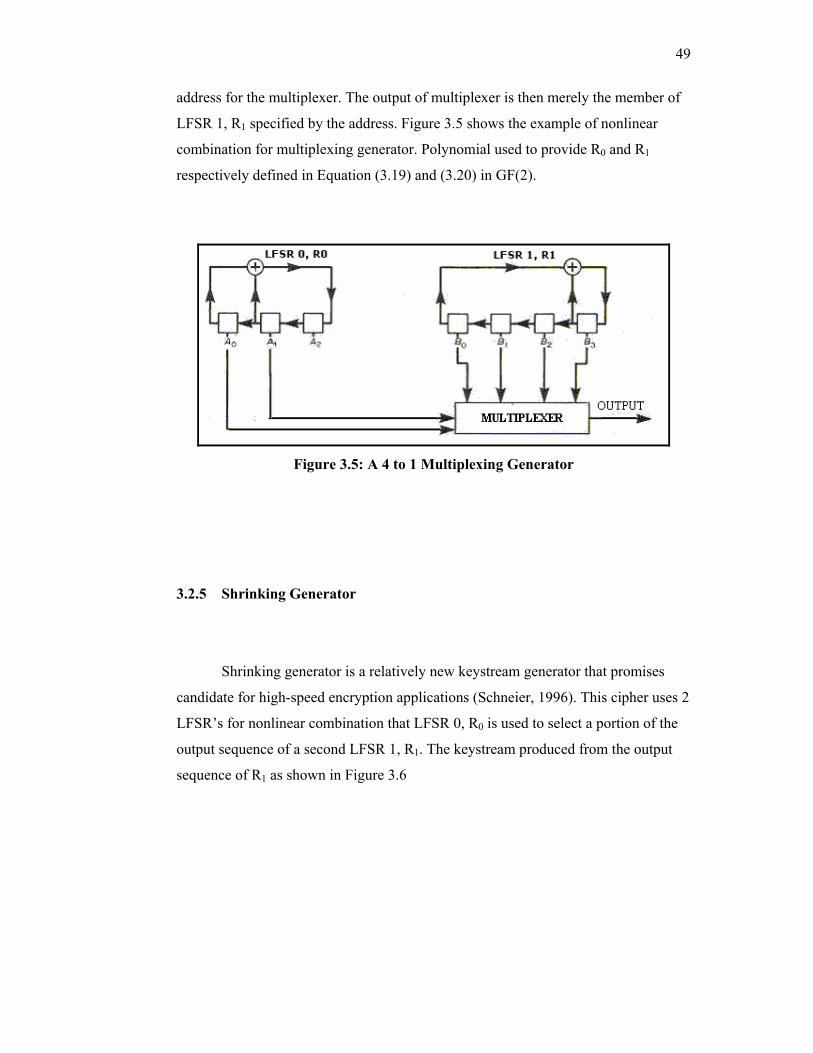
49
address for the multiplexer. The output of multiplexer is then merely the member of
LFSR 1, R1 specified by the address. Figure 3.5 shows the example of nonlinear
combination for multiplexing generator. Polynomial used to provide R0 and R1
respectively defined in Equation (3.19) and (3.20) in GF(2).
Figure 3.5: A 4 to 1 Multiplexing Generator
3.2.5 Shrinking Generator
Shrinking generator is a relatively new keystream generator that promises
candidate for high-speed encryption applications (Schneier, 1996). This cipher uses 2
LFSR’s for nonlinear combination that LFSR 0, R0 is used to select a portion of the
output sequence of a second LFSR 1, R1. The keystream produced from the output
sequence of R1 as shown in Figure 3.6
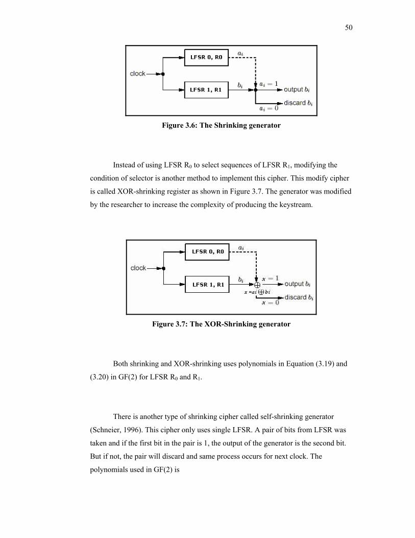
50
Figure 3.6: The Shrinking generator
Instead of using LFSR R0 to select sequences of LFSR R1, modifying the
condition of selector is another method to implement this cipher. This modify cipher
is called XOR-shrinking register as shown in Figure 3.7. The generator was modified
by the researcher to increase the complexity of producing the keystream.
Figure 3.7: The XOR-Shrinking generator
Both shrinking and XOR-shrinking uses polynomials in Equation (3.19) and
(3.20) in GF(2) for LFSR R0 and R1.
There is another type of shrinking cipher called self-shrinking generator
(Schneier, 1996). This cipher only uses single LFSR. A pair of bits from LFSR was
taken and if the first bit in the pair is 1, the output of the generator is the second bit.
But if not, the pair will discard and same process occurs for next clock. The
polynomials used in GF(2) is
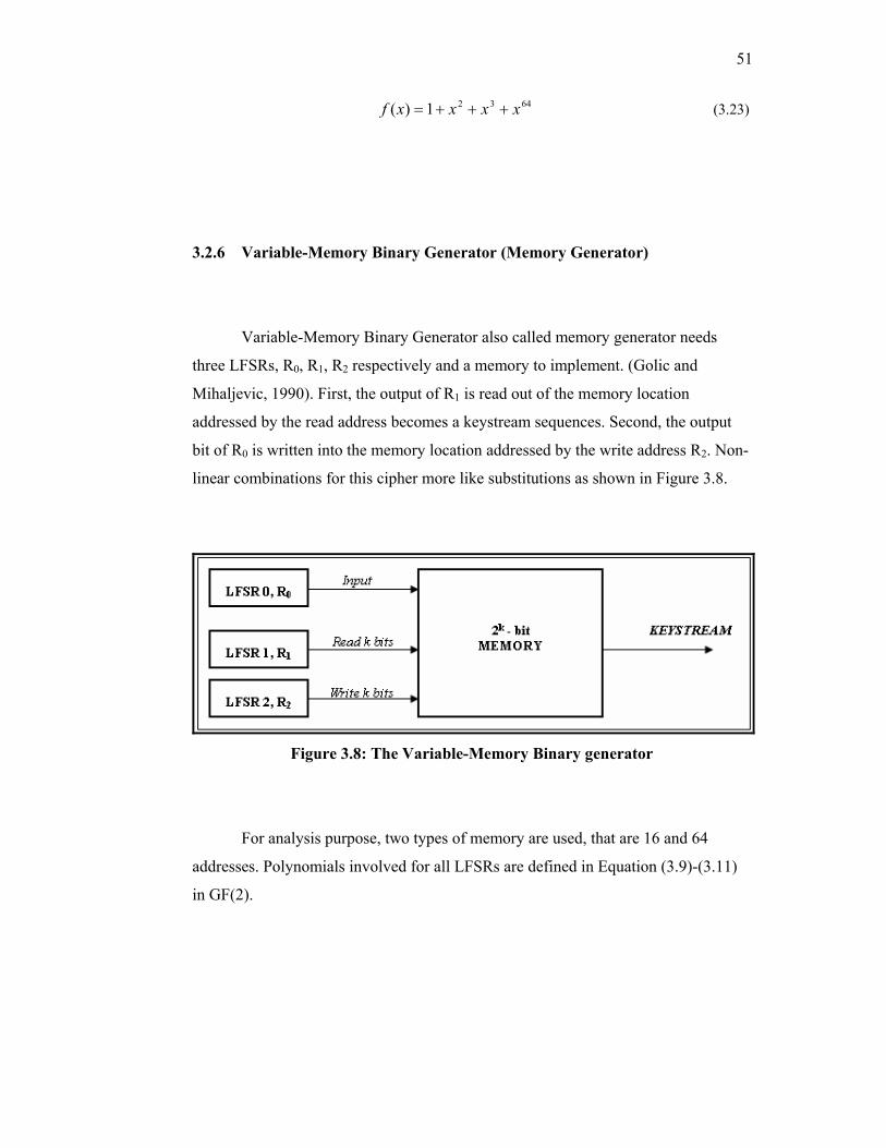
51
64321)( xxxxf +++= (3.23)
3.2.6 Variable-Memory Binary Generator (Memory Generator)
Variable-Memory Binary Generator also called memory generator needs
three LFSRs, R0, R1, R2 respectively and a memory to implement. (Golic and
Mihaljevic, 1990). First, the output of R1 is read out of the memory location
addressed by the read address becomes a keystream sequences. Second, the output
bit of R0 is written into the memory location addressed by the write address R2. Non-
linear combinations for this cipher more like substitutions as shown in Figure 3.8.
Figure 3.8: The Variable-Memory Binary generator
For analysis purpose, two types of memory are used, that are 16 and 64
addresses. Polynomials involved for all LFSRs are defined in Equation (3.9)-(3.11)
in GF(2).
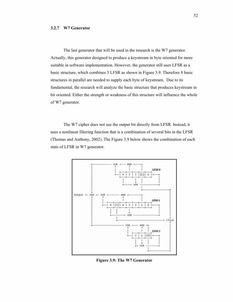
52
3.2.7 W7 Generator
The last generator that will be used in the research is the W7 generator.
Actually, this generator designed to produce a keystream in byte oriented for more
suitable in software implementation. However, the generator still uses LFSR as a
basic structure, which combines 3 LFSR as shown in Figure 3.9. Therefore 8 basic
structures in parallel are needed to supply each byte of keystream. Due to its
fundamental, the research will analyze the basic structure that produces keystream in
bit oriented. Either the strength or weakness of this structure will influence the whole
of W7 generator.
The W7 cipher does not use the output bit directly from LFSR. Instead, it
uses a nonlinear filtering function that is a combination of several bits in the LFSR
(Thomas and Anthony, 2002). The Figure 3.9 below shows the combination of each
state of LFSR in W7 generator.
Figure 3.9: The W7 Generator
53
The output of each correspond LFSR is the exclusive-OR of two quantities
which are the LFSR output and the output of logical-AND. For example, in Figure
3.7, the output of LFSR 0 is the result of exclusive-OR between bit 4 and logical
AND of bits 3 and 1. Finally, the random keystream produced from the exclusive OR
of the output of 3 LFSRs
)()()()( 210 nsnsnsnz ⊕⊕= (3.24)
where s0(n), s1(n) and s2(n) are the output of the LFSR 0 to 2. In addition, the 3
LFSRs together also determine when each shift register is clocked. One bit in each
register is designated as the clock tap for that register which represented by “[]” in
Figure 3.9. At each clock cycle, the majority value for those three taps determines
which LFSR actually advance. Only those LFSR whose clock taps agree with the
majority will advance. The LFSR’s used that is defined by polynomials as in
Equation (3.9)-(3.11) in GF(2).
3.3 Tests for Keystream Generator
There are several tests that can be used to quantify the strength of stream
ciphers. Standard tests that are independent of the algorithm are statistical tests,
correlation attack and linear complexity profile. Nonstandard test specific to the
algorithm based on the guess-and-determine attack is also used.
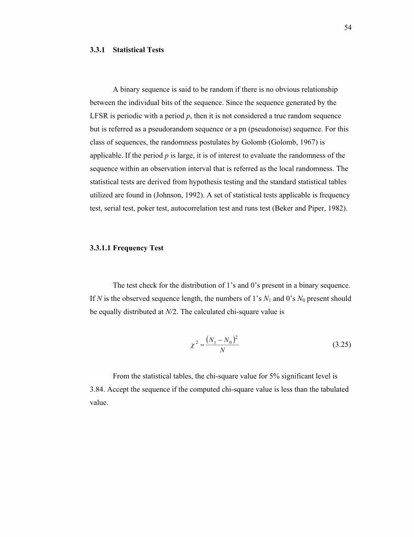
54
3.3.1 Statistical Tests
A binary sequence is said to be random if there is no obvious relationship
between the individual bits of the sequence. Since the sequence generated by the
LFSR is periodic with a period p, then it is not considered a true random sequence
but is referred as a pseudorandom sequence or a pn (pseudonoise) sequence. For this
class of sequences, the randomness postulates by Golomb (Golomb, 1967) is
applicable. If the period p is large, it is of interest to evaluate the randomness of the
sequence within an observation interval that is referred as the local randomness. The
statistical tests are derived from hypothesis testing and the standard statistical tables
utilized are found in (Johnson, 1992). A set of statistical tests applicable is frequency
test, serial test, poker test, autocorrelation test and runs test (Beker and Piper, 1982).
3.3.1.1 Frequency Test
The test check for the distribution of 1’s and 0’s present in a binary sequence.
If N is the observed sequence length, the numbers of 1’s N1 and 0’s N0 present should
be equally distributed at N/2. The calculated chi-square value is
( )N
NN 2012 −
=χ (3.25)
From the statistical tables, the chi-square value for 5% significant level is
3.84. Accept the sequence if the computed chi-square value is less than the tabulated
value.
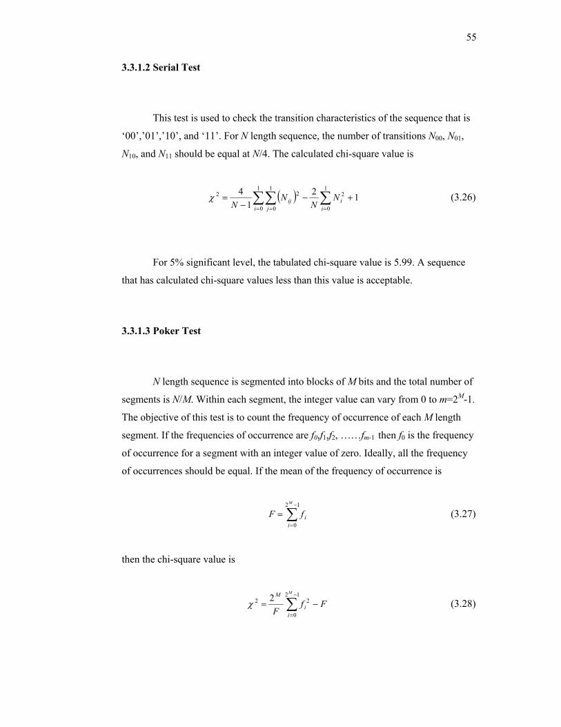
55
3.3.1.2 Serial Test
This test is used to check the transition characteristics of the sequence that is
‘00’,’01’,’10’, and ‘11’. For N length sequence, the number of transitions N00, N01,
N10, and N11 should be equal at N/4. The calculated chi-square value is
( ) 121
4 1
0
21
0
1
0
22 +−−
= ∑∑∑== = i
ii j
ij NN
NN
χ (3.26)
For 5% significant level, the tabulated chi-square value is 5.99. A sequence
that has calculated chi-square values less than this value is acceptable.
3.3.1.3 Poker Test
N length sequence is segmented into blocks of M bits and the total number of
segments is N/M. Within each segment, the integer value can vary from 0 to m=2M-1.
The objective of this test is to count the frequency of occurrence of each M length
segment. If the frequencies of occurrence are f0,f1,f2, ……fm-1 then f0 is the frequency
of occurrence for a segment with an integer value of zero. Ideally, all the frequency
of occurrences should be equal. If the mean of the frequency of occurrence is
∑−
=
=12
0
M
iifF (3.27)
then the chi-square value is
∑−
=
−=12
0
22 2M
ii
M
FfF
χ (3.28)
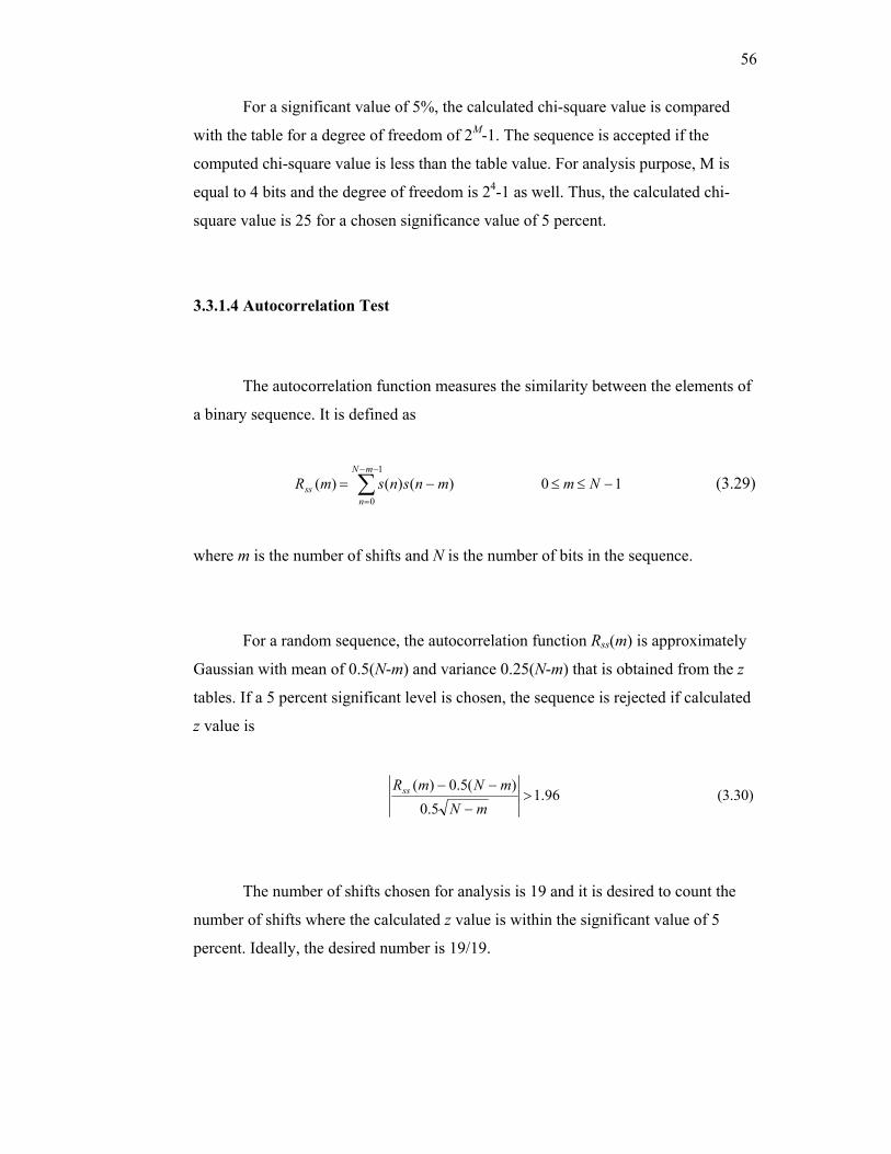
56
For a significant value of 5%, the calculated chi-square value is compared
with the table for a degree of freedom of 2M-1. The sequence is accepted if the
computed chi-square value is less than the table value. For analysis purpose, M is
equal to 4 bits and the degree of freedom is 24-1 as well. Thus, the calculated chi-
square value is 25 for a chosen significance value of 5 percent.
3.3.1.4 Autocorrelation Test
The autocorrelation function measures the similarity between the elements of
a binary sequence. It is defined as
∑−−
=
−=1
0
)()()(mN
nss mnsnsmR 10 −≤≤ Nm (3.29)
where m is the number of shifts and N is the number of bits in the sequence.
For a random sequence, the autocorrelation function Rss(m) is approximately
Gaussian with mean of 0.5(N-m) and variance 0.25(N-m) that is obtained from the z
tables. If a 5 percent significant level is chosen, the sequence is rejected if calculated
z value is
96.15.0
)(5.0)(>
−
−−
mNmNmRss (3.30)
The number of shifts chosen for analysis is 19 and it is desired to count the
number of shifts where the calculated z value is within the significant value of 5
percent. Ideally, the desired number is 19/19.
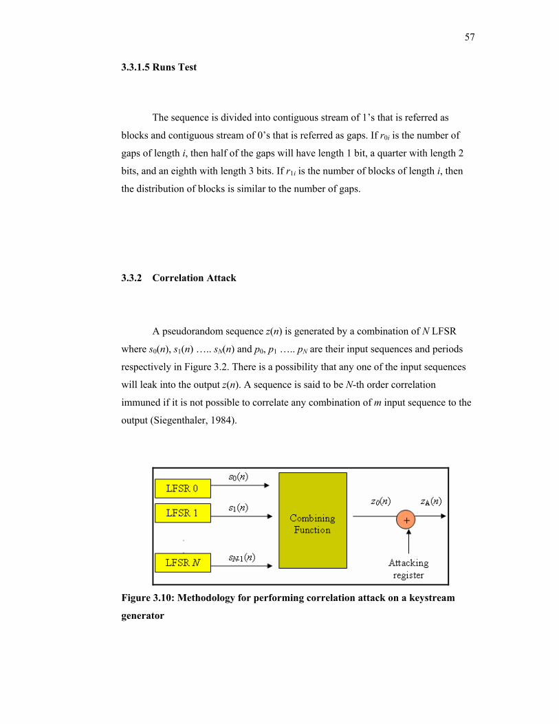
57
3.3.1.5 Runs Test
The sequence is divided into contiguous stream of 1’s that is referred as
blocks and contiguous stream of 0’s that is referred as gaps. If r0i is the number of
gaps of length i, then half of the gaps will have length 1 bit, a quarter with length 2
bits, and an eighth with length 3 bits. If r1i is the number of blocks of length i, then
the distribution of blocks is similar to the number of gaps.
3.3.2 Correlation Attack
A pseudorandom sequence z(n) is generated by a combination of N LFSR
where s0(n), s1(n) ….. sN(n) and p0, p1 ….. pN are their input sequences and periods
respectively in Figure 3.2. There is a possibility that any one of the input sequences
will leak into the output z(n). A sequence is said to be N-th order correlation
immuned if it is not possible to correlate any combination of m input sequence to the
output (Siegenthaler, 1984).
Figure 3.10: Methodology for performing correlation attack on a keystream
generator
58
For a pseudorandom sequence that is proven statistically random, it is desired
to find a sequence from an external register that is correlated to this sequence. The
following block diagram in Figure 3.10 explains how this is done. The setting of the
attacking register to anyone of the input register will result in the resulting sequence
z0(n) to be nonrandom. The randomness of zA(n) is quantified by performing a
statistical test such as frequency test on the sequence.
3.3.3 Linear Complexity Profile
If N length sequence is
s(n)=[ s(0) s(1) s(2) …….. s(N)] (3.31)
then the linear complexity of the sequence, denoted by L(N), is the length of the
shortest LFSR that will generate the first N terms of s(n). The properties of the linear
complexity for random sequence s(n) and r(n) are
(i) For any N ≥1, the linear complexity of a sequence s(n) satisfies
0≤L(N)≤N.
(ii) L(N)=0 if and only if s(n) a zero sequence of length N.
(iii) L(N)=N if and only if s(n)=[0,0,0,0 ….. 1].
(iv) If s(n) is periodic with period N, then L(N)≤N.
(v) If the linear complexity of s(n) and r(n) are L(N) and L(M)
respectively, the linear complexity of a sequence
z(n)=s(n)+r(n) (3.32)
Its relation to L(N) and L(M) is
L(P)≤L(N)+L(M) (3.33)
59
If s(n) sequence is defined as in sequence (3.31), then the linear complexity profile
LN of the sequence up to N is
L1,L2,…… LN (3.34)
Ideally, the linear complexity profile of a random sequence will increase
linearly with the n. If the linear complexity approaches a constant value L, the
resulting L-th length LFSR can be used to regenerate the random sequence. For this
analysis, Berlekamp-Massey algorithms used as Linear Complexity Profile test and
details of the algorithm can be found in (Massey, 1969). Analysis was done based on
10,000 bits sequences that provided by each keystream generator.
3.3.4 Guess and Determine (GD) Attack
Guess and Determine (GD) is a nonstandard and effective method in
analyzing stream ciphers. By considering the worst-case condition, this attack will
exploit the relationships between internal values (such as the recurrence relationship
in a shift register) and the relationship used to construct the keystream values from
the internal values (Hawkes and Rose, 2002). A GD attack guesses some internal
values and then exploits the relationships to determine other internal values. The
cipher is broken when a complete internal state has been determined from the
guessed values. However, this attack limits on generators that uses more than one
LFSR and their nonlinear functions is not complex where register value and
keystream that is produced correlates either forward or backward processes.
From the study, Self-shrinking is uses only one LFSR and for XOR-
Shrinking, W7 and both Memory Generators, their nonlinear combination are
complex. Therefore, these ciphers are immune on GD attacks. The following are the
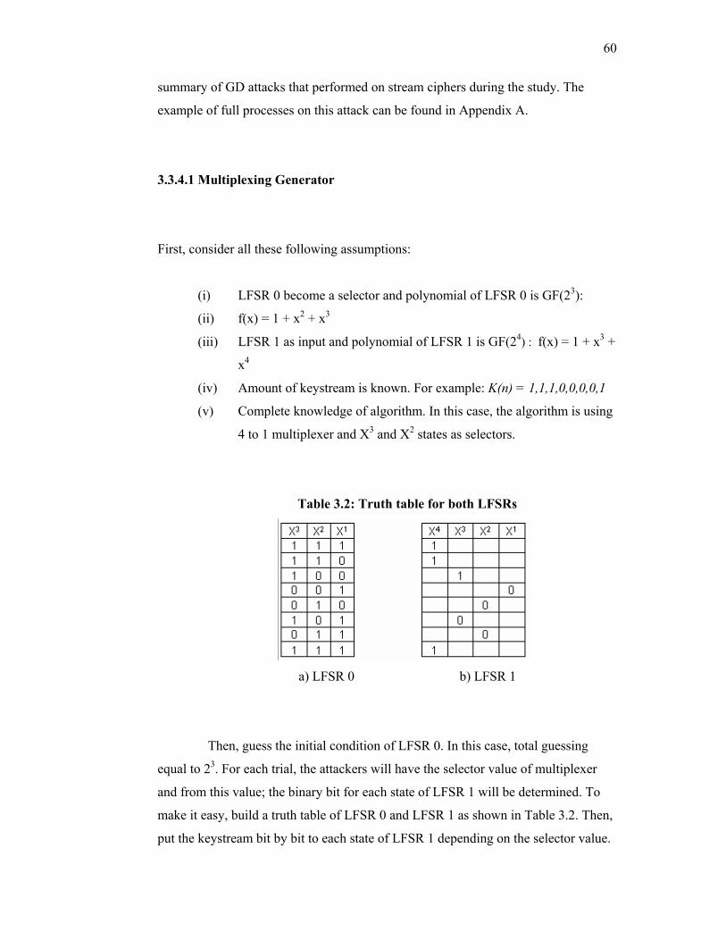
60
summary of GD attacks that performed on stream ciphers during the study. The
example of full processes on this attack can be found in Appendix A.
3.3.4.1 Multiplexing Generator
First, consider all these following assumptions:
(i) LFSR 0 become a selector and polynomial of LFSR 0 is GF(23):
(ii) f(x) = 1 + x2 + x3
(iii) LFSR 1 as input and polynomial of LFSR 1 is GF(24) : f(x) = 1 + x3 +
x4
(iv) Amount of keystream is known. For example: K(n) = 1,1,1,0,0,0,0,1
(v) Complete knowledge of algorithm. In this case, the algorithm is using
4 to 1 multiplexer and X3 and X2 states as selectors.
Table 3.2: Truth table for both LFSRs
a) LFSR 0 b) LFSR 1
Then, guess the initial condition of LFSR 0. In this case, total guessing
equal to 23. For each trial, the attackers will have the selector value of multiplexer
and from this value; the binary bit for each state of LFSR 1 will be determined. To
make it easy, build a truth table of LFSR 0 and LFSR 1 as shown in Table 3.2. Then,
put the keystream bit by bit to each state of LFSR 1 depending on the selector value.
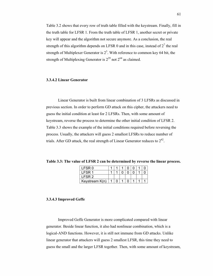
61
Table 3.2 shows that every row of truth table filled with the keystream. Finally, fill in
the truth table for LFSR 1. From the truth table of LFSR 1, another secret or private
key will appear and the algorithm not secure anymore. As a conclusion, the real
strength of this algorithm depends on LFSR 0 and in this case, instead of 27 the real
strength of Multiplexer Generator is 23. With reference to common key 64 bit, the
strength of Multiplexing Generator is 229 not 264 as claimed.
3.3.4.2 Linear Generator
Linear Generator is built from linear combination of 3 LFSRs as discussed in
previous section. In order to perform GD attack on this cipher, the attackers need to
guess the initial condition at least for 2 LFSRs. Then, with some amount of
keystream, reverse the process to determine the other initial condition of LFSR 2.
Table 3.3 shows the example of the initial conditions required before reversing the
process. Usually, the attackers will guess 2 smallest LFSRs to reduce number of
trials. After GD attack, the real strength of Linear Generator reduces to 242.
Table 3.3: The value of LFSR 2 can be determined by reverse the linear process.
LFSR 0 1 1 1 0 0 1 0LFSR 1 1 1 0 0 0 1 0LFSR 2 Keystream K(n) 1 0 1 0 1 1 1
3.3.4.3 Improved Geffe
Improved Geffe Generator is more complicated compared with linear
generator. Beside linear function, it also had nonlinear combination, which is a
logical-AND functions. However, it is still not immune from GD attacks. Unlike
linear generator that attackers will guess 2 smallest LFSR, this time they need to
guess the small and the larger LFSR together. Then, with some amount of keystream,
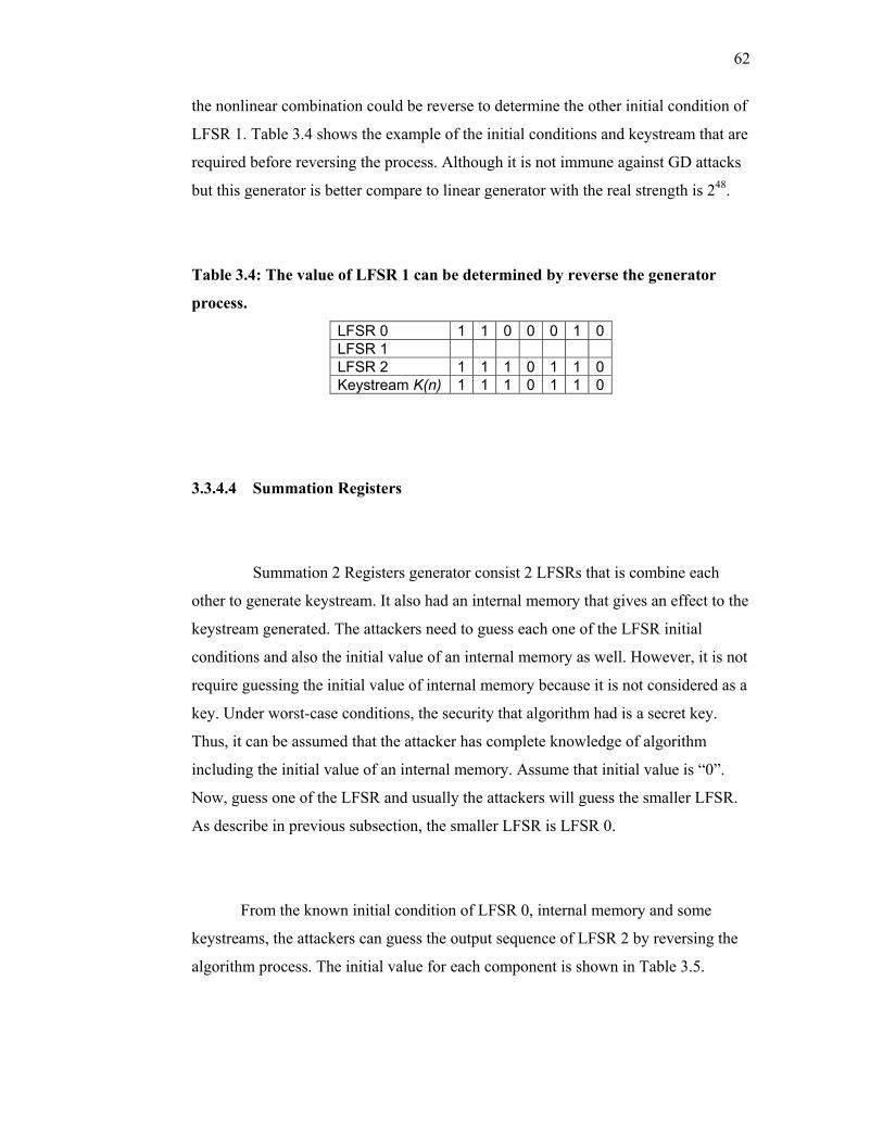
62
the nonlinear combination could be reverse to determine the other initial condition of
LFSR 1. Table 3.4 shows the example of the initial conditions and keystream that are
required before reversing the process. Although it is not immune against GD attacks
but this generator is better compare to linear generator with the real strength is 248.
Table 3.4: The value of LFSR 1 can be determined by reverse the generator
process.
LFSR 0 1 1 0 0 0 1 0LFSR 1 LFSR 2 1 1 1 0 1 1 0Keystream K(n) 1 1 1 0 1 1 0
3.3.4.4 Summation Registers
Summation 2 Registers generator consist 2 LFSRs that is combine each
other to generate keystream. It also had an internal memory that gives an effect to the
keystream generated. The attackers need to guess each one of the LFSR initial
conditions and also the initial value of an internal memory as well. However, it is not
require guessing the initial value of internal memory because it is not considered as a
key. Under worst-case conditions, the security that algorithm had is a secret key.
Thus, it can be assumed that the attacker has complete knowledge of algorithm
including the initial value of an internal memory. Assume that initial value is “0”.
Now, guess one of the LFSR and usually the attackers will guess the smaller LFSR.
As describe in previous subsection, the smaller LFSR is LFSR 0.
From the known initial condition of LFSR 0, internal memory and some
keystreams, the attackers can guess the output sequence of LFSR 2 by reversing the
algorithm process. The initial value for each component is shown in Table 3.5.
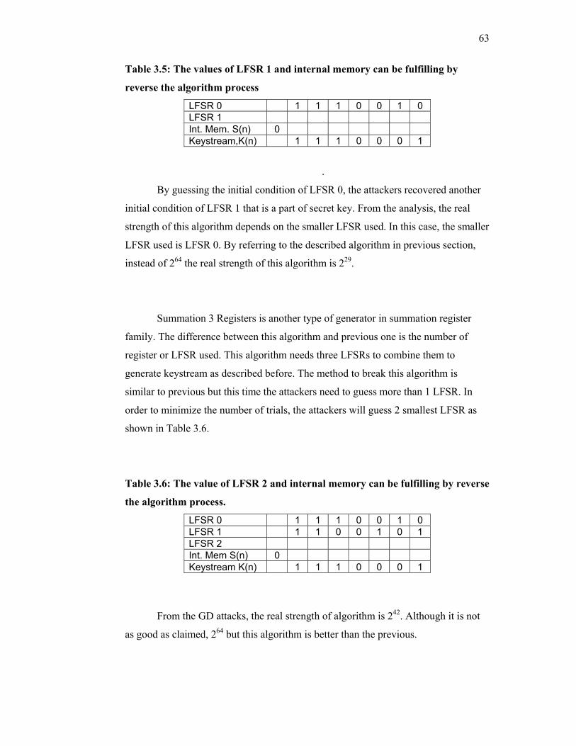
63
Table 3.5: The values of LFSR 1 and internal memory can be fulfilling by
reverse the algorithm process
LFSR 0 1 1 1 0 0 1 0 LFSR 1 Int. Mem. S(n) 0 Keystream,K(n) 1 1 1 0 0 0 1
.
By guessing the initial condition of LFSR 0, the attackers recovered another
initial condition of LFSR 1 that is a part of secret key. From the analysis, the real
strength of this algorithm depends on the smaller LFSR used. In this case, the smaller
LFSR used is LFSR 0. By referring to the described algorithm in previous section,
instead of 264 the real strength of this algorithm is 229.
Summation 3 Registers is another type of generator in summation register
family. The difference between this algorithm and previous one is the number of
register or LFSR used. This algorithm needs three LFSRs to combine them to
generate keystream as described before. The method to break this algorithm is
similar to previous but this time the attackers need to guess more than 1 LFSR. In
order to minimize the number of trials, the attackers will guess 2 smallest LFSR as
shown in Table 3.6.
Table 3.6: The value of LFSR 2 and internal memory can be fulfilling by reverse
the algorithm process.
LFSR 0 1 1 1 0 0 1 0 LFSR 1 1 1 0 0 1 0 1 LFSR 2 Int. Mem S(n) 0 Keystream K(n) 1 1 1 0 0 0 1
From the GD attacks, the real strength of algorithm is 242. Although it is not
as good as claimed, 264 but this algorithm is better than the previous.
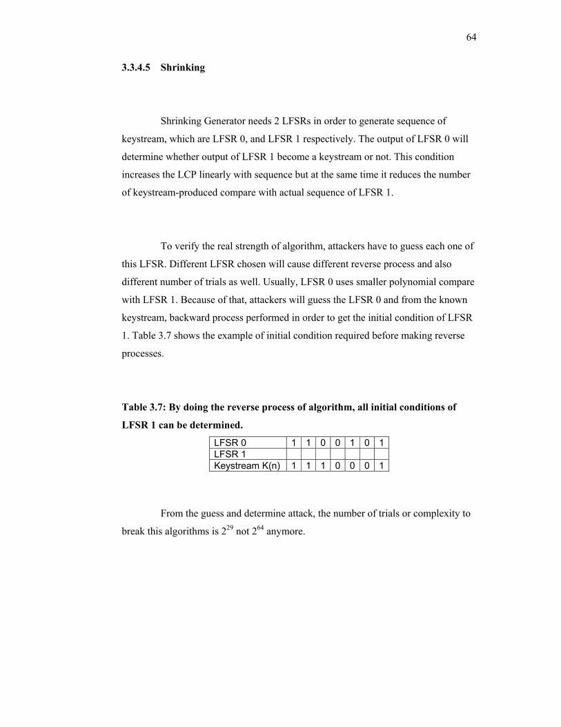
64
3.3.4.5 Shrinking
Shrinking Generator needs 2 LFSRs in order to generate sequence of
keystream, which are LFSR 0, and LFSR 1 respectively. The output of LFSR 0 will
determine whether output of LFSR 1 become a keystream or not. This condition
increases the LCP linearly with sequence but at the same time it reduces the number
of keystream-produced compare with actual sequence of LFSR 1.
To verify the real strength of algorithm, attackers have to guess each one of
this LFSR. Different LFSR chosen will cause different reverse process and also
different number of trials as well. Usually, LFSR 0 uses smaller polynomial compare
with LFSR 1. Because of that, attackers will guess the LFSR 0 and from the known
keystream, backward process performed in order to get the initial condition of LFSR
1. Table 3.7 shows the example of initial condition required before making reverse
processes.
Table 3.7: By doing the reverse process of algorithm, all initial conditions of
LFSR 1 can be determined.
LFSR 0 1 1 0 0 1 0 1LFSR 1 Keystream K(n) 1 1 1 0 0 0 1
From the guess and determine attack, the number of trials or complexity to
break this algorithms is 229 not 264 anymore.
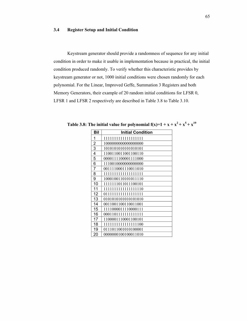
65
3.4 Register Setup and Initial Condition
Keystream generator should provide a randomness of sequence for any initial
condition in order to make it usable in implementation because in practical, the initial
condition produced randomly. To verify whether this characteristic provides by
keystream generator or not, 1000 initial conditions were chosen randomly for each
polynomial. For the Linear, Improved Geffe, Summation 3 Registers and both
Memory Generators, their example of 20 random initial conditions for LFSR 0,
LFSR 1 and LFSR 2 respectively are described in Table 3.8 to Table 3.10.
Table 3.8: The initial value for polynomial f(x)=1 + x + x2 + x5 + x19
Bil Initial Condition 1 1111111111111111111 2 1000000000000000000 3 1010101010101010101 4 1100110011001100110 5 0000111100001111000 6 1110010000000000000 7 0011110001110011010 8 1111111111111111111 9 1000100110101011110 10 1111111011011100101 11 1111111111111111110 12 0111111111111111111 13 0101010101010101010 14 0011001100110011001 15 1111000011110000111 16 0001101111111111111 17 1100001110001100101 18 1111111111111111100 19 0111011001010100001 20 0000000100100011010
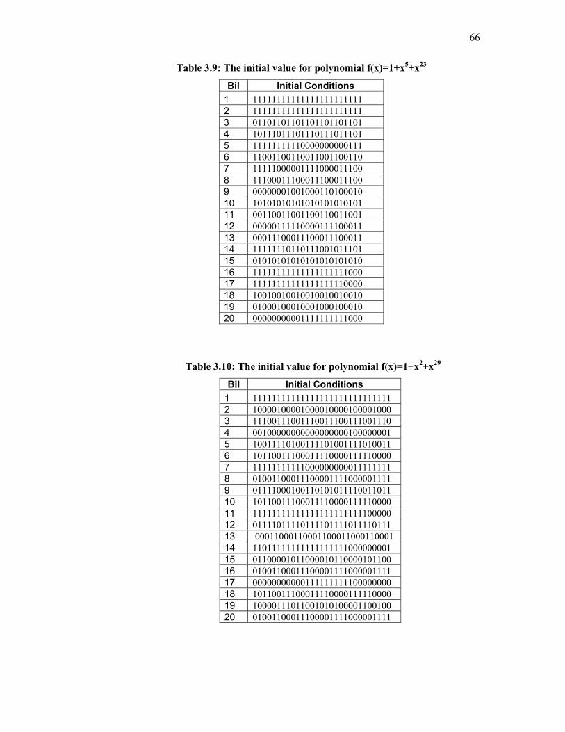
66
Table 3.9: The initial value for polynomial f(x)=1+x5+x23
Bil Initial Conditions 1 11111111111111111111111 2 11111111111111111111111 3 01101101101101101101101 4 10111011101110111011101 5 11111111110000000000111 6 11001100110011001100110 7 11111000001111000011100 8 11100011100011100011100 9 00000001001000110100010 10 10101010101010101010101 11 00110011001100110011001 12 00000111110000111100011 13 00011100011100011100011 14 11111110110111001011101 15 01010101010101010101010 16 11111111111111111111000 17 11111111111111111110000 18 10010010010010010010010 19 01000100010001000100010 20 00000000001111111111000
Table 3.10: The initial value for polynomial f(x)=1+x2+x29
Bil Initial Conditions 1 11111111111111111111111111111 2 10000100001000010000100001000 3 11100111001110011100111001110 4 00100000000000000000100000001 5 10011110100111101001111010011 6 10110011100011110000111110000 7 11111111111000000000011111111 8 01001100011100001111000001111 9 01111000100110101011110011011 10 10110011100011110000111110000 11 11111111111111111111111100000 12 01111011110111101111011110111 13 00011000110001100011000110001 14 11011111111111111111000000001 15 01100001011000010110000101100 16 01001100011100001111000001111 17 00000000000111111111100000000 18 10110011100011110000111110000 19 10000111011001010100001100100 20 01001100011100001111000001111

67
The example random initial conditions for both LFSR that is used for the
Summation 2 Registers, Multiplexing, Shrinking and XOR-Shrinking generator are
shown in Table 3.11 and Table 3.12. And finally, for Self-shrinking generator, its
random initial conditions are described in Table 3.13.
Table 3.11: The initial value for polynomial f(x) = 1 + x2 + x29
Bil Initial Conditions 1 11111111111111111111111111111 2 10101010101010101010101010101 3 10011001100110011001100110011 4 11100100000001010011100101110 5 00100011010001010110011110001 6 11100011100011100011100011100 7 00000000000000000000000000001 8 10000000000000000000011101100 9 11110000111100001111000011110 10 10110011100011110000111100001 11 11111111111111111111111000000 12 01010101010101010101010101010 13 01100110011001100110011001100 14 00011011111110101100011010001 15 11011100101110101001100001110 16 00011100011100011100011100011 17 11111111111111111111111111110 18 01111111111111111111100010011 19 00001111000011110000111100001 20 01001100011100001111000011110
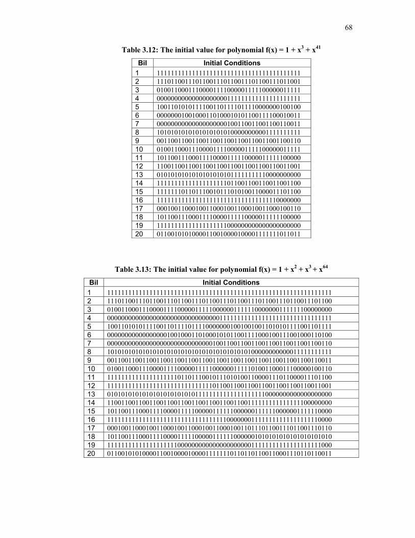
68
Table 3.12: The initial value for polynomial f(x) = 1 + x3 + x41
Bil Initial Conditions 1 11111111111111111111111111111111111111111 2 11101100111011001110110011101100111011001 3 01001100011100001111000001111100000011111 4 00000000000000000000111111111111111111111 5 10011010101111001101111011110000000100100 6 00000001001000110100010101100111100010011 7 00000000000000000000100110011001100110011 8 10101010101010101010100000000001111111111 9 00110011001100110011001100110011001100110 10 01001100011100001111000001111100000011111 11 10110011100011110000111110000011111100000 12 11001100110011001100110011001100110011001 13 01010101010101010101011111111110000000000 14 11111111111111111111011001100110011001100 15 11111110110111001011101010011000011101100 16 11111111111111111111111111111111110000000 17 00010011000100110001001100010011000100110 18 10110011100011110000111110000011111100000 19 11111111111111111111000000000000000000000 20 01100101010000110010000100001111111011011
Table 3.13: The initial value for polynomial f(x) = 1 + x2 + x3 + x64
Bil Initial Conditions 1 1111111111111111111111111111111111111111111111111111111111111111 2 1110110011101100111011001110110011101100111011001110110011101100 3 0100110001110000111100000111110000001111110000000111111100000000 4 0000000000000000000000000000000011111111111111111111111111111111 5 1001101010111100110111101111000000010010010011010101111001101111 6 0000000000000000010010001101000101011001111000100111001000110100 7 0000000000000000000000000000001001100110011001100110011001100110 8 1010101010101010101010101010101010101010100000000000011111111111 9 0011001100110011001100110011001100110011001100110011001100110011 10 0100110001110000111100000111110000001111101001100011100000100110 11 1111111111111111111101101110010111010100110000111011000011101100 12 1111111111111111111111111111110110011001100110011001100110011001 13 0101010101010101010101010111111111111111111110000000000000000000 14 1100110011001100110011001100110011001100111111111111111100000000 15 1011001110001111000011111000001111110000001111110000001111110000 16 1111111111111111111111111111111111000000011111111111111111110000 17 0001001100010011000100110001001100010011011101100111011001110110 18 1011001110001111000011111000001111110000001010101010101010101010 19 1111111111111111111100000000000000000000011111111111111111111000 20 0110010101000011001000010000111111101101101100110001110110110011
69
For all keystream generators, the simulation program was written in C++
language and by using small LFSR, the program is checked step-by-step process to
verify the output at every stage in the algorithm. The verification of the generator can
be found in Appendix A. Then, the keystream for each generator was analyzed to
determine their statistical properties, correlation immunity and complexity.
The statistical test programs were checked by testing a number of large
sequences that are well known to have good statistical properties confirming that
they will pass the entire test. For correlation attack, the program was checked by
XOR a sequence N length of LFSR with the output of external register using the
same initial state and coefficient. The result from the frequency test should be equal
to N. Finally for linear complexity profile, the program was checked by finding the
linear complexity of a number of sequences from known linear feedback shift
register.
The entire simulation program must working properly to ensure the results
obtained from the analysis are accurate in order to determine the good stream cipher
system.
3.5 Analysis Results
The analyses were performed using standard test such as statistical tests,
correlation attack and linear complexity profile and also nonstandard test that is the
guess-and-determine attack. The following are the results for each test that were
made.
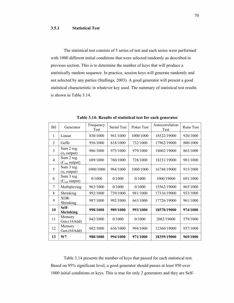
70
3.5.1 Statistical Test
The statistical test consists of 5 series of test and each series were performed
with 1000 different initial conditions that were selected randomly as described in
previous section. This is to determine the number of keys that will produce a
statistically random sequence. In practice, session keys will generate randomly and
not selected by any parties (Stallings, 2003). A good generator will present a good
statistical characteristic in whatever key used. The summary of statistical test results
is shown in Table 3.14.
Table 3.14: Results of statistical test for each generator
Bil Generator Frequency Test Serial Test Poker Test Autocorrelation
Test Runs Test
1 Linear 830/1000 941/1000 1000/1000 18522/19000 920/1000
2 Geffe 956/1000 818/1000 732/1000 17962/19000 800/1000
3 Sum 2 reg. (z0 output) 986/1000 975/1000 979/1000 18002/19000 863/1000
4 Sum 2 reg. (Cout output) 689/1000 760/1000 728/1000 18231/19000 981/1000
5 Sum 3 reg. (z0 output) 1000/1000 984/1000 1000/1000 16748/19000 915/1000
6 Sum 3 reg (Cout output) 0/1000 0/1000 0/1000 1000/19000 691/1000
7 Multiplexing 963/1000 0/1000 0/1000 15562/19000 865/1000 8 Shrinking 992/1000 739/1000 981/1000 17316/19000 933/1000
9 XOR-Shrinking 987/1000 992/1000 663/1000 17726/19000 961/1000
10 Self-Shrinking 998/1000 989/1000 993/1000 18578/19000 974/1000
11 Memory Gen.(16Add) 842/1000 0/1000 0/1000 2082/19000 579/1000
12 Memory Gen.(64Add) 882/1000 636/1000 994/1000 12360/19000 937/1000
13 W7 988/1000 994/1000 971/1000 18359/19000 969/1000
Table 3.14 presents the number of keys that passed for each statistical test.
Based on 95% significant level, a good generator should passes at least 950 over
1000 initial conditions or keys. This is true for only 2 generators and they are Self-
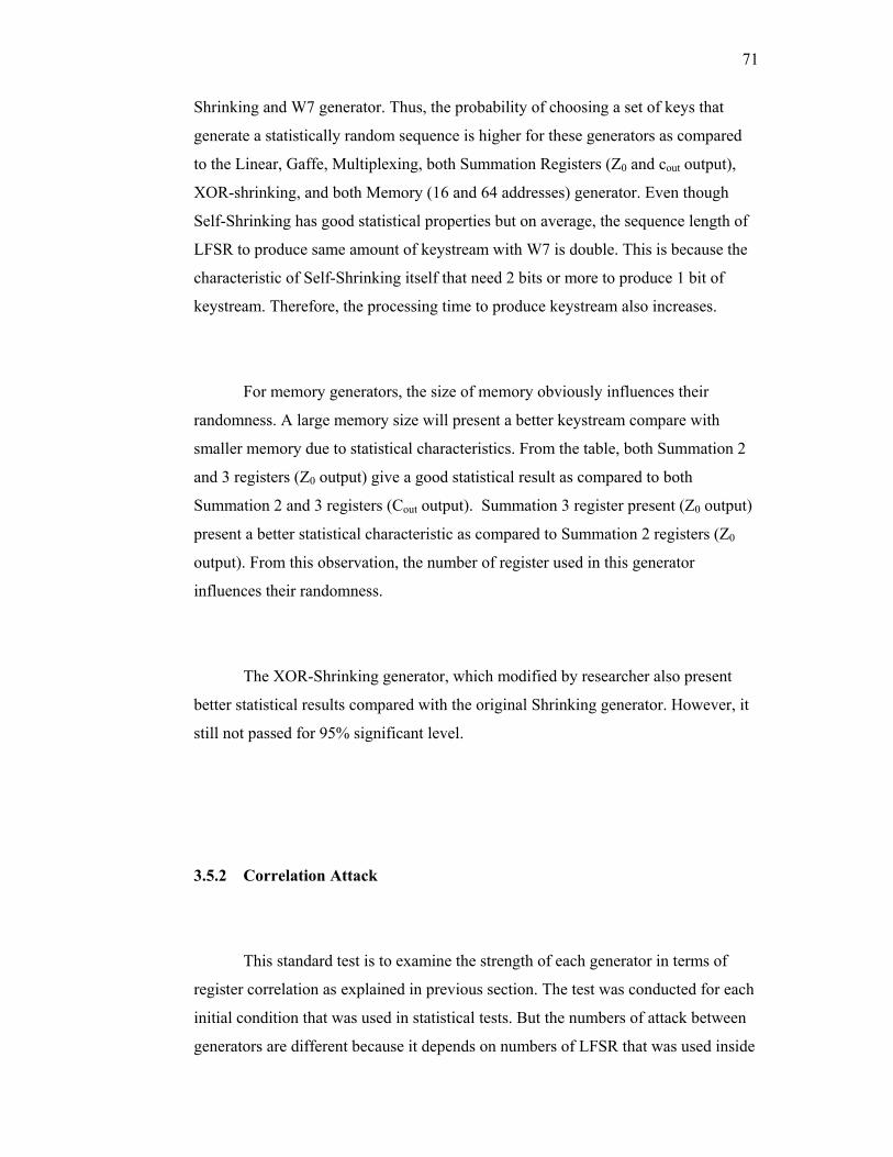
71
Shrinking and W7 generator. Thus, the probability of choosing a set of keys that
generate a statistically random sequence is higher for these generators as compared
to the Linear, Gaffe, Multiplexing, both Summation Registers (Z0 and cout output),
XOR-shrinking, and both Memory (16 and 64 addresses) generator. Even though
Self-Shrinking has good statistical properties but on average, the sequence length of
LFSR to produce same amount of keystream with W7 is double. This is because the
characteristic of Self-Shrinking itself that need 2 bits or more to produce 1 bit of
keystream. Therefore, the processing time to produce keystream also increases.
For memory generators, the size of memory obviously influences their
randomness. A large memory size will present a better keystream compare with
smaller memory due to statistical characteristics. From the table, both Summation 2
and 3 registers (Z0 output) give a good statistical result as compared to both
Summation 2 and 3 registers (Cout output). Summation 3 register present (Z0 output)
present a better statistical characteristic as compared to Summation 2 registers (Z0
output). From this observation, the number of register used in this generator
influences their randomness.
The XOR-Shrinking generator, which modified by researcher also present
better statistical results compared with the original Shrinking generator. However, it
still not passed for 95% significant level.
3.5.2 Correlation Attack
This standard test is to examine the strength of each generator in terms of
register correlation as explained in previous section. The test was conducted for each
initial condition that was used in statistical tests. But the numbers of attack between
generators are different because it depends on numbers of LFSR that was used inside

72
the generator. The frequency test is performed to check the output of correlation
attacks in order to verify the sequence of LFSR used into combining function leaks
into keystream or not. The summary of correlation attacks is shown in Table 3.15.
The strength of generators is presented as correlation immunity, which is the
numbers of attacks that passes the frequency test.
Table 3.15: Result for Correlation Attacks
Bil Keystream Generator Correlation Immunity 1 Linear generator 56 out of 60 were immune 2 Improved Geffe 0 out of 60 were immune 3 Summation 2 registers (z0 output) 25 out of 40 were immune 4 Summation 2 registers (Cout output) 3 out of 40 were immune 5 Summation 3 registers (z0 output) 54 out of 60 were immune 6 Summation 3 registers (Cout output) 5 out of 60 were immune 7 Multiplexing 19 out of 40 were immune 8 Shrinking 38 out of 40 were immune 9 XOR-Shrinking 38 out of 40 were immune 10 Self-Shrinking 19 out of 20 were immune 11 Memory Generator (16 Addresses) 33 out of 60 were immune 12 Memory Generator (64 Addresses) 50 out of 60 were immune 13 W7 Generator 58 out of 60 were immune
From observation, Linear generator, Summations 3 Registers (Z0 output),
Shrinking, XOR-shrinking, Self-shrinking, Memory generators (64 addresses) and
W7 generator present good performance where 80% of attacks were immune. For
Multiplexing, Memory Registers (16 addresses) and Summation 2 Registers (Z0
output), half of the possible attacks were successful. Others generators were
absolutely not immune and can be easily broken by this attack. Notice that the
strength of generator will reduce to 2N trials with, N as the length of LFSR that leaks
into keystream. With reference to Table 3.14, both self-shrinking and W7 generator
that pass the statistical test are immune on correlation attack as shown in Table 3.15.
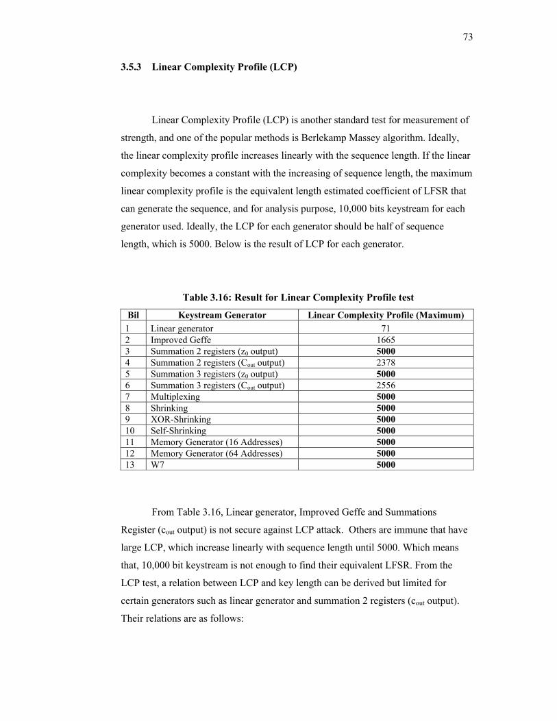
73
3.5.3 Linear Complexity Profile (LCP)
Linear Complexity Profile (LCP) is another standard test for measurement of
strength, and one of the popular methods is Berlekamp Massey algorithm. Ideally,
the linear complexity profile increases linearly with the sequence length. If the linear
complexity becomes a constant with the increasing of sequence length, the maximum
linear complexity profile is the equivalent length estimated coefficient of LFSR that
can generate the sequence, and for analysis purpose, 10,000 bits keystream for each
generator used. Ideally, the LCP for each generator should be half of sequence
length, which is 5000. Below is the result of LCP for each generator.
Table 3.16: Result for Linear Complexity Profile test
Bil Keystream Generator Linear Complexity Profile (Maximum) 1 Linear generator 71 2 Improved Geffe 1665 3 Summation 2 registers (z0 output) 5000 4 Summation 2 registers (Cout output) 2378 5 Summation 3 registers (z0 output) 5000 6 Summation 3 registers (Cout output) 2556 7 Multiplexing 5000 8 Shrinking 5000 9 XOR-Shrinking 5000 10 Self-Shrinking 5000 11 Memory Generator (16 Addresses) 5000 12 Memory Generator (64 Addresses) 5000 13 W7 5000
From Table 3.16, Linear generator, Improved Geffe and Summations
Register (cout output) is not secure against LCP attack. Others are immune that have
large LCP, which increase linearly with sequence length until 5000. Which means
that, 10,000 bit keystream is not enough to find their equivalent LFSR. From the
LCP test, a relation between LCP and key length can be derived but limited for
certain generators such as linear generator and summation 2 registers (cout output).
Their relations are as follows:
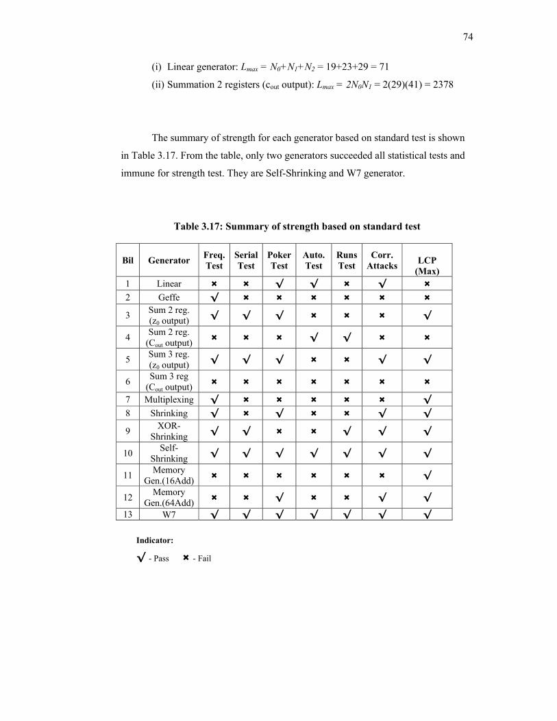
74
(i) Linear generator: Lmax = N0+N1+N2 = 19+23+29 = 71
(ii) Summation 2 registers (cout output): Lmax = 2N0N1 = 2(29)(41) = 2378
The summary of strength for each generator based on standard test is shown
in Table 3.17. From the table, only two generators succeeded all statistical tests and
immune for strength test. They are Self-Shrinking and W7 generator.
Table 3.17: Summary of strength based on standard test
Indicator:
√ - Pass × - Fail
Bil Generator Freq.Test
Serial Test
Poker Test
Auto. Test
Runs Test
Corr. Attacks
LCP
(Max) 1 Linear × × √ √ × √ × 2 Geffe √ × × × × × ×
3 Sum 2 reg. (z0 output) √ √ √ × × × √
4 Sum 2 reg. (Cout output) × × × √ √ × ×
5 Sum 3 reg. (z0 output) √ √ √ × × √ √
6 Sum 3 reg (Cout output) × × × × × × ×
7 Multiplexing √ × × × × × √ 8 Shrinking √ × √ × × √ √
9 XOR-Shrinking √ √ × × √ √ √
10 Self-Shrinking √ √ √ √ √ √ √
11 Memory Gen.(16Add) × × × × × × √
12 Memory Gen.(64Add) × × √ × × √ √
13 W7 √ √ √ √ √ √ √
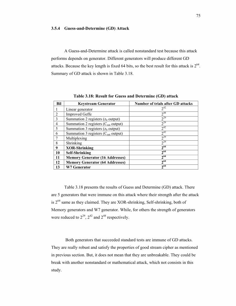
75
3.5.4 Guess-and-Determine (GD) Attack
A Guess-and-Determine attack is called nonstandard test because this attack
performs depends on generator. Different generators will produce different GD
attacks. Because the key length is fixed 64 bits, so the best result for this attack is 264.
Summary of GD attack is shown in Table 3.18.
Table 3.18: Result for Guess and Determine (GD) attack
Bil Keystream Generator Number of trials after GD attacks 1 Linear generator 242 2 Improved Geffe 248 3 Summation 2 registers (z0 output) 229 4 Summation 2 registers (Cout output) 229 5 Summation 3 registers (z0 output) 242 6 Summation 3 registers (Cout output) 242 7 Multiplexing 229 8 Shrinking 229 9 XOR-Shrinking 264 10 Self-Shrinking 264 11 Memory Generator (16 Addresses) 264 12 Memory Generator (64 Addresses) 264 13 W7 Generator 264
Table 3.18 presents the results of Guess and Determine (GD) attack. There
are 5 generators that were immune on this attack where their strength after the attack
is 264 same as they claimed. They are XOR-shrinking, Self-shrinking, both of
Memory generators and W7 generator. While, for others the strength of generators
were reduced to 229, 242 and 248 respectively.
Both generators that succeeded standard tests are immune of GD attacks.
They are really robust and satisfy the properties of good stream cipher as mentioned
in previous section. But, it does not mean that they are unbreakable. They could be
break with another nonstandard or mathematical attack, which not consists in this
study.
76
3.5.5 Discussion
After the analyses of 13 keystream generators, there are 2 cipher systems that
pass all tests. They are Self-Shrinking andW7 stream ciphers. Due to the
performance of computer technology at present in term of speed and memory space,
both cipher system can be implemented easily on Secured HF Transmission System
but only W7 generator is adopted. Based on the performance, this cipher system will
guarantee the digital information that exchange through radio communication, which
is confidential. For other cipher systems, analysis shows that they have some strength
and weaknesses. However, it does not mean that they are useless because they are
still applicable for implementation depending on application and information to
protect.
Basically, the encryption purpose correlates with cover time. Cover time is
defined as the length of time the encryption algorithm can protect plaintext when
subjected to an attack (Nichols, 2002). The cover time should also consider the
expected security value of the information and the existing computer technology that
is presently available. Usually, longer cover time requires stronger encryption
algorithm.
The time, T to crack the algorithms is
T = 2L/R (3.35)
where L is the key length and R is the processing rate expressed as key per second
(Nichols, 2002). With current computer processing which is capable to process 100
million keys per second, the 128 bit key length is preferred because it would take
1020 years to search all possible keys. Due to Secured HF Transmission System, if
the information is top secret, then the key should be increase to 128 bits key.
Expanding the polynomial of W7 cipher system can do this but the structure of
algorithm is still the same.
77
3.5 Conclusion
The stream cipher is a type of cipher system where the process of enciphering
and deciphering is performed one bit at a type. This type of cipher is useful in noisy
channel conditions such as in radio communication environment and bulk data
transmission. Comparisons in performance are made for several stream ciphers based
on the statistical test, correlation attack, linear complexity profile and guess-
determine attacks. From analyses, a cipher system which succeeds all the tests is
chosen to adopt in Secured HF Image Transmission System. It is the W7 cipher
system.
CHAPTER 4
IMPLEMENTATION OF DQPSK HF MODEM
In digital communication, modulation and demodulation are important aspect
to make communication possible. They are compromise with the type of channel
propagation. As mention in Chapter 2, HF propagation is unpredictable and varying
by time. Therefore the suitable method or technique for both modulation and
demodulation are needed to increase the reliability and throughput during data
transmission.
4.1 Differential Quadrature Phase Shift Keying (DQPSK) Theory
DQPSK is a derivation of Differential Phase Shift Keying (DPSK) where the
two main characteristics of DQPSK and DPSK are the same; information is encoded
in the phase transition and previous signal is used as the reference signal. The
advantage of DQPSK is that it is more spectrums efficient, which make its
transmission rate to be double compared to DPSK. DQPSK data transfer rate is twice
the transfer rates of DPSK. In DQPSK, a symbol represents 2 bits of data, and this is
achieved by encoding the data in the constellation as illustrated in Figure 4.1. The
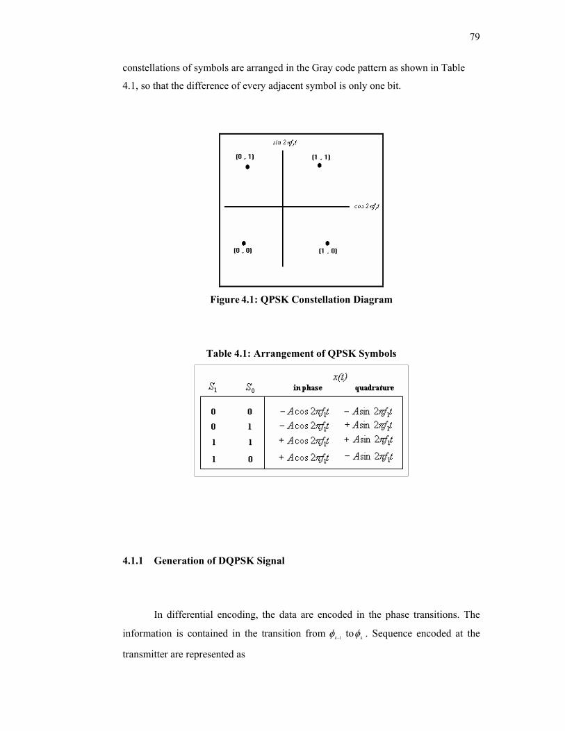
79
constellations of symbols are arranged in the Gray code pattern as shown in Table
4.1, so that the difference of every adjacent symbol is only one bit.
Figure 4.1: QPSK Constellation Diagram
Table 4.1: Arrangement of QPSK Symbols
4.1.1 Generation of DQPSK Signal
In differential encoding, the data are encoded in the phase transitions. The
information is contained in the transition from 1−kφ to kφ . Sequence encoded at the
transmitter are represented as
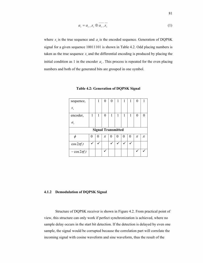
81
kkkkk sasaa .. 11 −− ⊕= (1)
where ks is the true sequence and ka is the encoded sequence. Generation of DQPSK
signal for a given sequence 10011101 is shown in Table 4.2. Odd placing numbers is
taken as the true sequence ks and the differential encoding is produced by placing the
initial condition as 1 in the encoder ka . This process is repeated for the even placing
numbers and both of the generated bits are grouped in one symbol.
Table 4.2: Generation of DQPSK Signal
4.1.2 Demodulation of DQPSK Signal
Structure of DQPSK receiver is shown in Figure 4.2. From practical point of
view, this structure can only work if perfect synchronization is achieved, where no
sample delay occurs in the start bit detection. If the detection is delayed by even one
sample, the signal would be corrupted because the correlation part will correlate the
incoming signal with cosine waveform and sine waveform, thus the result of the
sequence,
ks
1 0 0 1 1 1 0 1
encoder,
ka
1 1 0 1 1 1 1 0 0
Signal Transmitted
φ 0 0 π 0 0 0 0 π π
tf12cos π
tf12cos π−
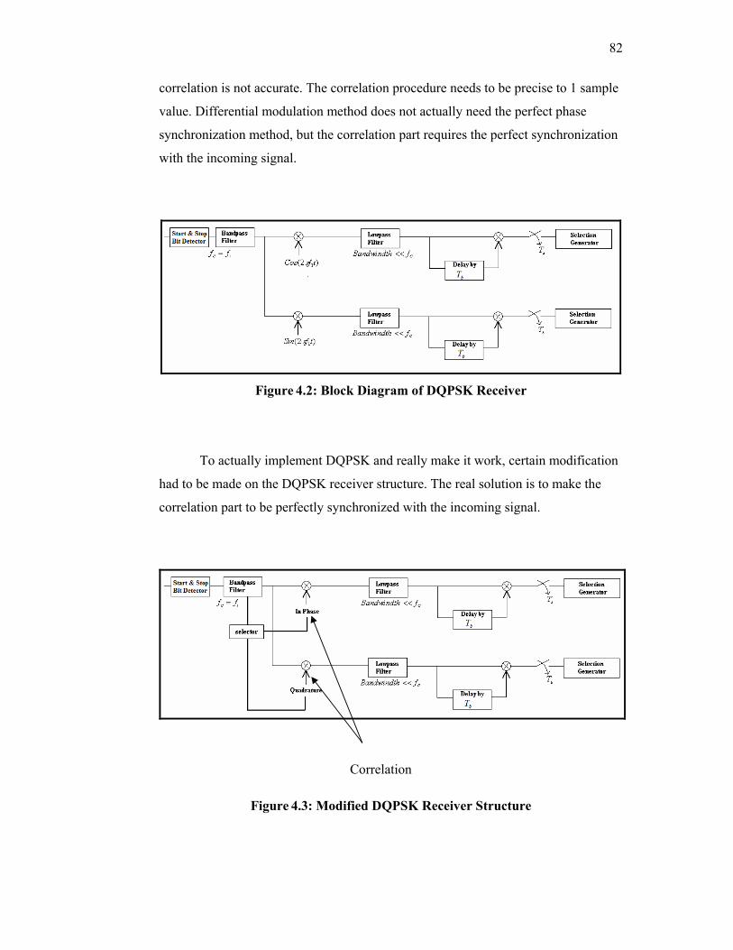
82
correlation is not accurate. The correlation procedure needs to be precise to 1 sample
value. Differential modulation method does not actually need the perfect phase
synchronization method, but the correlation part requires the perfect synchronization
with the incoming signal.
Figure 4.2: Block Diagram of DQPSK Receiver
To actually implement DQPSK and really make it work, certain modification
had to be made on the DQPSK receiver structure. The real solution is to make the
correlation part to be perfectly synchronized with the incoming signal.
Figure 4.3: Modified DQPSK Receiver Structure
Correlation
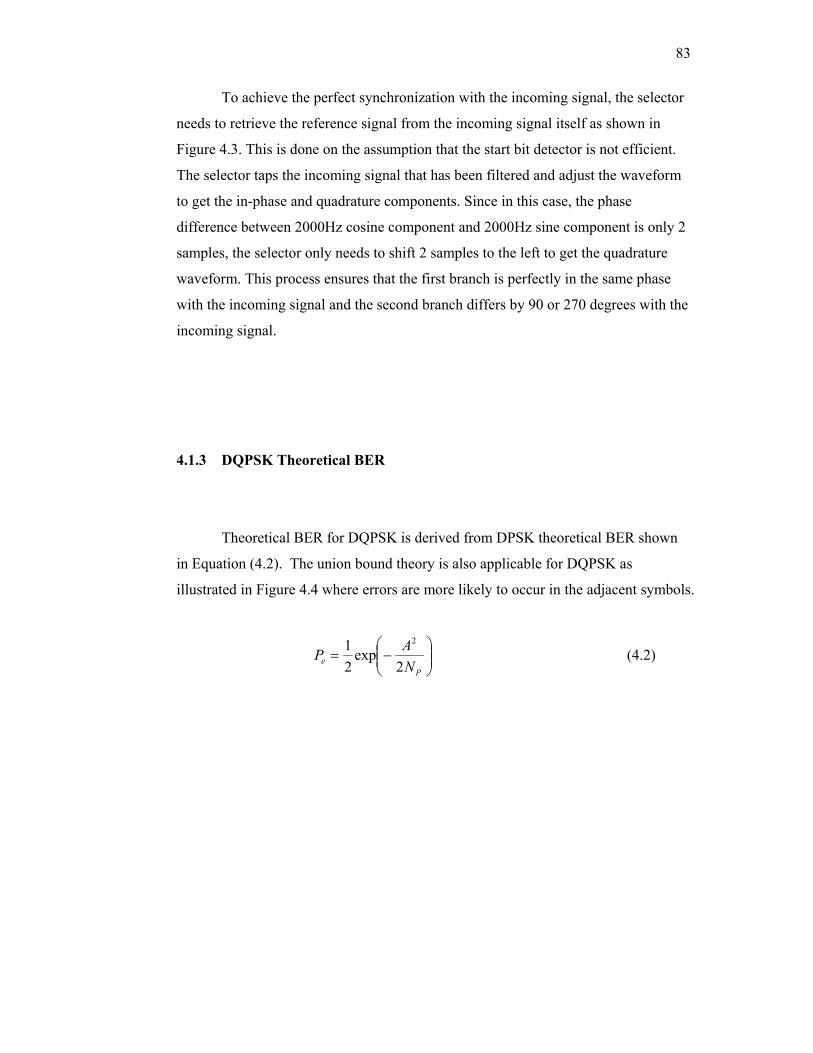
83
To achieve the perfect synchronization with the incoming signal, the selector
needs to retrieve the reference signal from the incoming signal itself as shown in
Figure 4.3. This is done on the assumption that the start bit detector is not efficient.
The selector taps the incoming signal that has been filtered and adjust the waveform
to get the in-phase and quadrature components. Since in this case, the phase
difference between 2000Hz cosine component and 2000Hz sine component is only 2
samples, the selector only needs to shift 2 samples to the left to get the quadrature
waveform. This process ensures that the first branch is perfectly in the same phase
with the incoming signal and the second branch differs by 90 or 270 degrees with the
incoming signal.
4.1.3 DQPSK Theoretical BER
Theoretical BER for DQPSK is derived from DPSK theoretical BER shown
in Equation (4.2). The union bound theory is also applicable for DQPSK as
illustrated in Figure 4.4 where errors are more likely to occur in the adjacent symbols.
−=
Pe N
AP2
exp21 2
(4.2)
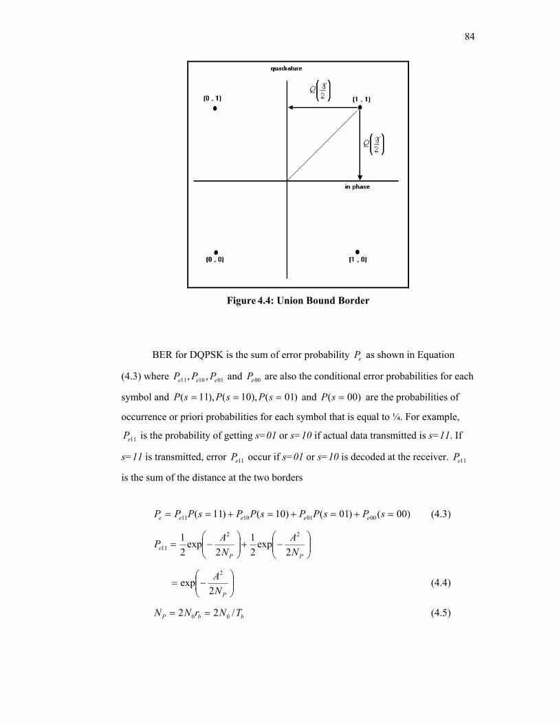
84
Figure 4.4: Union Bound Border
BER for DQPSK is the sum of error probability eP as shown in Equation
(4.3) where 011011 ,, eee PPP and 00eP are also the conditional error probabilities for each
symbol and )01(),10(),11( === sPsPsP and )00( =sP are the probabilities of
occurrence or priori probabilities for each symbol that is equal to ¼. For example,
11eP is the probability of getting s=01 or s=10 if actual data transmitted is s=11. If
s=11 is transmitted, error 11eP occur if s=01 or s=10 is decoded at the receiver. 11eP
is the sum of the distance at the two borders
)00()01()10()11( 00011011 =+=+=+== sPsPPsPPsPPP eeeee (4.3)
−+
−=
PPe N
ANAP
2exp
21
2exp
21 22
11
−=
PNA
2exp
2
(4.4)
bbP TNrNN /22 00 == (4.5)
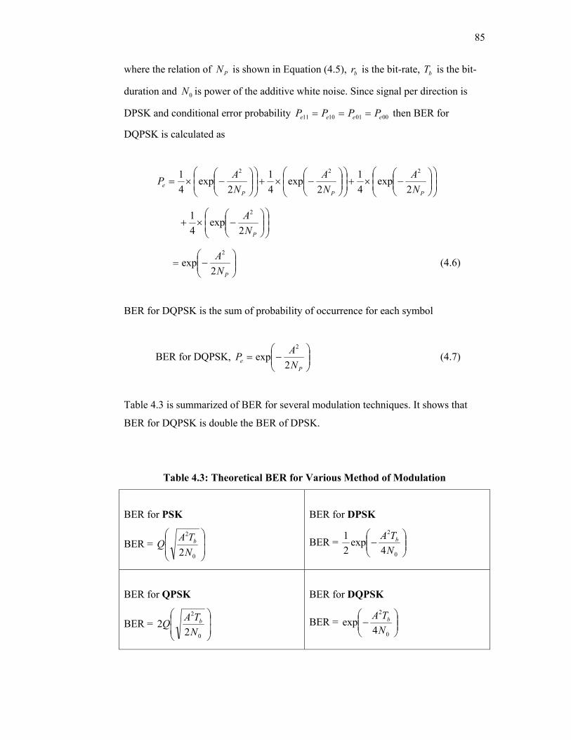
85
where the relation of PN is shown in Equation (4.5), br is the bit-rate, bT is the bit-
duration and 0N is power of the additive white noise. Since signal per direction is
DPSK and conditional error probability 00011011 eeee PPPP === then BER for
DQPSK is calculated as
−×+
−×+
−×=
PPPe N
ANA
NAP
2exp
41
2exp
41
2exp
41 222
−×+
PNA
2exp
41 2
−=
PNA
2exp
2
(4.6)
BER for DQPSK is the sum of probability of occurrence for each symbol
BER for DQPSK,
−=
Pe N
AP2
exp2
(4.7)
Table 4.3 is summarized of BER for several modulation techniques. It shows that
BER for DQPSK is double the BER of DPSK.
Table 4.3: Theoretical BER for Various Method of Modulation
BER for PSK
BER =
0
2
2NTAQ b
BER for DPSK
BER =
−
0
2
4exp
21
NTA b
BER for QPSK
BER =
0
2
22
NTAQ b
BER for DQPSK
BER =
−
0
2
4exp
NTA b
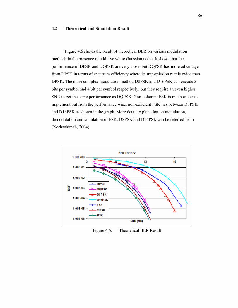
86
4.2 Theoretical and Simulation Result
Figure 4.6 shows the result of theoretical BER on various modulation
methods in the presence of additive white Gaussian noise. It shows that the
performance of DPSK and DQPSK are very close, but DQPSK has more advantage
from DPSK in terms of spectrum efficiency where its transmission rate is twice than
DPSK. The more complex modulation method D8PSK and D16PSK can encode 3
bits per symbol and 4 bit per symbol respectively, but they require an even higher
SNR to get the same performance as DQPSK. Non-coherent FSK is much easier to
implement but from the performance wise, non-coherent FSK lies between D8PSK
and D16PSK as shown in the graph. More detail explanation on modulation,
demodulation and simulation of FSK, D8PSK and D16PSK can be referred from
(Norhashimah, 2004).
Figure 4.6: Theoretical BER Result
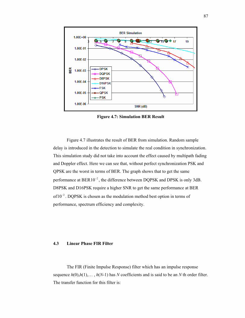
87
Figure 4.7: Simulation BER Result
Figure 4.7 illustrates the result of BER from simulation. Random sample
delay is introduced in the detection to simulate the real condition in synchronization.
This simulation study did not take into account the effect caused by multipath fading
and Doppler effect. Here we can see that, without perfect synchronization PSK and
QPSK are the worst in terms of BER. The graph shows that to get the same
performance at BER 210− , the difference between DQPSK and DPSK is only 3dB.
D8PSK and D16PSK require a higher SNR to get the same performance at BER
of 210− . DQPSK is chosen as the modulation method best option in terms of
performance, spectrum efficiency and complexity.
4.3 Linear Phase FIR Filter
The FIR (Finite Impulse Response) filter which has an impulse response
sequence h(0),h(1),… , h(N-1) has N coefficients and is said to be an N th order filter.
The transfer function for this filter is:
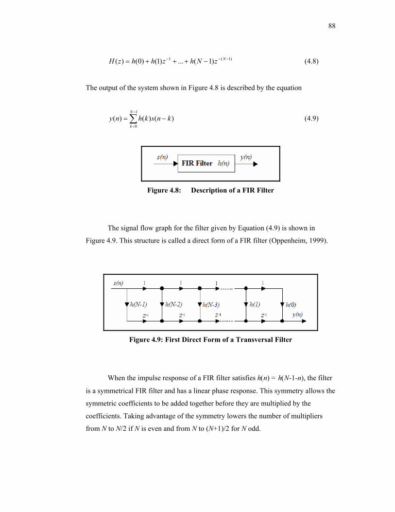
88
)1(1 )1(...)1()0()( −−− −+++= NzNhzhhzH (4.8)
The output of the system shown in Figure 4.8 is described by the equation
∑−
=
−=1
0)()()(
N
kknskhny (4.9)
Figure 4.8: Description of a FIR Filter
The signal flow graph for the filter given by Equation (4.9) is shown in
Figure 4.9. This structure is called a direct form of a FIR filter (Oppenheim, 1999).
Figure 4.9: First Direct Form of a Transversal Filter
When the impulse response of a FIR filter satisfies h(n) = h(N-1-n), the filter
is a symmetrical FIR filter and has a linear phase response. This symmetry allows the
symmetric coefficients to be added together before they are multiplied by the
coefficients. Taking advantage of the symmetry lowers the number of multipliers
from N to N/2 if N is even and from N to (N+1)/2 for N odd.
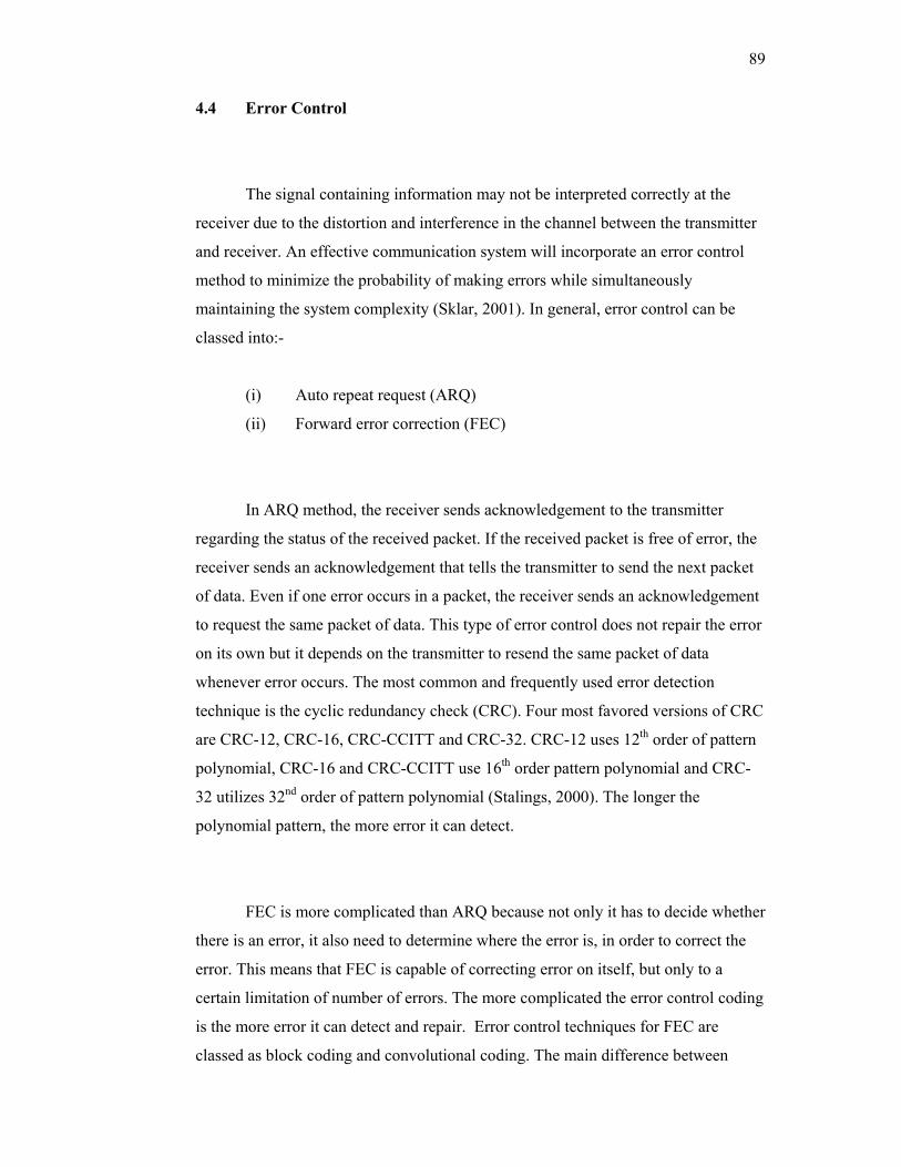
89
4.4 Error Control
The signal containing information may not be interpreted correctly at the
receiver due to the distortion and interference in the channel between the transmitter
and receiver. An effective communication system will incorporate an error control
method to minimize the probability of making errors while simultaneously
maintaining the system complexity (Sklar, 2001). In general, error control can be
classed into:-
(i) Auto repeat request (ARQ)
(ii) Forward error correction (FEC)
In ARQ method, the receiver sends acknowledgement to the transmitter
regarding the status of the received packet. If the received packet is free of error, the
receiver sends an acknowledgement that tells the transmitter to send the next packet
of data. Even if one error occurs in a packet, the receiver sends an acknowledgement
to request the same packet of data. This type of error control does not repair the error
on its own but it depends on the transmitter to resend the same packet of data
whenever error occurs. The most common and frequently used error detection
technique is the cyclic redundancy check (CRC). Four most favored versions of CRC
are CRC-12, CRC-16, CRC-CCITT and CRC-32. CRC-12 uses 12th order of pattern
polynomial, CRC-16 and CRC-CCITT use 16th order pattern polynomial and CRC-
32 utilizes 32nd order of pattern polynomial (Stalings, 2000). The longer the
polynomial pattern, the more error it can detect.
FEC is more complicated than ARQ because not only it has to decide whether
there is an error, it also need to determine where the error is, in order to correct the
error. This means that FEC is capable of correcting error on itself, but only to a
certain limitation of number of errors. The more complicated the error control coding
is the more error it can detect and repair. Error control techniques for FEC are
classed as block coding and convolutional coding. The main difference between
90
block coding and convolutional coding is that the calculation process for block
coding is done in the fixed length of data in a block whereas for convolutional coding,
the calculation is done bit by bit. Some of the well-known block codes are Hamming
codes, BCH codes, Reed-Solomon codes and Golay codes. Golay code is chosen to
handle the error correction part for this system. Golay code is a ½ code rate and it is
capable in correcting all triple errors or less. Hamming codes can only correct one
error. BCH codes and Reed-Solomon codes are not ½ code rate coding but they can
correct triple error.
Both ARQ and FEC are implemented using binary cyclic code method which
is explained in detail in section 4.4.1.
4.4.1 Binary Cyclic Code
Binary cyclic codes are an important subclass of linear block codes. The
codes are easily implemented with feedback shift registers and the syndrome
calculation is easily accomplished using similar feedback shift registers. The cyclic
nature of the code can be expressed in polynomial form. In order to clearly
understand the process, the method should be viewed as a long division in the Galois
field (GF (2)) or polynomial form. If we have a binary sequence
m= [ ]1 1 1 1 1 0 0 0 0 0 1 1 , the polynomial representation in the GF (2) is
m(x) = 12341011 ++++++ xxxxxx (4.10)
The polynomial is shifted 12 bits to the left to calculate the checksum for
extended Golay code application. Left shift operation is denoted as multiplication
with 12x as shown below:
91
)()(' 12 xmxxm = (4.11)
Referring to Equation (4.10), the 12 bits left shift operation produces
Equation (4.12) where the power of every polynomial increases.
12131415162223)(' xxxxxxxxm ++++++= (4.12)
Various types of error control method exist and each utilizes a completely
different pattern polynomial. This example is based on the implementation of
extended Golay code. The polynomial in Equation (4.12) is then divided with a
p= ]001111101010[ pattern sequence that has a polynomial representation
p(x) = 1567911 ++++++ xxxxxx (4.13)
The remainder r(x) or checksum is calculated by dividing the sequence m’(x)
with its pattern polynomial p(x) as shown in the following equation
)()()(' xu
xpxm
= with remainder r(x)
)(mod)(')( xpxmxr = (4.14)
where u(x) is the result of the long division. Actual long division operation is
illustrated in Figure 4.10.
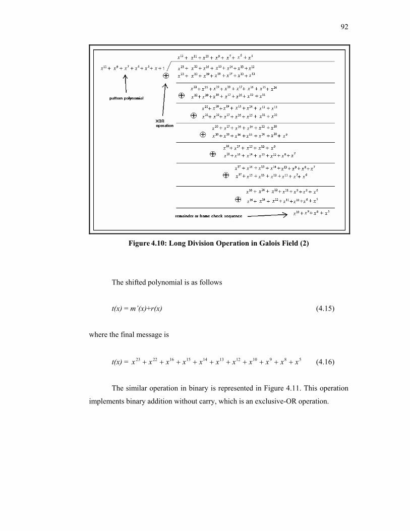
92
Figure 4.10: Long Division Operation in Galois Field (2)
The shifted polynomial is as follows
t(x) = m’(x)+r(x) (4.15)
where the final message is
t(x) = 5891012131415162223 xxxxxxxxxxx ++++++++++ (4.16)
The similar operation in binary is represented in Figure 4.11. This operation
implements binary addition without carry, which is an exclusive-OR operation.
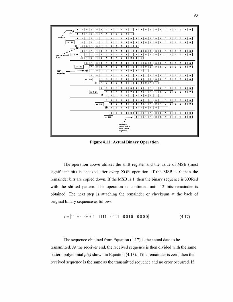
93
Figure 4.11: Actual Binary Operation
The operation above utilizes the shift register and the value of MSB (most
significant bit) is checked after every XOR operation. If the MSB is 0 than the
remainder bits are copied down. If the MSB is 1, then the binary sequence is XORed
with the shifted pattern. The operation is continued until 12 bits remainder is
obtained. The next step is attaching the remainder or checksum at the back of
original binary sequence as follows
[ ]0 0 0 0 0 1 0 0 1 1 1 0 1 1 1 1 1 0 0 0 0 0 1 1=t (4.17)
The sequence obtained from Equation (4.17) is the actual data to be
transmitted. At the receiver end, the received sequence is then divided with the same
pattern polynomial p(x) shown in Equation (4.13). If the remainder is zero, then the
received sequence is the same as the transmitted sequence and no error occurred. If
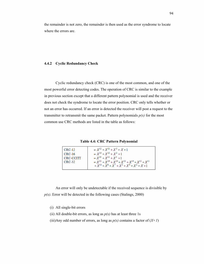
94
the remainder is not zero, the remainder is then used as the error syndrome to locate
where the errors are.
4.4.2 Cyclic Redundancy Check
Cyclic redundancy check (CRC) is one of the most common, and one of the
most powerful error detecting codes. The operation of CRC is similar to the example
in previous section except that a different pattern polynomial is used and the receiver
does not check the syndrome to locate the error position. CRC only tells whether or
not an error has occurred. If an error is detected the receiver will post a request to the
transmitter to retransmit the same packet. Pattern polynomials p(x) for the most
common use CRC methods are listed in the table as follows:
Table 4.4: CRC Pattern Polynomial
An error will only be undetectable if the received sequence is divisible by
p(x). Error will be detected in the following cases (Stalings, 2000)
(i) All single-bit errors
(ii) All double-bit errors, as long as p(x) has at least three 1s
(iii)Any odd number of errors, as long as p(x) contains a factor of (X+1)
95
(iv) Any burst error for which the length of the burst is less than the length of the
pattern polynomial; that is, less than or equal to the length of the frame check
sequence or check sum
4.4.3 Extended Golay Code
One of the more useful block codes is the binary (24, 12) extended Golay
code, which is formed by adding an overall bit to the perfect (23, 12) code, known as
the Golay code (Sklar, 2001). This added bit increases the minimum distance mind
from 7 to 8 and produces a rate 1/2 code, which is easier to implement than the 12/23
original Golay code. Minimum distance for the extended Golay code, mind = 8, where
the code is guaranteed to correct all triple errors.
Total error pattern possibilities for 12 bits of data plus 12 bits of checksum
are 2046. A look-up table is implemented since the size of memory needs to be
allocated for the look-up table is quite small. Error syndrome for Golay code is
stored in external memory on board DSK board starting from address 0xF000 until
0xFFFF.
A snippet of error correcting code is inserted in Figure 4.12 to show how the
error correction is performed at the receiver. Before proceeding to the error control
part, the received bit is divided to 6 groups of 24 bits of data. Each group of 24 bits is
then decoded to calculate the syndrome. Error occurs in the packet if the syndrome is
not equal to zero. As shown in the code in Figure 4.12, error correction is only
executed if error occurred in the packet. Error pattern is located by referring to the
error syndrome, where the error syndrome acts as a binary pointer to point to the
exact location inside the memory.
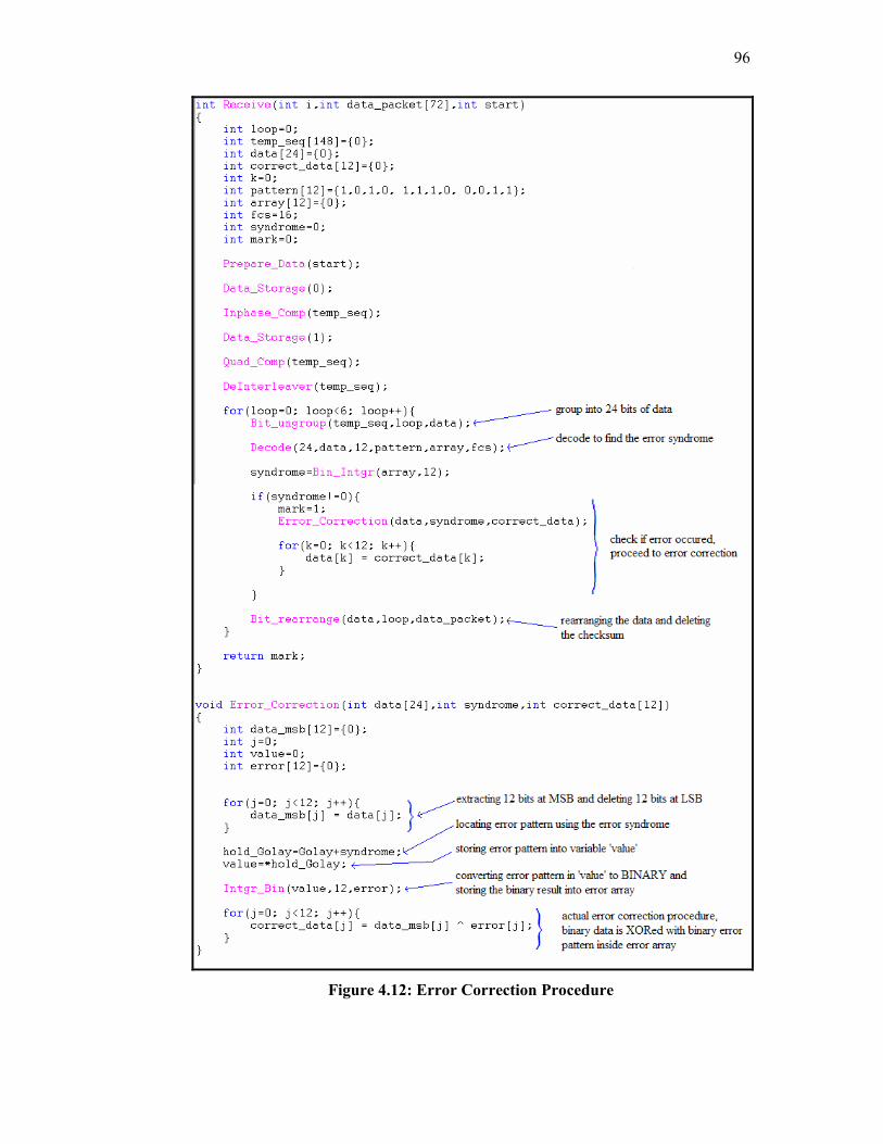
96
Figure 4.12: Error Correction Procedure
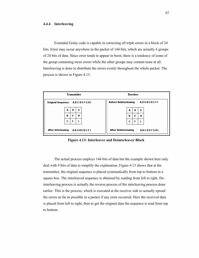
97
4.4.4 Interleaving
Extended Golay code is capable in correcting all triple errors in a block of 24
bits. Error may occur anywhere in the packet of 144 bits, which are actually 6 groups
of 24 bits of data. Since error tends to appear in burst, there is a tendency of some of
the group containing more errors while the other groups may contain none at all.
Interleaving is done to distribute the errors evenly throughout the whole packet. The
process is shown in Figure 4.13.
Figure 4.13: Interleaver and Deinterleaver Block
The actual process employs 144 bits of data but the example shown here only
deal with 9 bits of data to simplify the explanation. Figure 4.13 shows that at the
transmitter, the original sequence is placed systematically from top to bottom in a
square box. The interleaved sequence is obtained by reading from left to right. De-
interleaving process is actually the reverse process of the interleaving process done
earlier. This is the process, which is executed at the receiver side to actually spread
the errors as far as possible in a packet if any error occurred. Here the received data
is placed from left to right, then to get the original data the sequence is read from top
to bottom.
98
The interleaving process ensures that errors are located randomly inside the
full length of the packet. For example, if the transmitted sequence is A D G B E H C
F I, but during the transmission errors are introduced to the 4th, 5th and 6th bit, the
received sequence is A D G 321 xxx C F I. De-interleaving produces A 1x C D
2x F G 3x I. If the sequence used is 144-bit length, the result of de-interleaving
will be more obvious.
4.5 Platform Overview
Texas Instruments produces a wide range of dsp processors in the market.
The ranges include C2000 family, C5000 family and C6000 family. The latest
processors in C2000 family are TMS320C24x and TMS 320C28x fixed-point dsp
processors. C5000 family consists of TMS320C54x and TMS320C55x fixed-point
dsp processors. C6000 family are consists of fixed-point TMS320C62x and floating-
point TMS320C67x dsp processors. C2000 family is designed for low performance,
where these processors are best use for control application. One of the application
where these dsp processor is used is in motor control for air conditioning system.
C5000 family is targeted for a high efficiency and low power application. These
processors are best used for handheld portable devices or wireless communication
devices which operate on limited power supply such as batteries. The last family
which is C6000 family is the highest performance dsp processor in the market but the
disadvantage is, it requires a constant power supply which makes it unsuitable for
handheld device (Texas Instruments, DSP Selection Guide). C6000 family
processors are used in High Definition TV (HDTV) where high speed processing of
image is required. C6000 family can reach up to 1 GHz clock speed. Table below
displays the characteristics of the processors from each family.
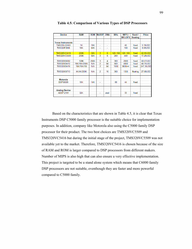
99
Table 4.5: Comparison of Various Types of DSP Processors
Based on the characteristics that are shown in Table 4.5, it is clear that Texas
Instruments DSP C5000 family processor is the suitable choice for implementation
purposes. In addition, company like Motorola also using the C5000 family DSP
processor for their product. The two best choices are TMS320VC5509 and
TMS320VC5416 but during the initial stage of the project, TMS320VC5509 was not
available yet to the market. Therefore, TMS320VC5416 is chosen because of the size
of RAM and ROM is larger compared to DSP processors from different makers.
Number of MIPS is also high that can also ensure a very effective implementation.
This project is targeted to be a stand alone system which means that C6000 family
DSP processors are not suitable, eventhough they are faster and more powerful
compared to C5000 family.
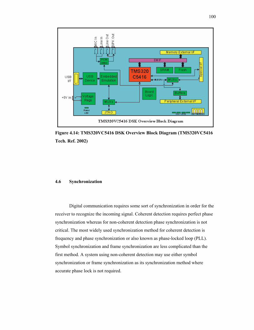
100
Figure 4.14: TMS320VC5416 DSK Overview Block Diagram (TMS320VC5416
Tech. Ref. 2002)
4.6 Synchronization
Digital communication requires some sort of synchronization in order for the
receiver to recognize the incoming signal. Coherent detection requires perfect phase
synchronization whereas for non-coherent detection phase synchronization is not
critical. The most widely used synchronization method for coherent detection is
frequency and phase synchronization or also known as phase-locked loop (PLL).
Symbol synchronization and frame synchronization are less complicated than the
first method. A system using non-coherent detection may use either symbol
synchronization or frame synchronization as its synchronization method where
accurate phase lock is not required.
101
Frequency and phase synchronization or PLL has three basic components
which are a phase detector, a loop filter and a voltage-controlled oscillator (VCO)
(Sklar, 2001). The phase detector measures the phase difference between incoming
signal and local oscillator. The loop filter controls the variations in the phase
difference between incoming signal and local oscillator. And the last component,
VCO is responsible in producing the carrier replica.
Symbol synchronization is classed into two types (Sklar, 2001); non-data-
aided (NDA) and data-aided (DA). The similarity between symbol synchronization
and phase synchronization is that both methods incorporate the process of producing
a replica of a portion the transmitted signal. Symbol synchronization method
generates a square wave at each symbol transition, whereas phase synchronization
needs to replicate an accurate replica of the carrier.
Frame synchronization is the simplest method of detection. This type of
synchronization is required when the information is organized in blocks (Sklar,
2001). Similar to symbol synchronization, frame synchronization is required to
generate a square wave at the frame rate. Systems using non-coherent detection
method employ symbol synchronization or frame synchronization depending on the
organization of the information.
One of the major hurdles during implementation is the synchronization
problem. In the case of coherent PSK demodulation, the receiver is assumed to be
able to generate the reference signals where its phase is identical to the incoming
signal transmitted from the transmitter. These reference signals are compared with
the incoming signals in order to get back the signal, which is modulated, onto the
carrier.
In this project, the need to generate the reference signal is eliminated since
the type of modulation is non-coherent. The complexity of the receiver is reduced
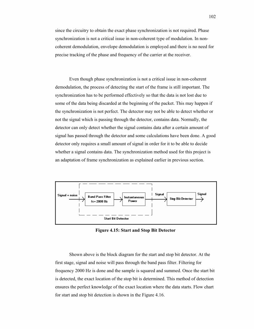
102
since the circuitry to obtain the exact phase synchronization is not required. Phase
synchronization is not a critical issue in non-coherent type of modulation. In non-
coherent demodulation, envelope demodulation is employed and there is no need for
precise tracking of the phase and frequency of the carrier at the receiver.
Even though phase synchronization is not a critical issue in non-coherent
demodulation, the process of detecting the start of the frame is still important. The
synchronization has to be performed effectively so that the data is not lost due to
some of the data being discarded at the beginning of the packet. This may happen if
the synchronization is not perfect. The detector may not be able to detect whether or
not the signal which is passing through the detector, contains data. Normally, the
detector can only detect whether the signal contains data after a certain amount of
signal has passed through the detector and some calculations have been done. A good
detector only requires a small amount of signal in order for it to be able to decide
whether a signal contains data. The synchronization method used for this project is
an adaptation of frame synchronization as explained earlier in previous section.
Figure 4.15: Start and Stop Bit Detector
Shown above is the block diagram for the start and stop bit detector. At the
first stage, signal and noise will pass through the band pass filter. Filtering for
frequency 2000 Hz is done and the sample is squared and summed. Once the start bit
is detected, the exact location of the stop bit is determined. This method of detection
ensures the perfect knowledge of the exact location where the data starts. Flow chart
for start and stop bit detection is shown in the Figure 4.16.
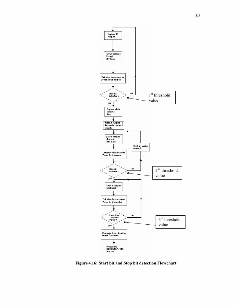
103
Figure 4.16: Start bit and Stop bit detection Flowchart
1st threshold value
2nd threshold value
3rd threshold value
104
Although phase synchronization is not as critical in DQPSK compared to
QPSK, delay in samples due to poor method of detection will introduce error. In
order to overcome this problem, the sample duration of the start bit is increased to
400 samples and sample duration of stop bit is increased to 120 samples. The method
is done in such a way that after the start bit is detected, the exact location of the stop
bit is located by using two methods of calculation. First stop bit calculation
calculates the instantaneous power of 5 samples starting from the supposedly end of
packet location. The total of instantaneous power is compared whether it is larger
than a fixed threshold value. If this condition is fulfilled, second type of stop bit
calculation is executed. If the condition is not fulfilled, the starting point of the
samples is shifted 5 samples backward and the process is repeated.
The second type of stop bit calculation is the backup of the first, in case the
result of first calculation failed to locate the exact location of stop bit. Sample
location calculated previously is shifted 4 samples forward and the value
instantaneous power for the next subsequence 2 samples is calculated. The value of
instantaneous power is then compared with another fixed threshold value. Three
threshold values are used in this project for the purpose of detecting the start bit and
the stop bit. These threshold values are acquired from the experiment when the SNR
is at 16 dB.
4.7 Modulation and Demodulation
Digital modulation is a process where digital data are converted to waveform
that suits the characteristics of the channel. It involves the process of translating
information to radio form, before letting it travel in radio wave. The process starts
from extracting files from the host computer and sending 9 characters each time to
the target DSK board. The 9 characters contain 72 bits of data which are divided into
6 groups. Each of the group which consists of 12 bits of data is then encoded with the
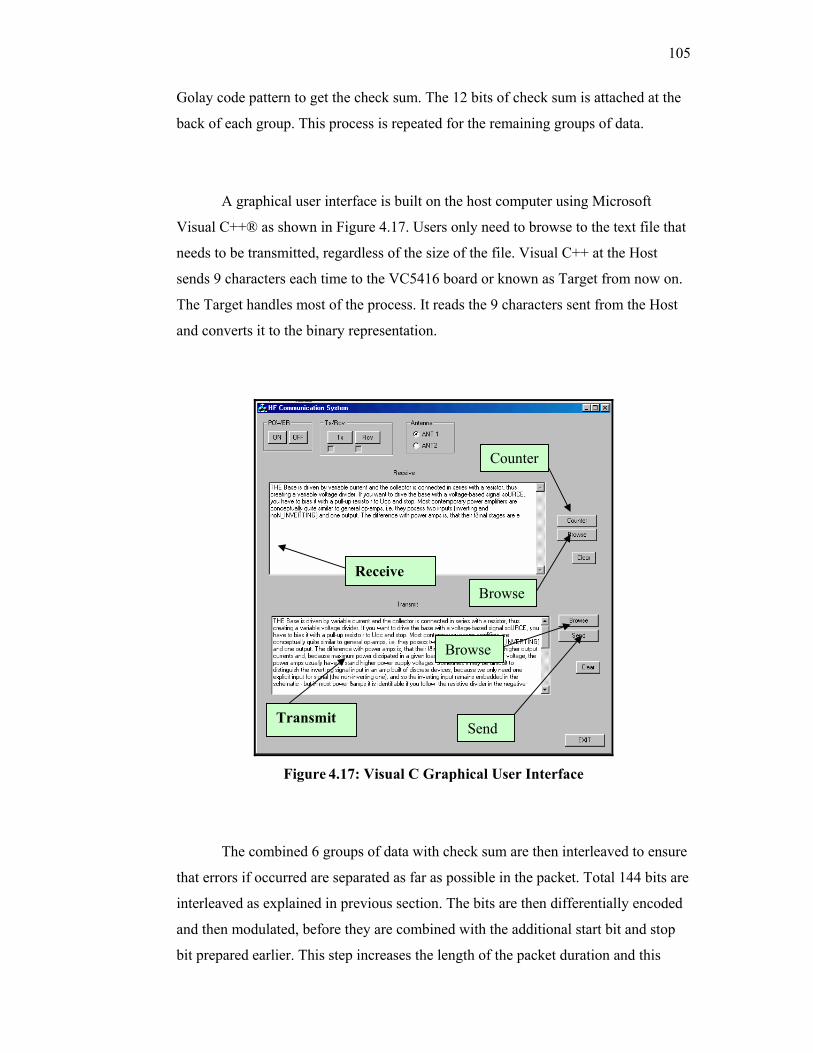
105
Golay code pattern to get the check sum. The 12 bits of check sum is attached at the
back of each group. This process is repeated for the remaining groups of data.
A graphical user interface is built on the host computer using Microsoft
Visual C++® as shown in Figure 4.17. Users only need to browse to the text file that
needs to be transmitted, regardless of the size of the file. Visual C++ at the Host
sends 9 characters each time to the VC5416 board or known as Target from now on.
The Target handles most of the process. It reads the 9 characters sent from the Host
and converts it to the binary representation.
Figure 4.17: Visual C Graphical User Interface
The combined 6 groups of data with check sum are then interleaved to ensure
that errors if occurred are separated as far as possible in the packet. Total 144 bits are
interleaved as explained in previous section. The bits are then differentially encoded
and then modulated, before they are combined with the additional start bit and stop
bit prepared earlier. This step increases the length of the packet duration and this
Transmit
Receive
Counter
Browse
Browse
Send
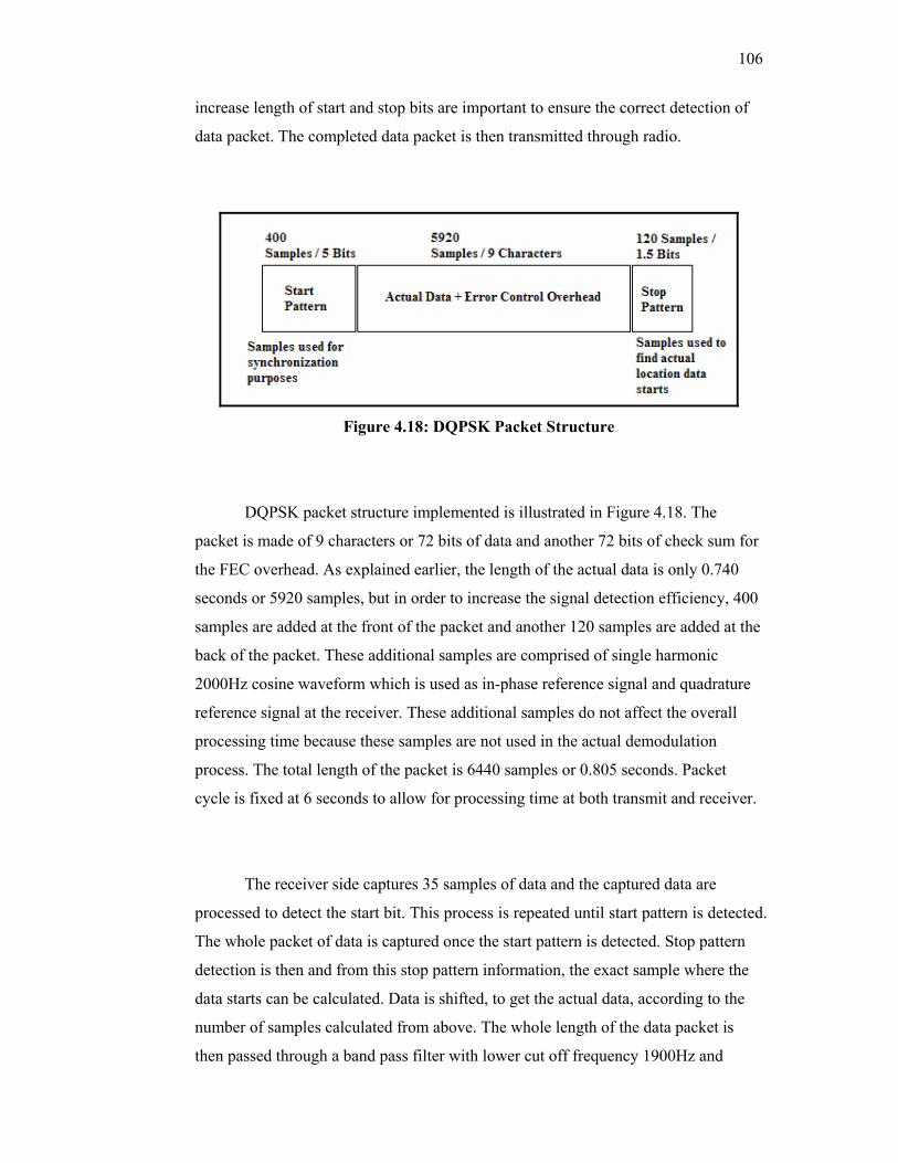
106
increase length of start and stop bits are important to ensure the correct detection of
data packet. The completed data packet is then transmitted through radio.
Figure 4.18: DQPSK Packet Structure
DQPSK packet structure implemented is illustrated in Figure 4.18. The
packet is made of 9 characters or 72 bits of data and another 72 bits of check sum for
the FEC overhead. As explained earlier, the length of the actual data is only 0.740
seconds or 5920 samples, but in order to increase the signal detection efficiency, 400
samples are added at the front of the packet and another 120 samples are added at the
back of the packet. These additional samples are comprised of single harmonic
2000Hz cosine waveform which is used as in-phase reference signal and quadrature
reference signal at the receiver. These additional samples do not affect the overall
processing time because these samples are not used in the actual demodulation
process. The total length of the packet is 6440 samples or 0.805 seconds. Packet
cycle is fixed at 6 seconds to allow for processing time at both transmit and receiver.
The receiver side captures 35 samples of data and the captured data are
processed to detect the start bit. This process is repeated until start pattern is detected.
The whole packet of data is captured once the start pattern is detected. Stop pattern
detection is then and from this stop pattern information, the exact sample where the
data starts can be calculated. Data is shifted, to get the actual data, according to the
number of samples calculated from above. The whole length of the data packet is
then passed through a band pass filter with lower cut off frequency 1900Hz and
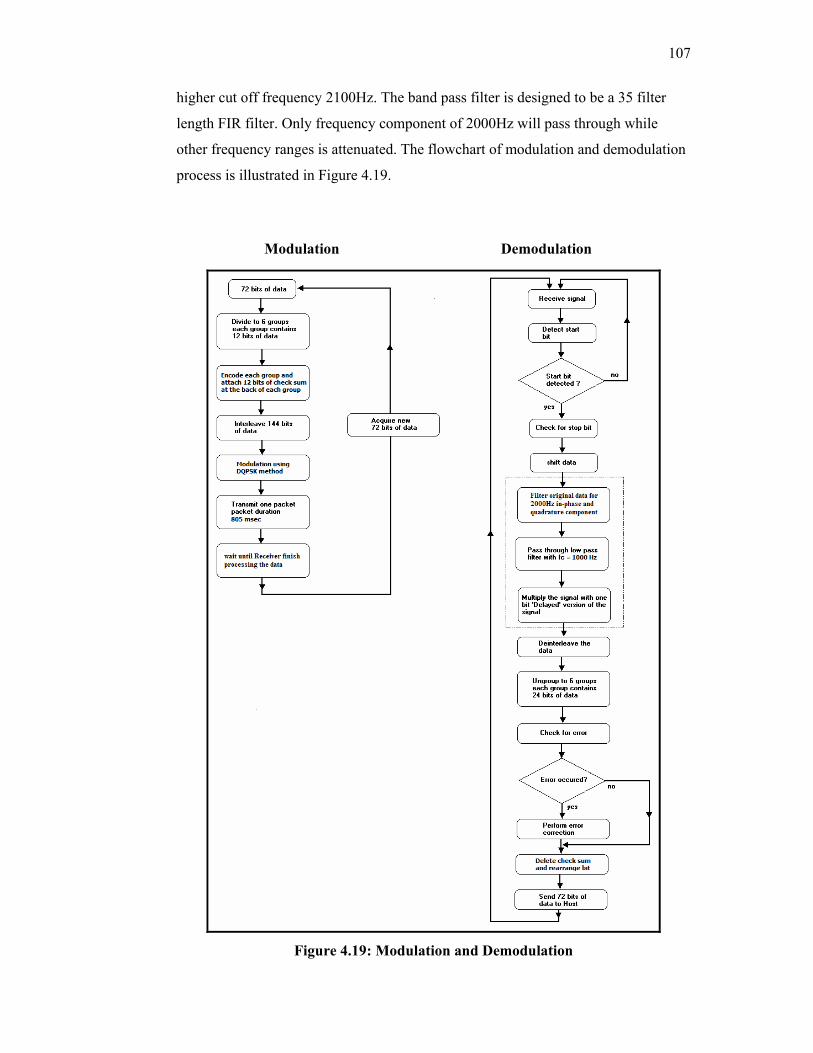
107
higher cut off frequency 2100Hz. The band pass filter is designed to be a 35 filter
length FIR filter. Only frequency component of 2000Hz will pass through while
other frequency ranges is attenuated. The flowchart of modulation and demodulation
process is illustrated in Figure 4.19.
Figure 4.19: Modulation and Demodulation
Modulation Demodulation
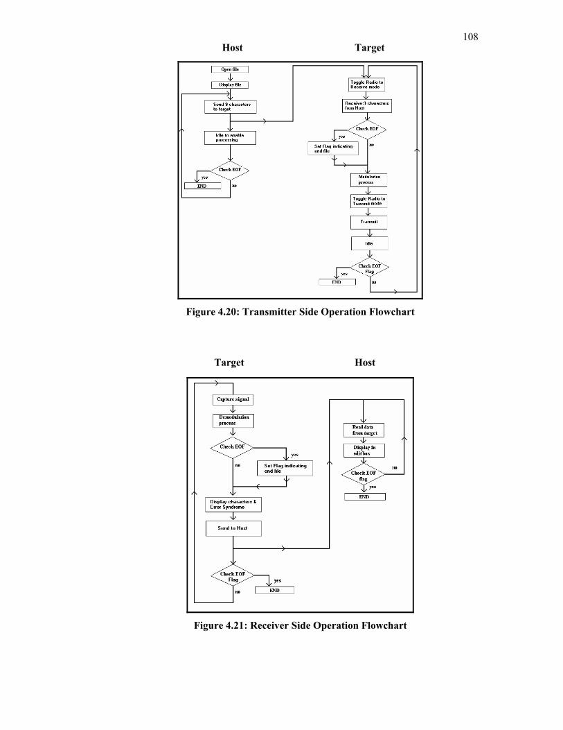
108
Figure 4.20: Transmitter Side Operation Flowchart
Figure 4.21: Receiver Side Operation Flowchart
Host
Target
Target
Host
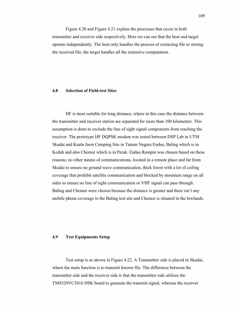
109
Figure 4.20 and Figure 4.21 explain the processes that occur in both
transmitter and receiver side respectively. Here we can see that the host and target
operate independently. The host only handles the process of extracting file or storing
the received file, the target handles all the extensive computation.
4.8 Selection of Field-test Sites
HF is most suitable for long distance, where in this case the distance between
the transmitter and receiver station are separated for more than 100 kilometers. This
assumption is done to exclude the line of sight signal components from reaching the
receiver. The prototype HF DQPSK modem was tested between DSP Lab in UTM
Skudai and Kuala Jasin Camping Site in Taman Negara Endau, Baling which is in
Kedah and also Chemor which is in Perak. Endau Rompin was chosen based on these
reasons; no other means of communications, located in a remote place and far from
Skudai to ensure no ground wave communication, thick forest with a lot of ceiling
coverage that prohibit satellite communication and blocked by mountain range on all
sides to ensure no line of sight communication or VHF signal can pass through.
Baling and Chemor were chosen because the distance is greater and there isn’t any
mobile phone coverage to the Baling test site and Chemor is situated in the lowlands.
4.9 Test Equipments Setup
Test setup is as shown in Figure 4.22. A Transmitter side is placed in Skudai,
where the main function is to transmit known file. The difference between the
transmitter side and the receiver side is that the transmitter side utilizes the
TMS320VC5416 DSK board to generate the transmit signal, whereas the receiver
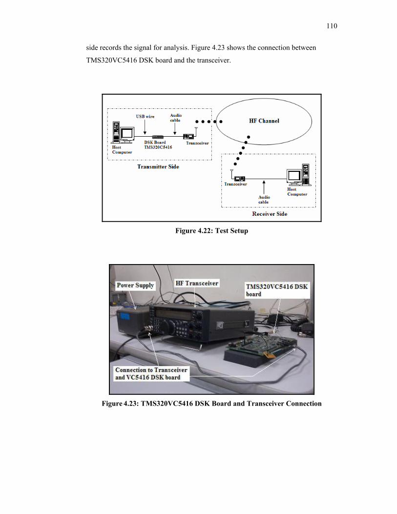
110
side records the signal for analysis. Figure 4.23 shows the connection between
TMS320VC5416 DSK board and the transceiver.
Figure 4.22: Test Setup
Figure 4.23: TMS320VC5416 DSK Board and Transceiver Connection
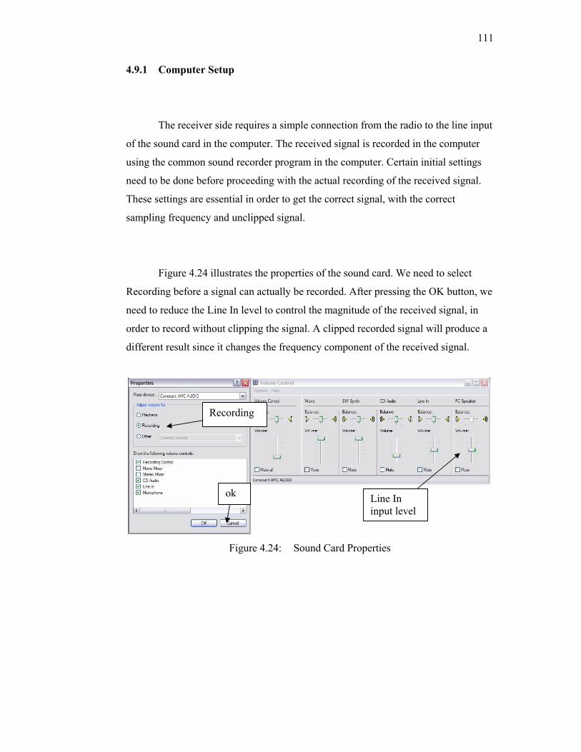
111
4.9.1 Computer Setup
The receiver side requires a simple connection from the radio to the line input
of the sound card in the computer. The received signal is recorded in the computer
using the common sound recorder program in the computer. Certain initial settings
need to be done before proceeding with the actual recording of the received signal.
These settings are essential in order to get the correct signal, with the correct
sampling frequency and unclipped signal.
Figure 4.24 illustrates the properties of the sound card. We need to select
Recording before a signal can actually be recorded. After pressing the OK button, we
need to reduce the Line In level to control the magnitude of the received signal, in
order to record without clipping the signal. A clipped recorded signal will produce a
different result since it changes the frequency component of the received signal.
Figure 4.24: Sound Card Properties
Recording
ok Line In input level
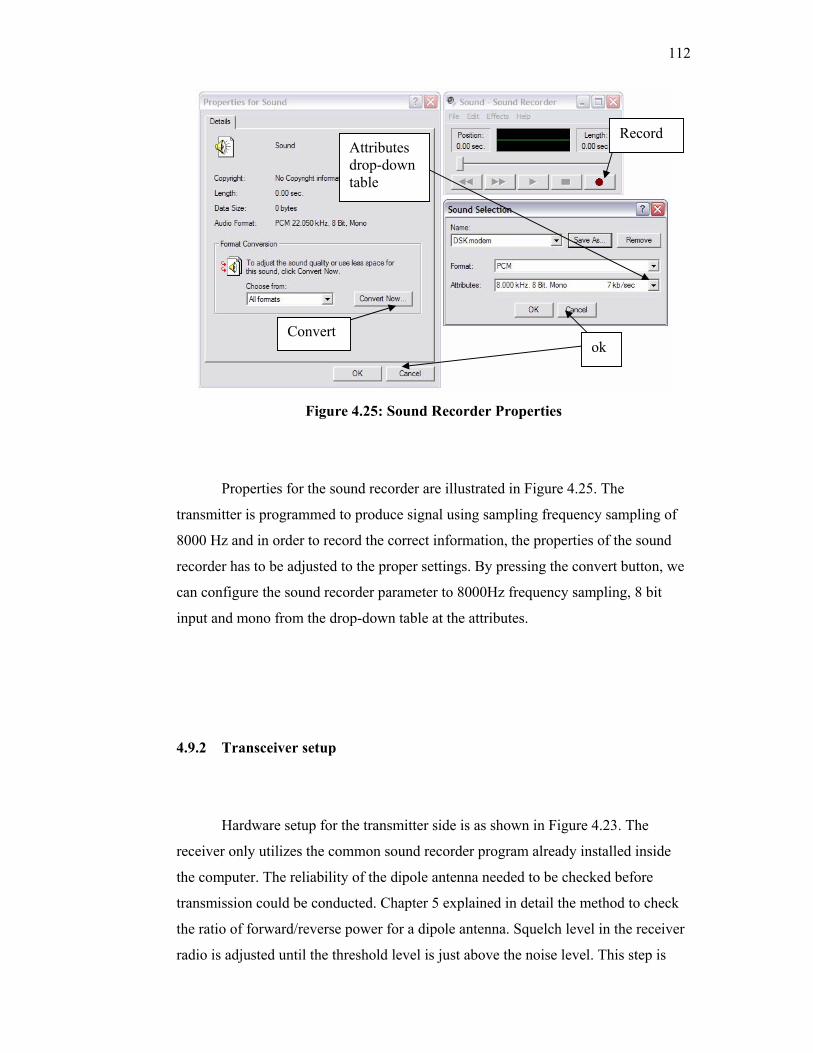
112
Figure 4.25: Sound Recorder Properties
Properties for the sound recorder are illustrated in Figure 4.25. The
transmitter is programmed to produce signal using sampling frequency sampling of
8000 Hz and in order to record the correct information, the properties of the sound
recorder has to be adjusted to the proper settings. By pressing the convert button, we
can configure the sound recorder parameter to 8000Hz frequency sampling, 8 bit
input and mono from the drop-down table at the attributes.
4.9.2 Transceiver setup
Hardware setup for the transmitter side is as shown in Figure 4.23. The
receiver only utilizes the common sound recorder program already installed inside
the computer. The reliability of the dipole antenna needed to be checked before
transmission could be conducted. Chapter 5 explained in detail the method to check
the ratio of forward/reverse power for a dipole antenna. Squelch level in the receiver
radio is adjusted until the threshold level is just above the noise level. This step is
Convert
Attributes drop-down table
Record
ok
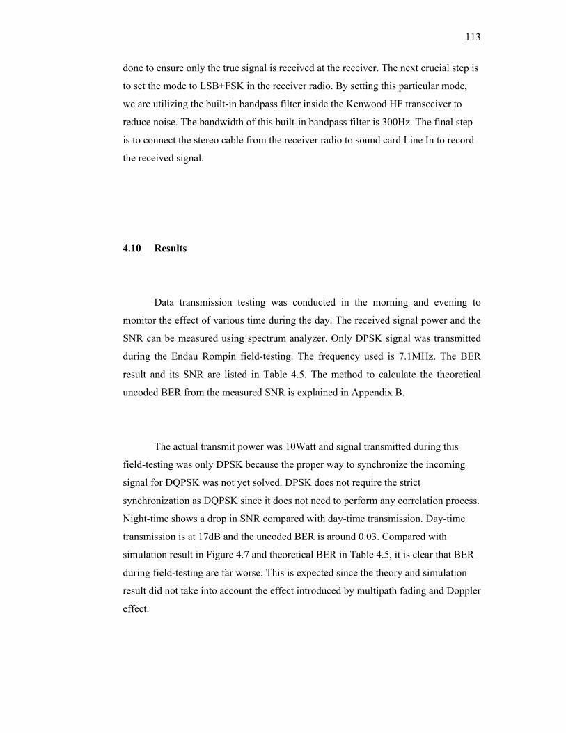
113
done to ensure only the true signal is received at the receiver. The next crucial step is
to set the mode to LSB+FSK in the receiver radio. By setting this particular mode,
we are utilizing the built-in bandpass filter inside the Kenwood HF transceiver to
reduce noise. The bandwidth of this built-in bandpass filter is 300Hz. The final step
is to connect the stereo cable from the receiver radio to sound card Line In to record
the received signal.
4.10 Results
Data transmission testing was conducted in the morning and evening to
monitor the effect of various time during the day. The received signal power and the
SNR can be measured using spectrum analyzer. Only DPSK signal was transmitted
during the Endau Rompin field-testing. The frequency used is 7.1MHz. The BER
result and its SNR are listed in Table 4.5. The method to calculate the theoretical
uncoded BER from the measured SNR is explained in Appendix B.
The actual transmit power was 10Watt and signal transmitted during this
field-testing was only DPSK because the proper way to synchronize the incoming
signal for DQPSK was not yet solved. DPSK does not require the strict
synchronization as DQPSK since it does not need to perform any correlation process.
Night-time shows a drop in SNR compared with day-time transmission. Day-time
transmission is at 17dB and the uncoded BER is around 0.03. Compared with
simulation result in Figure 4.7 and theoretical BER in Table 4.5, it is clear that BER
during field-testing are far worse. This is expected since the theory and simulation
result did not take into account the effect introduced by multipath fading and Doppler
effect.
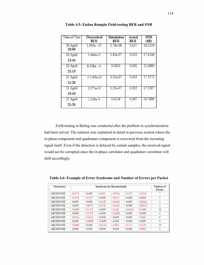
114
Table 4.5: Endau Rompin Field-testing BER and SNR
Field-testing in Baling was conducted after the problem in synchronization
had been solved. The solution was explained in detail in previous section where the
in-phase component and quadrature component is recovered from the incoming
signal itself. Even if the detection is delayed by certain samples, the received signal
would not be corrupted since the in-phase correlator and quadrature correlator will
shift accordingly.
Table 4.6: Example of Error Syndrome and Number of Errors per Packet
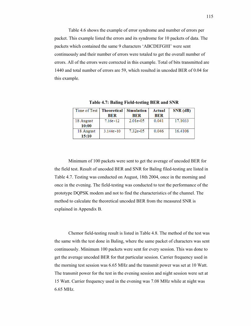
115
Table 4.6 shows the example of error syndrome and number of errors per
packet. This example listed the errors and its syndrome for 10 packets of data. The
packets which contained the same 9 characters ‘ABCDEFGHI’ were sent
continuously and their number of errors were totaled to get the overall number of
errors. All of the errors were corrected in this example. Total of bits transmitted are
1440 and total number of errors are 59, which resulted in uncoded BER of 0.04 for
this example.
Table 4.7: Baling Field-testing BER and SNR
Minimum of 100 packets were sent to get the average of uncoded BER for
the field test. Result of uncoded BER and SNR for Baling filed-testing are listed in
Table 4.7. Testing was conducted on August, 18th 2004, once in the morning and
once in the evening. The field-testing was conducted to test the performance of the
prototype DQPSK modem and not to find the characteristics of the channel. The
method to calculate the theoretical uncoded BER from the measured SNR is
explained in Appendix B.
Chemor field-testing result is listed in Table 4.8. The method of the test was
the same with the test done in Baling, where the same packet of characters was sent
continuously. Minimum 100 packets were sent for every session. This was done to
get the average uncoded BER for that particular session. Carrier frequency used in
the morning test session was 6.65 MHz and the transmit power was set at 10 Watt.
The transmit power for the test in the evening session and night session were set at
15 Watt. Carrier frequency used in the evening was 7.08 MHz while at night was
6.65 MHz.
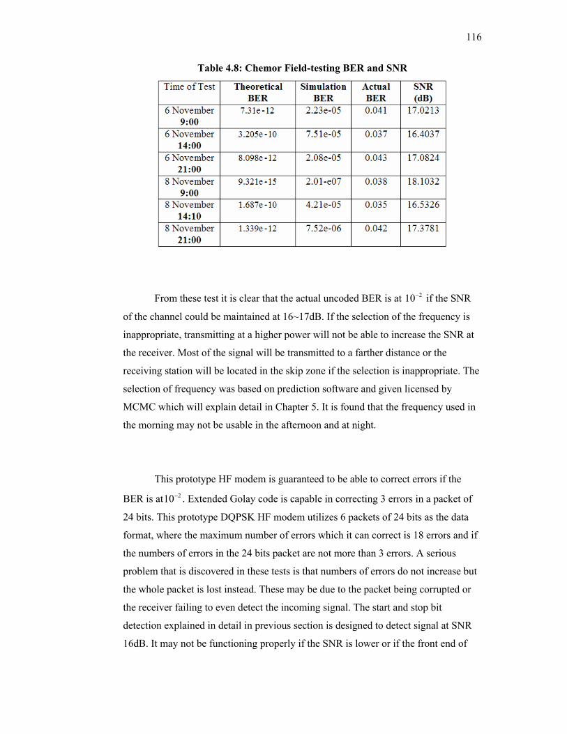
116
Table 4.8: Chemor Field-testing BER and SNR
From these test it is clear that the actual uncoded BER is at 210− if the SNR
of the channel could be maintained at 16~17dB. If the selection of the frequency is
inappropriate, transmitting at a higher power will not be able to increase the SNR at
the receiver. Most of the signal will be transmitted to a farther distance or the
receiving station will be located in the skip zone if the selection is inappropriate. The
selection of frequency was based on prediction software and given licensed by
MCMC which will explain detail in Chapter 5. It is found that the frequency used in
the morning may not be usable in the afternoon and at night.
This prototype HF modem is guaranteed to be able to correct errors if the
BER is at 210− . Extended Golay code is capable in correcting 3 errors in a packet of
24 bits. This prototype DQPSK HF modem utilizes 6 packets of 24 bits as the data
format, where the maximum number of errors which it can correct is 18 errors and if
the numbers of errors in the 24 bits packet are not more than 3 errors. A serious
problem that is discovered in these tests is that numbers of errors do not increase but
the whole packet is lost instead. These may be due to the packet being corrupted or
the receiver failing to even detect the incoming signal. The start and stop bit
detection explained in detail in previous section is designed to detect signal at SNR
16dB. It may not be functioning properly if the SNR is lower or if the front end of
117
the packet itself is corrupted. Examples of corrupted packets are shown in the
Appendix B.
4.11 Conclusion
The results show the comparison of BER and SNR between theoretical,
simulation and experimental. It is found that the prototype is designed to operate at
SNR 16dB. Due to propagation in HF, the prototype found difficulties to fulfill the
objective to transmit secured image over HF radio. However, the research found the
significant in term of modulation technique, channel propagation and error control
which believed could be used to develop stand alone and high speed HF modem in
future.
CHAPTER 5
SYSTEM REQUIREMENTS AND IMPLEMENTATION OF SECURED HF
MESSENGER
Besides an HF modem, another important part in secured HF transmission
system is the application software that executes in a computer. The software will
handle the process of digital information and security before converted to analog
signal by HF modem. Due to the problem of development DQPSK HF modem using
TMS320C5416, the commercialized stand alone modems were purchased. The
application software is needed to control every function of HF modem to ensure
image transmission is possible over HF radio.
5.1 System Components
Basically, the system needs two stations, which are connected to each other
via HF medium. Each station needs a computer, HF modem, transceiver and antenna
to allow them to communicate as shown in Figure 5.1. Usually, the communication
occurs between based station and mobile station. The antenna used could be wide
band or narrow band as long as it supports the compatible range of frequencies for
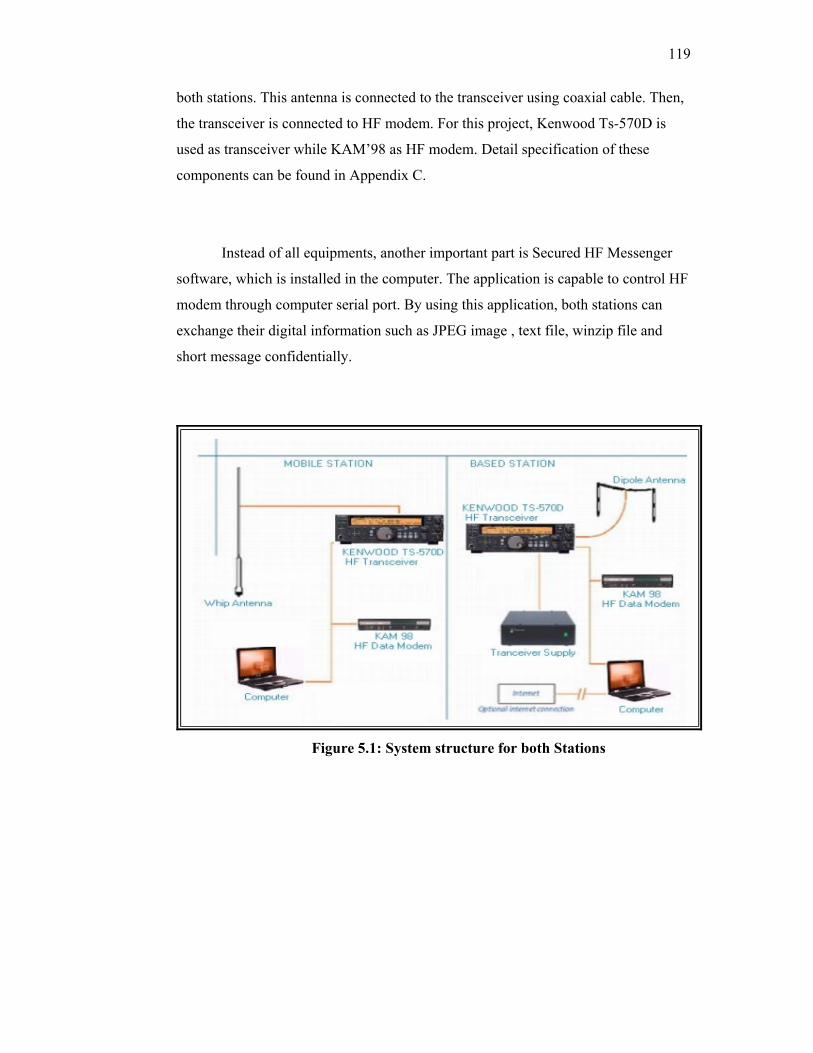
119
both stations. This antenna is connected to the transceiver using coaxial cable. Then,
the transceiver is connected to HF modem. For this project, Kenwood Ts-570D is
used as transceiver while KAM’98 as HF modem. Detail specification of these
components can be found in Appendix C.
Instead of all equipments, another important part is Secured HF Messenger
software, which is installed in the computer. The application is capable to control HF
modem through computer serial port. By using this application, both stations can
exchange their digital information such as JPEG image , text file, winzip file and
short message confidentially.
Figure 5.1: System structure for both Stations
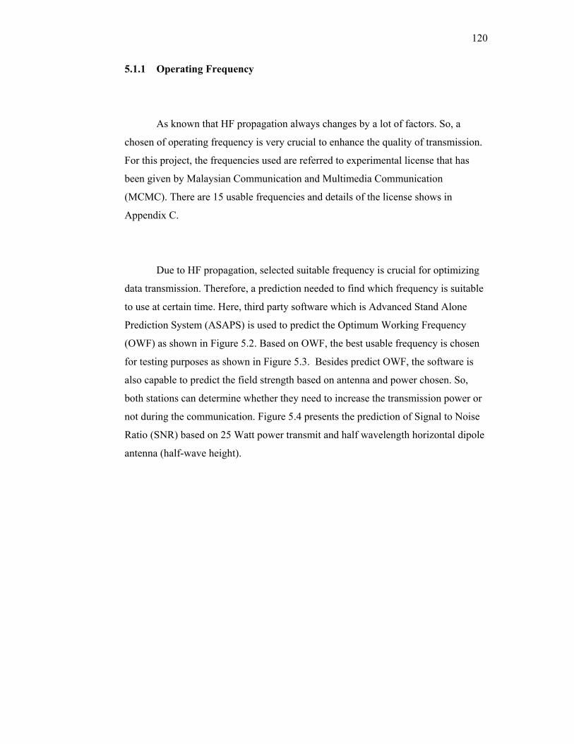
120
5.1.1 Operating Frequency
As known that HF propagation always changes by a lot of factors. So, a
chosen of operating frequency is very crucial to enhance the quality of transmission.
For this project, the frequencies used are referred to experimental license that has
been given by Malaysian Communication and Multimedia Communication
(MCMC). There are 15 usable frequencies and details of the license shows in
Appendix C.
Due to HF propagation, selected suitable frequency is crucial for optimizing
data transmission. Therefore, a prediction needed to find which frequency is suitable
to use at certain time. Here, third party software which is Advanced Stand Alone
Prediction System (ASAPS) is used to predict the Optimum Working Frequency
(OWF) as shown in Figure 5.2. Based on OWF, the best usable frequency is chosen
for testing purposes as shown in Figure 5.3. Besides predict OWF, the software is
also capable to predict the field strength based on antenna and power chosen. So,
both stations can determine whether they need to increase the transmission power or
not during the communication. Figure 5.4 presents the prediction of Signal to Noise
Ratio (SNR) based on 25 Watt power transmit and half wavelength horizontal dipole
antenna (half-wave height).
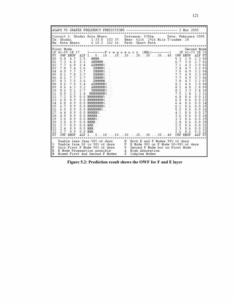
121
Figure 5.2: Prediction result shows the OWF for F and E layer
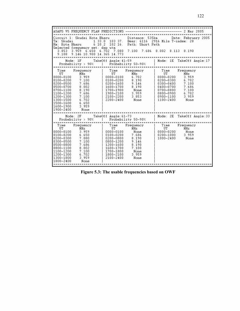
122
Figure 5.3: The usable frequencies based on OWF

123
Figure 5.4: The SNR prediction based on 25Watt power transmit and half
wavelength horizontal dipole antenna (half-wave height).
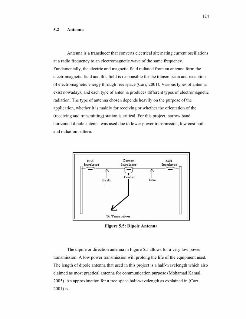
124
5.2 Antenna
Antenna is a transducer that converts electrical alternating current oscillations
at a radio frequency to an electromagnetic wave of the same frequency.
Fundamentally, the electric and magnetic field radiated from an antenna form the
electromagnetic field and this field is responsible for the transmission and reception
of electromagnetic energy through free space (Carr, 2001). Various types of antenna
exist nowadays, and each type of antenna produces different types of electromagnetic
radiation. The type of antenna chosen depends heavily on the purpose of the
application, whether it is mainly for receiving or whether the orientation of the
(receiving and transmitting) station is critical. For this project, narrow band
horizontal dipole antenna was used due to lower power transmission, low cost built
and radiation pattern.
Figure 5.5: Dipole Antenna
The dipole or direction antenna in Figure 5.5 allows for a very low power
transmission. A low power transmission will prolong the life of the equipment used.
The length of dipole antenna that used in this project is a half-wavelength which also
claimed as most practical antenna for communication purpose (Mohamad Kamal,
2005). An approximation for a free space half-wavelength as explained in (Carr,
2001) is
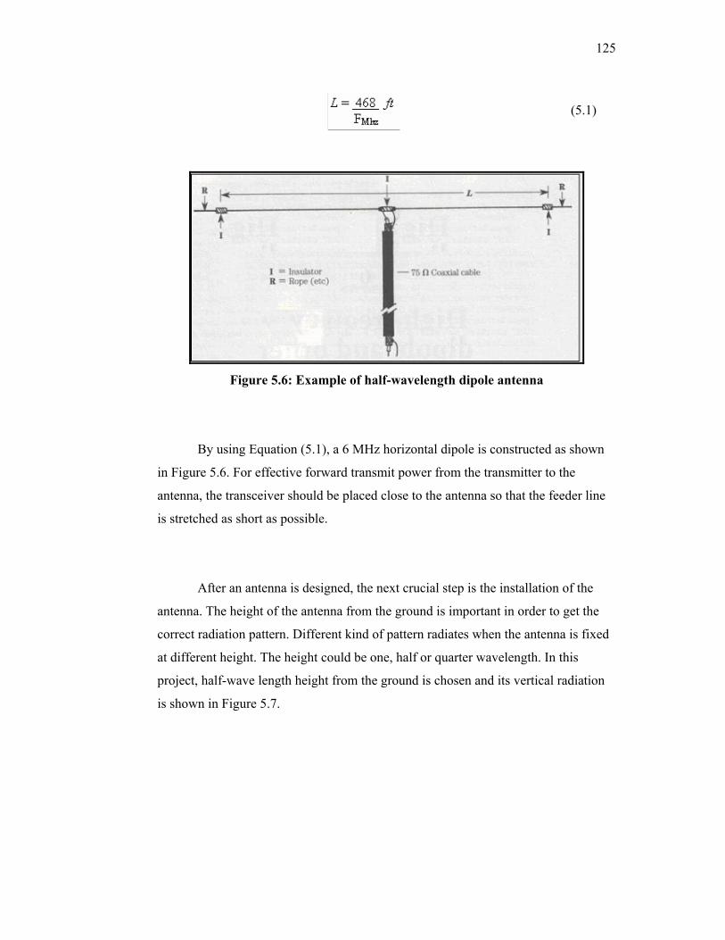
125
(5.1)
Figure 5.6: Example of half-wavelength dipole antenna
By using Equation (5.1), a 6 MHz horizontal dipole is constructed as shown
in Figure 5.6. For effective forward transmit power from the transmitter to the
antenna, the transceiver should be placed close to the antenna so that the feeder line
is stretched as short as possible.
After an antenna is designed, the next crucial step is the installation of the
antenna. The height of the antenna from the ground is important in order to get the
correct radiation pattern. Different kind of pattern radiates when the antenna is fixed
at different height. The height could be one, half or quarter wavelength. In this
project, half-wave length height from the ground is chosen and its vertical radiation
is shown in Figure 5.7.
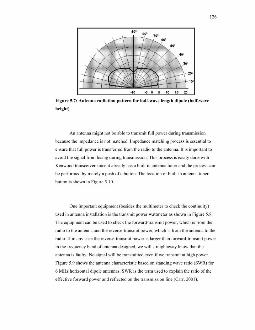
126
Figure 5.7: Antenna radiation pattern for half-wave length dipole (half-wave
height)
An antenna might not be able to transmit full power during transmission
because the impedance is not matched. Impedance matching process is essential to
ensure that full power is transferred from the radio to the antenna. It is important to
avoid the signal from losing during transmission. This process is easily done with
Kenwood transceiver since it already has a built in antenna tuner and the process can
be performed by merely a push of a button. The location of built-in antenna tuner
button is shown in Figure 5.10.
One important equipment (besides the multimeter to check the continuity)
used in antenna installation is the transmit power wattmeter as shown in Figure 5.8.
The equipment can be used to check the forward-transmit power, which is from the
radio to the antenna and the reverse-transmit power, which is from the antenna to the
radio. If in any case the reverse-transmit power is larger than forward-transmit power
in the frequency band of antenna designed, we will straightaway know that the
antenna is faulty. No signal will be transmitted even if we transmit at high power.
Figure 5.9 shows the antenna characteristic based on standing wave ratio (SWR) for
6 MHz horizontal dipole antennas. SWR is the term used to explain the ratio of the
effective forward power and reflected on the transmission line (Carr, 2001).

127
Figure 5.8: Power Wattmeter
Figure 5.9: Dipole Antenna Characteristics
5.3 Transceiver
Kenwood TS-570D (Kenwood Corp, 1998) transceiver is used in this project
for monitoring and field-testing purposes. This transceiver includes a 16-bit DSP unit
to process audio frequencies. By taking maximum advantage of DSP technology, the
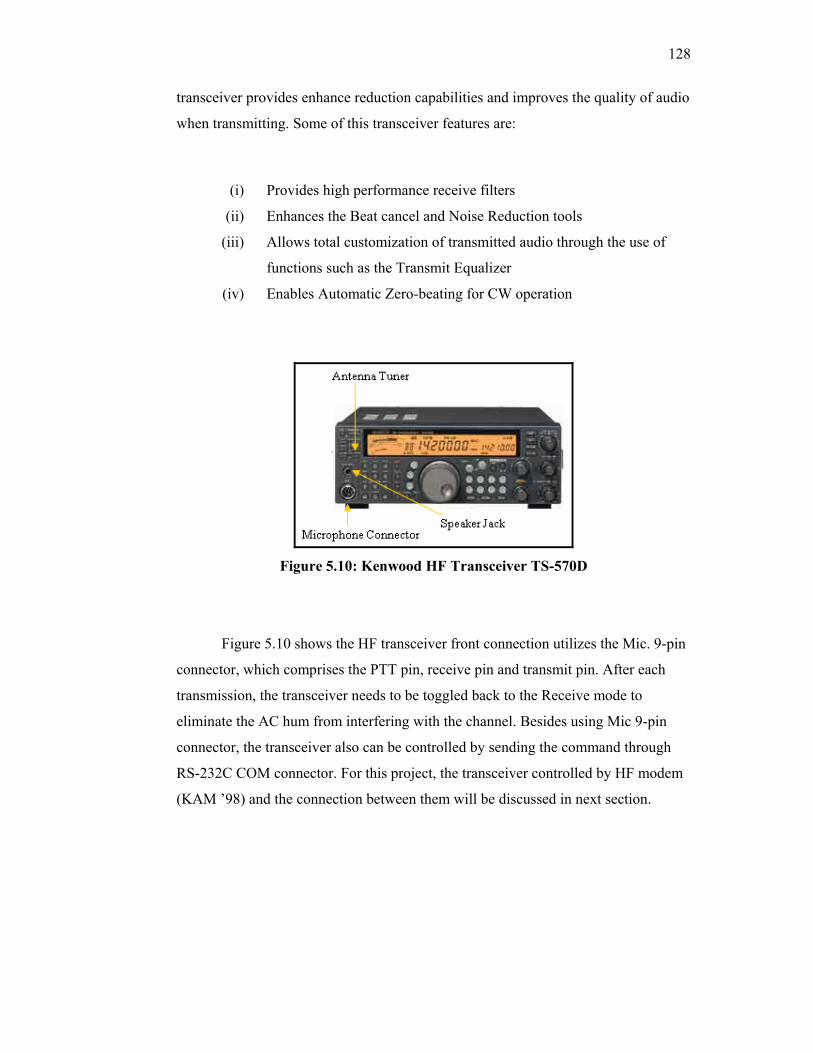
128
transceiver provides enhance reduction capabilities and improves the quality of audio
when transmitting. Some of this transceiver features are:
(i) Provides high performance receive filters
(ii) Enhances the Beat cancel and Noise Reduction tools
(iii) Allows total customization of transmitted audio through the use of
functions such as the Transmit Equalizer
(iv) Enables Automatic Zero-beating for CW operation
Figure 5.10: Kenwood HF Transceiver TS-570D
Figure 5.10 shows the HF transceiver front connection utilizes the Mic. 9-pin
connector, which comprises the PTT pin, receive pin and transmit pin. After each
transmission, the transceiver needs to be toggled back to the Receive mode to
eliminate the AC hum from interfering with the channel. Besides using Mic 9-pin
connector, the transceiver also can be controlled by sending the command through
RS-232C COM connector. For this project, the transceiver controlled by HF modem
(KAM ’98) and the connection between them will be discussed in next section.
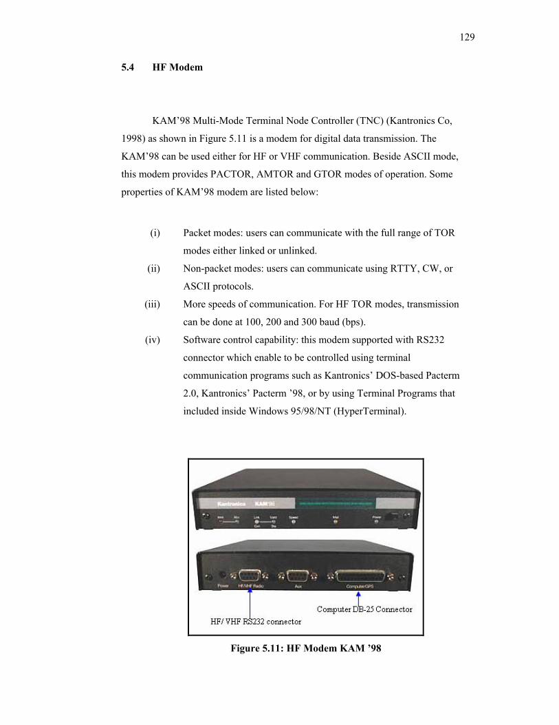
129
5.4 HF Modem
KAM’98 Multi-Mode Terminal Node Controller (TNC) (Kantronics Co,
1998) as shown in Figure 5.11 is a modem for digital data transmission. The
KAM’98 can be used either for HF or VHF communication. Beside ASCII mode,
this modem provides PACTOR, AMTOR and GTOR modes of operation. Some
properties of KAM’98 modem are listed below:
(i) Packet modes: users can communicate with the full range of TOR
modes either linked or unlinked.
(ii) Non-packet modes: users can communicate using RTTY, CW, or
ASCII protocols.
(iii) More speeds of communication. For HF TOR modes, transmission
can be done at 100, 200 and 300 baud (bps).
(iv) Software control capability: this modem supported with RS232
connector which enable to be controlled using terminal
communication programs such as Kantronics’ DOS-based Pacterm
2.0, Kantronics’ Pacterm ’98, or by using Terminal Programs that
included inside Windows 95/98/NT (HyperTerminal).
Figure 5.11: HF Modem KAM ’98
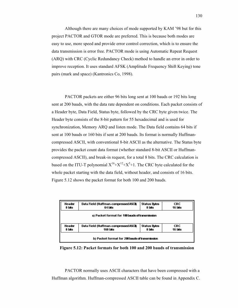
130
Although there are many choices of mode supported by KAM ’98 but for this
project PACTOR and GTOR mode are preferred. This is because both modes are
easy to use, more speed and provide error control correction, which is to ensure the
data transmission is error free. PACTOR mode is using Automatic Repeat Request
(ARQ) with CRC (Cyclic Redundancy Check) method to handle an error in order to
improve reception. It uses standard AFSK (Amplitude Frequency Shift Keying) tone
pairs (mark and space) (Kantronics Co, 1998).
PACTOR packets are either 96 bits long sent at 100 bauds or 192 bits long
sent at 200 bauds, with the data rate dependent on conditions. Each packet consists of
a Header byte, Data Field, Status byte, followed by the CRC byte given twice. The
Header byte consists of the 8-bit pattern for 55 hexadecimal and is used for
synchronization, Memory ARQ and listen mode. The Data field contains 64 bits if
sent at 100 bauds or 160 bits if sent at 200 bauds. Its format is normally Huffman-
compressed ASCII, with conventional 8-bit ASCII as the alternative. The Status byte
provides the packet count data format (whether standard 8-bit ASCII or Huffman-
compressed ASCII), and break-in request, for a total 8 bits. The CRC calculation is
based on the ITU-T polynomial X16+X12+X5+1. The CRC byte calculated for the
whole packet starting with the data field, without header, and consists of 16 bits.
Figure 5.12 shows the packet format for both 100 and 200 bauds.
Figure 5.12: Packet formats for both 100 and 200 bauds of transmission
PACTOR normally uses ASCII characters that have been compressed with a
Huffman algorithm. Huffman-compressed ASCII table can be found in Appendix C.
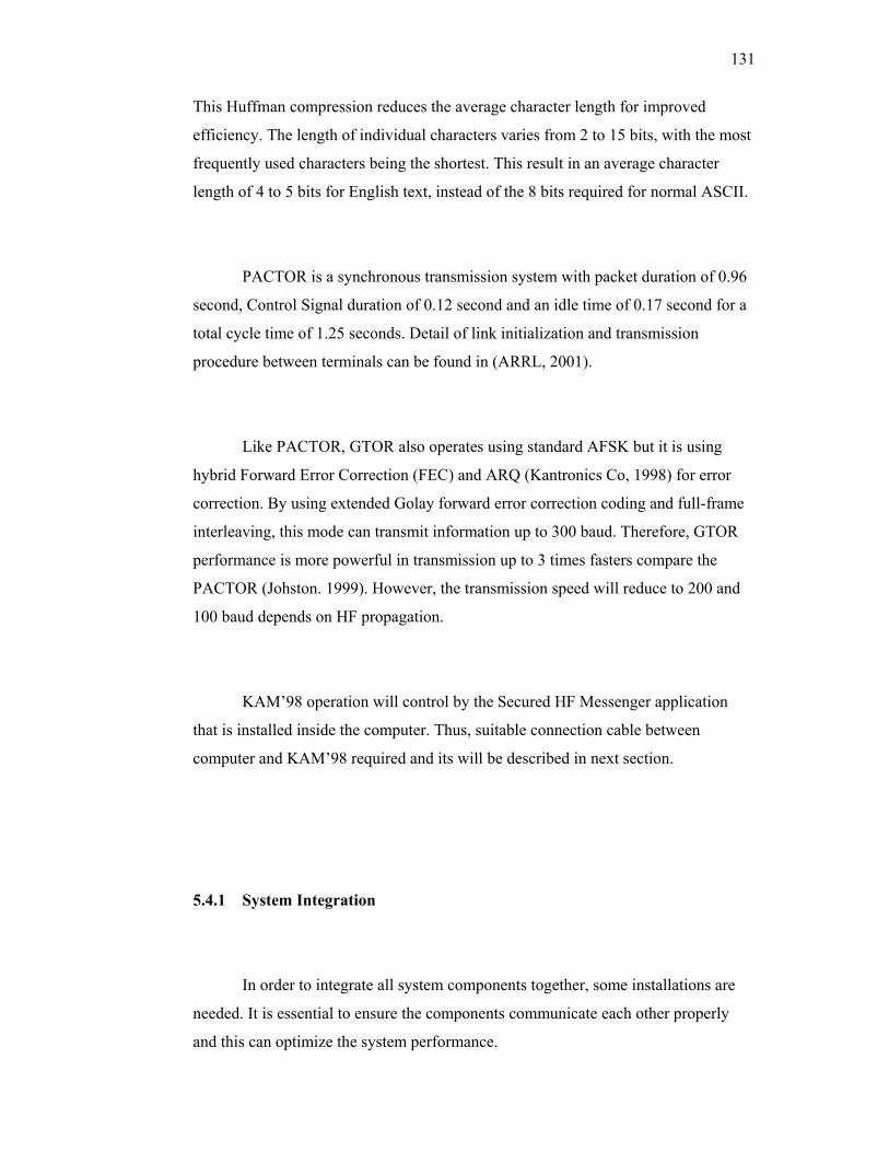
131
This Huffman compression reduces the average character length for improved
efficiency. The length of individual characters varies from 2 to 15 bits, with the most
frequently used characters being the shortest. This result in an average character
length of 4 to 5 bits for English text, instead of the 8 bits required for normal ASCII.
PACTOR is a synchronous transmission system with packet duration of 0.96
second, Control Signal duration of 0.12 second and an idle time of 0.17 second for a
total cycle time of 1.25 seconds. Detail of link initialization and transmission
procedure between terminals can be found in (ARRL, 2001).
Like PACTOR, GTOR also operates using standard AFSK but it is using
hybrid Forward Error Correction (FEC) and ARQ (Kantronics Co, 1998) for error
correction. By using extended Golay forward error correction coding and full-frame
interleaving, this mode can transmit information up to 300 baud. Therefore, GTOR
performance is more powerful in transmission up to 3 times fasters compare the
PACTOR (Johston. 1999). However, the transmission speed will reduce to 200 and
100 baud depends on HF propagation.
KAM’98 operation will control by the Secured HF Messenger application
that is installed inside the computer. Thus, suitable connection cable between
computer and KAM’98 required and its will be described in next section.
5.4.1 System Integration
In order to integrate all system components together, some installations are
needed. It is essential to ensure the components communicate each other properly
and this can optimize the system performance.
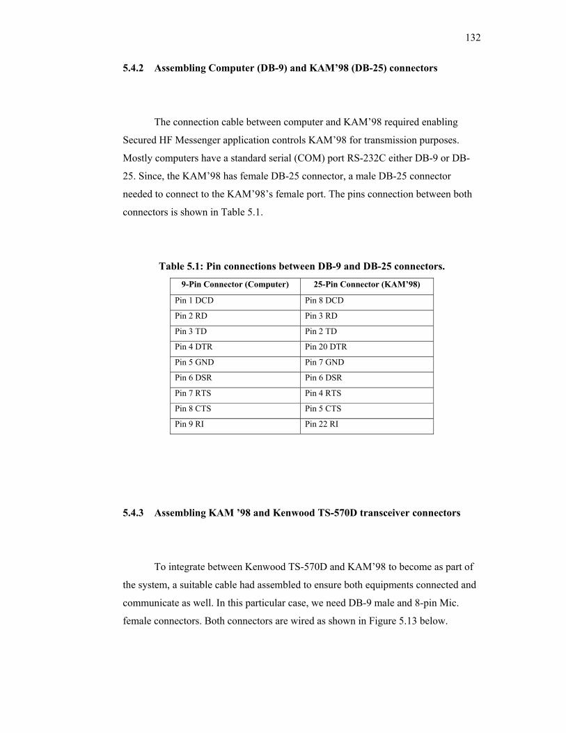
132
5.4.2 Assembling Computer (DB-9) and KAM’98 (DB-25) connectors
The connection cable between computer and KAM’98 required enabling
Secured HF Messenger application controls KAM’98 for transmission purposes.
Mostly computers have a standard serial (COM) port RS-232C either DB-9 or DB-
25. Since, the KAM’98 has female DB-25 connector, a male DB-25 connector
needed to connect to the KAM’98’s female port. The pins connection between both
connectors is shown in Table 5.1.
Table 5.1: Pin connections between DB-9 and DB-25 connectors.
9-Pin Connector (Computer) 25-Pin Connector (KAM’98)
Pin 1 DCD Pin 8 DCD
Pin 2 RD Pin 3 RD
Pin 3 TD Pin 2 TD
Pin 4 DTR Pin 20 DTR
Pin 5 GND Pin 7 GND
Pin 6 DSR Pin 6 DSR
Pin 7 RTS Pin 4 RTS
Pin 8 CTS Pin 5 CTS
Pin 9 RI Pin 22 RI
5.4.3 Assembling KAM ’98 and Kenwood TS-570D transceiver connectors
To integrate between Kenwood TS-570D and KAM’98 to become as part of
the system, a suitable cable had assembled to ensure both equipments connected and
communicate as well. In this particular case, we need DB-9 male and 8-pin Mic.
female connectors. Both connectors are wired as shown in Figure 5.13 below.
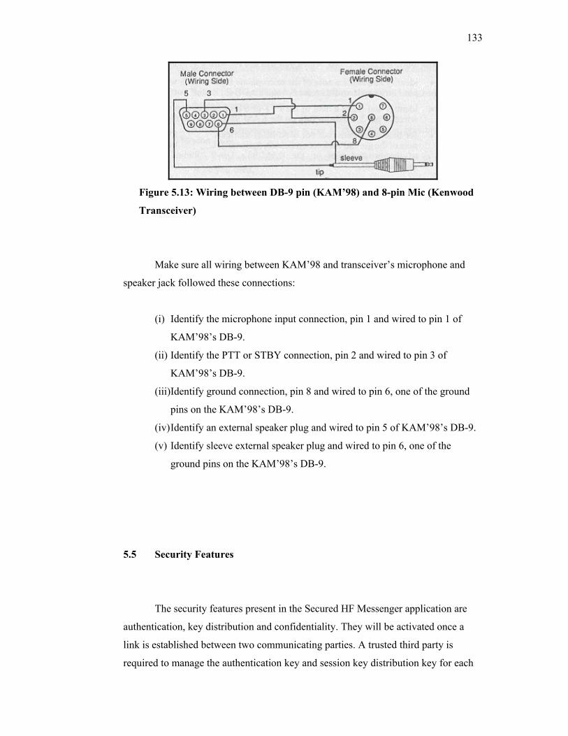
133
Figure 5.13: Wiring between DB-9 pin (KAM’98) and 8-pin Mic (Kenwood
Transceiver)
Make sure all wiring between KAM’98 and transceiver’s microphone and
speaker jack followed these connections:
(i) Identify the microphone input connection, pin 1 and wired to pin 1 of
KAM’98’s DB-9.
(ii) Identify the PTT or STBY connection, pin 2 and wired to pin 3 of
KAM’98’s DB-9.
(iii)Identify ground connection, pin 8 and wired to pin 6, one of the ground
pins on the KAM’98’s DB-9.
(iv) Identify an external speaker plug and wired to pin 5 of KAM’98’s DB-9.
(v) Identify sleeve external speaker plug and wired to pin 6, one of the
ground pins on the KAM’98’s DB-9.
5.5 Security Features
The security features present in the Secured HF Messenger application are
authentication, key distribution and confidentiality. They will be activated once a
link is established between two communicating parties. A trusted third party is
required to manage the authentication key and session key distribution key for each
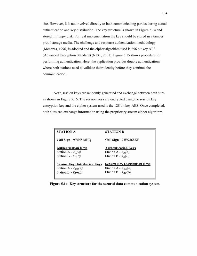
134
site. However, it is not involved directly to both communicating parties during actual
authentication and key distribution. The key structure is shown in Figure 5.14 and
stored in floppy disk. For real implementation the key should be stored in a tamper
proof storage media. The challenge and response authentication methodology
(Menezes, 1996) is adopted and the cipher algorithm used is 256 bit key AES
(Advanced Encryption Standard) (NIST, 2001). Figure 5.15 shows procedure for
performing authentication. Here, the application provides double authentications
where both stations need to validate their identity before they continue the
communication.
Next, session keys are randomly generated and exchange between both sites
as shown in Figure 5.16. The session keys are encrypted using the session key
encryption key and the cipher system used is the 128 bit key AES. Once completed,
both sites can exchange information using the proprietary stream cipher algorithm.
Figure 5.14: Key structure for the secured data communication system.
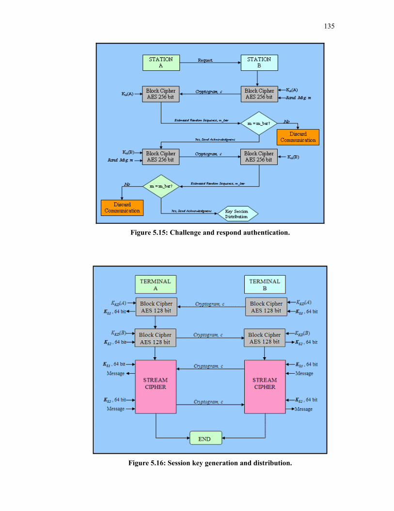
135
Figure 5.15: Challenge and respond authentication.
Figure 5.16: Session key generation and distribution.
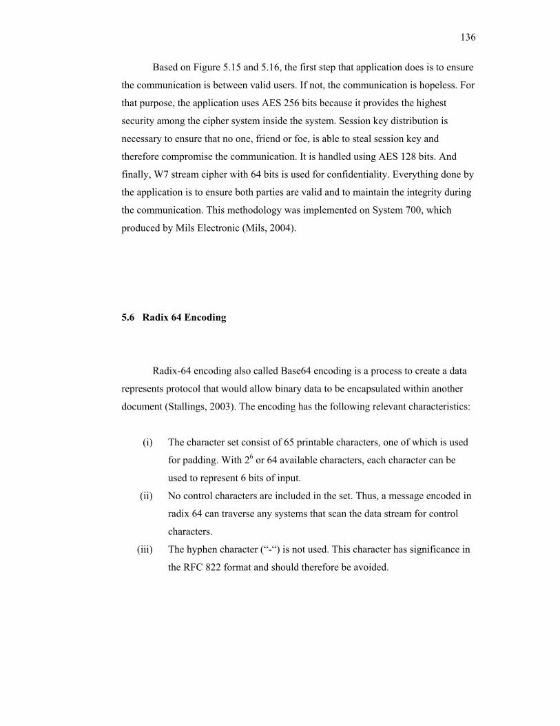
136
Based on Figure 5.15 and 5.16, the first step that application does is to ensure
the communication is between valid users. If not, the communication is hopeless. For
that purpose, the application uses AES 256 bits because it provides the highest
security among the cipher system inside the system. Session key distribution is
necessary to ensure that no one, friend or foe, is able to steal session key and
therefore compromise the communication. It is handled using AES 128 bits. And
finally, W7 stream cipher with 64 bits is used for confidentiality. Everything done by
the application is to ensure both parties are valid and to maintain the integrity during
the communication. This methodology was implemented on System 700, which
produced by Mils Electronic (Mils, 2004).
5.6 Radix 64 Encoding
Radix-64 encoding also called Base64 encoding is a process to create a data
represents protocol that would allow binary data to be encapsulated within another
document (Stallings, 2003). The encoding has the following relevant characteristics:
(i) The character set consist of 65 printable characters, one of which is used
for padding. With 26 or 64 available characters, each character can be
used to represent 6 bits of input.
(ii) No control characters are included in the set. Thus, a message encoded in
radix 64 can traverse any systems that scan the data stream for control
characters.
(iii) The hyphen character (“-“) is not used. This character has significance in
the RFC 822 format and should therefore be avoided.
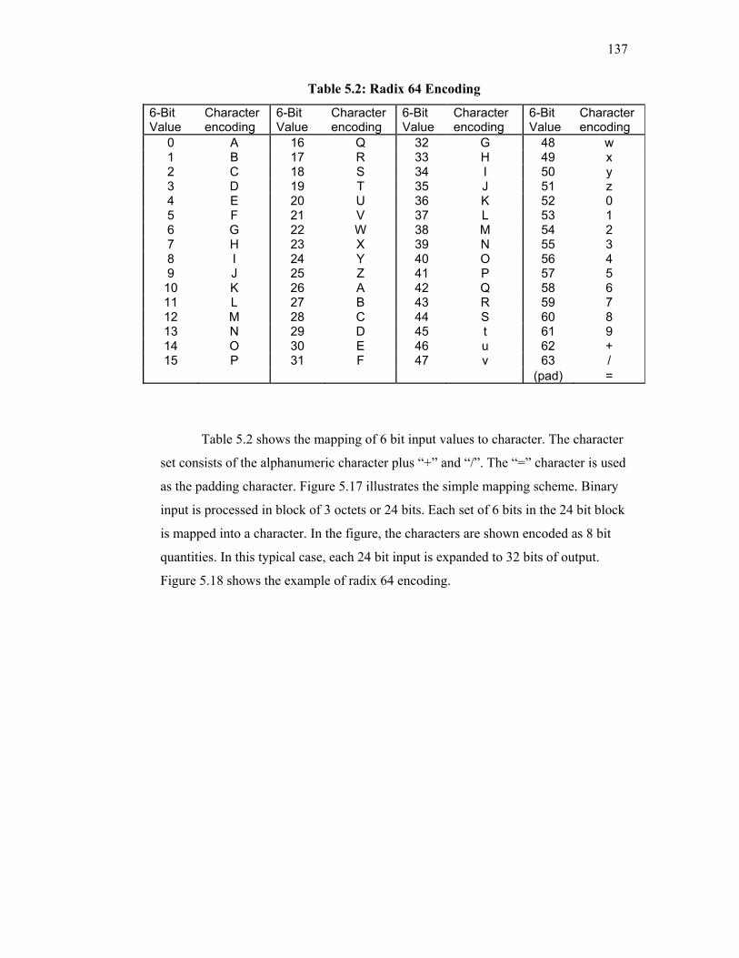
137
Table 5.2: Radix 64 Encoding
6-Bit Value
Character encoding
6-Bit Value
Character encoding
6-Bit Value
Character encoding
6-Bit Value
Character encoding
0 A 16 Q 32 G 48 w 1 B 17 R 33 H 49 x 2 C 18 S 34 I 50 y 3 D 19 T 35 J 51 z 4 E 20 U 36 K 52 0 5 F 21 V 37 L 53 1 6 G 22 W 38 M 54 2 7 H 23 X 39 N 55 3 8 I 24 Y 40 O 56 4 9 J 25 Z 41 P 57 5
10 K 26 A 42 Q 58 6 11 L 27 B 43 R 59 7 12 M 28 C 44 S 60 8 13 N 29 D 45 t 61 9 14 O 30 E 46 u 62 + 15 P 31 F 47 v 63 /
(pad) =
Table 5.2 shows the mapping of 6 bit input values to character. The character
set consists of the alphanumeric character plus “+” and “/”. The “=” character is used
as the padding character. Figure 5.17 illustrates the simple mapping scheme. Binary
input is processed in block of 3 octets or 24 bits. Each set of 6 bits in the 24 bit block
is mapped into a character. In the figure, the characters are shown encoded as 8 bit
quantities. In this typical case, each 24 bit input is expanded to 32 bits of output.
Figure 5.18 shows the example of radix 64 encoding.
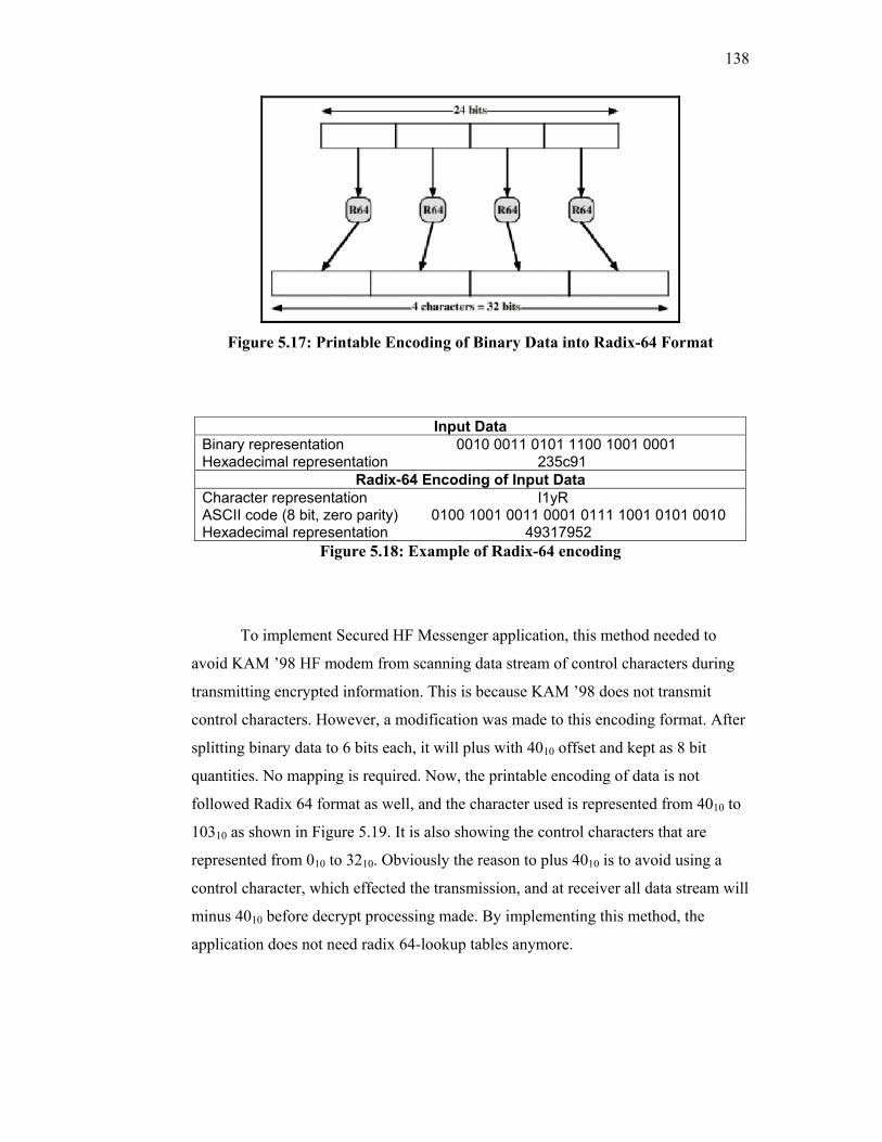
138
Figure 5.17: Printable Encoding of Binary Data into Radix-64 Format
Input Data Binary representation 0010 0011 0101 1100 1001 0001 Hexadecimal representation 235c91
Radix-64 Encoding of Input Data Character representation I1yR ASCII code (8 bit, zero parity) 0100 1001 0011 0001 0111 1001 0101 0010 Hexadecimal representation 49317952
Figure 5.18: Example of Radix-64 encoding
To implement Secured HF Messenger application, this method needed to
avoid KAM ’98 HF modem from scanning data stream of control characters during
transmitting encrypted information. This is because KAM ’98 does not transmit
control characters. However, a modification was made to this encoding format. After
splitting binary data to 6 bits each, it will plus with 4010 offset and kept as 8 bit
quantities. No mapping is required. Now, the printable encoding of data is not
followed Radix 64 format as well, and the character used is represented from 4010 to
10310 as shown in Figure 5.19. It is also showing the control characters that are
represented from 010 to 3210. Obviously the reason to plus 4010 is to avoid using a
control character, which effected the transmission, and at receiver all data stream will
minus 4010 before decrypt processing made. By implementing this method, the
application does not need radix 64-lookup tables anymore.
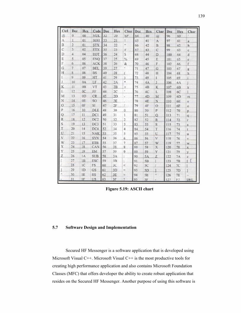
139
Figure 5.19: ASCII chart
5.7 Software Design and Implementation
Secured HF Messenger is a software application that is developed using
Microsoft Visual C++. Microsoft Visual C++ is the most productive tools for
creating high performance application and also contains Microsoft Foundation
Classes (MFC) that offers developer the ability to create robust application that
resides on the Secured HF Messenger. Another purpose of using this software is
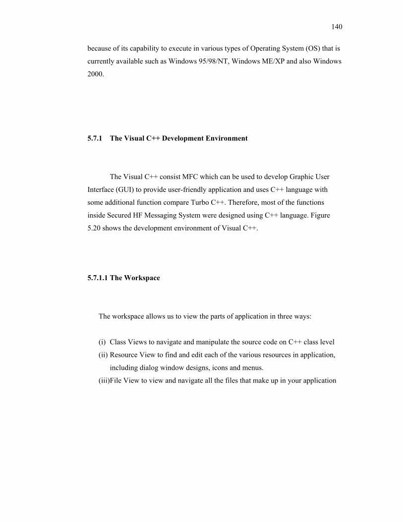
140
because of its capability to execute in various types of Operating System (OS) that is
currently available such as Windows 95/98/NT, Windows ME/XP and also Windows
2000.
5.7.1 The Visual C++ Development Environment
The Visual C++ consist MFC which can be used to develop Graphic User
Interface (GUI) to provide user-friendly application and uses C++ language with
some additional function compare Turbo C++. Therefore, most of the functions
inside Secured HF Messaging System were designed using C++ language. Figure
5.20 shows the development environment of Visual C++.
5.7.1.1 The Workspace
The workspace allows us to view the parts of application in three ways:
(i) Class Views to navigate and manipulate the source code on C++ class level
(ii) Resource View to find and edit each of the various resources in application,
including dialog window designs, icons and menus.
(iii)File View to view and navigate all the files that make up in your application
141
5.7.1.2 The Output Pane
The Output Pane is the place to all compiler progress statement, warning and
error messages. It reopens itself when Visual C++ has any message that need to
display for us.
5.7.1.3 The Editor Area
This is the area where we perform all the editing when using Visual C++.
Everything that has been designed in an application will display here, including
source code.
5.7.1.4 Menu Bar
It consist standard toolbars such as opening and saving files, copying,
pasting, and a variety of other command. The WizardBar toolbars enables us to
perform a number of Class Wizard actions without opening the Class Wizard.
Finally, the Build minibar provides with the build and run commands used to test the
application.
5.7.1.5 Control Palette
It consist several standard control such as static text, edit box, command
button, check box slider, progress bars and so on. Used for graphic user interface
design.
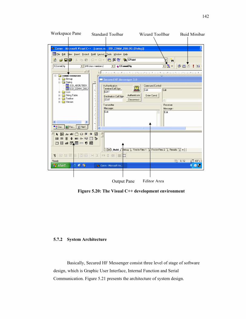
142
Figure 5.20: The Visual C++ development environment
5.7.2 System Architecture
Basically, Secured HF Messenger consist three level of stage of software
design, which is Graphic User Interface, Internal Function and Serial
Communication. Figure 5.21 presents the architecture of system design.
Buid MinibarStandard ToolbarWorkspace Pane Wizard Toollbar
Output Pane Editor Area
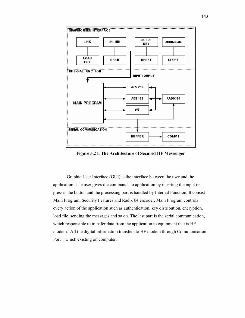
143
Figure 5.21: The Architecture of Secured HF Messenger
Graphic User Interface (GUI) is the interface between the user and the
application. The user gives the commands to application by inserting the input or
presses the button and the processing part is handled by Internal Function. It consist
Main Program, Security Features and Radix 64 encoder. Main Program controls
every action of the application such as authentication, key distribution, encryption,
load file, sending the messages and so on. The last part is the serial communication,
which responsible to transfer data from the application to equipment that is HF
modem. All the digital information transfers to HF modem through Communication
Port 1 which existing on computer.
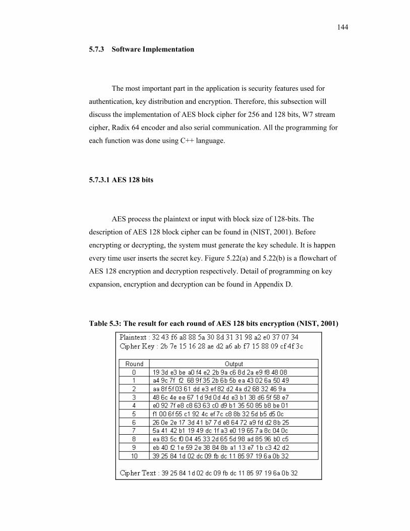
144
5.7.3 Software Implementation
The most important part in the application is security features used for
authentication, key distribution and encryption. Therefore, this subsection will
discuss the implementation of AES block cipher for 256 and 128 bits, W7 stream
cipher, Radix 64 encoder and also serial communication. All the programming for
each function was done using C++ language.
5.7.3.1 AES 128 bits
AES process the plaintext or input with block size of 128-bits. The
description of AES 128 block cipher can be found in (NIST, 2001). Before
encrypting or decrypting, the system must generate the key schedule. It is happen
every time user inserts the secret key. Figure 5.22(a) and 5.22(b) is a flowchart of
AES 128 encryption and decryption respectively. Detail of programming on key
expansion, encryption and decryption can be found in Appendix D.
Table 5.3: The result for each round of AES 128 bits encryption (NIST, 2001)
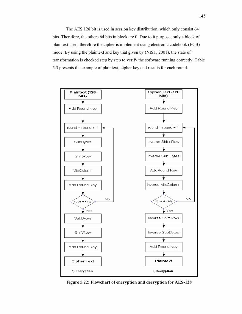
145
The AES 128 bit is used in session key distribution, which only consist 64
bits. Therefore, the others 64 bits in block are 0. Due to it purpose, only a block of
plaintext used, therefore the cipher is implement using electronic codebook (ECB)
mode. By using the plaintext and key that given by (NIST, 2001), the state of
transformation is checked step by step to verify the software running correctly. Table
5.3 presents the example of plaintext, cipher key and results for each round.
Figure 5.22: Flowchart of encryption and decryption for AES-128
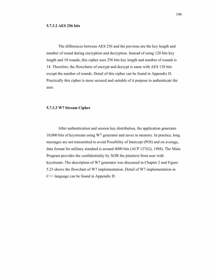
146
5.7.3.2 AES 256 bits
The differences between AES 256 and the previous are the key length and
number of round during encryption and decryption. Instead of using 128 bits key
length and 10 rounds, this cipher uses 256 bits key length and number of rounds is
14. Therefore, the flowcharts of encrypt and decrypt is same with AES 128 bits
except the number of rounds. Detail of this cipher can be found in Appendix D.
Practically this cipher is more secured and suitable of it purpose to authenticate the
user.
5.7.3.3 W7 Stream Cipher
After authentication and session key distribution, the application generates
10,000 bits of keystream using W7 generator and saves in memory. In practice, long
messages are not transmitted to avoid Possibility of Intercept (POI) and on average,
data format for military standard is around 4000 bits (ACP 127(G), 1988). The Main
Program provides the confidentiality by XOR the plaintext from user with
keystream. The description of W7 generator was discussed in Chapter 2 and Figure
5.23 shows the flowchart of W7 implementation. Detail of W7 implementation in
C++ language can be found in Appendix D.
147
Figure 5.23: Flowchart of W7 generator
5.7.3.4 Radix 64 Encoder and Decoder
After encryption process, every bytes of digital information must be encoded
with Radix 64 format before transferring to HF modem via serial communication.
The reverse process occurs at the receiver before decrypting the cryptogram. The
description of Radix 64 was explained in previous section. Detail of Radix 64
encoder and decoder can be found in Appendix D. The function is checked whether
perform properly of not by encode 3 bytes of data as shown in Figure 5.18. The
result must be the same with the expected.
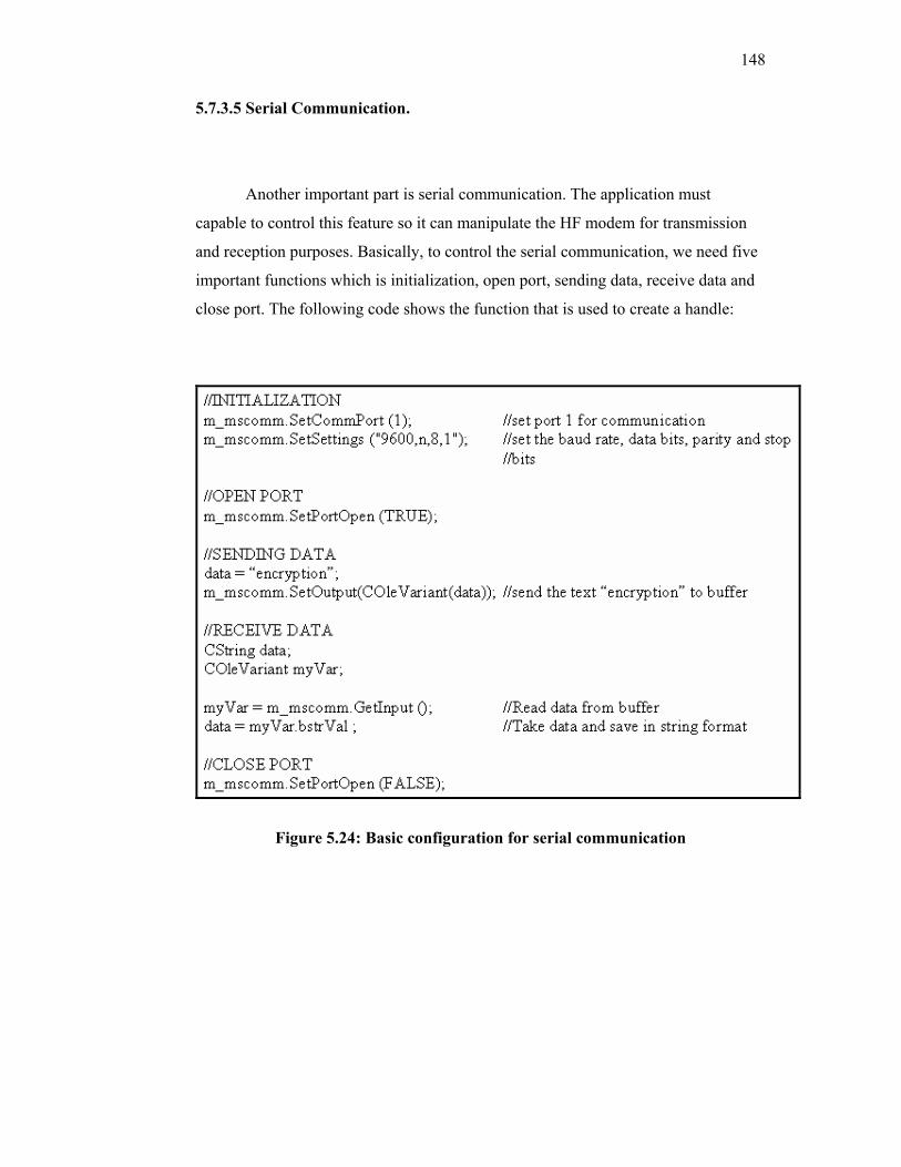
148
5.7.3.5 Serial Communication.
Another important part is serial communication. The application must
capable to control this feature so it can manipulate the HF modem for transmission
and reception purposes. Basically, to control the serial communication, we need five
important functions which is initialization, open port, sending data, receive data and
close port. The following code shows the function that is used to create a handle:
Figure 5.24: Basic configuration for serial communication
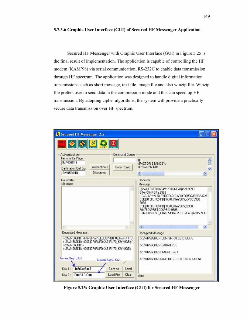
149
5.7.3.6 Graphic User Interface (GUI) of Secured HF Messenger Application
Secured HF Messenger with Graphic User Interface (GUI) in Figure 5.25 is
the final result of implementation. The application is capable of controlling the HF
modem (KAM’98) via serial communication, RS-232C to enable data transmission
through HF spectrum. The application was designed to handle digital information
transmissions such as short message, text file, image file and also winzip file. Winzip
file prefers user to send data in the compression mode and this can speed up HF
transmission. By adopting cipher algorithms, the system will provide a practically
secure data transmission over HF spectrum.
Figure 5.25: Graphic User Interface (GUI) for Secured HF Messenger
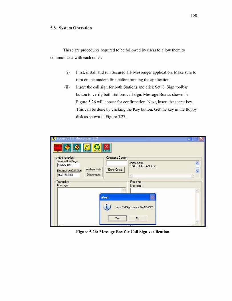
150
5.8 System Operation
These are procedures required to be followed by users to allow them to
communicate with each other:
(i) First, install and run Secured HF Messenger application. Make sure to
turn on the modem first before running the application.
(ii) Insert the call sign for both Stations and click Set C. Sign toolbar
button to verify both stations call sign. Message Box as shown in
Figure 5.26 will appear for confirmation. Next, insert the secret key.
This can be done by clicking the Key button. Get the key in the floppy
disk as shown in Figure 5.27.
Figure 5.26: Message Box for Call Sign verification.
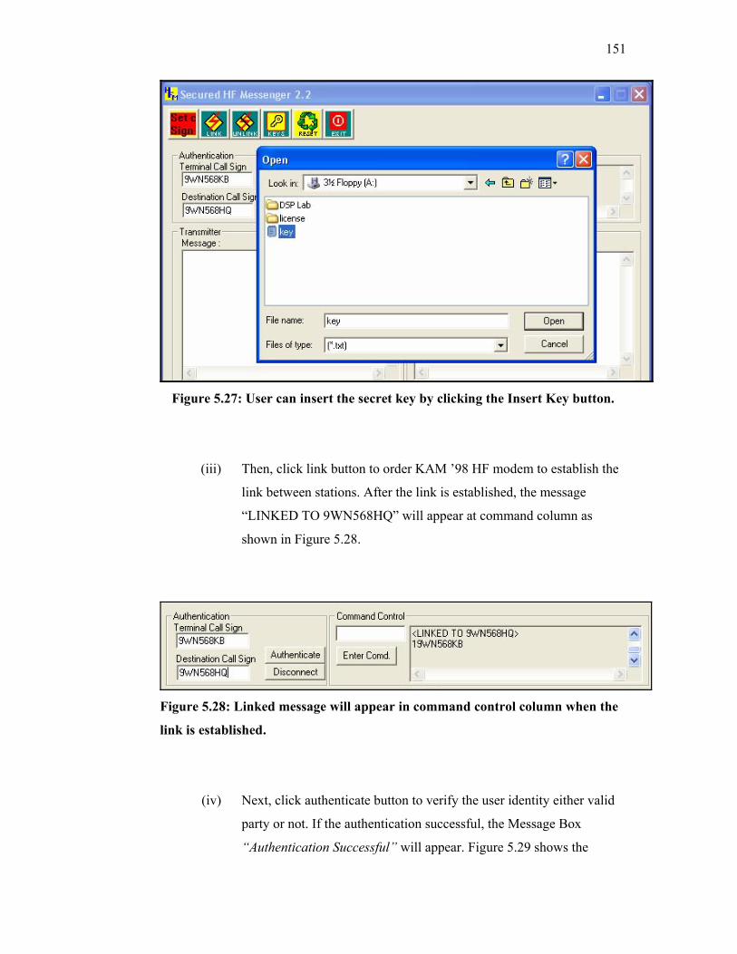
151
Figure 5.27: User can insert the secret key by clicking the Insert Key button.
(iii) Then, click link button to order KAM ’98 HF modem to establish the
link between stations. After the link is established, the message
“LINKED TO 9WN568HQ” will appear at command column as
shown in Figure 5.28.
Figure 5.28: Linked message will appear in command control column when the
link is established.
(iv) Next, click authenticate button to verify the user identity either valid
party or not. If the authentication successful, the Message Box
“Authentication Successful” will appear. Figure 5.29 shows the

152
authentication result and the information inside Key 1 and Key 2
columns are the session keys.
Figure 5.29: Message Box of authentication result will appear either its success
or failed.
(v) After all four steps done successful, then both users can start
communicates each other by typing the message at transmitter column
and the message will send after clicking Send button.
(vi) Beside short message, user also can transmit another document such
as Text File, Image (JPEG) and WinZip File. All these documents
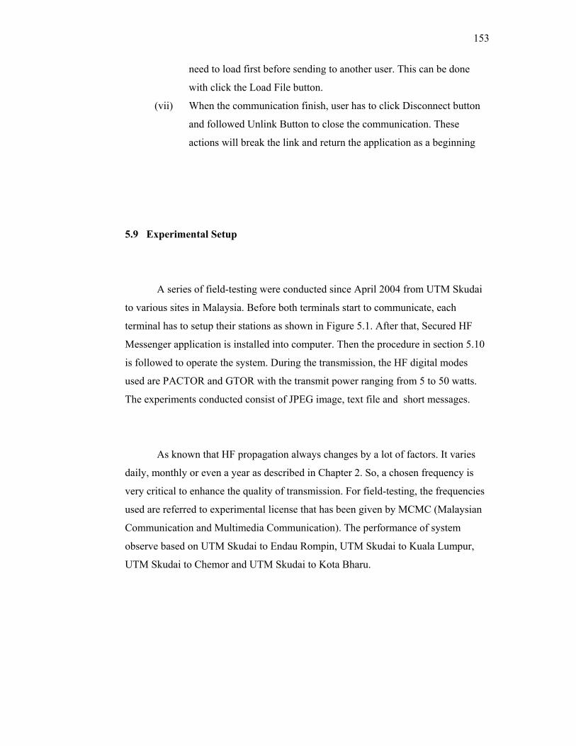
153
need to load first before sending to another user. This can be done
with click the Load File button.
(vii) When the communication finish, user has to click Disconnect button
and followed Unlink Button to close the communication. These
actions will break the link and return the application as a beginning
5.9 Experimental Setup
A series of field-testing were conducted since April 2004 from UTM Skudai
to various sites in Malaysia. Before both terminals start to communicate, each
terminal has to setup their stations as shown in Figure 5.1. After that, Secured HF
Messenger application is installed into computer. Then the procedure in section 5.10
is followed to operate the system. During the transmission, the HF digital modes
used are PACTOR and GTOR with the transmit power ranging from 5 to 50 watts.
The experiments conducted consist of JPEG image, text file and short messages.
As known that HF propagation always changes by a lot of factors. It varies
daily, monthly or even a year as described in Chapter 2. So, a chosen frequency is
very critical to enhance the quality of transmission. For field-testing, the frequencies
used are referred to experimental license that has been given by MCMC (Malaysian
Communication and Multimedia Communication). The performance of system
observe based on UTM Skudai to Endau Rompin, UTM Skudai to Kuala Lumpur,
UTM Skudai to Chemor and UTM Skudai to Kota Bharu.

154
5.9.1 UTM Skudai to Endau Rompin
Taman Negara Endau Rompin managed by Johor National Parks
Corporation, encompasses some 49,000 ha of virgin lowland tropical rainforest.
There are no less than 230 species of birds, 179 species of butterflies and all the great
Malaysian mammals such as the tiger, the elephant, the tapir and the Sumatran
rhinoceros, as well as a host of other animals. Traveling time from UTM Skudai to
the national park by road is 5 hours. The straight-line distance is 120 km.
Figure 5.30: Map of Johor Darul Ta’zim showing the location of UTM Skudai
and Taman Negara Endau Rompin
Before any communication is done, all equipments are needed to setup, as
discussed in previous chapter. The most important part is antenna installation and for
testing purpose 6 MHz half-wavelength dipole was made. The installation of antenna
and equipments layout is shown in Figure 5.31 and 5.32.
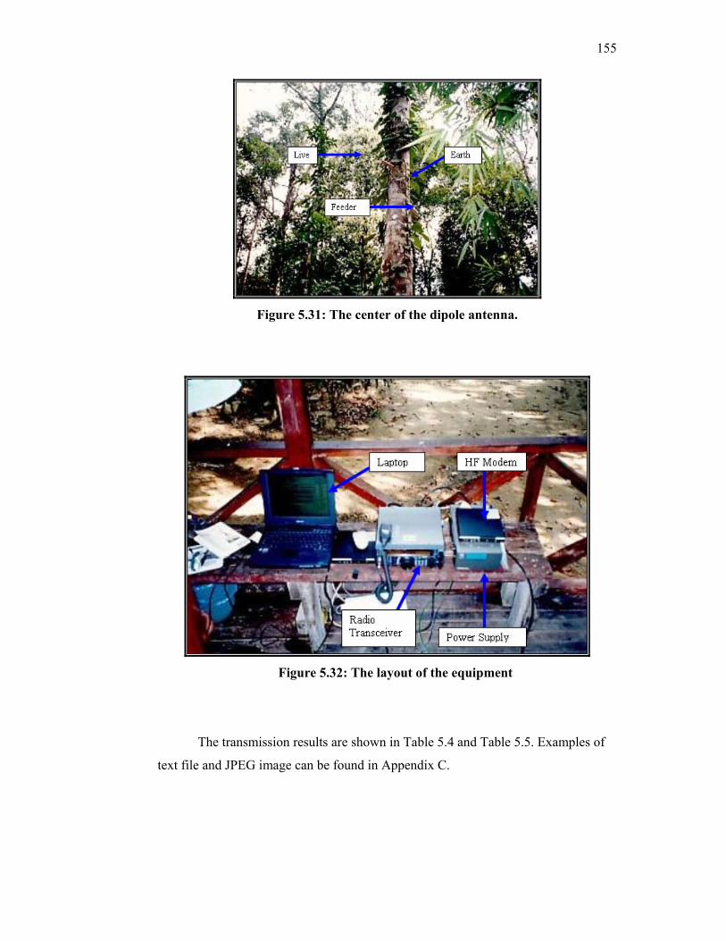
155
Figure 5.31: The center of the dipole antenna.
Figure 5.32: The layout of the equipment
The transmission results are shown in Table 5.4 and Table 5.5. Examples of
text file and JPEG image can be found in Appendix C.
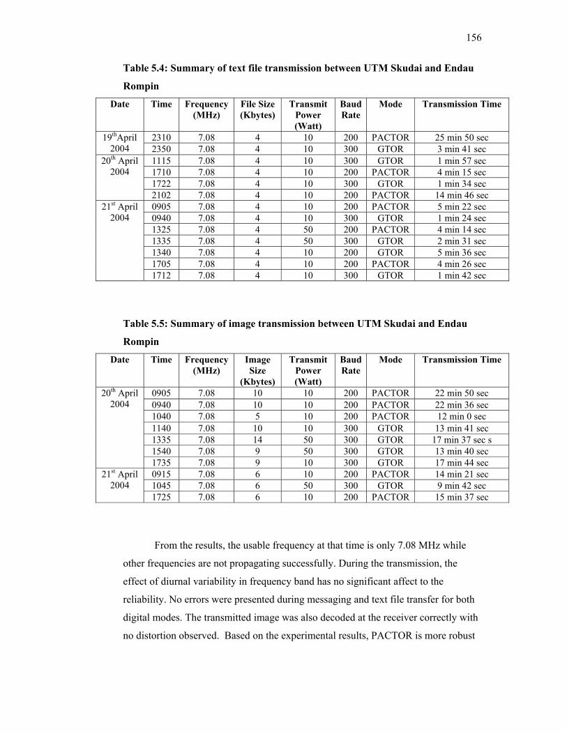
156
Table 5.4: Summary of text file transmission between UTM Skudai and Endau
Rompin
Date Time Frequency (MHz)
File Size (Kbytes)
Transmit Power (Watt)
Baud Rate
Mode Transmission Time
2310 7.08 4 10 200 PACTOR 25 min 50 sec 19thApril 2004 2350 7.08 4 10 300 GTOR 3 min 41 sec
1115 7.08 4 10 300 GTOR 1 min 57 sec 1710 7.08 4 10 200 PACTOR 4 min 15 sec 1722 7.08 4 10 300 GTOR 1 min 34 sec
20th April 2004
2102 7.08 4 10 200 PACTOR 14 min 46 sec 0905 7.08 4 10 200 PACTOR 5 min 22 sec 0940 7.08 4 10 300 GTOR 1 min 24 sec 1325 7.08 4 50 200 PACTOR 4 min 14 sec 1335 7.08 4 50 300 GTOR 2 min 31 sec 1340 7.08 4 10 200 GTOR 5 min 36 sec 1705 7.08 4 10 200 PACTOR 4 min 26 sec
21st April 2004
1712 7.08 4 10 300 GTOR 1 min 42 sec
Table 5.5: Summary of image transmission between UTM Skudai and Endau
Rompin
Date Time Frequency (MHz)
Image Size
(Kbytes)
Transmit Power (Watt)
Baud Rate
Mode Transmission Time
0905 7.08 10 10 200 PACTOR 22 min 50 sec 0940 7.08 10 10 200 PACTOR 22 min 36 sec 1040 7.08 5 10 200 PACTOR 12 min 0 sec 1140 7.08 10 10 300 GTOR 13 min 41 sec 1335 7.08 14 50 300 GTOR 17 min 37 sec s 1540 7.08 9 50 300 GTOR 13 min 40 sec
20th April 2004
1735 7.08 9 10 300 GTOR 17 min 44 sec 0915 7.08 6 10 200 PACTOR 14 min 21 sec 1045 7.08 6 50 300 GTOR 9 min 42 sec
21st April 2004
1725 7.08 6 10 200 PACTOR 15 min 37 sec
From the results, the usable frequency at that time is only 7.08 MHz while
other frequencies are not propagating successfully. During the transmission, the
effect of diurnal variability in frequency band has no significant affect to the
reliability. No errors were presented during messaging and text file transfer for both
digital modes. The transmitted image was also decoded at the receiver correctly with
no distortion observed. Based on the experimental results, PACTOR is more robust
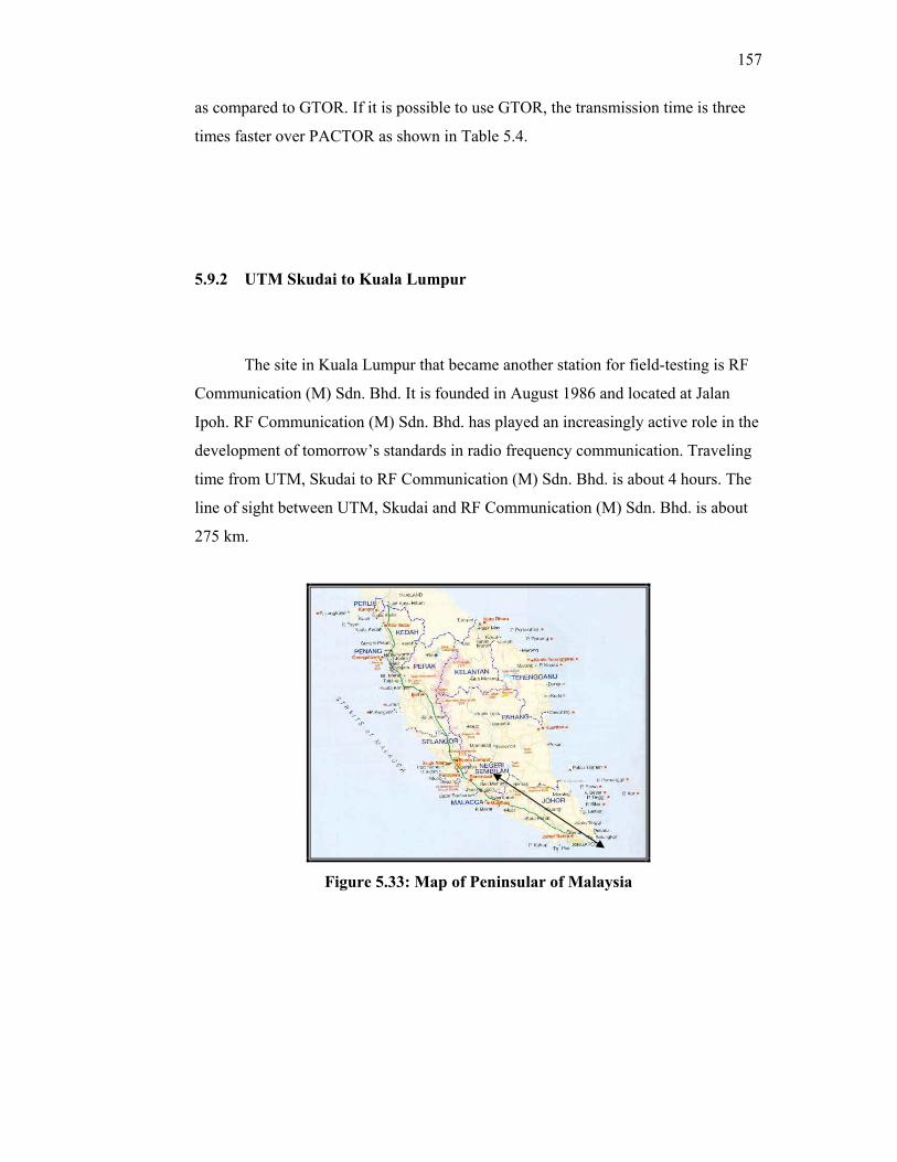
157
as compared to GTOR. If it is possible to use GTOR, the transmission time is three
times faster over PACTOR as shown in Table 5.4.
5.9.2 UTM Skudai to Kuala Lumpur
The site in Kuala Lumpur that became another station for field-testing is RF
Communication (M) Sdn. Bhd. It is founded in August 1986 and located at Jalan
Ipoh. RF Communication (M) Sdn. Bhd. has played an increasingly active role in the
development of tomorrow’s standards in radio frequency communication. Traveling
time from UTM, Skudai to RF Communication (M) Sdn. Bhd. is about 4 hours. The
line of sight between UTM, Skudai and RF Communication (M) Sdn. Bhd. is about
275 km.
Figure 5.33: Map of Peninsular of Malaysia
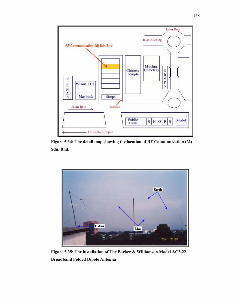
158
Figure 5.34: The detail map showing the location of RF Communication (M)
Sdn. Bhd.
Figure 5.35: The installation of The Barker & Williamson Model AC2-22
Broadband Folded Dipole Antenna
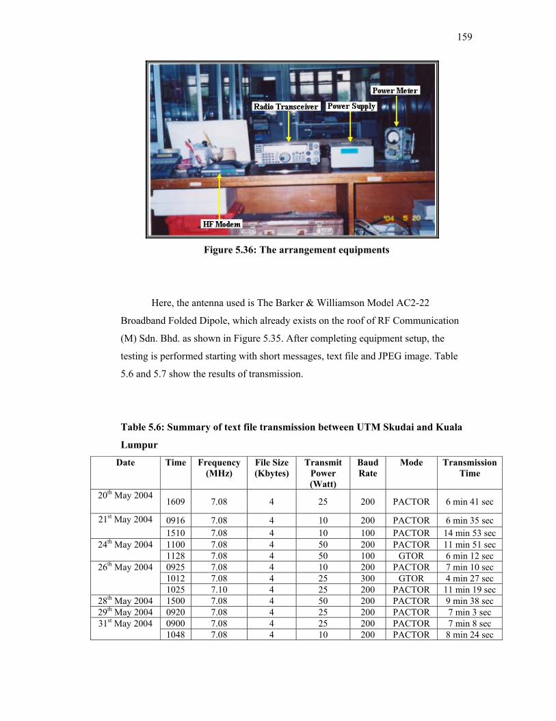
159
Figure 5.36: The arrangement equipments
Here, the antenna used is The Barker & Williamson Model AC2-22
Broadband Folded Dipole, which already exists on the roof of RF Communication
(M) Sdn. Bhd. as shown in Figure 5.35. After completing equipment setup, the
testing is performed starting with short messages, text file and JPEG image. Table
5.6 and 5.7 show the results of transmission.
Table 5.6: Summary of text file transmission between UTM Skudai and Kuala
Lumpur
Date Time Frequency (MHz)
File Size (Kbytes)
Transmit Power (Watt)
Baud Rate
Mode Transmission Time
20th May 2004 1609 7.08 4 25 200 PACTOR 6 min 41 sec
0916 7.08 4 10 200 PACTOR 6 min 35 sec 21st May 2004 1510 7.08 4 10 100 PACTOR 14 min 53 sec 1100 7.08 4 50 200 PACTOR 11 min 51 sec 24th May 2004 1128 7.08 4 50 100 GTOR 6 min 12 sec 0925 7.08 4 10 200 PACTOR 7 min 10 sec 1012 7.08 4 25 300 GTOR 4 min 27 sec
26th May 2004
1025 7.10 4 25 200 PACTOR 11 min 19 sec 28th May 2004 1500 7.08 4 50 200 PACTOR 9 min 38 sec 29th May 2004 0920 7.08 4 25 200 PACTOR 7 min 3 sec
0900 7.08 4 25 200 PACTOR 7 min 8 sec 31st May 2004 1048 7.08 4 10 200 PACTOR 8 min 24 sec
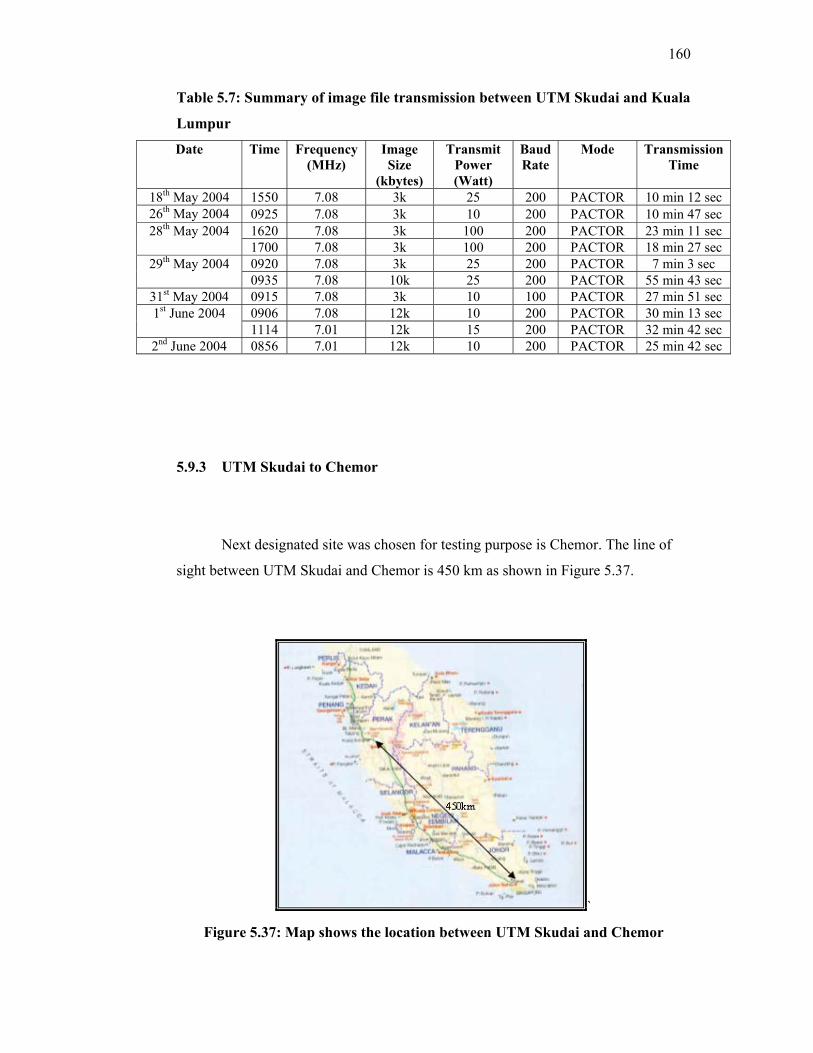
160
Table 5.7: Summary of image file transmission between UTM Skudai and Kuala
Lumpur
Date Time Frequency (MHz)
Image Size
(kbytes)
Transmit Power (Watt)
Baud Rate
Mode Transmission Time
18th May 2004 1550 7.08 3k 25 200 PACTOR 10 min 12 sec 26th May 2004 0925 7.08 3k 10 200 PACTOR 10 min 47 sec
1620 7.08 3k 100 200 PACTOR 23 min 11 sec 28th May 2004 1700 7.08 3k 100 200 PACTOR 18 min 27 sec 0920 7.08 3k 25 200 PACTOR 7 min 3 sec 29th May 2004 0935 7.08 10k 25 200 PACTOR 55 min 43 sec
31st May 2004 0915 7.08 3k 10 100 PACTOR 27 min 51 sec 0906 7.08 12k 10 200 PACTOR 30 min 13 sec 1st June 2004 1114 7.01 12k 15 200 PACTOR 32 min 42 sec
2nd June 2004 0856 7.01 12k 10 200 PACTOR 25 min 42 sec
5.9.3 UTM Skudai to Chemor
Next designated site was chosen for testing purpose is Chemor. The line of
sight between UTM Skudai and Chemor is 450 km as shown in Figure 5.37.
`
Figure 5.37: Map shows the location between UTM Skudai and Chemor
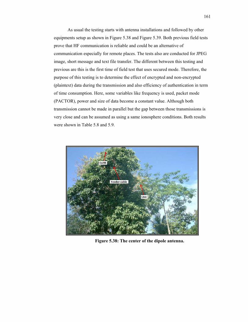
161
As usual the testing starts with antenna installations and followed by other
equipments setup as shown in Figure 5.38 and Figure 5.39. Both previous field tests
prove that HF communication is reliable and could be an alternative of
communication especially for remote places. The tests also are conducted for JPEG
image, short message and text file transfer. The different between this testing and
previous are this is the first time of field test that uses secured mode. Therefore, the
purpose of this testing is to determine the effect of encrypted and non-encrypted
(plaintext) data during the transmission and also efficiency of authentication in term
of time consumption. Here, some variables like frequency is used, packet mode
(PACTOR), power and size of data become a constant value. Although both
transmission cannot be made in parallel but the gap between those transmissions is
very close and can be assumed as using a same ionosphere conditions. Both results
were shown in Table 5.8 and 5.9.
Figure 5.38: The center of the dipole antenna.
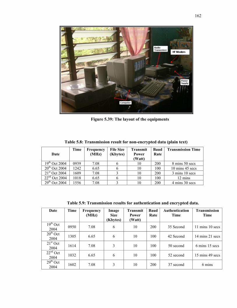
162
Figure 5.39: The layout of the equipments
Table 5.8: Transmission result for non-encrypted data (plain text)
Date
Time Frequency (MHz)
File Size (Kbytes)
Transmit Power (Watt)
Baud Rate
Transmission Time
19th Oct 2004 0939 7.08 6 10 200 8 mins 50 secs 20th Oct 2004 1242 6.65 6 10 100 10 mins 45 secs 21st Oct 2004 1609 7.08 3 10 200 3 mins 10 secs 22nd Oct 2004 1018 6.65 6 10 100 12 mins 29th Oct 2004 1556 7.08 3 10 200 4 mins 30 secs
Table 5.9: Transmission results for authentication and encrypted data.
Date Time Frequency (MHz)
Image Size
(Kbytes)
Transmit Power (Watt)
Baud Rate
Authentication Time
Transmission Time
19th Oct 2004 0950 7.08 6 10 200 35 Second 11 mins 10 secs
20th Oct 2004 1305 6.65 6 10 100 42 Second 14 mins 21 secs
21st Oct 2004 1614 7.08 3 10 100 50 second 6 mins 15 secs
22nd Oct 2004 1032 6.65 6 10 100 52 second 15 mins 49 secs
29th Oct 2004 1602 7.08 3 10 200 37 second 6 mins
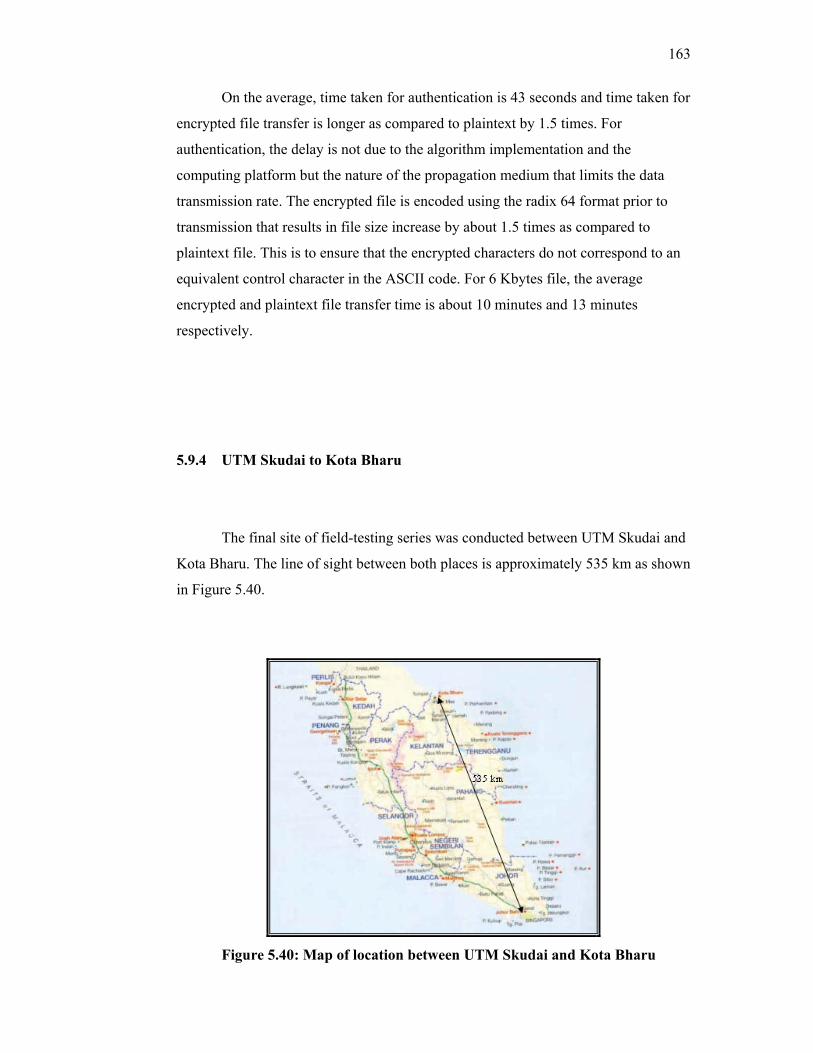
163
On the average, time taken for authentication is 43 seconds and time taken for
encrypted file transfer is longer as compared to plaintext by 1.5 times. For
authentication, the delay is not due to the algorithm implementation and the
computing platform but the nature of the propagation medium that limits the data
transmission rate. The encrypted file is encoded using the radix 64 format prior to
transmission that results in file size increase by about 1.5 times as compared to
plaintext file. This is to ensure that the encrypted characters do not correspond to an
equivalent control character in the ASCII code. For 6 Kbytes file, the average
encrypted and plaintext file transfer time is about 10 minutes and 13 minutes
respectively.
5.9.4 UTM Skudai to Kota Bharu
The final site of field-testing series was conducted between UTM Skudai and
Kota Bharu. The line of sight between both places is approximately 535 km as shown
in Figure 5.40.
Figure 5.40: Map of location between UTM Skudai and Kota Bharu
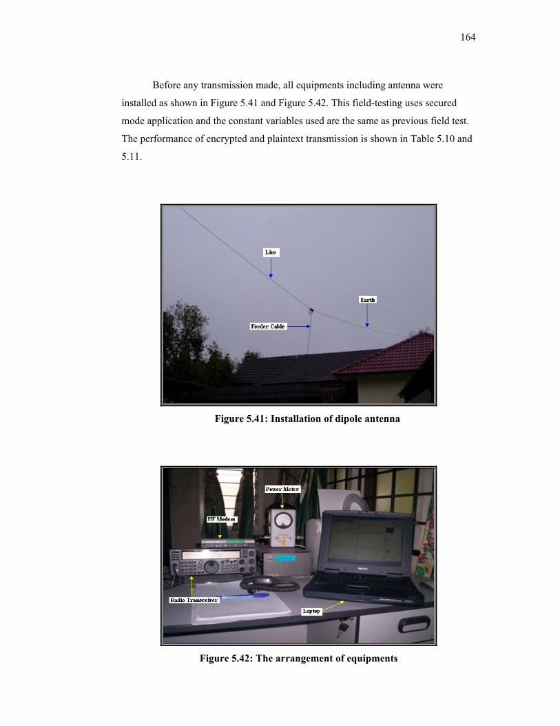
164
Before any transmission made, all equipments including antenna were
installed as shown in Figure 5.41 and Figure 5.42. This field-testing uses secured
mode application and the constant variables used are the same as previous field test.
The performance of encrypted and plaintext transmission is shown in Table 5.10 and
5.11.
Figure 5.41: Installation of dipole antenna
Figure 5.42: The arrangement of equipments
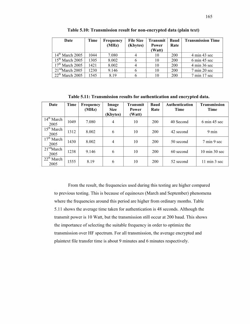
165
Table 5.10: Transmission result for non-encrypted data (plain text)
Table 5.11: Transmission results for authentication and encrypted data.
Date Time Frequency (MHz)
Image Size
(Kbytes)
Transmit Power (Watt)
Baud Rate
Authentication Time
Transmission Time
14th March 2005 1049 7.080 4 10 200 40 Second 6 min 45 sec
15th March 2005 1312 8.002 6 10 200 42 second 9 min
17th March 2005 1430 8.002 4 10 200 50 second 7 min 9 sec
21ndMarch 2005 1238 9.146 6 10 200 60 second 10 min 30 sec
22th March 2005 1555 8.19 6 10 200 52 second 11 min 3 sec
From the result, the frequencies used during this testing are higher compared
to previous testing. This is because of equinoxes (March and September) phenomena
where the frequencies around this period are higher from ordinary months. Table
5.11 shows the average time taken for authentication is 48 seconds. Although the
transmit power is 10 Watt, but the transmission still occur at 200 baud. This shows
the importance of selecting the suitable frequency in order to optimize the
transmission over HF spectrum. For all transmission, the average encrypted and
plaintext file transfer time is about 9 minutes and 6 minutes respectively.
Date Time Frequency (MHz)
File Size (Kbytes)
Transmit Power (Watt)
Baud Rate
Transmission Time
14th March 2005 1044 7.080 4 10 200 4 min 43 sec 15th March 2005 1305 8.002 6 10 200 6 min 45 sec 17th March 2005 1421 8.002 4 10 200 4 min 36 sec 21ndMarch 2005 1230 9.146 6 10 200 7 min 20 sec 22th March 2005 1545 8.19 6 10 200 7 min 17 sec
166
5.10 Conclusion
Although several equipment were purchased, but the system is classified as
low cost system structure because it only used commercial equipments such as
computer, HF modem (KAM’98), HF radio (Kenwood) and antenna. With a little
setup and installation, all equipments were integrated to become a system. Based on
field-testing, Secured HF Messenger is user-friendly and by following a few steps as
mentioned, users can use this application to exchange their digital information over
HF confidentially.

CHAPTER 6
LONG RANGE HF TELEMETRY SYSTEM
Malaysia is a maritime nation where much of its wealth in natural resources
and assets lie within the 200 nautical mile economic exclusive zone (EEZ). Example
of natural resources and assets includes oil and gas fields, fishing areas, shipping
lanes, ports, and ships. From international perspective, the Straits of Malacca is an
important waterway for international trade between Europe and the Far East with a
traffic flow of 1000 vessels a day. Thus, it is important for maritime organizations
such as Jabatan Laut Semenanjung Malaysia to ensure maximum reliability of their
navigation aids assets such as light houses and beacons.
For fleet operators, monitoring of movement of ships is important to ensure
that product deliveries and services are on schedule with safety on passage. Any
deviation from route and emergencies should be alerted on time to the fleet operators
as well to the appropriate maritime organizations for further actions. Both
applications can be best served using long range telemetry systems (Barr, 2004):
light house telemetry system and vessel tracking system.
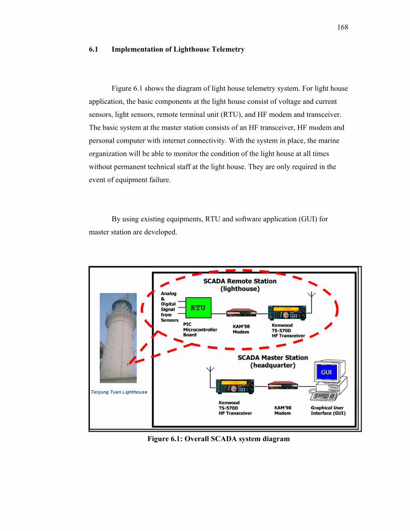
168
6.1 Implementation of Lighthouse Telemetry
Figure 6.1 shows the diagram of light house telemetry system. For light house
application, the basic components at the light house consist of voltage and current
sensors, light sensors, remote terminal unit (RTU), and HF modem and transceiver.
The basic system at the master station consists of an HF transceiver, HF modem and
personal computer with internet connectivity. With the system in place, the marine
organization will be able to monitor the condition of the light house at all times
without permanent technical staff at the light house. They are only required in the
event of equipment failure.
By using existing equipments, RTU and software application (GUI) for
master station are developed.
Figure 6.1: Overall SCADA system diagram
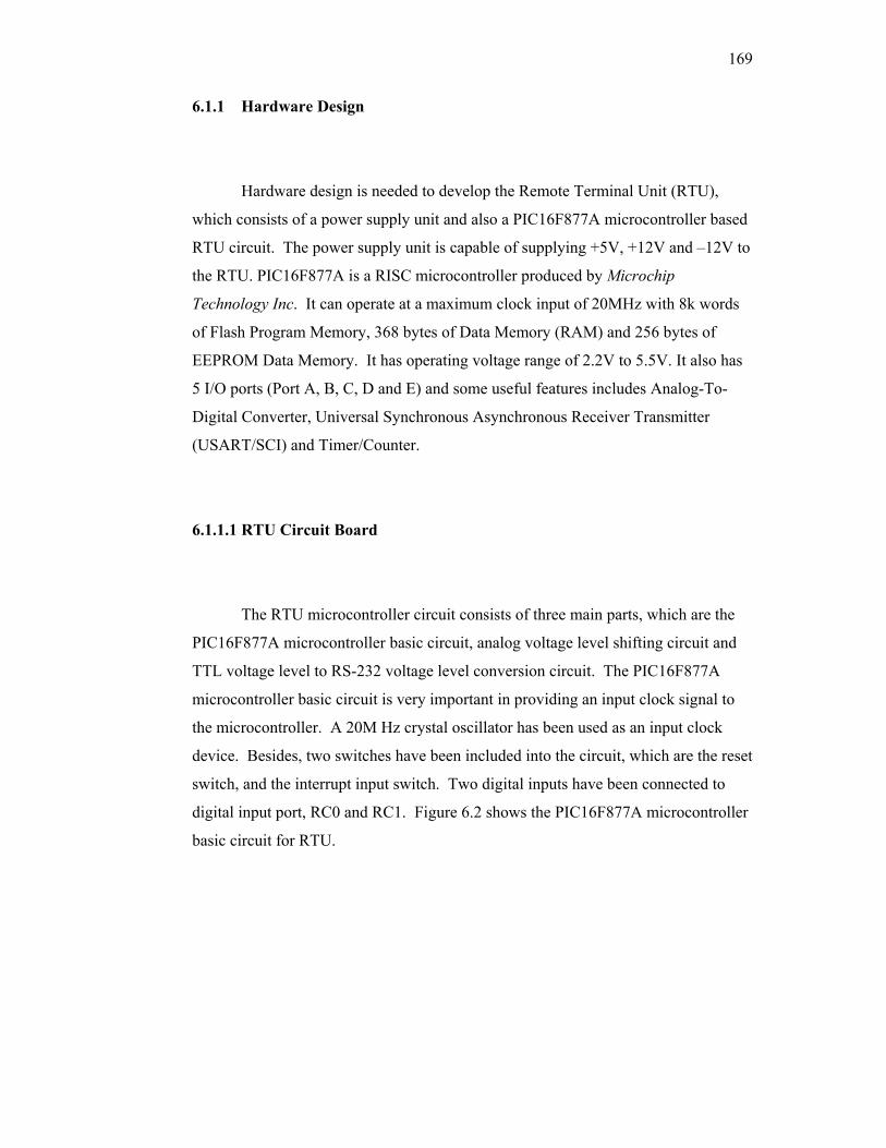
169
6.1.1 Hardware Design
Hardware design is needed to develop the Remote Terminal Unit (RTU),
which consists of a power supply unit and also a PIC16F877A microcontroller based
RTU circuit. The power supply unit is capable of supplying +5V, +12V and –12V to
the RTU. PIC16F877A is a RISC microcontroller produced by Microchip
Technology Inc. It can operate at a maximum clock input of 20MHz with 8k words
of Flash Program Memory, 368 bytes of Data Memory (RAM) and 256 bytes of
EEPROM Data Memory. It has operating voltage range of 2.2V to 5.5V. It also has
5 I/O ports (Port A, B, C, D and E) and some useful features includes Analog-To-
Digital Converter, Universal Synchronous Asynchronous Receiver Transmitter
(USART/SCI) and Timer/Counter.
6.1.1.1 RTU Circuit Board
The RTU microcontroller circuit consists of three main parts, which are the
PIC16F877A microcontroller basic circuit, analog voltage level shifting circuit and
TTL voltage level to RS-232 voltage level conversion circuit. The PIC16F877A
microcontroller basic circuit is very important in providing an input clock signal to
the microcontroller. A 20M Hz crystal oscillator has been used as an input clock
device. Besides, two switches have been included into the circuit, which are the reset
switch, and the interrupt input switch. Two digital inputs have been connected to
digital input port, RC0 and RC1. Figure 6.2 shows the PIC16F877A microcontroller
basic circuit for RTU.
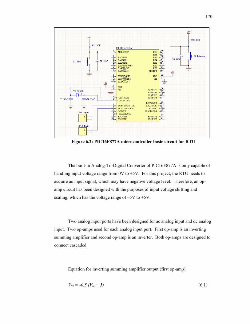
170
Figure 6.2: PIC16F877A microcontroller basic circuit for RTU
The built-in Analog-To-Digital Converter of PIC16F877A is only capable of
handling input voltage range from 0V to +5V. For this project, the RTU needs to
acquire ac input signal, which may have negative voltage level. Therefore, an op-
amp circuit has been designed with the purposes of input voltage shifting and
scaling, which has the voltage range of –5V to +5V.
Two analog input ports have been designed for ac analog input and dc analog
input. Two op-amps used for each analog input port. First op-amp is an inverting
summing amplifier and second op-amp is an inverter. Both op-amps are designed to
connect cascaded.
Equation for inverting summing amplifier output (first op-amp):
V01 = -0.5 (Vin + 5) (6.1)
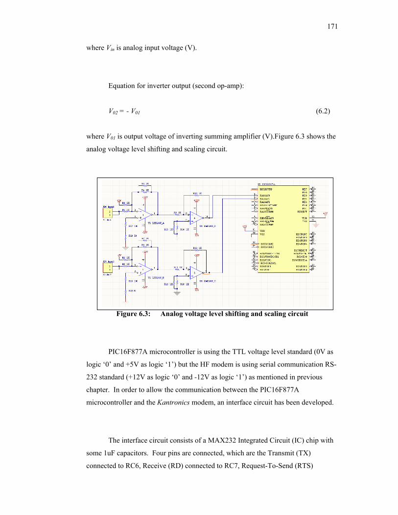
171
where Vin is analog input voltage (V).
Equation for inverter output (second op-amp):
V02 = - V01 (6.2)
where V01 is output voltage of inverting summing amplifier (V).Figure 6.3 shows the
analog voltage level shifting and scaling circuit.
Figure 6.3: Analog voltage level shifting and scaling circuit
PIC16F877A microcontroller is using the TTL voltage level standard (0V as
logic ‘0’ and +5V as logic ‘1’) but the HF modem is using serial communication RS-
232 standard (+12V as logic ‘0’ and -12V as logic ‘1’) as mentioned in previous
chapter. In order to allow the communication between the PIC16F877A
microcontroller and the Kantronics modem, an interface circuit has been developed.
The interface circuit consists of a MAX232 Integrated Circuit (IC) chip with
some 1uF capacitors. Four pins are connected, which are the Transmit (TX)
connected to RC6, Receive (RD) connected to RC7, Request-To-Send (RTS)
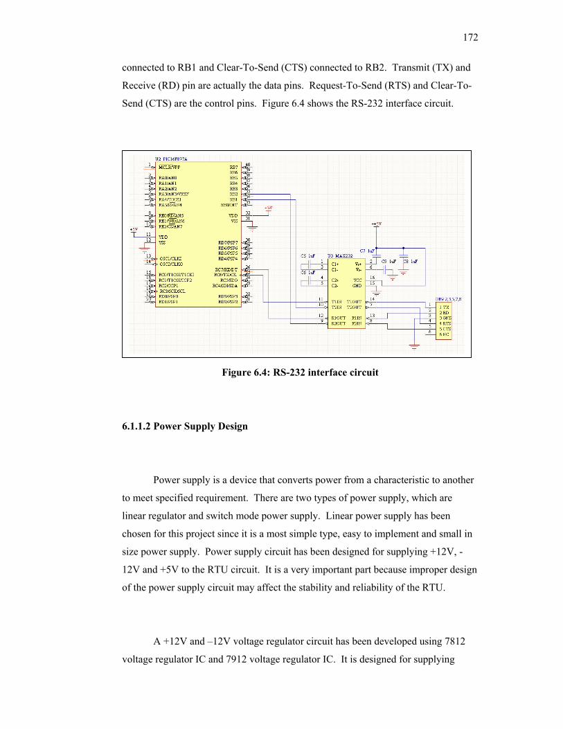
172
connected to RB1 and Clear-To-Send (CTS) connected to RB2. Transmit (TX) and
Receive (RD) pin are actually the data pins. Request-To-Send (RTS) and Clear-To-
Send (CTS) are the control pins. Figure 6.4 shows the RS-232 interface circuit.
:
Figure 6.4: RS-232 interface circuit
6.1.1.2 Power Supply Design
Power supply is a device that converts power from a characteristic to another
to meet specified requirement. There are two types of power supply, which are
linear regulator and switch mode power supply. Linear power supply has been
chosen for this project since it is a most simple type, easy to implement and small in
size power supply. Power supply circuit has been designed for supplying +12V, -
12V and +5V to the RTU circuit. It is a very important part because improper design
of the power supply circuit may affect the stability and reliability of the RTU.
A +12V and –12V voltage regulator circuit has been developed using 7812
voltage regulator IC and 7912 voltage regulator IC. It is designed for supplying
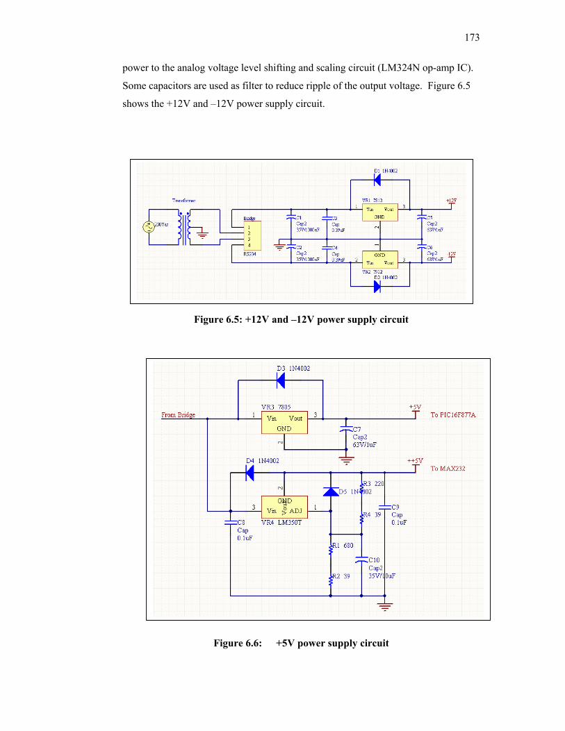
173
power to the analog voltage level shifting and scaling circuit (LM324N op-amp IC).
Some capacitors are used as filter to reduce ripple of the output voltage. Figure 6.5
shows the +12V and –12V power supply circuit.
Figure 6.5: +12V and –12V power supply circuit
Figure 6.6: +5V power supply circuit
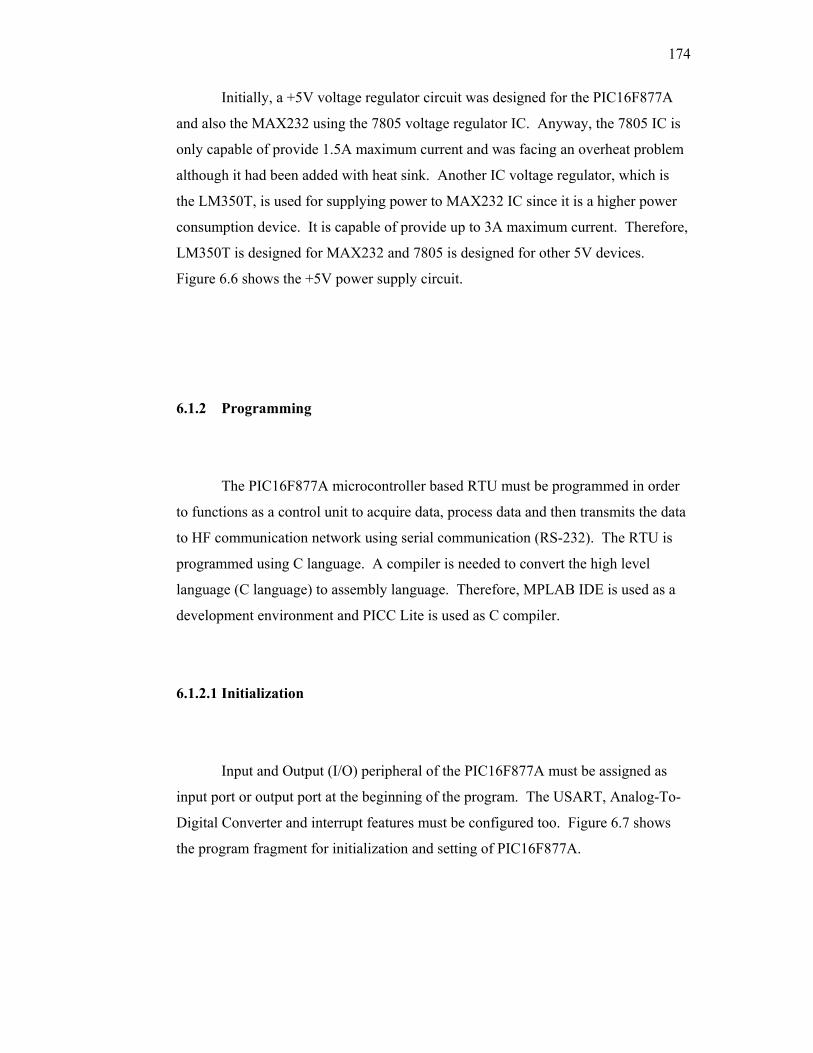
174
Initially, a +5V voltage regulator circuit was designed for the PIC16F877A
and also the MAX232 using the 7805 voltage regulator IC. Anyway, the 7805 IC is
only capable of provide 1.5A maximum current and was facing an overheat problem
although it had been added with heat sink. Another IC voltage regulator, which is
the LM350T, is used for supplying power to MAX232 IC since it is a higher power
consumption device. It is capable of provide up to 3A maximum current. Therefore,
LM350T is designed for MAX232 and 7805 is designed for other 5V devices.
Figure 6.6 shows the +5V power supply circuit.
6.1.2 Programming
The PIC16F877A microcontroller based RTU must be programmed in order
to functions as a control unit to acquire data, process data and then transmits the data
to HF communication network using serial communication (RS-232). The RTU is
programmed using C language. A compiler is needed to convert the high level
language (C language) to assembly language. Therefore, MPLAB IDE is used as a
development environment and PICC Lite is used as C compiler.
6.1.2.1 Initialization
Input and Output (I/O) peripheral of the PIC16F877A must be assigned as
input port or output port at the beginning of the program. The USART, Analog-To-
Digital Converter and interrupt features must be configured too. Figure 6.7 shows
the program fragment for initialization and setting of PIC16F877A.
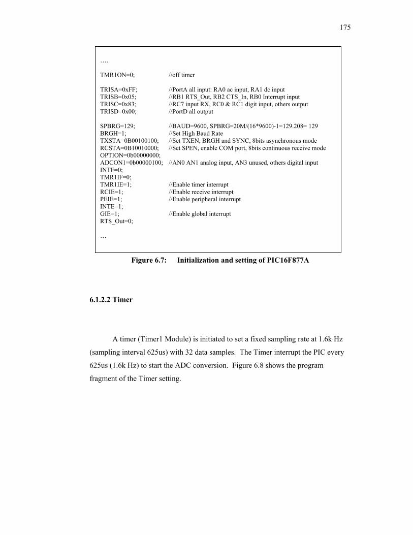
175
Figure 6.7: Initialization and setting of PIC16F877A
6.1.2.2 Timer
A timer (Timer1 Module) is initiated to set a fixed sampling rate at 1.6k Hz
(sampling interval 625us) with 32 data samples. The Timer interrupt the PIC every
625us (1.6k Hz) to start the ADC conversion. Figure 6.8 shows the program
fragment of the Timer setting.
…. TMR1ON=0; //off timer TRISA=0xFF; //PortA all input: RA0 ac input, RA1 dc input TRISB=0x05; //RB1 RTS_Out, RB2 CTS_In, RB0 Interrupt input TRISC=0x83; //RC7 input RX, RC0 & RC1 digit input, others output TRISD=0x00; //PortD all output SPBRG=129; //BAUD=9600, SPBRG=20M/(16*9600)-1=129.208= 129 BRGH=1; //Set High Baud Rate TXSTA=0B00100100; //Set TXEN, BRGH and SYNC, 8bits asynchronous mode RCSTA=0B10010000; //Set SPEN, enable COM port, 8bits continuous receive mode OPTION=0b00000000; ADCON1=0b00000100; //AN0 AN1 analog input, AN3 unused, others digital input INTF=0; TMR1IF=0; TMR1IE=1; //Enable timer interrupt RCIE=1; //Enable receive interrupt PEIE=1; //Enable peripheral interrupt INTE=1; GIE=1; //Enable global interrupt RTS_Out=0; …
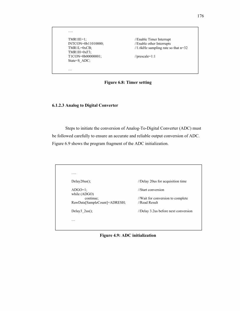
176
Figure 6.8: Timer setting
6.1.2.3 Analog to Digital Converter
Steps to initiate the conversion of Analog-To-Digital Converter (ADC) must
be followed carefully to ensure an accurate and reliable output conversion of ADC.
Figure 6.9 shows the program fragment of the ADC initialization.
Figure 4.9: ADC initialization
…. TMR1IE=1; //Enable Timer Interrupt INTCON=0b11010000; //Enable other Interrupts TMR1L=0xCB; //1.6kHz sampling rate so that n=32 TMR1H=0xF3; T1CON=0b00000001; //prescale=1:1 State=S_ADC; …
…. Delay20us(); //Delay 20us for acquisition time ADGO=1; //Start conversion while (ADGO) continue; //Wait for conversion to complete RawData[SampleCount]=ADRESH; //Read Result Delay3_2us(); //Delay 3.2us before next conversion …
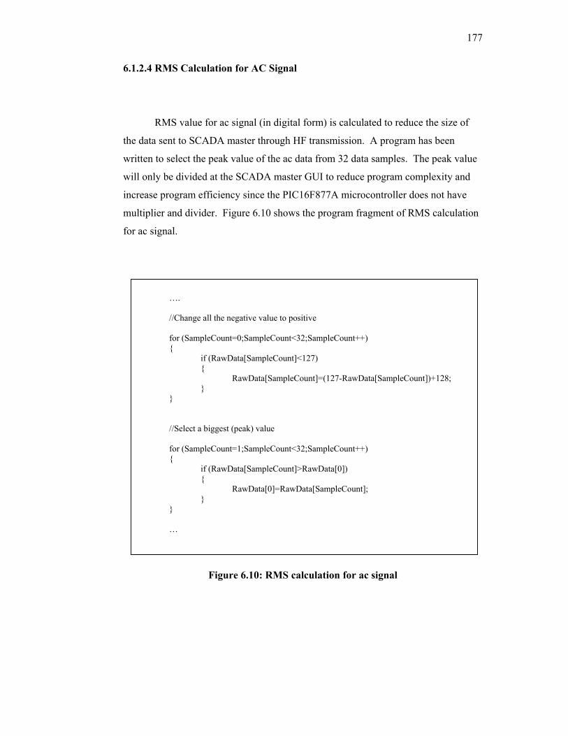
177
6.1.2.4 RMS Calculation for AC Signal
RMS value for ac signal (in digital form) is calculated to reduce the size of
the data sent to SCADA master through HF transmission. A program has been
written to select the peak value of the ac data from 32 data samples. The peak value
will only be divided at the SCADA master GUI to reduce program complexity and
increase program efficiency since the PIC16F877A microcontroller does not have
multiplier and divider. Figure 6.10 shows the program fragment of RMS calculation
for ac signal.
Figure 6.10: RMS calculation for ac signal
…. //Change all the negative value to positive for (SampleCount=0;SampleCount<32;SampleCount++) { if (RawData[SampleCount]<127) { RawData[SampleCount]=(127-RawData[SampleCount])+128; } } //Select a biggest (peak) value for (SampleCount=1;SampleCount<32;SampleCount++) { if (RawData[SampleCount]>RawData[0]) { RawData[0]=RawData[SampleCount]; } } …
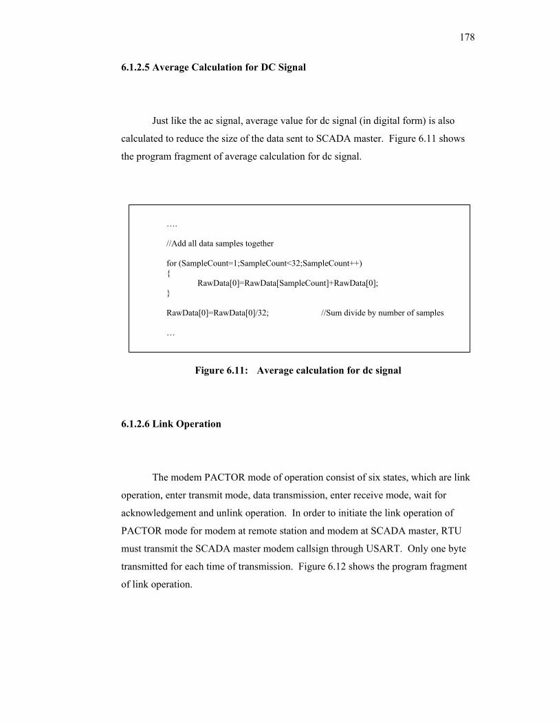
178
6.1.2.5 Average Calculation for DC Signal
Just like the ac signal, average value for dc signal (in digital form) is also
calculated to reduce the size of the data sent to SCADA master. Figure 6.11 shows
the program fragment of average calculation for dc signal.
Figure 6.11: Average calculation for dc signal
6.1.2.6 Link Operation
The modem PACTOR mode of operation consist of six states, which are link
operation, enter transmit mode, data transmission, enter receive mode, wait for
acknowledgement and unlink operation. In order to initiate the link operation of
PACTOR mode for modem at remote station and modem at SCADA master, RTU
must transmit the SCADA master modem callsign through USART. Only one byte
transmitted for each time of transmission. Figure 6.12 shows the program fragment
of link operation.
…. //Add all data samples together
for (SampleCount=1;SampleCount<32;SampleCount++) { RawData[0]=RawData[SampleCount]+RawData[0]; } RawData[0]=RawData[0]/32; //Sum divide by number of samples …
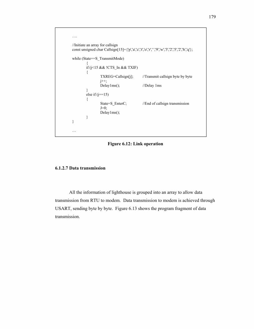
179
Figure 6.12: Link operation
6.1.2.7 Data transmission
All the information of lighthouse is grouped into an array to allow data
transmission from RTU to modem. Data transmission to modem is achieved through
USART, sending byte by byte. Figure 6.13 shows the program fragment of data
transmission.
…. //Initiate an array for callsign const unsigned char Callsign[15]={'p','a','c','t','o','r',' ','9','w','3','2','5','2','h','q'}; while (State==S_TransmitMode) { if (j<15 && !CTS_In && TXIF) { TXREG=Callsign[j]; //Transmit callsign byte by byte j++; Delay1ms(); //Delay 1ms } else if (j==15) {
State=S_EnterC; //End of callsign transmission J=0; Delay1ms();
} }
…
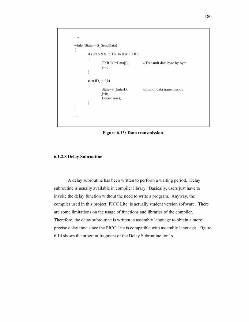
180
Figure 6.13: Data transmission
6.1.2.8 Delay Subroutine
A delay subroutine has been written to perform a waiting period. Delay
subroutine is usually available in compiler library. Basically, users just have to
invoke the delay function without the need to write a program. Anyway, the
compiler used in this project, PICC Lite, is actually student version software. There
are some limitations on the usage of functions and libraries of the compiler.
Therefore, the delay subroutine is written in assembly language to obtain a more
precise delay time since the PICC Lite is compatible with assembly language. Figure
6.14 shows the program fragment of the Delay Subroutine for 1s.
…. while (State==S_SendData) { if (j<16 && !CTS_In && TXIF) { TXREG=Data[j]; //Transmit data byte by byte j++; } else if (j==16) { State=S_EnterD; //End of data transmission j=0; Delay1ms(); } } …
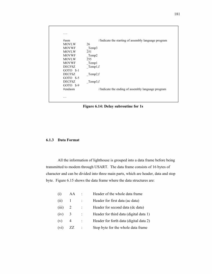
181
Figure 6.14: Delay subroutine for 1s
6.1.3 Data Format
All the information of lighthouse is grouped into a data frame before being
transmitted to modem through USART. The data frame consists of 16 bytes of
character and can be divided into three main parts, which are header, data and stop
byte. Figure 6.15 shows the data frame where the data structures are:
(i) AA : Header of the whole data frame
(ii) 1 : Header for first data (ac data)
(iii) 2 : Header for second data (dc data)
(iv) 3 : Header for third data (digital data 1)
(v) 4 : Header for forth data (digital data 2)
(vi) ZZ : Stop byte for the whole data frame
…. #asm //Indicate the starting of assembly language program MOVLW 26 MOVWF _Temp3 MOVLW 251 MOVWF _Temp2 MOVLW 255 MOVWF _Temp1 DECFSZ _Temp1,f GOTO $-1 DECFSZ _Temp2,f GOTO $-5 DECFSZ _Temp3,f GOTO $-9 #endasm //Indicate the ending of assembly language program …
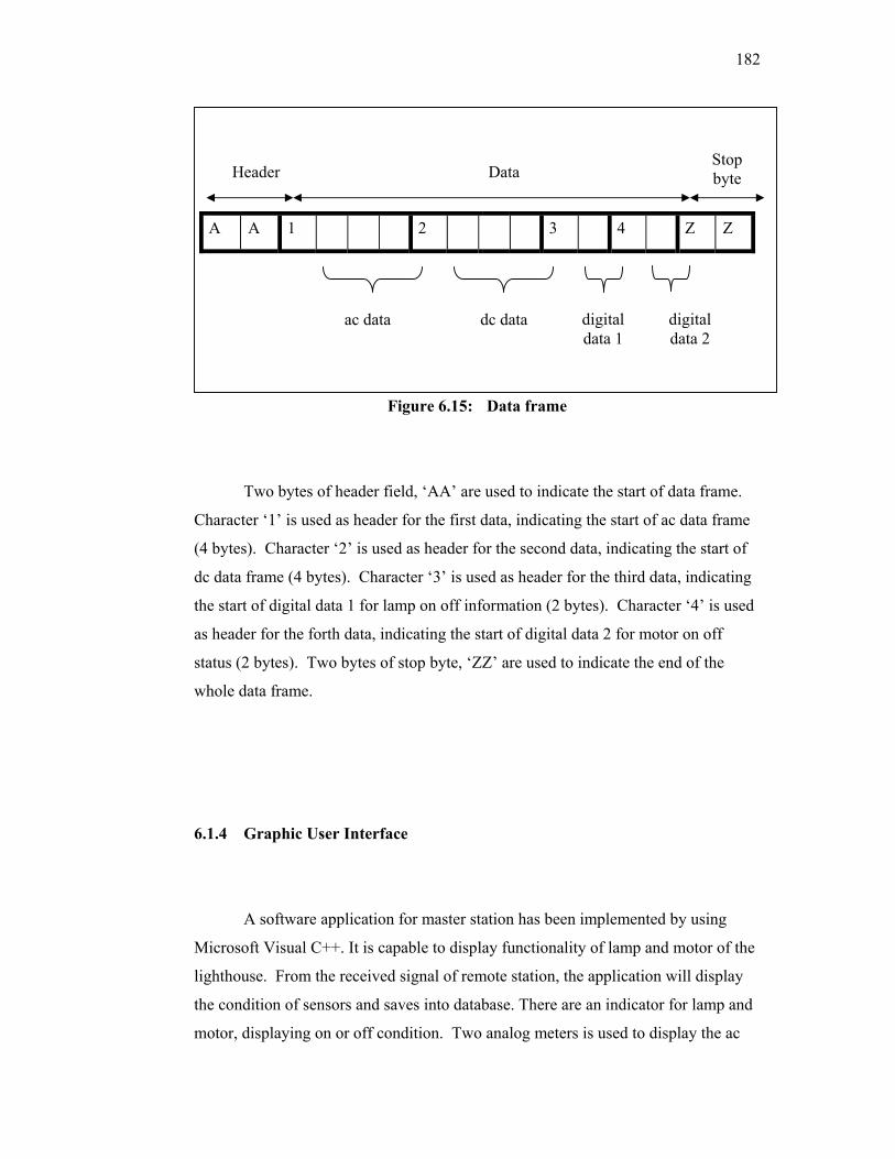
182
A A 1 2 3 4 Z Z
Figure 6.15: Data frame
Two bytes of header field, ‘AA’ are used to indicate the start of data frame.
Character ‘1’ is used as header for the first data, indicating the start of ac data frame
(4 bytes). Character ‘2’ is used as header for the second data, indicating the start of
dc data frame (4 bytes). Character ‘3’ is used as header for the third data, indicating
the start of digital data 1 for lamp on off information (2 bytes). Character ‘4’ is used
as header for the forth data, indicating the start of digital data 2 for motor on off
status (2 bytes). Two bytes of stop byte, ‘ZZ’ are used to indicate the end of the
whole data frame.
6.1.4 Graphic User Interface
A software application for master station has been implemented by using
Microsoft Visual C++. It is capable to display functionality of lamp and motor of the
lighthouse. From the received signal of remote station, the application will display
the condition of sensors and saves into database. There are an indicator for lamp and
motor, displaying on or off condition. Two analog meters is used to display the ac
ac data dc data digital data 1
digital data 2
Header Data Stop byte

183
and dc voltage level. There are also date and time indicator on the GUI. Besides, a
command centre has been implemented to display the exact data being transmitted or
received through the serial communication. This command indicator is used for
troubleshooting purpose.
Figure 6.16: Software applications for light house telemetry system
The ‘data from Remote Terminal Unit (RTU)’ column in the GUI is used to
show the communication between remote and master station. ‘<PACTOR
STANBY>’ indicates the master station is in waiting state for data receiving from
remote station. ‘<LINKED TO 9W3252TT>’ indicates the link operation between
remote and master station is successful. The ‘AA122121933141ZZ’ is the 16 bytes
data frame received by master station. ‘DONE’ is the acknowledgement being sent
by master station to the remote station that the data has been successfully received.
‘<PACTOR STANBY>’ indicates the unlink operation is done. It also indicates that
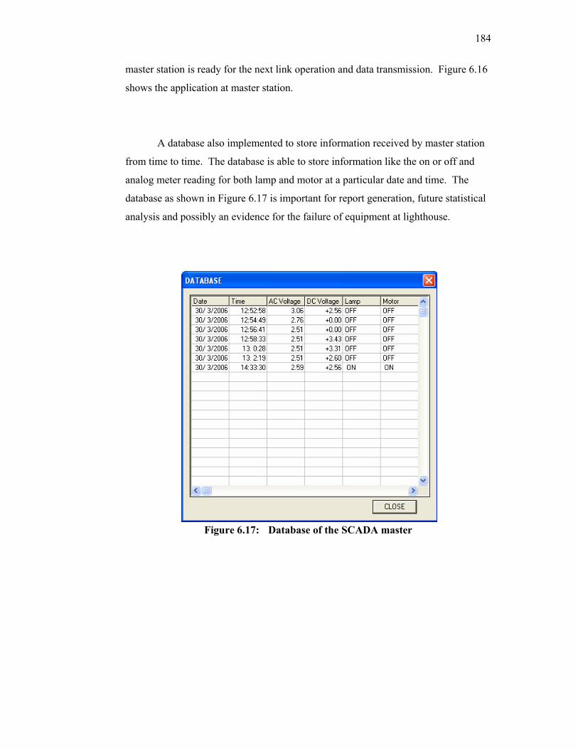
184
master station is ready for the next link operation and data transmission. Figure 6.16
shows the application at master station.
A database also implemented to store information received by master station
from time to time. The database is able to store information like the on or off and
analog meter reading for both lamp and motor at a particular date and time. The
database as shown in Figure 6.17 is important for report generation, future statistical
analysis and possibly an evidence for the failure of equipment at lighthouse.
Figure 6.17: Database of the SCADA master
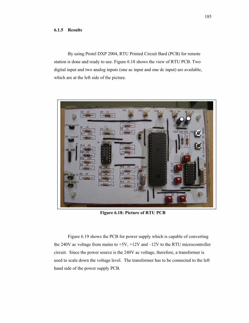
185
6.1.5 Results
By using Protel DXP 2004, RTU Printed Circuit Bard (PCB) for remote
station is done and ready to use. Figure 6.18 shows the view of RTU PCB. Two
digital input and two analog inputs (one ac input and one dc input) are available,
which are at the left side of the picture.
Figure 6.18: Picture of RTU PCB
Figure 6.19 shows the PCB for power supply which is capable of converting
the 240V ac voltage from mains to +5V, +12V and –12V to the RTU microcontroller
circuit. Since the power source is the 240V ac voltage, therefore, a transformer is
used to scale down the voltage level. The transformer has to be connected to the left
hand side of the power supply PCB.
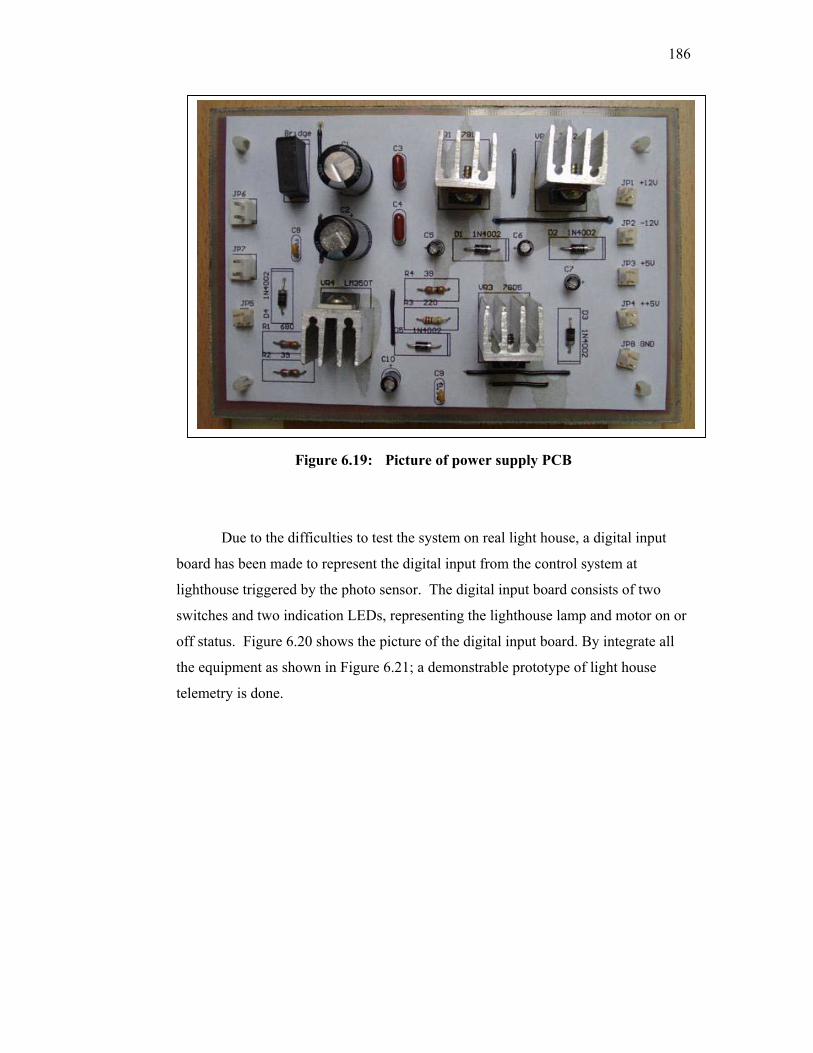
186
Figure 6.19: Picture of power supply PCB
Due to the difficulties to test the system on real light house, a digital input
board has been made to represent the digital input from the control system at
lighthouse triggered by the photo sensor. The digital input board consists of two
switches and two indication LEDs, representing the lighthouse lamp and motor on or
off status. Figure 6.20 shows the picture of the digital input board. By integrate all
the equipment as shown in Figure 6.21; a demonstrable prototype of light house
telemetry is done.
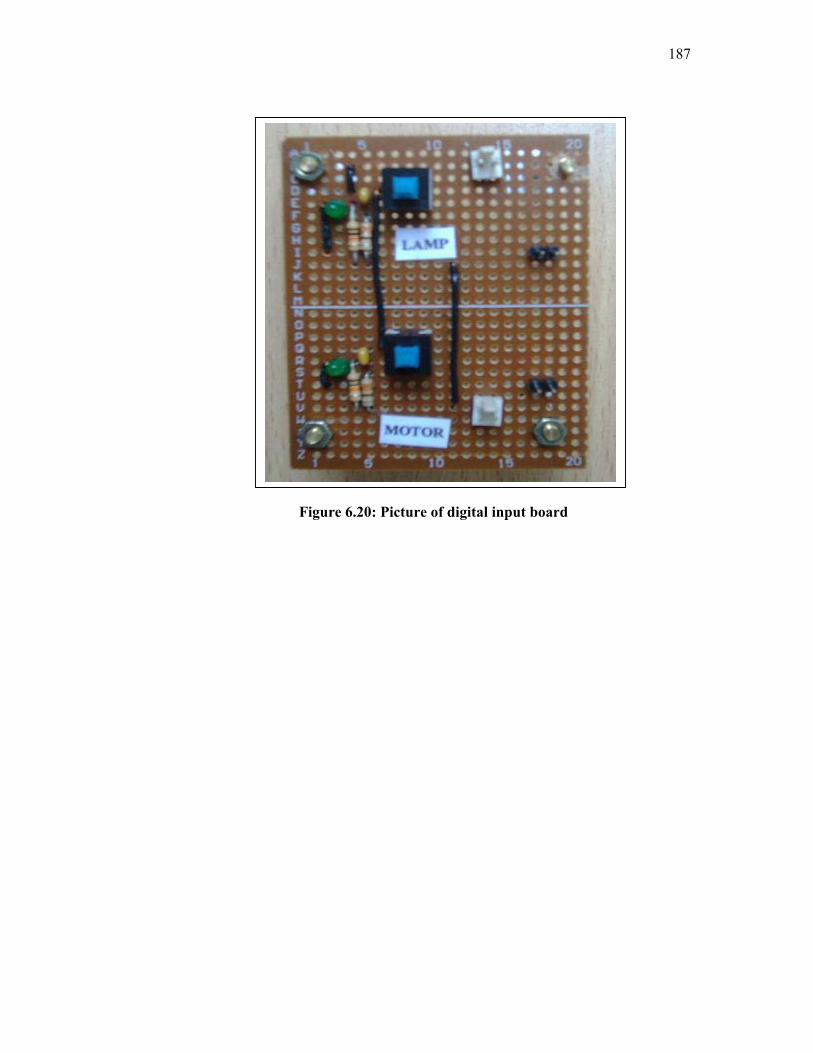
187
Figure 6.20: Picture of digital input board
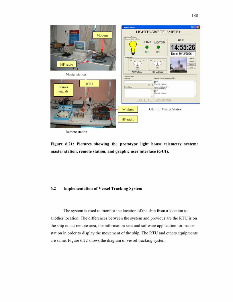
188
Figure 6.21: Pictures showing the prototype light house telemetry system:
master station, remote station, and graphic user interface (GUI).
6.2 Implementation of Vessel Tracking System
The system is used to monitor the location of the ship from a location to
another location. The differences between the system and previous are the RTU is on
the ship not at remote area, the information sent and software application for master
station in order to display the movement of the ship. The RTU and others equipments
are same. Figure 6.22 shows the diagram of vessel tracking system.
Remote station
Master station
GUI for Master Station Modem
HF radio
Modem
HF radio
RTU Sensor signals
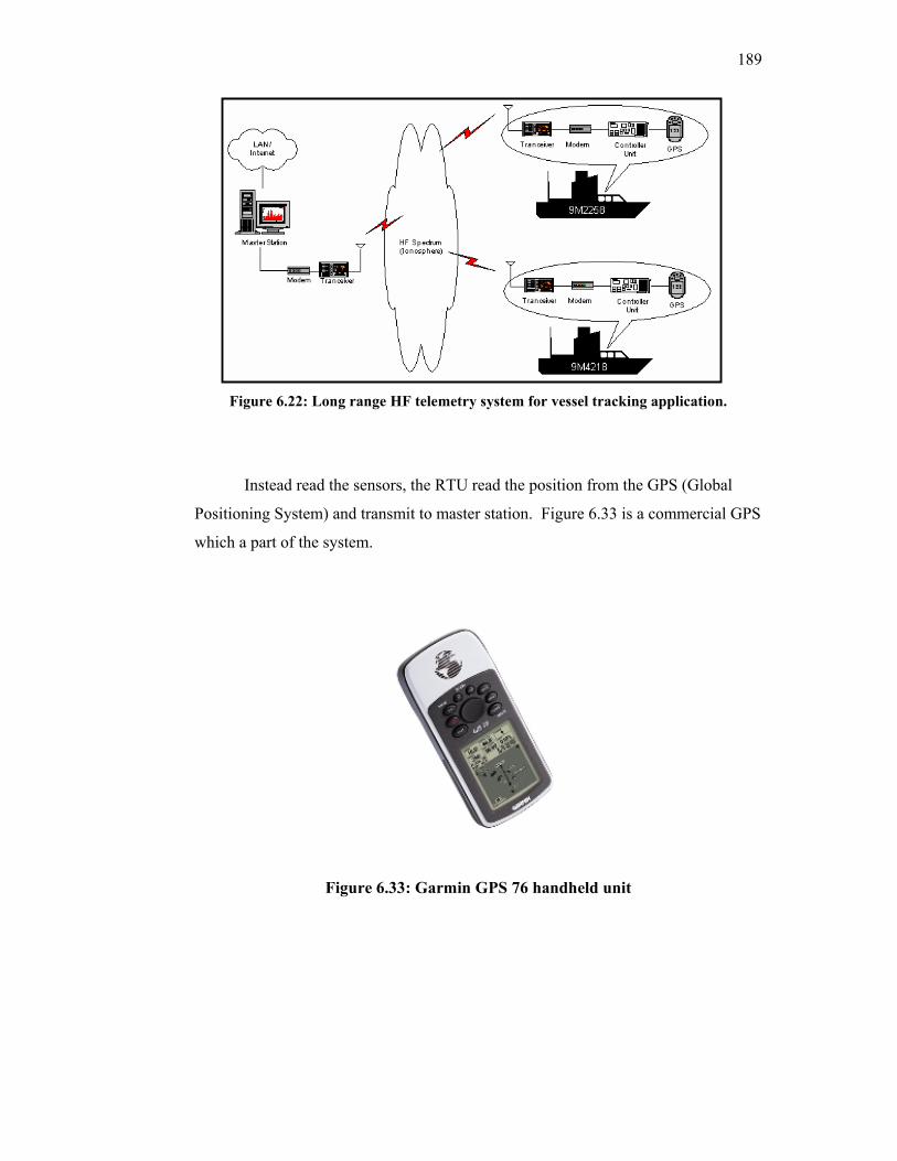
189
Figure 6.22: Long range HF telemetry system for vessel tracking application.
Instead read the sensors, the RTU read the position from the GPS (Global
Positioning System) and transmit to master station. Figure 6.33 is a commercial GPS
which a part of the system.
Figure 6.33: Garmin GPS 76 handheld unit
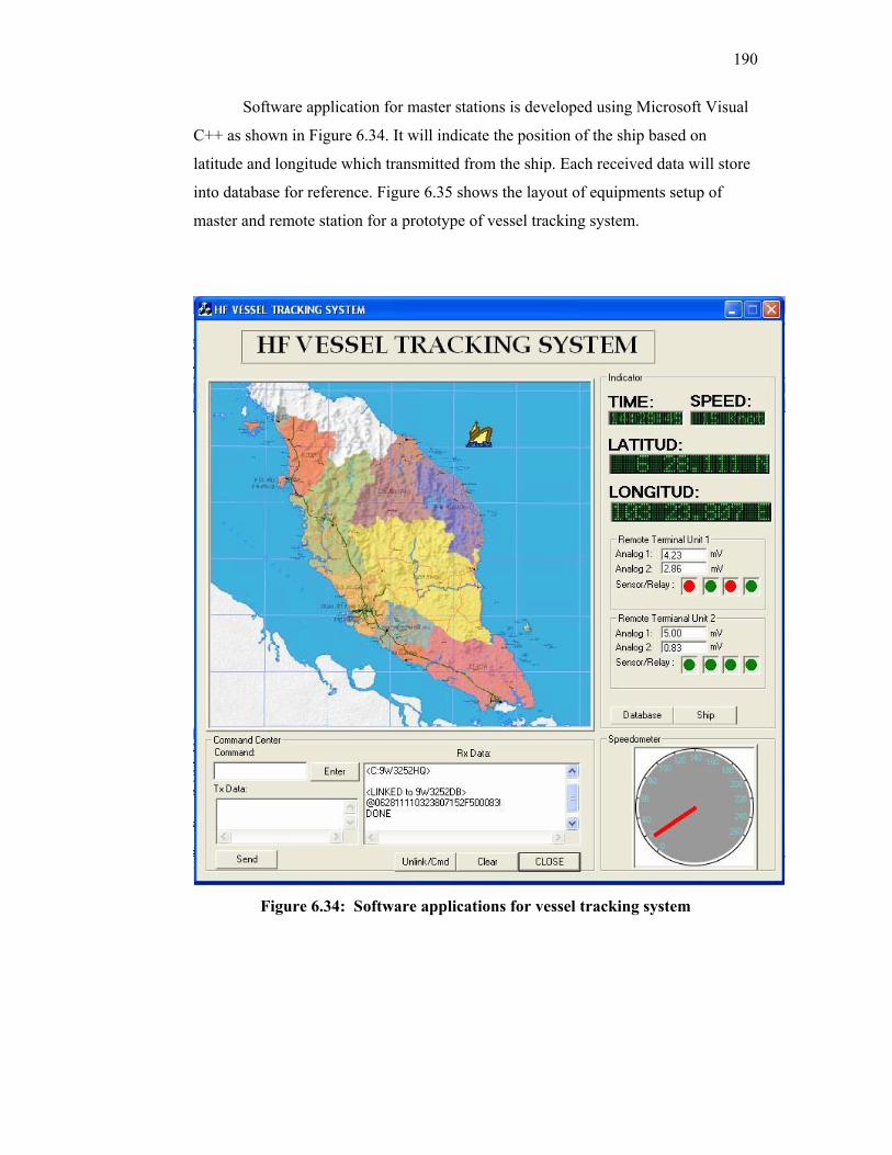
190
Software application for master stations is developed using Microsoft Visual
C++ as shown in Figure 6.34. It will indicate the position of the ship based on
latitude and longitude which transmitted from the ship. Each received data will store
into database for reference. Figure 6.35 shows the layout of equipments setup of
master and remote station for a prototype of vessel tracking system.
Figure 6.34: Software applications for vessel tracking system
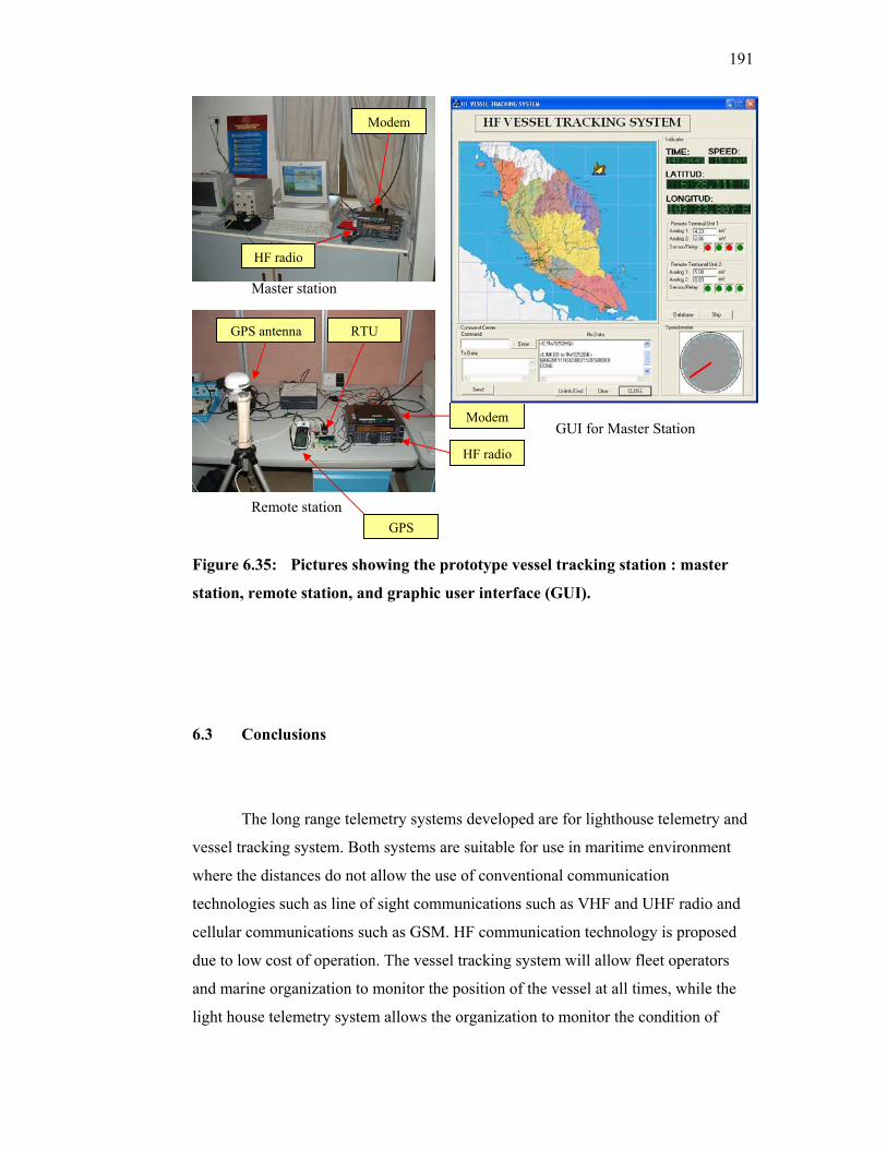
191
Figure 6.35: Pictures showing the prototype vessel tracking station : master
station, remote station, and graphic user interface (GUI).
6.3 Conclusions
The long range telemetry systems developed are for lighthouse telemetry and
vessel tracking system. Both systems are suitable for use in maritime environment
where the distances do not allow the use of conventional communication
technologies such as line of sight communications such as VHF and UHF radio and
cellular communications such as GSM. HF communication technology is proposed
due to low cost of operation. The vessel tracking system will allow fleet operators
and marine organization to monitor the position of the vessel at all times, while the
light house telemetry system allows the organization to monitor the condition of
Remote station
Master station
GUI for Master Station
GPS
RTU
Modem
GPS antenna
HF radio
Modem
HF radio

192
equipment to ensure navigation safety. The present systems are already implemented
and tested in the lab
CHAPTER 7
CONCLUSIONS
HF communications is no longer limited to voice and telegraphy but today has
included applications such as short messaging, file transfer, email and telemetry. Long
distance communication over the HF spectrum is achieved by the refraction of radio
waves on the ionosphere. The outcome of this research has produced a prototype HF data
transmission system that is capable to transmit images. Additional features of the system
include short messaging, telemetry and file transfer, and cryptographic features such as
authentication, key distribution and confidentiality. The proposed system is useful any
users that operates over large expanse of land and water where the cost of setting up and
operating a communication infrastructure is not economical. Possible end user for this
product includes the military, law enforcement, deep sea fishing, oil and gas and amateur
radio. The project has achieved all of the objectives with the inclusion of telemetry
applications.
Some preliminary work was done in the development of robust high speed
modem based on the Texas Instrument’s TMS320C5416 DSP processor. Due the effect
of multipath fading and interference in the HF spectrum, it was concluded that further
research should be continued in this area. Future work will also include the inclusion of

194
email function as part of the HF data communication system. With this features, users are
able to communicate with existing email services eventhough they are not accessible by
the conventional communication infrastructure such as the PSTN (Public Switched
Telephone Network) and the cellular telephone network.
194
REFERENCES
Abdullah, M.A., Husni, E.M.S., and Hassan, S.I. (2003). “Investigation of a rural
telecommunication System using VSAT Technology in Malaysia”. 9th Asia Pacific
Conference on Communications, 2003(APCC). 21-24 September 2003 Penang.
ACP 127(G) (1988). “Communication Instructions Tape Relay Procedures”. Allied
Communication Publication.
ARRL (2002). “The Arrl Handbook for Radio Ameteurs 2002”. 79th edition. USA: The
American Radio Relay League, Inc
Barr, D (2004)., “Supervisory Control and Data Acquisition Systems”, NCS TIB 04-1, National Communications System, October 2004.
Beker, H., and Piper, F. (1982). “Cipher Systems: Protection of Communications”.
Northwood Publications, London.
Beker, H., and Piper, F. (1985). “Secure Speech Communications”. Academic Press,
London.
Blonstein, S.; Katorgi, M.; (2003), “eXpressDSP for DUMMIES”, Wiley Publishing Inc,
1st edition 2003
Boyarinov, I.; Martin, I.; Honary, B.; (2000), “High-speed decoding of extended Golay
code”, Communications, IEEE Proceedings-, Volume: 147, Issue: 6, Dec. 2000
Brakemeier, A.; Lindner, J.; (1988), “Single-tone HF data transmission with 2.4 kbps and
4.8 kbps”, HF Radio Systems and Techniques, 1988, Fourth International
Conference, 1988
Carr, J.J.; (2001), “Practical Antenna Handbook”, McGraw-Hill 4th Edition 2001
195
Clark, P.D.J.; Horley, N.; Darnell, M.; Honary, B.; (1993), “DSP modem/codec
implementation for long-range radio applications”, DSP Applications in
Communication Systems, IEE Colloquium, 1993
Cook, S.C.; Giles, T.C.; Vyden, B.; Gill, M.C.; (1993), “Error-control options for
parallel-tone HF modems”, Military Communications Conference, 1993. MILCOM
'93. Conference record. 'Communications on the Move’, IEEE, Volume: 3, 11-14
Oct. 1993
Couch L.W. II.; (1997), “Digital and Analog Communication Systems”, Prentice Hall
International Inc 5th edition 1997
Cruiseemail (2004). “CruiseEmail.com”. http://www.cruiseemail.com/
Crypto AG (2004). “For communication & information security”. http://www.crypto.ch
Diffie, W and Hellman, M.E. (1997). "New directions in cryptography". IEEE Trans.
Info. Theory. IT-22, pp. 644 - 654.
Ekdahl, P., and Johansson, T. (2001). “SNOW- a new stream cipher”. Lund University
Sweden.
Federal Standard 1037C, “Federal Standard 1037C: Glosary of Telecommunications
Terms”. http://glossary .its.bldrdoc.gov/fs-1037/fs-1037c.htm.
Golic, J., and Mihaljevic, M. (1990). “Minimal Linear Equivalent Analysis of a Variable-
Memory Binary Sequence Generator”. IEEE Transactions on Information Theory. 36(1):
190-192.
Golomb, S. (1967). “Shift Register Sequences”. Holden Day.
Goodman J.M.; (1992), “HF Communications Science and Technology”, Van Nostrand
Reinhold 1992
196
Harris Corporation (2002). “RF 3700H Harris Universal Image Transmission Software”.
RF Communication Division, Harris Corporation.
Harris Corporation; (1996), “Radio Communications in the Digital Age. Volume I HF
Technology”, Harris Corporation 1st edition 1996
Hawkes, P., and Rose, G. (2002). “Guess-and-Determine Attacks on SNOW”. Qualcomm
Australia.
Hoult, N.S.; Whiffen, J.R.; Tooby, M.H.; Arthur, P.C.; (2000), “16 kbps modems for the
HF NVIS channel”, HF Radio Systems and Techniques, 2000. Eighth International
Conference on (IEE Conf. Publ. No. 474), 2000
Johnson, R. (1992). “Elementary Statistics”. PWS-Kent.
Johston, J. (1999). “Southwinds: Local news for Southern Sailors”.
http://www.southwindssailling.com/articles/9905/indek9905.html
Jorgenson, M.B.; Johnson, R.W.; Moreland, K.W.; (2001), “An examination of HF
modems platform architectures,” Military Communications Conference, 2001,
MILCOM 2001, Communications for Network-Centric Operations: Creating the
Information Force. IEEE, Volume: 1, 28-31 Oct. 2001
Jorgenson, M.B.; Johnson, R.W.; Moreland, K.W.; Bova, W.E.; Jones, P.F.; (2000),
“Meeting military requirements for increased data rates at HF”, MILCOM 2000.
21st Century Military Communications Conference Proceedings, Volume: 2, 2000
Kantronics Co. (1998). “KAM ’98 Multi-Mode HF/VHF Digital Controller User’s
Guide”. Kantronics Co.
197
Kasser, J.E.; (1991), “Applied digital communications via HF radio”, HF Radio Systems
and Techniques, 1991, Fifth International Conference, 1991
Kenwood Corp. (1998). “HF Transceiver TS-570D Instruction Manual”. Kenwood Corp.
Kotlowski, A.; Brakemeier, A.; (2000), “Shortwave software modem, 14400 bps in 3
kHz”, HF Radio Systems and Techniques, 2000, Eighth International Conference
on (IEE Conf. Publ. No. 474), 2000 pp 311 –315
Kotsakis, E. (2004). “Secure Information Exchange”. Electronic Reporting Systems
(ERS). https://quickcheckinc.com
Lail, B.M. (2002). “Broadband Network & Device Security”. The McGraw-Hill
Companies.
Massey, J.L. (1969). “Shift Register Synthesis and BCH Coding Decoding”. IEEE Trans
on Information Theory. 15, pp 122-127.
Menezes, A., Oorschot, V., and Vanstone, S. (1996). “Handbook of Applied
Cryptography”, CRC Press.
Mils (2004). “The secret of unconditional security”. http://www.mils.com
MIL-STD-188-141B (1999). “Interoperability and Performance Standards for Medium
and High Frequency Radio System”. U.S Department of Defense, March 1999.
Mohamad Kamal, A.R. (2005). “Short-course on wireless communication system”.
Universiti Teknologi Malaysia.
National Institute of Standards and Technology (NIST) (2001). “Advance Encryption
Standard (AES)”. Federal Information Processing Standards Publication 197.
198
Nichols, R.K., and Lekkas, P.C. (2002). “Wireless Security: Models, Threats and
Solutions”. The McGraw-Hill Companies.
Nilsson, J.E.M.; Giles, T.C.; (1997), “Wideband multi-carrier transmission for military
HF communication”, MILCOM 97 Proceedings, Volume: 2, 1997 pp1046 -1051
vol.2.
NTIA-ITS (1998). “High Frequency Radio Automatic Link Establishment (ALE)
Application Handbook”. U.S. National Telecommunications and Information
Administration (NTIA), U.S. Inst. For Telecommunication Sciences (ITS), September
1998.
Nurhashimah Saad (2004), “Performance Analysis of Differential Phase Modulation for
HF Communication”, Master Thesis Universiti Technology of Malaysia (2004)
Oppenheim, A.V., Schafer, R.W.; (1999), “Discrete-Time Signal Processing”, Prentice
Hall Signal Processing Series 2nd edition 1999
Pactor (2004). “Pactor, your solution for shortwave radio communications”.
http://www.scs-ptc.com
Pawliw, B. (2001). “Block Cipher”.
http://searchsecurity.techtarget.com/sDefinition/0,,sid14_gci213593,00.html
Press, W., and Teukolsky, S. (1992). “Numerical Recipes in C”. Cambridge University
Press, London.
Quirke, J. (2004). “Security in the GSM system”. AusMobile.
Reed, D.G.; (2001), “The ARRL Handbook for Radio Amateurs”, The National
Association for Amateur Radio 79th edition 2001
199
Reidsradiodata (2004). “HF Radio Communication network”.
http://www.reidsradiodata.com.au/
Rose, G. (2000). “SOBER: A Stream Cipher based on Linear Feedback over GF (28)”.
QUALCOMM Australia.
SailMail (2004). “Sailmail : Email Services for Yachts via Marine HF SSB Radio”.
http://www.sailmail.com/
Scalsky, S.; Chace, M.; (1997), “Digital Signal FAQ”, in http://www.qsl.net/py1vhf/
swmodes.txt, Copyright (C) 1995,1996,1997 by Stan Scalsky, Copyright (C)
1995,1996,1997 by Mike Chace
Schneier, B. (1996). “Applied Cryptography”. Second Edition. John Wiley & Sons, Inc.
Siegenthaler, T. (1984). “Correlation-immunity of nonlinear combining functions for
Cryptographic applications”. IEEE Transactions on Information Theory. 30, 776–780.
Sklar B.; (2001), “Digital Communications Fundamentals and Application”, Prentice Hall
Inc 2nd edition 2001
Soyer, L. (2001). “HF Messenger/spl trade/: European trials and R&D efforts”. Military
Communications Conference. (MILCOM 2001). Blagnac.
Stalings W.; (2000), “Data and Computer Communications”, Prentice Hall Internal
Editions 6th edition, 2000
Stallings, W. (2003). “Cryptography and Network Security”. Prentice Hall.
Thomas, S., and Anthony, D. (2002). “The W7 Stream Cipher Algorithm”. University of
Waterloo.
200
Trinder, S.E.; Gillespie, A.F.R.; (2001), “Optimisation of the STANAG 5066 ARQ
protocol to support high data rate HF communications”, Military Communications
Conference, 2001. MILCOM 2001. Communications for Network-Centric
Operations: Creating the Information Force. IEEE , Volume: 1 , 2001 pp 482 –486
Tuan Sabri, T.M. (1995). “Analysis & Design of Stream Cipher Encryption Algorithms”,
Universiti Teknologi Malaysia, Skudai, Johor, Malaysia. Thesis Master.
Willink, T.J.; Davies, N.C.; Clarke, J.; Jorgenson, M.B.; (1996), “Validation of HF
channel simulators”, Frequency Selection and Management Techniques for HF
Communications, IEE Colloquium, 7-8 Feb 1996
Winlink (2000). “Enhanced digital messaging for amateur radio”. http://winlink.org/
“Texas Instruments Technology for Innovators, DSP Selection Guide”,
http://www.ti.dspvillage.com
“TMS320VC5416 Technical Reference”, Spectrum Digital Inc, Copyright © 2002
Australian Space Weather Agency, “IPS Radio and Space Services”, in
http://www.ips.gov.au
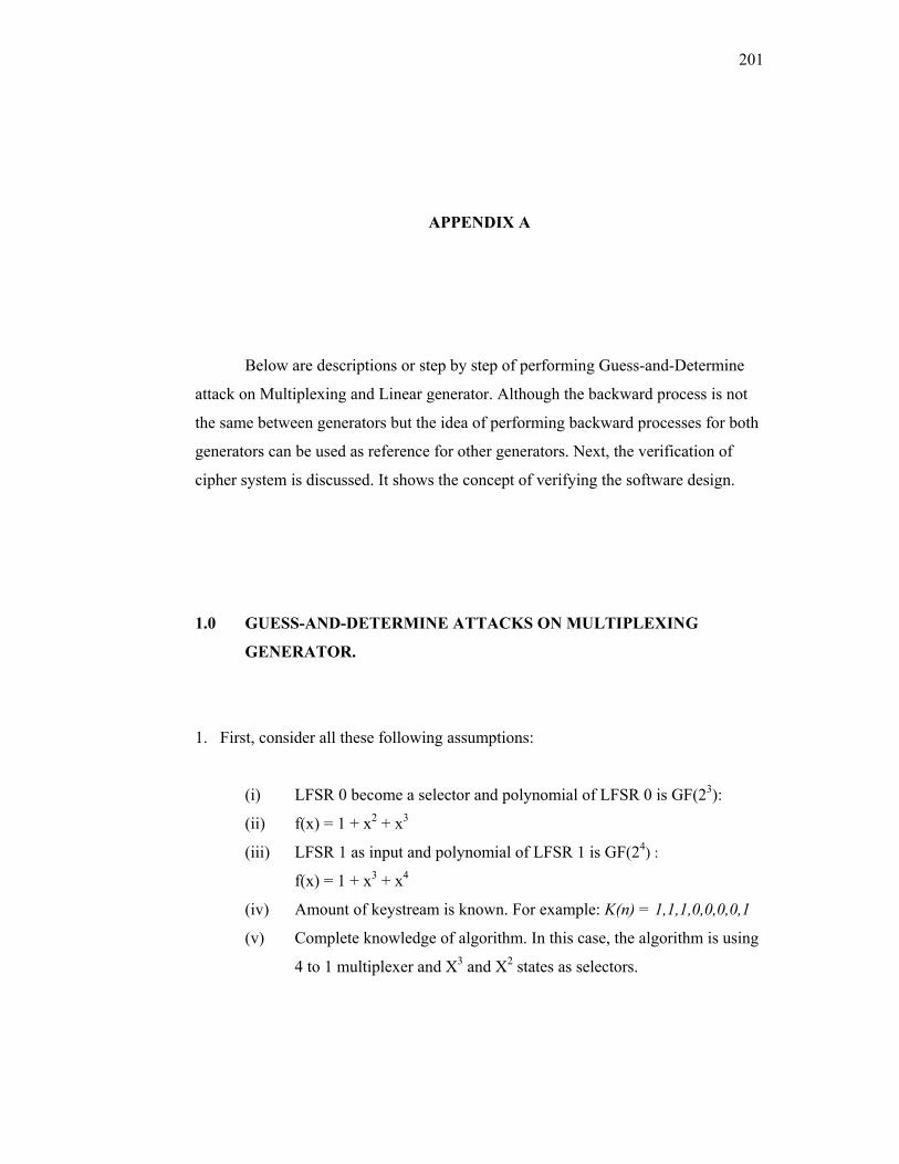
201
APPENDIX A
Below are descriptions or step by step of performing Guess-and-Determine
attack on Multiplexing and Linear generator. Although the backward process is not
the same between generators but the idea of performing backward processes for both
generators can be used as reference for other generators. Next, the verification of
cipher system is discussed. It shows the concept of verifying the software design.
1.0 GUESS-AND-DETERMINE ATTACKS ON MULTIPLEXING
GENERATOR.
1. First, consider all these following assumptions:
(i) LFSR 0 become a selector and polynomial of LFSR 0 is GF(23):
(ii) f(x) = 1 + x2 + x3
(iii) LFSR 1 as input and polynomial of LFSR 1 is GF(24) :
f(x) = 1 + x3 + x4
(iv) Amount of keystream is known. For example: K(n) = 1,1,1,0,0,0,0,1
(v) Complete knowledge of algorithm. In this case, the algorithm is using
4 to 1 multiplexer and X3 and X2 states as selectors.
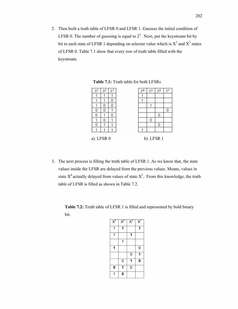
202
2. Then built a truth table of LFSR 0 and LFSR 1. Guesses the initial condition of
LFSR 0. The number of guessing is equal to 23. Next, put the keystream bit by
bit to each state of LFSR 1 depending on selector value which is X3 and X2 states
of LFSR 0. Table 7.1 show that every row of truth table filled with the
keystream.
Table 7.1: Truth table for both LFSRs
a). LFSR 0 b). LFSR 1
3. The next process is filling the truth table of LFSR 1. As we know that, the state
values inside the LFSR are delayed from the previous values. Means, values in
state X4 actually delayed from values of state X3. From this knowledge, the truth
table of LFSR is filled as shown in Table 7.2.
Table 7.2: Truth table of LFSR 1 is filled and represented by bold binary
bit. X4 X3 X2 X1
1 1 1
1 1
1
1 0
0 1
0 1 0
0 1 0
1 0

203
4. Based on polynomial used where the state of X1 is an output of XOR process
between X3 and X4, continue filling the truth table. Now, the truth table is
become as Table 7.3.
Table 7.3: Another binary bit recovered from the polynomial knowledge. X4 X3 X2 X1
1 1 1
1 1 0
1 1
1 0 0
0 1
0 1 0
0 1 0
1 0 1
5. Repeat the step 3 and 4 until all binary bits is filled in truth table as shown in
Table 7.4.
Table 7.4: The secret key is represented by bold binary bit. X4 X3 X2 X1
1 1 1 1
1 1 1 0
1 1 0 0
1 0 0 0
0 0 0 1
0 0 1 0
0 1 0 0
1 0 0 1
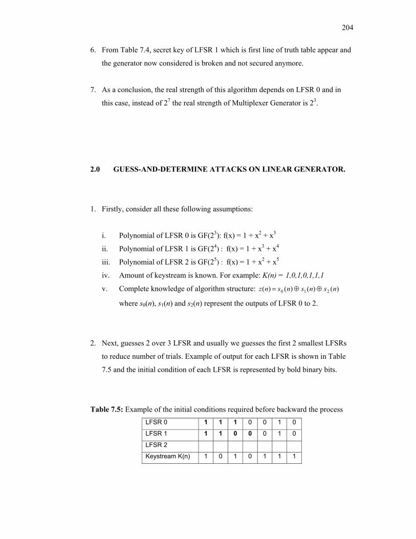
204
6. From Table 7.4, secret key of LFSR 1 which is first line of truth table appear and
the generator now considered is broken and not secured anymore.
7. As a conclusion, the real strength of this algorithm depends on LFSR 0 and in
this case, instead of 27 the real strength of Multiplexer Generator is 23.
2.0 GUESS-AND-DETERMINE ATTACKS ON LINEAR GENERATOR.
1. Firstly, consider all these following assumptions:
i. Polynomial of LFSR 0 is GF(23): f(x) = 1 + x2 + x3
ii. Polynomial of LFSR 1 is GF(24) : f(x) = 1 + x3 + x4
iii. Polynomial of LFSR 2 is GF(25) : f(x) = 1 + x2 + x5
iv. Amount of keystream is known. For example: K(n) = 1,0,1,0,1,1,1
v. Complete knowledge of algorithm structure: )()()()( 210 nsnsnsnz ⊕⊕=
where s0(n), s1(n) and s2(n) represent the outputs of LFSR 0 to 2.
2. Next, guesses 2 over 3 LFSR and usually we guesses the first 2 smallest LFSRs
to reduce number of trials. Example of output for each LFSR is shown in Table
7.5 and the initial condition of each LFSR is represented by bold binary bits.
Table 7.5: Example of the initial conditions required before backward the process LFSR 0 1 1 1 0 0 1 0
LFSR 1 1 1 0 0 0 1 0
LFSR 2
Keystream K(n) 1 0 1 0 1 1 1
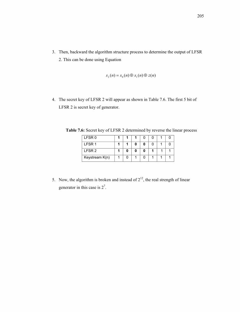
205
3. Then, backward the algorithm structure process to determine the output of LFSR
2. This can be done using Equation
)()()()( 102 nznsnsns ⊕⊕=
4. The secret key of LFSR 2 will appear as shown in Table 7.6. The first 5 bit of
LFSR 2 is secret key of generator.
Table 7.6: Secret key of LFSR 2 determined by reverse the linear process LFSR 0 1 1 1 0 0 1 0
LFSR 1 1 1 0 0 0 1 0
LFSR 2 1 0 0 0 1 1 1
Keystream K(n) 1 0 1 0 1 1 1
5. Now, the algorithm is broken and instead of 212, the real strength of linear
generator in this case is 27.

206
3.0 VERIFICATION OF CIPHER SYSTEM BASED ON LFSR
The verification of the cipher system was done by comparing between the keystream
that generated manually by calculation and produced from simulation software. Both
keystream should be the same. Below is an example of verification on Improved
Geffe generator using small registers. The configurations of the system are:
Register 1:
Size of register : 3
Coefficient : 101
Initial : 011
Register 2:
Size of register : 5
Coefficient : 10010
Initial : 10101
Register 3:
Size of register : 7
Coefficient : 1000001
Initial : 0001111
Table 7.7: Pseudorandom sequences produce by LFSR
Register Sequences
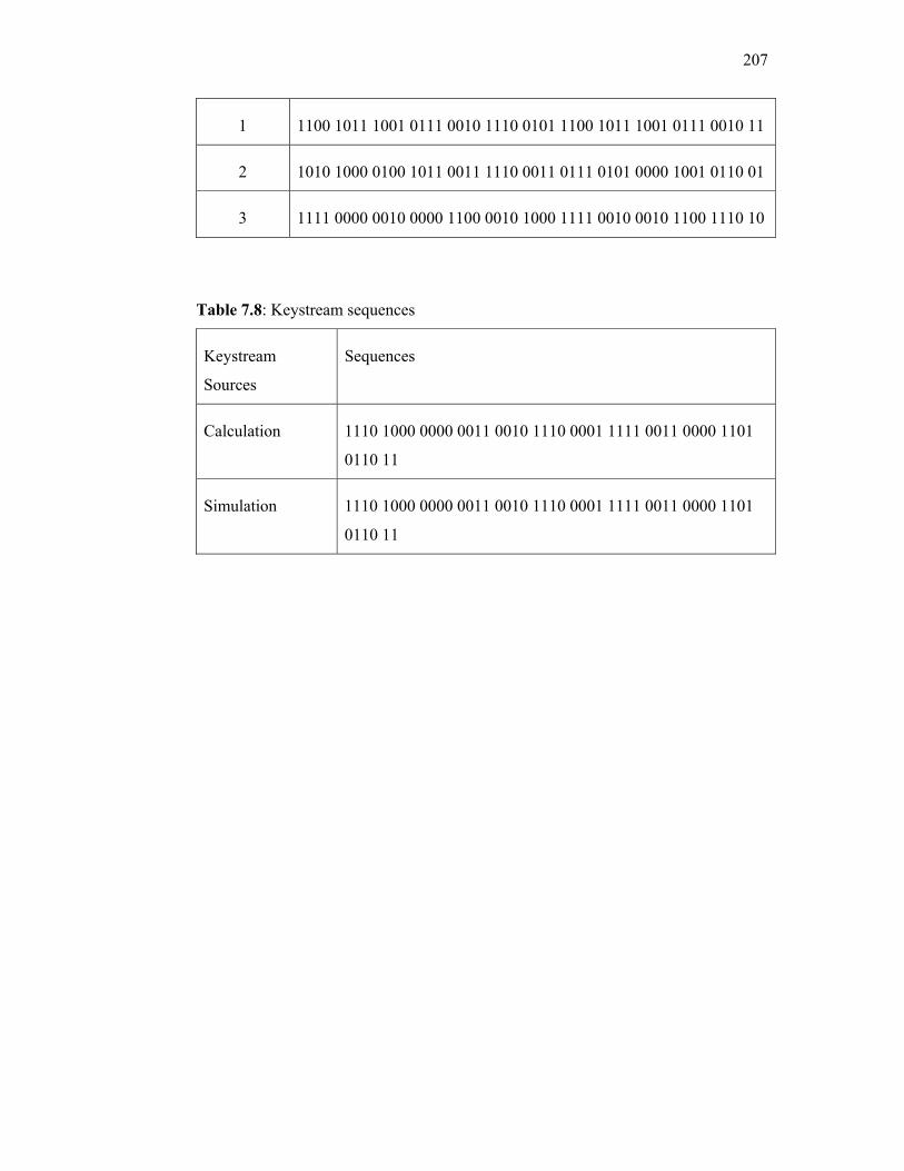
207
1 1100 1011 1001 0111 0010 1110 0101 1100 1011 1001 0111 0010 11
2 1010 1000 0100 1011 0011 1110 0011 0111 0101 0000 1001 0110 01
3 1111 0000 0010 0000 1100 0010 1000 1111 0010 0010 1100 1110 10
Table 7.8: Keystream sequences
Keystream
Sources
Sequences
Calculation 1110 1000 0000 0011 0010 1110 0001 1111 0011 0000 1101
0110 11
Simulation 1110 1000 0000 0011 0010 1110 0001 1111 0011 0000 1101
0110 11
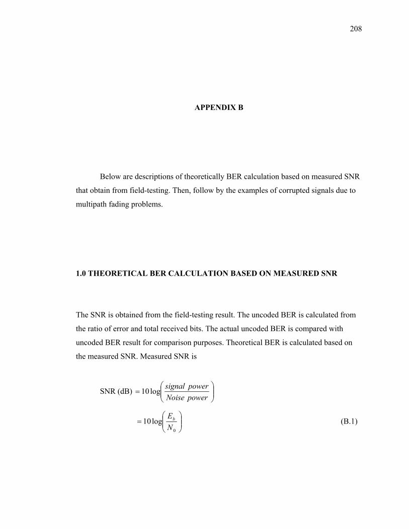
208
APPENDIX B
Below are descriptions of theoretically BER calculation based on measured SNR
that obtain from field-testing. Then, follow by the examples of corrupted signals due to
multipath fading problems.
1.0 THEORETICAL BER CALCULATION BASED ON MEASURED SNR
The SNR is obtained from the field-testing result. The uncoded BER is calculated from
the ratio of error and total received bits. The actual uncoded BER is compared with
uncoded BER result for comparison purposes. Theoretical BER is calculated based on
the measured SNR. Measured SNR is
SNR (dB)
=
powerNoisepowersignallog10
=
0
log10NEb (B.1)
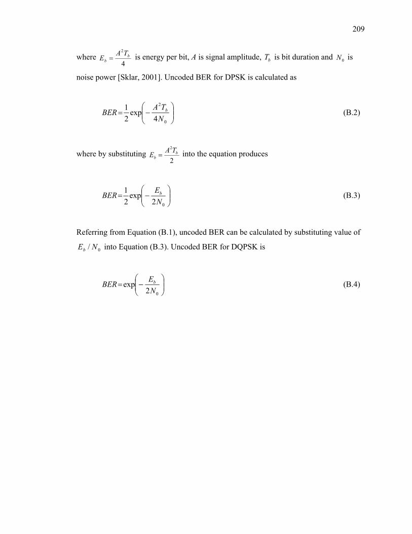
209
where 4
2b
bTA
E = is energy per bit, A is signal amplitude, bT is bit duration and 0N is
noise power [Sklar, 2001]. Uncoded BER for DPSK is calculated as
−=
0
2
4exp
21
NTA
BER b (B.2)
where by substituting 2
2b
bTAE = into the equation produces
−=
02exp
21
NEBER b (B.3)
Referring from Equation (B.1), uncoded BER can be calculated by substituting value of
0/ NEb into Equation (B.3). Uncoded BER for DQPSK is
−=
02exp
NEBER b (B.4)
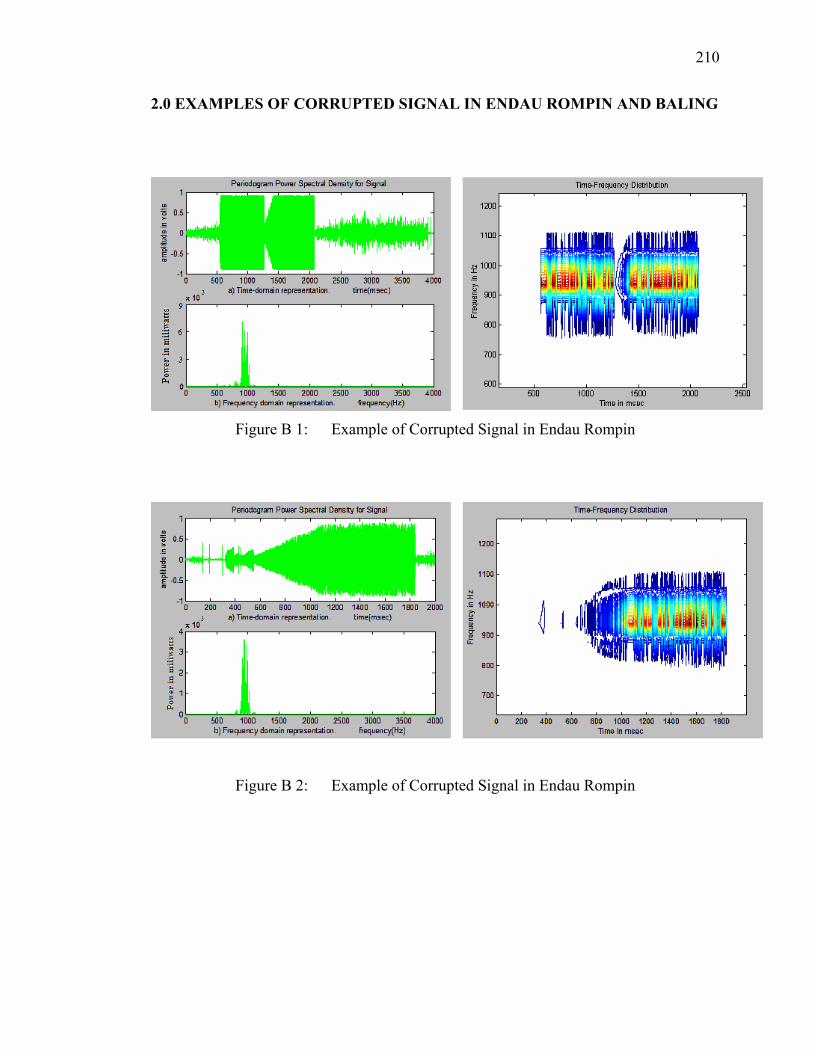
210
2.0 EXAMPLES OF CORRUPTED SIGNAL IN ENDAU ROMPIN AND BALING
Figure B 1: Example of Corrupted Signal in Endau Rompin
Figure B 2: Example of Corrupted Signal in Endau Rompin
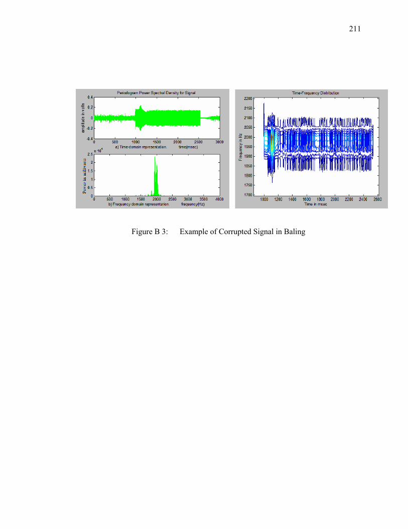
211
Figure B 3: Example of Corrupted Signal in Baling
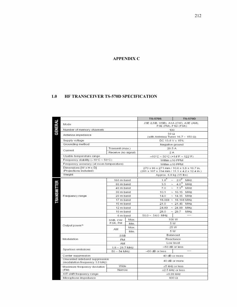
212
APPENDIX C
1.0 HF TRANSCEIVER TS-570D SPECIFICATION
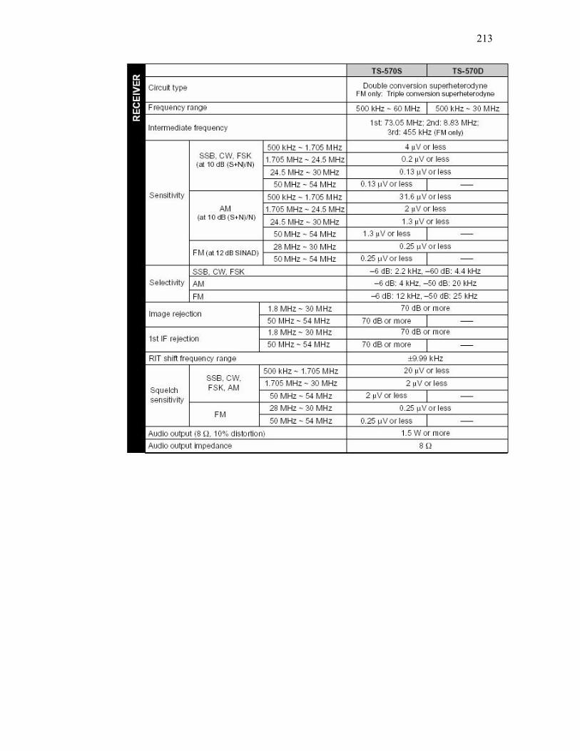
213
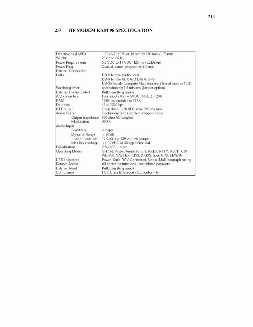
214
2.0 HF MODEM KAM’98 SPECIFICATION
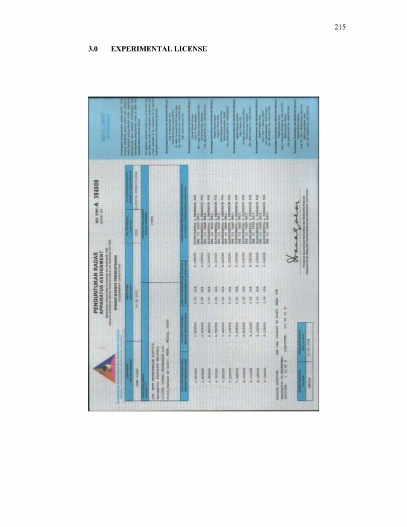
215
3.0 EXPERIMENTAL LICENSE
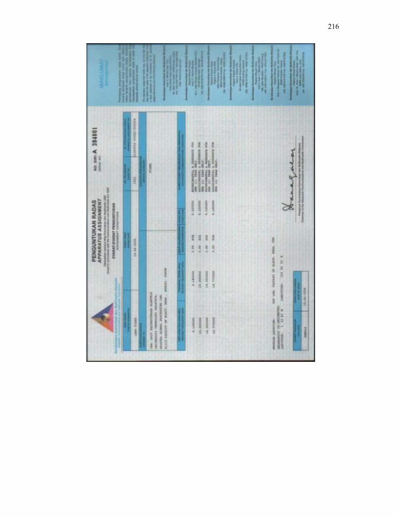
216
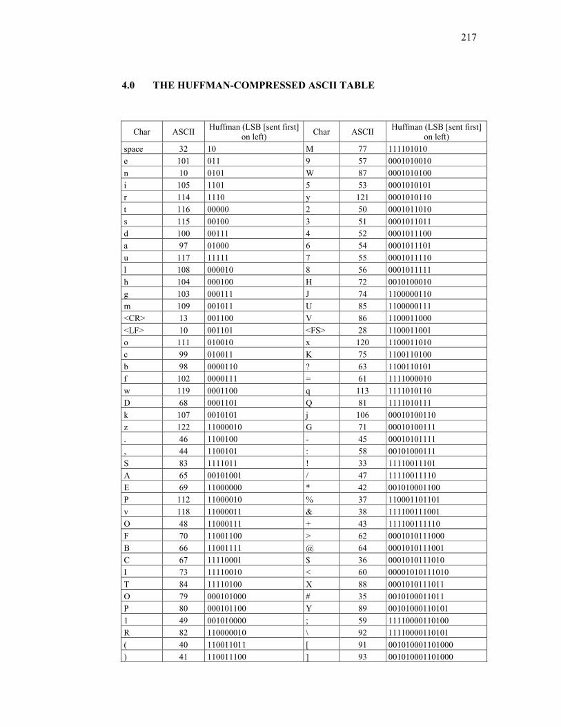
217
4.0 THE HUFFMAN-COMPRESSED ASCII TABLE
Char ASCII Huffman (LSB [sent first] on left) Char ASCII Huffman (LSB [sent first]
on left) space 32 10 M 77 111101010 e 101 011 9 57 0001010010 n 10 0101 W 87 0001010100 i 105 1101 5 53 0001010101 r 114 1110 y 121 0001010110 t 116 00000 2 50 0001011010 s 115 00100 3 51 0001011011 d 100 00111 4 52 0001011100 a 97 01000 6 54 0001011101 u 117 11111 7 55 0001011110 l 108 000010 8 56 0001011111 h 104 000100 H 72 0010100010 g 103 000111 J 74 1100000110 m 109 001011 U 85 1100000111 <CR> 13 001100 V 86 1100011000 <LF> 10 001101 <FS> 28 1100011001 o 111 010010 x 120 1100011010 c 99 010011 K 75 1100110100 b 98 0000110 ? 63 1100110101 f 102 0000111 = 61 1111000010 w 119 0001100 q 113 1111010110 D 68 0001101 Q 81 1111010111 k 107 0010101 j 106 00010100110 z 122 11000010 G 71 00010100111 . 46 1100100 - 45 00010101111 , 44 1100101 : 58 00101000111 S 83 1111011 ! 33 11110011101 A 65 00101001 / 47 11110011110 E 69 11000000 * 42 001010001100 P 112 11000010 % 37 110001101101 v 118 11000011 & 38 111100111001 O 48 11000111 + 43 111100111110 F 70 11001100 > 62 0001010111000 B 66 11001111 @ 64 0001010111001 C 67 11110001 $ 36 0001010111010 I 73 11110010 < 60 00001010111010 T 84 11110100 X 88 0001010111011 O 79 000101000 # 35 0010100011011 P 80 000101100 Y 89 00101000110101 1 49 001010000 ; 59 11110000110100 R 82 110000010 \ 92 11110000110101 ( 40 110011011 [ 91 001010001101000 ) 41 110011100 ] 93 001010001101000
218
L 76 110011101 <DEL> 127 110001101111000 N 78 111100000 ~ 126 110001101111001 Z 90 111100110 } 125 110001101111010 | 124 110001101111011 { 123 110001101111100
5.0 EXAMPLES OF TEXT FILES
5.1 4 Kbytes Text File ================================================================== MICROSOFT FOUNDATION CLASS LIBRARY : comm ================================================================== AppWizard has created this comm application for you. This application not only demonstrates the basics of using the Microsoft Foundation classes but is also a starting point for writing your application. This file contains a summary of what you will find in each of the files that make up your comm application. comm.dsp This file (the project file) contains information at the project level and is used to build a single project or subproject. Other users can share the project (.dsp) file, but they should export the make files locally. comm.h This is the main header file for the application. It includes other project specific headers (including Resource.h) and declares the CCommApp application class. comm.cpp This is the main application source file that contains the application class CCommApp. comm.rc This is a listing of all of the Microsoft Windows resources that the program uses. It includes the icons, bitmaps, and cursors that are stored in the RES subdirectory. This file can be directly edited in Microsoft Visual C++.
219
comm.clw This file contains information used by ClassWizard to edit existing classes or add new classes. ClassWizard also uses this file to store information needed to create and edit message maps and dialog data maps and to create prototype member functions. res\comm.ico This is an icon file, which is used as the application's icon. This icon is included by the main resource file comm.rc. res\comm.rc2 This file contains resources that are not edited by Microsoft Visual C++. You should place all resources not editable by the resource editor in this file. ///////////////////////////////////////////////////////////////////////////// AppWizard creates one dialog class: commDlg.h, commDlg.cpp - the dialog These files contain your CCommDlg class. This class defines the behavior of your application's main dialog. The dialog's template is in comm.rc, which can be edited in Microsoft Visual C++. ///////////////////////////////////////////////////////////////////////////// Other standard files: StdAfx.h, StdAfx.cpp These files are used to build a precompiled header (PCH) file named comm.pch and a precompiled types file named StdAfx.obj. Resource.h This is the standard header file, which defines new resource IDs. Microsoft Visual C++ reads and updates this file. ///////////////////////////////////////////////////////////////////////////// Other notes: AppWizard uses "TODO:" to indicate parts of the source code you should add to or customize.
220
If your application uses MFC in a shared DLL, and your application is in a language other than the operating system's current language, you will need to copy the corresponding localized resources MFC42XXX.DLL from the Microsoft Visual C++ CD-ROM onto the system or system32 directory, and rename it to be MFCLOC.DLL. ("XXX" stands for the language abbreviation. For example, MFC42DEU.DLL contains resources translated to German.) If you don't do this, some of the UI elements of your application will remain in the language of the operating system. ///////////////////////////////////////////////////////////////////////////// 5.2 3 Kbytes text file 1.0 Title Performance Analysis of Differential Phase Modulation for HF Digital Communication 2.0 Introduction The existence of essential electrons in ionosphere makes long distance communication possible. Some of ionosphere layers act like mirror where the signal in the ionosphere experience maximum refraction, that they are bent back toward the earth’s surface. This characteristic makes skywave propagation using high frequency (HF) available while for short distance transmissions, groundwave propagation will be used. Transmission using HF spectrum (3-30MHz) is required to get a system that available to operate over a broad range of adverse channel, due to ionosphere variability. These problems makes HF left behind compared to satellite and fiber optic communication network. However, HF spectrum is still widely used for tactical and strategic military purpose. Besides that, HF communication system requires minimum infrastructure at low cost, on the other hand satellite communication requires a very high cost and frequent maintenance. Transmission over HF communication system is operated without the need to use the service of third party which much more secure compared to transmission using satellite. The sender and the receiver will only require HF transceiver and HF modem. Privacy is guaranteed for HF communication because the medium is not control by anyone whereas for satellite communication, the satellite company will undoubtedly have the access to the information. The problem of wear and tear will arise in satellite communication, for HF communication this problem does not exist. The purpose of this project is to develop a digital communication system through HF. Design and analyze of multi-phase digital modulation technique that combat variability’s of channel effect and perform higher data transmission rate through HF.
221
3.0 Problem Statement In HF communication, the variability of ionosphere results multipath fading phenomenon. This phenomenon gives several affects in the communication, which are time delay spread, Doppler shift and time selective fading. Due to time delay spread problem, system can only transmit data to 100 boud per second. A serious time delay spread problem will cause for inter symbol interference (ISI). By limiting the data transmission rate to 100 baud per There are several problems to be focused as listed below: 1. How to combat the nature of the channel, and 2. How to improve the reliability in data transmission that enables data
transmission rate greater than 100 bits per second. 3. What is the technique can be used in order to improve the reliability in data
transmission. As a solution, to increase the data transmission rate without changing or increasing the baud rate, differential phase modulation is used. 4.0 Objective The main objective of this project is to design, simulate and analysis a HF communication system that combats the variability’s of channel effects
222
6.0 EXAMPLES OF JPEG IMAGE
6.1 5 Kbytes image
6.2 6 Kbytes image
6.3 10 Kbytes image
223
6.4 12 Kbytes image
6.5 4 Kbytes image
224
6.6 9 Kbytes image
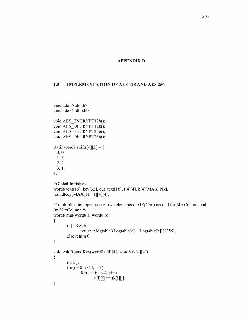
203
APPENDIX D
1.0 IMPLEMENTATION OF AES 128 AND AES 256
#include <stdio.h> #include <stdlib.h> void AES_ENCRYPT128(); void AES_DECRYPT128(); void AES_ENCRYPT256(); void AES_DECRYPT256(); static word8 shifts[4][2] = { 0, 0, 1, 3, 2, 2, 3, 1, }; //Global Initialize word8 text[16], key[32], out_text[16], t[4][4], k[4][MAX_Nk], roundKey[MAX_Nr+1][4][4]; /* multiplication operation of two elements of GF(2^m) needed for MixColumn and InvMixColumn */ word8 mul(word8 a, word8 b) { if (a && b) return Alogtable[(Logtable[a] + Logtable[b])%255]; else return 0; } void AddRoundKey(word8 a[4][4], word8 rk[4][4]) { int i, j; for(i = 0; i < 4; i++) for(j = 0; j < 4; j++) a[i][j] ^= rk[i][j]; }
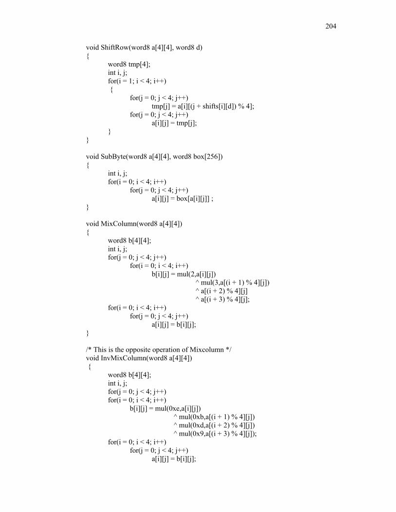
204
void ShiftRow(word8 a[4][4], word8 d) { word8 tmp[4]; int i, j; for(i = 1; i < 4; i++)
{ for(j = 0; j < 4; j++) tmp[j] = a[i][(j + shifts[i][d]) % 4]; for(j = 0; j < 4; j++) a[i][j] = tmp[j]; } } void SubByte(word8 a[4][4], word8 box[256]) { int i, j; for(i = 0; i < 4; i++) for(j = 0; j < 4; j++) a[i][j] = box[a[i][j]] ; } void MixColumn(word8 a[4][4]) { word8 b[4][4]; int i, j; for(j = 0; j < 4; j++) for(i = 0; i < 4; i++) b[i][j] = mul(2,a[i][j]) ^ mul(3,a[(i + 1) % 4][j]) ^ a[(i + 2) % 4][j] ^ a[(i + 3) % 4][j]; for(i = 0; i < 4; i++) for(j = 0; j < 4; j++) a[i][j] = b[i][j]; } /* This is the opposite operation of Mixcolumn */ void InvMixColumn(word8 a[4][4]) { word8 b[4][4]; int i, j; for(j = 0; j < 4; j++) for(i = 0; i < 4; i++) b[i][j] = mul(0xe,a[i][j]) ^ mul(0xb,a[(i + 1) % 4][j]) ^ mul(0xd,a[(i + 2) % 4][j]) ^ mul(0x9,a[(i + 3) % 4][j]); for(i = 0; i < 4; i++) for(j = 0; j < 4; j++) a[i][j] = b[i][j];
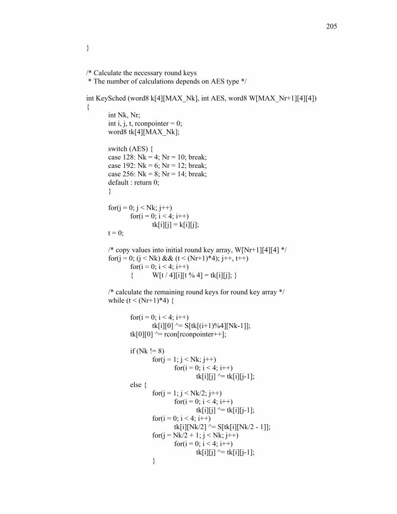
205
} /* Calculate the necessary round keys * The number of calculations depends on AES type */ int KeySched (word8 k[4][MAX_Nk], int AES, word8 W[MAX_Nr+1][4][4]) { int Nk, Nr; int i, j, t, rconpointer = 0; word8 tk[4][MAX_Nk]; switch (AES) { case 128: Nk = 4; Nr = 10; break; case 192: Nk = 6; Nr = 12; break; case 256: Nk = 8; Nr = 14; break; default : return 0; } for(j = 0; j < Nk; j++) for(i = 0; i < 4; i++) tk[i][j] = k[i][j]; t = 0; /* copy values into initial round key array, W[Nr+1][4][4] */ for(j = 0; (j < Nk) && (t < (Nr+1)*4); j++, t++) for(i = 0; i < 4; i++) { W[t / 4][i][t % 4] = tk[i][j]; } /* calculate the remaining round keys for round key array */ while (t < (Nr+1)*4) { for(i = 0; i < 4; i++) tk[i][0] ^= S[tk[(i+1)%4][Nk-1]]; tk[0][0] ^= rcon[rconpointer++]; if (Nk != 8) for(j = 1; j < Nk; j++) for(i = 0; i < 4; i++) tk[i][j] ^= tk[i][j-1]; else { for(j = 1; j < Nk/2; j++) for(i = 0; i < 4; i++) tk[i][j] ^= tk[i][j-1]; for(i = 0; i < 4; i++) tk[i][Nk/2] ^= S[tk[i][Nk/2 - 1]]; for(j = Nk/2 + 1; j < Nk; j++) for(i = 0; i < 4; i++) tk[i][j] ^= tk[i][j-1]; }
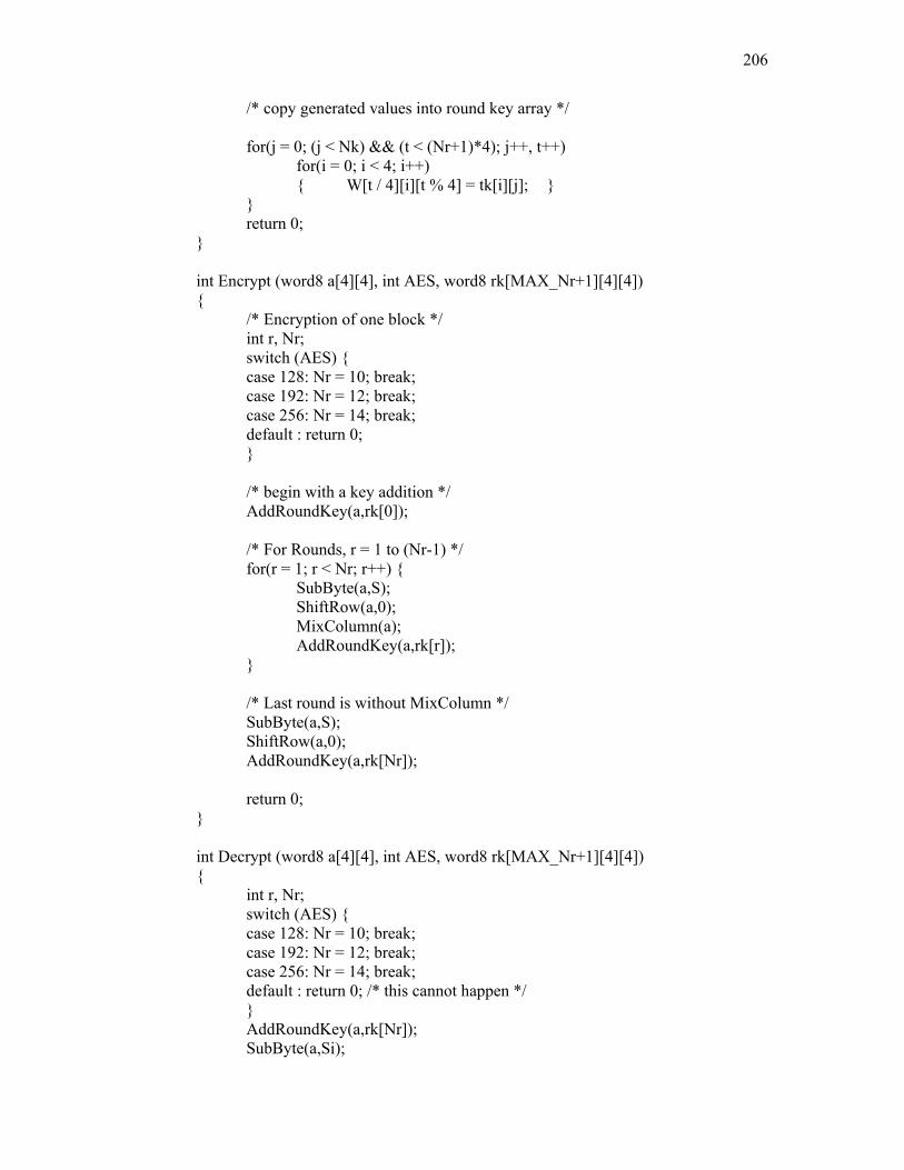
206
/* copy generated values into round key array */ for(j = 0; (j < Nk) && (t < (Nr+1)*4); j++, t++) for(i = 0; i < 4; i++) { W[t / 4][i][t % 4] = tk[i][j]; } } return 0; } int Encrypt (word8 a[4][4], int AES, word8 rk[MAX_Nr+1][4][4]) { /* Encryption of one block */ int r, Nr; switch (AES) { case 128: Nr = 10; break; case 192: Nr = 12; break; case 256: Nr = 14; break; default : return 0; } /* begin with a key addition */ AddRoundKey(a,rk[0]); /* For Rounds, r = 1 to (Nr-1) */ for(r = 1; r < Nr; r++) { SubByte(a,S); ShiftRow(a,0); MixColumn(a); AddRoundKey(a,rk[r]); } /* Last round is without MixColumn */ SubByte(a,S); ShiftRow(a,0); AddRoundKey(a,rk[Nr]); return 0; } int Decrypt (word8 a[4][4], int AES, word8 rk[MAX_Nr+1][4][4]) { int r, Nr; switch (AES) { case 128: Nr = 10; break; case 192: Nr = 12; break; case 256: Nr = 14; break; default : return 0; /* this cannot happen */ } AddRoundKey(a,rk[Nr]); SubByte(a,Si);
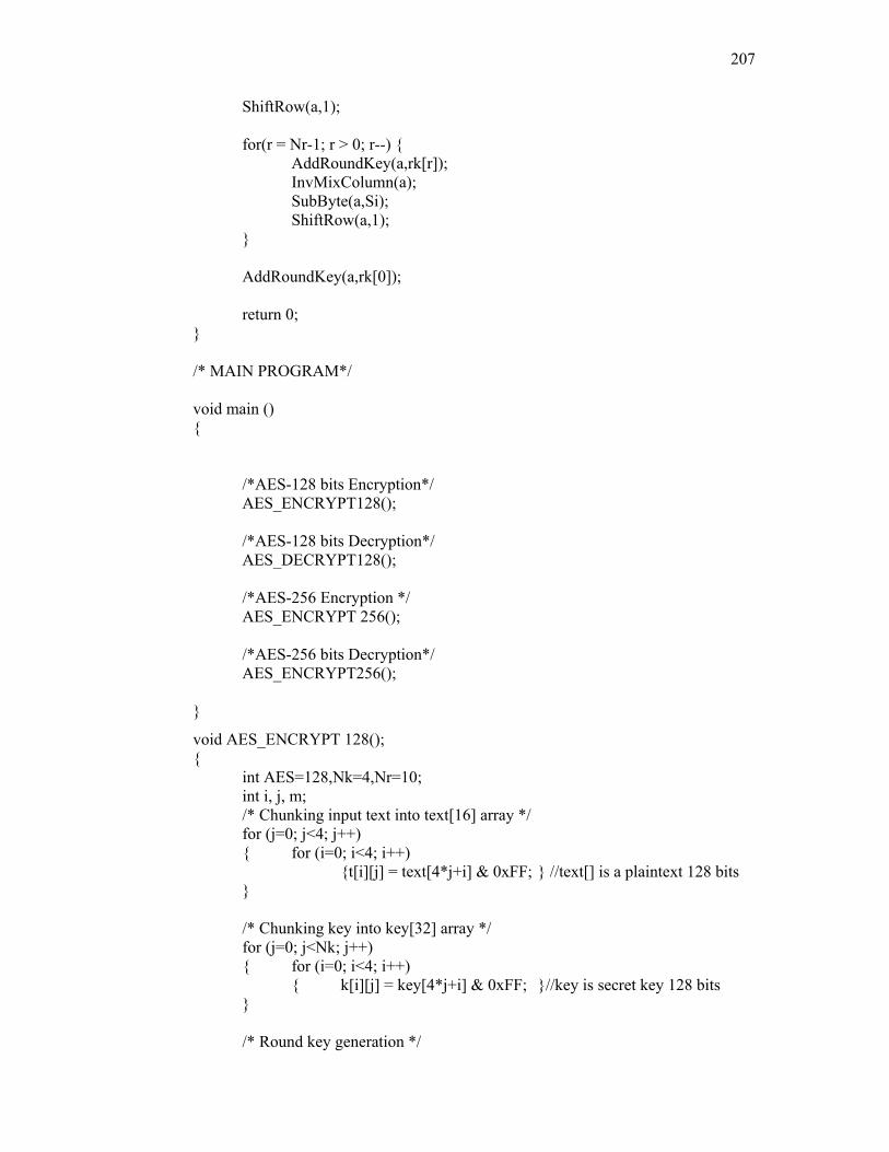
207
ShiftRow(a,1); for(r = Nr-1; r > 0; r--) { AddRoundKey(a,rk[r]); InvMixColumn(a); SubByte(a,Si); ShiftRow(a,1); } AddRoundKey(a,rk[0]); return 0; } /* MAIN PROGRAM*/ void main () { /*AES-128 bits Encryption*/ AES_ENCRYPT128(); /*AES-128 bits Decryption*/ AES_DECRYPT128(); /*AES-256 Encryption */ AES_ENCRYPT 256(); /*AES-256 bits Decryption*/ AES_ENCRYPT256(); }
void AES_ENCRYPT 128(); { int AES=128,Nk=4,Nr=10; int i, j, m; /* Chunking input text into text[16] array */ for (j=0; j<4; j++) { for (i=0; i<4; i++)
{t[i][j] = text[4*j+i] & 0xFF; } //text[] is a plaintext 128 bits } /* Chunking key into key[32] array */ for (j=0; j<Nk; j++) { for (i=0; i<4; i++) { k[i][j] = key[4*j+i] & 0xFF; }//key is secret key 128 bits } /* Round key generation */
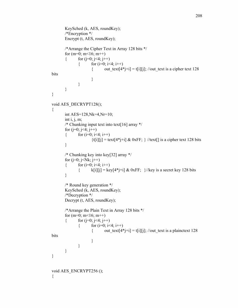
208
KeySched (k, AES, roundKey); /*Encryption */ Encrypt (t, AES, roundKey); /*Arrange the Cipher Text in Array 128 bits */ for (m=0; m<16; m++) { for (j=0; j<4; j++) { for (i=0; i<4; i++) { out_text[4*j+i] = t[i][j]; //out_text is a cipher text 128 bits } } } } void AES_DECRYPT128(); { int AES=128,Nk=4,Nr=10; int i, j, m; /* Chunking input text into text[16] array */ for (j=0; j<4; j++) { for (i=0; i<4; i++)
{t[i][j] = text[4*j+i] & 0xFF; } //text[] is a cipher text 128 bits } /* Chunking key into key[32] array */ for (j=0; j<Nk; j++) { for (i=0; i<4; i++) { k[i][j] = key[4*j+i] & 0xFF; }//key is a secret key 128 bits } /* Round key generation */ KeySched (k, AES, roundKey); /*Decryption */ Decrypt (t, AES, roundKey); /*Arrange the Plain Text in Array 128 bits */ for (m=0; m<16; m++) { for (j=0; j<4; j++) { for (i=0; i<4; i++) { out_text[4*j+i] = t[i][j]; //out_text is a plainctext 128 bits } } } } void AES_ENCRYPT256 (); {

209
int AES=256,Nk=8,Nr=14; int i, j, m; /* Chunking input text into text[16] array */ for (j=0; j<4; j++) { for (i=0; i<4; i++)
{t[i][j] = text[4*j+i] & 0xFF; } //text[] is a plaintext 256 bits } /* Chunking key into key[32] array */ for (j=0; j<Nk; j++) { for (i=0; i<4; i++) { k[i][j] = key[4*j+i] & 0xFF; }//key is a secret key 256 bit } /* Round key generation */ KeySched (k, AES, roundKey); /*Encryption */ Encrypt (t, AES, roundKey); /*Arrange the Cipher Text in Array 128 bits */ for (m=0; m<16; m++) { for (j=0; j<4; j++) { for (i=0; i<4; i++) { out_text[4*j+i] = t[i][j]; //out_text is a cipher text 256 bits } } } } void AES_DECRYPT256(); { int AES=256,Nk=8,Nr=14; int i, j, m; /* Chunking input text into text[16] array */ for (j=0; j<4; j++) { for (i=0; i<4; i++)
{t[i][j] = text[4*j+i] & 0xFF; } //text[] is a cipher text 128 bits } /* Chunking key into key[32] array */ for (j=0; j<Nk; j++) { for (i=0; i<4; i++) { k[i][j] = key[4*j+i] & 0xFF; }//key is a secret key 256 bit } /* Round key generation */ KeySched (k, AES, roundKey); /*Decryption */ Decrypt (t, AES, roundKey);
210
/*Arrange the Plain Text in Array 128 bits */ for (m=0; m<16; m++) { for (j=0; j<4; j++) { for (i=0; i<4; i++) { out_text[4*j+i] = t[i][j]; //out_text is a plainctext 128 bits } } } }
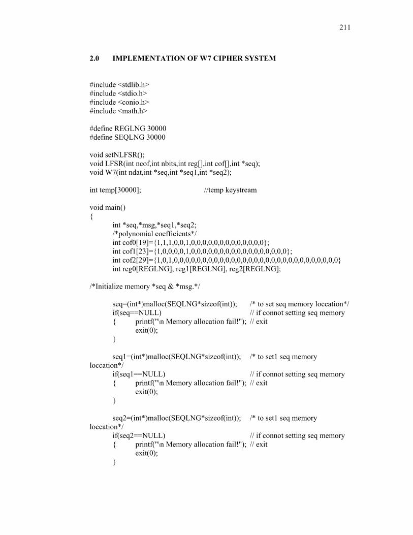
211
2.0 IMPLEMENTATION OF W7 CIPHER SYSTEM
#include <stdlib.h> #include <stdio.h> #include <conio.h> #include <math.h> #define REGLNG 30000 #define SEQLNG 30000 void setNLFSR(); void LFSR(int ncof,int nbits,int reg[],int cof[],int *seq); void W7(int ndat,int *seq,int *seq1,int *seq2); int temp[30000]; //temp keystream void main() { int *seq,*msg,*seq1,*seq2; /*polynomial coefficients*/
int cof0[19]={1,1,1,0,0,1,0,0,0,0,0,0,0,0,0,0,0,0,0}; int cof1[23]={1,0,0,0,0,1,0,0,0,0,0,0,0,0,0,0,0,0,0,0,0,0,0}; int cof2[29]={1,0,1,0,0,0,0,0,0,0,0,0,0,0,0,0,0,0,0,0,0,0,0,0,0,0,0,0,0,0,0,0} int reg0[REGLNG], reg1[REGLNG], reg2[REGLNG];
/*Initialize memory *seq & *msg.*/ seq=(int*)malloc(SEQLNG*sizeof(int)); /* to set seq memory loccation*/ if(seq==NULL) // if connot setting seq memory { printf("\n Memory allocation fail!"); // exit exit(0); } seq1=(int*)malloc(SEQLNG*sizeof(int)); /* to set1 seq memory loccation*/ if(seq1==NULL) // if connot setting seq memory { printf("\n Memory allocation fail!"); // exit exit(0); } seq2=(int*)malloc(SEQLNG*sizeof(int)); /* to set1 seq memory loccation*/ if(seq2==NULL) // if connot setting seq memory { printf("\n Memory allocation fail!"); // exit exit(0); }
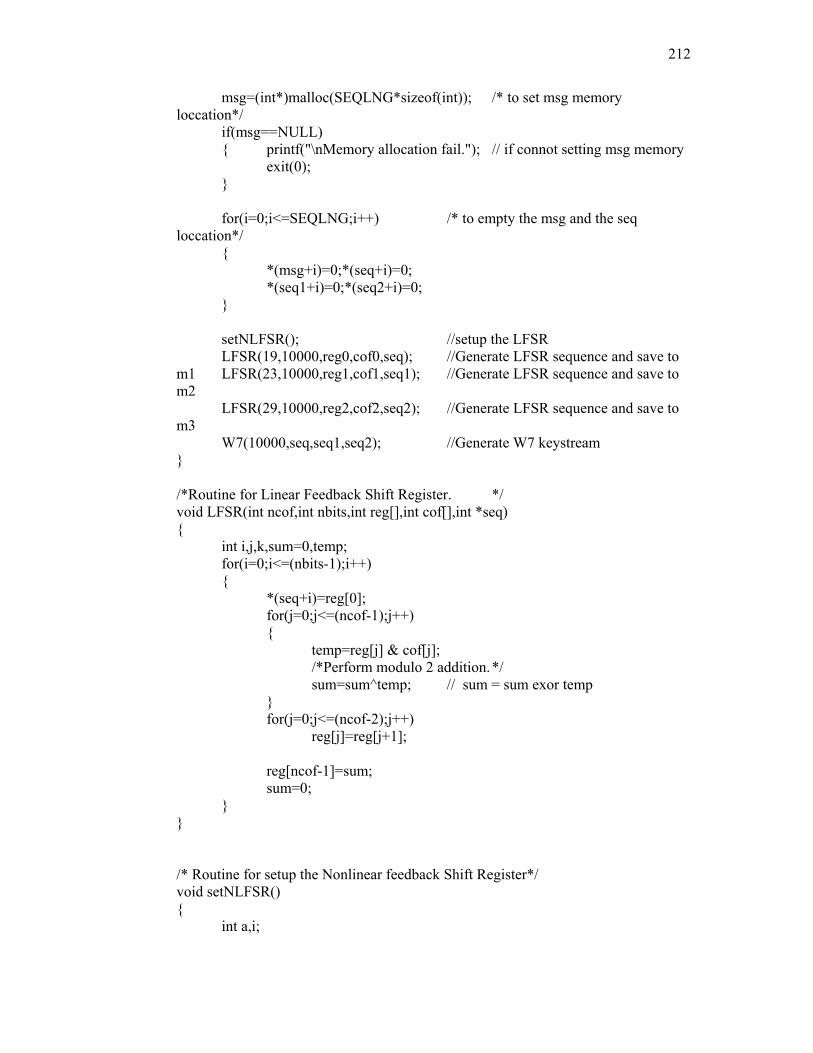
212
msg=(int*)malloc(SEQLNG*sizeof(int)); /* to set msg memory loccation*/ if(msg==NULL) { printf("\nMemory allocation fail."); // if connot setting msg memory exit(0); } for(i=0;i<=SEQLNG;i++) /* to empty the msg and the seq loccation*/ { *(msg+i)=0;*(seq+i)=0; *(seq1+i)=0;*(seq2+i)=0; } setNLFSR(); //setup the LFSR LFSR(19,10000,reg0,cof0,seq); //Generate LFSR sequence and save to m1 LFSR(23,10000,reg1,cof1,seq1); //Generate LFSR sequence and save to m2 LFSR(29,10000,reg2,cof2,seq2); //Generate LFSR sequence and save to m3 W7(10000,seq,seq1,seq2); //Generate W7 keystream } /*Routine for Linear Feedback Shift Register. */ void LFSR(int ncof,int nbits,int reg[],int cof[],int *seq) { int i,j,k,sum=0,temp; for(i=0;i<=(nbits-1);i++) { *(seq+i)=reg[0]; for(j=0;j<=(ncof-1);j++) { temp=reg[j] & cof[j];
/*Perform modulo 2 addition. */ sum=sum^temp; // sum = sum exor temp } for(j=0;j<=(ncof-2);j++) reg[j]=reg[j+1]; reg[ncof-1]=sum; sum=0; } } /* Routine for setup the Nonlinear feedback Shift Register*/ void setNLFSR() { int a,i;
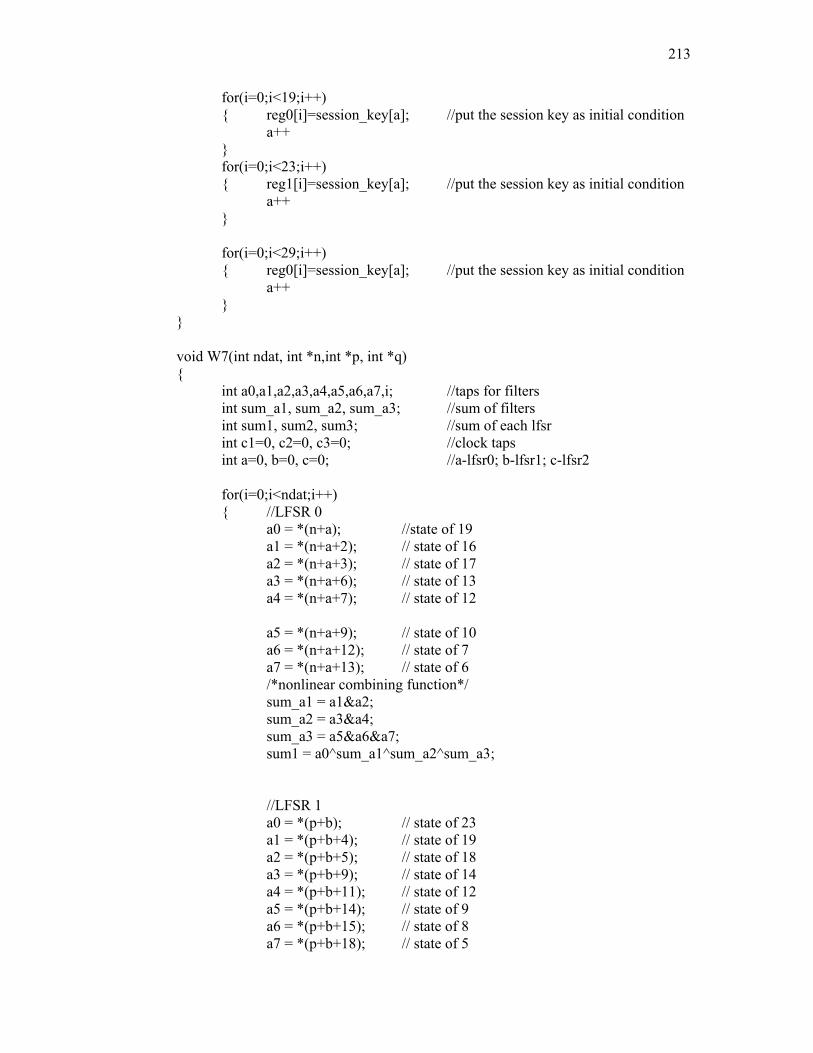
213
for(i=0;i<19;i++) { reg0[i]=session_key[a]; //put the session key as initial condition a++ } for(i=0;i<23;i++) { reg1[i]=session_key[a]; //put the session key as initial condition a++ } for(i=0;i<29;i++) { reg0[i]=session_key[a]; //put the session key as initial condition a++ } } void W7(int ndat, int *n,int *p, int *q) { int a0,a1,a2,a3,a4,a5,a6,a7,i; //taps for filters int sum_a1, sum_a2, sum_a3; //sum of filters int sum1, sum2, sum3; //sum of each lfsr int c1=0, c2=0, c3=0; //clock taps int a=0, b=0, c=0; //a-lfsr0; b-lfsr1; c-lfsr2 for(i=0;i<ndat;i++) { //LFSR 0 a0 = *(n+a); //state of 19 a1 = *(n+a+2); // state of 16 a2 = *(n+a+3); // state of 17 a3 = *(n+a+6); // state of 13 a4 = *(n+a+7); // state of 12 a5 = *(n+a+9); // state of 10 a6 = *(n+a+12); // state of 7 a7 = *(n+a+13); // state of 6 /*nonlinear combining function*/ sum_a1 = a1&a2; sum_a2 = a3&a4; sum_a3 = a5&a6&a7; sum1 = a0^sum_a1^sum_a2^sum_a3; //LFSR 1 a0 = *(p+b); // state of 23 a1 = *(p+b+4); // state of 19 a2 = *(p+b+5); // state of 18 a3 = *(p+b+9); // state of 14 a4 = *(p+b+11); // state of 12 a5 = *(p+b+14); // state of 9 a6 = *(p+b+15); // state of 8 a7 = *(p+b+18); // state of 5
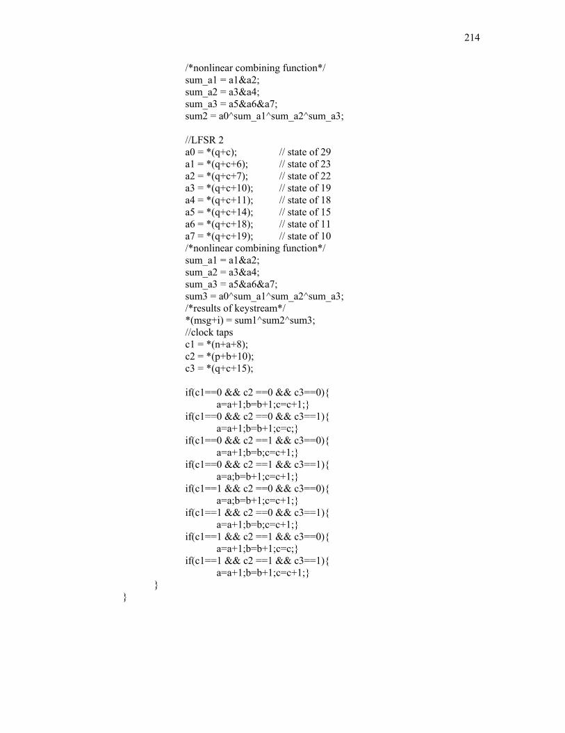
214
/*nonlinear combining function*/ sum_a1 = a1&a2; sum_a2 = a3&a4; sum_a3 = a5&a6&a7; sum2 = a0^sum_a1^sum_a2^sum_a3; //LFSR 2 a0 = *(q+c); // state of 29 a1 = *(q+c+6); // state of 23 a2 = *(q+c+7); // state of 22 a3 = *(q+c+10); // state of 19 a4 = *(q+c+11); // state of 18 a5 = *(q+c+14); // state of 15 a6 = *(q+c+18); // state of 11 a7 = *(q+c+19); // state of 10 /*nonlinear combining function*/ sum_a1 = a1&a2; sum_a2 = a3&a4; sum_a3 = a5&a6&a7; sum3 = a0^sum_a1^sum_a2^sum_a3; /*results of keystream*/ *(msg+i) = sum1^sum2^sum3; //clock taps c1 = *(n+a+8); c2 = *(p+b+10); c3 = *(q+c+15); if(c1==0 && c2 ==0 && c3==0){ a=a+1;b=b+1;c=c+1;} if(c1==0 && c2 ==0 && c3==1){ a=a+1;b=b+1;c=c;} if(c1==0 && c2 ==1 && c3==0){ a=a+1;b=b;c=c+1;} if(c1==0 && c2 ==1 && c3==1){ a=a;b=b+1;c=c+1;} if(c1==1 && c2 ==0 && c3==0){ a=a;b=b+1;c=c+1;} if(c1==1 && c2 ==0 && c3==1){ a=a+1;b=b;c=c+1;} if(c1==1 && c2 ==1 && c3==0){ a=a+1;b=b+1;c=c;} if(c1==1 && c2 ==1 && c3==1){ a=a+1;b=b+1;c=c+1;} } }
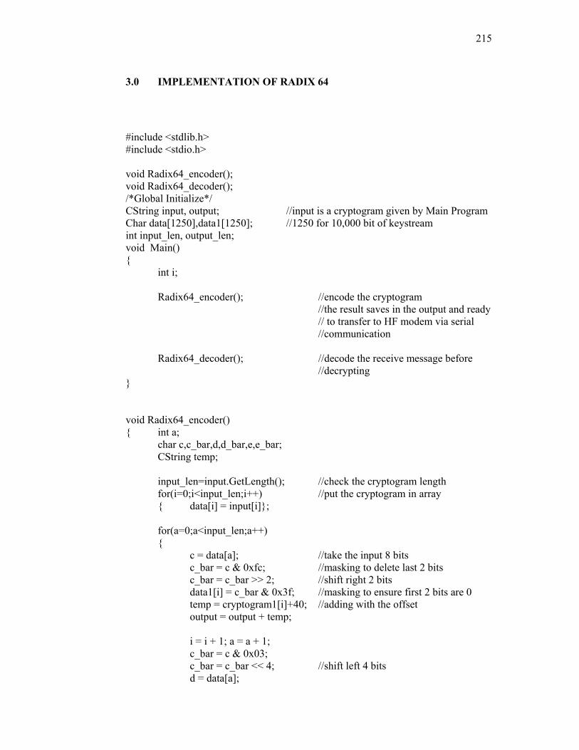
215
3.0 IMPLEMENTATION OF RADIX 64
#include <stdlib.h> #include <stdio.h> void Radix64_encoder(); void Radix64_decoder(); /*Global Initialize*/ CString input, output; //input is a cryptogram given by Main Program Char data[1250],data1[1250]; //1250 for 10,000 bit of keystream int input_len, output_len; void Main() { int i; Radix64_encoder(); //encode the cryptogram //the result saves in the output and ready // to transfer to HF modem via serial //communication Radix64_decoder(); //decode the receive message before //decrypting }
void Radix64_encoder() { int a; char c,c_bar,d,d_bar,e,e_bar; CString temp; input_len=input.GetLength(); //check the cryptogram length for(i=0;i<input_len;i++) //put the cryptogram in array { data[i] = input[i]}; for(a=0;a<input_len;a++) { c = data[a]; //take the input 8 bits c_bar = c & 0xfc; //masking to delete last 2 bits c_bar = c_bar >> 2; //shift right 2 bits data1[i] = c_bar & 0x3f; //masking to ensure first 2 bits are 0 temp = cryptogram1[i]+40; //adding with the offset output = output + temp; i = i + 1; a = a + 1; c_bar = c & 0x03; c_bar = c_bar << 4; //shift left 4 bits d = data[a];
216
d_bar = d & 0xf0; d_bar = d_bar >> 4; d_bar = d_bar & 0x0f; c_bar = c_bar | d_bar; data1[i] = c_bar & 0x3f; temp = data1[i]+40; output = output + temp; a = a + 1; d_bar = d & 0x0f; d_bar = d_bar << 2; e = data[a]; i = i + 1; e_bar = e & 0xc0; e_bar = e_bar >> 6; e_bar = e_bar & 0x03; e_bar = d_bar | e_bar; data1[i] = e_bar & 0x3f; temp = data1[i]+40; output =output + temp; i = i + 1; data1[i] = e & 0x3f; temp = data1[i]+40; output = output + temp; i = i + 1; } } void Radix64_decoder() { int a; char k, k_bar, l, l_bar, m, m_bar, n; char temp;
output_len=output.GetLength(); //check the receive message //length
for(i=0;i<output_len;i++) //put the message in array { temp = output[i]; temp = temp-40; //minus the 40 offset
data[i] = temp;} int p=0; for(a=0;a<output_len;a++) //rearrange the cryptogram {
217
k = data[a]; k_bar = k << 2; a = a + 1; l = data[a]; l_bar = l & 0x30; l_bar = l_bar >> 4; data1[p] = k_bar | l_bar; p = p + 1; l_bar = l & 0x0f; l_bar = l_bar << 4; a = a + 1; m = data[a]; m_bar = m & 0x3c; m_bar = m_bar >> 2; data1[p] = l_bar | m_bar; a = a + 1; p = p + 1; m_bar = m & 0x03; m_bar = m_bar << 6; n = data[a]; data1[p] = m_bar | n; p = p + 1; } }