section iii. hydrogen storage - eere.energy.gov · hydrogen, fuel cells, and infrastructure...
TRANSCRIPT

Hydrogen, Fuel Cells, and Infrastructure Technologies FY 2002 Progress Report
Section III. Hydrogen Storage
199

Hydrogen, Fuel Cells, and Infrastructure Technologies FY 2002 Progress Report
200

Hydrogen, Fuel Cells, and Infrastructure Technologies FY 2002 Progress Report
III.A High Pressure Tanks
III.A.1 Hydrogen Composite Tank Program
Neel Sirosh (Primary Contact), Andy Abele, Alan NiedzwieckiQUANTUM Technologies17872 Cartwright RoadIrvine, CA 92614(949) 399-4698, fax: (949) 399-4600, e-mail: [email protected]
DOE Technology Development Manager: Lucito Cataquiz(202) 586-0729, fax: (202) 586-9811, e-mail: [email protected]
Objectives• Develop, demonstrate and validate 5,000 pounds per square inch (psi) 7.5 wt % and 8.5 wt% Type IV
composite hydrogen storage tanks of specified sizes• Develop and validate 5,000 psi in-tank-regulators • Build, assemble, test and supply tank assemblies for DOE Future Truck and Nevada hydrogen bus
programs• Demonstrate 10,000 psi storage tanks
Approach• Optimize materials, design and processes related to QUANTUM "TriShield" composite fuel storage
tank technology to achieve high gravimetric efficiencies• Develop tanks for specific sizes and perform safety verification and validation tests based on NGV2-
2000, modified for high pressure hydrogen • Supply fully validated tank assemblies to DOE
Accomplishments• Achieved "World Record" hydrogen storage mass efficiency of 11.3 wt% on a prototype 5,000 psi
tank, with Lawrence Livermore National Laboratory and Thiokol Propulsion• Developed and demonstrated 7.5 wt % and 8.5 wt% Type IV composite hydrogen storage tanks of
specified sizes• Commenced shipping high efficiency TriShieldTM hydrogen storage tanks for a number of automotive
and stationary applications• Supplied tanks for Hyundai Santa Fe fuel cell electric vehicle, the first to fill to 5,000 psi hydrogen• Achieved European Integrated Hydrogen Project (EIHP) specifications for 5,000 psi hydrogen storage
tank, the first all-composite tank to achieve this• Achieved Canadian Standards Association certification for industry's first 5,000 psi (350 bar) in-tank
regulation system under NGV 3.1 standards• Designed and developed industry's first hydrogen 10,000 psi (700 bar) in-tank regulation system• Shipped tanks for DOE Future Truck and Nevada bus programs
201

Hydrogen, Fuel Cells, and Infrastructure Technologies FY 2002 Progress Report
Introduction
The objective of the DOE Hydrogen Composite Tank Project was to design, develop, validate, fabricate, and manufacture hydrogen fuel tanks (Figure 1) and in-tank regulators (Figure 2) along with vehicle integration brackets and isolators and have them delivered to Virginia Tech University and Texas Tech University in support of the Future Truck competition.
This project is part of the DOE program to demonstrate the feasibility of the use of compressed hydrogen as an automotive fuel. However, the lack of convenient and cost-effective hydrogen storage, particularly for an on-board vehicular system, is a major impediment to its widespread use. Improvements in the energy densities of hydrogen storage systems, reductions in cost, and increased compatibility with available and forecasted systems are required before viable hydrogen energy use will be realized. Possible approaches to hydrogen storage include: compression, liquefaction, chemical storage, metal hydrides, and adsorption. Although each storage method has desirable attributes, no approach currently satisfies all the efficiency, size, weight, cost, and safety requirements for transportation or utility use. Research continues in these areas, with progress being made in all approaches.
Currently there is a strong demand in the automotive market for cost-effective and efficient high-pressure hydrogen storage systems. The world's premier automotive original equipment manufacturer (OEMs) developing fuel cell vehicles have demonstrated significant interest in compressed hydrogen storage systems developed and validated by QUANTUM Technologies. The currently validated QUANTUM "TriShield" tank technology achieves 6% hydrogen by weight, 1,050 W-h/L, and 2,000 W-h/kg, meeting the DOE targets for percent weight and specific energy, and almost meeting the energy density target of 1,100 W-h/L. Significant cost reductions are possible with further optimization.
Approach
The QUANTUM advanced composite tank technology incorporates a "TriShieldTM" design
philosophy. The QUANTUM Type IV TriShieldTM cylinder, as illustrated Figure 3, is comprised of a seamless, one piece, permeation resistant, cross-linked ultra-high molecular weight polymer liner that
Figure 1. TriShieldTM Hydrogen Storage Tank
Figure 2. In-Tank High Pressure Regulator
Figure 3. TriShieldTM Tank Construction
202

Hydrogen, Fuel Cells, and Infrastructure Technologies FY 2002 Progress Report
is over wrapped with multiple layers of carbon fiber/epoxy laminate and a proprietary external protective layer for impact resistance. TriShieldTM hydrogen tanks feature a single-boss opening to minimize leak paths. The path to achieving high gravimetric efficiency is optimization in materials, design and processes. Numerical methods including the finite element method (see Figure 4) were employed to optimize the structural shell.
The TriShieldTM hydrogen tank is designed to accommodate QUANTUM's patented in-tank regulator, which confines high gas pressures within the tank and thus, eliminates high-pressure fuel lines downstream of the fuel storage subsystem. By combining a check valve to assist tank filling, fuel filtering, fuel tank pressure and temperature monitoring, pressure relief device and tank lock-off in the regulation module, the system cost can be significantly reduced.
Results
The 5,000 and 10,000-psi tanks developed by QUANTUM Technologies have been validated to meet the requirements of DOT FMVSS304, NGV2-2000 (both modified for hydrogen) and the draft EIHP standard. Typical safety tests completed, in order to ensure safety and reliability in an automotive service environment included burst tests (2.35 safety margin), fatigue, extreme temperature, hydrogen cycling, bonfire, severe drop impact test, flaw tolerance, acid environment, gunfire penetration, accelerated stress, permeation and material tests (Figrues 5 and 6). The developed "In-Tank-Regulators" meet the requirements of NGV3.1 and EIHP.
Hydrogen poses challenges, both real and perceived, as a transportation fuel. The most challenging application is the light-duty vehicle or, more specifically, the automobile. Automobiles impose the greatest constraints with respect to available space on-board the vehicle and consumer expectations for vehicle range. In the near-term, fuel cell vehicles will likely first be introduced for fleet applications in 2003-05. Fleet applications will likely have centralized refueling available, so a vehicle range of 100 - 150 miles (160 - 241 km)
would be acceptable. In terms of mass of hydrogen, this range could be achieved with about 3 kg of hydrogen supplying a fuel cell vehicle. Mature compressed and liquid hydrogen storage technologies of reasonable size and weight could achieve this short-term goal, as shown Table 1. Metal hydrides, although providing more compact storage, would impose a significant weight penalty.
Figure 4. Composite Shell Finite Element Model
Figure 5. Gunfire Test Example
Figure 6. Bonfire Test Example
203

Hydrogen, Fuel Cells, and Infrastructure Technologies FY 2002 Progress Report
Table 1. Current Status of Potential Short-term Hydrogen Storage Technologies for Volume and Weight Storing 3 kg H2
Short-term Goal: 3 kg H2 (215 km)
In the long-term, average consumers will expect fuel cell vehicles to be transparent compared to the gasoline-powered vehicles they drive today with respect to cost, convenience and operation. In fact, it is likely that fuel cell vehicles will have to offer a significant value proposition to encourage consumers to adopt a new technology rather than continue with something that is tried and true. Vehicle range will be an important factor to consumers, especially as a hydrogen-refueling infrastructure begins to develop. Fuel cell vehicle range of over 400 miles (644 km) will be needed, or roughly 7 kg of hydrogen stored on-board. Advanced storage materials, including alanate hydrides and carbon nano-structures, will have to emerge from the current conceptual stage to reduce hydrogen storage system size and weight, as shown in Table 2. However, both of these solid-state storage media are years from commercialization. QUANTUM's 10,000 psi TriShieldTM could potentially meet this long-term goal without significantly impacting either the passenger or storage compartments.
Table 2. Current Status of Potential Long-term Hydrogen Storage Technologies for Storing 7 kg H2
Long-term Goal: 7 kg H2 (700 km)
Conclusions
The technologies developed and validated under the DOE Hydrogen Composite project have played a key role in the commercialization of QUANTUM TriShieldTM tanks. In the near term, the markets for high-pressure hydrogen storage technology appear to be growing. Major automotive OEMs and bus OEMs are expected to be the major markets for this technology. In addition, QUANTUM sees growing interest in stationary and, especially, hydrogen refueling infrastructure applications for its advanced TriShieldTM storage tanks.
Presentations
1. Neel Sirosh, "Breakthroughs in Compressed Hydrogen Storage", Carbon Fiber 2000, San Antonio (2000)
2. Andris R. Abele, "Quantum's Experience - Leveraging DOE Funding to Accelerate Technology Development and Commercialization of Advanced Hydrogen Storage", NHA 12th Annual U.S. Hydrogen Meeting, Washington D.C. (2001)
3. Alan P. Niedzwiecki, "Advanced Hydrogen Storage to Enable Fuel Cell Vehicles", 14th World Hydrogen Energy Conference, Montreal, Quebec (2002)
4. Neel Sirosh, "Compressed Hydrogen Storage Technology", Hydrogen Storage: Gateway to Energy Security Workshop, Hilton Head Island (2002)
TechnologyStorage System
VolumeStorage System
Weight
5,000 psi Compressed H2 Tanks 145 L 45 kg
10,000 psi Compressed H2 Tanks 100 L 50 kg
Metal Hydrides 55 L 215 kg
Liquid H2 90 L 40 kg
TechnologyStorage System
VolumeStorage System
Weight
5,000 psi Compressed H2Tanks 320 L 90 kg
10,000 psi Compressed H2 Tanks 220 L 100 kg
Metal Hydrides 200 L 222 kg
Nanotubes ~130 L ~120 kg
204

Hydrogen, Fuel Cells, and Infrastructure Technologies FY 2002 Progress Report
III.A.2 Hydrogen Storage Using Lightweight Tanks
Andrew Weisberg (Primary Contact), Blake Myers, Gene BerryLawrence Livermore National LaboratoryP.O. Box 808Livermore, CA 94551(925) 422-7293, fax (925) 424-3731, e-mail: [email protected]
DOE Technology Development Manager: Lucito Cataquiz(202) 586-0729, fax : (202) 586-9811, e-mail : [email protected]
Objectives • Learn how to build and operate the best hydrogen container technologies• Explore the performance of recently discovered non-pressure-vessel structural containment options for
compressed hydrogen• Demonstrate fundamental improvements in hydrogen containment safety
Approach• Quantify optimality with valid (correct Dimensional Analysis) consumer-preferred mixtures of
volume, mass, and cost• Fix computer aided engineering models to include 3D effects, conserve fibers, and predict matrix
strength effects• Continue to push the limits of mass performance through experiments with the smallest representative
test articles• Adopt process research based on statistical performance to save a predicted 30% in mass and cost
Accomplishments • Engineered minimal diameter (4.5 inch) pressure vessel representative of all larger scales based on
Balanced Ovaloid end dome contour• Pioneered first use of recent computer aided manufacture (CAM) prototyping techniques for tank
manufacture employing XLS, VBA, TCW, DWG, and STL computer languages• Developer wider, more fundamental flavor of analyses applicable to new systems (including hydrogen
infrastructures), as well as motor vehicles
Future Directions • Account for the "missing 7%" in the record-breaking tanks burst in July 2000, then extend models to
forecast performance across wide classes of hydrogen containment structures• Observe spectacular "turn to dust" failure modes with real time instrumentation• Conduct a statistical hydroburst test program to demonstrate substantial cost and mass savings
Introduction
The easiest near-term solution to storing hydrogen onboard motor vehicles may also be the best long-term solution for most hydrogen vehicles
and infrastructure options. Compressed hydrogen must be contained in structures that can safely hold high pressures with low permeation. Pressure vessels that satisfy numerous hydrogen vehicular safety standards at pressures up to 5,000 pounds per square
205

Hydrogen, Fuel Cells, and Infrastructure Technologies FY 2002 Progress Report
inch (psi) are already commercially available. More advanced compressed hydrogen containment technologies have been the objective of research at Lawrence Livermore National Laboratory (LLNL) for almost a decade. Our research has been responsible for the most advanced pressure vessels (capable of safely containing 5,000 psi hydrogen) now nearing commercialization.
Recent theoretical results suggest that the best hydrogen containment solutions must store gas at pressures as high as 15,000 psi. LLNL has been seeking the lowest mass hydrogen storage technologies. Until 2002, the best hydrogen gas storage solutions employed pressure vessels (colloquially called tanks) that carry the high stresses due to high internal pressure in composite materials wound around almost impermeable liners. New structural containment solutions need not resemble tanks carrying stresses through their interiors in mass produced structural components rather than around them in strong shells. Both new and proven conventional solutions rely on advanced materials and analyses to deliver improved mass and cost performance.
Approach
Recently, record-breaking and mass-performance leading commercializable hydrogen tanks were developed from LLNL specifications with DOE funding. Because LLNL tank development to date has employed expensive aerospace manufacturing processes, continued experimentation progress on the frontiers of hydrogen tankage mass-performance has been jeopardized by the high cost of test articles. For the past year, LLNL advanced compressed hydrogen storage has therefore been directed at prototyping affordable test articles.
The prototype tanks LLNL is developing solve vehicle component cost problems as well as experimental tank affordability. Their small size does more than conserve costly advanced structural materials, direct costs, and fabrication costs - it prevents them from competing with existing or planned commercial products. They have been sized at the minimum scale that will yield experimental data relevant to calibrated predictions at all larger scales (4.5" diameter ~12" long), yet they remain
applicable in future vehicle integration demonstration projects for strategic (no barriers to adoption) small vehicles: wheelchairs, motorcycle scooters, skidoos, etc.
Tank prototyping provided an opportunity to employ modern CAM techniques (developed in the 1990s), which have yet to be adopted in aerospace or industrial tank manufacture. These techniques conserved costly LLNL manpower and would have shortened the protected design process, if not for a sequence of increasing fundamental discoveries their fresh application unleashed. Details of the shape calculated for prototype tank end dome contours received detailed examination before substantial investments could be made responsibly in liner mold tooling. That scrutiny uncovered an implicit violation in assumptions used to derive the Balanced Ovaloid contour, especially in regions of negative curvature (where the end dome is convex in one direction and concave in the other). More consideration of those violated assumptions raised the possibility of deliberately manufacturing composite structures with regions of negative curvatures that would allow them to 'nest' in replicated geometries that fill space. Questions asked by LLNL colleagues about the advantages of such space filling structures lead to new forms of analysis that are widely applicable to hydrogen storage onboard vehicles and in future infrastructures. These forms of analysis will be explored and calibrated with experiments.
Results
Mass efficient compressed hydrogen containers will be the most cost efficient for any chosen structural material, although the highest strength materials cannot repay their high cost with mass savings. Container volume remains the greatest challenge to storing hydrogen onboard motor vehicles due to the low density of hydrogen in any of its storable forms (chemically bound, gas, or liquid). Structural improvements can deliver slight volume reduction, but storage volumes can be dramatically improved by increasing stored hydrogen pressure (and by decreasing temperature). These improvements reach diminishing returns above roughly 15,000 psi, and continued structural innovations will be required to withstand these higher pressures with affordable mass and cost. The
206

Hydrogen, Fuel Cells, and Infrastructure Technologies FY 2002 Progress Report
fundamental improvements LLNL is making in vehicle and infrastructure analyses allow mass, volume, and cost performance that reflect consumer preferences (e.g. gasoline vehicle range) to be assessed.
Preliminary results suggest volume improvements will be roughly twice as valuable as mass improvements (as ratios to existing technology). Increases in container mass required to hold higher pressures can be offset by the structural, operating, design, and materials improvements LLNL is investigating with small prototypes. Figure 1 points to locations in those prototypes (on their end dome cross section solid models) where discoveries have already emerged (in early 2002) from LLNL prototyping. That prototyping was intended to demonstrate predicted 30% savings in cost and mass that LLNL expects from Statistical Process Research, which must hydroburst (test to destruction) large (>25) numbers of test articles. Experimental statistics are expected to replace much of the controversial uncertainty in current structural "safety factors" with quantitative reliability methods. These methods, shown in Figure 2, were developed in the 1980's for maximizing mass in solid rockets, and for minimizing the cost of semiconductors.
Discoveries made during tank prototyping have begun to explain the rule of thumb used in modern finite element analysis tank design methods to avoid high-variance (and quite unsafe) failures in end domes. Actual wound tanks depart from the assumptions of axial symmetry embedded in their 2D design, in ways that can stress their composite's matrix with excessive local variations (in 3D) unless 40-80% excess fiber is used in helical windings. These discoveries, and LLNL colleagues' questions about their implications, led to a new formalism capable of mixing mass, volume, and cost performance. That formalism dissects an application into a hierarchy of components that can be quantitatively described by dimensionless ratios, which can be arbitrarily manipulated with nonlinear functions. The Calculus of Variations can be applied on top of such models to constrain consumer preference computables, such as vehicle range, while optimizing other consumer preferred performance measures (i.e. cost-per-mile or vehicle capital cost).
Figure 3 illustrates several of the structural innovations that emerged from the discoveries made at LLNL in the first half of 2002. It remains to be seen which of these innovations are best and/or affordably testable in the near term, but all are likely to improve on conventional tanks. Several important ‘holes’ in current theory and analyses emerged during the recent discovery process. These ‘holes’ are big enough that several PhD theses may not suffice to fill each one. Fiber number flex conservation, departures from constant (assumed) fiber/matrix ratio, and actual curvilinear (non-axisymmetric, nongeodesic) fiber trajectories will contribute arduous but necessary improvements to current composite design methods.
Figure 1. Locations of Discoveries Made by Tank Prototyping Based on Methods Predating Finite Element Analysis
Figure 2. Statistical Methods Developed for Solid Rockets Provide the Basis for Predicted Savings
207

Hydrogen, Fuel Cells, and Infrastructure Technologies FY 2002 Progress Report
Experiments will be necessary to prove the existence, behavior, and engineering of a new class of physical instability. Tensor solitary waves have been hypothesized that are related to debonding instabilities first detected in particulate composites in the early 1980’s. Figure 4 shows the characteristics of that simpler instability. Figure 5 captures a mysterious, ultrafast failure mode first observed in 2000, whose explanation may be similar to Figure 4’s particulate (not fiber) composite results, but whose
morphology differs due to the extreme anisotropy of carbon fiber composites. LLNL structural hydrogen storage research has made progress in 2002 towards explaining the consistent fiber strain at failure loss of 7% observed during the same 2000 experiments. (This loss departed from Thiokol's data base of over 10,000 bursts performed with the same composite and winding techniques.) LLNL efforts have a longer-term goal of understanding and harnessing this failure mode into a safety breakthrough, dissipating the significant mechanical stored energy (implicit in high-pressure containment) during an accident.
Conclusions
Higher pressures are likely optimal for compressed hydrogen storage onboard motor vehicles, and hydrogen permeability must be
Figure 3. Forms of Hydrogen Storage Can Use Containment Structures That Do Not Resemble Tanks
Figure 4. Recent Discoveries Include Debonding Waves First Observed in Particulate Composites
Figure 5. Observed Failure Modes Can Turn Tanks to Dust, Dissipating Stored Structural Energy Very Rapidly (< 200 Microseconds in this Frame), and Potentially Providing a Safety Breakthrough
208

Hydrogen, Fuel Cells, and Infrastructure Technologies FY 2002 Progress Report
measured at those pressures for appropriate barrier materials to confirm their feasibility.
New analytic formalisms can provide a valid basis for optimizing consumer benefits from many forms of advanced hydrogen containment, including recent structural innovations unlike conventional pressure vessels.
Unmodeled departures from assumed axial symmetry, combined with low matrix shear strength in epoxy matrix composites, potentially accounts for consistent 7% strength loss in the record-settings tanks LLNL built and tested in mid 2000; and is expected could handicap conventional tank designs mass performance as pressure ratings increase.
References
1. Composite Reliability, E.M. Wu, ASTM STP 580 (Conf. Las Vegas 1974).
2. A Statistical Theory of the Strength of Materials, Weibull and Waloddi, Ingeniors Vetenskops Akadamien-Hawdlingar, Stockholm 1939, No. 151, p. 1-45.
3. Cellular Solids, Lorna J. Gibson and Michael F. Ashey, Pergammon Press, Oxford 1988.
FY 2002 Publications/Presentations
1. DOE Annual Program Review for 2002, May 8, 2002, Denver, CO
209

Hydrogen, Fuel Cells, and Infrastructure Technologies FY 2002 Progress Report
III.A.3 Hydrogen Storage in Insulated Pressure Vessels
Salvador M. Aceves (Primary Contact)Lawrence Livermore National LaboratoryPO Box 808, L-644Livermore, CA 94551(925) 422-0864, fax: (925) 423-7914, e-mail: [email protected]
DOE Technology Development Managers: Lucito Cataquiz(202) 586-0729, fax: (202) 586-9811, e-mail: [email protected]
Objectives • Demonstrate the advantages of insulated pressure vessels for hydrogen storage in terms of improved
packaging, reduced evaporative losses and reduced costs.• Write standards for assuring the safety of insulated pressure vessels.• Demonstrate the insulated pressure vessel technology in two pickup trucks.
Approach• Conduct experiments and analysis to verify safety of insulated pressure vessels.• Study existing standards for hydrogen storage in vehicles.• Test performance of two insulated pressure vessels on pickup trucks.
Accomplishments • Acquired funding from the South Coast Air Quality Management District to perform a demonstration
project where we will install insulated pressure vessels in two trucks. • Built 6 full size (130 liter internal volume) insulated pressure vessels according to our current design. • Generated a preliminary list of tests for certification of insulated pressure vessels. • Conducted the ISO/Department of Transportation (DOT) drop test and bonfire test on our pressure
vessels. Our tanks passed both tests.
Future Directions • Conduct a demonstration project at SunLine transit, where the insulated pressure vessels will be
installed in two trucks.• Generate a draft document proposing a set of rules for certification of insulated pressure vessels. • Start work on building 12 additional insulated pressure vessels according to our current design. • Subject tanks to the Society of Automotive Engineers (SAE) cryogenic drop and bonfire tests.
210
Hydrogen, Fuel Cells, and Infrastructure Technologies FY 2002 Progress Report
Introduction
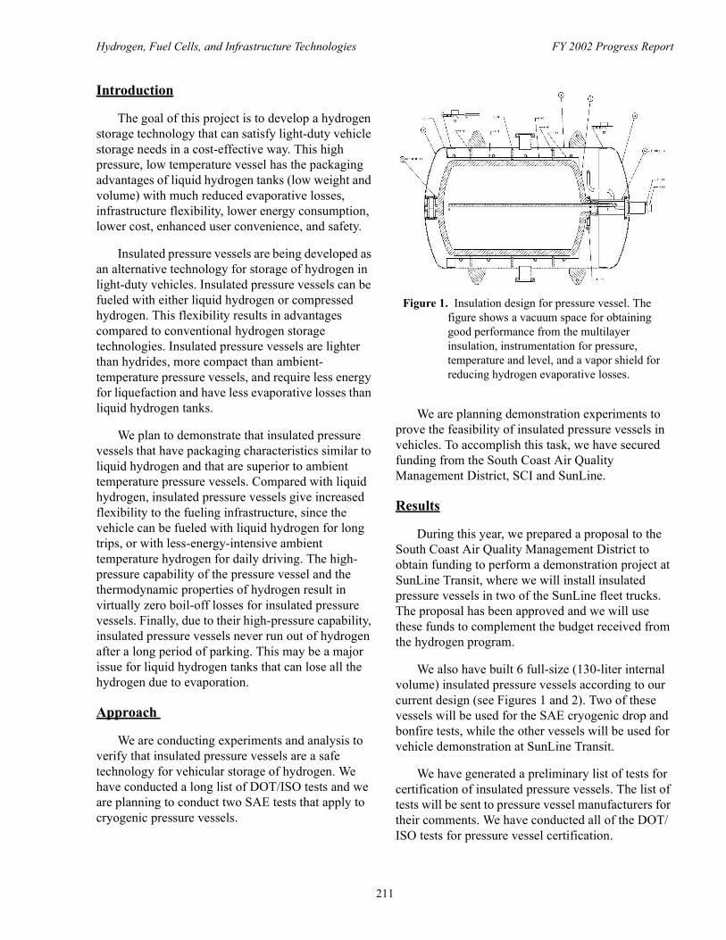
The goal of this project is to develop a hydrogen storage technology that can satisfy light-duty vehicle storage needs in a cost-effective way. This high pressure, low temperature vessel has the packaging advantages of liquid hydrogen tanks (low weight and volume) with much reduced evaporative losses, infrastructure flexibility, lower energy consumption, lower cost, enhanced user convenience, and safety.
Insulated pressure vessels are being developed as an alternative technology for storage of hydrogen in light-duty vehicles. Insulated pressure vessels can be fueled with either liquid hydrogen or compressed hydrogen. This flexibility results in advantages compared to conventional hydrogen storage technologies. Insulated pressure vessels are lighter than hydrides, more compact than ambient-temperature pressure vessels, and require less energy for liquefaction and have less evaporative losses than liquid hydrogen tanks.
We plan to demonstrate that insulated pressure vessels that have packaging characteristics similar to liquid hydrogen and that are superior to ambient temperature pressure vessels. Compared with liquid hydrogen, insulated pressure vessels give increased flexibility to the fueling infrastructure, since the vehicle can be fueled with liquid hydrogen for long trips, or with less-energy-intensive ambient temperature hydrogen for daily driving. The high-pressure capability of the pressure vessel and the thermodynamic properties of hydrogen result in virtually zero boil-off losses for insulated pressure vessels. Finally, due to their high-pressure capability, insulated pressure vessels never run out of hydrogen after a long period of parking. This may be a major issue for liquid hydrogen tanks that can lose all the hydrogen due to evaporation.
Approach
We are conducting experiments and analysis to verify that insulated pressure vessels are a safe technology for vehicular storage of hydrogen. We have conducted a long list of DOT/ISO tests and we are planning to conduct two SAE tests that apply to cryogenic pressure vessels.
We are planning demonstration experiments to prove the feasibility of insulated pressure vessels in vehicles. To accomplish this task, we have secured funding from the South Coast Air Quality Management District, SCI and SunLine.
Results
During this year, we prepared a proposal to the South Coast Air Quality Management District to obtain funding to perform a demonstration project at SunLine Transit, where we will install insulated pressure vessels in two of the SunLine fleet trucks. The proposal has been approved and we will use these funds to complement the budget received from the hydrogen program.
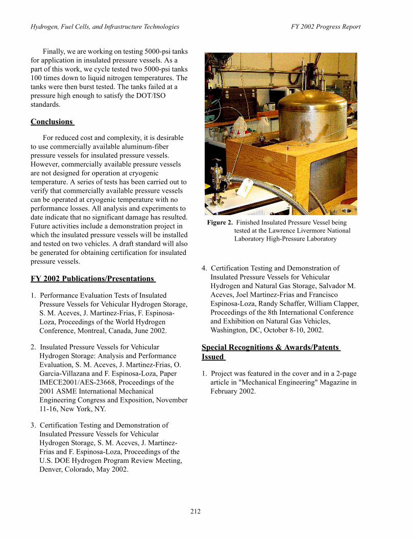
We also have built 6 full-size (130-liter internal volume) insulated pressure vessels according to our current design (see Figures 1 and 2). Two of these vessels will be used for the SAE cryogenic drop and bonfire tests, while the other vessels will be used for vehicle demonstration at SunLine Transit.
We have generated a preliminary list of tests for certification of insulated pressure vessels. The list of tests will be sent to pressure vessel manufacturers for their comments. We have conducted all of the DOT/ISO tests for pressure vessel certification.
Figure 1. Insulation design for pressure vessel. The figure shows a vacuum space for obtaining good performance from the multilayer insulation, instrumentation for pressure, temperature and level, and a vapor shield for reducing hydrogen evaporative losses.
211
Hydrogen, Fuel Cells, and Infrastructure Technologies FY 2002 Progress Report
Finally, we are working on testing 5000-psi tanks for application in insulated pressure vessels. As a part of this work, we cycle tested two 5000-psi tanks 100 times down to liquid nitrogen temperatures. The tanks were then burst tested. The tanks failed at a pressure high enough to satisfy the DOT/ISO standards.
Conclusions
For reduced cost and complexity, it is desirable to use commercially available aluminum-fiber pressure vessels for insulated pressure vessels. However, commercially available pressure vessels are not designed for operation at cryogenic temperature. A series of tests has been carried out to verify that commercially available pressure vessels can be operated at cryogenic temperature with no performance losses. All analysis and experiments to date indicate that no significant damage has resulted. Future activities include a demonstration project in which the insulated pressure vessels will be installed and tested on two vehicles. A draft standard will also be generated for obtaining certification for insulated pressure vessels.
FY 2002 Publications/Presentations
1. Performance Evaluation Tests of Insulated Pressure Vessels for Vehicular Hydrogen Storage, S. M. Aceves, J. Martinez-Frias, F. Espinosa-Loza, Proceedings of the World Hydrogen Conference, Montreal, Canada, June 2002.
2. Insulated Pressure Vessels for Vehicular Hydrogen Storage: Analysis and Performance Evaluation, S. M. Aceves, J. Martinez-Frias, O. Garcia-Villazana and F. Espinosa-Loza, Paper IMECE2001/AES-23668, Proceedings of the 2001 ASME International Mechanical Engineering Congress and Exposition, November 11-16, New York, NY.
3. Certification Testing and Demonstration of Insulated Pressure Vessels for Vehicular Hydrogen Storage, S. M. Aceves, J. Martinez-Frias and F. Espinosa-Loza, Proceedings of the U.S. DOE Hydrogen Program Review Meeting, Denver, Colorado, May 2002.
4. Certification Testing and Demonstration of Insulated Pressure Vessels for Vehicular Hydrogen and Natural Gas Storage, Salvador M. Aceves, Joel Martinez-Frias and Francisco Espinosa-Loza, Randy Schaffer, William Clapper, Proceedings of the 8th International Conference and Exhibition on Natural Gas Vehicles, Washington, DC, October 8-10, 2002.
Special Recognitions & Awards/Patents Issued
1. Project was featured in the cover and in a 2-page article in "Mechanical Engineering" Magazine in February 2002.
Figure 2. Finished Insulated Pressure Vessel being tested at the Lawrence Livermore National Laboratory High-Pressure Laboratory
212

Hydrogen, Fuel Cells, and Infrastructure Technologies FY 2002 Progress Report
III.A.4 Advanced Thermal Hydrogen Compression
David H. DaCosta (Primary Contact), Mark GolbenErgenics, Inc.373 Margaret King Ave.Ringwood, NJ 07456(973) 728-8815, fax: (973) 728-8864, e-mail: [email protected]
DOE Technology Development Manager: Lucito Cataquiz(202) 586-0729, fax: (202) 586-9811, e-mail: [email protected]
Objectives • Develop a hydride thermal hydrogen compressor that operates in conjunction with advanced hydrogen
production technologies and improves the efficiency and economics of the compression process.• Determine to what extent the hydride compression process can perform the dual function of
compression with purification, to remove impurities that adversely affect fuel cells.
Approach• Construct a single stage hydride compressor that employs miniature hydride heat exchangers and three
purification technologies (passive purification for water vapor and diatomic oxygen [O2], inert gas purification, and elevated temperature desorption for carbon monoxide [CO] and carbon dioxide [CO2]).
• Test the compressor on impure hydrogen streams to determine threshold contamination levels (levels at which compressor performance is affected) for water (H2O), O2, CO, and methane (CH4).
• Investigate compressor capabilities to perform the dual function of compression with purification for impurities that adversely affect fuel cell operation (CO and diatomic nitrogen [N2]).
• Engineer and test hydride alloys suitable for long term operation at high pressures over 5,000 pounds per square inch gauge (psig).
• Validate the entire compressor process in a multi-stage, pilot scale system.
Accomplishments • Demonstrated operation over 5,000 psig with hydride alloys from two separate "families," providing
versatility to meet application-specific needs.• Modified design operating conditions to increase efficiency, reduce energy consumption and reduce
complexity, with a corresponding economic improvement via lower capital and operating costs.• Engineered hydride alloys that can endure cycling at elevated temperatures without damage.
Future Directions • Complete construction of a single stage hydride compressor and compressor test stand. The
compressor includes hydrogen purification capabilities and the test stand includes fast response, continuous impurity monitors for the gathering of real-time operating information.
• Quantify the hydride compressor's tolerance to impurities in tests occuring in the Fall of 2002. • Validate the entire thermal compression process in a pilot scale system that includes purification
provisions and boosts hydrogen pressure to over 5,000 psig. The flow rate capability of the pilot-scale system will be similar to that required for overnight refueling of a hydrogen fuel cell automobile.
213
Hydrogen, Fuel Cells, and Infrastructure Technologies FY 2002 Progress Report
• Evaluate the commercial viability of the hydride compression process compared to existing mechanical compression and hydrogen purification technologies.
• Following a successful conclusion to this portion of the project, build and field demonstrate a full-scale compressor prototype sized for a hydrogen vehicle refueling station, and compare side-by-side with a mechanical compressor.
Introduction
Ergenics is investigating the application of its novel hydride hydrogen compression process to hydrogen produced from renewable resources. Hydride hydrogen compressors have offered significant operational and economic advantages over traditional mechanical compressors when the hydrogen is pure and flow rates are relatively low. However, hydrogen produced from renewable resources can contain impurities that might damage a hydride compressor and, if hydride compressors are to play a major role as hydrogen becomes an increasingly important part of America's energy supply, increased flow rate capabilities must be economical.
The primary focus of this project is to develop methods that allow hydride alloys to absorb non-pure hydrogen streams likely to result from renewable hydrogen production processes (DaCosta 2000). Three hydrogen purification techniques have been identified and will be tested during the fall of 2002. Increased flow capability will be accomplished by using miniature hydride heat exchangers (Golben 2001).
During the course of hydride compressor development, a number of additional insights have been gained regarding requirements for commercial hydride compressor viability. These insights are important for the overall success of the project and have been included in the project scope:
• Compression with purification may mitigate fuel cell degradation from CO. If the purification techniques used to protect the compressor's hydride alloys can be used to eliminate CO from hydrogen streams, alternative methods of extending fuel cell life may be unnecessary. A secondary benefit would be to remove impurities that damage the new hydrogen storage media now under development, such as sodium aluminum hydride and carbon nanotubes.
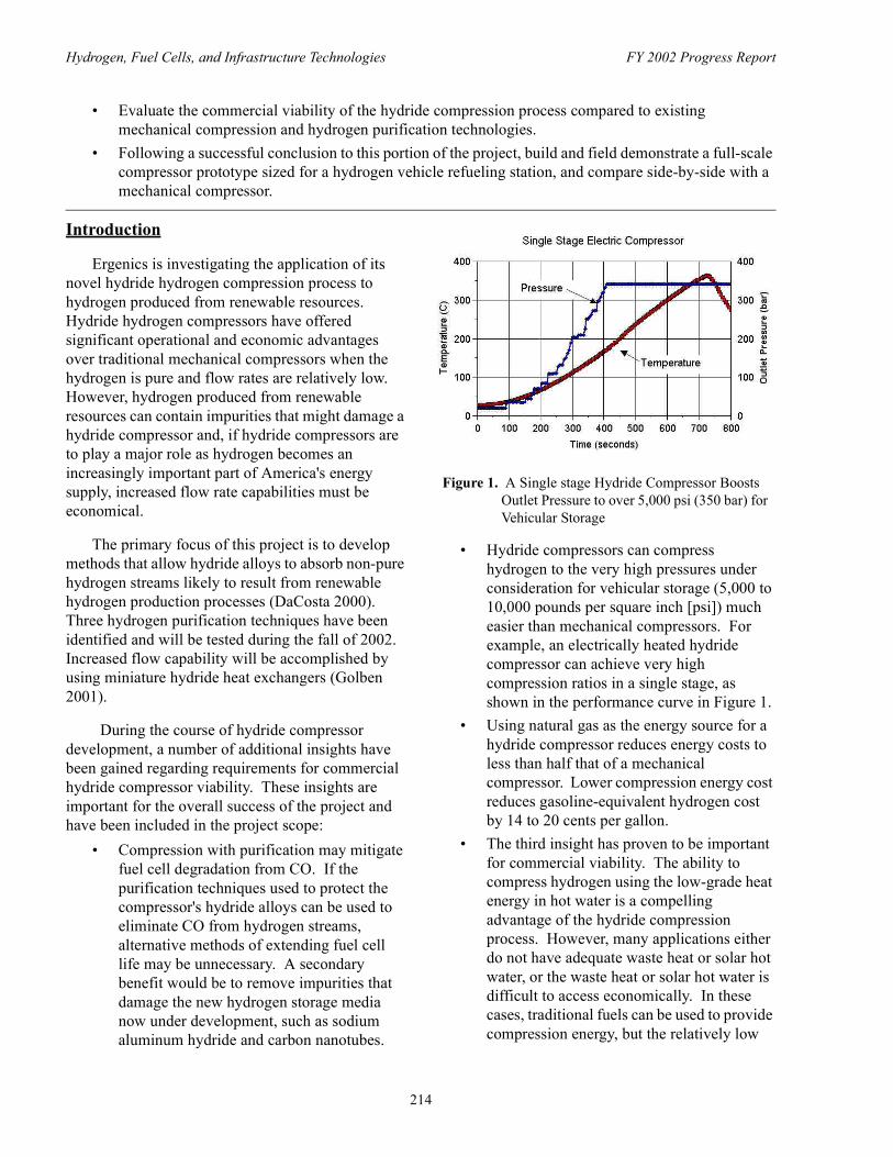
• Hydride compressors can compress hydrogen to the very high pressures under consideration for vehicular storage (5,000 to 10,000 pounds per square inch [psi]) much easier than mechanical compressors. For example, an electrically heated hydride compressor can achieve very high compression ratios in a single stage, as shown in the performance curve in Figure 1.
• Using natural gas as the energy source for a hydride compressor reduces energy costs to less than half that of a mechanical compressor. Lower compression energy cost reduces gasoline-equivalent hydrogen cost by 14 to 20 cents per gallon.
• The third insight has proven to be important for commercial viability. The ability to compress hydrogen using the low-grade heat energy in hot water is a compelling advantage of the hydride compression process. However, many applications either do not have adequate waste heat or solar hot water, or the waste heat or solar hot water is difficult to access economically. In these cases, traditional fuels can be used to provide compression energy, but the relatively low
Figure 1. A Single stage Hydride Compressor Boosts Outlet Pressure to over 5,000 psi (350 bar) for Vehicular Storage
214

Hydrogen, Fuel Cells, and Infrastructure Technologies FY 2002 Progress Report
operating efficiency of the hydride compression process must be increased by using higher temperatures. A new class of hydride alloys that will perform the compression function at elevated temperatures have been identified.
Approach
The hydride compressor is a form of "heat engine" based on the Carnot cycle. Its energy efficiency is about 50% of Carnot efficiency. Carnot efficiency is based on the temperature difference between the hot energy source and the cold heat sink. Efficiency plotted as a function of hot water (energy source) temperature appears in Figure 2.
Waste heat is usually available in the 80 to 90oC range. With a 30oC cooling water temperature, Carnot efficiency is from 13 to 16 percent and hydride compressor efficiency is from 4½ to 6½ percent. If waste heat is free, cycle economics can endure this level of efficiency.
By using a traditional form of heat energy, such as natural gas, cycle economics will benefit from an increase in hot water temperature. Using a heat transfer fluid from a gas fired heater at 130oC, Carnot efficiency is almost 25 percent, and hydride compressor efficiency increases to 15 percent. While 15 percent is about 1/2 that for a mechanical compressor, electricity is about 6 times costlier than natural gas, so the hydride compressor will enjoy a 67% lower energy cost. A simplified schematic of a natural gas powered hydride compressor appears in Figure 3.
An added benefit of higher temperature operation is a substantial reduction in the number of stages needed for a given compression ratio. Operation at 130oC in lieu of 90oC cuts by half the number of stages, with an associated reduction in system complexity, size and capital cost.
Unfortunately, when hydride alloys traditionally used for compressors are cycled at temperatures over 100oC, their performance can deteriorate through a process termed "disproportionation." In relatively few cycles, reversible hydrogen absorption capacity is lost, which would cause a hydride compressor to stop working.
Ergenics pioneered the development of high temperature, disproportionation resistant alloys in 1995, while applying a hydride heat storage system to heat an automotive catalytic converter when the car was started. A hydride heater bed was placed in the exhaust pipe between the exhaust manifold and the catalytic converter. When activated, the heater bed temperature would increase from ambient to 400oC in a few seconds. The bed would be heated to over 500oC during normal driving. The alloy used in the heater bed had to endure these high temperatures for 25,000 start cycles and over the time it takes to travel 100,000 miles. Ergenics has extended its
Figure 2. Increasing Hot Water Temperature Increases Compressor Efficiency
Figure 3. Simplified Schematic of a Natural Gas Powered Hydride Thermal Hydrogen Compressor
215

Hydrogen, Fuel Cells, and Infrastructure Technologies FY 2002 Progress Report
original disproportionation-proof alloy development to the search for compressor alloys that can survive elevated temperatures.
Starting with the alloy family used in the catalytic converter heater, Ergenics modified alloy formulations to adjust the pressure-temperature performance. A correlation was developed between the formulations and pressure-temperature performance to permit the engineering of alloys appropriate for the different pressure stages in a hydride compressor. The alloys were then tested for resistance to disproportionation.
Results
During its original high temperature alloy development work in the mid 1990's, Ergenics developed a "Soak Test" procedure to screen alloy candidates. An alloy sample is placed within a test reactor vessel and is fully hydrided at high pressure. The test vessel is then held at high temperature for an extended duration to try to induce disproportionation. Pressure is monitored during the test. The temperature is high enough that a small amount of hydrogen is lost via diffusion through the reactor vessel wall. This diffusion loss is manifested by a small pressure decrease during the test. A pressure decrease in excess of the amount anticipated for diffusion may indicate alloy disproportionation.
The test reactor is subsequently weighed to rule out whether pressure loss not due to diffusion might be attributed to leakage. Finally, the sample is refilled with hydrogen to ascertain cycle-ability.
Figures 4 and 5 show the soak test results for two alloy candidates, one that experienced performance loss (Figure 4) and one with a new formulation that did not (Figure 5).
Conclusions
Increasing the heating fluid temperature of a hydride "thermal" hydrogen compressor from 80oC to 130oC more than doubles efficiency while reducing system complexity, size and cost. If natural gas is available as the heating source, energy costs can be three times lower than for an electric-motor-driven mechanical compressor.
Disproportionation-proof alloys that will survive elevated temperature operation have been engineered.
References
1. DaCosta, David H. 2000. "Advanced Thermal Hydrogen Compression." In Proceedings of the 2000 U.S. DOE Hydrogen Program Review, 720-727. San Ramon, CA: NREL/CP-570-28890.
Figure 4. Soak Test Results Showing Alloy Disproportionation at Elevated Temperatures
Figure 5. Soak Test Results for an Alloy that is Stable at Elevated Temperatures
216

Hydrogen, Fuel Cells, and Infrastructure Technologies FY 2002 Progress Report
2. Golben, M., DaCosta, D.H. 2001. "Advanced Thermal Hydrogen Compression." In Proceedings of the 2001 U.S. DOE Hydrogen Program Review, Baltimore, MD: NREL/CP-570-30535.
FY 2002 Publications/Presentations
1. D. DaCosta, M. Golben. "Disproportionation Resistant Alloy Development for Hydride Hydrogen Compression", Proceedings 2002 U.S. Department of Energy Hydrogen Program Annual Review Meeting, Golden, May 6-8, 2002, NREL.
2. D. DaCosta, M. Golben, D.C. Tragna. "Metal Hydride Thermal Hydrogen Compression", Proceedings 14th World Hydrogen Energy Conference, Montreal, June 9-13, 2002.
3. D. DaCosta, M. Golben. "Thermal Hydrogen Compression with Purification", International Energy Agency Hydrogen Implementing Agreement, Task 17 - Solid and Liquid State Hydrogen Storage Materials Workshop, Seattle, WA, February 21-22, 2002.
217

Hydrogen, Fuel Cells, and Infrastructure Technologies FY 2002 Progress Report
III.A.5 Development of a Compressed Hydrogen Gas Integrated Storage System for Fuel Cell Vehicles
Mr. John Wozniak (Primary Contact)Johns Hopkins University Applied Physics Laboratory11100 Johns Hopkins RoadLaurel, Maryland 20723-6099(240) 228-5744, fax: (240) 228-5512, e-mail: [email protected]
DOE Technology Development Manager: Lucito Cataquiz(202) 586-0729, fax: (202) 586-9811, e-mail: [email protected]
Main Subcontractor: General Dynamics Armament & Technical Products (GDATP), Lincoln, Nebraska
Objectives• Advance the technology elements required to develop a semi-conformal, Compressed Hydrogen Gas
Integrated Storage System (CH2-ISS) for light-duty fuel cell vehicles (FCVs)• Conduct engineering research to:
- Develop materials and treatments to reduce hydrogen gas permeation through tank liners- Develop an optimized carbon fiber/epoxy resin tank overwrap- Determine alternative designs and materials for constructing the unifying elements of the integrated
storage system
Approach • Develop baseline CH2-ISS design consistent with notional FCV packaging and driving range
requirements• Develop tank liner surface treatments and measure hydrogen gas permeation• Build and performance test all-carbon overwrap tanks with alternative toughened epoxy resin systems• Explore with manufacturers alternative materials and means for low-cost production of the ISS outer
shell and unitary gas control system• Develop a roadmap identifying the steps needed to prototype the CH2-ISS and safety certify the
container for FCV applications
Accomplishments • Developed computer-aided drafting (CAD) models of alternative ways to construct the CH2-ISS • Developed a process for surface treating the high density polyethylene (HDPE) tank liner to reduce
hydrogen gas permeation• Measured gas permeation and met allowable with acceptable margin• Built a series of all-carbon overwrap hydrogen gas tanks with alternative toughened epoxy resin
systems and conducted burst and gunfire tests• Established an all-carbon overwrap design that passes gunfire test at the minimum factor of safety
(2.25)
218

Hydrogen, Fuel Cells, and Infrastructure Technologies FY 2002 Progress Report
• Conducted a manufacturing trade study of alternative means and materials for fabricating the CH2-ISS outer protective shell
• Designed two alternative means for building the CH2-ISS unitary gas control unit
Future Directions• Continue to develop liner materials and processing (metalization and surface coatings) to further
reduce hydrogen gas permeation• Optimize tank overwrap toughened resin system with respect to cost, minimizing impact on service
temperature and tank manufacturability• Conduct series of tests to quantity the performance of the CH2-ISS tank design• Conduct flammability and impact tests on alternative CH2-ISS outer shell materials; select optimum
for prototype build• Detail design and prototype build the unitary gas control system
Introduction
FCVs are identified by the DOE, and virtually every major automaker, as a potential solution to problems of air quality and dependency on foreign fuel. Fuel cells produce electricity by combining hydrogen with oxygen from air to produce electrical power and give off only water vapor. The onboard storage of hydrogen fuel can consist of compressed hydrogen gas (cH2) systems, cryogenic liquid hydrogen tanks or chemical or metal hydride storage systems. Another source of hydrogen is derived from gasoline, diesel, methane, or natural gas by using an onboard reformer. Of the many means of carrying hydrogen, cH2 is one of the most attractive technologies because of fast refueling times, unlimited refueling cycles, ease of low temperature startup, superior long-term stability, and true zero vehicle emissions.
The storage of cH2, however poses challenges in the areas of relatively low energy density, system cost, crashworthiness, and vehicle packaging. A solution to these challenges is offered by the Integrated Storage System (ISS) technology (U.S. Patent No. 6,257,360 issued July 2001) jointly developed by Johns Hopkins University Applied Physics Laboratory (JHU/APL) and General Dynamic Armaments and Technical Products (GDATP) (formerly Lincoln Composites). Under DOE Cooperative Agreement DE-FC36-01G011003 the ISS technology is being advanced to support development of a 5,000 pounds per square inch (psi)
hydrogen gas service pressure, 5% or better gas mass fraction system that meets safety, vehicle packaging, and production cost objectives.
Technical Approach
ISS uses Type IV all-composite tanks constructed with a high-density polyethylene (HDPE) thermoplastic liner structurally overwrapped with carbon fiber and epoxy resin. The tanks are encapsulated within a high-strength outer shell unitizing the individual cylinders into a single container and providing protection from environmental exposure. Additional physical protection of the tanks is provided by urethane foam surrounding the tank dome region (location of highest stress concentration during impact). A unitized gas control module is incorporated into the ISS package and provides all necessary gas flow control and safety features. Figure 1 is a CAD image of the CH2-ISS design. The objective of this project is to advance the technologies needed to support development and safety certification of a CH2-ISS.
There are four specific tasks: (1) HDPE treatment and development of alternative tank liner materials for hydrogen gas permeation reduction; (2) enhancing epoxy resin toughness to improve the tank carbon fiber overwrap performance; (3) materials and process evaluation for manufacturing the ISS protective shell; and (4) engineering an optimized unitary gas control module. An additional task (5) is the formulation of a roadmap for prototyping and
219

Hydrogen, Fuel Cells, and Infrastructure Technologies FY 2002 Progress Report
safety certifying the CH2-ISS for potential mass production.
Result
Task (1) ISS uses Type IV high-pressure gas storage tanks using a HDPE thermoplastic liner, (see Figure 2) overwrapped with carbon fiber and epoxy resin. The liner serves as a permeation barrier, mechanical interface to aluminum bosses, and a stable mandrel for the filament winding process. The main focus of the permeation task has been to quantify and control the hydrogen gas permeation rate through the HDPE. In FY02 a low-cost, proprietary surface treatment process was developed to reduce the hydrogen permeation. The tests were conducted on both the untreated and surface treated
HDPE liners. Testing at 5,000 psi indicated a permeation rate of about 0.8 standard cubic centimeters per hour per liter (scc/hr/l) for the untreated HDPE and about 0.2 scc/hr/l for the treated. The current draft standard (e.g. ISO/DIS 15869) allows a permeation rate of 1.0 scc/hr/l. Additional work was done to develop a process for applying a coating to the surface of the HDPE liner. The permeation rate through the propriety surface coating has yet to be quantified.
Task (2) In FY02, a series of Type IV, all-carbon (T-700) tanks were designed, fabricated and performance tested. The objective was to develop the technology to construct small-diameter tanks for an operating pressure of 5,000 psi that would pass the critical gunfire test at the minimum allowable burst factor of safety (FOS) of 2.25. The overwrap technology investigation involved using winding patterns that maximize interspersion between helical and hoop layers. In addition, series of resin formulations were evaluated to assess their impact on tank gunfire performance. The brittle nature of structural epoxy resins is suspected of contributing to localized delaminating of the overwrap, resulting in catastrophic tank rupture under gunfire testing. Two toughening agents, polyether sulphone and amine-terminated butadiene acrylonitrile, formulated into GDATP's standard resin, in combination with the enhanced winding pattern, led to successful gunfire tests for an all-carbon fiber, 2.25 FOS tank construction. Based on this work, a preliminary tank design was developed (see Figure 3) for the CH2-ISS application.
Task (3) The ISS uses a high-strength, lightweight shell/cover in conjunction with flexible
Figure 1. Assembly View of the CH2-ISS
Figure 2. High Density Polyethylene Liner
Figure 3. CH2-ISS Tank Preliminary Design
220

Hydrogen, Fuel Cells, and Infrastructure Technologies FY 2002 Progress Report
urethane impact-absorbing foam to encapsulate and protect the individual tanks into a single unitized container. In FY02, the shell technology work focused on identifying a manufacturing process and materials that result in the optimum combination of component strength, toughness, weight, tooling and part cost, trimming and assembly cost, and chemical resistance. Two Pro/ENGINEER CAD designs were developed to support an evaluation of alternative means for high-volume production of the CH2-ISS outer shell and gas control cover. Working with industry, a trade study was performed that examined a number of materials/processes and resulted in a downselect of two alternatives for further investigation - fabrication via (1) compression molding with Sheet Molding Compound (SMC) and (2) preform fabrication using Directed Fiber Preform combined with Structural Reaction Injection Molding.
Task (4) The ISS is assembled as a single, inseparable container, requiring only one manual service valve, one solenoid, and one thermally activated pressure relief device, all incorporated into a gas control module (see Figure 4). The added cost and complexity of redundant components when using multiple, separable cH2 tanks is avoided by this approach. The gas control system is safeguarded from physical damage with impact absorbing foam
CH2-ISS Performance Estimate
within a high-strength protective cover. In FY02, two alternative Pro/ENGINEER CAD notional models were developed focused on a fully unitize affordable gas control module. The two designs are variants of JHU/APL's patented design "Compressed Gas Manifold" (U.S. patent # 6,321,775, dated November 27, 2001).
Task (5) The technology tasks completed in FY02 and the work needed to continue development was assembled into an overall project roadmap. The roadmap identifies out-year tasks needed to fully develop and safety-certify a CH2-ISS for potential mass production. The roadmap identifies important studies and/or subsystem developments and tests that minimize the risk of undertaking the full CH2-ISS development.
Conclusions
Substantial progress has been made in developing a high energy density, near-rectangular, safety-certified and affordable container for the onboard storage of compressed hydrogen gas for use in FCVs. The work has focused on the Integrated Storage System design, hydrogen tank permeation
Figure 4. Unitary Gas Control Module Design
Total Empty Weight 73 Kg
Service Perssure 340 bar
Total Hydrogen Capacity 4.2 Kg
Gas/Container Mass Fraction 5.7%
External Volume 266 liter
Internal Gas Volume 166 liter
Figure 5. Estimated CH2-ISS Characteristics
221

Hydrogen, Fuel Cells, and Infrastructure Technologies FY 2002 Progress Report
reduction and overwrap development, and a trade-off study of protective shell and gas control manufacturing options. The information developed has been formulated into a preliminary CH2-ISS design with performance estimated (see Figure 5). Continued component development and critical tests are proposed for FY03 which will enable future full development of a CH2-ISS and its safety certification.
FY 2002 Publications/Presentations
1. Development of a Compressed Hydrogen Gas Integrated Storage System (CH2-ISS) for Fuel Cell Vehicles- Midterm Report, ADS-02-014, April 2002
2. Development of a Compressed Hydrogen Gas Integrated Storage System (CH2-ISS) for Fuel Cell Vehicles- Peer Review Presentation CD/ROM Report, June 19, 2002
Special Recognition & Awards/Patent Issued
1. U.S. patent No. 6,418,962 entitled "Low Cost Compressed Gas Fuel Storage System", awarded July 16, 2002
222

Hydrogen, Fuel Cells, and Infrastructure Technologies FY 2002 Progress Report
III.A.6 Low Permeation Liner for Hydrogen Gas Storage Tanks
Paul A. Lessing (Primary Contact)Idaho National Engineering & Environmental Laboratory (INEEL)P.O. Box 1625Idaho Falls, ID, 83415-2218(208) 526-8776, fax: (208) 526-0690, e-mail: [email protected]
INEEL Technical Advisor: Raymond P. Anderson(208) 526-1623, fax: (208) 526-9822, e-mail: [email protected]
DOE Technology Development Manager: Lucito Cataquiz(202) 586-0729, fax: (202) 586-9811, e-mail: [email protected]
Main Subcontractor: University of California at Los Angelos, Los Angeles, CA
Objective• Develop a polymer liner that greatly limits hydrogen losses from commercial, light-weight, composite,
high-pressure hydrogen tanks.
Approach• Select and fabricate polymeric materials with the necessary electron and proton conducting properties• Fabricate a "bench-top" model of a tri-layer, electrochemically-active protection device that greatly
reduces hydrogen permeation through polymer "substrates"• Demonstrate the successful functioning of the bench-top device • Demonstrate a successful prototype of an active, electrochemical hydrogen barrier system within a
high-pressure, polymer-lined, composite hydrogen storage tank
Accomplishments • Invented a unique concept for an electrochemically active, tri-layer device to prevent hydrogen
permeation through a polymeric tank liner • Negotiated a cooperative agreement with a high-pressure hydrogen tank manufacturer• Negotiated a statement of work for a major subcontract with a university that is actively engaged in
research on conductive polymer compositions
Future Directions • Select the proper materials of construction• Fabricate tri-layer coatings having the necessary structural and electrochemical properties• Experimentally verify that operation of the barrier provides hydrogenation/permeation protection
223

Hydrogen, Fuel Cells, and Infrastructure Technologies FY 2002 Progress Report
Introduction
State-of-the-art high-pressure gas storage tanks consist of an inner liner, made from a polymer such as cross-linked polyethylene or nylon, overlaid with a continuous graphite fiber/epoxy reinforcement layer. These tanks have successfully stored high-pressure methane gas. It is desired to extend the application of this type of tank to high-pressure hydrogen. However, hydrogen has a significantly higher permeability rate through these polymer liners than does methane. Permeation leads to a gradual loss of hydrogen pressure, and the hydrogen is thought to damage and weaken the reinforcement layer.
This project was recently begun to develop a hydrogen diffusion barrier that can be applied to the interior of the polymer liner. To be effective, the barrier must have the following attributes: (1) low permeability of hydrogen, (2) good adherence to the polymer liner, (3) stiffness (modulus) of the coating that matches the underlying polymer to avoid cracking when the tank is pressurized, (4) an application method that allows for coating inside a tank with a narrow neck and results in hermetic (gas-tight) coatings that are devoid of pin-holes, and (5) a material and coating method that does not appreciably add to the overall cost or weight of the tank.
Approach
An electrochemically "active" hydrogen barrier, fabricated from polymers, will be developed. A schematic of this barrier is shown in Figure 1.
The development plan includes the following:• The barrier is to be constructed of three
layers of polymers consisting of a proton-conducting electrolyte (electronic insulator) sandwiched between electronically conductive polymer electrodes. Candidate polymer compositions will be selected based upon existing knowledge. If this knowledge is not sufficient, new or modified compositions will be developed. Appropriate catalyst materials will be added at the electrolyte/electrode interfaces.
• The methods to manufacture the layers will be adapted from existing techniques or developed during the project. This could include dip coating or spraying of monomers followed by polymerization. Other possibilities will be explored and successful manufacturing technologies will be developed.
• The device is designed as a galvanic-type device that functions to prevent hydrogen permeation through application of a small direct current (dc) voltage using small currents. Methods to provide attachment of the dc voltage will be developed.
The hydrogen partial pressure established by the voltage is extremely low at the underlying polymer interface. The hydrogen partial pressure can be calculated using the Nernst equation (relates the voltage of a cell to its thermodynamic properties), as shown in Figure 1. An appropriate level of voltage will be calculated and experimentally verified.
Results
This project has only recently begun, having been funded late in FY 2002. A patent application was drafted and submitted to the U.S. Patent Office. The application covers the basic concept, designs, and possible manufacturing methods. An initial literature search was conducted for the polymeric
Figure 1. Schematic Showing Tri-layer Hydrogen Barrier Concept
224

Hydrogen, Fuel Cells, and Infrastructure Technologies FY 2002 Progress Report
materials that are intended to comprise the 3 layers of the electrochemically active coating.
A Cooperative Research and Development Agreement was negotiated between an industrial partner that manufacturers composite, high-pressure, INEEL (Bechtel BWXT Idaho). Additionally, a statement of work was negotiated with a university subcontractor (University of California at Los Angeles).
Conclusions
The project is just beginning, so conclusions are not yet available.
Patent
1. U.S. Patent Application: Paul A. Lessing, "Polymeric Hydrogen Diffusion Barrier, High-Pressure Storage Tank so Equipped, Method of Fabricating a Storage Tank, and Method of Preventing Hydrogen Diffusion", September, 2002.
225

Hydrogen, Fuel Cells, and Infrastructure Technologies FY 2002 Progress Report
III.B Carbon Materials
III.B.1 Hydrogen Storage in Carbon Single-Wall Nanotubes
A.C. Dillon, K.E.H. Gilbert, P.A. Parilla, J.L. Alleman, G.L. Hornyak, K.M. Jones, and M.J. Heben (Primary Contact) National Renewable Energy Laboratory1617 Cole Blvd.Golden, CO 80401(303) 384-6641, fax: (303) 384-6655, e-mail: [email protected]
DOE Technology Development Manager: JoAnn Milliken(202) 586-2480, fax: (202) 586-9811, e-mail: [email protected]
Objectives• Determine the extent to which carbon single-wall nanotubes (SWNTs) can reversibly store hydrogen.• Discover the mechanism of hydrogen storage in SWNTs.• Develop simple, reproducible, and potentially scalable processes for producing SWNTs.
Approach• Decouple the two steps in the ultrasonication process used to activate SWNTs for hydrogen storage,
i.e., cutting and metal hydride introduction, to improve process control and to determine the relative contribution of each to the hydrogen storage capacity.
• Develop new methods for cutting SWNTs that avoid the introduction of the metal alloy and develop separate processes to introduce metal hydrides to the SWNTs in a controlled manner.
• Develop techniques to determine and measure the key characteristics of SWNTs that yield high hydrogen storage capacities.
Accomplishments• Developed two different dry cutting methods for cutting SWNTs, which are in the process of being
patented. Neither process involves sonication and therefore, cut samples that are free from metals can be produced.
• Improved control over pulsed laser synthesis of SWNTs, producing samples with hydrogen storage capacities of 4 weight percent (wt%).
• Developed a Raman analysis technique that can be used to characterize the purity and defects in SWNT materials. Raman analysis can also be used to determine the degree of cutting in bulk SWNT samples.
Future Directions• Correlate the degree of SWNT cutting with hydrogen storage capacities in order to understand the
hydrogen adsorption mechanism more completely.• Probe possible adsorption pathways in order to explain why only specific nanotubes appear to be
optimal for hydrogen storage applications.
226

Hydrogen, Fuel Cells, and Infrastructure Technologies FY 2002 Progress Report
• Develop a method for the controlled incorporation of metal catalyst particles of discrete sizes and in specific locations so that SWNT hydrogen storage capacities may be reproducibly optimized.
• Optimize the purity, production rate, diameter, and chirality of the laser-generated SWNT samples to reliably achieve 6-7 wt% hydrogen storage.
Introduction
Hydrogen storage technology must be significantly advanced in performance and cost effectiveness if the U.S. is to establish a hydrogen-based transportation system. Gas-on-solid adsorption is an inherently safe and potentially high energy density hydrogen storage method that could prove to be more energy efficient than other hydrogen storage methods under evaluation, such as chemical or metal hydrides and compressed gas storage. Carbon single-wall nanotubes (SWNTs) and other nanostrucured carbon materials are being evaluated for this application. The long-term goal is to scale up production of optimized SWNT materials to enable efficient adsorption of hydrogen at ambient temperature and pressure and at system energy densities specified by the DOE Hydrogen, Fuel Cells, and Infrastructure Technologies Program (6.5 wt% and 62 kg/m3).
Approach
Currently, the high-power ultrasonication method used to activate SWNTs for hydrogen storage simultaneously cuts purified SWNTs into shorter segments and introduces a metal hydride alloy (TiAl0.1V0.04) into the SWNTs. However, the sonication process does not provide for detailed or independent control of either cutting or metal incorporation. Differing degrees of cutting, amounts of metal, and metal particle sizes are found in processed samples even when identical sonication parameters (sonication time, sonication power, acid concentration, hydrodynamics, etc.) are employed. This lack of process control leads to variability in the performance of the final SWNT materials, which show hydrogen storage capacities on the tube fraction ranging from 0 to 8 wt%.
This research project is focusing on increasing control of the process used to activate the SWNTs for hydrogen, as well as developing reliable methods to determine and control the characteristics necessary
for optimizing the hydrogen storage capacity of SWNTs.
Results
Control of Laser-Production of Tailored SWNT Size and Type Distributions
Currently, SWNT materials are synthesized using a laser vaporization process. Samples with hydrogen storage capacities of ~7 wt% have been produced in a free running Nd:YAG laser (1064 nanometer [nm]) synthesis. Initial samples made with the Alexandrite laser (755 nm) showed less than 1 wt% storage. Multi-colored Raman measurements show that the Alexandrite laser was producing SWNTs that differ in diameter and chirality from those produced by the Nd:YAG laser. Past research on laser-generated SWNTs established that as the laser peak pulse power increases, SWNT diameter distributions shift to smaller diameters and SWNT chirality distributions result in semiconducting (rather than metallic) material properties. Using these two findings together, researchers have produced nanotube diameter and type distributions with the Alexandrite laser that are nearly identical to the Nd:YAG laser, as illustrated in Figure 1. Subsequent syntheses with the same peak power showed that the production of this SWNT size and type distribution is highly reproducible. With better control over SWNT production, samples with hydrogen storage capacities of 4 wt% have been fabricated with the Alexandrite laser.
Poor Repeatability of High Hydrogen Adsorption Capacities
The hydride alloy (TiAl0.1V0.04) accounts for a portion of the hydrogen storage capacity of the alloy/nanotube composite material that is formed in the ultrasonication process. Figure 2 displays a plot of hydrogen storage capacity versus alloy metal content for numerous purified SWNT samples that were treated with the ultrasonic probe process. About one-
227

Hydrogen, Fuel Cells, and Infrastructure Technologies FY 2002 Progress Report
half of the samples show hydrogen adsorption capacities that are too high to be explained by the presence of the alloy alone, indicating that these SWNTs have been activated for hydrogen storage. Assuming the hydrogen storage capacity of the TiAl0.1V0.04 alloy is 2.99 wt%, the SWNTs have hydrogen storage capacities between 0-8 wt%, with ~8 wt% being a maximum value, independent of the amount of alloy present. Possible explanations for the observed variability include (1) the extent of destruction to the SWNTs caused by the ultrasonic
cutting process and (2) the size of the metal alloy particles incorporated.
Development of Controlled Cutting Method Without Metal Hydride Incorporation
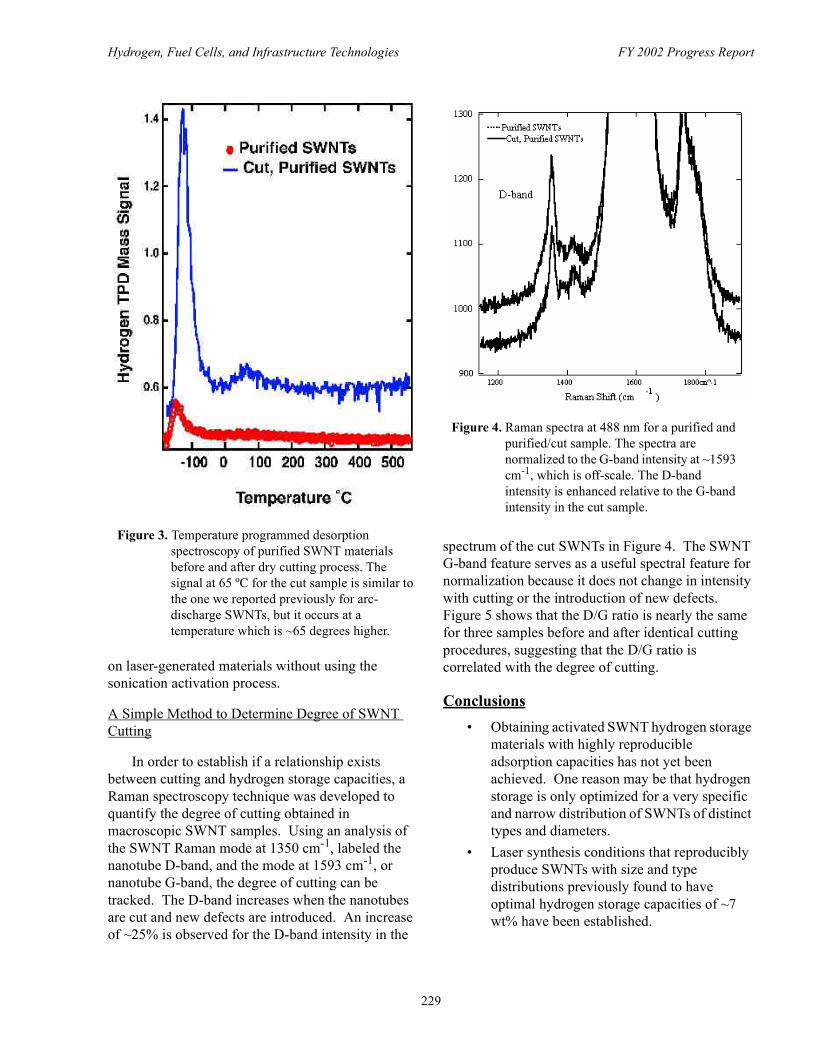
To reduce the variability in the performance of the activated SWNTs, research has focused on decoupling the cutting and metal introduction processes. Controlled cutting of carbon single-wall nanotubes has been achieved via a new cutting method that does not employ ultrasonication. Transmission electron microscopy analyses and Raman spectroscopy show that significant cutting occurs without significant damage to the SWNTs. Figure 3 compares hydrogen temperature programmed desorption spectra of a purified SWNT sample and a SWNT sample cut with the new method. The spectrum of the cut sample shows an additional hydrogen desorption peak at ~65ºC, indicating the presence of hydrogen that is stabilized at ambient temperatures. This is the first time high-temperature adsorbed hydrogen has been observed
Figure 1. Raman spectra in the radial breathing mode region for a) a Nd:YAG-produced sample with a H2 adsorption capacity of ~7 wt%, and b) a sample produced with the Alexandrite laser operating with a 200 ns pulse width at a peak power of 10.5 MW/cm2. The red curves (highest curve on each figure) are for Raman excitation at 632.8 nm and show the SWNT size distribution for excited metallic and semiconducting tubes. The blue curves (lowest curve on each figure) were obtained at 488 nm and show predominantly semiconducting tubes.
Figure 2. Plot of total sample hydrogen wt% content versus metal alloy content for SWNT samples following high energy sonication in HNO3 with an ultrasonic probe. Lines are drawn as a guide to the eye to show the anticipated hydrogen storage based on metal alloy content alone.
228
Hydrogen, Fuel Cells, and Infrastructure Technologies FY 2002 Progress Report
on laser-generated materials without using the sonication activation process.
A Simple Method to Determine Degree of SWNT Cutting
In order to establish if a relationship exists between cutting and hydrogen storage capacities, a Raman spectroscopy technique was developed to quantify the degree of cutting obtained in macroscopic SWNT samples. Using an analysis of the SWNT Raman mode at 1350 cm-1, labeled the nanotube D-band, and the mode at 1593 cm-1, or nanotube G-band, the degree of cutting can be tracked. The D-band increases when the nanotubes are cut and new defects are introduced. An increase of ~25% is observed for the D-band intensity in the
spectrum of the cut SWNTs in Figure 4. The SWNT G-band feature serves as a useful spectral feature for normalization because it does not change in intensity with cutting or the introduction of new defects. Figure 5 shows that the D/G ratio is nearly the same for three samples before and after identical cutting procedures, suggesting that the D/G ratio is correlated with the degree of cutting.
Conclusions• Obtaining activated SWNT hydrogen storage
materials with highly reproducible adsorption capacities has not yet been achieved. One reason may be that hydrogen storage is only optimized for a very specific and narrow distribution of SWNTs of distinct types and diameters.
• Laser synthesis conditions that reproducibly produce SWNTs with size and type distributions previously found to have optimal hydrogen storage capacities of ~7 wt% have been established.
Figure 3. Temperature programmed desorption spectroscopy of purified SWNT materials before and after dry cutting process. The signal at 65 ºC for the cut sample is similar to the one we reported previously for arc-discharge SWNTs, but it occurs at a temperature which is ~65 degrees higher.
Figure 4. Raman spectra at 488 nm for a purified and purified/cut sample. The spectra are normalized to the G-band intensity at ~1593 cm-1, which is off-scale. The D-band intensity is enhanced relative to the G-band intensity in the cut sample.
229

Hydrogen, Fuel Cells, and Infrastructure Technologies FY 2002 Progress Report
• A new controlled dry cutting method that non-destructively cuts nanotubes without incorporating a metal hydride alloy has been developed.
• A new Raman spectroscopy-based technique that promises to allow the extent of SWNT cutting to be quantified has been developed.
FY 2002 Publications/Presentations
1. Dillon, A.C.; Gilbert, K.E.H.; Parilla, P.A.; Alleman, J.L.; Gennett, T.; Grigorian, L.; Jones, K.M.; Heben, M.J. “Hydrogen Storage in Single-Wall Carbon Nanotubes.” In Proceedings of the 14th World Hydrogen Energy Conference Montreal, Quebec, Canada, June 2002.
2. Hornyak, G.L.; Grigorian, L.; Dillon, A.C.; Parilla, P.A.; Jones, K.M.; Heben, M.J. “A Temperature Window for Chemical Vapor Decomposition Growth of Single-Wall Carbon Nanotubes.” J.Phys. Chem B 2002, 106, 2821-2825.
3. Dillon, A.C.; Parilla, P.A.; Gennett, T.; Alleman, J.L.; Jones, K.M.; Heben, M.J. “A Narrow and Defect-activated Raman D-Band in Pure Bulk Carbon Single-wall Nanotubes.” Submitted to Phys. Rev. Lett.
4. Grigorian, L.; Hornyak, G.L.; Dillon, A.C.; Parilla, P.A.; Heben, M.J. “Synthesis of All Zig-Zag Single-Wall Carbon Nanotubes by CVD.” Manuscript in preparation.
5. Maness, P.-C.; Smolinski, S.; Dillon, A.C.; Heben, M.J.; Weaver, P.F. “Characterization of the Oxygen Tolerance of a Hydrogenase Linked to a Carbon Monoxide Oxidation Pathway in Rubrivivax gelatinosus.” To appear in Appl. Env. Microbiology.
Special Recognitions & Awards/Patents Issued
1. Grigorian, L.; Hornyak, G.L.; Dillon, A.C.; Heben, M.J. “Continuous Growth of SWNTs by CVD.”
2. Dillon, A.C.; Parilla, P.A.; Heben, M.J. “Bulk Cutting of SWNTs.” In preparation.
Figure 5. The ratio of the D-band intensity to the G-band intensity for a few samples before and after cutting. The D/G intensity ratio increases by a fixed amount after the same cutting procedures were applied.
230

Hydrogen, Fuel Cells, and Infrastructure Technologies FY 2002 Progress Report
III.B.2 Doped Carbon Nanotubes for Hydrogen Storage
Ragaiy Zidan (Primary Contact)Savannah River Technology Center773-41A, Savannah River SiteAiken, South Carolina(803) 725-1726, fax: (803) 725-4129, e-mail: [email protected]
DOE Technology Development Manager: JoAnn Milliken (202) 586-2480, fax: (202) 586-9811, e-mail: [email protected]
Objectives • Develop reversible high-capacity hydrogen storage material with the following properties:
- Hydrogen capacity greater than 6 weight % - Favorable thermodynamic and kinetics suitable for transportation applications - Stable with hydriding/dehydriding cycling - Resistant to trace contaminates
Approach• Create a weak covalent bond between hydrogen and carbon by doping carbon nanotubes with metals to
manipulate the electronic structure• Produce consistent size metal dopants and structures of carbon nanotubes• Control the type and size of the tubes and clusters inside the tubes • Tune the material for hydrogen sorption to occur at desired temperatures and pressures• Conduct thermodynamic and energetic characterization on hydrogen sorption• Conduct spectroscopic characterization and elemental analysis to guide the effort
Accomplishments• Developed Dopant Encapsulation, a novel method for producing metal doped carbon nanotubes with
controlled size and structures (patent is applied for), which allows gram quantities of doped nanotubes with high purity to be produced
• Produced samples with different dopants, alloyed dopants• Preliminary hydriding and dehydriding of samples showed hydrogen uptake and release of about 1.0
by weight % (more than expected from physisorption)• Preliminary testing of cycling of hydrogen uptake and release showed consistent uptake and release
over 10 cycles
Future Directions • Continue producing nanotubes with different dopants and configurations using Dopant Encapsulation
method• Tune structure and control amount of dopants to optimize hydrogen binding energy (via achieving
dihydrogen bonding)• Conduct thermodynamic characterization of hydrogen uptake and release
231
Hydrogen, Fuel Cells, and Infrastructure Technologies FY 2002 Progress Report
• Utilize different spectroscopic methods (e.g. scanning electron microscopy [SEM], transmission electron microscopy [TEM], energy dispersive spectroscopy [EDS], etc.) to identify the type and size of nanotubes and clusters of dopants that result in a reversible high hydrogen capacity
• Tune conditions that result in a high yield of material possessing favorable characteristics such as storage capacity greater than 6 weight % hydrogen
• Perform cycling tests on material and investigate the effect of contaminants on hydrogen sorption• Coordinate research and development effort with other DOE Laboratories and organizations working
on carbon for hydrogen storage
Introduction
A major obstacle to a transition to a hydrogen economy has been the absence of a practical means for hydrogen storage. The goal of researchers has been to develop a high-density hydrogen storage system that can release hydrogen at temperatures lower than 100°C. It has been recognized that developing a suitable solid-state hydrogen storage material will be ideal for engineering a practical storage system. Carbon nanotubes represent a new direction for solid hydrogen storage, especially if these materials can be altered to store large amounts of hydrogen at room temperature. Widespread research activity into the properties and applications of the nanometer scale cylindrical carbon tubes has been reported [1-3], with much focus on the use of carbon nanotubes for hydrogen storage [4-8].
Simple mechanisms for hydrogen uptake and release involving physisorption and/or chemisorption cannot account for the unusual sorption of hydrogen by carbon nanotubes. In some cases, however, the unique nanotube structure and configurations could give rise to polarization and condensation of hydrogen inside the tubes. The research presented here is focused on modifying carbon nanotubes in an attempt to enhance and tune their hydrogen storage capabilities using metal dopants. The objective of this research has been to introduce transition metals and/or metal clusters inside the tubes that allow for hydrogen uptake and release. Establishing a relatively weak nanotube-hydrogen bond (not as weak as physisorption bond) should allow hydriding/dehydriding to occur at mild conditions of temperature and pressure. Producing consistent structures is also necessary for reliable results and reproducible data.
Approach
Introducing nano-particles (dopants) to carbon nanotubes to create a weak covalent bond has been the general approach of this work. The goal has been to establish an interaction between hydrogen and carbon nanotubes based on a weak covalent bond where the electron donation from the (σ) orbital of hydrogen to the doped tubes weakens but does not break the hydrogen-hydrogen bond [9,10]. The unique strategy of this research is not just to dope carbon nanotubes with metals, but also to control the type and size of the tubes and the encapsulated metal clusters. This allows the electron density to be manipulated and the material to be tuned for hydrogen sorption at desired temperatures and pressures. The process is intended to take advantage of the nano scale properties of the system. This research is also aimed at producing gram quantities of consistent structures and sizes. Scanning and transmission electron microscopy are used to investigate configuration of tubes and dopants and to guide the development of the materials. Thermogravimetric and thermovolumetric analyzers are used to measure and quantify hydrogen uptake and release.
Results
The synthesis of different doped carbon nanotubes has been achieved using the Dopant Encapsulation method we developed. This method was used to dope the tubes not only with metals, but also with alloyed clusters of different metals. The Dopant Encapsulation method was utilized to produce large quantities of metal doped carbon nanotubes of consistent structure (see Figures 1 and 2). A thermogravimetric system capable of operating at a wide range of temperatures was used to measure
232

Hydrogen, Fuel Cells, and Infrastructure Technologies FY 2002 Progress Report
hydrogen uptake and release. The system was enclosed in an inert atmosphere glove box to avoid contamination from water and reactive gases. Preliminary results showed consistent hydrogen uptake and release of 1% by weight. The sample was cycled 10 times without deterioration of hydrogen capacity.
Conclusions
The immediate objective of this work was to produce large quantities of carbon nanotubes with consistent structures that can be modified as needed. Therefore, a novel method for producing and controlling configuration and structure of carbon nanotubes was developed and demonstrated. The Dopant Encapsulation method enables the production of doped carbon nanotubes with transition metals and alloys that can give rise to weak covalent bonds similar to dihydrogen. The encapsulation of a metal at the tip of the tube eliminates the need for opening or cutting the tube. Preliminary results, using a thermogravimetric analyzer, showed hydrogen uptake and release of 1% by weight.
Figure 1. Shows SEM Images of Large Quantities of Nanotubes Doped with Different Metals (Gram Quantity Samples were Produced).
Figure 2. Shows the Tip of a Nanotube with Encapsulated Metal Particle
233

Hydrogen, Fuel Cells, and Infrastructure Technologies FY 2002 Progress Report
Acknowledgement
This research work was done in collaboration with Dr. Apparao M. Rao, Department of Physics, Clemson University, South Carolina.
References
1. S. Iijima, Nature, 354 (1991) 56
2. S. Iijima and T. Ichihashi Nature, 363 (1993) 603
3. D. S. Bethune, C.H. Kiang, M. S. de Vries, G. Gorman, R. Savoy, J. Vazquez and R. Beyers, Nature, 363 (1993) 605
4. A.C. Dillon, K. M. Jones, T. A. Bekkedahl, C.H. Kiang, D. S. Bethune and M.J. Heben Nature, 386 (1997) 377
5. Y. Ye, C.C. Ahn, C. Witham, B. Fultz, J. Liu, A.G. Rinzler, D. Colbert, K.A. Smith, and R.E. Smalley, Applied Physics Letters 74, 2307 (1999)
6. C. Liu, Y.Y.Fan., M. Liu, H.T. Cong, H.M. Cheng, and M. Dresselhaus, Science 286, 1127 (1999)
7. P.,Chen, X. Wu, J. Lin, and K.L. Tan, Science 285, 91 (1999)
8. R. Chahine and P. Bénard, IEA Task 12: Metal Hydrides and Carbon for Hydrogen Storage (2001)
9. G.J Kubas, R.R. Ryan B. I. Swanson, P.J. Vergamini, and .J. Wasserman, J. Am. Chem. Soc. 106, 451 (1984)
10. G.J. Kubas, Acc. Chem. Res. 21, 120 (1988)
234

Hydrogen, Fuel Cells, and Infrastructure Technologies FY 2002 Progress Report
III.B.3 Hydrogen Storage in Metal-modified Single-Walled Carbon Nanotubes
Channing Ahn (Primary Contact) California Institute of Technology1200 E. California Blvd, MS 138-78Pasadena, CA 91125(626) 395-2174, fax: (626) 795-6132, e-mail: [email protected]
DOE Technology Development Manager: JoAnn Milliken(202) 586-2480, fax: (202) 586-9811, e-mail: [email protected]
Objectives • Alter adsorption enthalpy of hydrogen on single walled nanotubes (SWNTs) by use of a potassium
intercalant.• Increase number of adsorption sites in SWNTs by increasing the surface area through the use of
intercalant.• Improve the hydrogen storage capacity of SWNTs.
Approach• Investigate potassium intercalation synthesis procedures and measure sorption behavior of flaked
graphites.• Apply synthesis “recipes” to SWNT intercalation.• Use Sieverts apparatus to measure hydrogen sorption isotherms.
Accomplishments • Optimized synthesis procedures for KC24 and KC48 intercalated graphites.• Performed neutron powder diffraction of as-prepared and deuterided intercalated graphites.• Showed for the first time that K-intercalated graphites undergo 5% lattice expansion beyond the 5.35 D
intercalated layer spacing when deuterided, indicating slit-pore sorption behavior for this system.• Determined preliminary structure verifying 8.49D a-b spacing for potassium dodecal structure within
graphene planes.D
Future Directions • Purification and intercalation of SWNTs.• Structural characterization of purified and intercalated SWNTs.• Volumetric hydrogen adsorption measurements of SWNTs.
Introduction
Hydrogen physisorption on pure carbon materials will not meet DOE targets, owing to the thermodynamic enthalpy of hydrogen adsorption on carbon. For instance, our previous work on SWNTs yielded a value of 38 milli-electron volt [1] or 3.6 kilojoule per mole (kJ/mole), values consistent with adsorption on a graphene surface [2]. Our work for
this project has concentrated on the use of potassium to increase the adsorption enthalpy in a way that will allow us to reduce the high pressures, and increase the low temperatures presently required for high hydrogen gravimetric densities. An issue of nearly equal importance is the number of sites for hydrogen sorption, since this sets the ultimate hydrogen storage capacity.
235

Hydrogen, Fuel Cells, and Infrastructure Technologies FY 2002 Progress Report
Potassium-intercalated graphite can readily adsorb and desorb hydrogen at ~1 weight % [3]. The level is much higher than can be attained in pure graphite, due to a larger thermodynamic enthalpy of absorption. Increased enthalpy allows hydrogen sorption at higher temperatures. Potassium also has beneficial effects that enable the design of a new material that include: a) Increased absorption enthalpy in potassium-intercalated graphite compared to pure graphite reduces the pressure and increases the temperature required for a given fractional coverage of hydrogen absorption. We expect the same effects in potassium-intercalated SWNTs and; b) As an intercalant, potassium separates c-axis planes in graphite. Potassium also separates the individual tubes of SWNTs ropes producing swelling and increased surface area. Increased surface area provides more adsorption sites, giving a proportionately higher capacity.
Intercalation of graphene planes separates the normal a-b spacing from 3.35 D to a potassium containing graphene spacing of 5.35 D. These potassium-containing planes form a dodecal structure, which, on the basis of space filling arguments, is capable of accommodating four hydrogen molecules, yielding 1.2 weight % gravimetric density. The hydrogen sorption energies for KC24 are ~40 kJ/mole [4], roughly an order of magnitude greater than for hydrogen on a graphene surface.
Adopting the approach of increasing the adsorption enthalpy for graphites should have a similar effect for SWNTs, and also have the effect of increasing the surface area of SWNTs. Nanotubes typically form rope structures due to van der Waals interactions which promote rope formation, limiting the surface area to ~300 m2/gm (interior and exterior surface areas for a SWNT material should be above 2,600 m2/gm). Potassium intercalation of SWNTs will separate the individual tubes. Computational work on SWNTs shows that under certain conditions, increasing the van der Waals gap will increase the amount of hydrogen that can be adsorbed [5].
Approach
We have been exploring 2-zone furnace procedures for the synthesis of KC24 and KC48.
Following 30-year-old synthesis techniques, we have used 2 different battery grade graphites deemed suitable for intercalation work. One is a high-purity plated graphite from Diemasters product G-1 and the other is a milled graphite from Superior Graphite designated SL-20. Having anticipated the importance of the analysis of these materials, we applied for beamtime at the Neutron Powder Diffractometer (NPD) at the Lujan Center at Los Alamos National Laboratory (LANL).
The initial goal of our work was to find the occupancy sites of deuterium atoms. Unlike hydrogen, deuterium is an effective coherent scatterer for neutrons, while its thermodynamic behavior with respect to carbon is similar to that of hydrogen. Thus, we would expect the presence of deuterium to alter the neutron diffraction pattern in a way that would reveal its location in the lattice. Deuterium is similar enough in size and physical behavior that such information would guide strategies for determining optimal positions for potassium on a graphite lattice, and provide a suitable foundation from which to calculate and understand hydrogen uptake in these intercalated graphites.
Three vanadium can assemblies, for the sample environment on the NPD at the LANL, were designed and constructed at Caltech. These assemblies incorporated conflat and VCR fittings (special fittings designed for high temperatures and pressures) in such a way as to accommodate the large temperature range available to us using the displex cooler on NPD. The vanadium cans were purchased from B&J Enterprises, a company that specializes in the manufacture of vanadium cans for neutron diffraction work. The stainless components were purchased from Norcal. All components were silver-soldered except for the vanadium-to-stainless joint, which was assembled using a high performance strain-gauge epoxy, M-bond 610 from Micro-measurements. These assemblies were tested to 77 degrees Kelvin and 10 bar pressure of hydrogen. In addition, a gas manifold was assembled at Caltech in order to provide a range of D2 overpressures, necessary to accommodate absorption during sample cooling.
236

Hydrogen, Fuel Cells, and Infrastructure Technologies FY 2002 Progress Report
Approximately 1 gram of each of these samples was loaded into the vanadium assemblies under Ar atmosphere in our glove box at Caltech and sealed and shipped to LANL.
Results
Figure 1 shows one of the first runs of the Stage 2 compound taken over a period of ~4 hours. The lower trace shows a simulation of diffraction data for a perfect crystal of the KC24 compound. Lack of the basal plane graphite reflection at 3.35 D indicates that no decomposition or air exposure of this sample occurred.
The NPD data for the 300 degrees Kelvin run of the Stage 4 compound is seen in Figure 2. While the synthesis conditions used to make this sample were similar to the conditions used to make the Stage 2 compound, we believe that subtle differences in the nature of the starting graphite resulted in slower intercalation kinetics. In fact, this sample also contained a small amount of Stage 3 material. Both
the (0 0 10) reflection from the Stage 4 phase as well as the (0 0 4) reflection corresponding to the Stage 3 phase can be observed in simulated and indexed diffractions for both phases in the lower traces.
Our analysis of the diffraction data upon cooling is shown in the lower traces of Figure 3 and reveals the normal lattice contraction expected for the c-axis. The upper traces show the lattice expansion in the deuterided material, and we can infer from a comparison of Stage 2 with Stage 4 data that the lattice expansion is consistent with deuterium only residing on the potassium-containing planes.
We have begun an initial set of computations for pair distribution analysis of our data with the hope that specific correlations can be drawn regarding the precise location (if any) of the deuterium molecules. In any event, these data do show deviations between 35 degrees Kelvin data sets for vacuum and deuterided KC24 as shown in Figure 4. These deviations begin beyond the 5.35 D spacing of the
Figure 1. NPD initial run of KC24 intercalated graphite compound. Simulated data is shown in the lower trace with major planar indices as noted.
Figure 2. Neutron diffraction pattern from Stage 4 intercalated graphite. Indexed simulated peaks appear in the lower traces. Reflections from a Stage 3 phase (0 0 4) at 3.02 D overlap with theStage 4 (0 0 10) reflection at 3.09 D. Lattice spacing measurements were determined by gaussian deconvolution.
237

Hydrogen, Fuel Cells, and Infrastructure Technologies FY 2002 Progress Report
potassium containing graphine distance, as shown in the residual in the lower trace.
Conclusions
The lattice expansion associated with deuteriding shows the dependence of absorption on potassium-containing planes in intercalated graphite and the importance of this system in serving as a suitable baseline for our subsequent measurements on SWNTs.
References
1. Y. Ye, C. C. Ahn, C. Witham, B. Fultz, J. Liu, A. G. Rinzler, D. Colbert, K. A. Smith and R.E. Smalley, Appl. Phys. Lett. 74, 2307 (1999).
2. E. L. Pace and A. R. Siebert, J. Phys. Chem. 63, 1398 (1959).
3. M. Colin and A. Herold, Bull. Soc. Chim. Fr., 6, 1982 (1971).
4. K. Ichimura, E. Takamura and M. Sano, Synth. Met., 40, 355, (1991).
5. V. V. Simonyan, J. K. Johnson, J. Alloys Comp. 330-332, 659 (2002).
FY 2002 Publications/Presentations
1. Hydrogen Storage and Neutron Powder Diffraction of Deuterided KC24. C. C. Ahn, J. J. Vajo, R. Yazami, B. Fultz and D. W. Brown, Oral Presentation in symposium V (Materials for Energy Storage, Generation, and Transport), 2002 Spring Meeting, Materials Research Society.
2. Hydrogen Storage and Neutron Powder Diffraction of Deuterided KC24 and KC48, C. C. Ahn, Invited Presentation, in Symposium S2 (Hydrogen Storage Materials and Hydrogen Generators), 201st Meeting of the Electrochemical Society in Philadelphia, May, 2002.
3. Hydrogen Storage in Carbons, C. C. Ahn, Invited Presentation, American Nuclear Society Annual Mtg., November 2002, Washington, D. C.
Figure 3. Basal plane lattice parameter changes as a function of temperature for Stage 2 and Stage 4 compounds under vacuum (lower traces) and deuterided (upper left traces). Figure 4. Pair distribution functions for Stage 2
intercalated graphite, extracted from NPD data for sample held under vacuum and deuterided. A plot of the difference between these two PDFs is shown in the lower trace.
238

Hydrogen, Fuel Cells, and Infrastructure Technologies FY 2002 Progress Report
III.C Hydrides
III.C.1 Catalytically Enhanced Hydrogen Storage Systems
Craig M. Jensen (Primary Contact), Dalin Sun, Sesha Raman, Michael Eberhard, Keeley Murphy, Zhaohui Wang, Kristin Kumashiro, Walter NeimczuraUniversity of HawaiiDepartment of ChemistryHonolulu, Hawaii 96822(808) 956-2769, fax: (808) 956-5908, e-mail: [email protected]
DOE Technology Development Manager: JoAnn Milliken(202) 586-2480, fax: (202) 586-9811, e-mail: [email protected]
Objectives• Develop hydrogen storage materials based on complex aluminum hydrides that: a) have a hydrogen
cycling capacity > 6 weight %; b) undergo dehydriding and rehydriding at temperatures below 100°C at rates that are sufficient for vehicular applications; and c) maintain >95% of their hydrogen capacity through >200 dehydriding/rehydriding cycles.
• Determine the kinetics and mechanism of the fundamental dehydriding and rehydriding reactions occurring in the doped hydride.
• Develop a catalyst that can affect the reversible dehydrogenation of cycloalkanes to arenes at rates that are sufficient for vehicular applications at temperatures of $100°C.
Approach• Determine the minimum dopant levels to affect dehydriding of NaAlH4 at adequate rates.• Determine energetic barriers to the dehydrogenation of NaAlH4 to Na3AlH6/Al and Na3AlH6 to NaH/
Al and the reverse hydrogenation reactions by volumetric techniques.• Differentiate hydride species present in doped hydride by solid state nuclear magnetic resonance
(NMR) spectroscopy.• Identify active catalyst through solid state NMR spectroscopy.• Determine the activity of the iridium arsino pincer complex as a catalyst for alkane dehydrogenation.
Accomplishments• Measured the rates of dehydrogenation of 2 mol % Ti and Zr doped NaAlH4 to Na3AlH6/Al at 80-
110°C and Na3AlH6 to NaH/Al at 120-150°C under 1 atm of H2.• Determined activation enthalpies, ∆H‡, for the dehydrogenation for Ti and Zr doped hydride as 78 and
116 kJ/mol, respectively.• Discovered through solid state 1H NMR spectroscopy that there are two distinguishable populations of
hydrogen in both doped and undoped NaAlH4, the minor population having unusually high solid state mobility.
• Discovered that the doping of the hydride results in the changes in the bulk structure of the hydride rather than the introduction of surface localized catalytic sites.
239

Hydrogen, Fuel Cells, and Infrastructure Technologies FY 2002 Progress Report
• Developed a model of the doped hydride in which doping entails substitution of Na+ ions by M4+ at low (#2 mol %) doping levels and M3+ at higher doping levels together with the requisite number of lattice vacancies.
• Directly observed Ti3+ in 6 mol % Ti doped NaAlH4 by electron spin resonance (ESR) spectroscopy studies conducted in collaboration with Sandia National Laboratory.
• Determined that ~20% conversion of cycloalkanes to arenes can be achieved with the iridium arsino pincer catalyst than is obtained with the analogous phosphino catalyst.
Future Work • Determine the hydrogen cycling kinetics of NaAlH4 to NaH/Al of hydride that is doped solely with
Ti3+, Ti4+, Zr3+, and Zr4+.• Detect and quantify the amount of M3+, M2+, and/or M0 that are present in 1 and 6 mol % Ti and Zr
doped hydride.• Characterize the “mobile hydrogen” in NaAlH4 by solid state NMR spectroscopy, inelastic neutron
scattering, optical spectroscopy and neutron diffraction studies.
Introduction
During the initial dehydriding reaction of NaAlH4, seen in equation 1, NaAlH4 rapidly evolves
3 NaAlH4 ----------> Na3AlH6 + 2 Al + 3 H2 (1)
hydrogen at moderate temperatures upon doping with 2 mole percent Ti(OnBu)4 [1-13]. At 100°C, hydrogen flow rates of 0.01 g H2/s per kg under a constant pressure of 1 atm have been measured to evolve from hydride doped through methods developed in our laboratory [2,3]. This dehydriding performance is adequate to meet the demands of a fuel cell operating under practical conditions. We have also found that NaH and Al doped with 2 mole percent Zr(OnPr)4 absorbs 4.4 weight percent hydrogen within 15 minutes at 120°C under 125 atm of hydrogen. However, despite this progress in maximizing the catalytic enhancement of both the dehydriding and rehydriding process, it has not yet been demonstrated that ~5 weight percent hydrogen can be reversibly released from these materials under conditions that are required for the practical operation of an onboard fuel cell. Most notably, the rates of the second dehydriding reaction, seen in equation 2,
Na3AlH6 ----------> 3 NaH + Al + 3/2 H2 (2)
and the reverse, hydriding of NaH and Al to NaAlH4, are impractical for hydride that is doped with titanium, and materials which exhibit improved
kinetics in this second dehydriding reaction must be produced to achieve commercial viability.
The PCP pincer complex, IrH2{C6H3-2,6-(CH2PBut
2)2}, is the first reported homogeneous catalyst for the dehydrogenation of cycloalkanes to arenes [14-19]. Unlike the heterogeneous catalysts for this reaction, it shows appreciable activity at low concentrations at temperatures as low as 100°C. The pincer complex also catalyzes the hydrogenation of arenes to cycloalkanes under moderate (10 atm) pressures of hydrogen. The two-way, hydrogenation/dehydrogenation activity of the catalyst suggests its application in a hydrogen storage system. Such a system meets the criteria of low cost and high hydrogen density (>6 wt %) required for a practical hydrogen storage system. The major drawback of a system based on cycloalkanes and the PCP pincer catalyst is that pronounced product inhibition occurs after about 10% dehydrogenation of cycloalkanes. Thus, an improved catalyst must be developed.
Results
Determination of the Energy Barriers Heights of the Fundamental Reactions
We have measured the rates of dehydrogenation of 2 mol % Ti and Zr doped NaAlH4 to Na3AlH6/Al at 80-110°C and Na3AlH6 to NaH/Al at 120-150°C under 1 atm of H2. Eyring plots of the data show that the ∆H‡ of dehydrogenation reactions are 78 and 116
240

Hydrogen, Fuel Cells, and Infrastructure Technologies FY 2002 Progress Report
kJ/mol respectively for the Ti doped hydride and 113 and 93 kJ/mol for the Zr doped hydride. We obtained predictions for the ∆H‡ of the reverse, hydrogenation reactions from reaction profile diagrams that were constructed using the values of ∆H‡ obtained from our studies and ∆H that were previously established for these reactions. We have also measured the rates of hydrogenation reactions and determined the activation enthalpy for ∆H‡ from Eyring plots of the data. As illustrated in Figure 1, we find that the experimentally determined values of ∆H‡ closely match the predicted by the reaction profile diagrams. This demonstrates that the kinetics of both hydriding reactions are limited by the micro-reverse of the fundamental Al-H bond breaking process. This data also confirms our earlier conclusion [3] that the best kinetic performance for the reversible dehydriding of NaAlH4 to Na3AlH6/Al is achieved by Ti doping, while the best kinetic performance for the reversible dehydrogenation of Na3AlH6 to NaH/Al is achieved by Zr doping.
Solid State NMR and ESR Studies
The extremely narrow signal that is observed for one of the hydrogen species establishes that it has
unusually high solid state mobility. This finding is in agreement with recent X-ray diffraction studies we conducted with the National Institute of Advanced Industrial Sciences and Technology that have shown that the doping results in the changes in the bulk structure of the hydride rather than the introduction of surface localized catalytic sites [13]. As illustrated in Figure 2, we have hypothesized that structural changes result from substitution of Na+ ions by M4+ and M3+ ions together with the requisite number of lattice vacancies. The presence of Ti3+ in 6 mol % Ti doped NaAlH4 has recently been confirmed by electron spin resonance spectroscopy studies that were conducted in collaboration with Sandia National Laboratory.
Testing of Arsino Pincer Catalyst
We have found that the higher levels of conversion of cycloalkanes to arenes can be achieved with the iridium arsino pincer complex, IrH2{C6H3-2,6-(CH2AsBut
2)2} than are obtained with the analogous phosphino catalyst. However, inhibition of the arsino pincer catalyst is observed at the ~20% dehydrogenation level for methylcyclohexane, decalin, and dicyclohexyl.
Figure 1. Energy-Reaction Profile for the Reversible Dehydrogenation of NaAlH4 to NaH + Al
Figure 2. Schematic Illustration of the Changes in the NaAlH4 Lattice upon Increased Level of Doping (a) Undoped hydride; (b) Substitution of Na+ by M4+ and requisite formation of 3 Na+ vacancies upon doping with 2 mol % M4+; (c) increasing substitution without increasing Na+ vacancies requires M to be present as M3+ or M2+ at higher doping levels.
241

Hydrogen, Fuel Cells, and Infrastructure Technologies FY 2002 Progress Report
Conclusions
Our studies of doped NaAlH4 have given important insights into the highly promising but enigmatic hydrogen storage properties of this material. Our kinetic studies strongly suggest that the rate of the dehydrogenation and hydrogenation reactions are limited by the micro-reverse of the fundamental Al-H bond breaking process. Our X-ray diffraction and solid state NMR studies have shown that doping results in bulk changes to the crystal lattice of the hydride rather than the generation of surface isolated catalytic sites [1,4,5,9,11]. This structural augmentation of the hydride affects bulk perturbation and mobilization of hydrogen. These observations that bulk structural changes occur upon doping the hydride have led us to develop a new model of the doped hydride which accounts for the structural changes as the result of substitution of Na+ ions by M4+ and M3+ ions. In support of this “Na+ substitution” model, the presence of Ti3+ in samples NaAlH4 that were doped with a variety of titanium precursors has been confirmed through electron spin resonance studies.
We have attempted to develop a hydrogen storage system based on the reversible dehydrogenation of cycloalkanes to arenes utilizing iridium “pincer” complexes, IrH2{C6H3-2,6-(CH2AsBut
2)2} and IrH2{C6H3-2,6-(CH2PBut2)2}.
These complexes show appreciable catalytic activity at low concentrations at temperatures as low as 100°C. The complexes also show appreciable catalytic activity for hydrogenation of arenes to cycloalkanes under moderate (10 atm) pressures of hydrogen. Despite this two-way hydrogenation/dehydrogenation activity, their practical application in a hydrogen storage system seems unlikely as the dehydrogenation activity of the pincer catalysts was found to be inhibited by the arene products of all of the substrates tested after about 10-20% conversion.
References
1. B. Bogdanovic, M. Schwickardi, J. Alloys Comp. 1997 253, 1.
2. C.M. Jensen, R.A. Zidan, N. Mariels, A.G. Hee, C. Hagen, Int. J. Hydrogen Energy 1999, 24, 461.
3. R.A. Zidan, S. Takara, A.G. Hee, C.M. Jensen, J. Alloys Comp.1999 285, 119.
4. B. Bogdanovic, R.A. Brand, A. Marjanovic, M. Schwickardi, J. Tolle, J. Alloys Comp. 2000, 302, 36.
5. K.J. Gross, S. Guthrie, S. Takara, G. Thomas, J. Alloys Comp. 2000 297, 270.
6. A. Zaluska, L. Zaluski, J.O. Ström-Olsen, J. Alloys Comp. 2000 298, 125.
7. C.M. Jensen and K.J. Gross, Appl. Phys. A. 2001 72, 213.
8. B. Bogdanovic and M. Schwickardi, Appl. Phys. A. 2001 72, 221.
9. K.J. Gross, C.M. Jensen, G.J. Thomas, J. Alloys Comp. 2002 330-332, 683.
10. G. Sandrock, K. Gross, G. Thomas, C. Jensen, D. Meeker, S. Takara, J. Alloys Comp. 2002 330-332, 696.
11. G.J. Thomas, K.J. Gross, N.Y.C. Yang, C. M. Jensen, J. Alloys Comp. 2002 330-332,702.
12. G.P. Meisner, G.G. Tibbetts, F.E. Pinkerton, C.H. Olk, M.P. Balogh, J. Alloys Comp. 2002 337, 254.
13. D. Sun, T. Kiyobayashi, H. T. Takeshita, N. Kuriyama, C. M. Jensen, J. Alloys Comp. 2002 337, L8.
14. M. Gupta, C. Hagen, W.C. Kaska, R. Flesher, and C.M. Jensen, J. Chem. Soc. Chem.Commun., 1996 2083.
15. M. Gupta, C. Hagen, W.C. Kaska, R.E. Cramer, C.M. Jensen, J. Am. Chem. Soc., 1997, 119, 840.
16. M. Gupta, W.C. Kaska, and C.M. Jensen, J. Chem. Soc., Chem. Commun., 1997, 461.
17. X. Xu, G.P. Rosini, M. Gupta, C.M. Jensen, W.C. Kaska, K. Krough-Jespersen, and A.S. Goldman, J. Chem. Soc. Chem. Commun., 1997, 2273.
242

Hydrogen, Fuel Cells, and Infrastructure Technologies FY 2002 Progress Report
18. C.M. Jensen, J. Chem. Soc., Chem. Commun., 1999, 2443
19. Liu, E.B. Pak, B. Singh, C.M. Jensen, and A.S. Goldman, J. Am. Chem. Soc. 1999, 121, 4086.
FY 2002 Publications
1. “Development of Catalytically Enhanced Sodium Aluminum Hydride as a Hydrogen Storage Material.” Craig M. Jensen and Karl J. Gross, Appl. Phys. A. 2001, 72, 221.
2. “Catalyzed Alanates for Hydrogen Storage.” K.J. Gross, C.M. Jensen, S. Takara, D. Meeker, and G.J. Thomas, J. Alloys Comp. 2002, 330-332, 683.
3. “Engineering Considerations in the Use of Catalyzed Sodium Alanates for Hydrogen Storage.” G. Sandrock, K. Gross, G. Thomas, C. Jensen, D. Meeker, and S. Takara, J. Alloys Comp. 2002, 330-332, 696.
4. “Microstructural Characterization of Catalyzed NaAlH4.” G.J. Thomas, K.J. Gross, N.Y.C. Yang, C.M. Jensen, J. Alloys Comp. 2002, 330-332, 702.
5. “X-ray Diffraction Studies of Titanium and Zirconium Doped NaAlH4: Structural Basis of the Enhanced Hydrogen Storage Properties Resulting Upon Doping.” Dalin Sun, Hiroyuki T. Takeshita, Tetsu Kiyobayashi, Nobuhiro Kuriyama, and Craig M. Jensen, J. Alloys Comp. 2002, 337, 8.
FY 2002 Presentations
1. “Recent Progress in the Development of PCP Pincer Complexes as Catalysts for Organic Transformations.” 2000 International Chemical Congress of the Pacific Basin Societies, Honolulu, Hawaii, 12/17/01.
2. “PCP Pincer Complexes as Catalysts for Novel Organic Transformations.” University of Utah, 10/25/01.
3. “Recent Advances in the Development of Doped NaAlH4 as a Hydrogen Storage Material: X-ray Diffraction and Solid State 1H, 27Al, and 23Na NMR Studies.” The 2nd International Symposium on New Protium Function, Miyazaki, Japan, 12/14/01.
4. “Solid state 1H, 27Al, and 23Na NMR Studies of Doped and Undoped NaAlH4.” Symposium on the Fundamentals of Advanced Materials for Energy Conversion, 2002 meeting of the Minerals, Metals, and Materials Society, Seattle, Washington, 2/20/02.
5. “PCP Pincer Complexes as Catalysts for Novel Organic Transformations.” University of Washington, 2/24/02.
6. “PCP Pincer Complexes as Catalysts for Novel Organic Transformations.” 81st meeting of the Chemical Society of Japan, Tokyo, Japan, 3/27/02.
7. “Recent Advances in the Development of Doped NaAlH4 as a Hydrogen Storage Material: X-ray Diffraction and Solid State 1H, 27Al, and 23Na NMR Studies.” Symposium on Hydrogen Storage Materials and Hydrogen Generators, 201st meeting of the Electrochemical Society, Philadelphia, PA, 5/13/02.
8. “Sodium Aluminum Hydride: Fundamental Studies and Development of a Promising New Hydrogen Storage Material.” Universal Oil Products, 8/13/03.
243

Hydrogen, Fuel Cells, and Infrastructure Technologies FY 2002 Progress Report
III.C.2 Complex Hydrides for Hydrogen Storage
Darlene K. Slattery (Primary Contact), Michael D. HamptonFlorida Solar Energy Center1679 Clearlake RoadCocoa, FL 32922(321) 638-1449, fax:(321) 638-1010, e-mail: [email protected]
DOE Program Managers: JoAnn Milliken(202) 586-2480, fax: (202) 586-9811, e-mail: [email protected]
Objectives • Identify and prepare a complex hydride that reversibly stores at least 6.0 wt% hydrogen• Optimize kinetics by the addition of a catalyst
Approach• Determine hydrogen uptake and release characteristics of each compound in pure and catalyzed form• Study mechanisms of catalyst action using physical methods such as x-ray photoelectron spectroscopy
(XPS), Auger electron spectroscopy (AES) and x-ray diffraction (XRD)
Accomplishments • Characterized uncatalyzed materials using differential scanning calorimetry (DSC) and
thermovolumetric analysis (TVA)
Future Directions • Develop method to synthesize solvent- and by-product-free complex hydrides• Characterize these pure complexes for suitability• Identify "best" candidate for further testing• Initiate extended cycling tests
Introduction
A major obstacle to the implementation of a hydrogen economy is an efficient, safe and economical method for storing hydrogen for automotive applications. An acceptable storage system should allow for a range of 300 miles per charge and should be reversible. Complex hydrides, such as sodium aluminum hydride, show great promise, but there are still problems with kinetics and weight percent of available hydrogen.
Complex hydrides were previously thought to be irreversible. However, Bogdanovic and Schwickardi (1) showed that the addition of a catalyst, such as titanium, facilitated rehydrogenation. The primary problem is that, upon heating, the decomposition
products are sodium hydride, aluminum and hydrogen. The hydrogen that remains tied up as sodium hydride is unavailable for use as a fuel and, as a result, the reversible hydrogen is only 5.5 wt%.
Approach
While sodium aluminum hydride was the first complex hydride shown to be reversible, there is a family of these compounds with high hydrogen content (Figure 1). In order to develop a system that meets the DOE target of greater than 6.0 wt% hydrogen, it is necessary either to start with a complex hydride containing a greater hydrogen density, or to develop a catalyst that will facilitate the release of the hydrogen from the decomposition product, sodium hydride. Sodium hydride has been
244

Hydrogen, Fuel Cells, and Infrastructure Technologies FY 2002 Progress Report
long known and extensively studied, with no progress toward reducing its stability. The option of investigating other complex hydrides appears to be the more judicious approach.
Four of the complex hydrides of interest are commercially available. The others require synthesis, either by literature methods or by methods to be developed in-house. In order to determine the effect of the newly recognized hydrogenation/dehydrogenation catalysts, it was necessary to investigate the compounds in their pure state. Only by having these baseline measurements would it be possible to ascertain the effect of an added catalyst.
Also of importance in the study of hydrogen storage materials is an understanding of the mechanism of any catalyst. Only by understanding how a catalyst functions is it possible to improve upon its performance. The catalyst mechanism may be surmised by determining the fate of the catalyst in the storage compound, which maybe accomplished using techniques such as XPS, AES and XRD.
Results
As a new project, it was necessary to first refurbish and update the instrumentation necessary for characterizing the hydrides. While the equipment
was being updated, the synthesis of materials with literature preparations was begun. It has been determined that some of the literature reports contain erroneous information, resulting in synthetic difficulties. The literature preps for many of these compounds also result in a product that is contaminated with solvent and, therefore, the hydrogen released is contaminated. Additionally, these products are frequently contaminated with byproducts that neither react with hydrogen nor facilitate the reaction with hydrogen and, thus, decrease the apparent hydrogen capacity of the product. This effort has demonstrated the necessity to develop new methods for preparing contaminant-free hydrides.
The purchased hydrides were all subjected to characterization in their as-received state, using both differential scanning calorimetry (DSC) and thermovolumetric analysis (TVA). The baseline data from the two methods of characterization, shown in
Figure 1. Available Hydrogen in Select Complex Hydrides
Figure 2. Thermovolumetric Analysis of LiAlH4
Figure 3. DSC Thermogram of LiAlH4
245

Hydrogen, Fuel Cells, and Infrastructure Technologies FY 2002 Progress Report
Figures 2 and 3, were found to corroborate the data in the literature. The dehydriding proceeds via a two-step mechanism and, without a catalyst, is not reversible. The TVA data, in addition to illustrating the kinetics of the hydride, allowed the calculation of the weight percent of hydrogen released from the material. The TVA data for the sodium aluminum hydride and the lithium aluminum hydride showed obvious release temperatures, while the corresponding borohydrides did not. It was also determined that the TVA and the DSC are complimentary techniques, providing data that match literature values while operating on significantly different sample sizes and theoretical principles.
Conclusions • Analysis using DSC and TVA gives
complementary information. • Baseline studies were consistent with
literature reports.• Literature methods for synthesizing complex
hydrides result in materials of low purity. New methods need to be developed.
References
1. Bogdanovic, B., and Schwickardi, M. J. Alloys and Compounds, (1997) 253, 1-9.
FY 2002 Publications/Presentations
1. Slattery, D.K. and Hampton, M.D., "Complex Hydrides for Hydrogen Storage," Semi-annual contract report submitted to DOE under cooperative agreement DE-FC36-01GO11094. May 2002.
2. Slattery, D.K. and Hampton, M.D., "Complex Hydrides for Hydrogen Storage," Proceedings of the U.S. DOE Hydrogen Program Annual Review, Golden, CO, May 6-8, 2002.
3. Hampton, M.D and Slattery, D.K., "Complex Hydrides for Hydrogen Storage," Presented at the Alanate Working Group Meeting, January 31, 2001.
246

Hydrogen, Fuel Cells, and Infrastructure Technologies FY 2002 Progress Report
III.C.3 High-Density Hydrogen Storage Demonstration Using NaAlH4 Based Complex Compound Hydrides
Donald Anton (Primary Contact), Daniel MosherUnited Technologies Research CenterMS 129-22411 Silver LaneEast Hartford, CT 06108(860) 610-7174, fax: (860) 610-7253, e-mail: [email protected]
DOE Technology Development Manager: JoAnn Milliken(202) 586-2480, fax: (202) 586-9811, e-mail: [email protected]
ANL Technical Advisor: Thomas Benjamin(630) 252-1632, fax: (630) 252-4176, e-mail: [email protected]
Subcontractors: Hydrogen Components, Inc. (HCI), Littleton, CO; QuesTek Innovations, LLC, Evanston, IL
Objectives• Improve the charging and discharging rates of the NaAlH4 based hydrogen storage medium.
Specifically, in collaboration with other efforts, - Increase the reversible weight fraction of hydrogen stored to 7.5% from the current 5.5%.- Enhance the hydrogen evolution rate from 0.1 wt%/hr. at 80°C to 0.55 wt%/hr. to meet steady-state
fuel cell demand.- Increase the regeneration rates from the documented 0.5 wt%/hr to the 90 wt%/hr to achieve five
minute refill requirement.• Determine the safety and risk factors associated with the enhanced compositions.• Design, develop and evaluate a hydrogen storage system having a 5 kg hydrogen capacity and
installation capability in a fuel cell-powered mid-size sedan.
Approach• Create thermodynamic models of the NaAlH4 system to determine optimum catalyzed compositional
ranges designated as Complex Compound Hydrides (CCH).• Cyclically evaluate selected CCH compositions to determine degradation mechanisms and
ameliorations as well as compatibility with construction materials.• Conduct standardized safety testing related to the classification of hazardous materials.• Develop preliminary designs through the evaluation of existing systems, generation of weight/volume/
cost improvements, and high-level optimization to balance automotive demands.• Perform heat and mass flow modeling for detailed optimization of the required system volume and
mass. Evaluate methods to enhance heat conduction into the CCH powder.• Fabricate and evaluate 1-kg H2 and 5-kg H2 capacity hydrogen supply systems in conjunction with
proton exchange membrane fuel cell (PEMFC) systems.• Conduct preliminary performance modeling of the combined PEMFC and hydrogen supply system
under steady-state and transient conditions to establish dynamic control requirements.
247

Hydrogen, Fuel Cells, and Infrastructure Technologies FY 2002 Progress Report
AccomplishmentsThis project is in the early stages, having received contract finalization two weeks prior to the writing of this report with some anticipatory work having been conducted at a reduced level over the past two months. • Safety testing procedures have been selected and the majority of the unique test fixturing has been
fabricated.• An assessment of system preliminary design options has been initiated along with first order cost
modeling for high volumes of 1 million units per year.
Future Directions• Sufficient material to perform the safety analysis and cyclic testing will be prepared by ball milling
utilizing a composition of 2m% TiCl3 catalyzed NaAlH4, designated CCH#0. • Continue development of safety testing procedures and conduct initial tests on the CCH#0
composition. • Generate additional concepts for the storage system tank to reduce system volume, weight, and cost.• Conduct analytical, numerical, and experimental studies on a variety of heat conduction enhancement
methods (metal foams, screens, wires, wools).
Introduction
One of the most significant barriers to the widespread application of hydrogen-based propulsion is the development of on-board storage systems which can provide the needed quantity of hydrogen with acceptable volume, weight, cost, and safety risk. The major classes of established hydrogen storage methodsncompressed gas, liquid, metal hydrides and chemical hydridesnall have advantages and disadvantages, but none are clearly superior for automotive applications. In particular, a disadvantage of metal hydrides is their low hydrogen capacities of less than 2 wt% for alloys with discharge temperatures where the waste heat of a PEMFC (∼ 90 deg. C) can be used to release the hydrogen. Many chemical hydride materials, while having high capacities, are classified as irreversible, which requires that the entire material be replaced during refueling rather than simply charging with hydrogen gas. The current project is focusing on the reversible chemical hydride, NaAlH4, with a theoretical hydrogen capacity of 5.5 wt%, and seeks to enhance the material for improved charging and discharging rates as well as increased capacity. The project seeks to apply this material in the development of a system which will reversibly store a high wt% of hydrogen at low pressure for an
indefinite amount of time. Safety studies of the enhanced material will also be conducted to support the technology as it is driven toward commercialization.
The storage system which contains the CCH powder must serve two primary functions: (1) exchange heat between the powder and a working liquid to drive the absorption/desorption of hydrogen and (2) support elevated hydrogen pressure during refueling. These functions must be performed with a minimum of weight, volume and cost. In addition, there are other secondary characteristics such as (i) allowing for significant volumetric change of the powder, (ii) exchanging hydrogen without the loss of the fine CCH powder particles, (iii) maintaining chemical compatibility with the CCH powder and hydrogen, (iv) producing minimal impurities going to the PEMFC, and (v) fitting into a conformable volume.
Approach and Results
Over 200 kg of catalyzed NaAlH4 will be required for this project. An acceptable vendor has been identified to furnish the pure material within the budget of the project, and an order has been placed with a two month lead time which will slightly impact project schedule.
248

Hydrogen, Fuel Cells, and Infrastructure Technologies FY 2002 Progress Report
Determination of the charging and discharging reaction rates for catalyzed NaAlH4 are well under way, both under internal UTC funding and through other DOE contracts by other investigators. Hydrogen discharge rates sufficient to deliver hydrogen to PEMFC powered vehicles at ~20 mph using 80°C water have been readily achieved. Hydrogen charging rates required to achieve 2 hr charging times are also within reach with significant improvements in this area foreseen.
Safety issues related to accidental damage of CCH systems and subsequent environmental exposure are a concern, and little information is available in the open literature. Safety studies examining how this material will react upon sudden exposure to heat, moist air, water or sudden impact are being examined by the subcontractor HCI. These tests will be based on the United Nations document “Recommendations on the Transport of Dangerous Goods - Manual of Tests and Criteria” (Reference 1) that serves as the basis for U.S. Department of Transportation (DOT) Hazardous Materials (HAZMAT) shipping classifications. While these tests are not specific to automotive fuel tanks, following these established procedures will put catalyzed NaAlH4 into perspective with a large database of other flammable, self-heating and water reactive materials. The equipment has been constructed for the burn rate, self-heating, pyrophoricity and water reaction tests. Figure 1 shows a powder train of surrogate material produced by standardized sizing and settling procedures. The burn rate is determined by the time the flame takes to travel between the 80 mm and 180 mm marks.
To address the system needs, existing designs, such as the one from SRTC sketched in Figure 2, will be evaluated and novel ideas generated to improve upon the performance/cost as well as to better integrate with the particular characteristics of the CCH powder and PEMFC. Since the material characteristics are being modified, the required charging pressure to achieve the desired refueling rate has yet to be determined. Therefore, a number of pressure conditions will be examined using the design guidelines of the ASME Pressure Vessel Code.
During the discharging of hydrogen, heat must be provided to the CCH powder in order to release hydrogen, and during charging, heat must be removed rapidly to prevent the powder from melting. However, the powder has a very low thermal conductivity which is on the order of 1/1000th that of aluminum. Different types of heat transfer enhancement will be examined to improve conduction into the hydride powder. Analytical and numerical models using the ABAQUS finite element code will be constructed, and experiments will be performed which evaluate the heat transfer performance of different enhancement methods including metal foams, screens, wires and wools. Cost, weight and chemical compatibility will also be factored into the selection of the method.
Conclusions
Significant progress has been made in hydrogen charging and discharging kinetics in a relatively short time. It is not anticipated that kinetics will be limiting for this material.
A reasonable set of safety guidelines and experiments have been identified which will be used to classify the chemical hazards associated with utilizing NaAlH4 type compounds.
Figure 1. Photograph of the safety test set up measuring powder burn rate.
Figure 2. Sketch of an existing baseline design from SRTC indicating the major storage system elements.
249

Hydrogen, Fuel Cells, and Infrastructure Technologies FY 2002 Progress Report
References
1. “Recommendations on the Transport of Dangerous Goods - Manual of Tests and Criteria,” 3rd edition, 1999, United Nations Publication ST/SG/AC.10/11/Rev.3.
Presentations
1. Winter 2002 IEA Working Group on Hydrogen Storage, Annex 17, Seattle, WA, February, 2002.
2. DOE Alanate Working Group Meeting, Livermore, CA, January 2002.
250

Hydrogen, Fuel Cells, and Infrastructure Technologies FY 2002 Progress Report
III.C.4 Standardized Testing Program for Emergent Chemical Hydride and Carbon Storage Technologies
Richard A. Page (Primary Contact) and Michael A. MillerSouthwest Research InstituteP. O. Drawer 285106220 Culebra RoadSan Antonio, TX 78228-0510(210) 522-3252, fax: (210) 522-6220, e-mail: [email protected]
DOE Technology Development Manager: JoAnn Milliken (202) 586-2480, fax: (202) 586-9811, e-mail: [email protected]
ANL Technical Advisor: William Swift (630) 252-5964, fax: (630) 972-4473, e-mail: [email protected]
Subcontractors: Teledyne Energy Systems, Hunt Valley, MD; The National Hydrogen Association, Washington, D.C.; Energy Conversion Devices, Inc., Troy, MI
Objectives• Develop and operate a standard testing and certification program specifically aimed at assessing the
performance, safety and life cycle of emergent chemical hydride and carbon adsorption/desorption hydrogen storage materials and systems.
• Work with industry and the U.S. government to develop an accepted set of performance and safety evaluation standards.
Approach • Task 1: Perform a comprehensive review of the current accepted practices for testing the performance
of chemical hydride and carbon storage media.• Task 2: Define the equipment and test protocols that will be used in the standardized testing program. • Task 3: Design and construct the test facilities for characterizing the performance of chemical hydride
and carbon storage media.• Task 4: Develop a chemical process-engineering model that can be used to compute the thermal and
chemical performance of storage systems at any scale. • Task 5: Evaluate the operation of the test facility with actual sample materials to verify that all
components operate correctly pursuant to the test protocols developed in Task 2. • Task 6: Validate and optimize the performance model so that the performance characteristics of most
any chemical hydride or carbon storage media can be viewed independently of scale. • Task 7: Analyze a select number of emergent chemical hydride and carbon storage materials in
accordance with the protocols established in Task 2. • Task 8: Work for the adoption of the test protocols developed in this program by a recognized national
or international standards organization.
Accomplishments• A comprehensive review of current accepted practices was initiated.
251

Hydrogen, Fuel Cells, and Infrastructure Technologies FY 2002 Progress Report
• Discussions with potential suppliers of test equipment have been initiated.• Participated in the May 21, 2002 ISO TC 197 US TAG Meeting on standards for hydride storage
systems.
Future Directions • Based on the review of current accepted practices, a report detailing the proposed test protocols will be
submitted to DOE. • Following DOE approval of the test protocols, design and construction of the test facility will
commence.
Introduction
The choices of viable hydrogen storage systems at this time are limited to compressed hydrogen gas (CH2), cryogenic liquid hydrogen (LH2), chemical hydride adsorption, and carbon hydrogen adsorption. While each of these enabling storage technologies have specific advantages and disadvantages, chemical hydride and carbon adsorption storage systems may offer advantages in terms of storage capacity and, most importantly, safety.
The realization that chemical hydride and carbon storage systems will most efficiently meet the storage capacity and safety requirements of a hydrogen-based infrastructure has led to significant interest and monetary investment to accelerate the development of complete hydrogen adsorption storage systems. However, there are no standard guidelines, dedicated facilities, nor certification programs specifically aimed at testing and assessing the performance, safety and life cycle of these emergent systems. The development of a standardized protocol and testing system for assessing the performance of these materials and systems would allow both DOE and the R&D organizations to assess the potential performance of the wide array of materials and systems and focus their efforts on those that show the most promise.
Approach
In anticipation of the availability of many new materials and technologies for hydrogen storage, the purpose of the present effort is to develop an evaluation facility with established evaluation protocols and standards for the testing and
assessment of these emergent chemical hydride and carbon storage materials and systems. Upon thorough validation of the experimental apparatuses and associated protocols, the testing facility and the technical staff that supports it will be available as the focal testing center to any prospective innovator of chemical hydride or carbon hydrogen storage materials or systems. Although the final form of the test protocol and equipment will be defined from the survey results, it is anticipated that the test system will be centered around hydrogen sorption/desorption measurements of smaller quantities of storage media. These measurements may be performed using a magnetically coupled thermogravimetric analyzer, as shown in Figure 1. An ability to test complete storage systems will also be included. Testing of complete systems is required in order to validate the system performance models that are developed as part of the project.
The performance characteristics of candidate materials will be determined through a comprehensive materials characterization and systems testing approach. This approach will encompass the elements described below.
Certification of Chemical Composition and Crystallographic Properties
Materials selected for evaluation will be analyzed to determine or verify their elemental composition and crystallographic properties using appropriate analytical capabilities: atomic adsorption spectroscopy (AAS), X-ray fluorescence (XRF), Raman spectroscopy, Fourier transform infrared spectroscopy (FTIR), and powder X-ray diffraction.
252
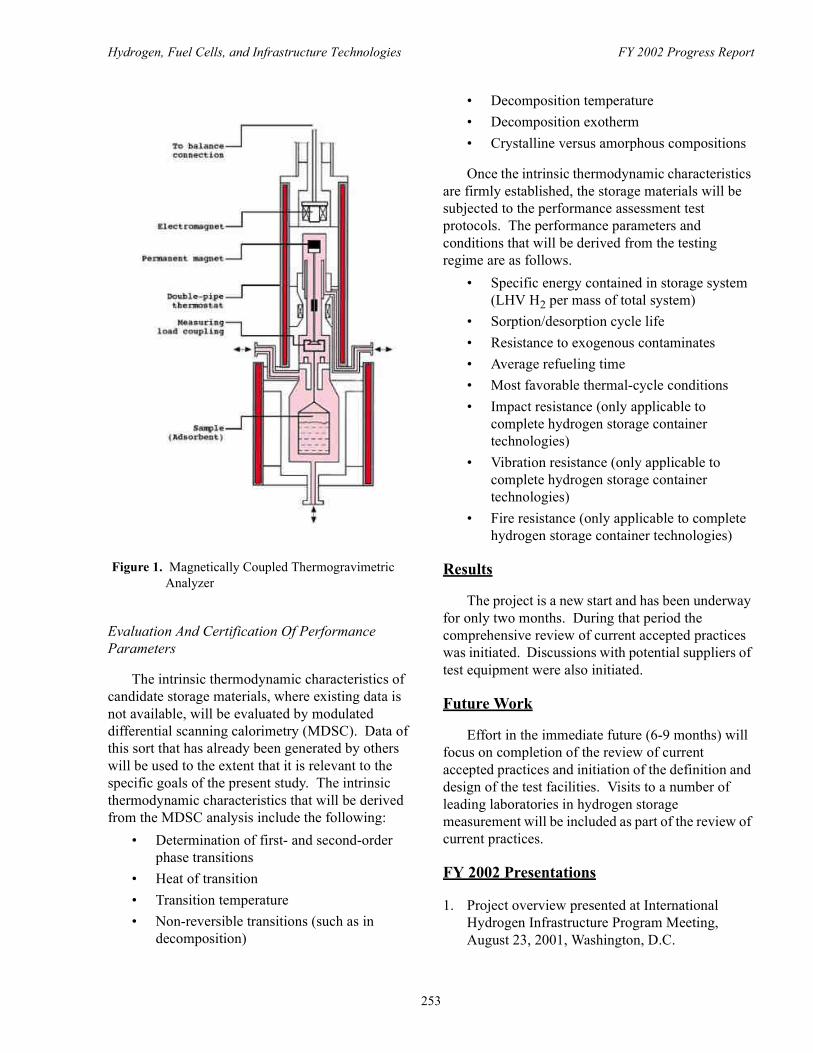
Hydrogen, Fuel Cells, and Infrastructure Technologies FY 2002 Progress Report
Evaluation And Certification Of Performance Parameters
The intrinsic thermodynamic characteristics of candidate storage materials, where existing data is not available, will be evaluated by modulated differential scanning calorimetry (MDSC). Data of this sort that has already been generated by others will be used to the extent that it is relevant to the specific goals of the present study. The intrinsic thermodynamic characteristics that will be derived from the MDSC analysis include the following:
• Determination of first- and second-order phase transitions
• Heat of transition• Transition temperature• Non-reversible transitions (such as in
decomposition)
• Decomposition temperature • Decomposition exotherm• Crystalline versus amorphous compositions
Once the intrinsic thermodynamic characteristics are firmly established, the storage materials will be subjected to the performance assessment test protocols. The performance parameters and conditions that will be derived from the testing regime are as follows.
• Specific energy contained in storage system (LHV H2 per mass of total system)
• Sorption/desorption cycle life• Resistance to exogenous contaminates• Average refueling time• Most favorable thermal-cycle conditions• Impact resistance (only applicable to
complete hydrogen storage container technologies)
• Vibration resistance (only applicable to complete hydrogen storage container technologies)
• Fire resistance (only applicable to complete hydrogen storage container technologies)
Results
The project is a new start and has been underway for only two months. During that period the comprehensive review of current accepted practices was initiated. Discussions with potential suppliers of test equipment were also initiated.
Future Work
Effort in the immediate future (6-9 months) will focus on completion of the review of current accepted practices and initiation of the definition and design of the test facilities. Visits to a number of leading laboratories in hydrogen storage measurement will be included as part of the review of current practices.
FY 2002 Presentations
1. Project overview presented at International Hydrogen Infrastructure Program Meeting, August 23, 2001, Washington, D.C.
Figure 1. Magnetically Coupled Thermogravimetric Analyzer
253

Hydrogen, Fuel Cells, and Infrastructure Technologies FY 2002 Progress Report
2. Project overview presented at DOE New Project Kick-Off Meeting, October 30, 2001, Washington, D.C.
3. Project overview presented at Hydrogen Program Annual Review, May 6-8, 2002, Golden, CO.
254

Hydrogen, Fuel Cells, and Infrastructure Technologies FY 2002 Progress Report
III.C.5 Hydrogen Fueled ICE Scooter with On-Board Metal Hydride Storage
Krishna Sapru (Primary Contact), S. Ramachandran, Z. Tan and P. SieversEnergy Conversion Devices, Inc.1621 Northwood Dr, Troy, MI 48084(248) 362-4780, fax: (248) 362-0012, e-mail: [email protected]
DOE Technology Development Manager: JoAnn Milliken(202) 586-2480, fax: (202) 586-9811, e-mail: [email protected]
Objectives• Convert a gasoline internal combustion engine (ICE) scooter into a commercially viable hydrogen
fueled scooter. • Design and fabricate a metal hydride storage system (MHSS) for on-board hydrogen storage.• Integrate the MHSS into the scooter for optimum utilization of the exhaust waste heat to release the
stored hydrogen.• Minimize backfiring and nitrogen oxide (NOx) emissions. Optimize power, range, and overall
efficiency/vehicle performance. • Develop preliminary business plan to involve scooter manufacturers, hydrogen producers and other
entities needed for commercialization.
Approach• Convert 80-250 cc four-stroke, gasoline-ICE scooters to operate on hydrogen, which involves making
changes to the fuel delivery and ignition systems.• Maximize engine power output with minimum emissions by optimizing suitable air/fuel ratio and
ignition timing.• Design improved metal hydride storage system and integrate into the exhaust system of the hydrogen-
ICE (H-ICE) scooter.• Perform chassis dynamometer tests under steady-state conditions, and road tests to evaluate fuel
consumption and drivability.• Install and operate an electrolyzer to deliver hydrogen as one means to charge the metal hydride
storage system on-board the scooter.• Perform a market study to determine the feasibility of introducing H-ICE scooters in developing
countries.
Accomplishments • Successfully converted and demonstrated a working hydrogen ICE Scooter.• Designed, fabricated, and integrated an air-cooled metal hydride storage system into the H-ICE
scooter.• Performed extensive dynamometer and road testing. • Acquired, installed and operated an electrolyzer which produces 10 normal cubic meters per hour
(approximately 1 kilogram per hour) hydrogen. Tested the purity, dryness, flow rate, and hydrogen delivery pressure, for compatibility with Energy Conversion Devices, Inc.’s (ECD’s) (Ovonic) metal hydrides.
255

Hydrogen, Fuel Cells, and Infrastructure Technologies FY 2002 Progress Report
• Completed an extensive market study, which indicates a very large market for H-ICE small vehicles in developing countries. Used India as a case study.
• Study performed to determine the availability and cost of hydrogen from various renewable sources.• Generated substantial awareness and interest in hydrogen for both transportation and distributed power
generation as a result of meetings and presentation in India to automotive manufacturers, hydrogen producers and several key government agencies.
Future Directions• Use knowledge/experience gained to improve overall H-ICE efficiency. This will be accomplished by
further research on the engine/vehicle performance (increase power, fuel economy and reduce NOx emissions).
• Identify optimal engine operational parameters such as air-flow, compression ratio, spark/fuel control, and valve timing, and develop an on-board fuel gauge.
• Incorporate improved metal hydride alloys and improve heat exchanger design along with additional engine work to increase the range from present 35 kilometers (km) to greater than150 km .
• Perform accelerated testing to check the compatibility between hydrogen and materials (i.e. corrosion and embrittlement) of various engine parts.
• Convert a liquid cooled 250 cc scooter to simulate the size of a 3-wheeler taxi in developing countries. Liquid heat exchange between engine coolant and metal hydride should provide better heat transfer.
• Leverage knowledge gained with hydrogen engine development for small vehicles (2 and 3 wheelers) and demonstrate H-ICE for distributed power generation.
• Explore federal/private partnerships for demonstrations and optimization.
Introduction
The global 2- and 3-wheeler fleet is in excess of 300 million units, most of them in highly polluted and rapidly developing nations such as China and India. While the Organization for Economic Cooperation and Development (OECD) countries are currently the largest contributors to greenhouse gas emissions, the Asia and Pacific regions are expected to replace OECD countries as the largest source of greenhouse gas emissions worldwide by about 2015. Development of small vehicles and power generation devices to run on hydrogen would result in dramatic improvement in air quality, in addition to economic and energy security benefits for all.
Developing clean hydrogen combustion technologies will not defer, but speed up a global transition to fuel cell technologies by promoting early hydrogen infrastructure development. Fuel cell power will be more energy efficient in the long run, but it is at least 15-20 years away from commercialization, especially in the industrialized nation where the per capita energy demand and
performance expectations are very high. ICE manufacturing and maintenance capabilities are already established and only minimal re-tooling is needed. In addition to hydrogen conversion technologies, widespread availability of cost effective hydrogen fuel is required. A study was undertaken to compare the cost and availability of hydrogen from renewable sources in India. This study showed three possible sources:
• Use of low cost electricity from the bagasse co-generation in sugar mills to produce hydrogen via electrolysis of water
• Hydrogen by-product from the chlorine-caustic industry
• Direct gasification of biomass to hydrogen
Metal hydrides that reversibly store and deliver hydrogen at low temperatures and pressures offer a compact and safe means to carry hydrogen on-board small vehicles. Storage of hydrogen as a solid offers superior safety and volumetric advantages versus gaseous or liquid storage. In addition, large-scale metal hydride production facilities are already in
256

Hydrogen, Fuel Cells, and Infrastructure Technologies FY 2002 Progress Report
place (due to commercialization of the nickel/metal hydride battery technology), and this investment can be leveraged to produce alloys for hydrogen storage.
Approach
Our approach is to work with small ICE vehicles with engines in the 80-250 cc range, since this covers the broadest segment of the market. Vehicle conversion involves making changes to the fuel delivery and ignition systems.�We will work on the vehicle to obtain maximum engine power with minimum emissions by determining suitable air/fuel ratio and ignition timing over the operating range of the engine.
In addition to vehicle optimization, we will use higher capacity metal hydride alloys developed at ECD, coupled with improved heat exchangers. This improved metal hydride storage system will be integrated into the vehicle for optimum utilization of waste heat. Detailed performance characteristics under different sets of driving conditions will determine areas of further improvement if necessary.
Results
We successfully converted an 80 cc gasoline ICE scooter to run on hydrogen fuel (Figures 1 and 2). This scooter was demonstrated at the U.S. DOE Annual review meeting in Denver, Colorado in May, 2002, and also at the World Hydrogen Energy Conference in Montreal in June, 2002. The conversion was achieved by making changes to the fuel delivery system and the ignition system. The scooter uses a fuel injector controlled by an engine control unit. The carburetor was removed and a throttle body was designed to replace the carburetor.
A driving test was done on a warm day in Michigan when the temperature was 92o F, the barometric pressure 30 inches of mercury and humidity range of 46-55%. The on-board metal hydride storage system was charged with 140 grams of hydrogen and a range of 35 kilometers was obtained, with an approximate fuel consumption of 3.8 grams of H2 per kilometer. The average speed during this test run was 32 km/hour and the top speed was 40 km/hour.
The metal hydride used in the 80 cc scooter had 1.5 weight % reversible hydrogen-storage capacity. Within the geometrical constraints, using the same alloy, up to 240 grams of hydrogen can be carried on-board resulting in a range increase from the present 35 km to 60 km. Additionally, we recently developed new alloys having reversible hydrogen-storage capacities of 2.6 weight % (Figure 3). Using these
Figure 1. 80 cc, Four-Stroke, Single Cylinder Scooter Converted to Run on Hydrogen
Figure 2. ECD's Proprietary Metal Hydride Storage System On-Board, Under the Seat
257

Hydrogen, Fuel Cells, and Infrastructure Technologies FY 2002 Progress Report
new alloys along with planned improvements in engine/vehicle performance will allow us to increase the vehicle range to 150 km. A 50 km to100 km vehicle range could be commercially acceptable in many developing countries, where the average daily driving range is less than 20 km, and gasoline prices are between U.S. $4 to $5 per gallon. These are also regions where air quality is among the worst in the world.
Distributed Power Generation for Portable and Stationary Use
It is estimated that 40% of the world’s population is without electric power. These non-electrified regions of the world are potential markets for distributed small-scale (0.5-3 kilowatt) power systems. Also, because of severe power shortages and frequent outages in regions that do have electricity, there is a need to replace highly polluting diesel engines, gasoline and kerosene generators currently being used extensively; thus, the demand for hydrogen for power generation can be enormous. Figure 4 shows ECD’s laboratory prototype of a H-ICE generator.
Conclusion
With support from the U.S. DOE hydrogen program, ECD has demonstrated the viability of H-ICE scooters with metal hydride for on-board hydrogen storage. Hydrogen fueled small ICE vehicles and distributed power generation devices
can improve global air quality and reduce our dependence on fossil fuels. These products can be commercialized in a relatively short time frame (3-5 years) and pave the way to a hydrogen economy. However, additional research and demonstration projects are needed. Research should focus on improving fuel economy, reducing nitrogen oxides, improving power and vehicle range, materials compatibility and reducing overall cost.
Presentations
1. K. Sapru, S. Ramachandran, Z. Tan, 12th Annual US National Hydrogen Association, March 6-8, 2001, meeting in Washington, DC.
2. K. Sapru, S. Ramachandran, Z. Tan “Hydrogen- The New Oil- for Sustainable Transportation & Distributed Power Generation”, invited talk at “International Symposium & Exposition on Alternative Energy Vehicles”, Indian Institute of Technology, November 23-25, 2001, Kanpur, India.
3. K. Sapru, “Hydrogen –The New Oil. Near Term Business Opportunities for Hydrogen in Developing Countries”, The 2002 Hydrogen Investment Forum, April 3-4, 2002, Washington, DC,
4. K. Sapru, Hydrogen – “The New Oil”, Hydrogen for Transportation and Distributed Power for
Figure 3. Hydrogen Desorption Kinetics of Proprietary Ovonic Hydrogen Storage Alloys at 100oC FY 2002
Figure 4. Laboratory Model of Ovonic Hydrogen ICE Generator Powered by Metal Hydride Storage Providing 3 hours of Back-Up Power at 2 kilo watts electrical
258

Hydrogen, Fuel Cells, and Infrastructure Technologies FY 2002 Progress Report
India, invited talk presented at the Science & Technology India Conference, April 10-12, 2002, New Delhi, India.
5. Z. Tan and K. Sapru, “Calcium Lithium Based Hydrogen Storage Materials”, Canadian Hydrogen Storage Workshop sponsored by Canadian NRC, February, 2002, Ottawa, Canada.
6. K. Sapru, First Indo-US Fuel Cell Meeting, June 2-4, 2002, Washington, DC.
Patent Applications
During 2001-2002, the following patent applications have been filed:
1. S. Ramachandran, P. Sievers, K. Sapru and Z. Tan, A Hydrogen Powered Scooter, US patent pending.
2. Z. Tan and K. Sapru, High Capacity Calcium Lithium Based Hydrogen Storage Material and Method of Making the Same, US patent pending.
3. K. Sapru, Z. Tan, M. Bazzi, and S. Ramachandran, High Capacity Transition Metal Ti-V-Cr-Mn based Hydrogen Storage Materials, US patent pending.
259
Hydrogen, Fuel Cells, and Infrastructure Technologies FY 2002 Progress Report
III.C.6 Hydride Development For Hydrogen Storage
Karl Gross (Primary Contact), E. Majzoub, G.J. Thomas, G. Sandrock Sandia National LaboratoriesP.O. Box 969Livermore, CA 94551(925) 294-4639, fax: (925) 294-3410, e-mail: [email protected]
DOE Technology Development Manager: JoAnn Milliken(202) 586-2480, fax: (202) 586-9811, e-mail: [email protected]
Objectives • Develop new complex hydride materials with 6 weight percent system hydrogen capacity.• Improve the kinetics of absorption and desorption and thermodynamic plateau pressures of Ti-doped
sodium alanate metal hydrides.• Improve processing and doping techniques of Ti-doped sodium alanate which will lower cost.
Approach• Developing new complex hydrides to achieve higher capacities.• Innovate methods to synthesize the complex hydrides and improve the doping process to improve both
rates and capacity. Test different Ti-halide catalyst-precursor materials and other Ti-containing alloys and hydrides to determine the efficacy of Ti-doping with other starting materials.
• Characterize the material properties of each new generation of complex hydrides to aid in further improvements. Compare different material responses using kinetics experiments coupled with analytic techniques such as X-ray, electron spin resonance (ESR), nuclear magnetic resonance (NMR), Auger spectroscopy, etc.
• Determine the hydriding mechanisms through experimental analysis and modeling. Using Sievert’s apparatus, measure rates of absorption and desorption of hydrogen from Ti-doped sodium alanate. Determine Arrhenius behavior and find activation energies and rate constants. Compare these results with mechanistic studies including neutron diffraction and ab initio calculations (electronic structure calculations.
• Evaluate the behavior of the materials on an engineering scale to ensure that they are on track for eventual commercialization.
Accomplishments • Improved reversible capacities with the use of direct material synthesis and lower weight titanium (Ti)-
halides such as titanium dichloride (TiCl2) as catalyst precursors now give 4.3 weight % hydrogen (H2).
• Discovery that Ti-halides with Ti valency of 2+, 3+, and 4+ work as catalysts in the sodium alanate system.
• Simplification of processing procedure for manufacture of Ti-doped sodium alanate from raw materials of Na, Al, and Ti-halide, resulting in a patent application.
Future Directions • Find new complex metal hydrides and catalysts using procedures and techniques developed during the
sodium alanate investigations.
260

Hydrogen, Fuel Cells, and Infrastructure Technologies FY 2002 Progress Report
• Determine the mechanism of action of the Ti in the material for the enhanced kinetics.• Find new methods to introduce Ti into sodium alanate that may be more beneficial and economical
than Ti-halide introduction.
Introduction
Ti-doped alanates offer an entirely new prospect for lightweight hydrogen storage. These materials have nearly ideal equilibrium thermodynamics, good packing densities, moderate volume expansion and useful sintering properties. However, there is much room for improving both absorption and desorption kinetics, and the less-than-theoretical reversible capacities. Our work has focused on finding solutions to these problems to achieve the performance requirements needed to supply onboard hydrogen for PEM fuel cell powered vehicles.
Approach
Dehydriding and hydriding rates and capacities were obtained volumetrically using a Sieverts’ apparatus and a cylindrical 316L stainless steel reactor (1.3 centemeter [cm] outer diameter by 0.12 cm wall thickness and length of 12 cm) containing about 1.5 gram of catalyzed samples. A thermocouple well in the center of the vessel allows for accurate temperature measurements during cycling. Absorption pressure changes were quantified with a calibrated 200 atmosphere absolute (atma) pressure transducer and desorption pressures with a 1000 Torr (1.3 atma) Baratron® capacitance manometer. Data were recorded via computer, and measurements lasted from minutes to several days, depending on the Ti-doping level, test pressure, and temperature conditions.
During absorption, the applied H2 pressure was generally in the 80-90 atm range, well above the 30-40 atma plateau pressure for sodium tetrahydroaluminate (NaAlH4) at 125°C. For the desorption experiments, the back-pressure during NaAlH4 decomposition was kept below 1 atma and during trisodium hexahydroaluminate (Na3AlH6) decomposition below 0.25 atma, well below the Na3AlH6 plateau pressure of about 2 atma. Hydrogen capacity data are presented in Figure 1 as weight % with respect to the total sample weight, including the catalyst.
Isothermal arrhenius analysis were performed as follows. Measurements were started after several hydriding/dehydriding cycles with samples in the fully hydrided condition and cooled to room temperature. The pressure rise from desorption into a known volume at a given temperature was measured; and the temperature was then increased. Desorption rates were determined at each temperature from the slope of the essentially linear increase in pressure with time. This procedure was continued up to 150°C. The sample was held at this temperature until the NaAlH4 decomposition step was finished. The rate data are presented as moles of desorbed hydrogen per mole active sodium per hour as shown in Figure 2.
Results
To improve capacity we have investigated the use of Ti-halides other than TiCl3 to catalyze hydrogen absorption and desorption in NaAlH4. Titanium triflouride (TiF3) and TiCl2 appear to work equally as well as TiCl3 and reduce the overall capacity loss due to the formation of sodium chloride (NaCl) or sodium flouride (NaF).
Two new generations of materials have been developed. These are Generation III and Generation IV Ti-doped sodium alanates that are synthesized
Figure 1. Reversible Hydrogen Capacity as a Function of TiCl3 Content
261

Hydrogen, Fuel Cells, and Infrastructure Technologies FY 2002 Progress Report
directly from sodium hydride (NaH), Al, Ti-dopant and Na-metal, Al, Ti-dopant, respectively. These materials have demonstrated better kinetics than materials produced using earlier methods. In addition, the direct synthesis is performed without the use of solvents.
The result is a hydrogen storage material that is less-expensive to produce and delivers hydrogen free of hydrocarbon impurities.
Conclusions
We developed a synthesis route to produce Na3AlH6 and NaAlH4 directly from Na and Al metals (patent application submitted).
We discovered that it is the titanium that contributes to the enhanced kinetics; the Ti-halide precursor gives the same results independent of the halide that is used. For that reason, the use of Ti-fluorides or lower Cl content chlorides will provide an incremental improvement in the reversible weight capacity.
A preliminary investigation shows that the direct synthesized alanates undergo an activation consisting of 2-3 cycles. Following this, it appears that the capacity and rates are quite stable after many cycles.
Aluminum is consumed in forming the alanates. It was found that it doesn’t matter where the aluminum comes from (i.e. sorption materials or container vessel walls). However, the use of alanates that are not aluminum deficient did not appear to degrade the strength of aluminum-based alloys when tested under long-term cycling conditions.
In summary, these results demonstrate that solid progress is being made on the development of alanates for mobile hydrogen storage applications.
References
1. Bogdanovic, B. and Schwickardi, M. 1997. “Ti-doped alkali metal aluminum hydrides as potential novel reversible hydrogen storage materials”, J. Alloys and Compounds, 253:1.
2. Bogdanovic, B., Brand, R.A., Marjanovic, A., Schwikardi, M., and Tölle, J. 2000. “Metal-doped sodium aluminum hydrides as potential new hydrogen storage materials”, J. Alloys and Compounds, 302:36.
3. Bogdanovic, B., Schwickardi M. 2001. “Ti-doped NaAlH4 as a hydrogen-storage material – preparation by Ti-catalyzed hydrogenation of aluminum powder in conjunction with sodium hydride”, Applied Physics A, 72 (#2):221.
FY 2002 Publications/Presentations
1. Gross, K. J., Thomas, G. J. and Jensen, C. M., “Catalyzed Alanates for Hydrogen Storage”, Journal of Alloys and Compounds, review article, 330-332 (2002) 683.
2. Gross, K. J., Sandrock, G., and Thomas, G. J., “Dynamic In Situ X-ray Diffraction of Catalyzed Alanates”, Journal of Alloys and Compounds, 330-332 (2002) 691.
3. Gross, K. J., Majzoub, E.H., Thomas, G. J., and Sandrock, G. 2002 " Hydride Development for Hydrogen Storage”, Proceedings of the 2002 U.S. DOE Hydrogen Program Review NREL/CP-610-32405.
4. Majzoub, E.H., Somerday, B.P., Goods, S.H., and Gross, K.J. 2002. “Interaction between Sodium
Figure 2. Arrhenius Plot of the Hydrogen Desorption Rates vs. 1/T for the Decomposition of NaAlH4
262

Hydrogen, Fuel Cells, and Infrastructure Technologies FY 2002 Progress Report
Aluminum Hydride and Candidate Containment Materials”, Proceedings of the Conference on Hydrogen Effects on Material Behavior, Jackson Hole Wyoming, N. Moody editor.
5. G. Sandrock, K. J. Gross, and G. J. Thomas, “Effect of Ti-Catalyst Content on the Reversible Hydrogen Storage Properties of the Sodium Alanates”, Journal of Alloys and Compounds, 339 (2002) 299-308.
6. G. J. Thomas, G. Sandrock, N. Yang, and K. J. Gross, ‘Microstructural Characterization of Catalyzed NaAlH4’, Journal of Alloys and Compounds, 330-332 (2002) 702.
7. G. Sandrock, K. J. Gross, G. J. Thomas, C. M. Jensen, D. Meeker, and S. Takara, “Engineering Considerations in the Use of Catalyzed Sodium Alanates for Hydrogen Storage”, Journal of Alloys and Compounds, 330-332 (2002) 696.
8. Gross, K. J., Majzoub, E.H., “New Reversible Complex Hydrides for Practical Hydrogen Storage”, presentation World Hydrogen Energy Conference, Montreal, Canada, June 9th-13th, 2002.
9. Gross, K. J., Majzoub, E.H., and Sandrock, G. “Complex Hydrides for Light-Weight Hydrogen Storage”, presentation TMS Annual Meeting, Seattle WA, February 20, 2002.
Special Recognitions & Awards/Patents Issued
1. DOE OPT Young Investigator Award – K. J. Gross.
2. Patent application. “Direct synthesis of lightweight catalyzed hydride for hydrogen storage.” May 3, 2001.
263

Hydrogen, Fuel Cells, and Infrastructure Technologies FY 2002 Progress Report
264