section c2: outfall construction and design
TRANSCRIPT
Tramore Sewerage Scheme WWDL Application _______________________________________________________________________________________________________
_____________________________________________________________________ MCW0498 69 Rev. A01
SECTION C2: OUTFALL CONSTRUCTION AND DESIGN Table of Attachments
Item Title Map/Photo No. 1 Stormwater Overflow Manholes Drg. No. 3 2 Plan and Longitudinal Section of Sea Outfall from
Tramore WWTP Drg. No. 4
3 Details of Diffuser at Primary Discharge Point and Outfall Manhole ‘OF 6’
Drg. No. 5
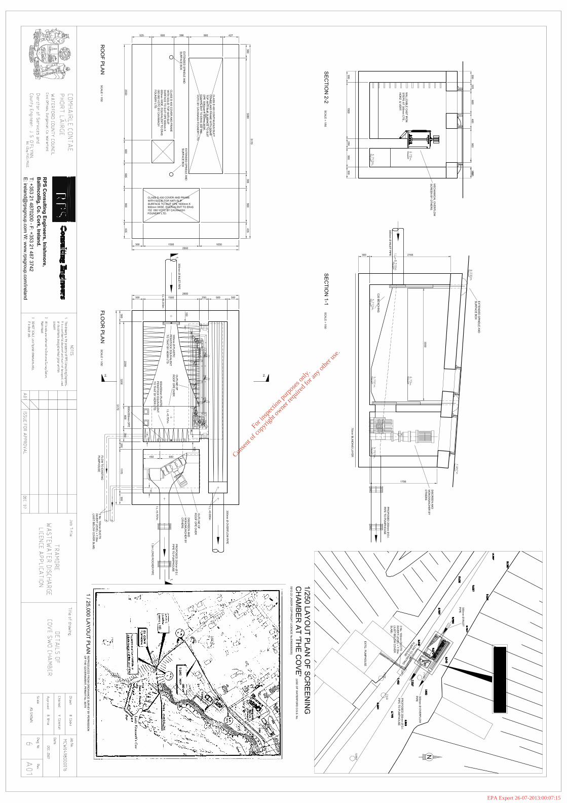
4 Details of Cove SWO Chamber Drg. No. 6 The primary discharge point from Tramore Wastewater Treatment Plant was constructed in 2005 in accordance with Drg. Nos. 4 and 5 of this attachment. SW1: Primary Discharge Point The final effluent from the Treatment Plant is discharged to an 800 mm PE100 SDR 17.6 polyethylene pipe, which outfalls to Tramore Bay at the location shown on Drawing No. 4 of this attachment. (Also refer to the drawings and photographs in Attachment No. B3). A multi-port diffuser has been constructed at the discharge point in accordance with Drg. No. 5 of this attachment. The invert level at the point of discharge is -16.17 mOD (Malin Head). Type of Discharge
800 mm diameter outfall pipe from Waste Water Treatment Works, with multi-port diffuser at discharge point (SW1)
Grid ref (6E, 6N)
259370E, 98984N (SW1)
For
insp
ectio
n pur
pose
s only
.
Conse
nt of
copy
right
owne
r req
uired
for a
ny ot
her u
se.
EPA Export 26-07-2013:00:07:15

Tramore Sewerage Scheme WWDL Application _______________________________________________________________________________________________________
_____________________________________________________________________ MCW0498 70 Rev. A01
The construction of the following overflows pre-dates the Urban Wastewater Treatment Directives, therefore the design of the chambers is not based on the following:
• dilution rates or capacity in relation to dry weather flow or • a specified number of overflow events per year
The National Urban Waste Water Study, Volume 2, Part C states that Irish national regulations dictate that both spill frequency and volume are restricted as regards the protection of bathing waters whilst screening to prevent the escape of visible debris also requires consideration. In recent years, 6 mm fine screens have been fitted to the existing chambers. These mechanically raked screens contain solids in the SWO chambers during period of overflow. SW2: Secondary Discharge Point There is an emergency overflow from the Promenade Pumphouse, which comes into operation when pump failure occurs and flow backs up in the system. The overflow chamber is located at Mh. 50, which is located upstream of the pumphouse. Overflow from this chamber is spilled to Mh. 60 in a 525 mm diameter overflow pipe. From Mh. 60 the flow is discharged to the beach via a 300 mm pipe running southwards from Mh. 60. Refer to the drawings and photographs in Attachment No. B4. Details of the overflow chamber, Mh. 50, are shown on Drg. No. 3 of this attachment. The invert level of the overflow pipe at the chamber is 0.83 mOD (Malin Head). (Also refer to the drawings and photographs in Attachment No. B4). Type of Discharge
Overflow Weir in Mh. 50 (SWO1) Overflow discharged to beach via 300 mm diameter overflow pipe (SW2)
Grid ref (6E, 6N)
258990E, 101148N (SWO1) 258996E, 101067N (SW2)
SW3: Stormwater Overflow from Mh. 80 Mh. 80 is a stormwater overflow chamber situated towards the eastern end of the Promenade near the Lifeguard Station. Spill from this chamber is subjected to fine screening before being discharged to the 28 meters of 300 mm diameter overflow, which exits through the Promenade wall onto the beach. Details of the overflow chamber, Mh. 80, are shown on Drg. No. 3 of this attachment. The invert level at the point of discharge is 2.18 mOD (Malin Head). (Also refer to the drawings and photographs in Attachment No. B5). Type of Discharge
Overflow Weir in Mh. 80 (SWO2) 300 mm diameter combined sewer overflow pipe (SW3)
Grid ref (6E, 6N)
258786E, 101130N (SWO2) 258772E, 101107N (SW3)
For
insp
ectio
n pur
pose
s only
.
Conse
nt of
copy
right
owne
r req
uired
for a
ny ot
her u
se.
EPA Export 26-07-2013:00:07:15

Tramore Sewerage Scheme WWDL Application _______________________________________________________________________________________________________
_____________________________________________________________________ MCW0498 71 Rev. A01
SW4: Stormwater Overflow from Mh. 47 Mh. 47 is the largest of the Tramore SWOs in terms of spill volumes recorded. It is located on the Strand Road opposite the Arcade Amusement Centre. There is a 600mm overflow pipe from Mh. 47. This is 162 m in length with 2 no. manholes (45 and 46), and discharges to the beach through the Promenade wall adjacent to the slip at the end of Strand Street through a short length (14 m) of masonry culvert. Details of the overflow chamber, Mh. 47, are shown on Drg. No. 4 of this attachment. The invert level at the point of discharge is 3.76 mOD (Malin Head). (Also refer to the drawings and photographs in Attachment No. B5). Type of Discharge
Overflow Weir in Mh. 47 (SWO3) Masonry culvert to beach outfall (SW4)
Grid ref (6E, 6N)
258330E, 101244N (SWO3) 258220E, 101099N (SW4)
SW4: Stormwater Overflow from Mh. 14 There is an SWO chamber, Mh. 14, located on Strand Street at the side of O’Shea’s Hotel. There is a 600 mm overflow pipe from the chamber which discharges to Manhole 45 on the overflow from the Arcade SWO (Manhole 47), 14 m upstream of where the masonry culvert discharges to the beach through the Promenade wall. (Refer to the drawings and photographs in Attachment No. B5). Details of the overflow chamber, Mh. 14, are shown on Drg. No. 4 of this attachment. The invert level at the point of discharge is 3.76 mOD (Malin Head). (Also refer to the drawings and photographs in Attachment No. B5). Type of Discharge
Overflow Weir in Mh. 14 (SWO4) Masonry culvert to beach outfall (SW4)
Grid ref (6E, 6N)
258211E, 101139N (SWO4) 258220E, 101099N (SW4)
SW5: Stormwater Overflow from Cove SWO Cove SWO chamber is located on The Cove, situated to the south west of Tramore Strand. It is immediately upstream on the adjacent Cove Pumping Station. Wastewater from this pumping station is pumped to Doneraile Walk, from where it gravitates to the Promenade Pumphouse. Overflow from Cove SWO occurs when the storage at the pumping station is insufficient and flow backs up to the SWO. A 300 mm diameter overflow from the SWO chamber carries the spill to a 450 mm diameter pipe which discharges to the sea on the eastern side of the harbour. Details of Cove SWO chamber are shown on Drg. No. 6 of this attachment. The invert level at the point of discharge is 4.47 mOD (Malin Head). (Also refer to the drawings and photographs in Attachment No. B5). Type of Discharge
Overflow Weir at The Cove SWO Chamber (SWO5) 450 mm diameter combined sewer overflow pipe to beach outfall (SW5)
Grid ref (6E, 6N)
257560E, 100497N (SWO5) 257625E, 100507N (SW5)
For
insp
ectio
n pur
pose
s only
.
Conse
nt of
copy
right
owne
r req
uired
for a
ny ot
her u
se.
EPA Export 26-07-2013:00:07:15

For
insp
ectio
n pur
pose
s only
.
Conse
nt of
copy
right
owne
r req
uired
for a
ny ot
her u
se.
EPA Export 26-07-2013:00:07:15

For
insp
ectio
n pur
pose
s only
.
Conse
nt of
copy
right
owne
r req
uired
for a
ny ot
her u
se.
EPA Export 26-07-2013:00:07:15

For
insp
ectio
n pur
pose
s only
.
Conse
nt of
copy
right
owne
r req
uired
for a
ny ot
her u
se.
EPA Export 26-07-2013:00:07:15
For
insp
ectio
n pur
pose
s only
.
Conse
nt of
copy
right
owne
r req
uired
for a
ny ot
her u
se.
EPA Export 26-07-2013:00:07:15