section 6 water supply -...
TRANSCRIPT
Section 6:
Water Supply
Tauranga City Council
Code of Practice for Development Tauranga City Council SECTION SIX WATER
Print Date May 2007- VERSION ONE TCC Ref: 790836
2
Contents 6.A Overview 6.A.1 Scope 6.A.2 Standards and Water Supply Bylaw 6.A.3 Levels of Service 6.A.4 Contributions 6.B Design of Watermains 6.B.1 Design 6.B.2 Domestic Supply 6.B.3 Commercial and Industrial Supply 6.B.4 Fire Fighting Supply 6.B.5 Working Pressures 6.C Pipe Selection
6.C.1 Sizing of Mains 6.C.2 Pipe Class 6.C.3 Pipe Sizing 6.C.4 Pumped Water Reticulation Systems 6.C.5 Accepted Pipe Materials
6.D Layout of Reticulation Systems General Position of Reticulation Systems 6.D.1 Reticulation Layout 6.D.2 Mains Layout 6.D.3 Pipe Depths 6.D.4 Trench Widths 6.D.5 Alignment Tolerances 6.D.6 Mains Intersections 6.D.7 Close Proximity Rules 6.D.8 Watermains in Easements 6.D.9 Shared Trenching 6.D.10 Saline and Contaminated Areas 6.D.11 Trenchless Techniques 6.E System Restraints General Requirement 6.E.1 Thrust Blocks 6.E.2 Anchor Blocks 6.E.3 Restrained Joint Watermains 6.E.4 Bulkheads 6.F Ridermains 6.G Valves General 6.G.1 Valve Types 6.G.2 Gate Valves 6.G.3 Butterfly Valves 6.G.4 Valves for Principal Mains 6.G.5 Location Marking of Valves 6.G.6 Valve Spacing Criteria 6.G.7 Valve Boxes 6.G.8 Branch Mains 6.G.9 Pressure Zone Dividing Valves 6.G.10 Secure Service Connections
Code of Practice for Development Tauranga City Council SECTION SIX WATER
Print Date May 2007- VERSION ONE TCC Ref: 790836
3
6.G.11 Pressure Reducing Valves 6.G.12 Air Valves 6.G.13 Scour Valves and Pump-out Branches 6.H Hydrants 6.H.1 General 6.H.2 Hydrants (for fire fighting purposes) – Location and Spacing Requirements 6.H.3 Hydrant Installation 6.H.4 Hydrants (for operational purposes) – Location and Spacing Requirements 6.H.5 Hydrant Boxes 6.I Property Service Connections 6.I.1 Size 6.I.2 Point of Supply (POS) to Consumer 6.I.3 Diameter and Pipe Materials 6.I.4 Tapping Bands 6.I.5 Connections 6.I.6 Service Connections 6.I.7 Metered Connection Location 6.I.8 Backflow Protection 6.J Termination Points 6.J.1 Mains Termination – Water Quality 6.J.2 Mains Termination - Future Development 6.K Bends and Tees 6.L Construction of Pipelines 6.L.1 Excavation 6.L.2 Bedding 6.L.3 Carriageway Trench Re-instatement 6.L.4 Berms 6.L.5 Tracer Wire 6.M Reservoir and Pumping Stations 6.N Water Quality 6.N.1 Materials 6.N.2 Prevention of Back Siphonage 6.N.3 Water Age 6.O System Test Pressure 6.P System Disinfection 6.Q Connection of New Mains to Existing Mains 6.Q.1 Temporary Access to Mains Water 6.Q.2 Connection of new mains to existing networks 6.R Approved Contractors
Code of Practice for Development Tauranga City Council SECTION SIX WATER
Print Date May 2007- VERSION ONE TCC Ref: 790836
4
PART 6: WATER SUPPLY 6.A.1 Scope
This section of the Code is applicable for servicing new green-field developments, re-development areas, and commercial and industrial developments. It covers the design of both the localised reticulation system and the larger distribution network. For pipe systems greater than DN 375 specific consultation is Council is required.
6.A.2 Standards and Supply Bylaw a) Council is empowered by the Local Government Act 2002, the Health Act 1956, and the Rating Powers Act 1988 to make bylaws to:
• Protect public health and the security of the public water supply;
• Detail the responsibilities of both Council and consumers with respect to the public water supply;
• Detail different types of water supply; • Detail mechanisms for the recovery of costs of
water supply; • Prevent the wastage of water; • Provide a mechanism for demand management; • Detail breaches and offences and provide a disputes
procedure. This bylaw is based on NZS 9201:1994 Chapter 7, Water Supply and amended where appropriate to reflect local requirements.
This bylaw should be read in conjunction with this Code.
A copy of this bylaw may be viewed at the Council offices or online at [email protected]
b) In conjunction with the above bylaw the design, construction and testing of water reticulation systems to be vested in Council or for Council shall utilise Part 6 of NZS 4404 Land Development and Subdivision Engineering. This standard provides the guidelines and standards required to be adhered to by the designer, supervisor and constructor when designing, constructing and testing water systems for Council.
Code of Practice for Development Tauranga City Council SECTION SIX WATER
Print Date May 2007- VERSION ONE TCC Ref: 790836
5
6.A.3 Level of Service
The water supply reticulation system shall be designed and constructed to comply with SNZ PAS 4509 and shall ensure that a water supply connection is available to each allotment in accordance with the District Plan requirements. The minimum firefighting residual running water pressure shall be 100 kPa (10m head of water) at all hydrants. The minimum working residual water pressure, other than in firefighting conditions, shall be 300 kPa (30m head of water) at the ground level of each building platform for each allotment.
6.A.4 Contributions Where water mains have been or are to be installed by Council, contributions on an area basis shall be made in terms of the development impact fees or other agreed cost sharing arrangement
Code of Practice for Development Tauranga City Council SECTION SIX WATER
Print Date May 2007- VERSION ONE TCC Ref: 790836
6
6.B Design of Watermain Systems 6.B.1 Design
All reticulations systems shall be designed in accordance with NZS 4404 and the following criteria. For the purposes of this Code design incorporates supply, peak flows, hydraulic design, minimum and maximum working pressures, network analysis, head loss, pipe construction, testing of proposed systems, pressures and the like. NZS 4404 provides the design basis on which Council requires design to be undertaken. Council reserves the right to specify the size of the principal and rider watermains within the development where it deems amendment from any standard is required.
6.B.2 Domestic Supply
In developments of an average size, the domestic demand is not critical and the supply of water for firefighting purposes will generally determine the pipe sizes required. For more extensive areas however the pipe network shall be designed to provide for annual, seasonal and peak demand utilising the available pressures in the existing mains. The design shall provide for an average domestic demand of 430 litre/head/day with a peak flow of 4.3 times this amount.
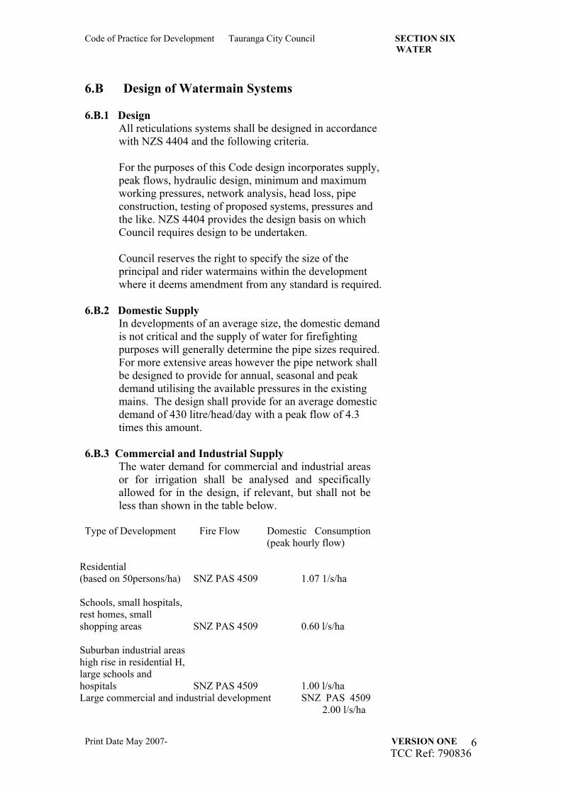
6.B.3 Commercial and Industrial Supply The water demand for commercial and industrial areas or for irrigation shall be analysed and specifically allowed for in the design, if relevant, but shall not be less than shown in the table below.
Type of Development Fire Flow Domestic Consumption
(peak hourly flow)
Residential (based on 50persons/ha) SNZ PAS 4509 1.07 1/s/ha
Schools, small hospitals, rest homes, small shopping areas SNZ PAS 4509 0.60 l/s/ha
Suburban industrial areas high rise in residential H, large schools and hospitals SNZ PAS 4509 1.00 l/s/ha Large commercial and industrial development SNZ PAS 4509
2.00 l/s/ha
Code of Practice for Development Tauranga City Council SECTION SIX WATER
Print Date May 2007- VERSION ONE TCC Ref: 790836
7
6.B.4 Fire Fighting Supply
The water reticulation shall be designed to comply with s6.A.2 (SNZ PAS 4509) above with regard to firefighting flows, running pressure and the spacing of hydrants, together with any additional requirements set out herein, including storage where applicable. Unless stated otherwise in the Council’s standard requirements, the fire risk classification shall be as shown in the standards above.
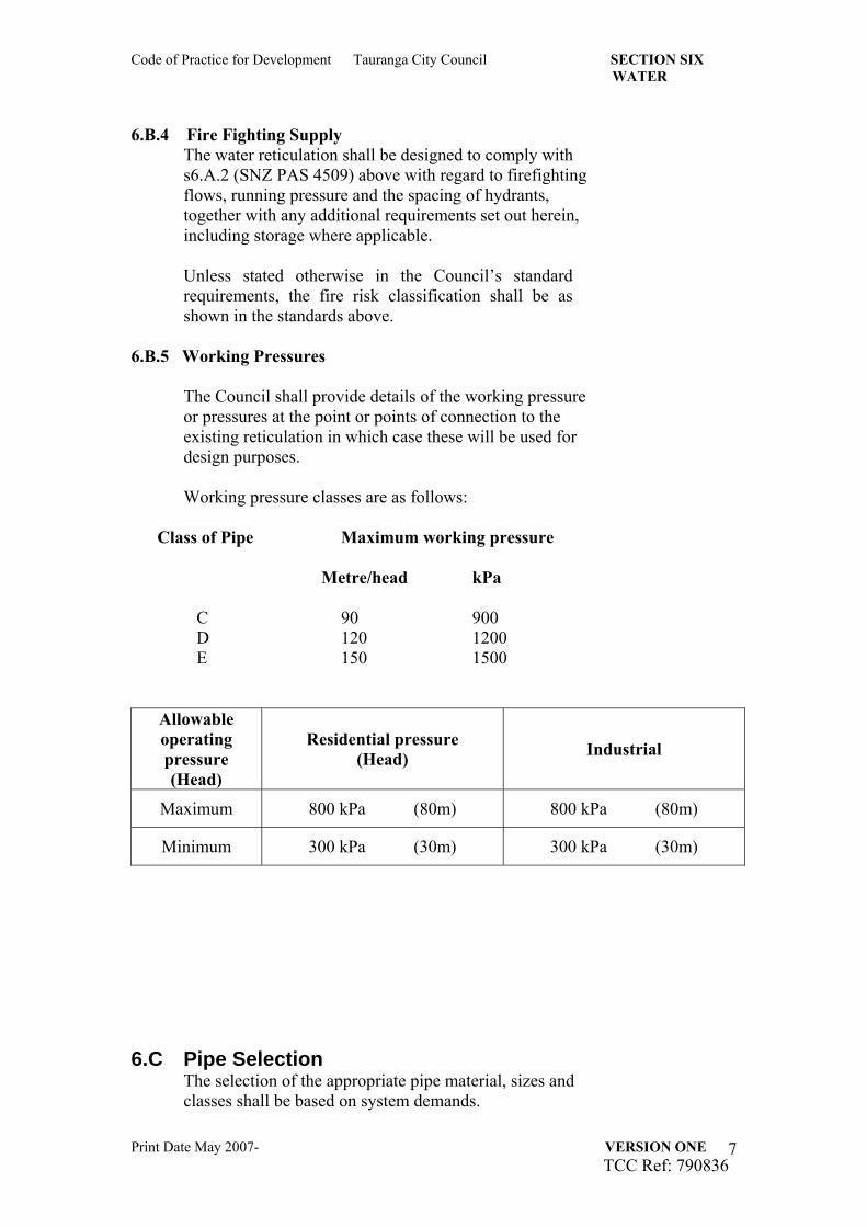
6.B.5 Working Pressures
The Council shall provide details of the working pressure or pressures at the point or points of connection to the existing reticulation in which case these will be used for design purposes. Working pressure classes are as follows:
Class of Pipe Maximum working pressure Metre/head kPa C 90 900 D 120 1200 E 150 1500
Allowable operating pressure (Head)
Residential pressure (Head) Industrial
Maximum 800 kPa (80m) 800 kPa (80m)
Minimum 300 kPa (30m) 300 kPa (30m)
6.C Pipe Selection
The selection of the appropriate pipe material, sizes and classes shall be based on system demands.
Code of Practice for Development Tauranga City Council SECTION SIX WATER
Print Date May 2007- VERSION ONE TCC Ref: 790836
8
6.C.1 Sizing of mains
Water mains shall be sized to ensure that residual pressures due to peak demands are not less than the minimum standards required by this Code.
6.C.2 Pipe class
Pipes for water mains shall be a minimum of PN9 or equivalent although a higher class shall be used if necessary to provide for the maximum working pressure in the area in which they are laid or to allow for future development in the area. This may be varied by specific operational requirements specified by Council.
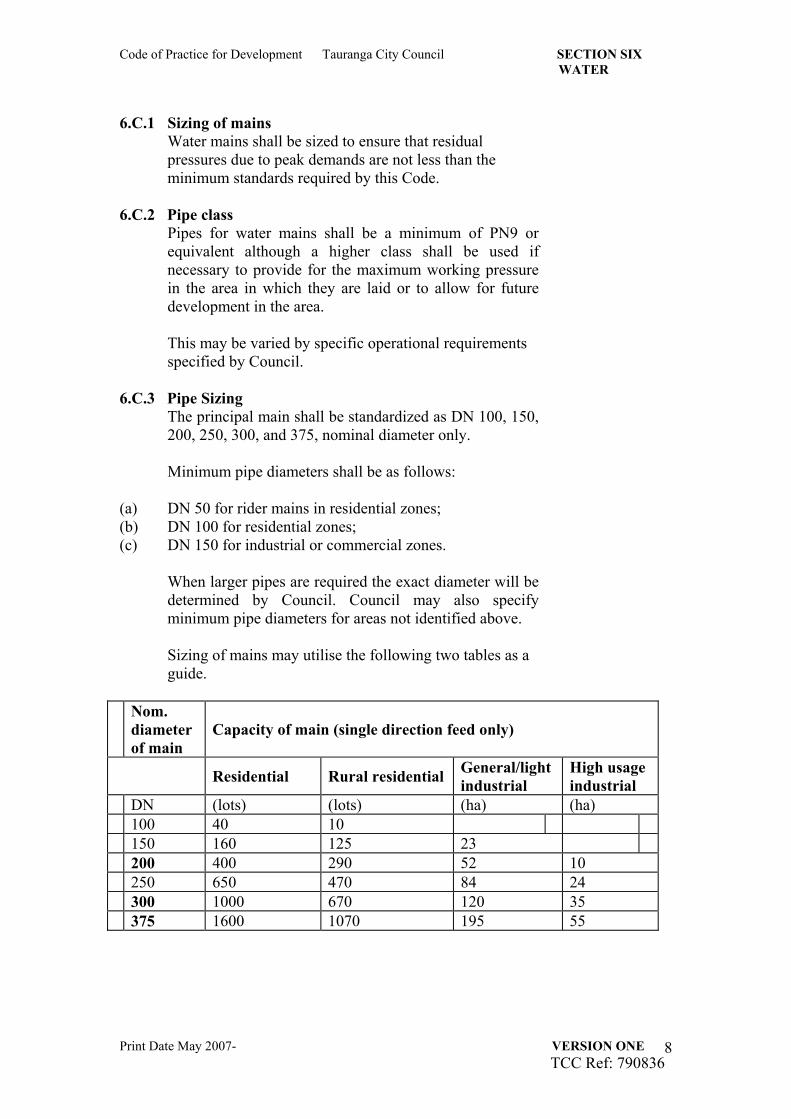
6.C.3 Pipe Sizing The principal main shall be standardized as DN 100, 150, 200, 250, 300, and 375, nominal diameter only.
Minimum pipe diameters shall be as follows:
(a) DN 50 for rider mains in residential zones; (b) DN 100 for residential zones; (c) DN 150 for industrial or commercial zones.
When larger pipes are required the exact diameter will be determined by Council. Council may also specify minimum pipe diameters for areas not identified above.
Sizing of mains may utilise the following two tables as a guide.
Nom. diameter of main
Capacity of main (single direction feed only)
Residential Rural residential General/light industrial
High usage industrial
DN (lots) (lots) (ha) (ha) 100 40 10 150 160 125 23 200 400 290 52 10 250 650 470 84 24 300 1000 670 120 35 375 1600 1070 195 55
Code of Practice for Development Tauranga City Council SECTION SIX WATER
Print Date May 2007- VERSION ONE TCC Ref: 790836
9
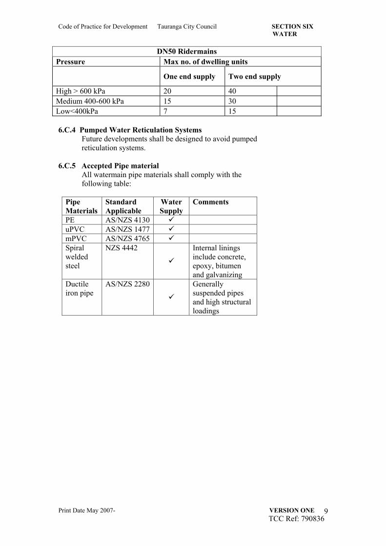
DN50 Ridermains Pressure Max no. of dwelling units
One end supply Two end supply
High > 600 kPa 20 40 Medium 400-600 kPa 15 30 Low<400kPa 7 15 6.C.4 Pumped Water Reticulation Systems
Future developments shall be designed to avoid pumped reticulation systems.
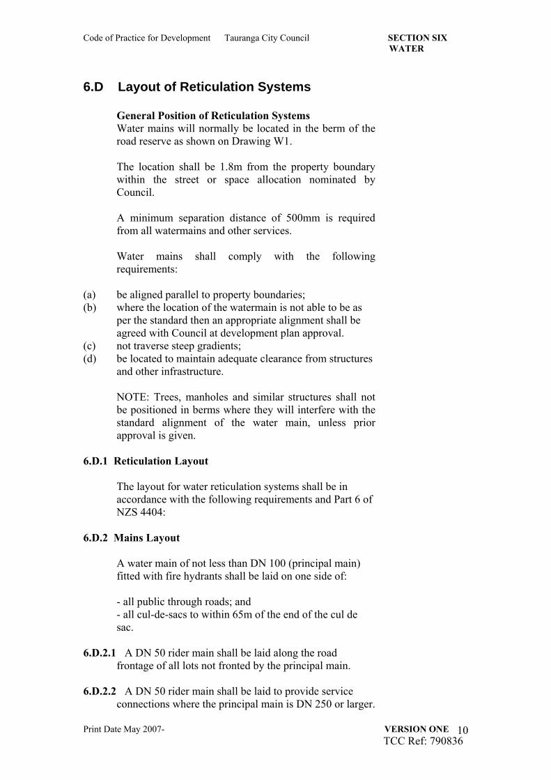
6.C.5 Accepted Pipe material
All watermain pipe materials shall comply with the following table:
Pipe Materials
Standard Applicable
Water Supply
Comments
PE AS/NZS 4130 uPVC AS/NZS 1477 mPVC AS/NZS 4765 Spiral welded steel
NZS 4442
Internal linings include concrete, epoxy, bitumen and galvanizing
Ductile iron pipe
AS/NZS 2280
Generally suspended pipes and high structural loadings
Code of Practice for Development Tauranga City Council SECTION SIX WATER
Print Date May 2007- VERSION ONE TCC Ref: 790836
10
6.D Layout of Reticulation Systems
General Position of Reticulation Systems Water mains will normally be located in the berm of the road reserve as shown on Drawing W1. The location shall be 1.8m from the property boundary within the street or space allocation nominated by Council. A minimum separation distance of 500mm is required from all watermains and other services. Water mains shall comply with the following requirements:
(a) be aligned parallel to property boundaries; (b) where the location of the watermain is not able to be as
per the standard then an appropriate alignment shall be agreed with Council at development plan approval.
(c) not traverse steep gradients; (d) be located to maintain adequate clearance from structures
and other infrastructure. NOTE: Trees, manholes and similar structures shall not be positioned in berms where they will interfere with the standard alignment of the water main, unless prior approval is given.
6.D.1 Reticulation Layout The layout for water reticulation systems shall be in accordance with the following requirements and Part 6 of NZS 4404:
6.D.2 Mains Layout
A water main of not less than DN 100 (principal main) fitted with fire hydrants shall be laid on one side of: - all public through roads; and - all cul-de-sacs to within 65m of the end of the cul de sac.
6.D.2.1 A DN 50 rider main shall be laid along the road frontage of all lots not fronted by the principal main.
6.D.2.2 A DN 50 rider main shall be laid to provide service connections where the principal main is DN 250 or larger.
Code of Practice for Development Tauranga City Council SECTION SIX WATER
Print Date May 2007- VERSION ONE TCC Ref: 790836
11
6.D.2.3 The principal mains serving industrial and commercial
areas shall be at least DN 150 laid on both sides of the street. (This requirement may be relaxed in short cul-de-sacs as long as adequate fire fighting coverage is available.)
6.D.2.4 In the case of arterial and dual carriageway streets
Council may require principal mains to be laid both sides of the street or road.
6.D.2.5 In industrial and commercial areas the minimum
requirement is for a DN 150 or DN 200 principal main on one side of the street, with an additional principal main on the other side.
6.D.3 Pipe Depths (Cover)
Both the principal main and rider mains shall have the following minimum cover, except in circumstances requiring special protection. Note: Greater depth require prior approval from Council.
(a) Under grass berms and footpaths (to top of pipe): - 800mm below finished surface (max. one metre)
(b) Under carriageway (to top of pipe): - One metre below finished surface (max. 1.2m) The section of the main adjacent to a carriageway crossing shall be gradually deepened, to allow the required cover under the carriageway without the provision of vertical bends. Similar provision shall be made to give the necessary cover over valve spindles, ie 150mm minimum cover.
(c) Service connections shall have 500mm cover (± 50mm) below finished surface - from the main to within 500mm of the road-side edge of the meter box, then 320mm cover through the water meter box.
6.D.4 Trench Widths Pipe trench width design considerations shall be based on the minimum side clearances detailed in the NZS4404, Appendix A, drawing CM-001.
6.D.5 Alignment Tolerances
Horizontal: + 100mm Vertical: + 50mm
Code of Practice for Development Tauranga City Council SECTION SIX WATER
Print Date May 2007- VERSION ONE TCC Ref: 790836
12
Where the above tolerances are unable to be met then specific approval from Council is required.
6.D.6 Mains Intersections (a) At street intersections: 90o tees or 90o bends are required rather than two 45o bends with a short length of pipe between them. (With the kerb to boundary widths and watermain alignments given in Drawing W1 and W2 90o tees or bends or both can normally be located between the kerb and boundary) (b) Where the principal main laid around a corner: 45o or similar bends shall be used. (Drawing W2 sets out the general principles, including the positioning of the valves)
6.D.7 Close Proximity Rules
The location of underground services affecting the proposed pipe alignment shall be determined. Where pipes will cross other services, the depth of those services shall be investigated, and exposed where necessary.
6.D.7.1 Clearance from Underground Services
(a) Where a pipe is designed in a road, the location of the pipe with respect to other services shall comply with SNZ HB 2002.
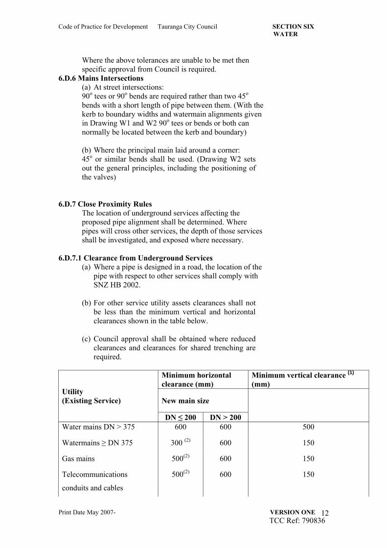
(b) For other service utility assets clearances shall not be less than the minimum vertical and horizontal clearances shown in the table below.
(c) Council approval shall be obtained where reduced
clearances and clearances for shared trenching are required.
Minimum horizontal clearance (mm)
Minimum vertical clearance (1) (mm)
New main size Utility (Existing Service)
DN ≤ 200 DN > 200
Water mains DN > 375 600 600 500
Watermains ≥ DN 375 300 (2) 600 150
Gas mains 500(2) 600 150
Telecommunications
conduits and cables
500(2) 600 150
Code of Practice for Development Tauranga City Council SECTION SIX WATER
Print Date May 2007- VERSION ONE TCC Ref: 790836
13
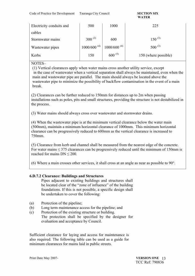
Electricity conduits and
cables
500 1000 225
Stormwater mains 300 (2) 600 150 (3)
Wastewater pipes 1000/600 (4) 1000/600 (4) 500 (3)
Kerbs 150 600 (5) 150 (where possible)
NOTES– (1) Vertical clearances apply when water mains cross another utility service, except in the case of wastewater when a vertical separation shall always be maintained, even when the main and wastewater pipe are parallel. The main should always be located above the wastewater pipe to minimize the possibility of backflow contamination in the event of a main break.
(2) Clearances can be further reduced to 150mm for distances up to 2m when passing installations such as poles, pits and small structures, providing the structure is not destabilized in the process. (3) Water mains should always cross over wastewater and stormwater drains. (4) When the wastewater pipe is at the minimum vertical clearance below the water main (500mm), maintain a minimum horizontal clearance of 1000mm. This minimum horizontal clearance can be progressively reduced to 600mm as the vertical clearance is increased to 750mm. (5) Clearance from kerb and channel shall be measured from the nearest edge of the concrete. For water mains ≤ 375 clearances can be progressively reduced until the minimum of 150mm is reached for mains DN ≤ 200. (6) Where a main crosses other services, it shall cross at an angle as near as possible to 90°.
6.D.7.2 Clearance: Buildings and Structures
Pipes adjacent to existing buildings and structures shall be located clear of the “zone of influence” of the building foundations. If this is not possible, a specific design shall be undertaken to cover the following:
(a) Protection of the pipeline; (b) Long term maintenance access for the pipeline; and (c) Protection of the existing structure or building.
The protection shall be specified by the designer for evaluation and acceptance by Council.
Sufficient clearance for laying and access for maintenance is also required. The following table can be used as a guide for minimum clearances for mains laid in public streets.
Code of Practice for Development Tauranga City Council SECTION SIX WATER
Print Date May 2007- VERSION ONE TCC Ref: 790836
14
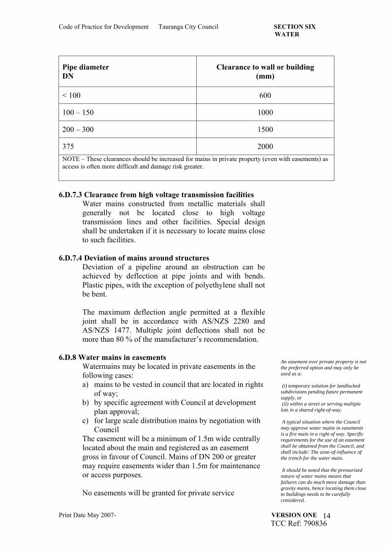
Pipe diameter DN
Clearance to wall or building (mm)
< 100 600
100 – 150 1000
200 – 300 1500
375 2000 NOTE – These clearances should be increased for mains in private property (even with easements) as access is often more difficult and damage risk greater.
6.D.7.3 Clearance from high voltage transmission facilities
Water mains constructed from metallic materials shall generally not be located close to high voltage transmission lines and other facilities. Special design shall be undertaken if it is necessary to locate mains close to such facilities.
6.D.7.4 Deviation of mains around structures Deviation of a pipeline around an obstruction can be achieved by deflection at pipe joints and with bends. Plastic pipes, with the exception of polyethylene shall not be bent. The maximum deflection angle permitted at a flexible joint shall be in accordance with AS/NZS 2280 and AS/NZS 1477. Multiple joint deflections shall not be more than 80 % of the manufacturer’s recommendation.
6.D.8 Water mains in easements Watermains may be located in private easements in the following cases: a) mains to be vested in council that are located in rights
of way; b) by specific agreement with Council at development
plan approval; c) for large scale distribution mains by negotiation with
Council The easement will be a minimum of 1.5m wide centrally located about the main and registered as an easement gross in favour of Council. Mains of DN 200 or greater may require easements wider than 1.5m for maintenance or access purposes. No easements will be granted for private service
An easement over private property is not the preferred option and may only be used as a: (i) temporary solution for landlocked subdivisions pending future permanent supply, or (ii) within a street or serving multiple lots in a shared right-of-way. A typical situation where the Council may approve water mains in easements is a fire main in a right of way. Specific requirements for the use of an easement shall be obtained from the Council, and shall include: The zone-of-influence of the trench for the water main. It should be noted that the pressurized nature of water mains means that failures can do much more damage than gravity mains, hence locating them close to buildings needs to be carefully considered.
Code of Practice for Development Tauranga City Council SECTION SIX WATER
Print Date May 2007- VERSION ONE TCC Ref: 790836
15
connections.
6.D.9 Shared trenching Where shared trenching is approved by Council and utility service owners, a detailed design shall be submitted for approval by those parties subject to the minimum clearance shown in design W1. Where approved by Council and utility service owners, shared trenching may also be used for property service connections.
6.D.10 Saline and Contaminated Areas Where a reticulation main is to be located on or near saline or contaminated land Council will require the following:
(a) Options to de-contaminate or de salinate the area; (b) Selection of appropriate pipeline materials and jointing
techniques to maintain water quality; (c) Selection of pipeline materials to achieve the required life
expectancy of the pipeline; (d) Safety of construction and maintenance personnel; (e) Special pipeline maintenance considerations.
6.D.11 Trenchless Techniques Trenchless technology may be required by Council for alignments in the following areas:
(a) Environmentally sensitive areas; (b) Built-up or congested areas to minimize disruption and
reinstatement; (c) Railway and major road crossings; (d) Significant vegetation; (e) General streets and vehicle crossings.
The following details including location of access pits and exit points will be submitted to Council for approval and development plan approval:
(i) Clearances from services and obstructions; (ii) The depth at which the pipeline is to be laid to ensure
minimum cover is maintained; (iii) The pipe support and ground compaction; (iv) How pipes will be protected from damage during the
work; (v) Any assessed risk to abutting surface and underground
structures.
Damage is a particular risk for plastic pipes or coated pipes in areas where the soils are known to be abrasive.
Code of Practice for Development Tauranga City Council SECTION SIX WATER
Print Date May 2007- VERSION ONE TCC Ref: 790836
16
6.E System Restraints
General Requirement Anchor or thrust blocks shall be provided at all bends, tees, pipe reducers, valves, dead (blank) ends and hydrants (located on MDPE pipe).
6.E.1 Thrust Blocks Thrust blocks shall be designed to resist the total unbalanced thrust and transmit all loads to the adjacent ground. Calculation of the unbalanced thrust shall be based on the maximum test pressure, or as otherwise specified by Council. Typical contact areas for selected soil conditions and pipe sizes are shown in the NZS4404 Appendix A drawings WS-004 and WS-005. Thrust blocks for temporary works shall be designed to the requirements for permanent thrust blocks. For pipelines with design pressures exceeding 1.3 MPa, and pipelines > DN 375 see the Water Reticulation Code of Australia WSA 03.
6.E.2 Anchor Blocks
Anchor blocks shall be designed to prevent movement of pipe bends in a vertical direction. They consist of sufficient mass concrete to prevent pipe movement (see the NZS4404 Appendix A drawing WS-005).
6.E.3 Restrained joint water mains Commercial mechanical restrained joint systems may be used subject to the approval of Council.
The Council require the use of thrust and anchor blocks due to operational and maintenance requirements.
6.E.4 Bulkheads Refer to the grade and spacing standard requirement provided in the NZS4404 Part 4.3.3.14.
Code of Practice for Development Tauranga City Council SECTION SIX WATER
Print Date May 2007- VERSION ONE TCC Ref: 790836
17
6.F Ridermains
6.F.1 Right angle extension to principal main Where a rider main is to be extended at right angles to a
principal main, this shall normally be connected with a cast iron tee with a female threaded branch (or an elongated gibault joint, tapped) and with a brass valve socket, as shown in Drawing W3.
6.F.2 Extension along same alignment Where a rider main is to be extended along the same
alignment beyond the end of the principal main, it shall normally be connected with a similar cast iron tee (or elongated gibault joint) with an anchored blank end plate, and with a vertical socket and right angle brass bend, as shown on drawing W3.
6.F.3 Flushing points
Flushing points shall be installed at the end of DN 50 rider mains (see Appendix A drawing WS-002).
6.G Valves General
Siting valves shall take a holistic view of all existing infrastructure and proposed additions. Principles to be considered shall include:
(a) Valves shall be sited to provide the control (flow, pressure, isolation, diversion, etc.) required by the Council;
(b) Ready access to valves to enable their safe operation. Account shall be taken of traffic and other site peculiarities;
(c) Minimization of inconvenience to the public by avoiding clustering of surface fittings in the footpath at intersections;
(d) Optimization of the number and location of valves and hydrants to meet Council’s operation and maintenance requirements, safe working and to minimize the effect of a shut down on Council’s customers.
Typical valve installation and chamber details are shown in drawings W2, W4, W7 and W25.
Valves are used to: • Isolate reticulation mains from distribution mains; • Isolate smaller reticulation mains from larger reticulation mains; • Isolate planning zone boundaries, for example, industrial, residential or commercial; Subject to the above considerations, valve numbers shall be minimized.
Code of Practice for Development Tauranga City Council SECTION SIX WATER
Print Date May 2007- VERSION ONE TCC Ref: 790836
18
6.G.1 Valve types The valves on the principle main shall be resilient faced, anticlockwise closing to NZS/BS 5163 Class 1 BS 5163 or to AS 23638 (pressure rated 1600kPa). All valves shall be nylon coated to AS/NZS 4158.
6.G.2 Gate valves Gate valves DN ≤ 50 (peat valves) shall be clockwise closing to AS 2638:2. Buried gate valves shall be operated from above ground and shall be designed to facilitate the use of a standard key and bar. An extension spindle shall be incorporated as necessary to ensure the top of the spindle is 350 mm below the Finished Surface Level.
6.G.3 Butterfly valves Butterfly valves shall only be used with the approval of the Council.
Butterfly valves are not normally used in reticulation mains as they hinder swabbing operations.
6.G.4 Valves for Principal Mains In the reticulation network, valves are used to limit the size of the shut-off area when a main is taken out of service for operational purposes. Valves ≥ DN 100 shall be nylon coated resilient seated anti-clockwise closing. In-line valves shall be the same diameter as the reticulation main.
6.G.5 Location marking of valves
The location marking of valves shall be to NZS 4404 Appendix A drawing WS-006. Paint shall be to TNZ M7 1998
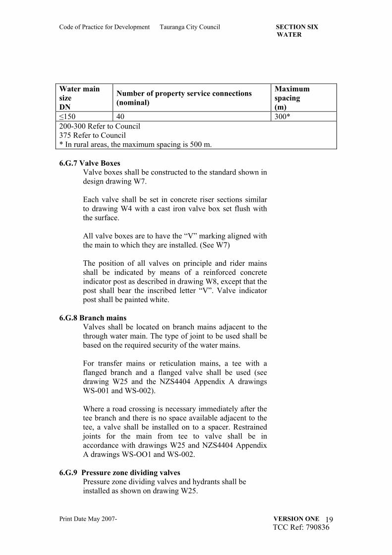
6.G.6 Valve Spacing Criteria The number of property service connections in a shut-off area shall be in accordance with the following table. When assessing property service numbers, unit title and strata title properties such as apartment buildings and multi-unit developments shall be counted as multiple connections. All connections having an alternative supply may be excluded when assessing property service numbers. The overriding maximum spacing between in-line valves shall be in accordance with the following table.
Code of Practice for Development Tauranga City Council SECTION SIX WATER
Print Date May 2007- VERSION ONE TCC Ref: 790836
19
Water main size DN
Number of property service connections (nominal)
Maximum spacing (m)
≤150 40 300* 200-300 Refer to Council 375 Refer to Council * In rural areas, the maximum spacing is 500 m. 6.G.7 Valve Boxes
Valve boxes shall be constructed to the standard shown in design drawing W7. Each valve shall be set in concrete riser sections similar to drawing W4 with a cast iron valve box set flush with the surface. All valve boxes are to have the “V” marking aligned with the main to which they are installed. (See W7) The position of all valves on principle and rider mains shall be indicated by means of a reinforced concrete indicator post as described in drawing W8, except that the post shall bear the inscribed letter “V”. Valve indicator post shall be painted white.
6.G.8 Branch mains Valves shall be located on branch mains adjacent to the through water main. The type of joint to be used shall be based on the required security of the water mains. For transfer mains or reticulation mains, a tee with a flanged branch and a flanged valve shall be used (see drawing W25 and the NZS4404 Appendix A drawings WS-001 and WS-002). Where a road crossing is necessary immediately after the tee branch and there is no space available adjacent to the tee, a valve shall be installed on to a spacer. Restrained joints for the main from tee to valve shall be in accordance with drawings W25 and NZS4404 Appendix A drawings WS-OO1 and WS-002.
6.G.9 Pressure zone dividing valves Pressure zone dividing valves and hydrants shall be installed as shown on drawing W25.
Code of Practice for Development Tauranga City Council SECTION SIX WATER
Print Date May 2007- VERSION ONE TCC Ref: 790836
20
6.G.10 Secure Service Connections Additional valves may be provided at a service connection to a customer requiring a greater security of supply such as hospitals and large industrial or commercial developments. Drawing W2 illustrates typical arrangements to facilitate partial isolation of the main while maintaining supply to the customer.
6.G.11 Pressure Reducing Valves (PRV) Pressure reducing valves are outside the scope of this Code. Design principles are based on NZS 4404 Part 6. The use of air valves require the written consent of Council.
A PRV is used to reduce the pressure upstream of the PRV to a desired lower downstream pressure. The PRV works automatically to maintain the desired downstream pressure. .
6.G.12 Air Valves (AV) Air valves require specific design and engineering approval. Design principles are based on NZS 4404 Part 6. The use of air valves require the written consent of Council.
Water mains with only a few service connections or a configuration that leads to air accumulation may require combination air valves to automatically remove accumulated air that may otherwise cause operational problems in the water system. The configuration of the distribution network in terms of both the change in elevation and the slope of the water main governs the number and location of air valves required.
6.G.13 Scour Valves and pump-out branches Scour valves and pump-out branches require specific design and engineering approval. Design principles are based on NZS 4404 Part 6. The use of scour valves and pump-out branches require the written consent of Council.
On mains DN > 300, scours are more effective In draining and provide greater flushing velocities than hydrants.
Code of Practice for Development Tauranga City Council SECTION SIX WATER
Print Date May 2007- VERSION ONE TCC Ref: 790836
21
6.H Hydrants 6.H.1 General
Hydrants are installed in reticulation systems for fire fighting and/or operational purposes. Operational purposes include mains flushing, chlorination and to allow the escape of air during charging and the release of water during dewatering of the water main, where air valves and scours are not installed. Hydrants shall be screw-down type to NZS/BS 750 clockwise closing. The use of ball hydrants is not permitted. All hydrants are to be nylon coated to AS/NZS 4158. Drain holes for frost protection are not permitted. If the hydrant is drilled for this purpose, the hole shall be plugged.
6.H.2 Hydrants (for fire fighting purposes) – Location and Spacing Requirements
a) Hydrants shall be spaced at intervals not exceeding
the following:
Residential areas 135m Commercial and Industrial areas 90m
Notwithstanding the above spacings hydrants shall be located in accordance with SNZ PAS 4509 Appendix G sG4.
b) As a minimum every building or building platform
required to be serviced by fire hydrants shall be located within 135m of a fire hydrant.
For clarity a building platform means any part of a front, corner or through site and that part of a rear site which excludes the access strip. The distance shall be measured along the route which a fire hose would normally be laid.
c) In cul-de-sac or other dead-end streets the last hydrant
shall be located at the end of the principal main but
Code of Practice for Development Tauranga City Council SECTION SIX WATER
Print Date May 2007- VERSION ONE TCC Ref: 790836
22
shall not be located further than 65m from the end of the street or cul de sac.
d) Where buildings or building platforms are located on
private rights of ways then a hydrant shall be located within 135m of any building or building platform.
e) Hydrants shall not be placed within 6m of any
building. f) Except for commercial areas, hydrants shall not be
offset into the roadway. g) Hydrants should be located within the berm. h) To avoid conflict with driveways, hydrants shall be
located opposite the lots’ common side boundary. 6.H.3 Hydrant installation
a) Fire hydrants shall not be fitted to reticulation mains
< DN 100 or to distribution, trunk or transfer mains without the prior written approval of Council.
b) Hydrant tees shall be flanged if laid next to other cast
iron fittings. Flexible joints are permitted (gibaults or spigot and socket rubber ring joints).
c) All hydrants connected to an MDPE pipe shall be
strapped to an approved anchor block. See s6.E.2.
d) Hydrant risers shall be used or the water main laid deeper, when required, to ensure that the top of the hydrant spindle is located between 100mm and 250mm below the finished surface level.
e) Where approved by Council, hydrants installed on
trunk mains will be fitted with an isolating valve. The tee will be positioned facing horizontal. All fittings shall be flanged.
6.H.4 Hydrants (for operational purposes) – Location and
Spacing Requirements Additional to fire fighting requirements, hydrants shall be located at:
(a) High points on reticulation mains to: - release air during charging; - allow air to enter the main when dewatering; and - facilitate manual release of any build up of air
AV’s are not normally required on reticulation mains in residential areas where the configuration of mains and service connections will usually eliminate small amounts of air accumulated during operation; Hydrants should be placed as close as possible to stop valves to facilitate maintenance activities such as cleaning of water mains. Apart from the fire fighting function, a
Code of Practice for Development Tauranga City Council SECTION SIX WATER
Print Date May 2007- VERSION ONE TCC Ref: 790836
23
where automatic combination air valves are not installed;
(b) Localized low points on water mains to drain the water
main where scour valves are not installed. (c) Where a scour valve is not provided at the end of any
main DN 100 or greater. (d) Adequate drainage facilities shall be provided to receive
the hydrant flows from dewatering and flushing operations.
hydrant also allows the section of dead end main to be flushed regularly to ensure acceptable on-going water quality. This is particularly important in new subdivisions where only a small number of properties maybe connected initially and where the main has been laid in a larger than required size with the expectation that it will be extended at a future date.
6.H.5 Hydrant Boxes 6.H.5.1 Manufacture and Installation The manufacture and installation of hydrant boxes shall
be as shown on drawing W4, W5 and W6. Hydrant boxes and risers should be fitted with lifting cleats to assist installation.
6.H.5.2 Location marking of Fire Hydrants The location and marking of fire hydrants shall be to SNZ PAS 4509 Appendix G subject to the following clarification.
• The lid and concrete surround is to be painted yellow to TNZ M7 standard.
• A triangle is required with its base located adjacent to the road centerline to MOTS and M section 4.07. A blue reflective marker shall be affixed to the pavement on the centerline to TNZ M12.
• In kerbed residential streets, the kerb shall be painted on both the face and top for a length of 500mm and a marker post is not required.
• Where a hydrant is located within the carriageway a circle around the hydrant formed to SNZ PAS 4509 Figure G1is required.
• In areas where there is no kerb is in place a concrete indicator post shall be installed 230mm from the lot boundary, immediately opposite the hydrant (Drawing W8).
Code of Practice for Development Tauranga City Council SECTION SIX WATER
Print Date May 2007- VERSION ONE TCC Ref: 790836
24
6.I Property Service Connections 6.I.1 Size
Property service connections shall conform to the following sizes: DN 20, DN 25, DN 50, DN 100. Larger connections are to be referred to Council.
The method of connection (including tapping) is dependent upon both the reticulation main and service connection pipe materials. The method adopted shall conform to:
(a) The NZS4404, Appendix A, drawing WS-003; (b) The requirements of Council.
6.I.2 Point of Supply (POS) to Consumer
For the ‘Point of Supply’ location for differing Lot configurations; - see drawings W27, W28 and W29 The point of supply to the consumer is determined by Council’s General Bylaw Part 8 – Supply of Water 2001 and shall be that point where ownership transfers from Council to the Consumer.
(a) In front lots (or dwelling units with individual street frontage) the P.O.S. shall be at the street boundary. The service pipe shall be terminated 300mm on the street side of the front boundary and where possible next to the electricity and telephone connections with a manifold incorporating a toby valve, a dual check valve meter; a meter and a service connection box all of a type approved by the Council (see Drawing W9).
(b) Back lots (or dwelling units without individual street
frontage) of up to two dwelling units shall have separate service connections at the street frontage, as in (a) above.
(c) In private ways serving 7 or more rear dwelling units a
50mm ID rider main shall be laid in the Right of Way with separate service connections off that rider main for each lot or dwelling. The connection manifold is to be within the right of way, adjacent to the lot served.
When fewer than 7 new lots are to be supplied, individual
Code of Practice for Development Tauranga City Council SECTION SIX WATER
Print Date May 2007- VERSION ONE TCC Ref: 790836
25
20mm service pipes and connections shall be installed at the road frontage, and individual private supply pipes laid from the Point of Supply to each dwelling. (Refer Council Bylaw) The rider main and service pipes, up to the point of supply, are to have easements in favour of Council over them. This requirement shall also apply to any development of a rear lot that results in three or more dwellings served by a single access, and may involve the removal of existing service pipes and the installation of new tobys and individual service pipes.
(d) The service connection is to have 500mm cover (± 50mm) from the main to within 500mm of the edge of the meter box and raise to 350mm cover through the meter box.
(e) Body Corporate and Multi Unit developments shall either
construct internal water mains and individual connections as per standard “greenfields subdivisional development” and vest these with easements in Council or install a bulk supply meter and backflow at the road frontage plus individual meters on the internal connections and retain supply in Body Corporate ownership. Refer to Council – Water Supply Bylaw for further details.
(f) Each Industrial / Commercial lot shall have the point of
metered supply service connection located as per (a) and (b) above except that for connections larger that 20mm diameter the backflow prevention system shall be located as near as practical to the property side of the boundary / R.O.W. (as applicable) and as close as practicable to the metered supply.
Developments with private roads including Papakianga housing, Maori roadways, retirement villages etc will also be treated as per (d).
6.I.3 Diameter and Pipe Materials (a) Service connections to individual dwellings shall be a
minimum of DN 20 (min. 12 bar PE) to AS/NZS4130.
(b) Connections to industrial and commercial properties shall be sized to meet the demand for the development or premise.
(c) Service connections up to DN 50 (min. 12 bar PE) to AS/NZS4130.
(d) Larger connections require specific approval from Council and will be subject to the conditions in the water connection consent.
Code of Practice for Development Tauranga City Council SECTION SIX WATER
Print Date May 2007- VERSION ONE TCC Ref: 790836
26
6.I.4 Tapping Bands (a) All service connections to principal main or rider
mains shall use a tapping band except for 50mm connections which shall use an elongated gibault.
(b) The tapping band for each service connection shall be
located near to the electricity and telephone connections for the allotment, and close to a side boundary.
(c) For rear sections: the tapping band shall located on
the dwelling side and clear of the driveway to the rear section.
(d) Tapping bands are to be dezinc resist cast bronze to
AS2345 or other approved material. (e) Connections greater than 50mm shall be made with a
tee junction and require the specific approval of Council.
6.I.5 Connections The connections shall be tested in conjunction with the mains. Service connections shall be laid at right angles to the boundary see drawing W28.
6.I.6 Service Connections (a) Service connection boxes, manifolds and backflow
preventers shall be of a type approved by Council and shall be installed at subdivision stage.
(b) Water meters shall be concentric meters to BS 5728
Part 7 with Class C metrological characteristics. The meter shall have a designation N2.5 for “Kent” manufactured meters and N1.5 for all other manufactured meters.
(c) The manifold shall fit within the locator clips fixed to
the meter box base. Refer drawing W10.
6.I.7 Metered Connection Location (a) Meter manifolds are to be located where customers
can easily locate the property isolating valve in the meter box in case of emergency.
(b) The service pipe for rear lots shall be located in the
ROW. (c) Service pipes located in easements are not permitted.
Code of Practice for Development Tauranga City Council SECTION SIX WATER
Print Date May 2007- VERSION ONE TCC Ref: 790836
27
6.I.8 Backflow Protection Backflow protection is required at the Point of Supply and as near as practical to the boundary. Any above ground device (Reduced Pressure Zone) is to be installed parallel to the front boundary. The level of protection is determined after surveying the occupancy of the property and to clause 3.3 “Cross Connection Hazards” in “The Approved Document for New Zealand Building Code” clause G12, Water Supply, Second Edition.
In industrial and commercial developments, approval may be given to omit service connections until the specific requirements of the consumer are known.
6.J Termination points 6.J.1 Mains Termination – Water Quality Termination points or dead ends should be avoided to
prevent poor water quality.
Alternative configurations such as a continuous network, link mains, looped mains and use of reticulation mains smaller than DN 100, particularly in cul-de-sacs, should be considered (see design drawing W24).
6.J.2 Mains Termination - Future Development (a) Water mains shall be laid to within one metre of the
boundary of a subdivision where the main is to be extended in the future.
(b) Temporary dead-end mains shall terminate with a
hydrant followed by a valve. The valve and hydrant shall be suitably anchored so that the future extension can be carried out without the need to disrupt services to existing customers.
(c) Where a development is staged mains shall be
constructed to terminate approximately 2 m beyond the finished road works to ensure that future works do not cause disruption to finished installations.
6.K Bends and Tees
At street intersections where PVC pipes are used 90° tees and 90° bends are preferable to 45° bends separated with a short length of pipe. When the degree of curvature cannot be obtained within normal joint tolerances, bends not sharper than 45° shall be used.
Code of Practice for Development Tauranga City Council SECTION SIX WATER
Print Date May 2007- VERSION ONE TCC Ref: 790836
28
6.L Construction of Pipelines 6.L.1 Excavation
(a) Excavation of existing carriageways shall conform to Council’s road opening procedures.
(b) Excavation in existing carriageways shall be carried out in a safe manner with the minimum disruption to traffic and/or pedestrians. (Refer S10 Street and Services Occupancy)
6.L.2 Bedding Pipes and fittings shall be surrounded with suitable bedding material in accordance with NZS 4404 Appendix A drawings CM-001 and CM-002.
6.L.3 Carriageway Trench Re-instatement (a) Pipelines located within carriageways the trench re-
instatement works shall follow the minimum requirements shown in drawing D16 and R32.
(b) Pipe trenches within a carriageway shall be backfilled using an approved hardfill placed immediately above the pipe surround and bedding and compacted in layers not exceeding 200mm in depth.
(c) In existing sealed streets, the top section of the trench shall be backfilled as specified by TNZ M/4.
(d) The depth of base course and type of finishing coat seal shall conform at least to the standard of the existing road construction or higher standard where required by Council.
6.L.4 Berms Pipe trenches under grass berms and footpaths shall be backfilled in accordance with the requirements of NZS 4404 Appendix A drawing CM-002.
6.L.5 Tracer wire When a pipe is installed by a directional drilling technique or bored through the ground for a distance exceeding 20 m, the pipe shall have a ‘tracer wire’ attached. This wire shall take the form of a continuous 2.5mm2 multi strand (polythene-sleeved) cable, strapped to the pipe wall by means of a minimum of two complete wraps of heavy duty adhesive tape, at a maximum of 3.0 m intervals. A tracer wire shall also be used on all MDPE pipes laid around curves.
Code of Practice for Development Tauranga City Council SECTION SIX WATER
Print Date May 2007- VERSION ONE TCC Ref: 790836
29
6.M Reservoirs and pumping stations
Require specific design and consultation with Council.
The Water Reticulation Code of Australia, WSA 03, contains design criteria for pumping stations.
6.N Water Quality
A number of factors in a network can adversely affect the quality of the water in the system. The network design shall ensure that the water quality at each property complies with the DWSNZ.
6.N.1 Materials All parts of the water supply system in contact with drinking water shall be designed using components and materials that comply with AS/NZS 4020. The pipe material selected shall ensure minimal impact on water quality within the system.
6.N.2 Prevention of back siphonage Drinking water supply systems shall be designed and equipped to prevent back siphonage. The location and operation of hydrants, air valves and scours shall ensure no external water enters the system. NOTE—Council requires appropriate backflow protection at the point of supply for all connections dependent on the hazard rating of the use, refer to section 6.J.8. Any above-ground backflow devices shall be installed parallel with the property boundary.
6.N.3 Water Age Drinking water supply systems shall be designed to minimize water age to ensure no unacceptable deterioration of water quality.
(a) Mains with dead ends shall be avoided by the provision of linked mains or looped mains. Particular care shall be taken at the boundaries between supply zones where dead ends shall be minimized.
(b) Mains for short runs shall be reduced in size or looped e.g. cul-de-sacs (see design drawing W24)
6.O System Test Pressure
(a) The system pressure acceptance test will be
Code of Practice for Development Tauranga City Council SECTION SIX WATER
Print Date May 2007- VERSION ONE TCC Ref: 790836
30
undertaken after completion of construction of the system including all water connections. The acceptance test will be undertaken prior to connecting to any existing vested reticulation system.
(b) Before undertaking the acceptance test the system being tested will have been filled with water and held at local mains pressure for at least 24 hours. The system shall then be pre-tested by the Contractor in the presence of the Consent Holder’s representative to confirm that the system meets the required acceptance test prior to contacting Council for observation of the final acceptance test.
(c) Each section of the reticulation system shall be tested by the developer in the presence of the Consent Holder’s Representative and a representative from Council. The test shall be conducted by the Consent Holder’s representative and the Contractor with all test equipment supplied by the same.
Test The reticulation system being tested shall meet the following minimum pressure: - 1400 kPa measured at the lowest point of the
reticulation system under test; or - at least 1.5 times the working pressure at any point
within the system whichever is greater. The pressure shall be maintained for a period of at least 15 minutes. During the period of the test leakage from the system under test shall not exceed one litre/ten mm pipe diameter/km length of pipeline/hr. (d) Council may require a more rigorous test of
reticulation system constructed from PE pipe materials. The test required is specified in Appendix B of NZS4404 sB2.
6.P System Disinfection
After backfilling and before being put into service, all pipes, valves, house connections and other fittings shall be disinfected. Disinfection of the water mains shall be carried out following successful pressure testing and backfilling as specified in Council’s Hygiene Code of Practice.
Code of Practice for Development Tauranga City Council SECTION SIX WATER
Print Date May 2007- VERSION ONE TCC Ref: 790836
31
The disinfection solution shall be collected and disposed of in an appropriate manner.
6.Q Connection of New Mains to Existing
Mains
6.Q.1 Temporary Access to Mains Water During development construction access to an existing watermain for the purposes of irrigation, dust control, road construction, pipe testing (stormwater, sewer or water) is allowed where the following occurs. Access to the existing watermain shall be metered and undertaken by an Approved Contractor.
6.Q.2 Connection of new mains to existing networks (a) In addition to the requirements of s2.8 of this Code
“Connection to Existing Water Networks/Approved Contractors” once the new asset network has successfully passed the final acceptance tests and inspections the consent holder will be issued with a Water Connection Consent. The consent is then provided to an approved contractor who, after undertaking and completing the connection of the new network to the existing network, complete the details required by the consent and returns the form to Council.
(b) When such connection to the existing network is
required the consent holder shall terminate the new main approximately 1m from the existing main at an appropriate level.
6.R Approved Contractors See section 2.8 of this Code