section 5: interactions of radiation with...
TRANSCRIPT

1
Section 5: Interactions of Radiation with Matter
All radiation is detected through its interaction with matter. This section will focus on what happens to a particle and its environment when radiation passes through matter, schematically
particle medium
The environment that the particle sees as it encounters the sea of electrons presented by matter is analogous to a space ship travelling through an asteroid belt (e.g. the Millenium Falcon in The Empire Strikes Back). The success of both the particle and the space ship will depend on the thickness and density of the electron sea/asteroid belt (without Han Solo to mavigate).
This subject has many practical applications, e.g. detection of radiation, radiation safety, environmental and biological hazards of radiation, and risk assessment. Four types of radiation are relevant to these discussions:
(1) Positive Ions: X+q e.g. α particles, fission fragments, cosmic rays, particle beams
(2) Electrons: β±, internal conversion and Auger electrons, cosmic rays
(3) Photons: γ → x-ray → uv → visible
(4) Neutrons: nuclear reactors, nuclear weapons, accelerators
Positive Ions
Positive ions are defined as cations, AX+q , where q is the atomic ionization state. Fig. 5.1 shows a calculations of the energy loss process as an ion stops in matter.
Fig. 5.1 Calculation of multiple collisions between positive ions (red) and atomic electrons of the medium as the ions pass through silicon.
2
The possible interactions of an ion in passing through matter are with either atomic electrons or nuclei. When one compares the ratio of cross sections σ (σ = probability) for such interactions, it is immediately apparent that particle-electron collisions dominate:
Possible interactions: Nuclei σ ~ 10−24 cm2
Orbital e−s σ ~ 10−16 cm2
The qualitative properties of charged particle-electron collisions are (1) the particle velocity is less than the velocity of light (vI < < c , usually ~ 0.01 − 0.1 c); (2) the mass of the cation is much greater than that of the electron, thus requiring multiple collisions to stop the ion (the bowling ball-ping pong ball effect), and (3) the cation trajectory is a nearly straight line up until the very end of its path. The average path length of the ion in the medium is defined as the range.
Three primary stages of energy-loss characterize the stopping process:
Electronic Stopping (vI >> ve-) – Electronic stopping accounts for about 95% of the distance traversed by the ion (its range) as it passes through matter. This process dominates as long as the velocity of the ion is much greater than the velocity of the atomic electrons of the medium. As it initially enters the electron sea presented by the medium, the atomic electrons of the ion are rapidly removed via electron-electron collisions, a process called stripping, as illustrated below
ZA qX+
→ → ZA ZX+
; e.g., 816 2O+
→ → 816 8O+
ion medium (electron sea)
For the general case, the charge of an energetic ion after stripping is equal to the atomic number of the ion. During electronic stopping the ion follows a nearly straight-line trajectory as it loses energy via sequential ion-electron collisions. As for the medium itself, each collision disrupts the internal atomic structure, creating additional cation-electron pairs, electronic excitation and molecular dissociation.
Intermediate stopping (vI ~ v1se-) – As the velocity of the particle decreases, it approaches the velocity of the innermost electrons of the medium, at which point the ion begins to pick up electrons from the stopping medium:
O +e-
v(1s)O e-
O e- O 8 7 5+ + + +⎯ →⎯⎯ ⎯ →⎯ ⎯ →⎯ → → →6 O± 1,0
1s1 1s2 1s22s1 1s22s22p4±
The 1s electrons (highest orbital velocity) are captured first, followed by capture of higher orbital electrons (2s, 2p, etc.) as the projectile slows down. During this stage the projectile undergoes moderate directional changes, slowing down with each additional electron pickup until the ion is approximately neutralized. As electrons are added to the ion, its size increases dramatically from nuclear to atomic dimensions.
Atomic Stopping (vI ~ vvalence e-) – In the final stage of stopping (end of the range) the ion is in a low ionization state or neutral and its size is comparable to that of the atoms in the stopping medium. The result is billiard-ball type collisions in which there are large directional changes
~ 10−8.
3
which lead to a distribution of ranges, or straggling, as shown in Fig.5.1. Thus the concept of range indicates an average distance travelled by an ion in the stopping process.
Energetics
The maximum energy loss ΔEmax of the particle in each particle-electron collision occurs when there is a head-on collision, or scattering to a center-of-mass angle of 180o. From energy and momentum conservation,
ΔEmax = 4 E0 (Me/Mion) = E0/459 Aion (MeV) . (Eq. 5.1)
Example : What is the maximum energy loss of a 6.000 MeV alpha particle ?
ΔEmax = 6.000 /459(4) = 0.003 MeV
∴E(α)′ = 6.000 −0.003 = 5.997 MeV ; i.e. stopping requires multiple collisions.
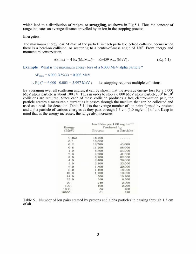
By averaging over all scattering angles, it can be shown that the average energy loss for a 6.000 MeV alpha particle is about 100 eV. Thus in order to stop a 6.000 MeV alpha particle, 104 to 105 collisions are required. Since each of these collision produces a free electron-cation pair, the particle creates a measurable current as it passes through the medium that can be collected and used as a basis for detection. Table 5.1 lists the average number of ion pairs formed by protons and alpha particle of various energies as they pass through 1.3 cm (1.0 mg/cm2 ) of air. Keep in mind that as the energy increases, the range also increases.
Table 5.1 Number of ion pairs created by protons and alpha particles in passing through 1.3 cm of air.

4
Rate of Energy Loss
The rate of energy loss, dE/dx, or specific ionization, is of great importance to numerous nuclear applications, ranging from detector technology to radiation therapy. The common unit for quantifying the rate of energyloss is defined as follows:
dE/dx = MeV/cm = ρMeV/(g/cm2) α MeV/(g/cm2).
Since density � is a constant, it is convenient to express the thickness x in terms of the more easily measurable quantity g/cm2 = x/�
As a schematic picture, assume a cation X+q is incident on a sea of electrons
X+q (E = E0) X+q (E = E’ X+q )
To calculate dE/dx, a multiple scattering picture is employed, resulting in the Bethe-Bloch Formula, given relativistically by the equation 5.2:
where v is the velocity of the ion,
m is the mass of the ion,
Z is the atomic number of the ion,
β = v/c,
I is the ionization potential of the absorber atoms,
n is the number of electrons per unit volume in the absorber, and
γ = q/Z.
For the non-relativistic case and fully-stripped ions (γ = 1), Eq. 5.2 simplifies to,
dE/dx = ΔE/ΔX α γAZion2/Eion = AZion
2/Eion (Eq. 5.3)
Eq. 5.3 is a valuable relationship in assessing energy loss in a detector, radiation damage and ionization density. It tells us that as the mass and charge of an ion increases, dE/dx increases. Thus a heavy ion such as carbon causes greater ionization than a proton of the same energy. Also, dE/dx decreases as the energy (and range) of an ion increases. For example, a 100 MeV proton causes less ionization than a 10 MeV proton, although the former has a much longer range.
⎥⎦
⎤⎢⎣
⎡−−−=− 22
2
2
42
)1ln(2ln4 ββπI
mvmv
neZdxdE

5
The result of Eqs. 5.2 and 5.3 is summarized by the Bragg curve, shown in fig. 5.2 in which the ionization created by an alpha particle is plotted versus its range (equivalent to its energy). As the range (energy) decreases, electronic stopping prevails and the ionization increases according to the 1/E factor in Eq.5.3, becoming very large as the particle nears the end of its range. Eventually, the γ factor in Eqs. 5.2 and 5.3 becomes important as the stopping process enters the atomic stopping regime. As the ion picks up electrons, γ goes to zero, as does the ionization.
The resulting peak, or Bragg peak, is a very important principle in radiation therapy. In treating a tumor with particle radiation, the objective is to select the energy such that the particle causes the maximum radiation damage to the diseased tissue. Thus, particle energy must be selected so that it stops in the region of the tumor, thereby destroying the maximum number of tumor cells. In addition, proper energy selection also minimizes the damage to the surrounding tissue, since the ionization is lower for more energetic particles.
Fig. 5.2 Bragg curve for the stopping of alpha particles in air. Note that a high range corresponds to high energy; i.e. when the range is zero, the particle has stopped.
Another expression of Eqs. 5.2 and 5.3 is illustrated in Fig.5.3, which shows the strong Z2 dependence of the energy-loss for several heavy-ions.

6
Fig. 5.3 Energy-loss results for heavy ions in aluminum. Several theoretical fits based on Eq. 5.2 are also shown.
For the purposes of detecting individual isotopes Eq. 5.3 can be applied in the form of two detectors, a thin transmission �E detector, followed by a detector that stops the particle; i.e. �E x E is proportional to AZ2.
Z, A, E ΔE E - ΔE
7
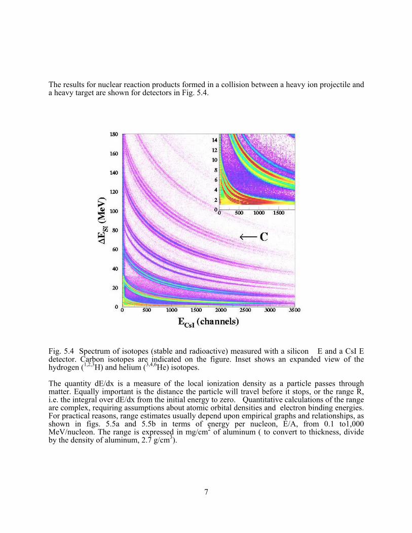
The results for nuclear reaction products formed in a collision between a heavy ion projectile and a heavy target are shown for detectors in Fig. 5.4.
Fig. 5.4 Spectrum of isotopes (stable and radioactive) measured with a silicon �E and a CsI E detector. Carbon isotopes are indicated on the figure. Inset shows an expanded view of the hydrogen (1,2,3H) and helium (3,4,6He) isotopes.
The quantity dE/dx is a measure of the local ionization density as a particle passes through matter. Equally important is the distance the particle will travel before it stops, or the range R, i.e. the integral over dE/dx from the initial energy to zero. Quantitative calculations of the range are complex, requiring assumptions about atomic orbital densities and electron binding energies. For practical reasons, range estimates usually depend upon empirical graphs and relationships, as shown in figs. 5.5a and 5.5b in terms of energy per nucleon, E/A, from 0.1 to1,000 MeV/nucleon. The range is expressed in mg/cm2 of aluminum ( to convert to thickness, divide by the density of aluminum, 2.7 g/cm3).

8
Fig. 5.5a Range-energy relationship in aluminum for E/A = 0.1 to 10 MeV protons and alpha particles. For energies between 7.0 and 10.0 MeV the lower curve (10-1) should be used and the result multiplied by 10.

9
Fig.13.5b Range-energy relationship in aluminum for E/A = 10 to 1,000 MeV protons and alpha particles. For energies between 370 and 1000 MeV the lower curve should be used and the result multiplied by 10.
Example: What thickness of aluminum is required to stop a 500 MeV proton? A 500 MeV alpha particle?
Proton: From Fig.5.5b the range of a 500 MeV proton is approximately 14,000 mg/cm2 x 10 = 140,000 mg/ cm2 = 140 g/cm2 = 140g/cm2/(2.7 g/cm3) = 52 cm
Alpha particle: E/A = 500MeV/4 = 125 MeV. From Fig.5.5b the range of an E/A = 125 MeV alpha particle is ~17,000 mg/cm2 =17g/cm2 =17 g/cm2/(2.7 g/cm3) =6.3cm. ______________________________________________________________________
To determine the ranges of other ions in aluminum, R(Zi, Ei, Ai), relative to protons, the following scaling law is useful, where Rp (Ei/Ai) is the range of a proton from Figs. 5.5ab.
R(Zi, Ei, Ai) = A ZpA Z
i2
p i2 Rp(Ei/AI) =
AZ
i
i2
⎛
⎝⎜⎜
⎞
⎠⎟⎟ Rp (Ei/Ai) (Eq. 5.4)
10
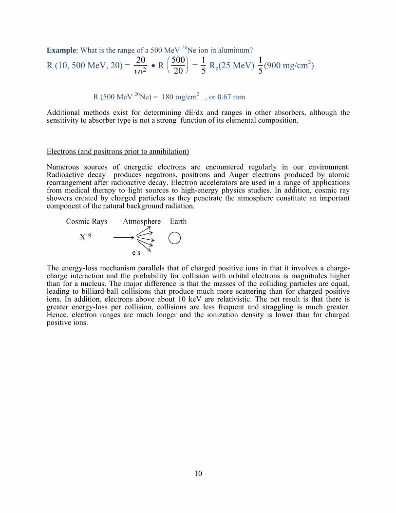
Example: What is the range of a 500 MeV 20Ne ion in aluminum?
R (10, 500 MeV, 20) = • R 50020
⎛⎝⎜
⎞⎠⎟ = 1
5 Rp(25 MeV) 15 (900 mg/cm2)
R (500 MeV 20Ne) = 180 mg/cm2 , or 0.67 mm
Additional methods exist for determining dE/dx and ranges in other absorbers, although the sensitivity to absorber type is not a strong function of its elemental composition.
Electrons (and positrons prior to annihilation)
Numerous sources of energetic electrons are encountered regularly in our environment. Radioactive decay produces negatrons, positrons and Auger electrons produced by atomic rearrangement after radioactive decay. Electron accelerators are used in a range of applications from medical therapy to light sources to high-energy physics studies. In addition, cosmic ray showers created by charged particles as they penetrate the atmosphere constitute an important component of the natural background radiation.
Cosmic Rays Atmosphere Earth
X+q
e-s
The energy-loss mechanism parallels that of charged positive ions in that it involves a charge-charge interaction and the probability for collision with orbital electrons is magnitudes higher than for a nucleus. The major difference is that the masses of the colliding particles are equal, leading to billiard-ball collisions that produce much more scattering than for charged positive ions. In addition, electrons above about 10 keV are relativistic. The net result is that there is greater energy-loss per collision, collisions are less frequent and straggling is much greater. Hence, electron ranges are much longer and the ionization density is lower than for charged positive ions.
20102

11
Range determinations of electrons can be obtained from empirical data, such as shown in Fig. 5.6 for an aluminum absorber.
Fig. 5.6 Range of electrons in an aluminum absorber.
Exercise: What is the range of a 10-MeV electron in aluminum?
From Fig.13.6, R = 5500 mg/cm2 = ~ 2 cm.
In contrast, the range for a 10-MeV alpha particle is 10 mg/cm2 = 0.004cm
______________________________________________________________________
For low-energy electrons, the range is not a strong function of the elemental composition of the absorber. However, for a relativistic electron ( v ~ c) its long range increases the probability that it will eventually pass close enough to a nucleus that it can interact with the nuclear charge. In this case the Coulomb interaction with the positively-charged nucleus bends the electron and in order to conserve momentum, energy in the form of a photon is radiated. This radiation is called bremsstrahlung (braking) radiation.

12
The energy of the photon, hν, depends on the Z of the nucleus, scattering angle and energy of the electron, E(hν) = f(Z, θ, Ee). The probability for energy loss due to bremsstrahlung radiation compared to ionization is strongly Z-dependent, given by
P (bremsstrahlung) = EZabs
P (ionization) 800 MeV ( Eq. 5.5)
Based on Eq. 5.5, high Z materials are good photon producers. For purposes of shielding high energy electrons, low-Z materials are best, since they stop primarily by ionization. Photons are more difficult to attenuate, as described in the next section. Light Sources create the same effect by passing an energetic electron beam through a magnetic field H. By adjusting the electron
h
e-
e-
νH
energy and the magnetic field, the frequency of the radiation can be fine-tuned. Light sources provide high intensity uv and x-ray photons that play a significant role in chemical, materials and biochemical research.
Electromagnetic Radiaton – Photons
The most pervasive type of radiation in our environment is electromagnetic radiation, photons – gamma rays from the rearrangement of nuclear orbitals, the spectrum from x-rays to ir radiation from rearrangement of atomic orbitals, cosmic ray showers, electron-positron annihilation and bremsstrahlung. Of particular concern are ultraviolet radiation from the sun, xrays and nuclear gamma rays. As the carrier of the electromagnetic force, photons, interact with all charged particles, again primarily with orbital electrons of the medium. There are three primary mechanisms of photon interactions with matter:
The Photoelectric Effect : Eγ e- (photon disappears)
Compton Scattering : Eγ Eγ ′ (photon is scattered)
e-

13
e−
Pair Production : Eγ ( e± pair produced )
e+
• The Photoelectric Effect
In the photoelectric effect one collision stops the photon. It disappears and all of its energy goes into the struck electron and the energy required to overcome the binding energy of the electron in the host atom, EB( nl) .
Ee− = Eγ − EB( nl) . ( Eq. 5.6)
When measured with a detector, the photoelectric effect produces a monoenergetic electron, giving rise to a sharp peak in the electron spectrum, or photopeak.. When the energy of the
γ e− (photoelectron); monoenergetic photopeak
photon is equal to or slightly greater than the electron binding energy, a resonance-like situation exists and the probability for absorbtion becomes very high, as illustrated later in this section. For photon energies well above the electron binding energy , the probability for absorbtion in the photoelectric effect PPE follows the relation
PPE ∝ Z5/ Eγ7/2(MeV) . (Eq. 5.7)
From Eq. 5.7 it is clear that the photoelectric effect is most efficient for low-energy photons incident on absorbers with high atomic numbers. Hence, lead makes an ideal absorber for protecting against low-energy photons.
• Compton Scattering
When the photon energy is well above electron binding energies, it becomes more probable for the photon to scatter off an electron, producing a photon degraded in energy and a recoil electron.
14
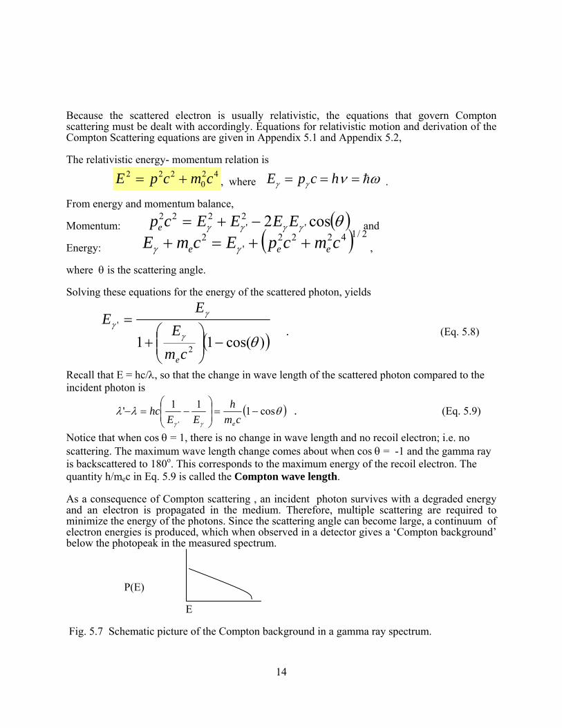
Because the scattered electron is usually relativistic, the equations that govern Compton scattering must be dealt with accordingly. Equations for relativistic motion and derivation of the Compton Scattering equations are given in Appendix 5.1 and Appendix 5.2,
The relativistic energy- momentum relation is
42
0222 cmcpE += , where ωνγγ h=== hcpE .
From energy and momentum balance,
Momentum: ( )θγγγγ cos2 '2'
222 EEEEcpe −+= and
Energy: ( ) 2/14222'
2 cmcpEcmE eee ++=+ γγ ,
where θ is the scattering angle.
Solving these equations for the energy of the scattered photon, yields
( ))cos(11 2
'
θγ
γγ
−⎟⎟⎠
⎞⎜⎜⎝
⎛+
=
cmE
EE
e
. (Eq. 5.8)
Recall that E = hc/λ, so that the change in wave length of the scattered photon compared to the incident photon is
( )θλλγγ
cos111''
−=⎟⎟⎠
⎞⎜⎜⎝
⎛−=−
cmh
EEhc
e
. (Eq. 5.9)
Notice that when cos θ = 1, there is no change in wave length and no recoil electron; i.e. no scattering. The maximum wave length change comes about when cos θ = -1 and the gamma ray is backscattered to 180o. This corresponds to the maximum energy of the recoil electron. The quantity h/mec in Eq. 5.9 is called the Compton wave length.
As a consequence of Compton scattering , an incident photon survives with a degraded energy and an electron is propagated in the medium. Therefore, multiple scattering are required to minimize the energy of the photons. Since the scattering angle can become large, a continuum of electron energies is produced, which when observed in a detector gives a ‘Compton background’ below the photopeak in the measured spectrum.
P(E) E
Fig. 5.7 Schematic picture of the Compton background in a gamma ray spectrum.

15
The probability for Compton Scattering PC is given by:
Pc ∝ Z/E . (Eq. 5.9)
As in the case of the photoelectric effect, the probability increases with the charge of the absorber, (more electrons in the atom’s ‘electron sea’), and decreases as the photon energy increases (the photon energy significantly exceeds the electron binding energies). However, in the case of Compton Scattering the dependence upon both Z and E is much weaker. The Compton effect is most effective for intermediate-energy (~ 1MeV) photons.
• Pair Production
When an energetic photon passes near a nucleus, the interaction with the nuclear charge Z can create an electron-positron pair, or pair production. In order to conserve mass the photon energy must exceed the mass of the electron and positron, so that pair production can only occur for photons with energies greater than the sum of the masses of the electron and positron, or 1.022 MeV. In a sense this process is similar to gamma decay, except that in this case the photon originates outside the nucleus rather internally as a consequence of nuclear rearrangement.
e+
e-
Stopping via pair production is a multi-step process. The photon first disappears and an electron-positron pair is produced. The electron then undergoes further stopping, as discussed in the previous section. Once thermalized in the stopping medium the positron captures an orbital electron, followed by annihilation to form two 0.511 MeV photons. These then undergo Compton scattering and/or the photoelectric effect to finally dissipate the initial photon energy.
Depending on photon energy the spectrum that one may observe in a nuclear detector may include all of these effects – a photopeak, Compton background and the photopeaks from the 0.511 MeV annihilation photons resulting from pair production.

16
Fig. 5.7 Spectrum of gamma rays observed in the decay of 40K. The photopeak at 1440keV is indicated in red. The Compton background is in blue. Annihilation radiation at 511 keV is shown in yellow. Peaks labeled SE (single escape) and DE (double escape) indicate pair production in which one or both of the electron/ positron pair escapes from the detector. These occur at energies of 1460 – 511 = 949 keV (SE) and 448 keV (DE).
Pair production is the only stopping mechanism that becomes more probable as the photon energy increases, as indicated by the probability relationship Ppp:
Ppp ∝ Z2 log Eγ (MeV) ; Eγ > 1.022 MeV (Eq.5.10)
The dependence on the absorber Z is also stronger than for Compton scattering, a consequence of the interation between the photon and the nuclear charge.
The relative importance of each of these three mechanisms is summarized in Fig. 5.8 for threedifferent elements. The Z dependence is of the photoelectric effect is apparent, as is the growing importance of pair production for high energy photons.
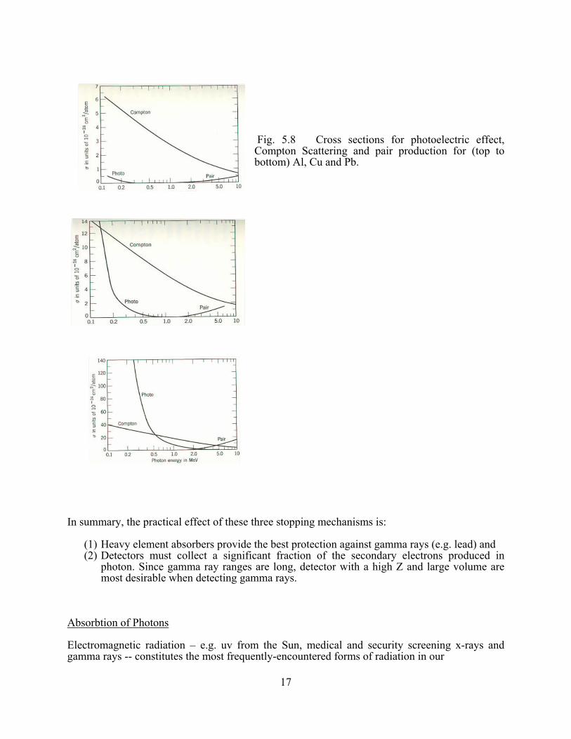
17
Fig. 5.8 Cross sections for photoelectric effect, Compton Scattering and pair production for (top to bottom) Al, Cu and Pb.
In summary, the practical effect of these three stopping mechanisms is:
(1) Heavy element absorbers provide the best protection against gamma rays (e.g. lead) and (2) Detectors must collect a significant fraction of the secondary electrons produced in
photon. Since gamma ray ranges are long, detector with a high Z and large volume are most desirable when detecting gamma rays.
Absorbtion of Photons
Electromagnetic radiation – e.g. uv from the Sun, medical and security screening x-rays and gamma rays -- constitutes the most frequently-encountered forms of radiation in our

18
environment. Due to the multiple stopping mechanisms involved in photon absorbtion, the mechanism is random. Thus, unlike the finite ranges of electrons and positive ions, photon ranges are indeterminate. Consequently photon intensity can only be attenuated, not fully eliminated. Instead of ranges, the probability of photon absorbtion is treated in terms of an absorbtion coefficient μ, where μ includes the combined contributions of the photoelectric effect, Compton scattering and pair production.
μ = μPE + μc + μpp
For random processes (recall radioactive decay) , the change in intensity I due to absorbtion in an absorber of thickness x is given by
−dI = μ I dx. ( Eq. 5.11)
For monoenergetic photons, integration of Eq. 5.11 yields the Beer-Lambert Law:
I = I0 e−μd , (Eq. 5.12)
where d is the absorber thickness. The amount of absorber required to reduce the intensity by one-half is the half-thickness d1/2, which is related to the absorbtion coefficient by
d1/2 = 0.693/μ (Eq. 5.13)
Absorbtion coefficients vary strongly with absorber type and and photon energy, as shown in Figs.5.8 and 5.9.

19
Fig 5.9 Plot of half-thickness versus photon energy for beryllium, aluminum, copper and lead. The discontinuities for lead at about 90 keV and at 9 keV for copper correspond to the 1s electron binding energy. The lower discontinuities for lead are dueto the 2s and 29 electron binding energies
In an environment where multiple photon sources may be present, modeling the photon attenuation can be quite complex. However, for well-defined sources such as x-rays or gamma rays, Eq. 5.12 is valuable for determining the amount of shielding required for radiation safety purposes. As an example, consider the critical absorbtion of x-rays – a subject of great relevance to both medical and dental practices. In order to illustrate critical absorbtion, a brief review of basic atomic nomenclature is required. For transitions described by the Bohr atom quantum numbers n and l, the following x-ray definitions apply:
Transitions to the n = 1, 2, 3 …levels are defined as K, L, M,…., respectively Transitions in which Δn = 1, 2, 3 … are labeled α, β, γ …., respectively Transitions involving Δl = 0, 1, 2 … are labeled 1, 2, 3……, respectively
Example:
A transition from the 2s to the 1s level 2s → 1s (the most common type) is called Kα1
Example: A transition from the 2s to the 1s level 2s → 1s (the most common type) is called Kα1
A transition from the 4p to the 2s level 4p → 2s is called Lβ2

20
Xrays are produced when there is a vacancy in an atomic orbit nl created by an external stimulus, e.g. and electron beam. This vacancy is subsequently filled by an electron from a higher orbit n′ l′,. The energy of an x-ray is determined by the difference in electron binding energies EB between the two atomic levels nl and n′ l′,
Exray = EB(nl) − EB(n′ l′ ) , where n < n′ . (Eq. 5.14)
Note that the x-ray energy Exray is always less than the binding energy of the electron in the lowest atomic level EB(nl). Thus energy conservation prevents an element from absorbing its own xrays. Photon absorbtion is always highest when the photon energy just exceed the binding energy of an electron in a given level (resonance effect).
Example: What is the best absorber for Zn Kα1 xrays? To answer this question, consider the following table of electron binding energy and xray energies:
Z = Fe Ni Cu Zn
EB (1s) 7.1 8.4 9.0 9.6
EB (2s) 0.8 0.8 0.9 0.9
EKα1 6.3 7.6 8.1 8.7
Critical absorber Zn Kα1 xray
Interpretation: Zn Kα1 xrays have an energy of 8.7 keV. In order for these xrays to be absorbed via the photoelectric effect, the binding energies of the absorber must be less than this value. Since the binding energy of the 1s electron in Zn and Cu are greater than 8.7 keV, they are not good absorbers. Ni on the other hand has a 1s binding energy of only 8.4 keV and therefore makes a good critical absorber. Fe and lighter elements would also be somewhat effective, but as is apparent from Fig.5.9, the maximum absorbing power occurs when the xray energy just exceeds the 1s electron binding energy of the absorber element.
Neutrons
Neutron sources are most commonly found in conjunction with fission reactors and nuclear particle accelerators. They may also occur in the cosmic ray flux and are copiously produced in thermonuclear explosions. Two properties of neutron govern their interactions with matter. First they have no charge. Thus ionization via electromagnetic interactions with atomic electrons is negligible, leaving only nuclear collisions as important sources of dissipating energy. Second, the mass of the neutron is comparable to the mass of the proton so that billiard-ball-type collisions lead to large scattering angles. Thus the concept of range is not an applicable.
The elimination of neutrons, which is a critical element of nuclear reactor design, is a two step process. In the first step the neutrons undergo thermalization via elastic and inelastic scattering from the absorber nuclei. Since the maximum energy loss for the neutron occurs when it scatters from a particle of identical mass (protons), light nuclei are most effective at reducing the neutron energy with the fewest collisions. When thermalized, the neutrons have the ambient average kinetic energy of their environment,
<Eth> = 3/2 kT, where k = 0.86 × 10⁻⁴ eV/K. (Eq.5.15)
keV

21
At a temperature of 300 K this corresponds to an average energy of <Eth> = 0.04 eV, or ~3 km/second. For a 1 MeV neutron the thermalization process requires about 20 collisions with hydrogen nuclei and about 200 for uranium nuclei.
Once thermalized, neutrons then disappear in the second step as a result of neutron capture (n,γ reactions) on absorber nuclei. The cross section dependence of very low energy neutrons on neutron energy is shown in Fig. 5.10.
Fig.5.10 Plot of neutron-capture cross sections as a function of neutron energy.
Two features of Fig 5.10 stand out. First, at the higher energies, sharp structure is observed in the spectrum. This effect is due to the capture of neutrons into specific nuclear energy levels populated in the n,γ reaction. At the lowest energies the cross section increases monotonically with decreasing energy, following a 1/v law, where v is the neutron velocity. For thermalized neutrons this is an important factor for efficient operation of nuclear reactors.
Choosing absorber materials for neutrons depends on whether one wishes to eliminate the neutrons for radiation safety purposes or whether they need to be preserved for efficient nuclear reactor operation. Neutron elimination is best accomplished with materials that have a very

22
high neutron capture cross section. Three important reactions for this purpose are: 10B + 1n 7Li + 4He : σ = 3838 b ;
113Cd + 1n 114Cd + γ ; σ = 2 × 10⁴ b;
157Gd + 1n 158Gd + γ: σ = 2.6 × 10⁵ b
Boron and cadmium play an important role as principal components of control rods in nuclear reactors, acting as a thermostat to remove neutrons if the fission rate becomes too high. Boron also finds application in neutron detectors since one of its reaction products is an alpha particle, which is an easily detected charged particle.
In order to prevent neutron loss from nuclear reactors and maximize efficiency, neutron preservation is desired. For this purpose one would like materials with very small cross sections for neutron capture reactions. Among these reactions are:
1n + 1H → 2H ; σ = 0.332 b
1n + 2H → 3H ; σ = 5.7 × 10⁻⁴ b
1n + 12C → 13C; σ = 3.4 10−3 b
1n + 16O ; σ = 1.8 10−4
Examination of these cross sections indicates that deuterated water or parafin should be effective materials for thermalizing neutrons with minimum loss due to reactions. For the purposes of constructing neutron detectors, hydrogenous materials are particularly useful since the scattering of neutrons from protons creates a charged particle that can be detected by conventional means.
Summary
In summary, an understanding of how radiation reacts with matter is highly relevant not only from the point of view of the physical and biological sciences, but also from the socio-political implications incumbent on the discussion of nuclear power, nuclear proliferation, and space travel.

23
Appendix 5.1
Relativistic relations for particles moving at velocities near the speed of light.
24
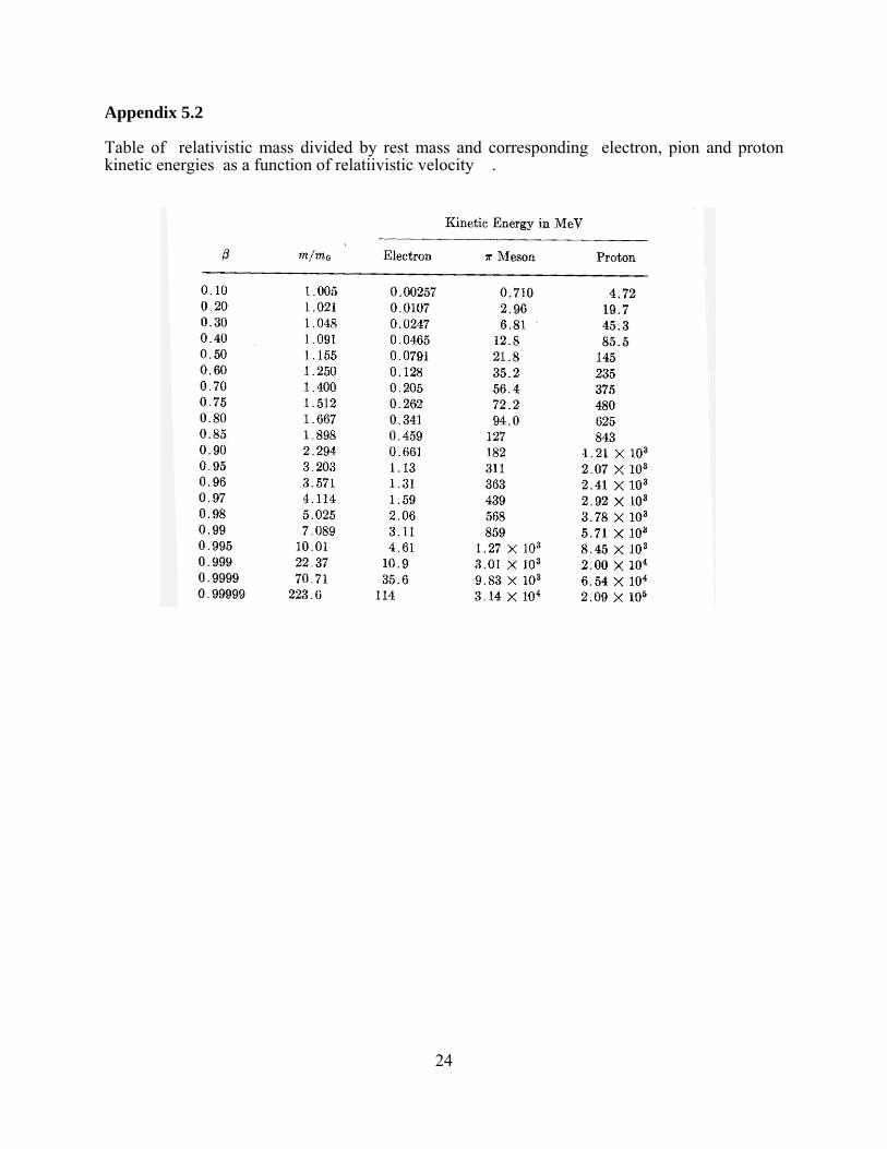
Appendix 5.2
Table of relativistic mass divided by rest mass and corresponding electron, pion and proton kinetic energies as a function of relatiivistic velocity �.

25

26

27