section 24 sign structures and panels 24 · section 24 sign structures and panels ... class 8.8 of...
TRANSCRIPT
SPECIFICATIONS FOR BRIDGE CONSTRUCTION
SECTION 24
SIGN STRUCTURES AND PANELS
TABLE OF CONTENTS
24.1 General ........................................................................................................................24-1
24.2 Sign Structures ..........................................................................................................24-1 24.2.1 Design ............................................................................................................24-1
24.2.1.1 Design Standards .........................................................................24-1 24.2.1.2 Design Notes and Drawings .........................................................24-2 24.2.1.3 Consultant Review........................................................................24-3
24.2.2 Supply and Fabrication...................................................................................24-4 24.2.2.1 Standards .....................................................................................24-4 24.2.2.2 Qualification ..................................................................................24-4 24.2.2.3 Engineering Data ..........................................................................24-4 24.2.2.4 Materials .......................................................................................24-5 24.2.2.5 Welding.........................................................................................24-5 24.2.2.6 Fabrication ....................................................................................24-7 24.2.2.7 Testing and Inspection..................................................................24-9 24.2.2.8 Identification Tag ........................................................................24-11
24.2.3 Erection ........................................................................................................24-11 24.2.4 Foundation ...................................................................................................24-13
24.3 Sign Panels ...............................................................................................................24-14 24.3.1 Shop Drawings .............................................................................................24-14 24.3.2 Materials .......................................................................................................24-15
24.3.2.1 Sheeting Materials ......................................................................24-15 24.3.2.2 Backing .......................................................................................24-15 24.3.2.3 Extruded Aluminum Preparation .................................................24-15 24.3.2.4 Application of Sheeting Materials ...............................................24-15
24.3.3 Construction .................................................................................................24-16
24.4 Measurement and Payment.....................................................................................24-16 24.4.1 Sign Structure...............................................................................................24-16 24.4.2 Sign Panels ..................................................................................................24-17
24.5 Warranty....................................................................................................................24-17
24.6 Drawing S-1682-03 Identification Plaque ...............................................................24-19

Specifications for Bridge Construction Section 24, Sign Structures and Panels
24 - 1
24.1 General
This specification is for the design, supply, fabrication, erection and all associated work pertaining to overhead and cantilevered sign structures and panels.
The underground utilities located on the drawings are approximate and are to be confirmed by the Contractor in the field.
Prior to design and construction, the Contractor shall confirm underground and overhead utility conflicts with the sign bases and support structure and immediately inform the Consultant of these conflicts. Any costs associated with addressing these underground utility conflicts shall be included in the bid price of the foundation.
24.2 Sign Structures
24.2.1 Design
24.2.1.1 Design Standards
The design shall be carried out by the Contractor. The Contractor's design engineer shall be a Professional Engineer registered to practice in the Province of Alberta under the APEGGA Act.
The design shall be in accordance with the requirements of AASHTO “Standard Specifications for Structural Supports for Highway Signs, Luminaires and Traffic Signals”, latest Edition and Interims, unless noted otherwise in these special provisions.
AASHTO equation 3-1, Clause 3.8.1, shall be modified as follows:
Pz = 2.7 q Kz Cd
where q shall be taken from CAN/CSA S6-06, Table A3.1.7 for a return period of 50 years.
The design ice thickness for ice accretion shall be the value given in CAN/CSA S6-06 Figure A3.1.4.
For the design of all cantilevered sign structures, the Fatigue Importance Factors in Table 11-1 shall be based on Fatigue Category I. The deflection for cantilevered sign structures, as specified in Clause 11.8, shall not exceed 200 mm.
Anchor bolts shall be post-tensioned to 0.70 Fpu. Stresses for anchor bolts shall be limited to 0.50 Fpu applied to the root tensile stress area for Group Load Combination I, II & III. Stress range for Group IV shall be in accordance with Section 11. The design shall allow for the failure of one anchor at any one location for each pile foundation. After such failure, the remaining anchors shall still be capable of meeting the above design requirements.
Design sign panel area shall be taken as the largest of:
(a) Actual sign panels shown on the drawings.
(b) Future sign panels shown on the drawings.
Specifications for Bridge Construction Section 24, Sign Structures and Panels
24 - 2
(c) Area of 3.5 m x 60% of horizontal span length, placed in any position along the span.
The structures shall have a permanent vertical camber of at least L/200.
The top of the concrete foundations shall project from 700 mm to 850 mm above the adjacent ground surface on the traffic side. The exposed portion of the concrete foundation shall be of circular cross-section.
The minimum vertical clearance below the sign panels shall be 6.0 metres.
24.2.1.2 Design Notes and Drawings
All design notes and shop drawings, shall be stamped, signed, and sealed by the Contractor's design engineer.
Two copies of the design notes and five copies of the shop drawings shall be submitted to the Consultant for review and acceptance at least three weeks in advance of scheduled fabrication.
The Contractor shall incorporate as-built conditions and re-submit all design notes and shop drawings, at the completion of construction.
(1) Design Notes Design notes shall be presented in a legible and logical format and shall be sufficiently detailed to allow a technical review of the design concepts and assumptions used in the design. The design notes shall include, as a minimum, calculations for the following:
(a) Design moment, shear and axial force envelopes for serviceability, ultimate and fatigue limit states.
(b) Columns
(c) Horizontal arm or truss
(d) Column or arm flange bolted connections
(e) All welded connections, stiffeners, etc.
(f) Anchor bolts
(g) Foundation
(2) Shop Drawings The shop drawings shall be legible and of adequate quality to be reproduced and microfilmed. All drawings shall be done on standard 11 x 17 or 22 x 34 sheet sizes.
The shop drawings shall include the following:
Specifications for Bridge Construction Section 24, Sign Structures and Panels
24 - 3
(a) Alberta Transportation Bridge File numbers, A-Ident numbers and project title, as provided by the Consultant, shall be shown on all the shop drawings.
(b) Design criteria meeting the requirements of section 24.2.1.1, for each individual sign structure, including:
• AASHTO “Standard Specifications for Structural Supports for Highway Signs, Luminaires and Traffic Signals” latest Edition and Interims
• Initial sign panel area and/or minimum design sign panel area • Design wind pressure • Fatigue category and fatigue loadings • Design ice thickness • Other dead loads • Design temperature range • Foundation soils parameters • Critical anchor bolt forces
(c) Each individual shop fabricated section or assembly shall be shown separately with complete and clearly identified welded or bolted details.
(d) Weld procedure identification shall be shown on the shop drawings in the tail of the weld symbols.
(e) All material splice locations shall be shown on the drawings.
(f) Complete material list.
(g) Erection procedure including tensioning procedure for anchor bolts.
24.2.1.3 Consultant Review
The design notes and drawings will be reviewed by the Consultant solely to ascertain conformance with codes and specifications. Responsibility of the final design remains solely with the Contractor. The Consultant's acceptance of the shop drawings shall not be construed as relieving the Contractor from his responsibility for errors or omissions in the calculations and drawings or for proper completion of the work in accordance with the contract.
After the Consultant review, the Contractor shall revise the drawings and calculations as required to the satisfaction of the Consultant without any additional cost to the Department.
Prior to commencing fabrication, all shop drawings shall be clearly signed by the Department’s Consultant as verification that the Consultant has completed his review and accepted the Shop Drawings. The Consultant's review and acceptance of the Shop Drawings will apply to general arrangements and details of design but not to figured dimensions or details of fabrication, and will be subject to the requirements of specifications and to such corrections as may be marked here on.

Specifications for Bridge Construction Section 24, Sign Structures and Panels
24 - 4
24.2.2 Supply and Fabrication
24.2.2.1 Standards
Fabrication of sign structures shall conform to “The American Association of State Highway and Transport Officials (AASHTO), Standard Specifications for Highway Bridges” and the American Welding Society (AWS) - Bridge Welding Code, D1.5.
Where imperial/metric conversions are necessary, The National Standard of Canada, CAN 3-Z234.1-79 shall be used as the basis of conversion.
All welding, cutting and preparation shall be in accordance with the American Welding Society (AWS) - Bridge Welding Code, D1.5, and D1.1.
24.2.2.2 Qualification
(1) Certification The Fabricator shall operate a recognized steel fabricating shop accepted by the Consultant.
The Fabricator shall be fully approved by the Canadian Welding Bureau (CWB) as per CSA Standard W47.1 in Divisions 1 or 2.
The Contractor shall notify the Department and Consultant of any subcontractors in his employ. The Contractor shall remain responsible for the work of the subcontractors. All terms of the contract, such as CWB approval and right of access shall apply to the subcontractor.
Only welders, welding operators and tackers approved by the Canadian Welding Bureau in the particular category shall be permitted to perform weldments. Their qualifications shall be current and available for examination by the Consultant.
(2) Contractor's Quality System The Contractor shall maintain acceptable quality management system throughout the contract. The purpose of the quality management system is to ensure that the product meets the quality requirements of the contract and is delivered on time. The Contractor's quality management system shall apply to all stages of the design, procurement, manufacturing, testing and delivery of the product.
24.2.2.3 Engineering Data
(1) Welding Procedures Welding procedures shall be submitted for each type of weld used in the structure. The procedures shall bear the approval of the Canadian Welding Bureau and shall also be reviewed by the Department prior to use on the structure.
(2) Proposed Fabrication Sequence Prior to commencement of fabrication, the Contractor shall present for review and acceptance an outline of the fabrication sequence that clearly describes the order of make-up and assembly of all the component parts, as well as shop assembly, inspection stations.
Specifications for Bridge Construction Section 24, Sign Structures and Panels
24 - 5
(3) Mill Certificates Mill certificates shall be provided for all material before fabrication commences.
(4) Schedules The Contractor shall provide and keep current a complete fabrication schedule in a form satisfactory to the Consultant.
24.2.2.4 Materials
(a) All materials shall be new
(b) The use of aluminum and aluminum alloy are not acceptable, unless specifically stated otherwise by the Consultant
(c) Structural steel plate material shall conform to CSA G40.21M 300W*
*Silicon content shall be less than 0.04% for the shafts, whereas for flanges and base plates the silicon content shall be either less than 0.04% or between 0.15 to 0.25%
(d) All bolts, nuts and washers shall conform to ASTM Standard A325 or shall meet property class 8.8 of the Industrial Fasteners Institute for metric high strength structural bolts, nuts and washers. Certified mill test reports for the fastener material shall be provided
(e) Anchor bolts shall be fabricated from DYWIDAG thread bars conforming to the requirements of CSA Standard G279
(f) All steel materials including all hardware and anchor bolts shall be hot-dip galvanized
24.2.2.5 Welding
(1) Filler Metals Low hydrogen filler, fluxes and low hydrogen welding practices shall be used throughout. The low hydrogen covering and flux shall be protected and stored as specified by AWS Standard D1.5. Flux cored welding or use of cored filler wires in the submerged arc process or shielding gas processes are not considered as conforming to low hydrogen practice. These methods will not be permitted. However metal core welding process utilizing low hydrogen electrodes with AWS designation of H4 will be allowed. The deposited weld metal shall provide strength, durability, impact toughness and corrosion resistance equivalent to base metal.
Field application of metal core arc welding is not allowed.
(2) Cleaning Prior to Welding Weld areas must be clean, free of mill scale, dirt, grease, and other contaminants prior to welding.
(3) Longitudinal Seams All longitudinal seams shall be made by an approved semi or fully automatic submerged arc or metal core welding processes.
Specifications for Bridge Construction Section 24, Sign Structures and Panels
24 - 6
(4) Weld Penetration The full penetration welds shall be completed using properly fitted backing bars or backgouged to sound metal. The longitudinal seams shall have a minimum 60% penetration; however if backing bar is used for longitudinal seam, the weld penetration shall be 90%. The following welds shall have 100% penetration:
(a) Column to base plate
(b) Member to flange plate
(c) Flange plate to gusset plate
(d) Longitudinal seam welds within 150 mm of circumferential welds and 150 mm beyond hand holes (when provided) shall be full penetration groove welds. Transition between full and partial penetration welds shall be ground smooth.
(e) Backing bar splices
The backing bar for full penetration weld shall be properly fitted and the member prepared to a sharp edged 45° chamfer. The groove weld shall be placed in a minimum of two passes by using 100°C of preheat (unless higher preheat is required as per AWS) and maintain a root opening of 5 mm. A rod size no greater than 4.0 mm shall be used for the first pass. A reinforcing fillet weld shall be placed all around the joint.
(5) Tack and Temporary Welds Tack and temporary welds shall not be allowed unless they are to be incorporated in the final weld. Tack welds, where allowed, shall be of a minimum length of four times the nominal size of the weld, and shall be subject to the same quality requirements as the final welds. Cracked tack welds shall be completely removed prior to welding over.
(6) Run-off Tabs Run-off tabs shall be used at the ends of all welds that terminate at the edge of a member. The tabs shall be a minimum of 100 mm long unless greater length is required for satisfactory work. They shall be tack welded only to that portion of the material that will not remain a part of the structure, or where the tack will be welded over and fused into the final joint. After welding, the tabs are to be removed by flame cutting, not by breaking off.
(7) Methods of Weldment Repair Repair procedures for unsatisfactory weldments shall be submitted for review and acceptance by the Department and Consultant prior to repair work commencing.
(8) Arc Strikes Arc strikes will not be permitted. In the event of accidental arc strikes, the Contractor shall submit to the Department and Consultant for review and acceptance a proposed repair procedure. The repair procedure shall include the complete grinding out of the crater produced by the arc strike. These areas will be examined by the Consultant to ensure complete removal of the metal in the affected area.
Specifications for Bridge Construction Section 24, Sign Structures and Panels
24 - 7
(9) Plug and Slot Welds Plug welds or slot welds shall not be permitted.
24.2.2.6 Fabrication
Fabrication shall be performed in a fully enclosed area which is adequately heated. The shop temperature shall be at least 10°C. Field welding will not be allowed.
(1) Pre-job Meeting A pre-fabrication meeting is required prior to commencement of fabrication of sign structures. The meeting will be held at fabricator’s plant and the Contractor shall ensure the plant superintendent and plant manager responsible for the work and any manufacturer’s representatives directly involved in the specialized work are in attendance. The Department/Consultant will conduct this meeting after the shop drawings have been approved and welding procedures have been reviewed. The Contractor shall provide two weeks notice to the Department/Consultant prior to the meeting.
(2) Cutting of Plate All plate material for main members and any plate material welded to the main member shall be flame cut using an automatic cutting machine. Shearing is not allowed.
Corners of plates and structural sections shall be ground to a 1 mm chamfer.
(3) Material Splices Additional splices, other than those shown on the shop drawings, will require acceptance of the Department and Consultant. The Contractor shall bear the cost of inspection of these splices.
(4) Additional Requirements (a) Each column, arm, extension, clamp and bracket shall be fabricated from one piece of sheet
steel unless accepted otherwise.
(b) Intermediate circumferential butt welds will not be allowed however horizontal members greater than 12 m span may have a bolted splice.
(c) Columns, arms, extensions and clamps shall be brake press formed or roll formed. The brake press knife shall have a radius suitable for the thickness of the material and nature of the bend.
(d) All plate edges shall be free of notches and gouges.
(e) The depth or projection of any imperfections on the inner or outer surfaces shall not exceed 15% of wall thickness. Any depth or projection up to 33% of wall thickness may be repaired by welding. Any excessive projecting weld metal shall be removed.
(f) The diameter of bolt holes in base plates shall be 10 mm larger than the bolt diameter.
(g) Punching of full size holes will not be permitted. The holes shall be circular and perpendicular to the member and shall be deburred to ensure a proper faying surface.
Specifications for Bridge Construction Section 24, Sign Structures and Panels
24 - 8
(h) Hand holes with cover plates on top and bottom of columns are to be provided for illuminated sign structures or when required as per special provisions.
(i) Hand hole (when required) shall be stiffened by providing a reinforcing rim with semi-circular ends. The rim shall be welded to the member with a full penetration groove weld supplemented with an all around fillet weld.
(j) Only low stress stamps shall be used for identification marks. The stamps and specific location shall be shown on the shop drawings and accepted by the Consultant.
(k) Stiffeners are not allowed on column to base plate and member to flange plate connections.
(5) Dimensional Tolerances All fabrication shall meet the tolerances described below:
(a) Straightness The straightness of any item shall not exceed the overall length divided by 300 from the surface at any point. This shall be measured with a straight line joining the surface at both ends. The difference between the straight line and the surface shall then be measured to determine the straightness.
(b) Twisting The twist in the overall length of any column, arm, or extension shall not exceed 7°.
(c) Length The specified length of any item shall be within 0 to 60 mm or 0 to +5% (whichever is less) with the exception of sign bridge spans which shall be within 5 mm of the specified dimensions in unloaded condition. The tolerance for height shall be - 0 to +60 mm.
(d) Across the Flat Dimensions The average of all across the flats dimensions from a given cross section shall be within 1% of the specified dimension. In addition, the ratio of the maximum to minimum across the flats dimensions shall be less than or equal to 1.05.
(e) Tolerance for Flatness of Base Plates and Flange Plates Surfaces of column base plates shall be flat to within 3 mm tolerance in 305 mm, and to within 5 mm tolerance overall. Faying surfaces of flange plates shall be flat to within 2 mm tolerance overall.
(f) Arm Rise Arm rises apply to unloaded structure in the standing position.
(6) Pre-Assembly After welding and fabrication, but prior to galvanizing, the Contractor shall pre assemble all structures complete with welded sign clamps to check the fit and geometry. Pre assembled structures shall be inspected by the Consultant.

Specifications for Bridge Construction Section 24, Sign Structures and Panels
24 - 9
Following inspection by the Consultant, the structures shall be disassembled for galvanizing.
(7) Galvanizing Galvanizing shall be by the hot dip method, after fabrication, in accordance with the current edition of ASTM A123/A123M Standard Specification for Zinc (Hot-Dip Galvanized) Coatings on Iron and Steel Products and ASTM A153/A153M Standard Specification for Zinc Coating (Hot-Dip) on Iron and Steel Hardware with additions and exceptions as described in this specification. The Fabricator shall provide a smooth finish on all edges and surfaces, and remove all weld spatter and all welding flux residue from the steel components prior to galvanizing. Lumps, globules or heavy deposits of zinc will not be permitted. All threaded holes or threaded couplings shall be retapped after galvanizing.
Repair of galvanizing shall only be done if bare areas are infrequent, small, and suitable for repair. A detailed repair procedure shall be submitted and accepted prior to its use. It should be noted that repairs may require complete removal of the galvanized coating and regalvanizing. Repair shall be in compliance with ASTM A780, Method A3 Metallizing. The thickness of the metallizing shall be 180 µm, and the repair tested for adhesion. The finished appearance shall be similar to the adjacent galvanizing. The Consultant will determine the acceptability of repaired areas.
(8) Base Plate Corrosion Protection The bottom face of each base plate shall be protected by a medium grey colour barrier coating accepted by the Consultant, to prevent contact between the zinc and the grout. The galvanized surface must be roughened prior to application of barrier coating. The surface preparation of the galvanized surface and the dry film thickness (DFT) of the coating shall be in accordance with the coating manufacturer's recommendations. The Consultant will test the adhesion of fully cured coating as per ASTM D3359 “Standard Test Methods for Measuring Adhesion by Tape Test”. The method selected for testing (Method A or B) shall depend on the dry film thickness of the coating. The coating manufacturer's product data sheets shall be provided to the Consultant prior to the application of the coating. The adhesion test result shall meet a minimum of “4B” classification (a maximum allowable flaking of 5%).
24.2.2.7 Testing and Inspection
(1) Access The Contractor shall provide full facilities for the inspection of material and workmanship. Free access shall be allowed to the Consultant to all parts of the works. When required by the Consultant, the Contractor shall provide needed manpower for assistance in checking layout and performing inspection duties.
(2) Testing by the Contractor The Contractor shall provide quality control throughout the course of fabrication. All test records made by the fabricating shop in the course of normal quality control shall be open to the Consultant for inspection. Testing and inspection made necessary by the repair of faulty work shall be paid for by the Contractor.
Specifications for Bridge Construction Section 24, Sign Structures and Panels
24 - 10
The Contractor shall arrange to have all full penetration welds inspected either by ultrasonic testing or radiographic inspection methods. Partial penetration seam welds shall be inspected by ultrasonic testing. The frequency of partial penetration weld inspections shall be three random locations per weld and the length of weld for ultrasonic inspection at each location shall be 200 mm. Calibration blocks for each thickness shall be prepared for ultrasonic testing to establish sensitivity levels and acceptance criteria. The NDT shall be done by a company certified to CAN/CSA W178.1. Ultrasonic and radiographic testing technicians shall be certified to Level II of CGSB. Ultrasonic testing procedure shall be submitted to the Consultant for review and acceptance prior to commencement of fabrication. A copy of test results shall be provided to the Consultant indicating the percentage of penetration. The Contractor shall not proceed to the next stage of fabrication until all the seam welds have passed the Quality Control and the results have been reviewed by the Consultant.
All costs associated with non-destructive inspection of partial and full penetration welds, preparation of calibration blocks, establishing sensitivity levels and acceptance criteria shall be the responsibility of the Contractor.
The Contractor shall be responsible for all travel, boarding and lodging costs for a Department’s representative to attend the prejob meeting and two additional trips during the course of fabrication when the sign structures are being fabricated outside the Province of Alberta.
(3) Testing by the Consultant The Consultant will perform visual inspection. Any additional NDT; such as radiographic, ultrasonic, magnetic particle and any other inspection that may be specified or required will be performed by the Consultant or by his testing agencies at the Consultant's expense.
(4) Inspection Station To insure that each stage of inspection is performed in an orderly manner, during the fabrication, Inspection Stations will be set up at specific points. Certain items of the work will then be checked, and deficiencies shall be corrected, prior to the work being sent to the next stage of fabrication. These check points are to be agreed to by the Department and Consultant and the Fabricator prior to commencement of fabrication. The Department and Consultant reserve the right to stop detrimental fabrication between check points if deemed necessary.
(5) Non-destructive Methods of Examination The methods of non-destructive examination shall be in accordance with the following standards: - Radiography - AWS Standard D1.5 - Ultrasonic - AWS Standard D1.5 - Magnetic Particle - ASTM Standard E-709
(6) Inspection Schedule All welds will be visually inspected. Ultrasonic or radiographic inspection will be performed on full penetration welds.

Specifications for Bridge Construction Section 24, Sign Structures and Panels
24 - 11
24.2.2.8 Identification Tag
The Contractor shall supply and install an identification tag on one column of each structure at 2.4 m above base plate. The column shall be drilled and tapped for 2 - 10 mm diameter attachment bolts. The Identification Tag shall be fabricated as per the attached drawing S-1682-03.
24.2.3 Erection
Any product damaged in shipping shall be replaced at no extra cost to the Department.
The Contractor shall not erect the structural steel until the substructure concrete has been cured a minimum of three days and achieved 80% of the 28 day specified concrete strength requirement.
All components shall be handled with care to prevent stress to the components through bending or twisting. The use of steel chains as slings shall not be permitted. Any damage to the components through overstress, scratching or denting shall be repaired or replaced at the Contractor's expense to the satisfaction of the Consultant.
The structure shall be set accurately on galvanized shim plates. The shim plates must be located so that a minimum of 75 mm of distance is provided from shims to grout edge. The method of forming and pouring the grout shall be submitted to the Consultant for review and acceptance. Dry pack methods of constructing grout pads will not be accepted.
Hand hole bolts shall be coated with anti seize lubricant.
The Contractor shall erect the sign structure in a manner that addresses all safety issues including the interim period between erection, grouting and post-tensioning.
(1) High Tensile Strength Bolted Connections Bolted parts shall fit solidly together when assembled. Contact surfaces shall be free of dirt, grease, burrs, pits and other defects that would prevent solid seating of the parts. Connections shall be assembled with a hardened washer under the bolt head or nut, whichever is the element turned in tightening. Surfaces of bolted parts in contact with the bolt head and nut shall be parallel.
Specifications for Bridge Construction Section 24, Sign Structures and Panels
24 - 12
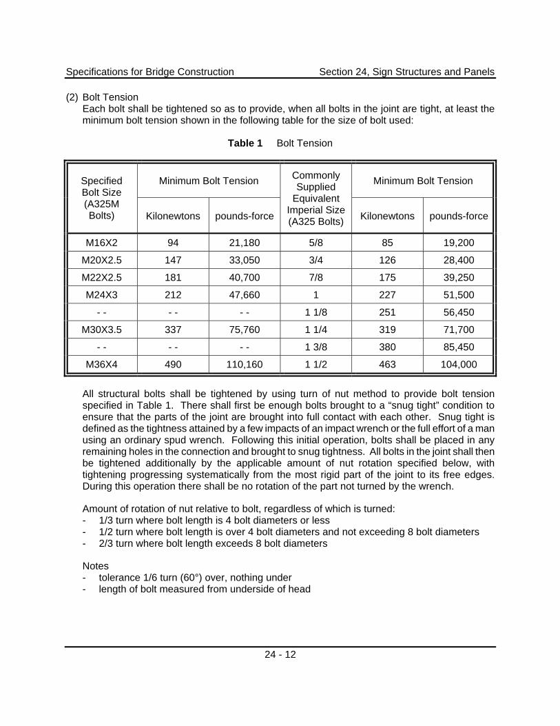
(2) Bolt Tension Each bolt shall be tightened so as to provide, when all bolts in the joint are tight, at least the minimum bolt tension shown in the following table for the size of bolt used:
Table 1 Bolt Tension
Minimum Bolt Tension Minimum Bolt Tension Specified Bolt Size (A325M Bolts) Kilonewtons pounds-force
Commonly Supplied
Equivalent Imperial Size (A325 Bolts) Kilonewtons pounds-force
M16X2 94 21,180 5/8 85 19,200
M20X2.5 147 33,050 3/4 126 28,400
M22X2.5 181 40,700 7/8 175 39,250
M24X3 212 47,660 1 227 51,500
- - - - - - 1 1/8 251 56,450
M30X3.5 337 75,760 1 1/4 319 71,700
- - - - - - 1 3/8 380 85,450
M36X4 490 110,160 1 1/2 463 104,000
All structural bolts shall be tightened by using turn of nut method to provide bolt tension specified in Table 1. There shall first be enough bolts brought to a “snug tight” condition to ensure that the parts of the joint are brought into full contact with each other. Snug tight is defined as the tightness attained by a few impacts of an impact wrench or the full effort of a man using an ordinary spud wrench. Following this initial operation, bolts shall be placed in any remaining holes in the connection and brought to snug tightness. All bolts in the joint shall then be tightened additionally by the applicable amount of nut rotation specified below, with tightening progressing systematically from the most rigid part of the joint to its free edges. During this operation there shall be no rotation of the part not turned by the wrench.
Amount of rotation of nut relative to bolt, regardless of which is turned: - 1/3 turn where bolt length is 4 bolt diameters or less - 1/2 turn where bolt length is over 4 bolt diameters and not exceeding 8 bolt diameters - 2/3 turn where bolt length exceeds 8 bolt diameters
Notes - tolerance 1/6 turn (60°) over, nothing under - length of bolt measured from underside of head
Specifications for Bridge Construction Section 24, Sign Structures and Panels
24 - 13
24.2.4 Foundation
The following sections of Alberta Transportation ‘Specifications for Bridge Construction’ shall apply:
Section 3 ‘Bearing Piles’ Section 4 ‘Cast-In-Place Concrete’ Section 5 ‘Reinforcing Steel’
(1) General The Contractor is to undertake geotechnical work at his own cost where necessary to ensure proper performance of the sign structure.
Any adjustments to the locations of sign structures will be subject to the acceptance of the Consultant.
The Contractor shall co-ordinate placement of the street light cable and conduit around the sign support foundation to avoid any conflicts.
Foundations shall be designed to allow for local frost conditions.
(2) Material (a) All reinforcing steel shall conform to CSA G30.18-M92 Grade 400. (b) All concrete shall be Class C - 35 MPa, with Type HS sulphate resistance cement.
(3) Anchor Bolt Installation Anchor bolts shall be supplied and installed in one complete assembly and consist of, but not limited to: anchor bolts complete with plate washers, full length sleeves filled with accepted corrosion inhibiting paste, top temporary templates, bottom anchor plates, bottom anchor nuts, thin clamping nuts and all necessary hardware for post-tensioning and future de-tensioning. No welding of any component is allowed. Anchor bolts shall be true and plumb. Anchor bolts shall be post-tensioned to 70% of the ultimate strength after the grout pads have attained design strength. The top anchor nuts shall have plastic caps, and all voids including annular space in the base plate shall be filled with corrosion inhibiting paste. Sufficient anchor bolt projection shall remain for future work. All Post-tensioning work and materials shall meet the requirements of Chapter 3 - Specifications of the PTI Post-tensioning Manual.
(4) Grout Pockets and Grout Pads The Contractor shall fill the grout pockets and construct the grout pads using Sika 212 flowable grout or approved equivalent. Filling of grout pockets and construction of grout pads shall be done by workers competent in this work. The grout pocket shall be 25 mm deep and the total grout thickness shall not be less than 75 mm.
Grout shall be packaged in waterproof containers with the production date and shelf life of the material shown. It shall be mixed, placed, and cured in strict accordance with the Manufacturer’s recommendations.
The method of forming and pouring the grout shall be submitted to the Consultant for acceptance. Dry pack methods of constructing grout pads will not be accepted.
Specifications for Bridge Construction Section 24, Sign Structures and Panels
24 - 14
(5) Protection of Sign Structures The Contractor shall erect the sign structure in a manner that addresses all safety issues including the interim period between erection, grouting and post-tensioning.
After erection of sign structures, the Contractor shall place grout pockets and pads and post tension anchor bolts as soon as possible. However the Contractor shall provide adequate safe traffic accommodation until post tensioning and grouting is complete.
(6) Grouting in Cold Weather When the daily minimum air temperature, or the temperature of the girders, bearings or substructure concrete, in the immediate area of the grouting, falls below 5°C, the following provisions for cold weather grouting shall be effected:
(a) Before grouting, adequate preheat shall be provided to raise the temperature of the substructure concrete to at least 10°C.
(b) Temperature of the grout during placing shall be between 10°C and 25°C.
(c) The grout pads shall be enclosed and kept at 10°C to 25°C for at least five days. The system of heating shall be designed to prevent excessive drying out of the grout.
(7) Clean-Up All steel shall be left clean and free of oil, grease, mud, dust, road spray or other foreign matter.
24.3 Sign Panels
The Contractor shall supply and install overhead sign panels as shown on the plans and in accordance with the requirements specified herein.
24.3.1 Shop Drawings
The Contractor shall provide the Consultant with three copies of the shop drawings showing the number, spacing and locations of the aluminum T-section required for each sign panel(s), assembly and mounting details. These drawings shall also detail the required method of attaching the sign panels to the sign support arms.
The Consultant's review of the shop drawings shall not be construed as relieving the Contractor from his responsibility for errors or omissions in the calculations and drawings or for proper completion of the work in accordance with the Contract.
After the Consultant review, the Contractor shall revise the drawings and calculations as required to the satisfaction of the Consultant without any additional cost to the Department.
Fabrication shall not commence prior to the review of the shop drawings.
Specifications for Bridge Construction Section 24, Sign Structures and Panels
24 - 15
24.3.2 Materials
Extruded aluminum panels shall be manufactured in accordance with Specification 5.18, Supply of Permanent Highway Signs, Posts and Bases of the Standard Specifications for Highway Construction, except as noted herein.
24.3.2.1 Sheeting Materials
Reflective sheeting materials used on all overhead sign and cantilever sign structures shall be in accordance with Specification 5.18.2.8.2 of the Standard Specifications for Highway Construction.
24.3.2.2 Backing
Each panel shall be fabricated from a number of rows of extruded aluminum sections bolted together. Each row of a panel shall be fabricated from a single piece of extruded aluminum up to a maximum length of 6 metres. Sign panels with a length in excess of 6 m can be split into multiple sections with a vertical joint that runs the vertical distance of the panel. The location of the vertical joint shall be chosen to minimize the number of letters/symbols split between the two sections. The number of sections for a panel shall be minimized.
A 1.0 cm wide x 2.5 cm long slotting shall be located on both edges of the extruded aluminum panels. The slotting shall be centered on the identification groove running longitudinally with the first slot centered 76 mm from the end of the section. The slotting shall be spaced on 152 mm centres for the entire length of the section.
24.3.2.3 Extruded Aluminum Preparation
The extruded aluminum panels shall be clean of dust, dirt and/or grease. The method used for cleaning must not damage the anodized finish of the extruded aluminum panels or prevent the adhesion of the sheeting material to the extruded aluminum sections.
The ends of the extruded aluminum sections shall be checked to ensure that they are cut square to ensure flush joints between both panels and sections of a panel. The maximum allowable gap between two adjacent sections or panels shall be 5 mm. All excess material found along the slots and edges of the panels shall be removed.
The joint between two sections of a single panel shall be connected together with a T-stiffener when installed on the sign support structure. Care should be taken in choosing the vertical joint location to avoid conflicts between the joint T-stiffeners and the T-stiffeners used to attach the sign panels to the sign support structure.
Adjacent sign panels shall not be connected together by a joint T-stiffener or the T-stiffener used to attach the sign panel to the sign support structure.
24.3.2.4 Application of Sheeting Materials
The sheeting material (lettering, symbols, borders, background, etc.) shall be applied to the extruded aluminum sections as required by the sheeting manufacturer and as shown on the Plans. The horizontal line of lettering/copy across a joint between panels, or sections of a sign panel, shall be less than 8 mm.
Specifications for Bridge Construction Section 24, Sign Structures and Panels
24 - 16
Each panel, as shown on the Plans, shall be fabricated as an individual piece to facilitate future modifications. Large individual panels may be fabricated in multiple pieces as noted herein.
For sign panels where the background sheeting material is green and/or yellow, the sheeting is to be wrapped around the edges of each extruded aluminum section except for the sections that are on the top and bottom edges of the sign panel. The outer edges of the sign panel are to be neatly trimmed flush with the edge of the aluminum panel.
24.3.3 Construction
Signs shall be shipped, stored and installed in a manner to prevent damage to the sign panels. Any damaged signs shall be repaired or replaced at no cost to the Department.
The Contractor shall erect the sign panels onto the sign structures as shown on the Plans to ensure that the signs are located correctly over the indicated lanes and that the correct vertical clearance is maintained.
The Contractor shall provide the T-stiffeners, J-clips, bolts, and all of the necessary hardware to securely assemble the sign and connect the sign panels to the sign structure as shown on the accepted shop drawings.
Individual extruded aluminum sign panels shall be fastened together using stainless steel 10 mm diameter x 25 mm long bolts, nuts, and with a single lock washer on the nut side of the bolt. The last slot of each joint between sections shall be bolted.
The bolting of the joint between the extruded aluminum sections shall be staggered between the rows of slots, except for the last slots at either end of the section or panel.
Sign panels shall be attached to the T-stiffeners using J-clip assemblies. The J-clip assembly consists of a J-clip bolt whose square head fits into the channels that run along either edge of an extruded aluminum section, a J-clip and a nut. J-clip assemblies shall be placed where the edge/joint of the extruded aluminum sections meets a T-stiffener. The J-clip assemblies shall alternate sides of the T-stiffeners.
All joiner bolts and J-clip nuts must be tightened to a torque to 26.5 Nm within a tolerance of ± 0.5 Nm.
The face of the sign panels shall be cleaned prior to acceptance.
24.4 Measurement and Payment
24.4.1 Sign Structure
Payment for Supply and Install Sign Structures will be made at the lump sum price bid for the specified structure. Such payment will be considered full compensation for the design and construction of the foundation and sign structure, fabrication, erection and the furnishing of all materials, labour, equipment, tools, and incidentals necessary to complete the Work to the satisfaction of the Consultant.
Specifications for Bridge Construction Section 24, Sign Structures and Panels
24 - 17
24.4.2 Sign Panels
Sign panels for overhead sign structures will be measured in square metres based on surface area for the extruded aluminum sign panels acceptably supplied and installed.
Payment for Supply and Install Sign Panels - Extruded Aluminum will be made at the unit price bid per square metre. Such payment will be full compensation for all materials, labour, equipment, tools, and incidentals necessary to complete the Work to the satisfaction of the Consultant.
24.5 Warranty
The Contractor shall warrant that sign structures and panels are free from defect (material and workmanship) for a two year period in accordance with Specification 1.2.54 of the General Specifications.

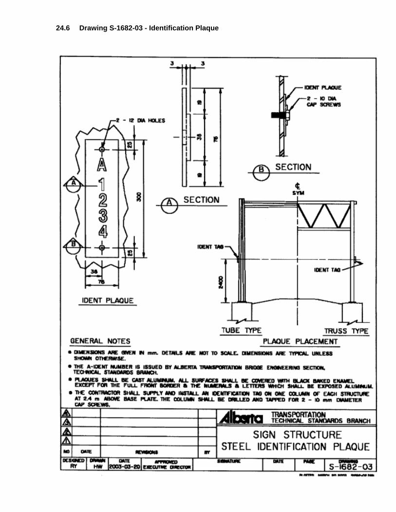
24.6 Drawing S-1682-03 - Identification Plaque
