seagate® nytro® 3731, 3531, 3331, and 3131 sas ssd · 2019-08-27 · seagate nytro 3731, 3531,...
TRANSCRIPT
Seagate® Nytro® 3731, 3531, 3331, and 3131 SAS SSD
Product Manual
100848978, Rev.CAugust 2019
Nytro 3731: Write Intensive (10 DWPD) Nytro 3531: Mixed Use (3 DWPD)
Capacity Standard Self-Encrypting FIPS 140-2 Standard Self-Encrypting FIPS 140-2
6400 GB -- -- -- XS6400LE70004 XS6400LE70014 --
3200 GB XS3200ME70004 XS3200ME70014 XS3200ME70024 XS3200LE70004 XS3200LE70014 XS3200LE70024
1600 GB XS1600ME70004 XS1600ME70014 XS1600ME70024 XS1600LE70004 XS1600LE70014 XS1600LE70024
800 GB XS800ME70004 XS800ME70014 -- XS800LE70004 XS800LE70014 XS800LE70024
400 GB XS400ME70004 XS400ME70014 -- -- -- --
Nytro 3331: Read Intensive (1 DWPD) Nytro 3131: Very Read Intensive (<1 DWPD)
Standard Self-Encrypting FIPS 140-2 Standard Self-Encrypting FIPS 140-2
15360 GB -- -- -- XS15360TE70004 XS15360TE70014 XS15360TE70024
7680 GB XS7680SE70004 XS7680SE70014 XS7680SE70024 XS7680TE70004 XS7680TE70014 --
3840 GB XS3840SE70004 XS3840SE70014 XS3840SE70024 XS3840TE70004 XS3840TE70014 --
1920 GB XS1920SE70004 XS1920SE70014 XS1920SE70024 -- -- --
960 GB XS960SE70004 XS960SE70014 XS960SE70024 -- -- --
© 2019, Seagate Technology LLC All rights reserved. Publication number: 100848978, Rev.C, August 2019
Seagate Technology reserves the right to make changes to the product(s) or information disclosed herein at any time without notice.
Revision History
Version and Date Description of Changes
Rev C, August 2019 Updated the following sections: Cover Section 2, Models Section 5.2.3, Throughput Performance Section 6.2, Endurance Section 4.2, Performance
Rev B, April 2019 Copy-edited throughout for readability.Updated content in the following sections: Section 3.1, Agency and Safety Certifications Section 4.6, Programmable drive capacity Section 5.2.3, Throughput Performance
Rev A, January 2019 First release of the document.
Seagate, Seagate Technology and the Spiral logo are registered trademarks of Seagate Technology LLC in the United States and/or other countries. Nytro and SeaTools are either trademarks or registered trademarks ofSeagate Technology LLC or one of its affiliated companies in the United States and/or other countries. All other trademarks or registered trademarks are the property of their respective owners.
No part of this publication may be reproduced in any form without written permission of Seagate Technology LLC. Call 877-PUB-TEK1(877-782-8351) to request permission.
The NVMe word mark and/or NVMExpress design mark are trademarks of NVMExpress, Inc. The PCIe word mark and/or PCIExpress design mark are registered trademarks and/or service marks of PCI-SIG.
When referring to drive capacity, one gigabyte, or GB, equals one billion bytes and one terabyte, or TB, equals one trillion bytes. Your computer’s operating system may use a different standard of measurement and reporta lower capacity. In addition, some of the listed capacity is used for formatting and other functions, and thus will not be available for data storage. Actual quantities will vary based on various factors, including file size, fileformat, features and application software. Actual data rates may vary depending on operating environment and other factors. The export or re-export of hardware or software containing encryption may be regulated bythe U.S. Department of Commerce, Bureau of Industry and Security (for more information, visit www.bis.doc.gov), and controlled for import and use outside of the U.S. Seagate reserves the right to change, without notice,product offerings or specifications.
Contents
Seagate Technology Support Services . . . . . . . . . . . . . . . . . . . . . . . . . . . . . . . . . . . . . . . . . . . . . . . . . . . . . . . . . . . . . . . . . . . . . . . . . . . . . . 6
1. Scope . . . . . . . . . . . . . . . . . . . . . . . . . . . . . . . . . . . . . . . . . . . . . . . . . . . . . . . . . . . . . . . . . . . . . . . . . . . . . . . . . . . . . . . . . . . . . . . . . . . . . . . . . . 7
2. Models . . . . . . . . . . . . . . . . . . . . . . . . . . . . . . . . . . . . . . . . . . . . . . . . . . . . . . . . . . . . . . . . . . . . . . . . . . . . . . . . . . . . . . . . . . . . . . . . . . . . . . . . . 8
3. Safety, Standards, and Compliance . . . . . . . . . . . . . . . . . . . . . . . . . . . . . . . . . . . . . . . . . . . . . . . . . . . . . . . . . . . . . . . . . . . . . . . . . . . . . . . 93.1 Agency and Safety Certifications . . . . . . . . . . . . . . . . . . . . . . . . . . . . . . . . . . . . . . . . . . . . . . . . . . . . . . . . . . . . . . . . . . . . . . . . . . . . . . . . . . . . . . . . . . . . . . . . . . . . 9
3.1.1 Regulatory Model . . . . . . . . . . . . . . . . . . . . . . . . . . . . . . . . . . . . . . . . . . . . . . . . . . . . . . . . . . . . . . . . . . . . . . . . . . . . . . . . . . . . . . . . . . . . . . . . . . . . . . . . . . . . 93.2 Reference documents . . . . . . . . . . . . . . . . . . . . . . . . . . . . . . . . . . . . . . . . . . . . . . . . . . . . . . . . . . . . . . . . . . . . . . . . . . . . . . . . . . . . . . . . . . . . . . . . . . . . . . . . . . . . . 10
4. General description . . . . . . . . . . . . . . . . . . . . . . . . . . . . . . . . . . . . . . . . . . . . . . . . . . . . . . . . . . . . . . . . . . . . . . . . . . . . . . . . . . . . . . . . . . . . 114.1 Standard features . . . . . . . . . . . . . . . . . . . . . . . . . . . . . . . . . . . . . . . . . . . . . . . . . . . . . . . . . . . . . . . . . . . . . . . . . . . . . . . . . . . . . . . . . . . . . . . . . . . . . . . . . . . . . . . . . . 114.2 Performance . . . . . . . . . . . . . . . . . . . . . . . . . . . . . . . . . . . . . . . . . . . . . . . . . . . . . . . . . . . . . . . . . . . . . . . . . . . . . . . . . . . . . . . . . . . . . . . . . . . . . . . . . . . . . . . . . . . . . . 124.3 Media description . . . . . . . . . . . . . . . . . . . . . . . . . . . . . . . . . . . . . . . . . . . . . . . . . . . . . . . . . . . . . . . . . . . . . . . . . . . . . . . . . . . . . . . . . . . . . . . . . . . . . . . . . . . . . . . . . 124.4 Warranty . . . . . . . . . . . . . . . . . . . . . . . . . . . . . . . . . . . . . . . . . . . . . . . . . . . . . . . . . . . . . . . . . . . . . . . . . . . . . . . . . . . . . . . . . . . . . . . . . . . . . . . . . . . . . . . . . . . . . . . . . . 124.5 Formatted capacities . . . . . . . . . . . . . . . . . . . . . . . . . . . . . . . . . . . . . . . . . . . . . . . . . . . . . . . . . . . . . . . . . . . . . . . . . . . . . . . . . . . . . . . . . . . . . . . . . . . . . . . . . . . . . . 124.6 Programmable drive capacity . . . . . . . . . . . . . . . . . . . . . . . . . . . . . . . . . . . . . . . . . . . . . . . . . . . . . . . . . . . . . . . . . . . . . . . . . . . . . . . . . . . . . . . . . . . . . . . . . . . . . . 144.7 Factory-installed options . . . . . . . . . . . . . . . . . . . . . . . . . . . . . . . . . . . . . . . . . . . . . . . . . . . . . . . . . . . . . . . . . . . . . . . . . . . . . . . . . . . . . . . . . . . . . . . . . . . . . . . . . . . 144.8 Logical Block Provisioning . . . . . . . . . . . . . . . . . . . . . . . . . . . . . . . . . . . . . . . . . . . . . . . . . . . . . . . . . . . . . . . . . . . . . . . . . . . . . . . . . . . . . . . . . . . . . . . . . . . . . . . . . 15
4.8.1 UNMAP . . . . . . . . . . . . . . . . . . . . . . . . . . . . . . . . . . . . . . . . . . . . . . . . . . . . . . . . . . . . . . . . . . . . . . . . . . . . . . . . . . . . . . . . . . . . . . . . . . . . . . . . . . . . . . . . . . . . . 154.8.2 FORMAT UNIT command . . . . . . . . . . . . . . . . . . . . . . . . . . . . . . . . . . . . . . . . . . . . . . . . . . . . . . . . . . . . . . . . . . . . . . . . . . . . . . . . . . . . . . . . . . . . . . . . . . . . 154.8.3 Protection Information (PI) and Security (SED) . . . . . . . . . . . . . . . . . . . . . . . . . . . . . . . . . . . . . . . . . . . . . . . . . . . . . . . . . . . . . . . . . . . . . . . . . . . . . . . . 15
5. Performance . . . . . . . . . . . . . . . . . . . . . . . . . . . . . . . . . . . . . . . . . . . . . . . . . . . . . . . . . . . . . . . . . . . . . . . . . . . . . . . . . . . . . . . . . . . . . . . . . . . 175.1 Internal drive characteristics . . . . . . . . . . . . . . . . . . . . . . . . . . . . . . . . . . . . . . . . . . . . . . . . . . . . . . . . . . . . . . . . . . . . . . . . . . . . . . . . . . . . . . . . . . . . . . . . . . . . . . . 175.2 Performance characteristics . . . . . . . . . . . . . . . . . . . . . . . . . . . . . . . . . . . . . . . . . . . . . . . . . . . . . . . . . . . . . . . . . . . . . . . . . . . . . . . . . . . . . . . . . . . . . . . . . . . . . . . . 18
5.2.1 Response time . . . . . . . . . . . . . . . . . . . . . . . . . . . . . . . . . . . . . . . . . . . . . . . . . . . . . . . . . . . . . . . . . . . . . . . . . . . . . . . . . . . . . . . . . . . . . . . . . . . . . . . . . . . . . . 185.2.2 FORMAT UNIT command execution time for 512-byte LBA's (minutes) . . . . . . . . . . . . . . . . . . . . . . . . . . . . . . . . . . . . . . . . . . . . . . . . . . . . . . . . 185.2.3 Throughput Performance . . . . . . . . . . . . . . . . . . . . . . . . . . . . . . . . . . . . . . . . . . . . . . . . . . . . . . . . . . . . . . . . . . . . . . . . . . . . . . . . . . . . . . . . . . . . . . . . . . . 19
5.3 Start/stop time . . . . . . . . . . . . . . . . . . . . . . . . . . . . . . . . . . . . . . . . . . . . . . . . . . . . . . . . . . . . . . . . . . . . . . . . . . . . . . . . . . . . . . . . . . . . . . . . . . . . . . . . . . . . . . . . . . . . 215.3.1 Caching write data . . . . . . . . . . . . . . . . . . . . . . . . . . . . . . . . . . . . . . . . . . . . . . . . . . . . . . . . . . . . . . . . . . . . . . . . . . . . . . . . . . . . . . . . . . . . . . . . . . . . . . . . . . 215.3.2 Prefetch operation . . . . . . . . . . . . . . . . . . . . . . . . . . . . . . . . . . . . . . . . . . . . . . . . . . . . . . . . . . . . . . . . . . . . . . . . . . . . . . . . . . . . . . . . . . . . . . . . . . . . . . . . . . 22
6. Reliability specifications . . . . . . . . . . . . . . . . . . . . . . . . . . . . . . . . . . . . . . . . . . . . . . . . . . . . . . . . . . . . . . . . . . . . . . . . . . . . . . . . . . . . . . . . 236.1 Read error rates . . . . . . . . . . . . . . . . . . . . . . . . . . . . . . . . . . . . . . . . . . . . . . . . . . . . . . . . . . . . . . . . . . . . . . . . . . . . . . . . . . . . . . . . . . . . . . . . . . . . . . . . . . . . . . . . . . . . 236.2 Endurance . . . . . . . . . . . . . . . . . . . . . . . . . . . . . . . . . . . . . . . . . . . . . . . . . . . . . . . . . . . . . . . . . . . . . . . . . . . . . . . . . . . . . . . . . . . . . . . . . . . . . . . . . . . . . . . . . . . . . . . . . 246.3 Error rates . . . . . . . . . . . . . . . . . . . . . . . . . . . . . . . . . . . . . . . . . . . . . . . . . . . . . . . . . . . . . . . . . . . . . . . . . . . . . . . . . . . . . . . . . . . . . . . . . . . . . . . . . . . . . . . . . . . . . . . . . 25
6.3.1 Unrecoverable Errors . . . . . . . . . . . . . . . . . . . . . . . . . . . . . . . . . . . . . . . . . . . . . . . . . . . . . . . . . . . . . . . . . . . . . . . . . . . . . . . . . . . . . . . . . . . . . . . . . . . . . . . . 256.3.2 Interface errors . . . . . . . . . . . . . . . . . . . . . . . . . . . . . . . . . . . . . . . . . . . . . . . . . . . . . . . . . . . . . . . . . . . . . . . . . . . . . . . . . . . . . . . . . . . . . . . . . . . . . . . . . . . . . . 25
6.4 Endurance management . . . . . . . . . . . . . . . . . . . . . . . . . . . . . . . . . . . . . . . . . . . . . . . . . . . . . . . . . . . . . . . . . . . . . . . . . . . . . . . . . . . . . . . . . . . . . . . . . . . . . . . . . . . 256.4.1 Wear leveling . . . . . . . . . . . . . . . . . . . . . . . . . . . . . . . . . . . . . . . . . . . . . . . . . . . . . . . . . . . . . . . . . . . . . . . . . . . . . . . . . . . . . . . . . . . . . . . . . . . . . . . . . . . . . . . 256.4.2 Garbage collection . . . . . . . . . . . . . . . . . . . . . . . . . . . . . . . . . . . . . . . . . . . . . . . . . . . . . . . . . . . . . . . . . . . . . . . . . . . . . . . . . . . . . . . . . . . . . . . . . . . . . . . . . . 256.4.3 Write amplification . . . . . . . . . . . . . . . . . . . . . . . . . . . . . . . . . . . . . . . . . . . . . . . . . . . . . . . . . . . . . . . . . . . . . . . . . . . . . . . . . . . . . . . . . . . . . . . . . . . . . . . . . . 266.4.4 UNMAP . . . . . . . . . . . . . . . . . . . . . . . . . . . . . . . . . . . . . . . . . . . . . . . . . . . . . . . . . . . . . . . . . . . . . . . . . . . . . . . . . . . . . . . . . . . . . . . . . . . . . . . . . . . . . . . . . . . . . 266.4.5 Data retention . . . . . . . . . . . . . . . . . . . . . . . . . . . . . . . . . . . . . . . . . . . . . . . . . . . . . . . . . . . . . . . . . . . . . . . . . . . . . . . . . . . . . . . . . . . . . . . . . . . . . . . . . . . . . . 266.4.6 Write stream tagging . . . . . . . . . . . . . . . . . . . . . . . . . . . . . . . . . . . . . . . . . . . . . . . . . . . . . . . . . . . . . . . . . . . . . . . . . . . . . . . . . . . . . . . . . . . . . . . . . . . . . . . . 266.4.7 SSD percentage used endurance indicator . . . . . . . . . . . . . . . . . . . . . . . . . . . . . . . . . . . . . . . . . . . . . . . . . . . . . . . . . . . . . . . . . . . . . . . . . . . . . . . . . . . 26
Seagate Nytro 3731, 3531, 3331, 3131 SAS SSD Product Manual, Rev. C 3
Contents
6.5 Reliability and service . . . . . . . . . . . . . . . . . . . . . . . . . . . . . . . . . . . . . . . . . . . . . . . . . . . . . . . . . . . . . . . . . . . . . . . . . . . . . . . . . . . . . . . . . . . . . . . . . . . . . . . . . . . . . . 266.5.1 Annualized Failure Rate (AFR) and Mean Time Between Failure (MTBF) . . . . . . . . . . . . . . . . . . . . . . . . . . . . . . . . . . . . . . . . . . . . . . . . . . . . . . . . 276.5.2 Preventive maintenance . . . . . . . . . . . . . . . . . . . . . . . . . . . . . . . . . . . . . . . . . . . . . . . . . . . . . . . . . . . . . . . . . . . . . . . . . . . . . . . . . . . . . . . . . . . . . . . . . . . . . 276.5.3 Hot plugging the drive . . . . . . . . . . . . . . . . . . . . . . . . . . . . . . . . . . . . . . . . . . . . . . . . . . . . . . . . . . . . . . . . . . . . . . . . . . . . . . . . . . . . . . . . . . . . . . . . . . . . . . 276.5.4 S.M.A.R.T. . . . . . . . . . . . . . . . . . . . . . . . . . . . . . . . . . . . . . . . . . . . . . . . . . . . . . . . . . . . . . . . . . . . . . . . . . . . . . . . . . . . . . . . . . . . . . . . . . . . . . . . . . . . . . . . . . . . 27
6.5.4.1 Controlling S.M.A.R.T. . . . . . . . . . . . . . . . . . . . . . . . . . . . . . . . . . . . . . . . . . . . . . . . . . . . . . . . . . . . . . . . . . . . . . . . . . . . . . . . . . . . . . . . . . . . . . . . . . 286.5.4.2 Performance impact . . . . . . . . . . . . . . . . . . . . . . . . . . . . . . . . . . . . . . . . . . . . . . . . . . . . . . . . . . . . . . . . . . . . . . . . . . . . . . . . . . . . . . . . . . . . . . . . . . 286.5.4.3 Reporting control . . . . . . . . . . . . . . . . . . . . . . . . . . . . . . . . . . . . . . . . . . . . . . . . . . . . . . . . . . . . . . . . . . . . . . . . . . . . . . . . . . . . . . . . . . . . . . . . . . . . . 286.5.4.4 Determining rate . . . . . . . . . . . . . . . . . . . . . . . . . . . . . . . . . . . . . . . . . . . . . . . . . . . . . . . . . . . . . . . . . . . . . . . . . . . . . . . . . . . . . . . . . . . . . . . . . . . . . 286.5.4.5 Predictive failures . . . . . . . . . . . . . . . . . . . . . . . . . . . . . . . . . . . . . . . . . . . . . . . . . . . . . . . . . . . . . . . . . . . . . . . . . . . . . . . . . . . . . . . . . . . . . . . . . . . . . 28
6.5.5 Thermal monitor . . . . . . . . . . . . . . . . . . . . . . . . . . . . . . . . . . . . . . . . . . . . . . . . . . . . . . . . . . . . . . . . . . . . . . . . . . . . . . . . . . . . . . . . . . . . . . . . . . . . . . . . . . . . 296.5.6 Drive Self Test (DST) . . . . . . . . . . . . . . . . . . . . . . . . . . . . . . . . . . . . . . . . . . . . . . . . . . . . . . . . . . . . . . . . . . . . . . . . . . . . . . . . . . . . . . . . . . . . . . . . . . . . . . . . . 29
6.5.6.1 DST failure definition . . . . . . . . . . . . . . . . . . . . . . . . . . . . . . . . . . . . . . . . . . . . . . . . . . . . . . . . . . . . . . . . . . . . . . . . . . . . . . . . . . . . . . . . . . . . . . . . . 296.5.6.2 Implementation . . . . . . . . . . . . . . . . . . . . . . . . . . . . . . . . . . . . . . . . . . . . . . . . . . . . . . . . . . . . . . . . . . . . . . . . . . . . . . . . . . . . . . . . . . . . . . . . . . . . . . 296.5.6.3 State of the drive prior to testing . . . . . . . . . . . . . . . . . . . . . . . . . . . . . . . . . . . . . . . . . . . . . . . . . . . . . . . . . . . . . . . . . . . . . . . . . . . . . . . . . . . . . . 296.5.6.4 Invoking DST . . . . . . . . . . . . . . . . . . . . . . . . . . . . . . . . . . . . . . . . . . . . . . . . . . . . . . . . . . . . . . . . . . . . . . . . . . . . . . . . . . . . . . . . . . . . . . . . . . . . . . . . . 306.5.6.5 Log page entries . . . . . . . . . . . . . . . . . . . . . . . . . . . . . . . . . . . . . . . . . . . . . . . . . . . . . . . . . . . . . . . . . . . . . . . . . . . . . . . . . . . . . . . . . . . . . . . . . . . . . . 306.5.6.6 Abort . . . . . . . . . . . . . . . . . . . . . . . . . . . . . . . . . . . . . . . . . . . . . . . . . . . . . . . . . . . . . . . . . . . . . . . . . . . . . . . . . . . . . . . . . . . . . . . . . . . . . . . . . . . . . . . . . 30
6.5.7 Product warranty . . . . . . . . . . . . . . . . . . . . . . . . . . . . . . . . . . . . . . . . . . . . . . . . . . . . . . . . . . . . . . . . . . . . . . . . . . . . . . . . . . . . . . . . . . . . . . . . . . . . . . . . . . . 306.5.8 Shipping . . . . . . . . . . . . . . . . . . . . . . . . . . . . . . . . . . . . . . . . . . . . . . . . . . . . . . . . . . . . . . . . . . . . . . . . . . . . . . . . . . . . . . . . . . . . . . . . . . . . . . . . . . . . . . . . . . . . 31
6.5.8.1 Product repair and return information . . . . . . . . . . . . . . . . . . . . . . . . . . . . . . . . . . . . . . . . . . . . . . . . . . . . . . . . . . . . . . . . . . . . . . . . . . . . . . . . . 316.5.8.2 Storage . . . . . . . . . . . . . . . . . . . . . . . . . . . . . . . . . . . . . . . . . . . . . . . . . . . . . . . . . . . . . . . . . . . . . . . . . . . . . . . . . . . . . . . . . . . . . . . . . . . . . . . . . . . . . . 31
7. Physical and electrical specifications . . . . . . . . . . . . . . . . . . . . . . . . . . . . . . . . . . . . . . . . . . . . . . . . . . . . . . . . . . . . . . . . . . . . . . . . . . . . 327.1 Power specifications . . . . . . . . . . . . . . . . . . . . . . . . . . . . . . . . . . . . . . . . . . . . . . . . . . . . . . . . . . . . . . . . . . . . . . . . . . . . . . . . . . . . . . . . . . . . . . . . . . . . . . . . . . . . . . . 32
7.1.1 Conducted noise immunity . . . . . . . . . . . . . . . . . . . . . . . . . . . . . . . . . . . . . . . . . . . . . . . . . . . . . . . . . . . . . . . . . . . . . . . . . . . . . . . . . . . . . . . . . . . . . . . . . . 337.1.2 Power sequencing . . . . . . . . . . . . . . . . . . . . . . . . . . . . . . . . . . . . . . . . . . . . . . . . . . . . . . . . . . . . . . . . . . . . . . . . . . . . . . . . . . . . . . . . . . . . . . . . . . . . . . . . . . 33
7.2 Power consumption . . . . . . . . . . . . . . . . . . . . . . . . . . . . . . . . . . . . . . . . . . . . . . . . . . . . . . . . . . . . . . . . . . . . . . . . . . . . . . . . . . . . . . . . . . . . . . . . . . . . . . . . . . . . . . . 337.2.1 Direct Current Consumption by Voltage Rail . . . . . . . . . . . . . . . . . . . . . . . . . . . . . . . . . . . . . . . . . . . . . . . . . . . . . . . . . . . . . . . . . . . . . . . . . . . . . . . . . 33
7.2.1.1 Power Consumption . . . . . . . . . . . . . . . . . . . . . . . . . . . . . . . . . . . . . . . . . . . . . . . . . . . . . . . . . . . . . . . . . . . . . . . . . . . . . . . . . . . . . . . . . . . . . . . . . . 347.2.2 Current profiles . . . . . . . . . . . . . . . . . . . . . . . . . . . . . . . . . . . . . . . . . . . . . . . . . . . . . . . . . . . . . . . . . . . . . . . . . . . . . . . . . . . . . . . . . . . . . . . . . . . . . . . . . . . . . 49
7.3 Environmental limits . . . . . . . . . . . . . . . . . . . . . . . . . . . . . . . . . . . . . . . . . . . . . . . . . . . . . . . . . . . . . . . . . . . . . . . . . . . . . . . . . . . . . . . . . . . . . . . . . . . . . . . . . . . . . . . 517.3.1 Temperature . . . . . . . . . . . . . . . . . . . . . . . . . . . . . . . . . . . . . . . . . . . . . . . . . . . . . . . . . . . . . . . . . . . . . . . . . . . . . . . . . . . . . . . . . . . . . . . . . . . . . . . . . . . . . . . . 51
7.3.1.1 Operating . . . . . . . . . . . . . . . . . . . . . . . . . . . . . . . . . . . . . . . . . . . . . . . . . . . . . . . . . . . . . . . . . . . . . . . . . . . . . . . . . . . . . . . . . . . . . . . . . . . . . . . . . . . . 517.3.1.2 Non-operating . . . . . . . . . . . . . . . . . . . . . . . . . . . . . . . . . . . . . . . . . . . . . . . . . . . . . . . . . . . . . . . . . . . . . . . . . . . . . . . . . . . . . . . . . . . . . . . . . . . . . . . 51
7.3.2 Relative humidity . . . . . . . . . . . . . . . . . . . . . . . . . . . . . . . . . . . . . . . . . . . . . . . . . . . . . . . . . . . . . . . . . . . . . . . . . . . . . . . . . . . . . . . . . . . . . . . . . . . . . . . . . . . 517.3.3 Effective altitude (sea level) . . . . . . . . . . . . . . . . . . . . . . . . . . . . . . . . . . . . . . . . . . . . . . . . . . . . . . . . . . . . . . . . . . . . . . . . . . . . . . . . . . . . . . . . . . . . . . . . . . 527.3.4 Shock and vibration . . . . . . . . . . . . . . . . . . . . . . . . . . . . . . . . . . . . . . . . . . . . . . . . . . . . . . . . . . . . . . . . . . . . . . . . . . . . . . . . . . . . . . . . . . . . . . . . . . . . . . . . . 52
7.3.4.1 Shock . . . . . . . . . . . . . . . . . . . . . . . . . . . . . . . . . . . . . . . . . . . . . . . . . . . . . . . . . . . . . . . . . . . . . . . . . . . . . . . . . . . . . . . . . . . . . . . . . . . . . . . . . . . . . . . . 527.3.4.2 Vibration . . . . . . . . . . . . . . . . . . . . . . . . . . . . . . . . . . . . . . . . . . . . . . . . . . . . . . . . . . . . . . . . . . . . . . . . . . . . . . . . . . . . . . . . . . . . . . . . . . . . . . . . . . . . . 53
7.3.5 Air cleanliness . . . . . . . . . . . . . . . . . . . . . . . . . . . . . . . . . . . . . . . . . . . . . . . . . . . . . . . . . . . . . . . . . . . . . . . . . . . . . . . . . . . . . . . . . . . . . . . . . . . . . . . . . . . . . . . 537.3.6 Corrosive environment . . . . . . . . . . . . . . . . . . . . . . . . . . . . . . . . . . . . . . . . . . . . . . . . . . . . . . . . . . . . . . . . . . . . . . . . . . . . . . . . . . . . . . . . . . . . . . . . . . . . . . 53
7.4 Mechanical specifications . . . . . . . . . . . . . . . . . . . . . . . . . . . . . . . . . . . . . . . . . . . . . . . . . . . . . . . . . . . . . . . . . . . . . . . . . . . . . . . . . . . . . . . . . . . . . . . . . . . . . . . . . . 547.4.1 Weight . . . . . . . . . . . . . . . . . . . . . . . . . . . . . . . . . . . . . . . . . . . . . . . . . . . . . . . . . . . . . . . . . . . . . . . . . . . . . . . . . . . . . . . . . . . . . . . . . . . . . . . . . . . . . . . . . . . . . 56
8. About FIPS . . . . . . . . . . . . . . . . . . . . . . . . . . . . . . . . . . . . . . . . . . . . . . . . . . . . . . . . . . . . . . . . . . . . . . . . . . . . . . . . . . . . . . . . . . . . . . . . . . . . 578.1 Purpose . . . . . . . . . . . . . . . . . . . . . . . . . . . . . . . . . . . . . . . . . . . . . . . . . . . . . . . . . . . . . . . . . . . . . . . . . . . . . . . . . . . . . . . . . . . . . . . . . . . . . . . . . . . . . . . . . . . . . . . . . . . 578.2 Validation Program . . . . . . . . . . . . . . . . . . . . . . . . . . . . . . . . . . . . . . . . . . . . . . . . . . . . . . . . . . . . . . . . . . . . . . . . . . . . . . . . . . . . . . . . . . . . . . . . . . . . . . . . . . . . . . . . 578.3 Seagate Enterprise SED . . . . . . . . . . . . . . . . . . . . . . . . . . . . . . . . . . . . . . . . . . . . . . . . . . . . . . . . . . . . . . . . . . . . . . . . . . . . . . . . . . . . . . . . . . . . . . . . . . . . . . . . . . . . 578.4 Security Level 2 . . . . . . . . . . . . . . . . . . . . . . . . . . . . . . . . . . . . . . . . . . . . . . . . . . . . . . . . . . . . . . . . . . . . . . . . . . . . . . . . . . . . . . . . . . . . . . . . . . . . . . . . . . . . . . . . . . . . 58
9. About self-encrypting drives . . . . . . . . . . . . . . . . . . . . . . . . . . . . . . . . . . . . . . . . . . . . . . . . . . . . . . . . . . . . . . . . . . . . . . . . . . . . . . . . . . . . 599.1 Data encryption . . . . . . . . . . . . . . . . . . . . . . . . . . . . . . . . . . . . . . . . . . . . . . . . . . . . . . . . . . . . . . . . . . . . . . . . . . . . . . . . . . . . . . . . . . . . . . . . . . . . . . . . . . . . . . . . . . . 599.2 Controlled access . . . . . . . . . . . . . . . . . . . . . . . . . . . . . . . . . . . . . . . . . . . . . . . . . . . . . . . . . . . . . . . . . . . . . . . . . . . . . . . . . . . . . . . . . . . . . . . . . . . . . . . . . . . . . . . . . . 59
9.2.1 Admin SP . . . . . . . . . . . . . . . . . . . . . . . . . . . . . . . . . . . . . . . . . . . . . . . . . . . . . . . . . . . . . . . . . . . . . . . . . . . . . . . . . . . . . . . . . . . . . . . . . . . . . . . . . . . . . . . . . . . 599.2.2 Locking SP . . . . . . . . . . . . . . . . . . . . . . . . . . . . . . . . . . . . . . . . . . . . . . . . . . . . . . . . . . . . . . . . . . . . . . . . . . . . . . . . . . . . . . . . . . . . . . . . . . . . . . . . . . . . . . . . . . 599.2.3 Default password . . . . . . . . . . . . . . . . . . . . . . . . . . . . . . . . . . . . . . . . . . . . . . . . . . . . . . . . . . . . . . . . . . . . . . . . . . . . . . . . . . . . . . . . . . . . . . . . . . . . . . . . . . . 60
9.3 Random number generator (RNG) . . . . . . . . . . . . . . . . . . . . . . . . . . . . . . . . . . . . . . . . . . . . . . . . . . . . . . . . . . . . . . . . . . . . . . . . . . . . . . . . . . . . . . . . . . . . . . . . . . 60
Seagate Nytro 3731, 3531, 3331, 3131 SAS SSD Product Manual, Rev. C 4
Contents
9.4 Drive locking . . . . . . . . . . . . . . . . . . . . . . . . . . . . . . . . . . . . . . . . . . . . . . . . . . . . . . . . . . . . . . . . . . . . . . . . . . . . . . . . . . . . . . . . . . . . . . . . . . . . . . . . . . . . . . . . . . . . . . 609.5 Data bands . . . . . . . . . . . . . . . . . . . . . . . . . . . . . . . . . . . . . . . . . . . . . . . . . . . . . . . . . . . . . . . . . . . . . . . . . . . . . . . . . . . . . . . . . . . . . . . . . . . . . . . . . . . . . . . . . . . . . . . . 609.6 Cryptographic erase . . . . . . . . . . . . . . . . . . . . . . . . . . . . . . . . . . . . . . . . . . . . . . . . . . . . . . . . . . . . . . . . . . . . . . . . . . . . . . . . . . . . . . . . . . . . . . . . . . . . . . . . . . . . . . . 619.7 Authenticated firmware download . . . . . . . . . . . . . . . . . . . . . . . . . . . . . . . . . . . . . . . . . . . . . . . . . . . . . . . . . . . . . . . . . . . . . . . . . . . . . . . . . . . . . . . . . . . . . . . . . 619.8 Power requirements . . . . . . . . . . . . . . . . . . . . . . . . . . . . . . . . . . . . . . . . . . . . . . . . . . . . . . . . . . . . . . . . . . . . . . . . . . . . . . . . . . . . . . . . . . . . . . . . . . . . . . . . . . . . . . . 619.9 Supported commands . . . . . . . . . . . . . . . . . . . . . . . . . . . . . . . . . . . . . . . . . . . . . . . . . . . . . . . . . . . . . . . . . . . . . . . . . . . . . . . . . . . . . . . . . . . . . . . . . . . . . . . . . . . . . 629.10 Sanitize - Cryptographic Erase . . . . . . . . . . . . . . . . . . . . . . . . . . . . . . . . . . . . . . . . . . . . . . . . . . . . . . . . . . . . . . . . . . . . . . . . . . . . . . . . . . . . . . . . . . . . . . . . . . . . 629.11 RevertSP . . . . . . . . . . . . . . . . . . . . . . . . . . . . . . . . . . . . . . . . . . . . . . . . . . . . . . . . . . . . . . . . . . . . . . . . . . . . . . . . . . . . . . . . . . . . . . . . . . . . . . . . . . . . . . . . . . . . . . . . . 62
10. Defect and error management . . . . . . . . . . . . . . . . . . . . . . . . . . . . . . . . . . . . . . . . . . . . . . . . . . . . . . . . . . . . . . . . . . . . . . . . . . . . . . . . . 6310.1 Drive internal defects/errors . . . . . . . . . . . . . . . . . . . . . . . . . . . . . . . . . . . . . . . . . . . . . . . . . . . . . . . . . . . . . . . . . . . . . . . . . . . . . . . . . . . . . . . . . . . . . . . . . . . . . . 6310.2 Drive error recovery procedures . . . . . . . . . . . . . . . . . . . . . . . . . . . . . . . . . . . . . . . . . . . . . . . . . . . . . . . . . . . . . . . . . . . . . . . . . . . . . . . . . . . . . . . . . . . . . . . . . . 6410.3 SAS system errors . . . . . . . . . . . . . . . . . . . . . . . . . . . . . . . . . . . . . . . . . . . . . . . . . . . . . . . . . . . . . . . . . . . . . . . . . . . . . . . . . . . . . . . . . . . . . . . . . . . . . . . . . . . . . . . . 6410.4 Auto-Reallocation . . . . . . . . . . . . . . . . . . . . . . . . . . . . . . . . . . . . . . . . . . . . . . . . . . . . . . . . . . . . . . . . . . . . . . . . . . . . . . . . . . . . . . . . . . . . . . . . . . . . . . . . . . . . . . . . 6410.5 Protection Information (PI) . . . . . . . . . . . . . . . . . . . . . . . . . . . . . . . . . . . . . . . . . . . . . . . . . . . . . . . . . . . . . . . . . . . . . . . . . . . . . . . . . . . . . . . . . . . . . . . . . . . . . . . . 64
10.5.1 Levels of PI . . . . . . . . . . . . . . . . . . . . . . . . . . . . . . . . . . . . . . . . . . . . . . . . . . . . . . . . . . . . . . . . . . . . . . . . . . . . . . . . . . . . . . . . . . . . . . . . . . . . . . . . . . . . . . . . 6510.5.2 Setting and determining the current Type Level . . . . . . . . . . . . . . . . . . . . . . . . . . . . . . . . . . . . . . . . . . . . . . . . . . . . . . . . . . . . . . . . . . . . . . . . . . . . 6510.5.3 Identifying a Protection Information drive . . . . . . . . . . . . . . . . . . . . . . . . . . . . . . . . . . . . . . . . . . . . . . . . . . . . . . . . . . . . . . . . . . . . . . . . . . . . . . . . . . 65
11. Installation . . . . . . . . . . . . . . . . . . . . . . . . . . . . . . . . . . . . . . . . . . . . . . . . . . . . . . . . . . . . . . . . . . . . . . . . . . . . . . . . . . . . . . . . . . . . . . . . . . . 6611.1 Drive orientation . . . . . . . . . . . . . . . . . . . . . . . . . . . . . . . . . . . . . . . . . . . . . . . . . . . . . . . . . . . . . . . . . . . . . . . . . . . . . . . . . . . . . . . . . . . . . . . . . . . . . . . . . . . . . . . . . 6611.2 Cooling . . . . . . . . . . . . . . . . . . . . . . . . . . . . . . . . . . . . . . . . . . . . . . . . . . . . . . . . . . . . . . . . . . . . . . . . . . . . . . . . . . . . . . . . . . . . . . . . . . . . . . . . . . . . . . . . . . . . . . . . . . 6611.3 Drive mounting . . . . . . . . . . . . . . . . . . . . . . . . . . . . . . . . . . . . . . . . . . . . . . . . . . . . . . . . . . . . . . . . . . . . . . . . . . . . . . . . . . . . . . . . . . . . . . . . . . . . . . . . . . . . . . . . . . 6811.4 Grounding . . . . . . . . . . . . . . . . . . . . . . . . . . . . . . . . . . . . . . . . . . . . . . . . . . . . . . . . . . . . . . . . . . . . . . . . . . . . . . . . . . . . . . . . . . . . . . . . . . . . . . . . . . . . . . . . . . . . . . . 68
12. Interface requirements . . . . . . . . . . . . . . . . . . . . . . . . . . . . . . . . . . . . . . . . . . . . . . . . . . . . . . . . . . . . . . . . . . . . . . . . . . . . . . . . . . . . . . . . 6912.1 SAS features . . . . . . . . . . . . . . . . . . . . . . . . . . . . . . . . . . . . . . . . . . . . . . . . . . . . . . . . . . . . . . . . . . . . . . . . . . . . . . . . . . . . . . . . . . . . . . . . . . . . . . . . . . . . . . . . . . . . . . 69
12.1.1 Task management functions . . . . . . . . . . . . . . . . . . . . . . . . . . . . . . . . . . . . . . . . . . . . . . . . . . . . . . . . . . . . . . . . . . . . . . . . . . . . . . . . . . . . . . . . . . . . . . . 6912.1.2 Task management responses . . . . . . . . . . . . . . . . . . . . . . . . . . . . . . . . . . . . . . . . . . . . . . . . . . . . . . . . . . . . . . . . . . . . . . . . . . . . . . . . . . . . . . . . . . . . . . . 69
12.2 Dual port support . . . . . . . . . . . . . . . . . . . . . . . . . . . . . . . . . . . . . . . . . . . . . . . . . . . . . . . . . . . . . . . . . . . . . . . . . . . . . . . . . . . . . . . . . . . . . . . . . . . . . . . . . . . . . . . . 7012.3 SCSI commands supported . . . . . . . . . . . . . . . . . . . . . . . . . . . . . . . . . . . . . . . . . . . . . . . . . . . . . . . . . . . . . . . . . . . . . . . . . . . . . . . . . . . . . . . . . . . . . . . . . . . . . . . 70
12.3.1 INQUIRY data . . . . . . . . . . . . . . . . . . . . . . . . . . . . . . . . . . . . . . . . . . . . . . . . . . . . . . . . . . . . . . . . . . . . . . . . . . . . . . . . . . . . . . . . . . . . . . . . . . . . . . . . . . . . . . 7612.3.2 MODE SENSE data . . . . . . . . . . . . . . . . . . . . . . . . . . . . . . . . . . . . . . . . . . . . . . . . . . . . . . . . . . . . . . . . . . . . . . . . . . . . . . . . . . . . . . . . . . . . . . . . . . . . . . . . . 78
12.4 Miscellaneous operating features and conditions . . . . . . . . . . . . . . . . . . . . . . . . . . . . . . . . . . . . . . . . . . . . . . . . . . . . . . . . . . . . . . . . . . . . . . . . . . . . . . . . . . 8012.4.1 SAS physical interface . . . . . . . . . . . . . . . . . . . . . . . . . . . . . . . . . . . . . . . . . . . . . . . . . . . . . . . . . . . . . . . . . . . . . . . . . . . . . . . . . . . . . . . . . . . . . . . . . . . . . . 8112.4.2 Physical characteristics . . . . . . . . . . . . . . . . . . . . . . . . . . . . . . . . . . . . . . . . . . . . . . . . . . . . . . . . . . . . . . . . . . . . . . . . . . . . . . . . . . . . . . . . . . . . . . . . . . . . . 8412.4.3 Connector requirements . . . . . . . . . . . . . . . . . . . . . . . . . . . . . . . . . . . . . . . . . . . . . . . . . . . . . . . . . . . . . . . . . . . . . . . . . . . . . . . . . . . . . . . . . . . . . . . . . . . 8412.4.4 Electrical description . . . . . . . . . . . . . . . . . . . . . . . . . . . . . . . . . . . . . . . . . . . . . . . . . . . . . . . . . . . . . . . . . . . . . . . . . . . . . . . . . . . . . . . . . . . . . . . . . . . . . . . 8412.4.5 Pin descriptions . . . . . . . . . . . . . . . . . . . . . . . . . . . . . . . . . . . . . . . . . . . . . . . . . . . . . . . . . . . . . . . . . . . . . . . . . . . . . . . . . . . . . . . . . . . . . . . . . . . . . . . . . . . . 8512.4.6 SAS transmitters and receivers . . . . . . . . . . . . . . . . . . . . . . . . . . . . . . . . . . . . . . . . . . . . . . . . . . . . . . . . . . . . . . . . . . . . . . . . . . . . . . . . . . . . . . . . . . . . . 8612.4.7 Power . . . . . . . . . . . . . . . . . . . . . . . . . . . . . . . . . . . . . . . . . . . . . . . . . . . . . . . . . . . . . . . . . . . . . . . . . . . . . . . . . . . . . . . . . . . . . . . . . . . . . . . . . . . . . . . . . . . . . 86
12.5 Signal characteristics . . . . . . . . . . . . . . . . . . . . . . . . . . . . . . . . . . . . . . . . . . . . . . . . . . . . . . . . . . . . . . . . . . . . . . . . . . . . . . . . . . . . . . . . . . . . . . . . . . . . . . . . . . . . . 8712.5.1 Ready LED Out . . . . . . . . . . . . . . . . . . . . . . . . . . . . . . . . . . . . . . . . . . . . . . . . . . . . . . . . . . . . . . . . . . . . . . . . . . . . . . . . . . . . . . . . . . . . . . . . . . . . . . . . . . . . . 8712.5.2 Differential signals . . . . . . . . . . . . . . . . . . . . . . . . . . . . . . . . . . . . . . . . . . . . . . . . . . . . . . . . . . . . . . . . . . . . . . . . . . . . . . . . . . . . . . . . . . . . . . . . . . . . . . . . . 88
12.6 SAS-3 Specification compliance . . . . . . . . . . . . . . . . . . . . . . . . . . . . . . . . . . . . . . . . . . . . . . . . . . . . . . . . . . . . . . . . . . . . . . . . . . . . . . . . . . . . . . . . . . . . . . . . . . . 8912.7 Additional information . . . . . . . . . . . . . . . . . . . . . . . . . . . . . . . . . . . . . . . . . . . . . . . . . . . . . . . . . . . . . . . . . . . . . . . . . . . . . . . . . . . . . . . . . . . . . . . . . . . . . . . . . . . 89
Seagate Nytro 3731, 3531, 3331, 3131 SAS SSD Product Manual, Rev. C 5
Seagate Nytro 3731, 3531, 3331, 3131 SAS SSD Product Manual, Rev. C 6
Seagate Technology Support Services
For Internal SSD Support, visit: https://www.seagate.com/support/products/
For Firmware Download and Tools Download for Secure Erase, visit: https://www.seagate.com/support/downloads/
For information regarding online support and services, visit: http://www.seagate.com/contacts/
For information regarding Warranty Support, visit: http://www.seagate.com/support/warranty-and-replacements/
For information regarding data recovery services, visit: http://www.seagate.com/services-software/seagate-recovery-services/recover/
For Seagate OEM and Distribution partner and Seagate reseller portal, visit: http://www.seagate.com/partners
www.seagate.com
1. Scope
This manual describes Seagate Nytro® 3000 SAS (Serial Attached SCSI) Solid State Drives (SSD).
Seagate Nytro® 3000 SSDs support the SAS Protocol specifications described in this manual. The SAS Interface Manual (part number 100293071) describes the SAS characteristics of this and other Seagate SAS drives. The Self- Encrypting Drive Reference Manual, part number 100515636, describes the interface, general operation, and security features available on Self-Encrypting Drive (SED) models.
Product data in this manual refers only to the model numbers listed in this manual. The data in this manual may predict future generation specifications or requirements. If you are designing a system using one of the models listed or future generation products and you need further assistance, please contact the Field Applications Engineer (FAE) or our global support services group.
Unless otherwise stated, the information in this manual applies to standard Secure Download and Diagnostic (SD&D) and SED models.
Seagate Nytro 3731, 3531, 3331, 3131 SAS SSD Product Manual, Rev. C 7
www.seagate.com
2. Models
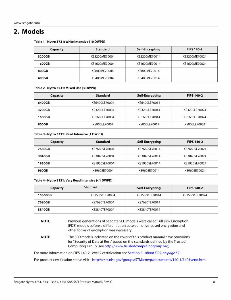
NOTE Previous generations of Seagate SED models were called Full Disk Encryption (FDE) models before a differentiation between drive-based encryption and other forms of encryption was necessary.
NOTE The SED models indicated on the cover of this product manual have provisions for "Security of Data at Rest" based on the standards defined by the Trusted Computing Group (see http://www.trustedcomputinggroup.org).
For more information on FIPS 140-2 Level 2 certification see Section 8. About FIPS, on page 57.
For product certification status visit - http://csrc.nist.gov/groups/STM/cmvp/documents/140-1/1401vend.htm.
Table 1 - Nytro 3731: Write Intensive (10 DWPD)
Capacity Standard Self-Encrypting FIPS 140-2
3200GB XS3200ME70004 XS3200ME70014 XS3200ME70024
1600GB XS1600ME70004 XS1600ME70014 XS1600ME70024
800GB XS800ME70004 XS800ME70014
400GB XS400ME70004 XS400ME70014
Table 2 - Nytro 3531: Mixed Use (3 DWPD)
Capacity Standard Self-Encrypting FIPS 140-2
6400GB XS6400LE70004 XS6400LE70014
3200GB XS3200LE70004 XS3200LE70014 XS3200LE70024
1600GB XS1600LE70004 XS1600LE70014 XS1600LE70024
800GB XS800LE70004 XS800LE70014 XS800LE70024
Table 3 - Nytro 3331: Read Intensive (1 DWPD)
Capacity Standard Self-Encrypting FIPS 140-2
7680GB XS7680SE70004 XS7680SE70014 XS7680SE70024
3840GB XS3840SE70004 XS3840SE70014 XS3840SE70024
1920GB XS1920SE70004 XS1920SE70014 XS1920SE70024
960GB XS960SE70004 XS960SE70014 XS960SE70024
Table 4 - Nytro 3131: Very Read Intensive (<1 DWPD)
Capacity Standard Self-Encrypting FIPS 140-2
15360GB XS15360TE70004 XS15360TE70014 XS15360TE70024
7680GB XS7680TE70004 XS7680TE70014
3840GB XS3840TE70004 XS3840TE70014
Seagate Nytro 3731, 3531, 3331, 3131 SAS SSD Product Manual, Rev. C 8
www.seagate.com
3. Safety, Standards, and Compliance
This section describes applicable safety, certification, and compliance requirements for this device.
3.1 Agency and Safety Certifications
As a global supplier Seagate strives to deliver products compliant to many standards. Please see the document titled ‘HDD and SSD Regulatory Compliance and Safety’ found on the following Seagate website: https://www.seagate.com/files/www-content/forms/compliance/regulatory-compliance-and-safety-100838899-A.pdf
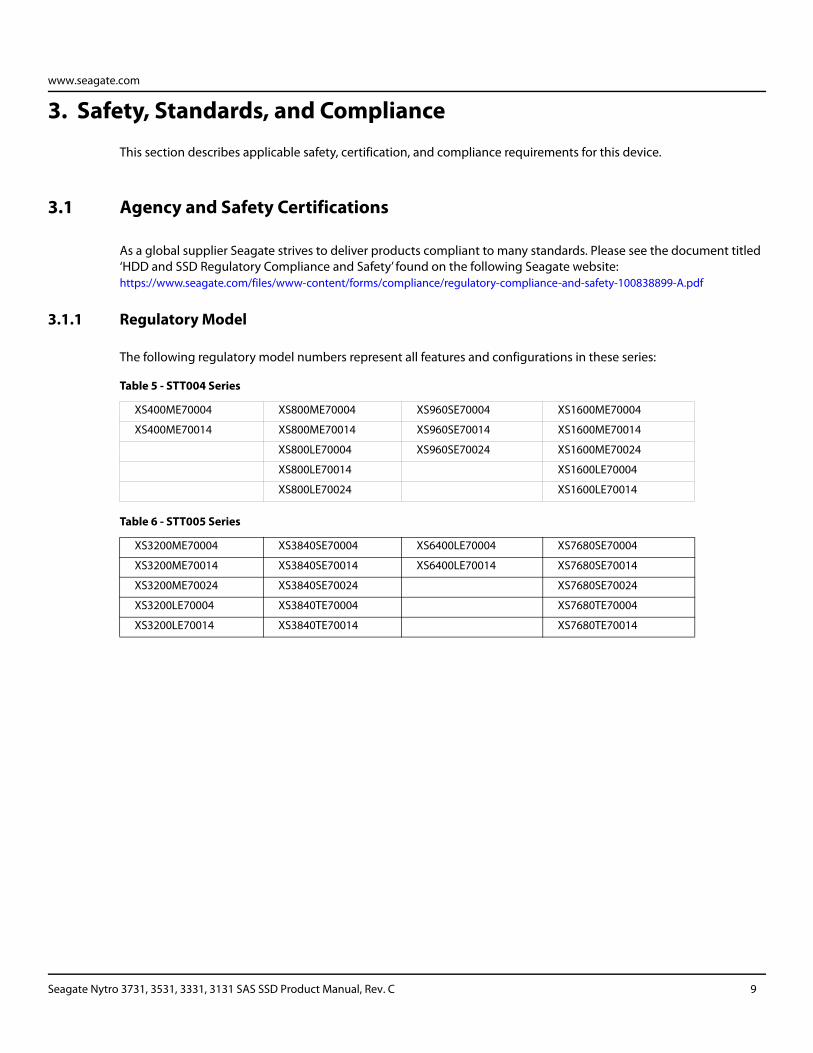
3.1.1 Regulatory Model
The following regulatory model numbers represent all features and configurations in these series:
Table 5 - STT004 Series
XS400ME70004 XS800ME70004 XS960SE70004 XS1600ME70004
XS400ME70014 XS800ME70014 XS960SE70014 XS1600ME70014
XS800LE70004 XS960SE70024 XS1600ME70024
XS800LE70014 XS1600LE70004
XS800LE70024 XS1600LE70014
Table 6 - STT005 Series
XS3200ME70004 XS3840SE70004 XS6400LE70004 XS7680SE70004
XS3200ME70014 XS3840SE70014 XS6400LE70014 XS7680SE70014
XS3200ME70024 XS3840SE70024 XS7680SE70024
XS3200LE70004 XS3840TE70004 XS7680TE70004
XS3200LE70014 XS3840TE70014 XS7680TE70014
Seagate Nytro 3731, 3531, 3331, 3131 SAS SSD Product Manual, Rev. C 9
www.seagate.com
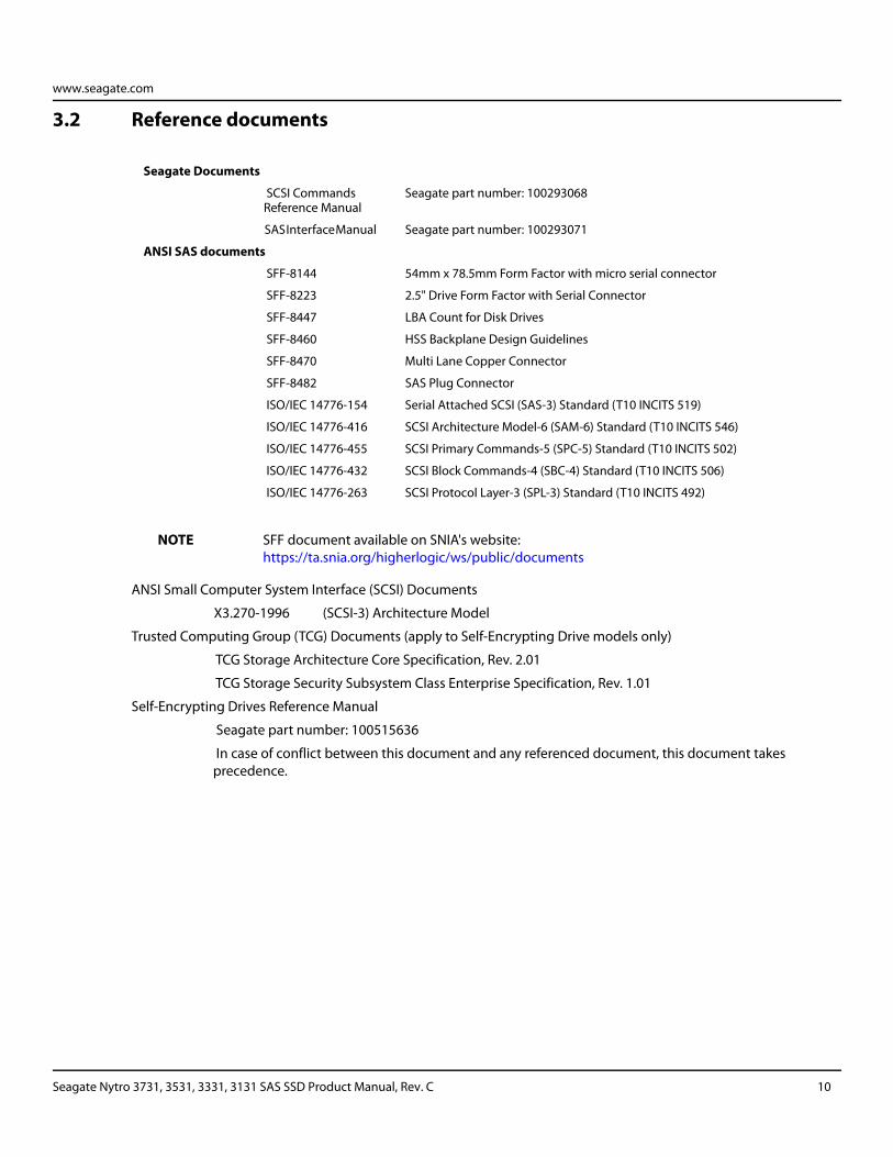
3.2 Reference documents
NOTE SFF document available on SNIA's website: https://ta.snia.org/higherlogic/ws/public/documents
Seagate Documents
SCSI Commands Reference Manual
Seagate part number: 100293068
SAS Interface Manual Seagate part number: 100293071
ANSI SAS documents
SFF-8144 54mm x 78.5mm Form Factor with micro serial connector
SFF-8223 2.5" Drive Form Factor with Serial Connector
SFF-8447 LBA Count for Disk Drives
SFF-8460 HSS Backplane Design Guidelines
SFF-8470 Multi Lane Copper Connector
SFF-8482 SAS Plug Connector
ISO/IEC 14776-154 Serial Attached SCSI (SAS-3) Standard (T10 INCITS 519)
ISO/IEC 14776-416 SCSI Architecture Model-6 (SAM-6) Standard (T10 INCITS 546)
ISO/IEC 14776-455 SCSI Primary Commands-5 (SPC-5) Standard (T10 INCITS 502)
ISO/IEC 14776-432 SCSI Block Commands-4 (SBC-4) Standard (T10 INCITS 506)
ISO/IEC 14776-263 SCSI Protocol Layer-3 (SPL-3) Standard (T10 INCITS 492)
ANSI Small Computer System Interface (SCSI) Documents
X3.270-1996 (SCSI-3) Architecture Model
Trusted Computing Group (TCG) Documents (apply to Self-Encrypting Drive models only)
TCG Storage Architecture Core Specification, Rev. 2.01
TCG Storage Security Subsystem Class Enterprise Specification, Rev. 1.01
Self-Encrypting Drives Reference Manual
Seagate part number: 100515636
In case of conflict between this document and any referenced document, this document takes precedence.
Seagate Nytro 3731, 3531, 3331, 3131 SAS SSD Product Manual, Rev. C 10
www.seagate.com
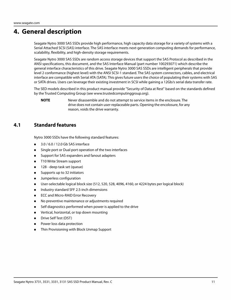
4. General description
Seagate Nytro 3000 SAS SSDs provide high performance, high capacity data storage for a variety of systems with a Serial Attached SCSI (SAS) interface. The SAS interface meets next-generation computing demands for performance, scalability, flexibility, and high-density storage requirements.
Seagate Nytro 3000 SAS SSDs are random access storage devices that support the SAS Protocol as described in the ANSI specifications, this document, and the SAS Interface Manual (part number 100293071) which describe the general interface characteristics of this drive. Seagate Nytro 3000 SAS SSDs are intelligent peripherals that provide level 2 conformance (highest level) with the ANSI SCSI-1 standard. The SAS system connectors, cables, and electrical interface are compatible with Serial ATA (SATA). This gives future users the choice of populating their systems with SAS or SATA drives. Users can leverage their existing investment in SCSI while gaining a 12Gb/s serial data transfer rate.
The SED models described in this product manual provide "Security of Data at Rest" based on the standards defined by the Trusted Computing Group (see www.trustedcomputinggroup.org).
NOTE Never disassemble and do not attempt to service items in the enclosure. The drive does not contain user-replaceable parts. Opening the encolosure, for any reason, voids the drive warranty.
4.1 Standard features
Nytro 3000 SSDs have the following standard features:
3.0 / 6.0 / 12.0 Gb SAS interface
Single port or Dual port operation of the two interfaces
Support for SAS expanders and fanout adapters
T10 Write Stream support
128 - deep task set (queue)
Supports up to 32 initiators
Jumperless configuration
User-selectable logical block size (512, 520, 528, 4096, 4160, or 4224 bytes per logical block)
Industry standard SFF 2.5-inch dimensions
ECC and Micro-RAID Error Recovery
No preventive maintenance or adjustments required
Self diagnostics performed when power is applied to the drive
Vertical, horizontal, or top down mounting
Drive Self Test (DST)
Power loss data protection
Thin Provisioning with Block Unmap Support
Seagate Nytro 3731, 3531, 3331, 3131 SAS SSD Product Manual, Rev. C 11
www.seagate.com
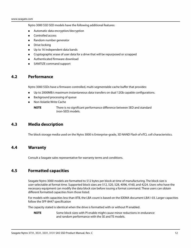
Nytro 3000 SSD SED models have the following additional features:
Automatic data encryption/decryption
Controlled access
Random number generator
Drive locking
Up to 16 independent data bands
Cryptographic erase of user data for a drive that will be repurposed or scrapped
Authenticated firmware download
SANITIZE command support
4.2 Performance
Nytro 3000 SSDs have a firmware-controlled, multi-segmentable cache buffer that provides:
Up to 2000MB/s maximum instantaneous data transfers on dual 12Gb capable configurations.
Background processing of queue
Non-Volatile Write Cache
NOTE There is no significant performance difference between SED and standard (non-SED) models.
4.3 Media description
The block storage media used on the Nytro 3000 is Enterprise-grade, 3D NAND Flash of eTCL cell characteristics.
4.4 Warranty
Consult a Seagate sales representative for warranty terms and conditions.
4.5 Formatted capacities
Seagate Nytro 3000 models are formatted to 512 bytes per block at time of manufacturing. The block size is user-selectable at format time. Supported block sizes are 512, 520, 528, 4096, 4160, and 4224. Users who have the necessary equipment can modify the data block size before issuing a format command. These users can obtain different formatted capacities from those listed.
For models with capacities less than 8TB, the LBA count is based on the IDEMA document LBA1-03. Larger capacities follow the SFF-8447 specification
The capacity stated is identical when the drive is formatted with or without PI enabled.
NOTE Some block sizes with PI enable might cause minor reductions in endurance and random performance with the SE and TE models.
Seagate Nytro 3731, 3531, 3331, 3131 SAS SSD Product Manual, Rev. C 12
www.seagate.com
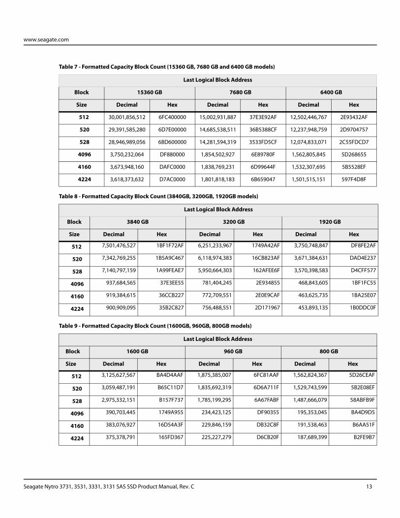
Table 7 - Formatted Capacity Block Count (15360 GB, 7680 GB and 6400 GB models)
Last Logical Block Address
Block 15360 GB 7680 GB 6400 GB
Size Decimal Hex Decimal Hex Decimal Hex
512 30,001,856,512 6FC400000 15,002,931,887 37E3E92AF 12,502,446,767 2E93432AF
520 29,391,585,280 6D7E00000 14,685,538,511 36B5388CF 12,237,948,759 2D9704757
528 28,946,989,056 6BD600000 14,281,594,319 3533FD5CF 12,074,833,071 2C55FDCD7
4096 3,750,232,064 DF880000 1,854,502,927 6E89780F 1,562,805,845 5D268655
4160 3,673,948,160 DAFC0000 1,838,769,231 6D99644F 1,532,307,695 5B5528EF
4224 3,618,373,632 D7AC0000 1,801,818,183 6B659047 1,501,515,151 597F4D8F
Table 8 - Formatted Capacity Block Count (3840GB, 3200GB, 1920GB models)
Last Logical Block Address
Block 3840 GB 3200 GB 1920 GB
Size Decimal Hex Decimal Hex Decimal Hex
512 7,501,476,527 1BF1F72AF 6,251,233,967 1749A42AF 3,750,748,847 DF8FE2AF
520 7,342,769,255 1B5A9C467 6,118,974,383 16CB823AF 3,671,384,631 DAD4E237
528 7,140,797,159 1A99FEAE7 5,950,664,303 162AFEE6F 3,570,398,583 D4CFF577
4096 937,684,565 37E3EE55 781,404,245 2E934855 468,843,605 1BF1FC55
4160 919,384,615 36CCB227 772,709,551 2E0E9CAF 463,625,735 1BA25E07
4224 900,909,095 35B2C827 756,488,551 2D171967 453,893,135 1B0DDC0F
Table 9 - Formatted Capacity Block Count (1600GB, 960GB, 800GB models)
Last Logical Block Address
Block 1600 GB 960 GB 800 GB
Size Decimal Hex Decimal Hex Decimal Hex
512 3,125,627,567 BA4D4AAF 1,875,385,007 6FC81AAF 1,562,824,367 5D26CEAF
520 3,059,487,191 B65C11D7 1,835,692,319 6D6A711F 1,529,743,599 5B2E08EF
528 2,975,332,151 B157F737 1,785,199,295 6A67FABF 1,487,666,079 58ABFB9F
4096 390,703,445 1749A955 234,423,125 DF90355 195,353,045 BA4D9D5
4160 383,076,927 16D54A3F 229,846,159 DB32C8F 191,538,463 B6AA51F
4224 375,378,791 165FD367 225,227,279 D6CB20F 187,689,399 B2FE9B7
Seagate Nytro 3731, 3531, 3331, 3131 SAS SSD Product Manual, Rev. C 13
www.seagate.com
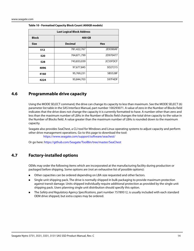
4.6 Programmable drive capacity
Using the MODE SELECT command, the drive can change its capacity to less than maximum. See the MODE SELECT (6) parameter list table in the SAS Interface Manual, part number 100293071. A value of zero in the Number of Blocks field indicates that the drive does not change the capacity it is currently formatted to have. A number other than zero and less than the maximum number of LBAs in the Number of Blocks field changes the total drive capacity to the value in the Number of Blocks field. A value greater than the maximum number of LBAs is rounded down to the maximum capacity.
Seagate also provides SeaChest, a CLI tool for Windows and Linux operating systems to adjust capacity and perform other drive management operations. Go to this page to download the tool:
https://www.seagate.com/support/software/seachest/
Or go here: https://github.com/Seagate/ToolBin/tree/master/SeaChest
4.7 Factory-installed options
OEMs may order the following items which are incorporated at the manufacturing facility during production or packaged before shipping. Some options are (not an exhaustive list of possible options):
Other capacities can be ordered depending on LBA size requested and other factors.
Single-unit shipping pack. The drive is normally shipped in bulk packaging to provide maximum protection against transit damage. Units shipped individually require additional protection as provided by the single unit shipping pack. Users planning single unit distribution should specify this option.
The Safety and Regulatory Agency Specifications, part number 75789512, is usually included with each standard OEM drive shipped, but extra copies may be ordered.
Table 10 - Formatted Capacity Block Count (400GB models)
Last Logical Block Address
Block 400 GB
Size Decimal Hex
512 781,422,767 2E9390AF
520 764,871,799 2D970477
528 743,833,039 2C55FDCF
4096 97,677,845 5D27215
4160 95,769,231 5B5528F
4224 93,844,703 597F4DF
Seagate Nytro 3731, 3531, 3331, 3131 SAS SSD Product Manual, Rev. C 14
www.seagate.com
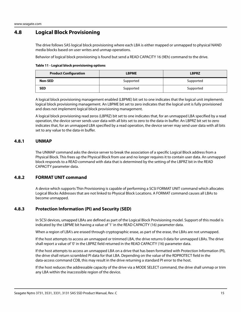
4.8 Logical Block Provisioning
The drive follows SAS logical block provisioning where each LBA is either mapped or unmapped to physical NAND media blocks based on user writes and unmap operations.
Behavior of logical block provisioning is found but send a READ CAPACITY 16 (9Eh) command to the drive.
A logical block provisioning management enabled (LBPME) bit set to one indicates that the logical unit implements logical block provisioning management. An LBPME bit set to zero indicates that the logical unit is fully provisioned and does not implement logical block provisioning management.
A logical block provisioning read zeros (LBPRZ) bit set to one indicates that, for an unmapped LBA specified by a read operation, the device server sends user data with all bits set to zero to the data-in buffer. An LBPRZ bit set to zero indicates that, for an unmapped LBA specified by a read operation, the device server may send user data with all bits set to any value to the data-in buffer.
4.8.1 UNMAP
The UNMAP command asks the device server to break the association of a specific Logical Block address from a Physical Block. This frees up the Physical Block from use and no longer requires it to contain user data. An unmapped block responds to a READ command with data that is determined by the setting of the LBPRZ bit in the READ CAPACITY parameter data.
4.8.2 FORMAT UNIT command
A device which supports Thin Provisioning is capable of performing a SCSI FORMAT UNIT command which allocates Logical Blocks Addresses that are not linked to Physical Block Locations. A FORMAT command causes all LBAs to become unmapped.
4.8.3 Protection Information (PI) and Security (SED)
In SCSI devices, umapped LBAs are defined as part of the Logical Block Provisioning model. Support of this model is indicated by the LBPME bit having a value of '1' in the READ CAPACITY (16) parameter data.
When a region of LBA's are erased through cryptographic erase, as part of the erase, the LBAs are not unmapped.
If the host attempts to access an unmapped or trimmed LBA, the drive returns 0 data for unmapped LBAs. The drive shall report a value of '0' in the LBPRZ field returned in the READ CAPACITY (16) parameter data.
If the host attempts to access an unmapped LBA on a drive that has been formatted with Protection Information (PI), the drive shall return scrambled PI data for that LBA. Depending on the value of the RDPROTECT field in the data-access command CDB, this may result in the drive returning a standard PI error to the host.
If the host reduces the addressable capacity of the drive via a MODE SELECT command, the drive shall unmap or trim any LBA within the inaccessible region of the device.
Table 11 - Logical block provisioning options
Product Configuration LBPME LBPRZ
Non-SED Supported Supported
SED Supported Supported
Seagate Nytro 3731, 3531, 3331, 3131 SAS SSD Product Manual, Rev. C 15
www.seagate.com
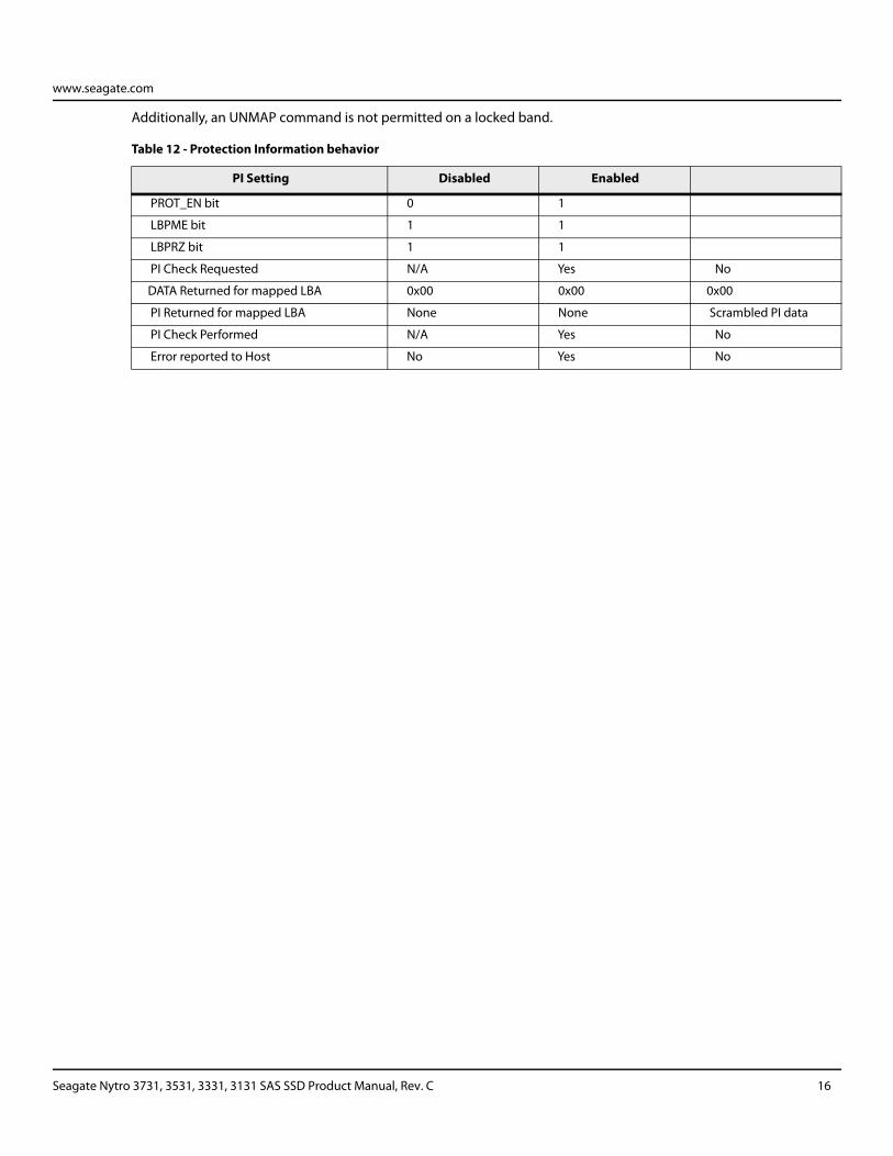
Additionally, an UNMAP command is not permitted on a locked band.
Table 12 - Protection Information behavior
PI Setting Disabled Enabled
PROT_EN bit 0 1
LBPME bit 1 1
LBPRZ bit 1 1
PI Check Requested N/A Yes No
DATA Returned for mapped LBA 0x00 0x00 0x00
PI Returned for mapped LBA None None Scrambled PI data
PI Check Performed N/A Yes No
Error reported to Host No Yes No
Seagate Nytro 3731, 3531, 3331, 3131 SAS SSD Product Manual, Rev. C 16
www.seagate.com
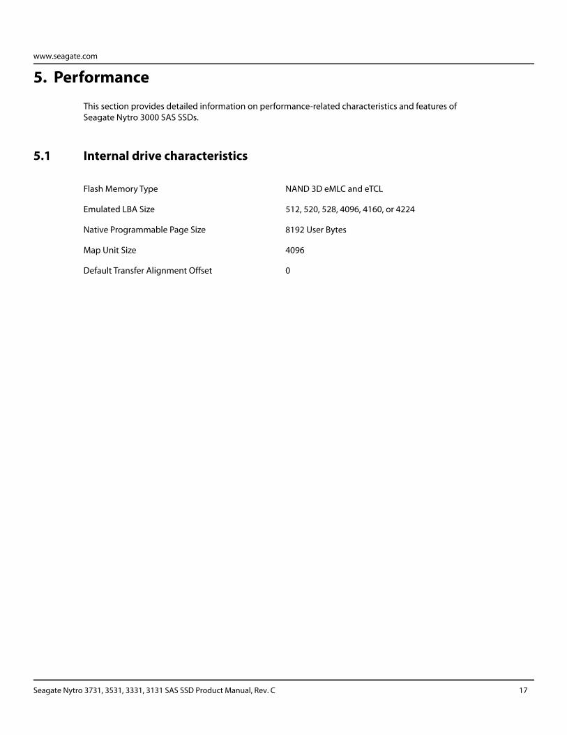
5. Performance
This section provides detailed information on performance-related characteristics and features of Seagate Nytro 3000 SAS SSDs.
5.1 Internal drive characteristics
Flash Memory Type NAND 3D eMLC and eTCL
Emulated LBA Size 512, 520, 528, 4096, 4160, or 4224
Native Programmable Page Size 8192 User Bytes
Map Unit Size 4096
Default Transfer Alignment Offset 0
Seagate Nytro 3731, 3531, 3331, 3131 SAS SSD Product Manual, Rev. C 17
www.seagate.com
5.2 Performance characteristics
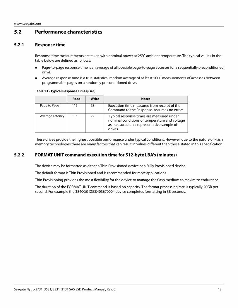
5.2.1 Response time
Response time measurements are taken with nominal power at 25°C ambient temperature. The typical values in the table below are defined as follows:
Page-to-page response time is an average of all possible page-to-page accesses for a sequentially preconditioned drive.
Average response time is a true statistical random average of at least 5000 measurements of accesses between programmable pages on a randomly preconditioned drive.
These drives provide the highest possible performance under typical conditions. However, due to the nature of Flash memory technologies there are many factors that can result in values different than those stated in this specification.
5.2.2 FORMAT UNIT command execution time for 512-byte LBA's (minutes)
The device may be formatted as either a Thin Provisioned device or a Fully Provisioned device.
The default format is Thin Provisioned and is recommended for most applications.
Thin Provisioning provides the most flexibility for the device to manage the flash medium to maximize endurance.
The duration of the FORMAT UNIT command is based on capacity. The format processing rate is typically 20GB per second. For example the 3840GB XS3840SE70004 device completes formatting in 38 seconds.
Table 13 - Typical Response Time (μsec)
Read Write Notes
Page to Page 115 25 Execution time measured from receipt of the Command to the Response. Assumes no errors.
Average Latency 115 25 Typical response times are measured under nominal conditions of temperature and voltage as measured on a representative sample of drives.
Seagate Nytro 3731, 3531, 3331, 3131 SAS SSD Product Manual, Rev. C 18
www.seagate.com
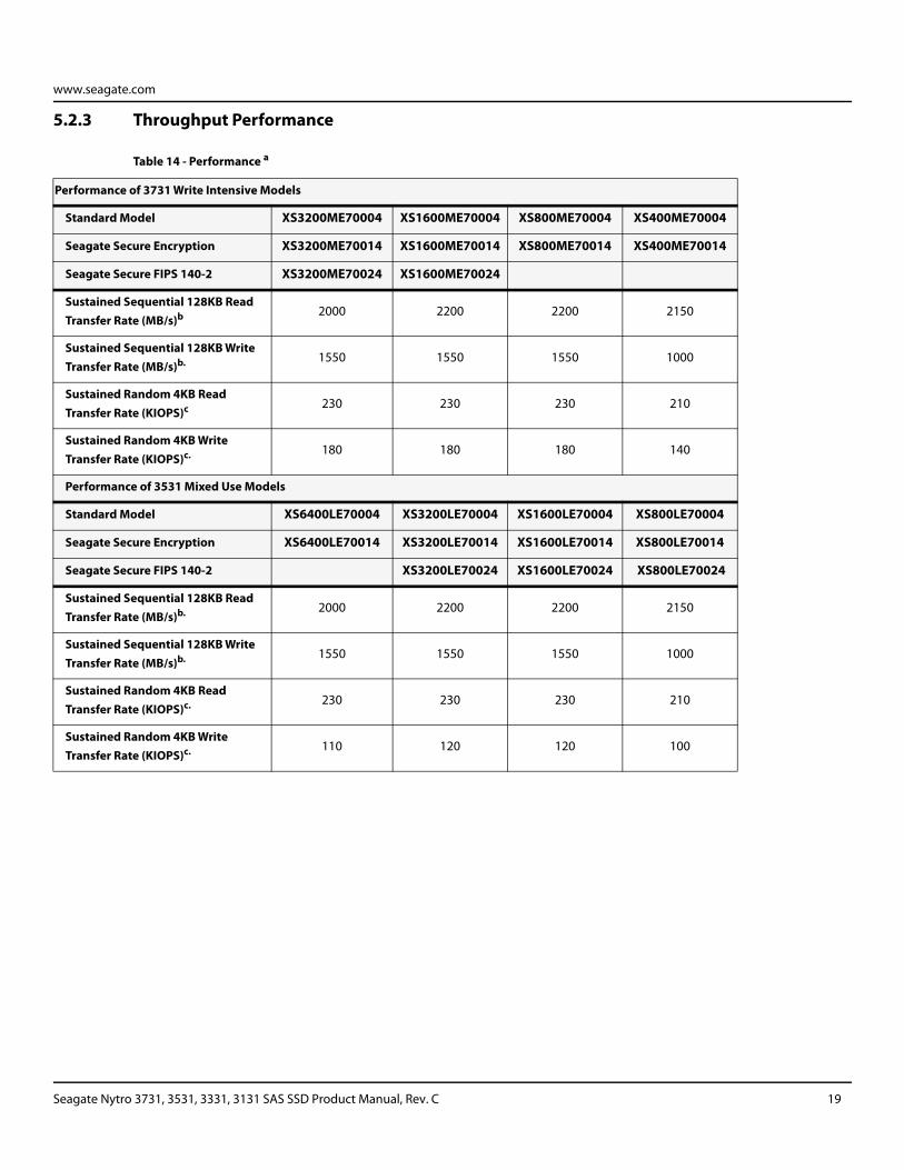
5.2.3 Throughput Performance
Table 14 - Performance a
Performance of 3731 Write Intensive Models
Standard Model XS3200ME70004 XS1600ME70004 XS800ME70004 XS400ME70004
Seagate Secure Encryption XS3200ME70014 XS1600ME70014 XS800ME70014 XS400ME70014
Seagate Secure FIPS 140-2 XS3200ME70024 XS1600ME70024
Sustained Sequential 128KB Read Transfer Rate (MB/s)b 2000 2200 2200 2150
Sustained Sequential 128KB Write Transfer Rate (MB/s)b. 1550 1550 1550 1000
Sustained Random 4KB Read Transfer Rate (KIOPS)c 230 230 230 210
Sustained Random 4KB Write Transfer Rate (KIOPS)c. 180 180 180 140
Performance of 3531 Mixed Use Models
Standard Model XS6400LE70004 XS3200LE70004 XS1600LE70004 XS800LE70004
Seagate Secure Encryption XS6400LE70014 XS3200LE70014 XS1600LE70014 XS800LE70014
Seagate Secure FIPS 140-2 XS3200LE70024 XS1600LE70024 XS800LE70024
Sustained Sequential 128KB Read Transfer Rate (MB/s)b. 2000 2200 2200 2150
Sustained Sequential 128KB Write Transfer Rate (MB/s)b. 1550 1550 1550 1000
Sustained Random 4KB Read Transfer Rate (KIOPS)c. 230 230 230 210
Sustained Random 4KB Write Transfer Rate (KIOPS)c. 110 120 120 100
Seagate Nytro 3731, 3531, 3331, 3131 SAS SSD Product Manual, Rev. C 19
www.seagate.com
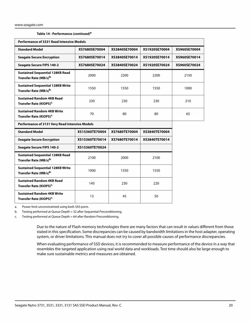
Due to the nature of Flash memory technologies there are many factors that can result in values different from those stated in this specification. Some discrepancies can be caused by bandwidth limitations in the host adapter, operating system, or driver limitations. This manual does not try to cover all possible causes of performance discrepancies.
When evaluating performance of SSD devices, it is recommended to measure performance of the device in a way that resembles the targeted application using real world data and workloads. Test time should also be large enough to make sure sustainable metrics and measures are obtained.
Performance of 3331 Read Intensive Models
Standard Model XS7680SE70004 XS3840SE70004 XS1920SE70004 XS960SE70004
Seagate Secure Encryption XS7680SE70014 XS3840SE70014 XS1920SE70014 XS960SE70014
Seagate Secure FIPS 140-2 XS7680SE70024 XS3840SE70024 XS1920SE70024 XS960SE70024
Sustained Sequential 128KB Read Transfer Rate (MB/s)b. 2000 2200 2200 2150
Sustained Sequential 128KB Write Transfer Rate (MB/s)b. 1550 1550 1550 1000
Sustained Random 4KB Read Transfer Rate (KIOPS)c. 230 230 230 210
Sustained Random 4KB Write Transfer Rate (KIOPS)c. 70 80 80 65
Performance of 3131 Very Read Intensive Models
Standard Model XS15360TE70004 XS7680TE70004 XS3840TE70004
Seagate Secure Encryption XS15360TE70014 XS7680TE70014 XS3840TE70014
Seagate Secure FIPS 140-2 XS15360TE70024
Sustained Sequential 128KB Read Transfer Rate (MB/s)b. 2100 2000 2100
Sustained Sequential 128KB Write Transfer Rate (MB/s)b. 1000 1550 1550
Sustained Random 4KB Read Transfer Rate (KIOPS)c. 145 230 220
Sustained Random 4KB Write Transfer Rate (KIOPS)c. 13 45 50
a. Power limit unconstrainted using both SAS ports.
b. Testing performed at Queue Depth = 32 after Sequential Preconditioning.
c. Testing performed at Queue Depth = 64 after Random Preconditioning.
Table 14 - Performance (continued)a
Seagate Nytro 3731, 3531, 3331, 3131 SAS SSD Product Manual, Rev. C 20
www.seagate.com
5.3 Start/stop time
The drive accepts the commands listed in the SAS Interface Manual less than four seconds after DC power is applied.
If the drive receives a NOTIFY (ENABLE SPINUP) primitive through either port and has not received a START STOP UNIT command with the START bit equal to 0, the drive becomes ready for normal operations within 10 seconds (excluding the error recovery procedure).
If the drive receives a START STOP UNIT command with the START bit equal to 0 before receiving a NOTIFY (ENABLE SPINUP) primitive, the drive waits for a START STOP UNIT command with the START bit equal to 1. After receiving a START STOP UNIT command with the START bit equal to 1, the drive waits for a NOTIFY (ENABLE SPINUP) primitive. After receiving a NOTIFY (ENABLE SPINUP) primitive through either port, the drive becomes ready for normal operations within 5 seconds.
If the drive receives a START STOP UNIT command with the START bit and IMMED bit equal to 1 and does not receive a NOTIFY (ENABLE SPINUP) primitive within 5 seconds, the drive fails the START STOP UNIT command.
The START STOP UNIT command may be used to command the drive to stop. Stop time is three seconds (maximum) from removal of DC power. SCSI stop time is three seconds.
The drive support pin 3 POWER DISABLE as defined by the SAS4 specification.
5.3.1 Caching write data
All write data is stored in non-volatile memory before acknowledging the SAS write operation. Non-volatile memory is both NAND and DRAM that is written to NAND during any power interruption.
The drive never sends a deferred write error status.
The Write Cache Enable (WCE) bit in mode page 08h may be set to 0 or 1 but does not change the operation of the drive.
The SYNCHRONIZE_CACHE command does not alter the state or location of written data. The response from the drive for this command indicates that all prior write commands have been completed and acknowledged.
Section Section 12.3.2 MODE SENSE data, on page 78 shows the mode default settings for the drive.
Seagate Nytro 3731, 3531, 3331, 3131 SAS SSD Product Manual, Rev. C 21
www.seagate.com
5.3.2 Prefetch operation
If the Prefetch feature is enabled, data in contiguous logical blocks on the medium immediately beyond what was requested by a Read command are retrieved and stored in the buffer for immediate transfer from the buffer to the host on subsequent Read commands that request those logical blocks (this is true even if cache operation is disabled). Though the prefetch operation uses the buffer as a cache, finding the requested data in the buffer is a prefetch hit, not a cache operation hit.
To enable Prefetch, use Mode Select page 08h, byte 12, bit 5 (Disable Read Ahead - DRA bit). DRA bit = 0 enables prefetch.
The drive does not use the Max Prefetch field (bytes 8 and 9) or the Prefetch Ceiling field (bytes 10 and 11).
When prefetch (read look-ahead) is enabled (enabled by DRA = 0), the drive enables prefetch of contiguous blocks from the medium when it senses that a prefetch hit will likely occur. The drive disables prefetch when it decides that a prefetch hit is not likely to occur.
Seagate Nytro 3731, 3531, 3331, 3131 SAS SSD Product Manual, Rev. C 22
www.seagate.com
6. Reliability specifications
These reliability specifications assume correct host and drive operational interface, including all interface timings, power supply voltages, environmental requirements, and drive mounting constraints.
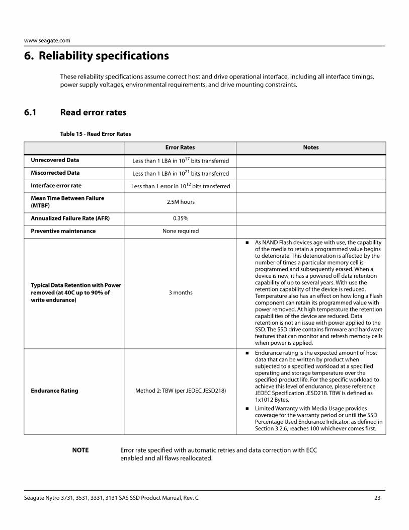
6.1 Read error rates
NOTE Error rate specified with automatic retries and data correction with ECC enabled and all flaws reallocated.
Table 15 - Read Error Rates
Error Rates Notes
Unrecovered Data Less than 1 LBA in 1017 bits transferred
Miscorrected Data Less than 1 LBA in 1021 bits transferred
Interface error rate Less than 1 error in 1012 bits transferred
Mean Time Between Failure (MTBF) 2.5M hours
Annualized Failure Rate (AFR) 0.35%
Preventive maintenance None required
Typical Data Retention with Power removed (at 40C up to 90% of write endurance)
3 months
As NAND Flash devices age with use, the capability of the media to retain a programmed value begins to deteriorate. This deterioration is affected by the number of times a particular memory cell is programmed and subsequently erased. When a device is new, it has a powered off data retention capability of up to several years. With use the retention capability of the device is reduced. Temperature also has an effect on how long a Flash component can retain its programmed value with power removed. At high temperature the retention capabilities of the device are reduced. Data retention is not an issue with power applied to the SSD. The SSD drive contains firmware and hardware features that can monitor and refresh memory cells when power is applied.
Endurance Rating Method 2: TBW (per JEDEC JESD218)
Endurance rating is the expected amount of host data that can be written by product when subjected to a specified workload at a specified operating and storage temperature over the specified product life. For the specific workload to achieve this level of endurance, please reference JEDEC Specification JESD218. TBW is defined as 1x10¹² Bytes.
Limited Warranty with Media Usage provides coverage for the warranty period or until the SSD Percentage Used Endurance Indicator, as defined in Section 3.2.6, reaches 100 whichever comes first.
Seagate Nytro 3731, 3531, 3331, 3131 SAS SSD Product Manual, Rev. C 23
www.seagate.com
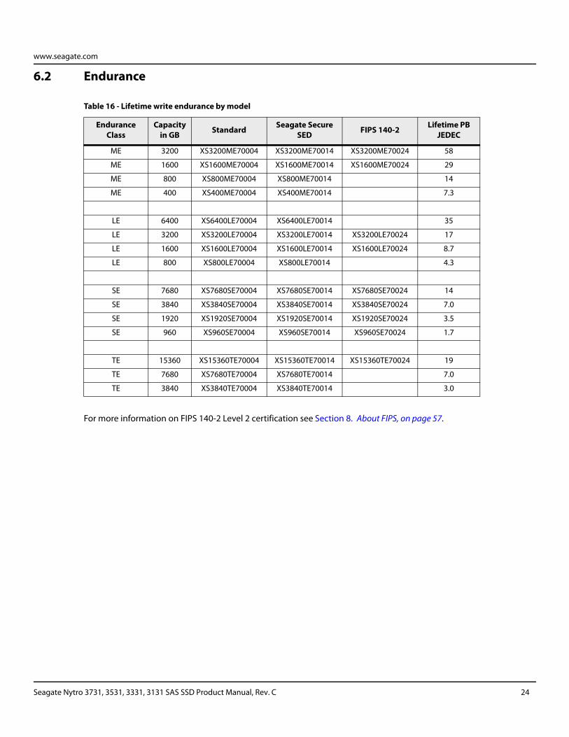
6.2 Endurance
For more information on FIPS 140-2 Level 2 certification see Section 8. About FIPS, on page 57.
Table 16 - Lifetime write endurance by model
Endurance Class
Capacity in GB Standard Seagate Secure
SED FIPS 140-2 Lifetime PB JEDEC
ME 3200 XS3200ME70004 XS3200ME70014 XS3200ME70024 58
ME 1600 XS1600ME70004 XS1600ME70014 XS1600ME70024 29
ME 800 XS800ME70004 XS800ME70014 14
ME 400 XS400ME70004 XS400ME70014 7.3
LE 6400 XS6400LE70004 XS6400LE70014 35
LE 3200 XS3200LE70004 XS3200LE70014 XS3200LE70024 17
LE 1600 XS1600LE70004 XS1600LE70014 XS1600LE70024 8.7
LE 800 XS800LE70004 XS800LE70014 4.3
SE 7680 XS7680SE70004 XS7680SE70014 XS7680SE70024 14
SE 3840 XS3840SE70004 XS3840SE70014 XS3840SE70024 7.0
SE 1920 XS1920SE70004 XS1920SE70014 XS1920SE70024 3.5
SE 960 XS960SE70004 XS960SE70014 XS960SE70024 1.7
TE 15360 XS15360TE70004 XS15360TE70014 XS15360TE70024 19
TE 7680 XS7680TE70004 XS7680TE70014 7.0
TE 3840 XS3840TE70004 XS3840TE70014 3.0
Seagate Nytro 3731, 3531, 3331, 3131 SAS SSD Product Manual, Rev. C 24
www.seagate.com
6.3 Error rates
The error rates stated in this manual assume the following:
The drive is operated in accordance with this manual using DC power as defined in Section 7.2 Power consumption, on page 33.
Errors caused by host system failures are excluded from error rate computations.
Assume random data.
Default OEM error recovery settings are applied. This includes AWRE, ARRE, full read retries, full write retries and full retry time.
6.3.1 Unrecoverable Errors
An unrecoverable data error is a failure of the drive to recover data from the media. These errors occur due to read or write problems. Unrecoverable data errors are only detected during read operations, but not caused by the read. If an unrecoverable data error is detected, a MEDIUM ERROR (03h) in the Sense Key is reported. Multiple unrecoverable data errors resulting from the same cause are treated as one error.
6.3.2 Interface errors
An interface error is defined as a failure of the receiver on a port to recover the data as transmitted by the device port connected to the receiver. The error may be detected as a running disparity error, illegal code, loss of word sync, or CRC error.
6.4 Endurance management
Customer satisfaction with Solid State Drives can be directly related to the internal algorithms which an SSD uses to manage the limited number of Program-Erase (PE) cycles that NAND Flash can withstand. These algorithms consist of Wear Leveling, Garbage Collection, Write Amplification, Unmap, Data Retention, Lifetime Endurance Management.
6.4.1 Wear leveling
The drive uses Wear Leveling to make sure that all Flash cells are written to or exercised as evenly as possible to avoid hot spots where some cells are used up faster than other locations. The drive automatically manages Wear Leveling without user interaction. The Seagate algorithm operates only when needed to ensure reliable product operation.
6.4.2 Garbage collection
The drive uses Garbage Collection to consolidate valid user data into a common cell range freeing up unused or obsolete locations to be erased and used for future storage needs. The drive automatically manages Garbage Collection without user interaction. The Seagate algorithm operates only when needed to ensure reliable product operation.
Seagate Nytro 3731, 3531, 3331, 3131 SAS SSD Product Manual, Rev. C 25
www.seagate.com
6.4.3 Write amplification
While Write Amplification is not an algorithm, it is a major characteristic of SSDs. Write Amplification must be accounted for by all the algorithms that the SSD implements. The Write Amplification Factor of an SSD is the ratio of Host/User data requested to be written to the actual amount of data written by the SSD internal to account for the user data and the housekeeping activities such as Wear Leveling and Garbage Collection. The Write Amplification Factor of an SSD can also be directly affected by the characteristics of the host data being sent to the SSD to write. The best Write Amplification Factor is achieved for data that is written in sequential LBAs that are aligned on 4KB boundaries. The worst case Write Amplification Factor occurs for randomly written LBA's of transfer sizes that are less than 4KB and that originate on LBA's that are not on 4KB boundaries.
6.4.4 UNMAP
Use of the UNMAP command reduces the Write Amplification Factor of the drive during housekeeping tasks such as Wear Leveling and Garbage Collection. This happens because the drive does not need to retain data which has been classified by the host as obsolete.
6.4.5 Data retention
Data Retention is another major characteristic of SSDs that must be accounted for by all the algorithms that the SSD implements. While powered up, the Data Retention of SSD cells are monitored and rewritten if the cell levels decay to an unexpected level. Data Retention when the drive is powered off is affected by Program and Erase (PE) cycles and the temperature of the drive when stored.
6.4.6 Write stream tagging
The Write Stream command is an optional SAS bus command for the host to pass a contextual data tag to SSD. The SSD stores data context together to minimize write amplification when data is unmapped or over written. The Nytro 3000 supports creating 32 streams but optimal benefit is achieved when 8 or less streams are concurrently active.
6.4.7 SSD percentage used endurance indicator
An application can interrogate the drive through the host to determine an estimate of the percentage of device life that has been used. To accomplish this, issue a LOG SENSE command to log page 0x11. This allows applications to read the contents of the Percentage Used Endurance Indicator parameter code. The Percentage Used Endurance Indicator is defined in the T10 document SBC-4 available from the T10 committee.
6.5 Reliability and service
Integrators can enhance the reliability of Seagate Nytro 3000 SAS SSD drives by ensuring that the drive receives adequate cooling. Section 12.4.2 Physical characteristics, on page 84 provides temperature measurements and other information that may be used to enhance the service life of the drive. Section 11.2 Cooling, on page 66 provides recommended air-flow information.
Seagate Nytro 3731, 3531, 3331, 3131 SAS SSD Product Manual, Rev. C 26
www.seagate.com
6.5.1 Annualized Failure Rate (AFR) and Mean Time Between Failure (MTBF)
The production drive shall achieve an AFR of 0.35% (MTBF of 2,500,000 hours) when operated in an environment that ensures the case temperatures do not exceed the values specified in Section 7.3 Environmental limits, on page 51. Operation at case temperatures outside the specifications in Section 7.3 Environmental limits, on page 51 may increase the product AFR (decrease the MTBF). The AFR (MTBF) is a population statistic not relevant to individual units.
The AFR (MTBF) specification is based on the following assumptions for Enterprise Storage System environments:
8760 power-on hours per year.
250 average on/off cycles per year.
Operations at nominal voltages.
Systems will provide adequate cooling to ensure the case temperatures specified in Section 11.2 Cooling, on page 66 are not exceeded. Temperatures outside the specifications in Section 11.2 Cooling, on page 66 will increase the product AFR and decrease the MTBF.
6.5.2 Preventive maintenance
No routine scheduled preventive maintenance is required.
6.5.3 Hot plugging the drive
When a drive is powered on by switching the power or hot plugged, the drive runs a self test before attempting to communicate on its' interfaces. When the self test completes successfully, the drive initiates a Link Reset starting with the Out Of Band sequence (OOB). An attached device should respond to the link reset. If the link reset attempt fails, or any time the drive looses sync, the drive initiated link reset. The drive will initiate link reset once per second but alternates between port A and B. Therefore each port will attempt a link reset once per 2 seconds assuming both ports are out of sync.
If the self-test fails, the drive does not respond to link reset on the failing port.
NOTE It is the responsibility of the systems integrator to assure that no temperature, energy, voltage hazard, or ESD potential hazard is presented during the hot connect/disconnect operation. Discharge the static electricity from the drive carrier prior to inserting it into the system.
6.5.4 S.M.A.R.T.
S.M.A.R.T. is an acronym for Self-Monitoring Analysis and Reporting Technology. This technology is intended to recognize conditions that indicate imminent drive failure and is designed to provide sufficient warning of a failure to allow administrators to back up the data before an actual failure occurs.
NOTE The drive's firmware monitors specific attributes for degradation over time but can't predict instantaneous drive failures.
Each monitored attribute has been selected to monitor a specific set of failure conditions in the operating performance of the drive and the thresholds are optimized to minimize "false" and "failed" predictions.
Seagate Nytro 3731, 3531, 3331, 3131 SAS SSD Product Manual, Rev. C 27
www.seagate.com
6.5.4.1 Controlling S.M.A.R.T.
The operating mode of S.M.A.R.T. is controlled by the DEXCPT and PERF bits on the Informational Exceptions Control mode page (1Ch). Use the DEXCPT bit to enable or disable the S.M.A.R.T. feature. Setting the DEXCPT bit disables all S.M.A.R.T. functions. When enabled, S.M.A.R.T. collects on-line data as the drive performs normal read and write operations. When the PERF bit is set, the drive is considered to be in "On-line Mode Only" and will not perform off-line functions.
An application can measure off-line attributes and force the drive to save the data by using the REZERO UNIT command. Forcing S.M.A.R.T. resets the timer so that the next scheduled interrupt is in one hour.
An application can interrogate the drive through the host to determine the time remaining before the next scheduled measurement and data logging process occurs. To accomplish this, issue a LOG SENSE command to log page 0x3E. This allows applications to control when S.M.A.R.T. interruptions occur. Forcing S.M.A.R.T. with the REZERO UNIT command resets the timer.
6.5.4.2 Performance impact
S.M.A.R.T. attribute data is saved to the media so that the events that caused a predictive failure can be recreated. The drive measures and saves parameters once every hour subject to an idle period on the drive interfaces. The process of measuring off-line attribute data and saving data to the media is interruptible. The maximum on-line only processing delay is summarized in the following table:
6.5.4.3 Reporting control
Reporting is controlled by the MRIE bits in the Informational Exceptions Control mode page (1Ch). Subject to the reporting method. For example, if the MRIE is set to one, the firmware will issue to the host an 01-5D00 sense code. The FRU field contains the type of predictive failure that occurred. The error code is preserved through bus resets and power cycles.
6.5.4.4 Determining rate
S.M.A.R.T. monitors the rate at which errors occur and signals a predictive failure if the rate of degraded errors increases to an unacceptable level. To determine rate, error events are logged and compared to the number of total operations for a given attribute. The interval defines the number of operations over which to measure the rate. The counter that keeps track of the current number of operations is referred to as the Interval Counter.
S.M.A.R.T. measures error rates. All errors for each monitored attribute are recorded. A counter keeps track of the number of errors for the current interval. This counter is referred to as the Failure Counter.
Error rate is the number of errors per operation. The algorithm that S.M.A.R.T. uses to record rates of error is to set thresholds for the number of errors and appropriate interval. If the number of errors exceeds the threshold before the interval expires, the error rate is considered to be unacceptable. If the number of errors does not exceed the threshold before the interval expires, the error rate is considered to be acceptable. In either case, the interval and failure counters are reset and the process starts over.
6.5.4.5 Predictive failures
S.M.A.R.T. signals predictive failures when the drive is performing unacceptably for a period of time. The firmware keeps a running count of the number of times the error rate for each attribute is unacceptable. To accomplish this, a counter is incremented each time the error rate is unacceptable and decremented (not to exceed zero) whenever the error rate is acceptable. If the counter continually increments such that it reaches the predictive threshold, a predictive failure is signaled. This counter is referred to as the Failure History Counter. There is a separate Failure History Counter for each attribute.
Table 17 - Maximum processing delay
Fully-enabled delay DEXCPT = 0
S.M.A.R.T. delay times 75 ms
Seagate Nytro 3731, 3531, 3331, 3131 SAS SSD Product Manual, Rev. C 28
www.seagate.com
6.5.5 Thermal monitor
Seagate Nytro 3000 SAS SSD drives implement a temperature warning system which:
1. Signals the host if the temperature exceeds a value which would threaten the drive.
2. Signals the host if the temperature exceeds a user-specified value. (i.e., the reference temperature value)
3. Saves a S.M.A.R.T. data frame on the drive which exceeds the threatening temperature value.
A temperature sensor monitors the drive temperature and issues a warning over the interface when the temperature exceeds a set threshold. The temperature is measured at power-up and then at ten-minute intervals after power-up.
The thermal monitor system generates a warning code of 01-0B01 when the temperature exceeds the specified limit in compliance with the SCSI standard.
This feature is controlled by the Enable Warning (EWasc) bit, and the reporting mechanism is controlled by the Method of Reporting Informational Exceptions field (MRIE) on the Informational Exceptions Control (IEC) mode page (1Ch).
6.5.6 Drive Self Test (DST)
Drive Self Test (DST) is a technology designed to recognize drive fault conditions that qualify the drive as a failed unit. DST validates the functionality of the drive at a system level. There are two test coverage options implemented in DST:
1. Extended test
2. Short test
The most thorough option is the extended test that performs various tests on the drive and scans every logical block address (LBA) of the drive. The short test is time-restricted and limited in length--it does not scan the entire media contents, but does some fundamental tests and scans portions of the media. If DST encounters an error during either of these tests, it reports a "diagnostic failed" condition. If the drive fails the test, remove it from service and return it to Seagate for service.
6.5.6.1 DST failure definition
The drive will present a "diagnostic failed" condition through the self-tests results value of the diagnostic log page if a functional failure is encountered during DST. The drive parameters are not modified to test the drive more stringently, and the recovery capabilities are not reduced. All retries and recovery processes are enabled during the test. If data is recoverable, no failure condition will be reported regardless of the recovery processes required to recover the data. The following conditions are considered DST failure conditions:
Read error after recovery attempts are exhausted
Write error after recovery attempts are exhausted
6.5.6.2 Implementation
This section provides all of the information necessary to implement the DST function on this drive.
6.5.6.3 State of the drive prior to testing
The drive must be in a ready state before issuing the SEND DIAGNOSTIC command. There are multiple reasons why a drive may not be ready, some of which are valid conditions, and not errors. For example, a drive may be in process of doing a FORMAT UNIT, or another DST. It is the responsibility of the host application to determine the "not ready" cause.
Seagate Nytro 3731, 3531, 3331, 3131 SAS SSD Product Manual, Rev. C 29
www.seagate.com
6.5.6.4 Invoking DST
To invoke DST, submit the SEND DIAGNOSTIC command with the appropriate Function Code (001b for the short test or 010b for the extended test) in bytes 1, bits 5, 6, and 7. Each test consists of two segments: an electrical test segment and a read/verify scan segment.
DST has two testing options:
Short test (Function Code: 001b)
The purpose of the short test is to provide a time-limited test that tests as much of the drive as possible within 120 seconds. The short test does not scan the entire media contents, but does some fundamental tests and scans portions of the media. A complete read/verify scan is not performed and only factual failures will report a "diagnostic failed" condition. This option provides a quick confidence test of the drive.
Extended test (Function Code: 010b)
The objective of the extended test option is to empirically test critical drive components. The read operation tests the media contents. The integrity of the media is checked through a read/verify scan of the media. The anticipated length of the Extended test is reported through the Control Mode page.
6.5.6.5 Log page entries
When the drive begins DST, it creates a new entry in the Self-test Results Log page. The new entry is created by inserting a new self-test parameter block at the beginning of the self-test results log parameter section of the log page. Existing data will be moved to make room for the new parameter block. The drive reports 20 parameter blocks in the log page. If there are more than 20 parameter blocks, the least recent parameter block will be deleted. The new parameter block will be initialized as follows:
1. The Function Code field is set to the same value as sent in the DST command
2. The Self-Test Results Value field is set to Fh
3. The drive will store the log page to non-volatile memory
After a self-test is complete or has been aborted, the drive updates the Self-Test Results Value field in its Self-Test Results Log page in non-volatile memory. The host may use LOG SENSE to read the results from up to the last 20 self-tests performed by the drive. The self-test results value is a 4-bit field that reports the results of the test. If the field is set to zero, the drive passed with no errors detected by the DST. If the field is not set to zero, the test failed for the reason reported in the field.
The drive will report the failure condition and LBA (if applicable) in the Self-test Results Log parameter. The Sense key, ASC, ASCQ, and FRU are used to report the failure condition.
6.5.6.6 Abort
There are several ways to abort a diagnostic. Applications can use a SCSI Bus Reset or a Bus Device Reset message to abort the diagnostic.
Applications can abort a DST executing in background mode by using the abort code in the DST Function Code field. This will cause a 01 (self-test aborted by the application client) code to appear in the self-test results values log. All other abort mechanisms will be reported as a 02 (self-test routine was interrupted by a reset condition).
6.5.7 Product warranty
For information regarding warranty support details, visit: http://www.seagate.com/support/warranty-and-replacements/
Limited Warranty with Media Usage: This warranty is based on the shorter of term and endurance usage of the drive.
Seagate Nytro 3731, 3531, 3331, 3131 SAS SSD Product Manual, Rev. C 30
www.seagate.com
6.5.8 Shipping
When transporting or shipping a drive, use only a Seagate-approved container. Keep the original box. Seagate approved containers are easily identified by the Seagate Approved Package label. Shipping a drive in a non-approved container voids the drive warranty.
Seagate repair centers may refuse receipt of components improperly packaged or obviously damaged in transit. Contact the authorized Seagate distributor to purchase additional boxes. Seagate recommends shipping by an air-ride carrier experienced in handling computer equipment.
6.5.8.1 Product repair and return information
Seagate customer service centers are the only facilities authorized to service Seagate drives. Seagate does not sanction any third party repair facilities. Any unauthorized repair or tampering with the factory seal voids the warranty.
6.5.8.2 Storage
You can store the drive for a maximum of 180 days in the original unopened Seagate shipping package or 60 days, unpackaged, in the defined non-operating limits (refer to environmental section in this manual). You can extend storage to 1 year packaged or unpackaged under optimal environmental conditions (<40°C, <40% relative humidity non-condensing, and non-corrosive environment). During any storage period you must follow the drive non-operational temperature, humidity, wet bulb, atmospheric conditions, shock, vibration, magnetic and electrical field specifications.
Seagate Nytro 3731, 3531, 3331, 3131 SAS SSD Product Manual, Rev. C 31
www.seagate.com
7. Physical and electrical specifications
This section provides information relating to the physical and electrical characteristics of the drive.
7.1 Power specifications
The 2.5" drive receives DC power (+5V and +12V) through the standard SAS interface. The minimum current loading for each supply voltage is not less than 1.7% of the maximum operating current shown. Both +5V and +12V supplies should employ separate ground returns.
Where power is provided to multiple drives from a common supply, careful consideration for individual drive power requirements should be noted. Where multiple units are powered on simultaneously, the peak starting current must be available to each device.
General DC power requirement notes:
Minimum current loading for each supply voltage is not less than 1.7% of the maximum operating current shown.
The +5V and +12V supplies should employ separate ground returns.
Where power is provided to multiple drives from a common supply, careful consideration for individual drive power requirements should be noted. Where multiple units are powered on simultaneously, the peak starting current must be available to each device.
Parameters, other than start, are measured after a 10-minute warm up.
Table 18 - 12V Requirements
Supply Tolerance +10% / -7%
Absolute Maximum Voltage 15V
Supply Rise Time 0 to 500 ms
Supply Drop Time 0.12 to 500 ms
Typical Capacitance TBD μf
Table 19 - 5V Requirements
Supply Tolerance +10% / -7%
Absolute Maximum Voltage 5.5V
Supply Rise Time 0 to 500 ms
Supply Drop Time 0.05 to 500 ms
Typical Capacitance TBD μf
Seagate Nytro 3731, 3531, 3331, 3131 SAS SSD Product Manual, Rev. C 32
www.seagate.com
7.1.1 Conducted noise immunity
Noise is specified as a periodic and random distribution of frequencies covering a defined frequency. Maximum allowed noise values given below are peak-to-peak measurements and apply at the drive power connector.
7.1.2 Power sequencing
The drive does not require power sequencing. The drive protects against inadvertent writing during power-up and down.
7.2 Power consumption
Power requirements for the drives are listed in the tables in this section. Typical power measurements are based on an average of drives tested, under nominal conditions, using the listed input voltage at 60°C internal temperature.
Startup power
Startup power is measured from the time of power-on to the time that the drive reaches operating condition and can process media access commands.
Peak operating mode
During peak operating mode, the drive is tested in various read and write access patterns to simulate the worst-case power consumption.
Idle mode power
Idle mode power is measured with the drive powered up and ready for media access commands, with no media access commands having been received from the host.
7.2.1 Direct Current Consumption by Voltage Rail
The following tables list the single port active power consumption measured under various workloads for each mode.
Points to be noted about the tables:
Measured with average reading DC ammeter. Instantaneous +12V current peaks will exceed these values. Power supply at nominal voltage. N (number of drives tested) = 6, 60 Degrees C internal.
For +12 V, a -10% tolerance is allowed during initial start but must return to ±5% before reaching ready state. The ±5% must be maintained after the drive signifies that its power-up sequence has been completed and that the drive is able to accept selection by the host initiator.
Delayed Motor Start condition occurs after OOB and Speed Negotiation completes but before the drive has received the Notify Spinup primitive.
See Section 7.1.1 Conducted noise immunity, on page 33. Specified voltage tolerance includes ripple, noise, and transient response.
Table 20 - Maximum allowed peak-to-peak noise
+5 V 250 mV pp from 100 Hz to 20 MHz.
450 mV pp from 100 Hz to 100 KHz.
+12 V 250 mV pp from 100 KHz to 20 MHz.
150 mV pp from 20 MHz to 80 MHz.
Seagate Nytro 3731, 3531, 3331, 3131 SAS SSD Product Manual, Rev. C 33
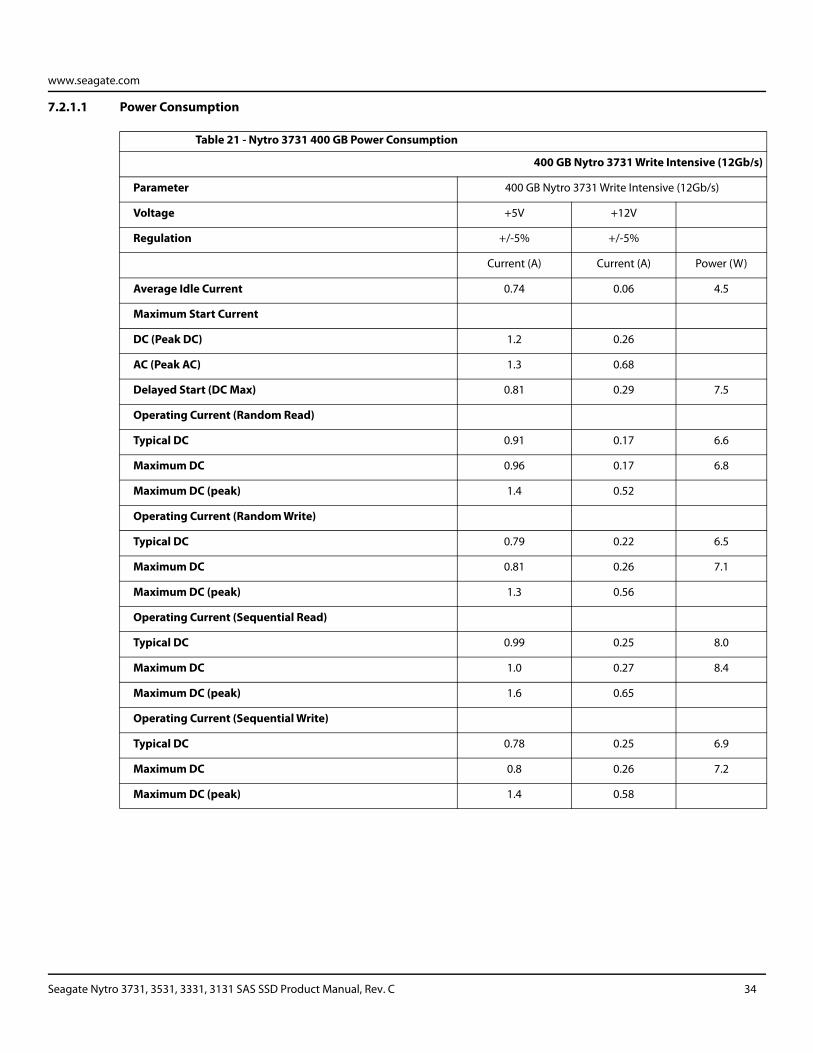
www.seagate.com
7.2.1.1 Power Consumption
Table 21 - Nytro 3731 400 GB Power Consumption
400 GB Nytro 3731 Write Intensive (12Gb/s)
Parameter 400 GB Nytro 3731 Write Intensive (12Gb/s)
Voltage +5V +12V
Regulation +/-5% +/-5%
Current (A) Current (A) Power (W)
Average Idle Current 0.74 0.06 4.5
Maximum Start Current
DC (Peak DC) 1.2 0.26
AC (Peak AC) 1.3 0.68
Delayed Start (DC Max) 0.81 0.29 7.5
Operating Current (Random Read)
Typical DC 0.91 0.17 6.6
Maximum DC 0.96 0.17 6.8
Maximum DC (peak) 1.4 0.52
Operating Current (Random Write)
Typical DC 0.79 0.22 6.5
Maximum DC 0.81 0.26 7.1
Maximum DC (peak) 1.3 0.56
Operating Current (Sequential Read)
Typical DC 0.99 0.25 8.0
Maximum DC 1.0 0.27 8.4
Maximum DC (peak) 1.6 0.65
Operating Current (Sequential Write)
Typical DC 0.78 0.25 6.9
Maximum DC 0.8 0.26 7.2
Maximum DC (peak) 1.4 0.58
Seagate Nytro 3731, 3531, 3331, 3131 SAS SSD Product Manual, Rev. C 34
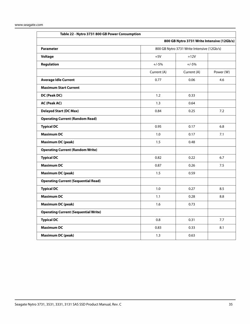
www.seagate.com
Table 22 - Nytro 3731 800 GB Power Consumption
800 GB Nytro 3731 Write Intensive (12Gb/s)
Parameter 800 GB Nytro 3731 Write Intensive (12Gb/s)
Voltage +5V +12V
Regulation +/-5% +/-5%
Current (A) Current (A) Power (W)
Average Idle Current 0.77 0.06 4.6
Maximum Start Current
DC (Peak DC) 1.2 0.33
AC (Peak AC) 1.3 0.64
Delayed Start (DC Max) 0.84 0.25 7.2
Operating Current (Random Read)
Typical DC 0.95 0.17 6.8
Maximum DC 1.0 0.17 7.1
Maximum DC (peak) 1.5 0.48
Operating Current (Random Write)
Typical DC 0.82 0.22 6.7
Maximum DC 0.87 0.26 7.5
Maximum DC (peak) 1.5 0.59
Operating Current (Sequential Read)
Typical DC 1.0 0.27 8.5
Maximum DC 1.1 0.28 8.8
Maximum DC (peak) 1.6 0.73
Operating Current (Sequential Write)
Typical DC 0.8 0.31 7.7
Maximum DC 0.83 0.33 8.1
Maximum DC (peak) 1.3 0.63
Seagate Nytro 3731, 3531, 3331, 3131 SAS SSD Product Manual, Rev. C 35

www.seagate.com
Table 23 - Nytro 3731 1600 GB Power Consumption
1600 GB Nytro 3731 Write Intensive (12Gb/s)
Parameter 1600 GB Nytro 3731 Write Intensive (12Gb/s)
Voltage +5V +12V
Regulation +/-5% +/-5%
Current (A) Current (A) Power (W)
Average Idle Current 0.76 0.06 4.6
Maximum Start Current
DC (Peak DC) 1.2 0.39
AC (Peak AC) 1.4 0.72
Delayed Start (DC Max) 0.8 0.23 6.8
Operating Current (Random Read)
Typical DC 0.97 0.21 7.3
Maximum DC 0.98 0.22 7.6
Maximum DC (peak) 1.6 0.65
Operating Current (Random Write)
Typical DC 0.84 0.27 7.4
Maximum DC 0.87 0.31 8.0
Maximum DC (peak) 1.5 0.68
Operating Current (Sequential Read)
Typical DC 1.0 0.29 8.6
Maximum DC 1.0 0.32 9.1
Maximum DC (peak) 1.6 0.73
Operating Current (Sequential Write)
Typical DC 0.83 0.34 8.2
Maximum DC 0.85 0.37 8.7
Maximum DC (peak) 1.6 0.73
Seagate Nytro 3731, 3531, 3331, 3131 SAS SSD Product Manual, Rev. C 36
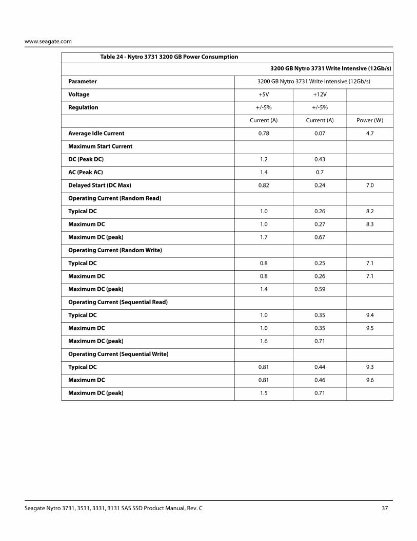
www.seagate.com
Table 24 - Nytro 3731 3200 GB Power Consumption
3200 GB Nytro 3731 Write Intensive (12Gb/s)
Parameter 3200 GB Nytro 3731 Write Intensive (12Gb/s)
Voltage +5V +12V
Regulation +/-5% +/-5%
Current (A) Current (A) Power (W)
Average Idle Current 0.78 0.07 4.7
Maximum Start Current
DC (Peak DC) 1.2 0.43
AC (Peak AC) 1.4 0.7
Delayed Start (DC Max) 0.82 0.24 7.0
Operating Current (Random Read)
Typical DC 1.0 0.26 8.2
Maximum DC 1.0 0.27 8.3
Maximum DC (peak) 1.7 0.67
Operating Current (Random Write)
Typical DC 0.8 0.25 7.1
Maximum DC 0.8 0.26 7.1
Maximum DC (peak) 1.4 0.59
Operating Current (Sequential Read)
Typical DC 1.0 0.35 9.4
Maximum DC 1.0 0.35 9.5
Maximum DC (peak) 1.6 0.71
Operating Current (Sequential Write)
Typical DC 0.81 0.44 9.3
Maximum DC 0.81 0.46 9.6
Maximum DC (peak) 1.5 0.71
Seagate Nytro 3731, 3531, 3331, 3131 SAS SSD Product Manual, Rev. C 37

www.seagate.com
Table 25 - Nytro 3531 800 GB Power Consumption
800 GB Nytro 3531 Mixed Use (12Gb/s)
Parameter 800 GB Nytro 3531 Mixed Use (12Gb/s)
Voltage +5V +12V
Regulation +/-5% +/-5%
Current (A) Current (A) Power (W)
Average Idle Current 0.74 0.06 4.5
Maximum Start Current
DC (Peak DC) 1.2 0.26
AC (Peak AC) 1.3 0.68
Delayed Start (DC Max) 0.81 0.29 7.5
Operating Current (Random Read)
Typical DC 0.91 0.17 6.6
Maximum DC 0.96 0.17 6.8
Maximum DC (peak) 1.4 0.52
Operating Current (Random Write)
Typical DC 0.79 0.22 6.5
Maximum DC 0.81 0.26 7.1
Maximum DC (peak) 1.3 0.56
Operating Current (Sequential Read)
Typical DC 0.99 0.25 8.0
Maximum DC 1.0 0.27 8.4
Maximum DC (peak) 1.6 0.65
Operating Current (Sequential Write)
Typical DC 0.78 0.25 6.9
Maximum DC 0.8 0.26 7.2
Maximum DC (peak) 1.4 0.58
Seagate Nytro 3731, 3531, 3331, 3131 SAS SSD Product Manual, Rev. C 38

www.seagate.com
Table 26 - Nytro 3531 1600 GB Power Consumption
1600 GB Nytro 3531 Mixed Use (12Gb/s)
Parameter 1600 GB Nytro 3531 Mixed Use (12Gb/s)
Voltage +5V +12V
Regulation +/-5% +/-5%
Current (A) Current (A) Power (W)
Average Idle Current 0.77 0.06 4.6
Maximum Start Current
DC (Peak DC) 1.2 0.33
AC (Peak AC) 1.3 0.64
Delayed Start (DC Max) 0.84 0.25 7.2
Operating Current (Random Read)
Typical DC 0.95 0.17 6.8
Maximum DC 1.0 0.17 7.1
Maximum DC (peak) 1.5 0.48
Operating Current (Random Write)
Typical DC 0.82 0.22 6.7
Maximum DC 0.87 0.26 7.5
Maximum DC (peak) 1.5 0.59
Operating Current (Sequential Read)
Typical DC 1.0 0.27 8.5
Maximum DC 1.1 0.28 8.8
Maximum DC (peak) 1.6 0.73
Operating Current (Sequential Write)
Typical DC 0.8 0.31 7.7
Maximum DC 0.83 0.33 8.1
Maximum DC (peak) 1.3 0.63
Seagate Nytro 3731, 3531, 3331, 3131 SAS SSD Product Manual, Rev. C 39

www.seagate.com
Table 27 - Nytro 3531 3200 GB Power Consumption
3200 GB Nytro 3531 Mixed Use (12Gb/s)
Parameter 3200 GB Nytro 3531 Mixed Use (12Gb/s)
Voltage +5V +12V
Regulation +/-5% +/-5%
Current (A) Current (A) Power (W)
Average Idle Current 0.76 0.06 4.6
Maximum Start Current
DC (Peak DC) 1.2 0.39
AC (Peak AC) 1.4 0.72
Delayed Start (DC Max) 0.8 0.23 6.8
Operating Current (Random Read)
Typical DC 0.97 0.21 7.3
Maximum DC 0.98 0.22 7.6
Maximum DC (peak) 1.6 0.65
Operating Current (Random Write)
Typical DC 0.84 0.27 7.4
Maximum DC 0.87 0.31 8.0
Maximum DC (peak) 1.5 0.68
Operating Current (Sequential Read)
Typical DC 1.0 0.29 8.6
Maximum DC 1.0 0.32 9.1
Maximum DC (peak) 1.6 0.73
Operating Current (Sequential Write)
Typical DC 0.83 0.34 8.2
Maximum DC 0.85 0.37 8.7
Maximum DC (peak) 1.6 0.73
Seagate Nytro 3731, 3531, 3331, 3131 SAS SSD Product Manual, Rev. C 40
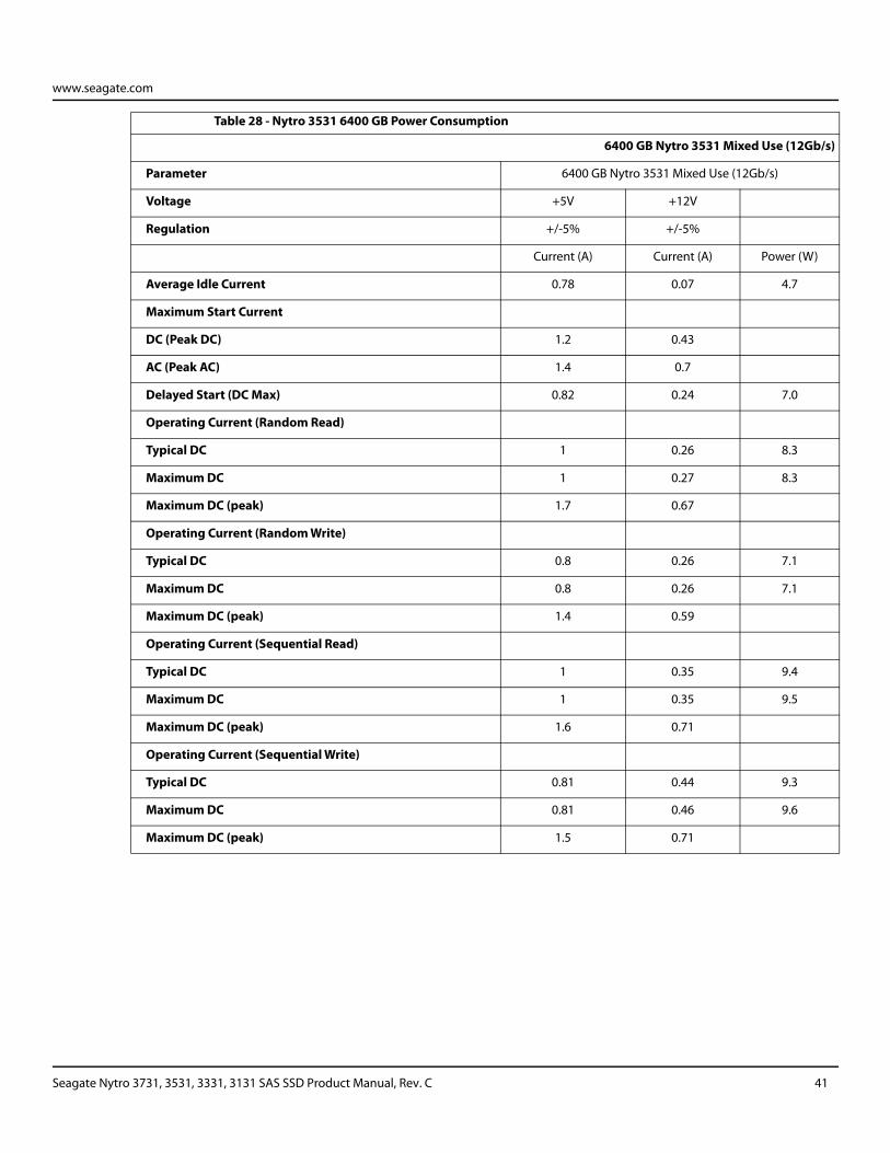
www.seagate.com
Table 28 - Nytro 3531 6400 GB Power Consumption
6400 GB Nytro 3531 Mixed Use (12Gb/s)
Parameter 6400 GB Nytro 3531 Mixed Use (12Gb/s)
Voltage +5V +12V
Regulation +/-5% +/-5%
Current (A) Current (A) Power (W)
Average Idle Current 0.78 0.07 4.7
Maximum Start Current
DC (Peak DC) 1.2 0.43
AC (Peak AC) 1.4 0.7
Delayed Start (DC Max) 0.82 0.24 7.0
Operating Current (Random Read)
Typical DC 1 0.26 8.3
Maximum DC 1 0.27 8.3
Maximum DC (peak) 1.7 0.67
Operating Current (Random Write)
Typical DC 0.8 0.26 7.1
Maximum DC 0.8 0.26 7.1
Maximum DC (peak) 1.4 0.59
Operating Current (Sequential Read)
Typical DC 1 0.35 9.4
Maximum DC 1 0.35 9.5
Maximum DC (peak) 1.6 0.71
Operating Current (Sequential Write)
Typical DC 0.81 0.44 9.3
Maximum DC 0.81 0.46 9.6
Maximum DC (peak) 1.5 0.71
Seagate Nytro 3731, 3531, 3331, 3131 SAS SSD Product Manual, Rev. C 41

www.seagate.com
Table 29 - Nytro 3331 960 GB Power Consumption
960 GB Nytro 3331 RI (12Gb/s)
Parameter 960 GB Nytro 3331 RI (12Gb/s)
Voltage +5V +12V
Regulation +/-5% +/-5%
Current (A) Current (A) Power (W)
Average Idle Current 0.74 0.06 4.5
Maximum Start Current
DC (Peak DC) 1.2 0.26
AC (Peak AC) 1.3 0.68
Delayed Start (DC Max) 0.81 0.29 7.5
Operating Current (Random Read)
Typical DC 0.91 0.17 6.6
Maximum DC 0.96 0.17 6.8
Maximum DC (peak) 1.4 0.52
Operating Current (Random Write)
Typical DC 0.79 0.22 6.5
Maximum DC 0.81 0.26 7.1
Maximum DC (peak) 1.3 0.56
Operating Current (Sequential Read)
Typical DC 0.99 0.25 8.0
Maximum DC 1.0 0.27 8.4
Maximum DC (peak) 1.6 0.65
Operating Current (Sequential Write)
Typical DC 0.78 0.25 6.9
Maximum DC 0.8 0.26 7.2
Maximum DC (peak) 1.4 0.58
Seagate Nytro 3731, 3531, 3331, 3131 SAS SSD Product Manual, Rev. C 42

www.seagate.com
Table 30 - Nytro 3331 1920 GB Power Consumption
1920 GB Nytro 3331 RI (12Gb/s)
Parameter 1920 GB Nytro 3331 RI (12Gb/s)
Voltage +5V +12V
Regulation +/-5% +/-5%
Current (A) Current (A) Power (W)
Average Idle Current 0.77 0.06 4.6
Maximum Start Current
DC (Peak DC) 1.2 0.33
AC (Peak AC) 1.3 0.64
Delayed Start (DC Max) 0.84 0.25 7.2
Operating Current (Random Read)
Typical DC 0.95 0.17 6.8
Maximum DC 1.0 0.17 7.1
Maximum DC (peak) 1.5 0.48
Operating Current (Random Write)
Typical DC 0.82 0.22 6.7
Maximum DC 0.87 0.26 7.5
Maximum DC (peak) 1.5 0.59
Operating Current (Sequential Read)
Typical DC 1.0 0.27 8.5
Maximum DC 1.1 0.28 8.8
Maximum DC (peak) 1.6 0.73
Operating Current (Sequential Write)
Typical DC 0.8 0.31 7.7
Maximum DC 0.83 0.33 8.1
Maximum DC (peak) 1.3 0.63
Seagate Nytro 3731, 3531, 3331, 3131 SAS SSD Product Manual, Rev. C 43

www.seagate.com
Table 31 - Nytro 3331 3840 GB Power Consumption
3840 GB Nytro 3331 RI (12Gb/s)
Parameter 3840 GB Nytro 3331 RI (12Gb/s)
Voltage +5V +12V
Regulation +/-5% +/-5%
Current (A) Current (A) Power (W)
Average Idle Current 0.76 0.06 4.6
Maximum Start Current
DC (Peak DC) 1.2 0.39
AC (Peak AC) 1.4 0.72
Delayed Start (DC Max) 0.8 0.23 6.8
Operating Current (Random Read)
Typical DC 0.97 0.21 7.3
Maximum DC 0.98 0.22 7.6
Maximum DC (peak) 1.6 0.65
Operating Current (Random Write)
Typical DC 0.84 0.27 7.4
Maximum DC 0.87 0.31 8.0
Maximum DC (peak) 1.5 0.68
Operating Current (Sequential Read)
Typical DC 1.0 0.29 8.6
Maximum DC 1.0 0.32 9.1
Maximum DC (peak) 1.6 0.73
Operating Current (Sequential Write)
Typical DC 0.83 0.34 8.2
Maximum DC 0.85 0.37 8.7
Maximum DC (peak) 1.6 0.73
Seagate Nytro 3731, 3531, 3331, 3131 SAS SSD Product Manual, Rev. C 44

www.seagate.com
Table 32 - Nytro 3331 7680 GB Power Consumption
7680 GB Nytro 3331 RI (12Gb/s)
Parameter 7680 GB Nytro 3331 RI (12Gb/s)
Voltage +5V +12V
Regulation +/-5% +/-5%
Current (A) Current (A) Power (W)
Average Idle Current 0.78 0.07 4.7
Maximum Start Current
DC (Peak DC) 1.2 0.43
AC (Peak AC) 1.4 0.7
Delayed Start (DC Max) 0.82 0.24 7.0
Operating Current (Random Read)
Typical DC 1.0 0.26 8.2
Maximum DC 1.0 0.27 8.3
Maximum DC (peak) 1.7 0.67
Operating Current (Random Write)
Typical DC 0.8 0.25 7.1
Maximum DC 0.8 0.26 7.1
Maximum DC (peak) 1.4 0.59
Operating Current (Sequential Read)
Typical DC 1.0 0.35 9.4
Maximum DC 1.0 0.35 9.5
Maximum DC (peak) 1.6 0.71
Operating Current (Sequential Write)
Typical DC 0.81 0.44 9.3
Maximum DC 0.81 0.46 9.6
Maximum DC (peak) 1.5 0.71
Seagate Nytro 3731, 3531, 3331, 3131 SAS SSD Product Manual, Rev. C 45

www.seagate.com
Table 33 - Nytro 3131 3840 GB Power Consumption
3840 GB Nytro 3131 VRI (12Gb/s)
Parameter 3840 GB Nytro 3131 VRI (12Gb/s)
Voltage +5V +12V
Regulation +/-5% +/-5%
Current (A) Current (A) Power (W)
Average Idle Current 0.74 0.05 4.3
Maximum Start Current
DC (Peak DC) 1.1 0.34
AC (Peak AC) 1.6 0.68
Delayed Start (DC Max) 0.79 0.2 6.3
Operating Current (Random Read)
Typical DC 0.82 0.12 5.5
Maximum DC 0.83 0.12 5.6
Maximum DC (peak) 1.1 0.36
Operating Current (Random Write)
Typical DC 0.75 0.17 5.8
Maximum DC 0.77 0.17 5.9
Maximum DC (peak) 0.88 0.57
Operating Current (Sequential Read)
Typical DC 0.88 0.15 6.2
Maximum DC 0.9 0.15 6.3
Maximum DC (peak) 1.3 0.39
Operating Current (Sequential Write)
Typical DC 0.77 0.39 8.5
Maximum DC 0.78 0.39 8.6
Maximum DC (peak) 0.92 0.84
Seagate Nytro 3731, 3531, 3331, 3131 SAS SSD Product Manual, Rev. C 46
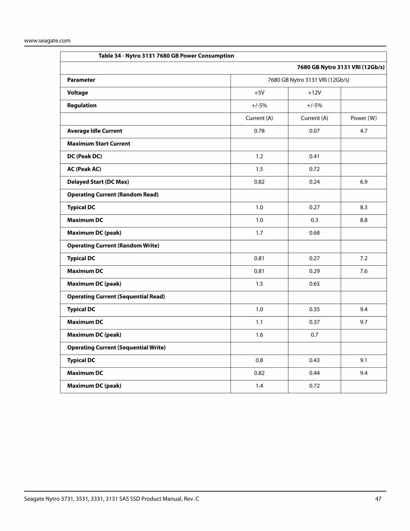
www.seagate.com
Table 34 - Nytro 3131 7680 GB Power Consumption
7680 GB Nytro 3131 VRI (12Gb/s)
Parameter 7680 GB Nytro 3131 VRI (12Gb/s)
Voltage +5V +12V
Regulation +/-5% +/-5%
Current (A) Current (A) Power (W)
Average Idle Current 0.78 0.07 4.7
Maximum Start Current
DC (Peak DC) 1.2 0.41
AC (Peak AC) 1.5 0.72
Delayed Start (DC Max) 0.82 0.24 6.9
Operating Current (Random Read)
Typical DC 1.0 0.27 8.3
Maximum DC 1.0 0.3 8.8
Maximum DC (peak) 1.7 0.68
Operating Current (Random Write)
Typical DC 0.81 0.27 7.2
Maximum DC 0.81 0.29 7.6
Maximum DC (peak) 1.5 0.65
Operating Current (Sequential Read)
Typical DC 1.0 0.35 9.4
Maximum DC 1.1 0.37 9.7
Maximum DC (peak) 1.6 0.7
Operating Current (Sequential Write)
Typical DC 0.8 0.43 9.1
Maximum DC 0.82 0.44 9.4
Maximum DC (peak) 1.4 0.72
Seagate Nytro 3731, 3531, 3331, 3131 SAS SSD Product Manual, Rev. C 47
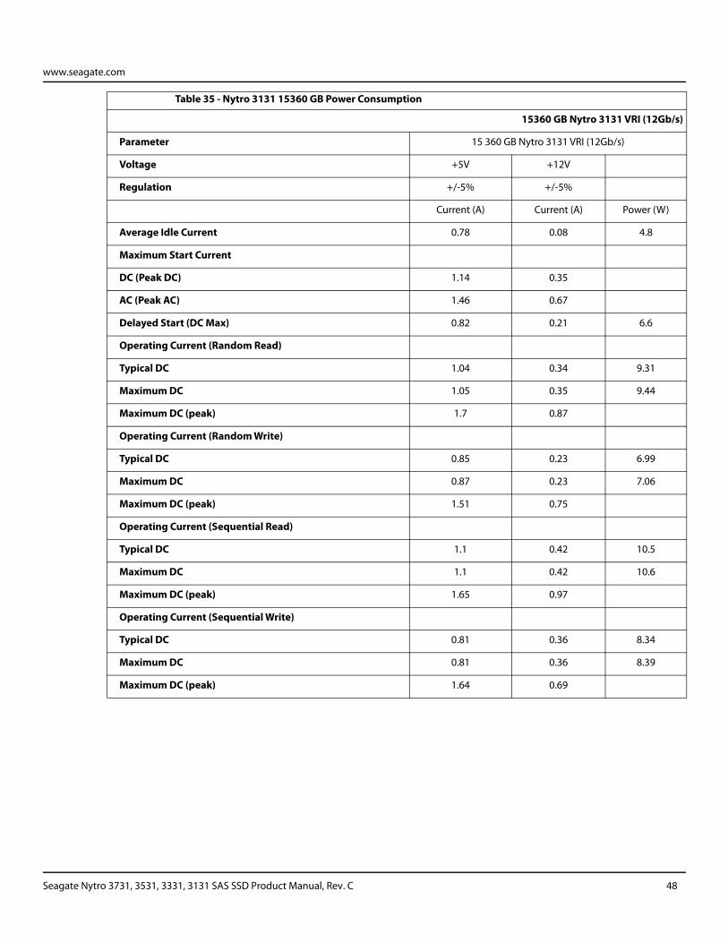
www.seagate.com
Table 35 - Nytro 3131 15360 GB Power Consumption
15360 GB Nytro 3131 VRI (12Gb/s)
Parameter 15 360 GB Nytro 3131 VRI (12Gb/s)
Voltage +5V +12V
Regulation +/-5% +/-5%
Current (A) Current (A) Power (W)
Average Idle Current 0.78 0.08 4.8
Maximum Start Current
DC (Peak DC) 1.14 0.35
AC (Peak AC) 1.46 0.67
Delayed Start (DC Max) 0.82 0.21 6.6
Operating Current (Random Read)
Typical DC 1.04 0.34 9.31
Maximum DC 1.05 0.35 9.44
Maximum DC (peak) 1.7 0.87
Operating Current (Random Write)
Typical DC 0.85 0.23 6.99
Maximum DC 0.87 0.23 7.06
Maximum DC (peak) 1.51 0.75
Operating Current (Sequential Read)
Typical DC 1.1 0.42 10.5
Maximum DC 1.1 0.42 10.6
Maximum DC (peak) 1.65 0.97
Operating Current (Sequential Write)
Typical DC 0.81 0.36 8.34
Maximum DC 0.81 0.36 8.39
Maximum DC (peak) 1.64 0.69
Seagate Nytro 3731, 3531, 3331, 3131 SAS SSD Product Manual, Rev. C 48
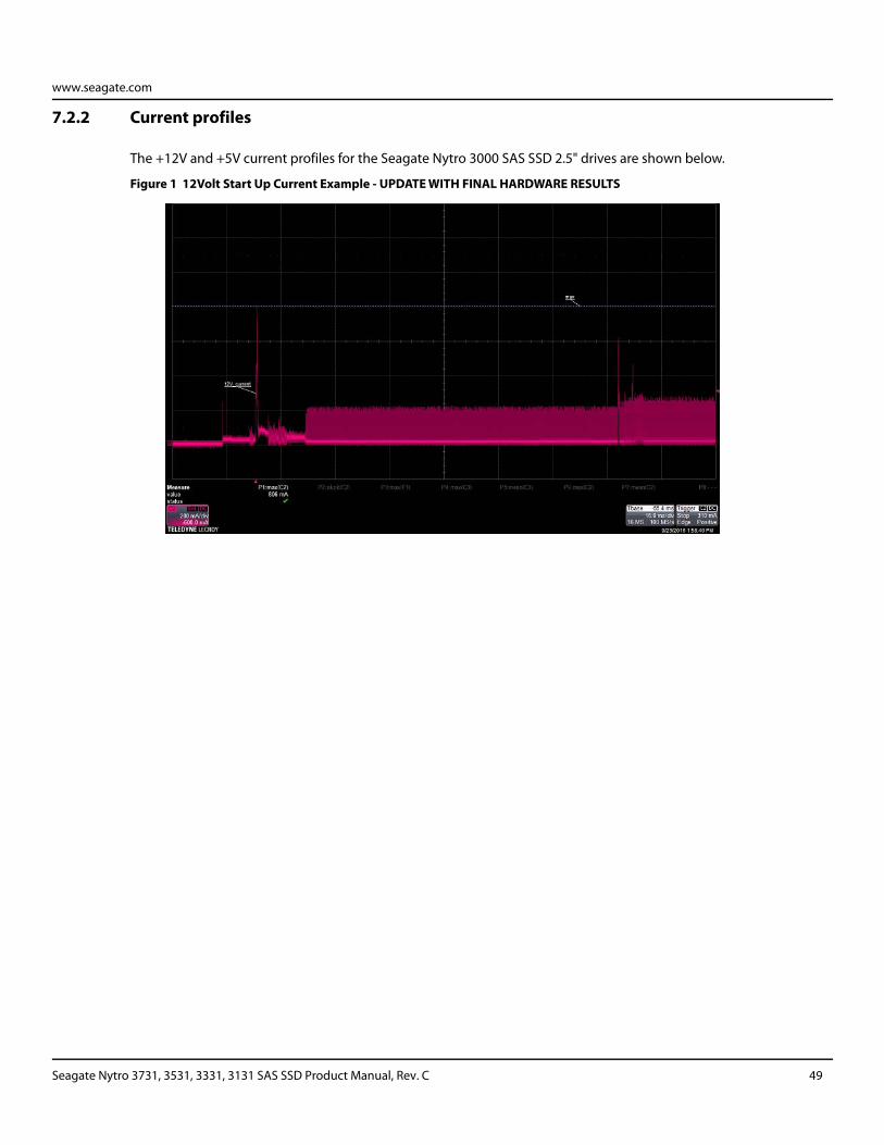
www.seagate.com
7.2.2 Current profiles
The +12V and +5V current profiles for the Seagate Nytro 3000 SAS SSD 2.5" drives are shown below.
Figure 1 12Volt Start Up Current Example - UPDATE WITH FINAL HARDWARE RESULTS
Seagate Nytro 3731, 3531, 3331, 3131 SAS SSD Product Manual, Rev. C 49
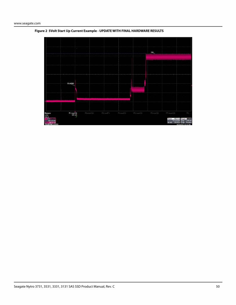
www.seagate.com
Figure 2 5Volt Start Up Current Example - UPDATE WITH FINAL HARDWARE RESULTS
Seagate Nytro 3731, 3531, 3331, 3131 SAS SSD Product Manual, Rev. C 50
www.seagate.com
7.3 Environmental limits
Temperature and humidity values experienced by the drive must be such that condensation does not occur on any drive part. Altitude and atmospheric pressure specifications are referenced to a standard day at 58.7°F (14.8°C). Maximum wet bulb temperature is 84.2°F (29°C).
NOTE To maintain optimal performance drives should be run at nominal case temperatures.
7.3.1 Temperature
7.3.1.1 Operating
The drive meets the operating specifications over a 32°F to 167°F (0°C to 70°C) drive internal temperature range with a maximum temperature gradient of 36°F (20°C) per hour.
NOTE Internal temperature swings greater than 55°C during over a 3 day time period may cause an elevated read error rate.
The maximum allowable drive internal temperature is 70°C. If the enclosure environment is unable to keep the internal temperature below this value the drive will reduce write activity to avoid over temperature condition. When the internal temperature is equal or greater than 65°C the drive will issue a SMART thermal warning.
The MTBF specification for the drive assumes the operating environment is designed to maintain nominal internal temperature. The rated MTBF is based upon a sustained internal temperature of 122°F (50°C). Occasional excursions in operating temperature between the rated MTBF temperature and the maximum drive operating internal temperature may occur without impact to the rated MTBF temperature. However continual or sustained operation at internal temperatures beyond the rated MTBF temperature will degrade the drive MTBF and reduce product reliability.
Air flow across the drive is expected under moderate to heavy write data workloads to stay under internal temperature limits described in this section. To confirm that the required cooling is provided, place the drive in its final mechanical configuration, and perform highest data throughput for the given application. If unknown writing large transfers sequentially on both port will consume the most current. After the temperatures stabilize, read the internal temperature of the drive using Seagate SeaChest or SeaTools utilities available at http://www.seagate.com.
7.3.1.2 Non-operating
-40° to 167°F (-40° to 75°C) package ambient with a maximum gradient of 36°F (20°C) per hour. This specification assumes that the drive is packaged in the shipping container designed by Seagate for use with drive.
7.3.2 Relative humidity
The values below assume that no condensation on the drive occurs.
Operating
5% to 95% non-condensing relative humidity with a maximum gradient of 20% per hour.
Non-operating
5% to 95% non-condensing relative humidity.
Seagate Nytro 3731, 3531, 3331, 3131 SAS SSD Product Manual, Rev. C 51
www.seagate.com
7.3.3 Effective altitude (sea level)
Operating
-1000 to +10,000 feet (-304.8 to +3048 meters)
Non-operating
-1000 to +40,000 feet (-304.8 to +12,192 meters)
7.3.4 Shock and vibration
Shock and vibration limits specified in this document are measured directly on the drive chassis. If the drive is installed in an enclosure to which the stated shock and/or vibration criteria is applied, resonances may occur internally to the enclosure resulting in drive movement in excess of the stated limits. If this situation is apparent, it may be necessary to modify the enclosure to minimize drive movement.
The limits of shock and vibration defined within this document are specified with the drive mounted by any of the four methods shown in Figure 8, Recommended mounting, on page 68, and in accordance with the restrictions the Section 11.3 Drive mounting, on page 68.
7.3.4.1 Shock
Operating - normal
The drive, as installed for normal operation, shall operate error free while subjected to intermittent shock not exceeding:
1000 Gs at a maximum duration of 0.5ms (half sinewave)
Shock may be applied in the X, Y, or Z axis. Shock is not to be repeated more than once every 2 seconds.
NOTE This specification does not cover connection issues that may result from testing at this level.
Non-operating
The limits of non-operating shock shall apply to all conditions of handling and transportation. This includes both isolated drives and integrated drives.
The drive subjected to non-repetitive shock not exceeding:
1000 Gs at a maximum duration of 0.5ms (half sinewave), shall not exhibit device damage or performance degradation.
Shock may be applied in the X, Y, or Z axis.
Packaged
Seagate finished drive bulk packs are designed and tested to meet or exceed applicable ISTA and ASTM standards. Volume finished drives will be shipped from Seagate factories on pallets to minimize freight costs and ease material handling. Seagate finished drive bulk packs may be shipped individually. For less than full shipments, instructions are printed on the bulk pack carton for minimum drive quantities and proper drive placement.
Seagate Nytro 3731, 3531, 3331, 3131 SAS SSD Product Manual, Rev. C 52
www.seagate.com
7.3.4.2 Vibration
Operating - normal
The drive s installed for normal operation, shall comply with the complete specified performance while subjected to vibration applied in the X, Y, or Z axis.
Operating normal translational random shaped profile: 20 - 2000 Hz, 11.08 GRMS
Operating - abnormal
Equipment as installed for normal operation shall not incur physical damage while subjected to periodic vibration:
Vibration occurring at these levels may degrade operational performance during the abnormal vibration period. Specified operational performance will continue when normal operating vibration levels are resumed. This assumes system recovery routines are available.
Operating abnormal translational random shaped profile: 20 - 2000 Hz, 11.08 GRMS
Non-operating
The limits of non-operating vibration shall apply to all conditions of handling and transportation. This includes both isolated drives and integrated drives.
The drive shall not incur physical damage or degraded performance as a result of vibration.
Vibration may be applied in the X, Y, or Z axis.
Non-operating translational random shaped profile: 20 - 2000 Hz, 11.08 GRMS
NOTE This specification does not cover connection issues that may result from testing at this level.
7.3.5 Air cleanliness
The drive is designed to operate in a typical office environment with minimal environmental control.
7.3.6 Corrosive environment
Seagate electronic drive components pass accelerated corrosion testing equivalent to 10 years exposure to light industrial environments containing sulfurous gases, chlorine and nitric oxide, classes G and H per ASTM B845. However, this accelerated testing cannot duplicate every potential application environment.
Users should use caution exposing any electronic components to uncontrolled chemical pollutants and corrosive chemicals as electronic drive component reliability can be affected by the installation environment. The silver, copper, nickel and gold films used in Seagate products are especially sensitive to the presence of sulfide, chloride, and nitrate contaminants. Sulfur is found to be the most damaging. Materials used in cabinet fabrication, such as vulcanized rubber, that can outgas corrosive compounds should be minimized or eliminated. The useful life of any electronic equipment may be extended by replacing materials near circuitry with sulfide-free alternatives.
Seagate recommends that data centers be kept clean by monitoring and controlling the dust and gaseous contamination. Gaseous contamination should be within ANSI/ISA S71.04-2013 G2 classification levels (as measured on copper and silver coupons), and dust contamination to ISO 14644-1 Class 8 standards, and MTBF rated conditions as defined in the Annualized Failure Rate (AFR) and Mean Time Between Failure (MTBF) section.
Seagate Nytro 3731, 3531, 3331, 3131 SAS SSD Product Manual, Rev. C 53
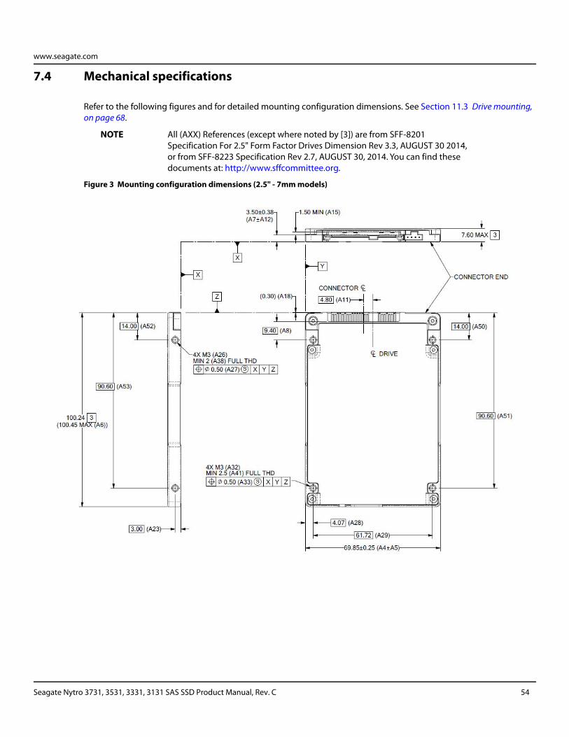
www.seagate.com
7.4 Mechanical specifications
Refer to the following figures and for detailed mounting configuration dimensions. See Section 11.3 Drive mounting, on page 68.
NOTE All (AXX) References (except where noted by [3]) are from SFF-8201 Specification For 2.5" Form Factor Drives Dimension Rev 3.3, AUGUST 30 2014, or from SFF-8223 Specification Rev 2.7, AUGUST 30, 2014. You can find these documents at: http://www.sffcommittee.org.
Figure 3 Mounting configuration dimensions (2.5" - 7mm models)
Seagate Nytro 3731, 3531, 3331, 3131 SAS SSD Product Manual, Rev. C 54
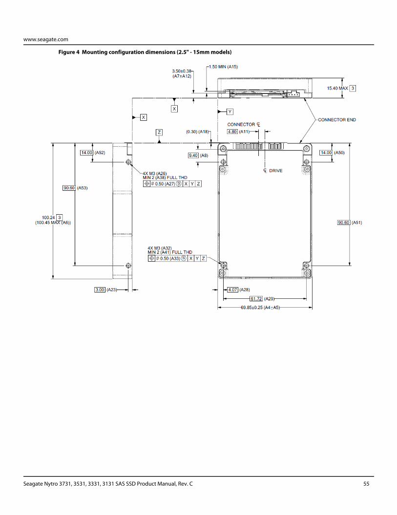
www.seagate.com
Figure 4 Mounting configuration dimensions (2.5" - 15mm models)
Seagate Nytro 3731, 3531, 3331, 3131 SAS SSD Product Manual, Rev. C 55
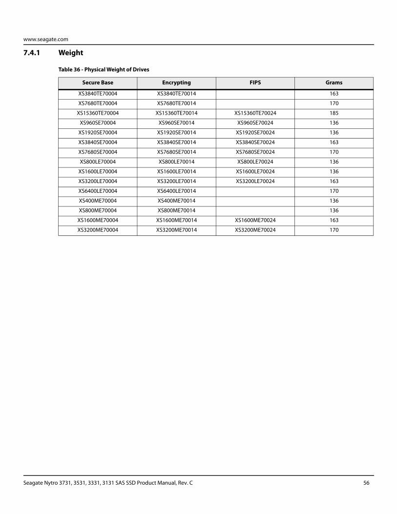
www.seagate.com
7.4.1 Weight
Table 36 - Physical Weight of Drives
Secure Base Encrypting FIPS Grams
XS3840TE70004 XS3840TE70014 163
XS7680TE70004 XS7680TE70014 170
XS15360TE70004 XS15360TE70014 XS15360TE70024 185
XS960SE70004 XS960SE70014 XS960SE70024 136
XS1920SE70004 XS1920SE70014 XS1920SE70024 136
XS3840SE70004 XS3840SE70014 XS3840SE70024 163
XS7680SE70004 XS7680SE70014 XS7680SE70024 170
XS800LE70004 XS800LE70014 XS800LE70024 136
XS1600LE70004 XS1600LE70014 XS1600LE70024 136
XS3200LE70004 XS3200LE70014 XS3200LE70024 163
XS6400LE70004 XS6400LE70014 170
XS400ME70004 XS400ME70014 136
XS800ME70004 XS800ME70014 136
XS1600ME70004 XS1600ME70014 XS1600ME70024 163
XS3200ME70004 XS3200ME70014 XS3200ME70024 170
Seagate Nytro 3731, 3531, 3331, 3131 SAS SSD Product Manual, Rev. C 56
www.seagate.com
8. About FIPS
The Federal Information Processing Standard (FIPS) Publication 140-2 is a U.S. Government Computer Security Standard used to accredit cryptographic modules. It is titled 'Security Requirements for Cryptographic Modules (FIPS PUB 140-2)' and is issued by the National Institute of Standards and Technology (NIST).
8.1 Purpose
This standard specifies the security requirements that will be satisfied by a cryptographic module utilized within a security system protecting sensitive but unclassified information. The standard provides four increasing, qualitative levels of security: Level 1, Level 2, Level 3 and Level 4. These levels are intended to cover the wide range of potential applications and environments in which cryptographic modules may be employed.
8.2 Validation Program
Products that claim conformance to this standard are validated by the Cryptographic Module Validation Program (CMVP) which is a joint effort between National Institute of Standards and Technology (NIST) and the Communications Security Establishment (CSE) of the Government of Canada. Products validated as conforming to FIPS 140-2 are accepted by the Federal agencies of both countries for the protection of sensitive information (United States) or Designated Information (Canada).
In the CMVP, vendors of cryptographic modules use independent, accredited testing laboratories to have their modules tested. National Voluntary Laboratory Accreditation Program (NVLAP) accredited laboratories perform cryptographic module compliance/conformance testing.
8.3 Seagate Enterprise SED
The SEDs referenced in this Product Manual have been validated by CMVP and have been thoroughly tested by a NVLAP accredited lab to satisfy FIPS 140-2 Level 2 requirements. In order to operate in FIPS Approved Mode of Operation, these SEDs require security initialization. For more information, refer to Security Rules section in the Security Policy document uploaded on the NIST website. To reference the product certification visit: http://csrc.nist.gov/groups/STM/cmvp/documents/140-1/1401vend.htm, and search for "Seagate".
Seagate Nytro 3731, 3531, 3331, 3131 SAS SSD Product Manual, Rev. C 57
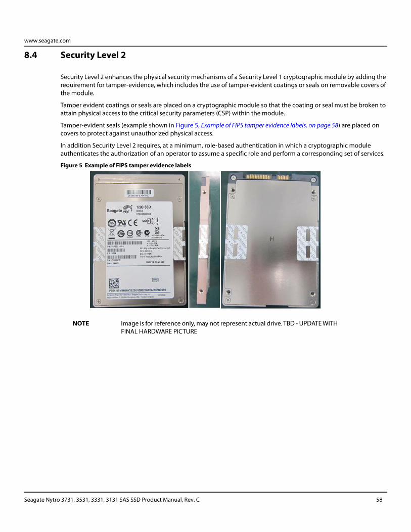
www.seagate.com
8.4 Security Level 2
Security Level 2 enhances the physical security mechanisms of a Security Level 1 cryptographic module by adding the requirement for tamper-evidence, which includes the use of tamper-evident coatings or seals on removable covers of the module.
Tamper evident coatings or seals are placed on a cryptographic module so that the coating or seal must be broken to attain physical access to the critical security parameters (CSP) within the module.
Tamper-evident seals (example shown in Figure 5, Example of FIPS tamper evidence labels, on page 58) are placed on covers to protect against unauthorized physical access.
In addition Security Level 2 requires, at a minimum, role-based authentication in which a cryptographic module authenticates the authorization of an operator to assume a specific role and perform a corresponding set of services.
Figure 5 Example of FIPS tamper evidence labels
NOTE Image is for reference only, may not represent actual drive. TBD - UPDATE WITH FINAL HARDWARE PICTURE
Seagate Nytro 3731, 3531, 3331, 3131 SAS SSD Product Manual, Rev. C 58
www.seagate.com
9. About self-encrypting drives
Self-encrypting drives (SEDs) offer encryption and security services for the protection of stored data, commonly known as protection of data at rest. These drives are compliant with the Trusted Computing Group (TCG) Enterprise Storage Specifications as detailed in Section.
The Trusted Computing Group (TCG) is an organization sponsored and operated by companies in the computer, storage and digital communications industry. The Seagate SED models comply with the standards published by the TCG.
To use the security features in the drive, the host must be capable of constructing and issuing the following two SCSI commands:
SECURITY PROTOCOL OUT
SECURITY PROTOCOL IN
These commands are used to convey the TCG protocol to and from the drive in the appropriate command payloads.
9.1 Data encryption
Encrypting drives use one in-line encryption engine for each port, employing AES-256 data encryption in Cipher Block Chaining (CBC) mode to encrypt all data prior to being written on the media and to decrypt all data as it is read from the media. The encryption engines are always in operation and cannot be disabled.
The 32-byte Data Encryption Key (DEK) is a random number which is generated by the drive, never leaves the drive, and is inaccessible to the host system. The DEK is itself encrypted when it is stored on the media and when it is in volatile temporary storage (DRAM) external to the encryption engine. A unique data encryption key is used for each of the drive's possible 16 data bands (see Section 9.5 Data bands, on page 60).
9.2 Controlled access
The drive has two security providers (SPs) called the "Admin SP" and the "Locking SP." These act as gatekeepers to the drive security services. Security-related commands will not be accepted unless they also supply the correct credentials to prove the requester is authorized to perform the command.
9.2.1 Admin SP
The Admin SP allows the drive's owner to enable or disable firmware download operations (see Section 6.4). Access to the Admin SP is available using the SID (Secure ID) password or the MSID (Manufacturers Secure ID) password.
9.2.2 Locking SP
The Locking SP controls read/write access to the media and the cryptographic erase feature. Access to the Locking SP is available using the BandMasterX or EraseMaster passwords. Since the drive owner can define up to 16 data bands on the drive, each data band has its own password called BandMasterX where X is the number of the data band (0 through 15).
Seagate Nytro 3731, 3531, 3331, 3131 SAS SSD Product Manual, Rev. C 59
www.seagate.com
9.2.3 Default password
When the drive is shipped from the factory, all passwords are set to the value of MSID. This 32-byte random value can only be read by the host electronically over the interface. After receipt of the drive, it is the responsibility of the owner to use the default MSID password as the authority to change all other passwords to unique owner-specified values.
9.3 Random number generator (RNG)
The drive has a 32-byte hardware RNG that it is uses to derive encryption keys or, if requested to do so, to provide random numbers to the host for system use, including using these numbers as Authentication Keys (passwords) for the drive's Admin and Locking SPs.
9.4 Drive locking
In addition to changing the passwords, as described in Section 9.2.3 Default password, on page 60, the owner should also set the data access controls for the individual bands.
The variable LockOnReset should be set to PowerCycle to ensure that the data bands will be locked if power is lost. In addition ReadLockEnabled and WriteLockEnabled must be set to true in the locking table in order for the bands LockOnReset setting of PowerCycle to actually lock access to the band when a PowerCycle event occurs. This scenario occurs if the drive is removed from its cabinet. The drive will not honor any data READ or WRITE requests until the bands have been unlocked. This prevents the user data from being accessed without the appropriate credentials when the drive has been removed from its cabinet and installed in another system.
When the drive is shipped from the factory, the firmware download port is unlocked allowing the drive to accept any attempt to download new firmware. The drive owner must use the SID credential to lock the firmware download port before firmware updates will be rejected.
9.5 Data bands
When shipped from the factory, the drive is configured with a single data band called Band 0 (also known as the Global Data Band) which comprises LBA 0 through LBA max. The host may allocate Band1 by specifying a start LBA and an LBA range. The real estate for this band is taken from the Global Band. An additional 14 Data Bands may be defined in a similar way (Band2 through Band15) but before these bands can be allocated LBA space, they must first be individually enabled using the EraseMaster password.
Data bands cannot overlap but they can be sequential with one band ending at LBA (x) and the next beginning at LBA (x+1).
Each data band has its own drive-generated encryption key and its own user-supplied password. The host may change the Encryption Key or the password when required. The bands shall be aligned to 4KB LBA boundaries.
Seagate Nytro 3731, 3531, 3331, 3131 SAS SSD Product Manual, Rev. C 60
www.seagate.com
9.6 Cryptographic erase
A significant feature of SEDs is the ability to perform a cryptographic erase. This involves the host telling the drive to change the data encryption key for a particular band. Once changed, the data is no longer recoverable since it was written with one key and will be read using a different key. Since the drive overwrites the old key with the new one, and keeps no history of key changes, the user data can never be recovered. This is tantamount to an instantaneous data erase and is very useful if the drive is to be scrapped or redispositioned. Erased sectors will be unmapped and return all zeros if read.
9.7 Authenticated firmware download
In addition to providing a locking mechanism to prevent unwanted firmware download attempts, the drive also only accepts download files which have been cryptographically signed by the appropriate Seagate Design Center.
Three conditions must be met before the drive will allow the download operation:
1. The download must be an SED file. A standard (base) drive (non-SED) file will be rejected.
2. The download file must be digitally signed and authenticated.
3. As with a non-SED drive, the download file must pass the acceptance criteria for the drive. For example it must be applicable to the correct drive model, and have compatible revision and customer status.
9.8 Power requirements
The standard drive models and the SED drive models have identical hardware, however the security and encryption portion of the drive controller ASIC is enabled and functional in the SED models. This represents a small additional drain on the 5V supply of about 30mA and a commensurate increase of about 150mW in power consumption. There is no additional drain on the 12V supply. See the tables in Section 7.2 Power consumption, on page 33 for power requirements on the standard (non-SED) drive models.
Seagate Nytro 3731, 3531, 3331, 3131 SAS SSD Product Manual, Rev. C 61
www.seagate.com
9.9 Supported commands
The SED models support the following two commands in addition to the commands supported by the standard (non-SED) models as listed in Table 40, Supported commands, on page 70.
SECURITY PROTOCOL OUT (B5h)
SECURITY PROTOCOL IN (A2h)
9.10 Sanitize - Cryptographic Erase
This command cryptographically erases all user data on the drive by destroying the current data encryption key and replacing it with a new data encryption key randomly generated by the drive. Sanitize CRYPTOGRAPHIC ERASE is a SCSI CDB Op code 48h and selecting the service action code 3 (CRYPTOGRAPHIC ERASE).
9.11 RevertSP
SED models will support the RevertSP feature which erases all data in all bands on the device and returns the contents of all SPs (Security Providers) on the device to their original factory state. In order to execute the RevertSP method the unique PSID (Physical Secure ID) printed on the drive label must be provided. PSID is not electronically accessible and can only be manually read from the drive label or scanned in via the 2D barcode.
Seagate Nytro 3731, 3531, 3331, 3131 SAS SSD Product Manual, Rev. C 62
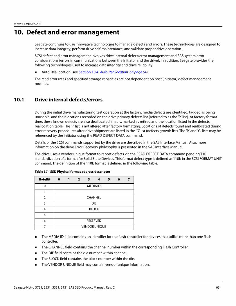
www.seagate.com
10. Defect and error management
Seagate continues to use innovative technologies to manage defects and errors. These technologies are designed to increase data integrity, perform drive self-maintenance, and validate proper drive operation.
SCSI defect and error management involves drive internal defect/error management and SAS system error considerations (errors in communications between the initiator and the drive). In addition, Seagate provides the following technologies used to increase data integrity and drive reliability:
Auto-Reallocation (see Section 10.4 Auto-Reallocation, on page 64)
The read error rates and specified storage capacities are not dependent on host (initiator) defect management routines.
10.1 Drive internal defects/errors
During the initial drive manufacturing test operation at the factory, media defects are identified, tagged as being unusable, and their locations recorded on the drive primary defects list (referred to as the 'P' list). At factory format time, these known defects are also deallocated, that is, marked as retired and the location listed in the defects reallocation table. The 'P' list is not altered after factory formatting. Locations of defects found and reallocated during error recovery procedures after drive shipment are listed in the 'G' list (defects growth list). The 'P' and 'G' lists may be referenced by the initiator using the READ DEFECT DATA command.
Details of the SCSI commands supported by the drive are described in the SAS Interface Manual. Also, more information on the drive Error Recovery philosophy is presented in the SAS Interface Manual.
The drive uses a vendor unique format to report defects via the READ DEFECT DATA command pending T10 standardization of a format for Solid State Devices. This format defect type is defined as 110b in the SCSI FORMAT UNIT command. The definition of the 110b format is defined in the following table.
The MEDIA ID field contains an identifier for the flash controller for devices that utilize more than one flash controller.
The CHANNEL field contains the channel number within the corresponding Flash Controller.
The DIE field contains the die number within channel.
The BLOCK field contains the block number within the die.
The VENDOR UNIQUE field may contain vendor unique information.
Table 37 - SSD Physical format address descriptor
ByteBit 0 1 2 3 4 5 6 7
0 MEDIA ID
1
2 CHANNEL
3 DIE
4 BLOCK
5
6 RESERVED
7 VENDOR UNIQUE
Seagate Nytro 3731, 3531, 3331, 3131 SAS SSD Product Manual, Rev. C 63
www.seagate.com
10.2 Drive error recovery procedures
When an error occurs during drive operation, the drive performs error recovery procedures to attempt to recover the data. The error recovery procedures used are not user changeable.
10.3 SAS system errors
Information on the reporting of operational errors across the interface is given in the SAS Interface Manual. The SSP Response returns information to the host about numerous kinds of errors. The Receive Diagnostic Results reports the results of diagnostic operations performed by the drive.
Status returned by the drive to the initiator is described in the SAS Interface Manual. Status reporting plays a role in systems error management and its use in that respect is described in sections where the various commands are discussed.
10.4 Auto-Reallocation
Auto-Reallocation allows the drive to reallocate unreadable locations on a subsequent write command if the recovery process deems the location to be defective. The drive performs auto-reallocation on every WRITE command. With each write to a Logical LBA, the drive writes the data to a different physical media location. Physical locations that return unrecoverable errors are retired during future WRITE attempts and associated recovery process.
This is in contrast to the system having to use the REASSIGN BLOCKS command to reassign a location that was unreadable and then generate a WRITE command to rewrite the data. This operation requires that AWRE and ARRE are enabled which is the default setting from the Seagate factory.
10.5 Protection Information (PI)
Protection Information is intended as a standardized approach to system level LRC traditionally provided by systems using 520 byte formatted LBAs.
Drives formatted with PI information provide the same, common LBA count (i.e. same capacity point) as non- PI formatted drives.
Sequential performance of a PI drive will be reduced by approximately 1.56% due to the extra overhead of PI being transferred from the media that is not calculated as part of the data transferred to the host.
To determine the full transfer rate of a PI drive, transfers should be calculated by adding the 8 extra bytes of PI to the transferred LBA length, i.e. 512 + 8 = 520.
PI formatted drives are physically formatted to 520 byte LBAs that store 512 bytes of customer data with 8 bytes of Protection Information appended to it.
The advantage of PI is that the Protection Information bits can be managed at the HBA and HBA driver level.
Allowing a system that typically does not support 520 LBA formats to integrate this level of protection.
Protection Information is valid with any supported LBA size, except 528.
512 LBA size is used here as common example.
Seagate Nytro 3731, 3531, 3331, 3131 SAS SSD Product Manual, Rev. C 64
www.seagate.com
10.5.1 Levels of PI
There are 4 types of Protection Information.
Type 0 - Describes a drive that is not formatted with PI information bytes. This allows for legacy support in non-PI systems.
Type 1 - Provides support of PI protection using 10 and 16 byte commands. The RDPROTECT and WRTPROTECT bits allow for checking control through the CDB. Eight bytes of Protection Information are transmitted at LBA boundaries across the interface if RDPROTECT and WRTPROTECT bits are nonzero values. Type 1 does not allow the use of 32 byte commands.
Type 2 - Provides checking control and additional expected fields within the 32 byte CDBs. Eight bytes of Protection Information are transmitted at LBA boundaries across the interface if RDPROTECT and WRTPROTECT bits are nonzero values. Type 2 does allow the use of 10 and 16 byte commands with zero values in the RDPROTECT and WRTPROTECT fields. The drive will generate 8 bytes of Protection Information (e.g. 0xFFFFFFFF) to be stored on the media, but the 8 bytes will not be transferred to the host during a READ command.
Type 3 - Seagate products do not support Type 3.
10.5.2 Setting and determining the current Type Level
A drive is initialized to a type of PI by using the FORMAT UNIT command on a PI capable drive. Once a drive is formatted to a PI Type, it may be queried by a READ CAPACITY (16) command to report the PI type which it is currently formatted to. A drive can only be formatted to a single PI Type. It can be changed at anytime to a new Type but requires a FORMAT UNIT command which destroys all existing data on the drive. No other vehicle for changing the PI type is provided by the T10 SBC3 specification.
Type 1 PI FORMAT UNIT CDB command: 04 90 00 00 00 00, parameter data: 00 A0 00 00
Type 2 PI FORMAT UNIT CDB command: 04 D0 00 00 00 00, parameter data: 00 A0 00 00
10.5.3 Identifying a Protection Information drive
The Standard INQUIRY data provides a bit to indicate if PI is support by the drive. Vital Product Descriptor (VPD) page 0x86 provides bits to indicate the PI Types supported and which PI fields the drive supports checking.
NOTE For further details with respect to PI, please refer to SCSI Block Commands - 4 (SBC-4) Draft Standard documentation.
Seagate Nytro 3731, 3531, 3331, 3131 SAS SSD Product Manual, Rev. C 65
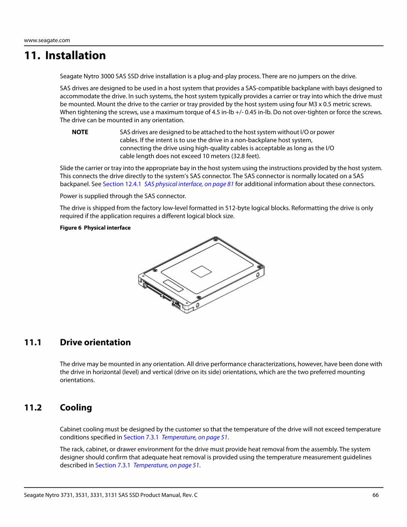
www.seagate.com
11. Installation
Seagate Nytro 3000 SAS SSD drive installation is a plug-and-play process. There are no jumpers on the drive.
SAS drives are designed to be used in a host system that provides a SAS-compatible backplane with bays designed to accommodate the drive. In such systems, the host system typically provides a carrier or tray into which the drive must be mounted. Mount the drive to the carrier or tray provided by the host system using four M3 x 0.5 metric screws. When tightening the screws, use a maximum torque of 4.5 in-lb +/- 0.45 in-lb. Do not over-tighten or force the screws. The drive can be mounted in any orientation.
NOTE SAS drives are designed to be attached to the host system without I/O or power cables. If the intent is to use the drive in a non-backplane host system, connecting the drive using high-quality cables is acceptable as long as the I/O cable length does not exceed 10 meters (32.8 feet).
Slide the carrier or tray into the appropriate bay in the host system using the instructions provided by the host system. This connects the drive directly to the system’s SAS connector. The SAS connector is normally located on a SAS backpanel. See Section 12.4.1 SAS physical interface, on page 81 for additional information about these connectors.
Power is supplied through the SAS connector.
The drive is shipped from the factory low-level formatted in 512-byte logical blocks. Reformatting the drive is only required if the application requires a different logical block size.
Figure 6 Physical interface
11.1 Drive orientation
The drive may be mounted in any orientation. All drive performance characterizations, however, have been done with the drive in horizontal (level) and vertical (drive on its side) orientations, which are the two preferred mounting orientations.
11.2 Cooling
Cabinet cooling must be designed by the customer so that the temperature of the drive will not exceed temperature conditions specified in Section 7.3.1 Temperature, on page 51.
The rack, cabinet, or drawer environment for the drive must provide heat removal from the assembly. The system designer should confirm that adequate heat removal is provided using the temperature measurement guidelines described in Section 7.3.1 Temperature, on page 51.
Seagate Nytro 3731, 3531, 3331, 3131 SAS SSD Product Manual, Rev. C 66
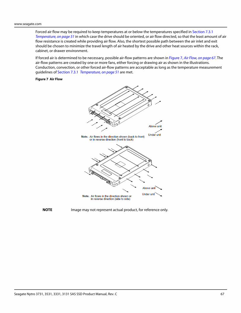
www.seagate.com
Forced air flow may be required to keep temperatures at or below the temperatures specified in Section 7.3.1 Temperature, on page 51 in which case the drive should be oriented, or air flow directed, so that the least amount of air flow resistance is created while providing air flow. Also, the shortest possible path between the air inlet and exit should be chosen to minimize the travel length of air heated by the drive and other heat sources within the rack, cabinet, or drawer environment.
If forced air is determined to be necessary, possible air-flow patterns are shown in Figure 7, Air Flow, on page 67. The air-flow patterns are created by one or more fans, either forcing or drawing air as shown in the illustrations. Conduction, convection, or other forced air-flow patterns are acceptable as long as the temperature measurement guidelines of Section 7.3.1 Temperature, on page 51 are met.
Figure 7 Air Flow
NOTE Image may not represent actual product, for reference only.
Seagate Nytro 3731, 3531, 3331, 3131 SAS SSD Product Manual, Rev. C 67
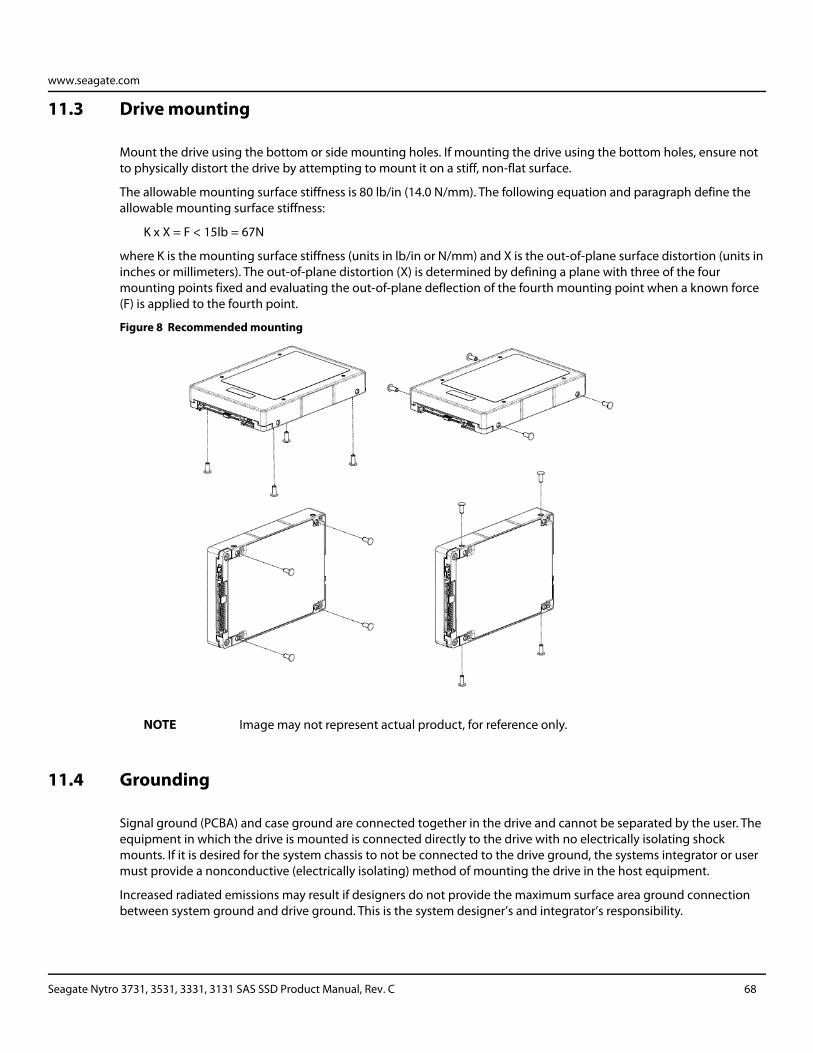
www.seagate.com
11.3 Drive mounting
Mount the drive using the bottom or side mounting holes. If mounting the drive using the bottom holes, ensure not to physically distort the drive by attempting to mount it on a stiff, non-flat surface.
The allowable mounting surface stiffness is 80 lb/in (14.0 N/mm). The following equation and paragraph define the allowable mounting surface stiffness:
K x X = F < 15lb = 67N
where K is the mounting surface stiffness (units in lb/in or N/mm) and X is the out-of-plane surface distortion (units in inches or millimeters). The out-of-plane distortion (X) is determined by defining a plane with three of the four mounting points fixed and evaluating the out-of-plane deflection of the fourth mounting point when a known force (F) is applied to the fourth point.
Figure 8 Recommended mounting
NOTE Image may not represent actual product, for reference only.
11.4 Grounding
Signal ground (PCBA) and case ground are connected together in the drive and cannot be separated by the user. The equipment in which the drive is mounted is connected directly to the drive with no electrically isolating shock mounts. If it is desired for the system chassis to not be connected to the drive ground, the systems integrator or user must provide a nonconductive (electrically isolating) method of mounting the drive in the host equipment.
Increased radiated emissions may result if designers do not provide the maximum surface area ground connection between system ground and drive ground. This is the system designer’s and integrator’s responsibility.
Seagate Nytro 3731, 3531, 3331, 3131 SAS SSD Product Manual, Rev. C 68
www.seagate.com
12. Interface requirements
This section partially describes the interface requirements as implemented on Seagate Nytro 3000 SAS SSD drives. Additional information is provided in the SAS Interface Manual (part number 100293071).
12.1 SAS features
This section lists the SAS-specific features supported by Seagate Nytro 3000 SAS SSD drives.
12.1.1 Task management functions
The following table lists the SAS task management functions supported by Seagate Nytro 3000 SAS SSD drives.
12.1.2 Task management responses
The following table lists the SAS response codes returned for task management functions supported.
Table 38 - SAS task management functions supported
Task name Supported
Abort Task Yes
Abort task set Yes
Clear ACA Yes
Clear task set Yes
I_T Nexus Reset Yes
Logical Unit Reset Yes
Query Task Yes
Query Task Set Yes
Query Asynchronous Event Yes
Table 39 - Task management response codes
Function name Response code
Function complete 00
Invalid frame 02
Function not supported 04
Function failed 05
Function succeeded 08
Invalid logical unit 09
Seagate Nytro 3731, 3531, 3331, 3131 SAS SSD Product Manual, Rev. C 69
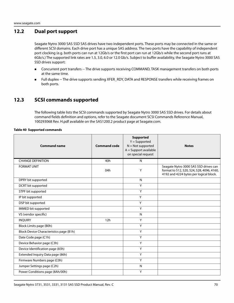
www.seagate.com
12.2 Dual port support
Seagate Nytro 3000 SAS SSD SAS drives have two independent ports. These ports may be connected in the same or different SCSI domains. Each drive port has a unique SAS address. The two ports have the capability of independent port clocking (e.g. both ports can run at 12Gb/s or the first port can run at 12Gb/s while the second port runs at 6Gb/s.) The supported link rates are 1.5, 3.0, 6.0 or 12.0 Gb/s. Subject to buffer availability, the Seagate Nytro 3000 SAS SSD drives support:
Concurrent port transfers -- The drive supports receiving COMMAND, TASK management transfers on both ports at the same time.
Full duplex -- The drive supports sending XFER_RDY, DATA and RESPONSE transfers while receiving frames on both ports.
12.3 SCSI commands supported
The following table lists the SCSI commands supported by Seagate Nytro 3000 SAS SSD drives. For details about command fields definition and options, refer to the Seagate document SCSI Commands Reference Manual, 100293068 Rev. H.pdf available on the SAS1200.2 product page at Seagate.com.
Table 40 Supported commands
Command name Command code
SupportedY = Supported
N = Not supported A = Support available
on special request
Notes
CHANGE DEFINITION 40h N
FORMAT UNIT 04h Y
Seagate Nytro 3000 SAS SSD drives can format to 512, 520, 524, 528, 4096, 4160, 4192 and 4224 bytes per logical block.
DPRY bit supported N
DCRT bit supported Y
STPF bit supported Y
IP bit supported Y
DSP bit supported Y
IMMED bit supported Y
VS (vendor specific) N
INQUIRY 12h Y
Block Limits page (B0h) Y
Block Device Characteristics page (B1h) Y
Date Code page (C1h) Y
Device Behavior page (C3h) Y
Device Identification page (83h) Y
Extended Inquiry Data page (86h) Y
Firmware Numbers page (C0h) Y
Jumper Settings page (C2h) N
Power Conditions page (8Ah/00h) Y
Seagate Nytro 3731, 3531, 3331, 3131 SAS SSD Product Manual, Rev. C 70
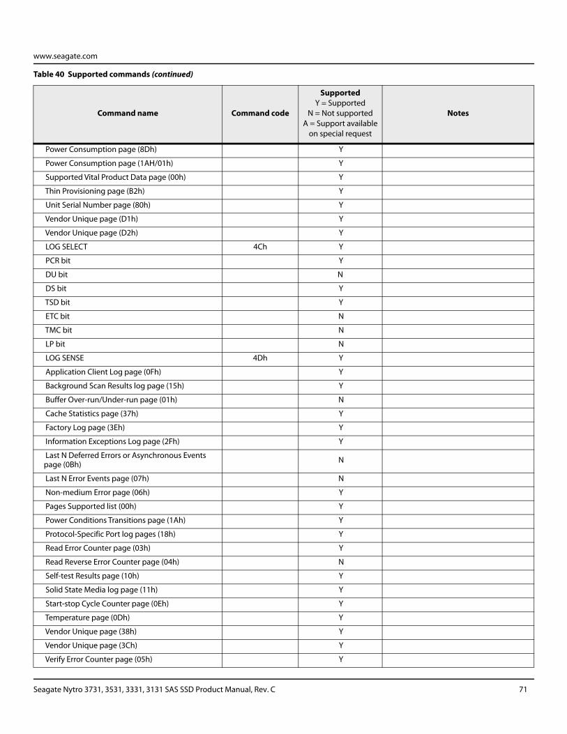
www.seagate.com
Power Consumption page (8Dh) Y
Power Consumption page (1AH/01h) Y
Supported Vital Product Data page (00h) Y
Thin Provisioning page (B2h) Y
Unit Serial Number page (80h) Y
Vendor Unique page (D1h) Y
Vendor Unique page (D2h) Y
LOG SELECT 4Ch Y
PCR bit Y
DU bit N
DS bit Y
TSD bit Y
ETC bit N
TMC bit N
LP bit N
LOG SENSE 4Dh Y
Application Client Log page (0Fh) Y
Background Scan Results log page (15h) Y
Buffer Over-run/Under-run page (01h) N
Cache Statistics page (37h) Y
Factory Log page (3Eh) Y
Information Exceptions Log page (2Fh) Y
Last N Deferred Errors or Asynchronous Events page (0Bh) N
Last N Error Events page (07h) N
Non-medium Error page (06h) Y
Pages Supported list (00h) Y
Power Conditions Transitions page (1Ah) Y
Protocol-Specific Port log pages (18h) Y
Read Error Counter page (03h) Y
Read Reverse Error Counter page (04h) N
Self-test Results page (10h) Y
Solid State Media log page (11h) Y
Start-stop Cycle Counter page (0Eh) Y
Temperature page (0Dh) Y
Vendor Unique page (38h) Y
Vendor Unique page (3Ch) Y
Verify Error Counter page (05h) Y
Table 40 Supported commands (continued)
Command name Command code
SupportedY = Supported
N = Not supported A = Support available
on special request
Notes
Seagate Nytro 3731, 3531, 3331, 3131 SAS SSD Product Manual, Rev. C 71
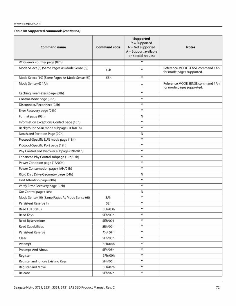
www.seagate.com
Write error counter page (02h) Y
Mode Select (6) (Same Pages As Mode Sense (6)) 15h Y Reference MODE SENSE command 1Ah for mode pages supported.
Mode Select (10) (Same Pages As Mode Sense (6)) 55h Y
Mode Sense (6) 1Ah Y Reference MODE SENSE command 1Ah for mode pages supported.
Caching Parameters page (08h) Y
Control Mode page (0Ah) Y
Disconnect/Reconnect (02h) Y
Error Recovery page (01h) Y
Format page (03h) N
Information Exceptions Control page (1Ch) Y
Background Scan mode subpage (1Ch/01h) Y
Notch and Partition Page (0Ch) N
Protocol-Specific LUN mode page (18h) Y
Protocol-Specific Port page (19h) Y
Phy Control and Discover subpage (19h/01h) Y
Enhanced Phy Control subpage (19h/03h) Y
Power Condition page (1A/00h) Y
Power Consumption page (1AH/01h) Y
Rigid Disc Drive Geometry page (04h) N
Unit Attention page (00h) Y
Verify Error Recovery page (07h) Y
Xor Control page (10h) N
Mode Sense (10) (Same Pages As Mode Sense (6)) 5Ah Y
Persistent Reserve In 5Eh Y
Read Full Status 5Eh/03h Y
Read Keys 5Eh/00h Y
Read Reservations 5Eh/001 Y
Read Capabilities 5Eh/02h Y
Persistent Reserve Out 5Fh Y
Clear 5Fh/03h Y
Preempt 5Fh/04h Y
Preempt And About 5Fh/05h Y
Register 5Fh/00h Y
Register and Ignore Existing Keys 5Fh/06h Y
Register and Move 5Fh/07h Y
Release 5Fh/02h Y
Table 40 Supported commands (continued)
Command name Command code
SupportedY = Supported
N = Not supported A = Support available
on special request
Notes
Seagate Nytro 3731, 3531, 3331, 3131 SAS SSD Product Manual, Rev. C 72
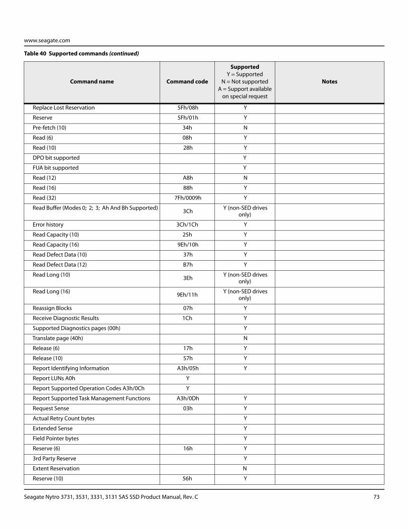
www.seagate.com
Replace Lost Reservation 5Fh/08h Y
Reserve 5Fh/01h Y
Pre-fetch (10) 34h N
Read (6) 08h Y
Read (10) 28h Y
DPO bit supported Y
FUA bit supported Y
Read (12) A8h N
Read (16) 88h Y
Read (32) 7Fh/0009h Y
Read Buffer (Modes 0; 2; 3; Ah And Bh Supported) 3Ch Y (non-SED drives only)
Error history 3Ch/1Ch Y
Read Capacity (10) 25h Y
Read Capacity (16) 9Eh/10h Y
Read Defect Data (10) 37h Y
Read Defect Data (12) B7h Y
Read Long (10) 3Eh Y (non-SED drives only)
Read Long (16) 9Eh/11h Y (non-SED drives only)
Reassign Blocks 07h Y
Receive Diagnostic Results 1Ch Y
Supported Diagnostics pages (00h) Y
Translate page (40h) N
Release (6) 17h Y
Release (10) 57h Y
Report Identifying Information A3h/05h Y
Report LUNs A0h Y
Report Supported Operation Codes A3h/0Ch Y
Report Supported Task Management Functions A3h/0Dh Y
Request Sense 03h Y
Actual Retry Count bytes Y
Extended Sense Y
Field Pointer bytes Y
Reserve (6) 16h Y
3rd Party Reserve Y
Extent Reservation N
Reserve (10) 56h Y
Table 40 Supported commands (continued)
Command name Command code
SupportedY = Supported
N = Not supported A = Support available
on special request
Notes
Seagate Nytro 3731, 3531, 3331, 3131 SAS SSD Product Manual, Rev. C 73
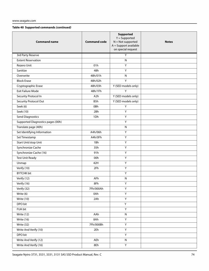
www.seagate.com
3rd Party Reserve Y
Extent Reservation N
Rezero Unit 01h Y
Sanitize 48h Y
Overwrite 48h/01h N
Block Erase 48h/02h Y
Cryptographic Erase 48h/03h Y (SED models only)
Exit Failure Mode 48h/1Fh Y
Security Protocol In A2h Y (SED models only)
Security Protocol Out B5h Y (SED models only)
Seek (6) 0Bh Y
Seek (10) 2Bh Y
Send Diagnostics 1Dh Y
Supported Diagnostics pages (00h) Y
Translate page (40h) N
Set Identifying Information A4h/06h Y
Set Timestamp A4h/0Fh Y
Start Unit/stop Unit 1Bh Y
Synchronize Cache 35h Y
Synchronize Cache (16) 91h Y
Test Unit Ready 00h Y
Unmap 42H Y
Verify (10) 2Fh Y
BYTCHK bit Y
Verify (12) AFh N
Verify (16) 8Fh Y
Verify (32) 7Fh/000Ah Y
Write (6) 0Ah Y
Write (10) 2Ah Y
DPO bit Y
FUA bit Y
Write (12) AAh N
Write (16) 8Ah Y
Write (32) 7Fh/000Bh Y
Write And Verify (10) 2Eh Y
DPO bit Y
Write And Verify (12) AEh N
Write And Verify (16) 8Eh Y
Table 40 Supported commands (continued)
Command name Command code
SupportedY = Supported
N = Not supported A = Support available
on special request
Notes
Seagate Nytro 3731, 3531, 3331, 3131 SAS SSD Product Manual, Rev. C 74
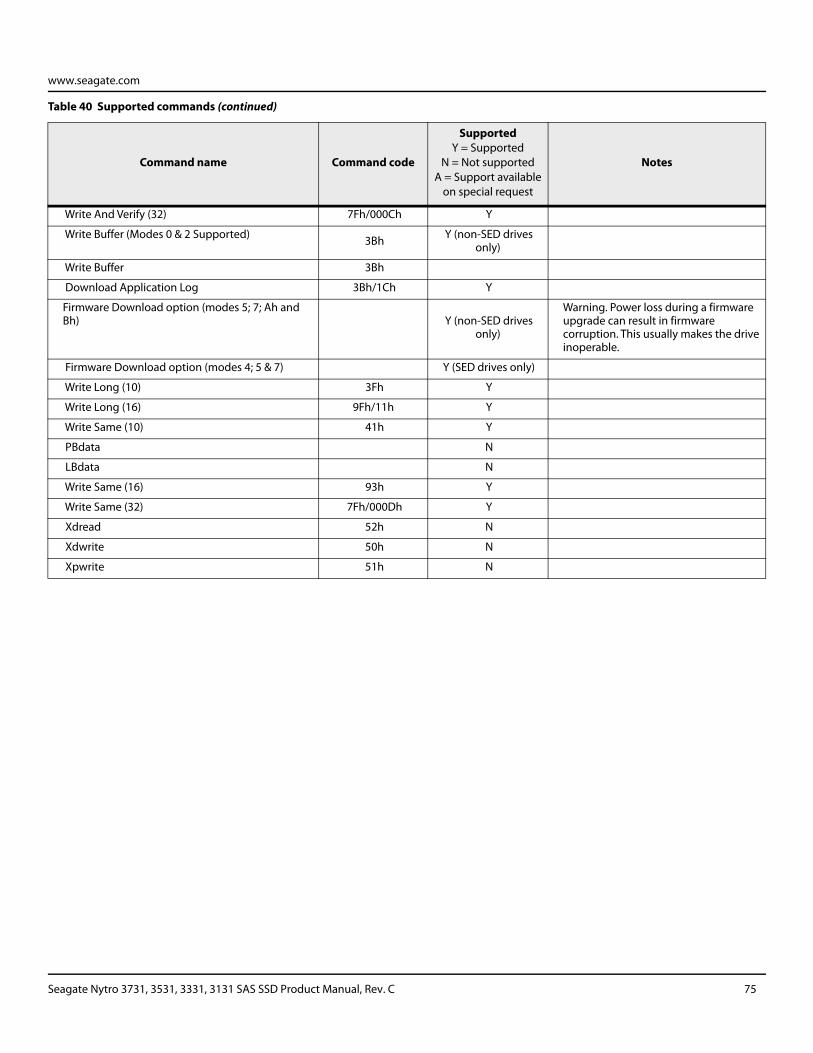
www.seagate.com
Write And Verify (32) 7Fh/000Ch Y
Write Buffer (Modes 0 & 2 Supported) 3Bh Y (non-SED drives only)
Write Buffer 3Bh
Download Application Log 3Bh/1Ch Y
Firmware Download option (modes 5; 7; Ah and Bh) Y (non-SED drives
only)
Warning. Power loss during a firmware upgrade can result in firmware corruption. This usually makes the drive inoperable.
Firmware Download option (modes 4; 5 & 7) Y (SED drives only)
Write Long (10) 3Fh Y
Write Long (16) 9Fh/11h Y
Write Same (10) 41h Y
PBdata N
LBdata N
Write Same (16) 93h Y
Write Same (32) 7Fh/000Dh Y
Xdread 52h N
Xdwrite 50h N
Xpwrite 51h N
Table 40 Supported commands (continued)
Command name Command code
SupportedY = Supported
N = Not supported A = Support available
on special request
Notes
Seagate Nytro 3731, 3531, 3331, 3131 SAS SSD Product Manual, Rev. C 75
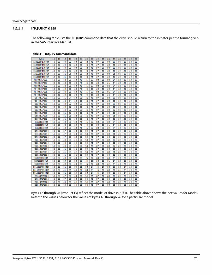
www.seagate.com
12.3.1 INQUIRY data
The following table lists the INQUIRY command data that the drive should return to the initiator per the format given in the SAS Interface Manual.
Table 41 - Inquiry command data
Bytes 16 through 26 (Product ID) reflect the model of drive in ASCII. The table above shows the hex values for Model. Refer to the values below for the values of bytes 16 through 26 for a particular model.
Seagate Nytro 3731, 3531, 3331, 3131 SAS SSD Product Manual, Rev. C 76
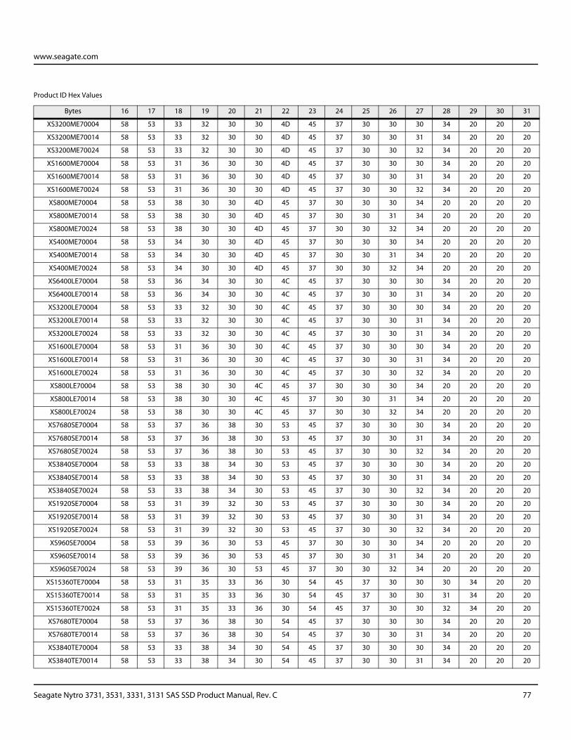
www.seagate.com
Product ID Hex Values
Bytes 16 17 18 19 20 21 22 23 24 25 26 27 28 29 30 31
XS3200ME70004 58 53 33 32 30 30 4D 45 37 30 30 30 34 20 20 20
XS3200ME70014 58 53 33 32 30 30 4D 45 37 30 30 31 34 20 20 20
XS3200ME70024 58 53 33 32 30 30 4D 45 37 30 30 32 34 20 20 20
XS1600ME70004 58 53 31 36 30 30 4D 45 37 30 30 30 34 20 20 20
XS1600ME70014 58 53 31 36 30 30 4D 45 37 30 30 31 34 20 20 20
XS1600ME70024 58 53 31 36 30 30 4D 45 37 30 30 32 34 20 20 20
XS800ME70004 58 53 38 30 30 4D 45 37 30 30 30 34 20 20 20 20
XS800ME70014 58 53 38 30 30 4D 45 37 30 30 31 34 20 20 20 20
XS800ME70024 58 53 38 30 30 4D 45 37 30 30 32 34 20 20 20 20
XS400ME70004 58 53 34 30 30 4D 45 37 30 30 30 34 20 20 20 20
XS400ME70014 58 53 34 30 30 4D 45 37 30 30 31 34 20 20 20 20
XS400ME70024 58 53 34 30 30 4D 45 37 30 30 32 34 20 20 20 20
XS6400LE70004 58 53 36 34 30 30 4C 45 37 30 30 30 34 20 20 20
XS6400LE70014 58 53 36 34 30 30 4C 45 37 30 30 31 34 20 20 20
XS3200LE70004 58 53 33 32 30 30 4C 45 37 30 30 30 34 20 20 20
XS3200LE70014 58 53 33 32 30 30 4C 45 37 30 30 31 34 20 20 20
XS3200LE70024 58 53 33 32 30 30 4C 45 37 30 30 31 34 20 20 20
XS1600LE70004 58 53 31 36 30 30 4C 45 37 30 30 30 34 20 20 20
XS1600LE70014 58 53 31 36 30 30 4C 45 37 30 30 31 34 20 20 20
XS1600LE70024 58 53 31 36 30 30 4C 45 37 30 30 32 34 20 20 20
XS800LE70004 58 53 38 30 30 4C 45 37 30 30 30 34 20 20 20 20
XS800LE70014 58 53 38 30 30 4C 45 37 30 30 31 34 20 20 20 20
XS800LE70024 58 53 38 30 30 4C 45 37 30 30 32 34 20 20 20 20
XS7680SE70004 58 53 37 36 38 30 53 45 37 30 30 30 34 20 20 20
XS7680SE70014 58 53 37 36 38 30 53 45 37 30 30 31 34 20 20 20
XS7680SE70024 58 53 37 36 38 30 53 45 37 30 30 32 34 20 20 20
XS3840SE70004 58 53 33 38 34 30 53 45 37 30 30 30 34 20 20 20
XS3840SE70014 58 53 33 38 34 30 53 45 37 30 30 31 34 20 20 20
XS3840SE70024 58 53 33 38 34 30 53 45 37 30 30 32 34 20 20 20
XS1920SE70004 58 53 31 39 32 30 53 45 37 30 30 30 34 20 20 20
XS1920SE70014 58 53 31 39 32 30 53 45 37 30 30 31 34 20 20 20
XS1920SE70024 58 53 31 39 32 30 53 45 37 30 30 32 34 20 20 20
XS960SE70004 58 53 39 36 30 53 45 37 30 30 30 34 20 20 20 20
XS960SE70014 58 53 39 36 30 53 45 37 30 30 31 34 20 20 20 20
XS960SE70024 58 53 39 36 30 53 45 37 30 30 32 34 20 20 20 20
XS15360TE70004 58 53 31 35 33 36 30 54 45 37 30 30 30 34 20 20
XS15360TE70014 58 53 31 35 33 36 30 54 45 37 30 30 31 34 20 20
XS15360TE70024 58 53 31 35 33 36 30 54 45 37 30 30 32 34 20 20
XS7680TE70004 58 53 37 36 38 30 54 45 37 30 30 30 34 20 20 20
XS7680TE70014 58 53 37 36 38 30 54 45 37 30 30 31 34 20 20 20
XS3840TE70004 58 53 33 38 34 30 54 45 37 30 30 30 34 20 20 20
XS3840TE70014 58 53 33 38 34 30 54 45 37 30 30 31 34 20 20 20
Seagate Nytro 3731, 3531, 3331, 3131 SAS SSD Product Manual, Rev. C 77
www.seagate.com
12.3.2 MODE SENSE data
The MODE SENSE command provides a way for the drive to report its operating parameters to the initiator. The drive maintains four sets of mode parameters:
1. Default values
Default values are hard-coded in the drive firmware stored in flash E-PROM (nonvolatile memory) on the drive’s PCB. These default values can be changed only by downloading a complete set of new firmware into the flash E-PROM. An initiator can request and receive from the drive a list of default values and use those in a MODE SELECT command to set up new current and saved values, where the values are changeable.
2. Saved values
Saved values are stored on the drive’s media using a MODE SELECT command. Only parameter values that are allowed to be changed can be changed by this method. Parameters in the saved values list that are not changeable by the MODE SELECT command get their values from default values storage.
When power is applied to the drive, it takes saved values from the media and stores them as current values in volatile memory. It is not possible to change the current values (or the saved values) with a MODE SELECT command before the drive is "ready." An attempt to do so results in a "Check Condition" status.
On drives requiring unique saved values, the required unique saved values are stored into the saved values storage location on the media prior to shipping the drive. Some drives may have unique firmware with unique default values also.
On standard OEM drives, the saved values are taken from the default values list and stored into the saved values storage location on the media prior to shipping.
3. Current values
Current values are volatile values being used by the drive to control its operation. A MODE SELECT command can be used to change the values identified as changeable values. Originally, current values are installed from saved or default values after a power on reset, hard reset, or Bus Device Reset message.
Seagate Nytro 3731, 3531, 3331, 3131 SAS SSD Product Manual, Rev. C 78
www.seagate.com
4. Changeable values
Changeable values form a bit mask, stored in nonvolatile memory, that dictates which of the current values and saved values can be changed by a MODE SELECT command. A one (1) indicates the value can be changed. A zero (0) indicates the value is not changeable. These are hex numbers representing the changeable values for Mode page 81. Note in columns 5 and 6 (bytes 04 and 05), there is 00h which indicates that in bytes 04 and 05 none of the bits are changeable. Note also that bytes 06, 07, 09, 10, and 11 are not changeable, because those fields are all zeros. In byte 02, hex value FF equates to the binary pattern 11111111. If there is a zero in any bit position in the field, it means that bit is not changeable. Since all of the bits in byte 02 are ones, all of these bits are changeable.
The changeable values list can only be changed by downloading new firmware.
NOTE Because there are often several different versions of drive control firmware in the total population of drives in the field, the MODE SENSE values given in the following tables may not exactly match those of some drives.
Seagate Nytro 3731, 3531, 3331, 3131 SAS SSD Product Manual, Rev. C 79
www.seagate.com
12.4 Miscellaneous operating features and conditions
The table below lists various features and conditions. A "Y" in the support column indicates the feature or condition is supported. An "N" in the support column indicates the feature or condition is not supported.
Table 42 - Miscellaneous features
Supported Feature or condition
N Automatic contingent allegiance
N Asynchronous event notification
Y Segmented caching
N Zero latency read
Y Queue tagging (up to 128 queue tags supported)
Y Deferred error handling
Y Parameter rounding (controlled by Round bit in MODE SELECT page 0)
N Reporting actual retry count in Extended Sense bytes 15, 16, and 17
Table 43 - Miscellaneous status
Supported Status
Y Good
Y Check condition
Y Condition met/good
Y Busy
Y Reservation conflict
Y Task set full
N ACA active
N ACA active, faulted initiator
N Task Aborted
Seagate Nytro 3731, 3531, 3331, 3131 SAS SSD Product Manual, Rev. C 80
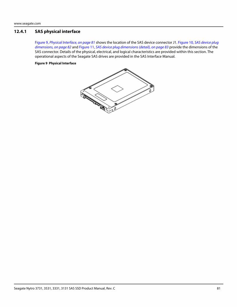
www.seagate.com
12.4.1 SAS physical interface
Figure 9, Physical Interface, on page 81 shows the location of the SAS device connector J1. Figure 10, SAS device plug dimensions, on page 82 and Figure 11, SAS device plug dimensions (detail), on page 83 provide the dimensions of the SAS connector. Details of the physical, electrical, and logical characteristics are provided within this section. The operational aspects of the Seagate SAS drives are provided in the SAS Interface Manual.
Figure 9 Physical Interface
Seagate Nytro 3731, 3531, 3331, 3131 SAS SSD Product Manual, Rev. C 81
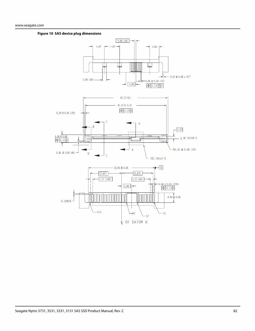
www.seagate.com
Figure 10 SAS device plug dimensions
Seagate Nytro 3731, 3531, 3331, 3131 SAS SSD Product Manual, Rev. C 82
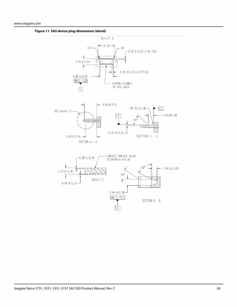
www.seagate.com
Figure 11 SAS device plug dimensions (detail)
Seagate Nytro 3731, 3531, 3331, 3131 SAS SSD Product Manual, Rev. C 83
www.seagate.com
12.4.2 Physical characteristics
This section defines physical interface connector.
12.4.3 Connector requirements
Contact a preferred connector manufacturer for mating part information. Part numbers for SAS connectors will be provided in a future revision of this publication when production parts are available from major connector manufacturers.
12.4.4 Electrical description
SAS drives use the device connector for:
DC power
SAS interface
Activity LED
This connector is designed to either plug directly into a backpanel or accept cables.
Seagate Nytro 3731, 3531, 3331, 3131 SAS SSD Product Manual, Rev. C 84
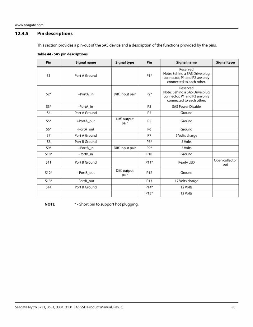
www.seagate.com
12.4.5 Pin descriptions
This section provides a pin-out of the SAS device and a description of the functions provided by the pins.
NOTE * - Short pin to support hot plugging.
Table 44 - SAS pin descriptions
Pin Signal name Signal type Pin Signal name Signal type
S1 Port A Ground P1*
ReservedNote: Behind a SAS Drive plug connector, P1 and P2 are only
connected to each other.
S2* +PortA_in Diff. input pair P2*
ReservedNote: Behind a SAS Drive plug connector, P1 and P2 are only
connected to each other.
S3* -PortA_in P3 SAS Power Disable
S4 Port A Ground P4 Ground
S5* +PortA_out Diff. output pair P5 Ground
S6* -PortA_out P6 Ground
S7 Port A Ground P7 5 Volts charge
S8 Port B Ground P8* 5 Volts
S9* +PortB_in Diff. input pair P9* 5 Volts
S10* -PortB_in P10 Ground
S11 Port B Ground P11* Ready LED Open collector out
S12* +PortB_out Diff. output pair P12 Ground
S13* -PortB_out P13 12 Volts charge
S14 Port B Ground P14* 12 Volts
P15* 12 Volts
Seagate Nytro 3731, 3531, 3331, 3131 SAS SSD Product Manual, Rev. C 85
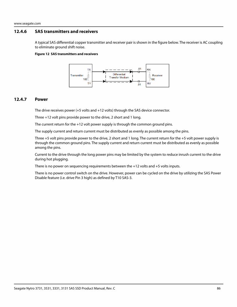
www.seagate.com
12.4.6 SAS transmitters and receivers
A typical SAS differential copper transmitter and receiver pair is shown in the figure below. The receiver is AC coupling to eliminate ground shift noise.
Figure 12 SAS transmitters and receivers
12.4.7 Power
The drive receives power (+5 volts and +12 volts) through the SAS device connector.
Three +12 volt pins provide power to the drive, 2 short and 1 long.
The current return for the +12 volt power supply is through the common ground pins.
The supply current and return current must be distributed as evenly as possible among the pins.
Three +5 volt pins provide power to the drive, 2 short and 1 long. The current return for the +5 volt power supply is through the common ground pins. The supply current and return current must be distributed as evenly as possible among the pins.
Current to the drive through the long power pins may be limited by the system to reduce inrush current to the drive during hot plugging.
There is no power on sequencing requirements between the +12 volts and +5 volts inputs.
There is no power control switch on the drive. However, power can be cycled on the drive by utilizing the SAS Power Disable feature (i.e. drive Pin 3 high) as defined by T10 SAS-3.
Seagate Nytro 3731, 3531, 3331, 3131 SAS SSD Product Manual, Rev. C 86
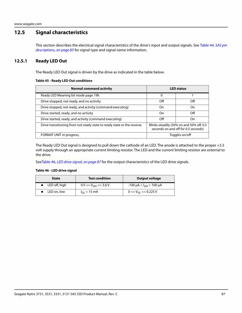
www.seagate.com
12.5 Signal characteristics
This section describes the electrical signal characteristics of the drive's input and output signals. See Table 44, SAS pin descriptions, on page 85 for signal type and signal name information.
12.5.1 Ready LED Out
The Ready LED Out signal is driven by the drive as indicated in the table below.
The Ready LED Out signal is designed to pull down the cathode of an LED. The anode is attached to the proper +3.3 volt supply through an appropriate current limiting resistor. The LED and the current limiting resistor are external to the drive.
SeeTable 46, LED drive signal, on page 87 for the output characteristics of the LED drive signals.
Table 45 - Ready LED Out conditions
Normal command activity LED status
Ready LED Meaning bit mode page 19h 0 1
Drive stopped, not ready, and no activity Off Off
Drive stopped, not ready, and activity (command executing) On On
Drive started, ready, and no activity On Off
Drive started, ready, and activity (command executing) Off On
Drive transitioning from not-ready state to ready state or the reverse. Blinks steadily (50% on and 50% off, 0.5 seconds on and off for 0.5 seconds)
FORMAT UNIT in progress, Toggles on/off
Table 46 - LED drive signal
State Test condition Output voltage
LED off, high 0 V <= VOH <= 3.6 V -100 μA < IOH < 100 μA
LED on, low IOL = 15 mA 0 <= VOL <= 0.225 V
Seagate Nytro 3731, 3531, 3331, 3131 SAS SSD Product Manual, Rev. C 87
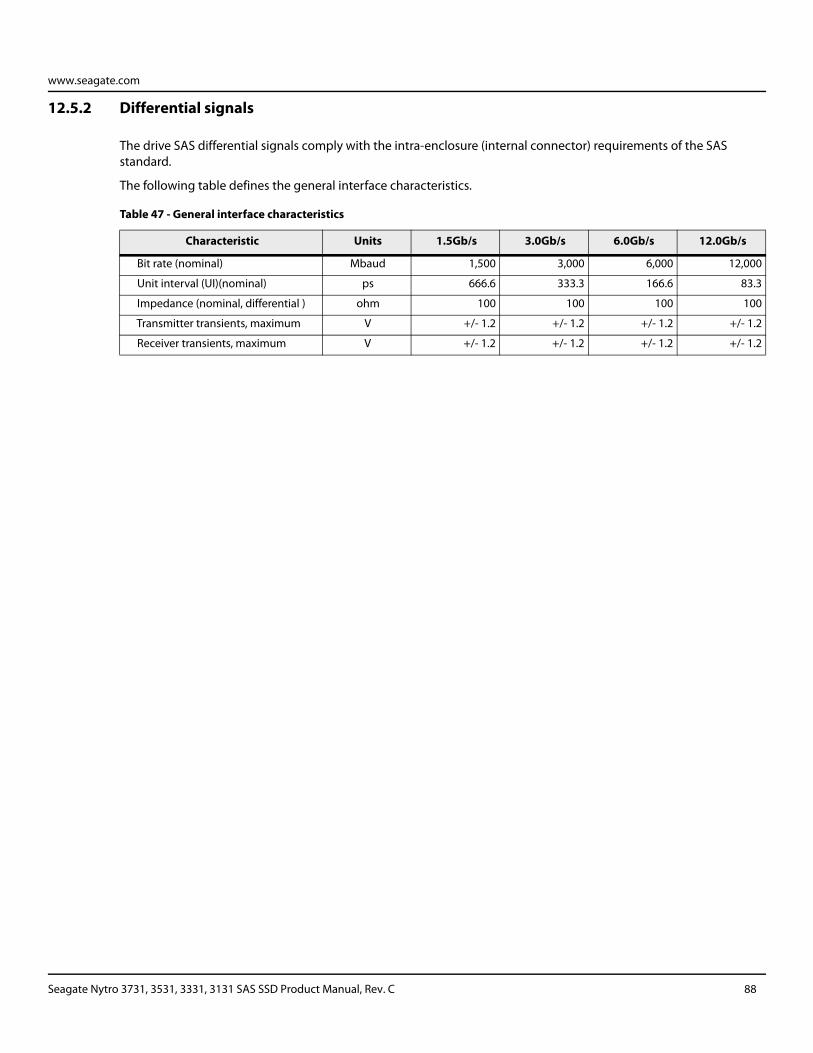
www.seagate.com
12.5.2 Differential signals
The drive SAS differential signals comply with the intra-enclosure (internal connector) requirements of the SAS standard.
The following table defines the general interface characteristics.
Table 47 - General interface characteristics
Characteristic Units 1.5Gb/s 3.0Gb/s 6.0Gb/s 12.0Gb/s
Bit rate (nominal) Mbaud 1,500 3,000 6,000 12,000
Unit interval (UI)(nominal) ps 666.6 333.3 166.6 83.3
Impedance (nominal, differential ) ohm 100 100 100 100
Transmitter transients, maximum V +/- 1.2 +/- 1.2 +/- 1.2 +/- 1.2
Receiver transients, maximum V +/- 1.2 +/- 1.2 +/- 1.2 +/- 1.2
Seagate Nytro 3731, 3531, 3331, 3131 SAS SSD Product Manual, Rev. C 88
www.seagate.com
12.6 SAS-3 Specification compliance
Seagate SAS-3 compatible drives are compliant with the latest SAS-3 Specification (T10/BSR INCITS 519 rev. 06).
The main difference from SAS-2 is the Tx and Rx training that allows the host and drive to adjust the amplitude and emphasis values to the channel. The receiver still employs Decision Feedback Equalizer (DFE) and Feed Forward Equalizer (FFE) circuitry to accomplish this training.
12.7 Additional information
Please contact the Seagate representative for SAS electrical details, if required.
For more information about the Phy, Link, Transport, and Applications layers of the SAS interface, refer to the Seagate SAS Interface Manual, part number 100293071.
For more information about the SCSI commands used by Seagate SAS drives, refer to the Seagate SCSI Commands Reference Manual, part number 100293068.
Seagate Nytro 3731, 3531, 3331, 3131 SAS SSD Product Manual, Rev. C 89
Seagate Technology LLCAMERICAS Seagate Technology LLC 10200 South De Anza Boulevard, Cupertino, California 95014, United States, 408-658-1000ASIA/PACIFIC Seagate Singapore International Headquarters Pte. Ltd. 7000 Ang Mo Kio Avenue 5, Singapore 569877, 65-6485-3888EUROPE, MIDDLE EAST AND AFRICA Seagate Technology (Netherlands) B.V. Koolhovenlaan 1, 1119 NB Schiphol-Rijk, Netherlands, 31-20-316-7300Publication Number: 100848978, Rev.CAugust 2019