scr/scrf series battery charger three phase · pdf filescr/scrf series battery charger three...
TRANSCRIPT
Operating and Service Instructions
SCR/SCRF SERIES BATTERY CHARGER THREE PHASE INPUT
3 Powdered Metals Drive North Haven, CT 06473-3209 Tel.: (203) 985-2500 Fax: (203) 985-2539 www.alcadusa.com
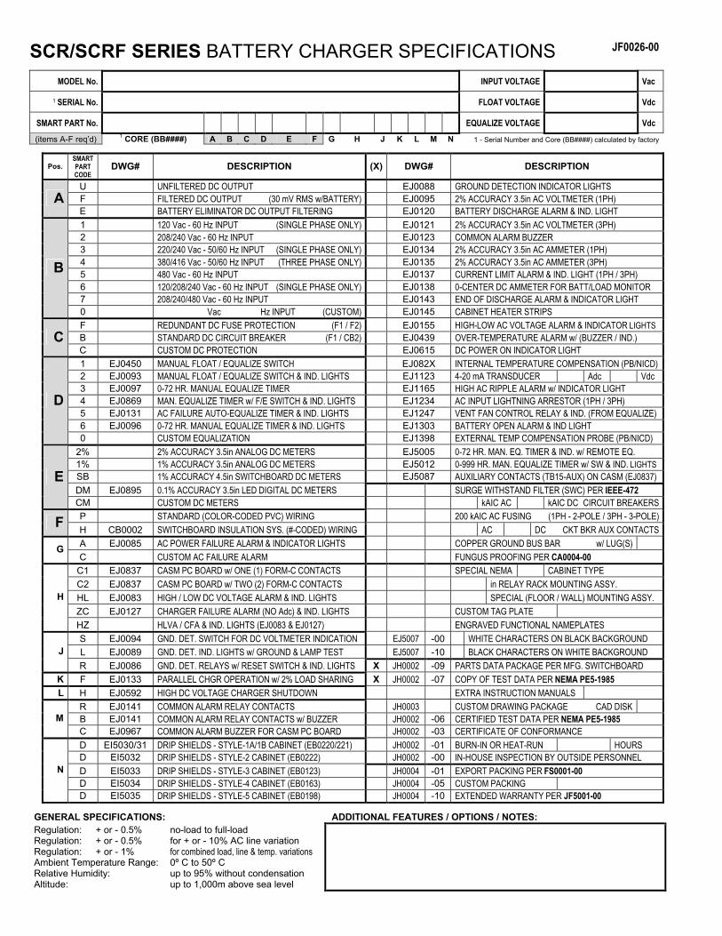
SCR/SCRF SERIES BATTERY CHARGER SPECIFICATIONS JF0026-00
MODEL No. INPUT VOLTAGE Vac
1 SERIAL No. FLOAT VOLTAGE Vdc
SMART PART No. EQUALIZE VOLTAGE Vdc
(items A-F req’d) 1 CORE (BB####) A B C D E F G H J K L M N 1 - Serial Number and Core (BB####) calculated by factory
Pos. SMART PART CODE
DWG# DESCRIPTION (X) DWG# DESCRIPTION
U UNFILTERED DC OUTPUT EJ0088 GROUND DETECTION INDICATOR LIGHTS F FILTERED DC OUTPUT (30 mV RMS w/BATTERY) EJ0095 2% ACCURACY 3.5in AC VOLTMETER (1PH) A E BATTERY ELIMINATOR DC OUTPUT FILTERING EJ0120 BATTERY DISCHARGE ALARM & IND. LIGHT 1 120 Vac - 60 Hz INPUT (SINGLE PHASE ONLY) EJ0121 2% ACCURACY 3.5in AC VOLTMETER (3PH) 2 208/240 Vac - 60 Hz INPUT EJ0123 COMMON ALARM BUZZER 3 220/240 Vac - 50/60 Hz INPUT (SINGLE PHASE ONLY) EJ0134 2% ACCURACY 3.5in AC AMMETER (1PH) 4 380/416 Vac - 50/60 Hz INPUT (THREE PHASE ONLY) EJ0135 2% ACCURACY 3.5in AC AMMETER (3PH) 5 480 Vac - 60 Hz INPUT EJ0137 CURRENT LIMIT ALARM & IND. LIGHT (1PH / 3PH) 6 120/208/240 Vac - 60 Hz INPUT (SINGLE PHASE ONLY) EJ0138 0-CENTER DC AMMETER FOR BATT/LOAD MONITOR 7 208/240/480 Vac - 60 Hz INPUT EJ0143 END OF DISCHARGE ALARM & INDICATOR LIGHT
B
0 Vac Hz INPUT (CUSTOM) EJ0145 CABINET HEATER STRIPS F REDUNDANT DC FUSE PROTECTION (F1 / F2) EJ0155 HIGH-LOW AC VOLTAGE ALARM & INDICATOR LIGHTS B STANDARD DC CIRCUIT BREAKER (F1 / CB2) EJ0439 OVER-TEMPERATURE ALARM w/ (BUZZER / IND.) C C CUSTOM DC PROTECTION EJ0615 DC POWER ON INDICATOR LIGHT 1 EJ0450 MANUAL FLOAT / EQUALIZE SWITCH EJ082X INTERNAL TEMPERATURE COMPENSATION (PB/NICD) 2 EJ0093 MANUAL FLOAT / EQUALIZE SWITCH & IND. LIGHTS EJ1123 4-20 mA TRANSDUCER Adc Vdc 3 EJ0097 0-72 HR. MANUAL EQUALIZE TIMER EJ1165 HIGH AC RIPPLE ALARM w/ INDICATOR LIGHT 4 EJ0869 MAN. EQUALIZE TIMER w/ F/E SWITCH & IND. LIGHTS EJ1234 AC INPUT LIGHTNING ARRESTOR (1PH / 3PH) 5 EJ0131 AC FAILURE AUTO-EQUALIZE TIMER & IND. LIGHTS EJ1247 VENT FAN CONTROL RELAY & IND. (FROM EQUALIZE) 6 EJ0096 0-72 HR. MANUAL EQUALIZE TIMER & IND. LIGHTS EJ1303 BATTERY OPEN ALARM & IND LIGHT
D
0 CUSTOM EQUALIZATION EJ1398 EXTERNAL TEMP COMPENSATION PROBE (PB/NICD) 2% 2% ACCURACY 3.5in ANALOG DC METERS EJ5005 0-72 HR. MAN. EQ. TIMER & IND. w/ REMOTE EQ. 1% 1% ACCURACY 3.5in ANALOG DC METERS EJ5012 0-999 HR. MAN. EQUALIZE TIMER w/ SW & IND. LIGHTS SB 1% ACCURACY 4.5in SWITCHBOARD DC METERS EJ5087 AUXILIARY CONTACTS (TB15-AUX) ON CASM (EJ0837) DM EJ0895 0.1% ACCURACY 3.5in LED DIGITAL DC METERS SURGE WITHSTAND FILTER (SWC) PER IEEE-472
E
CM CUSTOM DC METERS kAIC AC kAIC DC CIRCUIT BREAKERS P STANDARD (COLOR-CODED PVC) WIRING 200 kAIC AC FUSING (1PH - 2-POLE / 3PH - 3-POLE) F H CB0002 SWITCHBOARD INSULATION SYS. (#-CODED) WIRING AC DC CKT BKR AUX CONTACTS A EJ0085 AC POWER FAILURE ALARM & INDICATOR LIGHTS COPPER GROUND BUS BAR w/ LUG(S) G C CUSTOM AC FAILURE ALARM FUNGUS PROOFING PER CA0004-00
C1 EJ0837 CASM PC BOARD w/ ONE (1) FORM-C CONTACTS SPECIAL NEMA CABINET TYPE C2 EJ0837 CASM PC BOARD w/ TWO (2) FORM-C CONTACTS in RELAY RACK MOUNTING ASSY. HL EJ0083 HIGH / LOW DC VOLTAGE ALARM & IND. LIGHTS SPECIAL (FLOOR / WALL) MOUNTING ASSY. ZC EJ0127 CHARGER FAILURE ALARM (NO Adc) & IND. LIGHTS CUSTOM TAG PLATE
H
HZ HLVA / CFA & IND. LIGHTS (EJ0083 & EJ0127) ENGRAVED FUNCTIONAL NAMEPLATES S EJ0094 GND. DET. SWITCH FOR DC VOLTMETER INDICATION EJ5007 -00 WHITE CHARACTERS ON BLACK BACKGROUND L EJ0089 GND. DET. IND. LIGHTS w/ GROUND & LAMP TEST EJ5007 -10 BLACK CHARACTERS ON WHITE BACKGROUND J
R EJ0086 GND. DET. RELAYS w/ RESET SWITCH & IND. LIGHTS X JH0002 -09 PARTS DATA PACKAGE PER MFG. SWITCHBOARD K F EJ0133 PARALLEL CHGR OPERATION w/ 2% LOAD SHARING X JH0002 -07 COPY OF TEST DATA PER NEMA PE5-1985 L H EJ0592 HIGH DC VOLTAGE CHARGER SHUTDOWN EXTRA INSTRUCTION MANUALS
R EJ0141 COMMON ALARM RELAY CONTACTS JH0003 CUSTOM DRAWING PACKAGE CAD DISK B EJ0141 COMMON ALARM RELAY CONTACTS w/ BUZZER JH0002 -06 CERTIFIED TEST DATA PER NEMA PE5-1985 M C EJ0967 COMMON ALARM BUZZER FOR CASM PC BOARD JH0002 -03 CERTIFICATE OF CONFORMANCE D EI5030/31 DRIP SHIELDS - STYLE-1A/1B CABINET (EB0220/221) JH0002 -01 BURN-IN OR HEAT-RUN HOURS D EI5032 DRIP SHIELDS - STYLE-2 CABINET (EB0222) JH0002 -00 IN-HOUSE INSPECTION BY OUTSIDE PERSONNEL D EI5033 DRIP SHIELDS - STYLE-3 CABINET (EB0123) JH0004 -01 EXPORT PACKING PER FS0001-00 D EI5034 DRIP SHIELDS - STYLE-4 CABINET (EB0163) JH0004 -05 CUSTOM PACKING
N
D EI5035 DRIP SHIELDS - STYLE-5 CABINET (EB0198) JH0004 -10 EXTENDED WARRANTY PER JF5001-00
GENERAL SPECIFICATIONS: ADDITIONAL FEATURES / OPTIONS / NOTES: Regulation: + or - 0.5% no-load to full-load Regulation: + or - 0.5% for + or - 10% AC line variation Regulation: + or - 1% for combined load, line & temp. variations Ambient Temperature Range: 0º C to 50º C Relative Humidity: up to 95% without condensation Altitude: up to 1,000m above sea level
i
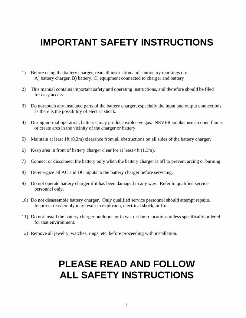
IMPORTANT SAFETY INSTRUCTIONS
1) Before using the battery charger, read all instruction and cautionary markings on: A) battery charger, B) battery, C) equipment connected to charger and battery 2) This manual contains important safety and operating instructions, and therefore should be filed for easy access. 3) Do not touch any insulated parts of the battery charger, especially the input and output connections, as there is the possibility of electric shock. 4) During normal operation, batteries may produce explosive gas. NEVER smoke, use an open flame, or create arcs in the vicinity of the charger or battery. 5) Maintain at least 1ft (0.3m) clearance from all obstructions on all sides of the battery charger. 6) Keep area in front of battery charger clear for at least 4ft (1.3m). 7) Connect or disconnect the battery only when the battery charger is off to prevent arcing or burning. 8) De-energize all AC and DC inputs to the battery charger before servicing. 9) Do not operate battery charger if it has been damaged in any way. Refer to qualified service personnel only. 10) Do not disassemble battery charger. Only qualified service personnel should attempt repairs. Incorrect reassembly may result in explosion, electrical shock, or fire. 11) Do not install the battery charger outdoors, or in wet or damp locations unless specifically ordered for that environment. 12) Remove all jewelry, watches, rings, etc. before proceeding with installation.
PLEASE READ AND FOLLOW ALL SAFETY INSTRUCTIONS
ii
TABLE OF CONTENTS Page No. SCR/SCRF BATTERY CHARGER SPECIFICATIONS (JF0026-00).......................... (inside front cover) IMPORTANT SAFETY INSTRUCTIONS ................................................................................................ i TABLE OF CONTENTS...................................................................................................................... ii-iii SECTION II - INSTALLATION AND OPERATION 1. Safety Notice ......................................................................................................................................................2 2. Application .........................................................................................................................................................2 3. Installation..........................................................................................................................................................2 4. Placing Charger in Service .................................................................................................................................3 5. Adjustments of Float & Equalizing Charge .......................................................................................................3 6. Manual Equalize Timer ......................................................................................................................................3 7. Maintenance .......................................................................................................................................................4 8. Normal Performance ..........................................................................................................................................4 9. Description of Operation ....................................................................................................................................5 a. Power Transformer........................................................................................................................................5 b. Rectifier Section ............................................................................................................................................5 c. Control Module .............................................................................................................................................5 d. Filter Section .................................................................................................................................................5 SECTION III - TROUBLESHOOTING 1. CAUTION Notice .............................................................................................................................................6 2. Troubleshooting Procedure ................................................................................................................................6 3. Testing of Components ......................................................................................................................................6 a. External Circuit Wiring .................................................................................................................................6 b. Power Transformer (T1)................................................................................................................................7 c. Circuit Breakers (CB1 / CB2) .......................................................................................................................7 d. Surge Suppressors (SS1 / SS2 / SS3 / SS4)...................................................................................................7 e. Rectifier Diodes (CR4 / CR5 / CR6).............................................................................................................7 f. SCR Diodes (SCR1 / SCR2 / SCR3).............................................................................................................8 g. Control Module (A1).....................................................................................................................................8 h. Current Sensing Resistor (SH1) ....................................................................................................................9 j. DC Voltmeter (M2) .......................................................................................................................................9 k. DC Ammeter (M1) ......................................................................................................................................10 m. Filter Capacitors (C1 / C2) ..........................................................................................................................10 n. Internal Wiring ............................................................................................................................................10 SECTION IV - SYSTEM ADJUSTMENTS 1. Voltage Adjustments and Response .................................................................................................................11 a. Float Adjustment .........................................................................................................................................11 b. Equalize Adjustment ...................................................................................................................................12 2. Current Limit Response and Adjustment .........................................................................................................13 a. Checks and Adjustments .............................................................................................................................13 b. Checks to Make if Malfunctioning..............................................................................................................13
iii
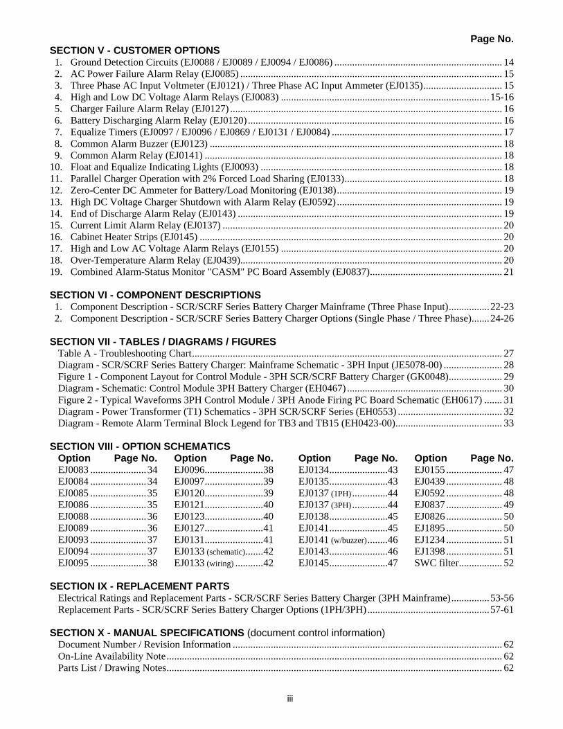
Page No. SECTION V - CUSTOMER OPTIONS 1. Ground Detection Circuits (EJ0088 / EJ0089 / EJ0094 / EJ0086) .................................................................. 14 2. AC Power Failure Alarm Relay (EJ0085) ....................................................................................................... 15 3. Three Phase AC Input Voltmeter (EJ0121) / Three Phase AC Input Ammeter (EJ0135)............................... 15 4. High and Low DC Voltage Alarm Relays (EJ0083) ..................................................................................15-16 5. Charger Failure Alarm Relay (EJ0127) ........................................................................................................... 16 6. Battery Discharging Alarm Relay (EJ0120) .................................................................................................... 16 7. Equalize Timers (EJ0097 / EJ0096 / EJ0869 / EJ0131 / EJ0084) ................................................................... 17 8. Common Alarm Buzzer (EJ0123) ................................................................................................................... 18 9. Common Alarm Relay (EJ0141) ..................................................................................................................... 18 10. Float and Equalize Indicating Lights (EJ0093) ............................................................................................... 18 11. Parallel Charger Operation with 2% Forced Load Sharing (EJ0133).............................................................. 18 12. Zero-Center DC Ammeter for Battery/Load Monitoring (EJ0138)................................................................. 19 13. High DC Voltage Charger Shutdown with Alarm Relay (EJ0592) ................................................................. 19 14. End of Discharge Alarm Relay (EJ0143) ........................................................................................................ 19 15. Current Limit Alarm Relay (EJ0137) .............................................................................................................. 20 16. Cabinet Heater Strips (EJ0145) ....................................................................................................................... 20 17. High and Low AC Voltage Alarm Relays (EJ0155) ....................................................................................... 20 18. Over-Temperature Alarm Relay (EJ0439)....................................................................................................... 20 19. Combined Alarm-Status Monitor "CASM" PC Board Assembly (EJ0837).................................................... 21 SECTION VI - COMPONENT DESCRIPTIONS 1. Component Description - SCR/SCRF Series Battery Charger Mainframe (Three Phase Input)................22-23 2. Component Description - SCR/SCRF Series Battery Charger Options (Single Phase / Three Phase).......24-26 SECTION VII - TABLES / DIAGRAMS / FIGURES Table A - Troubleshooting Chart.......................................................................................................................... 27 Diagram - SCR/SCRF Series Battery Charger: Mainframe Schematic - 3PH Input (JE5078-00) ....................... 28 Figure 1 - Component Layout for Control Module - 3PH SCR/SCRF Battery Charger (GK0048)..................... 29 Diagram - Schematic: Control Module 3PH Battery Charger (EH0467) ............................................................. 30 Figure 2 - Typical Waveforms 3PH Control Module / 3PH Anode Firing PC Board Schematic (EH0617) ....... 31 Diagram - Power Transformer (T1) Schematics - 3PH SCR/SCRF Series (EH0553) ......................................... 32 Diagram - Remote Alarm Terminal Block Legend for TB3 and TB15 (EH0423-00).......................................... 33 SECTION VIII - OPTION SCHEMATICS Option Page No. Option Page No. Option Page No. Option Page No. EJ0083 ......................34 EJ0096.......................38 EJ0134.......................43 EJ0155 ...................... 47 EJ0084 ......................34 EJ0097.......................39 EJ0135.......................43 EJ0439 ...................... 48 EJ0085 ......................35 EJ0120.......................39 EJ0137 (1PH) ..............44 EJ0592 ...................... 48 EJ0086 ......................35 EJ0121.......................40 EJ0137 (3PH) ..............44 EJ0837 ...................... 49 EJ0088 ......................36 EJ0123.......................40 EJ0138.......................45 EJ0826 ...................... 50 EJ0089 ......................36 EJ0127.......................41 EJ0141.......................45 EJ1895 ...................... 50 EJ0093 ......................37 EJ0131.......................41 EJ0141 (w/buzzer)........46 EJ1234 ...................... 51 EJ0094 ......................37 EJ0133 (schematic).......42 EJ0143.......................46 EJ1398 ...................... 51 EJ0095 ......................38 EJ0133 (wiring) ...........42 EJ0145.......................47 SWC filter................. 52 SECTION IX - REPLACEMENT PARTS Electrical Ratings and Replacement Parts - SCR/SCRF Series Battery Charger (3PH Mainframe)...............53-56 Replacement Parts - SCR/SCRF Series Battery Charger Options (1PH/3PH)................................................57-61 SECTION X - MANUAL SPECIFICATIONS (document control information) Document Number / Revision Information .......................................................................................................... 62 On-Line Availability Note.................................................................................................................................... 62 Parts List / Drawing Notes.................................................................................................................................... 62
2
SECTION II INSTALLATION AND OPERATION
1. SAFETY NOTICE
CAUTION! READ “IMPORTANT SAFETY INSTRUCTIONS” ON PAGE i. There are dangerous voltages within the battery charger cabinet! a. Only qualified personnel should attempt to adjust or service this equipment. b. Refer to instruction manual for service procedures and CAUTION notes. 2. APPLICATION
Specifications: The silicon controlled rectifier is designed to maintain a system voltage within + or - 0.5% of the set value without exceeding its rated output current. It will maintain + or - 0.5% with input voltage variations 10% above or below the rated input AC voltage and with 5% frequency variations. The charger is designed, primarily, to operate only when connected to a battery load. It can be operated as a battery eliminator into a resistive load up to full rated output at increased ripple. Filtered type chargers will have a ripple content less than 30 mV RMS under steady state conditions with the charger connected to a battery having an 8-hour Amp-Hour rating of at least 4 times the full load current rating of the charger. Other connected loads such as DC-to-DC power supplies or inverters, may put ripple on the battery appreciably above 30 mV. Unfiltered chargers should not be used with critical loads such as communication systems, amplifiers and instrumentation systems, but should only be used for non-critical applications such as engine cranking. This charger can be used on any number of lead-acid, nickel-cadmium, or nickel-iron cells as long as the desired float and/or equalize voltages are within the range of the charger. 3. INSTALLATION
a. Location: Select a clean, dry location for the charger. It may be located in the battery room, but not over the battery, and must be mounted upright. The openings for ventilation in the top, bottom and sides of the cabinet should not be obstructed, as they provide convection cooling and ventilation. Ambient temperatures between 32° F and 122° F, and elevations up to 3,300 feet above sea level, will not affect the performance of the charger. Operation at higher temperatures, or at higher elevations, is possible if the ampere output is de-rated in accordance with published information, and if the charger is custom ordered for these operating ambient conditions. b. Wire Sizes AC: Wire sizes for the AC wiring may be selected by consulting the data on the nameplate for input amperage. Local electrical or NEMA standards should dictate appropriate wire size. Most codes specify that the AC wiring size must match the current rating of the input circuit breaker or fuses. c. Wire Sizes DC: The size of the charger leads should be selected to (a) carry the charger (ampere) current rating, and also (b) provide less than 0.5 volt total drop at rated current in the loop or leads between the charger and battery terminals. Choose the larger wire size that meets conditions (a) and (b). Do not undersize. It is good practice to keep the DC leads as short as possible and to keep them together as a pair to obtain low inductance. Likewise, it is good practice to avoid sharp bends and to run both DC leads together if run in conduit. d. Input Power: These chargers are nominal 208V, 240V, 480V (60 Hz) or 380/416V (50 Hz) AC three phase. If the AC input data as supplied with the charger does not agree with the AC supply voltage at the installation site, do not connect the charger to the AC line. The AC voltage must be within +/- 10% of the rated input voltage of the charger. If not, consult your power company or the battery charger manufacturer. These three phase input power chargers are not phase rotation sensitive, and thus any combination of three phase input AC wiring may be used.
3
4. PLACING CHARGER IN SERVICE
a. With the AC and DC breakers OFF and the system in float mode, install the charger making AC and DC connections, as described in Section II, 3, and in accord with local regulations as they apply. b. After connecting the lead from the positive (+) battery terminal to the positive (+) terminal on the charger and the lead from the negative (-) battery terminal to the (-) terminal on the charger, observe the voltmeter. It should read the correct polarity and be approximately the battery open circuit voltage (this is 2.0 volts per cell for lead-acid batteries and 1.2 volts per cell for nickel cadmium batteries). For example, a 60-cell lead-acid battery should read about 2 x 60 cells = 120 volts. This is a check to indicate that all cells are in a true series (none connected in reverse). The open circuit voltage should be about 8% to 10% below the rated float voltage. c. The charger can now be energized, by first closing the DC breaker to supply voltage for the control circuits then closing the AC breaker. Set the charger to “float”. The AC power ON pilot light should light, and the ammeter should indicate charger output current. It is to be expected that the meter may show up to 110% current rating of the charger; the 110% being the factory setting of the current limit control. d. The factory preset float voltage adjustment value is listed on the inside front cover. When this value is reached, the charger ammeter should show a slow decrease in current, eventually down to a stabilized value. Please note that whenever a charger is in a current limit condition, the output voltage is automatically reduced to a value below the set float or equalize voltage. The voltage will not increase to normal value until the battery’s state of charge increases, causing the charger current to decrease to a value equal to or less than the rated current. e. The factory preset equalize voltage value is also listed on the inside front cover. Assuming this is as desired, the Float/Equalize switch may be switched to “Equalize”, to check the charger performance at this voltage value. If a Manual Equalize Timer (option) has been included, turn it clockwise to activate the equalize charger mode. The charger ammeter may again go up to current limit until the equalizing charger voltage is reached. The length of time required to reach this level depends on the state of charge of the battery, and the ampere rating of the charger versus the battery Ampere-hour rating. f. With the charger operating at the desired float and equalizing voltage values, the system can be considered installed and ready for service. 5. ADJUSTMENTS OF FLOAT & EQUALIZING CHARGE (also see Section IV, 1)
a. Each adjustment is made by means of a potentiometer with a slotted shaft for a screwdriver. The potentiometers are front-panel mounted and appropriately marked. A lock nut on each potentiometer is provided and should be tightened after the proper adjustment is completed. This prevents any accidental mis-adjustments of the settings. The voltage response may be slow if a rise in voltage adjustment is desired, because the battery state of charger and connected load must be considered. Turning the shaft clockwise will raise the voltage, and turning counter-clockwise will lower the voltage. b. Since accuracy of measurement is important when setting float and equalizing voltages, a precision portable VoltOhmmeter with at least 1% accuracy is recommended for these DC measurements. A conventional VoltOhmmeter or analyzer such as the Simpson Model 260 is also satisfactory, but is not as accurate. c. Any setting of the float voltage or equalizing charger voltage should not be considered final until the ammeter shows less than charger rated current, and voltage does not change after several hours of operation. 6. MANUAL EQUALIZE TIMER (OPTIONAL)
a. This timer is provided to obtain a charge up to 72 hours, at a slightly higher value than the ordinary float voltage. The timer may be used for recharging older batteries, or for a freshening charge on new batteries. For a detailed explanation of operation see Section V (Customer Options).
4
7. MAINTENANCE
a. This charger is designed to require a minimum of maintenance. There are no rotating parts except in the optional timer and all components have a nominally indefinite life with no expected aging effect. It should be kept clean, dry and checked periodically to make sure all connections are tight. If necessary, dry air may be used to blow dust out of the interior. In the event of any irregular operation, examine, and tighten if necessary, all internal and external connections and check circuits for continuity (see schematic diagram on page 28). If the difficulty cannot be remedied, contact the manufacturer. 8. NORMAL PERFORMANCE
a. Assuming that the charger has been operating in the float position, an indication of normal performance can be obtained by setting the FLOAT/EQUALIZE switch in the equalize position (turn timer off zero). Increased charge current will show on charger ammeter until the battery reaches the equalize voltage. At this point the current should slowly decrease. b. If the charger has been operating in the equalize voltage position, turn SW1 to FLOAT (turn the timer manually to zero). The charger will indicate zero or little output current until the float voltage is reached. At this point, the current should increase slowly to the system load value, (the battery is now “floating” across the line with approximately equal input and output currents). c. When operating normally, the current limit control will limit the maximum charger output current to approximately 110% of the rated charge current. In case of a high DC current demand, the current limit control will keep the charger output within safe values without tripping the DC circuit breaker or the AC breaker.
5
9. DESCRIPTION OF OPERATION
There are four major sections of the SCR three-phase charger, which work together to produce stable, regulated, filtered output. The functions of these four sections may be described as follows. a. The Power Transformer (T1): This section includes T1 and its associated input protection. Its purpose is basically to supply an AC voltage of the proper magnitude and capacity to the rectifier section. It also supplies various other voltages used by the control unit and accessories. It is connected to an AC source by means of a circuit breaker. b. The Rectifier Section: This section consists mainly of the voltage regulating silicon controlled rectifiers and the power rectifier diodes. It accepts the AC voltage from the transformer, rectifies this voltage to DC, and controls the voltage’s magnitude so that the charger output is regulated at all times. The firing angle of the SCRs is controlled by the action of the control module. Both the SCRs and the diodes are protected from AC and DC surge voltages by means of the metal-oxide varistor surge suppressors. c. The Control Module: This printed circuit board generates the three-phase phase-fired gate signals that turn on the SCR diodes in response to the charging requirements of the battery load. The output voltage of the charger is monitored by the voltage feedback circuit and advances or retards the phase angle of the trigger pulses so that the output voltage is maintained essentially constant. This is accomplished by comparing a small portion of the output voltage to a stable voltage reference. An error signal is created proportional to the differential voltage. This error signal is then used to alter the phase angle of the SCR gate trigger pulses in order to correct the output voltage. The load current is also monitored by the circuit so that when its value exceeds an arbitrary value (110% rated current) the system is “phased back” to limit the output current to no more than 110% of its rated value. d. The Filter Section: (1). Depending on the application, the charger may be unfiltered. In this case, one filter choke, L1, is utilized not for filtering but for phase correction of the highly leading current-voltage condition created by the batteries during the charging pulses. The batteries represent a very large capacitor in shunt with a resistive load. This creates out-of-phase current problems for the SCR diodes causing non-uniform triggering problems particularly at low load currents. The single filter choke corrects this condition and also aids the ratio of average current to RMS current flowing in the circuit. (2). For filtered units, the objective is to remove the charging ripple at the battery terminals. To accomplish this a "T" or "double-L" section filter consisting of inductors L1 and L2 and capacitors C1 and C2 are used. C1 and C2 may consist of one or more individual capacitors. The degree of filtering required dictates whether the "T" or "double-L" configuration is used. The "double-L" section filter is normally used to reduce the ripple to 0.06% of nominal output voltage when the charger is operated as a filtered eliminator.
6
SECTION III TROUBLESHOOTING
1. CAUTION NOTICE
Before troubleshooting, always isolate and de-energize the charger by opening the AC circuit breaker (CB1) and the DC circuit breaker (CB2). This avoids the possibility of high short circuit current damaging the charger, tools, test equipment, or injuring personnel. NOTE: Circuit breaker terminals (CBx), printed circuit boards (Ax) and terminals/terminal blocks (TB1, TB2, TB3, TB5 & TB15) have dangerous voltage across them, even when both circuit breakers are open. After isolating the charger, check that the voltage across the filter capacitors (C1/C2) is zero. Once charged, they will take several minutes to discharge if bleeder resistor (R1) is open. If DC circuit breaker (CB2) is not provided, remove the DC fuses (F1/F2) in order to isolate the charger from the battery. AFTER LOCATING THE CHARGER PROBLEM, ALWAYS DE-ENERGIZE ALL AC AND DC CHARGER INPUTS AT THE POWER SOURCE BEFORE SERVICING. 2. TROUBLESHOOTING PROCEDURE
a. When a charger is not operating properly, the cause must be determined by checking various components until the fault is located. b. The major components do not have to be checked in the order as listed in Section II, 9, since a charger may exhibit a number of difficulties, each with different symptoms. In many cases, failure of one component may cause another component or part to fail. Therefore, the following paragraphs treat major components, functional circuits and parts individually (or by symptom). Together with serviceability measurements and tests, the faulty part or component should be located. c. Most of the following checks can be performed with an oscilloscope, a VoltOhmmeter (similar to a Simpson Model 260) and an SCR tester. d. Consult the trouble-shooting chart in Table A on page 27. When using the table, first locate the fault symptom observed (in the left hand column) then follow the sequence for checking components in the numerical order listed (1, 2, 3 etc.) for that particular symptom. Follow this sequence until the trouble is located. After correcting the trouble, check the charger for normal performance as described in Section II, 8. e. In addition to those symptoms listed in Table A, the following procedure should be followed for any condition:
• Check voltage of the AC supply to insure that it is within 10% of the value of the specified input voltage.
• Examine charger for any evident loose or improper connections, particularly at the control unit, transformer and input/output terminal board.
• Check continuity of battery circuit by comparing voltage at charger terminals with total of cell voltages.
• Check accuracy of voltmeter and ammeter on the charger. 3. TESTING OF COMPONENTS
a. External Circuit Wiring 1. When no line voltage exists between TB1 input terminals (L1 to L2, L2 to L3 & L3 to L1), check the AC line back to source. 2. With no output, or a low output, the external DC wiring may be at fault. Check the wiring between charger and battery to see that it is properly installed. Make certain that terminals are tight and clean, and that the DC wiring is free from grounds. The total operating voltage drop in the loop or leads between the charger and battery terminals should never exceed 0.5 volt (at rated charge current), and preferably should be kept considerably below this limit by using a sufficiently large wire size.
7
b. Power Transformer (T1) 1. With the AC and DC circuit breakers open or OFF, open the cabinet and carefully check the line voltage across line terminals on TB1, terminals (L1 to L2, L2 to L3 & L3 to L1). If no AC voltage is indicated, refer to Section III, 3, a, 1. Check the wiring connections to ascertain that the unit has the proper primary tap connections for the line voltage indicated. Turn on the AC circuit breaker (CB1). Check that the voltage at the primary is the same as that of the line. If this is not the case, CB1 or the wiring between it and T1 is open. In this case, proceed with checks under Section III, 3, c, 1. 2. Check AC secondary voltage on T1 (see Table B below for expected voltage values). If secondary voltages are much less than indicated or not balanced, then either T1 is at fault or the power regulating devices (SCR1, SCR2 or SCR3) are faulty.
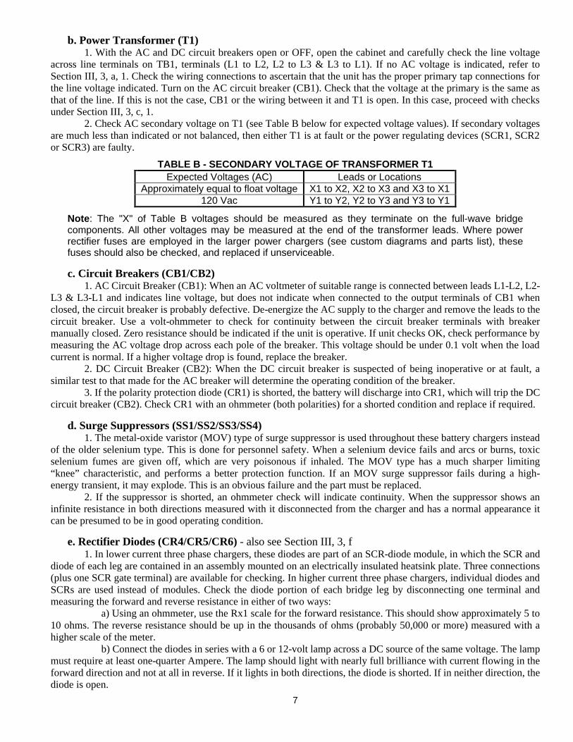
TABLE B - SECONDARY VOLTAGE OF TRANSFORMER T1 Expected Voltages (AC) Leads or Locations
Approximately equal to float voltage X1 to X2, X2 to X3 and X3 to X1 120 Vac Y1 to Y2, Y2 to Y3 and Y3 to Y1
Note: The "X" of Table B voltages should be measured as they terminate on the full-wave bridge components. All other voltages may be measured at the end of the transformer leads. Where power rectifier fuses are employed in the larger power chargers (see custom diagrams and parts list), these fuses should also be checked, and replaced if unserviceable.
c. Circuit Breakers (CB1/CB2) 1. AC Circuit Breaker (CB1): When an AC voltmeter of suitable range is connected between leads L1-L2, L2-L3 & L3-L1 and indicates line voltage, but does not indicate when connected to the output terminals of CB1 when closed, the circuit breaker is probably defective. De-energize the AC supply to the charger and remove the leads to the circuit breaker. Use a volt-ohmmeter to check for continuity between the circuit breaker terminals with breaker manually closed. Zero resistance should be indicated if the unit is operative. If unit checks OK, check performance by measuring the AC voltage drop across each pole of the breaker. This voltage should be under 0.1 volt when the load current is normal. If a higher voltage drop is found, replace the breaker. 2. DC Circuit Breaker (CB2): When the DC circuit breaker is suspected of being inoperative or at fault, a similar test to that made for the AC breaker will determine the operating condition of the breaker. 3. If the polarity protection diode (CR1) is shorted, the battery will discharge into CR1, which will trip the DC circuit breaker (CB2). Check CR1 with an ohmmeter (both polarities) for a shorted condition and replace if required.
d. Surge Suppressors (SS1/SS2/SS3/SS4) 1. The metal-oxide varistor (MOV) type of surge suppressor is used throughout these battery chargers instead of the older selenium type. This is done for personnel safety. When a selenium device fails and arcs or burns, toxic selenium fumes are given off, which are very poisonous if inhaled. The MOV type has a much sharper limiting “knee” characteristic, and performs a better protection function. If an MOV surge suppressor fails during a high-energy transient, it may explode. This is an obvious failure and the part must be replaced. 2. If the suppressor is shorted, an ohmmeter check will indicate continuity. When the suppressor shows an infinite resistance in both directions measured with it disconnected from the charger and has a normal appearance it can be presumed to be in good operating condition.
e. Rectifier Diodes (CR4/CR5/CR6) - also see Section III, 3, f 1. In lower current three phase chargers, these diodes are part of an SCR-diode module, in which the SCR and diode of each leg are contained in an assembly mounted on an electrically insulated heatsink plate. Three connections (plus one SCR gate terminal) are available for checking. In higher current three phase chargers, individual diodes and SCRs are used instead of modules. Check the diode portion of each bridge leg by disconnecting one terminal and measuring the forward and reverse resistance in either of two ways: a) Using an ohmmeter, use the Rx1 scale for the forward resistance. This should show approximately 5 to 10 ohms. The reverse resistance should be up in the thousands of ohms (probably 50,000 or more) measured with a higher scale of the meter. b) Connect the diodes in series with a 6 or 12-volt lamp across a DC source of the same voltage. The lamp must require at least one-quarter Ampere. The lamp should light with nearly full brilliance with current flowing in the forward direction and not at all in reverse. If it lights in both directions, the diode is shorted. If in neither direction, the diode is open.
8
2. Note that semiconductors usually short in pairs in bridge circuits, seldom as single units, and it is rare that all six semiconductors in a bridge are found defective. When diodes fail it usually is because of surge voltages. Therefore, surge suppressors (SS1, SS2, SS3 & SS4) should also be checked to determine that they are operative (refer to Section III, 3, d).
f. SCR Diodes (SCR1/SCR2/SCR3) - also see Section III, 3, e 1. These devices are either part of the SCR-diode modules or are individual components as described in Section III, 3, e above. Power regulating devices (SCR1, SCR2 & SCR3) are silicon-controlled rectifiers, which cannot be checked using the same method as used with rectifier diodes by forward and reverse resistance checks, since the SCR will always show a high resistance until triggered. 2. The operation of the SCR can be checked with an oscilloscope. The control module assembly (A1) produces the gate-firing voltage signal. The oscilloscope should be GROUND ISOLATED for these tests. This is normally done, using a line isolation transformer, in which the secondary that powers the oscilloscope is UNGROUNDED. Alternatively, a battery-powered portable oscilloscope can be used. The gate signal may be checked on the control module (see Section III, 3, g) or where the twisted-pair trigger leads terminate on the SCR-diode module. The same signal should appear at both points. Absence of the signal indicates that the control module is defective, not the SCR (see Section III, 3, g). 3. If the charger AC input breaker (CB1) trips immediately, and a shorted SCR is suspected, a simple check with an ohmmeter can be made. Turn off CB1 and CB2. Connect to the anode and to the cathode, and adjust to the direct reading scale of the ohmmeter. If a low resistance is observed, reverse the leads and again check the resistance. If this reading is also low, the SCR is shorted and should be replaced. 4. An SCR can also be checked for operation with a Simpson Model 260 volt-ohmmeter. With the black lead in common and red lead in +, put polarity switch to + DC. Connect the red lead to the anode and the black lead to the cathode. The meter should now indicate high resistance above 50,000 ohms (when on the R x 10,000 scale). With the leads connected as above, set the function switch to R x 1 and touch the gate to the anode. This should fire the SCR and give a reading of approximately 5-20 ohms. This shows the SCR has been turned on. On very small SCRs, this reading will hold after removing the gate lead. This is latched-on and can be unlatched by opening the cathode lead. Larger SCRs will not stay on with the current available with Simpson meter. The Simpson may not have enough current to gate or turn on extremely large SCRs (400 amp and up). 5. If the charger output is too high, unplug the control module and turn on the charger. With no gate signals the charger should have zero output. If there is still current output, one or both SCRs are defective. 6. The above checks can be used to confirm that a suspected SCR is indeed bad. However, occasionally an SCR might check OK in all these tests and still break down or fail in the charger circuit during normal operation. Any SCRs suspected should be replaced.
g. Control Module PC Board Assembly (A1) One preliminary note that should be kept in mind: The action of the overall feedback circuit controls the battery charger output voltage so that the feedback voltage from the slider of “FLOAT ADJUST” potentiometer (R3) to the control module board matches the 6.4 volt reference voltage on the module. Measure this voltage and if it is not approximately 6.4 volts the feedback circuit or related circuits are not functioning. Proceed as follows using the GROUND ISOLATED oscilloscope described in Section III, 3, f, 2 above. Make the following tests in the order shown. 1. If the gate signals were not checked as described in Section III, 3, f, 2, do so at this time. If one or more of the gate signals are absent when attempting to operate the charger in a normal manner, make the following checks. Refer to FIGURE 1 on page 29 for component layout and test point locations on the trigger board. See schematic on page 30 for related circuit diagram. 2. Check DC voltages at test point P10 [+12 VDC, +/- 0.5V]. If zero, check input and output to miniature transformer TR1 [120V:12V AC] and check DC voltage at IC7, pin 1 [18 VDC]. Replace defective components. If OK, proceed as follows. 3. Check three phase input voltages at resistors (R1, R2 & R3). The voltage should be 120 VAC between any two resistors in three phase relationship. If not present, check J1 plug connections and voltages appearing between terminal pins 1, 3 and 5 (also 120V - three phase).
Note: The following wave form tests must be made using the oscilloscope set with vertical sensitivity set at 5V/CM and the horizontal time base set at 5mS/CM. Compare the waveforms observed with those shown in FIGURE 2 on page 31 for the various test points indicated.
9
4. Check square wave pattern at test points A1, A2 and A3. Note the 120-degree (5.5 mS) delay between the three patterns (scope synchronized to the 60 Hz AC line). If A1 pattern is missing, replace IC3. If A2 or A3 is missing, replace IC4. 5. Check ramp pattern at B1, B2 and B3. Compare with those shown in FIGURE 2. Note that the exact wave shape depends on the phase angle of SCR gates. The steeper the ramp the earlier in each half cycle the SCR is fired and the higher the output of the charger. If waveform at B1 or B2 is abnormal or missing replace IC2. If B3 waveform is missing replace IC1. 6. Check waveform at test points C1, C2 and C3. This comparator pulse generator produces rectangular waveforms of varying lengths with the leading edge varying in position to a fixed-in-time trailing edge. Compare with FIGURE 2. If C1 or C2 is missing, replace IC2. If C3 is missing, replace IC1. 7. Check waveform at test point H. This waveform should be a continuous string of very short pulses with approximately 10V amplitude. This is the picket fence generator output. If missing, replace IC3, IC5 or IC6. 8. Check bursts of picket fence signal at test points D1, D2 and E3. Compare with FIGURE 2. If D1 or D3 is missing, replace IC4. If D2 is missing, replace IC3. 9. Check amplified picket fence pulse trains at test points E1, E2 and E3. These pulse trains are similar to those at D1, D2 and D3 of FIGURE 2. If E1 is missing replace Q1 or Q2. If E2 is missing, replace Q3 or Q4. If E3 is missing, replace Q5 or Q6.
Note: The following check should be made only after completing steps 1 through 9 above. Chargers with output ratings higher than 150 Adc may be supplied with an Auxiliary Gate Drive PC Board (A14) triggering the phase-controlled SCRs. The A14 board intercepts the SCR gate lead wiring from the control module (A1) as shown in drawing EH0617 on page 31. The A14 board converts the “picket fence” pulse train (waveform similar to D1) from the control module to a DC gating signal for the main SCRs. The A14 output will be a square wave approximately 1.5 Vdc in amplitude.
10. If a main SCR fails to turn on, trace the gate signal from the control module to A14, and from A14 to the appropriate SCR. The AC gate signal should be approximately the same magnitude at both input and output of A14. If an input gate signal has no corresponding output signal, replace A14. 11. If a main SCR fails to turn off, resulting in a high charger output voltage, disconnect SO14 plug from A14 board. If the main SCR now turns off, replace A14. If the main SCR remains on, the main SCR is defective and must be replaced. 12. Check ripple waveform symmetry of the charger by connecting the oscilloscope ahead of the filter choke (L1). Connection may be made across the bleeder resistor (R1). With the unit adjusted for about 66% output current, observe to determine that the 360 Hz ripple pulses are of uniform amplitude. If not, slowly adjust the two balance adjust potentiometers (R24 & R32) on the trigger board (A1). Note that phase #1 is not adjustable and is used as a reference. Adjust the two potentiometers for the most uniform pattern yielding the lowest ripple voltage at the output terminals. This adjustment may also be made using a sensitive AC voltmeter at the charger output terminals, and adjusting for minimum RMS voltage indication (less than 30 mV for a filtered charger).
h. Current Sensing Resistor (SH1) 1. In light current chargers, the current sensing signal is taken directly across the DC ammeter. In chargers with 50 Amp or higher output current, the sensing resistor is a meter shunt, which also serves as the shunt for the panel ammeter. Use a portable precision digital voltmeter and measure the voltage drop across the current sensing resistor. With a rated current output indicated on the panel ammeter, a nominal voltage drop of approximately 30mV (in proportion to rated current) should be observed. If the voltage drop is higher or lower than the nominal indication, replace the ammeter or shunt and recheck the voltage drop.
j. DC Voltmeter (M2) 1. The DC voltmeter is of the 2 percent accuracy type. It is connected across the charger output to the battery and should indicate regardless of whether or not the charger is operating or the DC breaker is ON. If it does not, use a precision voltmeter of the 1% accuracy type connected across the meter terminals. An indication on the test meter will show that the panel meter is open. Check the wiring for an open circuit, or replace meter if circuit wiring is complete. 2. A shorted voltmeter will show no indication. Battery current through a shorted meter will cause a visible indication such as smoke from burning wire insulation. Disconnect the charger from the battery and AC source and replace the meter and damaged wiring. 3. If the meter calibration is in doubt, checking against a precision meter will determine if the panel voltmeter is off calibration more than two percent.
10
k. DC Ammeter (M1) 1. The charger DC ammeter is connected in series between the charger output and battery. If open it will indicate zero, or if shorted, it will also indicate zero. First be certain the connections are tight. If still no indication, turn CB1 and CB2 breakers to OFF, disconnect the charger ammeter (and/or shunt) and substitute a precision ammeter of suitable range. Be certain to make solid connections; clip contacts may not carry sufficient current, or may make poor contact and cause the reading to be inaccurate. 2. A reverse-scale indication of the meter indicates the charger is inoperative or internally shorted, and that the battery is discharging through the rectifier, or that the meter leads have been reversed. Turn CB1 and CB2 to OFF and check wiring and meter connections. Then check meter operation, using a 1-1/2 Volt D-cell as the power source. Momentarily touch the D-cell terminals (with proper polarity) to meter terminals and observe meter deflection. m. Filter Capacitors (C1/C2) - (filtered chargers only) NOTE: Capacitors C1 and C2 may consist of one or more parallel-connected capacitor units as needed by the filtering requirements. C2 normally is used only in chargers with the filtered eliminator option. CAUTION: The filter capacitor is on the charger side of the blocking diode (CR2) and is NOT charged by the battery when CB2 is turned ON. When the charger is turned "OFF" (CB1 opened) the capacitor will hold a charge until discharged by bleeder resistor (R1). Capacitors C1 and C2 should always be discharged before servicing in the event the R1 has opened and no longer serves as a bleeder. 1. Before attempting to check the output ripple, it should be determined that in all other respects the charger is operating normally. Having determined this, the ripple may be checked as follows. Connect a sensitive AC voltmeter (digital type preferred) to the battery terminals and measure the AC ripple voltage. If it measures more than 30 milliVolts RMS check the following: (a). That the battery connected to the output terminals of the charger has an Ampere-hour rating of at least four times the rated capacity in amperes of the charger. (b). The ripple is measured at the terminals of the battery. (c). Check capacitors C1 and C2 as follows: Switch the VoltOhmmeter to the Rx100 scale and connect the red lead to the capacitor plus terminal (marked by a red dot or plus sign) and the black lead to the negative terminal. The meter should initially swing up scale toward zero Ohms then come back as the capacitor charges. A reading of zero Ohms indicates a shorted capacitor while no initial swing means an open capacitor. Either an open or shorted capacitor should be replaced. n. Internal Wiring 1. Check internal wiring for obvious mechanical faults or wear. Follow the schematic diagram on page 28 and check continuity with an ohmmeter to determine open connections. Check wiring against ground also, and remove any grounds.
11
SECTION IV SYSTEM ADJUSTMENTS
1. VOLTAGE ADJUSTMENTS AND RESPONSE
When abnormal output voltage exists (or no output current is present), and the previous checks in Table A on page 27 “VOLTAGE ADJUST INEFFECTIVE” have been made without locating the fault, switch the AC breaker (CB1) to OFF. Switch the DC breaker (CB2) to OFF or disconnect the battery and proceed as follows: Check the battery with a portable voltmeter of one percent accuracy to insure that it is not higher than the rated float voltage. For proper operation, the open circuit voltage of the battery must be slightly lower than the rated float voltage. If the battery voltage is higher than the float voltage range, check the number and type of cells connected to the charger making certain the proper number and type of cells are not exceeded. Close the DC breaker (CB2) or connect charger to battery. Close the AC breaker (CB1). If battery voltage is now within the float voltage range or is slightly lower and some output current exists, proceed with Section IV, 1, a, 2 below. If the battery voltage is slightly lower or within the float voltage range, switch the charger to the equalize mode. If still no output appears, or the potentiometer (R5) does not produce a rise from the previous value, turn equalize charge control fully clockwise, and if still no voltage rise is obtained or no output appears, proceed again with the check sequence in Table A trouble-shooting chart. If the voltage increased or output was obtained when the charger switched, to evaluate proceed with the voltage adjustments. a. Float Adjustment 1. Since the charger must be operable for this adjustment, preceding checks in Section IV, 1 above must indicate a serviceable charger. Set switch (SW1) to “FLOAT”. Use a portable voltmeter of one percent accuracy. Connect the battery supply leads to the battery and close the DC (battery) breaker (CB2). Set the AC breaker (CB1) to "ON". 2. Since the EQUALIZE and FLOAT potentiometer control settings interact with each other, it is always necessary to adjust the FLOAT control first and then the EQUALIZE control afterward. Never finalize a voltage adjustment with the charger output in excess of 100% rated output current. 3. Turn the control clockwise, watching the response on the voltmeter. Clockwise rotation should cause the charger output current to increase rapidly, while the voltage should rise slowly. The rate of voltage rise depends upon whether the battery is fully charged, the size of any connected load, and the size of the charger versus the size of the battery. After getting several volts response in battery voltage rise, turn the FLOAT control counterclockwise. This should result in a rapid drop in charger output current and eventually in a slow decrease in battery voltage. Now adjust the voltage for the desired float setting and tighten the locknut on the potentiometer.
12
b. Equalize Adjustment 1. Since the equalize adjustment will not affect the float voltage adjustment and requires a higher voltage it should always be made after the float voltage is determined. Use a portable voltmeter of one percent accuracy as in the float adjustment. Set switch (SW1) to “EQUALIZE”. Close the DC (battery) breaker (CB2). Set the AC breaker (CB1) to "ON". 2. In attempting to set the equalize voltage, one thing must be kept in mind. It will be impossible to set the equalize voltage if the batteries are in a discharged condition. If fact, they must be at near full-charge. This is to prevent the charger from going into a current limit condition. Current limit reduces the charging voltage and no matter if the EQUALIZE potentiometer is increased to a full-clockwise position, the charger voltage will not increase. 3. Therefore, it is suggested that the batteries be placed on equalize charge for several hours so that the charger is no longer in current limit. This should be observed using the portable 1% accuracy voltmeter and the charger panel ammeter. When the charging current falls below the 100% rated value of charger current, observe the voltage and set carefully for the desired equalize voltage. If, upon readjustment, the current again goes into current limit wait for the batteries to continue their charge cycle. Continue this adjustment procedure until the desired voltage is reached and the current is less than rated current. When the final setting is determined, tighten the lock nut on the EQUALIZE potentiometer.
13
2. CURRENT LIMIT RESPONSE AND ADJUSTMENT
a. Checks and Adjustments: Make certain the charger leads are connected to the battery and that the panel voltmeter indicates the proper polarity. Switch the DC breaker (CB2) to "ON" and AC breaker (CB1) to "ON". The "AC ON" indicating light (DS1) should illuminate, indicating power has been applied. With the charger in float mode, a float voltage charge should be indicated on the panel voltmeter and the ammeter should show either a charge current, or practically none at all, depending on the state of battery charge. 1. If the batteries are in a discharged condition, switching to the equalize mode will cause the charger to automatically go into a current limit condition. If, however, the batteries are fully charged they probably will not draw current in the current limit range. In order to cause this condition, it will be necessary to connect additional load to the battery charger or battery bank. This can be resistive elements or turning on the normal load of the installation. When current limiting is encountered, observe that the charger voltage will be reduced below its set value by the current limit feedback signal. Observe that as the current limit condition continues, the voltage will slowly increase as the batteries take on a charge. Eventually the current will begin to decrease below the current limit value and continue to decrease to a value less than 100% of rated output current. As the current decreases below 100% of rated output current, the voltage will become constant at the equalize value and remain so. 2. To check the system response, turn the AC breaker (CB1) to "OFF" to simulate line voltage failure. Charging current will return to zero on the instrument panel ammeter (M1), and the voltage should reduce slightly. Place a load on the battery and discharge it heavily for a short period of time until the voltmeter drops to float value or slightly lower. Return the AC breaker (CB1) to "ON" and observe that charge ammeter again reads 110% of charge rate and voltage is less than the equalizing level. If current is greater than, or less than 110% of rated charge, open the cabinet and locate the CURRENT LIMIT potentiometer on the control trigger PC board (A1). Reference the component layout on page 29 and schematic on page 30. The CURRENT LIMIT is labeled R11 on single-phase control PC boards (GK0058) and R65 on three-phase control PC boards (GK0048). Adjust this control for 110% charge current. Repeat the AC circuit breaker (CB1) ON-OFF sequence listed above. If charge rate is still 110% rated value for which it was set, close the cabinet. Restore the charger to float mode.
b. Checks to Make if Malfunctioning: If all of the above adjustments were attempted and a high current persists, the current limit circuit on the control trigger board or the ammeter or shunt used for current sense may be defective. The interconnecting wiring may also be faulty. Make the following checks to isolate the fault. 1. Turn the current limit control on the control trigger PC Board (A1) to determine if it has any effect on the high output current reading. This control is the potentiometer labeled R11 on single-phase control PC boards (GK0058) and R65 on three-phase control PC boards (GK0048). If it does have an effect, make the adjustment for 110% rated current for a current limit setting as described in paragraph IV, 2, a, 2 above. 2. If no effect is noted, IC1 on the control trigger PC board (A1) may be defective. If so, replace. 3. Check the voltage generated across the ammeter (M1), or ammeter shunt (SH1) to determine that sufficient voltage is available at rated current to activate the current-limit feedback amplifier. See Section III, 2, h. Use a sensitive DC voltmeter and measure the voltage across the ammeter (M1) or ammeter shunt (SH1). Measure the voltage from the "current limit" pin to the "control circuit reference" pin, on the plug (SO1) of the control trigger PC board (A1). These pins are respectively pins #1 and #10 on single-phase control boards (GK0058) and pins #6 and #9 on three-phase control boards (GK0048). If the sense voltage is not present at the control trigger PC board (A1), check the wiring. If the wiring is satisfactory, proceed with the check sequence listed in Table A trouble shooting chart on page 27.
14
SECTION V SCR/SCRF SERIES BATTERY CHARGER CUSTOMER OPTIONS
The following pages describe customer options available in SCR/SCRF Series battery chargers. The text describes the basic operational philosophy and theory of operation. Block diagrams (or schematics) for these options are shown in Section VIII, in numerical order of the "EJ####" specification number. 1. GROUND DETECTION CIRCUITS
Purpose: The purpose of a ground detector circuit is to indicate to the user when either the positive (+) or negative (-) output terminal of the battery charger (or its connected load) is grounded. This is important for many applications where a full floating system is required for operation or safety reasons. There are several methods of indicating a grounded output terminal. These will be outlined below with an explanation of how each works. Descriptions: a. POSITIVE / NEGATIVE GROUND INDICATOR LIGHTS (EJ0088) The simplest form of a ground detection system is the two-lamp method. This utilizes two lamps of voltage equal to the battery charger output voltage connected from the positive terminal to ground and from negative terminal to ground. Under normal conditions, each bulb will have half-voltage applied and glow dimly at quarter-brilliance. Upon a ground, the lamp indicating the grounded terminal will glow at full brilliance. The other lamp will go out. b. POSITIVE / NEGATIVE GROUND INDICATOR LIGHTS W/TEST SWITCH (EJ0089) This is a variation of “EJ0088” above, so that the two lamps are not continuously connected in the circuit. A double-pole, double-throw momentary center off switch (SW12) is utilized. Activating the SW12 down will connect the two lamps in series across the battery, with the center attached to chassis ground. This performs as the two-lamp system (EJ0088) as described above. Activating the SW12 up serves to test the lamps. c. GROUND DETECTION SWITCH FOR DC VOLTMETER INDICATION (EJ0094) This method uses the existing panel DC voltmeter (M2) and two double-throw switches (SW8/SW9) to utilize the voltmeter in both functions. SW8 establishes the meter function (output voltage or ground detection) and SW9 switches the voltmeter between (+) or (-) terminals to chassis ground, reversing the meter polarity to maintain up-scale indications. The voltmeter, used in the ground detection mode, will indicate the DC voltage potential between the corresponding output terminal and chassis ground. For cases of partial grounds, the voltmeter will indicate the difference of the terminal DC voltage and the voltage of the partial ground. d. GROUND DETECTION ALARM RELAYS (EJ0086) - W/OPTIONAL INDICATOR LIGHTS This method utilizes two DC relays which monitor the (+) and (-) terminal voltage to chassis ground and will energize if the opposite polarity terminal is grounded. To insure that the relays will not energize on half-voltage, when there is no ground present, series resistances are used to reduce the relay pull-in sensitivity. However, once pulled in by a ground condition, the relays will not drop out when the ground is removed because the drop out voltage of a DC relay is always less than the pull-in voltage. As a result, a momentary “RESET” switch (SW3) must be activated to open the relays returning them to the “ready” condition. Schematic EJ0086 shows the circuit diagram of this method. The panel lamps shown are a user option that is available for front panel indication. The relay coil voltages, and series resistances will depend on the output voltage of the battery charger.
15
2. AC POWER FAILURE ALARM RELAY (EJ0085) - WITH OPTIONAL INDICATOR LIGHT
Purpose: The purpose of this alarm is to notify the user that the AC input power to the battery charger has been interrupted. A front panel "AC FAILURE" lamp is optional for local indication. Relay contacts are provided for remote monitoring. Description: The principle of operation utilizes the normally closed contacts of an AC relay (K1). K1 is powered from the AC line at the primary of the transformer (T1). TM1, when energized, holds the normally closed contacts open disabling the alarm indication. When the AC line fails or the AC circuit breaker (CB1) is opened for any reason, the alarm contacts will close activating the alarm indicator. EJ0085 shows the circuit with the optional panel indicator lamp and external relay connections for remote indication. The indicator lamp must operate from the battery power since the AC line power is not available in an alarm state. As a result, the indicator light operating voltage must match the battery DC voltage or must utilize a series-dropping resistor to compensate for the difference in voltage between the battery and indicator lamp. 3. AC INPUT VOLTMETER (EJ0095/EJ0121) AND AMMETER (EJ0134/EJ0135) OPTIONS
Purpose: These options are to permit the user to monitor the input AC line voltage and line current to the battery charger. This may be done for either single phase or three phase input power. Descriptions: a. Single phase AC: EJ0095 shows the connections to the ac voltmeter and EJ0134 shows the connections to the AC ammeter. The ammeter is usually connected to the AC line via a current transformer (CT1) if the line current is over 50 Amperes. b. Three Phase AC: EJ0121 shows the connections to the ac voltmeter and EJ0135 and shows the connections to the AC ammeter. Both show the connections utilizing a single meter, one to monitor the three phase-to-phase voltages and one to monitor the three line currents. A two-pole, three position switch (SW5) is used to switch the voltmeter from phase-to-phase to check all three input voltages. The ammeter switch (SW6) is a special switch, which shorts all unused current transformer secondaries. Upon changing switch position, it shorts the current transformer (CT1) secondary in use before transferring the ammeter to a new position. This prevents very high voltage arcs when the secondary is open circuited.
CAUTION: NEVER OPERATE A CURRENT TRANSFORMER WITHOUT A SECONDARY LOAD OR SHORT CIRCUIT ACROSS THE SECONDARY TERMINALS.
4. HIGH / LOW DC VOLTAGE ALARM RELAYS (EJ0083) - W/OPTIONAL INDICATOR LIGHTS
Purpose: The HIGH/LOW DC Voltage Alarm (HLVA) provides alarm indication for the DC system in the event of a malfunction of the battery charger, which causes the battery voltage to rise or drop to a dangerous level. Relay contacts and optional front panel lamps provide alarm indications. Description: The HLVA printed circuit board consists of two independent operational amplifier circuits, one monitoring the battery voltage for a high voltage condition and the other monitoring for a low voltage condition. The board obtains its operating voltage (12VDC) from the battery terminals and if required, an externally mounted dropping resistor (R57). There are two potentiometers on the HLVA PC board (A2). Viewed from the component side of the board, the potentiometer near the top-left of the board is the LOW voltage alarm (LVA) threshold adjustment. The right-hand potentiometer at the top of the board is the HIGH voltage alarm (HVA) threshold adjustment.
16
If it is necessary to adjust the LVA threshold in the field, the user must load the battery bank and allow the battery voltage to drop while decreasing the float voltage adjustment to the desired cut-off potential. The LVA potentiometer is then adjusted so that the LVA relay is activated into the low voltage alarm condition. Note that there is a delay time, up to 30 seconds before the relay operates once the threshold voltage is reached. It will be necessary to raise and lower the battery voltage several times to ascertain that the potentiometer setting is correct. Similarly the battery bank will have to be charged at a high equalize rate in order to set the HVA threshold. At the equalize rate the charger may go into a current limit condition, depending on the state of charge, and it may be impossible to reach the desired high voltage alarm voltage. If this is the case, it will be necessary to substitute a resistive load bank with paralleled capacitance in place of the batteries. Adjust the output voltage of the charger by using the "EQUALIZE" potentiometer (R5) and then set the HVA potentiometer accordingly. It will be noticed that there is an operational delay time and a hysteresis zone (dead zone) between the drop out voltage and the pull-in voltage of the alarm circuits. This is natural and desirable to prevent chattering of the relays when the threshold voltage is reached. The factory preset thresholds for alarm conditions are as follows unless otherwise specified: LVA 2.00 volts/cell for LEAD ACID 1.14 volts/cell for NICKEL CADMIUM HVA 2.40 volts/cell for LEAD ACID 1.65 volts/cell for NICKEL CADMIUM 5. CHARGER FAILURE ALARM RELAY (EJ0127) - WITH OPTIONAL INDICATOR LIGHT
Purpose: The Charger Failure Alarm provides an alarm indication whenever the charger output current decreases to below 2% of rated current for more than 30 seconds. Alarm contacts are wired to TB3 terminals 19, 20 & 21 and an optional front-panel indicator (DS7) is available. Description: Charger output current is sensed by means of an auxiliary winding on the main inductor (L1). The CFA PC Board assembly (A3) detects the voltage signal from L1. When the voltage signal indicates that the current has dropped to below 2%, an on-board relay switches to provide the alarm indication. When the output current is restored to a value above 2%, the alarm will be automatically reset. 6. BATTERY DISCHARGING ALARM RELAY WITH INDICATOR LIGHT (EJ0120)
Purpose: The Battery Discharging Alarm indicates the condition when the battery is no longer receiving adequate charging current from the charger and has become a source of current for the load. Alarm indication is provided by a front panel lamp (DS10) and relay contacts. Alarm contacts are wired to TB3 terminals 22, 23 & 24. Description: This is accomplished by monitoring the direction of current flow in a DC meter shunt (SH3) connected in the main battery lead. When this current polarity changes from negative to positive the alarm circuit is activated. EJ0120 shows the connection diagram of the alarms. An op-amp voltage comparator senses when the input signal from SH3 changes from negative to positive polarity. The op-amp output goes “high” and activates the alarm. The alarm board derives its power from the battery terminals. If necessary, voltage-dropping resistors are used to properly match the battery voltage.
17
7. EQUALIZE TIMERS
Purpose: Equalize Timers are used to switch the charger into equalize charging mode for a set period of time, when required by the batteries. "FLOAT" and "EQUALIZE" indicating lights mounted on the instrument panel can be included with all timers to indicate the charging mode. There are three basic timers described below. These Equalize Timers replace the standard "FLOAT/EQUALIZE" switch (SW1) featured in the charger mainframe and referenced elsewhere in this manual. Descriptions: a. MANUAL EQUALIZE TIMER (EJ0097), W/LIGHTS (EJ0096), W/LIGHTS & SW (EJ0869) To operate this 0-72 hour timer, turn the timer control knob (TM1) clockwise to the number of charge hours desired. This will start an AC clock, driving two cams, which operate two contacts. One contact provides AC to the clock motor, the other changes the voltage-sensing network to the higher equalizing voltage. Upon completion of the time period, when the timer control knob reaches "0", the clock motor is stopped and the voltage-sensing network is returned automatically to the float voltage value. Option EJ0096 features the aforementioned manual equalize timer, along with "FLOAT" and "EQUALIZE" indicating lights. Option EJ0896 features the aforementioned manual equalize timer and indicator lights, along with a manual "FLOAT/EQUALIZE" switch. b. AC LINE FAILURE AUTO-EQUALIZE TIMER WITH INDICATOR LIGHTS (EJ0131) The Auto-Equalize timer is designed to automatically provide an equalizing cycle when the ac input has been interrupted longer then 10 seconds. The operation of this equalize timer is as follows. Toggle switch (SW1) to the "AUTO/EQUALIZE" position, and the battery charger in the "FLOAT" mode: When the AC power is interrupted for a period longer than 10 seconds and returns, the battery charger is placed in the "EQUALIZE" charge mode for a pre-selected period of time (0 to 999 hours). The timer, now energized, displays time remaining and completes the equalize charge period. Once the timer reaches "0" the charger will switch to the "FLOAT" mode. The timer will shut its self down and remains ready to repeat the operation for the same number of preset hours. The charger may also be returned to the "FLOAT" mode by pushing the "FLOAT RESET" switch (SW11). The schematic diagram (EJ0131) shows the circuit details. Relay (TM2) is a 10-second time-delay relay, which latches itself closed 10 seconds after the AC power fails. When the AC power returns, the timer (TM1) operates. As long as TM2 is latched closed, the charger is in "EQUALIZE" mode. When TM1 times out, it opens the latch circuit of TM2 and returns the charger to "FLOAT" mode. The timer clutch then disengages, and the timer (TM1) returns to start position. Placing switch (SW1) in the "EQUALIZE" position overrides the timer function and manually puts the charger into "EQUALIZE" mode. "FLOAT" and "EQUALIZE" indicating lights mounted on the instrument panel are standard, to indicate the charging mode. c. PERCENT EQUALIZE TIMER WITH INDICATOR LIGHTS (EJ0084) The “PERCENT” Equalizing Timer is used for certain types of batteries that required a period of equalizing charge every 72 hours. The timer is an electro-mechanical timer whose dial reads from 0 to 100%, and whose drive motor rotates internal cams once every 72 hours. If the operator sets the “percent” dial for 10%, for example, the timer will operate the cams such that the EQUALIZE charge contacts will be closed for 7.2 hours (10%) out of the 72 hour continuously cycling rotation period. There is a manual "FLOAT/AUTO-EQUALIZE" switch (SW4), which interrupts the motor circuit when the batteries are to be left in "FLOAT" charge. "FLOAT" and "EQUALIZE" indicating lights mounted on the instrument panel are standard, to indicate the charging mode. The timer is used to drive a DP-DT relay (K6). One set of the relay’s contacts control the float/equalize charging while the other set of contacts control the indicating lights.
18
8. COMMON ALARM BUZZER (EJ0123)
Purpose: The Common Alarm Buzzer is a charger mounted audible alarm, which is activated when any of several different alarm circuits goes into an alarm state. Description: This circuit simply utilizes a set of contacts on each separate alarm relay. All of the contacts are wired in parallel and connect the audible alarm (AU1) to the battery voltage. If any set of contacts closes the alarm sounds. A switch (SW13) is provided to turn off the audible alarm if desired. 9. COMMON ALARM RELAY (EJ0141) - WITH OPTIONAL BUZZER
Purpose: The Common Alarm Relay circuit provides an alarm indication via relay contacts and optional buzzer when any one of the alarm circuits being monitored goes into its alarm state. Description: The individual alarm contacts, that are closed when in the non-alarm condition, are wired in a series loop configuration with the common alarm relay and its DC source. If one of the alarm circuits activates, its relay contact will open and de-energize the common alarm relay providing a common alarm condition. One set of contacts of the common alarm relay is connected to the remote alarm terminal strip (TB3) at terminals 28, 29 & 30. If the optional buzzer (AU1) is required, an additional set of contacts is used to activate it. A switch (SW13) is provided to turn off the optional audible alarm if desired. 10. MANUAL FLOAT / EQUALIZE SWITCH WITH INDICATOR LIGHTS (EJ0093)
Purpose: Front panel lights indicate whether the charger is in a FLOAT or EQUALIZE charging mode. Description: A double-pole, double-throw switch (SW7) is substituted for the normal "FLOAT/EQUALIZE" switch (SW1). The second section of SW7 is wired to provide voltage to the proper instrument panel light to denote the "FLOAT" or "EQUALIZE" position of SW7. 11. PARALLEL CHARGER OPERATION WITH 2% FORCED LOAD SHARING (EJ0133)
Installation: Using the interconnection cable supplied with the charger equipment, interconnect charger "A" and charger "B" via the load share signal terminal block (TB4) as shown on EJ0133 on page 42. Also refer to any instructions supplied with the manual for the option. DC load cables to be provided by the user. Purpose: This option permits connecting two battery chargers in parallel to a common battery bank/load in order to increase the total load capability or to provide redundancy for system reliability. Description: The principle of operation is based on the ability to sense the current furnished by each charger and to electronically force the two currents to be equal within a small percentage. Each individual charger’s current is sensed by means of the shunt associated with the ammeter. The resultant voltages are differentially amplified by the op-amp on each charger’s “paralleling” printed circuit board (A6). The output of the op-amp in each charger is connected to the Control Module (A1) input. This output is combined with the feedback signal from the front-panel "FLOAT" and "EQUALIZE" potentiometers (R3/R5). The net effect is to adjust each charger so that the current furnished is sensed as being equal. The rectangular potentiometer (R13) on the “paralleling” printed circuit board (A6) can be used to correct for any small inequalities that may exist because of difference in shunts or system parameters. Once the system is balanced, the two chargers will equally share any changes in the load. If either charger is shut down or becomes inoperative, the other will assume the total load up to the point where its current limit circuit operates. It is possible to operate each charger independently by setting the "LOAD SHARE ON/OFF" switch (SW10) to the "OFF" position.
19
12. ZERO-CENTER DC AMMETER FOR BATTERY/LOAD MONITORING (EJ0138)
Purpose and Description: The zero-center dc ammeter (M7) lies within the negative return lead of the battery. A current-sensing shunt (SH2) is provided when the range is greater than 50 Amperes. M7 indicates the direction and amount of the battery current. Indication on the ammeter is to the right of center when the charger is charging the battery and to the left when the battery is furnishing current to the load (discharging). 13. HIGH DC VOLTAGE CHARGER SHUTDOWN ALARM RELAY W/IND. LIGHT (EJ0592)
Purpose: The High DC Voltage Shutdown option functionally disables and locks-out the battery charger whenever the output DC voltage exceeds the preset upper limit of charging voltage. This option is designed to protect the batteries and/or load from an over-charge or over-voltage condition. In the case of parallel, redundant chargers with charger shutdown, this option selectively detects and shuts down the faulty charger/rectifier only. The option provides a front panel indicating light and alarm contacts wired to TB3 terminals 53, 54 & 55. Description: The high DC voltage detector PC Board assembly (A13) is an HVA alarm module, which closes a circuit on alarm and energizes the shutdown relay (K21). The shutdown relay disconnects the Control Module (A1) from its AC supply thus removing the SCR trigger signals to the rectifier. This disables the charger and output current goes to zero. After shutdown the circuit must be manually reset before restarting the charger. A push-button “CHARGER RESET” momentary switch (SW14) is provided on the front panel for this purpose. The high DC voltage detector circuit has a built-in, several second, time-delay to prevent charger shutdown due to transient voltage surges. Adjustment for the shutdown circuit is provided by a potentiometer (R4) on the A13 assembly. It can be field adjusted using the same procedure as for the HVA portion of the EJ0083 option on page 14. The factory-preset thresholds for HDCV charger shutdown are as follows unless otherwise specified: 2.40 volts/cell for LEAD ACID 1.65 volts/cell for NICKEL CADMIUM The above set points are the same as the High DC Voltage Alarm (HVA). If HVA and High DC Voltage Shutdown options are ordered on the same charger, the shutdown thresholds are set as follows unless otherwise specified: 2.45 volts/cell for LEAD ACID 1.70 volts/cell for NICKEL CADMIUM 14. END OF DISCHARGE ALARM RELAY (EJ0143) - WITH OPTIONAL INDICATOR LIGHT
Purpose and Description: The End of Discharge alarm option utilizes a printed circuit board assembly (A8) to provide low-limit threshold voltage, set at the lowest safe voltage to which the batteries may be discharged. Alarm contacts are wired to TB3 terminals 31, 32 & 33. These may be used to operate a system load disconnect circuit by tripping a shunt trip DC load circuit breaker or opening a DC load contactor. An optional "END OF DISCHARGE" front panel indicator lamp (DS12) may also be provided. The factory-preset thresholds for alarm condition are as follows unless otherwise specified:
1.75 volts/cell for LEAD ACID 1.00 volts/cell for NICKEL CADMIUM
20
15. CURRENT LIMIT ALARM RELAY W/INDICATOR LIGHT (EJ0137)
Purpose: The Current Limit Alarm provides an alarm signal whenever the battery charger output reaches the maximum limit set by the current limit circuit. An indicator lamp (DS24) mounted on the instrument panel also lights when the current limit alarm is activated. Description: The CLA PC Board assembly (A18) continually monitors the output of the current limit circuit on the charger control module (A1). When the current limit circuit indicates that the charger output is in current limit, the circuitry of A18 closes a relay (K24). This provides an alarm condition at terminals 25, 26 & 27 of TB3. A several second delay is built into A18 so that brief excursions into current limit caused by load changes will not result in an erroneous alarm indication. When the battery charger comes out of current limit, the alarm will be automatically reset. 16. CABINET HEATER STRIPS (EJ0145)
Purpose and Description: This option provides a method of maintaining a dry charger interior in high humidity environments. Strip heaters (R68x), placed inside the charger cabinet, are physically shielded to prevent accidental human contact. A customer-supplied 120 Volt single-phase source provides power for this option, and is separate from the charger circuit. This customer power source, protected by circuit breaker (CB6), is connected to terminal block (TB6) located inside the charger enclosure. The cabinet heaters are "ON/OFF" type, and are controlled by a fixed thermostat (TH1). The thermostat opens on a rise to approximately 80° F and resets (re-closes) at approximately 70° F. 17. HIGH / LOW AC VOLTAGE ALARM RELAYS WITH INDICATOR LIGHTS (EJ0155)
Purpose: The HLAC Alarm relay provides an indication whenever the AC input voltage deviates beyond preset limits. The factory-set limits are 115% (high alarm) and 85% (low alarm) of the nominal AC input voltage. Indicator lights on the battery charger front panel are provided for each condition. Description: The HLAC Alarm relay operates similarly to the High-Low DC voltage alarm relay. An AC Detector PC Board assembly (A11B) converts AC voltage to DC voltage. An Alarm PC Board assembly (A11A) measures this filtered signal from A11B. If the measured signal is not within an acceptable range, an alarm condition is provided at terminals 38, 39 & 40 (High ACV) and 41, 42 & 43 (Low ACV) of TB3. Corresponding indicator lamps (DS18/DS17) are lighted on the instrument panel. A11A has a built-in delay to prevent line voltage surges and sags from causing erroneous alarm indications. When the AC line returns to within acceptable limits, the alarm indications will be reset. 18. OVER-TEMPERATURE ALARM RELAY (EJ0439) - WITH BUZZER OR INDICATOR LIGHT
Purpose: The Over-Temperature Alarm provides an alarm indication whenever the battery charger internal components become overheated for any reason. This feature is standard on all battery chargers rated over 300 ADC. Description: A built-in audible alarm (DS19) is furnished, along with alarm contacts at TB3 terminals 47, 48 & 49. A normally open thermostat (TH2) is mounted on one or more of the heat-sensitive components of the charger. If an over-temperature condition occurs, the thermostat closes the circuit to DS19 and the alarm relay (K18). The audible alarm may be turned off with a switch (SW17) mounted inside the charger enclosure. When the internal component temperature returns to an acceptable value, the alarm relay is automatically reset. SW17 should then be returned to the normal position.
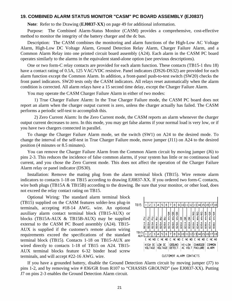
21
19. COMBINED ALARM STATUS MONITOR "CASM" PC BOARD ASSEMBLY (EJ0837)
Note: Refer to the Drawing (EJ0837-XX) on page 49 for additional information. Purpose: The Combined Alarm-Status Monitor (CASM) provides a comprehensive, cost-effective method to monitor the integrity of the battery charger and the dc bus. Description: The CASM combines the monitoring and alarm functions of the High-Low AC Voltage Alarm, High-Low DC Voltage Alarm, Ground Detection Relay Alarm, Charger Failure Alarm, and a Common Alarm Relay into one printed circuit board assembly (A24). Each alarm in the CASM PC board operates similarly to the alarms in the equivalent stand-alone option (see previous descriptions). One or two form-C relay contacts are provided for each alarm function. These contacts (TB15-1 thru 18) have a contact rating of 0.5A, 125 VAC/VDC resistive. Panel indicators (DS26-DS32) are provided for each alarm function except the Common Alarm. In addition, a front-panel push-to-test switch (SW20) checks the front panel indicators. SW20 tests only the CASM indicators. All relays reset automatically when the alarm condition is corrected. All alarm relays have a 15 second time delay, except the Charger Failure Alarm. You may operate the CASM Charger Failure Alarm in either of two modes: 1) True Charger Failure Alarm: In the True Charger Failure mode, the CASM PC board does not report an alarm when the charger output current is zero, unless the charger actually has failed. The CASM performs a periodic self-test to accomplish this. 2) Zero Current Alarm: In the Zero Current mode, the CASM reports an alarm whenever the charger output current decreases to zero. In this mode, you may get false alarms if your normal load is very low, or if you have two chargers connected in parallel. To change the Charger Failure Alarm mode, set the switch (SW1) on A24 to the desired mode. To change the interval of the self-test in True Charger Failure mode, move jumper (J11) on A24 to the desired position (4 minutes or 8.5 minutes). You can remove the Charger Failure Alarm from the Common Alarm circuit by moving jumper (J6) to pins 2-3. This reduces the incidence of false common alarms, if your system has little or no continuous load current, and you chose the Zero Current mode. This does not affect the operation of the Charger Failure Alarm relay or panel indicator (DS30). Installation: Remove the mating plug from the alarm terminal block (TB15). Wire remote alarm indicators to contacts 1-18 on TB15 according to drawing EJ0837-XX. If you ordered two form-C contacts, wire both plugs (TB15A & TB15B) according to the drawing. Be sure that your monitor, or other load, does not exceed the relay contact rating on TB15. Optional Wiring: The standard alarm terminal block (TB15) supplied on the CASM features solder-less plug-in terminals, accepting #18-14 AWG. wire. An optional auxiliary alarm contact terminal block (TB15-AUX) or blocks (TB15A-AUX & TB15B-AUX) may be supplied external to the CASM PC Board assembly (A24). TB15-AUX is supplied if the customer's remote alarm wiring requirements exceed the specifications of the standard terminal block (TB15). Contacts 1-18 on TB15-AUX are wired directly to contacts 1-18 of TB15 on A24. TB15-AUX terminal blocks feature 6-32 binder head screw terminals, and will accept #22-16 AWG. wire. If you have a grounded battery, disable the Ground Detection Alarm circuit by moving jumper (J7) to pins 1-2, and by removing wire # 836/GR from R107 to “CHASSIS GROUND” (see EJ0837-XX). Putting J7 on pins 2-3 enables the Ground Detection Alarm circuit.
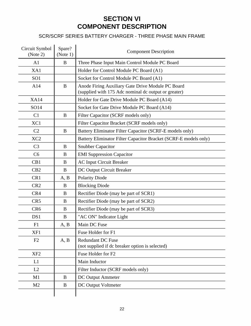
22
SECTION VI COMPONENT DESCRIPTION
SCR/SCRF SERIES BATTERY CHARGER - THREE PHASE MAIN FRAME
Circuit Symbol (Note 2)
Spare? (Note 1) Component Description
A1 B Three Phase Input Main Control Module PC Board
XA1 Holder for Control Module PC Board (A1)
SO1 Socket for Control Module PC Board (A1)
A14 B Anode Firing Auxiliary Gate Drive Module PC Board (supplied with 175 Adc nominal dc output or greater)
XA14 Holder for Gate Drive Module PC Board (A14)
SO14 Socket for Gate Drive Module PC Board (A14)
C1 B Filter Capacitor (SCRF models only)
XC1 Filter Capacitor Bracket (SCRF models only)
C2 B Battery Eliminator Filter Capacitor (SCRF-E models only)
XC2 Battery Eliminator Filter Capacitor Bracket (SCRF-E models only)
C3 B Snubber Capacitor
C6 B EMI Suppression Capacitor
CB1 B AC Input Circuit Breaker
CB2 B DC Output Circuit Breaker
CR1 A, B Polarity Diode
CR2 B Blocking Diode
CR4 B Rectifier Diode (may be part of SCR1)
CR5 B Rectifier Diode (may be part of SCR2)
CR6 B Rectifier Diode (may be part of SCR3)
DS1 B "AC ON" Indicator Light
F1 A, B Main DC Fuse
XF1 Fuse Holder for F1
F2 A, B Redundant DC Fuse (not supplied if dc breaker option is selected)
XF2 Fuse Holder for F2
L1 Main Inductor
L2 Filter Inductor (SCRF models only)
M1 B DC Output Ammeter
M2 B DC Output Voltmeter
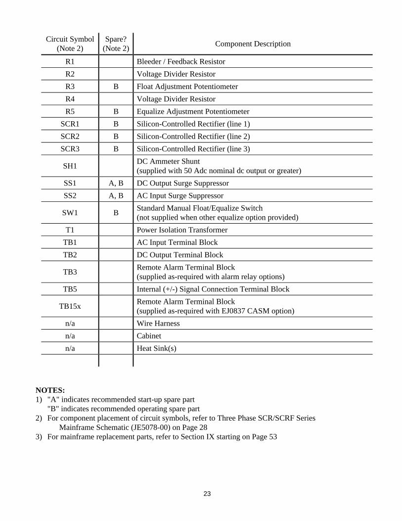
23
Circuit Symbol
(Note 2) Spare?
(Note 2) Component Description
R1 Bleeder / Feedback Resistor
R2 Voltage Divider Resistor
R3 B Float Adjustment Potentiometer
R4 Voltage Divider Resistor
R5 B Equalize Adjustment Potentiometer
SCR1 B Silicon-Controlled Rectifier (line 1)
SCR2 B Silicon-Controlled Rectifier (line 2)
SCR3 B Silicon-Controlled Rectifier (line 3)
SH1 DC Ammeter Shunt (supplied with 50 Adc nominal dc output or greater)
SS1 A, B DC Output Surge Suppressor
SS2 A, B AC Input Surge Suppressor
SW1 B Standard Manual Float/Equalize Switch (not supplied when other equalize option provided)
T1 Power Isolation Transformer
TB1 AC Input Terminal Block
TB2 DC Output Terminal Block
TB3 Remote Alarm Terminal Block (supplied as-required with alarm relay options)
TB5 Internal (+/-) Signal Connection Terminal Block
TB15x Remote Alarm Terminal Block (supplied as-required with EJ0837 CASM option)
n/a Wire Harness
n/a Cabinet
n/a Heat Sink(s)
NOTES: 1) "A" indicates recommended start-up spare part "B" indicates recommended operating spare part 2) For component placement of circuit symbols, refer to Three Phase SCR/SCRF Series
Mainframe Schematic (JE5078-00) on Page 28 3) For mainframe replacement parts, refer to Section IX starting on Page 53
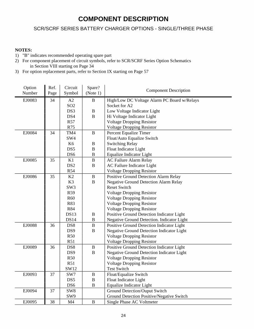
24
COMPONENT DESCRIPTION
SCR/SCRF SERIES BATTERY CHARGER OPTIONS - SINGLE/THREE PHASE
NOTES: 1) "B" indicates recommended operating spare part 2) For component placement of circuit symbols, refer to SCR/SCRF Series Option Schematics
in Section VIII starting on Page 34 3) For option replacement parts, refer to Section IX starting on Page 57
Option Number
Ref. Page
Circuit Symbol
Spare? (Note 1) Component Description
EJ0083 34 A2 B High/Low DC Voltage Alarm PC Board w/Relays SO2 Socket for A2 DS3 B Low Voltage Indicator Light DS4 B Hi Voltage Indicator Light R57 Voltage Dropping Resistor R75 Voltage Dropping Resistor
EJ0084 34 TM4 B Percent Equalize Timer SW4 Float/Auto Equalize Switch K6 B Switching Relay DS5 B Float Indicator Light DS6 B Equalize Indicator Light
EJ0085 35 K1 B AC Failure Alarm Relay DS2 B AC Failure Indicator Light R54 Voltage Dropping Resistor
EJ0086 35 K2 B Positive Ground Detection Alarm Relay K3 B Negative Ground Detection Alarm Relay SW3 Reset Switch R59 Voltage Dropping Resistor R60 Voltage Dropping Resistor R83 Voltage Dropping Resistor R84 Voltage Dropping Resistor DS13 B Positive Ground Detection Indicator Light DS14 B Negative Ground Detection. Indicator Light
EJ0088 36 DS8 B Positive Ground Detection Indicator Light DS9 B Negative Ground Detection Indicator Light R50 Voltage Dropping Resistor R51 Voltage Dropping Resistor
EJ0089 36 DS8 B Positive Ground Detection Indicator Light DS9 B Negative Ground Detection Indicator Light R50 Voltage Dropping Resistor R51 Voltage Dropping Resistor SW12 Test Switch
EJ0093 37 SW7 B Float/Equalize Switch DS5 B Float Indicator Light DS6 B Equalize Indicator Light
EJ0094 37 SW8 Ground Detection/Ouput Switch SW9 Ground Detection Positive/Negative Switch
EJ0095 38 M4 B Single Phase AC Voltmeter
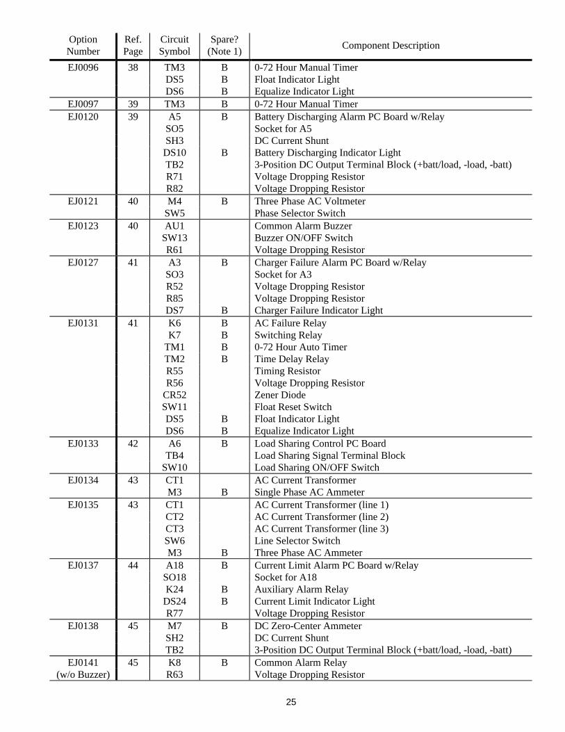
25
Option Number
Ref. Page
Circuit Symbol
Spare? (Note 1) Component Description
EJ0096 38 TM3 B 0-72 Hour Manual Timer DS5 B Float Indicator Light DS6 B Equalize Indicator Light
EJ0097 39 TM3 B 0-72 Hour Manual Timer EJ0120 39 A5 B Battery Discharging Alarm PC Board w/Relay
SO5 Socket for A5 SH3 DC Current Shunt DS10 B Battery Discharging Indicator Light TB2 3-Position DC Output Terminal Block (+batt/load, -load, -batt) R71 Voltage Dropping Resistor R82 Voltage Dropping Resistor
EJ0121 40 M4 B Three Phase AC Voltmeter SW5 Phase Selector Switch
EJ0123 40 AU1 Common Alarm Buzzer SW13 Buzzer ON/OFF Switch R61 Voltage Dropping Resistor
EJ0127 41 A3 B Charger Failure Alarm PC Board w/Relay SO3 Socket for A3 R52 Voltage Dropping Resistor R85 Voltage Dropping Resistor DS7 B Charger Failure Indicator Light
EJ0131 41 K6 B AC Failure Relay K7 B Switching Relay TM1 B 0-72 Hour Auto Timer TM2 B Time Delay Relay R55 Timing Resistor R56 Voltage Dropping Resistor CR52 Zener Diode SW11 Float Reset Switch DS5 B Float Indicator Light DS6 B Equalize Indicator Light
EJ0133 42 A6 B Load Sharing Control PC Board TB4 Load Sharing Signal Terminal Block SW10 Load Sharing ON/OFF Switch
EJ0134 43 CT1 AC Current Transformer M3 B Single Phase AC Ammeter
EJ0135 43 CT1 AC Current Transformer (line 1) CT2 AC Current Transformer (line 2) CT3 AC Current Transformer (line 3) SW6 Line Selector Switch M3 B Three Phase AC Ammeter
EJ0137 44 A18 B Current Limit Alarm PC Board w/Relay SO18 Socket for A18 K24 B Auxiliary Alarm Relay DS24 B Current Limit Indicator Light R77 Voltage Dropping Resistor
EJ0138 45 M7 B DC Zero-Center Ammeter SH2 DC Current Shunt TB2 3-Position DC Output Terminal Block (+batt/load, -load, -batt)
EJ0141 45 K8 B Common Alarm Relay (w/o Buzzer) R63 Voltage Dropping Resistor
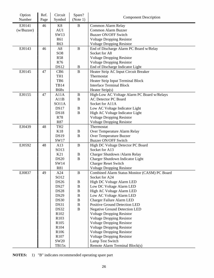
26
Option Number
Ref. Page
Circuit Symbol
Spare? (Note 1) Component Description
EJ0141 46 K8 B Common Alarm Relay (w/Buzzer) AU1 Common Alarm Buzzer
SW13 Buzzer ON/OFF Switch R61 Voltage Dropping Resistor R63 Voltage Dropping Resistor
EJ0143 46 A8 B End of Discharge Alarm PC Board w/Relay SO8 Socket for A8 R58 Voltage Dropping Resistor R76 Voltage Dropping Resistor DS12 B End of Discharge Indicator Light
EJ0145 47 CB6 B Heater Strip AC Input Circuit Breaker TH1 Thermostat TB6 Heater Strip Input Terminal Block TB14 Interface Terminal Block R68x Heater Strip(s)
EJ0155 47 A11A B High-Low AC Voltage Alarm PC Board w/Relays A11B B AC Detector PC Board SO11A Socket for A11A DS17 B Low AC Voltage Indicator Light DS18 B High AC Voltage Indicator Light R78 Voltage Dropping Resistor R87 Voltage Dropping Resistor
EJ0439 48 TH2 Thermostat K18 B Over Temperature Alarm Relay DS19 B Over Temperature Buzzer SW17 Buzzer ON/OFF Switch
EJ0592 48 A13 B High DC Voltage Detector PC Board SO13 Socket for A13 K21 B Charger Shutdown /Alarm Relay DS20 B Charger Shutdown Indicator Light SW14 Charger Reset Switch R81 Voltage Dropping Resistor
EJ0837 49 A24 B Combined Alarm Status Monitor (CASM) PC Board SO12 Socket for A24 DS26 B High DC Voltage Alarm LED DS27 B Low DC Voltage Alarm LED DS28 B High AC Voltage Alarm LED DS29 B Low AC Voltage Alarm LED DS30 B Charger Failure Alarm LED DS31 B Positive Ground Detection LED DS32 B Negative Ground Detection LED R102 Voltage Dropping Resistor R103 Voltage Dropping Resistor R105 Voltage Dropping Resistor R104 Voltage Dropping Resistor R106 Voltage Dropping Resistor R107 Voltage Dropping Resistor SW20 Lamp Test Switch TB15x Remote Alarm Terminal Block(s)
NOTES: 1) "B" indicates recommended operating spare part
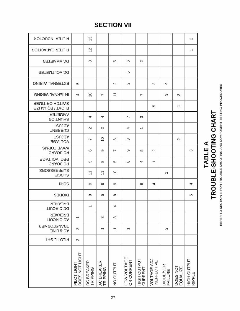
PILOT LIGHT
AC & LINE TRANSFORMER
AC CIRCUIT BREKAER
DC CIRCUIT BREAKER
DIODES
SCRs
SURGE SUPPRESSORS
PC BOARD REG. VOLTAGE
PC BOARD WAVE FORMS
VOLTAGE ADJUST
CURRENT ADJUST
SHUNT OR AMMETER
FLOAT / EQUALIZE SWITCH OR TIMER
INTERNAL WIRING
EXTERNAL WIRING
DC VOLTMETER
DC AMMETER
FILTER CAPACITOR
FILTER INDUCTOR
PIL
OT
LIG
HT
D
OE
S N
OT
LIG
HT
2
3 1
4 5
DC
BR
EA
KE
R
TR
IPP
ING
1 8
9 11
5
6 7
2 4
10
3
12
13
AC
BR
EA
KE
R
TR
IPP
ING
1 3
5
6 11
8
9 10
2
4
7
NO
OU
TP
UT
1 3
4 8
9 10
5
7 6
11
2
5
LOW
VO
LTA
GE
O
R C
UR
RE
NT
1
8 9
3 4
7
2
5 6
HIG
H O
UT
PU
T
CU
RR
EN
T
6
4
5
1 3
7
2
VO
LTA
GE
AD
J.
INE
FF
EC
TIV
E
4
1
2
5
3
DIO
DE
/SC
R
FA
ILU
RE
2
1
3 4
DO
ES
NO
T
EQ
UA
LIZ
E
2
1 3
27
HIG
H O
UT
PU
T
RIP
PLE
5
4
3
1 2
SECTION VII
TAB
LE A
T
RO
UB
LE
-SH
OO
TIN
G C
HA
RT
RE
FE
R T
O S
EC
TIO
N II
I FO
R T
RO
UB
LE S
HO
OT
ING
AN
D C
OM
PO
NE
NT
TE
ST
ING
PR
OC
ED
UR
ES
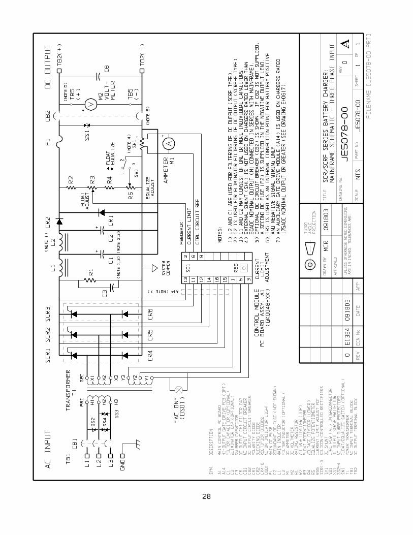
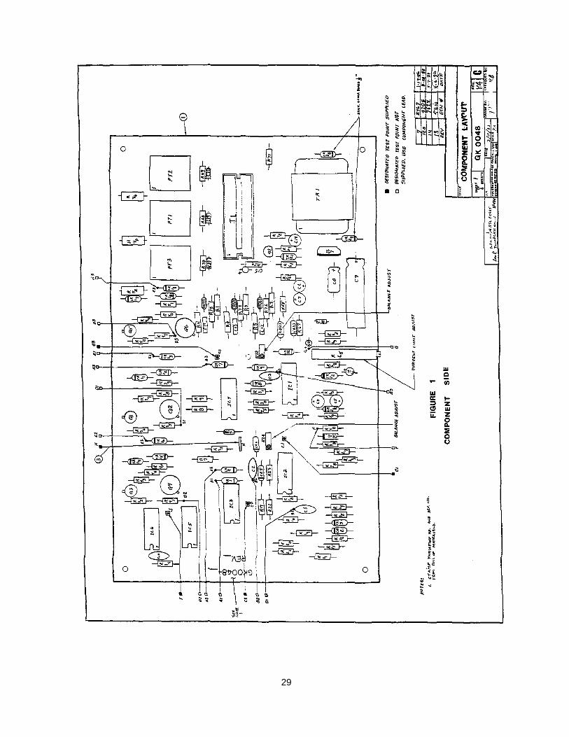
29
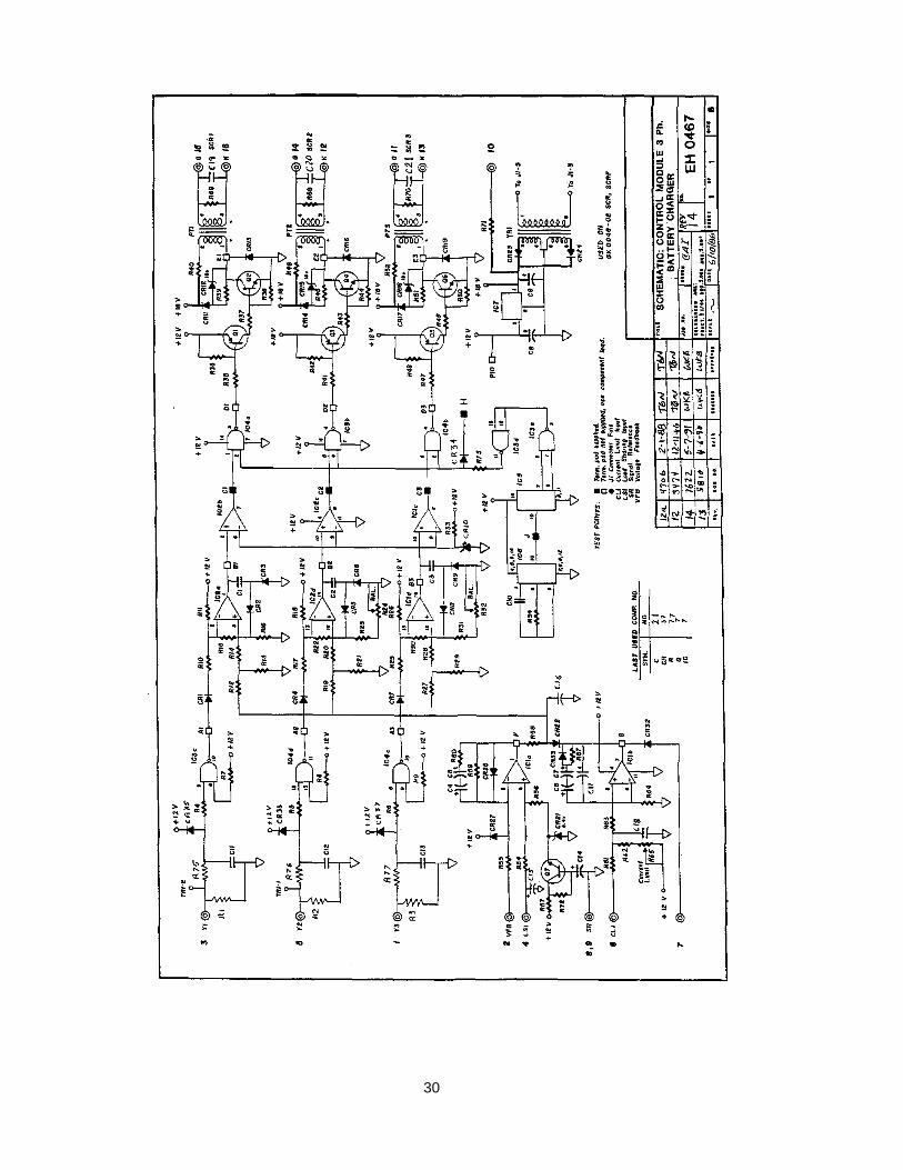
30
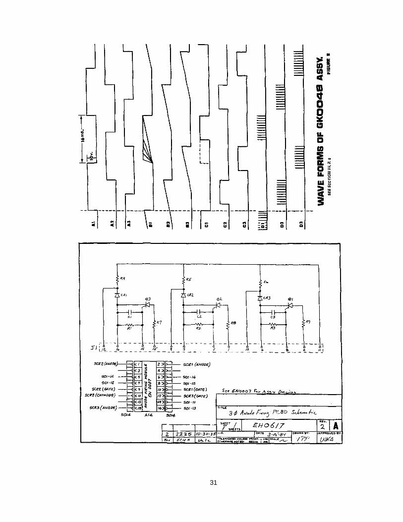
31
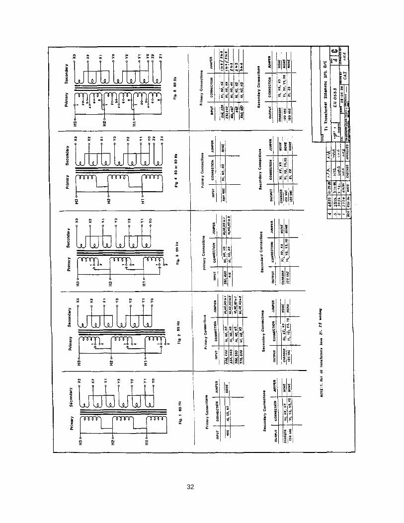
32
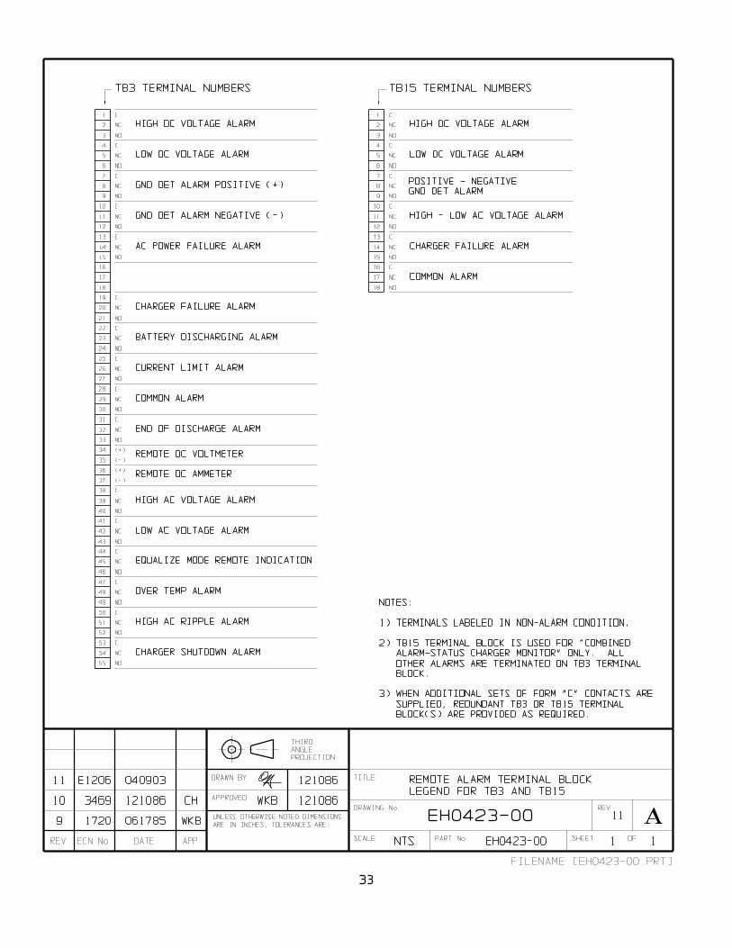
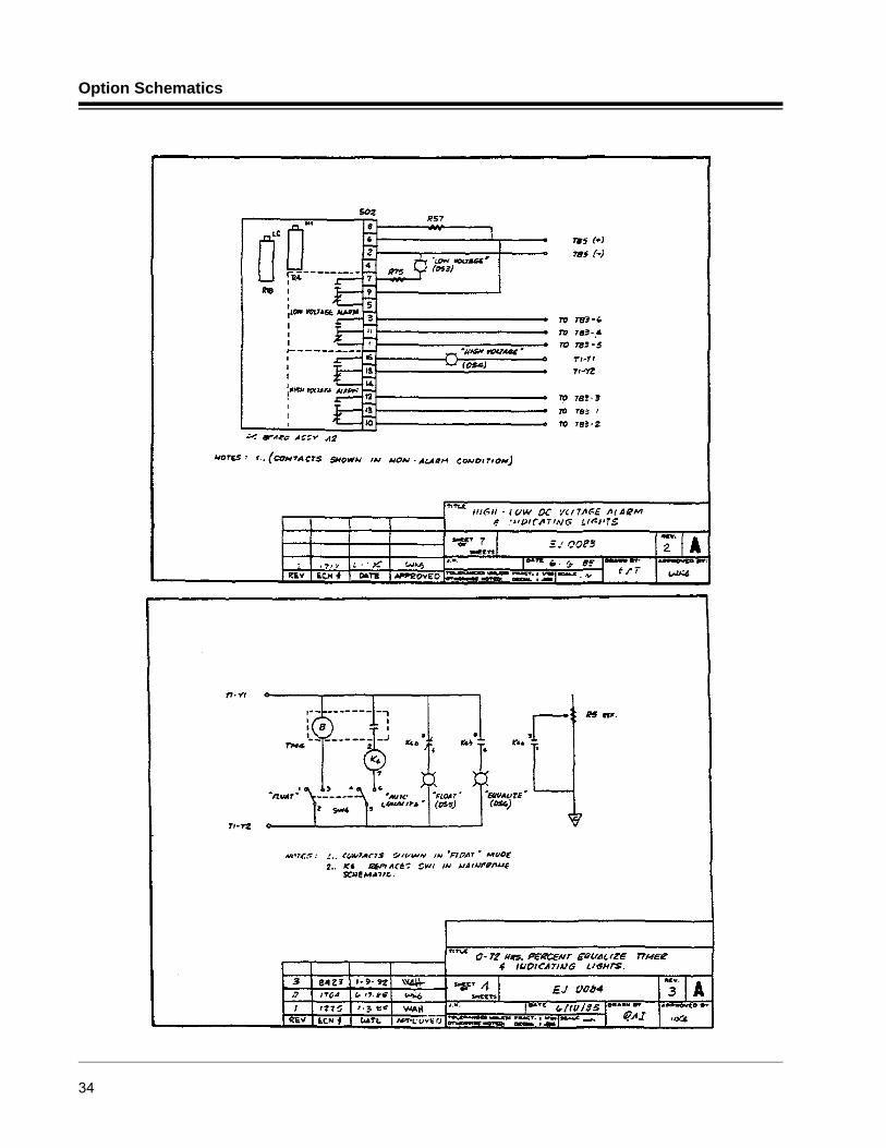
Option Schematics
34
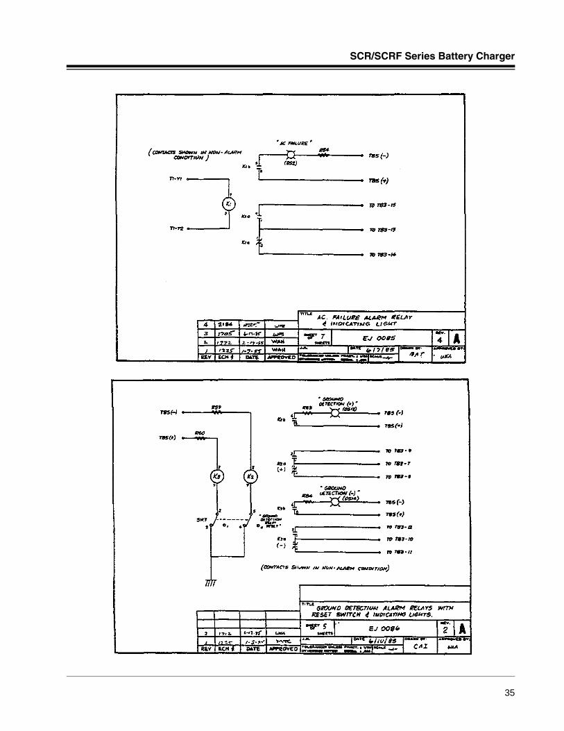
SCR/SCRF Series Battery Charger
35
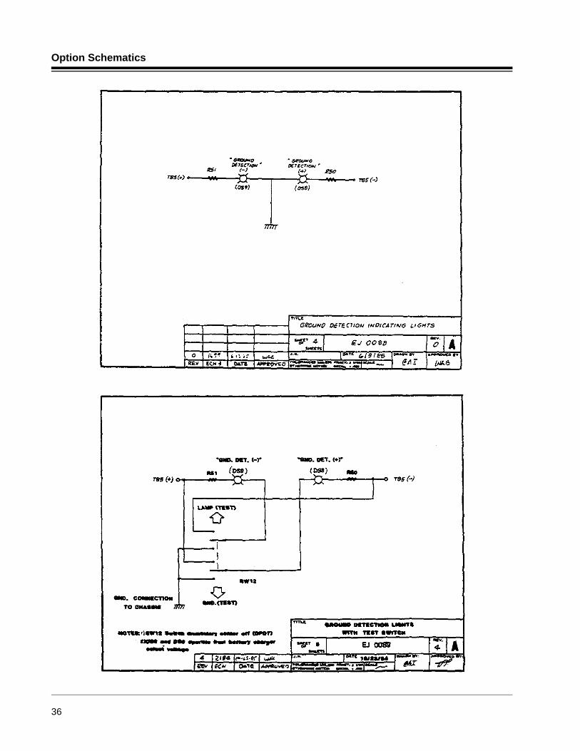
Option Schematics
36
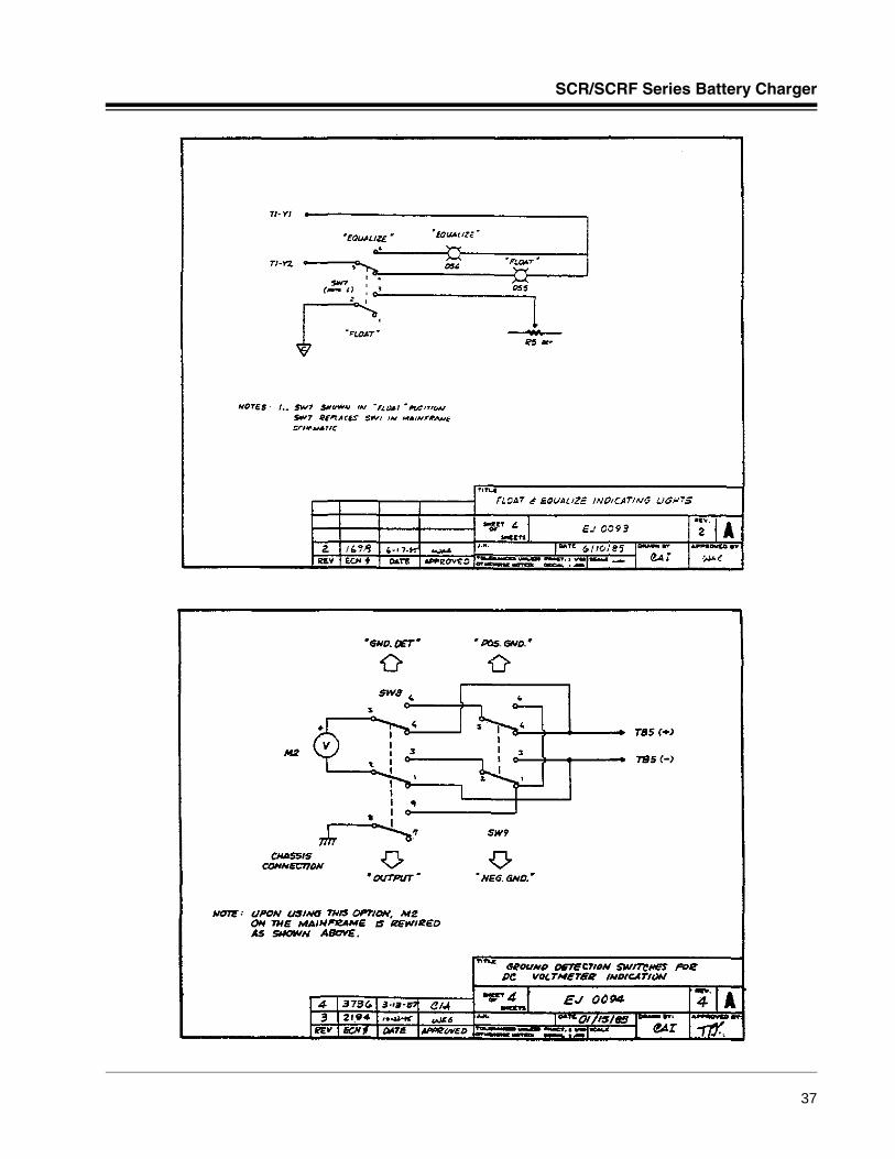
SCR/SCRF Series Battery Charger
37
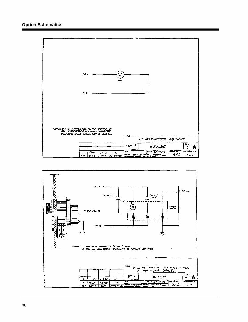
Option Schematics
38
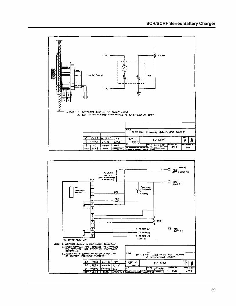
SCR/SCRF Series Battery Charger
39
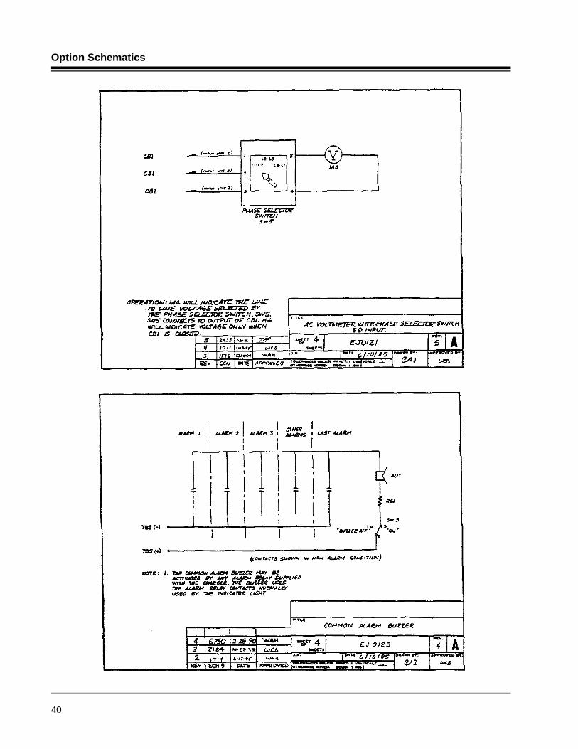
Option Schematics
40
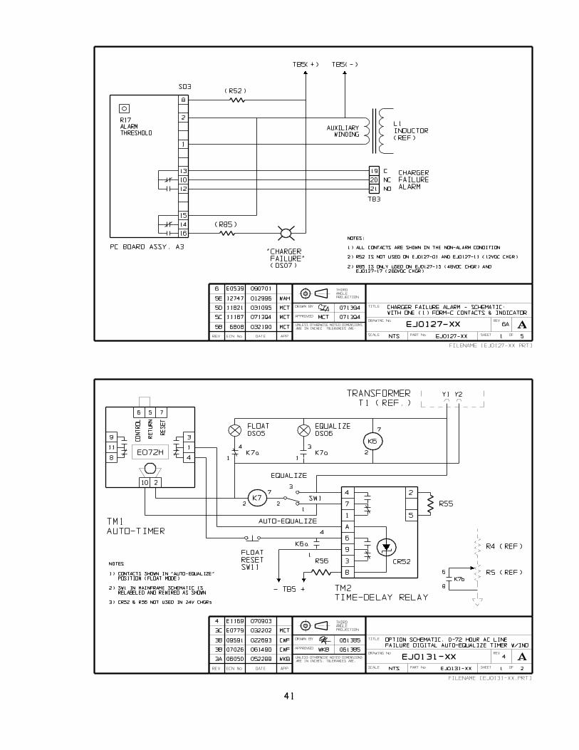
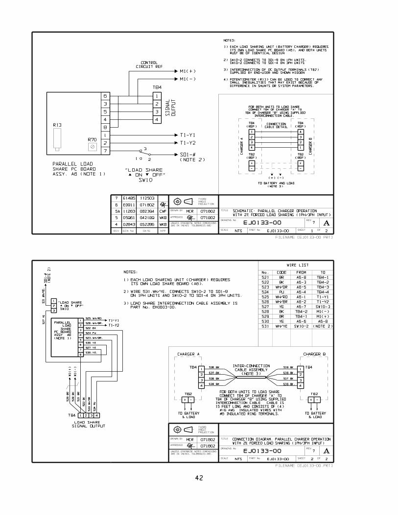
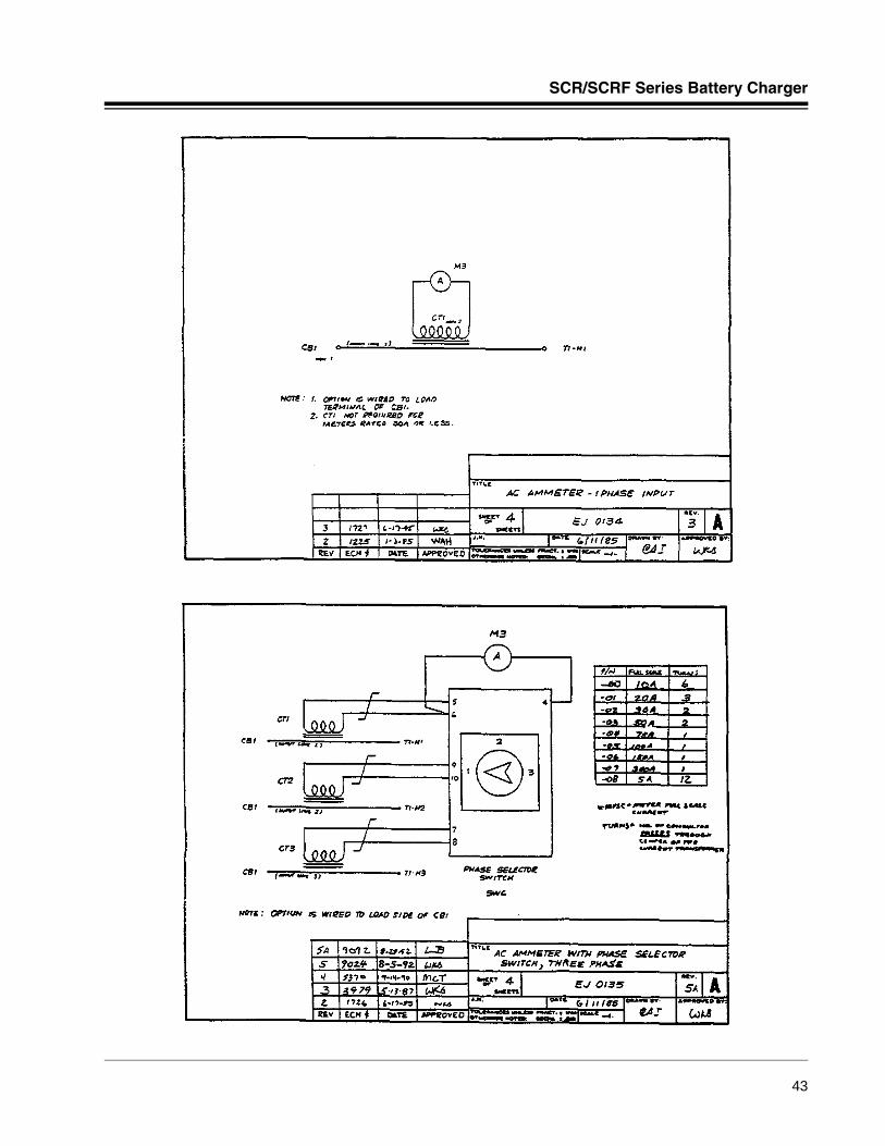
SCR/SCRF Series Battery Charger
43
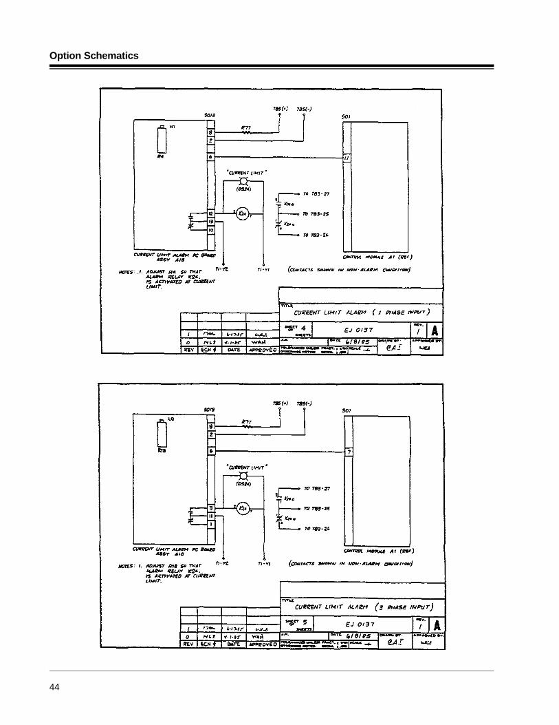
Option Schematics
44
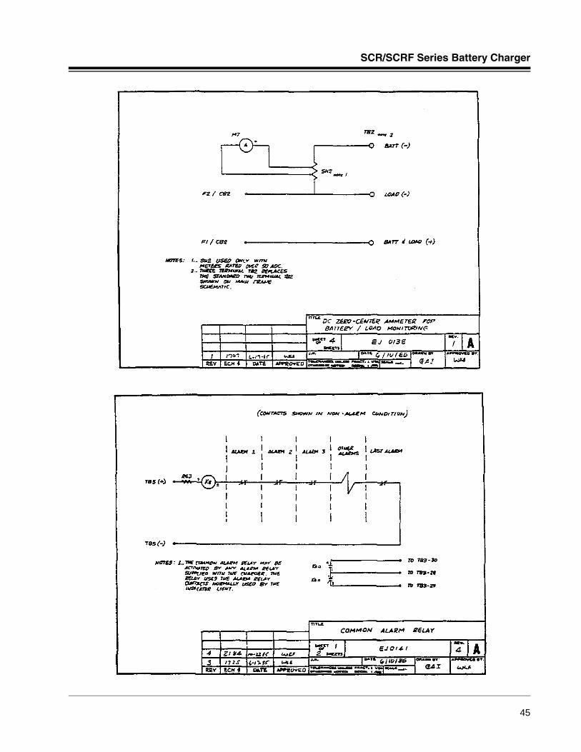
SCR/SCRF Series Battery Charger
45
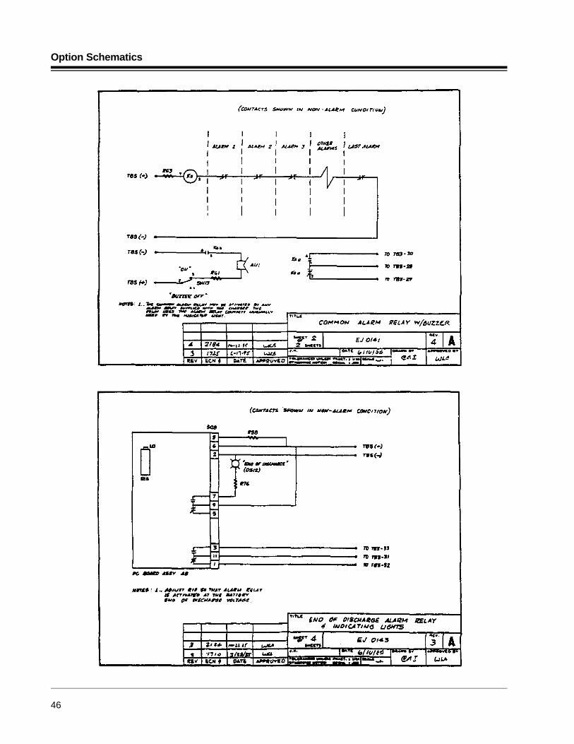
Option Schematics
46
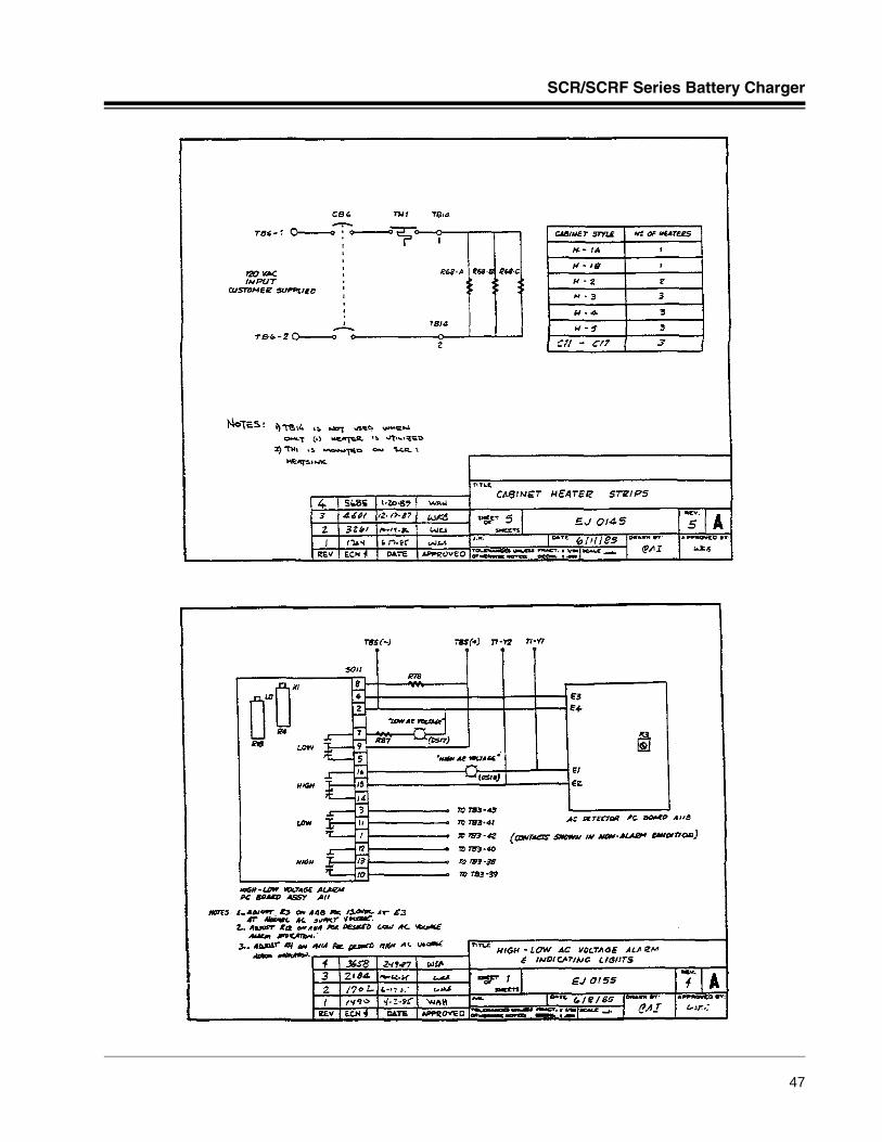
SCR/SCRF Series Battery Charger
47
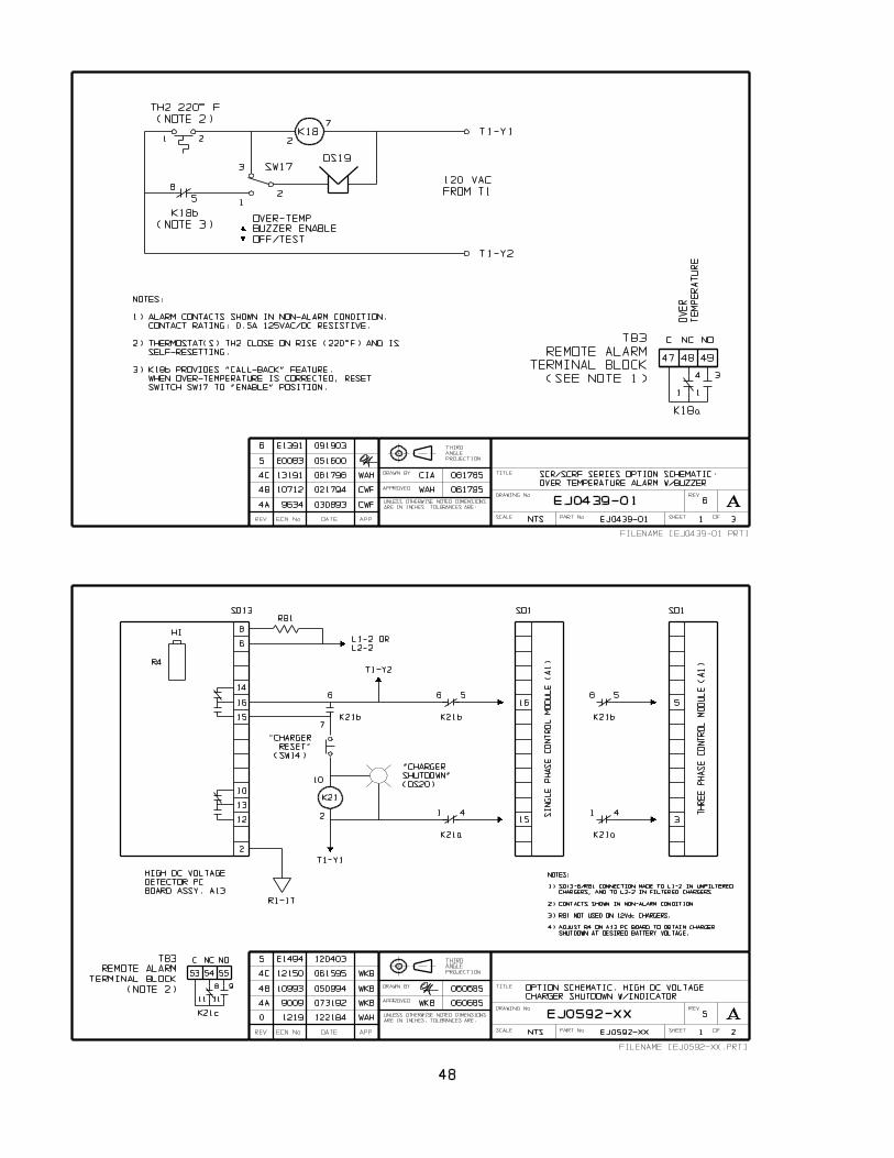
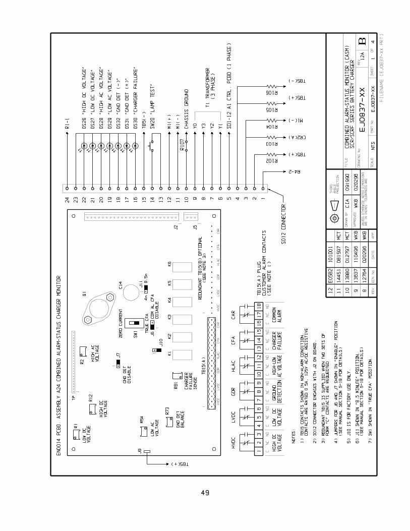
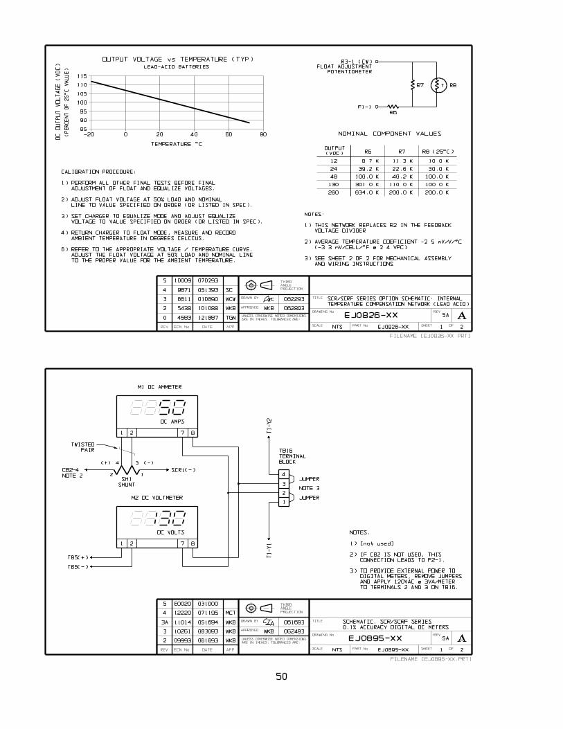
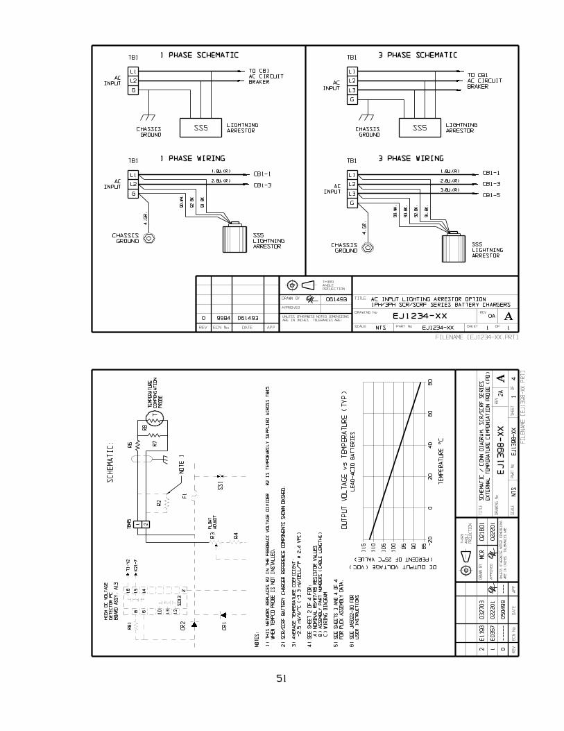
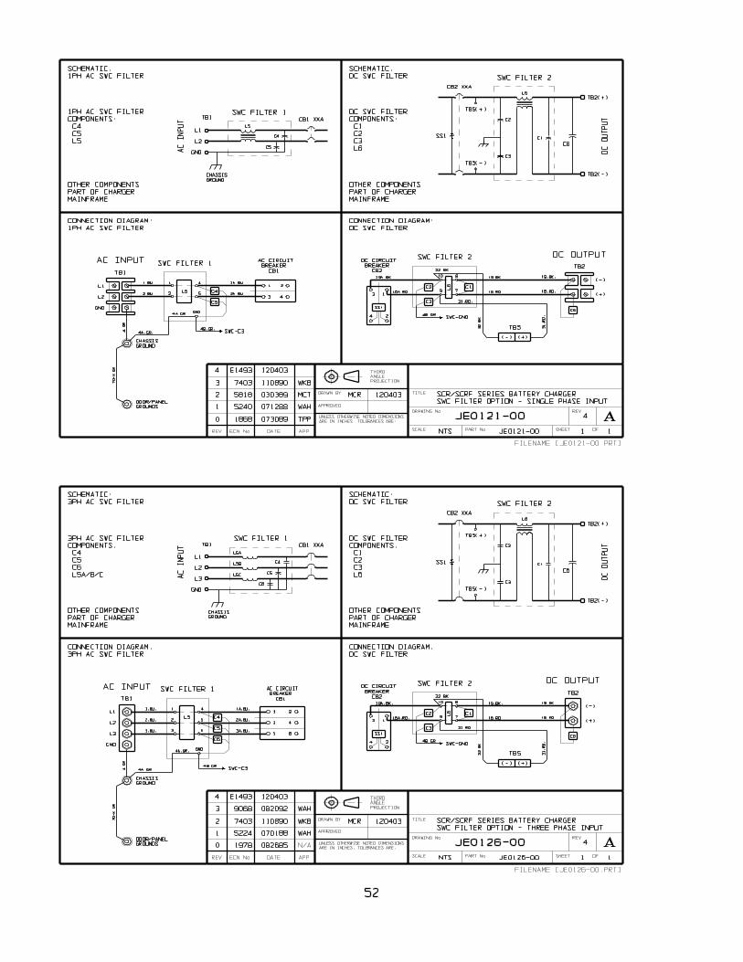
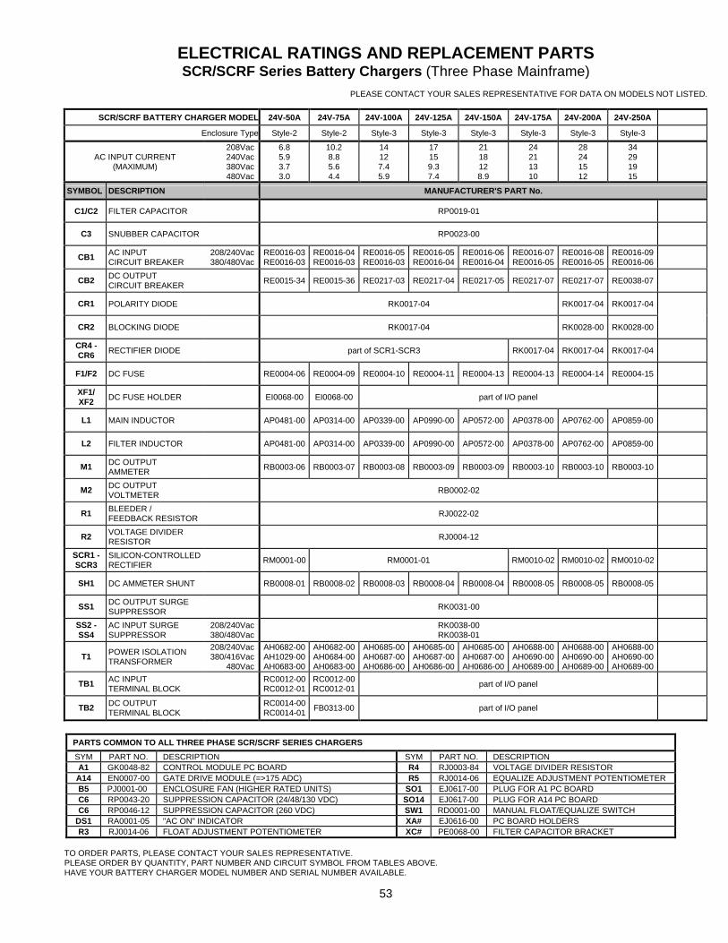
53
ELECTRICAL RATINGS AND REPLACEMENT PARTS SCR/SCRF Series Battery Chargers (Three Phase Mainframe)
PLEASE CONTACT YOUR SALES REPRESENTATIVE FOR DATA ON MODELS NOT LISTED.
SCR/SCRF BATTERY CHARGER MODEL 24V-50A 24V-75A 24V-100A 24V-125A 24V-150A 24V-175A 24V-200A 24V-250A
Enclosure Type Style-2 Style-2 Style-3 Style-3 Style-3 Style-3 Style-3 Style-3
AC INPUT CURRENT (MAXIMUM)
208Vac 240Vac 380Vac 480Vac
6.8 5.9 3.7 3.0
10.2 8.8 5.6 4.4
14 12 7.4 5.9
17 15 9.3 7.4
21 18 12 8.9
24 21 13 10
28 24 15 12
34 29 19 15
SYMBOL DESCRIPTION MANUFACTURER'S PART No.
C1/C2 FILTER CAPACITOR RP0019-01
C3 SNUBBER CAPACITOR RP0023-00
CB1 AC INPUT CIRCUIT BREAKER
208/240Vac 380/480Vac
RE0016-03 RE0016-03
RE0016-04 RE0016-03
RE0016-05 RE0016-03
RE0016-05 RE0016-04
RE0016-06 RE0016-04
RE0016-07 RE0016-05
RE0016-08 RE0016-05
RE0016-09 RE0016-06
CB2 DC OUTPUT CIRCUIT BREAKER RE0015-34 RE0015-36 RE0217-03 RE0217-04 RE0217-05 RE0217-07 RE0217-07 RE0038-07
CR1 POLARITY DIODE RK0017-04 RK0017-04 RK0017-04
CR2 BLOCKING DIODE RK0017-04 RK0028-00 RK0028-00
CR4 - CR6 RECTIFIER DIODE part of SCR1-SCR3 RK0017-04 RK0017-04 RK0017-04
F1/F2 DC FUSE RE0004-06 RE0004-09 RE0004-10 RE0004-11 RE0004-13 RE0004-13 RE0004-14 RE0004-15
XF1/ XF2 DC FUSE HOLDER EI0068-00 EI0068-00 part of I/O panel
L1 MAIN INDUCTOR AP0481-00 AP0314-00 AP0339-00 AP0990-00 AP0572-00 AP0378-00 AP0762-00 AP0859-00
L2 FILTER INDUCTOR AP0481-00 AP0314-00 AP0339-00 AP0990-00 AP0572-00 AP0378-00 AP0762-00 AP0859-00
M1 DC OUTPUT AMMETER RB0003-06 RB0003-07 RB0003-08 RB0003-09 RB0003-09 RB0003-10 RB0003-10 RB0003-10
M2 DC OUTPUT VOLTMETER RB0002-02
R1 BLEEDER / FEEDBACK RESISTOR RJ0022-02
R2 VOLTAGE DIVIDER RESISTOR RJ0004-12
SCR1 - SCR3
SILICON-CONTROLLED RECTIFIER RM0001-00 RM0001-01 RM0010-02 RM0010-02 RM0010-02
SH1 DC AMMETER SHUNT RB0008-01 RB0008-02 RB0008-03 RB0008-04 RB0008-04 RB0008-05 RB0008-05 RB0008-05
SS1 DC OUTPUT SURGE SUPPRESSOR RK0031-00
SS2 - SS4
AC INPUT SURGE SUPPRESSOR
208/240Vac 380/480Vac
RK0038-00 RK0038-01
T1 POWER ISOLATION TRANSFORMER
208/240Vac 380/416Vac
480Vac
AH0682-00 AH1029-00 AH0683-00
AH0682-00 AH0684-00 AH0683-00
AH0685-00 AH0687-00 AH0686-00
AH0685-00 AH0687-00 AH0686-00
AH0685-00 AH0687-00 AH0686-00
AH0688-00 AH0690-00 AH0689-00
AH0688-00 AH0690-00 AH0689-00
AH0688-00 AH0690-00 AH0689-00
TB1 AC INPUT TERMINAL BLOCK
RC0012-00 RC0012-01
RC0012-00 RC0012-01 part of I/O panel
TB2 DC OUTPUT TERMINAL BLOCK
RC0014-00 RC0014-01 FB0313-00 part of I/O panel
PARTS COMMON TO ALL THREE PHASE SCR/SCRF SERIES CHARGERS
SYM PART NO. DESCRIPTION SYM PART NO. DESCRIPTION A1 GK0048-82 CONTROL MODULE PC BOARD R4 RJ0003-84 VOLTAGE DIVIDER RESISTOR A14 EN0007-00 GATE DRIVE MODULE (=>175 ADC) R5 RJ0014-06 EQUALIZE ADJUSTMENT POTENTIOMETER B5 PJ0001-00 ENCLOSURE FAN (HIGHER RATED UNITS) SO1 EJ0617-00 PLUG FOR A1 PC BOARD C6 RP0043-20 SUPPRESSION CAPACITOR (24/48/130 VDC) SO14 EJ0617-00 PLUG FOR A14 PC BOARD C6 RP0046-12 SUPPRESSION CAPACITOR (260 VDC) SW1 RD0001-00 MANUAL FLOAT/EQUALIZE SWITCH
DS1 RA0001-05 "AC ON" INDICATOR XA# EJ0616-00 PC BOARD HOLDERS R3 RJ0014-06 FLOAT ADJUSTMENT POTENTIOMETER XC# PE0068-00 FILTER CAPACITOR BRACKET
TO ORDER PARTS, PLEASE CONTACT YOUR SALES REPRESENTATIVE. PLEASE ORDER BY QUANTITY, PART NUMBER AND CIRCUIT SYMBOL FROM TABLES ABOVE. HAVE YOUR BATTERY CHARGER MODEL NUMBER AND SERIAL NUMBER AVAILABLE.
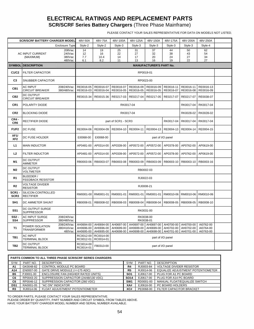
54
ELECTRICAL RATINGS AND REPLACEMENT PARTS SCR/SCRF Series Battery Chargers (Three Phase Mainframe)
PLEASE CONTACT YOUR SALES REPRESENTATIVE FOR DATA ON MODELS NOT LISTED.
SCR/SCRF BATTERY CHARGER MODEL 48V-50A 48V-75A 48V-100A 48V-125A 48V-150A 48V-175A 48V-200A 48V-250A
Enclosure Type Style-2 Style-2 Style-3 Style-3 Style-3 Style-3 Style-3 Style-4
AC INPUT CURRENT (MAXIMUM)
208Vac 240Vac 380Vac 480Vac
14 12 7.7 6.1
19 16
10.4 8.2
25 22 14 11
31 27 17 13
37 32 20 16
44 38 24 19
50 43 27 22
62 54 34 27
SYMBOL DESCRIPTION MANUFACTURER'S PART No.
C1/C2 FILTER CAPACITOR RP0019-01
C3 SNUBBER CAPACITOR RP0023-00
CB1 AC INPUT CIRCUIT BREAKER
208/240Vac 380/480Vac
RE0016-05 RE0016-03
RE0016-07 RE0016-04
RE0016-07 RE0016-05
RE0016-09 RE0016-05
RE0016-09 RE0016-05
RE0016-11 RE0016-07
RE0016-11 RE0016-08
RE0016-13 RE0016-09
CB2 DC OUTPUT CIRCUIT BREAKER RE0015-34 RE0015-36 RE0217-03 RE0217-04 RE0217-05 RE0217-07 RE0217-07 RE0038-07
CR1 POLARITY DIODE RK0017-04 RK0017-04 RK0017-04
CR2 BLOCKING DIODE RK0017-04 RK0028-02 RK0028-02
CR4 - CR6 RECTIFIER DIODE part of SCR1 - SCR3 RK0017-04 RK0017-04 RK0017-04
F1/F2 DC FUSE RE0004-06 RE0004-09 RE0004-10 RE0004-11 RE0004-13 RE0004-13 RE0004-14 RE0004-15
XF1/ XF2 DC FUSE HOLDER EI0068-00 EI0068-00 part of I/O panel
L1 MAIN INDUCTOR AP0481-00 AP0314-00 AP0339-00 AP0572-00 AP0572-00 AP0378-00 AP0762-00 AP0619-00
L2 FILTER INDUCTOR AP0481-00 AP0314-00 AP0339-00 AP0572-00 AP0572-00 AP0378-00 AP0762-00 AP0619-00
M1 DC OUTPUT AMMETER RB0003-06 RB0003-07 RB0003-08 RB0003-09 RB0003-09 RB0003-10 RB0003-10 RB0003-16
M2 DC OUTPUT VOLTMETER RB0002-03
R1 BLEEDER / FEEDBACK RESISTOR RJ0022-03
R2 VOLTAGE DIVIDER RESISTOR RJ0008-21
SCR1 - SCR3
SILICON-CONTROLLED RECTIFIER RM0001-00 RM0001-01 RM0001-01 RM0001-01 RM0001-01 RM0010-06 RM0010-06 RM0010-06
SH1 DC AMMETER SHUNT RB0008-01 RB0008-02 RB0008-03 RB0008-04 RB0008-04 RB0008-05 RB0008-05 RB0008-10
SS1 DC OUTPUT SURGE SUPPRESSOR RK0031-00
SS2 - SS4
AC INPUT SURGE SUPPRESSOR
208/240Vac 380/480Vac
RK0038-00 RK0038-01
T1 POWER ISOLATION TRANSFORMER
208/240Vac 380/416Vac
480Vac
AH0694-00 AH0696-00 AH0695-00
AH0694-00 AH0696-00 AH0695-00
AH0697-00 AH0699-00 AH0698-00
AH0697-00 AH0699-00 AH0698-00
AH0697-00 AH0699-00 AH0698-00
AH0700-00 AH0702-00 AH0701-00
AH0700-00 AH0702-00 AH0701-00
AI0762-00 AI0764-00 AI0763-00
TB1 AC INPUT TERMINAL BLOCK
RC0012-00 RC0012-01
RC0014-00 RC0014-01 part of I/O panel
TB2 DC OUTPUT TERMINAL BLOCK
RC0014-00 RC0014-01 FB0313-00 part of I/O panel
PARTS COMMON TO ALL THREE PHASE SCR/SCRF SERIES CHARGERS
SYM PART NO. DESCRIPTION SYM PART NO. DESCRIPTION A1 GK0048-82 CONTROL MODULE PC BOARD R4 RJ0003-84 VOLTAGE DIVIDER RESISTOR A14 EN0007-00 GATE DRIVE MODULE (=>175 ADC) R5 RJ0014-06 EQUALIZE ADJUSTMENT POTENTIOMETER B5 PJ0001-00 ENCLOSURE FAN (HIGHER RATED UNITS) SO1 EJ0617-00 PLUG FOR A1 PC BOARD C6 RP0043-20 SUPPRESSION CAPACITOR (24/48/130 VDC) SO14 EJ0617-00 PLUG FOR A14 PC BOARD C6 RP0046-12 SUPPRESSION CAPACITOR (260 VDC) SW1 RD0001-00 MANUAL FLOAT/EQUALIZE SWITCH
DS1 RA0001-05 "AC ON" INDICATOR XA# EJ0616-00 PC BOARD HOLDERS R3 RJ0014-06 FLOAT ADJUSTMENT POTENTIOMETER XC# PE0068-00 FILTER CAPACITOR BRACKET
TO ORDER PARTS, PLEASE CONTACT YOUR SALES REPRESENTATIVE. PLEASE ORDER BY QUANTITY, PART NUMBER AND CIRCUIT SYMBOL FROM TABLES ABOVE. HAVE YOUR BATTERY CHARGER MODEL NUMBER AND SERIAL NUMBER AVAILABLE.
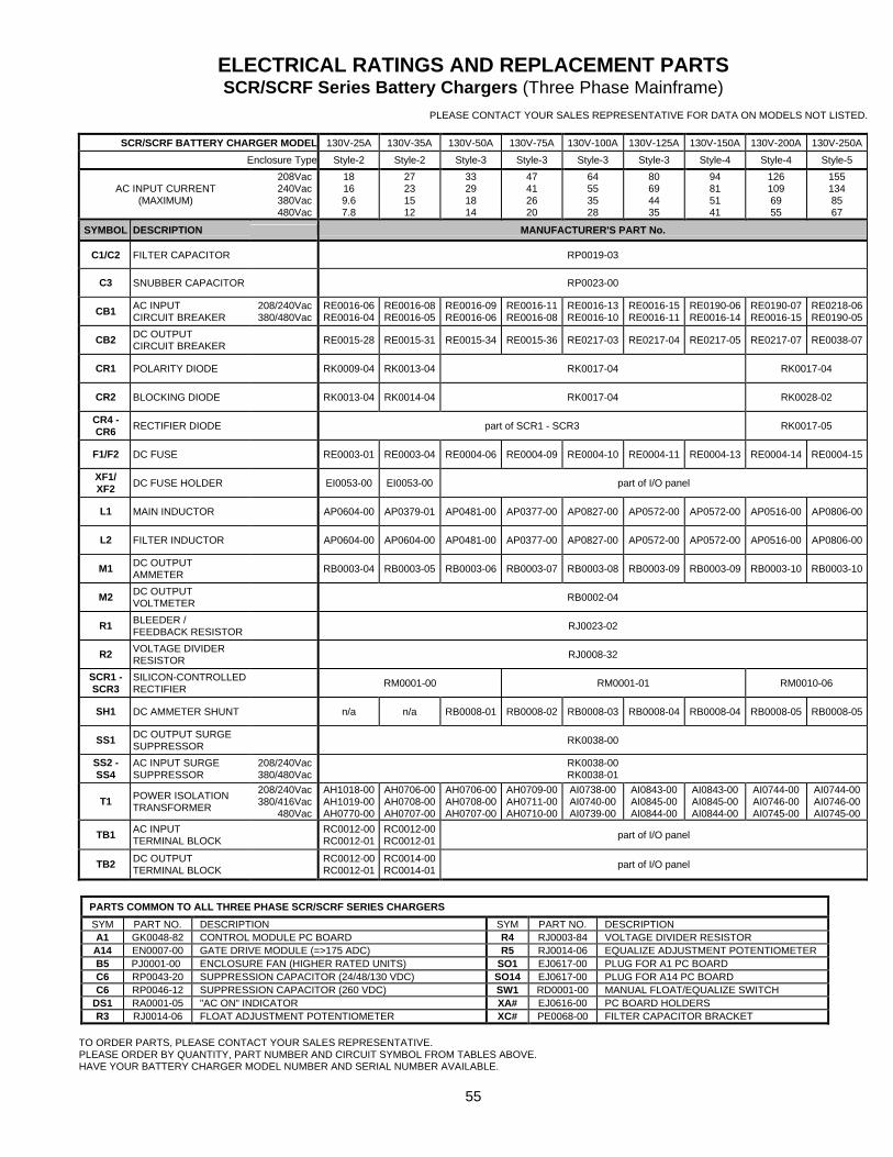
55
ELECTRICAL RATINGS AND REPLACEMENT PARTS SCR/SCRF Series Battery Chargers (Three Phase Mainframe)
PLEASE CONTACT YOUR SALES REPRESENTATIVE FOR DATA ON MODELS NOT LISTED.
SCR/SCRF BATTERY CHARGER MODEL 130V-25A 130V-35A 130V-50A 130V-75A 130V-100A 130V-125A 130V-150A 130V-200A 130V-250A
Enclosure Type Style-2 Style-2 Style-3 Style-3 Style-3 Style-3 Style-4 Style-4 Style-5
AC INPUT CURRENT (MAXIMUM)
208Vac 240Vac 380Vac 480Vac
18 16 9.6 7.8
27 23 15 12
33 29 18 14
47 41 26 20
64 55 35 28
80 69 44 35
94 81 51 41
126 109 69 55
155 134 85 67
SYMBOL DESCRIPTION MANUFACTURER'S PART No.
C1/C2 FILTER CAPACITOR RP0019-03
C3 SNUBBER CAPACITOR RP0023-00
CB1 AC INPUT CIRCUIT BREAKER
208/240Vac 380/480Vac
RE0016-06 RE0016-04
RE0016-08 RE0016-05
RE0016-09 RE0016-06
RE0016-11 RE0016-08
RE0016-13 RE0016-10
RE0016-15 RE0016-11
RE0190-06 RE0016-14
RE0190-07 RE0016-15
RE0218-06 RE0190-05
CB2 DC OUTPUT CIRCUIT BREAKER RE0015-28 RE0015-31 RE0015-34 RE0015-36 RE0217-03 RE0217-04 RE0217-05 RE0217-07 RE0038-07
CR1 POLARITY DIODE RK0009-04 RK0013-04 RK0017-04 RK0017-04
CR2 BLOCKING DIODE RK0013-04 RK0014-04 RK0017-04 RK0028-02
CR4 - CR6 RECTIFIER DIODE part of SCR1 - SCR3 RK0017-05
F1/F2 DC FUSE RE0003-01 RE0003-04 RE0004-06 RE0004-09 RE0004-10 RE0004-11 RE0004-13 RE0004-14 RE0004-15
XF1/ XF2 DC FUSE HOLDER EI0053-00 EI0053-00 part of I/O panel
L1 MAIN INDUCTOR AP0604-00 AP0379-01 AP0481-00 AP0377-00 AP0827-00 AP0572-00 AP0572-00 AP0516-00 AP0806-00
L2 FILTER INDUCTOR AP0604-00 AP0604-00 AP0481-00 AP0377-00 AP0827-00 AP0572-00 AP0572-00 AP0516-00 AP0806-00
M1 DC OUTPUT AMMETER RB0003-04 RB0003-05 RB0003-06 RB0003-07 RB0003-08 RB0003-09 RB0003-09 RB0003-10 RB0003-10
M2 DC OUTPUT VOLTMETER RB0002-04
R1 BLEEDER / FEEDBACK RESISTOR RJ0023-02
R2 VOLTAGE DIVIDER RESISTOR RJ0008-32
SCR1 - SCR3
SILICON-CONTROLLED RECTIFIER RM0001-00 RM0001-01 RM0010-06
SH1 DC AMMETER SHUNT n/a n/a RB0008-01 RB0008-02 RB0008-03 RB0008-04 RB0008-04 RB0008-05 RB0008-05
SS1 DC OUTPUT SURGE SUPPRESSOR RK0038-00
SS2 - SS4
AC INPUT SURGE SUPPRESSOR
208/240Vac 380/480Vac
RK0038-00 RK0038-01
T1 POWER ISOLATION TRANSFORMER
208/240Vac 380/416Vac
480Vac
AH1018-00 AH1019-00 AH0770-00
AH0706-00 AH0708-00 AH0707-00
AH0706-00 AH0708-00 AH0707-00
AH0709-00 AH0711-00 AH0710-00
AI0738-00 AI0740-00 AI0739-00
AI0843-00 AI0845-00 AI0844-00
AI0843-00 AI0845-00 AI0844-00
AI0744-00 AI0746-00 AI0745-00
AI0744-00 AI0746-00 AI0745-00
TB1 AC INPUT TERMINAL BLOCK
RC0012-00 RC0012-01
RC0012-00 RC0012-01 part of I/O panel
TB2 DC OUTPUT TERMINAL BLOCK
RC0012-00 RC0012-01
RC0014-00 RC0014-01 part of I/O panel
PARTS COMMON TO ALL THREE PHASE SCR/SCRF SERIES CHARGERS
SYM PART NO. DESCRIPTION SYM PART NO. DESCRIPTION A1 GK0048-82 CONTROL MODULE PC BOARD R4 RJ0003-84 VOLTAGE DIVIDER RESISTOR A14 EN0007-00 GATE DRIVE MODULE (=>175 ADC) R5 RJ0014-06 EQUALIZE ADJUSTMENT POTENTIOMETER B5 PJ0001-00 ENCLOSURE FAN (HIGHER RATED UNITS) SO1 EJ0617-00 PLUG FOR A1 PC BOARD C6 RP0043-20 SUPPRESSION CAPACITOR (24/48/130 VDC) SO14 EJ0617-00 PLUG FOR A14 PC BOARD C6 RP0046-12 SUPPRESSION CAPACITOR (260 VDC) SW1 RD0001-00 MANUAL FLOAT/EQUALIZE SWITCH
DS1 RA0001-05 "AC ON" INDICATOR XA# EJ0616-00 PC BOARD HOLDERS R3 RJ0014-06 FLOAT ADJUSTMENT POTENTIOMETER XC# PE0068-00 FILTER CAPACITOR BRACKET
TO ORDER PARTS, PLEASE CONTACT YOUR SALES REPRESENTATIVE. PLEASE ORDER BY QUANTITY, PART NUMBER AND CIRCUIT SYMBOL FROM TABLES ABOVE. HAVE YOUR BATTERY CHARGER MODEL NUMBER AND SERIAL NUMBER AVAILABLE.
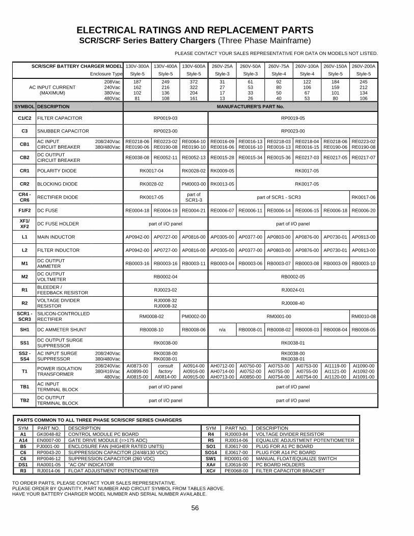
56
ELECTRICAL RATINGS AND REPLACEMENT PARTS SCR/SCRF Series Battery Chargers (Three Phase Mainframe)
PLEASE CONTACT YOUR SALES REPRESENTATIVE FOR DATA ON MODELS NOT LISTED.
SCR/SCRF BATTERY CHARGER MODEL 130V-300A 130V-400A 130V-600A 260V-25A 260V-50A 260V-75A 260V-100A 260V-150A 260V-200A
Enclosure Type Style-5 Style-5 Style-5 Style-3 Style-3 Style-4 Style-4 Style-5 Style-5
AC INPUT CURRENT (MAXIMUM)
208Vac 240Vac 380Vac 480Vac
187 162 102 81
249 216 136 108
372 322 204 161
31 27 17 13
61 53 33 26
92 80 50 40
122 106 67 53
184 159 101 80
245 212 134 106
SYMBOL DESCRIPTION MANUFACTURER'S PART No.
C1/C2 FILTER CAPACITOR RP0019-03 RP0019-05
C3 SNUBBER CAPACITOR RP0023-00 RP0023-00
CB1 AC INPUT CIRCUIT BREAKER
208/240Vac 380/480Vac
RE0218-06 RE0190-06
RE0223-02 RE0190-08
RE0064-10 RE0190-10
RE0016-09 RE0016-06
RE0016-13 RE0016-10
RE0218-03 RE0016-13
RE0218-04 RE0016-15
RE0218-06 RE0190-06
RE0223-02 RE0190-08
CB2 DC OUTPUT CIRCUIT BREAKER RE0038-08 RE0052-11 RE0052-13 RE0015-28 RE0015-34 RE0015-36 RE0217-03 RE0217-05 RE0217-07
CR1 POLARITY DIODE RK0017-04 RK0028-02 RK0009-05 RK0017-05
CR2 BLOCKING DIODE RK0028-02 PM0003-00 RK0013-05 RK0017-05
CR4 - CR6 RECTIFIER DIODE RK0017-05 part of
SCR1-3 part of SCR1 - SCR3 RK0017-06
F1/F2 DC FUSE RE0004-18 RE0004-19 RE0004-21 RE0006-07 RE0006-11 RE0006-14 RE0006-15 RE0006-18 RE0006-20
XF1/ XF2 DC FUSE HOLDER part of I/O panel part of I/O panel
L1 MAIN INDUCTOR AP0942-00 AP0727-00 AP0816-00 AP0305-00 AP0377-00 AP0803-00 AP0876-00 AP0730-01 AP0913-00
L2 FILTER INDUCTOR AP0942-00 AP0727-00 AP0816-00 AP0305-00 AP0377-00 AP0803-00 AP0876-00 AP0730-01 AP0913-00
M1 DC OUTPUT AMMETER RB0003-16 RB0003-16 RB0003-11 RB0003-04 RB0003-06 RB0003-07 RB0003-08 RB0003-09 RB0003-10
M2 DC OUTPUT VOLTMETER RB0002-04 RB0002-05
R1 BLEEDER / FEEDBACK RESISTOR RJ0023-02 RJ0024-01
R2 VOLTAGE DIVIDER RESISTOR
RJ0008-32 RJ0008-32 RJ0008-40
SCR1 - SCR3
SILICON-CONTROLLED RECTIFIER RM0008-02 PM0002-00 RM0001-00 RM0010-08
SH1 DC AMMETER SHUNT RB0008-10 RB0008-06 n/a RB0008-01 RB0008-02 RB0008-03 RB0008-04 RB0008-05
SS1 DC OUTPUT SURGE SUPPRESSOR RK0038-00 RK0038-01
SS2 - SS4
AC INPUT SURGE SUPPRESSOR
208/240Vac 380/480Vac
RK0038-00 RK0038-01
RK0038-00 RK0038-01
T1 POWER ISOLATION TRANSFORMER
208/240Vac 380/416Vac
480Vac
AI0873-00 AI0899-00 AI0815-00
consult factory
AI0814-00
AI0914-00 AI0916-00 AI0915-00
AH0712-00 AH0714-00 AH0713-00
AI0750-00 AI0752-00 AI0850-00
AI0753-00 AI0755-00 AI0754-00
AI0753-00 AI0755-00 AI0754-00
AI1119-00 AI1121-00 AI1120-00
AI1090-00 AI1092-00 AI1091-00
TB1 AC INPUT TERMINAL BLOCK part of I/O panel part of I/O panel
TB2 DC OUTPUT TERMINAL BLOCK part of I/O panel part of I/O panel
PARTS COMMON TO ALL THREE PHASE SCR/SCRF SERIES CHARGERS
SYM PART NO. DESCRIPTION SYM PART NO. DESCRIPTION A1 GK0048-82 CONTROL MODULE PC BOARD R4 RJ0003-84 VOLTAGE DIVIDER RESISTOR A14 EN0007-00 GATE DRIVE MODULE (=>175 ADC) R5 RJ0014-06 EQUALIZE ADJUSTMENT POTENTIOMETER B5 PJ0001-00 ENCLOSURE FAN (HIGHER RATED UNITS) SO1 EJ0617-00 PLUG FOR A1 PC BOARD C6 RP0043-20 SUPPRESSION CAPACITOR (24/48/130 VDC) SO14 EJ0617-00 PLUG FOR A14 PC BOARD C6 RP0046-12 SUPPRESSION CAPACITOR (260 VDC) SW1 RD0001-00 MANUAL FLOAT/EQUALIZE SWITCH
DS1 RA0001-05 "AC ON" INDICATOR XA# EJ0616-00 PC BOARD HOLDERS R3 RJ0014-06 FLOAT ADJUSTMENT POTENTIOMETER XC# PE0068-00 FILTER CAPACITOR BRACKET
TO ORDER PARTS, PLEASE CONTACT YOUR SALES REPRESENTATIVE. PLEASE ORDER BY QUANTITY, PART NUMBER AND CIRCUIT SYMBOL FROM TABLES ABOVE. HAVE YOUR BATTERY CHARGER MODEL NUMBER AND SERIAL NUMBER AVAILABLE.
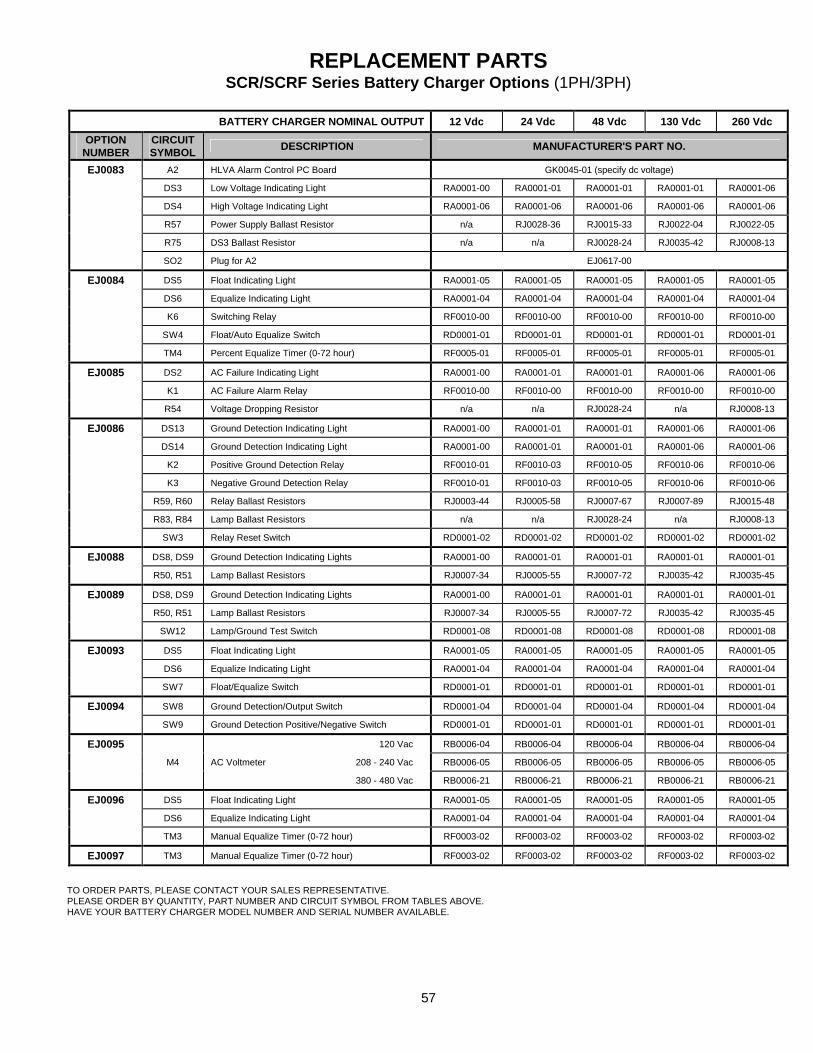
57
REPLACEMENT PARTS SCR/SCRF Series Battery Charger Options (1PH/3PH)
BATTERY CHARGER NOMINAL OUTPUT 12 Vdc 24 Vdc 48 Vdc 130 Vdc 260 Vdc
OPTION NUMBER
CIRCUIT SYMBOL DESCRIPTION MANUFACTURER'S PART NO.
EJ0083 A2 HLVA Alarm Control PC Board GK0045-01 (specify dc voltage)
DS3 Low Voltage Indicating Light RA0001-00 RA0001-01 RA0001-01 RA0001-01 RA0001-06
DS4 High Voltage Indicating Light RA0001-06 RA0001-06 RA0001-06 RA0001-06 RA0001-06
R57 Power Supply Ballast Resistor n/a RJ0028-36 RJ0015-33 RJ0022-04 RJ0022-05
R75 DS3 Ballast Resistor n/a n/a RJ0028-24 RJ0035-42 RJ0008-13
SO2 Plug for A2 EJ0617-00
EJ0084 DS5 Float Indicating Light RA0001-05 RA0001-05 RA0001-05 RA0001-05 RA0001-05
DS6 Equalize Indicating Light RA0001-04 RA0001-04 RA0001-04 RA0001-04 RA0001-04
K6 Switching Relay RF0010-00 RF0010-00 RF0010-00 RF0010-00 RF0010-00
SW4 Float/Auto Equalize Switch RD0001-01 RD0001-01 RD0001-01 RD0001-01 RD0001-01
TM4 Percent Equalize Timer (0-72 hour) RF0005-01 RF0005-01 RF0005-01 RF0005-01 RF0005-01
EJ0085 DS2 AC Failure Indicating Light RA0001-00 RA0001-01 RA0001-01 RA0001-06 RA0001-06
K1 AC Failure Alarm Relay RF0010-00 RF0010-00 RF0010-00 RF0010-00 RF0010-00
R54 Voltage Dropping Resistor n/a n/a RJ0028-24 n/a RJ0008-13
EJ0086 DS13 Ground Detection Indicating Light RA0001-00 RA0001-01 RA0001-01 RA0001-06 RA0001-06
DS14 Ground Detection Indicating Light RA0001-00 RA0001-01 RA0001-01 RA0001-06 RA0001-06
K2 Positive Ground Detection Relay RF0010-01 RF0010-03 RF0010-05 RF0010-06 RF0010-06
K3 Negative Ground Detection Relay RF0010-01 RF0010-03 RF0010-05 RF0010-06 RF0010-06
R59, R60 Relay Ballast Resistors RJ0003-44 RJ0005-58 RJ0007-67 RJ0007-89 RJ0015-48
R83, R84 Lamp Ballast Resistors n/a n/a RJ0028-24 n/a RJ0008-13
SW3 Relay Reset Switch RD0001-02 RD0001-02 RD0001-02 RD0001-02 RD0001-02
EJ0088 DS8, DS9 Ground Detection Indicating Lights RA0001-00 RA0001-01 RA0001-01 RA0001-01 RA0001-01
R50, R51 Lamp Ballast Resistors RJ0007-34 RJ0005-55 RJ0007-72 RJ0035-42 RJ0035-45
EJ0089 DS8, DS9 Ground Detection Indicating Lights RA0001-00 RA0001-01 RA0001-01 RA0001-01 RA0001-01
R50, R51 Lamp Ballast Resistors RJ0007-34 RJ0005-55 RJ0007-72 RJ0035-42 RJ0035-45
SW12 Lamp/Ground Test Switch RD0001-08 RD0001-08 RD0001-08 RD0001-08 RD0001-08
EJ0093 DS5 Float Indicating Light RA0001-05 RA0001-05 RA0001-05 RA0001-05 RA0001-05
DS6 Equalize Indicating Light RA0001-04 RA0001-04 RA0001-04 RA0001-04 RA0001-04
SW7 Float/Equalize Switch RD0001-01 RD0001-01 RD0001-01 RD0001-01 RD0001-01
EJ0094 SW8 Ground Detection/Output Switch RD0001-04 RD0001-04 RD0001-04 RD0001-04 RD0001-04
SW9 Ground Detection Positive/Negative Switch RD0001-01 RD0001-01 RD0001-01 RD0001-01 RD0001-01
EJ0095 120 Vac RB0006-04 RB0006-04 RB0006-04 RB0006-04 RB0006-04
M4 AC Voltmeter 208 - 240 Vac RB0006-05 RB0006-05 RB0006-05 RB0006-05 RB0006-05
380 - 480 Vac RB0006-21 RB0006-21 RB0006-21 RB0006-21 RB0006-21
EJ0096 DS5 Float Indicating Light RA0001-05 RA0001-05 RA0001-05 RA0001-05 RA0001-05
DS6 Equalize Indicating Light RA0001-04 RA0001-04 RA0001-04 RA0001-04 RA0001-04
TM3 Manual Equalize Timer (0-72 hour) RF0003-02 RF0003-02 RF0003-02 RF0003-02 RF0003-02
EJ0097 TM3 Manual Equalize Timer (0-72 hour) RF0003-02 RF0003-02 RF0003-02 RF0003-02 RF0003-02
TO ORDER PARTS, PLEASE CONTACT YOUR SALES REPRESENTATIVE. PLEASE ORDER BY QUANTITY, PART NUMBER AND CIRCUIT SYMBOL FROM TABLES ABOVE. HAVE YOUR BATTERY CHARGER MODEL NUMBER AND SERIAL NUMBER AVAILABLE.
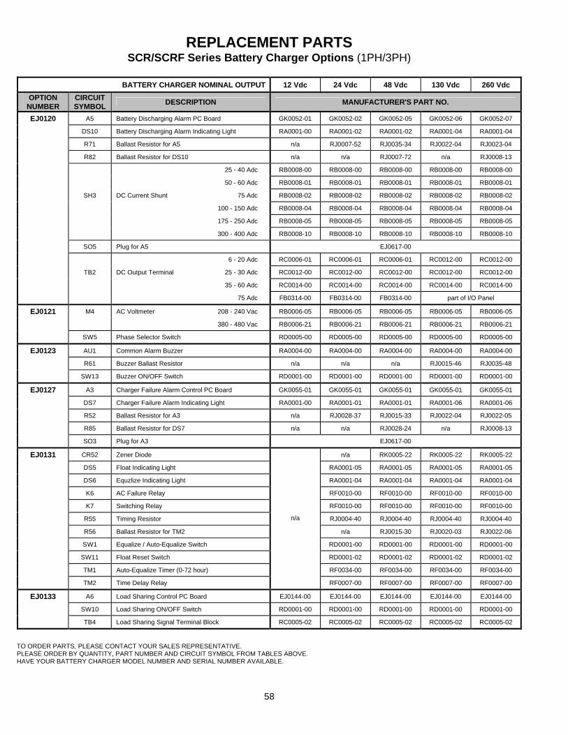
58
REPLACEMENT PARTS SCR/SCRF Series Battery Charger Options (1PH/3PH)
BATTERY CHARGER NOMINAL OUTPUT 12 Vdc 24 Vdc 48 Vdc 130 Vdc 260 Vdc
OPTION NUMBER
CIRCUIT SYMBOL DESCRIPTION MANUFACTURER'S PART NO.
EJ0120 A5 Battery Discharging Alarm PC Board GK0052-01 GK0052-02 GK0052-05 GK0052-06 GK0052-07
DS10 Battery Discharging Alarm Indicating Light RA0001-00 RA0001-02 RA0001-02 RA0001-04 RA0001-04
R71 Ballast Resistor for A5 n/a RJ0007-52 RJ0035-34 RJ0022-04 RJ0023-04
R82 Ballast Resistor for DS10 n/a n/a RJ0007-72 n/a RJ0008-13
25 - 40 Adc RB0008-00 RB0008-00 RB0008-00 RB0008-00 RB0008-00
50 - 60 Adc RB0008-01 RB0008-01 RB0008-01 RB0008-01 RB0008-01
SH3 DC Current Shunt 75 Adc RB0008-02 RB0008-02 RB0008-02 RB0008-02 RB0008-02
100 - 150 Adc RB0008-04 RB0008-04 RB0008-04 RB0008-04 RB0008-04
175 - 250 Adc RB0008-05 RB0008-05 RB0008-05 RB0008-05 RB0008-05
300 - 400 Adc RB0008-10 RB0008-10 RB0008-10 RB0008-10 RB0008-10
SO5 Plug for A5 EJ0617-00
6 - 20 Adc RC0006-01 RC0006-01 RC0006-01 RC0012-00 RC0012-00
TB2 DC Output Terminal 25 - 30 Adc RC0012-00 RC0012-00 RC0012-00 RC0012-00 RC0012-00
35 - 60 Adc RC0014-00 RC0014-00 RC0014-00 RC0014-00 RC0014-00
75 Adc FB0314-00 FB0314-00 FB0314-00 part of I/O Panel
EJ0121 M4 AC Voltmeter 208 - 240 Vac RB0006-05 RB0006-05 RB0006-05 RB0006-05 RB0006-05
380 - 480 Vac RB0006-21 RB0006-21 RB0006-21 RB0006-21 RB0006-21
SW5 Phase Selector Switch RD0005-00 RD0005-00 RD0005-00 RD0005-00 RD0005-00
EJ0123 AU1 Common Alarm Buzzer RA0004-00 RA0004-00 RA0004-00 RA0004-00 RA0004-00
R61 Buzzer Ballast Resistor n/a n/a n/a RJ0015-46 RJ0035-48
SW13 Buzzer ON/OFF Switch RD0001-00 RD0001-00 RD0001-00 RD0001-00 RD0001-00
EJ0127 A3 Charger Failure Alarm Control PC Board GK0055-01 GK0055-01 GK0055-01 GK0055-01 GK0055-01
DS7 Charger Failure Alarm Indicating Light RA0001-00 RA0001-01 RA0001-01 RA0001-06 RA0001-06
R52 Ballast Resistor for A3 n/a RJ0028-37 RJ0015-33 RJ0022-04 RJ0022-05
R85 Ballast Resistor for DS7 n/a n/a RJ0028-24 n/a RJ0008-13
SO3 Plug for A3 EJ0617-00
EJ0131 CR52 Zener Diode n/a RK0005-22 RK0005-22 RK0005-22
DS5 Float Indicating Light RA0001-05 RA0001-05 RA0001-05 RA0001-05
DS6 Equzlize Indicating Light RA0001-04 RA0001-04 RA0001-04 RA0001-04
K6 AC Failure Relay RF0010-00 RF0010-00 RF0010-00 RF0010-00
K7 Switching Relay RF0010-00 RF0010-00 RF0010-00 RF0010-00
R55 Timing Resistor RJ0004-40 RJ0004-40 RJ0004-40 RJ0004-40
R56 Ballast Resistor for TM2 n/a RJ0015-30 RJ0020-03 RJ0022-06
SW1 Equalize / Auto-Equalize Switch RD0001-00 RD0001-00 RD0001-00 RD0001-00
SW11 Float Reset Switch RD0001-02 RD0001-02 RD0001-02 RD0001-02
TM1 Auto-Equalize Timer (0-72 hour) RF0034-00 RF0034-00 RF0034-00 RF0034-00
TM2 Time Delay Relay
n/a
RF0007-00 RF0007-00 RF0007-00 RF0007-00
EJ0133 A6 Load Sharing Control PC Board EJ0144-00 EJ0144-00 EJ0144-00 EJ0144-00 EJ0144-00
SW10 Load Sharing ON/OFF Switch RD0001-00 RD0001-00 RD0001-00 RD0001-00 RD0001-00
TB4 Load Sharing Signal Terminal Block RC0005-02 RC0005-02 RC0005-02 RC0005-02 RC0005-02
TO ORDER PARTS, PLEASE CONTACT YOUR SALES REPRESENTATIVE. PLEASE ORDER BY QUANTITY, PART NUMBER AND CIRCUIT SYMBOL FROM TABLES ABOVE. HAVE YOUR BATTERY CHARGER MODEL NUMBER AND SERIAL NUMBER AVAILABLE.
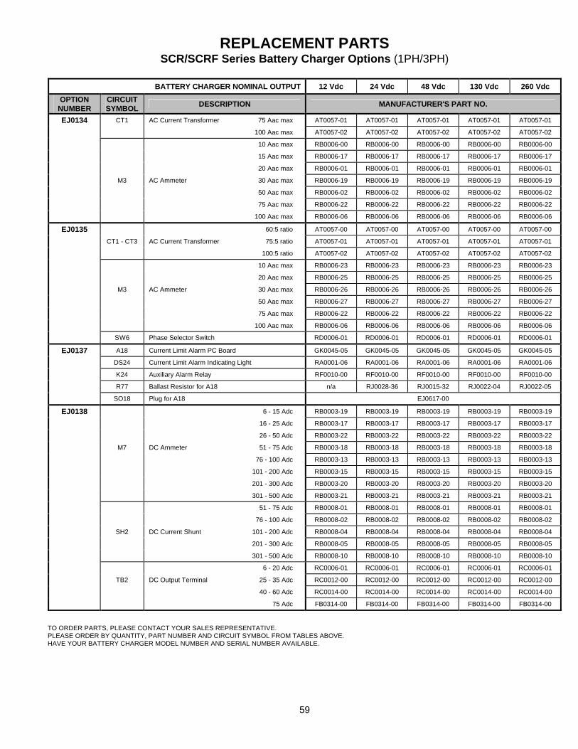
59
REPLACEMENT PARTS SCR/SCRF Series Battery Charger Options (1PH/3PH)
BATTERY CHARGER NOMINAL OUTPUT 12 Vdc 24 Vdc 48 Vdc 130 Vdc 260 Vdc
OPTION NUMBER
CIRCUIT SYMBOL DESCRIPTION MANUFACTURER'S PART NO.
EJ0134 CT1 AC Current Transformer 75 Aac max AT0057-01 AT0057-01 AT0057-01 AT0057-01 AT0057-01
100 Aac max AT0057-02 AT0057-02 AT0057-02 AT0057-02 AT0057-02
10 Aac max RB0006-00 RB0006-00 RB0006-00 RB0006-00 RB0006-00
15 Aac max RB0006-17 RB0006-17 RB0006-17 RB0006-17 RB0006-17
20 Aac max RB0006-01 RB0006-01 RB0006-01 RB0006-01 RB0006-01
M3 AC Ammeter 30 Aac max RB0006-19 RB0006-19 RB0006-19 RB0006-19 RB0006-19
50 Aac max RB0006-02 RB0006-02 RB0006-02 RB0006-02 RB0006-02
75 Aac max RB0006-22 RB0006-22 RB0006-22 RB0006-22 RB0006-22
100 Aac max RB0006-06 RB0006-06 RB0006-06 RB0006-06 RB0006-06
EJ0135 60:5 ratio AT0057-00 AT0057-00 AT0057-00 AT0057-00 AT0057-00
CT1 - CT3 AC Current Transformer 75:5 ratio AT0057-01 AT0057-01 AT0057-01 AT0057-01 AT0057-01
100:5 ratio AT0057-02 AT0057-02 AT0057-02 AT0057-02 AT0057-02
10 Aac max RB0006-23 RB0006-23 RB0006-23 RB0006-23 RB0006-23
20 Aac max RB0006-25 RB0006-25 RB0006-25 RB0006-25 RB0006-25
M3 AC Ammeter 30 Aac max RB0006-26 RB0006-26 RB0006-26 RB0006-26 RB0006-26
50 Aac max RB0006-27 RB0006-27 RB0006-27 RB0006-27 RB0006-27
75 Aac max RB0006-22 RB0006-22 RB0006-22 RB0006-22 RB0006-22
100 Aac max RB0006-06 RB0006-06 RB0006-06 RB0006-06 RB0006-06
SW6 Phase Selector Switch RD0006-01 RD0006-01 RD0006-01 RD0006-01 RD0006-01
EJ0137 A18 Current Limit Alarm PC Board GK0045-05 GK0045-05 GK0045-05 GK0045-05 GK0045-05
DS24 Current Limit Alarm Indicating Light RA0001-06 RA0001-06 RA0001-06 RA0001-06 RA0001-06
K24 Auxiliary Alarm Relay RF0010-00 RF0010-00 RF0010-00 RF0010-00 RF0010-00
R77 Ballast Resistor for A18 n/a RJ0028-36 RJ0015-32 RJ0022-04 RJ0022-05
SO18 Plug for A18 EJ0617-00
EJ0138 6 - 15 Adc RB0003-19 RB0003-19 RB0003-19 RB0003-19 RB0003-19
16 - 25 Adc RB0003-17 RB0003-17 RB0003-17 RB0003-17 RB0003-17
26 - 50 Adc RB0003-22 RB0003-22 RB0003-22 RB0003-22 RB0003-22
M7 DC Ammeter 51 - 75 Adc RB0003-18 RB0003-18 RB0003-18 RB0003-18 RB0003-18
76 - 100 Adc RB0003-13 RB0003-13 RB0003-13 RB0003-13 RB0003-13
101 - 200 Adc RB0003-15 RB0003-15 RB0003-15 RB0003-15 RB0003-15
201 - 300 Adc RB0003-20 RB0003-20 RB0003-20 RB0003-20 RB0003-20
301 - 500 Adc RB0003-21 RB0003-21 RB0003-21 RB0003-21 RB0003-21
51 - 75 Adc RB0008-01 RB0008-01 RB0008-01 RB0008-01 RB0008-01
76 - 100 Adc RB0008-02 RB0008-02 RB0008-02 RB0008-02 RB0008-02
SH2 DC Current Shunt 101 - 200 Adc RB0008-04 RB0008-04 RB0008-04 RB0008-04 RB0008-04
201 - 300 Adc RB0008-05 RB0008-05 RB0008-05 RB0008-05 RB0008-05
301 - 500 Adc RB0008-10 RB0008-10 RB0008-10 RB0008-10 RB0008-10
6 - 20 Adc RC0006-01 RC0006-01 RC0006-01 RC0006-01 RC0006-01
TB2 DC Output Terminal 25 - 35 Adc RC0012-00 RC0012-00 RC0012-00 RC0012-00 RC0012-00
40 - 60 Adc RC0014-00 RC0014-00 RC0014-00 RC0014-00 RC0014-00
75 Adc FB0314-00 FB0314-00 FB0314-00 FB0314-00 FB0314-00
TO ORDER PARTS, PLEASE CONTACT YOUR SALES REPRESENTATIVE. PLEASE ORDER BY QUANTITY, PART NUMBER AND CIRCUIT SYMBOL FROM TABLES ABOVE. HAVE YOUR BATTERY CHARGER MODEL NUMBER AND SERIAL NUMBER AVAILABLE.
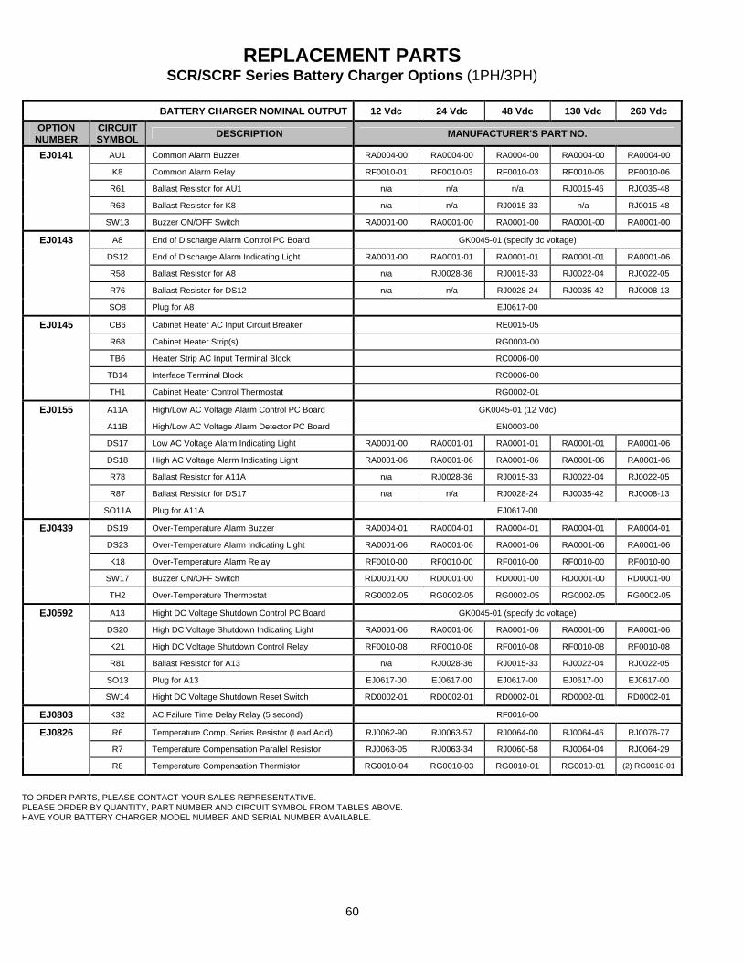
60
REPLACEMENT PARTS SCR/SCRF Series Battery Charger Options (1PH/3PH)
BATTERY CHARGER NOMINAL OUTPUT 12 Vdc 24 Vdc 48 Vdc 130 Vdc 260 Vdc
OPTION NUMBER
CIRCUIT SYMBOL DESCRIPTION MANUFACTURER'S PART NO.
EJ0141 AU1 Common Alarm Buzzer RA0004-00 RA0004-00 RA0004-00 RA0004-00 RA0004-00
K8 Common Alarm Relay RF0010-01 RF0010-03 RF0010-03 RF0010-06 RF0010-06
R61 Ballast Resistor for AU1 n/a n/a n/a RJ0015-46 RJ0035-48
R63 Ballast Resistor for K8 n/a n/a RJ0015-33 n/a RJ0015-48
SW13 Buzzer ON/OFF Switch RA0001-00 RA0001-00 RA0001-00 RA0001-00 RA0001-00
EJ0143 A8 End of Discharge Alarm Control PC Board GK0045-01 (specify dc voltage)
DS12 End of Discharge Alarm Indicating Light RA0001-00 RA0001-01 RA0001-01 RA0001-01 RA0001-06
R58 Ballast Resistor for A8 n/a RJ0028-36 RJ0015-33 RJ0022-04 RJ0022-05
R76 Ballast Resistor for DS12 n/a n/a RJ0028-24 RJ0035-42 RJ0008-13
SO8 Plug for A8 EJ0617-00
EJ0145 CB6 Cabinet Heater AC Input Circuit Breaker RE0015-05
R68 Cabinet Heater Strip(s) RG0003-00
TB6 Heater Strip AC Input Terminal Block RC0006-00
TB14 Interface Terminal Block RC0006-00
TH1 Cabinet Heater Control Thermostat RG0002-01
EJ0155 A11A High/Low AC Voltage Alarm Control PC Board GK0045-01 (12 Vdc)
A11B High/Low AC Voltage Alarm Detector PC Board EN0003-00
DS17 Low AC Voltage Alarm Indicating Light RA0001-00 RA0001-01 RA0001-01 RA0001-01 RA0001-06
DS18 High AC Voltage Alarm Indicating Light RA0001-06 RA0001-06 RA0001-06 RA0001-06 RA0001-06
R78 Ballast Resistor for A11A n/a RJ0028-36 RJ0015-33 RJ0022-04 RJ0022-05
R87 Ballast Resistor for DS17 n/a n/a RJ0028-24 RJ0035-42 RJ0008-13
SO11A Plug for A11A EJ0617-00
EJ0439 DS19 Over-Temperature Alarm Buzzer RA0004-01 RA0004-01 RA0004-01 RA0004-01 RA0004-01
DS23 Over-Temperature Alarm Indicating Light RA0001-06 RA0001-06 RA0001-06 RA0001-06 RA0001-06
K18 Over-Temperature Alarm Relay RF0010-00 RF0010-00 RF0010-00 RF0010-00 RF0010-00
SW17 Buzzer ON/OFF Switch RD0001-00 RD0001-00 RD0001-00 RD0001-00 RD0001-00
TH2 Over-Temperature Thermostat RG0002-05 RG0002-05 RG0002-05 RG0002-05 RG0002-05
EJ0592 A13 Hight DC Voltage Shutdown Control PC Board GK0045-01 (specify dc voltage)
DS20 High DC Voltage Shutdown Indicating Light RA0001-06 RA0001-06 RA0001-06 RA0001-06 RA0001-06
K21 High DC Voltage Shutdown Control Relay RF0010-08 RF0010-08 RF0010-08 RF0010-08 RF0010-08
R81 Ballast Resistor for A13 n/a RJ0028-36 RJ0015-33 RJ0022-04 RJ0022-05
SO13 Plug for A13 EJ0617-00 EJ0617-00 EJ0617-00 EJ0617-00 EJ0617-00
SW14 Hight DC Voltage Shutdown Reset Switch RD0002-01 RD0002-01 RD0002-01 RD0002-01 RD0002-01
EJ0803 K32 AC Failure Time Delay Relay (5 second) RF0016-00
EJ0826 R6 Temperature Comp. Series Resistor (Lead Acid) RJ0062-90 RJ0063-57 RJ0064-00 RJ0064-46 RJ0076-77
R7 Temperature Compensation Parallel Resistor RJ0063-05 RJ0063-34 RJ0060-58 RJ0064-04 RJ0064-29
R8 Temperature Compensation Thermistor RG0010-04 RG0010-03 RG0010-01 RG0010-01 (2) RG0010-01
TO ORDER PARTS, PLEASE CONTACT YOUR SALES REPRESENTATIVE. PLEASE ORDER BY QUANTITY, PART NUMBER AND CIRCUIT SYMBOL FROM TABLES ABOVE. HAVE YOUR BATTERY CHARGER MODEL NUMBER AND SERIAL NUMBER AVAILABLE.
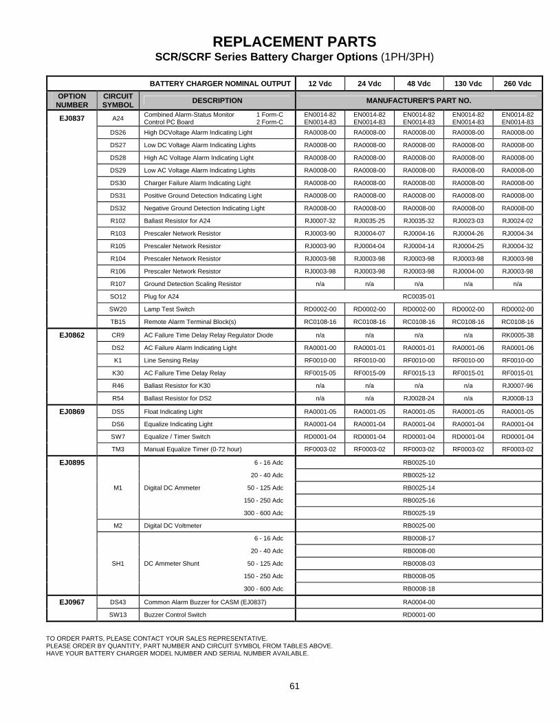
61
REPLACEMENT PARTS SCR/SCRF Series Battery Charger Options (1PH/3PH)
BATTERY CHARGER NOMINAL OUTPUT 12 Vdc 24 Vdc 48 Vdc 130 Vdc 260 Vdc
OPTION NUMBER
CIRCUIT SYMBOL DESCRIPTION MANUFACTURER'S PART NO.
EJ0837 A24 Combined Alarm-Status Monitor 1 Form-C Control PC Board 2 Form-C
EN0014-82 EN0014-83
EN0014-82 EN0014-83
EN0014-82 EN0014-83
EN0014-82 EN0014-83
EN0014-82 EN0014-83
DS26 High DCVoltage Alarm Indicating Light RA0008-00 RA0008-00 RA0008-00 RA0008-00 RA0008-00
DS27 Low DC Voltage Alarm Indicating Lights RA0008-00 RA0008-00 RA0008-00 RA0008-00 RA0008-00
DS28 High AC Voltage Alarm Indicating Light RA0008-00 RA0008-00 RA0008-00 RA0008-00 RA0008-00
DS29 Low AC Voltage Alarm Indicating Lights RA0008-00 RA0008-00 RA0008-00 RA0008-00 RA0008-00
DS30 Charger Failure Alarm Indicating Light RA0008-00 RA0008-00 RA0008-00 RA0008-00 RA0008-00
DS31 Positive Ground Detection Indicating Light RA0008-00 RA0008-00 RA0008-00 RA0008-00 RA0008-00
DS32 Negative Ground Detection Indicating Light RA0008-00 RA0008-00 RA0008-00 RA0008-00 RA0008-00
R102 Ballast Resistor for A24 RJ0007-32 RJ0035-25 RJ0035-32 RJ0023-03 RJ0024-02
R103 Prescaler Network Resistor RJ0003-90 RJ0004-07 RJ0004-16 RJ0004-26 RJ0004-34
R105 Prescaler Network Resistor RJ0003-90 RJ0004-04 RJ0004-14 RJ0004-25 RJ0004-32
R104 Prescaler Network Resistor RJ0003-98 RJ0003-98 RJ0003-98 RJ0003-98 RJ0003-98
R106 Prescaler Network Resistor RJ0003-98 RJ0003-98 RJ0003-98 RJ0004-00 RJ0003-98
R107 Ground Detection Scaling Resistor n/a n/a n/a n/a n/a
SO12 Plug for A24 RC0035-01
SW20 Lamp Test Switch RD0002-00 RD0002-00 RD0002-00 RD0002-00 RD0002-00
TB15 Remote Alarm Terminal Block(s) RC0108-16 RC0108-16 RC0108-16 RC0108-16 RC0108-16
EJ0862 CR9 AC Failure Time Delay Relay Regulator Diode n/a n/a n/a n/a RK0005-38
DS2 AC Failure Alarm Indicating Light RA0001-00 RA0001-01 RA0001-01 RA0001-06 RA0001-06
K1 Line Sensing Relay RF0010-00 RF0010-00 RF0010-00 RF0010-00 RF0010-00
K30 AC Failure Time Delay Relay RF0015-05 RF0015-09 RF0015-13 RF0015-01 RF0015-01
R46 Ballast Resistor for K30 n/a n/a n/a n/a RJ0007-96
R54 Ballast Resistor for DS2 n/a n/a RJ0028-24 n/a RJ0008-13
EJ0869 DS5 Float Indicating Light RA0001-05 RA0001-05 RA0001-05 RA0001-05 RA0001-05
DS6 Equalize Indicating Light RA0001-04 RA0001-04 RA0001-04 RA0001-04 RA0001-04
SW7 Equalize / Timer Switch RD0001-04 RD0001-04 RD0001-04 RD0001-04 RD0001-04
TM3 Manual Equalize Timer (0-72 hour) RF0003-02 RF0003-02 RF0003-02 RF0003-02 RF0003-02
EJ0895 6 - 16 Adc RB0025-10
20 - 40 Adc RB0025-12
M1 Digital DC Ammeter 50 - 125 Adc RB0025-14
150 - 250 Adc RB0025-16
300 - 600 Adc RB0025-19
M2 Digital DC Voltmeter RB0025-00
6 - 16 Adc RB0008-17
20 - 40 Adc RB0008-00
SH1 DC Ammeter Shunt 50 - 125 Adc RB0008-03
150 - 250 Adc RB0008-05
300 - 600 Adc RB0008-18
EJ0967 DS43 Common Alarm Buzzer for CASM (EJ0837) RA0004-00
SW13 Buzzer Control Switch RD0001-00
TO ORDER PARTS, PLEASE CONTACT YOUR SALES REPRESENTATIVE. PLEASE ORDER BY QUANTITY, PART NUMBER AND CIRCUIT SYMBOL FROM TABLES ABOVE. HAVE YOUR BATTERY CHARGER MODEL NUMBER AND SERIAL NUMBER AVAILABLE.
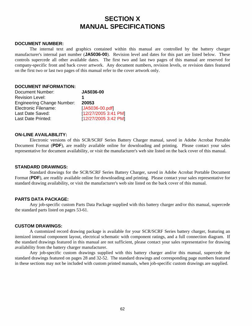
62
SECTION X MANUAL SPECIFICATIONS
DOCUMENT NUMBER: The internal text and graphics contained within this manual are controlled by the battery charger manufacturer's internal part number (JA5036-00). Revision level and dates for this part are listed below. These controls supercede all other available dates. The first two and last two pages of this manual are reserved for company-specific front and back cover artwork. Any document numbers, revision levels, or revision dates featured on the first two or last two pages of this manual refer to the cover artwork only. DOCUMENT INFORMATION: Document Number: JA5036-00 Revision Level: 1 Engineering Change Number: 20053 Electronic Filename: [JA5036-00.pdf] Last Date Saved: [12/27/2005 3:41 PM] Last Date Printed: [12/27/2005 3:42 PM] ON-LINE AVAILABILITY: Electronic versions of this SCR/SCRF Series Battery Charger manual, saved in Adobe Acrobat Portable Document Format (PDF), are readily available online for downloading and printing. Please contact your sales representative for document availability, or visit the manufacturer's web site listed on the back cover of this manual. STANDARD DRAWINGS: Standard drawings for the SCR/SCRF Series Battery Charger, saved in Adobe Acrobat Portable Document Format (PDF), are readily available online for downloading and printing. Please contact your sales representative for standard drawing availability, or visit the manufacturer's web site listed on the back cover of this manual. PARTS DATA PACKAGE: Any job-specific custom Parts Data Package supplied with this battery charger and/or this manual, supercede the standard parts listed on pages 53-61. CUSTOM DRAWINGS: A customized record drawing package is available for your SCR/SCRF Series battery charger, featuring an itemized internal component layout, electrical schematic with component ratings, and a full connection diagram. If the standard drawings featured in this manual are not sufficient, please contact your sales representative for drawing availability from the battery charger manufacturer. Any job-specific custom drawings supplied with this battery charger and/or this manual, supercede the standard drawings featured on pages 28 and 32-52. The standard drawings and corresponding page numbers featured in these sections may not be included with custom printed manuals, when job-specific custom drawings are supplied.
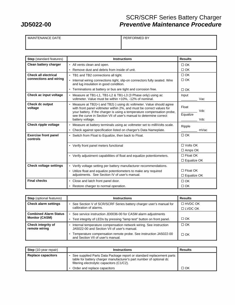
SCR/SCRF Series Battery Charger JD5022-00 Preventive Maintenance Procedure
MAINTENANCE DATE
PERFORMED BY
Step (standard features) Instructions Results
Clean battery charger • All vents clean and open.
• Remove dust and debris from inside of unit. ¨ OK ¨ OK
Check all electrical connections and wiring
• TB1 and TB2 connections all tight.
• Internal wiring connections tight, slip-on connectors fully seated. Wire and lug insulation in good condition.
• Terminations at battery or bus are tight and corrosion free.
¨ OK ¨ OK ¨ OK
Check ac input voltage • Measure at TB1-L1, TB1-L2 & TB1-L3 (3 Phase only) using ac voltmeter. Value must be within +10%, -12% of nominal.
Input Vac
Check dc output voltage
• Measure at TB2(+) and TB2(-) using dc voltmeter. Value should agree with front panel voltmeter within 2%, and must be correct values for your battery. If the charger is using a temperature compensation probe, see the curve in Section VII of user's manual to determine correct battery voltage.
Float Vdc Equalize Vdc
Check ripple voltage • Measure at battery terminals using ac voltmeter set to milliVolts scale.
• Check against specification listed on charger's Data Nameplate. Ripple mVac
Exercise front panel controls
• Switch from Float to Equalize, then back to Float. ¨ OK
• Verify front panel meters functional ¨ Volts OK ¨ Amps OK
• Verify adjustment capabilities of float and equalize potentiometers. ¨ Float OK ¨ Equalize OK
Check voltage settings • Verify voltage setting per battery manufacturer recommendations.
• Utilize float and equalize potentiometers to make any required adjustments. See Section IV of user's manual.
¨ Float OK ¨ Equalize OK
Final checks • Close and latch front panel door.
• Restore charger to normal operation. ¨ OK ¨ OK
Step (optional features) Instructions Results
Check alarm settings • See Section V of SCR/SCRF Series battery charger user’s manual for calibration of alarms.
¨ HVDC OK ¨ LVDC OK
Combined Alarm Status Monitor (CASM)
• See service instruction JD0036-00 for CASM alarm adjustments
• Test integrity of LEDs by pressing "lamp test" button on front panel.
¨ OK
Check integrity of remote wiring
• Internal temperature compensation network wiring. See instruction JA5022-00 and Section VII of user's manual.
• Temperature compensation remote probe. See instruction JA5022-00 and Section VII of user's manual.
¨ OK ¨ OK
Step (10-year repair) Instructions Results
Replace capacitors • See supplied Parts Data Package report or standard replacement parts table for battery charger manufacturer's part number of optional dc filtering electrolytic capacitors (C1/C2).
• Order and replace capacitors ¨ OK
BASIC START-UP AND SHUT DOWN INSTRUCTIONS
START UP Switch "ON" DC Circuit Breaker. Switch "ON" AC Circuit Breaker. SHUT DOWN Switch "OFF" AC Circuit Breaker. DC Circuit Breaker may be left "ON" or "OFF". NOTE If Circuit Breakers are not installed, use external devices to remove power to and from the battery charger. WARNING AC and DC Circuit Breakers do not remove power to some components within the battery charger enclosure. Wait one minute after all external power is removed before accessing internal components.
3 Powdered Metals Drive North Haven, CT 06473-3209 Tel.: (203) 985-2500 Fax: (203) 985-2539 www.alcadusa.com JA0047-00 - Rev. 11-2008 ©2008 Alcad Standby Batteries