school electronic security systemsschool electronic security systems school security program version...
TRANSCRIPT

School Electronic Security Systems School Security Program Version 2009.1 Dated: 07 May 2009 Guidelines Prepared By: School Security Program Asset Maintenance Unit Facilities Services Branch
All enquiries associated with this Specification are to be directed to The INSPECTING OFFICER as detailed on the Engineering Schedule
Document Control
VERSION DESCRIPTION / DETAILS OF AMENDMENT DATE
2003/1 Preliminary Draft Mar 2003
2004/1 Consultation Draft Jun 2004
2004/2 Initial Release Aug 2004
2007/1 Update Jul 2007
2008/1 Draft Following Changes to Part 4 May 2008
2009/1 Approved Following Changes to Part 4 Jun 2009

This specification is divided into sections as follows
PART 1 PRELIMINARY CLAUSES
Appendix 1A Technical Data Schedule
Appendix 1B Pricing Schedule
PART 2 CONDITIONS OF OFFER AND CONTRACT
PART 3 DOCUMENTATION, SAMPLES AND TRAINING
Appendix 3A SEC Forms
Appendix 3B Training Certification Form
PART 4 ELECTRONIC SECURITY TECHNICAL SPECIFICATION
Appendix 4A List of Approved Detectors
Appendix 4B Clause 4.15 Compliance Examples
Appendix 4C Fire Hose Reel Water Flow Switch Detail
ENGINEERING SCHEDULE
DRAWINGS
Specification – School Security Systems Ver. 2009/1 Page: 1.4
Preliminary Clauses
1.1 General _________________________________________________________________1
1.2 Site Details_______________________________________________________________1
1.3 Enquiries ________________________________________________________________1
1.4 Tender Evaluation Criteria ___________________________________________________1
1.5 Document Control _________________________________________________________1
1.6 Authorities and Codes ______________________________________________________1
1.7 Compliance ______________________________________________________________2
1.8 Information to be provided with Tender _________________________________________2 1.8.1 Schedules ________________________________________________________ 2 1.8.2 Contact Details________________________________________________________ 2 1.8.3 Relevant Technical Information ___________________________________________ 2
1.9 Post-Offer Negotiations _____________________________________________________3
1.10 Obvious Work ____________________________________________________________3
1.11 Site Meetings _____________________________________________________________3
1.12 Warranty ________________________________________________________________3
1.13 Setting Out_______________________________________________________________3
1.14 Radio Interference _________________________________________________________3
1.15 Installation Development Stages ______________________________________________3 1.15.1 Stage 1______________________________________________________________ 4 1.15.2 Stage 2______________________________________________________________ 4 1.15.3 Stage 3______________________________________________________________ 5
1.16 Inspections and Commissioning ______________________________________________5 1.16.1 Progress Inspections ___________________________________________________ 5 1.16.2 Commissioning Inspection _______________________________________________ 5
1.17 Breakdown and Maintenance Checks __________________________________________6
1.18 Hours of Work ____________________________________________________________6
1.19 Fire Isolations_____________________________________________________________6
1.20 Barricades _______________________________________________________________6
1.21 Asbestos Related Work _____________________________________________________6
1.22 Supplier's Responsibility ____________________________________________________7
1.23 Painting and Finishing ______________________________________________________7
1.24 Existing Equipment ________________________________________________________7
Specification – School Security Systems Ver. 2009/1 Page: 1.5
APPENDIX 1A APPENDIX 1B

Specification – School Security Systems Ver. 2009/1 Page: 1.6
DOCUMENT CONTROL
VERSION DESCRIPTION / DETAILS OF AMENDMENT DATE 2003/1 Preliminary Draft March 2003 2004/1 Consultation Draft June 2004 2004/2 Initial Release August 2004 2007/1 Updated Clause 1.21 – Asbestos Related Work July 2007 2008/1 Draft – Changed EQ to DET May 2008 2009/1 Approved June 2009

Specification – School Security Systems Ver. 2009/1 Page: 1.1
1.1 General The contract documents shall comprise the relevant contract form(s), this Specification and any and all associated drawings. The Department of Education and Training (DET) is exempt from the payment of sales tax. The lowest tender may not necessarily be accepted. No details of this tender are to be discussed with any other organisation or company except where companies require to use other companies services to deliver the equipment or services required to fulfill the tender requirements.
1.2 Site Details Site details are provided on the Engineering Schedule.
1.3 Enquiries All enquiries regarding this tender or to arrange a site inspection shall be directed to the Inspecting Officer. Details are provided on the Engineering Schedule.
1.4 Tender Evaluation Criteria Tenders will be evaluated against the following criteria:-
• Compliance with Specification; • Compliance with commencement and completion dates; and • Value for money.
1.5 Document Control Because of the security nature of the work, tenderers will undertake not to copy drawings, floor plans or specifications sheets concerning this work supplied to them and will also be required to return these documents as described in the following:
• In the case of an unsuccessful tender the documents must be returned immediately. • In the case of a successful tender the documents must be returned on completion of the
work. It should be noted by tenderers that it is not the intention to provide tenderers, or the successful contractor, with detailed plans of the site and its buildings for any length of time. However, these plans will be available for perusal by arrangement with the Inspecting Officer.
1.6 Authorities and Codes The supplied equipment shall be in accordance with the most recent revisions, including amendments and upgrades of the Australian Standards: AS1670 Code for Automatic Fire Alarm installations;
AS1603.4 Automatic Fire Detection and Alarms System - Control and Indicating Equipment;
AS2201 Intruder Alarm Systems (All Parts); AS3000 SAA Wiring Rules
The specification of the British Standards Institute shall apply where no equivalent Australian Standard exists.
The supplied equipment shall also be in accordance with all statutory requirements of:
• The workplace Health and Safety Act 1989; • The Building Code of Australia; • The Fire Safety Act; • The Queensland Fire and Rescue Authority (QFRA); • The Insurance Council of Australia (F.P.I.S);

Specification – School Security Systems Ver. 2009/1 Page: 1.2
• Energex; • Telstra; and • The Australian Communications Authority (ACA).
Where notice is required by, or approval is required from, any statutory authority having jurisdiction, the supplier shall be responsible for giving such notice or making application for such approval. The supplier shall obtain all permits/approvals within the specified statutory time frames so as to cause no delay to the work, and shall pay all associated fees. Equipment and systems which do not conform to these minimum requirements will rejected. The tenderer shall make due allowance in his price in order to comply fully with this clause.
1.7 Compliance The tenderer shall submit a tender that complies with this Specification. Failure to do so may render the tender liable to rejection. A detailed statement of compliance shall be included in each tender. Tenderers may submit, additional to the conforming tender, proposals for alternatives to products, systems and other matters specified and list alternative proposals separately and against each one state in addition to or deduction from the tender sum.
1.8 Information to be provided with Tender To permit a reasonable evaluation of the equipment offered and its compliance with this Specification and site specific requirements, each tenderer is to submit the following information with their tender:
• Schedules; • Contact Details; and • Relevant Technical Information.
Tenders not accompanied by this information may not be considered.
On request, equipment samples must be provided in accordance with Specification Part 3, Clause 3.4 to allow an accurate technical evaluation of the tender submission.
1.8.1 Schedules This information is to provide a detailed breakdown of all equipment offered in the same format as that provided in Appendix 1A – Technical Data Schedule and all costs associated with the work in the same format as that provided in Appendix 1B – Pricing Schedule. Supply separate costs for individual items of equipment and labour charges.
1.8.2 Contact Details This information is to include the names, telephone numbers and roles of all persons who will perform work or represent the contractor during the course of the contract.
1.8.3 Relevant Technical Information This information shall be in the form of technical catalogues, pamphlets, booklets, samples of equipment etc. Such information is to include:
• Special conditions necessary for equipment operation; • Power requirements; and • Physical size.

Specification – School Security Systems Ver. 2009/1 Page: 1.3
1.9 Post-Offer Negotiations The outcome of any post-offer negotiations will be recorded and, where practicable, countersigned or faxed or formally acknowledged by the Contractor’s representative.
1.10 Obvious Work If neither the Specification or drawings contain any mention of minor parts or work which in the opinion of the Inspecting Officer, are reasonably and obviously necessary for the satisfactory completion for the work covered by this Specification then such parts or work shall be supplied and installed as part of works covered by this Specification, without any extra charge.
1.11 Site Meetings Throughout the duration of the Contract, the supplier shall make available a representative to attend meetings as required. The purpose of these meetings is to assist in attaining full co-operation between all concerned with the project as well as checking progress of the work providing the opportunity for general discussion of the work.
1.12 Warranty The supplier shall guarantee that all supplies and services furnished against this Specification to be free from deficiencies in materials, design or workmanship and conform to specifications and be suitable for their intended use. The period of warranty for all supplies and services (including travelling time) shall be twelve (12) months (or longer if so warranted by the equipment manufacturer) from the date of acceptance. The expiration of the warranty period shall not exclude the supplier from responsibility in respect of latent defects discovered after the warranty period has expired.
1.13 Setting Out The positions of electronic security equipment items as described in this Specification are preliminary only. Check on site for positions and verify locations and mounting heights with the Inspecting Officer. When any relocating is required to conform to the above, undertake such relocation without additional costs to the project. Verify locations of all outlets, switches and equipment to ensure the work of any other trade does not interfere with the electronic security installation and conformity with any pattern formed by ceilings, panels, tiles, beams and the like. Promptly report any anomalies to the Inspecting Officer for consideration and instructions. Work proceeding without obtaining approval from the Inspecting Officer is to be carried out without additional expense to the project.
1.14 Radio Interference Install security equipment so that there is no mutual interference from or to adjacent electrical equipment. In the event of electrical interference being unavoidable, filtering or suppression of the source shall be provided to eliminate the interference at no additional cost to the project.
1.15 Installation Development Stages Except where noted otherwise on the Engineering Schedule, the installation shall develop in the following stages with the Contractor performing all necessary actions to progress the installation to the next stage.
Specification – School Security Systems Ver. 2009/1 Page: 1.4
These stages allow the Contractor to perform the required work to the satisfaction of the Contractor and the department while maintaining the Contractor’s responsibility for performing the work and maintaining site security until handover. These stages also align with State Government Security procedures for the preparation of monitoring and allow SGS to be confident in the acceptance of monitoring. The Inspecting Officer will provide written confirmation of stage progression once all requirements for the current stage have been satisfied. Stage progression will not transpire unless and until this confirmation has been received by the Contractor.
1.15.1 Stage 1 Stage 1 commences immediately the system or any part of the system is operable. The contractor shall perform staff training as required under Specification Part 3, Clause 3.6 and perform or arrange monitoring of the system and response to all alarms. All costs (including response to alarms) are to be included in the quotation for the whole of the work under contract. System installation is to continue and all faults associated with the installation including equipment failure, false alarms and insufficient staff training are to be rectified during this stage. Note: This monitoring is to be undertaken by a service other than State Government Security and the Queensland Police Service shall not be used for response. Private security alarm monitoring and response services are to be engaged. The Contractor is to issue the following documentation to the Inspecting Officer once all work is complete, all faults are rectified and all staff training has been conducted:
• A signed letter which legally certifies that all work is complete, the contractor has performed all pre-commissioning tests and the installation is ready for its final commissioning inspection.
Specification Part 3, Clause 3.1 • A typed Technical Information Proforma as form SEC101; • A typed Sector List as form SEC102; • A typed User List as form SEC103;
Specification Part 3, Clause 3.1 • A draft copy of the system manual; and
Specification Part 3, Clause 3.6 • The executed and signed Training Certification Form.
Stage 2 commences once all the above documentation has been received and approved by DETA, School Security. Stage 1 will continue until the Inspecting Officer is satisfied with the above documentation or system programming.
1.15.2 Stage 2 System monitoring and response shall continue as per Stage 1 for a trial period of 7 days (minimum). This stage gives the contractor the opportunity to “soak-test” the full, complete installation. Accordingly, the contractor will determine the actual length of this stage, beyond the 7 day minimum, to ensure all faults associated with the installation including equipment failure, false alarms and insufficient staff training are rectified. Once satisfied, the Contractor is to issue a report to the Inspecting Officer detailing ALL the events and activities of the system over the previous 7 days (minimum). This report is to indicate full and satisfactory system operation with no faults or unexplained alarms. Stage 3 commences once the Inspecting Officer is satisfied with the 7 day (minimum) event report. The Stage 2 trial period will re-commence for another 7 days (minimum) if the Inspecting Officer is not satisfied with the report.

Specification – School Security Systems Ver. 2009/1 Page: 1.5
1.15.3 Stage 3 A commissioning inspection as detailed under Specification Clause 1.16.2 will be performed by DETA, School Security System acceptance and monitoring handover to State Government Security will be authorised by DETA, School Security once satisfied with the commissioning inspection. A list of defects may be issued at or soon after this time. The Contractor is to issue the following documentation to the Inspecting Officer during or immediately before the commissioning inspection: Specification Part 3, Clause 3.1
• A typed Technical Information Proforma as form SEC101 for the Inspecting Officer’s signature;
Specification Part 3, Clause 3.2 and Clause 3.3 • The final copies of the system manual; and • The System Log Book.
The Stage 2 trial period will re-commence for another 7 days (minimum) if this documentation has not been supplied or if the Inspecting Officer is not satisfied with the commissioning inspection. The contractor shall undertake repairs and defects rectification immediately. Further inspections confirming defects rectification can be expected even after system acceptance.
1.16 Inspections and Commissioning 1.16.1 Progress Inspections Progress inspections may be conducted on an impromptu basis and at times as desired by the Inspecting Officer. As a consequence of inspection, the Contractor may be instructed by the Inspecting Officer to perform rectification work on any element of the installation at any time during these stages. Such instruction may be in the written form of an interim Defects List or verbally.
1.16.2 Commissioning Inspection A final commissioning inspection will be conducted in cooperation between the Contractor, the Inspecting Officer and the school. At the completion of the commissioning inspection, and as defined under Specification Clause 1.15.3, the Inspecting Officer will determine the installation’s status for acceptance of administration by the school and monitoring handover to State Government Security. The commissioning inspection is to occur outside site working hours. There will be no additional variation associated with the working hours requirement. The scheduling of the commissioning test shall be the responsibility of the Contractor. The Contractor is to gain the approval of the school and obtain all necessary keys and/or arrange for a school staff member to be present to facilitate access. The inspection will include a thorough inspection of the entire installation and verification that the installation complies with the requirements of the Specification. The Contractor is to supply all necessary facilities, labour, apparatus and properly calibrated instruments required to test the installation, all of which shall be deemed to be included in the contract price and shall incur no additional costs. Such equipment includes but may not be restricted to:
• A multimeter; • Suitable size ladders; and • A two-way communications link.
In accordance with Specification Clause 1.24, all removed or replaced equipment is to be issued to the Inspecting Officer at or before the time of the commissioning inspection.

Specification – School Security Systems Ver. 2009/1 Page: 1.6
1.17 Breakdown and Maintenance Checks The contractor is to provide the following services throughout the defects liability period and the warranty period. This work is to be included as part of the contract and provided at no extra charge. Breakdown Service Provide an attendance breakdown service. The service will have a maximum response time of 2 hours and will rectify any breakdown in the installation using adequate technical staff and skilled tradesmen within 24 hours of the call. Regular Service Maintenance Checks Provide a service to perform regular maintenance checks of the installation. The requirements for this service are:
Duration: For the entire length of the defects liability period and the warranty period.
Frequency: Every 3 months. Service Required: Work in accordance with AS2201.1, Section 5 to check on all
components of the system and to ensure the installation operates at optimum efficiency.
Certifying At the time of each breakdown service and maintenance check provide a written record of the fault and all activities carried out in the system logbook and have the client sign the report. Provide the client with a system logbook for this purpose if none exists. Final Report Provide a complete service report at the completion of the warranty period. The report shall be in two parts, one detailing all breakdown services and one on the regular service maintenance checks. The report shall contain all details of the works performed, materials used and the installation conditions.
1.18 Hours of Work All noisy and intrusive work shall be carried on outside normal working hours. It is the responsibility of the contractor to include, in the tender price, costs associated with the provision of security personnel to supervise out of hours activities.
1.19 Fire Isolations The contractor shall arrange and pay for any building fire alarm isolations required. The isolations are to be carried out by the building fire alarm maintenance contractor.
1.20 Barricades The contractor shall provide barricades on any work which constitutes a danger to any person in the proximity of the work area. The barricades shall fully encompass the work. The contractor is responsible for ensuring that barricades do not inhibit the egress of building occupants during emergency evacuations.
1.21 Asbestos Related Work Presence of Asbestos At many older school sites, asbestos containing materials (ACM) are still present in building structures. These schools are in possession of a Building Management Plan (BMP) which includes a Register of ACM identified on site and outlines strategies for their management. Accordingly:
• Prior to commencing any activity (inspection or installation) on the school site, contractors shall make contact with the Principal and make themselves aware of Workplace Health & Safety requirements at the site;

Specification – School Security Systems Ver. 2009/1 Page: 1.7
• Acknowledges the Building Management Plan is not exhaustive and makes own assessment whether work undertaken will be on, to, or connected with, asbestos containing materials;
• Takes necessary precautions whether a Building Management Plan exists or not; • If ACM are present, or suspected to be present on the school site, contractors, when
working with this material, shall do so in close consultation with the Principal and strictly in accordance with the procedures and work practices outlined in the BMP and requirements of the Queensland Workplace Health and Safety legislation and National Codes of Practice in relation to the management, control and removal of asbestos containing material; and
• Ensure the school Principal who is responsible for Building Management Plan is informed of entries/changes required in School Asbestos Register (after work is completed).
Preparatory Requirements Prior to commencement of any site works, contractors will be required to:
• Physically sight the BMP, and the Asbestos Register contained therein, to ensure an awareness of locations where ACM are present, or suspected to be present, in building structures;
• Sign a Restricted Work Area Access Permit appropriate to the scope of work being undertaken;
• Provide the Principal with a Work Method Statement which is appropriate to the scope of works being undertaken; and
• Ensure that no work is carried out in the presence or vicinity of students or staff.
1.22 Supplier's Responsibility The tenderer shall inspect the site to ensure that all equipment necessary to complete the installation is included in his tender. The successful supplier shall provide commissioning services for all items of equipment and hardware necessary for satisfactory operations of the system in a manner consistent with normal standards of trade practice to the satisfaction of the Inspecting Officer. The tenderer shall notify the Inspecting Officer in writing of any errors, discrepancies, omissions or conflicts in the tender documents or written instructions. The tenderer shall consult the architectural tender drawings to ensure that any information contained in them is allowed for in his tender. Any aspect of the Specification considered unclear or ambiguous by the tenderer should be resolved in writing prior to submission of tenders.
1.23 Painting and Finishing Paint equipment housings, conduits and fascia plates to match the background material to the approval of the Inspecting Officer.
1.24 Existing Equipment Where the scope of the contract involves the replacement of existing electronic security equipment, all removed or replaced equipment is to be issued to the Inspecting Officer at or before the time of the commissioning inspection in good and clean condition. All surfaces damaged or where damage is exposed by the removal of equipment are to be repaired by the contractor through patching and painting to match.

APPENDIX 1A
TECHNICAL DATA SCHEDULE
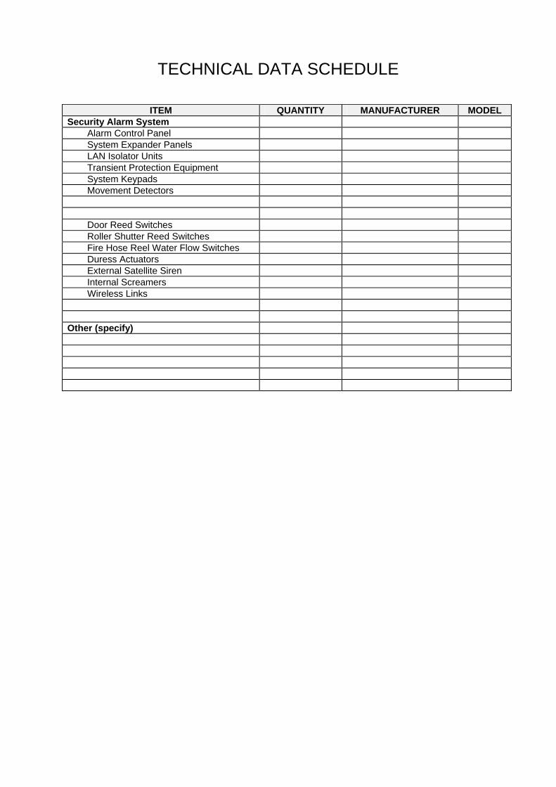
TECHNICAL DATA SCHEDULE
ITEM QUANTITY MANUFACTURER MODEL Security Alarm System
Alarm Control Panel System Expander Panels LAN Isolator Units Transient Protection Equipment System Keypads Movement Detectors Door Reed Switches Roller Shutter Reed Switches Fire Hose Reel Water Flow Switches Duress Actuators External Satellite Siren Internal Screamers Wireless Links
Other (specify)

APPENDIX 1B
PRICING SCHEDULE

Specification – School Security Systems Ver. 2009/1 Page: 2.3
PRICING SCHEDULE
ITEM COST Security System $ Cable/Conduit/Ducting etc $ Programming $ Training $ Testing and Commissioning $ Service and Warranty $ Drawings and Manuals $ Labour $ Other (detail) $
TOTAL TENDER PRICE $
NOTE: THE TOTAL TENDER PRICE MUST EQUAL THE SUM OF THE SCHEDULED COMPONENTS
Please provide details of hourly rates to be charged for works associated with this installation.
Hourly Rate $

Specification – School Security Systems Ver. 2009/1 Page: 2.4
PART 2 – CONDITIONS OF OFFER AND CONTRACT 2.1 Conditions of Offer _______________________________________________________6
2.1.1 Interpretation ..................................................................................................................... ...........................................................................................................................................6 2.1.2 Rules for Interpreting an Invitation................................................................................7 2.1.3 No Liability .......................................................................................................................7 2.1.4 Verbal Advice...................................................................................................................7 2.1.5 Previous Discussions/Undertakings.............................................................................7 2.1.6 Format of Offer ................................................................................................................7 2.1.7 Lodgement of Offer .........................................................................................................8 2.1.8 Prices................................................................................................................................8 2.1.9 Indemnity..........................................................................................................................8 2.1.10 Quality Assurance Requirements..................................................................................8 2.1.11 Quality of Goods..............................................................................................................8 2.1.12 Alternative Brands ..........................................................................................................8 2.1.13 Conflict of Interest...........................................................................................................9 2.1.14 Compliance with Code of Practice on Employment Obligations for Textile Clothing and Footwear Suppliers...................................................................................9 2.1.15 Site Visit ...........................................................................................................................9 2.1.16 Warranty ...........................................................................................................................9 2.1.17 Freedom of Information ..................................................................................................9 2.1.18 Competitive Neutrality ..................................................................................................10 2.1.19 Evaluation Process .......................................................................................................10 2.1.20 Non Conforming Offers ................................................................................................10 2.1.21 Further Information Requested by the Department...................................................10 2.1.22 Acceptance of Offers ....................................................................................................10 2.1.23 Post Offer Negotiations ................................................................................................11 2.1.24 Advertisements..............................................................................................................11
2.2 Conditions of Contract ___________________________________________________12 2.2.1 Interpretation .................................................................................................................12 2.2.2 Entire Agreement ..........................................................................................................13 2.2.3 Assignment and Subcontracting.................................................................................13 2.2.4 Negation of Employment and Agency ........................................................................14 2.2.5 Provision of Goods or Services...................................................................................14 2.2.6 Quality of Goods............................................................................................................14 2.2.7 Deficient Goods or Services ........................................................................................14 2.2.8 Inspection and Tests.....................................................................................................14 2.2.9 Packaging.......................................................................................................................15 2.2.10 Contractor’s Obligations ..............................................................................................15 2.2.11 Price................................................................................................................................15 2.2.12 Goods and Services Tax...............................................................................................15 2.2.13 Price Variations .............................................................................................................15 2.2.14 Payment Procedure.......................................................................................................16 2.2.15 Payment for Reduced Services....................................................................................16 2.2.16 Conflict of Interest.........................................................................................................17 2.2.17 Security and Access .....................................................................................................17 2.2.18 Confidential Information...............................................................................................17 2.2.19 Privacy Obligations.......................................................................................................17 2.2.20 Contract Variation .........................................................................................................18 2.2.21 Insurances......................................................................................................................18 2.2.22 Intellectual Property......................................................................................................19 2.2.23 Moral Rights...................................................................................................................19 2.2.24 Risk and Indemnity .......................................................................................................19 2.2.25 Compliance with Laws..................................................................................................20 2.2.26 Dispute Resolution........................................................................................................20 2.2.27 Termination....................................................................................................................20 2.2.28 Severability ....................................................................................................................20 2.2.29 Notices............................................................................................................................20

Specification – School Security Systems Ver. 2009/1 Page: 2.5
DOCUMENT CONTROL
VERSION DESCRIPTION / DETAILS OF AMENDMENT DATE 2003/1 Preliminary Draft March 2003 2004/1 Consultation Draft June 2004 2004/2 Initial Release August 2004 2007/1 Updated Throughout July 2007 2008/1 Draft – Changed EQ to DETA May 2008 2009/1 Approved June 2009

Specification – School Security Systems Ver. 2009/1 Page: 3.6
2.1 Conditions of Offer 2.1.1 Interpretation In these Conditions, unless the context otherwise requires, the following definitions apply:
“Arrangement” means a preferred supplier arrangement (PSA) or standing offer arrangement (SOA) for the provision of goods or services (as demand requires).
“Conditions” means the Department of Education, Training and the Arts
(DETA) Standard Conditions of Offer as outlined in this document.
“Contract” means the Contract formed upon acceptance of an Offer or
issuing of a Purchase Order, as specified in clause 2.1.22.
“Goods” means materials, plant or equipment supplied pursuant to an Arrangement or Contract.
“department” means the State of Queensland acting through the
Department of Education, Training and the Arts and its successors.
“Invitation” means the notice (written or verbal) given to prospective
Offerors indicating that Offers will be received for the supply of Goods or Services.
“Offer” means a response by an Offeror to an Invitation.
“Offeror” means a person or entity who submits an Offer.
“Officer” means an officer or employee of the State of Queensland,
or any other person engaged by the State in relation to an Invitation or any part thereof, or any of the employees of that person.
“Purchase Order” means the official order issued by the department which
forms a Contract between the Offeror and the department.
“Services” means the services supplied pursuant to an Arrangement or Contract.

Specification – School Security Systems Ver. 2009/1 Page: 3.7
2.1.2 Rules for Interpreting an Invitation Headings are for convenience only, and do not affect interpretation. The following rules shall apply in interpreting an Invitation, except where the context makes it clear that a rule is not intended to apply.
• A reference to: legislation (including subordinate legislation) is a reference to that legislation as
amended, re-enacted or replaced, and includes any subordinate legislation issued under it;
a clause is a reference to all of its sub-clauses; a clause or a sub-clause only is a reference to a clause or sub-clause within an
invitation; monetary references are references to Australian currency; a document or agreement, or a provision of a document or agreement, is a
reference to that document, agreement or provision as amended, supplemented, replaced or novated;
a person includes bodies corporate, unincorporated associations and partnerships, businesses, institutions and other entities; and
anything (including a right, obligation or concept) includes each part of it. • If an Invitation expressly or impliedly binds more than one person then it shall bind such
persons jointly and severally. • A singular word includes the plural, and vice versa. • A word which suggests one gender includes all genders. • If a word is defined, another part of speech of that word has a corresponding meaning.
2.1.3 No Liability This Invitation process is not intended to give rise to any legal or equitable relations between the department and an Offeror, until the Offeror has received a Purchase Order, in which case legal relations only exist between the department and the successful Offeror. The department may cancel, vary, supplement or supersede this Invitation process at any time, whether before or after the closing date. No Offeror shall be entitled to claim compensation or loss from the department for any matter arising out of the Invitation process.
2.1.4 Verbal Advice Verbal advice or information given or obtained in respect of the Invitation shall not constitute a warranty or a representation to the Offeror or prospective Offeror and shall not be binding on the department. The department shall be bound only by advice or information furnished to the Offeror in writing by the Purchasing Officer nominated in the Invitation document.
2.1.5 Previous Discussions/Undertakings On the release of an Invitation, any previous undertakings, representations, promises or conditions in respect of the subject matter of that Invitation shall not be binding on the department.
2.1.6 Format of Offer Offers will be received at the date and time, and at the address, specified in the Invitation. Offers will not be opened publicly. Offers must be submitted on the forms provided which are to be completed in full or the Offer may be rejected. Failure to do so or to provide the information in its entirety may result in non-consideration of the Offer. All pages that form the Offer are to bear the name of the Offeror. Covering letters or annexures should be avoided. If they are necessary, the salient points involved should be set out as briefly and concisely as possible. Descriptions of equipment, brochures and other details are to be restricted to actual items offered.

Specification – School Security Systems Ver. 2009/1 Page: 3.8
Conditions and specifications issued with the Invitation should be retained by the Offeror and should not be returned with the Offer.
2.1.7 Lodgement of Offer Offers may be submitted by facsimile or mailed in the manner and format specified in the Invitation. Every Offer shall be:
• signed by the person or entity making the Offer • directed to the department at the address specified in the Invitation.
It is the responsibility of the Offeror to ensure that Offers are received by the department before the time specified in the Invitation for the closing of Offers. The department may, at its sole discretion, reject an Offer delivered or received after the specified closing time for the receipt of Offers regardless of the reason for late delivery or receipt. Lodgement of an Offer in the manner specified in the Invitation will constitute an Offer by the Offeror to supply the Goods or Services for the price stated in the Offer.
2.1.8 Prices Prices offered shall:
• be in Australian Currency; • be inclusive of GST, if applicable, and show the GST amount separately; • include the costs of suitable packaging, delivery and installation where so required in the
Invitation; • if subject to fluctuation, include particulars of the price formula and all variables.
Trade and settlement discounts deductible from the prices offered shall be stated in the Offer. Offerors are encouraged to submit settlement discounts for early payment. All Goods or Services are required for prompt or early delivery. Offerors must state a definite time required for delivery of the Goods or Services after receipt of the Purchase Order(s), and the time so stated shall become the time of delivery under the Contract. 2.1.9 Indemnity All payments and royalties payable in respect of any letter, patent, design, trade mark or name, copyright or other protected right, shall be included by the Offeror in their Offer.
2.1.10 Quality Assurance Requirements 10.1. If the Invitation requires that Offers may only be made by potential Offerors who have, or who are able to obtain quality assurance to a specified standard, the Offeror will maintain quality assurance certification to that standard. 2.1.11 Quality of Goods All Goods, unless otherwise specified, shall be in accordance with Australian Standard specifications where such exist. Where an Australian Standard does not exist, the relevant ISO Standard shall apply. All Goods supplied shall be in new and unused condition and of recent origin unless the Invitation specifies otherwise.
2.1.12 Alternative Brands Where any specific brand or make is stated by the department in the Invitation, Offers may be submitted for Goods of other brands or makes which, in the opinion of the Offeror, are at least equivalent to the brand or make specified.

Specification – School Security Systems Ver. 2009/1 Page: 3.9
2.1.13 Conflict of Interest An Offer that:
• includes departmental employee(s) as key personnel; or • is submitted by departmental employee(s);
will not be accepted. Section 89 of the Criminal Code Act 1899 makes it an offence for a person employed in the public service to acquire or hold a private interest in a contract with a government agency where the employee works, whether directly or indirectly, other than a registered stock company with more than 20 stockholders. For the purpose of this clause, a departmental employee is an individual who receives or is entitled to receive salary or wages through the department’s payroll system.
2.1.14 Compliance with Code of Practice on Employment Obligations for Textile Clothing and Footwear Suppliers
The Queensland Government Code of Practice on Employment Obligations for Textile Clothing and Footwear Suppliers will apply to all contracts for the supply of textile articles, clothing, footwear, and related goods and components. Offerors must comply with the Queensland Government Code of Practice on Employment Obligations for Textile Clothing and Footwear Suppliers, and must provide evidence of compliance in the twelve months prior to the offer being lodged with applicable awards and statutory obligations relating to employees and outworkers when lodging an offer. Unless the information is provided, in the form of a statutory declaration, an offer will not be considered. All offerors must comply with the Queensland Government Code of Practice on Employment and Outwork Obligations for Textile Clothing and Footwear Suppliers. Lodgement of an offer will be evidence of the offeror’s agreement to comply with the Code and of their agreement to provide evidence of compliance with the Code when offering and access to all relevant records for the duration of any contract that may be awarded. If any offeror has failed to comply with the Code, their failure will be taken into account by the Client when considering this or any subsequent offer and may result in this or any subsequent offer being passed over.
2.1.15 Site Visit Where the Offer is for on-site Services, it is the responsibility of Offerors to visit the site and satisfy themselves of local conditions and facilities at the site.
2.1.16 Warranty An Offeror warrants that they:
• have read the Invitation and any associated documents; • understand the documents referred to; and • are satisfied that the information in the documents is correct and contains sufficient
details to make the Offer. An Offeror acknowledges that the department will rely on the representations and warranties made in an Offer and no variations shall be made to an Offer except in the manner herein provided.
2.1.17 Freedom of Information Offerors are advised that information provided in Offer documents may be subject to disclosure under the Freedom of Information Act 1992 (Qld) (“FOI Act”). The FOI Act grants members of the community a statutory right of access to documents in the possession of Queensland Government agencies, with certain exceptions and exemptions.

Specification – School Security Systems Ver. 2009/1 Page: 3.10
For more detailed information about the FOI Act, please contact:
Principal Policy Officer Legal and Administrative Law Branch Department of Education, Training and the Arts Telephone: (07) 3405 5675 Facsimile: (07) 3237 1650
2.1.18 Competitive Neutrality Offers submitted by a government owned business, a local government, or a State or Commonwealth agency or authority, must be priced to comply with the competitive neutrality policy of their respective jurisdiction.
2.1.19 Evaluation Process The Offer evaluation process shall involve a formal assessment of Offers received against the criteria listed in an Invitation. The Department reserves the right to shortlist Offerors during the evaluation process using any one or any combination of the evaluation criteria. The evaluation process may also involve discussions with Offerors, reference checks, product demonstrations or presentations from short-listed Offerors. The Department may negotiate a Customer Contract with one (1) or more Offeror/s.
2.1.20 Non Conforming Offers Failure to comply with all the requirements of the Invitation or the Conditions will result in an Offer being considered non-conforming. The department shall not be bound to consider non-conforming Offers.
2.1.21 Further Information Requested by the Department The Department may, at its absolute discretion and at any time:
• request clarification or additional information in writing from any Offeror; or • request the Offeror to attend a meeting with the Department.
If the Department requests the Offeror to attend a meeting pursuant to its Offer, the Offeror must be represented at the meeting by an officer(s) who has knowledge of technical, financial and contractual details of the Offer. The Offeror’s Offer will be deemed to include any information provided pursuant to this clause.
2.1.22 Acceptance of Offers The department is not bound to accept the lowest Offer. The department reserves the right to:
• accept one Offer, or more than one Offer, for the whole of its requirements; • accept separate Offers for any portion of its requirements; • accept one Offer, or more than one Offer, for any portion of its requirements; or • not accept any Offer received.
If the department accepts an Offer to Supply, a Contract to supply between the department and the successful Offeror will come into existence. No Offer shall be deemed to be accepted by the department until a Purchase Order has been received by the successful Offeror. Where an Offer is accepted under a departmental or other Government Arrangement, then the Contract shall be formed in accordance with the terms and conditions of that arrangement. Where purchases are made outside an Arrangement, then the Contract will be formed upon acceptance of an Offer or placement of a Purchase Order and will be constituted by the following documents:

Specification – School Security Systems Ver. 2009/1 Page: 3.11
Document 1 Purchase Order Document 2 Standard Conditions of Contract Document 3 Standard Conditions of Offer Document 4 Specifications of Invitation Document 5 Invitation Document 6 Offer
Where there arises an inconsistency or ambiguity between provisions in the different documents constituting the Contract, the order of precedence to resolve the inconsistency or ambiguity shall be from Document 1 to Document 6.
2.1.23 Post Offer Negotiations The department reserves the right to enter into post-offer negotiations with prospective Offerors.
2.1.24 Advertisements The successful Offeror will not make any public announcement or advertisement in any medium in relation to the awarding of any Arrangement or Contract entered into pursuant to the Invitation without the prior written approval of the department.

Specification – School Security Systems Ver. 2009/1 Page: 3.12
2.2 Conditions of Contract 2.2.1 Interpretation In these Conditions unless the context otherwise requires, the following definitions apply:
“Arrangement” means a preferred supplier arrangement (PSA) or standing offer arrangement (SOA) for the provision of goods or services (as demand requires).
“Conditions” the Department of Education, Training and the Arts
Standard Conditions of Contract as outlined in this document.
“Contract” the Contract formed upon acceptance of an Offer or issuing
of a Purchase Order, as specified in clause 2.2.2.
“Contractor” Includes the officers, employees, agents and authorised sub-contractors (and their employees and agents) of the Contractor.
“Contract Material” any material forming part of or constituting a deliverable that
is created, written or otherwise brought into existence by or on behalf of the department in the course of performing the services (called "new contract material"); and
any material that exists at the commencement date and is
incorporated into a deliverable (called "existing contract material").
“Department” means the State of Queensland acting through the
Department of Education, Training and the Arts and its successors.
“Goods” means materials, plant or equipment supplied pursuant to
an Arrangement or Contract.
“Intellectual Property” means all copyright, patents and all rights in relation to inventions, trade marks and designs.
“Invitation” The Invitation given to prospective Offerors inviting offers for
the supply of Goods or Services and includes the Specification.
“Moral Rights” Means the right of integrity of authorship, the right of
attribution of authorship and the right not to have authorship falsely attributed, more particularly as conferred by the Copyright Act 1968 (Cth), and rights of a similar nature anywhere in the world whether existing at the Commencement Date or which may come into existence on or after the Commencement Date.
“Offer” A response by an Offeror to an Invitation and includes an
Offer to Supply and a Standing Offer to Supply.
“Offeror” A person or entity who submits an Offer.
“Officer” An officer or employee of the State of Queensland, or any other person engaged by the State in relation to an Invitation or any part thereof, or any of the employees of that person.

Specification – School Security Systems Ver. 2009/1 Page: 3.13
“Personal Information” means the information or an opinion (including information or an opinion forming part of a database), whether true or not and whether recorded in a material form or not, about an individual whose identity is apparent or can reasonably be ascertained from the information or opinion.
“Project Manager” the officer appointed by the department to manage the
Contract and includes that person’s authorised representative.
“Purchase Order” means the official order issued by the department which
forms a Contract between the Offeror and the department.
“Services” means the services supplied pursuant to an Arrangement or Contract.
“Site” The land and buildings made available to the Contractor by
the department for the purposes of the provision of the Services.
“Specifications” The Item Description or Specification of requirements
outlined in the Invitation.
“Term” The period for which the Contract will be in effect, as specified in the Invitation.
In these Conditions:
• clause headings are inserted for ease of reference only and will not form part of, nor be used in the interpretation of, the Contract;
• words importing the singular will include the plural and vice versa, words importing a gender will include the other gender; and
• A reference to a person will be construed as a reference to an individual, firm, body corporate or other entity (whether incorporated or not), or, where a position is nominated, the individual occupying that position.
2.2.2 Entire Agreement No Offer shall be deemed to be accepted by the department until a Purchase Order has been received by the successful Offeror. Where an Offer is accepted under a departmental or other Government Arrangement, the contract shall be formed in accordance with the terms and conditions of that Arrangement. Where purchases are made outside an Arrangement, then the Contract will be formed upon acceptance of an Offer or placement of an Order will be constituted by the following documents:
• Document 1 Purchase Order • Document 2 Standard Conditions of Contract • Document 3 Standard Conditions of Offer • Document 4 Specifications of Invitation • Document 5 Invitation • Document 6 Offer
Where there arises an inconsistency or ambiguity between provisions in the different documents constituting the Contract, the order of precedence to resolve the inconsistency or ambiguity shall be from Document 1 to Document 6.
2.2.3 Assignment and Subcontracting The Contractor shall not assign nor subcontract any of the benefits or obligations under the Contract unless it has the prior written approval of the department. Approval to assign or sub-contract all or any of the Services will not relieve the Contractor from any liability or obligation under the Contract. The Contractor will be liable to the department for the acts

Specification – School Security Systems Ver. 2009/1 Page: 3.14
and omissions of sub-contractors and employees and agents of sub-contractors as if they were the acts or omissions of the Contractor.
2.2.4 Negation of Employment and Agency The Contractor will not:
• represent itself or allow itself to be represented as being an employee or agent of the department; or
• by virtue of the Contract be or become an employee or agent of the department.
2.2.5 Provision of Goods or Services The Contractor will provide the Goods or Services in accordance with the Contract for the Term in a proper manner and at the times specified in the Specifications or Purchase Order. The Contractor will:
• comply with the Specifications; • consult regularly with the department (through the Contract Supervisor and the Project
Manager) throughout the term of the Contract; and • act professionally at all times in the performance of the Contract.
The department will make available to the Contractor the assistance, if any, specified in the Specifications.
2.2.6 Quality of Goods All Goods, unless otherwise specified, shall be in accordance with Australian Standards where such exist. Where an Australian Standard does not exist, the relevant ISO Standard shall apply. All Goods supplied shall be in new and unused condition and of recent origin, unless the Invitation specified otherwise.
2.2.7 Deficient Goods or Services The Contractor will promptly supply or perform again any Goods or Services certified by the department as not being in accordance with the Contract. The department may, without derogating from any other right it may have on account of such unsatisfactory performance, defer payment of that part of an invoice relating to such Goods or Services until the Project Manager has certified that the re-supplied Goods or re-performed Services are in accordance with the Contract. If the Contractor fails to comply with the provisions of the Contract, the department reserves the right to arrange for the supply of Goods or Services from an alternative source. Any expenses incurred by the department as a result thereof will be a debt due and recoverable from the Contractor. All Goods or Services are required for prompt or early delivery. The Contractor must, after receipt of a Purchase Order, deliver the Goods or Services within the time required under the Contract. Time shall be of the essence in all cases. 2.2.8 Inspection and Tests The department reserves the right to inspect and test all Goods supplied. Where Goods fail any inspection or test, they will be rejected and the Contractor notified of their rejection and the reasons for the rejection. The Contractor shall replace, free of charge, all rejected Goods with Goods of a standard acceptable to the department. The Contractor shall at its own expense remove any rejected Goods from the department’s premises within 30 days of a written request by letter from the department and subject to any lien of the department. If, after 30 days, the rejected Goods have not been removed, the department may return the Goods freight forward, and at the Contractor’s risk, to the Contractor. All Goods which have been notified to the Contractor as rejected are held by the department at the Contractor’s risk.

Specification – School Security Systems Ver. 2009/1 Page: 3.15
2.2.9 Packaging Packaging and labelling of all Goods supplied and in particular poisons, drugs, chemicals, flammables, gases, volatiles, corrosives, explosives and goods of a dangerous nature, must comply with the provisions of the relevant Acts and Regulations which govern the packaging and handling of those Goods.
2.2.10 Contractor’s Obligations The Contractor will be responsible for the supply and performance of all personnel and equipment necessary for the proper supply or performance of the Goods or Services. The Contractor will:
• take all measures to protect people and property; • avoid unnecessary interference with the passage of people and vehicles; and • prevent nuisance and unreasonable noise and disturbance.
The Contractor shall comply with all Local Authority requirements. The Contractor will not publish the fact of, or details of, the Contract in any advertising medium without the department’s consent. The Contractor:
• warrants that it has the necessary skills and expertise to complete the Contract; and • will ensure that its employees, subcontractors and agents have the necessary skills and
expertise to perform those obligations of the Contractor which are allotted to them by the Contractor.
2.2.11 Price The Contractor will provide the Goods or Services for the price specified in the Purchase Order. Invoices must be completed in accordance with these Conditions.
2.2.12 Goods and Services Tax In this Contract, “GST” means a goods and services tax imposed by the Commonwealth of Australia. The Contractor acknowledges that in terms of the GST legislation it will, under the Contract, be a ‘supplier’ and may be required to remit GST to the Commissioner of Taxation. The Contractor will ensure that all invoices rendered to the department under the Contract are in a format that identifies any GST paid, and which permits the department to claim an input tax credit. The department will not pay any identified GST prior to 1 July 2000. The parties agree that the agreed prices for Goods or Services under the Contract are GST inclusive prices, and that the amount payable under the Contract shall not be varied by the amount of the GST.
2.2.13 Price Variations The Contractor is not entitled to increase prices once an Offer has been accepted by the department, other than for increases specified in the Offer. Where the Contractor’s Offer contains a price variation formula(e):
• price variations in accordance with the price formula(e) will not take effect until the department has given its written approval in accordance with this Clause;
• the Contractor must notify the department of the proposed price variations in accordance with the price variation formula(e) in the Contractor’s Offer;
• the Contractor must provide written documentary evidence satisfactory to the department which verifies the proposed variation;
• when the Contractor makes application for a price increase subject to that formula(e) such increase shall not come into effect until approved in writing by the department. The department may approve the price variation within 14 days of receiving the evidence referred to in this Clause;
• the department must advise the Contractor in writing, of the date on which the variation

Specification – School Security Systems Ver. 2009/1 Page: 3.16
will take effect and that date must not be more than 28 days after the department receives the evidence referred to in this Clause; and
• price variations effected pursuant to this Clause must not be effected more frequently than intervals of 3 months.
2.2.14 Payment Procedure The Contractor shall submit invoices to the Project Manager on a monthly basis, unless otherwise specified in writing by the department. The department will not have any obligation to pay the Contractor for any part of the Services until the department has been given a correctly rendered tax invoice. All invoices must:
• identify the title of the Services and the name of the relevant Project Manager; • identify the purchase order number and specific details pertaining to that order (if
applicable); • provide sufficient detail to enable the department to assess progress against targets (if
any) set out in the Specifications; and • where Services are charged on a time basis, be supported by records of times spent by
individual persons on the Services, verified by the Project Manager. Upon receipt of an invoice the department may require the Contractor to provide additional information to assist the department to determine whether or not an amount is payable. Subject to the Project Manager's certification that:
• the Services provided are of an acceptable standard; • the Services are completed; and • the Contractor's invoice is in accordance with the Contract.
the department will pay the amount due to the Contractor within thirty (30) days of receipt of the invoice (or such other period specified in the Schedule) or, if additional information is required by the department, within thirty (30) days (or such other period specified in the Schedule) after receipt of the additional information. If the department pays an invoiced amount to the Contractor, and it is subsequently found not to have been a correctly rendered tax invoice, the department will –
• pay any underpaid amount owed to the Contractor within thirty (30) days of receipt of a correctly rendered tax invoice (or such other period specified in the Schedule) or, if additional information is required by the department, thirty (30) days (or such other period specified in the Schedule) after receipt of the additional information; or
• deduct any overpaid amount owed to the department from the next invoiced payment or, if no other payment is due to the Contractor pursuant to the Contract, recover the amount from the Contractor as a debt due to the department.
Payment of money to the Contractor will not constitute an admission by the department that any of the Goods or Services have been performed in accordance with the Contract. Invoices and delivery dockets, properly completed, stating order number and particulars of Goods supplied, must be furnished at time of delivery.
2.2.15 Payment for Reduced Services The department may at any time serve a notice on the Contractor requiring the Contractor to decrease or omit any part of the Goods or Services. Following receipt of such a notice, the Contractor will reduce or cease work in accordance with the notice and immediately take all steps necessary to minimise the loss suffered by it as a result of the notice. Where the Services have been decreased or omitted under this clause, the department will pay the Contractor:
• fees for the Goods or Services performed as varied by the notice under this clause; and • any reasonable costs incurred by the Contractor which are directly attributable to the
reduction in the Goods or Services.

Specification – School Security Systems Ver. 2009/1 Page: 3.17
2.2.16 Conflict of Interest The Contractor warrants that, to the best of its knowledge, information and belief, at the date of the Contract, no conflict of interest exists or is likely to arise in the performance of its obligations under the Contract. If, during the term of the Contract, a conflict or risk of conflict of interest arises because of work undertaken for any person other than the department, the Contractor undertakes to notify the Project Manager immediately in writing of that conflict of interest or risk of it. The Contractor will take all reasonable measures to ensure that its employees, agents and subcontractors do not, during the term of the Contract, engage in any activity or obtain any interest which is in conflict with providing the Goods or Services to the department. Any such activity must be disclosed in writing to the Project Manager immediately. Where the Project Manager receives a notice of conflict of interest under this clause, the department may give the Contractor a notice to remedy the conflict.
2.2.17 Security and Access The Contractor will, when using the department’s premises or facilities (including the Site), comply with all reasonable directions and procedures as notified by the department or the Project Manager including those relating to security and to occupational health and safety which are in effect at those premises, facilities or Site. The Contractor will at all reasonable times give to the Project Manager or to any other persons authorised in writing by the department, access to premises occupied by the Contractor where the Services are being undertaken and will permit those persons to inspect the performance of the Contractor of its obligations under the Contract. The Project Manager and any other person authorised by the department, when at the Contractor's premises, will comply with all rules, directions and procedures as notified by the Contractor which are in effect at those premises including those relating to security and to occupational health and safety.
2.2.18 Confidential Information The Contactor will, and will ensure that its employees, agents and approved sub-contractors will, keep confidential any information obtained in the course of performing the Contract. If specified in the Specification, the Contractor’s employees, agents and approved sub-contractors will provide a confidentiality undertaking in a form acceptable to the department. In the event of a breach of the confidentiality undertaking entered into pursuant to this clause, the department may terminate the Contract by notice to the Contractor as of the date specified in the notice.
2.2.19 Privacy Obligations Where the Contactor has access to Personal Information in order to fulfil its obligations under the Contract, it must:
• where the Contractor is responsible for holding Personal Information, ensure that Personal Information is protected against loss and against unauthorised access, use, modification or disclosure and against other misuse;
• not use Personal Information other than for the purposes of the Contract, unless required or authorised by law;
• not disclose Personal Information without the written agreement of the Project Manager or any other persons authorised in writing by the department, unless required or authorised by law;
• ensure that only authorised personnel have access to Personal Information; • immediately notify the department if it becomes aware that a disclosure of Personal
Information is, or may be required or authorised by law; • make its employees, agents and subcontractors aware of the Contractor’s obligations
under this clause including, when requested by the department, requiring those employees, agents and subcontractors to promptly sign a Privacy Deed relating to Personal Information; and
• comply with such other privacy and security measures as the department reasonably advises the Contractor in writing from time to time.

Specification – School Security Systems Ver. 2009/1 Page: 3.18
The Contractor must immediately notify the department upon becoming aware of any breach of this clause.
2.2.20 Contract Variation Subject to these Conditions, no agreement or understanding that varies or amends the Contract will bind either party unless and until agreed to in writing by both parties.
2.2.21 Insurances The Contractor must have and maintain:
• insurance under the Worker’s Compensation and Rehabilitation Act 2003 to cover workers, eligible persons, self employed consultants, directors, trustees and partners; and
• public liability insurance to a minimum value of $5 Million. The insurances must be effected with an insurer approved by the department, include terms and conditions acceptable to the department, and be maintained for the duration of the Contract. The Contractor will –
• within 21 days of the date of the Purchase Order and before supplying or performing any of the Goods or Services; and
• upon request in writing at any time by the department, produce evidence to the department that the insurances required by this clause have been effected and maintained. If the Contractor fails to produce evidence of compliance with its insurance obligations to the satisfaction of the department, the department may effect and maintain the insurance, pay the premiums and deduct these payments from moneys due or becoming due to the Contractor from the department. The public liability insurance will include the department as co-insured but only in respect of the liability of the department arising out of the performance by the Contractor, or any subcontractors, of the Services. The public liability insurance will provide that the term `Insured' does apply to each of the persons comprising the insured in the same manner as if a separate policy had been issued to each of those persons in their name alone and the Insurer does waive all rights of subrogation or action which the Insurer may have or acquire against any of those persons, provided however that this clause will not be deemed to increase the limit of the Insurer's liability under the policy. The effecting and maintaining of insurance will not limit the liabilities or obligations of the Contractor under other provisions of the Contract. The Contractor shall ensure that the policies of insurance effected pursuant to this Contract contain provisions acceptable to the State that will –
• require the Insurer, whenever the Insurer gives to or serves upon the Contractor or a sub-contractor notice of cancellation or any other notice under or in relation to all or any of the interests insured under the policy, at the same time to give notice to the department in writing that the notice has been given to or served upon the Contractor or the sub-contractor;
• require that the Insurer will not cancel or vary the interest of all or any of the insured under the policy at the request of an insured party except upon the consent of all the co-insured; and
• provide that a notice of claim given to the insured by one insured shall be accepted by the Insurer as a notice of claim given to the Insurer by all the insured, as the case may require.
The Contractor shall inform the department in writing of any claim or of the occurrence of any event that may give rise to a claim under the policies of insurance effected pursuant to the Contract within 7 days thereof and shall ensure that the department is kept fully informed of subsequent actions and developments concerning the event or claim.

Specification – School Security Systems Ver. 2009/1 Page: 3.19
The Contractor shall ensure that each sub-contractor shall inform the Contractor in writing within 7 days of any claim or of any event that may give rise to a claim under the policies of insurance effected pursuant to the Contract.
2.2.22 Intellectual Property Unless otherwise specified in the Invitation, title to and intellectual property rights in all new contract material, including each and every stage of design and production of it, will on its creation, vest in the Department without need for further assurance. The agreement does not affect intellectual property rights in existing contract material but the Contractor grants, and must ensure that relevant third parties grant, to the Department a paid up non-exclusive, non-transferable licence:
• to use, reproduce, communicate to the public and adapt for its own use; • to perform any other act with respect to copyright; and • to manufacture, sell, hire or otherwise exploit a product or process or to provide a service
or to licence a third party to do any of those things in respect of; the existing contract material but only as part of the contract material (and any further development of that material).
2.2.23 Moral Rights Where the Contractor is an individual, the Contractor consents to any acts or omissions of the department in the exercise of rights or assignments granted under this clause that might otherwise constitute an infringement of the Contractor’s Moral Rights. Without limiting the above, the Contractor consents, in relation to the Contract Material:
• to being attributed as author of works comprised in the Contract Material in a form and manner acceptable to the department; and
• to the specific acts or omissions set out in the Schedule. Prior to an individual commencing work in respect of the Contract Material on behalf of the Contractor, the Contractor must obtain from that individual, in writing, and provide to the department, upon request:
• all consents, permissions and assignments to enable the department to exercise in full, without cost to the department and without impediment, the rights granted under this clause; and
• without limiting paragraph 23.3a), a consent to any act or omission (including the specific acts or omissions set out in the Schedule) which would otherwise infringe the Moral Rights of that individual. If requested by the department, such consent will be in a form specified by the department.
2.2.24 Risk and Indemnity The Contractor will be liable for loss or damage (including personal injury whether or not resulting in death) suffered by the department, its officers, servants or agents, arising from the unlawful or negligent acts or omissions of the Contractor, its employees, subcontractors or agents, in the course of the performance (or attempted or purported performance) of the Services. The Contractor releases and indemnifies the department and its officers, servants and agents from and against all actions whatsoever and howsoever arising which may be brought or made against any of them by any person, including the Contractor, arising from –
• any wilful or negligent act or omission of the Contractor or any person for whose conduct the Contractor is liable;
• any unlawful or negligent act or omission of the visitors, invitees or licensees of the Contractor;
• death, injury, loss or damage suffered by the Contractor, its employees, subcontractors or agents, or any of its visitors, invitees or licensees except where the death, injury, loss or damage is caused by the negligence or other wrongful act or omission of the department, its officers, servants or agents.
Specification – School Security Systems Ver. 2009/1 Page: 3.20
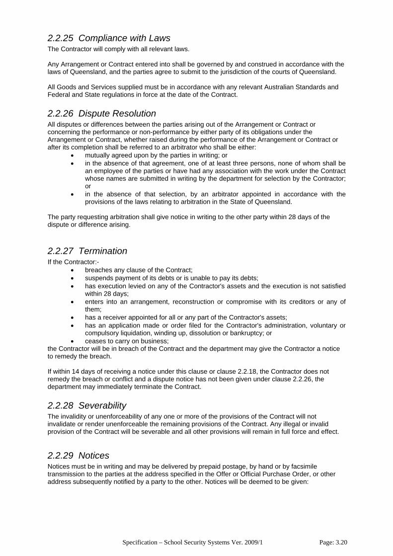
2.2.25 Compliance with Laws The Contractor will comply with all relevant laws. Any Arrangement or Contract entered into shall be governed by and construed in accordance with the laws of Queensland, and the parties agree to submit to the jurisdiction of the courts of Queensland. All Goods and Services supplied must be in accordance with any relevant Australian Standards and Federal and State regulations in force at the date of the Contract.
2.2.26 Dispute Resolution All disputes or differences between the parties arising out of the Arrangement or Contract or concerning the performance or non-performance by either party of its obligations under the Arrangement or Contract, whether raised during the performance of the Arrangement or Contract or after its completion shall be referred to an arbitrator who shall be either:
• mutually agreed upon by the parties in writing; or • in the absence of that agreement, one of at least three persons, none of whom shall be
an employee of the parties or have had any association with the work under the Contract whose names are submitted in writing by the department for selection by the Contractor; or
• in the absence of that selection, by an arbitrator appointed in accordance with the provisions of the laws relating to arbitration in the State of Queensland.
The party requesting arbitration shall give notice in writing to the other party within 28 days of the dispute or difference arising.
2.2.27 Termination If the Contractor:-
• breaches any clause of the Contract; • suspends payment of its debts or is unable to pay its debts; • has execution levied on any of the Contractor's assets and the execution is not satisfied
within 28 days; • enters into an arrangement, reconstruction or compromise with its creditors or any of
them; • has a receiver appointed for all or any part of the Contractor's assets; • has an application made or order filed for the Contractor's administration, voluntary or
compulsory liquidation, winding up, dissolution or bankruptcy; or • ceases to carry on business;
the Contractor will be in breach of the Contract and the department may give the Contractor a notice to remedy the breach. If within 14 days of receiving a notice under this clause or clause 2.2.18, the Contractor does not remedy the breach or conflict and a dispute notice has not been given under clause 2.2.26, the department may immediately terminate the Contract.
2.2.28 Severability The invalidity or unenforceability of any one or more of the provisions of the Contract will not invalidate or render unenforceable the remaining provisions of the Contract. Any illegal or invalid provision of the Contract will be severable and all other provisions will remain in full force and effect.
2.2.29 Notices Notices must be in writing and may be delivered by prepaid postage, by hand or by facsimile transmission to the parties at the address specified in the Offer or Official Purchase Order, or other address subsequently notified by a party to the other. Notices will be deemed to be given:
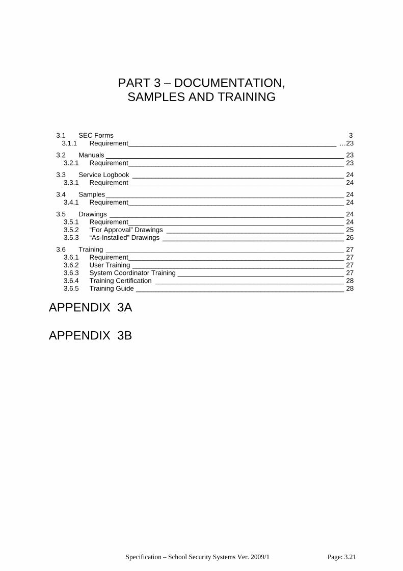
Specification – School Security Systems Ver. 2009/1 Page: 3.21
PART 3 – DOCUMENTATION, SAMPLES AND TRAINING
3.1 SEC Forms 3 3.1.1 Requirement_______________________________________________________ …23
3.2 Manuals _______________________________________________________________ 23 3.2.1 Requirement_________________________________________________________ 23
3.3 Service Logbook ________________________________________________________ 24 3.3.1 Requirement_________________________________________________________ 24
3.4 Samples_______________________________________________________________ 24 3.4.1 Requirement_________________________________________________________ 24
3.5 Drawings ______________________________________________________________ 24 3.5.1 Requirement_________________________________________________________ 24 3.5.2 “For Approval” Drawings _______________________________________________ 25 3.5.3 “As-Installed” Drawings ________________________________________________ 26
3.6 Training _______________________________________________________________ 27 3.6.1 Requirement_________________________________________________________ 27 3.6.2 User Training ________________________________________________________ 27 3.6.3 System Coordinator Training ____________________________________________ 27 3.6.4 Training Certification __________________________________________________ 28 3.6.5 Training Guide _______________________________________________________ 28
APPENDIX 3A APPENDIX 3B
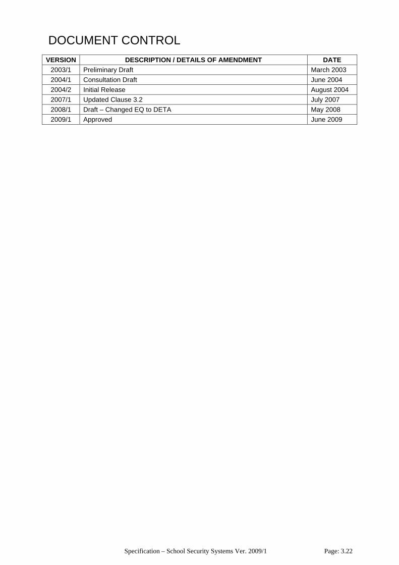
Specification – School Security Systems Ver. 2009/1 Page: 3.22
DOCUMENT CONTROL
VERSION DESCRIPTION / DETAILS OF AMENDMENT DATE 2003/1 Preliminary Draft March 2003 2004/1 Consultation Draft June 2004 2004/2 Initial Release August 2004 2007/1 Updated Clause 3.2 July 2007 2008/1 Draft – Changed EQ to DETA May 2008 2009/1 Approved June 2009
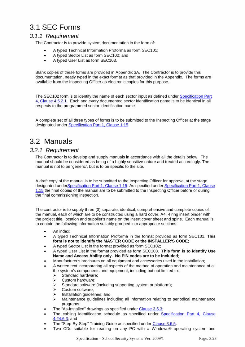
Specification – School Security Systems Ver. 2009/1 Page: 3.23
3.1 SEC Forms 3.1.1 Requirement
The Contractor is to provide system documentation in the form of:
• A typed Technical Information Proforma as form SEC101; • A typed Sector List as form SEC102; and • A typed User List as form SEC103.
Blank copies of these forms are provided in Appendix 3A. The Contractor is to provide this documentation, neatly typed in the exact format as that provided in the Appendix. The forms are available from the Inspecting Officer as electronic copies for this purpose.
The SEC102 form is to identify the name of each sector input as defined under Specification Part 4, Clause 4.5.2.1. Each and every documented sector identification name is to be identical in all respects to the programmed sector identification name.
A complete set of all three types of forms is to be submitted to the Inspecting Officer at the stage designated under Specification Part 1, Clause 1.15
3.2 Manuals 3.2.1 Requirement
The Contractor is to develop and supply manuals in accordance with all the details below. The manual should be considered as being of a highly sensitive nature and treated accordingly. The manual is not to be ‘generic’, but is to be specific to the site.
A draft copy of the manual is to be submitted to the Inspecting Officer for approval at the stage designated underSpecification Part 1, Clause 1.15. As specified under Specification Part 1, Clause 1.15 the final copies of the manual are to be submitted to the Inspecting Officer before or during the final commissioning inspection.
The contractor is to supply three (3) separate, identical, comprehensive and complete copies of the manual, each of which are to be constructed using a hard cover, A4, 4 ring insert binder with the project title, location and supplier's name on the insert cover sheet and spine. Each manual is to contain the following information suitably grouped into appropriate sections:
• An index; • A typed Technical Information Proforma in the format provided as form SEC101. This
form is not to identify the MASTER CODE or the INSTALLER’S CODE; • A typed Sector List in the format provided as form SEC102; • A typed User List in the format provided as form SEC103. This form is to identify Use
Name and Access Ability only. No PIN codes are to be included; • Manufacturer's brochures on all equipment and accessories used in the installation; • A written text incorporating all aspects of the method of operation and maintenance of all
the system’s components and equipment, including but not limited to: Standard hardware; Custom hardware; Standard software (including supporting system or platform); Custom software; Installation guidelines; and Maintenance guidelines including all information relating to periodical maintenance
programs. • The “As-Installed” drawings as specified under Clause 3.5.3; • The cabling identification schedule as specified under Specification Part 4, Clause
4.24.6.3; and • The “Step-By-Step” Training Guide as specified under Clause 3.6.5. • Two CDs suitable for reading on any PC with a Windows® operating system and

Specification – School Security Systems Ver. 2009/1 Page: 3.24
containing the following data: CD1 – Every page of this manual in PDF format such that each section is a
separate PDF file or a separate section of a single PDF file. CD2 – A full and correct upload of the final alarm system programming in a format
which can be loaded by or imported into the alarm system manufacturer’s PC utility program. For the following alarm system manufacture, a file suitable for the associated listed program is required: o Tecom Challenger Systems Latest version release of TITAN o Concept 1000 & 2000 Systems Inner Range IRP Upload/Download o Concept 3000 & 4000 Systems Inner Range WDirect Version 4.72
Where manufacturer's drawings are included in the manual, they are to be bound separately and cross-referenced in the manual text.
3.3 Service Logbook 3.3.1 Requirement
The Contractor is to supply the Inspecting Officer with a Service Logbook for the recording of all future system alterations and repairs. The Service Logbook is to be submitted at the stage designated under Specification Part 1, Clause 1.15.
3.4 Samples 3.4.1 Requirement
The Contractor is to supply the Inspecting Officer with equipment samples in accordance with all the details below. The supply of an equipment sample may be initiated by the Contractor or demanded by the Inspecting Officer at any stage during the life of the project, including tender submission, negotiations or construction.
The intention for the submission of samples is for the Contractor to gain the Inspecting Officer’s approval for the use of the equipment for the project.
Samples are to be:
• Complete in detail to enable the Inspecting Officer to determine whether the equipment samples comply with the requirements of the specification and whether they are suitable for their intended use and location;
• Labelled to identify their intended use and relation to these documents; • Held on site after inspection and used as a standard for acceptance or rejection of
subsequent production units; and • Returned to the supplier at the completion of the project.
The Contractor is to await the Inspecting Officer’s approval of the equipment samples before installation. Equipment installed which the Inspecting Officer determines as requiring prior sample approval and which has not been so approved, is to be removed by the Contractor and replaced with approved equipment at no cost.
3.5 Drawings 3.5.1 Requirement
The Contractor is to supply the Inspecting Officer with drawings in accordance with all the details below.

Specification – School Security Systems Ver. 2009/1 Page: 3.25
3.5.2 “For Approval” Drawings The intention for the submission of “For Approval” drawings is for the Contractor to gain the Inspecting Officer’s approval for the use of the equipment or scheme depicted on the drawings for the project.
The supply of “For Approval” drawings may be initiated by the Contractor or demanded by the Inspecting Officer at any stage during the life of the project, including tender submission, negotiations or construction.
“For Approval” drawings are to be:
• Submitted for all custom designed and/or constructed equipment; • Submitted for all equipment or schemes as specified on the Engineering Schedule or as
otherwise advised by the Inspecting Officer; • Submitted at the stage designated on the Engineering Schedule, or as otherwise advised
by the Inspecting Officer, and within sufficient time to permit modifications to be made without delaying the project, if such are deemed necessary by the Inspecting Officer, and to provide the Inspecting Officer with not less than seven (7) working days to make comment;
• Of sufficient quality and complete in detail to enable the Inspecting Officer to determine whether the depicted equipment or scheme complies with the requirements of the specification and is suitable for the intended use and location; and
• Marked or notated by the Inspecting Officer as: “Approved” The equipment or scheme may be used for this project; “Not Approved” The equipment or scheme cannot be used for this project. The
Contractor is to find alternatives and resubmit a new drawing for approval; or
“Resubmit” The Contractor is to undertake amendments as detailed by the Inspecting Officer and resubmit the drawing for approval.
The Contractor is to await the Inspecting Officer’s approval of the “For Approval” drawings before manufacture, installation or implementation. Equipment manufactured or work performed which the Inspecting Officer determines as requiring prior drawing approval and which has not been so approved, is to be removed by the Contractor and replaced with approved equipment/schemes at no cost.
3.5.2.1 “For Approval” Drawings of System Design Details Where specified on the Engineering Schedule, the Contractor is to provide “For Approval” drawings, detailing the proposed system design and the manufacturer’s approval of this design.
This information is to be in the form of a site plan or a schematic line diagram which clearly
identifies the following minimum information:
• The location of all Panels, LAN Isolators and Keypads; • LAN cable type; • LAN cable routes; • LAN cable lengths; • LAN cable shield earthing points; • LAN cable transient protection schemes; and • LAN cable identification numbers.
The manufacturer’s approval is to be provided by the manufacturer or their agent and is to be clearly identified on the plan or diagram.

Specification – School Security Systems Ver. 2009/1 Page: 3.26
3.5.3 “As-Installed” Drawings In accordance with Clause 3.2, the contractor is to supply “As-Installed” drawings for inclusion in the manuals.
Where specified on the Engineering Schedule, the Contractor is to provide a complete copy of all “As-Installed” drawings in AutoCAD® .DWD format on CD in each manual.
“As-Installed” drawings shall be:
• Drawn in ink on durable paper (pencil drawings will NOT be accepted); • Prepared by competent draftsmen (freehand drawings will NOT be accepted); • Prepared to comply with S.A.A. Standards for Engineering Drawing Practice, AS100 to
AS1109; • Drawn to the following scales 1:1, 1:5, 1:10, 1:20, for components and 1:50, 1:100 for
locations, except for wiring diagrams, which need not be to scale; and • Dimensioned in metric measurements.
3.5.2.2. Intruder Detection “As-Installed” drawings for Intruder Detection systems are to:
• Have an overall site plan identifying every building and: The location and identification / address of all Panels, LAN Isolators and Keypads; LAN cable type; LAN cable routes; LAN cable lengths; LAN cable shield earthing points; LAN cable transient protection schemes; LAN cable identification numbers; All wireless link transmitters and receivers; and All non-LAN, inter-building cabling runs.
Distinctly separate and individual identifications shall be made between cabling of differing purposes (LAN, detector, siren, etc.) and between cabling of differing installation method (overhead, underground, in pit system, etc.).
• Have an individual drawing for each building identifying the location, number, identification, type and associated input/output of all:
Detection devices; Sirens; Screamers; Panels; LAN Isolators; and Keypads.
3.5.2.3 CCTV “As-Installed” drawings for CCTV systems are to:
• Have an overall site plan identifying every building and the location, number, identification, type, orientation and associated input of:
The recording equipment; Every camera; Every camera enclosure; Camera support structures; Lighting equipment; Lighting support structures; and All inter-building cabling runs.
• Have an individual drawing for each building identifying the location, number,
identification, type, orientation and associated input of: The recording equipment; Every camera; Every camera power supply; Camera lenses; Camera enclosures;
Specification – School Security Systems Ver. 2009/1 Page: 3.27
“For Approval” drawings, which were prepared, submitted and approved prior to installation, may be accepted as the “As-Installed” drawings for the relevant portion of the works, provided they are accurate and have been amended to show all variations.
Reproductions of the contract drawings may be supplied by the Inspecting Officer, at current commercial rates, so that they may be amended to form the “As-Installed” drawings. However, it may be necessary to reword the notes and title blocks on the drawings so that they accurately depict the details of the work performed by the Contractor.
3.6 Training 3.6.1 Requirement
The Contractor is to train all users to a high degree of proficiency. The training shall be structured to provide two levels of expertise:
• User; and • System Coordinator.
Training shall be performed at the stage designated under Specification Part 1, Clause 1.15 on persons and at a time nominated by the School Principal.
3.6.2 User Training User training is to ensure that all users have knowledge of the following minimum elements of system operation:
• Knowledge of detection device operation; • Knowledge of where to locate resources to optimize their protection; and • Knowledge of where to locate furniture, equipment and decorations to optimize
protection and avoid false alarms.
and can consistently and proficiently perform all actions associated with:
• System and Area arming and disarming; • The acknowledgement of alarms; • The correct interpretation of keypad messages; • The silencing of sirens and screamers; and • The correct use of EWS equipment.
The Inspecting Officer will assess the training based on the trainee’s knowledge and ability to complete the above minimum tasks unaided.
3.6.3 System Coordinator Training System Coordinator training shall incorporate all the training required under Clause 3.6.2 plus additional understanding of the following elements of system operations:
• Understand the characteristics of an alarm history sufficient to identify the possible causes of an alarm;
• Understand how to maintain an environment for optimum protection and to avoid false alarms;
• Understand all types of alarms, their origin and their importance; • Understand the Sector List; • Understand User Types;
and the consistent and proficient performance of all actions associated with:
• Menu functions, in particular: Review past events; The creations, modification and deletion of Users, i.e.:
Specification – School Security Systems Ver. 2009/1 Page: 3.28
o Program names; o Program PIN codes; o Allocate User Types; o Allocate areas, etc.
The isolation of sectors and alarm inputs; Walk-testing an Area; and Setting the system time and date.
• Setting CCTV recording schedules; • Setting CCTV motion detection parameters; • Setting CCTV recording parameters such as speed and quality; • CCTV video searches and recovery techniques; • Backups and copying of single CCTV images and movies; and • Archiving.
System Coordinators are to have sufficient knowledge and ability to train people as either Users or other System Coordinators.
The Inspecting Officer will assess the training based on the trainee’s knowledge and ability to complete the above minimum tasks unaided:
3.6.4 Training Certification To certify the Contractor’s delivery of, and the School Principal’s satisfaction with the system training, the Contractor is to provide the Inspecting Officer with the original copy of the Training Certification Form, duly signed by the School Principal and the Contractor. This form is to be submitted at the stage designated under Specification Part 1, Clause 1.15.
A blank copy of this form is provided in Appendix 3B and is available from the Inspecting Officer as an electronic copy if necessary.
3.6.5 Training Guide The contractor is to provide a “step-by-step” Training Guide to assist training and as a quick reference guide on all aspects of the security system for the system Users and the System Coordinator.

APPENDIX 3A
SEC FORMS

STATE GOVERNMENT PROTECTIVE SECURITY SERVICE
SEC101 - TECHNICAL INFORMATION PROFORMA
SEC101 – Technical Information Proforma 26 November 2003 Revision 9
(To be completed and forwarded to SGPSS 48 hours prior to commissioning.)
FAX TO: STATE GOVERNMENT SECURITY PHONE: 3224 6666 FAX: 3224 4288
FAX FROM: PHONE: FAX:
CLIENT NAME: CLIENT CODE:
CLIENT ADDRESS:
CONTACT NAME: PHONE: FAX:
INSTALLATION CO: PHONE:
INSTALLED BY: SIGNED: DATE:
WARRANTY PERIOD: mths (6 months/12 months)
PIN CODES MASTER CODE: INSTALLER CODE:
SYSTEM INFORMATION PANEL TYPE:
PANEL LOCATION:
COMMUNICATION DETAILS PANEL PHONE NO:
FAX/ANSWER DEFEAT
(Y/N) *NO OF RINGS: *NO OF CALLS:
*SECURITY CODE: (*TECOM only) INSPECTING OFFICER: Printed Name______________________Signature_____________________
KEYPAD LOCATIONS EXPANDER LOCATIONS
1. 1.
2. 2.
3. 3.
4. 4.
5. 5.
6. 6.
7. 7.
8. 8.
9. 9.
10. 10.
11. 11.
12. 12.
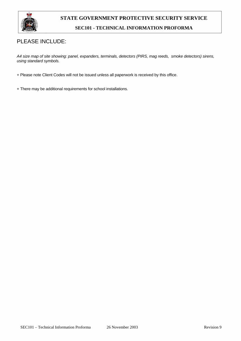
STATE GOVERNMENT PROTECTIVE SECURITY SERVICE
SEC101 - TECHNICAL INFORMATION PROFORMA
SEC101 – Technical Information Proforma 26 November 2003 Revision 9
PLEASE INCLUDE: A4 size map of site showing: panel, expanders, terminals, detectors (PIRS, mag reeds, smoke detectors) sirens, using standard symbols. + Please note Client Codes will not be issued unless all paperwork is received by this office. + There may be additional requirements for school installations.
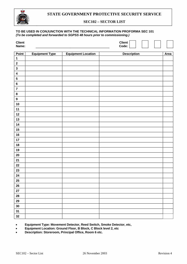
STATE GOVERNMENT PROTECTIVE SECURITY SERVICE
SEC102 – SECTOR LIST
SEC102 – Sector List 26 November 2003 Revision 4
TO BE USED IN CONJUNCTION WITH THE TECHNICAL INFORMATION PROFORMA SEC 101 (To be completed and forwarded to SGPSS 48 hours prior to commissioning.) Client Name:
Client Code:
Point Equipment Type Equipment Location Description Area1 2 3 4 5 6 7 8 9 10 11 12 13 14 15 16 17 18 19 20 21 22 23 24 25 26 27 28 29 30 31 32 • Equipment Type: Movement Detector, Reed Switch, Smoke Detector, etc, • Equipment Location: Ground Floor, B Block, C Block level 2, etc • Description: Storeroom, Principal Office, Room 6 etc.
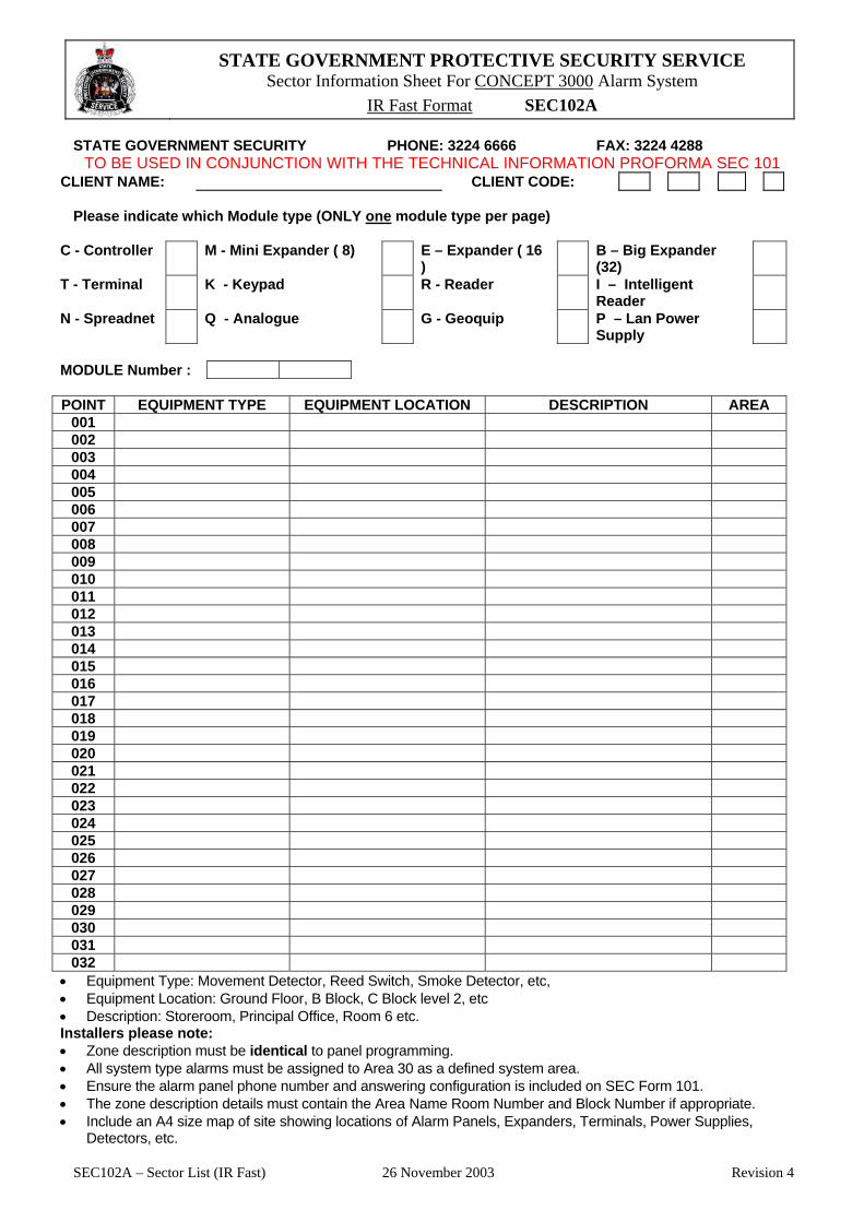
STATE GOVERNMENT PROTECTIVE SECURITY SERVICE Sector Information Sheet For CONCEPT 3000 Alarm System
IR Fast Format SEC102A
SEC102A – Sector List (IR Fast) 26 November 2003 Revision 4
STATE GOVERNMENT SECURITY PHONE: 3224 6666 FAX: 3224 4288 TO BE USED IN CONJUNCTION WITH THE TECHNICAL INFORMATION PROFORMA SEC 101
CLIENT NAME: CLIENT CODE: Please indicate which Module type (ONLY one module type per page)
C - Controller M - Mini Expander ( 8) E – Expander ( 16 )
B – Big Expander (32)
T - Terminal K - Keypad R - Reader I – Intelligent Reader
N - Spreadnet Q - Analogue G - Geoquip P – Lan Power Supply
MODULE Number :
POINT EQUIPMENT TYPE EQUIPMENT LOCATION DESCRIPTION AREA
001 002 003 004 005 006 007 008 009 010 011 012 013 014 015 016 017 018 019 020 021 022 023 024 025 026 027 028 029 030 031 032
• Equipment Type: Movement Detector, Reed Switch, Smoke Detector, etc, • Equipment Location: Ground Floor, B Block, C Block level 2, etc • Description: Storeroom, Principal Office, Room 6 etc. Installers please note: • Zone description must be identical to panel programming. • All system type alarms must be assigned to Area 30 as a defined system area. • Ensure the alarm panel phone number and answering configuration is included on SEC Form 101. • The zone description details must contain the Area Name Room Number and Block Number if appropriate. • Include an A4 size map of site showing locations of Alarm Panels, Expanders, Terminals, Power Supplies,
Detectors, etc.
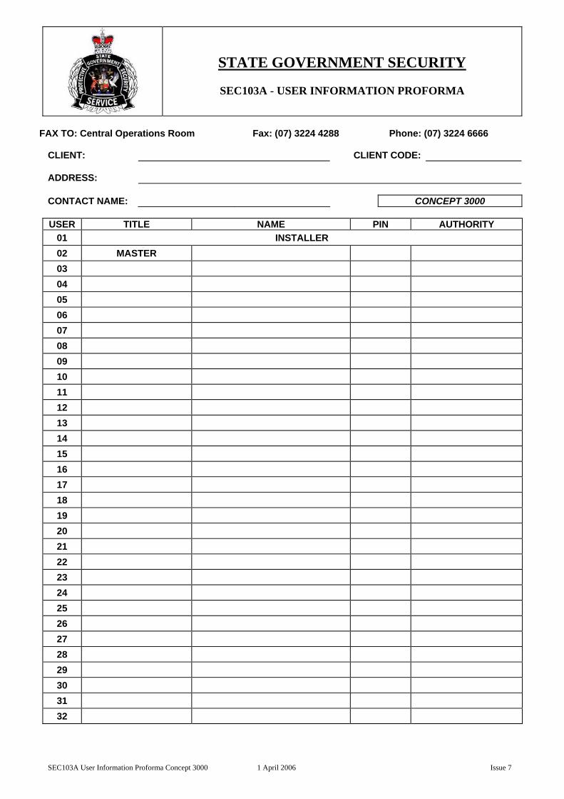
STATE GOVERNMENT SECURITY
SEC103A - USER INFORMATION PROFORMA
SEC103A User Information Proforma Concept 3000 1 April 2006 Issue 7
FAX TO: Central Operations Room Fax: (07) 3224 4288 Phone: (07) 3224 6666
CLIENT: CLIENT CODE: ADDRESS: CONTACT NAME: CONCEPT 3000 USER TITLE NAME PIN AUTHORITY
01 INSTALLER 02 MASTER 03 04 05 06 07 08 09 10 11 12 13 14 15 16 17 18 19 20 21 22 23 24 25 26 27 28 29 30 31 32

STATE GOVERNMENT SECURITY
SEC103B - USER INFORMATION PROFORMA
SEC103B User Information Proforma Concept 2000 1 April 2006 Issue 7
FAX TO: Central Operations Room Fax: (07) 3224 4288 Phone: (07) 3224 6666
CLIENT: CLIENT CODE: ADDRESS: CONTACT NAME: CONCEPT 2000 USER TITLE NAME PIN AUTHORITY
00 MASTER 01 INSTALLER 02 03 04 05 06 07 08 09 10 11 12 13 14 15 16 17 18 19 20 21 22 23 24 25 26 27 28 29 30 31

STATE GOVERNMENT SECURITY
SEC103C - USER INFORMATION PROFORMA
SEC103C User Information Proforma Tecom Challenger 1 April 2006 Issue 7
FAX TO: Central Operations Room Fax: (07) 3224 4288 Phone: (07) 3224 6666
CLIENT: CLIENT CODE: ADDRESS: CONTACT NAME: TECOM CHALLENGER USER TITLE NAME PIN AUTHORITY
50 MASTER 01 02 03 04 05 06 07 08 09 10 11 12 13 14 15 16 17 18 19 20 21 22 23 24 25 26 27 28 29 30

APPENDIX 3B TRAINING CERTIFICATION FORM
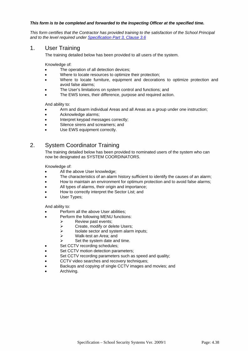
Specification – School Security Systems Ver. 2009/1 Page: 4.38
This form is to be completed and forwarded to the Inspecting Officer at the specified time. This form certifies that the Contractor has provided training to the satisfaction of the School Principal and to the level required under Specification Part 3, Clause 3.6 1. User Training
The training detailed below has been provided to all users of the system. Knowledge of: • The operation of all detection devices; • Where to locate resources to optimize their protection; • Where to locate furniture, equipment and decorations to optimize protection and
avoid false alarms; • The User’s limitations on system control and functions; and • The EWS tones, their difference, purpose and required action. And ability to: • Arm and disarm individual Areas and all Areas as a group under one instruction; • Acknowledge alarms; • Interpret keypad messages correctly; • Silence sirens and screamers; and • Use EWS equipment correctly.
2. System Coordinator Training
The training detailed below has been provided to nominated users of the system who can now be designated as SYSTEM COORDINATORS. Knowledge of: • All the above User knowledge; • The characteristics of an alarm history sufficient to identify the causes of an alarm; • How to maintain an environment for optimum protection and to avoid false alarms; • All types of alarms, their origin and importance; • How to correctly interpret the Sector List; and • User Types;
And ability to: • Perform all the above User abilities; • Perform the following MENU functions:
Review past events; Create, modify or delete Users; Isolate sector and system alarm inputs; Walk-test an Area; and Set the system date and time.
• Set CCTV recording schedules; • Set CCTV motion detection parameters; • Set CCTV recording parameters such as speed and quality; • CCTV video searches and recovery techniques; • Backups and copying of single CCTV images and movies; and • Archiving.

Specification – School Security Systems Ver. 2009/1 Page: 4.39
3. Certification
The following persons have received training to the level required to act as SYSTEM COORDINATORS and I am satisfied that ALL persons have received adequate training in the use of the alarm system as detailed above.
Name Position
School Principal I certify that all training requirements have been completed.
Contractor
• 2 days after deposit in the mail with postage prepaid;
• immediately upon delivery by hand; or
• immediately upon an apparently successful facsimile transmission of the entire notice being noted by the sender's transmitter, prior to 5.00pm on any business day in Queensland, and if after 5.00pm the notice will be deemed to be given at 9.00am on the next business day.
Specification – School Security Systems Ver. 2009/1 Page: 4.40
PART 4
ELECTRONIC SECURITY TECHNICAL SPECIFICATION
4.1 Scope__________________________________________________________________44 4.1.1 Requirement ....................................................................................................................44 4.1.2 Extent of Work.................................................................................................................44 4.1.3 Additional Work ...............................................................................................................44 4.1.4 Standards ........................................................................................................................45 4.1.5 Approvals.........................................................................................................................45
4.2 Monitoring Station ________________________________________________________45 4.2.1 Requirement ....................................................................................................................45
4.3 Alarm Control Panel_______________________________________________________45 4.3.1 Requirement ....................................................................................................................45 4.3.2 System Firmware.............................................................................................................46
4.4 Telecommunications Service ________________________________________________46 4.4.1 Requirement ....................................................................................................................46
4.5 System Programming _____________________________________________________47 4.5.1 Requirement ....................................................................................................................47 4.5.2 Input Programming..........................................................................................................47 4.5.3 Area Programming ..........................................................................................................48 4.5.4 User Programming ..........................................................................................................48 4.5.5 Communications Programming.......................................................................................49
4.6 LAN Communications System _______________________________________________50 4.6.1 Requirement ....................................................................................................................50 4.6.2 Cabling / Media................................................................................................................50 4.6.3 LAN Isolator Units ...........................................................................................................50 4.6.4 Shielding and Earthing ....................................................................................................50 4.6.5 Transient Protection ........................................................................................................50
4.7 System Expander Panels___________________________________________________51 4.7.1 Requirement ....................................................................................................................51
4.8 System Keypads _________________________________________________________51 4.8.1 Requirement ....................................................................................................................51 4.8.2 External Keypads ............................................................................................................51
4.9 Intelligent Door Controllers__________________________________________________51 4.9.1 Requirement ....................................................................................................................51 4.9.2 Features ..........................................................................................................................51 4.9.3 Operation.........................................................................................................................52
4.10 Access Control Card Readers _______________________________________________53 4.10.1 Requirement ....................................................................................................................53
4.11 Access Control Cards _____________________________________________________53 4.11.1 Requirement ....................................................................................................................53
4.12 Electric Locks____________________________________________________________53 4.12.1 Requirement ....................................................................................................................53 4.12.2 Type.................................................................................................................................53
4.13 Cable Transfer Devices ____________________________________________________54 4.13.1 Requirement ....................................................................................................................54
4.14 Connections for Access Control Functions _____________________________________54 4.14.1 Requirement ....................................................................................................................54 4.14.2 Standard ..........................................................................................................................54 4.14.3 Door Lock ........................................................................................................................54 4.14.4 Door Status Signals.........................................................................................................54 4.14.5 Request-To-Exit (REX) Signals.......................................................................................55
Specification – School Security Systems Ver. 2009/1 Page: 4.41
4.15 Movement Detectors ______________________________________________________55 4.15.1 Requirement ....................................................................................................................55 4.15.2 Type.................................................................................................................................55 4.15.3 Location ...........................................................................................................................55 4.15.4 Position............................................................................................................................55 4.15.5 Mounting..........................................................................................................................56 4.15.6 Cabling ............................................................................................................................56 4.15.7 Labelling ..........................................................................................................................56 4.15.8 Operation Indication L.E.D.(s) .........................................................................................56 4.15.9 Nuisance Alarms .............................................................................................................57
4.16 Door Contacts ___________________________________________________________57 4.16.1 Requirement ....................................................................................................................57 4.16.2 Type.................................................................................................................................57 4.16.3 Standard ..........................................................................................................................57 4.16.4 Location ...........................................................................................................................57 4.16.5 Position............................................................................................................................57 4.16.6 Installation .......................................................................................................................57 4.16.7 Cabling ............................................................................................................................58 4.16.8 Labelling ..........................................................................................................................58 4.16.9 Nuisance Alarms .............................................................................................................58
4.17 Fire Hose Reel Water Flow Switches__________________________________________58 4.17.1 Requirement ....................................................................................................................58 4.17.2 Type.................................................................................................................................59 4.17.3 Location ...........................................................................................................................59 4.17.4 Position............................................................................................................................59 4.17.5 Installation .......................................................................................................................59 4.17.6 Cabling ............................................................................................................................59 4.17.7 Labelling ..........................................................................................................................59 4.17.8 Nuisance Alarms .............................................................................................................60
4.18 Duress Actuators _________________________________________________________60 4.18.1 Requirement ....................................................................................................................60 4.18.2 Type.................................................................................................................................60 4.18.3 Standard ..........................................................................................................................60 4.18.4 Location ...........................................................................................................................60 4.18.5 Position............................................................................................................................60 4.18.6 Installation .......................................................................................................................61 4.18.7 Cabling ............................................................................................................................61 4.18.8 Labelling ..........................................................................................................................61 4.18.9 Nuisance Alarms .............................................................................................................61
4.19 Sirens and Screamers _____________________________________________________61 4.19.1 Requirement ....................................................................................................................61 4.19.2 Type.................................................................................................................................61 4.19.3 Standard ..........................................................................................................................62 4.19.4 Location ...........................................................................................................................62 4.19.5 Position............................................................................................................................62 4.19.6 Installation .......................................................................................................................62 4.19.7 Cabling ............................................................................................................................62 4.19.8 Operation.........................................................................................................................63 4.19.9 Labelling ..........................................................................................................................63
4.20 Wireless Links ___________________________________________________________63 4.20.1 Requirement ....................................................................................................................63
4.21 Mains Power Supply Equipment _____________________________________________63 4.21.1 Requirement ....................................................................................................................63 4.21.2 240 Volt General Purpose Outlets (GPOs) .....................................................................64
4.22 DC Power Supply Equipment________________________________________________64 4.22.1 Requirement ....................................................................................................................64 4.22.2 Stand-by Batteries...........................................................................................................64 4.22.3 Operational Batteries.......................................................................................................64 4.22.4 Auxiliary DC Power Supplies...........................................................................................64
4.23 System Programming and Administration Software_______________________________65 4.23.1 Requirement ....................................................................................................................65
Specification – School Security Systems Ver. 2009/1 Page: 4.42
4.23.2 Interface...........................................................................................................................65 4.23.3 Software ..........................................................................................................................65 4.23.4 Printer ..............................................................................................................................65 4.23.5 Cabling ............................................................................................................................65
4.24 Cabling_________________________________________________________________65 4.24.1 Requirement ....................................................................................................................65 4.24.2 Standards ........................................................................................................................66 4.24.3 Detection Device Cabling ................................................................................................66 4.24.4 Siren and Screamer Cabling ...........................................................................................66 4.24.5 Access Control Function Cabling ....................................................................................66 4.24.6 LAN Media.......................................................................................................................66 4.24.7 PC and Printer Interface Cabling.....................................................................................67 4.24.8 Installation Method ..........................................................................................................67
4.25 Conduits________________________________________________________________67 4.25.1 Requirement ....................................................................................................................67 4.25.2 Standard ..........................................................................................................................67 4.25.3 General............................................................................................................................68 4.25.4 External ...........................................................................................................................68 4.25.5 Underground....................................................................................................................68 4.25.6 Un-enclosed Spaces or Construction..............................................................................68
4.26 Approved Labelling _______________________________________________________69 4.26.1 Requirement ....................................................................................................................69 4.26.2 Detection Devices, Sirens and Screamers......................................................................69 4.26.3 240 Volt GPOs.................................................................................................................69 4.26.4 Fire Hose Reels...............................................................................................................69 4.26.5 LAN Cable Numbering Ferrules ......................................................................................69
APPENDIX 4A APPENDIX 4B APPENDIX 4C

Specification – School Security Systems Ver. 2009/1 Page: 4.43
DOCUMENT CONTROL
VERSION DESCRIPTION / DETAILS OF AMENDMENT DATE 2003/1 Preliminary Draft March 2003 2004/1 Consultation Draft June 2004 2004/2 Initial Release August 2004 2007/1 Updated July 2007
2008/1 Draft Added Access Control Function; Changed EQ to DETA Multiple general technical updates and amendments.
May 2008
2009/1 Approved June 2009
Specification – School Security Systems Ver. 2009/1 Page: 4.44
4.1 Scope 4.1.1 Requirement
The contractor is to provide a complete, operative, “turn-key” electronic security installation which integrally performs access control, intruder detection and alarm signaling functions.
Important Note: This part includes specifications for a wide range of equipment. Refer to the Engineering Schedule for site and project specific requirements.
4.1.2 Extent of Work The work comprises the supply of all necessary equipment and materials, installation, commissioning, servicing and maintenance of an electronic security system which includes the following:
• An Alarm Control Panel; • System Programming; • A LAN communications system; • LAN Isolator Units; • LAN Transient Protection Equipment; • Intrusion Detection Equipment, including:
System Expander Panels; System Keypads; Detection Devices; Duress Alarm Switches; and Sirens and Screamers.
• Access Control Equipment, including: Intelligent Door Controllers; Access Control Card Readers; Access Control Cards; Electric Locks; Cable Transfer Devices; and Door Contacts.
• Auxiliary Power Supply Equipment; • System programming and administration software; • Cabling and equipment connection; • Provision of and system connection to a dedicated PSTN telephone line; • Provision of General Purpose Outlets from essential services supply; • Cable support and enclosure systems; • Supply of site specific Technical Manuals as required under Specification Part 3; • Supply of a System Logbook as required under Specification Part 3; • Supply of an Operator’s Manual as required under Specification Part 3; • Training of nominated personnel as required under Specification Part 3; • Progress inspections as required under Specification Part 1; • Pre-commissioning testing by the Contractor; • A final commissioning inspection as required under Specification Part 1; • Rectification of all defects; • A warranty as required under Specification Part 1; • Breakdown and regular service maintenance checks as required under Specification Part
1; • Making good any damage; and • Work outside normal working hours as instructed by the Inspecting Officer.
4.1.3 Additional Work Provide any additional work or parts that, in the opinion of the Inspecting Officer, are necessary to provide a complete operative installation in accordance with the requirements.
Specification – School Security Systems Ver. 2009/1 Page: 4.45
4.1.4 Standards
All work and equipment is to comply with the following minimum requirements:
• Australian Standards, including but not limited to AS2201, AS/NZS1367 and AS3000; • The manufacturer’s instructions and/or recommendations; and • All requirements detailed below.
4.1.5 Approvals The Inspecting Officer shall approve all equipment and work. Any equipment or work considered by the Inspecting Officer as not meeting one or more consideration may be defected and identified for replacement and/or rectification at the Contractor’s expense.
4.2 Monitoring Station 4.2.1 Requirement
When authorised by the Inspecting Officer, alarm signaling from the site is to be monitored at the State Government Security Central Operations Room (COR) in Brisbane using the communications format specified on the Engineering Schedule.
4.3. Alarm Control Panel 4.3.1 Requirement
Unless otherwise noted on the Engineering Schedule, it is required that a single, unique alarm
control panel be installed. The alarm control panel is to meet the following minimum requirements:
• Be uniquely identifiable to the monitoring station by a single client code; • Be capable of supporting the number of intruder detection sectors as detailed on the
Engineering Schedule. Each sector shall be capable of being: Individually identifiable as a number and name using the administration software or
any system keypad; Individually supervised and capable of reporting SECURE, ALARM and TAMPER
conditions; Individually selected for testing using the administration software or any system
keypad to display each of the above conditions; Individually selected for isolation using the administration software or any system
keypad so that secure, alarm and tamper conditions are not processed by the system.
• Be capable of supporting the number of intruder detection areas as detailed on the Engineering Schedule. Areas shall be capable of being:
Armed or disarmed under one instruction individually or in a group; Individually programmed for separate entry and exit delay times; Individually programmed to allow any number of sectors to be grouped into the area;
• Be capable of supporting the number of system keypads as detailed on the Engineering Schedule;
• Be capable of supporting the number of access controlled doors as detailed on the Engineering Schedule. Each door shall be capable of being:
Individually identifiable as a number and name using the administration software or any system keypad;
Individually supervised and capable of reporting DOOR FORCED, DOOR AJAR and TAMPER conditions (minimum);
• Be capable of uniquely recognising and handling a minimum of 500 individual PIN codes
Specification – School Security Systems Ver. 2009/1 Page: 4.46
or access control cards; • Be capable of uniquely identifying each PIN user or cardholder by both their first and last
name in a 16 character (minimum) text string; • Incorporate an integral dialer and remote monitoring signal transmission equipment. The
dialer and/or transmission equipment shall: Have integrated transient protection devices; Have the capacity to dial a minimum of 2 telephone numbers of minimum 15 digits
length each and incorporate pauses between digits; Have both the following signal transmission formats:
o Ademco Contact ID (Large); and o Inner Range Fast.
Be capable of reporting all the conditions detailed under Specification Clause 4.5.5 from all equipment and devices using the communications format specified on the Engineering Schedule:
• Have the ability for all programming to be performed and all system operations to be controlled both:
Locally o At any keypad; or o By using the manufacturer’s specific PC software; and
Remotely over the PSTN by the specific manufacturer’s software package used by State Government Security.
• Be capable of storing an event history; • Be capable of temporarily isolating inputs. The panel shall automatically re-enable any
isolated inputs on the opening of an associated area so as to not allow inputs to remain isolated indefinitely.
• Be fitted with a back-up battery to permit full system operation in the event of mains power failure in accordance with Specification Clause 4.22;
• Be fitted with a suitable firmware version in accordance with Specification Clause 4.3.2; • Be fitted with a dual port (minimum), RS232 interface for the connection of a system
printer and computer in accordance with Specification Clause 4.23; and • Be fitted with the maximum possible memory expansion option.
4.3.2 System Firmware All security system components are to be supplied and fitted with the manufacturer’s latest firmware version. System firmware is to be suitable for the purposes of:
• System operation as specified; • Local administration using the software specified in Specification Clause 4.23; • Monitoring by State Government Security; and • All remote support services offered by State Government Security.
4.4 Telecommunications Service 4.4.1 Requirement The contractor is to perform all work and pay all associated fees for the provision of a dedicated PSTN telephone line and its connection to the alarm control panel dialer. This service is to be dedicated for the exclusive use of the alarm system and is not to be shared with any other device or used for any other purpose. The connection socket for the telephone service is to be mounted inside the alarm panel housing. The contractor is to provide a transient protection system which is additional to the integrated devices on the alarm control panel PCB and which provides enhanced protection from damage due to transients induced or injected onto the telephone line. Transient protection equipment is to be manufactured or approved by the alarm system manufacturer and installed in accordance with the manufacturer’s instructions within the alarm control panel enclosure.

Specification – School Security Systems Ver. 2009/1 Page: 4.47
4.5 System Programming 4.5.1 Requirement The contractor is to perform system programming using good security system programming practice and to the approval of the Inspecting Officer. System programming shall be:
• Complete; • Correct; • Concise; and • Contain no redundancies.
4.5.2 Input Programming 4.5.2.1 Sector Inputs
Each sector input shall be individually defined with a unique name which clearly and unambiguously identifies the location and type of the connected security device. Identical sector identification names are not acceptable. The identified location of the security device shall match the location’s final identification name and number. Location identifications shall not simply be taken off a construction plan. Programming detail shall be not be subjective or interpretative and shall use compass headings in preference to any other means of location identification.
Examples of un-acceptable identifications are:
• Office Detector • Library Detector 4 • R3 Far Detector • Tractor Shed Roller Door 2 • Manual Arts Tamper • Performing Arts Smoke
Examples of acceptable identifications are:
• Administration Office PIR • Library Main Area Western PIR • Classroom F3 Southern PIR • Tractor Shed North Roller Door Reed Switch • Manual Arts External Keypad Tamper Switch • Performing Arts Fire Alarm System
System programming shall instruct the system to perform the correct processing, operations and signaling of sector events for each sector used. Remote communications of input events shall be performed in accordance with Specification Clause 4.5.5. All communicated input events shall be logged to the system’s event history memory and sent to the system printer and computer interface for recording and future auditing. All other functions shall be performed as detailed on the following table.
DEVICE TYPE SOUND AREA SIREN KEYPAD MESSAGE Intruder Detectors
Alarm Restore Tamper
YES NO NO
YES NO YES
Duress Buttons Alarm Restore Tamper
NO NO NO
YES NO YES
Fire Alarm Systems Alarm Restore Tamper
NO NO NO
YES NO YES
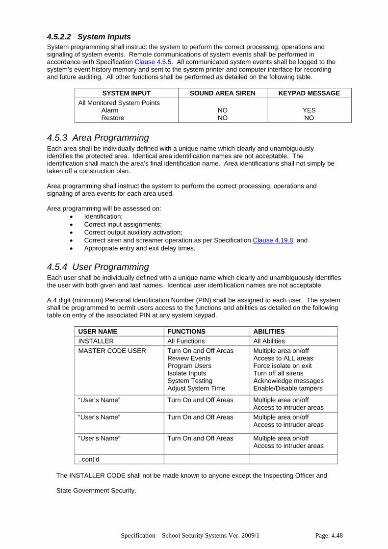
Specification – School Security Systems Ver. 2009/1 Page: 4.48
4.5.2.2 System Inputs System programming shall instruct the system to perform the correct processing, operations and signaling of system events. Remote communications of system events shall be performed in accordance with Specification Clause 4.5.5. All communicated system events shall be logged to the system’s event history memory and sent to the system printer and computer interface for recording and future auditing. All other functions shall be performed as detailed on the following table.
SYSTEM INPUT SOUND AREA SIREN KEYPAD MESSAGE All Monitored System Points
Alarm Restore
NO NO
YES NO
4.5.3 Area Programming Each area shall be individually defined with a unique name which clearly and unambiguously identifies the protected area. Identical area identification names are not acceptable. The identification shall match the area’s final identification name. Area identifications shall not simply be taken off a construction plan. Area programming shall instruct the system to perform the correct processing, operations and signaling of area events for each area used. Area programming will be assessed on:
• Identification; • Correct input assignments; • Correct output auxiliary activation; • Correct siren and screamer operation as per Specification Clause 4.19.8; and • Appropriate entry and exit delay times.
4.5.4 User Programming Each user shall be individually defined with a unique name which clearly and unambiguously identifies the user with both given and last names. Identical user identification names are not acceptable. A 4 digit (minimum) Personal Identification Number (PIN) shall be assigned to each user. The system shall be programmed to permit users access to the functions and abilities as detailed on the following table on entry of the associated PIN at any system keypad.
USER NAME FUNCTIONS ABILITIES INSTALLER All Functions All Abilities MASTER CODE USER Turn On and Off Areas
Review Events Program Users Isolate Inputs System Testing Adjust System Time
Multiple area on/off Access to ALL areas Force isolate on exit Turn off all sirens Acknowledge messages Enable/Disable tampers
“User’s Name” Turn On and Off Areas Multiple area on/off Access to intruder areas
“User’s Name” Turn On and Off Areas Multiple area on/off Access to intruder areas
“User’s Name” Turn On and Off Areas Multiple area on/off Access to intruder areas
..cont’d
The INSTALLER CODE shall not be made known to anyone except the Inspecting Officer and
State Government Security.

Specification – School Security Systems Ver. 2009/1 Page: 4.49
The MASTER CODE shall not be issued to any person as a personal PIN code but solely used for system administration by persons trained to the level of System Coordinator in accordance with Specification Part 3, Clause 3.6.3.
4.5.5 Communications Programming The system shall be programmed to dial the monitoring station and report all the following conditions using the communications format specified on the Engineering Schedule:
• Each Sector Alarm Restore from alarm Tamper Restore from tamper Isolated (including by user number or event) De-isolated (including by user number or event)
• Each Intruder Detection Area Armed (including by user number or event) Disarmed (including by user number or event) Enable/Disable processing of tamper alarms
• Each 24 Hour Armed Area (System, Duress, Fire, etc.) Armed (including by user number or event) Disarmed (including by user number or event) Enable/Disable processing of tamper alarms Area should be armed warning
• Alarm Control Panel Cabinet tamper Restore from cabinet tamper External siren tamper (where used for external siren) Restore from external siren tamper (where used for external siren) Mains failure Restore from mains failure Low battery LAN fuse failure Detector fuse failure Battery test failure Time report on a WEEKLY basis between the hours of 2400 and 0500 any one day
of the week. Module substitution
• Each Keypad Cabinet tamper Restore from cabinet tamper Too many code attempts Communications failure Duress alarm
• Each Expander Cabinet tamper Restore from cabinet tamper External siren tamper (where used for external siren) Restore from external siren tamper (where used for external siren) Mains failure Restore from mains failure Low battery LAN fuse failure Detector fuse failure Battery test failure Communications failure
• Each Intelligent Door Controller Cabinet tamper Restore from cabinet tamper Mains failure Restore from mains failure Low battery LAN fuse failure Detector fuse failure
Specification – School Security Systems Ver. 2009/1 Page: 4.50
Battery test failure Communications failure Door forced open (per door) Door lock tamper (per door)
4.6 LAN Communications System 4.6.1 Requirement The contractor is to supply and install all materials and equipment and perform all necessary work to produce a highly secure and stable LAN communications system. LAN media, installation and connection is to be in precise accordance with the system manufacturer's instructions and recommendations. All LAN media is to be run unterminated or joined in places other than those allowed under Specification Clause 4.6.5. Field termination or joining of LAN media or any supporting earth cable will not be accepted.
4.6.2 Cabling / Media Unless otherwise specified, all LAN media which runs between modules in different buildings is to be optical fibre. The Contractor is to supply and install all required optical fibre and matching interfaces, modems, media converters, etc. to meet the requirement. LAN media to local system keypads is to be copper data cable, run from the closest module. Other than for local system keypads, installations are not permitted to mix different LAN media types.
All LAN media and installation shall fully comply with Specification Clause 4.24.6.
In addition to the mandatory cabling provider registration requirements, all work for the provision of an optical fibre LAN system is to be performed by persons who meet the competency standards for optical fibre installation and repair work.
4.6.3 LAN Isolator Units
Where a copper LAN system is installed the Contractor is to supply and install LAN Isolator Units to provide enhanced LAN communications and protection. The number and location of the LAN isolator units shall be as recommended or approved by the manufacturer. LAN isolator enclosure tamper switches shall be fitted to detect lid removal or enclosure removal. Where a LAN isolator is mounted adjacent the alarm control panel or an expander panel, connect the LAN isolator enclosure tamper switches with the adjacent panel’s enclosure tamper switch such that operation of any switch initiates a tamper alarm. Otherwise, connect the LAN isolator tamper switches to a dedicated sector input, so that each device can be individually addressed in system programming, on the alarm control panel or an expander on the LAN 1 uplink side.
4.6.4 Shielding and Earthing For copper LAN installations, particular attention is to be paid to the correct connection of the protective, earthed shield and the provision, continuity and connection of earthing systems to ensure that the entire LAN installation is protected from damaging electrical influences and data transmissions are protected from disruption.
4.6.5 Transient Protection Where a copper LAN system is installed the Contractor is to provide a comprehensive transient protection system to protect all LAN modules from damage due to lightning and other harmful influences. Transient protection equipment is to be manufactured or approved by the alarm system manufacturer and installed in accordance with the manufacturer’s instructions within the module enclosures.
Specification – School Security Systems Ver. 2009/1 Page: 4.51
4.7 System Expander Panels 4.7.1 Requirement
Supply and install expander panels as necessary to meet the requirements of the Engineering Schedule. Only 16 or 32 sector input system expander panels are to be installed. Unless otherwise noted on the Engineering Schedule, the contractor shall determine the number and location of system expander panels and shall allow for the efficient cabling, connection and operation of the system with an absolute minimum of externally run detector cabling. The locations of expander panels shall take into account any known future school developments and facilitate straightforward system expansion in the future.
4.8 System Keypads 4.8.1 Requirement
Supply and install LCD keypads in locations detailed on the Engineering Schedule. All keypads shall be identical in appearance and function. Each keypad shall be tamper protected to detect attempts to open the keypad or remove it from the mounting surface.
4.8.2 External Keypads
Where external keypads are specified on the Engineering Schedule, these keypads are to be installed in Rittal EB series protective enclosures with the following minimum features:
• Maintained IP66 rating; • Keyed cylinder lock which is:
Keyed to the school’s master key system (where existing); Keyed alike with all such enclosures on site;
• Tamper protected to detect attempts to remove the enclosure from the mounting surface. Such protection may be provided via:
A dedicated tamper switch connected to a dedicated sector input, so that each device can be individually addressed in system programming; or
An extension of the keypad’s integral tamper switch to meet the requirement for tamper protection of both the keypad and the enclosure.
The contractor is to supply the Inspecting Officer with the number of keys to the external keypad enclosure(s) as specified on the Engineering Schedule. Each key shall be individually numbered using number stamps or by deep engraving.
4.9 Intelligent Door Controllers 4.9.1 Requirement
Supply and install intelligent door controllers as necessary to meet the access control requirements of the Engineering Schedule. Unless otherwise noted on the Engineering Schedule, the contractor shall determine the number and location of door controllers and shall allow for the efficient cabling, connection and operation of the system with an absolute minimum of externally run cabling. Door controllers are to be co-located with other LAN modules such as the alarm control panel or system expander panels, where existing.
4.9.2 Features
Each door controller is to have the following minimum input and output facilities for each controlled door:
• A dedicated and separately fused relay switched 12V DC (nominal) power output for the electric lock associated with the door. The relay output is to have a minimum contact rating of 1Amp;
• A dedicated and separately fused 12V DC power supply output for card readers associated with the door;
• Dedicated outputs for data signals to/from card readers associated with the door; and
Specification – School Security Systems Ver. 2009/1 Page: 4.52
• Separate and dedicated inputs for “request-to-exit” (REX) and “request-to-entry” (REN) signals from REX or REN switches associated with the door.
Door controllers are to have the capability for two card readers to be associated with a single door to permit the installation of both an entry card reader and an exit card reader for a single door. Each card reader and door is to be independently addressed in system programming and identified by means of a unique plain English description.
4.9.3 Operation Intelligent door controllers are to operate in the following manner:
• Each door controller is to be capable of automatically switching the status of any associated door at different times of the day, based on parameters passed on from the alarm control panel. The following access criteria modes are required:
Access - door is unlocked, no card entry required; Secure - door is locked, a successful card attempt is required for valid entry. Door
re-secures after access; and Pending access - door is locked (Secure), but switches automatically to Access
upon first successful access attempt during a particular time period. • On the presentation of a card to a reader connected to an intelligent door controller, the
controller is to check validity of access based on ALL the following criteria: Correct facility code; Authorised card in database; Authorised reader (door); Authorised associated intruder detection area control; and Authorised time of day.
• The door controller is to unlock a controlled door within 0.5 seconds of the presentation of a valid card at a reader associated with the door;
• Door controllers are to monitor the condition of and access attempts on each door and report all events to the alarm control panel for further processing, data storage, signaling or enunciation;
• Separate alarm messages are to be transmitted to the alarm control panel for each of the following alarm conditions from each door:
Door forced open; Door open too long (ajar); Door not locked; Invalid access attempt; and Door lock being tampered.
• A "Restore" message is to be transmitted to the alarm control panel when the door is re-locked after the following door alarm conditions:
Door forced open; Door open too long (ajar); and Door not locked.
• Should communications with the alarm control panel fail: All door controllers are to continue to operate without performance degradation; The isolated door controller is to continue making access decisions with all access
attempts, valid or otherwise, and all alarm activations buffered internally to the isolated door controller. An internal activity buffer of at least 100 events is required; and
The door controller is to immediately transfer the buffered activity events to the central controller when the communications link is re-established.
• Door controllers are to be fitted with automatic restart facilities to enable them to resume processing following a power and backup failure;
• Door controllers are to be fitted with "watchdog" hardware and software to enable them to restart and resume normal processing, should the processing system ever be corrupted; and
• Should any door controller fail or stop operation for any reason only those doors associated with the failed door controller are to be affected.

Specification – School Security Systems Ver. 2009/1 Page: 4.53
4.10 Access Control Card Readers 4.10.1 Requirement
Supply and install new access control card readers as specified in the Engineering Schedule.
Access control card readers are to have the following minimum specification:
• 26 bit (minimum) Wiegand proximity Type; • Operate from the dedicated 12V DC (nominal) power supply output from the associated
intelligent door controller; • Be of weatherproof construction and resistant to vandalism; • Incorporate a sounder for user feedback of access attempt or door open too long (ajar)
condition; • Incorporate a multi-colour LED for user feedback of door or associated intruder detection
area status. • Be available in a range of faceplate colours
4.11 Access Control Cards 4.11.1 Requirement
The contractor is to supply the Inspecting Officer with the number of access control cards as specified on the Engineering Schedule.
Access control cards are to have the following minimum specification:
• All access control encoding data is to be invisible to the naked eye; • All card data is to be encrypted so that the card data bears no resemblance to the
number printed on the card; • It shall be impossible to decipher, copy or alter access control data stored on the card
using any readily available equipment; • All cards supplied shall be encoded with a facility code, unique to this site. The facility
code shall not be in use at any other location in the world; • Additional cards shall be available ex-stock. Ex-stock is defined as additional cards
being available and delivered on site within 24 hours of request; • Additional card supplies must be numbered according to the client specifications, made
known at the time of order. Cards supplied with manufacturer determined card numbers are not acceptable.
4.12 Electric Locks 4.12.1 Requirement
Supply and install electric door locks as necessary to meet the access control requirements of the Engineering Schedule.
4.12.2 Type Unless as specified below or otherwise noted on the Engineering Schedule, the contractor is to determine the type of door lock to suit the particular door, hardware and application.
Electric locking of typical wooden pedestrian access doors is to be performed by Lockwood 3500 series or approved equal electric mortise locks with the following functions or features:
• Be of a style which matches other door locks and meets other architectural requirements; • Be of a model and form which matches the door and door frame; • Have separate latchbolts for door locking and door deadlatching; • Be fitted with an electrical locking solenoid which operates on 12V DC; • Be integrally fitted with a flywheel diode to suppress back EMF and protect the locking
solenoid;
Specification – School Security Systems Ver. 2009/1 Page: 4.54
• Be of Fail-Secure type, except where specifically required otherwise under the Building Code of Australia (BCA);
• Be fitted with the following control hardware only: Internal
An exit handle which is free and opens the door at all times. External
A controlled circular knob to open the door except when locked by the solenoid; A momentary action hard key cylinder to open the door at all times. Cylinder is to
be keyed to the school’s keying system. • Be integrally fitted with two switches to provide a single, logical AND output for both door
closed and door secure conditions. If a reed switch magnet is required to be fitted in the door jamb for this purpose, this magnet is to be a fully concealed type, fitted in accordance with Specification Clause 4.10.6.1.
• Be integrally fitted with a microswitch on the internal lock hub, monitoring use of the free internal door handle. This switch is to always activate before the door condition output changes state and in sufficient time for the access control system to process this signal before the door condition signal.
• Be fitted complete with a matching striker plate in the door frame;
4.13 Cable Transfer Devices 4.13.1 Requirement
All cabling for the transfer of power and signals to/from electric mortise locks is to be performed via Lockwood LC88xx series or approved equal armoured and chrome plated cable transfer devices. Other than this transfer device, all cabling is to be concealed internally within the wall cavity, door frame and the door.
4.14 Connections for Access Control Functions 4.14.1 Requirement
Supply and install all equipment and materials and perform all work to connect the various elements of the system for the required access control functions.
4.14.2 Standard All material and work is to be in accordance with the manufacturer’s instructions or recommendations. All cabling and cable installation shall fully comply with Specification Clause 4.24.
4.14.3 Door Lock Door locks are to be connected to the dedicated and specific relay output of the intelligent door controller which controls the locking or otherwise of the associated door. Unless integrally fitted in the door lock, a flywheel diode is to be installed at the lock to suppress back EMF.
4.14.4 Door Status Signals The logical AND output from the switches monitoring door closed and door secure conditions of each door is to be connected to the dedicated and specific input of the intelligent door controller which monitors the condition of the associated door. Any End-Of-Line (EOL) resistors required for this function are to be located within the cavity in the door created for the door lock.
Specification – School Security Systems Ver. 2009/1 Page: 4.55
4.14.5 Request-To-Exit (REX) Signals The microswitch monitoring the free internal door handle of each door is to be connected to the dedicated and specific Request to Exit (REX) signal input of the intelligent door controller for the associated door. Any End-Of-Line (EOL) resistors required for this function are to be located within the cavity in the door created for the door lock.
4.15 Movement Detectors 4.15.1 Requirement
Supply and install movement detectors for the performance of electronic intruder detection functions.
4.15.2 Type Unless otherwise noted on the Engineering Schedule, the contractor shall determine the type of detector, selected solely from the list of approved detectors included as Appendix 4A. The selection criteria for approved detectors is available on request. Tenderers wishing to offer alternative detectors to those approved must provide the following documentation with the submission and/or tender:
• Manufacturer’s documentation verifying satisfaction of all selection criteria; and • A sample detector for examination and analysis.
4.15.3 Location The locations requiring protection are specified on the Engineering Schedule.
When selecting the detector to be used for a specified location, the Contractor shall consider the following minimum issues:
• Location purpose; • Location environment under all climatic conditions; • Location size; and • Manufacturer’s recommendations.
The contractor shall refer to Specification Part 1, Clause 1.13 and verify the architectural design and expected environment to ensure this requirement is met.
4.15.4 Position The Contractor shall determine the final position of all detectors such that optimum protection is provided for the specified location with full coverage of all possible entry and egress points while causing minimum interference to all activities within the location. Where the Engineering Schedule identifies particular sites within the location to be included in the detection pattern, the detector position shall permit the above coverage including such sites.
When determining the final position of a detector in a specified location, the Contractor shall consider the above requirements and the following minimum issues:
• It shall not be possible for the Detector to be subject to interference; • It shall not be possible for the Detection pattern to be subject to interference; • It shall not be possible for the Detector to be subject to draughts or environmental
disturbances; and • Detector position shall not be contrary to manufacturer’s recommendations.
Some example detail is included under Appendix 4B. The contractor shall refer to Specification Part 1, Clause 1.13 and verify the architectural design and position of all equipment and fixtures to ensure this requirement is met. Detectors shall be deemed subject to interference where they are positioned within reach of any person standing on the floor or any adjacent structure or architectural feature providing physical support.
Specification – School Security Systems Ver. 2009/1 Page: 4.56
Detectors shall be deemed to have their detection pattern subject to interference where equipment, fixtures, fittings or fixed furniture items obstruct any part of the detection pattern or provide support for any other item which would obstruct any part of the detection pattern. Detectors shall be deemed to be subject to draughts or environmental disturbances where they are installed in any room or location which is not fully enclosed or subject to any natural ventilation or, at their closest point, they are positioned within:
• 30 centimetres of any open-able window; • 40 centimetres of any air-conditioning or forced air ventilation supply or return opening;
or • 40 centimetres from the blades of any ceiling fan.
4.15.5 Mounting Detectors shall be securely mounted in accordance with the manufacturer’s instructions or recommendations and in a manner which ensures that optimum protection is provided for the specified location. Ceiling mount detectors are to be horizontally mounted and an approved mounting method shall be employed where the ceiling is unsuitable.
Ceilings considered unsuitable for direct mounting of detectors includes but is not restricted to:
• Sloping or raked ceilings; • Ceilings supported by exposed trusses and beams; • Excessively high ceilings; and • Ceilings constructed from material with poor mechanical strength such as fiberglass tiles.
Mounting of detectors directly on suspended ceiling support frames is also not acceptable.
In such cases, acceptable mounting methods include but are not restricted to:
• Corrective, angled block sections to rectify the detector mounting angle to the horizontal; or
• Wall or ceiling mount brackets specifically designed and produced by the detector manufacturer; or
• Steel sheeting riveted to the suspended ceiling support frames in the corner of the suspended tile.
Some example detail is included under Appendix 4B. The contractor shall refer to Specification Part 1, Clause 1.13 and verify the architectural design and construction methods and materials to ensure this requirement is met.
4.15.6 Cabling All cabling and cable installation shall fully comply with Specification Clause 4.24. Each detector is to be individually connected to a separate and distinct sector input so that each device can be individually addressed in system programming.
4.15.7 Labelling Each detector shall be individually identified by its sector input number with an approved label in accordance with Specification Clause 4.26 affixed at the detector. Detectors which incorporate a separate base for mounting and terminating the detector shall have the label affixed to the base. Other detectors shall have the label affixed to the mounting surface adjacent to the detector. Labels shall not be affixed directly on the detector.
4.15.8 Operation Indication L.E.D.(s) Where detectors incorporate one or more indicating L.E.D.(s), the Contractor shall ensure that these L.E.D.(s) are operational for all inspections. L.E.D.(s) are to be disabled only under instruction from the Inspecting Officer. The Contractor may be instructed to re-enable any detection L.E.D.(s) found disabled before such an instruction from the Inspecting Officer has been issued. Such instruction may occur verbally during the commissioning inspection and/or included with the Defects List. L.E.D.(s) are to disabled immediately the instruction is received.
Specification – School Security Systems Ver. 2009/1 Page: 4.57
4.15.9 Nuisance Alarms Any detector considered by the Inspecting Officer as exhibiting nuisance alarms during the warranty period may be defected and identified for repair, replacement and/or relocation at the Contractor’s expense.
4.16 Door Contacts 4.16.1 Requirement
Supply and install door contacts for the performance of electronic intruder detection and access control functions.
4.16.2 Type Door contacts shall be magnetic reed switches of type as laid down on the Engineering Schedule. Where type of door contact is not identified on the Engineering Schedule, door contacts shall be concealed magnetic reed switches for pedestrian access doors and heavy-duty roller door type magnetic reed switches for larger equipment access doors and roller grilles.
4.16.3 Standard Magnetic reed switches shall comply with Australian Standard AS2201.3 -- 1991, Section 4.10.
4.16.4 Location The locations requiring protection are specified on the Engineering Schedule.
4.16.5 Position The Contractor shall determine the final position of all door contacts such that optimum protection is provided for the specified location while causing minimum interference to all activities within the location.
When determining the position of a door contact in a specified location, the Contractor shall consider the above requirements and the following minimum issues:
• An alarm condition shall not be initiated prior to the door moving 5mm but shall be initiated prior to the door moving 50 mm. (AS2201.3 -- 1991, Section 4.10.2.1);
• It shall not be possible for the door contact to be subject to interference; • Door contact position shall not result in interference or disruption to the magnet’s
magnetic field; and • Door contact position shall not be contrary to manufacturer’s recommendations.
4.16.6 Installation Where it is specified that door contacts be installed on a door with multiple leaves, one door contact shall be installed on each door leaf.
4.16.6.1 Concealed Concealed magnetic door contacts shall be installed in a manner as recommended by the manufacturer and such that it is not possible to identify the presence of the door contact. Installation shall not result in interference or disruption to the magnet’s magnetic field. Both contact and magnet shall be securely fixed or glued in place such that it is impossible to remove either element without the use of a tool.
Specification – School Security Systems Ver. 2009/1 Page: 4.58
4.16.6.2 Roller Door Type Roller door type door contacts shall be installed in a manner as recommended by the manufacturer and such that it is not possible to identify the presence of the door contact from the unsecured area side of the door. Installation shall not result in interference or disruption to the magnet’s magnetic field. Purpose designed and built metal brackets shall be employed where spacing of magnet and/or contacts is necessary.
Magnet mounting screws shall be either:
• Vibration proof and completely concealed when viewed from the unsecured area side of the door or;
• “Blind” head, metal thread screws, vibration proof washers and nuts with the screw head in the unsecured area side of the door or;
• Screw head, metal thread screws, vibration proof washers and nuts with the screw head in the unsecured area side of the door and permanently treated to prevent screw removal.
All cable protective flexible metal serving shall be securely fixed to the floor, wall and/or the door frame in order to severely restrict the possibility of accidental damage. Such fixings shall be either:
• Correct sized metal saddles spaced a maximum of 5 centimeters apart or; • Metal “hat” section extrusion covering the entire length of the serving.
All metal surfaces subject to corrosion are to be painted or treated to prevent corrosion.
4.16.7 Cabling All cabling and cable installation shall fully comply with Specification Clause 4.24. Except where multiple door contacts are installed on a single door or on a door with multiple leaves, each door contact shall be individually connected to a separate and distinct sector input so that each device can be individually addressed in system programming.
Where multiple door contacts are installed on a single door or on a door with multiple leaves, those door contacts are to be connected such that that door appears as a single, separate and distinct sector input and;
• An intrusion alarm is generated on the operation of either door contact; and • A tamper alarm is generated on a tamper condition from either door contact.
All cable terminations and termination resistors are to be either entirely concealed or enclosed within junction boxes. Cable terminations made or enclosed in conduit is unacceptable.
4.16.8 Labelling Each door contact shall be individually identified by its sector input number with an approved label in accordance with Specification Clause 4.26 affixed to the wall surface adjacent to the device. Labels shall not be affixed directly on the device.
4.16.9. Nuisance Alarms Any door contact considered by the Inspecting Officer as exhibiting nuisance alarms during the warranty period may be defected and identified for repair, replacement and/or relocation at the Contractor’s expense.
4.17 Fire Hose Reel Water Flow Switches 4.17.1 Requirement
Supply and install fire hose reel water flow switches to detect the operation of such equipment in the locations detailed on the Engineering Schedule. Each fire hose shall be fitted with its own, dedicated water flow switch.
Specification – School Security Systems Ver. 2009/1 Page: 4.59
Supply and install all associated pipes and fittings to permit the correct installation and operation of the water flow switches in accordance with this specification and the manufacturer’s instructions.
A DETA Standard Document Drawing provides some detail for this work. This detail is included under Appendix 4C. Where applicable, reference is made on the Engineering Schedule.
4.17.2 Type Water flow switches shall be System Sensor WFDT series or approved equal with the following minimum requirements:
• UL listed and rated for installation in both indoor and outdoor locations; • Switch is to be set to activate immediately water flow is detected with no delay; and • Metal construction enclosure with a metal access cover. Access cover is to be:
Fitted with a tamper switch to detect any attempt to open the enclosure; and Fixed with specialised anti-tamper screws.
4.17.3 Location The locations requiring protection are specified on the Engineering Schedule.
4.17.4 Position Where fire hose reels are located in cabinets, enclosures or cupboards, its associated water flow switch is to be positioned inside the same cabinet, enclosure or cupboard. Where fire hose reels are exposed and freely accessible to persons without opening a cabinet, enclosure or cupboard, its associated water flow switch is to be enclosed in a Rittal EB series protective enclosure or approved equal with the following minimum features:
• Maintained IP66 rating; and • Fitted with a door lock with a specifically shaped and supplied key.
4.17.5 Installation Install water flow switches to the water piping in accordance with the manufacturer’s instructions.
Conduit for cabling to water flow switches shall be 20mm (minimum) solid screwed steel from the point where it first appears from concealed spaces or underground and terminate at a screwed steel junction box located adjacent the water flow switch. Adaptaflex SP type, or approved equal, PVC covered flexible steel conduit shall complete the conduit run from the junction box to the water flow switch. Matching screwed steel and waterproof flexible conduit fittings are to be used throughout. Run solid conduit vertically and loop flexible conduit such that water is not retained on conduit and fitting surfaces. All metal surfaces subject to corrosion are to be painted or treated to prevent corrosion.
14.17.6 Cabling All cabling and cable installation shall fully comply with Specification Clause 4.24.
Each water flow switch shall be individually connected to a separate and distinct sector input so that each device can be individually addressed in system programming. Similarly, the enclosure cover tamper switch for each water flow detector is to be connected to a separate and distinct sector input. These sector inputs are to be numerically consecutive.
All cable terminations and termination resistors are to be entirely enclosed within the water flow switch enclosure. Terminations made or enclosed in conduit or the conduit junction box are unacceptable. 14.17.7 Labelling
Each water flow switch shall be individually identified by its sector input number with an approved label in accordance with Specification Clause 4.26 affixed to the surface adjacent to the device. Labels shall not be affixed directly on the device.
Specification – School Security Systems Ver. 2009/1 Page: 4.60
Each fire hose reel is to be labeled with an approved label in accordance with Specification Clause 4.26 to indicate them as security infrastructure. Labels for fire hose reels which are located in cabinets, enclosures or cupboards are to be screw fixed centrally on the fire hose reel cabinet, enclosure or cupboard. Labels for fire hose reels which are exposed and freely accessible to persons are to be screw fixed to the mounting surface adjacent the fire hose reel water control cock.
14.7.8 Nuisance Alarms
Any water flow switch considered by the Inspecting Officer as exhibiting nuisance alarms during the warranty period may be defected and identified for repair, replacement and/or relocation at the Contractor’s expense.
14.8 Duress Actuators 14.8.1 Requirement Supply and install duress actuators to provide duress alarm signals from the locations detailed on the Engineering Schedule.
14.8.2 Type Duress actuators shall be of a type as laid down on the Engineering Schedule.
Tenderers wishing to offer alternative duress actuators to those specified, must provide the following documentation with the submission and/or tender:
• Manufacturer’s documentation; and • A sample actuator for examination and analysis.
14.18.2.1 Fixed Fixed duress actuators must be Ademco style of stainless steel construction and with a mechanically latching, key-resetable DPDT switch. All actuator reset mechanisms are to be common-keyed. Supply the Inspecting Officer with one key per duress actuator at the time of system commissioning.
14.18.2.2 Portable Portable duress actuators must be of the pendant type, powered by lithium batteries with a nominal life of two years. Actuators must be programmed to have two buttons pushed to activate the device and operate in accordance with Specification Clause 4.20. Provide the Inspecting Officer with two (2) sets of replacement batteries for each actuator at the time of system commissioning.
4.18.3 Standard Fixed duress actuators shall comply with the current edition of Australian Standard AS2201.3. Portable duress actuators shall comply with the current edition of Australian Standard AS2201.4.
4.18.4 Location The locations requiring duress alarm protection are specified on the Engineering Schedule. All portable duress actuators are to be supplied to the Inspecting Officer at the time of system commissioning.
4.18.5 Position Except where otherwise instructed, the Contractor shall determine the position of all duress alarm actuators.
Specification – School Security Systems Ver. 2009/1 Page: 4.61
When determining the position of a duress actuator in a specified location, the Contractor shall consider the following minimum issues:
• Fixed duress actuators are to be covert. Persons other than the operator shall have no knowledge of their presence and activation; and
• Duress actuators are to be easily and immediately accessible by operators; and • Actuator position shall not be contrary to manufacturer’s instructions or
recommendations. The contractor shall refer to Specification Part 1, Clause 1.13 and verify the architectural design and position of all equipment and fixtures to ensure this requirement is met.
4.18.6 Installation Fixed duress actuators are to be mounted on a felt pad such that it reduces the audible sound of activation to within 1 Metre of the actuator.
4.18.7 Cabling All cabling and cable installation shall fully comply with Specification Clause 4.24.
Each duress actuator shall be individually connected to a separate and distinct sector input so that each device can be individually addressed in system programming.
4.18.8 Labelling Each duress actuator shall be individually identified by its sector input number with an approved label in accordance with Specification Clause 4.26 affixed to the surface adjacent to the device. Labels shall not be affixed directly on the device.
4.18.9 Nuisance Alarms Any duress actuator considered by the Inspecting Officer as exhibiting nuisance alarms during the
warranty period may be defected and identified for repair, replacement and/or relocation at the Contractor’s expense.
4.19 Sirens and Screamers 4.19.1 Requirement Supply and install sirens and screamers to provide an audible alarm enunciation in accordance with all details below. Sirens and screamers are to provide a good security effect by acting to:
• Internal Screamers: Alert an offender of their detection and make their sustained presence unbearable.
• Satellite Sirens: Alert neighbours and other members of the public outside the school boundary of an alarm condition.
4.19.2 Type Sirens and screamers shall be of type as indicated on the Engineering Schedule and as detailed below.
4.19.2.1 Internal Screamers Internal screamers are to be 12 Volt piezoelectric type drawing a maximum running current of 160 mA. and with a minimum sound level output of 100 dB at 1 Metre.

Specification – School Security Systems Ver. 2009/1 Page: 4.62
4.19.2.2 Satellite Sirens Satellite sirens are to be TecnoAlarm brand or approved equal meeting all the following minimum requirements:
• Include a separate, dedicated battery. • Sound level output of 130dB at 1 Metre. • Constructed with two covers providing protection from the environment and deliberate
tampering. The internal protective cover shall be metal. • Incorporate a blue strobe light.
4.19.3 Standard The construction, installation and operation of all sirens and screamers shall comply with the latest edition of Australian Standard AS2201.1.
4.19.4 Location The locations requiring audible alarm enunciation are specified on the Engineering Schedule. Except where otherwise instructed, for the purpose of alarm enunciation, each partitioned Area is to be a separate location.
4.19.5 Position Except where otherwise instructed, the Contractor shall determine the number and position of all sirens and screamers in order to satisfy the requirement.
When determining the number and position of sirens in a specified location, the Contractor shall
consider all the following minimum issues:
• Internal screamers are to optimally meet the requirement by generating an even and consistent sound level of 50dB (minimum) throughout the location with all internal doors and windows closed.
• Satellite sirens are to optimally meet the requirement by being most effectively audible and visible to neighbours and traffic outside the school boundary.
• Sirens and Screamers are not to be subject to interference. • Position shall not be contrary to manufacturer’s recommendations.
The contractor shall refer to Specification Part 1, Clause 1.13 and verify the architectural design and position of all equipment and fixtures to ensure this requirement is met.
4.19.6 Installation Sirens and screamers are to be surface or flush mounted and fixed in a manner as instructed or recommended by the siren manufacturer.
4.19.7 Cabling Each siren and screamer shall be individually cabled from the appropriate system expander or alarm panel. Sirens and screamers are not to be directly cabled from one to another in a “daisy chained” manner. 12 Volt sirens and screamers shall be connected to a dedicated, separate and distinct relay driven from a dedicated system auxiliary output so that each siren can be individually addressed in system programming. Auxiliary outputs are to be protected from damage due to back EMF by a flywheel diode and a suppression capacitor fitted across the relay coil.
All cabling and cable installation shall fully comply with Specification Clause 4.24.

Specification – School Security Systems Ver. 2009/1 Page: 4.63
4.19.8 Operation All sirens and screamers shall operate in accordance with the requirements below.
4.19.8.1 Internal Screamers The system shall be programmed to operate all internal screamers in the location on receipt of an alarm condition from any intruder detection device in the same location. Screamer operation is to occur only in the location associated with the alarmed detector. Screamer operation time is to be restricted to two(2) minutes duration for each alarm condition.
4.19.8.2 Satellite Sirens The system shall be programmed to operate all external satellite sirens on receipt of an alarm condition from any intruder detection device. Siren operation time is to be restricted to two(2) minutes duration for each alarm condition.
4.19.9 Labelling Each siren and screamer is to be individually identified by its auxiliary or siren output number with an approved label in accordance with Specification Clause 4.26 affixed to the surface adjacent to the device. Labels shall not be affixed directly on the device.
4.20 Wireless Links 4.20.1 Requirement
Supply and install wireless links where specified on the Engineering Schedule to provide a
wireless signaling system between remote intruder detection devices and the alarm panel or
expander panel. Wireless links shall have the following properties:
• Operate in accordance with AS2201.4; • The transmission frequency to be 900 MHz; • Be fully supervised, programmable to 60 sec (maximum) reporting; • Multiple redundant transmissions; and • Alarm and tamper reporting.
Where wireless link devices require batteries for their operation, provide the Inspecting Officer with two (2) sets of replacement batteries for each device at the time of system commissioning.
4.21 Mains Power Supply Equipment 4.21.1 Requirement
Supply and install all equipment and services for 240 Volt mains power supply to all equipment requiring such power supply. Equipment powered from step-down transformers designed to be plugged directly into a GPO are considered to be devices requiring 240 Volt mains power supply themselves.

Specification – School Security Systems Ver. 2009/1 Page: 4.64
4.21.2 240 Volt General Purpose Outlets (GPOs) Supply and install all 240V GPOs necessary to meet the requirement. GPOs are to be:
• Clipsal 15X or 2015X, or approved equal having the following features: Single output only; and An additional position for an auxiliary mechanism in the GPO faceplate.
• Fitted with a Clipsal 30SFM surge diverter, or approved equal having the following features:
Fitted in the GPO faceplates auxiliary mechanism position; and
An illuminated indicator to clearly display whether protection is available or exhausted.
• Connected on dedicated mains power circuits from the local distribution supply board (DSB). Mains power circuits are to be connected to the essential supply section of the DSB, where existing;
• Dedicated for the device requiring 240 Volt mains power; • Positioned no higher or lower the than the device and no further than 5 centimetres from
the devices at its closest point; and • Labeled with an approved label in accordance with Specification Clause 4.26 to indicate
them as security infrastructure. Labels are to be screw fixed to the mounting surface adjacent the GPO. Labels shall not be affixed directly on the GPO.
4.22 DC Power Supply Equipment 4.22.1 Requirement
Supply and install DC power supply equipment to meet the details below.
It is required that the entire installation be fully operational under stand-by battery power alone for a minimum of 8 hours. For the purpose of this requirement, fully operational functioning is to be quiescent state plus two alarms, with sirens activating for their programmed time, from each area within the 8 hour period.
The system would be considered to fail this requirement if battery alarms are generated or where any siren sound level output drops below the requirement under Specification Clause 4.19 or changes in tone frequency.
4.22.2 Stand-by Batteries Supply and install stand-by batteries in accordance with the manufacturer’s instructions or recommendations. Devices requiring stand-by batteries include but may not be restricted to:
• The Alarm Control Panel; • All Expander Panels; • All Satellite Sirens; and • All Auxiliary DC Power Supplies.
4.22.3 Operational Batteries
Supply and install batteries for the operation of all devices requiring battery operation in accordance with the manufacturer’s instructions or recommendations.
4.22.4 Auxiliary DC Power Supplies Supply and install auxiliary DC power supplies as and where necessary or instructed.
Auxiliary DC power supplies are required where:
• The requirement cannot be met otherwise; or • A panel cannot support the connected devices plus 20%. • Mains power supply is not stable or is regularly interrupted, such as in remote

Specification – School Security Systems Ver. 2009/1 Page: 4.65
communities. These sites are to have auxiliary DC power supplies installed at the Alarm Control Panel and at every Expander Panel.
4.23 System Programming and Administration Software 4.23.1 Requirement The Contractor is to supply and install all required equipment and materials in accordance with the minimum details below to facilitate end-user administration of the alarm system.
4.23.2 Interface The Contractor is to supply and install a dual port (minimum), RS232 interface on the alarm control panel to facilitate the connection of a printer and a PC.
4.23.3 Software Where specified on the Engineering Schedule the Contractor is to supply and install alarm system programming and administration software on a nominated PC. An upload of the final system programming is to be performed and held on the PC hard disk. The following program type and version is required for the associated alarm system manufacture and model.
• Tecom Challenger Systems Latest version release of TITAN • Concept 1000 & 2000 Systems Inner Range IRP Upload/Download Software • Concept 3000 & 4000 Systems Latest version release of InSight.
4.23.3.1 Software Configuration The administration software is to be configured in a similar manner as the alarm system User Programming requirements of Specification Clause 4.5.4. Restrictions are to be applied such that an operator login to use the software naturally restricts that operator to the performance of functions as detailed on the following table
OPERATOR NAME FUNCTIONS INSTALLER All Functions MASTER CODE USER Review Events
Program Users Program Timezones Program Holidays Adjust System Time
All non-trivial events are to be continually logged to an event history file on the PC hard disk.
4.23.4 Printer Where specified on the Engineering Schedule the Contractor is to connect the alarm system to a nominated printer and configure the system and the printer to provide a continual hard copy print of all non-trivial alarm system events.
4.23.5 Cabling Where specified on the Engineering Schedule the Contractor is to supply and install cable in accordance with Specification Clause 4.24.7 for RS232 communications between the alarm control panel and the PC and/or printer and make all necessary connections using appropriate data connectors.
4.24 Cabling 4.24.1 Requirement Supply and install all cabling in accordance with the minimum details below to meet the requirement. All cabling is to be run in concealed locations wherever possible.
Specification – School Security Systems Ver. 2009/1 Page: 4.66
4.24.2 Standards All cabling and cabling installation is to meet the requirements of the ACA and the current editions of AS2201 and AS3000.
4.24.3 Detection Device Cabling Security input wiring is to be ACA approved 4 or 6 core, 14/0.20 security cable. Single strand conductors are unacceptable. Unauthorised termination or joining of cabling between the control panel or expander panel and detection devices is unacceptable.
4.24.4 Siren and Screamer Cabling Siren and Screamer cabling is to be 24/0.20 (minimum) figure 8. Single core conductors are unacceptable. Unauthorised termination or joining of cabling between the control panel or expander panel and devices is unacceptable.
4.24.5 Access Control Function Cabling 4.24.5.1 Card Reader Cables Power and data cabling between intelligent door controllers and access control card readers is to be data quality, multi-core, stranded copper cable with an overall shield. Cable is to be of a type which is recommended or approved by the card reader manufacturer. Do not exceed recommended cable lengths.
4.24.5.2 Signal Cables Signal cabling between intelligent door controllers and switches or other local door control or indicating equipment is to be ACA approved 4 or 6 core, 14/0.20 security cable. Single strand conductors are unacceptable. Unauthorised termination or joining of cable between the end points is unacceptable.
4.24.5.3 Door Lock Cables Power cable between intelligent door controllers and electric door locks is to be 24/0.20 (minimum) figure 8. Single core conductors are unacceptable. Unauthorised termination or joining of cable between the end points is unacceptable.
4.24.6 LAN Media 4.24.6.1 Fibre Optic LAN Media All optical fibre LAN media is to be of a type and manufacture approved or recommended by the alarm system manufacturer and of a construction suitable for the method of installation in accordance with all governing regulations and standards. The contractor is to terminate the optical fibre using a connector type which matches the fibre type and equipment termination connector. Typically, the following optical fibre mode cables and termination connector types are required:
Multimode 62.5/125 820nm multimode cable Type ST connector Single Mode 9/125 1310nm single mode cable Type SC connector
All optical fibre is to be installed and maintained in accordance with AS/NZS 2211.2. In particular, the Contractor shall ensure that:
• Optical fibre cables carry appropriate markings to distinguish them from metallic cables and cables containing other services (e.g. electrical power);
• All access points (e.g. splice enclosures, connectors) where disconnected fibres may be able to emit laser radiation exceeding the accessible emission limits (AEL) for Class 1 are appropriately located, labelled and secured;
Specification – School Security Systems Ver. 2009/1 Page: 4.67
• Any manufacturer warning or instruction labels in relation to the laser product are not damaged or obscured during installation;
• Suitable protective eyewear and clothing is worn when preparing, cutting or jointing optical fibres; and
• No fibre particles, hazardous solvents or chemicals are left on site at the completion of the work.
Where single mode optical fibre is installed the contractor shall ensure that the cable is labelled at all access points with a suitable warning that it may contain a hazardous light source. 4.24.6.2 Copper LAN Media All non-optical fibre LAN media is to be shielded, twisted pair data cable of a type and manufacture approved or recommended by the alarm system manufacturer. Gel filled cable is to be installed where LAN cable is run underground. 4.24.6.3 LAN Cable Numbering Each LAN cable run is to be individually identified by a number using approved label ferrules in accordance with Specification Clause 4.26 permanently fixed to the cable to the point of termination. Writing numbers on cables will not be accepted. The cable numbers shall be recorded on the site plan and in a Cable Identification Schedule to be included in the system manual as required under Specification Part 3, Clause 3.2. The Cable Identification Schedule shall identify the cable number, origin, destination, type and function for each cable.
4.24.7 PC and Printer Interface Cabling All cable used for the connection of the alarm system to a PC or printer to facilitate end-user system administration is to be shielded data cable suitable for RS232 communications.
4.24.8 Installation Method All electronic security cabling is to be protected and enclosed in accordance with the requirements below. Exposed security cabling is not acceptable and will be rejected.
4.24.8.1 Enclosed Spaces or Construction Install security cabling in the ceiling and wall spaces unless approved otherwise by the Inspecting Officer. If security cabling is approved to be surface run, install in white or grey miniature type PVC duct, painted to match the background.
4.24.8.2 External, Underground and Un-enclosed Spaces or Construction Protect and enclose all security cabling run externally, underground or in otherwise un-enclosed spaces or constructions (such as sheds, covered areas, pool buildings, etc.) using conduit in accordance with Specification Clause 4.25. Except where directed otherwise do not use existing conduit, but provide and install new conduit. Use the existing underground pipe and pit system if possible, otherwise, install underground conduit in accordance with Specification Clause 4.25.
4.25 Conduits 4.25.1 Requirement
Conduit is to be used only where directed or where absolutely necessary. Supply and install all electrical conduits in accordance with the details below.
4.25.2 Standard All conduits are to be either solid UPVC or galvanized screwed steel to AS2053. All conduit routes are to be logical and economic. All conduit workmanship is to be neat and organized and of a standard acceptable to the Inspecting Officer. Any conduiting or conduit work which is considered unacceptable to the Inspecting Officer may be defected and identified for removal, repair, replacement and/or relocation at the Contractor’s expense.
Specification – School Security Systems Ver. 2009/1 Page: 4.68
4.25.3 General The general requirements for the installation of conduit are: • Except where directed otherwise, do not run conduit on brick surfaces; • Except where directed otherwise, flexible conduit is not to be used; • Use set bends, which are capable of easily drawing cables, to accommodate changes in
direction or passage through structural members; • All UPVC conduit joints and connections are to be securely glued; • The installation of inspection fittings and junction boxes shall be kept to an absolute
minimum. The locations and number of inspection fittings and junction boxes shall be to the approval of the Inspecting Officer;
• Use appropriate, matching fixtures and fittings. Do not use UPVC fittings for steel conduit;
• All metal conduit joints and any other metal surfaces which are subject to corrosion are to be painted or treated to prevent corrosion; and
• All conduit is to be run with no breaks or discontinuities;
4.25.4 External The requirements for the installation of conduit in external locations are: • Run conduits along covered walkways where possible; • Conduits are to be run along the underside of covered walkways where they are
protected from the elements; • Only orange or grey, heavy duty, rigid UPVC or galvanized screwed steel conduits are to
be used; • Conduits are to be supported and fixed to the mounting surface conduit with double
sided saddles, spaced at a maximum of 600 mm apart. • Where conduit bridges gaps between buildings or structures and covered walkways,
these conduits are to be either: Enclosed and protected by galvanized, solid steel brackets made from unistrut
which is securely bolted to the structures at both ends, or; Galvanised, screwed steel conduit which is secured at both ends with multiple,
double sided saddles. • Expansion joints are to be installed on long conduit runs. One expansion joint shall be
installed for every 4.8 Metres of conduit. • Conduits are to pass through structural members; and • Conduits, fittings and saddles are to be painted to match the mounting surface.
4.25.5 Underground The requirements for the installation of underground conduit are: • Only white, light duty, rigid UPVC conduits are to be used; • Do not use elbows or tees; • Conduit is to be buried at a depth of not less than 0.3M.; • Conduit rising from underground is to be protected from 0.3M below ground level to 3M
above ground level using either: Galvanised water pipe; or Minimum 1.6 mm thick galvanised steel duct.
All such protection methods are to be sealed to prevent water entry and painted to match the mounting surface.
4.25.6 Un-enclosed Spaces or Construction The requirements for the installation of conduit in un-enclosed spaces or construction are: • Only orange or grey, heavy duty, rigid UPVC or galvanized screwed steel conduits are to
be used; • Conduits are to be supported and fixed to the mounting surface conduit with double
sided saddles, spaced at a maximum of 600 mm apart; and • Conduits are to pass through structural members.
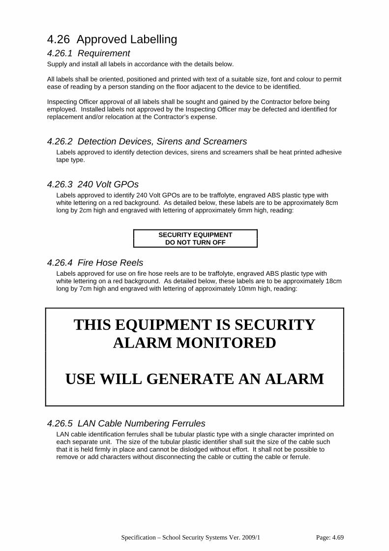
Specification – School Security Systems Ver. 2009/1 Page: 4.69
4.26 Approved Labelling 4.26.1 Requirement Supply and install all labels in accordance with the details below. All labels shall be oriented, positioned and printed with text of a suitable size, font and colour to permit ease of reading by a person standing on the floor adjacent to the device to be identified. Inspecting Officer approval of all labels shall be sought and gained by the Contractor before being employed. Installed labels not approved by the Inspecting Officer may be defected and identified for replacement and/or relocation at the Contractor’s expense.
4.26.2 Detection Devices, Sirens and Screamers Labels approved to identify detection devices, sirens and screamers shall be heat printed adhesive tape type.
4.26.3 240 Volt GPOs Labels approved to identify 240 Volt GPOs are to be traffolyte, engraved ABS plastic type with white lettering on a red background. As detailed below, these labels are to be approximately 8cm long by 2cm high and engraved with lettering of approximately 6mm high, reading:
SECURITY EQUIPMENT DO NOT TURN OFF
4.26.4 Fire Hose Reels Labels approved for use on fire hose reels are to be traffolyte, engraved ABS plastic type with white lettering on a red background. As detailed below, these labels are to be approximately 18cm long by 7cm high and engraved with lettering of approximately 10mm high, reading:
THIS EQUIPMENT IS SECURITY ALARM MONITORED
USE WILL GENERATE AN ALARM
4.26.5 LAN Cable Numbering Ferrules LAN cable identification ferrules shall be tubular plastic type with a single character imprinted on each separate unit. The size of the tubular plastic identifier shall suit the size of the cable such that it is held firmly in place and cannot be dislodged without effort. It shall not be possible to remove or add characters without disconnecting the cable or cutting the cable or ferrule.
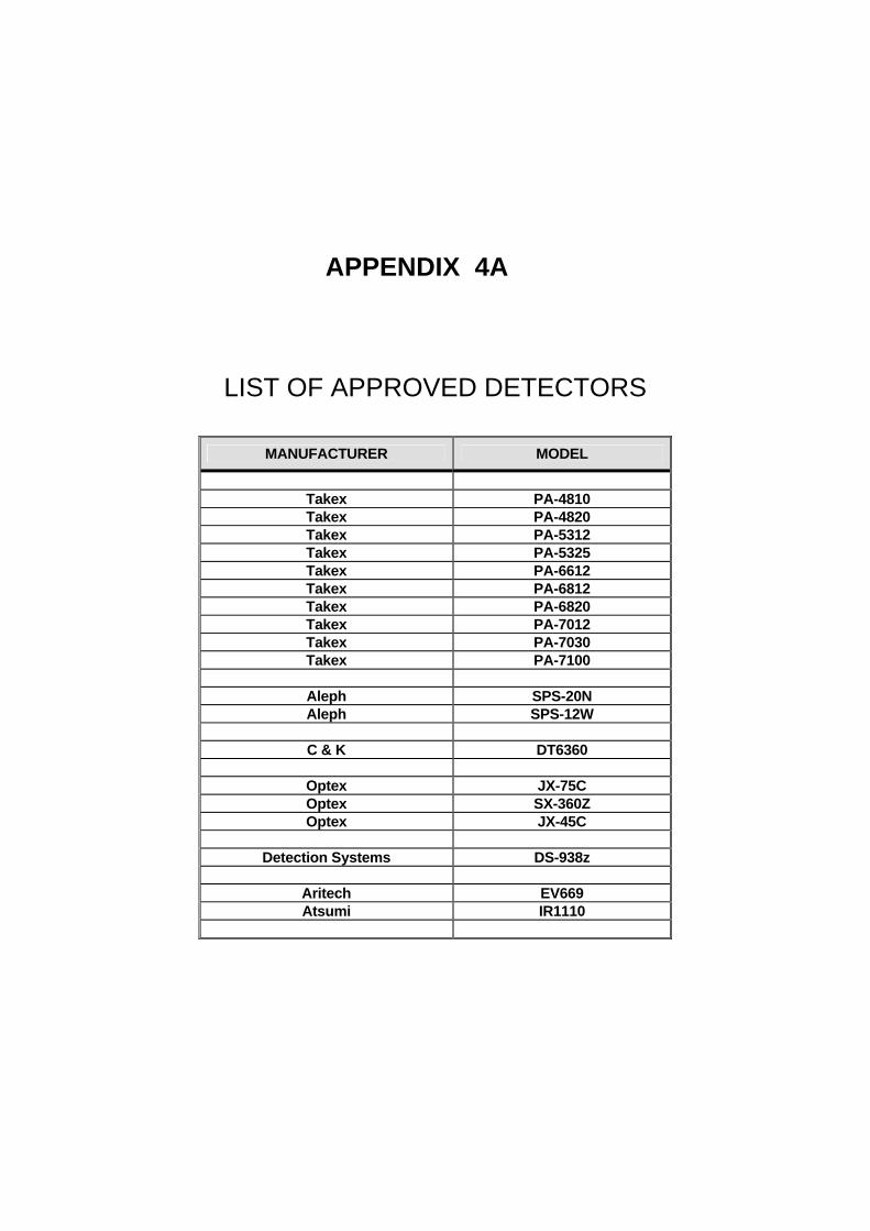
APPENDIX 4A
LIST OF APPROVED DETECTORS
MANUFACTURER MODEL
Takex PA-4810 Takex PA-4820 Takex PA-5312 Takex PA-5325 Takex PA-6612 Takex PA-6812 Takex PA-6820 Takex PA-7012 Takex PA-7030 Takex PA-7100
Aleph SPS-20N Aleph SPS-12W
C & K DT6360
Optex JX-75C Optex SX-360Z Optex JX-45C
Detection Systems DS-938z
Aritech EV669 Atsumi IR1110
APPENDIX 4B
CLAUSE 4.15 COMPLIANCE EXAMPLES
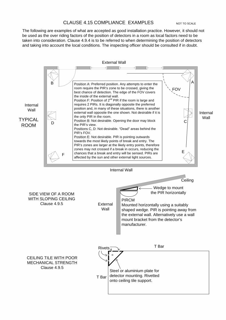
B A
D
FOV
C
FE
Position A: Preferred position. Any attempts to enter the room require the PIR’s zone to be crossed, giving the best chance of detection. The edge of the FOV covers the inside of the external wall.Position F: Position of 2nd PIR if the room is large and requires 2 PIRs. It is diagonally opposite the preferred position and, in many of these situations, there is another external wall opposite the one shown. Not desirable if it is the only PIR in the room.Position B: Not desirable. Opening the door may block the PIR’s view.Positions C, D: Not desirable. “Dead” areas behind the PIR’s FOV.Position E: Not desirable. PIR is pointing outwards towards the most likely points of break and entry. The PIR’s zones are larger at the likely entry points, therefore zones may not crossed if a break in occurs, reducing the chances that a break and entry will be sensed. PIRs are affected by the sun and other external light sources.
External Wall
Internal Wall
Internal Wall
InternalWall
PIRCMMounted horizontally using a suitably shaped wedge. PIR is pointing away from the external wall. Alternatively use a wall mount bracket from the detector’s manufacturer.
Wedge to mount the PIR horizontally
External Wall
Ceiling
Rivets
Steel or aluminium plate for detector mounting. Rivetted onto ceiling tile support.
TYPICAL ROOM
SIDE VIEW OF A ROOM WITH SLOPING CEILING
Clause 4.9.5
CEILING TILE WITH POOR MECHANICAL STRENGTH
Clause 4.9.5
CLAUSE 4.15 COMPLIANCE EXAMPLES NOT TO SCALE
T Bar
T Bar
The following are examples of what are accepted as good installation practice. However, it should not be used as the over riding factors of the position of detectors in a room as local factors need to be taken into consideration. Clause 4.9.4 is to be referred to when determining the position of detectors and taking into account the local conditions. The inspecting officer should be consulted if in doubt.
APPENDIX 4C
FIRE HOSE REEL WATER FLOW SWITCH DETAIL
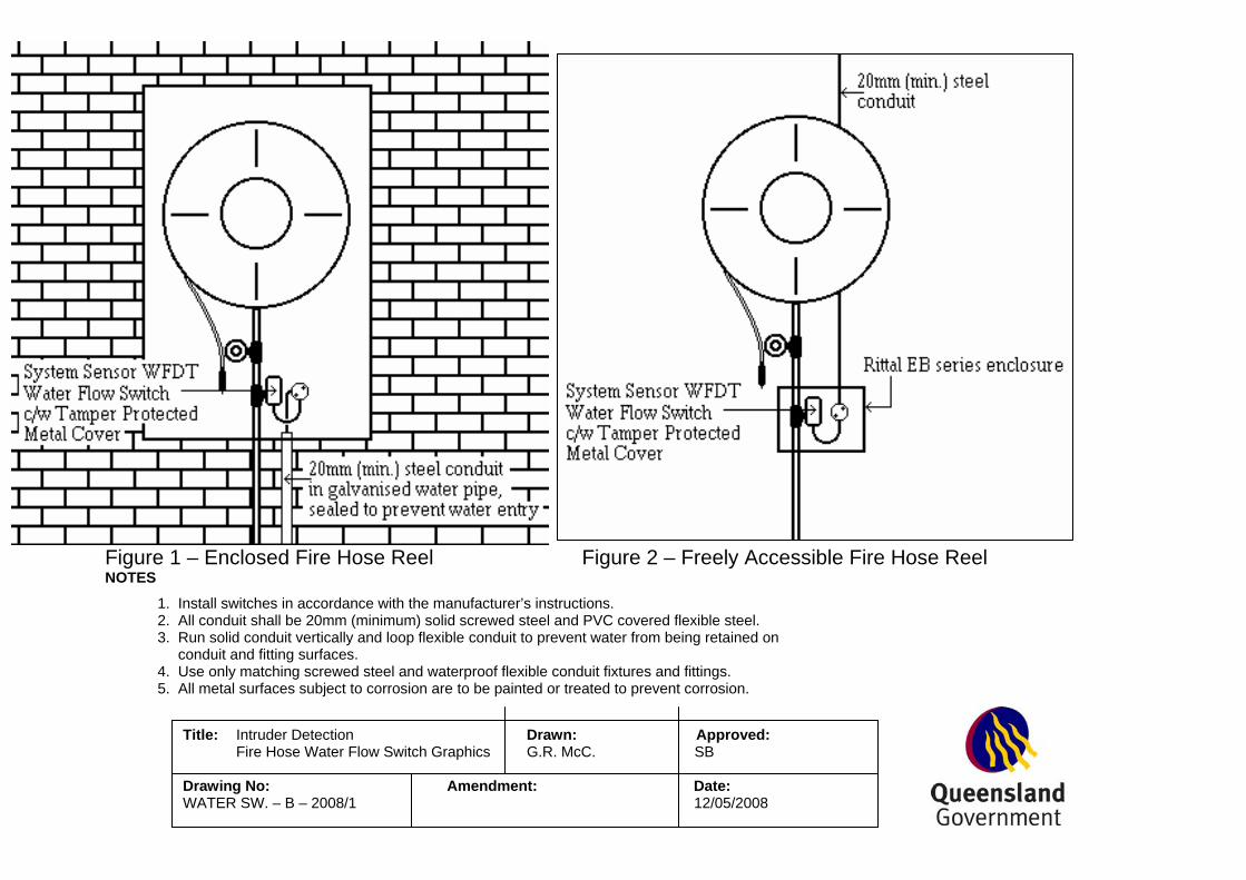
Figure 1 – Enclosed Fire Hose Reel Figure 2 – Freely Accessible Fire Hose Reel NOTES
1. Install switches in accordance with the manufacturer’s instructions. 2. All conduit shall be 20mm (minimum) solid screwed steel and PVC covered flexible steel. 3. Run solid conduit vertically and loop flexible conduit to prevent water from being retained on conduit and fitting surfaces. 4. Use only matching screwed steel and waterproof flexible conduit fixtures and fittings. 5. All metal surfaces subject to corrosion are to be painted or treated to prevent corrosion.
Title: Intruder Detection Drawn: Approved: Fire Hose Water Flow Switch Graphics G.R. McC. SB Drawing No: Amendment: Date: WATER SW. – B – 2008/1 12/05/2008