schaltverstärker typ ksr-opto.250x.xx transducer type ksr ... · ksr kuebler niveau-messtechnik...
TRANSCRIPT

Opto Electronic Level Switch Schaltverstärker Typ KSR-OPTO.250X.XX Transducer Type KSR-OPTO.X1X300XXX.06XX Transducer Type KSR-OPTO.0032 Transducer Type KSR-OPTO.0042 INSTRUCTION MANUAL
RE
V. 1
5.0
4.2
019

KSR KUEBLER Niveau-Messtechnik GmbH, Heinrich-Kuebler-Platz 1, 69439 Zwingenberg am Neckar, Telefon: 0 62 63/87-0, Telefax: 0 62 63/87-99
2
_________________________________________________________________
KSR KUEBLER Niveau-Messtechnik GmbH Heinrich-Kuebler-Platz 1 69439 Zwingenberg am Neckar Phone: 0 62 63/87-0 Fax: 0 62 63/87-99 E-Mail: [email protected] Internet: www.ksr-kuebler.com
KSR KUEBLER Niveau-Messtechnik GmbH, Heinrich-Kuebler-Platz 1, 69439 Zwingenberg am Neckar, Telefon: 0 62 63/87-0, Telefax: 0 62 63/87-99
3
CONTENT
Seite
1. WORKING PRINCIPLE 6
1.1 Used symbols 6
1.2 Quality 7
1.3 RANGE OF APPLICATION 8
1.4 Range of Application, Selection of products 9
1.5 Installation hints 10 1.5.1 Transducer Type KSR-OPTO.0042, connections for glass apparatus 10 1.5.2 Transducer Type KSR-OPTO.0032 10 1.5.3 Transducer Type Typ KSR-OPTO.X1X300XXX.06XX 11
2. SELECTION TABLE 12
2.1 Multi-part Transducer Type KSR-OPTO.X1X300XXX.06XX 13 2.1.1 Multi-part Transducer Type KSR-OPTO.X1X300XXX.0660 13 2.1.2 Multi-part Transducer Type KSR-OPTO.X1X300XXX.0680 13 2.1.3 Multi-part Transducer Type KSR-OPTO.X1X300XXX.0689 13 2.1.4 Multi-part Transducer Type KSR-OPTO.X1X300XXX.06XX 14 2.1.5 Construction details of Level and Interface sensors 14
2.2 One-piece Transducer Type KSR-OPTO.....0032 15
2.3 One-piece Transducer Type KSR-OPTO.....0042, completely made of glass 15
2.4 Amplifier 19” type KSR-OPTO.250X.X7 16
2.5 Amplifier in a damp-proofed housing type KSR-OPTO.250X.X1 18
3. PUTTING INTO OPERATION 19 Checking the completeness of the shipment 19 Intermediate Storage 19 Safety note operating conditions 19
3.1 Mechanical assembly of the transducer 19 Safety note pressure balance 19 Ex hint 'Use Directive' 20 Ex hint for operating type KSR-OPTO.21X300XXX.06XX in zone 0 20 Ex hint ambient temperature 20
Ex hint to the operating conditions for service with flammable measuring mixtures – which are non-explosive – and higher pressures 20
Safety note installation 20 Safety note assembly 20 3.1.1 Pressure and leage test 20
3.2 Mechanische Montage des Schaltverstärkers 21
3.3 Electrical connection transducer and amplifier 21 Safety note electrical installation 21 3.3.1 Connection diagram transducer and amplifier 22 Safety note electrical installation 22
KSR KUEBLER Niveau-Messtechnik GmbH, Heinrich-Kuebler-Platz 1, 69439 Zwingenberg am Neckar, Telefon: 0 62 63/87-0, Telefax: 0 62 63/87-99
4
3.3.2 Electrical Connection Transducer 23 Earthing type KSR-OPTO.21X300XXX.06XX 23 3.3.3 Elektrischer Anschluss Schaltverstärker 23
3.4 Connection supply 24
3.5 Connection relays 24
3.6 Function control 24
4. OPERATION 25
4.1 Setting of fail-safe direction with switch S1 25
4.2 Calibration with CAL 26
4.3 Justage of time delay 27
4.4 TEST- Procedure 28
4.5 Operating characteristics relay signal 29
4.6 Operating characteristics relay failure 29
5. MAINTENANCE 29
6. GUARANTEE 29
7. RETURN-TO-MANUFACTURER 30
8. DISPOSAL 30
9. REPAIR 31
9.1 Repair Transducer 31
9.2 Replacing fuse of amplifier 31 Safety hint replacement fuse 31
9.3 Miscellaneous 31
10. TROUBLE SHOOTING 32
11. TECHNICAL DATA 33
11.1 Transducer 33 11.1.1 One-piece transducer 33 11.1.2 Multipart transducer 34
11.2 Amplifier 35
12. SELECTION CODE 37
12.1 Type KSR-OPTO.0032 one-piece transducer 37
KSR KUEBLER Niveau-Messtechnik GmbH, Heinrich-Kuebler-Platz 1, 69439 Zwingenberg am Neckar, Telefon: 0 62 63/87-0, Telefax: 0 62 63/87-99
5
12.2 Typ KSR-OPTO.0042 aus Glas, einteilige Messwandler 38
12.3 Typ KSR-OPTO.X1X300XXX.06XX mehrteilige Messwandler 39
12.4 Typ KSR-OPTO.250X.XX Schaltverstärker 42
13 SAFETY MANUAL 43
13.1 General 43 13.1.1 Validity 43 13.1.2 Relevant standards 43 13.1.3 Determination of safety-related characteristics 44
13.2 Planning 44 13.2.1 Low demand mode 44 13.2.2 High demand or continuous mode 44 13.2.3 General 44
13.3 Set-up 45 13.3.1 Mounting and installation 45
13.4 Reaction during operation and in case of failure 45
13.5 Recurring function test 45 13.5.1 Safety-related characteristics 46
14. EC-TYPE_EXAMINATION CERTIFICATES 47
14.1 CE 60
KSR KUEBLER Niveau-Messtechnik GmbH, Heinrich-Kuebler-Platz 1, 69439 Zwingenberg am Neckar, Telefon: 0 62 63/87-0, Telefax: 0 62 63/87-99
6
1. WORKING PRINCIPLE
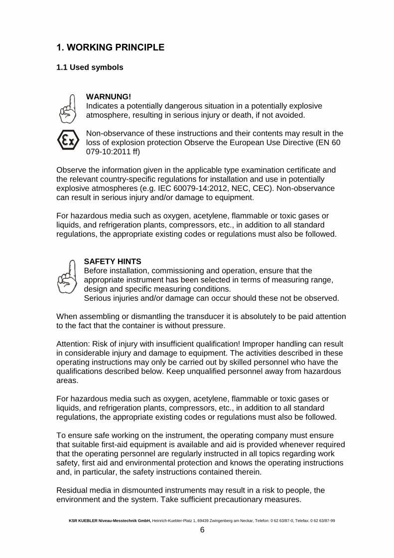
1.1 Used symbols
WARNUNG! Indicates a potentially dangerous situation in a potentially explosive atmosphere, resulting in serious injury or death, if not avoided. Non-observance of these instructions and their contents may result in the loss of explosion protection Observe the European Use Directive (EN 60 079-10:2011 ff)
Observe the information given in the applicable type examination certificate and the relevant country-specific regulations for installation and use in potentially explosive atmospheres (e.g. IEC 60079-14:2012, NEC, CEC). Non-observance can result in serious injury and/or damage to equipment. For hazardous media such as oxygen, acetylene, flammable or toxic gases or liquids, and refrigeration plants, compressors, etc., in addition to all standard regulations, the appropriate existing codes or regulations must also be followed.
SAFETY HINTS Before installation, commissioning and operation, ensure that the appropriate instrument has been selected in terms of measuring range, design and specific measuring conditions. Serious injuries and/or damage can occur should these not be observed.
When assembling or dismantling the transducer it is absolutely to be paid attention to the fact that the container is without pressure. Attention: Risk of injury with insufficient qualification! Improper handling can result in considerable injury and damage to equipment. The activities described in these operating instructions may only be carried out by skilled personnel who have the qualifications described below. Keep unqualified personnel away from hazardous areas. For hazardous media such as oxygen, acetylene, flammable or toxic gases or liquids, and refrigeration plants, compressors, etc., in addition to all standard regulations, the appropriate existing codes or regulations must also be followed. To ensure safe working on the instrument, the operating company must ensure that suitable first-aid equipment is available and aid is provided whenever required that the operating personnel are regularly instructed in all topics regarding work safety, first aid and environmental protection and knows the operating instructions and, in particular, the safety instructions contained therein. Residual media in dismounted instruments may result in a risk to people, the environment and the system. Take sufficient precautionary measures.
KSR KUEBLER Niveau-Messtechnik GmbH, Heinrich-Kuebler-Platz 1, 69439 Zwingenberg am Neckar, Telefon: 0 62 63/87-0, Telefax: 0 62 63/87-99
7
Do not use this instrument in safety or Emergency Stop devices. Incorrect use of the instrument can result in injury. Should a failure occur, aggressive media with extremely high temperature and under high pressure or vacuum may be present at the instrument. WARNING!
Danger of death caused by electric current Upon contact with live parts, there is a direct danger of death. Electrical instruments may only be installed and mounted by skilled
electrical personnel. Operation using a defective power supply unit (e.g. short circuit from the mains voltage to the output voltage) may result in life-threatening voltages on the instrument!
1.2 Quality
All devices are produced within an approved QM-System under DIN EN ISO 9001.
KSR KUEBLER Niveau-Messtechnik GmbH, Heinrich-Kuebler-Platz 1, 69439 Zwingenberg am Neckar, Telefon: 0 62 63/87-0, Telefax: 0 62 63/87-99
8
1.3 RANGE OF APPLICATION
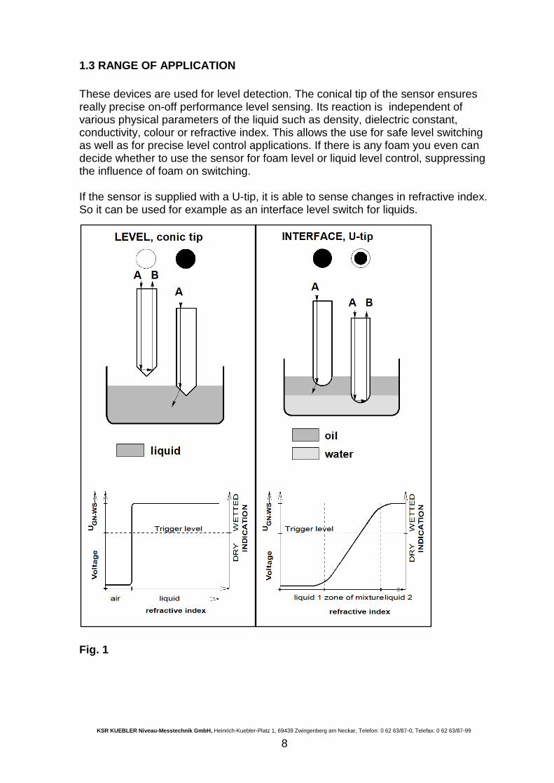
These devices are used for level detection. The conical tip of the sensor ensures really precise on-off performance level sensing. Its reaction is independent of various physical parameters of the liquid such as density, dielectric constant, conductivity, colour or refractive index. This allows the use for safe level switching as well as for precise level control applications. If there is any foam you even can decide whether to use the sensor for foam level or liquid level control, suppressing the influence of foam on switching. If the sensor is supplied with a U-tip, it is able to sense changes in refractive index. So it can be used for example as an interface level switch for liquids.
Fig. 1
KSR KUEBLER Niveau-Messtechnik GmbH, Heinrich-Kuebler-Platz 1, 69439 Zwingenberg am Neckar, Telefon: 0 62 63/87-0, Telefax: 0 62 63/87-99
9
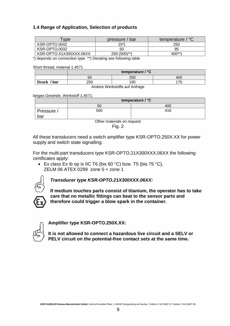
1.4 Range of Application, Selection of products
Type pressure / bar temperature / °C KSR-OPTO.0042 10*) 250
KSR-OPTO.0032 50 95
KSR-OPTO.X1X300XXX.06XX 250 (500)**) 400**)
*) depends on connection type **) Derating see following table Short thread, material 1.4571
temperature / °C
50 250 400
Druck / bar 250 195 175
Andere Werkstoffe auf Anfrage langes Gewinde, Werkstoff 1.4571:
temperature / °C
50 400
Pressure / bar
500 416
Other materials on request Fig. 2
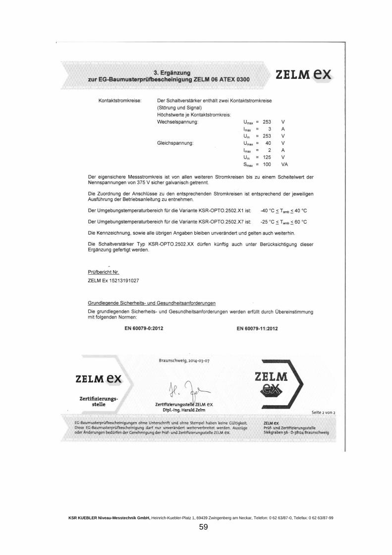
All these transducers need a switch amplifier type KSR-OPTO.250X.XX for power supply and switch state signalling. For the multi-part transducers type KSR-OPTO.21X300XXX.06XX the following certificates apply:
Ex class Ex ib op is IIC T6 (bis 60 °C) bzw. T5 (bis 75 °C), ZELM 06 ATEX 0299 zone 0 + zone 1
Transducer type KSR-OPTO.21X300XXX.06XX: If medium touches parts consist of titanium, the operator has to take care that no metallic fittings can beat to the sensor parts and therefore could trigger a blow spark in the container.
Amplifier type KSR-OPTO.250X.XX: It is not allowed to connect a hazardous live circuit and a SELV or PELV circuit on the potential-free contact sets at the same time.
KSR KUEBLER Niveau-Messtechnik GmbH, Heinrich-Kuebler-Platz 1, 69439 Zwingenberg am Neckar, Telefon: 0 62 63/87-0, Telefax: 0 62 63/87-99
10
1.5 Installation hints
The sensors may be installed in any direction, i. e. from top, bottom, sideways or inclined. In some special applications it is recommended to use following hints:
High viscosity: sideways or from bottom
Dry Running protection for pumps: If the pipes to or from the pump are installed horizontally use top mounting for fast detection of liquid
Overfill prevention devices: Usually vertically from above
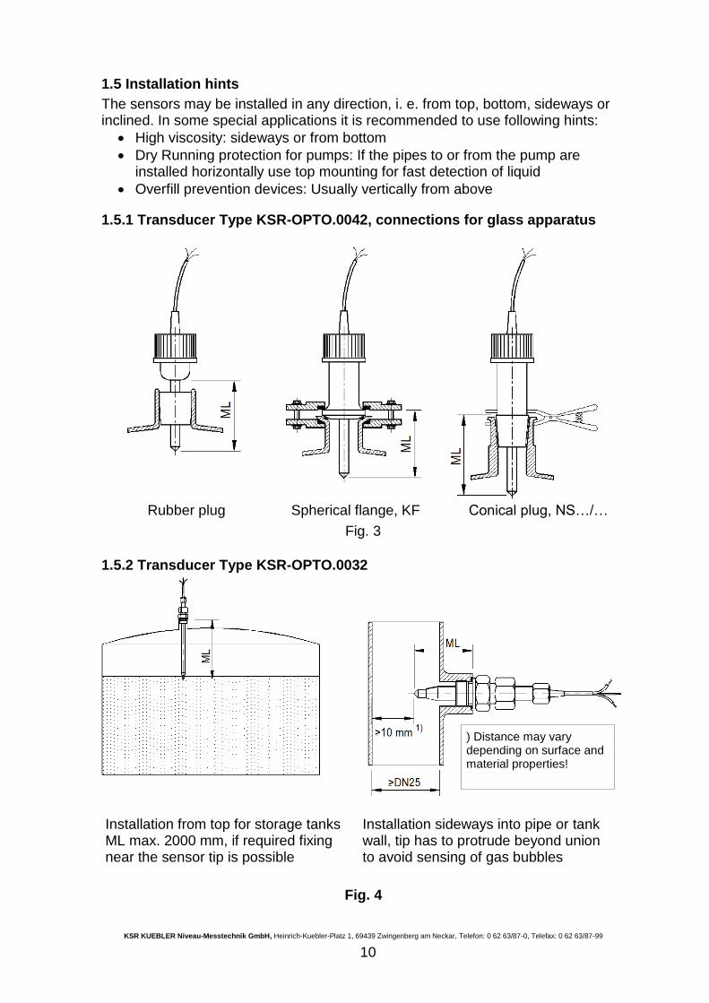
1.5.1 Transducer Type KSR-OPTO.0042, connections for glass apparatus
Rubber plug Spherical flange, KF Conical plug, NS…/…
Fig. 3
1.5.2 Transducer Type KSR-OPTO.0032
Installation from top for storage tanks ML max. 2000 mm, if required fixing near the sensor tip is possible
Installation sideways into pipe or tank wall, tip has to protrude beyond union to avoid sensing of gas bubbles
Fig. 4
) Distance may vary depending on surface and material properties!
KSR KUEBLER Niveau-Messtechnik GmbH, Heinrich-Kuebler-Platz 1, 69439 Zwingenberg am Neckar, Telefon: 0 62 63/87-0, Telefax: 0 62 63/87-99
11
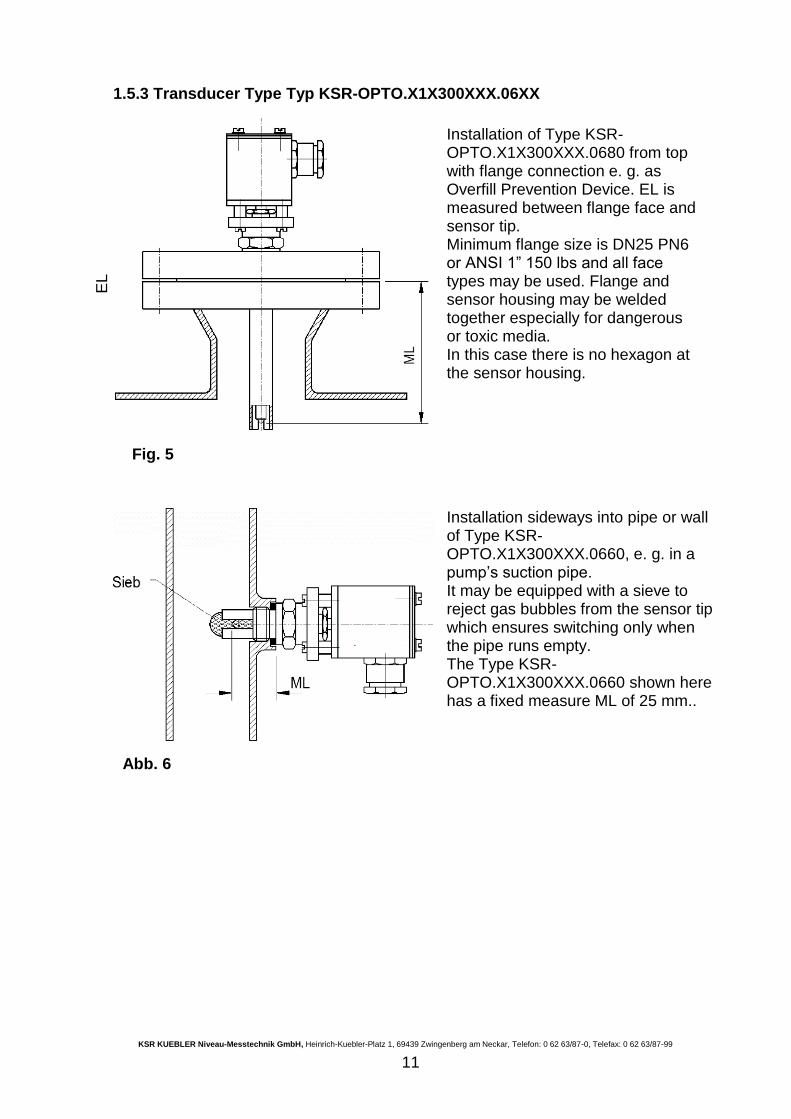
1.5.3 Transducer Type Typ KSR-OPTO.X1X300XXX.06XX
Installation of Type KSR-OPTO.X1X300XXX.0680 from top with flange connection e. g. as Overfill Prevention Device. EL is measured between flange face and sensor tip. Minimum flange size is DN25 PN6 or ANSI 1” 150 lbs and all face types may be used. Flange and sensor housing may be welded together especially for dangerous or toxic media. In this case there is no hexagon at the sensor housing.
Fig. 5
Installation sideways into pipe or wall of Type KSR-OPTO.X1X300XXX.0660, e. g. in a pump’s suction pipe. It may be equipped with a sieve to reject gas bubbles from the sensor tip which ensures switching only when the pipe runs empty. The Type KSR-OPTO.X1X300XXX.0660 shown here has a fixed measure ML of 25 mm..
Abb. 6
EL
KSR KUEBLER Niveau-Messtechnik GmbH, Heinrich-Kuebler-Platz 1, 69439 Zwingenberg am Neckar, Telefon: 0 62 63/87-0, Telefax: 0 62 63/87-99
12
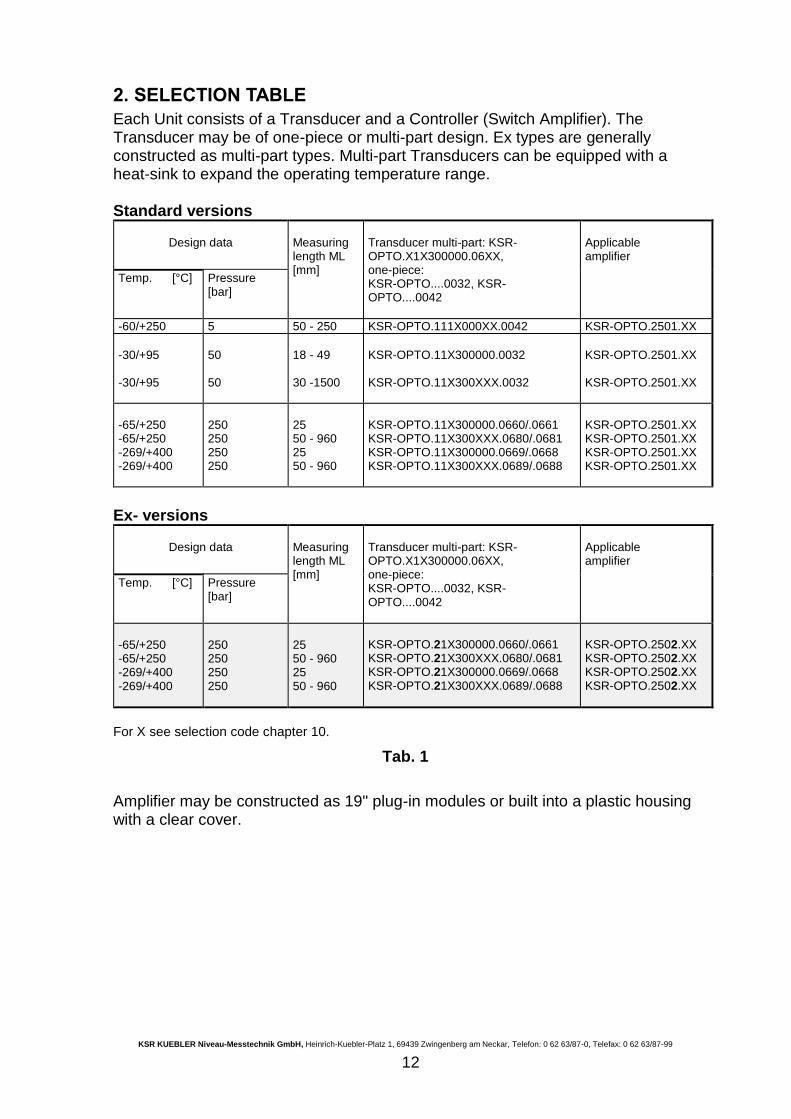
2. SELECTION TABLE
Each Unit consists of a Transducer and a Controller (Switch Amplifier). The Transducer may be of one-piece or multi-part design. Ex types are generally constructed as multi-part types. Multi-part Transducers can be equipped with a heat-sink to expand the operating temperature range. Standard versions
Design data Measuring length ML [mm]
Transducer multi-part: KSR-OPTO.X1X300000.06XX, one-piece: KSR-OPTO....0032, KSR-OPTO....0042
Applicable amplifier
Temp. [°C] Pressure [bar]
-60/+250 5 50 - 250 KSR-OPTO.111X000XX.0042 KSR-OPTO.2501.XX
-30/+95 -30/+95
50 50
18 - 49 30 -1500
KSR-OPTO.11X300000.0032 KSR-OPTO.11X300XXX.0032
KSR-OPTO.2501.XX KSR-OPTO.2501.XX
-65/+250 -65/+250 -269/+400 -269/+400
250 250 250 250
25 50 - 960 25 50 - 960
KSR-OPTO.11X300000.0660/.0661 KSR-OPTO.11X300XXX.0680/.0681 KSR-OPTO.11X300000.0669/.0668 KSR-OPTO.11X300XXX.0689/.0688
KSR-OPTO.2501.XX KSR-OPTO.2501.XX KSR-OPTO.2501.XX KSR-OPTO.2501.XX
Ex- versions
Design data Measuring length ML [mm]
Transducer multi-part: KSR-OPTO.X1X300000.06XX, one-piece: KSR-OPTO....0032, KSR-OPTO....0042
Applicable amplifier
Temp. [°C] Pressure [bar]
-65/+250 -65/+250 -269/+400 -269/+400
250 250 250 250
25 50 - 960 25 50 - 960
KSR-OPTO.21X300000.0660/.0661 KSR-OPTO.21X300XXX.0680/.0681 KSR-OPTO.21X300000.0669/.0668 KSR-OPTO.21X300XXX.0689/.0688
KSR-OPTO.2502.XX KSR-OPTO.2502.XX KSR-OPTO.2502.XX KSR-OPTO.2502.XX
For X see selection code chapter 10.
Tab. 1
Amplifier may be constructed as 19" plug-in modules or built into a plastic housing with a clear cover.
KSR KUEBLER Niveau-Messtechnik GmbH, Heinrich-Kuebler-Platz 1, 69439 Zwingenberg am Neckar, Telefon: 0 62 63/87-0, Telefax: 0 62 63/87-99
13
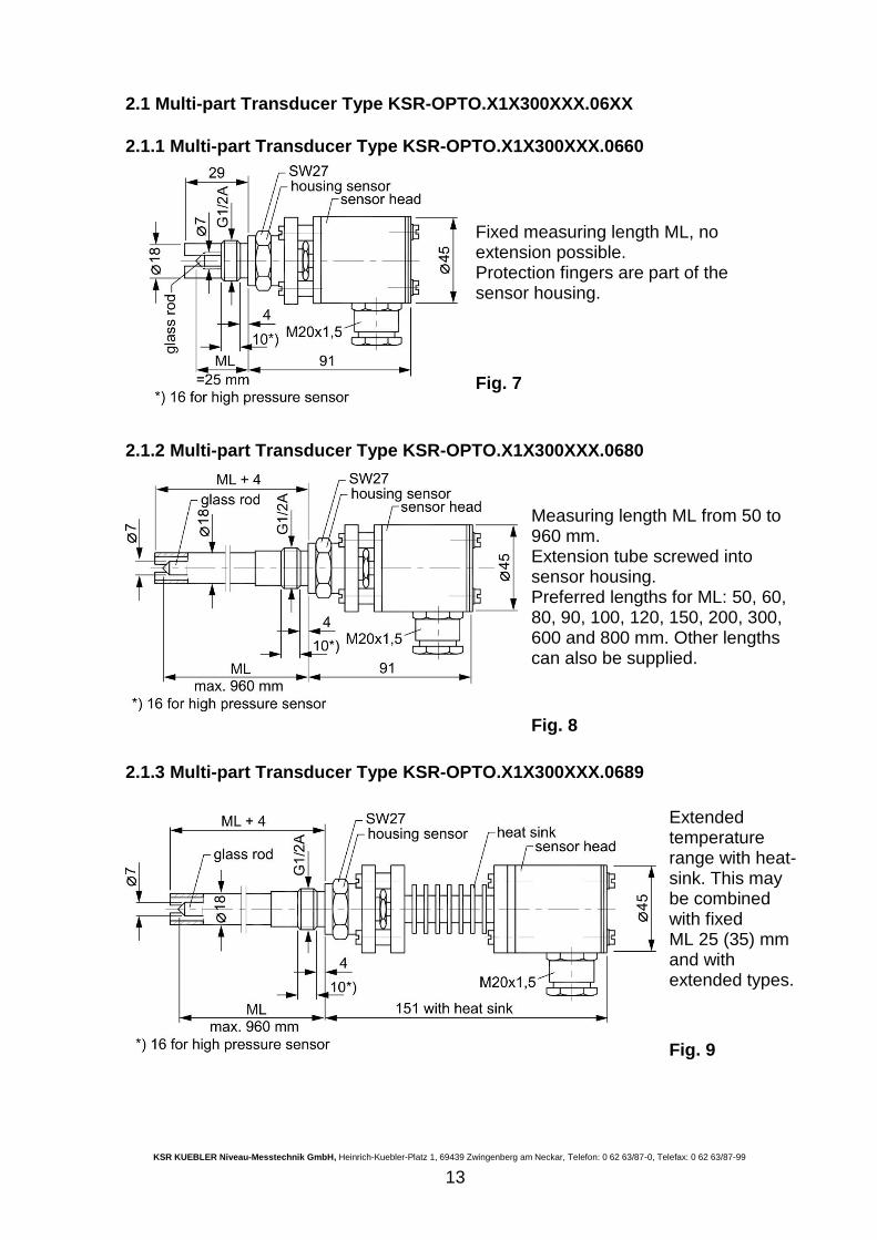
2.1 Multi-part Transducer Type KSR-OPTO.X1X300XXX.06XX
2.1.1 Multi-part Transducer Type KSR-OPTO.X1X300XXX.0660
Fixed measuring length ML, no extension possible. Protection fingers are part of the sensor housing.
Fig. 7
2.1.2 Multi-part Transducer Type KSR-OPTO.X1X300XXX.0680
Measuring length ML from 50 to 960 mm. Extension tube screwed into sensor housing. Preferred lengths for ML: 50, 60, 80, 90, 100, 120, 150, 200, 300, 600 and 800 mm. Other lengths can also be supplied.
Fig. 8
2.1.3 Multi-part Transducer Type KSR-OPTO.X1X300XXX.0689
Extended temperature range with heat-sink. This may be combined with fixed ML 25 (35) mm and with extended types.
Fig. 9
KSR KUEBLER Niveau-Messtechnik GmbH, Heinrich-Kuebler-Platz 1, 69439 Zwingenberg am Neckar, Telefon: 0 62 63/87-0, Telefax: 0 62 63/87-99
14
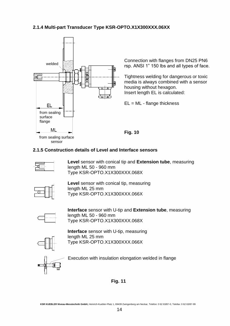
2.1.4 Multi-part Transducer Type KSR-OPTO.X1X300XXX.06XX
Connection with flanges from DN25 PN6 rsp. ANSI 1” 150 lbs and all types of face. Tightness welding for dangerous or toxic media is always combined with a sensor housing without hexagon. Insert length EL is calculated: EL = ML - flange thickness
Fig. 10
2.1.5 Construction details of Level and Interface sensors
Level sensor with conical tip and Extension tube, measuring length ML 50 - 960 mm Type KSR-OPTO.X1X300XXX.068X Level sensor with conical tip, measuring length ML 25 mm Type KSR-OPTO.X1X300XXX.066X Interface sensor with U-tip and Extension tube, measuring length ML 50 - 960 mm Type KSR-OPTO.X1X300XXX.068X Interface sensor with U-tip, measuring length ML 25 mm Type KSR-OPTO.X1X300XXX.066X Execution with insulation elongation welded in flange
Fig. 11
welded
from sealing surface flange
from sealing surface sensor
KSR KUEBLER Niveau-Messtechnik GmbH, Heinrich-Kuebler-Platz 1, 69439 Zwingenberg am Neckar, Telefon: 0 62 63/87-0, Telefax: 0 62 63/87-99
15
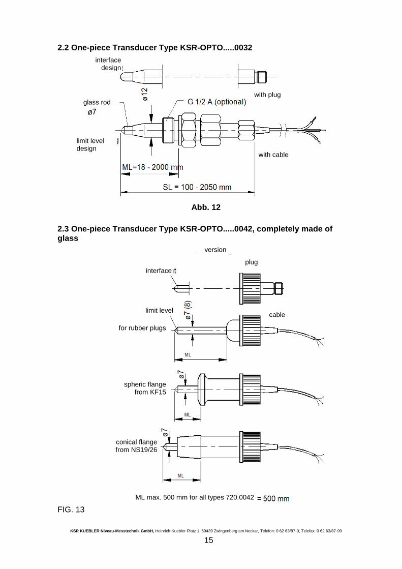
2.2 One-piece Transducer Type KSR-OPTO.....0032
Abb. 12
2.3 One-piece Transducer Type KSR-OPTO.....0042, completely made of glass
FIG. 13
interface design
with plug glass rod
with cable
limit level design
version
interface
limit level
plug
cable
for rubber plugs
spheric flange from KF15
conical flange from NS19/26
ML max. 500 mm for all types 720.0042
KSR KUEBLER Niveau-Messtechnik GmbH, Heinrich-Kuebler-Platz 1, 69439 Zwingenberg am Neckar, Telefon: 0 62 63/87-0, Telefax: 0 62 63/87-99
16
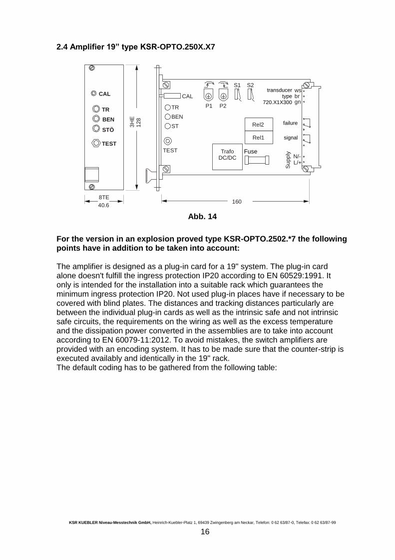
2.4 Amplifier 19” type KSR-OPTO.250X.X7
S1wsbrgn
CAL
BEN
STÖ
TEST
TR
TEST
ST
CAL
BEN
TR
TrafoDC/DC
P2
S2
P1
Rel1
Rel2
N/-L/+
Su
pp
ly
3H
E1
28
8TE
40.6160
Abb. 14
For the version in an explosion proved type KSR-OPTO.2502.*7 the following points have in addition to be taken into account: The amplifier is designed as a plug-in card for a 19" system. The plug-in card alone doesn't fulfill the ingress protection IP20 according to EN 60529:1991. It only is intended for the installation into a suitable rack which guarantees the minimum ingress protection IP20. Not used plug-in places have if necessary to be covered with blind plates. The distances and tracking distances particularly are between the individual plug-in cards as well as the intrinsic safe and not intrinsic safe circuits, the requirements on the wiring as well as the excess temperature and the dissipation power converted in the assemblies are to take into account according to EN 60079-11:2012. To avoid mistakes, the switch amplifiers are provided with an encoding system. It has to be made sure that the counter-strip is executed availably and identically in the 19" rack. The default coding has to be gathered from the following table:
Fuse
transducer type
720.X1X300XXX.06XX
failure
signal
KSR KUEBLER Niveau-Messtechnik GmbH, Heinrich-Kuebler-Platz 1, 69439 Zwingenberg am Neckar, Telefon: 0 62 63/87-0, Telefax: 0 62 63/87-99
17
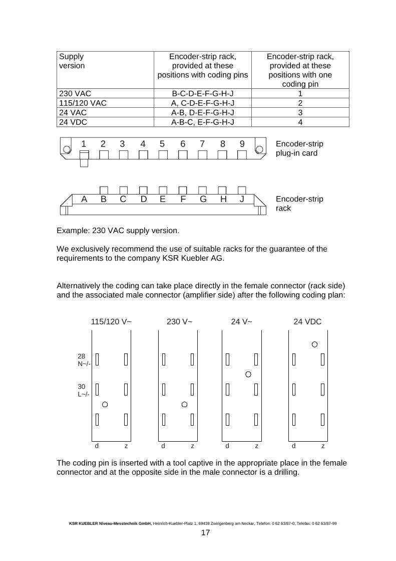
Supply version
Encoder-strip rack, provided at these
positions with coding pins
Encoder-strip rack, provided at these positions with one
coding pin
230 VAC B-C-D-E-F-G-H-J 1
115/120 VAC A, C-D-E-F-G-H-J 2
24 VAC A-B, D-E-F-G-H-J 3
24 VDC A-B-C, E-F-G-H-J 4
A
1
C
3
B
2
D
4
E
5
F
6
G
7
H
8
J
9
Example: 230 VAC supply version. We exclusively recommend the use of suitable racks for the guarantee of the requirements to the company KSR Kuebler AG. Alternatively the coding can take place directly in the female connector (rack side) and the associated male connector (amplifier side) after the following coding plan:
115/120 V~
28N~/-
30L~/-
d z d z d zd z
230 V~ 24 V~ 24 VDC
The coding pin is inserted with a tool captive in the appropriate place in the female connector and at the opposite side in the male connector is a drilling.
Encoder-strip plug-in card
Encoder-strip rack
KSR KUEBLER Niveau-Messtechnik GmbH, Heinrich-Kuebler-Platz 1, 69439 Zwingenberg am Neckar, Telefon: 0 62 63/87-0, Telefax: 0 62 63/87-99
18
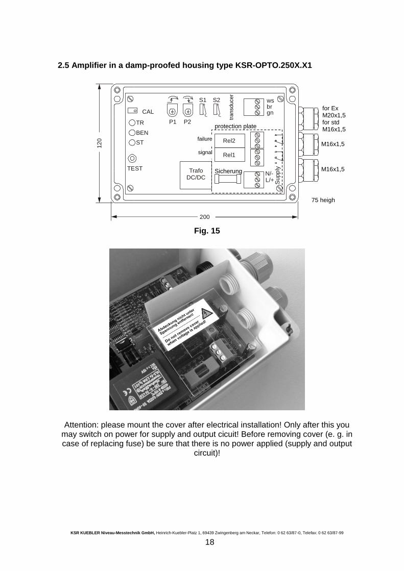
2.5 Amplifier in a damp-proofed housing type KSR-OPTO.250X.X1
S1 wsbrgn
P2
S2
P1
N/-L/+ S
upp
lyTEST
ST
TR
CAL
BEN
TrafoDC/DC
Rel1
Rel2
200
12
0
Fig. 15
Attention: please mount the cover after electrical installation! Only after this you may switch on power for supply and output cicuit! Before removing cover (e. g. in case of replacing fuse) be sure that there is no power applied (supply and output
circuit)!
Sicherung M16x1,5
M16x1,5
75 heigh
failure
signal
for Ex M20x1,5 for std M16x1,5
protection plate
transducer
KSR KUEBLER Niveau-Messtechnik GmbH, Heinrich-Kuebler-Platz 1, 69439 Zwingenberg am Neckar, Telefon: 0 62 63/87-0, Telefax: 0 62 63/87-99
19
3. PUTTING INTO OPERATION
Checking the completeness of the shipment
The completeness of the shipment has to be checked when unpacking. Provided that not agreed particularly, the device travels on the risk of the customer. Possible damages in transit can be immediately asserted under enclosing the documentation according to the legal regulations.
Intermediate Storage
If the assembly doesn't immediately take place after the delivery, the Level Gauge must being stored so much that no negative influences can have an effect. We recommend a dry storage place at temperatures below 0 degrees Celsius without additional other objects stacked on this. Furthermore a check of the function can be carried out before the installation. The device attached provisionally and the glass tip are one and from dived to this for the test in a glass with liquid (justify if necessary in accordance with 4.2). The electrical connection only may be carried out by authorized specialist staff. The appropriate VDE regulations have to be taken into account.
Safety note operating conditions
Before further steps the customer has to check whether furthermore the operating conditions agreed on at the order are valid and the device is suitable for the scheduled purpose. This particularly applies to the features
pressure, temperature and medium.
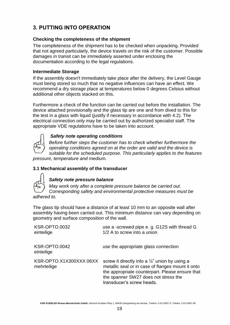
3.1 Mechanical assembly of the transducer
Safety note pressure balance
May work only after a complete pressure balance be carried out. Corresponding safety and environmental protective measures must be
adhered to. The glass tip should have a distance of at least 10 mm to an opposite wall after assembly having been carried out. This minimum distance can vary depending on geometry and surface composition of the wall.
KSR-OPTO.0032 einteilige
use a -screwed pipe e. g. G12S with thread G 1/2 A to screw into a union
KSR-OPTO.0042 einteilige
use the appropriate glass connection
KSR-OPTO.X1X300XXX.06XX mehrteilige
screw it directly into a ½” union by using a metallic seal or in case of flanges mount it onto the appropriate counterpart. Please ensure that the spanner SW27 does not stress the transducer’s screw heads.
KSR KUEBLER Niveau-Messtechnik GmbH, Heinrich-Kuebler-Platz 1, 69439 Zwingenberg am Neckar, Telefon: 0 62 63/87-0, Telefax: 0 62 63/87-99
20
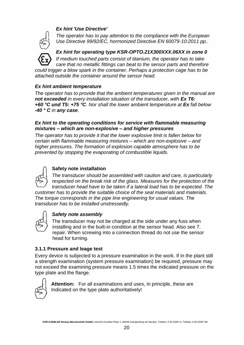
Ex hint 'Use Directive'
The operator has to pay attention to the compliance with the European Use Directive 99/92/EC, hormonized Directive EN 60079-10:2011 pp..
Ex hint for operating type KSR-OPTO.21X300XXX.06XX in zone 0
If medium touched parts consist of titanium, the operator has to take care that no metallic fittings can beat to the sensor parts and therefore
could trigger a blow spark in the container. Perhaps a protection cage has to be attached outside the container around the sensor head.
Ex hint ambient temperature
The operator has to provide that the ambient temperatures given in the manual are not exceeded in every installation situation of the transducer, with Ex T6: +60 °C und T5: +75 °C. Nor shall the lower ambient temperature at Ex fall below -40 ° C in any case.
Ex hint to the operating conditions for service with flammable measuring mixtures – which are non-explosive – and higher pressures
The operator has to provide it that the lower explosive limit is fallen below for certain with flammable measuring mixtures – which are non-explosive – and higher pressures. The formation of explosion capable atmosphere has to be prevented by stopping the evaporating of combustible liquids.
Safety note installation
The transducer should be assembled with caution and care, is particularly respected on the break risk of the glass. Measures for the protection of the transducer head have to be taken if a lateral load has to be expected. The
customer has to provide the suitable choice of the seal materials and materials. The torque corresponds in the pipe line engineering for usual values. The transducer has to be installed unstressedly.
Safety note assembly
The transducer may not be charged at the side under any fuss when installing and in the built-in condition at the sensor head. Also see 7. repair. When screwing into a connection thread do not use the sensor head for turning.
3.1.1 Pressure and leage test
Every device is subjected to a pressure examination in the work. If in the plant still a strength examination (system pressure examination) be required, pressure may not exceed the examining pressure means 1.5 times the indicated pressure on the type plate and the flange.
Attention: For all examinations and uses, in principle, these are Indicated on the type plate authoritatively!
KSR KUEBLER Niveau-Messtechnik GmbH, Heinrich-Kuebler-Platz 1, 69439 Zwingenberg am Neckar, Telefon: 0 62 63/87-0, Telefax: 0 62 63/87-99
21
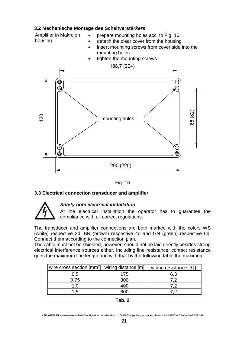
3.2 Mechanische Montage des Schaltverstärkers
Amplifier in Makrolon housing
prepare mounting holes acc. to Fig. 16
detach the clear cover from the housing
insert mounting screws from cover side into the mounting holes
tighten the mounting screws
Fig. 16
3.3 Electrical connection transducer and amplifier
Safety note electrical installation
At the electrical installation the operator has to guarantee the compliance with all correct regulations.
The transducer and amplifier connections are both marked with the colors WS (white) respective 2d, BR (brown) respective 4d and GN (green) respective 6d. Connect them according to the connection plan. The cable must not be shielded, however, should not be laid directly besides strong electrical interference sources either. Including line resistance, contact resistance goes the maximum line length and with that by the following table the maximum:
wire cross section [mm2] wiring distance [m] wiring resistance []
0,5 175 6,3
0,75 300 7,2
1,0 400 7,2
1,5 600 7,2
Tab. 2
mounting holes
KSR KUEBLER Niveau-Messtechnik GmbH, Heinrich-Kuebler-Platz 1, 69439 Zwingenberg am Neckar, Telefon: 0 62 63/87-0, Telefax: 0 62 63/87-99
22
A complete resistance of 9 , inclusive of contact resistances, should not be exceeded since otherwise a failure signal is carried out. A max. inductance of
La 0,5 mH and a max. capacity all over are in addition at of keep Ca 3 F for (incl. the values of the switch amplifier).
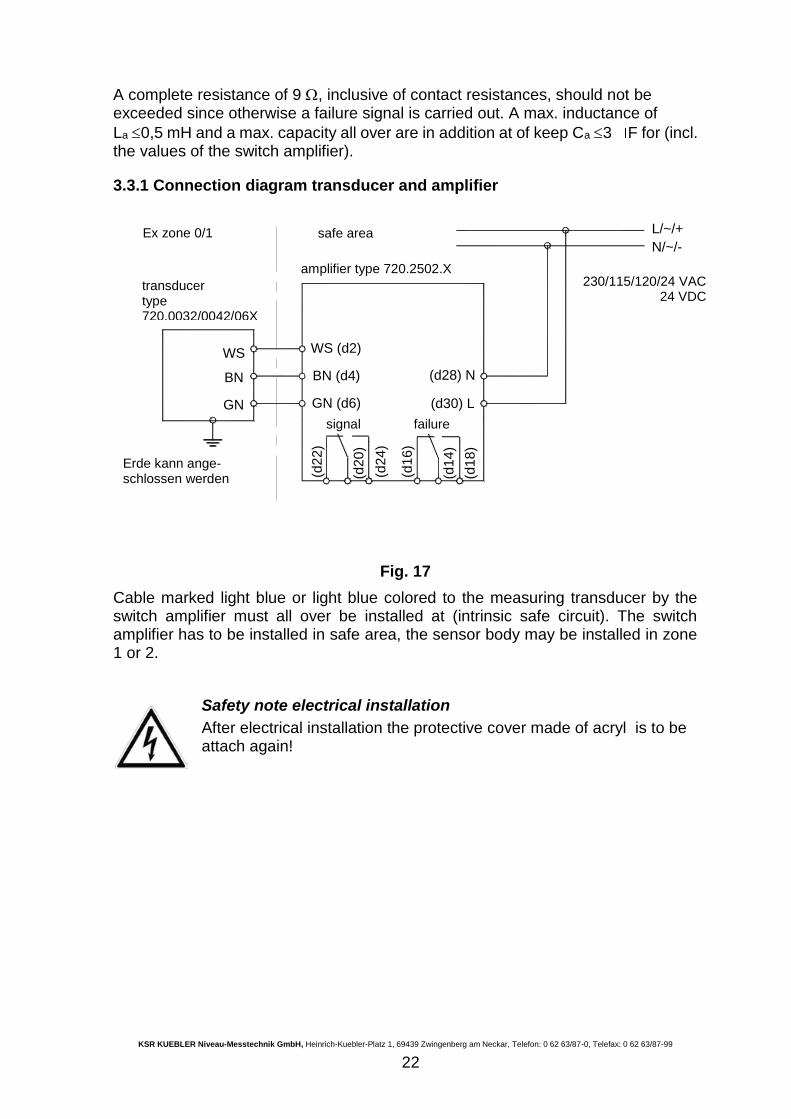
3.3.1 Connection diagram transducer and amplifier
WS
GN
BN
(d2
2)
(d2
4)
(d2
0)
GN (d6)
BN (d4)
WS (d2)
L/~/+
(d1
4)
(d1
6)
(d1
8)
(d28) N
(d30) L
N/~/-
Fig. 17
Cable marked light blue or light blue colored to the measuring transducer by the switch amplifier must all over be installed at (intrinsic safe circuit). The switch amplifier has to be installed in safe area, the sensor body may be installed in zone 1 or 2.
Safety note electrical installation
After electrical installation the protective cover made of acryl is to be attach again!
Erde kann ange- schlossen werden
230/115/120/24 VAC 24 VDC
Ex zone 0/1 safe area
amplifier type 720.2502.X
transducer type 720.0032/0042/06XX
signal failure
KSR KUEBLER Niveau-Messtechnik GmbH, Heinrich-Kuebler-Platz 1, 69439 Zwingenberg am Neckar, Telefon: 0 62 63/87-0, Telefax: 0 62 63/87-99
23
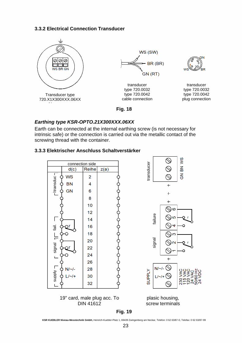
3.3.2 Electrical Connection Transducer
Fig. 18
Earthing type KSR-OPTO.21X300XXX.06XX
Earth can be connected at the internal earthing screw (is not necessary for intrinsic safe) or the connection is carried out via the metallic contact of the screwing thread with the container.
3.3.3 Elektrischer Anschluss Schaltverstärker
19" card, male plug acc. To DIN 41612
plasic housing, screw terminals
Fig. 19
Transducer type 720.X1X300XXX.06XX
transducer type 720.0032 type 720.0042
cable connection
transducer type 720.0032 type 720.0042
plug connection
connection side
transduc
fail.
sig
na
l supply
sig
na
l fa
ilure
transducer
KSR KUEBLER Niveau-Messtechnik GmbH, Heinrich-Kuebler-Platz 1, 69439 Zwingenberg am Neckar, Telefon: 0 62 63/87-0, Telefax: 0 62 63/87-99
24
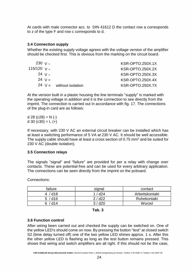
At cards with male connector acc. to DIN 41612 D the contact row a corresponds to z of the type F and row c corresponds to d.
3.4 Connection supply
Whether the existing supply voltage agrees with the voltage version of the amplifier should be checked first. This is obvious from the marking on the circuit board.
230 V KSR-OPTO.250X.1X
115/120 V KSR-OPTO.250X.2X
24 V KSR-OPTO.250X.3X
24 V = KSR-OPTO.250X.4X
24 V = without isolation KSR-OPTO.250X.7X
At the version built in a plastic housing the line terminals "supply" is marked with the operating voltage in addition and it is the connection to see directly from the imprint. The connection is carried out in accordance with fig. 17. The connections of the plug-in card are as follows: d 28 (c28) = N (-) d 30 (c30) = L (+) If necessary, with 230 V AC an external circuit breaker can be installed which has at least a switching performance of 5 VA at 230 V AC. It should be well accessible. The supply cable should have at least a cross section of 0.75 mm2 and be suited for 230 V AC (double isolation).
3.5 Connection relays
The signals "signal" and "failure" are provided for per a relay with change over contacts. These are potential-free and can be used for every arbitrary application. The connections can be seen directly from the imprint on the pcboard. Connections:
failure signal contact
4 / d18 1 / d24 Arbeitskontakt
5 / d16 2 / d22 Ruhekontakt
6 / d14 3 / d20 Wurzel
Tab. 3
3.6 Function control
After wiring been carried out and checked the supply can be switched on. One of the yellow LED's should come on now. By pressing the button "test" at closed switch S2 (time delay turned off) one of the two yellow LED shines approx. 1 s. After this the other yellow LED is flashing as long as the test button remains pressed. This shows that wiring and switch amplifiers are all right. If this should not be the case,
KSR KUEBLER Niveau-Messtechnik GmbH, Heinrich-Kuebler-Platz 1, 69439 Zwingenberg am Neckar, Telefon: 0 62 63/87-0, Telefax: 0 62 63/87-99
25
the justage instructions chapter 4.2 first following. If this should not lead to success, see trouble shooting chapter 7.
4. OPERATION
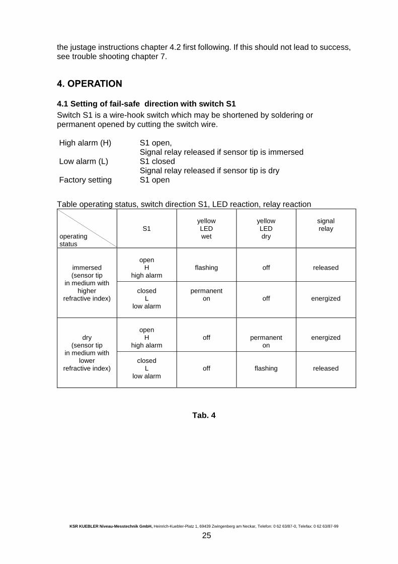
4.1 Setting of fail-safe direction with switch S1
Switch S1 is a wire-hook switch which may be shortened by soldering or permanent opened by cutting the switch wire. High alarm (H) S1 open,
Signal relay released if sensor tip is immersed Low alarm (L) S1 closed
Signal relay released if sensor tip is dry Factory setting S1 open
Table operating status, switch direction S1, LED reaction, relay reaction
operating status
S1
yellow LED wet
yellow LED dry
signal relay
immersed (sensor tip
in medium with higher
refractive index)
open
H high alarm
closed
L low alarm
flashing
permanent on
off
off
released
energized
dry (sensor tip
in medium with lower
refractive index)
open
H high alarm
closed
L low alarm
off
off
permanent on
flashing
energized
released
Tab. 4
KSR KUEBLER Niveau-Messtechnik GmbH, Heinrich-Kuebler-Platz 1, 69439 Zwingenberg am Neckar, Telefon: 0 62 63/87-0, Telefax: 0 62 63/87-99
26
S1 wsbrgn
P2
S2
P1
N/-L/+ S
upp
lyTEST
ST
TR
CAL
BEN
TrafoDC/DC
Rel1
Rel2
200
12
0
Abb. 20
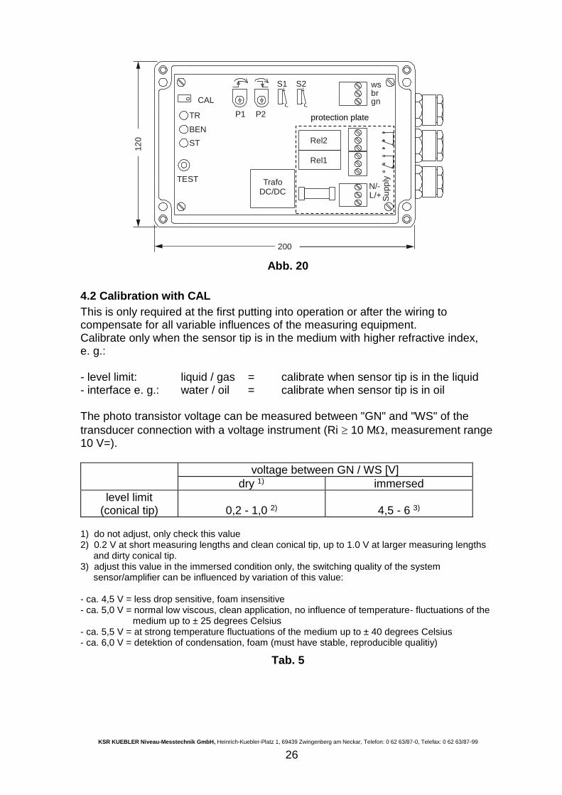
4.2 Calibration with CAL
This is only required at the first putting into operation or after the wiring to compensate for all variable influences of the measuring equipment. Calibrate only when the sensor tip is in the medium with higher refractive index, e. g.: - level limit: liquid / gas = calibrate when sensor tip is in the liquid - interface e. g.: water / oil = calibrate when sensor tip is in oil The photo transistor voltage can be measured between "GN" and "WS" of the
transducer connection with a voltage instrument (Ri 10 M, measurement range 10 V=).
voltage between GN / WS [V]
dry 1) immersed
level limit (conical tip)
0,2 - 1,0 2)
4,5 - 6 3)
1) do not adjust, only check this value 2) 0.2 V at short measuring lengths and clean conical tip, up to 1.0 V at larger measuring lengths and dirty conical tip. 3) adjust this value in the immersed condition only, the switching quality of the system sensor/amplifier can be influenced by variation of this value: - ca. 4,5 V = less drop sensitive, foam insensitive - ca. 5,0 V = normal low viscous, clean application, no influence of temperature- fluctuations of the medium up to ± 25 degrees Celsius - ca. 5,5 V = at strong temperature fluctuations of the medium up to ± 40 degrees Celsius - ca. 6,0 V = detektion of condensation, foam (must have stable, reproducible qualitiy)
Tab. 5
protection plate
KSR KUEBLER Niveau-Messtechnik GmbH, Heinrich-Kuebler-Platz 1, 69439 Zwingenberg am Neckar, Telefon: 0 62 63/87-0, Telefax: 0 62 63/87-99
27
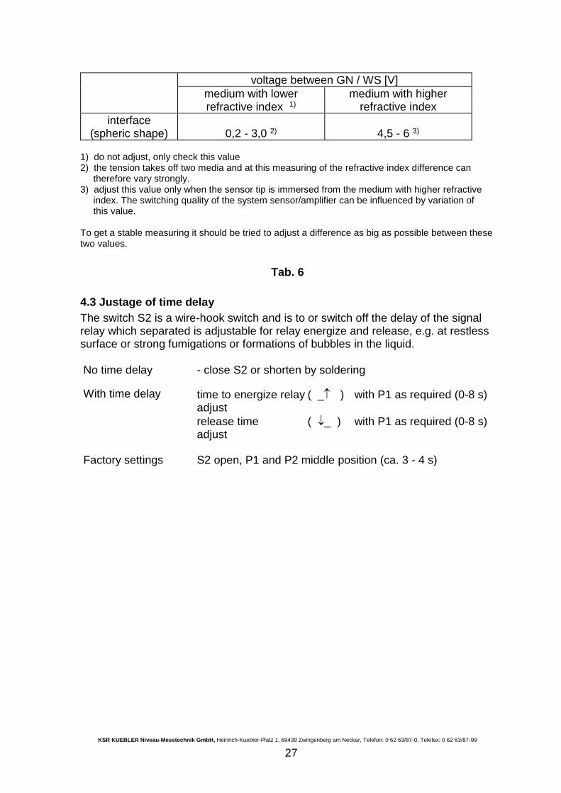
voltage between GN / WS [V]
medium with lower refractive index 1)
medium with higher refractive index
interface (spheric shape)
0,2 - 3,0 2)
4,5 - 6 3)
1) do not adjust, only check this value 2) the tension takes off two media and at this measuring of the refractive index difference can therefore vary strongly. 3) adjust this value only when the sensor tip is immersed from the medium with higher refractive index. The switching quality of the system sensor/amplifier can be influenced by variation of this value. To get a stable measuring it should be tried to adjust a difference as big as possible between these two values.
Tab. 6
4.3 Justage of time delay
The switch S2 is a wire-hook switch and is to or switch off the delay of the signal relay which separated is adjustable for relay energize and release, e.g. at restless surface or strong fumigations or formations of bubbles in the liquid. No time delay - close S2 or shorten by soldering
With time delay time to energize relay ( _ ) with P1 as required (0-8 s) adjust
release time ( _ ) with P1 as required (0-8 s) adjust
Factory settings S2 open, P1 and P2 middle position (ca. 3 - 4 s)
KSR KUEBLER Niveau-Messtechnik GmbH, Heinrich-Kuebler-Platz 1, 69439 Zwingenberg am Neckar, Telefon: 0 62 63/87-0, Telefax: 0 62 63/87-99
28
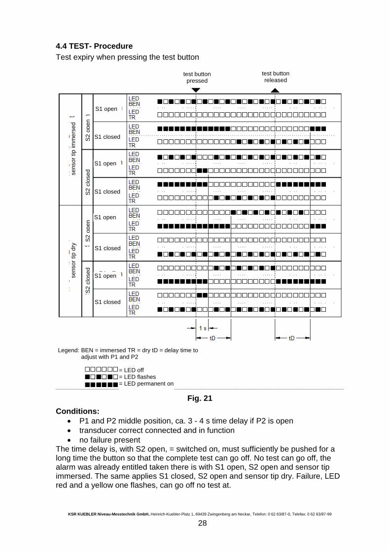
4.4 TEST- Procedure
Test expiry when pressing the test button
Fig. 21
Conditions:
P1 and P2 middle position, ca. 3 - 4 s time delay if P2 is open
transducer correct connected and in function
no failure present The time delay is, with S2 open, = switched on, must sufficiently be pushed for a long time the button so that the complete test can go off. No test can go off, the alarm was already entitled taken there is with S1 open, S2 open and sensor tip immersed. The same applies S1 closed, S2 open and sensor tip dry. Failure, LED red and a yellow one flashes, can go off no test at.
test button pressed
test button released
S1 open
S1 closed
S1 open
S1 closed
S1 open
S1 closed
S1 open
S1 closed
S2
clo
sed
S2
op
en
S2
clo
sed
S2
op
en
se
nso
r tip
dry
se
nso
r tip
im
me
rsed
Legend: BEN = immersed TR = dry tD = delay time to adjust with P1 and P2
= LED off = LED flashes = LED permanent on
KSR KUEBLER Niveau-Messtechnik GmbH, Heinrich-Kuebler-Platz 1, 69439 Zwingenberg am Neckar, Telefon: 0 62 63/87-0, Telefax: 0 62 63/87-99
29
The test function makes possible a checking the measuring chain switch amplifier separately and e.g. post-connected signal amplifier, signaling devices, control devices or a correction device at a connected and operating transducer and a reliable information gives about the proper function of the circuit board.
4.5 Operating characteristics relay signal
See Tab. 4.
4.6 Operating characteristics relay failure
The relay failure is energized in the normal operation and releases under the following conditions (fail safe behavior):
the supply voltage breakes down (>100 ms)
the internal supply voltage for the intrinsic safe circuit breakes down
short circuit (BR-WS) or interruption to IR-LED (BR)
short circuit (GN-WS) or interruption to phototransistor (GN) Behavior of the LED's see Tab. 4.
5. MAINTENANCE
The optoelectronic limit switch is maintenance-free in the rule. Stronger pollution is in the plant, however, recommends himself to make a maintenance instruction. Perhaps this can confine himself to an electrical measuring of the voltage between GN and WS of the transducer:
immersed (BEN) in the rule 5 V *)
dry (TRO) in the rule 0,2 - 1 V *) *) see Tab. 5 + 6. If the values adjusted at the putting into operation do not adapt, the condition of the glass tip should be checked. At pollution clean. Transducer send in at broken glass for the repair at the manufacturer (Caution! Into original packing). Please, use to the cleaning of the switch amplifier plastic case only a damp cloth. Clean not dripping wet!
6. GUARANTEE
We grant a guarantee period from 24 months on our products. Condition is the proper treatment and the use as agreed according to the operation instructions. The guarantee confines itself to material and construction faults at wear and spare parts. The manufacturer takes on the responsibility about the execution as agreed in accordance with customer details. The customer takes on the responsibility about the assembly as agreed and use.
KSR KUEBLER Niveau-Messtechnik GmbH, Heinrich-Kuebler-Platz 1, 69439 Zwingenberg am Neckar, Telefon: 0 62 63/87-0, Telefax: 0 62 63/87-99
30
7. RETURN-TO-MANUFACTURER
Because of legal regulations for environmental and personnel protection, devices sent to KSR Kuebler, which have been in contact with liquids can only be transported, checked an repaired if this is possible without danger for personnel and environment. KSR Kuebler can process your return only, if a declaration according this form is returned together with the product. If the device has been in contact/operated with toxic, acid, inflammable or water-polluting media, we have to ask you to:
check and clean, remove or neutralize any hazardous substances in the hollow rooms of the device.
return an acknowledgment, what the medium was and if it is dangerous.
8. Disposal
The customer/enduser is obliged to take care for the disposal within the legal regulations
KSR KUEBLER Niveau-Messtechnik GmbH, Heinrich-Kuebler-Platz 1, 69439 Zwingenberg am Neckar, Telefon: 0 62 63/87-0, Telefax: 0 62 63/87-99
31
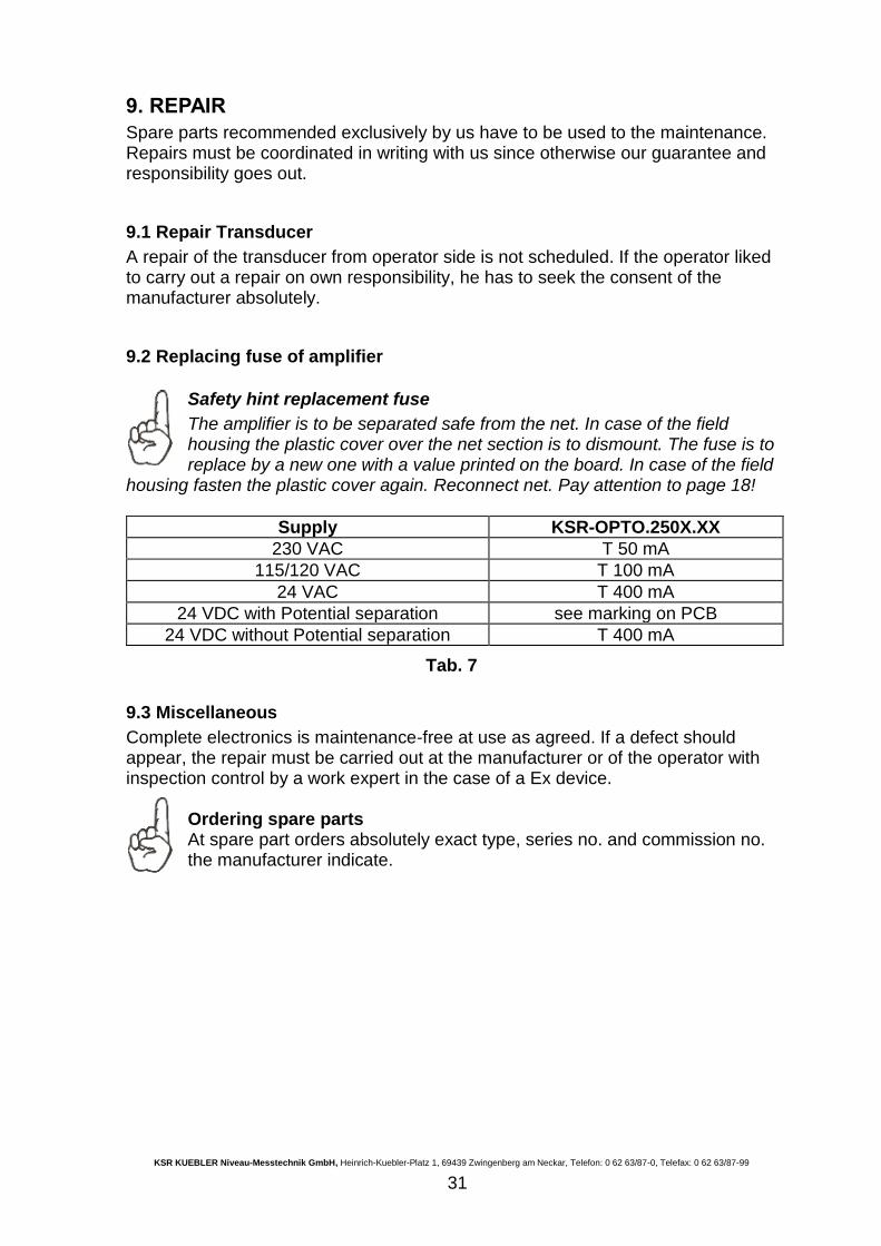
9. REPAIR
Spare parts recommended exclusively by us have to be used to the maintenance. Repairs must be coordinated in writing with us since otherwise our guarantee and responsibility goes out.
9.1 Repair Transducer
A repair of the transducer from operator side is not scheduled. If the operator liked to carry out a repair on own responsibility, he has to seek the consent of the manufacturer absolutely.
9.2 Replacing fuse of amplifier
Safety hint replacement fuse
The amplifier is to be separated safe from the net. In case of the field housing the plastic cover over the net section is to dismount. The fuse is to replace by a new one with a value printed on the board. In case of the field
housing fasten the plastic cover again. Reconnect net. Pay attention to page 18!
Supply KSR-OPTO.250X.XX
230 VAC T 50 mA
115/120 VAC T 100 mA
24 VAC T 400 mA
24 VDC with Potential separation see marking on PCB
24 VDC without Potential separation T 400 mA
Tab. 7
9.3 Miscellaneous
Complete electronics is maintenance-free at use as agreed. If a defect should appear, the repair must be carried out at the manufacturer or of the operator with inspection control by a work expert in the case of a Ex device.
Ordering spare parts At spare part orders absolutely exact type, series no. and commission no. the manufacturer indicate.
KSR KUEBLER Niveau-Messtechnik GmbH, Heinrich-Kuebler-Platz 1, 69439 Zwingenberg am Neckar, Telefon: 0 62 63/87-0, Telefax: 0 62 63/87-99
32
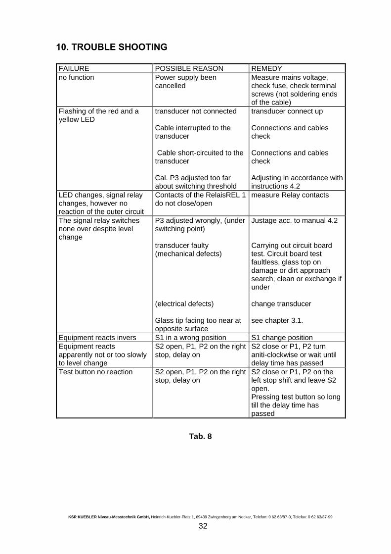
10. TROUBLE SHOOTING
FAILURE POSSIBLE REASON REMEDY
no function Power supply been cancelled
Measure mains voltage, check fuse, check terminal screws (not soldering ends of the cable)
Flashing of the red and a yellow LED
transducer not connected Cable interrupted to the transducer Cable short-circuited to the transducer Cal. P3 adjusted too far about switching threshold
transducer connect up Connections and cables check Connections and cables check Adjusting in accordance with instructions 4.2
LED changes, signal relay changes, however no reaction of the outer circuit
Contacts of the RelaisREL 1 do not close/open
measure Relay contacts
The signal relay switches none over despite level change
P3 adjusted wrongly, (under switching point) transducer faulty (mechanical defects) (electrical defects) Glass tip facing too near at opposite surface
Justage acc. to manual 4.2 Carrying out circuit board test. Circuit board test faultless, glass top on damage or dirt approach search, clean or exchange if under change transducer see chapter 3.1.
Equipment reacts invers S1 in a wrong position S1 change position
Equipment reacts apparently not or too slowly to level change
S2 open, P1, P2 on the right stop, delay on
S2 close or P1, P2 turn aniti-clockwise or wait until delay time has passed
Test button no reaction S2 open, P1, P2 on the right stop, delay on
S2 close or P1, P2 on the left stop shift and leave S2 open. Pressing test button so long till the delay time has passed
Tab. 8
KSR KUEBLER Niveau-Messtechnik GmbH, Heinrich-Kuebler-Platz 1, 69439 Zwingenberg am Neckar, Telefon: 0 62 63/87-0, Telefax: 0 62 63/87-99
33
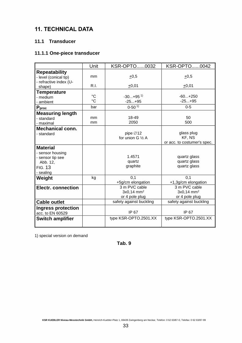
11. TECHNICAL DATA
11.1 Transducer
11.1.1 One-piece transducer
Unit KSR-OPTO......0032 KSR-OPTO......0042
Repeatability - level (conical tip) - refractive index (U- shape)
mm
R.I.
+0,5
+0,01
+0,5
+0,01
Temperature - medium - ambient
°C °C
-30...+95 1)
-25...+95
-60...+250 -25...+95
Pproc bar 0-50 1) 0-5
Measuring length - standard - maximal
mm mm
18-49 2050
50 500
Mechanical conn. - standard
pipe 12 for union G ½ A
glass plug
KF, NS or acc. to costumer's spec.
Material - sensor housing - sensor tip see Abb. 12,
FIG. 13
- sealing
1.4571 quartz
graphite
quartz glass quartz glass quartz glass
Weight kg 0,1 +5g/cm elongation
0,1 +1,3g/cm elongation
Electr. connection 3 m PVC cable 3x0,14 mm2
or 4 pole plug
3 m PVC cable 3x0,14 mm2
or 4 pole plug
Cable outlet safety against buckling safety against buckling
Ingress protection acc. to EN 60529
IP 67
IP 67
Switch amplifier
type KSR-OPTO.2501.XX type KSR-OPTO.2501.XX
1) special version on demand
Tab. 9
KSR KUEBLER Niveau-Messtechnik GmbH, Heinrich-Kuebler-Platz 1, 69439 Zwingenberg am Neckar, Telefon: 0 62 63/87-0, Telefax: 0 62 63/87-99
34
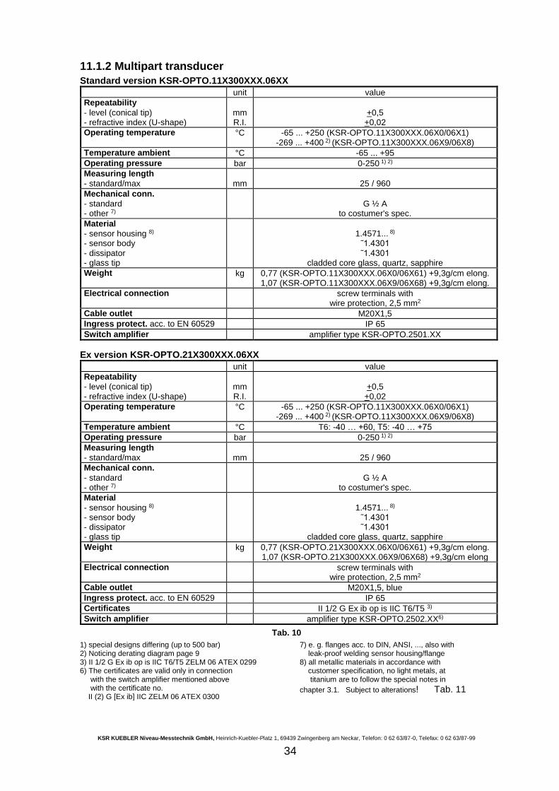
11.1.2 Multipart transducer
Standard version KSR-OPTO.11X300XXX.06XX
unit value
Repeatability
- level (conical tip) - refractive index (U-shape)
mm R.I.
+0,5
+0,02
Operating temperature °C -65 ... +250 (KSR-OPTO.11X300XXX.06X0/06X1) -269 ... +400 2) (KSR-OPTO.11X300XXX.06X9/06X8)
Temperature ambient °C -65 ... +95
Operating pressure bar 0-250 1) 2)
Measuring length
- standard/max
mm
25 / 960
Mechanical conn.
- standard - other 7)
G ½ A
to costumer's spec.
Material
- sensor housing 8) - sensor body - dissipator - glass tip
1.4571... 8)
˜1.4301 ˜1.4301
cladded core glass, quartz, sapphire
Weight kg 0,77 (KSR-OPTO.11X300XXX.06X0/06X61) +9,3g/cm elong. 1,07 (KSR-OPTO.11X300XXX.06X9/06X68) +9,3g/cm elong.
Electrical connection screw terminals with wire protection, 2,5 mm2
Cable outlet M20X1,5
Ingress protect. acc. to EN 60529 IP 65
Switch amplifier amplifier type KSR-OPTO.2501.XX
Ex version KSR-OPTO.21X300XXX.06XX
unit value
Repeatability
- level (conical tip) - refractive index (U-shape)
mm R.I.
+0,5
+0,02
Operating temperature °C -65 ... +250 (KSR-OPTO.11X300XXX.06X0/06X1) -269 ... +400 2) (KSR-OPTO.11X300XXX.06X9/06X8)
Temperature ambient °C T6: -40 … +60, T5: -40 … +75
Operating pressure bar 0-250 1) 2)
Measuring length
- standard/max
mm
25 / 960
Mechanical conn.
- standard - other 7)
G ½ A
to costumer's spec.
Material
- sensor housing 8) - sensor body - dissipator - glass tip
1.4571... 8)
˜1.4301 ˜1.4301
cladded core glass, quartz, sapphire
Weight kg 0,77 (KSR-OPTO.21X300XXX.06X0/06X61) +9,3g/cm elong. 1,07 (KSR-OPTO.21X300XXX.06X9/06X68) +9,3g/cm elong
Electrical connection screw terminals with wire protection, 2,5 mm2
Cable outlet M20X1,5, blue
Ingress protect. acc. to EN 60529 IP 65
Certificates II 1/2 G Ex ib op is IIC T6/T5 3)
Switch amplifier amplifier type KSR-OPTO.2502.XX6)
Tab. 10
1) special designs differing (up to 500 bar) 2) Noticing derating diagram page 9 3) II 1/2 G Ex ib op is IIC T6/T5 ZELM 06 ATEX 0299 6) The certificates are valid only in connection with the switch amplifier mentioned above with the certificate no. II (2) G [Ex ib] IIC ZELM 06 ATEX 0300
7) e. g. flanges acc. to DIN, ANSI, ..., also with leak-proof welding sensor housing/flange 8) all metallic materials in accordance with customer specification, no light metals, at titanium are to follow the special notes in
chapter 3.1. Subject to alterations! Tab. 11
KSR KUEBLER Niveau-Messtechnik GmbH, Heinrich-Kuebler-Platz 1, 69439 Zwingenberg am Neckar, Telefon: 0 62 63/87-0, Telefax: 0 62 63/87-99
35
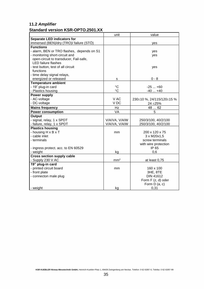
11.2 Amplifier
Standard version KSR-OPTO.2501.XX unit value
Separate LED indicators for immersed (BEN)/dry (TRO)/ failure (STÖ)
yes
Functions - alarm, BEN or TRO flashes, depends on S1 - monitoring short-circuit and open-circuit to transducer, Fail-safe, LED failure flashes - test button, test of all circuit functions - time delay signal relays, energized or released
s
yes yes
yes
0 - 8
Temperature ambient - 19” plug-in card - Plastics housing
°C °C
-25 ... +60 -40 ... +40
Power supply - AC-voltage - DC-voltage
V AC V DC
23010 %, 24/115/12015 %
24 25%
Mains frequency Hz 48 … 62
Power consumption VA 5
Output - signal, relay, 1 x SPDT - failure, relay, 1 x SPDT
V/A/VA, V/A/W V/A/VA, V/A/W
250/3/100, 40/2/100 250/3/100, 40/2/100
Plastics housing - housing H x B x T - cable inlet - terminals - ingress protect. acc. to EN 60529 - weight
mm
kg
200 x 120 x 75 3 x M20x1,5
screw terminals with wire protection
IP 65 0,6
Cross section supply cable - Supply 230 V AC
mm2
at least 0,75
19” plug-in card - printed circuit board - front plate - connecton male plug - weight
mm
kg
160 x 100 3HE, 8TE DIN 41612
Form F (z, d) oder Form D (a, c)
0,31
KSR KUEBLER Niveau-Messtechnik GmbH, Heinrich-Kuebler-Platz 1, 69439 Zwingenberg am Neckar, Telefon: 0 62 63/87-0, Telefax: 0 62 63/87-99
36
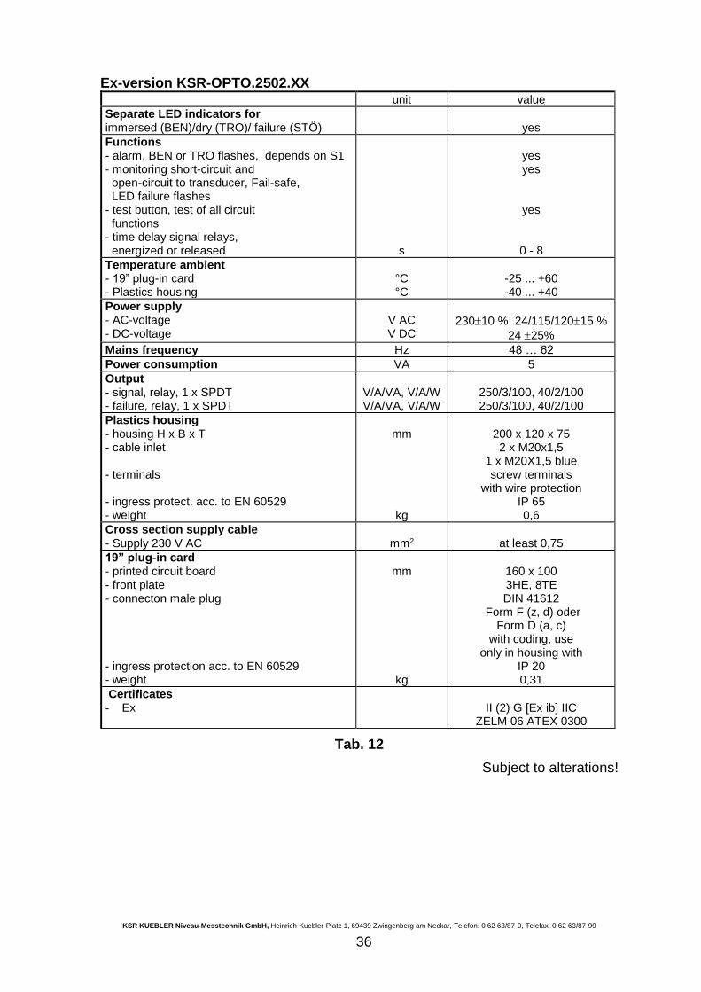
Ex-version KSR-OPTO.2502.XX unit value
Separate LED indicators for immersed (BEN)/dry (TRO)/ failure (STÖ)
yes
Functions - alarm, BEN or TRO flashes, depends on S1 - monitoring short-circuit and open-circuit to transducer, Fail-safe, LED failure flashes - test button, test of all circuit functions - time delay signal relays, energized or released
s
yes yes
yes
0 - 8
Temperature ambient - 19” plug-in card - Plastics housing
°C °C
-25 ... +60 -40 ... +40
Power supply - AC-voltage - DC-voltage
V AC V DC
23010 %, 24/115/12015 %
24 25%
Mains frequency Hz 48 … 62
Power consumption VA 5
Output - signal, relay, 1 x SPDT - failure, relay, 1 x SPDT
V/A/VA, V/A/W V/A/VA, V/A/W
250/3/100, 40/2/100 250/3/100, 40/2/100
Plastics housing - housing H x B x T - cable inlet - terminals - ingress protect. acc. to EN 60529 - weight
mm
kg
200 x 120 x 75 2 x M20x1,5
1 x M20X1,5 blue screw terminals
with wire protection IP 65 0,6
Cross section supply cable - Supply 230 V AC
mm2
at least 0,75
19” plug-in card - printed circuit board - front plate - connecton male plug - ingress protection acc. to EN 60529 - weight
mm
kg
160 x 100 3HE, 8TE DIN 41612
Form F (z, d) oder Form D (a, c)
with coding, use only in housing with
IP 20 0,31
Certificates - Ex
II (2) G [Ex ib] IIC
ZELM 06 ATEX 0300
Tab. 12
Subject to alterations!
KSR KUEBLER Niveau-Messtechnik GmbH, Heinrich-Kuebler-Platz 1, 69439 Zwingenberg am Neckar, Telefon: 0 62 63/87-0, Telefax: 0 62 63/87-99
37
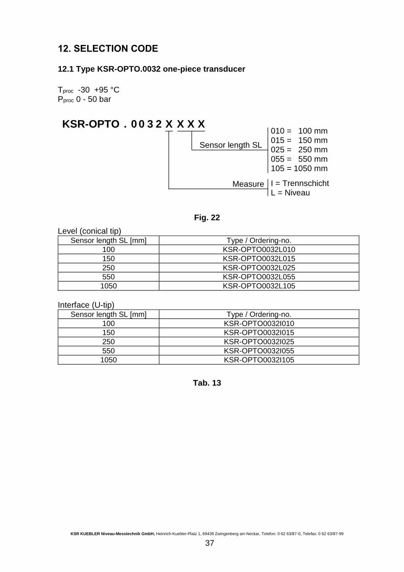
12. SELECTION CODE
12.1 Type KSR-OPTO.0032 one-piece transducer
Tproc -30 +95 °C Pproc 0 - 50 bar
Fig. 22
Level (conical tip) Sensor length SL [mm] Type / Ordering-no.
100 KSR-OPTO0032L010
150 KSR-OPTO0032L015
250 KSR-OPTO0032L025
550 KSR-OPTO0032L055
1050 KSR-OPTO0032L105
Interface (U-tip)
Sensor length SL [mm] Type / Ordering-no.
100 KSR-OPTO0032I010
150 KSR-OPTO0032I015
250 KSR-OPTO0032I025
550 KSR-OPTO0032I055
1050 KSR-OPTO0032I105
Tab. 13
KSR-OPTO . 0 0 3 2 X X X X 010 = 100 mm 015 = 150 mm 025 = 250 mm 055 = 550 mm 105 = 1050 mm
Sensor length SL
Measure
I = Trennschicht L = Niveau
KSR KUEBLER Niveau-Messtechnik GmbH, Heinrich-Kuebler-Platz 1, 69439 Zwingenberg am Neckar, Telefon: 0 62 63/87-0, Telefax: 0 62 63/87-99
38
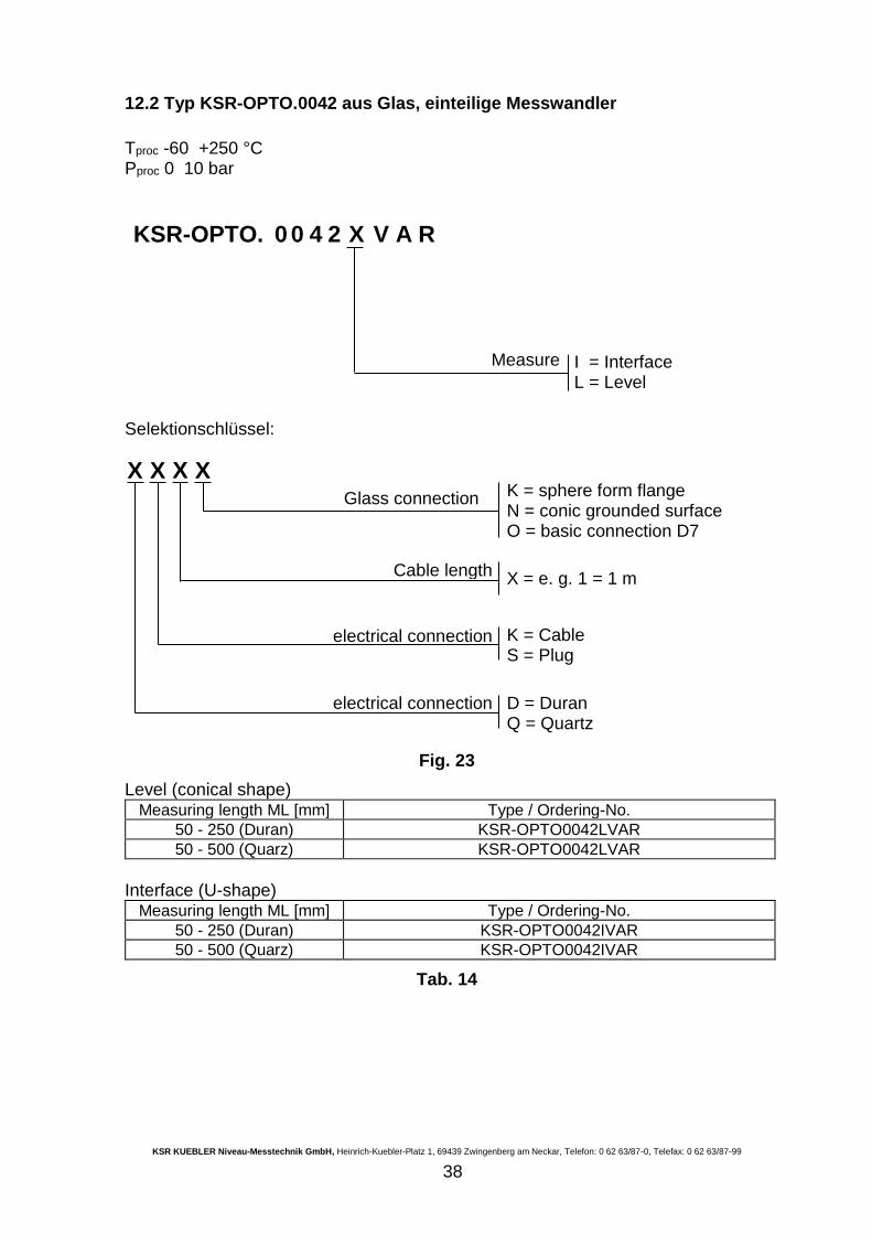
12.2 Typ KSR-OPTO.0042 aus Glas, einteilige Messwandler
Tproc -60 +250 °C Pproc 0 10 bar
Selektionschlüssel:
Fig. 23
Level (conical shape) Measuring length ML [mm] Type / Ordering-No.
50 - 250 (Duran) KSR-OPTO0042LVAR
50 - 500 (Quarz) KSR-OPTO0042LVAR
Interface (U-shape)
Measuring length ML [mm] Type / Ordering-No.
50 - 250 (Duran) KSR-OPTO0042IVAR
50 - 500 (Quarz) KSR-OPTO0042IVAR
Tab. 14
KSR-OPTO. 0 0 4 2 X V A R
Measure
I = Interface L = Level
X X X X Glass connection
K = sphere form flange N = conic grounded surface O = basic connection D7
Cable length
X = e. g. 1 = 1 m
electrical connection
K = Cable S = Plug
electrical connection
D = Duran Q = Quartz
KSR KUEBLER Niveau-Messtechnik GmbH, Heinrich-Kuebler-Platz 1, 69439 Zwingenberg am Neckar, Telefon: 0 62 63/87-0, Telefax: 0 62 63/87-99
39
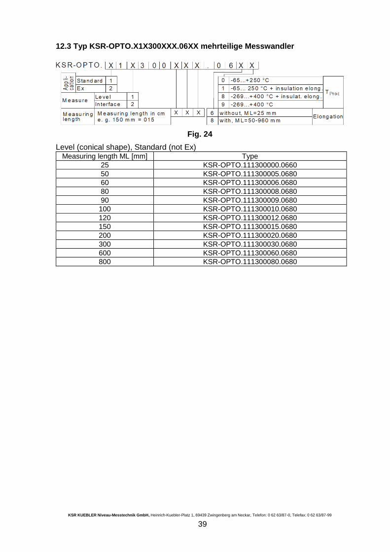
12.3 Typ KSR-OPTO.X1X300XXX.06XX mehrteilige Messwandler
Fig. 24
Level (conical shape), Standard (not Ex) Measuring length ML [mm] Type
25 KSR-OPTO.111300000.0660
50 KSR-OPTO.111300005.0680
60 KSR-OPTO.111300006.0680
80 KSR-OPTO.111300008.0680
90 KSR-OPTO.111300009.0680
100 KSR-OPTO.111300010.0680
120 KSR-OPTO.111300012.0680
150 KSR-OPTO.111300015.0680
200 KSR-OPTO.111300020.0680
300 KSR-OPTO.111300030.0680
600 KSR-OPTO.111300060.0680
800 KSR-OPTO.111300080.0680
KSR KUEBLER Niveau-Messtechnik GmbH, Heinrich-Kuebler-Platz 1, 69439 Zwingenberg am Neckar, Telefon: 0 62 63/87-0, Telefax: 0 62 63/87-99
40
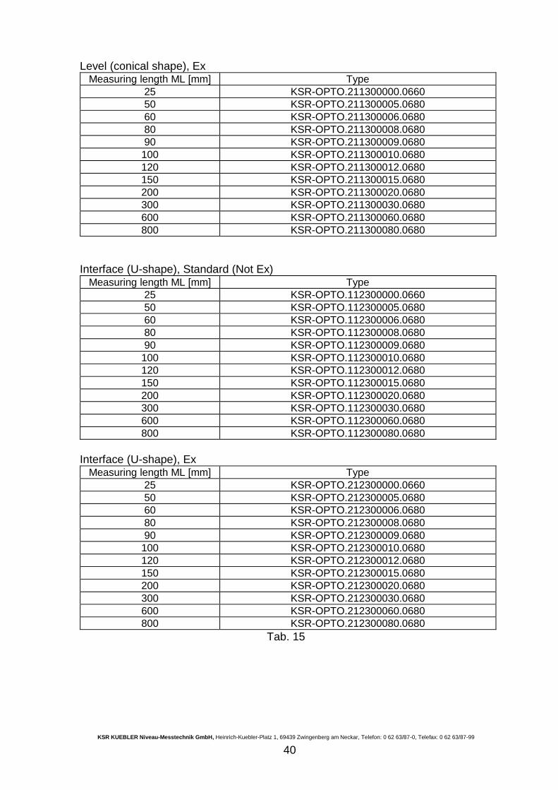
Level (conical shape), Ex Measuring length ML [mm] Type
25 KSR-OPTO.211300000.0660
50 KSR-OPTO.211300005.0680
60 KSR-OPTO.211300006.0680
80 KSR-OPTO.211300008.0680
90 KSR-OPTO.211300009.0680
100 KSR-OPTO.211300010.0680
120 KSR-OPTO.211300012.0680
150 KSR-OPTO.211300015.0680
200 KSR-OPTO.211300020.0680
300 KSR-OPTO.211300030.0680
600 KSR-OPTO.211300060.0680
800 KSR-OPTO.211300080.0680
Interface (U-shape), Standard (Not Ex)
Measuring length ML [mm] Type
25 KSR-OPTO.112300000.0660
50 KSR-OPTO.112300005.0680
60 KSR-OPTO.112300006.0680
80 KSR-OPTO.112300008.0680
90 KSR-OPTO.112300009.0680
100 KSR-OPTO.112300010.0680
120 KSR-OPTO.112300012.0680
150 KSR-OPTO.112300015.0680
200 KSR-OPTO.112300020.0680
300 KSR-OPTO.112300030.0680
600 KSR-OPTO.112300060.0680
800 KSR-OPTO.112300080.0680
Interface (U-shape), Ex
Measuring length ML [mm] Type
25 KSR-OPTO.212300000.0660
50 KSR-OPTO.212300005.0680
60 KSR-OPTO.212300006.0680
80 KSR-OPTO.212300008.0680
90 KSR-OPTO.212300009.0680
100 KSR-OPTO.212300010.0680
120 KSR-OPTO.212300012.0680
150 KSR-OPTO.212300015.0680
200 KSR-OPTO.212300020.0680
300 KSR-OPTO.212300030.0680
600 KSR-OPTO.212300060.0680
800 KSR-OPTO.212300080.0680
Tab. 15
KSR KUEBLER Niveau-Messtechnik GmbH, Heinrich-Kuebler-Platz 1, 69439 Zwingenberg am Neckar, Telefon: 0 62 63/87-0, Telefax: 0 62 63/87-99
41
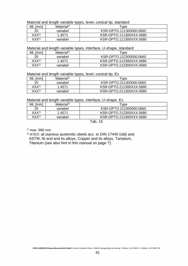
Material and length variable types, level, conical tip, standard ML [mm] Material2) Type
25 variabel KSR-OPTO.111300000.0660
XXX1) 1.4571 KSR-OPTO.111300XXX.0680
XXX1) variabel KSR-OPTO.111300XXX.0680
Material and length variable types, interface, U-shape, standard
ML [mm] Material2) Type
25 variabel KSR-OPTO.112300000.0660
XXX1) 1.4571 KSR-OPTO.112300XXX.0680
XXX1) variabel KSR-OPTO.112300XXX.0680
Material and length variable types, level, conical tip, Ex
ML [mm] Material2) Type
25 variabel KSR-OPTO.211300000.0660
XXX1) 1.4571 KSR-OPTO.211300XXX.0680
XXX1) variabel KSR-OPTO.211300XXX.0680
Material and length variable types, interface, U-shape, Ex
ML [mm] Material2) Type
25 variabel KSR-OPTO.212300000.0660
XXX1) 1.4571 KSR-OPTO.212300XXX.0680
XXX1) variabel KSR-OPTO.212300XXX.0680
Tab. 15 1) max. 960 mm 2) ATEX: all stainless austenitic steels acc. to DIN 17440 (old) and ASTM, Ni and and its alloys, Copper and its alloys, Tantalum, Titanium (see also hint in this manual on page 7).
KSR KUEBLER Niveau-Messtechnik GmbH, Heinrich-Kuebler-Platz 1, 69439 Zwingenberg am Neckar, Telefon: 0 62 63/87-0, Telefax: 0 62 63/87-99
42
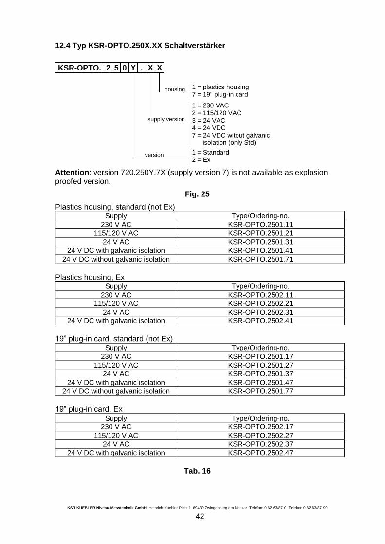
12.4 Typ KSR-OPTO.250X.XX Schaltverstärker
Attention: version 720.250Y.7X (supply version 7) is not available as explosion proofed version.
Fig. 25
Plastics housing, standard (not Ex) Supply Type/Ordering-no.
230 V AC KSR-OPTO.2501.11
115/120 V AC KSR-OPTO.2501.21
24 V AC KSR-OPTO.2501.31
24 V DC with galvanic isolation KSR-OPTO.2501.41
24 V DC without galvanic isolation KSR-OPTO.2501.71
Plastics housing, Ex
Supply Type/Ordering-no.
230 V AC KSR-OPTO.2502.11
115/120 V AC KSR-OPTO.2502.21
24 V AC KSR-OPTO.2502.31
24 V DC with galvanic isolation KSR-OPTO.2502.41
19” plug-in card, standard (not Ex)
Supply Type/Ordering-no.
230 V AC KSR-OPTO.2501.17
115/120 V AC KSR-OPTO.2501.27
24 V AC KSR-OPTO.2501.37
24 V DC with galvanic isolation KSR-OPTO.2501.47
24 V DC without galvanic isolation KSR-OPTO.2501.77
19” plug-in card, Ex
Supply Type/Ordering-no.
230 V AC KSR-OPTO.2502.17
115/120 V AC KSR-OPTO.2502.27
24 V AC KSR-OPTO.2502.37
24 V DC with galvanic isolation KSR-OPTO.2502.47
Tab. 16
KSR-OPTO. 2 5 0 Y0
. X0
X0
1 = plastics housing 7 = 19" plug-in card
housing
1 = 230 VAC 2 = 115/120 VAC 3 = 24 VAC 4 = 24 VDC 7 = 24 VDC witout galvanic isolation (only Std) 1 = Standard 2 = Ex
supply version
version
KSR KUEBLER Niveau-Messtechnik GmbH, Heinrich-Kuebler-Platz 1, 69439 Zwingenberg am Neckar, Telefon: 0 62 63/87-0, Telefax: 0 62 63/87-99
43
13 Safety Manual
Functional safety acc. to IEC 61508 / IEC 61511 Optoelectronic Limit Switch type KSR-OPTO.X1X300XXX.06XX in connection with Amplifier type KSR-OPTO.250X.XX.
13.1 General
13.1.1 Validity
This safety manual applies to Optoelectronic Limit Switch type KSR-OPTO.X1X300XXX.06XX in connection with Amplifier type KSR-OPTO.250X.XX, called “measuring system”. Application range The measuring system can be used for the following functions which meet the specific requirements of the safety technology:
overfill protection
dry run protection
detection of an individual level
The functions can be used in the mode of operation with low demand mode as well as in the mode of operation with high demand or continuous mode. The measuring system is qualified in all modes to meet the requirement degree SIL1 acc. to IEC 61508-2 / IEC 61511-1. The lifetime of the measuring system for the use in safety applications is outlined for 10 years. In safety-related systems with an architecture 1oo2D and the requirement SIL2, the measuring system must be combined with a comparator chain, so the complete measuring system fulfills in the mode of operation with low demand mode
PFD = PFDCH1 . PFDCH2 + CC
PDF<10-2
The safety-related characteristics must be calculated separately.
13.1.2 Relevant standards
IEC 61508 Part 1, 2, 4 Functional safety of electrical / electronic / programmable electronic systems IEC 61511-1 Functional safety - safety instrumented systems for the process industry sector - Part 1: Framework, definitions, system, hardware and software requirements
KSR KUEBLER Niveau-Messtechnik GmbH, Heinrich-Kuebler-Platz 1, 69439 Zwingenberg am Neckar, Telefon: 0 62 63/87-0, Telefax: 0 62 63/87-99
44
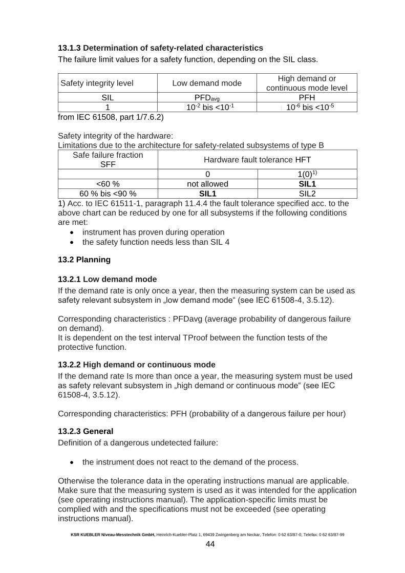
13.1.3 Determination of safety-related characteristics
The failure limit values for a safety function, depending on the SIL class.
Safety integrity level Low demand mode High demand or
continuous mode level
SIL PFDavg PFH
1 10-2 bis <10-1 10-6 bis <10-5
from IEC 61508, part 1/7.6.2) Safety integrity of the hardware: Limitations due to the architecture for safety-related subsystems of type B
Safe failure fraction SFF
Hardware fault tolerance HFT
0 1(0)1)
<60 % not allowed SIL1
60 % bis <90 % SIL1 SIL2
1) Acc. to IEC 61511-1, paragraph 11.4.4 the fault tolerance specified acc. to the above chart can be reduced by one for all subsystems if the following conditions are met:
instrument has proven during operation
the safety function needs less than SIL 4
13.2 Planning
13.2.1 Low demand mode
If the demand rate is only once a year, then the measuring system can be used as safety relevant subsystem in „low demand mode“ (see IEC 61508-4, 3.5.12). Corresponding characteristics : PFDavg (average probability of dangerous failure on demand). It is dependent on the test interval TProof between the function tests of the protective function.
13.2.2 High demand or continuous mode
If the demand rate Is more than once a year, the measuring system must be used as safety relevant subsystem in „high demand or continuous mode“ (see IEC 61508-4, 3.5.12). Corresponding characteristics: PFH (probability of a dangerous failure per hour)
13.2.3 General
Definition of a dangerous undetected failure:
the instrument does not react to the demand of the process. Otherwise the tolerance data in the operating instructions manual are applicable. Make sure that the measuring system is used as it was intended for the application (see operating instructions manual). The application-specific limits must be complied with and the specifications must not be exceeded (see operating instructions manual).
KSR KUEBLER Niveau-Messtechnik GmbH, Heinrich-Kuebler-Platz 1, 69439 Zwingenberg am Neckar, Telefon: 0 62 63/87-0, Telefax: 0 62 63/87-99
45
13.3 Set-up
13.3.1 Mounting and installation
The prevailing plant conditions influence the safety of the measuring system. Therefore note the mounting and installation instructions of the appropriate operating instructions manual and references in this Safety manual chapter 2.3.1 mounting and installation. Therefore the assembly and installation hint are to be considered according to the operating instructions, in particular the safety references in chapters 3., 3.1 und 3.3. To absolutely avoid for a safe function are:
lignment of the measuring system with first start-up and exchange of the transducer or the amplifier (see manual)
Examination of the complete function by dive in / out-dip or if not possible through pressing the test key (see manual)
Examination on perfect condition of the glass tip (cleanly, not damaged)
lateral load of the measuring body avoid (possibly attach mechanical protection)
attach deflecting plate from glass tip with high flow rates and particles
if with the transducer a transport lock is attached in case of heavy flange, remove only briefly before the installation the transport lock
include measuring system after mounting into the pressure test also
Operation only by experienced operators
13.4 Reaction during operation and in case of failure
In case of detected failures or fault signals, the entire measuring system must be switched out of service and the process held in a safe condition by means of other measures.
13.5 Recurring function test
The recurring function test serves to reveal potential dangerous errors that are otherwise not discernible. The function of the measuring system must be checked at adequate intervals. The operator is responsible for choosing the type of test and the intervals in the stated time frame. The time intervals depend upon the applied PFDavg value acc. to the chart and diagram in the paragraph „Safety-related characteristics“. The test must be carried out in a ways that verifies the flawless operation of the safety functions in conjunction with all system components. This is ensured by a controlled reaching of the response height during a filling. If the function test proves negative, the entire measuring system must be switched out of service and the process held in a safe condition by means of other measures.
KSR KUEBLER Niveau-Messtechnik GmbH, Heinrich-Kuebler-Platz 1, 69439 Zwingenberg am Neckar, Telefon: 0 62 63/87-0, Telefax: 0 62 63/87-99
46
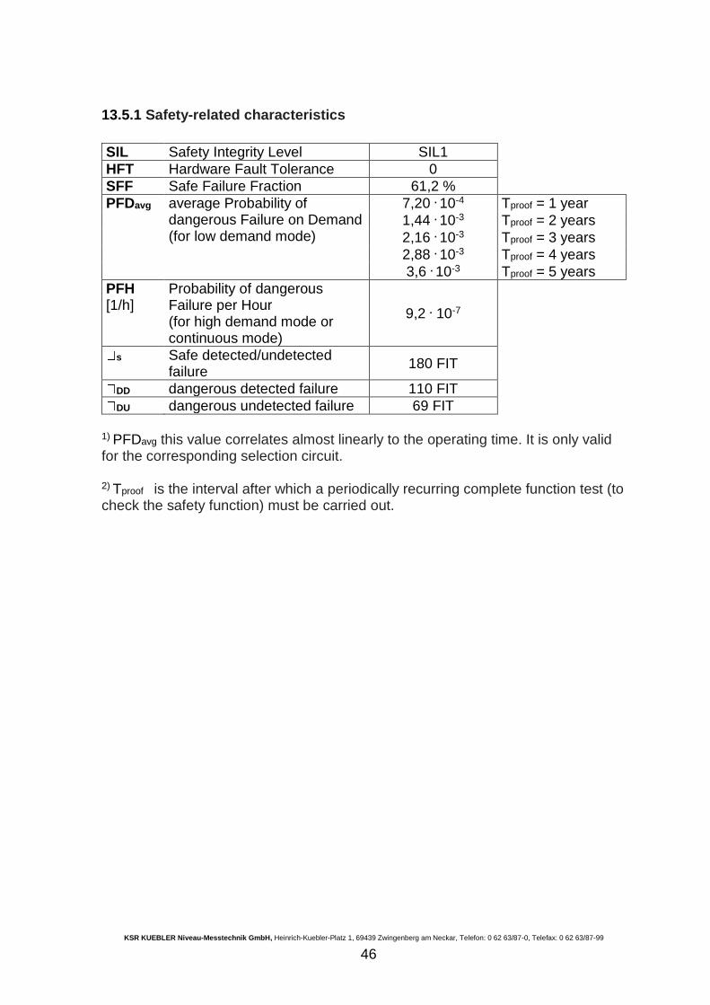
13.5.1 Safety-related characteristics
SIL Safety Integrity Level SIL1
HFT Hardware Fault Tolerance 0
SFF Safe Failure Fraction 61,2 %
PFDavg average Probability of dangerous Failure on Demand (for low demand mode)
7,20 . 10-4 Tproof = 1 year
1,44 . 10-3 Tproof = 2 years
2,16 . 10-3 Tproof = 3 years
2,88 . 10-3 Tproof = 4 years
3,6 . 10-3 Tproof = 5 years
PFH [1/h]
Probability of dangerous Failure per Hour (for high demand mode or continuous mode)
9,2 . 10-7
s Safe detected/undetected failure
180 FIT
DD dangerous detected failure 110 FIT
DU dangerous undetected failure 69 FIT
1) PFDavg this value correlates almost linearly to the operating time. It is only valid for the corresponding selection circuit. 2) Tproof is the interval after which a periodically recurring complete function test (to check the safety function) must be carried out.
KSR KUEBLER Niveau-Messtechnik GmbH, Heinrich-Kuebler-Platz 1, 69439 Zwingenberg am Neckar, Telefon: 0 62 63/87-0, Telefax: 0 62 63/87-99
47
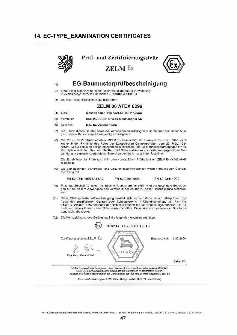
14. EC-TYPE_EXAMINATION CERTIFICATES
KSR KUEBLER Niveau-Messtechnik GmbH, Heinrich-Kuebler-Platz 1, 69439 Zwingenberg am Neckar, Telefon: 0 62 63/87-0, Telefax: 0 62 63/87-99
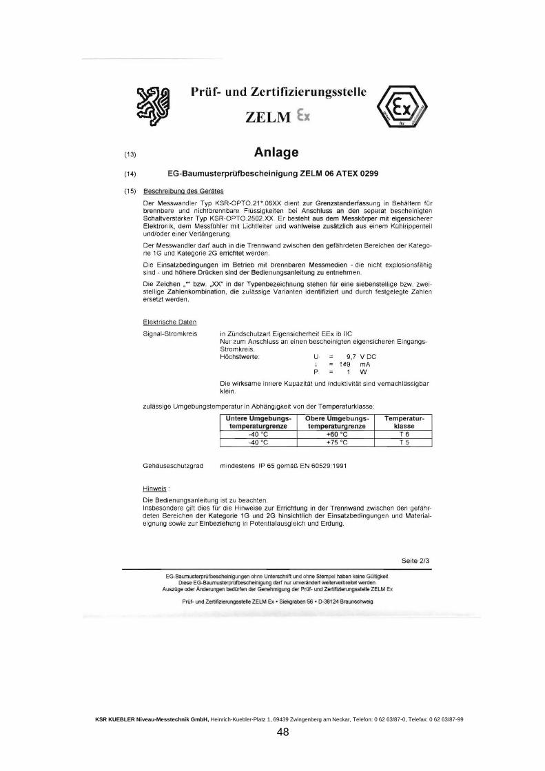
48
KSR KUEBLER Niveau-Messtechnik GmbH, Heinrich-Kuebler-Platz 1, 69439 Zwingenberg am Neckar, Telefon: 0 62 63/87-0, Telefax: 0 62 63/87-99
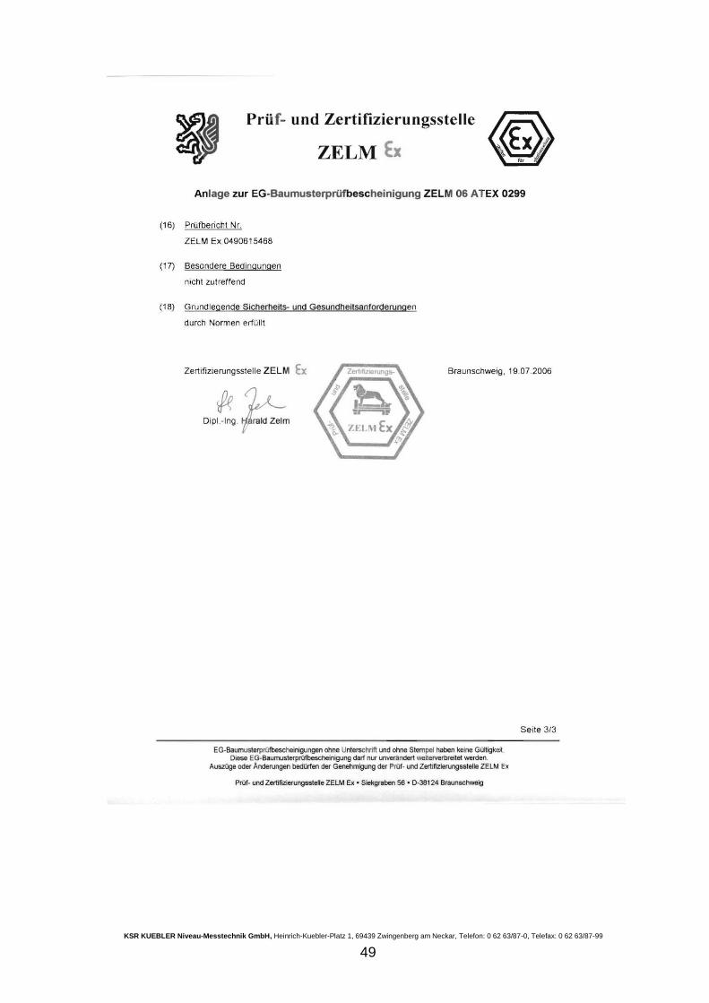
49
KSR KUEBLER Niveau-Messtechnik GmbH, Heinrich-Kuebler-Platz 1, 69439 Zwingenberg am Neckar, Telefon: 0 62 63/87-0, Telefax: 0 62 63/87-99
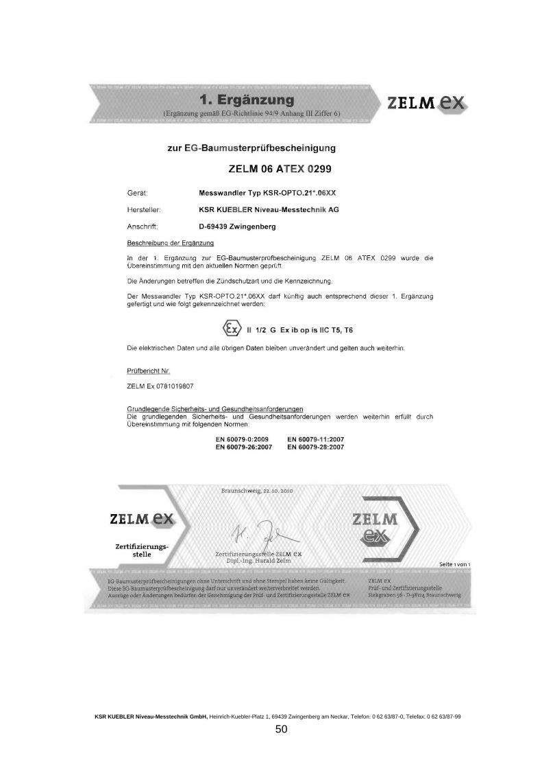
50
KSR KUEBLER Niveau-Messtechnik GmbH, Heinrich-Kuebler-Platz 1, 69439 Zwingenberg am Neckar, Telefon: 0 62 63/87-0, Telefax: 0 62 63/87-99
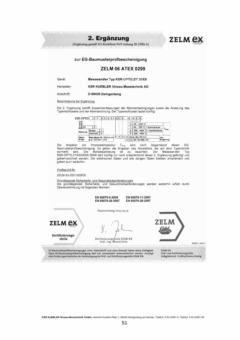
51
KSR KUEBLER Niveau-Messtechnik GmbH, Heinrich-Kuebler-Platz 1, 69439 Zwingenberg am Neckar, Telefon: 0 62 63/87-0, Telefax: 0 62 63/87-99
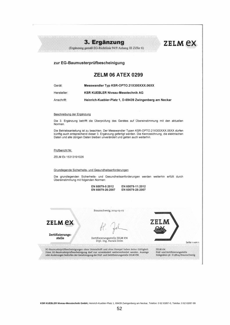
52
KSR KUEBLER Niveau-Messtechnik GmbH, Heinrich-Kuebler-Platz 1, 69439 Zwingenberg am Neckar, Telefon: 0 62 63/87-0, Telefax: 0 62 63/87-99
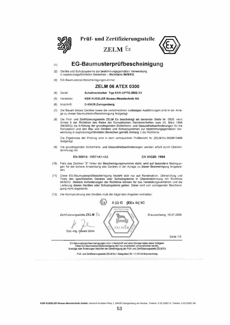
53
KSR KUEBLER Niveau-Messtechnik GmbH, Heinrich-Kuebler-Platz 1, 69439 Zwingenberg am Neckar, Telefon: 0 62 63/87-0, Telefax: 0 62 63/87-99
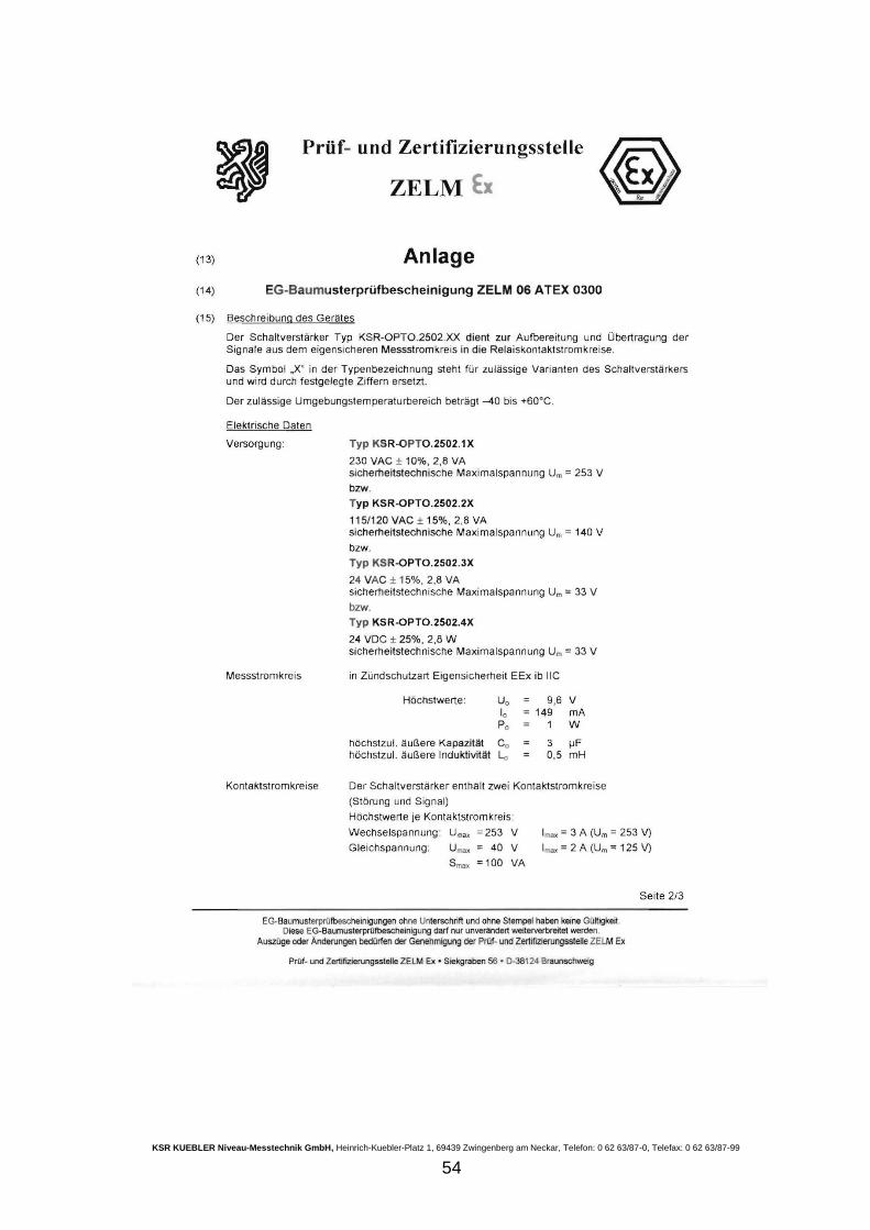
54
KSR KUEBLER Niveau-Messtechnik GmbH, Heinrich-Kuebler-Platz 1, 69439 Zwingenberg am Neckar, Telefon: 0 62 63/87-0, Telefax: 0 62 63/87-99
55
KSR KUEBLER Niveau-Messtechnik GmbH, Heinrich-Kuebler-Platz 1, 69439 Zwingenberg am Neckar, Telefon: 0 62 63/87-0, Telefax: 0 62 63/87-99
56
KSR KUEBLER Niveau-Messtechnik GmbH, Heinrich-Kuebler-Platz 1, 69439 Zwingenberg am Neckar, Telefon: 0 62 63/87-0, Telefax: 0 62 63/87-99
57
KSR KUEBLER Niveau-Messtechnik GmbH, Heinrich-Kuebler-Platz 1, 69439 Zwingenberg am Neckar, Telefon: 0 62 63/87-0, Telefax: 0 62 63/87-99
58
KSR KUEBLER Niveau-Messtechnik GmbH, Heinrich-Kuebler-Platz 1, 69439 Zwingenberg am Neckar, Telefon: 0 62 63/87-0, Telefax: 0 62 63/87-99
59
aI(SRXITAEBLER
vä A divison o{ EE wKA Group
E U -Konfo rm itätserkläru n gEU Declaration of Conformity
Wir erklären in alleiniger Verantwortung, dass die mit CE gekennzeichneten ProdukteWe declare under our sole responsibility that the CE marked products
Typenbezeich nu ng:Type Designation:
Beschreibung:Description:
2O11t65tEU Gefährliche Stoffe (RoHS)Hazardous substances (RoH S)
ZOl4l3OlEU Elektromagnetische Verträglic,hkeitr')tr tectromag netrc Com p att bt I tty'
die grundlegenden Schutzanforderungen der folgenden Richtlinien erfüllen: Harmonisierte Normen.comply with the essenfiai protection requirements of the directives: Harmonized standards:
Dokument Nr.:Document No.:
KSR Ku
ThomasKSR Ku
69439 ZwlngenbergDeutschland
1131 02
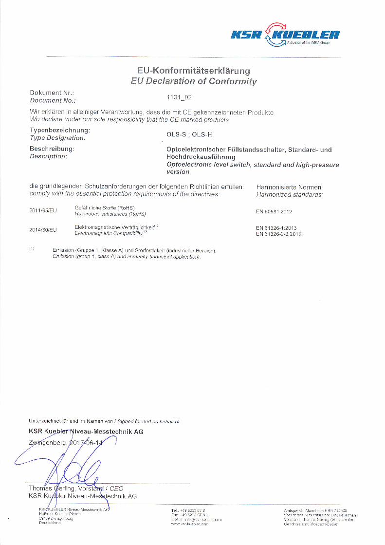
OLS-S;OLS-H
Optoelektronischer Füllstandsschalter, Standard- undHochdruckausführungOptoelectronic level switch, standard and high-pressureversion
EN 50581:2012
EN 61326-1:2013EN 61326-2-3:2013
Emission (Gruppe 1, Klasse A) und Störfestigkeit (industrieller Bereich)Emission (group 1, c/ass A) and immunity (industrial application).
-Messtechnik AG
I CEO
Tel.: +49 6263 B7-0Fax: +49 6263 87-99E-lVail: [email protected]
Amtsgericht I\,4annheim HRB 714806Vorsiiz des Aufsichtsrates: Dlrk FellermannVorstand: Thomas Gerling (Vorsitzender)Gerichlsstand: l\,4osbach/Baden
Unterzeichnet für und im Namen von I Siqned for and on behalf of
ler Nivea
-1
hnik AG
a,(sRXKAEBLER
vä A dut on of l5e WIKA G.oup
E U-Konfo rm itätserkläru n gEU Declaration of Conformity
Wir erklären in alleiniger Verantwortung, dass die mit CE gekennzeichneten ProdukteWe declare under our sole responsibility that the CE markecl products
Typenbezeichnung:Type Designation:
Beschreibung:Description:
Dokument Nr.:Document No.:
2011t65tEU
2014130tEU
2014/34tEU
Gefäh rliche Stoffe (RoHS)H aza rd o u s subsfances (RoHS)
Elektromagnetische Verträglichkeit')Ele ctrom ag netic Com patib i lity' t'
Explosionssch utz (ATEX)('z)ß)Ex p I osi o n p rotecti o n ( AT EXy't Gt
1116 02
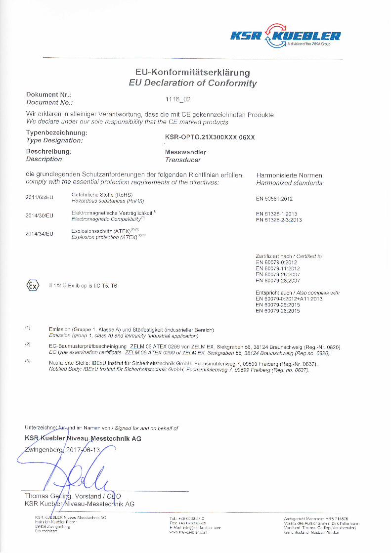
KSR-O PTO.2 1 X30oXXX.06XX
MesswandlerTransducer
Te .r +49 6263 B7-0Fax: +49 6263 87-99E lvlail: info@ksr-k!ebler. comww.ksT-kueb er com
EN 50581:2012
EN 61326-1 :2013EN 61326-2-3:2013
die grundlegenden Schutzanforderungen der folgenden Richtlinien erfüllen. Harmonisierte Normen.comply with the essential protection requirements of the directives: Harmonized standards:
(3)
ll 112 G Ex ib op is llC T5, T6
Zefüfizierl. nach I Certified toEN 60079-0:2012EN 60079-1 1:2012EN 60079-26:2007EN 60079-28.2007
Entspricht auch / A/so complies withEN 60079-0:20 12+41 1 .2013EN 60079-26:2015EN 60079-28:20'15
Emission (Gruppe 1, Klasse A) und Störfestigkeit (industrieller Bereich)Emission (group 1, c/ass A) and immunity (industrial application)
EG-Baumusterprüfbescheinigung ZELM06ATEX02ggvonZELMEX,Siekgraben56,38l24Braunschweig(Reg.-Nr.0820)EC type examination certificate ZELM 06 ATEX 0299 of ZELM EX, Siekgraben 56, 38124 Braunschweig (Reg.no. 0820).
Notifizierte Stelle: IBExU lnstitut für Sicherheitstechnik GmbH, Fuchsmühlenweg 7, 09599 Freiberg (Reg.-Nr. 0637).Notified Body: IBExU lnstitut für Sicherheitstechnik GmbH, Fuchsmühlenweg 7, 09599 Freiberg (Reg. no. 0637).
im Namen von / Srgned for and on behalf of
üebler au- technik AG
2017 -tJ
Thomas , Vorstand / CKSR iveau-Messtec
KSR KUEBLER N]Veau-I\4eSStechniK AGHeinrlch-Kuebler-Platz 1
69439 ZwlngenbergDeutschland
Amisgericht lvlannheim HRB 71 4806Vorsilz des Aufsichtsratest Dirk FellermannVorstand Thomas Gerling (Vorsitzender)Gerichtsstand: Mosbach/Baden
R'r5n€;q#,##FF
Wir erklären in alleiniger Verantwortung, dass die mit CE gekennzeichneten ProdukteWe declare under our sole responsibility that the CE marked products
Typenbezeich nu ng:Type Designation:
Beschreibung:Description:
Dokument Nr.:Document No.:
2011165tEU
2014t30tEU
201413slEU
'KuebletrPlatz 1
Zwingenberg
E U -Konfo rm itätserkl ä ru n gEU Declaration of Conformity
1134 02
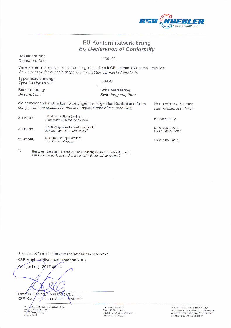
OSA,S
SchaltverstärkerSwitching amplifier
Tel.: +49 6263 B7-0Fax: +49 6263 87-99E-lvlail: [email protected]\M.ksr kueb er.com
Amtsgericht l\y'annheim HRB 714806Vorsltz des Aufsichtsrates: Dirk FellermannVorstand: Thomas Gerling (Vorsitzender)Gerlchisstand: Mosbach/Baden
die grundlegenden Schutzanforderungen der folgenden Richtlinien erfüllen. Harmonisierte Normen:comply with the essential protection requirements of the directives: Harmonized standards.
Gefährliche Stoffe (RoHS)H azardou s subsfances ( RoH S)
Elektromagnetische Verträglichkeit(1)E I e ctro m ag n eti c Co m p ati b i I ity'
1 )
Niederspann ungsrichtlinieLow Voltage Directive
Emission (Gruppe 1, Klasse A) und Störfestigkeit (industrieller Bereich)Emission (group 1, c/ass A) and immunity (industrial application).
Unterzeichnet für und im Namen von I Signed for and on behalf of
KSR Ku hnik AG
KSR Kue
EBLER Niveau-Messtechnik AG
EN 50581 :20'12
EN 61326-1 :20'13EN 61326-2-3:2013
EN 61010-1:2010
'-1417
Deutschland
iK AG
R,(SRXKAEELER
vä A div60n ol lhe WIKA croup
E U -Konfo rm itätserkläru n gEU Declaration of Conformity
Wir erklären in alleiniger Verantwortung, dass die mit CE gekennzeichneten ProdukteWe declare under our sole responsibility that the CE marked products
Typenbezeich nung:Type Designation:
Beschreibung:Description:
Dokument Nr.:Document No.:
2011t65tEU
20141301EU
2014t35tEU
2014t34tEU
Gefährliche Stoffe (RoHS)H azardou s substances ( RoH S)
Elektromag netische Verträglichkeit(1'E t e ct ro m a g n eti c Co m p ati bii tl 1'
N iederspan n ungs richtlin ieLow Voltage Directive
Explosionsschutz (ATEX)(2x3)Ex pl o si o n p rotecti o n (AT Eyyztrst
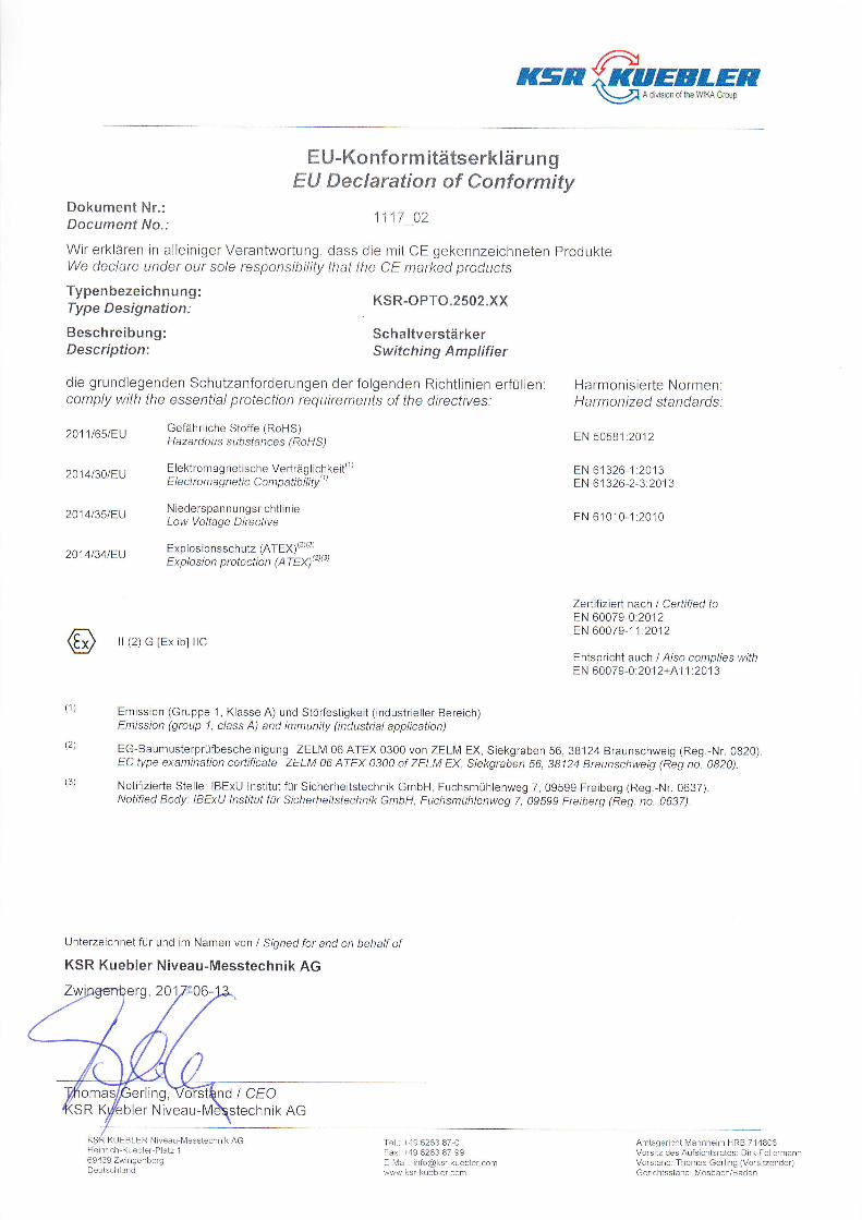
1117 02
KSR-OPTO.2502.XX
SchaltverstärkerSwitching Amplifier
Tel.: +49 6263 B7-0Fax: +49 6263 87-99E-Mai : [email protected] ksr-kuebler com
EN 50581:2012
EN 61326-1 :2013EN 61326-2-3:20'13
EN 61010-1:2010
Zertfiiziert nach I Certified toEN 60079-0:2012EN 60079-1 1:20'12
Entspricht auch / A/so complies withEN 60079-0:2012+41 1 :2013
die grundlegenden Schutzanforderungen der folgenden Richtlinien erfüllen: Harmonisierte Normen:comply with the essenfia/ protection requirements of the directives: Harmonized standards:
(3)
ll (2) G [Ex ib] llC
(2)
Unterzeichnet für und im Namen von I Signed for and on behalf ot
KSR Kuebler Niveau-Messtechnik AG
rling, I CEObler Nivea
KU EBLER Niveau-l\,4esstechnik AGich-Kuebler-Platz 1
69439 ZwingenbergDeutsch and
Emission (Gruppe 1, Klasse A) und Störfestigkeit (industrieller Bereich)Emission (group 1, c/ass Ä) and immunity (industrial application)
EG-Baumusterprüfbescheinigung ZELM 06 ATEX 0300 von ZELM EX, Siekgraben 56,38124 Braunschweig (Reg.-Nr. 0820)EC type examination ceftificate ZELM 06 ATEX 0300 of ZELM EX, Siekgraben 56, 38124 Braunschweig (Reg.no. 0820).
Notifizierte Stelle: IBExU Institut für Sicherheitstechnik GmbH, Fuchsmühlenweg 7, 09599 Freiberg (Reg -Nr. 0637).Notified Body: IBExU lnstitut für Sicherheitstechnik GmbH, Fuchsmühlenweg 7, 09599 Freiberg (Reg. no. 0637).
06-20
Amtsgericht Mannheim HRB 7'14806Vorsltz des Aufsichtsrates: Dirk FellermannVorstand: Thomas Gerling (Vorsltzender)Gerichtsstand: Mosbach/Baden
hnik AG

KSR KUEBLER Niveau-Messtechnik GmbH, Heinrich-Kuebler-Platz 1, 69439 Zwingenberg am Neckar, Telefon: 0 62 63/87-0, Telefax: 0 62 63/87-99
64

KSR KUEBLER Niveau-Messtechnik GmbH, Heinrich-Kuebler-Platz 1, 69439 Zwingenberg am Neckar, Telefon: 0 62 63/87-0, Telefax: 0 62 63/87-99
65

KSR KUEBLER Niveau-Messtechnik GmbH, Heinrich-Kuebler-Platz 1, 69439 Zwingenberg am Neckar, Telefon: 0 62 63/87-0, Telefax: 0 62 63/87-99
66

KSR KUEBLER Niveau-Messtechnik GmbH, Heinrich-Kuebler-Platz 1, 69439 Zwingenberg am Neckar, Telefon: 0 62 63/87-0, Telefax: 0 62 63/87-99
67

KSR KUEBLER Niveau-Messtechnik GmbH, Heinrich-Kuebler-Platz 1, 69439 Zwingenberg am Neckar, Telefon: 0 62 63/87-0, Telefax: 0 62 63/87-99
68
KSR KUEBLER Niveau-Messtechnik GmbH Heinrich-Kuebler-Platz 1 69439 Zwingenberg am Neckar Phone: 0 62 63/87-0 Fax: 0 62 63/87-99 E-Mail: [email protected] Internet: www.ksr-kuebler.com