sas/gis 9.3: spatial data and procedure guide · • manage data using tools for data entry,...
TRANSCRIPT
SAS/GIS® 9.3: Spatial Dataand Procedure Guide
SAS® Documentation

The correct bibliographic citation for this manual is as follows: SAS Institute Inc. 2011. SAS/GIS® 9.3: Spatial Data and Procedure Guide. Cary,NC: SAS Institute Inc.
SAS/GIS® 9.3: Spatial Data and Procedure Guide
Copyright © 2011, SAS Institute Inc., Cary, NC, USA
All rights reserved. Produced in the United States of America.
For a hardcopy book:No part of this publication may be reproduced, stored in a retrieval system, or transmitted, in any form or by any means,electronic, mechanical, photocopying, or otherwise, without the prior written permission of the publisher, SAS Institute Inc.
For a Web download or e-book:Your use of this publication shall be governed by the terms established by the vendor at the time you acquire thispublication.
The scanning, uploading, and distribution of this book via the Internet or any other means without the permission of the publisher is illegal andpunishable by law. Please purchase only authorized electronic editions and do not participate in or encourage electronic piracy of copyrightedmaterials. Your support of others' rights is appreciated.
U.S. Government Restricted Rights Notice: Use, duplication, or disclosure of this software and related documentation by the U.S. government issubject to the Agreement with SAS Institute and the restrictions set forth in FAR 52.227–19 Commercial Computer Software-Restricted Rights(June 1987).
SAS Institute Inc., SAS Campus Drive, Cary, North Carolina 27513.
1st electronic book, July 2011
SAS® Publishing provides a complete selection of books and electronic products to help customers use SAS software to its fullest potential. Formore information about our e-books, e-learning products, CDs, and hard-copy books, visit the SAS Publishing Web site atsupport.sas.com/publishing or call 1-800-727-3228.
SAS® and all other SAS Institute Inc. product or service names are registered trademarks or trademarks of SAS Institute Inc. in the USA and othercountries. ® indicates USA registration.
Other brand and product names are registered trademarks or trademarks of their respective companies.
Contents
Recommended Reading . . . . . . . . . . . . . . . . . . . . . . . . . . . . . . . . . . . . . . . . . . . . . . . . . . . v
Chapter 1 • Overview of SAS/GIS Software . . . . . . . . . . . . . . . . . . . . . . . . . . . . . . . . . . . . . . . . . . 1Introduction to Geographic Information Systems . . . . . . . . . . . . . . . . . . . . . . . . . . . . . . 1Features of SAS Software . . . . . . . . . . . . . . . . . . . . . . . . . . . . . . . . . . . . . . . . . . . . . . . . . 2Data in SAS/GIS Applications . . . . . . . . . . . . . . . . . . . . . . . . . . . . . . . . . . . . . . . . . . . . . 2Using the SAS/GIS Interface . . . . . . . . . . . . . . . . . . . . . . . . . . . . . . . . . . . . . . . . . . . . . . 8Accessing the SAS/GIS Tutorial . . . . . . . . . . . . . . . . . . . . . . . . . . . . . . . . . . . . . . . . . . . 9
Chapter 2 • Preparing Spatial Data . . . . . . . . . . . . . . . . . . . . . . . . . . . . . . . . . . . . . . . . . . . . . . . . 11Assessing Your Spatial Data Needs . . . . . . . . . . . . . . . . . . . . . . . . . . . . . . . . . . . . . . . . 11Examples of Common Spatial Data Tasks . . . . . . . . . . . . . . . . . . . . . . . . . . . . . . . . . . . 13Changing the Default Characteristics of a Map . . . . . . . . . . . . . . . . . . . . . . . . . . . . . . . 15Linking the Attribute Data to the Spatial Data . . . . . . . . . . . . . . . . . . . . . . . . . . . . . . . . 19Saving the Map Characteristics . . . . . . . . . . . . . . . . . . . . . . . . . . . . . . . . . . . . . . . . . . . 20
Chapter 3 • Importing Spatial Data . . . . . . . . . . . . . . . . . . . . . . . . . . . . . . . . . . . . . . . . . . . . . . . . 21Overview of Importing Spatial Data . . . . . . . . . . . . . . . . . . . . . . . . . . . . . . . . . . . . . . . . 21The GIS Spatial Data Importing Window . . . . . . . . . . . . . . . . . . . . . . . . . . . . . . . . . . . 22Common Importing Procedures . . . . . . . . . . . . . . . . . . . . . . . . . . . . . . . . . . . . . . . . . . . 25Importing ArcInfo Interchange Data . . . . . . . . . . . . . . . . . . . . . . . . . . . . . . . . . . . . . . . 26Importing DLG Data . . . . . . . . . . . . . . . . . . . . . . . . . . . . . . . . . . . . . . . . . . . . . . . . . . . . 27Importing DXF Data . . . . . . . . . . . . . . . . . . . . . . . . . . . . . . . . . . . . . . . . . . . . . . . . . . . . 28Importing Dynamap Data . . . . . . . . . . . . . . . . . . . . . . . . . . . . . . . . . . . . . . . . . . . . . . . . 28Importing MapInfo Data . . . . . . . . . . . . . . . . . . . . . . . . . . . . . . . . . . . . . . . . . . . . . . . . . 30Importing SAS/GRAPH Map Data Sets . . . . . . . . . . . . . . . . . . . . . . . . . . . . . . . . . . . . . 30Importing TIGER Data . . . . . . . . . . . . . . . . . . . . . . . . . . . . . . . . . . . . . . . . . . . . . . . . . . 31Importing Generic Spatial Data . . . . . . . . . . . . . . . . . . . . . . . . . . . . . . . . . . . . . . . . . . . 33Defining Composites in Imported Data . . . . . . . . . . . . . . . . . . . . . . . . . . . . . . . . . . . . . 36Defining Layers in Imported Data . . . . . . . . . . . . . . . . . . . . . . . . . . . . . . . . . . . . . . . . . 37The SASHELP.GISIMP Data Set . . . . . . . . . . . . . . . . . . . . . . . . . . . . . . . . . . . . . . . . . . 39
Chapter 4 • Batch Importing . . . . . . . . . . . . . . . . . . . . . . . . . . . . . . . . . . . . . . . . . . . . . . . . . . . . . 41Overview of Batch Importing . . . . . . . . . . . . . . . . . . . . . . . . . . . . . . . . . . . . . . . . . . . . . 41The Batch Import Process . . . . . . . . . . . . . . . . . . . . . . . . . . . . . . . . . . . . . . . . . . . . . . . . 42Examples of Batch Importing . . . . . . . . . . . . . . . . . . . . . . . . . . . . . . . . . . . . . . . . . . . . . 46File Reference Table for Batch Importing . . . . . . . . . . . . . . . . . . . . . . . . . . . . . . . . . . . 49Hints and Tips for Batch Importing . . . . . . . . . . . . . . . . . . . . . . . . . . . . . . . . . . . . . . . . 50
Chapter 5 • Working with Spatial Data . . . . . . . . . . . . . . . . . . . . . . . . . . . . . . . . . . . . . . . . . . . . . 53SAS/GIS Data Sets . . . . . . . . . . . . . . . . . . . . . . . . . . . . . . . . . . . . . . . . . . . . . . . . . . . . . 53Data Set and Catalog Entry Interactions . . . . . . . . . . . . . . . . . . . . . . . . . . . . . . . . . . . . . 61Merging Spatial Data with the MERGE= Argument . . . . . . . . . . . . . . . . . . . . . . . . . . . 66Sample SAS/GIS Spatial Database . . . . . . . . . . . . . . . . . . . . . . . . . . . . . . . . . . . . . . . . . 67Hints and Tips for Working with Spatial Data . . . . . . . . . . . . . . . . . . . . . . . . . . . . . . . . 67
Chapter 6 • Batch Geocoding . . . . . . . . . . . . . . . . . . . . . . . . . . . . . . . . . . . . . . . . . . . . . . . . . . . . 69Overview of Batch Geocoding . . . . . . . . . . . . . . . . . . . . . . . . . . . . . . . . . . . . . . . . . . . . 69Addresses in Spatial Data . . . . . . . . . . . . . . . . . . . . . . . . . . . . . . . . . . . . . . . . . . . . . . . . 70
Using Batch Geocoding . . . . . . . . . . . . . . . . . . . . . . . . . . . . . . . . . . . . . . . . . . . . . . . . . 71How Batch Geocoding Works . . . . . . . . . . . . . . . . . . . . . . . . . . . . . . . . . . . . . . . . . . . . 71%GCBATCH Macro Statement . . . . . . . . . . . . . . . . . . . . . . . . . . . . . . . . . . . . . . . . . . . 75Batch Geocoding Example . . . . . . . . . . . . . . . . . . . . . . . . . . . . . . . . . . . . . . . . . . . . . . . 77Hints and Tips for Batch Geocoding . . . . . . . . . . . . . . . . . . . . . . . . . . . . . . . . . . . . . . . 80
Chapter 7 • The GIS Procedure . . . . . . . . . . . . . . . . . . . . . . . . . . . . . . . . . . . . . . . . . . . . . . . . . . . 83Overview: GIS Procedure . . . . . . . . . . . . . . . . . . . . . . . . . . . . . . . . . . . . . . . . . . . . . . . . 83Concepts: GIS Procedure . . . . . . . . . . . . . . . . . . . . . . . . . . . . . . . . . . . . . . . . . . . . . . . . 84Syntax: The GIS Procedure . . . . . . . . . . . . . . . . . . . . . . . . . . . . . . . . . . . . . . . . . . . . . . 86
Appendix 1 • Sample Map Data Sets . . . . . . . . . . . . . . . . . . . . . . . . . . . . . . . . . . . . . . . . . . . . . . 161Map and Data Sets Supplied with SAS/GIS Software . . . . . . . . . . . . . . . . . . . . . . . . . 161Maps in the USA Catalog . . . . . . . . . . . . . . . . . . . . . . . . . . . . . . . . . . . . . . . . . . . . . . . 161Maps in the NC Catalog . . . . . . . . . . . . . . . . . . . . . . . . . . . . . . . . . . . . . . . . . . . . . . . . 163Maps in the WAKE Catalog . . . . . . . . . . . . . . . . . . . . . . . . . . . . . . . . . . . . . . . . . . . . . 164Copying and Modifying SAS/GIS Maps in the MAPS Library . . . . . . . . . . . . . . . . . . 165Maps Produced by the SAS/GIS Tutorial . . . . . . . . . . . . . . . . . . . . . . . . . . . . . . . . . . . 166
Appendix 2 • Spatial Database Details . . . . . . . . . . . . . . . . . . . . . . . . . . . . . . . . . . . . . . . . . . . . 169The SAS/GIS Data Model . . . . . . . . . . . . . . . . . . . . . . . . . . . . . . . . . . . . . . . . . . . . . . 169SAS/GIS Spatial Database Structure . . . . . . . . . . . . . . . . . . . . . . . . . . . . . . . . . . . . . . 172Composites . . . . . . . . . . . . . . . . . . . . . . . . . . . . . . . . . . . . . . . . . . . . . . . . . . . . . . . . . . 180
Appendix 3 • Calculating Chain Rank . . . . . . . . . . . . . . . . . . . . . . . . . . . . . . . . . . . . . . . . . . . . . 181RANK Value Equation . . . . . . . . . . . . . . . . . . . . . . . . . . . . . . . . . . . . . . . . . . . . . . . . . 181Chain Rank Calculation Examples . . . . . . . . . . . . . . . . . . . . . . . . . . . . . . . . . . . . . . . . 185
Glossary . . . . . . . . . . . . . . . . . . . . . . . . . . . . . . . . . . . . . . . . . . . . . . . . . . . . . 189Index . . . . . . . . . . . . . . . . . . . . . . . . . . . . . . . . . . . . . . . . . . . . . . . . . . . . . . . . 195
iv Contents
Recommended Reading
• SAS/ACCESS for Relational Databases: Reference
• SAS/FSP: Procedures Guide
• SAS/GRAPH: Reference
• SAS Language Reference: Concepts
• SAS Statements: Reference
• SAS Data Set Options: Reference
• SAS System Options: Reference
• Base SAS Procedures Guide
• SAS Companion that is specific to your operating environment
For a complete list of SAS publications, go to support.sas.com/bookstore. If you havequestions about which titles you need, please contact a SAS Publishing SalesRepresentative:
SAS Publishing SalesSAS Campus DriveCary, NC 27513-2414Phone: 1-800-727-3228Fax: 1-919-677-8166E-mail: [email protected] address: support.sas.com/bookstore
v

vi Recommended Reading
Chapter 1
Overview of SAS/GIS Software
Introduction to Geographic Information Systems . . . . . . . . . . . . . . . . . . . . . . . . . . . . 1
Features of SAS Software . . . . . . . . . . . . . . . . . . . . . . . . . . . . . . . . . . . . . . . . . . . . . . . 2
Data in SAS/GIS Applications . . . . . . . . . . . . . . . . . . . . . . . . . . . . . . . . . . . . . . . . . . . . 2SAS/GIS Data Types . . . . . . . . . . . . . . . . . . . . . . . . . . . . . . . . . . . . . . . . . . . . . . . . . 2Spatial Data . . . . . . . . . . . . . . . . . . . . . . . . . . . . . . . . . . . . . . . . . . . . . . . . . . . . . . . . . 3Attribute Data . . . . . . . . . . . . . . . . . . . . . . . . . . . . . . . . . . . . . . . . . . . . . . . . . . . . . . . 5Designing a SAS/GIS Spatial Database . . . . . . . . . . . . . . . . . . . . . . . . . . . . . . . . . . . 6
Using the SAS/GIS Interface . . . . . . . . . . . . . . . . . . . . . . . . . . . . . . . . . . . . . . . . . . . . . 8Starting SAS/GIS Software . . . . . . . . . . . . . . . . . . . . . . . . . . . . . . . . . . . . . . . . . . . . 8Using Dialog Box Elements . . . . . . . . . . . . . . . . . . . . . . . . . . . . . . . . . . . . . . . . . . . . 8Selecting Maps and SAS Data Sets . . . . . . . . . . . . . . . . . . . . . . . . . . . . . . . . . . . . . . 9
Accessing the SAS/GIS Tutorial . . . . . . . . . . . . . . . . . . . . . . . . . . . . . . . . . . . . . . . . . . 9
Introduction to Geographic Information SystemsSAS/GIS software provides an interactive geographic information system within SAS. Ageographic information system (GIS) is a tool for organizing and analyzing data that canbe referenced spatially, that is, data that can be tied to physical locations. Many types ofdata have a spatial aspect, including demographics, marketing surveys, customeraddresses, and epidemiological studies. A GIS helps you analyze your data in the contextof location.
For example, if you need to evaluate population data for census tracts, you could viewthe information in tabular format. However, consider how much easier and moreeffective it is to view the demographic information in the context of the geography of thetracts as shown in the following figure. When viewing information that has a spatialcomponent, you might find it easier to recognize relationships and trends in your data ifyou view the information in a spatial context.
1
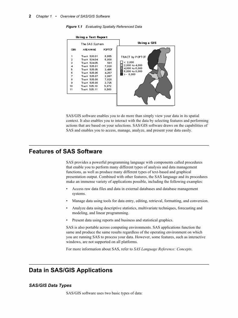
Figure 1.1 Evaluating Spatially Referenced Data
SAS/GIS software enables you to do more than simply view your data in its spatialcontext. It also enables you to interact with the data by selecting features and performingactions that are based on your selections. SAS/GIS software draws on the capabilities ofSAS and enables you to access, manage, analyze, and present your data easily.
Features of SAS SoftwareSAS provides a powerful programming language with components called proceduresthat enable you to perform many different types of analysis and data managementfunctions, as well as produce many different types of text-based and graphicalpresentation output. Combined with other features, the SAS language and its proceduresmake an immense variety of applications possible, including the following examples:
• Access raw data files and data in external databases and database managementsystems.
• Manage data using tools for data entry, editing, retrieval, formatting, and conversion.
• Analyze data using descriptive statistics, multivariate techniques, forecasting andmodeling, and linear programming.
• Present data using reports and business and statistical graphics.
SAS is also portable across computing environments. SAS applications function thesame and produce the same results regardless of the operating environment on whichyou are running SAS to process your data. However, some features, such as interactivewindows, are not supported on all platforms.
For more information about SAS, refer to SAS Language Reference: Concepts.
Data in SAS/GIS Applications
SAS/GIS Data TypesSAS/GIS software uses two basic types of data:
2 Chapter 1 • Overview of SAS/GIS Software
spatial datacontains the coordinates and identifying information that describes the map featuressuch as streets, rivers, and railroads.
attribute datais the information that you want to use for analysis or presentation. This informationmust be spatial in nature. Examples of information that is spatial in nature becausethe information applies to a specific geographic feature include the following:
• sales figures for each of your store locations
• population data for each county
• total income for each household in a region
For example, the U.S. Census Bureau distributes both types of data:
TIGER Line filescontain spatial information that you can use to build maps.
Summary Tape filescontain population and other demographic information that you can link to the mapfeatures.
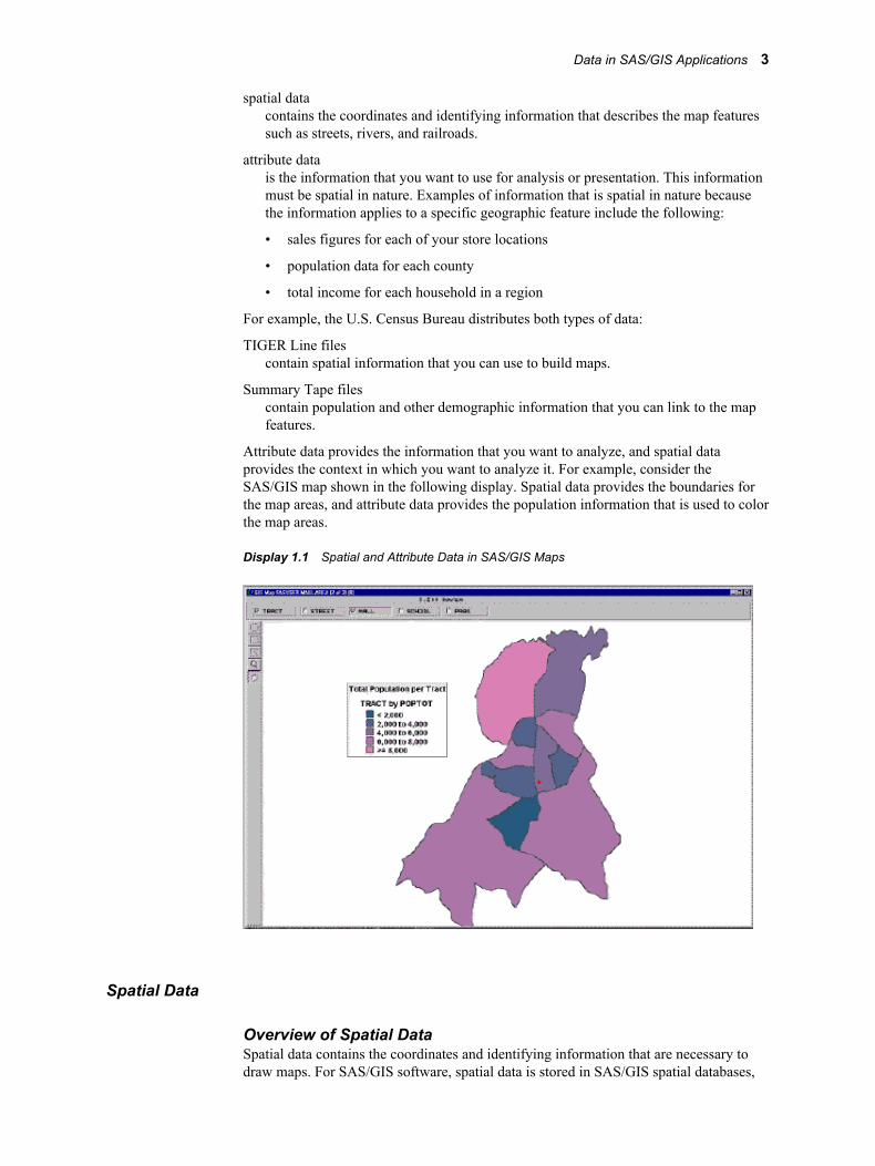
Attribute data provides the information that you want to analyze, and spatial dataprovides the context in which you want to analyze it. For example, consider theSAS/GIS map shown in the following display. Spatial data provides the boundaries forthe map areas, and attribute data provides the population information that is used to colorthe map areas.
Display 1.1 Spatial and Attribute Data in SAS/GIS Maps
Spatial Data
Overview of Spatial DataSpatial data contains the coordinates and identifying information that are necessary todraw maps. For SAS/GIS software, spatial data is stored in SAS/GIS spatial databases,
Data in SAS/GIS Applications 3
which consist of collections of SAS data sets and SAS catalog entries. The primarymethod for creating a SAS/GIS spatial database is through the SAS/GIS Import facility,either in batch or in interactive mode. You can also use the GIS procedure to create,modify, and manage the catalog entries in a spatial database.
Spatial Data LayersFeatures in the spatial data are organized into layers. A layer is a collection of all thefeatures in the map that share some common characteristic. The various physical aspectsof the map—political boundaries, roads, railroads, waterways, and so on—are assignedto layers according to their common spatial data values. Some features can appear inmultiple layers. For example, a street can also be a ZIP code boundary and a cityboundary line. The street could appear in three layers: one containing the streets, onecontaining the ZIP code boundaries, and one containing the city boundaries.
Three types of layers can be represented in SAS/GIS maps: points, lines, and areas. Forexample,
• the collection of all the points in a map that represent park locations can be organizedinto a point layer for parks
• the collection of all the lines in a map that represent streets can be organized into aline layer for streets
• the collection of all the areas that represent census tracts can be organized into anarea layer for tracts
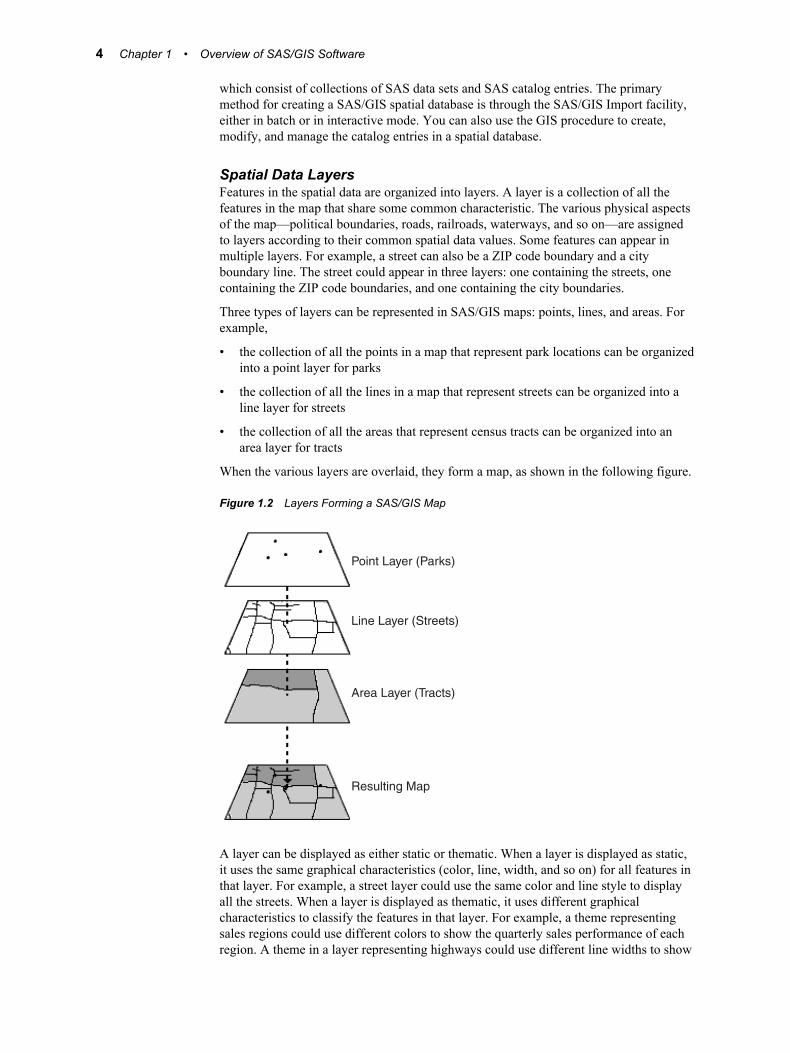
When the various layers are overlaid, they form a map, as shown in the following figure.
Figure 1.2 Layers Forming a SAS/GIS Map
Point Layer (Parks)
Line Layer (Streets)
Area Layer (Tracts)
Resulting Map
A layer can be displayed as either static or thematic. When a layer is displayed as static,it uses the same graphical characteristics (color, line, width, and so on) for all features inthat layer. For example, a street layer could use the same color and line style to displayall the streets. When a layer is displayed as thematic, it uses different graphicalcharacteristics to classify the features in that layer. For example, a theme representingsales regions could use different colors to show the quarterly sales performance of eachregion. A theme in a layer representing highways could use different line widths to show
4 Chapter 1 • Overview of SAS/GIS Software
the classes of roads. A layer can have multiple themes stored in it, and you can easilychange which theme is currently displayed.
Spatial Data CoveragesIn SAS/GIS software, maps display only the portion of the spatial data that falls within agiven coverage. A coverage defines a subset of the spatial data that is available to a map.The coverage can include all the spatial data in the database, or only selected portions.For example, a spatial database might contain geographic data for an entire country, buta coverage might restrict the portion that is available for a given map to only one region.You can define more than one coverage for each spatial database, although a map usesonly one coverage at a time.
Spatial Data CompositesMost operations in SAS/GIS software use composites of spatial data variables ratherthan the actual spatial data variables themselves. Composites identify the relationshipsand purpose of the variables in the spatial data.
For example, if the spatial data has the variables STATEL and STATER that contain thestate ID codes for the left and right sides of each feature, then the spatial database coulddefine a composite named STATE that identifies the relationship between thesevariables and specifies that they delineate state areas in the map. You would use theSTATE composite, rather than the actual STATEL and STATER variables, to link stateareas in the map to attribute data for the corresponding state.
See Appendix 2, “Spatial Database Details,” on page 169 for more information aboutthe structure of SAS/GIS spatial databases.
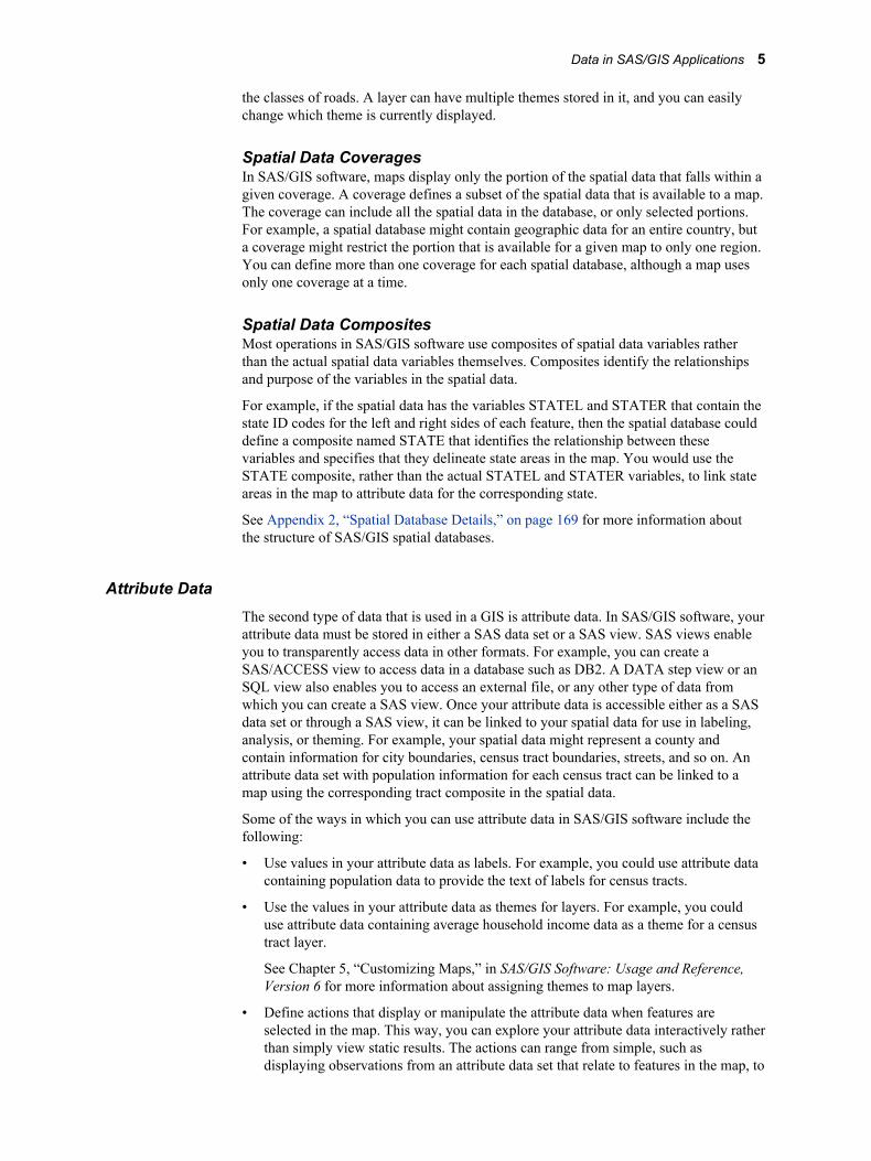
Attribute DataThe second type of data that is used in a GIS is attribute data. In SAS/GIS software, yourattribute data must be stored in either a SAS data set or a SAS view. SAS views enableyou to transparently access data in other formats. For example, you can create aSAS/ACCESS view to access data in a database such as DB2. A DATA step view or anSQL view also enables you to access an external file, or any other type of data fromwhich you can create a SAS view. Once your attribute data is accessible either as a SASdata set or through a SAS view, it can be linked to your spatial data for use in labeling,analysis, or theming. For example, your spatial data might represent a county andcontain information for city boundaries, census tract boundaries, streets, and so on. Anattribute data set with population information for each census tract can be linked to amap using the corresponding tract composite in the spatial data.
Some of the ways in which you can use attribute data in SAS/GIS software include thefollowing:
• Use values in your attribute data as labels. For example, you could use attribute datacontaining population data to provide the text of labels for census tracts.
• Use the values in your attribute data as themes for layers. For example, you coulduse attribute data containing average household income data as a theme for a censustract layer.
See Chapter 5, “Customizing Maps,” in SAS/GIS Software: Usage and Reference,Version 6 for more information about assigning themes to map layers.
• Define actions that display or manipulate the attribute data when features areselected in the map. This way, you can explore your attribute data interactively ratherthan simply view static results. The actions can range from simple, such asdisplaying observations from an attribute data set that relate to features in the map, to
Data in SAS/GIS Applications 5
complex, such as submitting a procedure from SAS/STAT software to perform astatistical analysis.
You can define the following actions for your attribute data:
• Display observations from attribute data sets that relate to selected map features.
• Open additional maps that relate to selected map features.
• Display images that relate to selected map features.
• Interactively subset attribute data sets according to a subset of selected map features.
• Submit SAS programs.
• Issue SAS commands.
• Issue host commands.
• Display and edit information for the selected map features.
• Organize area features into groups that are based on your attribute data.
See Chapter 4, “Performing Actions for Selected Map Features” in SAS/GIS Software:Usage and Reference, Version 6 for more information about defining and performingactions.
Designing a SAS/GIS Spatial Database
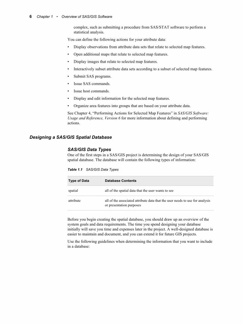
SAS/GIS Data TypesOne of the first steps in a SAS/GIS project is determining the design of your SAS/GISspatial database. The database will contain the following types of information:
Table 1.1 SAS/GIS Data Types
Type of Data Database Contents
spatial all of the spatial data that the user wants to see
attribute all of the associated attribute data that the user needs to use for analysisor presentation purposes
Before you begin creating the spatial database, you should draw up an overview of thesystem goals and data requirements. The time you spend designing your databaseinitially will save you time and expenses later in the project. A well-designed database iseasier to maintain and document, and you can extend it for future GIS projects.
Use the following guidelines when determining the information that you want to includein a database:
6 Chapter 1 • Overview of SAS/GIS Software

Table 1.2 SAS/GIS Spatial Database Guidelines
If you want to determine... Then
project objective 1. Identify the initial objective of the project and itsultimate goal.
2. Consider any requirements that might have beenimposed on it.
3. Determine the feasibility of initial implementationand, as best as possible, the impact of any futuredemands.
attribute data 1. Identify the attribute data that is necessary to illustratethe project objectives.
2. Determine whether you have this data or can obtain it.
spatial data 1. Identify the spatial features that you need to link withyour attribute data, for example, states, cities, rivers,roads, railroads, airports, and so on.
2. Determine whether you have this data or can obtain it.
Once you have determined a preliminary list of the data that you will need, use theadditional factors in the following sections to help you evaluate and refine your list.
Enable Linking between Spatial Features and Attribute DataTo use attribute data for map actions, themes, or labeling, the attribute data set mustcontain the same identification information as the spatial feature that it describes so thatyou can link between them. For example, if your attribute data has Sales Revenue forstores, and Store ID Numbers, you probably want to include the actual location inlongitude and latitude for each Store ID Number on your spatial data list. You can thenplace a marker at the store location and also visualize and analyze the correspondingattribute data for each store.
Use No More Details than You NeedUse only the data that you need for your project. For example, if you have storelocations that request the customer ZIP code at the cash register, you should not assumethat you need ZIP code boundaries on your map. ZIP code boundaries might be far toosmall for your purposes if you have stores nationwide. You might decide instead that thethree-digit ZIP code boundaries provide fewer, yet more appropriately sized, areas foryour analysis. You can summarize your attribute data to the three-digit ZIP code leveland use it for your analysis, reducing both the amount of spatial data and attribute datathat you need. As long as it is appropriate for your analysis, decreasing the amount ofrequired spatial and attribute data reduces storage space and improves performance.Reducing the level of detail in the spatial data also saves money if you have to purchasethe data.
Ensure a Common Level of Spatial and Attribute DataIf you plan to summarize your attribute data to a matching level of your spatial data,make sure that the two types of data have a common level that you can use. For example,ZIP code boundaries can cross not only county boundaries, but also state boundaries, sothere is usually not a one-to-one correspondence between ZIP codes and states orcounties. If the only information that ties your attribute data to your spatial data is ZIP
Data in SAS/GIS Applications 7
codes, you will have difficulties using your ZIP code level attribute data if you includeonly state or county boundaries in your spatial data.
For specific, smaller areas of the country, a one-to-one correspondence might exist thatwill enable you to summarize your attribute data to a higher level. However, ZIP codescan change frequently, and this correspondence might be lost. Also, because ZIP codeschange, you must be able to account for these changes when performing a historicalanalysis. For example, if you are comparing sales in a specific ZIP code area over a ten-year period, make sure that the area remained constant during that period. The same istrue for other spatial data.
Using the SAS/GIS Interface
Starting SAS/GIS SoftwareUse the following steps to start a SAS/GIS software session:
1. Open a SAS session.
2. From the SAS menu bar, select Solutions ð Analysis ð Geographic InformationSystem
Or type GIS in the SAS Command Box or on any SAS command line.
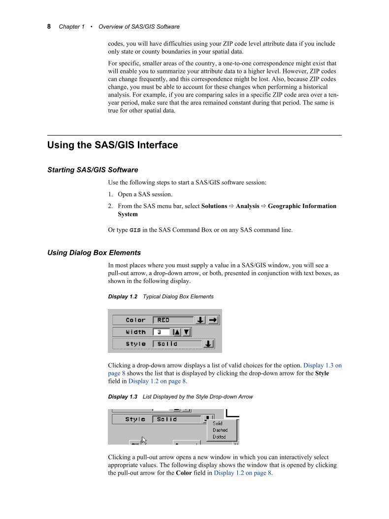
Using Dialog Box ElementsIn most places where you must supply a value in a SAS/GIS window, you will see apull-out arrow, a drop-down arrow, or both, presented in conjunction with text boxes, asshown in the following display.
Display 1.2 Typical Dialog Box Elements
Clicking a drop-down arrow displays a list of valid choices for the option. Display 1.3 onpage 8 shows the list that is displayed by clicking the drop-down arrow for the Stylefield in Display 1.2 on page 8.
Display 1.3 List Displayed by the Style Drop-down Arrow
Clicking a pull-out arrow opens a new window in which you can interactively selectappropriate values. The following display shows the window that is opened by clickingthe pull-out arrow for the Color field in Display 1.2 on page 8.
8 Chapter 1 • Overview of SAS/GIS Software
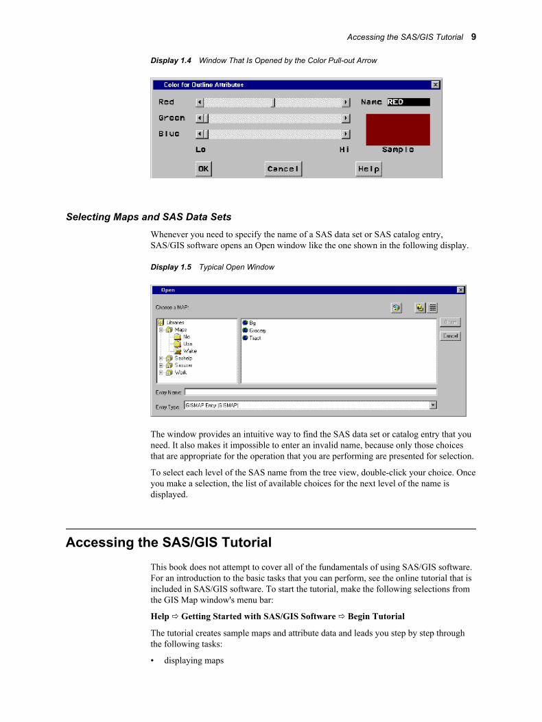
Display 1.4 Window That Is Opened by the Color Pull-out Arrow
Selecting Maps and SAS Data SetsWhenever you need to specify the name of a SAS data set or SAS catalog entry,SAS/GIS software opens an Open window like the one shown in the following display.
Display 1.5 Typical Open Window
The window provides an intuitive way to find the SAS data set or catalog entry that youneed. It also makes it impossible to enter an invalid name, because only those choicesthat are appropriate for the operation that you are performing are presented for selection.
To select each level of the SAS name from the tree view, double-click your choice. Onceyou make a selection, the list of available choices for the next level of the name isdisplayed.
Accessing the SAS/GIS TutorialThis book does not attempt to cover all of the fundamentals of using SAS/GIS software.For an introduction to the basic tasks that you can perform, see the online tutorial that isincluded in SAS/GIS software. To start the tutorial, make the following selections fromthe GIS Map window's menu bar:
Help ð Getting Started with SAS/GIS Software ð Begin Tutorial
The tutorial creates sample maps and attribute data and leads you step by step throughthe following tasks:
• displaying maps
Accessing the SAS/GIS Tutorial 9
• selecting the types of feedback that are provided about the displayed map
• using the zoom tool to zoom in on selected areas of the map
• using the pan tool to move the map within the window
• modifying, adding, and removing layers in the map
• using attribute data as a theme for a layer
• adding legends that explain how features are represented
• selecting features and using actions to explore the attribute data
• saving changes to the map
• geocoding addresses
• adding points to a map
After you have used the online tutorial to become familiar with the basics of usingSAS/GIS software, you can refer to SAS/GIS Software: Usage and Reference, Version 6for additional information about using SAS/GIS software and for detailed referenceinformation about the features of SAS/GIS software.
10 Chapter 1 • Overview of SAS/GIS Software

Chapter 2
Preparing Spatial Data
Assessing Your Spatial Data Needs . . . . . . . . . . . . . . . . . . . . . . . . . . . . . . . . . . . . . . . 11Assessing Your Attribute Data . . . . . . . . . . . . . . . . . . . . . . . . . . . . . . . . . . . . . . . . . 11Determining Your Spatial Data Requirements . . . . . . . . . . . . . . . . . . . . . . . . . . . . . 12Locating a Source of Spatial Data . . . . . . . . . . . . . . . . . . . . . . . . . . . . . . . . . . . . . . 12
Examples of Common Spatial Data Tasks . . . . . . . . . . . . . . . . . . . . . . . . . . . . . . . . . 13Importing Your Spatial Data . . . . . . . . . . . . . . . . . . . . . . . . . . . . . . . . . . . . . . . . . . 13
Changing the Default Characteristics of a Map . . . . . . . . . . . . . . . . . . . . . . . . . . . . 15Customizing Maps . . . . . . . . . . . . . . . . . . . . . . . . . . . . . . . . . . . . . . . . . . . . . . . . . . 15Selecting a Map Projection . . . . . . . . . . . . . . . . . . . . . . . . . . . . . . . . . . . . . . . . . . . . 16Selecting the Units System . . . . . . . . . . . . . . . . . . . . . . . . . . . . . . . . . . . . . . . . . . . . 17Selecting a Background Color . . . . . . . . . . . . . . . . . . . . . . . . . . . . . . . . . . . . . . . . . 17Choosing Which Layers Are Displayed . . . . . . . . . . . . . . . . . . . . . . . . . . . . . . . . . . 17Changing the Level of Detail . . . . . . . . . . . . . . . . . . . . . . . . . . . . . . . . . . . . . . . . . . 18
Linking the Attribute Data to the Spatial Data . . . . . . . . . . . . . . . . . . . . . . . . . . . . . 19
Saving the Map Characteristics . . . . . . . . . . . . . . . . . . . . . . . . . . . . . . . . . . . . . . . . . 20
Assessing Your Spatial Data NeedsYou use a geographic information system to explore data in the context of a map, so youmust have a map in order to use SAS/GIS software. Furthermore, the map must be in theform of spatial data that SAS/GIS software can use.
Assessing Your Attribute DataThe first step in deciding what spatial data you need is to assess the attribute data thatyou want to analyze. The attribute data must have a spatial component. That is, the datamust contain at least one variable with values that relate to location. Examples includecity, state, or country names or codes; street names; addresses; and so on. BecauseSAS/GIS software is part of SAS, the attribute data must also be in the form of a SASdata set or a SAS view. If needed, you can use any method that is available fortransforming your attribute data into a SAS data set or a SAS view. These methodsinclude, but are not limited to the following:
• using SAS programming statements or the SAS Import Wizard to read external filesinto SAS data sets
• using SAS/ACCESS software or the SQL procedure to create views to database files
11
• using SAS programming statements or the SQL procedure to create dynamic viewsto SAS data sets.
After you have ensured that your attribute data has a spatial component and is in aformat that SAS/GIS can read, you can move on to identifying and locating your spatialdata.
Determining Your Spatial Data RequirementsIn order to analyze attribute data with SAS/GIS software, you need spatial data thatcontains representations of features to at least the same level of detail as the locationinformation in your attribute data. For example, if your attribute data consists ofdemographic data for states, then your spatial data must provide at least state boundaries.If your attribute data consists of demographic data for smaller census tracts, then youneed spatial data that contains the corresponding census tract boundaries in order toexplore the demographic data with SAS/GIS software.
Locating a Source of Spatial DataYou might be able to purchase appropriate spatial data that has already been prepared inSAS/GIS format by a commercial data vendor. Contact SAS Technical Support forinformation about sources for spatial data in SAS/GIS format.
The other way to acquire spatial data for use with SAS/GIS software is to import it fromother formats. One readily accessible source of maps for importing is the map data setsthat are provided with SAS/GRAPH software. However, these maps provide onlypolitical boundaries and not other physical features such as rivers and major highways.Other sources for spatial data that you can import include the following:
• Governmental agencies. For example, SAS/GIS software can import spatial datafrom TIGER/Line files produced by the U.S. Census Bureau1 and from DLG filesproduced by the U.S. Geological Survey.
• Drawing and computer-aided design (CAD) packages. SAS/GIS software can importthe DXF interchange format that is supported by products from various vendors.
• Tele Atlas N.V. SAS/GIS can import the Dynamap files.
• MapInfo Corporation. SAS/GIS can import MapInfo MIF and MID files.
• ArcInfo software by ESRI. SAS/GIS can import uncompressed ArcInfo interchange(E00) files.
• User-created files. If no other source is available, you can use SAS programmingstatements to convert your spatial data into the required generic format, whichSAS/GIS software can then import.
Whatever the source, the spatial data must have at least one variable with values thatmatch values in the attribute data that you want to analyze. If necessary, you can useSAS to process either the attribute data or the spatial data. For example, if your attributedata contains state names and your spatial data contains state codes, you can use SASprogramming statements to generate corresponding codes for the names. Likewise, ifyour attribute data and spatial data both have codes to identify areas in the map, but thetwo sets of data use different codes for the same areas, then you can use SASprogramming statements to translate the coding schemes.
1 SAS/GIS can import 2006 Second Edition TIGER/Line files from the U.S. Census Bureau and earlier releases of the TIGER/Linespatial data format. Contact SAS Technical Support for the latest information about the availability of support for importing 2007TIGER/Line Shapefiles.
12 Chapter 2 • Preparing Spatial Data
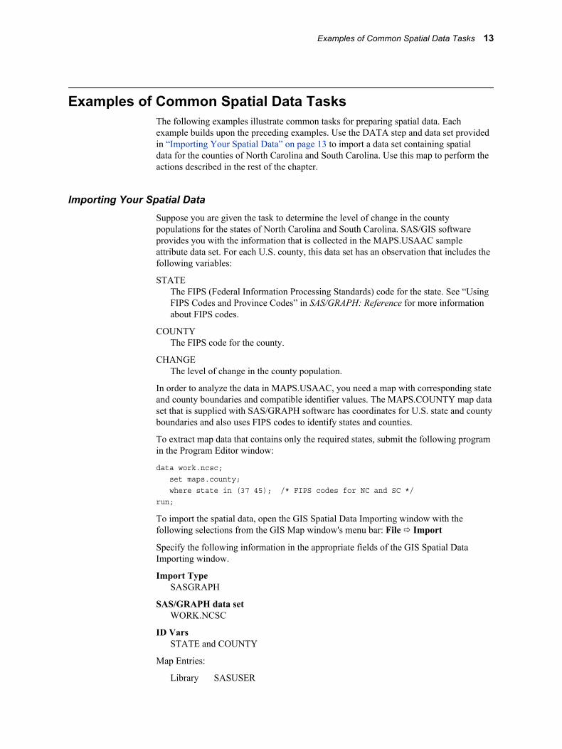
Examples of Common Spatial Data TasksThe following examples illustrate common tasks for preparing spatial data. Eachexample builds upon the preceding examples. Use the DATA step and data set providedin “Importing Your Spatial Data” on page 13 to import a data set containing spatialdata for the counties of North Carolina and South Carolina. Use this map to perform theactions described in the rest of the chapter.
Importing Your Spatial DataSuppose you are given the task to determine the level of change in the countypopulations for the states of North Carolina and South Carolina. SAS/GIS softwareprovides you with the information that is collected in the MAPS.USAAC sampleattribute data set. For each U.S. county, this data set has an observation that includes thefollowing variables:
STATEThe FIPS (Federal Information Processing Standards) code for the state. See “UsingFIPS Codes and Province Codes” in SAS/GRAPH: Reference for more informationabout FIPS codes.
COUNTYThe FIPS code for the county.
CHANGEThe level of change in the county population.
In order to analyze the data in MAPS.USAAC, you need a map with corresponding stateand county boundaries and compatible identifier values. The MAPS.COUNTY map dataset that is supplied with SAS/GRAPH software has coordinates for U.S. state and countyboundaries and also uses FIPS codes to identify states and counties.
To extract map data that contains only the required states, submit the following programin the Program Editor window:
data work.ncsc; set maps.county; where state in (37 45); /* FIPS codes for NC and SC */run;
To import the spatial data, open the GIS Spatial Data Importing window with thefollowing selections from the GIS Map window's menu bar: File ð Import
Specify the following information in the appropriate fields of the GIS Spatial DataImporting window.
Import TypeSASGRAPH
SAS/GRAPH data setWORK.NCSC
ID VarsSTATE and COUNTY
Map Entries:
Library SASUSER
Examples of Common Spatial Data Tasks 13
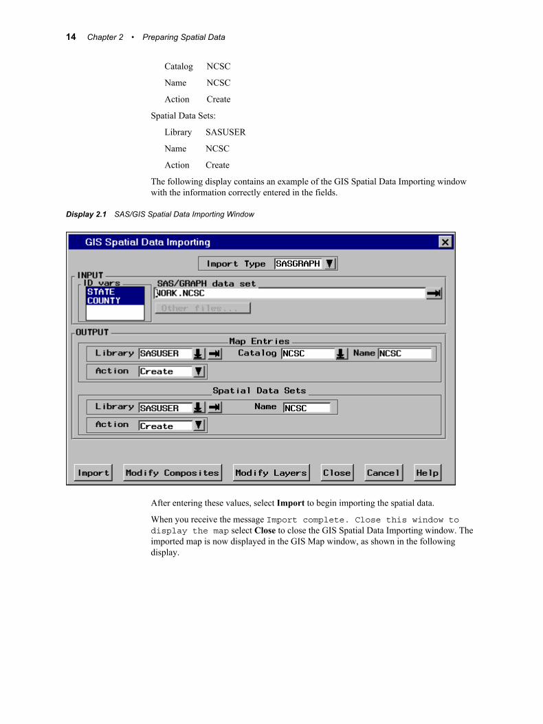
Catalog NCSC
Name NCSC
Action Create
Spatial Data Sets:
Library SASUSER
Name NCSC
Action Create
The following display contains an example of the GIS Spatial Data Importing windowwith the information correctly entered in the fields.
Display 2.1 SAS/GIS Spatial Data Importing Window
After entering these values, select Import to begin importing the spatial data.
When you receive the message Import complete. Close this window todisplay the map select Close to close the GIS Spatial Data Importing window. Theimported map is now displayed in the GIS Map window, as shown in the followingdisplay.
14 Chapter 2 • Preparing Spatial Data
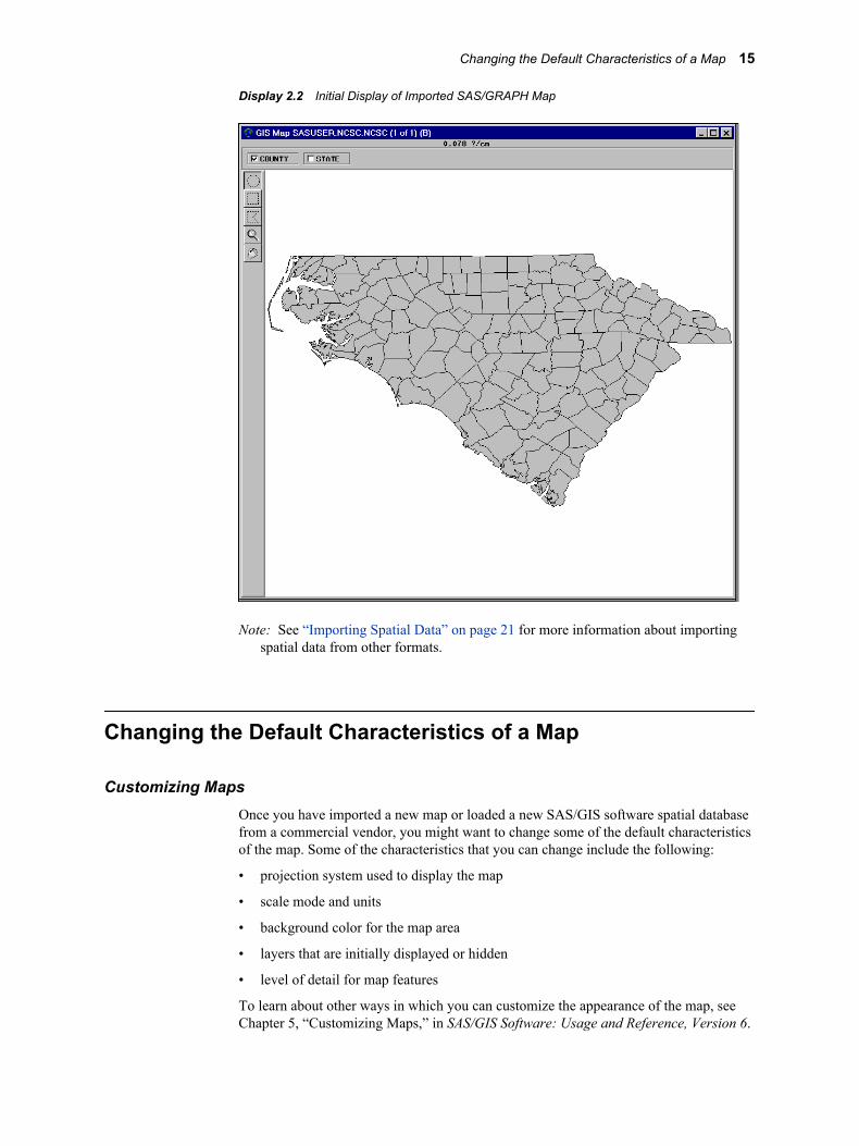
Display 2.2 Initial Display of Imported SAS/GRAPH Map
Note: See “Importing Spatial Data” on page 21 for more information about importingspatial data from other formats.
Changing the Default Characteristics of a Map
Customizing MapsOnce you have imported a new map or loaded a new SAS/GIS software spatial databasefrom a commercial vendor, you might want to change some of the default characteristicsof the map. Some of the characteristics that you can change include the following:
• projection system used to display the map
• scale mode and units
• background color for the map area
• layers that are initially displayed or hidden
• level of detail for map features
To learn about other ways in which you can customize the appearance of the map, seeChapter 5, “Customizing Maps,” in SAS/GIS Software: Usage and Reference, Version 6.
Changing the Default Characteristics of a Map 15
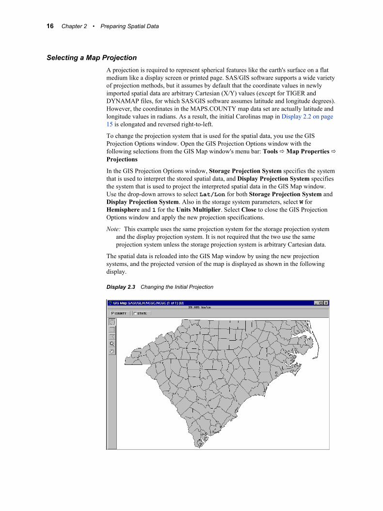
Selecting a Map ProjectionA projection is required to represent spherical features like the earth's surface on a flatmedium like a display screen or printed page. SAS/GIS software supports a wide varietyof projection methods, but it assumes by default that the coordinate values in newlyimported spatial data are arbitrary Cartesian (X/Y) values (except for TIGER andDYNAMAP files, for which SAS/GIS software assumes latitude and longitude degrees).However, the coordinates in the MAPS.COUNTY map data set are actually latitude andlongitude values in radians. As a result, the initial Carolinas map in Display 2.2 on page15 is elongated and reversed right-to-left.
To change the projection system that is used for the spatial data, you use the GISProjection Options window. Open the GIS Projection Options window with thefollowing selections from the GIS Map window's menu bar: Tools ð Map Properties ðProjections
In the GIS Projection Options window, Storage Projection System specifies the systemthat is used to interpret the stored spatial data, and Display Projection System specifiesthe system that is used to project the interpreted spatial data in the GIS Map window.Use the drop-down arrows to select Lat/Lon for both Storage Projection System andDisplay Projection System. Also in the storage system parameters, select W forHemisphere and 1 for the Units Multiplier. Select Close to close the GIS ProjectionOptions window and apply the new projection specifications.
Note: This example uses the same projection system for the storage projection systemand the display projection system. It is not required that the two use the sameprojection system unless the storage projection system is arbitrary Cartesian data.
The spatial data is reloaded into the GIS Map window by using the new projectionsystems, and the projected version of the map is displayed as shown in the followingdisplay.
Display 2.3 Changing the Initial Projection
16 Chapter 2 • Preparing Spatial Data
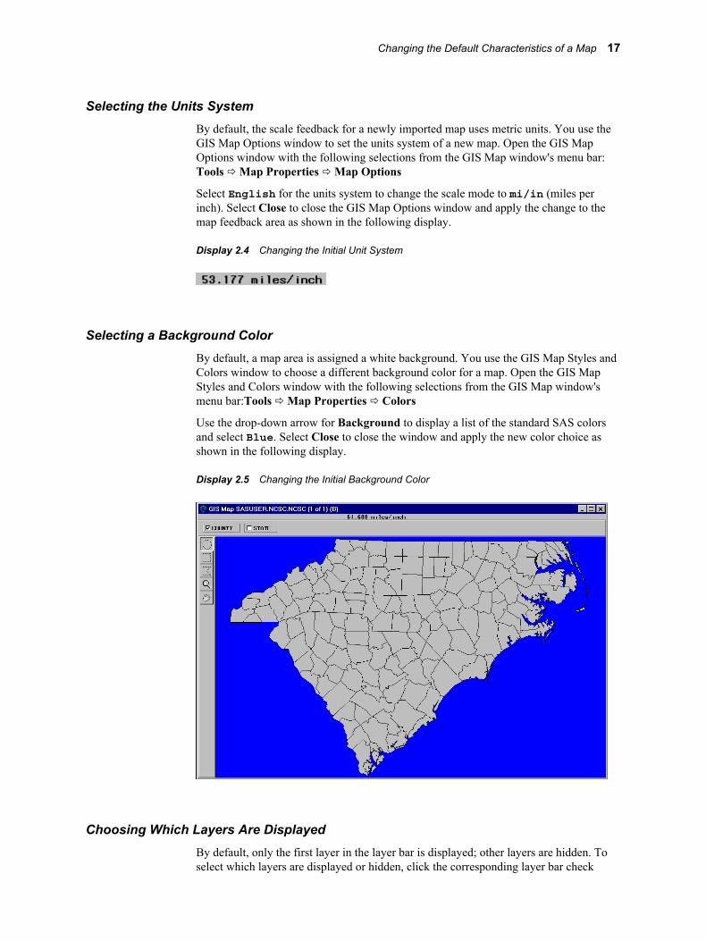
Selecting the Units SystemBy default, the scale feedback for a newly imported map uses metric units. You use theGIS Map Options window to set the units system of a new map. Open the GIS MapOptions window with the following selections from the GIS Map window's menu bar:Tools ð Map Properties ð Map Options
Select English for the units system to change the scale mode to mi/in (miles perinch). Select Close to close the GIS Map Options window and apply the change to themap feedback area as shown in the following display.
Display 2.4 Changing the Initial Unit System
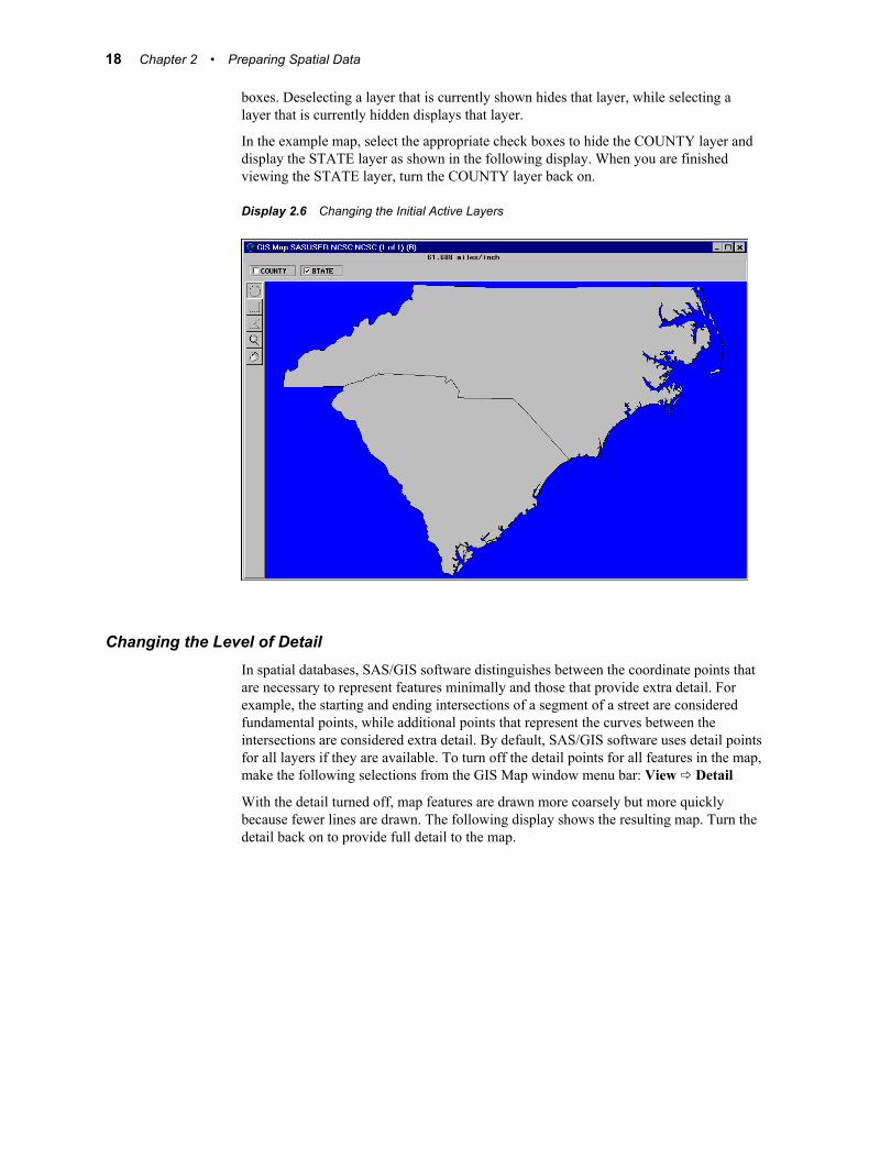
Selecting a Background ColorBy default, a map area is assigned a white background. You use the GIS Map Styles andColors window to choose a different background color for a map. Open the GIS MapStyles and Colors window with the following selections from the GIS Map window'smenu bar:Tools ð Map Properties ð Colors
Use the drop-down arrow for Background to display a list of the standard SAS colorsand select Blue. Select Close to close the window and apply the new color choice asshown in the following display.
Display 2.5 Changing the Initial Background Color
Choosing Which Layers Are DisplayedBy default, only the first layer in the layer bar is displayed; other layers are hidden. Toselect which layers are displayed or hidden, click the corresponding layer bar check
Changing the Default Characteristics of a Map 17
boxes. Deselecting a layer that is currently shown hides that layer, while selecting alayer that is currently hidden displays that layer.
In the example map, select the appropriate check boxes to hide the COUNTY layer anddisplay the STATE layer as shown in the following display. When you are finishedviewing the STATE layer, turn the COUNTY layer back on.
Display 2.6 Changing the Initial Active Layers
Changing the Level of DetailIn spatial databases, SAS/GIS software distinguishes between the coordinate points thatare necessary to represent features minimally and those that provide extra detail. Forexample, the starting and ending intersections of a segment of a street are consideredfundamental points, while additional points that represent the curves between theintersections are considered extra detail. By default, SAS/GIS software uses detail pointsfor all layers if they are available. To turn off the detail points for all features in the map,make the following selections from the GIS Map window menu bar: View ð Detail
With the detail turned off, map features are drawn more coarsely but more quicklybecause fewer lines are drawn. The following display shows the resulting map. Turn thedetail back on to provide full detail to the map.
18 Chapter 2 • Preparing Spatial Data
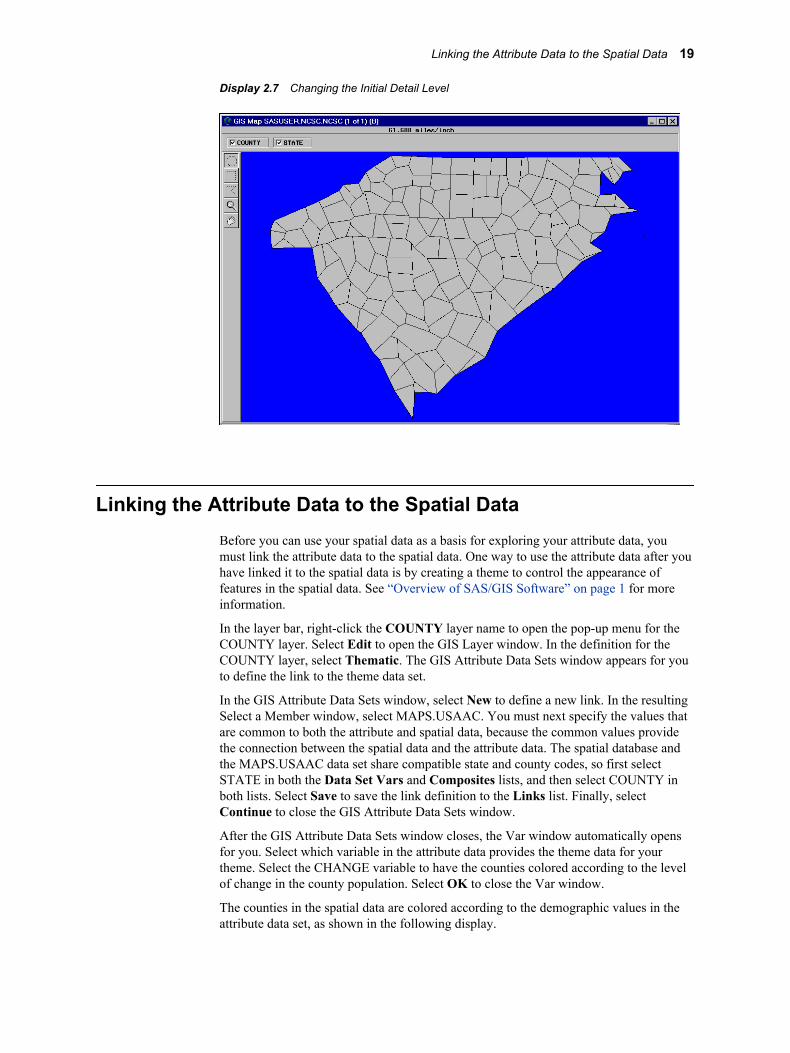
Display 2.7 Changing the Initial Detail Level
Linking the Attribute Data to the Spatial DataBefore you can use your spatial data as a basis for exploring your attribute data, youmust link the attribute data to the spatial data. One way to use the attribute data after youhave linked it to the spatial data is by creating a theme to control the appearance offeatures in the spatial data. See “Overview of SAS/GIS Software” on page 1 for moreinformation.
In the layer bar, right-click the COUNTY layer name to open the pop-up menu for theCOUNTY layer. Select Edit to open the GIS Layer window. In the definition for theCOUNTY layer, select Thematic. The GIS Attribute Data Sets window appears for youto define the link to the theme data set.
In the GIS Attribute Data Sets window, select New to define a new link. In the resultingSelect a Member window, select MAPS.USAAC. You must next specify the values thatare common to both the attribute and spatial data, because the common values providethe connection between the spatial data and the attribute data. The spatial database andthe MAPS.USAAC data set share compatible state and county codes, so first selectSTATE in both the Data Set Vars and Composites lists, and then select COUNTY inboth lists. Select Save to save the link definition to the Links list. Finally, selectContinue to close the GIS Attribute Data Sets window.
After the GIS Attribute Data Sets window closes, the Var window automatically opensfor you. Select which variable in the attribute data provides the theme data for yourtheme. Select the CHANGE variable to have the counties colored according to the levelof change in the county population. Select OK to close the Var window.
The counties in the spatial data are colored according to the demographic values in theattribute data set, as shown in the following display.
Linking the Attribute Data to the Spatial Data 19
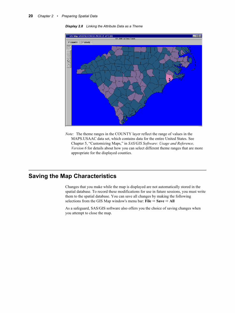
Display 2.8 Linking the Attribute Data as a Theme
Note: The theme ranges in the COUNTY layer reflect the range of values in theMAPS.USAAC data set, which contains data for the entire United States. SeeChapter 5, “Customizing Maps,” in SAS/GIS Software: Usage and Reference,Version 6 for details about how you can select different theme ranges that are moreappropriate for the displayed counties.
Saving the Map CharacteristicsChanges that you make while the map is displayed are not automatically stored in thespatial database. To record these modifications for use in future sessions, you must writethem to the spatial database. You can save all changes by making the followingselections from the GIS Map window's menu bar: File ð Save ð All
As a safeguard, SAS/GIS software also offers you the choice of saving changes whenyou attempt to close the map.
20 Chapter 2 • Preparing Spatial Data
Chapter 3
Importing Spatial Data
Overview of Importing Spatial Data . . . . . . . . . . . . . . . . . . . . . . . . . . . . . . . . . . . . . . 21
The GIS Spatial Data Importing Window . . . . . . . . . . . . . . . . . . . . . . . . . . . . . . . . . 22Opening the GIS Spatial Data Importing Window . . . . . . . . . . . . . . . . . . . . . . . . . . 22Elements of the GIS Spatial Data Importing Window . . . . . . . . . . . . . . . . . . . . . . . 23Command Buttons . . . . . . . . . . . . . . . . . . . . . . . . . . . . . . . . . . . . . . . . . . . . . . . . . . 25
Common Importing Procedures . . . . . . . . . . . . . . . . . . . . . . . . . . . . . . . . . . . . . . . . . 25
Importing ArcInfo Interchange Data . . . . . . . . . . . . . . . . . . . . . . . . . . . . . . . . . . . . . 26
Importing DLG Data . . . . . . . . . . . . . . . . . . . . . . . . . . . . . . . . . . . . . . . . . . . . . . . . . . 27
Importing DXF Data . . . . . . . . . . . . . . . . . . . . . . . . . . . . . . . . . . . . . . . . . . . . . . . . . . 28
Importing Dynamap Data . . . . . . . . . . . . . . . . . . . . . . . . . . . . . . . . . . . . . . . . . . . . . . 28
Importing MapInfo Data . . . . . . . . . . . . . . . . . . . . . . . . . . . . . . . . . . . . . . . . . . . . . . . 30
Importing SAS/GRAPH Map Data Sets . . . . . . . . . . . . . . . . . . . . . . . . . . . . . . . . . . . 30
Importing TIGER Data . . . . . . . . . . . . . . . . . . . . . . . . . . . . . . . . . . . . . . . . . . . . . . . . 31
Importing Generic Spatial Data . . . . . . . . . . . . . . . . . . . . . . . . . . . . . . . . . . . . . . . . . 33Types of Generic Spatial Data . . . . . . . . . . . . . . . . . . . . . . . . . . . . . . . . . . . . . . . . . 33Importing Generic Point (GENPOINT) Data . . . . . . . . . . . . . . . . . . . . . . . . . . . . . . 33Importing Generic Line (GENLINE) Data . . . . . . . . . . . . . . . . . . . . . . . . . . . . . . . . 34Importing Generic Polygon (GENPOLY) Data . . . . . . . . . . . . . . . . . . . . . . . . . . . . 35
Defining Composites in Imported Data . . . . . . . . . . . . . . . . . . . . . . . . . . . . . . . . . . . 36
Defining Layers in Imported Data . . . . . . . . . . . . . . . . . . . . . . . . . . . . . . . . . . . . . . . 37
The SASHELP.GISIMP Data Set . . . . . . . . . . . . . . . . . . . . . . . . . . . . . . . . . . . . . . . . 39
Overview of Importing Spatial DataSAS/GIS software organizes spatial databases into SAS data sets and SAS catalogentries. Spatial data might be available from some vendors in the required SAS/GISformat, but any spatial data that is not in this format must be imported before it can beused with SAS/GIS software. SAS/GIS software provides interactive facilities forimporting spatial data from the following formats:
uncompressed ArcInfo interchange files (E00).produced by ArcInfo software from ESRI.
21
Digital Line Graph files (DLG)from the U.S. Geological Survey and commercial data vendors.
Drawing Interchange Files (DXF)produced by a variety of mapping and CAD software applications.
Dynamap filesfrom Tele Atlas N.V.
SAS/GRAPH map data setsprovided with SAS/GRAPH software.
Topologically Integrated Geographic Encoding and Referencing files (TIGER)from the U.S. Census Bureau and commercial data vendors.
MapInfo files (MIF and MID)from MapInfo Corporation.
SAS/GIS software also supports a generic format to accommodate other sources ofspatial data for which no explicit importing facility is provided. You can use SASprogramming statements to translate your spatial data into the generic format and thenuse SAS/GIS software to complete the process of importing it into a SAS/GIS spatialdatabase. See “Importing Generic Spatial Data” on page 33 for more information aboutthe generic import types.
SAS/GIS provides both interactive and programmatic ways to import spatial data. Theremainder of this chapter explains how to import spatial data interactively using the GISSpatial Data Importing window. See “Batch Importing” on page 41 for informationabout how to import spatial data programmatically.
The GIS Spatial Data Importing Window
Opening the GIS Spatial Data Importing WindowThe GIS Spatial Data Importing window provides an interactive facility for importingspatial data from other formats into SAS/GIS spatial databases. You use the GIS SpatialData Importing window to specify the type of spatial data to import. To open the GISSpatial Data Importing window, select File ð Import from the GIS Map window'smenu bar, or select Import from the map pop-up menu when no map is displayed.
22 Chapter 3 • Importing Spatial Data
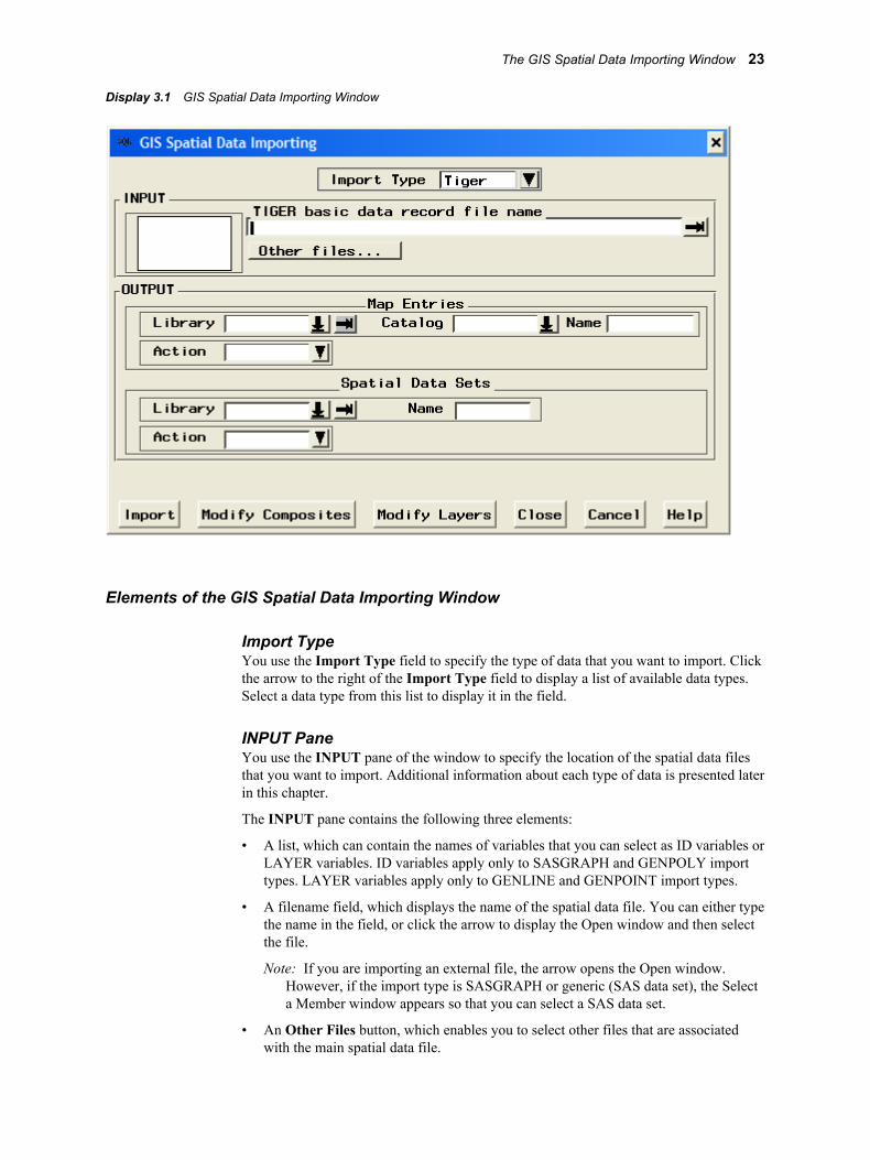
Display 3.1 GIS Spatial Data Importing Window
Elements of the GIS Spatial Data Importing Window
Import TypeYou use the Import Type field to specify the type of data that you want to import. Clickthe arrow to the right of the Import Type field to display a list of available data types.Select a data type from this list to display it in the field.
INPUT PaneYou use the INPUT pane of the window to specify the location of the spatial data filesthat you want to import. Additional information about each type of data is presented laterin this chapter.
The INPUT pane contains the following three elements:
• A list, which can contain the names of variables that you can select as ID variables orLAYER variables. ID variables apply only to SASGRAPH and GENPOLY importtypes. LAYER variables apply only to GENLINE and GENPOINT import types.
• A filename field, which displays the name of the spatial data file. You can either typethe name in the field, or click the arrow to display the Open window and then selectthe file.
Note: If you are importing an external file, the arrow opens the Open window.However, if the import type is SASGRAPH or generic (SAS data set), the Selecta Member window appears so that you can select a SAS data set.
• An Other Files button, which enables you to select other files that are associatedwith the main spatial data file.
The GIS Spatial Data Importing Window 23
Note: The Other Files button usually applies only to the TIGER, MAPINFO, andDYNAMAP import types. Other data types might not have any additional spatialdata files.
OUTPUT PaneThe OUTPUT pane of the window contains the following two sections:
Map EntriesYou specify the storage location of the spatial database in this pane.
In the Library field, you specify a name for the library that you want to contain thecatalog and its entries. You can type the name of an existing library in the field, usethe drop-down menu to select an existing libref, or use the pull-out menu to assign anew libref.
In the Catalog field, you specify a name for the SAS catalog that you want tocontain the spatial database entries. You can type the name of a new catalog to becreated, type the name of an existing catalog, or use the drop-down menu to select anexisting catalog.
In the Name field, you specify a name for the GIS map. By default, the Name fieldcontains the name of the spatial data import type, for example, TIGER, ARC, DXF,and so on. You can supply your own GIS map name. This name is also used for thecoverage entry and as the base name of the polygonal index data set by using the firstthree letters of the name, and then by adding up to the first five letters of the layername.
In the Action field, you select options regarding the catalog entries. The drop-downmenu to the right of the field contains the following options:
CREATEcreates new catalog entries.
REPLACEoverwrites existing catalog entries. REPLACE will create new catalog entries ifno entries exist for it to overwrite.
UPDATEupdates existing catalog entries.
Spatial Data SetsIn this pane, you specify the name of the SAS library in which the chains, nodes,details, and polygonal index data sets are stored along with the base name for thechains, nodes, and details data sets and spatial entry.
In the Library field, you specify a name for the library that you want to contain thedata sets. You can type the name of an existing library in the field, use the drop-down menu to select an existing libref, or use the pull-out menu to assign a newlibref.
In the Name field, you specify a base name for the data sets. The chains, nodes, anddetails data set names are formed by adding a C, N, or D, respectively, to this basename. The base name is also used as the name for the spatial entry in the catalog.
In the Action field, you select options regarding the data sets. The drop-down menuto the right of the field contains the following options:
CREATEcreates new data sets.
24 Chapter 3 • Importing Spatial Data
REPLACEoverwrites existing data sets. REPLACE creates new data sets if no data setsexist for it to overwrite.
APPENDappends to existing data sets.
Command ButtonsThe command buttons appear in a row along the lower edge of the GIS Spatial DataImporting window. The following list describes the different functions of the commandbuttons:
Importstarts the importing process, provided that all required information has beensupplied.
Modify Compositesopens a window to view and modify the default composites that are created duringthe import.
Modify Layersopens a window to view and modify the default layer definitions that are createdduring the import.
Closecloses the GIS Spatial Data Importing window and returns to the GIS Map windowwith the imported map displayed.
Cancelcloses the GIS Spatial Data Importing window. If a map was imported, it is notdisplayed in the GIS Map window.
Helpopens the online Help facility for the GIS Spatial Data Importing window. The Helpprovides details about the steps for importing the corresponding type of spatial data.
Common Importing ProceduresThe following instructions detail the process that is common to importing all acceptedtypes of spatial data. For additional information about preparing and importing specifictypes of data, see the sections that follow.
To import spatial data, complete the following steps:
1. Select File ð Import from the GIS Map window's menu bar or select Import fromthe map pop-up menu when no map is displayed.
The GIS Spatial Data Importing window appears.
2. Select the type of data to import from the Import Type field drop-down menu.
3. Select the file to import from the pull-out menu to the right of the filename field inthe INPUT pane. Or, supply the path and filename or SAS data set name in thisfield.
Common Importing Procedures 25
After you have selected an input file, the OUTPUT fields are filled with the defaultvalues. See “The SASHELP.GISIMP Data Set” on page 39 for information aboutchanging the default values.
4. Modify the default composites, if needed. Click Modify Composites and make yourchanges in the Modify Composites window that appears. This step is optional. See“Defining Composites in Imported Data” on page 36 for more information.
Note: The composite definitions in the Modify Composites window can have astatus of either Keep or Drop. Associations with the Drop status are notincluded in the SAS/GIS spatial database even though they appear in the variablelist in the Modify Composites window.
5. Modify the layers, if needed. Click Modify Layers and make your changes in theModify Layers window that appears. This step is optional. See “Defining Layers inImported Data” on page 37 for more information.
6. Modify the Library, Catalog, Name, and Action field information in the MapEntries pane to specify the destination location of the catalog and its entries, ifneeded.
Note: The Library, Catalog, Name, and Action fields contain default values thatare based on the input file that you selected earlier in this process. You canmodify these values or accept the defaults.
7. Modify the Library, Name, and Action field information in the Spatial Data Setspane to specify the destination location of the spatial data sets, if needed.
Note: These fields contain default values that are based on the input file that youselected earlier in the import process. You can modify these values or accept thedefaults.
8. Click the Import button.
Once the import has finished, the following message appears in the window messagebar: Import Complete. Close this window to display the map.
CAUTION:Be careful when using Modify Composites and Modify Layers, especially whenappending new information to an existing map. Modifying the default compositesand layers can cause unexpected results or errors. If you are unsure about makingmodifications, you should keep the default composites and layers as they are duringimporting. After you import the map, you can view it and review the composites andlayers that were created and then use the GIS procedure to make modifications later.
Importing ArcInfo Interchange DataArcInfo software supports several spatial data formats, but SAS/GIS software can importonly spatial data that has been exported from ArcInfo software in uncompressedinterchange format (sometimes called E00 files because the files have the extension .e00by default). If you do not know whether a file is compressed, open the file with a hosteditor. If you can read text in the file, it is not compressed.
To import spatial data in uncompressed ArcInfo interchange format using the GISSpatial Data Importing window, complete the following steps:
1. Select ARC from the Import Type drop-down menu.
26 Chapter 3 • Importing Spatial Data

The title of the filename field in the INPUT pane changes to ARC/INFO Coverageexport filename.
2. Specify the path to the desired ArcInfo file, either by typing the path in the filenamefield, or by clicking the arrow to display an Open window and then selecting the filefrom that window.
By default, SAS/GIS expects ArcInfo interchange files to have an extension of .e00.
SAS/GIS allocates the SAS fileref ARCIN to the import path that you specified inthe filename field. If you allocate the fileref ARCIN to the desired file before youbegin the import process, the filename and path appears in the filename fieldautomatically.
3. Modify the destination information for the catalog and the spatial data sets, ifneeded.
4. Modify the default layers and composites, if needed. For more information, see thefollowing:
• “Defining Layers in Imported Data” on page 37
• “Defining Composites in Imported Data” on page 36
5. Click Import to import the data. When the import process is complete, a message isdisplayed in the window message bar to indicate whether the import was successful.You can proceed with another import or close the window to display the newlyimported map.
Importing DLG DataTo import spatial data in Digital Line Graph (DLG) format using the GIS Spatial DataImporting window, complete the following steps:
1. Select DLG from the Import Type drop-down menu.
The title of the filename field in the INPUT pane changes to Digital LineGraph filename.
2. Specify the path to the desired DLG file, either by typing the path in the filenamefield, or by clicking the arrow to display an Open window and then selecting the filefrom that window. SAS/GIS software checks whether the DLG file type is Standardor Optional and processes the types accordingly.
SAS/GIS allocates the SAS fileref DLGIN to the import path that you specified inthe filename field. If you allocate the fileref DLGIN to the desired file beforebeginning the import process, the filename and path appear in the filename fieldautomatically.
3. Modify the destination information for the catalog and the spatial data sets, ifneeded.
4. Modify the default layers and composites, if needed. For more information, see thefollowing:
• “Defining Layers in Imported Data” on page 37
• “Defining Composites in Imported Data” on page 36
No more than one layer of each type can be created from a DLG file. The fields forany layer types that cannot be created are dimmed.
Importing DLG Data 27
5. Click Import to import the data. When the import process is complete, a message isdisplayed in the window message bar to indicate whether the import was successful.You can proceed with another import or close the window to display the newlyimported map.
Importing DXF DataDrawing Interchange File (DXF) files are typically output from CAD systems. DXF filesoften contain only lines and points. If you want to create polygons in the importedSAS/GIS map, then you must ensure that the boundary lines for the closed panes in theDXF file are topologically correct. Although the lines might appear to form a closedpolygon in the CAD system, the polygon creation process will fail if the end point of oneboundary line is not the same as the beginning point of the next line.
The SAS/GIS import process does not support DXF symbols or blocks. If parts of theimported drawing do not appear as expected, then examine the source of the DXF file. Ifit contains AutoCAD blocks, then the data provider can explode these blocks intoseparate elements and then export a new DXF file.
To import spatial data in DXF format using the GIS Spatial Data Importing window,complete the following steps:
1. Select DXF from the Import Type drop-down menu.
The title of the filename field in the INPUT pane changes to DXF filename.
2. Specify the path to the desired DXF file, either by typing the path in the filenamefield, or by clicking the arrow to display an Open window and then selecting the filefrom that window.
SAS/GIS allocates the SAS fileref DXFIN to the import path that you specified inthe filename field. If you allocate the fileref DXFIN to the desired file beforebeginning the import process, the filename and path appear in the filename fieldautomatically.
3. Modify the destination information for the catalog and the spatial data sets, ifneeded.
4. Modify the default layers and composites, if needed. For more information, see thefollowing:
• “Defining Layers in Imported Data” on page 37
• “Defining Composites in Imported Data” on page 36
5. Click Import to import the data. When the import process is complete, a message isdisplayed in the window message bar to indicate whether the import was successful.You can proceed with another import or close the window to display the newlyimported map.
Importing Dynamap DataTo import spatial data in Dynamap format using the GIS Spatial Data Importingwindow, complete the following steps:
28 Chapter 3 • Importing Spatial Data

1. Select Dynamap from the Import Type drop-down menu.
The title of the filename field in the INPUT pane changes to Dynamap basicdata record filename.
2. Specify the path to the desired Dynamap basic data record file, either by typing thepath in the filename field, or by clicking the arrow to display an Open window andthen selecting the file from that window. The basic data record file is a Type 1Dynamap file, and it contains a record for each line segment in the file. This file isrequired.
SAS/GIS software allocates the SAS fileref GDT1 to the import path that youspecified in the filename field. If you allocate the fileref GDT1 to the desired filebefore beginning the import process, the filename and path appear in the filenamefield automatically.
3. Click Other Files
A window appears and displays filename fields for the remainder of the Dynamapfiles that are needed. If the files are in the same directory as the basic data record file,the path is specified automatically. Specify the following files:
Shape coordinate pointsprovide additional coordinates that describe the shape of each line segment, forexample, a curve in the road. These coordinates are SAS/GIS detail points. Thisfile is a Type 2 Dynamap file and has a corresponding fileref of GDT2. This fileis required.
Index to alternate feature namesprovides the names if a line segment has more than one feature name, forexample, Main St. and State Highway 1010. This file is a Type 4 Dynamap fileand has a corresponding fileref of GDT4. This file is optional and is not selectedby default. To read in the data from this file, select the Read On/Off check box.
Feature name listprovides a list of all unique feature names. This file is a Type 5 Dynamap file andhas a corresponding fileref of GDT5. This file is optional and is not selected bydefault. To read in the data from this file, select the Read On/Off check box.
Additional address and ZIP code dataprovides additional address range information if the address information cannotbe presented as a single address range. This file is a Type 6 Dynamap file and hasa corresponding fileref of GDT6. This file is optional and is not selected bydefault. To read in the data from this file, select the Read On/Off check box.
Click OK when you have specified the paths for the Dynamap files to return to theGIS Spatial Data Importing window.
4. Modify the destination information for the catalog and the spatial data sets, ifneeded.
5. Modify the default layers and composites, if needed. For more information, see thefollowing:
• “Defining Layers in Imported Data” on page 37
• “Defining Composites in Imported Data” on page 36
6. Click Import to import the data. When the import process is complete, a message isdisplayed in the window message bar to indicate whether the import was successful.You can proceed with another import or close the window to display the newlyimported map.
Importing Dynamap Data 29
Importing MapInfo DataTo import spatial data in MapInfo (MIF and MID) format using the GIS Spatial DataImporting window, complete the following steps:
1. Select Mapinfo from the Import Type drop-down menu.
The title of the filename field in the INPUT pane changes to MAPINFO MIFfilename.
2. Specify the path to the desired MapInfo MIF file, either by typing the path in thefilename field, or by clicking the arrow to display an Open window, and thenselecting the file from that window. The MIF file has an extension of .mif andcontains graphic objects.
SAS/GIS allocates the SAS fileref MIF to the import path that you specified in thefilename field. If you allocate the fileref MIF to the desired file before beginning theimport process, the filename and path appear in the filename field automatically.
3. Click Other Files, and then enter or select the path for the MapInfo MID file in thewindow that appears. If the MID file is in the same directory as the MIF file,SAS/GIS software automatically sets the path to the MID file. The MID file has anextension of .mid and contains tabular data. SAS/GIS allocates the SAS fileref MIDto the import path that you specified in the filename field. If you allocate the filerefMID to the desired file before beginning the import process, the filename and pathappears in the filename field automatically.
Click OK when you have specified the path for the MID file to return to the GISSpatial Data Importing window.
4. Modify the destination information for the catalog and the spatial data sets, ifneeded.
5. Modify the default layers and composites, if needed. For more information, see thefollowing:
• “Defining Layers in Imported Data” on page 37
• “Defining Composites in Imported Data” on page 36
6. Click Import to import the data. When the import process is complete, a message isdisplayed in the window message bar to indicate whether the import was successful.You can proceed with another import or close the window to display the newlyimported map.
Importing SAS/GRAPH Map Data SetsTo import spatial data in SASGRAPH format using the GIS Spatial Data Importingwindow, complete the following steps:
1. Select SASGRAPH from the Import Type drop-down menu.
The title of the filename field in the INPUT pane changes to SAS/GRAPH dataset.
30 Chapter 3 • Importing Spatial Data
2. Specify the library and data set name of the desired SAS/GRAPH data, either bytyping the data set name in the data set name field, or by clicking the arrow todisplay a Select A Member window and then selecting the data set from thatwindow.
3. Select the variables from the ID Vars field that you want to use as ID variables. IDvariables are variables whose values uniquely identify unit areas in the map. TypicalID variables in SAS/GRAPH maps are COUNTRY, ID, STATE, and COUNTY. Aseparate layer is created for each ID variable. The ID variables must be selected inhierarchical order. For example, if the data set contains both STATE and COUNTYvariables, then STATE must be selected before COUNTY.
4. Modify the destination information for the catalog and the spatial data sets, ifneeded.
5. Modify the default layers and composites, if needed. For more information, see thefollowing:
• “Defining Layers in Imported Data” on page 37
• “Defining Composites in Imported Data” on page 36
6. Click Import to import the data. When the import process is complete, a message isdisplayed in the window message bar to indicate whether the import was successful.You can proceed with another import or close the window to display the newlyimported map.
Importing TIGER DataTo import spatial data in the 2006 Second Edition of Topologically IntegratedGeographic Encoding and Referencing (TIGER) format using the GIS Spatial DataImporting window, complete the following steps:
1. Select Tiger from the Import Type drop-down menu.
The title of the filename field in the INPUT pane changes to TIGER basic datarecord filename.
2. Specify the path to the desired TIGER basic data record file, either by typing thepath in the filename field, or by clicking the arrow to display an Open window andthen selecting the file from that window.
Each TIGER map consists of a set of files with names of the form TGRssccc.Fvn,where
ssis the two-digit FIPS code for the state.
cccis the three-digit FIPS code for the county.
Note: Refer to the documentation that accompanies the TIGER data for adirectory of the FIPS codes for each state and county.
videntifies the TIGER version number.
nidentifies the TIGER record type. The basic data record is Type 1.
Importing TIGER Data 31
SAS/GIS allocates the SAS fileref TIGER1 to the import path that you specified inthe filename field. If you allocate the fileref TIGER1 to the desired file beforebeginning the import process, the filename and path appear in the filename fieldautomatically.
3. Click Other Files, and then type or select the path for the other TIGER data files inthe window that appears. If the files are in the same directory as the basic data recordfile, SAS/GIS software automatically sets the path to the other files. Specify thefollowing files:
Shape coordinate pointsprovides additional coordinates that describe the shape of each line segment, forexample, a curve in the road. These coordinates are SAS/GIS detail points. Thisfile is required and is selected by default. This file is a Type 2 TIGER file.SAS/GIS allocates the fileref TIGER2 to this path.
Index to alternate feature namesprovides the names if a line segment has more than one feature name, forexample, Main St. and State Highway 1010. This file is optional and is notselected by default. To read in the data from this file, select the Read On/Offcheck box. This file is a Type 4 TIGER file. SAS/GIS allocates the filerefTIGER4 to this path.
Feature name listprovides a list of all unique feature names. This file is optional and is not selectedby default. To read in the data from this file, select the Read On/Off check box.This file is a Type 5 TIGER file. SAS/GIS allocates the fileref TIGER5 to thispath.
Additional address and ZIP code dataprovides additional address range information if the address information cannotbe presented as a single address range. This file is optional and is not selected bydefault. To read in the data from this file, select the Read On/Off check box.SAS/GIS allocates the fileref TIGER6 to this path.
When you have specified the paths for the TIGER files, click OKto return to the GISSpatial Data Importing window.
4. Modify the destination information for the catalog and the spatial data sets, ifneeded.
5. Modify the default layers and composites, if needed. For more information, see thefollowing:
• “Defining Layers in Imported Data” on page 37
• “Defining Composites in Imported Data” on page 36
Note: By default, the following composites are assigned Drop status and will notappear in the imported data. Refer to the documentation for TIGER/Line files formore information about these composites.
AIR ANC IADDR RECTYPE SIDECODE SOURCE
6. Click Import to import the data. When the import process is complete, a message isdisplayed in the window message bar to indicate whether the import was successful.You can proceed with another import or close the window to display the newlyimported map.
Note: SAS/GIS can import 2006 Second Edition TIGER/Line files from the U.S.Census Bureau and earlier releases of the TIGER/Line spatial data format. Contact
32 Chapter 3 • Importing Spatial Data
SAS Technical Support for the latest information about the availability of support forimporting files from 2007 TIGER/Line Shapefiles.
Importing Generic Spatial Data
Types of Generic Spatial DataSAS/GIS software provides facilities for creating spatial databases from SAS data setsthat contains the following types of generic spatial data:
point (GENPOINT)consists of discrete points.
line (GENLINE)consists of discrete line segments.
polygon (GENPOLY)consists of areas that are enclosed by polylines.
You can use the generic import methods if your data is in a format other than the specificimport types that were discussed earlier. The generic import methods are useful forcombining map features with an existing map. However, when adding generic data toexisting spatial data sets, you must ensure that coordinate systems match.
Importing Generic Point (GENPOINT) DataTo import a SAS data set that contains point data, use the GIS Spatial Data Importingwindow to complete the following steps:
1. Select Genpoint from the Import Type drop-down menu.
The title of the filename field in the INPUT pane changes to SAS/GIS GenericPoint data set.
2. Specify the desired SAS data set, either by typing the location in the data set field orby clicking the arrow to display the Select a Member window and then selecting thedata set from that window.
The point data set must contain at least the following variables:
Xeast-west coordinate of the point.
Ynorth-south coordinate of the point.
IDidentifier value for the point.
Note: Each observation in the data set must have a unique value for the IDvariable.
The data set can also contain other variables, for example, variables to definecharacteristics of the points.
3. Select the variable from the ID Vars field that you want to use as an ID variable.SAS/GIS software performs a frequency analysis on the values of the specifiedvariable in the point data set and creates a point layer for each unique value of thespecified variable. If you specify more than 16 layers, only the first 16 are added to
Importing Generic Spatial Data 33

the map. If you do not specify a layer variable, the resulting map will have a singlepoint layer with the same name as the original point data set.
4. Modify the destination information for the catalog and the spatial data sets, ifneeded.
5. Modify the default layers and composites, if needed. For more information, see thefollowing:
• “Defining Layers in Imported Data” on page 37
• “Defining Composites in Imported Data” on page 36
6. Click Import to import the data. When the import process is complete, a message isdisplayed in the window message bar to indicate whether the import was successful.You can proceed with another import or close the window to display the newlyimported map.
Importing Generic Line (GENLINE) DataTo import a SAS data set that contains line data, use the GIS Spatial Data Importingwindow to complete the following steps:
1. Select Genline from the Import Type drop-down menu.
The title of the filename field in the INPUT pane changes to SAS/GIS GenericLine data set.
2. Specify the desired SAS data set, either by typing the location in the data set field, orby clicking the arrow to display the Select a Member window and then selecting thedata set from that window.
The line data set must contain at least the following variables:
Xeast-west coordinate of a point on the line.
Ynorth-south coordinate of a point on the line.
IDidentifier value for the line.
Note: Each line in the data set must have a unique ID value, and all observationsfor the points on each line must have the same value for the ID variable.
The data set can also contain other variables, for example, variables to definecharacteristics of the lines.
3. Select the variable from the ID Vars field that you want to use as an ID variable.SAS/GIS software performs a frequency analysis on the values of the specifiedvariable and creates a line layer for each unique value of the specified variable. Ifmore than 16 layers are created, only the first 16 are added to the map by default. Ifyou do not specify a layer variable, the resulting map will have a single line layerwith the same name as the original line data set.
4. Modify the destination information for the catalog and the spatial data sets, ifneeded.
5. Modify the default layers and composites, if needed For more information, see thefollowing:
• “Defining Layers in Imported Data” on page 37
34 Chapter 3 • Importing Spatial Data

• “Defining Composites in Imported Data” on page 36
6. Click Import to import the data. When the import process is complete, a message isdisplayed in the window message bar to indicate whether the import was successful.You can proceed with another import or close the window to display the newlyimported map.
Importing Generic Polygon (GENPOLY) DataTo import a SAS data set that contains polygon data, use the GIS Spatial Data Importingwindow to complete the following steps:
1. Select Genpoly from the Import Type drop-down menu.
The title of the filename field in the INPUT pane changes to SAS/GIS GenericPolygon data set.
2. Specify the desired SAS data set, either by typing the location in the data set field, orby clicking the arrow to display the Select a Member window and then selecting thedata set from that window.
The polygon data set must contain at least the following variables:
Xeast-west coordinate of a point on the polygon boundary.
Ynorth-south coordinate of a point on the polygon boundary.
ID-name(s)identifier value(s) for the polygonal area.
Note: Each polygonal area in the data set should have unique identifier values,and all observations for the points in each area should have the sameidentifier value. A polygonal area can consist of more than one polygon. Inthat case the data set should also contain a SEGMENT variable to distinguishthe individual polygons.
Any other variables in the data set will not be included in the spatial database.
3. Select the variables from the ID Vars field that you want to use as ID variables. IDvariables are variables whose values uniquely identify unit areas in the map. Aseparate layer is created for each ID variable. The ID variables must be selected inhierarchical order. For example, if the data set contains both STATE and COUNTYvariables, then STATE must be selected before COUNTY.
4. Modify the destination information for the catalog and the spatial data sets, ifneeded.
5. Modify the default layers and composites, if needed. For more information, see thefollowing:
• “Defining Layers in Imported Data” on page 37
• “Defining Composites in Imported Data” on page 36
6. Click Import to import the data. When the import process is complete, a message isdisplayed in the window message bar to indicate whether the import was successful.You can proceed with another import or close the window to display the newlyimported map.
Importing Generic Spatial Data 35
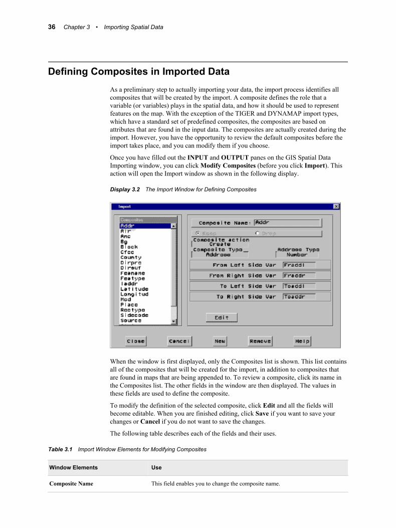
Defining Composites in Imported DataAs a preliminary step to actually importing your data, the import process identifies allcomposites that will be created by the import. A composite defines the role that avariable (or variables) plays in the spatial data, and how it should be used to representfeatures on the map. With the exception of the TIGER and DYNAMAP import types,which have a standard set of predefined composites, the composites are based onattributes that are found in the input data. The composites are actually created during theimport. However, you have the opportunity to review the default composites before theimport takes place, and you can modify them if you choose.
Once you have filled out the INPUT and OUTPUT panes on the GIS Spatial DataImporting window, you can click Modify Composites (before you click Import). Thisaction will open the Import window as shown in the following display.
Display 3.2 The Import Window for Defining Composites
When the window is first displayed, only the Composites list is shown. This list containsall of the composites that will be created for the import, in addition to composites thatare found in maps that are being appended to. To review a composite, click its name inthe Composites list. The other fields in the window are then displayed. The values inthese fields are used to define the composite.
To modify the definition of the selected composite, click Edit and all the fields willbecome editable. When you are finished editing, click Save if you want to save yourchanges or Cancel if you do not want to save the changes.
The following table describes each of the fields and their uses.
Table 3.1 Import Window Elements for Modifying Composites
Window Elements Use
Composite Name This field enables you to change the composite name.
36 Chapter 3 • Importing Spatial Data
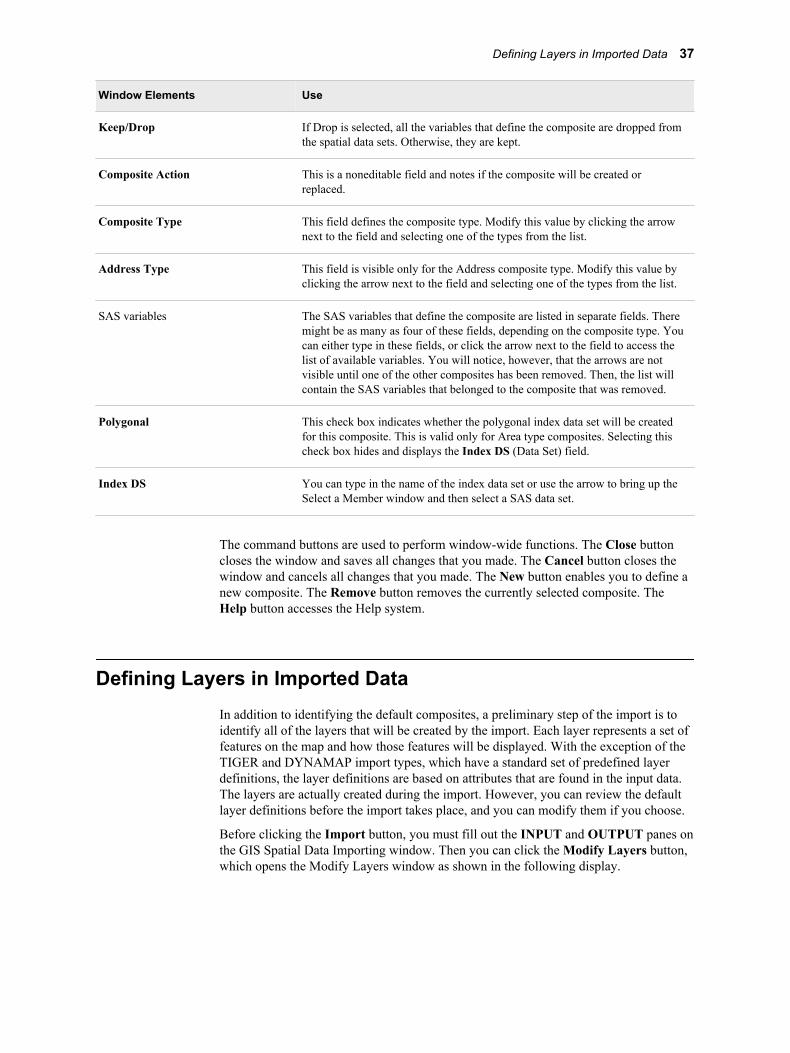
Window Elements Use
Keep/Drop If Drop is selected, all the variables that define the composite are dropped fromthe spatial data sets. Otherwise, they are kept.
Composite Action This is a noneditable field and notes if the composite will be created orreplaced.
Composite Type This field defines the composite type. Modify this value by clicking the arrownext to the field and selecting one of the types from the list.
Address Type This field is visible only for the Address composite type. Modify this value byclicking the arrow next to the field and selecting one of the types from the list.
SAS variables The SAS variables that define the composite are listed in separate fields. Theremight be as many as four of these fields, depending on the composite type. Youcan either type in these fields, or click the arrow next to the field to access thelist of available variables. You will notice, however, that the arrows are notvisible until one of the other composites has been removed. Then, the list willcontain the SAS variables that belonged to the composite that was removed.
Polygonal This check box indicates whether the polygonal index data set will be createdfor this composite. This is valid only for Area type composites. Selecting thischeck box hides and displays the Index DS (Data Set) field.
Index DS You can type in the name of the index data set or use the arrow to bring up theSelect a Member window and then select a SAS data set.
The command buttons are used to perform window-wide functions. The Close buttoncloses the window and saves all changes that you made. The Cancel button closes thewindow and cancels all changes that you made. The New button enables you to define anew composite. The Remove button removes the currently selected composite. TheHelp button accesses the Help system.
Defining Layers in Imported DataIn addition to identifying the default composites, a preliminary step of the import is toidentify all of the layers that will be created by the import. Each layer represents a set offeatures on the map and how those features will be displayed. With the exception of theTIGER and DYNAMAP import types, which have a standard set of predefined layerdefinitions, the layer definitions are based on attributes that are found in the input data.The layers are actually created during the import. However, you can review the defaultlayer definitions before the import takes place, and you can modify them if you choose.
Before clicking the Import button, you must fill out the INPUT and OUTPUT panes onthe GIS Spatial Data Importing window. Then you can click the Modify Layers button,which opens the Modify Layers window as shown in the following display.
Defining Layers in Imported Data 37
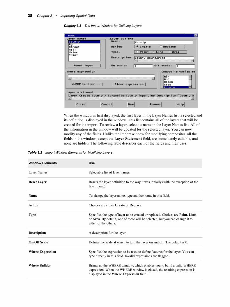
Display 3.3 The Import Window for Defining Layers
When the window is first displayed, the first layer in the Layer Names list is selected andits definition is displayed in the window. This list contains all of the layers that will becreated for the import. To review a layer, select its name in the Layer Names list. All ofthe information in the window will be updated for the selected layer. You can nowmodify any of the fields. Unlike the Import window for modifying composites, all thefields in the window, except the Layer Statement field, are immediately editable, andnone are hidden. The following table describes each of the fields and their uses.
Table 3.2 Import Window Elements for Modifying Layers
Window Elements Use
Layer Names Selectable list of layer names.
Reset Layer Resets the layer definition to the way it was initially (with the exception of thelayer name).
Name To change the layer name, type another name in this field.
Action Choices are either Create or Replace.
Type Specifies the type of layer to be created or replaced. Choices are Point, Line,or Area. By default, one of these will be selected, but you can change it toeither of the others.
Description A description for the layer.
On/Off Scale Defines the scale at which to turn the layer on and off. The default is 0.
Where Expression Specifies the expression to be used to define features for the layer. You cantype directly in this field. Invalid expressions are flagged.
Where Builder Brings up the WHERE window, which enables you to build a valid WHEREexpression. When the WHERE window is closed, the resulting expression isdisplayed in the Where Expression field.
38 Chapter 3 • Importing Spatial Data
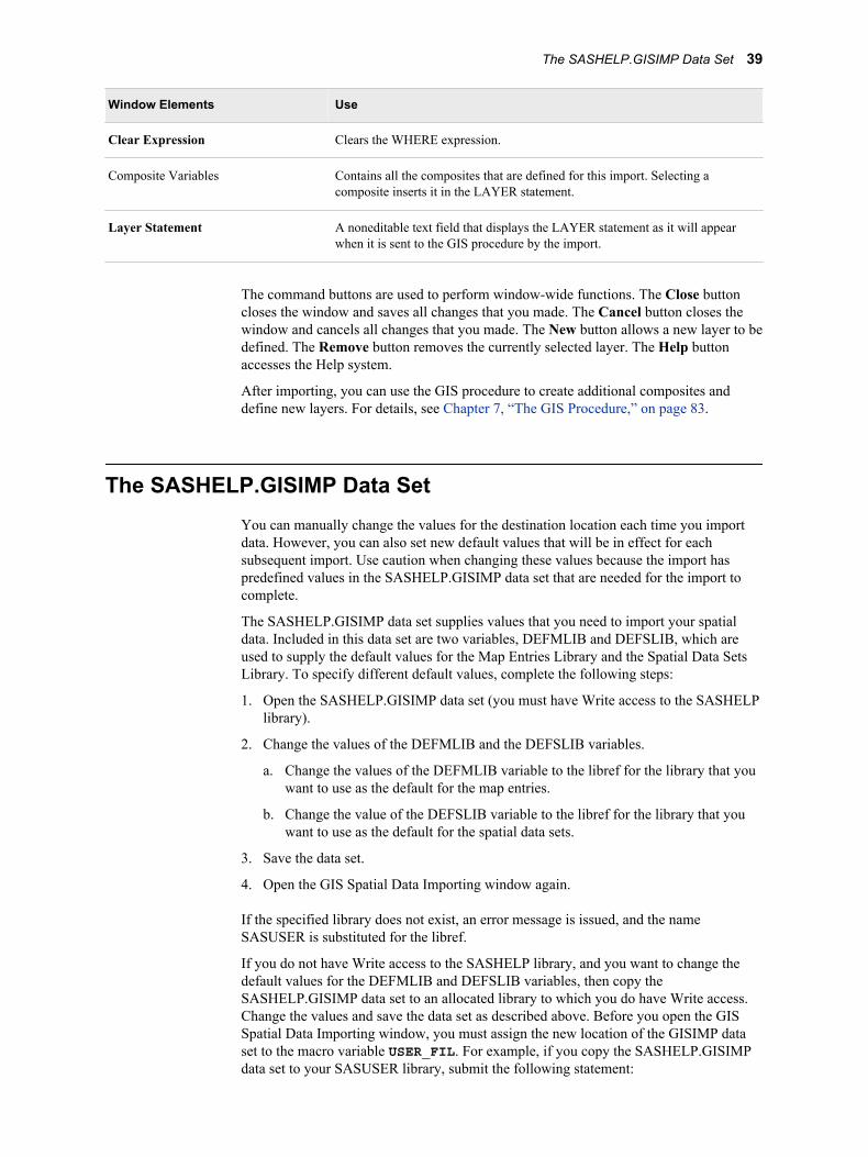
Window Elements Use
Clear Expression Clears the WHERE expression.
Composite Variables Contains all the composites that are defined for this import. Selecting acomposite inserts it in the LAYER statement.
Layer Statement A noneditable text field that displays the LAYER statement as it will appearwhen it is sent to the GIS procedure by the import.
The command buttons are used to perform window-wide functions. The Close buttoncloses the window and saves all changes that you made. The Cancel button closes thewindow and cancels all changes that you made. The New button allows a new layer to bedefined. The Remove button removes the currently selected layer. The Help buttonaccesses the Help system.
After importing, you can use the GIS procedure to create additional composites anddefine new layers. For details, see Chapter 7, “The GIS Procedure,” on page 83.
The SASHELP.GISIMP Data SetYou can manually change the values for the destination location each time you importdata. However, you can also set new default values that will be in effect for eachsubsequent import. Use caution when changing these values because the import haspredefined values in the SASHELP.GISIMP data set that are needed for the import tocomplete.
The SASHELP.GISIMP data set supplies values that you need to import your spatialdata. Included in this data set are two variables, DEFMLIB and DEFSLIB, which areused to supply the default values for the Map Entries Library and the Spatial Data SetsLibrary. To specify different default values, complete the following steps:
1. Open the SASHELP.GISIMP data set (you must have Write access to the SASHELPlibrary).
2. Change the values of the DEFMLIB and the DEFSLIB variables.
a. Change the values of the DEFMLIB variable to the libref for the library that youwant to use as the default for the map entries.
b. Change the value of the DEFSLIB variable to the libref for the library that youwant to use as the default for the spatial data sets.
3. Save the data set.
4. Open the GIS Spatial Data Importing window again.
If the specified library does not exist, an error message is issued, and the nameSASUSER is substituted for the libref.
If you do not have Write access to the SASHELP library, and you want to change thedefault values for the DEFMLIB and DEFSLIB variables, then copy theSASHELP.GISIMP data set to an allocated library to which you do have Write access.Change the values and save the data set as described above. Before you open the GISSpatial Data Importing window, you must assign the new location of the GISIMP dataset to the macro variable USER_FIL. For example, if you copy the SASHELP.GISIMPdata set to your SASUSER library, submit the following statement:
The SASHELP.GISIMP Data Set 39

%LET USER_FIL=SASUSER.GISIMP;
If you want to use the default values for a particular import without having to modify theSASUSER.GISIMP data set, you can reset the USER_FIL macro variable to the defaultSASHELP.GISIMP data set. For example:
%LET USER_FIL=SASHELP.GISIMP;
The import will use the values in the data set that the USER_FIL macro variable pointsto.
40 Chapter 3 • Importing Spatial Data
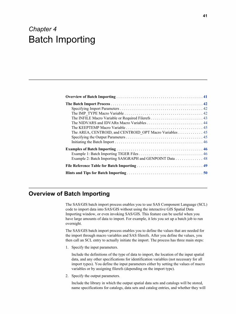
Chapter 4
Batch Importing
Overview of Batch Importing . . . . . . . . . . . . . . . . . . . . . . . . . . . . . . . . . . . . . . . . . . . 41
The Batch Import Process . . . . . . . . . . . . . . . . . . . . . . . . . . . . . . . . . . . . . . . . . . . . . . 42Specifying Import Parameters . . . . . . . . . . . . . . . . . . . . . . . . . . . . . . . . . . . . . . . . . 42The IMP_TYPE Macro Variable . . . . . . . . . . . . . . . . . . . . . . . . . . . . . . . . . . . . . . . 42The INFILE Macro Variable or Required Filerefs . . . . . . . . . . . . . . . . . . . . . . . . . . 43The NIDVARS and IDVARn Macro Variables . . . . . . . . . . . . . . . . . . . . . . . . . . . . 44The KEEPTEMP Macro Variable . . . . . . . . . . . . . . . . . . . . . . . . . . . . . . . . . . . . . . 45The AREA, CENTROID, and CENTROID_OPT Macro Variables . . . . . . . . . . . . 45Specifying the Output Parameters . . . . . . . . . . . . . . . . . . . . . . . . . . . . . . . . . . . . . . 45Initiating the Batch Import . . . . . . . . . . . . . . . . . . . . . . . . . . . . . . . . . . . . . . . . . . . . 46
Examples of Batch Importing . . . . . . . . . . . . . . . . . . . . . . . . . . . . . . . . . . . . . . . . . . . 46Example 1: Batch Importing TIGER Files . . . . . . . . . . . . . . . . . . . . . . . . . . . . . . . . 46Example 2: Batch Importing SASGRAPH and GENPOINT Data . . . . . . . . . . . . . 48
File Reference Table for Batch Importing . . . . . . . . . . . . . . . . . . . . . . . . . . . . . . . . . 49
Hints and Tips for Batch Importing . . . . . . . . . . . . . . . . . . . . . . . . . . . . . . . . . . . . . . 50
Overview of Batch ImportingThe SAS/GIS batch import process enables you to use SAS Component Language (SCL)code to import data into SAS/GIS without using the interactive GIS Spatial DataImporting window, or even invoking SAS/GIS. This feature can be useful when youhave large amounts of data to import. For example, it lets you set up a batch job to runovernight.
The SAS/GIS batch import process enables you to define the values that are needed forthe import through macro variables and SAS filerefs. After you define the values, youthen call an SCL entry to actually initiate the import. The process has three main steps:
1. Specify the input parameters.
Include the definitions of the type of data to import, the location of the input spatialdata, and any other specifications for identification variables (not necessary for allimport types). You define the input parameters either by setting the values of macrovariables or by assigning filerefs (depending on the import type).
2. Specify the output parameters.
Include the library in which the output spatial data sets and catalogs will be stored,name specifications for catalogs, data sets and catalog entries, and whether they will
41
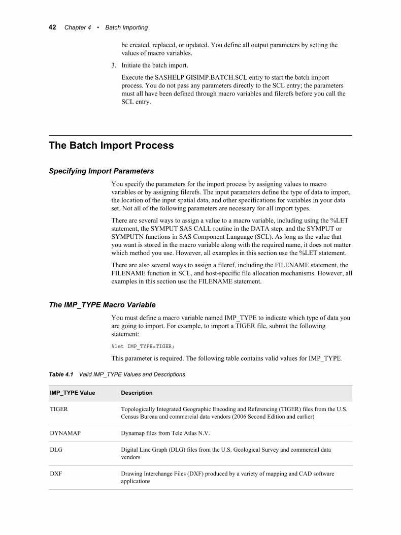
be created, replaced, or updated. You define all output parameters by setting thevalues of macro variables.
3. Initiate the batch import.
Execute the SASHELP.GISIMP.BATCH.SCL entry to start the batch importprocess. You do not pass any parameters directly to the SCL entry; the parametersmust all have been defined through macro variables and filerefs before you call theSCL entry.
The Batch Import Process
Specifying Import ParametersYou specify the parameters for the import process by assigning values to macrovariables or by assigning filerefs. The input parameters define the type of data to import,the location of the input spatial data, and other specifications for variables in your dataset. Not all of the following parameters are necessary for all import types.
There are several ways to assign a value to a macro variable, including using the %LETstatement, the SYMPUT SAS CALL routine in the DATA step, and the SYMPUT orSYMPUTN functions in SAS Component Language (SCL). As long as the value thatyou want is stored in the macro variable along with the required name, it does not matterwhich method you use. However, all examples in this section use the %LET statement.
There are also several ways to assign a fileref, including the FILENAME statement, theFILENAME function in SCL, and host-specific file allocation mechanisms. However, allexamples in this section use the FILENAME statement.
The IMP_TYPE Macro VariableYou must define a macro variable named IMP_TYPE to indicate which type of data youare going to import. For example, to import a TIGER file, submit the followingstatement:
%let IMP_TYPE=TIGER;
This parameter is required. The following table contains valid values for IMP_TYPE.
Table 4.1 Valid IMP_TYPE Values and Descriptions
IMP_TYPE Value Description
TIGER Topologically Integrated Geographic Encoding and Referencing (TIGER) files from the U.S.Census Bureau and commercial data vendors (2006 Second Edition and earlier)
DYNAMAP Dynamap files from Tele Atlas N.V.
DLG Digital Line Graph (DLG) files from the U.S. Geological Survey and commercial datavendors
DXF Drawing Interchange Files (DXF) produced by a variety of mapping and CAD softwareapplications
42 Chapter 4 • Batch Importing
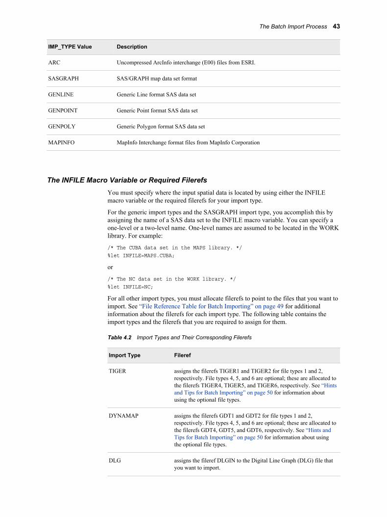
IMP_TYPE Value Description
ARC Uncompressed ArcInfo interchange (E00) files from ESRI.
SASGRAPH SAS/GRAPH map data set format
GENLINE Generic Line format SAS data set
GENPOINT Generic Point format SAS data set
GENPOLY Generic Polygon format SAS data set
MAPINFO MapInfo Interchange format files from MapInfo Corporation
The INFILE Macro Variable or Required FilerefsYou must specify where the input spatial data is located by using either the INFILEmacro variable or the required filerefs for your import type.
For the generic import types and the SASGRAPH import type, you accomplish this byassigning the name of a SAS data set to the INFILE macro variable. You can specify aone-level or a two-level name. One-level names are assumed to be located in the WORKlibrary. For example:
/* The CUBA data set in the MAPS library. */%let INFILE=MAPS.CUBA;
or
/* The NC data set in the WORK library. */%let INFILE=NC;
For all other import types, you must allocate filerefs to point to the files that you want toimport. See “File Reference Table for Batch Importing” on page 49 for additionalinformation about the filerefs for each import type. The following table contains theimport types and the filerefs that you are required to assign for them.
Table 4.2 Import Types and Their Corresponding Filerefs
Import Type Fileref
TIGER assigns the filerefs TIGER1 and TIGER2 for file types 1 and 2,respectively. File types 4, 5, and 6 are optional; these are allocated tothe filerefs TIGER4, TIGER5, and TIGER6, respectively. See “Hintsand Tips for Batch Importing” on page 50 for information aboutusing the optional file types.
DYNAMAP assigns the filerefs GDT1 and GDT2 for file types 1 and 2,respectively. File types 4, 5, and 6 are optional; these are allocated tothe filerefs GDT4, GDT5, and GDT6, respectively. See “Hints andTips for Batch Importing” on page 50 for information about usingthe optional file types.
DLG assigns the fileref DLGIN to the Digital Line Graph (DLG) file thatyou want to import.
The Batch Import Process 43
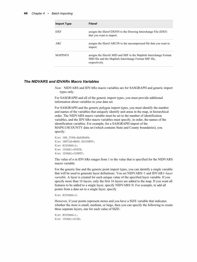
Import Type Fileref
DXF assigns the fileref DXFIN to the Drawing Interchange File (DXF)that you want to import.
ARC assigns the fileref ARCIN to the uncompressed file that you want toimport.
MAPINFO assigns the filerefs MID and MIF to the MapInfo Interchange FormatMID file and the MapInfo Interchange Format MIF file,respectively.
The NIDVARS and IDVARn Macro VariablesNote: NIDVARS and IDVARn macro variables are for SASGRAPH and generic import
types only.
For SASGRAPH and all of the generic import types, you must provide additionalinformation about variables in your data set.
For SASGRAPH and the generic polygon import types, you must identify the numberand names of the variables that uniquely identify unit areas in the map, in hierarchicalorder. The NIDVARS macro variable must be set to the number of identificationvariables, and the IDVARn macro variables must specify, in order, the names of theidentification variables. For example, for a SASGRAPH import of theMAPS.USCOUNTY data set (which contains State and County boundaries), youspecify:
%let IMP_TYPE=SASGRAPH;%let INFILE=MAPS.USCOUNTY;%let NIDVARS=2;%let IDVAR1=STATE;%let IDVAR2=COUNTY;
The value of n in IDVARn ranges from 1 to the value that is specified for the NIDVARSmacro variable.
For the generic line and the generic point import types, you can identify a single variablethat will be used to generate layer definitions. You set NIDVARS=1 and IDVAR1=layervariable. A layer is created for each unique value of the specified layer variable. If youspecify more than 16 layers, only the first 16 layers are added to the map. If you want allfeatures to be added to a single layer, specify NIDVARS=0. For example, to add allpoints from a data set to a single layer, specify
%let NIDVARS=0;
However, if your points represent stores and you have a SIZE variable that indicateswhether the store is small, medium, or large, then you can specify the following to createthree separate layers, one for each value of SIZE:
%let NIDVARS=1;%let IDVAR1=SIZE;
44 Chapter 4 • Batch Importing
The KEEPTEMP Macro VariableDuring a batch import, numerous working data sets are created in the WORK library. Bydefault, these intermediate data sets are deleted when the batch import is complete. Ifyou encounter problems during a batch import, then you might want to retain these datasets to help identify the cause. To prevent the working data sets from being deleted,specify the following:
%let KEEPTEMP=1;
The AREA, CENTROID, and CENTROID_OPT Macro VariablesYou can specify that the batch import calculate the surface area, perimeter, and centroidof the polygons when importing polygonal data. The following list contains descriptionsof the AREA, CENTROID, and CENTROID_OPT macro variables:
AREAspecifies whether to calculate the enclosed areas and perimeter lengths for the areacomposite. Setting the value to 0 indicates that the area and perimeter are not to becalculated. Setting the value to 1 indicates that the area and perimeter are to becalculated. The calculated area is added to the polygonal index data set in a variablenamed AREA. A label for the AREA variable contains the storage area units. Thecalculated perimeter is added to the polygonal index data set in a variable namedPERIMETER. A label for the PERIMETER variable contains the units.
CENTROIDspecifies whether to calculate the centroid of a polygon. Setting the value to 0indicates that centroids are not to be calculated. Setting the value to 1 indicates thatcentroids are to be calculated.
CENTROID_OPTspecifies the type of centroid to be calculated when the CENTROID macro variablehas a value of 1. Setting the value to GEOMETRIC requests the actual calculatedcentroid, which might fall within the boundaries of the corresponding polygon.Setting the value to VISUAL adjusts the centroid so that it falls within theboundaries of the corresponding polygon. The centroid coordinates are added to thepolygonal index data set in variables that are named CTRX and CTRY. Labels forthe CTRX and CTRY variables contain the storage projection units and indicatewhether it is a geometric or visual centroid.
For example, to calculate the area and visual centroids, specify the following:
%let AREA=1;%let CENTROID=1;%let CENTROID_OPT=VISUAL;
Note: The area, perimeter, and centroids are not calculated unless these macro variablesare defined. Once defined, these variables will be used by the batch import processuntil reset in the current SAS session.
Specifying the Output ParametersThe output parameters define the locations where the output data sets and catalog entriesare stored and whether they will be created, replaced, or updated. These parameters arerequired for all import types. The following table contains the macro variables and adescription of the information that each specifies.
The Batch Import Process 45
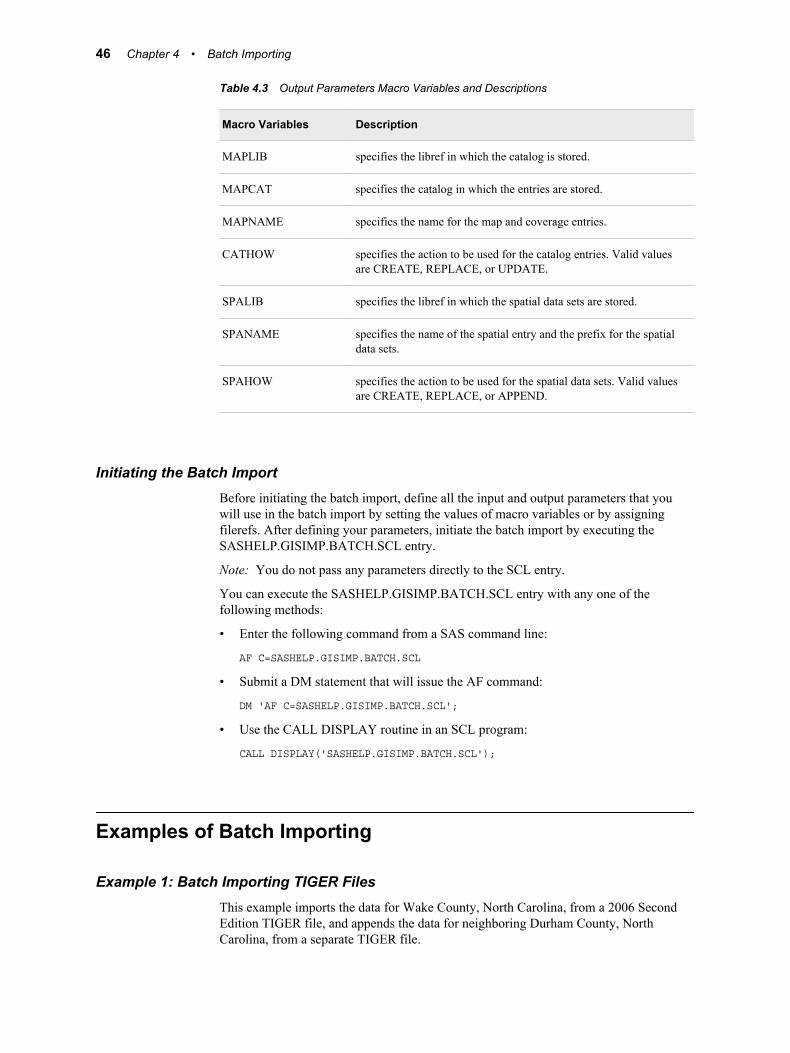
Table 4.3 Output Parameters Macro Variables and Descriptions
Macro Variables Description
MAPLIB specifies the libref in which the catalog is stored.
MAPCAT specifies the catalog in which the entries are stored.
MAPNAME specifies the name for the map and coverage entries.
CATHOW specifies the action to be used for the catalog entries. Valid valuesare CREATE, REPLACE, or UPDATE.
SPALIB specifies the libref in which the spatial data sets are stored.
SPANAME specifies the name of the spatial entry and the prefix for the spatialdata sets.
SPAHOW specifies the action to be used for the spatial data sets. Valid valuesare CREATE, REPLACE, or APPEND.
Initiating the Batch ImportBefore initiating the batch import, define all the input and output parameters that youwill use in the batch import by setting the values of macro variables or by assigningfilerefs. After defining your parameters, initiate the batch import by executing theSASHELP.GISIMP.BATCH.SCL entry.
Note: You do not pass any parameters directly to the SCL entry.
You can execute the SASHELP.GISIMP.BATCH.SCL entry with any one of thefollowing methods:
• Enter the following command from a SAS command line:
AF C=SASHELP.GISIMP.BATCH.SCL
• Submit a DM statement that will issue the AF command:
DM 'AF C=SASHELP.GISIMP.BATCH.SCL';
• Use the CALL DISPLAY routine in an SCL program:
CALL DISPLAY('SASHELP.GISIMP.BATCH.SCL');
Examples of Batch Importing
Example 1: Batch Importing TIGER FilesThis example imports the data for Wake County, North Carolina, from a 2006 SecondEdition TIGER file, and appends the data for neighboring Durham County, NorthCarolina, from a separate TIGER file.
46 Chapter 4 • Batch Importing
/* Define the input parameters for Wake County, North Carolina. */
/* Define the import type. */ %let IMP_TYPE = TIGER;
/* Specify the complete path to the TIGER files for Wake County which were downloaded and unzipped using the required TIGER1 and TIGER2 filerefs. */ filename TIGER1 'tgr37183.rt1'; filename TIGER2 'tgr37183.rt2';
/* Define the output parameters for Wake County, North Carolina. */ %let MAPLIB = SASUSER; %let MAPCAT = TIGER; %let MAPNAME = COUNTIES; %let CATHOW = CREATE; %let SPALIB = SASUSER; %let SPANAME = COUNTIES; %let SPAHOW = CREATE;
/* Initiate the batch import by executing the SCL entry. */ DM 'AF C=SASHELP.GISIMP.BATCH.SCL';
/* Define the input parameters for Durham County, North Carolina. */
/* IMP_TYPE value stays the same, so you just need to reallocate the filerefs to point to the spatial data that was downloaded and unzipped for Durham County. */ filename TIGER1 'tgr37063.rt1'; filename TIGER2 'tgr37063.rt2';
/* Define the output parameters for Durham County, North Carolina. */
/* The locations will stay the same, so you only need to redefine CATHOW and SPAHOW to update the catalog entries and append the spatial data sets for the second import. */ %let CATHOW = UPDATE; %let SPAHOW = APPEND;
/* Initiate the batch import by executing the SCL entry a second time; this time to add the Durham County data to the Wake County data. */ DM 'AF C=SASHELP.GISIMP.BATCH.SCL';
When the import completes, you can open the map namedSASUSER.TIGER.COUNTIES. This map displays Wake and Durham counties.
Examples of Batch Importing 47
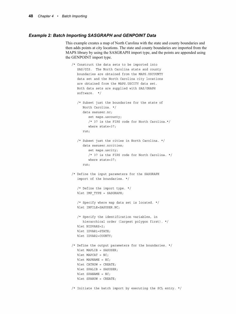
Example 2: Batch Importing SASGRAPH and GENPOINT DataThis example creates a map of North Carolina with the state and county boundaries andthen adds points at city locations. The state and county boundaries are imported from theMAPS library by using the SASGRAPH import type, and the points are appended usingthe GENPOINT import type.
/* Construct the data sets to be imported into SAS/GIS. The North Carolina state and county boundaries are obtained from the MAPS.USCOUNTY data set and the North Carolina city locations are obtained from the MAPS.USCITY data set. Both data sets are supplied with SAS/GRAPH software. */
/* Subset just the boundaries for the state of North Carolina. */ data sasuser.nc; set maps.uscounty; /* 37 is the FIPS code for North Carolina.*/ where state=37; run;
/* Subset just the cities in North Carolina. */ data sasuser.nccities; set maps.uscity; /* 37 is the FIPS code for North Carolina. */ where state=37; run;
/* Define the input parameters for the SASGRAPH import of the boundaries. */
/* Define the import type. */ %let IMP_TYPE = SASGRAPH;
/* Specify where map data set is located. */ %let INFILE=SASUSER.NC;
/* Specify the identification variables, in hierarchical order (largest polygon first). */ %let NIDVARS=2; %let IDVAR1=STATE; %let IDVAR2=COUNTY;
/* Define the output parameters for the boundaries. */ %let MAPLIB = SASUSER; %let MAPCAT = NC; %let MAPNAME = NC; %let CATHOW = CREATE; %let SPALIB = SASUSER; %let SPANAME = NC; %let SPAHOW = CREATE;
/* Initiate the batch import by executing the SCL entry. */
48 Chapter 4 • Batch Importing
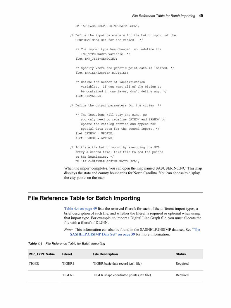
DM 'AF C=SASHELP.GISIMP.BATCH.SCL';
/* Define the input parameters for the batch import of the GENPOINT data set for the cities. */
/* The import type has changed, so redefine the IMP_TYPE macro variable. */ %let IMP_TYPE=GENPOINT;
/* Specify where the generic point data is located. */ %let INFILE=SASUSER.NCCITIES;
/* Define the number of identification variables. If you want all of the cities to be contained in one layer, don't define any. */ %let NIDVARS=0;
/* Define the output parameters for the cities. */
/* The locations will stay the same, so you only need to redefine CATHOW and SPAHOW to update the catalog entries and append the spatial data sets for the second import. */ %let CATHOW = UPDATE; %let SPAHOW = APPEND;
/* Initiate the batch import by executing the SCL entry a second time; this time to add the points to the boundaries. */ DM 'AF C=SASHELP.GISIMP.BATCH.SCL';
When the import completes, you can open the map named SASUSER.NC.NC. This mapdisplays the state and county boundaries for North Carolina. You can choose to displaythe city points on the map.
File Reference Table for Batch ImportingTable 4.4 on page 49 lists the reserved filerefs for each of the different import types, abrief description of each file, and whether the fileref is required or optional when usingthat import type. For example, to import a Digital Line Graph file, you must allocate thefile with a fileref of DLGIN.
Note: This information can also be found in the SASHELP.GISIMP data set. See “TheSASHELP.GISIMP Data Set” on page 39 for more information.
Table 4.4 File Reference Table for Batch Importing
IMP_TYPE Value Fileref File Description Status
TIGER TIGER1 TIGER basic data record (.rt1 file) Required
TIGER2 TIGER shape coordinate points (.rt2 file) Required
File Reference Table for Batch Importing 49
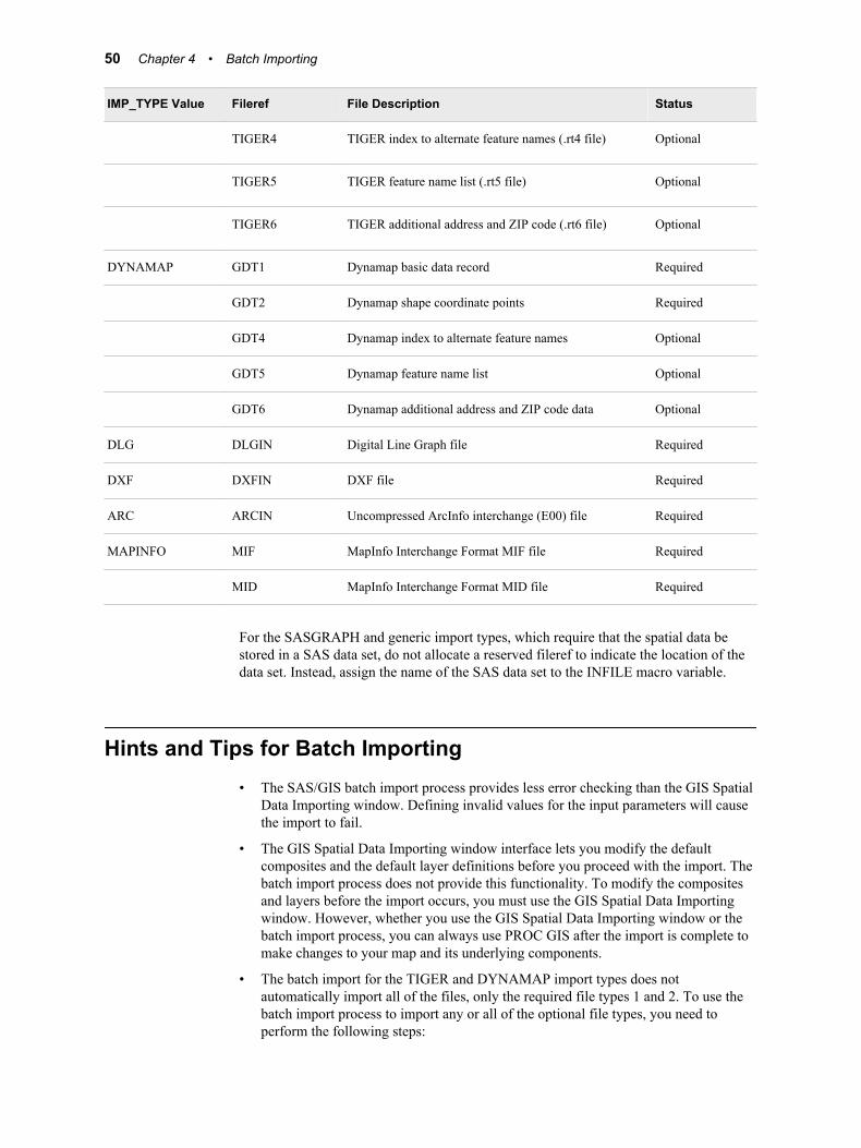
IMP_TYPE Value Fileref File Description Status
TIGER4 TIGER index to alternate feature names (.rt4 file) Optional
TIGER5 TIGER feature name list (.rt5 file) Optional
TIGER6 TIGER additional address and ZIP code (.rt6 file) Optional
DYNAMAP GDT1 Dynamap basic data record Required
GDT2 Dynamap shape coordinate points Required
GDT4 Dynamap index to alternate feature names Optional
GDT5 Dynamap feature name list Optional
GDT6 Dynamap additional address and ZIP code data Optional
DLG DLGIN Digital Line Graph file Required
DXF DXFIN DXF file Required
ARC ARCIN Uncompressed ArcInfo interchange (E00) file Required
MAPINFO MIF MapInfo Interchange Format MIF file Required
MID MapInfo Interchange Format MID file Required
For the SASGRAPH and generic import types, which require that the spatial data bestored in a SAS data set, do not allocate a reserved fileref to indicate the location of thedata set. Instead, assign the name of the SAS data set to the INFILE macro variable.
Hints and Tips for Batch Importing• The SAS/GIS batch import process provides less error checking than the GIS Spatial
Data Importing window. Defining invalid values for the input parameters will causethe import to fail.
• The GIS Spatial Data Importing window interface lets you modify the defaultcomposites and the default layer definitions before you proceed with the import. Thebatch import process does not provide this functionality. To modify the compositesand layers before the import occurs, you must use the GIS Spatial Data Importingwindow. However, whether you use the GIS Spatial Data Importing window or thebatch import process, you can always use PROC GIS after the import is complete tomake changes to your map and its underlying components.
• The batch import for the TIGER and DYNAMAP import types does notautomatically import all of the files, only the required file types 1 and 2. To use thebatch import process to import any or all of the optional file types, you need toperform the following steps:
50 Chapter 4 • Batch Importing
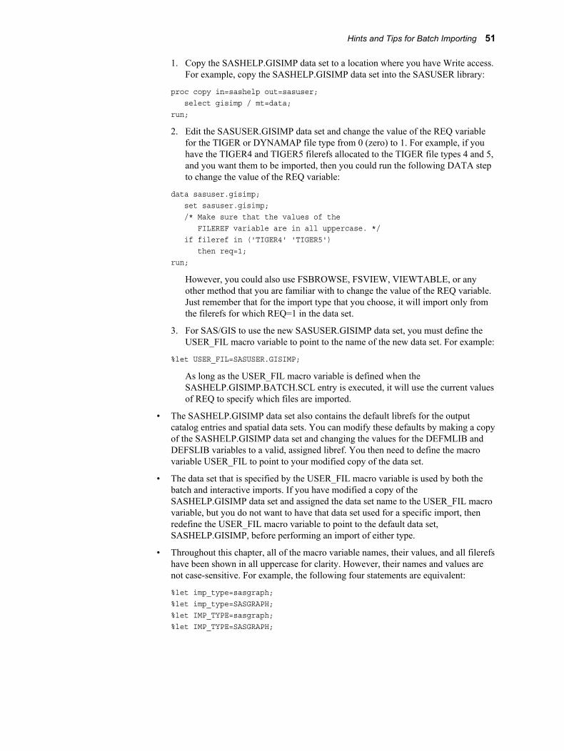
1. Copy the SASHELP.GISIMP data set to a location where you have Write access.For example, copy the SASHELP.GISIMP data set into the SASUSER library:
proc copy in=sashelp out=sasuser; select gisimp / mt=data;run;
2. Edit the SASUSER.GISIMP data set and change the value of the REQ variablefor the TIGER or DYNAMAP file type from 0 (zero) to 1. For example, if youhave the TIGER4 and TIGER5 filerefs allocated to the TIGER file types 4 and 5,and you want them to be imported, then you could run the following DATA stepto change the value of the REQ variable:
data sasuser.gisimp; set sasuser.gisimp; /* Make sure that the values of the FILEREF variable are in all uppercase. */ if fileref in ('TIGER4' 'TIGER5') then req=1;run;
However, you could also use FSBROWSE, FSVIEW, VIEWTABLE, or anyother method that you are familiar with to change the value of the REQ variable.Just remember that for the import type that you choose, it will import only fromthe filerefs for which REQ=1 in the data set.
3. For SAS/GIS to use the new SASUSER.GISIMP data set, you must define theUSER_FIL macro variable to point to the name of the new data set. For example:
%let USER_FIL=SASUSER.GISIMP;
As long as the USER_FIL macro variable is defined when theSASHELP.GISIMP.BATCH.SCL entry is executed, it will use the current valuesof REQ to specify which files are imported.
• The SASHELP.GISIMP data set also contains the default librefs for the outputcatalog entries and spatial data sets. You can modify these defaults by making a copyof the SASHELP.GISIMP data set and changing the values for the DEFMLIB andDEFSLIB variables to a valid, assigned libref. You then need to define the macrovariable USER_FIL to point to your modified copy of the data set.
• The data set that is specified by the USER_FIL macro variable is used by both thebatch and interactive imports. If you have modified a copy of theSASHELP.GISIMP data set and assigned the data set name to the USER_FIL macrovariable, but you do not want to have that data set used for a specific import, thenredefine the USER_FIL macro variable to point to the default data set,SASHELP.GISIMP, before performing an import of either type.
• Throughout this chapter, all of the macro variable names, their values, and all filerefshave been shown in all uppercase for clarity. However, their names and values arenot case-sensitive. For example, the following four statements are equivalent:
%let imp_type=sasgraph;%let imp_type=SASGRAPH;%let IMP_TYPE=sasgraph;%let IMP_TYPE=SASGRAPH;
Hints and Tips for Batch Importing 51

52 Chapter 4 • Batch Importing
Chapter 5
Working with Spatial Data
SAS/GIS Data Sets . . . . . . . . . . . . . . . . . . . . . . . . . . . . . . . . . . . . . . . . . . . . . . . . . . . . 53SAS Data Sets . . . . . . . . . . . . . . . . . . . . . . . . . . . . . . . . . . . . . . . . . . . . . . . . . . . . . . 53Chains Data Set . . . . . . . . . . . . . . . . . . . . . . . . . . . . . . . . . . . . . . . . . . . . . . . . . . . . . 54Nodes Data Set . . . . . . . . . . . . . . . . . . . . . . . . . . . . . . . . . . . . . . . . . . . . . . . . . . . . . 54Details Data Set . . . . . . . . . . . . . . . . . . . . . . . . . . . . . . . . . . . . . . . . . . . . . . . . . . . . 55Polygonal Index Data Sets . . . . . . . . . . . . . . . . . . . . . . . . . . . . . . . . . . . . . . . . . . . . 55Label Data Set . . . . . . . . . . . . . . . . . . . . . . . . . . . . . . . . . . . . . . . . . . . . . . . . . . . . . . 55Attribute Data Sets . . . . . . . . . . . . . . . . . . . . . . . . . . . . . . . . . . . . . . . . . . . . . . . . . . 55Managing Data Set Sizes . . . . . . . . . . . . . . . . . . . . . . . . . . . . . . . . . . . . . . . . . . . . . 55Import Type Specific Variables . . . . . . . . . . . . . . . . . . . . . . . . . . . . . . . . . . . . . . . . 56
Data Set and Catalog Entry Interactions . . . . . . . . . . . . . . . . . . . . . . . . . . . . . . . . . . 61Catalog Entry Types Used by SAS/GIS . . . . . . . . . . . . . . . . . . . . . . . . . . . . . . . . . . 61Spatial Entries . . . . . . . . . . . . . . . . . . . . . . . . . . . . . . . . . . . . . . . . . . . . . . . . . . . . . . 62Coverage Entries . . . . . . . . . . . . . . . . . . . . . . . . . . . . . . . . . . . . . . . . . . . . . . . . . . . . 63Layer Entries . . . . . . . . . . . . . . . . . . . . . . . . . . . . . . . . . . . . . . . . . . . . . . . . . . . . . . . 64Map Entries . . . . . . . . . . . . . . . . . . . . . . . . . . . . . . . . . . . . . . . . . . . . . . . . . . . . . . . . 65Composites . . . . . . . . . . . . . . . . . . . . . . . . . . . . . . . . . . . . . . . . . . . . . . . . . . . . . . . . 65
Merging Spatial Data with the MERGE= Argument . . . . . . . . . . . . . . . . . . . . . . . . 66Overview . . . . . . . . . . . . . . . . . . . . . . . . . . . . . . . . . . . . . . . . . . . . . . . . . . . . . . . . . . 66Types of Merge Operations . . . . . . . . . . . . . . . . . . . . . . . . . . . . . . . . . . . . . . . . . . . 66Benefits of Merging Data . . . . . . . . . . . . . . . . . . . . . . . . . . . . . . . . . . . . . . . . . . . . . 67
Sample SAS/GIS Spatial Database . . . . . . . . . . . . . . . . . . . . . . . . . . . . . . . . . . . . . . . 67
Hints and Tips for Working with Spatial Data . . . . . . . . . . . . . . . . . . . . . . . . . . . . . 67
SAS/GIS Data Sets
SAS Data SetsA SAS data set is a collection of data values and their associated descriptive informationthat is arranged and presented in a form that can be recognized and processed by SAS.SAS data sets can be data files or views. A SAS data file contains the followingelements:
• data values that are organized into a rectangular structure of columns and rows
• descriptor information that identifies attributes of both the data set and the datavalues
53
A SAS view contains the following elements:
• instructions to build a table
• descriptor information that identifies attributes of both the data set and the datavalues
SAS data sets can be indexed by one or more variables, known as key variables. A SASindex contains the data values of the key variables that are paired with locationidentifiers for the observations that contain the variables. The value and identifier pairsare ordered in a B-tree structure that enables the engine to search by value. SAS indexesare classified as simple or composite, according to the number of key variables that theycontain.
For more information about SAS data sets, SAS files, SAS views, and SAS indexes,refer to SAS Language Reference: Concepts.
As a component of SAS, SAS/GIS stores all of its data in SAS data sets. The SAS/GISspatial database works as one logical entity, but is physically separated into six differentcategories of data sets:
• chains
• nodes
• details
• polygonal index
• label
• attribute
A given SAS/GIS map can reference only one chains, nodes, details, and label data set,but it can reference multiple polygonal index and attribute data sets. Multiple SAS/GISmaps can use a single set of chains, nodes, and details data sets.
Chains Data SetThe chains data set contains coordinates for the polylines that are used to form line andpolygon features. A polyline consists of a series of connected line segments that arechains. A chain is a sequence of two or more points in the coordinate space. The endpoints, the first and last points of the chain, must be nodes. Each chain has a direction,from the first point toward the last point. The first point in the chain is the from-node,and the last point is the o-node. Relative to its direction, a chain has a left side and aright side. Points between the from-node and the to-node are detail points, which serveto trace the curvature of the feature that is represented by the chain. Detail points are notnodes.
The chains data set also lists the from-node and to-node row numbers in the nodes dataset, as well as the number of detail points and the corresponding details data set rownumber. The left and right side attribute values (for example, ZIP codes and FIPS codes)are also stored in the chains data set.
Nodes Data SetThe nodes data set contains the coordinates of the end points for the chains in the chainsdata set and the linkage information that is necessary to attach chains to the correctnodes. A node is a point in the spatial data with connections to one or more chains.Nodes can be discrete points or the end points of chains. A node definition can span
54 Chapter 5 • Working with Spatial Data
multiple records in the nodes data set, so only the starting record number for a node is anode feature ID.
Details Data SetThe details data set stores the curvature points of a chain between the two end nodes,which are also called the from-node and the to-node. That is, the details data set containsall the coordinates between the intersection points of the chain. The node coordinates arenot duplicated in the details data set. The details data set also contains the chains data setrow number of the associated chain.
Polygonal Index Data SetsThe polygonal index data set contains one observation for each polygon that wassuccessfully closed during the index creation process. It is called a polygonal indexbecause each observation is an index to a polygon in the chains data set. That is, it pointsto the starting chain in the chains data set for each of the polygons.
If polygon areas, perimeter distances, and centroid locations were computed, then thatinformation is also stored in the polygonal index data set.
Label Data SetThe label data set defines the attributes of labels to be displayed on the map. Theattributes include all of the information that is applicable for each label, such as location,color, size, source of the text for a text label, as well as other behavioral and graphicalattributes.
Attribute Data SetsAttribute data sets contain values related to the map features. The observations inattribute data sets must be associated with observations in the chains data set. Attributedata is used to display themes on the map and for spatially oriented reports, graphs, mapactions, and so on.
Managing Data Set SizesBy their nature, spatial databases tend to be rather large. Users of spatial data want asmuch detail in the maps as they can get, which increases the demands on storage andprocessing capacity. Spatial data that is not carefully managed can become too large foreasy use.
Here are five actions that you can take to manage the size of your spatial data sets. Youneed to perform most of these actions before importing your data into SAS/GIS.
• Reduce the spatial extent of the data.
Do not store a larger area than you need. If you need a map containing one state, donot store a map containing all the states for a region. For example, if you need towork with a map of Oregon, do not store a map containing all of the PacificNorthwest.
• Store only the features that you need.
If you do not need features such as rivers and lakes, do not store these features inyour spatial data.
SAS/GIS Data Sets 55
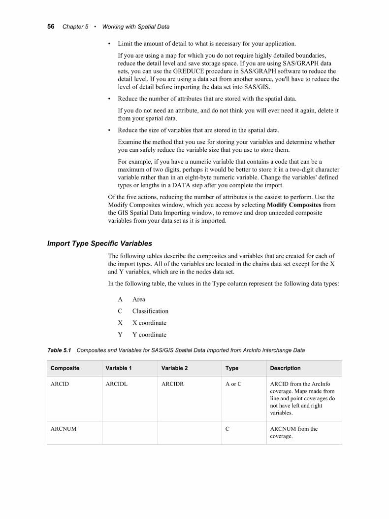
• Limit the amount of detail to what is necessary for your application.
If you are using a map for which you do not require highly detailed boundaries,reduce the detail level and save storage space. If you are using SAS/GRAPH datasets, you can use the GREDUCE procedure in SAS/GRAPH software to reduce thedetail level. If you are using a data set from another source, you'll have to reduce thelevel of detail before importing the data set into SAS/GIS.
• Reduce the number of attributes that are stored with the spatial data.
If you do not need an attribute, and do not think you will ever need it again, delete itfrom your spatial data.
• Reduce the size of variables that are stored in the spatial data.
Examine the method that you use for storing your variables and determine whetheryou can safely reduce the variable size that you use to store them.
For example, if you have a numeric variable that contains a code that can be amaximum of two digits, perhaps it would be better to store it in a two-digit charactervariable rather than in an eight-byte numeric variable. Change the variables' definedtypes or lengths in a DATA step after you complete the import.
Of the five actions, reducing the number of attributes is the easiest to perform. Use theModify Composites window, which you access by selecting Modify Composites fromthe GIS Spatial Data Importing window, to remove and drop unneeded compositevariables from your data set as it is imported.
Import Type Specific VariablesThe following tables describe the composites and variables that are created for each ofthe import types. All of the variables are located in the chains data set except for the Xand Y variables, which are in the nodes data set.
In the following table, the values in the Type column represent the following data types:
A Area
C Classification
X X coordinate
Y Y coordinate
Table 5.1 Composites and Variables for SAS/GIS Spatial Data Imported from ArcInfo Interchange Data
Composite Variable 1 Variable 2 Type Description
ARCID ARCIDL ARCIDR A or C ARCID from the ArcInfocoverage. Maps made fromline and point coverages donot have left and rightvariables.
ARCNUM C ARCNUM from thecoverage.
56 Chapter 5 • Working with Spatial Data
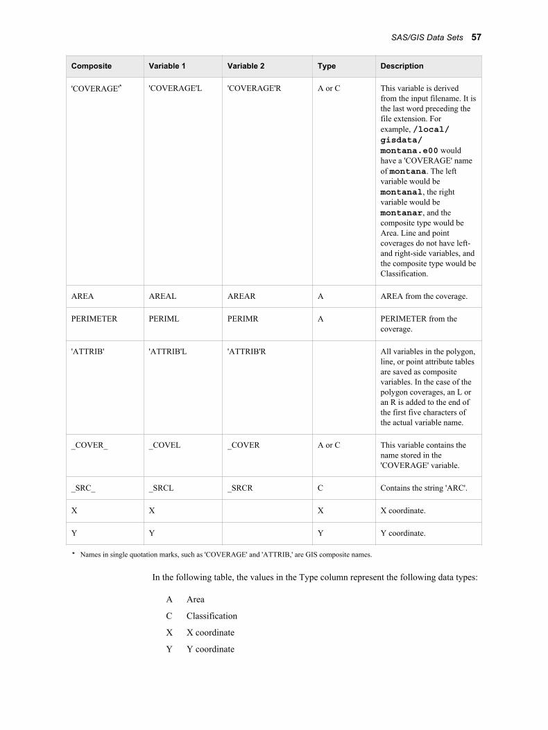
Composite Variable 1 Variable 2 Type Description
'COVERAGE'* 'COVERAGE'L 'COVERAGE'R A or C This variable is derivedfrom the input filename. It isthe last word preceding thefile extension. Forexample, /local/gisdata/montana.e00 wouldhave a 'COVERAGE' nameof montana. The leftvariable would bemontanal, the rightvariable would bemontanar, and thecomposite type would beArea. Line and pointcoverages do not have left-and right-side variables, andthe composite type would beClassification.
AREA AREAL AREAR A AREA from the coverage.
PERIMETER PERIML PERIMR A PERIMETER from thecoverage.
'ATTRIB' 'ATTRIB'L 'ATTRIB'R All variables in the polygon,line, or point attribute tablesare saved as compositevariables. In the case of thepolygon coverages, an L oran R is added to the end ofthe first five characters ofthe actual variable name.
_COVER_ _COVEL _COVER A or C This variable contains thename stored in the'COVERAGE' variable.
_SRC_ _SRCL _SRCR C Contains the string 'ARC'.
X X X X coordinate.
Y Y Y Y coordinate.
* Names in single quotation marks, such as 'COVERAGE' and 'ATTRIB,' are GIS composite names.
In the following table, the values in the Type column represent the following data types:
A Area
C Classification
X X coordinate
Y Y coordinate
SAS/GIS Data Sets 57
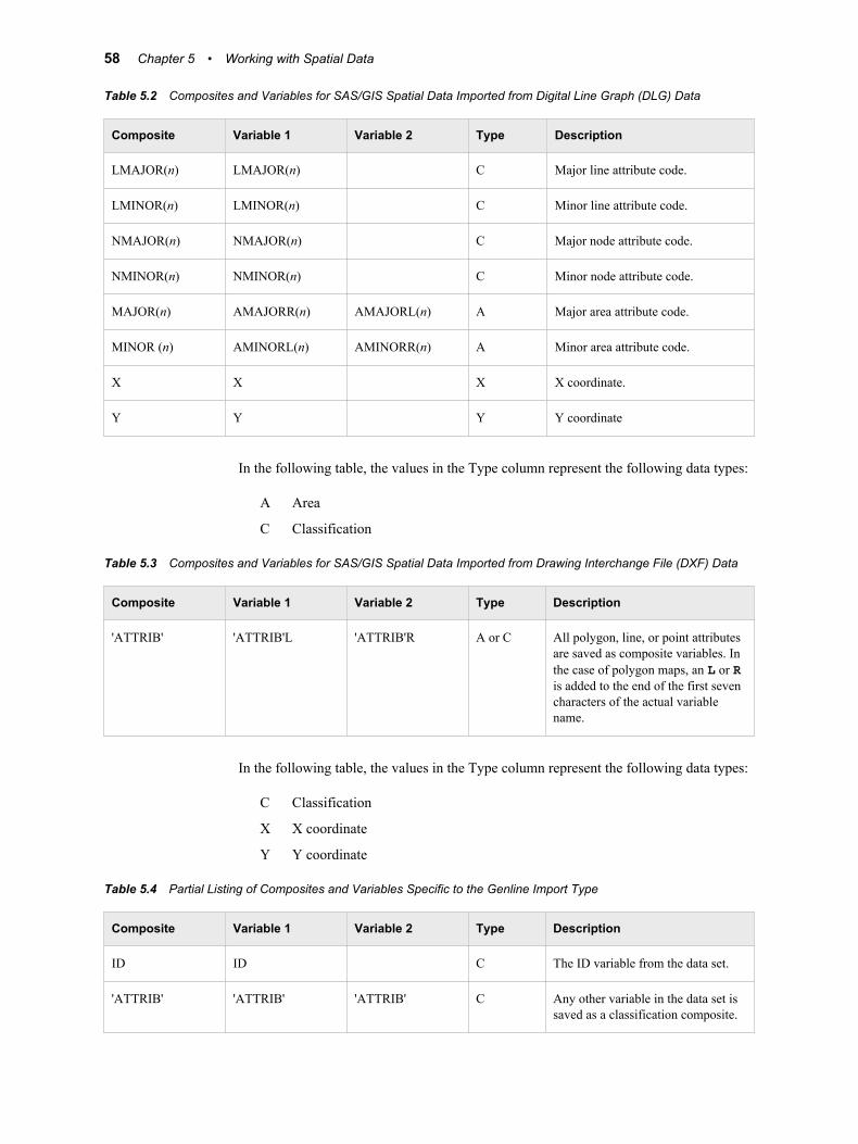
Table 5.2 Composites and Variables for SAS/GIS Spatial Data Imported from Digital Line Graph (DLG) Data
Composite Variable 1 Variable 2 Type Description
LMAJOR(n) LMAJOR(n) C Major line attribute code.
LMINOR(n) LMINOR(n) C Minor line attribute code.
NMAJOR(n) NMAJOR(n) C Major node attribute code.
NMINOR(n) NMINOR(n) C Minor node attribute code.
MAJOR(n) AMAJORR(n) AMAJORL(n) A Major area attribute code.
MINOR (n) AMINORL(n) AMINORR(n) A Minor area attribute code.
X X X X coordinate.
Y Y Y Y coordinate
In the following table, the values in the Type column represent the following data types:
A Area
C Classification
Table 5.3 Composites and Variables for SAS/GIS Spatial Data Imported from Drawing Interchange File (DXF) Data
Composite Variable 1 Variable 2 Type Description
'ATTRIB' 'ATTRIB'L 'ATTRIB'R A or C All polygon, line, or point attributesare saved as composite variables. Inthe case of polygon maps, an L or Ris added to the end of the first sevencharacters of the actual variablename.
In the following table, the values in the Type column represent the following data types:
C Classification
X X coordinate
Y Y coordinate
Table 5.4 Partial Listing of Composites and Variables Specific to the Genline Import Type
Composite Variable 1 Variable 2 Type Description
ID ID C The ID variable from the data set.
'ATTRIB' 'ATTRIB' 'ATTRIB' C Any other variable in the data set issaved as a classification composite.
58 Chapter 5 • Working with Spatial Data
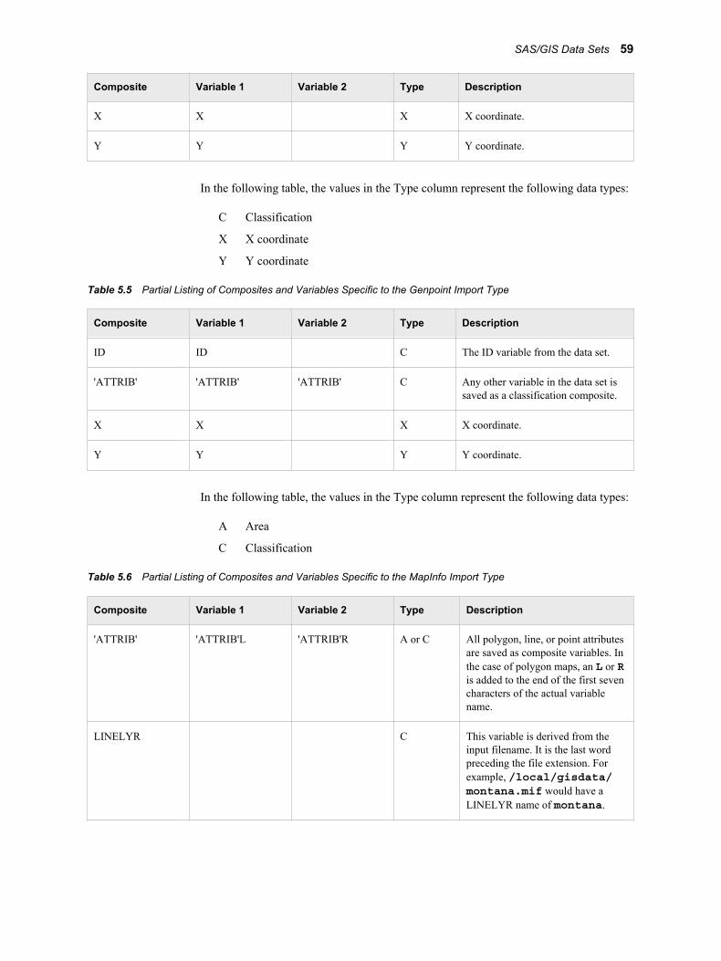
Composite Variable 1 Variable 2 Type Description
X X X X coordinate.
Y Y Y Y coordinate.
In the following table, the values in the Type column represent the following data types:
C Classification
X X coordinate
Y Y coordinate
Table 5.5 Partial Listing of Composites and Variables Specific to the Genpoint Import Type
Composite Variable 1 Variable 2 Type Description
ID ID C The ID variable from the data set.
'ATTRIB' 'ATTRIB' 'ATTRIB' C Any other variable in the data set issaved as a classification composite.
X X X X coordinate.
Y Y Y Y coordinate.
In the following table, the values in the Type column represent the following data types:
A Area
C Classification
Table 5.6 Partial Listing of Composites and Variables Specific to the MapInfo Import Type
Composite Variable 1 Variable 2 Type Description
'ATTRIB' 'ATTRIB'L 'ATTRIB'R A or C All polygon, line, or point attributesare saved as composite variables. Inthe case of polygon maps, an L or Ris added to the end of the first sevencharacters of the actual variablename.
LINELYR C This variable is derived from theinput filename. It is the last wordpreceding the file extension. Forexample, /local/gisdata/montana.mif would have aLINELYR name of montana.
SAS/GIS Data Sets 59
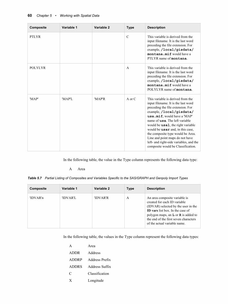
Composite Variable 1 Variable 2 Type Description
PTLYR C This variable is derived from theinput filename. It is the last wordpreceding the file extension. Forexample, /local/gisdata/montana.mif would have aPTLYR name of montana.
POLYLYR A This variable is derived from theinput filename. It is the last wordpreceding the file extension. Forexample, /local/gisdata/montana.mif would have aPOLYLYR name of montana.
'MAP' 'MAP'L 'MAP'R A or C This variable is derived from theinput filename. It is the last wordpreceding the file extension. Forexample, /local/gisdata/usa.mif, would have a 'MAP'name of usa. The left variablewould be usal, the right variablewould be usar and, in this case,the composite type would be Area.Line and point maps do not haveleft- and right-side variables, and thecomposite would be Classification.
In the following table, the value in the Type column represents the following data type:
A Area
Table 5.7 Partial Listing of Composites and Variables Specific to the SAS/GRAPH and Genpoly Import Types
Composite Variable 1 Variable 2 Type Description
'IDVAR'n 'IDVAR'L 'IDVAR'R A An area composite variable iscreated for each ID variable(IDVAR) selected by the user in theID vars list box. In the case ofpolygon maps, an L or R is added tothe end of the first seven charactersof the actual variable name.
In the following table, the values in the Type column represent the following data types:
A Area
ADDR Address
ADDRP Address Prefix
ADDRS Address Suffix
C Classification
X Longitude
60 Chapter 5 • Working with Spatial Data
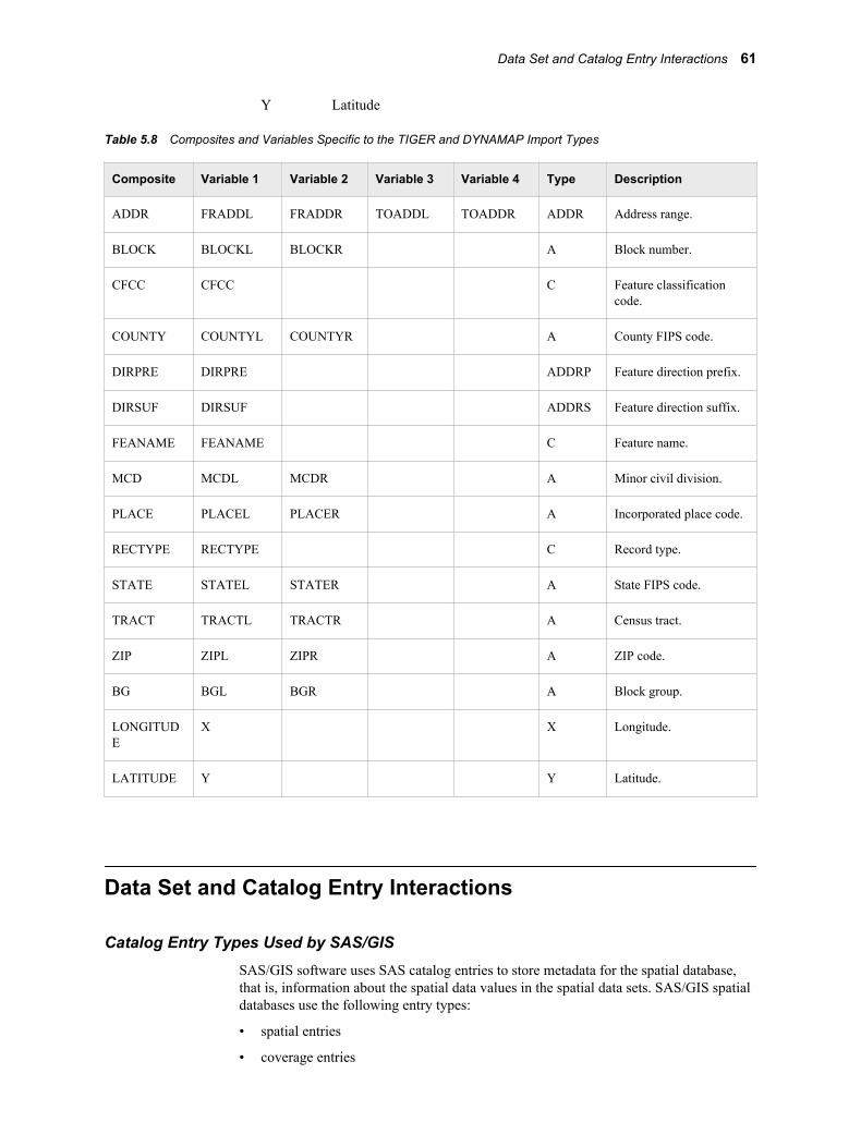
Y Latitude
Table 5.8 Composites and Variables Specific to the TIGER and DYNAMAP Import Types
Composite Variable 1 Variable 2 Variable 3 Variable 4 Type Description
ADDR FRADDL FRADDR TOADDL TOADDR ADDR Address range.
BLOCK BLOCKL BLOCKR A Block number.
CFCC CFCC C Feature classificationcode.
COUNTY COUNTYL COUNTYR A County FIPS code.
DIRPRE DIRPRE ADDRP Feature direction prefix.
DIRSUF DIRSUF ADDRS Feature direction suffix.
FEANAME FEANAME C Feature name.
MCD MCDL MCDR A Minor civil division.
PLACE PLACEL PLACER A Incorporated place code.
RECTYPE RECTYPE C Record type.
STATE STATEL STATER A State FIPS code.
TRACT TRACTL TRACTR A Census tract.
ZIP ZIPL ZIPR A ZIP code.
BG BGL BGR A Block group.
LONGITUDE
X X Longitude.
LATITUDE Y Y Latitude.
Data Set and Catalog Entry Interactions
Catalog Entry Types Used by SAS/GISSAS/GIS software uses SAS catalog entries to store metadata for the spatial database,that is, information about the spatial data values in the spatial data sets. SAS/GIS spatialdatabases use the following entry types:
• spatial entries
• coverage entries
Data Set and Catalog Entry Interactions 61
• layer entries
• map entries
• composites
Spatial Entries
OverviewA spatial entry is a SAS catalog entry of type GISSPA that identifies the spatial data setsfor a given spatial database and defines relationships between the variables in those datasets.
Spatial entries are created and modified using the SPATIAL statement in the GISprocedure.
Note: You can also create a new spatial entry by selecting the following from the GISMap window's menu bar:File ð Save As ð Spatial
SAS/GIS software supports simple spatial entries and merged spatial entries.
Simple Spatial EntriesSimple spatial entries contain the following elements:
• references to the chains, nodes, and details data sets that contain spatial information.
• references to any polygonal index data sets that define the boundaries of areafeatures in the spatial data.
• definitions for composites that specify how the variables in the spatial data sets areused. See “Composites” on page 65 for more information about composites.
• the definition for a lattice hierarchy that specifies which area features in the spatialdata enclose or are enclosed by other features.
• parameters for the projection system that is used to interpret the spatial informationthat is stored in the spatial data sets.
• the accumulated bounding extents of the spatial data coordinates of its underlyingchild spatial data sets, consisting of the minimum and maximum X and Y coordinatevalues and the ranges of X and Y values.
Merged Spatial EntriesMerged spatial entries have the following attributes:
• consist of multiple SAS/GIS spatial databases that are linked together hierarchicallyin a tree structure.
• contain logical references to two or more child spatial entries. A child spatial entry isa dependent spatial entry beneath the merged spatial entry in the hierarchy.
• contain specifications of how the entries were merged (by overlapping or edgematching).
• do not have their own spatial data sets.
• reference the spatial data sets that belong to the child spatial entries beneath them onthe hierarchy.
• do not have references to any polygonal index data sets that define the boundaries ofarea features in the spatial data.
62 Chapter 5 • Working with Spatial Data
• do not have definitions for composites that specify how the variables in the spatialdata sets are used. See “Composites” on page 65 for more information aboutcomposites.
• do not have the definition for a lattice hierarchy that specifies which area features inthe spatial data enclose or are enclosed by other features.
• do not have parameters for the projection system that is used to interpret the spatialinformation stored in the spatial data sets.
• contain the accumulated bounding extents of the spatial data coordinates of theirunderlying child spatial entries, consisting of the minimum and maximum X and Ycoordinate values and the ranges of X and Y values.
Merged spatial entries can help you to manage your spatial data requirements. Forexample, you might have two spatial databases that contain the county boundaries ofadjoining states. You can build a merged spatial entry that references both states andview a single map that contains both states' counties. Otherwise, you would have toimport a new map containing the two states' counties. This new map would double yourspatial data storage requirements.
The following additional statements in the GIS procedure update the information in thespatial entry:
COMPOSITE statementcreates or modifies composites that define the relation and function of variables inthe spatial data sets. The composite definition is stored in the spatial entry. SeeCOMPOSITE Statement on page 93 for details about creating or modifyingcomposites.
POLYGONAL INDEX statementupdates the list of available index names stored in the spatial entry. SeePOLYGONAL INDEX Statement on page 98 for details about creating andmodifying polygonal indexes.
LATTICE statementupdates the lattice hierarchy stored in the spatial entry. See LATTICE Statement onpage 102 for details about defining lattice hierarchies.
You can view a formatted report of the contents of a spatial entry by submitting aSPATIAL CONTENTS statement in the GIS procedure.
See SPATIAL Statement on page 88 for details about using the GIS procedure tocreate, modify, or view the contents of spatial entries.
Coverage EntriesA coverage entry is a SAS catalog entry of type GISCOVER that defines the subset, orcoverage, of the spatial data that is available to a map. SAS/GIS maps refer to coveragesrather than directly to the spatial data.
A coverage entry contains the following elements:
• a reference to the root spatial entry.
• a WHERE expression that describes the logical subset of the spatial data that isavailable for display in a map.
Note: The expression WHERE='1' can be used to define a coverage that includes allthe data that is in the spatial database. WHERE='1' is called a universal coverage.
The WHERE expression binds the coverage entry to the spatial data sets that itsubsets. The WHERE expression is checked for compatibility with the spatial data
Data Set and Catalog Entry Interactions 63
when the coverage entry is created and also whenever a map that uses the coverageentry is opened.
• the maximum and minimum X and Y coordinates in the portion of the spatial datathat meets the WHERE expression criteria for the coverage.
These maximum and minimum coordinates are evaluated when the coverage iscreated. The GIS procedure's COVERAGE CREATE statement reads the matchingchains and determines the extents from the chains' XMIN, YMIN, XMAX, andYMAX variables. If you make changes to the chains, nodes, and details data sets thataffect the coverage extents, use the COVERAGE UPDATE statement to update thebounding extent values.
Multiple coverage entries can refer to the same spatial entry to create different subsets ofthe spatial data for different maps. For example, you could define a series of coveragesto subset a county into multiple sales regions according to the block groups that arecontained in each of the regions. The spatial data for the entire county would still be in asingle spatial database that is represented by the chains, nodes, and details data sets andby the controlling spatial entry.
Coverage entries are created and modified by using the COVERAGE statement in theGIS procedure. You can view a formatted report of the contents of a coverage entry bysubmitting a COVERAGE CONTENTS statement in the GIS procedure. (The contentsreport for a coverage entry also includes all the contents information for the root spatialentry as well.)
See COVERAGE Statement on page 104 for more information about creating,modifying, or viewing the contents of coverage entries.
Layer EntriesA layer entry is a SAS catalog entry of type GISLAYER that defines the set of featuresthat compose a layer in the map. A layer entry contains the following elements:
• a WHERE expression that describes the common characteristic of features in thelayer.
The WHERE expression binds the layer entry to the spatial data even though theWHERE expression is stored in the layer entry. The layer is not bound to a specificspatial entry, just to those entries that represent the same type of data. Therefore, alayer that is created for use with data that is imported from a TIGER file can be usedwith data that is imported from any TIGER file. However, not all file types can takeadvantage of this behavior. The WHERE expression is checked for compatibilitywith spatial data when the layer entry is created and also whenever a map that usesthe layer entry is opened.
Note: When you define area layers, you can specify a composite as an alternative tospecifying an explicit WHERE expression. However, the layer entry stores theWHERE expression that is implied by the composite. For example, if you specifySTATE as the defining composite for a layer, and the STATE compositespecifies the following variables: VAR=(LEFT=STATEL,RIGHT=STATER),then the implied WHERE expression that is stored in the layer entry is 'STATELNE STATER'.
• option settings for the layer such as the layer type (point, line, or area), whether thelayer is static or thematic, whether it is initially displayed or hidden, whether detailpoints are drawn for the layer, and the scales at which the layer is automaticallyturned on or off.
64 Chapter 5 • Working with Spatial Data
• the graphical attributes that are necessary to draw the layer when it is displayed as astatic layer.
• the attribute links, theme range breaks, and graphical attributes if the layer containsthemes.
See LAYER Statement on page 107 for more information about creating, modifying, orviewing the contents of layer entries.
Map EntriesA map entry is a SAS catalog entry of type GISMAP. Map entries are the controllingentries for SAS/GIS maps because they tie together all the information that is needed todisplay a map. A map entry contains the following elements:
• a reference to the coverage entry that defines the subset of the spatial data that isavailable to the map. Note that the map entry refers to a particular coverage of thespatial data rather than directly to the spatial entry.
• references to the layer entries for all layers that are included in the map.
• references to any attribute data sets that are associated with the map, for example, thedata sets that are used for the map actions, along with definitions of how the attributedata sets are linked to the spatial data.
• a reference to the SAS data set that contains labels for map features.
• definitions for the actions that can be performed.
• definitions for map legends.
• parameters for the projection system that is used to project the spatial datacoordinates for display.
• option settings for the map, including the following:
• the units and mode for the map scale
• whether coordinate, distance, and attribute feedback are displayed
• whether detail points are read
• whether the tool palette is active.
Map entries are created by using the MAP CREATE statement in the GIS procedure.However, much of the information that is stored in the map entry is specifiedinteractively in the GIS Map window.
You can view a formatted report of the contents of a map entry by submitting a MAPCONTENTS statement in the GIS procedure. (The contents report for a map entryincludes all the contents information for the spatial, coverage, and layer entries as well.)See MAP Statement on page 133 for details about using the MAP statement. SeeChapter 10, “ SAS/GIS Windows” in SAS/GIS Software: Usage and Reference, Version6, for details about the items that can be specified interactively in the GIS Map window.
CompositesFor most operations that involve the spatial database, you refer to composites of thespatial data variables rather than directly to the variables in the spatial data sets. Acomposite consists of the following elements:
• a variable association that identifies which variable or variables in the spatialdatabase comprise the association. The variable association can specify a single
Data Set and Catalog Entry Interactions 65
variable, a pair of variables that define a bilateral (left-right) association, or two pairsof variables that define the start and end of a directional (from-to) bilateralassociation.
• a class attribute that identifies the role of the composite in the spatial database.
For example, if the chains data set has a variable named FEANAME that containsfeature names, you can create a composite for the FEANAME variable that assigns theclass attribute NAME to indicate that the association represents feature names. Or, if thechains data set has COUNTYL and COUNTYR variables that contain the codes for thecounties on the left and right sides of the chains, you can create a composite namedCOUNTY. The composite identifies the bilateral relationship between these twovariables and assigns the class attribute AREA to indicate that the association definescounty areas in the spatial data.
Composites are created and modified using the COMPOSITE statement in the GISprocedure. Composite definitions are stored in the spatial entry. When a spatial action isperformed in a map, the variables referenced by composites for the selected map featuresare displayed in the Spatial Information window. See COMPOSITE Statement on page93 for more information about creating or modifying composites.
Merging Spatial Data with the MERGE= Argument
OverviewMERGE= is an argument of the GIS procedure's SPATIAL statement that enables you tobuild a new spatial entry by referencing two or more existing spatial entries. Thedependent data sets for the spatial entries are not actually combined when you use theMERGE= argument; the new spatial entry includes them by reference. For moreinformation about the syntax for the MERGE= option, see SPATIAL Statement on page88.
Note: Keep in mind that MERGE is specified as an option on a SPATIAL statement.
If you specify a one-level name for any of the entries to be merged, the spatial entry isassumed to be in the catalog that is specified in the CATALOG= argument with thePROC GIS statement or in the most recently issued CATALOG statement. An erroroccurs if you have not specified a catalog before specifying the names of the entries thatyou want to merge.
Types of Merge OperationsThe MERGE= argument accepts the following arguments:
EDGEMATCHlocates common boundaries between the merged spatial entries and updates missingleft- or right-side composite variable values in the chains data that lie on theboundaries.
In other words, the EDGEMATCH operation compares the chains in the differentdata sets and finds those chains that map the same feature. When it finds the samechain in both data sets, it replaces any missing left- or right-side composite values ineither chain with the valid values from the other data set. EDGEMATCH also createsa merged spatial entry that references other spatial entries (either merged or simple)that you specified with the MERGE= argument.
66 Chapter 5 • Working with Spatial Data
EDGEMATCH rewrites the specified chains data sets. You cannot reverse thisoperation.
OVERLAPmerges spatial entries without attempting to match boundaries. OVERLAP is thedefault behavior of the MERGE= argument. The OVERLAP argument creates amerged spatial entry that references the specified spatial entries (either merged orsimple).
OVERLAP does not rewrite the specified chains data sets.
For more information, see SPATIAL Statement on page 88.
Benefits of Merging DataMerging data enables you to construct maps that show larger geographic areas withoutthe overhead of storing duplicate spatial data sets. For example, you might have chains,nodes, and details data sets for each U. S. state. If you want to create a map of NewEngland, you do not have to physically combine and duplicate the individual data setsfor the six states composing the region. Instead, you can create a merged spatial entrynamed New_England that references the individual states' simple spatial entries.
Edge matching provides a mechanism to update adjoining spatial data sets to replacemissing left or right values in the chains data sets. Using the New England example, thechains in the chains data set for New Hampshire that lie along the Vermont bordercontain the FIPS code of 33 on one side of each chain. The other side of each chain has amissing value. The corresponding chains in the Vermont chains data set contain theVermont FIPS code of 50 on one side and a missing value on the other side. An edgematch merge of the two data sets locates these common boundary chains in each data setand replaces the missing values with the correct FIPS code for the adjoining state. It willalso create a merged spatial entry that references the New Hampshire and Vermontsimple spatial entries.
The EDGEMATCH operation creates a single merged spatial entry by which you cancreate a map of the two states. It also adds the Vermont FIPS code to the appropriatechains in the New Hampshire data set, and adds the New Hampshire FIPS code to thecorresponding chains in the Vermont data set.
Sample SAS/GIS Spatial DatabaseSAS/GIS offers a code sample that creates a fully functional SAS/GIS spatial database.This sample is available in the online Help. In the GIS Map window, select Help ðGetting Started with SAS/GIS Software ð Create Data. You can use this sample mapwith the SAS/GIS interface and the GIS procedure.
Hints and Tips for Working with Spatial Data• When SAS/GIS uses a coverage that is not universal—that is, one in which the value
of the WHERE expression is not '1'—to subset a map, all of the layers in the mapmust also satisfy this WHERE expression. If any of the layers do not satisfy thisWHERE expression, some features of the map might not be displayed, and thereason might not be apparent.
Hints and Tips for Working with Spatial Data 67
For example, if you have a map of the United States and you want to create a subsetmap containing just North Carolina and Virginia, you could use the followingCOVERAGE statement to create the subset map:
COVERAGE CREATE NCVA / where='STATEL IN(37 51) OR STATER IN(37 51)';
Any points or lines that do not have 37 or 51 as the STATEL or STATER value willnot display on the map.
• Defining a layer with WHERE='1' displays all of the features in the underlyingspatial data that have that type. For example, if you have a map with a point layerthat contains capital cities, and you add a new point layer for grocery store locationsby using WHERE='1' for the layer definition, the grocery store layer will display allof the point features in the spatial data. This layer includes capital cities, grocerystores, and all other point features in the spatial data. You might find this confusingif you are not aware that all point features are being displayed when you intend todisplay only one layer.
You might encounter this situation because the GENPOINT import, by default,defines all point layers with a WHERE='1' expression. You can click the Modifylayers button on the GIS Spatial Data Importing window to redefine the layerdefinition to be a WHERE expression that uniquely identifies the set of points in thelayer. If the layer already exists on the map, you can use the LAYER statement in theGIS procedure to redefine the layer with a WHERE expression that defines onlythose points in the layer.
68 Chapter 5 • Working with Spatial Data
Chapter 6
Batch Geocoding
Overview of Batch Geocoding . . . . . . . . . . . . . . . . . . . . . . . . . . . . . . . . . . . . . . . . . . . 69
Addresses in Spatial Data . . . . . . . . . . . . . . . . . . . . . . . . . . . . . . . . . . . . . . . . . . . . . . 70
Using Batch Geocoding . . . . . . . . . . . . . . . . . . . . . . . . . . . . . . . . . . . . . . . . . . . . . . . . 71
How Batch Geocoding Works . . . . . . . . . . . . . . . . . . . . . . . . . . . . . . . . . . . . . . . . . . . 71Data Requirements for Geocoding . . . . . . . . . . . . . . . . . . . . . . . . . . . . . . . . . . . . . . 71Created Data Sets . . . . . . . . . . . . . . . . . . . . . . . . . . . . . . . . . . . . . . . . . . . . . . . . . . . 71Reference Data Sets . . . . . . . . . . . . . . . . . . . . . . . . . . . . . . . . . . . . . . . . . . . . . . . . . 72Match Addresses . . . . . . . . . . . . . . . . . . . . . . . . . . . . . . . . . . . . . . . . . . . . . . . . . . . . 72Address Match Scoring . . . . . . . . . . . . . . . . . . . . . . . . . . . . . . . . . . . . . . . . . . . . . . . 73
%GCBATCH Macro Statement . . . . . . . . . . . . . . . . . . . . . . . . . . . . . . . . . . . . . . . . . 75
Batch Geocoding Example . . . . . . . . . . . . . . . . . . . . . . . . . . . . . . . . . . . . . . . . . . . . . . 77Example Code . . . . . . . . . . . . . . . . . . . . . . . . . . . . . . . . . . . . . . . . . . . . . . . . . . . . . . 77Example Results . . . . . . . . . . . . . . . . . . . . . . . . . . . . . . . . . . . . . . . . . . . . . . . . . . . . 79
Hints and Tips for Batch Geocoding . . . . . . . . . . . . . . . . . . . . . . . . . . . . . . . . . . . . . . 80
Overview of Batch GeocodingGeocoding is the process of adding location information to an existing data set thatcontains address data. Location information is the X and Y coordinate data for the streetaddresses on a map. The geocoding facility in SAS/GIS software attempts to match eachaddress in a SAS address data set to a location on a map. If a match is found, the X andY coordinates of the address are added to the address data set. Other attributeinformation about the matched location can also be added to the address data set.
SAS/GIS software provides an interactive interface for geocoding through the GISGeocoding window. The window is convenient for geocoding individual address datasets. However, if you have a large number of data sets or a data set with a large numberof observations that you want to geocode, you might find the batch geocoding facility tobe more convenient. The batch geocoding facility in SAS/GIS allows data to begeocoded without invoking SAS/GIS, without user intervention, and with improvedperformance. For example, you can set up a program to run overnight to geocodeaddress data sets without user interaction.
69
Addresses in Spatial DataIn order to use geocoding in SAS/GIS, your spatial database must contain addressinformation. SAS/GIS uses CLASS values for composites to identify addressinformation in the spatial database. One of the composites must be defined asCLASS=CITY to indicate the city name, and one of the composites must be defined asCLASS=ADDRESS to indicate the location portion of the address. Composites that aredefined with other CLASS values, such as ZIP, serve to improve accuracy. You use theCOMPOSITE CREATE statement in the GIS procedure to add address-relatedcomposites to the spatial entry. You can use the SPATIAL CONTENTS statement in theGIS procedure to view the composites that are defined for your spatial database.
The following composite CLASS values identify elements of the address information:
NAMEidentifies the name component of the address feature, such as Main in the address101 N Main Ave.
TYPEidentifies the type component of the address feature, such as Ave in the address 101N Main Ave.
ADDRESSidentifies the specific address of the feature, such as 101 in the address 101 NMain Ave. This composite is required when doing geocoding.
A chain has four values to define the address range for each side:
FROMLEFTbeginning address on the left side.
TOLEFTending address on the left side.
FROMRIGHTbeginning address on the right side.
TORIGHTending address on the right side.
DIRECTION_PREFIXidentifies the directional prefix component of the address feature, such as N in theaddress 101 N Main Ave.
DIRECTION_SUFFIXidentifies the directional suffix component of the address feature, such as W in theaddress 1141 First St W.
CITY|PLACEidentifies the value as a city name. This composite is required when doinggeocoding.
STATEidentifies the value as a state name.
ZIPidentifies the value as a ZIP code value.
PLUS4identifies the value as a ZIP+4 extended postal code value.
70 Chapter 6 • Batch Geocoding
You can use the SPATIAL CONTENTS statement in the GIS procedure to determinewhether your spatial database contains the minimum composites that are necessary toperform geocoding. Submit the following statements in the SAS Program Editor for thespatial entry that you want to geocode against:
proc gis catalog=libref.catalog;spatial contents spatial-entry;run;quit;
The output that is produced by the SPATIAL CONTENTS statement will include a listof all of the composites that are defined for the specified spatial entry. If the spatialdatabase includes address information, this list will include some or all of the compositesthat are defined with the required CLASS values for address information.
Using Batch GeocodingUsing the batch geocoding facility is a two-step process:
1. Use the %GCBATCH macro to assign values to the macro variables that control thegeocoding process. See “%GCBATCH Macro Statement” on page 75 for moreinformation.
2. Call the SCL program to perform batch geocoding,SASHELP.GIS.GEOCODEB.SCL. In a SAS program, you can use the DMstatement to issue an AF command to execute the SCL, as follows:
dm 'af c=sashelp.gis.geocodeb.scl; run;';
Note: If you are invoking SCL from your own frame application, you must useCALL DISPLAY instead of the DM command, for example, calldisplay('sashelp.gis.geocodeb.scl').
How Batch Geocoding Works
Data Requirements for GeocodingTo achieve the most accurate geocoding, ensure that the address data set to be geocodedcontains name, address, city, state, ZIP code, and ZIP+4 variables. At least the addressand city variables are required.
Created Data SetsThe geocoding facility first reads the chains, nodes, and details data sets for the mapspecified in the %GCBATCH macro. Then it creates new data sets for the sorted andsummarized versions in the SAS library that was specified with the GLIB macrovariable. Names for the geocoding data sets are generated from the specified map'schains data set name. For example, if your chains data set is GMAPS.USAC and youspecify GLIB=GEOLIB in the %GCBATCH macro, then the geocoding facility createsthe following data sets:
How Batch Geocoding Works 71
GEOLIB.USAScontains sorted chains.
GEOLIB.USAMcontains matchable street data summarized from the chains data set and sorted bystate, ZIP code, street name, and city.
GEOLIB.USAPcontains point coordinates along the street segment taken from the map's nodes anddetails data sets.
These summary data sets are created automatically before the first address-matchingprocess begins. After the data sets are created, they are regenerated only when the map'schains data set is updated or when NEWDATA=YES is specified in the %GCBATCHmacro.
When choosing the SAS library to use for these created data sets, consider that—depending on the area of the base map—they can be quite large. If you use the WORKlibrary, then the data sets will be deleted at the end of the current SAS session and mustbe regenerated if you want to perform geocoding again in a future SAS session.
Reference Data SetsAdditional data sets used in geocoding are supplied by SAS:
SASHELP.GCTYPEcontains the official street abbreviations used by the U.S. Postal Service and inTIGER data from the U.S. Census Bureau. These values are used to standardize youraddress observations before geocoding.
SASHELP.PLFISPcontains place names, state codes, and FIPS place codes for U.S. locations. Theplaces primarily represent cities and towns, but the data set also includes somenational parks, industrial parks, military installations, and so on.
SASHELP.ZIPCODEcontains U.S. ZIP codes, FIPS state and city codes, city names, and post officenames. The ata set also contains the latitude and longitude for the centroid of eachZIP code area. If an address is not matched in the primary geocoding data sets, thisdata set is searched for a matching ZIP code. Updates for this data are available fromthe SAS Maps Online area at http://support.sas.com.
Match AddressesThe geocoding facility uses these data sets to match the addresses in the address data set.As it is processing the address data set, the geocoding facility provides a progressindicator. For every 10% of the addresses that are geocoded, a message is written to theSAS log.
When a match is found, the coordinates of the address location are added to the addressdata set, along with any other composite values for the specified address. For example, ifthe spatial data has a composite named TRACT that contains census tract numbers, youcan use the geocoding process to add a TRACT variable to your address data set. Theresulting geocoded address data set can be used as attribute data for the map, or it can beimported to add point data to the map by using a generic import.
If an address cannot be matched to the spatial data but the address includes a ZIP code,then the X and Y coordinates of the center of the ZIP code centroid for the zone are
72 Chapter 6 • Batch Geocoding
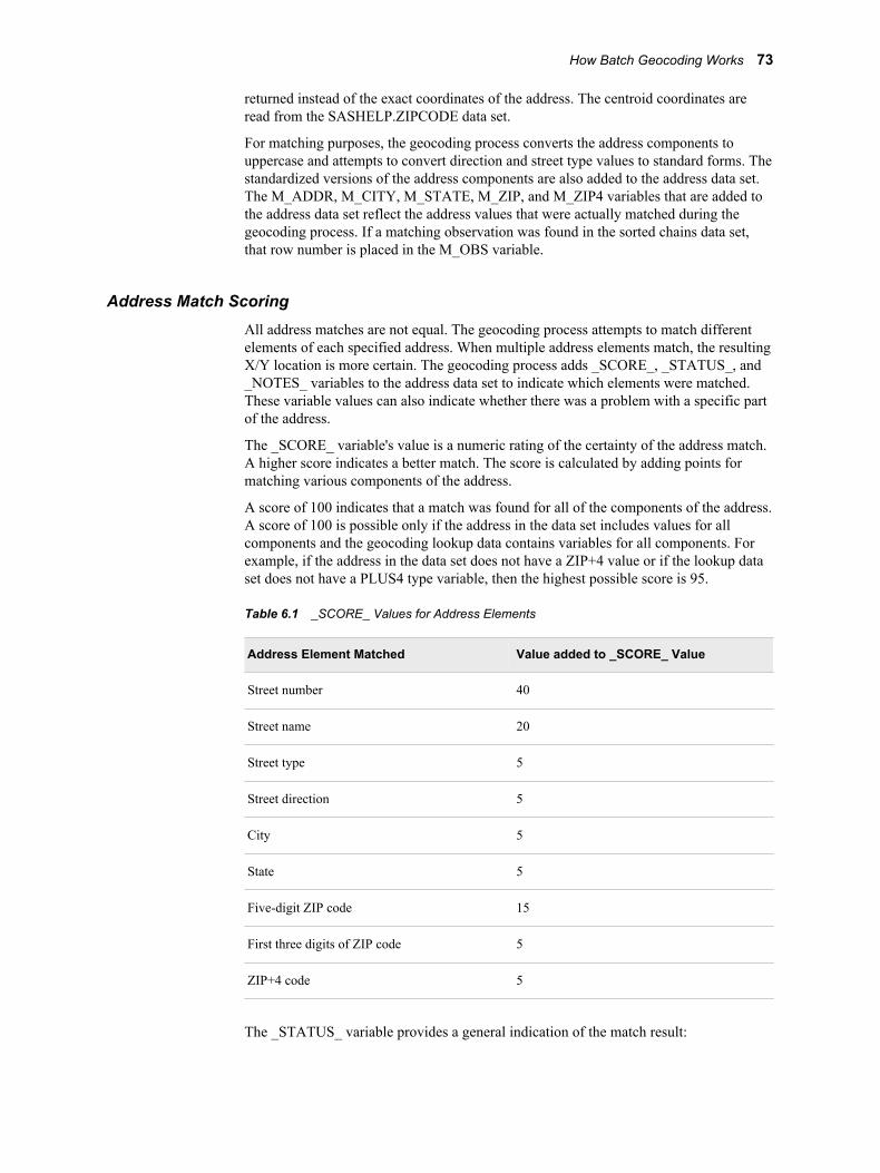
returned instead of the exact coordinates of the address. The centroid coordinates areread from the SASHELP.ZIPCODE data set.
For matching purposes, the geocoding process converts the address components touppercase and attempts to convert direction and street type values to standard forms. Thestandardized versions of the address components are also added to the address data set.The M_ADDR, M_CITY, M_STATE, M_ZIP, and M_ZIP4 variables that are added tothe address data set reflect the address values that were actually matched during thegeocoding process. If a matching observation was found in the sorted chains data set,that row number is placed in the M_OBS variable.
Address Match ScoringAll address matches are not equal. The geocoding process attempts to match differentelements of each specified address. When multiple address elements match, the resultingX/Y location is more certain. The geocoding process adds _SCORE_, _STATUS_, and_NOTES_ variables to the address data set to indicate which elements were matched.These variable values can also indicate whether there was a problem with a specific partof the address.
The _SCORE_ variable's value is a numeric rating of the certainty of the address match.A higher score indicates a better match. The score is calculated by adding points formatching various components of the address.
A score of 100 indicates that a match was found for all of the components of the address.A score of 100 is possible only if the address in the data set includes values for allcomponents and the geocoding lookup data contains variables for all components. Forexample, if the address in the data set does not have a ZIP+4 value or if the lookup dataset does not have a PLUS4 type variable, then the highest possible score is 95.
Table 6.1 _SCORE_ Values for Address Elements
Address Element Matched Value added to _SCORE_ Value
Street number 40
Street name 20
Street type 5
Street direction 5
City 5
State 5
Five-digit ZIP code 15
First three digits of ZIP code 5
ZIP+4 code 5
The _STATUS_ variable provides a general indication of the match result:
How Batch Geocoding Works 73
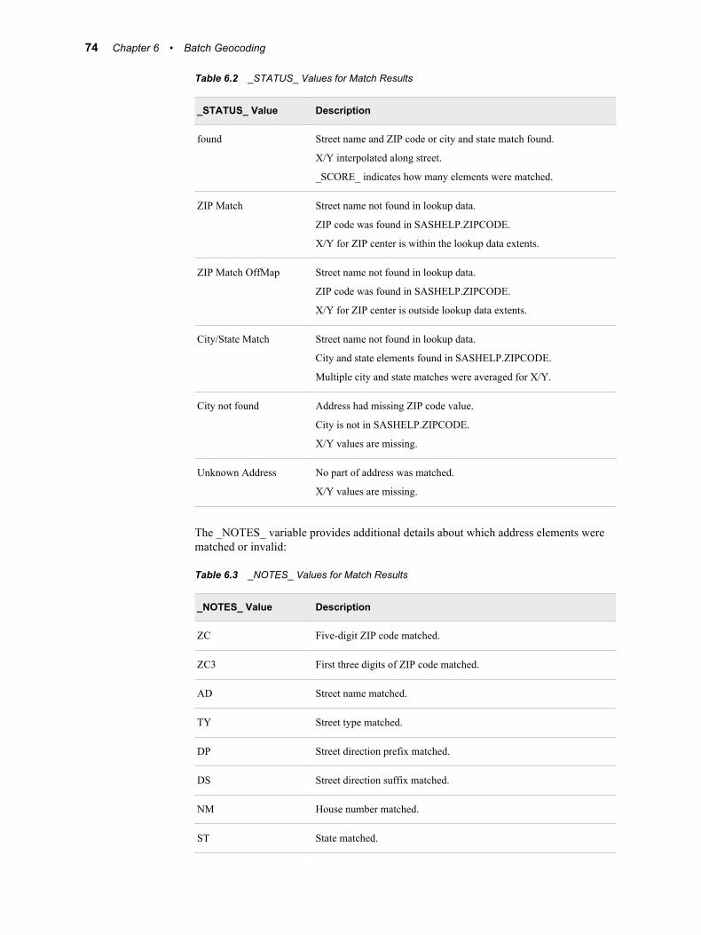
Table 6.2 _STATUS_ Values for Match Results
_STATUS_ Value Description
found Street name and ZIP code or city and state match found.
X/Y interpolated along street.
_SCORE_ indicates how many elements were matched.
ZIP Match Street name not found in lookup data.
ZIP code was found in SASHELP.ZIPCODE.
X/Y for ZIP center is within the lookup data extents.
ZIP Match OffMap Street name not found in lookup data.
ZIP code was found in SASHELP.ZIPCODE.
X/Y for ZIP center is outside lookup data extents.
City/State Match Street name not found in lookup data.
City and state elements found in SASHELP.ZIPCODE.
Multiple city and state matches were averaged for X/Y.
City not found Address had missing ZIP code value.
City is not in SASHELP.ZIPCODE.
X/Y values are missing.
Unknown Address No part of address was matched.
X/Y values are missing.
The _NOTES_ variable provides additional details about which address elements werematched or invalid:
Table 6.3 _NOTES_ Values for Match Results
_NOTES_ Value Description
ZC Five-digit ZIP code matched.
ZC3 First three digits of ZIP code matched.
AD Street name matched.
TY Street type matched.
DP Street direction prefix matched.
DS Street direction suffix matched.
NM House number matched.
ST State matched.
74 Chapter 6 • Batch Geocoding
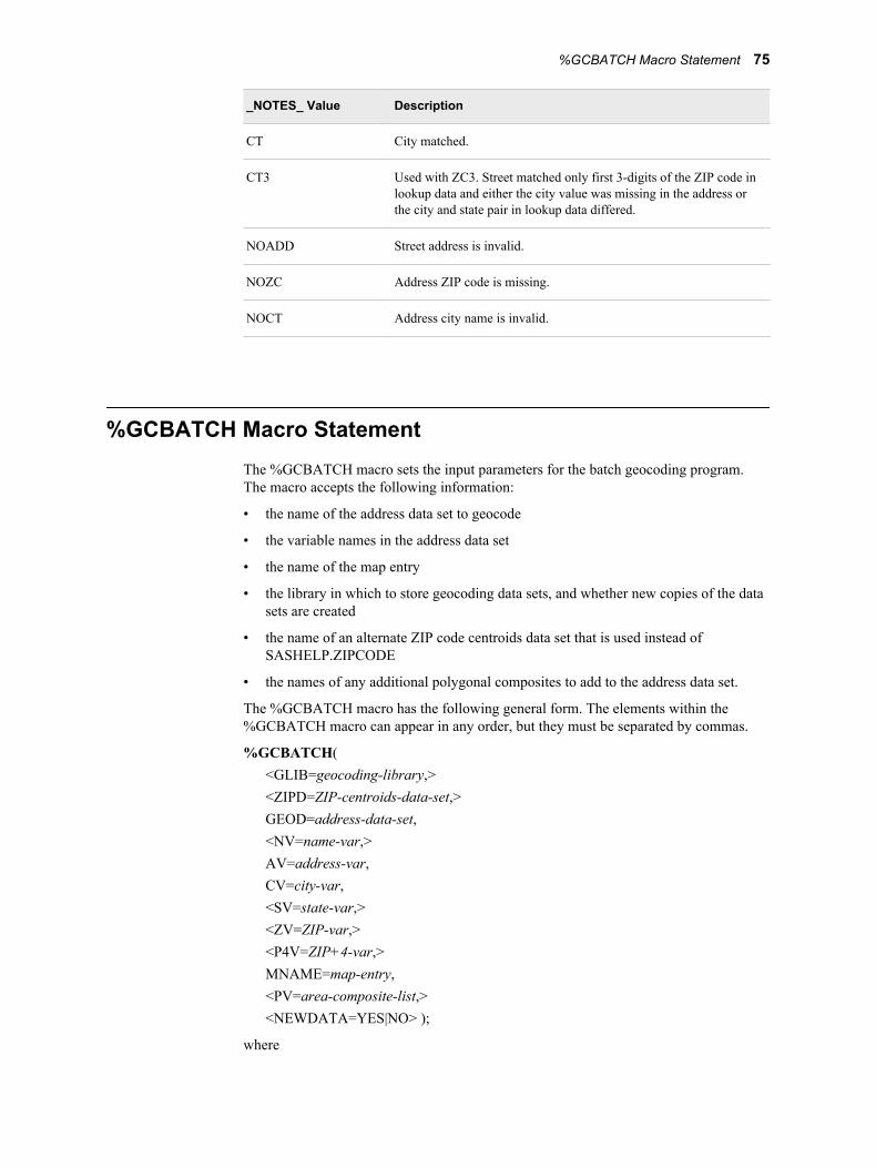
_NOTES_ Value Description
CT City matched.
CT3 Used with ZC3. Street matched only first 3-digits of the ZIP code inlookup data and either the city value was missing in the address orthe city and state pair in lookup data differed.
NOADD Street address is invalid.
NOZC Address ZIP code is missing.
NOCT Address city name is invalid.
%GCBATCH Macro StatementThe %GCBATCH macro sets the input parameters for the batch geocoding program.The macro accepts the following information:
• the name of the address data set to geocode
• the variable names in the address data set
• the name of the map entry
• the library in which to store geocoding data sets, and whether new copies of the datasets are created
• the name of an alternate ZIP code centroids data set that is used instead ofSASHELP.ZIPCODE
• the names of any additional polygonal composites to add to the address data set.
The %GCBATCH macro has the following general form. The elements within the%GCBATCH macro can appear in any order, but they must be separated by commas.
%GCBATCH(<GLIB=geocoding-library,><ZIPD=ZIP-centroids-data-set,>GEOD=address-data-set,<NV=name-var,>AV=address-var,CV=city-var,<SV=state-var,><ZV=ZIP-var,><P4V=ZIP+4-var,>MNAME=map-entry,<PV=area-composite-list,><NEWDATA=YES|NO> );
where
%GCBATCH Macro Statement 75
AV=address-varspecifies the name of the variable that stores the complete street address in theaddress data set that you want to geocode. This includes the house number, streetname, and street type (for example, 3922 Oak Avenue). This parameter is required.
CV=city-varspecifies the name of the variable that stores the city name portion of the address inthe address data set that you want to geocode. This parameter is required.
GEOD=address-data-setspecifies the address data set that you want to geocode. This parameter is required.
GLIB=geocoding-libraryspecifies the libref for the SAS library where all of the sorted and summarizedchains, nodes, and details data sets that are created for the geocoding process arestored. This parameter is optional.
Note: The SAS library that you specify for the GLIB= argument should be on avolume that has a large amount of free space because the geocoding data setsmight be quite large. Also, to take full advantage of the geocoding facility, youshould specify a permanent SAS library. The default for this variable is WORK,but data sets in the WORK library are deleted when the SAS session isterminated, so the geocoding data sets are lost. If geocoding data sets alreadyexist in the specified library at the start of the geocoding process, the geocodingfacility checks their creation dates against the creation date of the chains data set.The geocoding data sets are created again only if the chains data set has a morerecent creation date. The first time you geocode with a particular chains data set,the process takes considerably longer because these geocoding data sets are beingcreated, sorted, and indexed. Subsequent geocoding times, however, are muchfaster as long as the parent chains data set has not been modified.
MNAME=map-entryspecifies the name of the GISMAP entry for the SAS/GIS spatial database (thechains, nodes, and details data sets) that you are using for geocoding. The geocodingprocess uses the projection information in the map entry to ensure that the X and Ycoordinates that are returned for the address will be in the same coordinate system asthe spatial data for the map. The MNAME= argument should use the formlibref.catalog-name.entry-name. This parameter is required.
NEWDATA=YES|NOspecifies whether the geocoding lookup data sets are created again if they alreadyexist. The default is NEWDATA=NO. If you set NEWDATA=NO, the geocodingfacility searches the SAS library that you specified with the GLIB macro variable forgeocode data sets that were created for the spatial entry. The geocoding facilitychecks the creation date of existing geocode data sets against the creation date of thespatial entry. If the creation date of the geocode data sets is more recent than thecreation dates of the spatial entry, the geocoding facility uses the geocode data sets.Otherwise it creates new geocode data sets.
Use NEWDATA=YES to force the geocoding facility to build new versions of thegeocoding data sets. You should specify NEWDATA=YES if the existing geocodingdata sets were created with an earlier version of SAS/GIS software. This parameter isoptional.
NV=name-varspecifies the name of the variable that stores the name portion of the address in theaddress data set that you want to geocode.
This parameter is optional.
76 Chapter 6 • Batch Geocoding
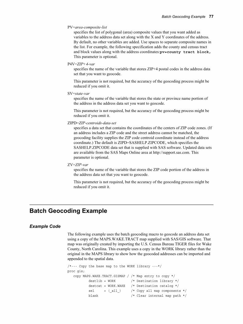
PV=area-composite-listspecifies the list of polygonal (area) composite values that you want added asvariables to the address data set along with the X and Y coordinates of the address.By default, no other variables are added. Use spaces to separate composite names inthe list. For example, the following specification adds the county and census tractand block values along with the address coordinates:pv=county tract block,This parameter is optional.
P4V=ZIP+4-varspecifies the name of the variable that stores ZIP+4 postal codes in the address dataset that you want to geocode.
This parameter is not required, but the accuracy of the geocoding process might bereduced if you omit it.
SV=state-varspecifies the name of the variable that stores the state or province name portion ofthe address in the address data set you want to geocode.
This parameter is not required, but the accuracy of the geocoding process might bereduced if you omit it.
ZIPD=ZIP-centroids-data-setspecifies a data set that contains the coordinates of the centers of ZIP code zones. (Ifan address includes a ZIP code and the street address cannot be matched, thegeocoding facility supplies the ZIP code centroid coordinate instead of the addresscoordinate.) The default is ZIPD=SASHELP.ZIPCODE, which specifies theSASHELP.ZIPCODE data set that is supplied with SAS software. Updated data setsare available from the SAS Maps Online area at http://support.sas.com. Thisparameter is optional.
ZV=ZIP-varspecifies the name of the variable that stores the ZIP code portion of the address inthe address data set that you want to geocode.
This parameter is not required, but the accuracy of the geocoding process might bereduced if you omit it.
Batch Geocoding Example
Example CodeThe following example uses the batch geocoding macro to geocode an address data setusing a copy of the MAPS.WAKE.TRACT map supplied with SAS/GIS software. Thatmap was originally created by importing the U.S. Census Bureau TIGER files for WakeCounty, North Carolina. This example uses a copy in the WORK library rather than theoriginal in the MAPS library to show how the geocoded addresses can be imported andappended to the spatial data.
/*--- Copy the base map to the WORK library ---*/proc gis; copy MAPS.WAKE.TRACT.GISMAP / /* Map entry to copy */ destlib = WORK /* Destination library */ destcat = WORK.WAKE /* Destination catalog */ sel = (_all_) /* Copy all map components */ blank /* Clear internal map path */
Batch Geocoding Example 77
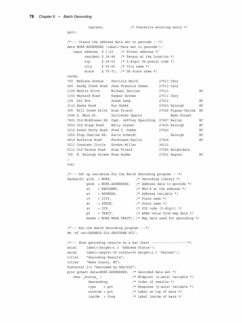
replace; /* Overwrite existing entry */quit;
/*--- Create the address data set to geocode ---*/data WORK.ADDRESSES (label='Data set to geocode'); input address $ 1-23 /* Street address */ resident $ 24-48 /* Person at the location */ zip $ 49-53 /* 5-digit US postal code */ city $ 55-69 /* City name */ state $ 70-71; /* US state name */cards;700 Madison Avenue Patricia Smith 27513 Cary506 Reedy Creek Road Jean Francois Dumas 27513 Cary1106 Medlin Drive Michael Garriss 27511 NC1150 Maynard Road Kaspar Gutman 27511 Cary138 Dry Ave. Susan Lang 27511 NC3112 Banks Road Roy Hobbs 27603 Raleigh NC305 Mill Creek Drive Alan Picard 27526 Fuquay-Varina NC1998 S. Main St. Guillermo Ugarte Wake Forest7825 Old Middlesex Rd Capt. Jeffrey Spaulding 27807 Bailey NC5550 Old Stage Road Emily Joyner 27603 Raleigh NC3212 Avent Ferry Road Fred C. Dobbs 27540 NC1050 King Charles Rd. Karin Schmidt . Raleigh NC6819 Buffaloe Road Ferdinand Paulin 27604 NC3211 Constant Circle Gordon Miller 341216111 Old Faison Road Alan Picard 27545 Knightdale725 N. Raleigh Street Evan Rudde 27501 Angier NC;run;
/*--- Set up variables for the Batch Geocoding program ---*/%gcbatch( glib = WORK, /* Geocoding library */ geod = WORK.ADDRESSES, /* Address data to geocode */ nv = RESIDENT, /* Who's at the address */ av = ADDRESS, /* Address variable */ cv = CITY, /* Place name */ sv = STATE, /* State name */ zv = ZIP, /* ZIP code (5-digit) */ pv = TRACT, /* AREA value from map data */ mname = WORK.WAKE.TRACT); /* Map data used for geocoding */
/*--- Run the Batch Geocoding program ---*/dm 'af cat=SASHELP.GIS.GEOCODEB.SCL';
/*--- Show geocoding results on a bar chart -------------------*/axis1 label=(height=1.3 'Address Status');axis2 label=(angle=-90 rotate=90 height=1.3 'Percent');title1 "Geocoding Results";title2 "Wake County, NC";footnote1 j=l "Geocoded by SAS/GIS";proc gchart data=WORK.ADDRESSES; /* Geocoded data set */ vbar _status_ / /* Midpoint (x-axis) variable */ descending /* Order of results */ type = pct /* Response (y-axis) variable */ outside = pct /* Label on top of bars */ inside = freq /* Label inside of bars */
78 Chapter 6 • Batch Geocoding
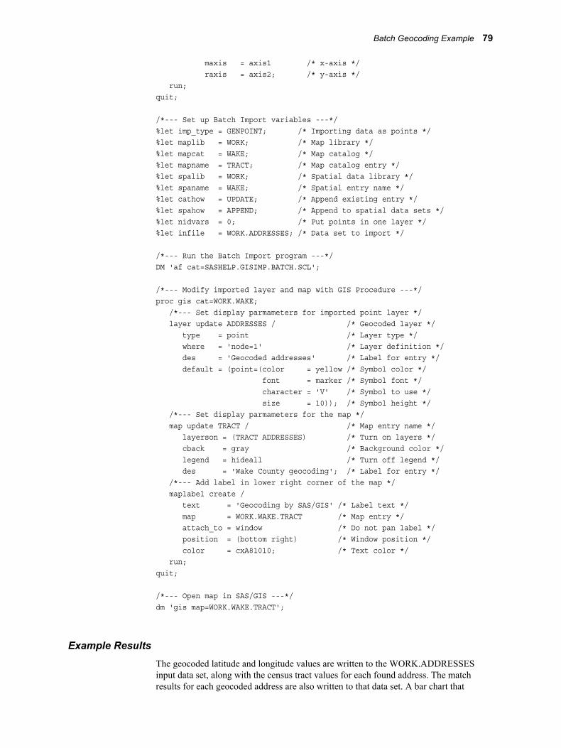
maxis = axis1 /* x-axis */ raxis = axis2; /* y-axis */ run;quit;
/*--- Set up Batch Import variables ---*/%let imp_type = GENPOINT; /* Importing data as points */%let maplib = WORK; /* Map library */%let mapcat = WAKE; /* Map catalog */%let mapname = TRACT; /* Map catalog entry */%let spalib = WORK; /* Spatial data library */%let spaname = WAKE; /* Spatial entry name */%let cathow = UPDATE; /* Append existing entry */%let spahow = APPEND; /* Append to spatial data sets */%let nidvars = 0; /* Put points in one layer */%let infile = WORK.ADDRESSES; /* Data set to import */
/*--- Run the Batch Import program ---*/DM 'af cat=SASHELP.GISIMP.BATCH.SCL';
/*--- Modify imported layer and map with GIS Procedure ---*/proc gis cat=WORK.WAKE; /*--- Set display parmameters for imported point layer */ layer update ADDRESSES / /* Geocoded layer */ type = point /* Layer type */ where = 'node=1' /* Layer definition */ des = 'Geocoded addresses' /* Label for entry */ default = (point=(color = yellow /* Symbol color */ font = marker /* Symbol font */ character = 'V' /* Symbol to use */ size = 10)); /* Symbol height */ /*--- Set display parmameters for the map */ map update TRACT / /* Map entry name */ layerson = (TRACT ADDRESSES) /* Turn on layers */ cback = gray /* Background color */ legend = hideall /* Turn off legend */ des = 'Wake County geocoding'; /* Label for entry */ /*--- Add label in lower right corner of the map */ maplabel create / text = 'Geocoding by SAS/GIS' /* Label text */ map = WORK.WAKE.TRACT /* Map entry */ attach_to = window /* Do not pan label */ position = (bottom right) /* Window position */ color = cxA81010; /* Text color */ run;quit;
/*--- Open map in SAS/GIS ---*/dm 'gis map=WORK.WAKE.TRACT';
Example ResultsThe geocoded latitude and longitude values are written to the WORK.ADDRESSESinput data set, along with the census tract values for each found address. The matchresults for each geocoded address are also written to that data set. A bar chart that
Batch Geocoding Example 79
summarizes the results of the geocoding process is generated using the GCHARTprocedure in SAS/GRAPH software.
When the import is complete, the map opens in SAS/GIS. The found locations are in themap's ADDRESSES point layer.
Note: The WHERE clause for the ADDRESSES point layer is WHERE='NODE=1',which displays points for all of the found addresses. You can modify the WHEREclause to show only those addresses that were matched with a higher degree ofcertainty (for example,.WHERE='_SCORE_>=40').
Note: For a more detailed example of batch geocoding, see the article “CheapGeocoding: SAS/GIS and TIGER Data,” available in the Geocoding section of theDownloads page in the SAS Maps Online area at http://support.sas.com.The article is a reprint of a presentation from SUGI 30 and is also available in theproceedings for that conference.
Hints and Tips for Batch Geocoding• To ensure good quality and accurate geocoding results, you must use accurate data.
If your map's address data is incomplete or out of date, your geocoding will notdeliver the results that you want.
• You can import the geocoded addresses onto a map. However, before you import thepoints, you must make sure that your address data set contains a variable named IDthat has a unique value for each point.
• The input address data set that contains the addresses that you want to geocodeshould contain variables for the street address, city, state, and ZIP code (and anoptional ZIP+4 code) of the addresses to be matched. The address data set can alsocontain a name that is associated with the address, but the name is not used in theaddress matching. In order for the geocoding facility to most accurately parse theaddresses, follow these guidelines:
• Use only street addresses. Post office boxes, rural routes, grid addresses, andaddresses with alphanumeric characters cannot be geocoded. An addresscontaining a post office box or a rural route address in addition to a street addressshould not cause a problem.
• The street number portion of the street address should not contain non-numericcharacters. For example, an address such as 501-B Kent St will be matchedto 501 Kent St., not to the full address containing the non-numeric character.Apartment numbers should be stored in separate variables rather than appendedto the street number.
• Use the following values for directional prefixes and suffixes, with nopunctuation or spaces between letters:
N S E W NE NW SE SW
• Avoid using abbreviations that conflict with street name abbreviations. Forexample, do not use St John St. Use Saint John St instead. Spelling outSaint reduces chances for confusion.
Note: The results from the geocoding are written back to the address data set, so youmust have Write access to it or make a copy that you can write to.
80 Chapter 6 • Batch Geocoding

• You can create your own geocoding lookup data sets for specific areas of the UnitedStates by downloading and importing TIGER data from the U.S. Census Bureau. See“Importing Spatial Data” on page 21 for more information.
You can also download ready-to-use geocoding lookup data sets for the entire UnitedStates from the SAS Maps Online area at http://support.sas.com. Afterdownloading and installing these data sets, you can use them to geocode any U.S.address.
Hints and Tips for Batch Geocoding 81

82 Chapter 6 • Batch Geocoding
Chapter 7
The GIS Procedure
Overview: GIS Procedure . . . . . . . . . . . . . . . . . . . . . . . . . . . . . . . . . . . . . . . . . . . . . . 83
Concepts: GIS Procedure . . . . . . . . . . . . . . . . . . . . . . . . . . . . . . . . . . . . . . . . . . . . . . . 84How GIS Procedure Statements Are Processed . . . . . . . . . . . . . . . . . . . . . . . . . . . . 84Data Set Names in the GIS Procedure . . . . . . . . . . . . . . . . . . . . . . . . . . . . . . . . . . . 85Catalog Entry Names in the GIS Procedure . . . . . . . . . . . . . . . . . . . . . . . . . . . . . . . 85
Syntax: The GIS Procedure . . . . . . . . . . . . . . . . . . . . . . . . . . . . . . . . . . . . . . . . . . . . . 86PROC GIS Statement . . . . . . . . . . . . . . . . . . . . . . . . . . . . . . . . . . . . . . . . . . . . . . . . 86CATALOG Statement . . . . . . . . . . . . . . . . . . . . . . . . . . . . . . . . . . . . . . . . . . . . . . . 87SPATIAL Statement . . . . . . . . . . . . . . . . . . . . . . . . . . . . . . . . . . . . . . . . . . . . . . . . . 88COMPOSITE Statement . . . . . . . . . . . . . . . . . . . . . . . . . . . . . . . . . . . . . . . . . . . . . . 93POLYGONAL INDEX Statement . . . . . . . . . . . . . . . . . . . . . . . . . . . . . . . . . . . . . . 98LATTICE Statement . . . . . . . . . . . . . . . . . . . . . . . . . . . . . . . . . . . . . . . . . . . . . . . . 102COVERAGE Statement . . . . . . . . . . . . . . . . . . . . . . . . . . . . . . . . . . . . . . . . . . . . . 104LAYER Statement . . . . . . . . . . . . . . . . . . . . . . . . . . . . . . . . . . . . . . . . . . . . . . . . . 107LAYERLABEL Statement . . . . . . . . . . . . . . . . . . . . . . . . . . . . . . . . . . . . . . . . . . . 124MAP Statement . . . . . . . . . . . . . . . . . . . . . . . . . . . . . . . . . . . . . . . . . . . . . . . . . . . . 133MAPLABEL Statement . . . . . . . . . . . . . . . . . . . . . . . . . . . . . . . . . . . . . . . . . . . . . 146COPY Statement . . . . . . . . . . . . . . . . . . . . . . . . . . . . . . . . . . . . . . . . . . . . . . . . . . . 153MOVE Statement . . . . . . . . . . . . . . . . . . . . . . . . . . . . . . . . . . . . . . . . . . . . . . . . . . 156SYNC Statement . . . . . . . . . . . . . . . . . . . . . . . . . . . . . . . . . . . . . . . . . . . . . . . . . . . 158
Overview: GIS ProcedureThe GIS procedure creates and maintains the spatial databases that are used by SAS/GISsoftware. A SAS/GIS spatial database consists of the following elements:
• SAS data sets that contain the coordinates and identifying information for the spatialfeatures.
• a spatial entry (a SAS catalog entry of type GISSPA) that identifies which SAS datasets contain spatial information. The spatial entry also stores the following elements:
• composites that define how the variables in the spatial data are used
• names of the polygonal indexes that define the boundaries of area layers for themap
• a lattice hierarchy that defines which features in the spatial data enclose or areenclosed by other features (the relationships among the polygonal variables)
• information about the projection method that is used for the stored spatial data
83
A spatial entry alternatively can contain references to two or more other spatialentries that have been merged into a single spatial database.
• a coverage entry (a SAS catalog entry of type GISCOVER) that selects a subset ofthe spatial data that is available for display in a map.
• one or more layer entries (SAS catalog entries of type GISLAYER) that identifyfeatures that have common characteristics and specify how they are displayed aslayers in the map.
• a map entry (a SAS catalog entry of type GISMAP) that specifies which layers froma particular coverage are included in a map. The map entry also stores the followinginformation:
• the names of attribute data sets that are associated with the map, along withdefinitions of how the attribute data is linked to the spatial data
• the name of a SAS data set that contains labels for map features
• definitions of GIS actions that can be performed when map features are selected
• definitions for map legends
• values for display and projection options
Note: The task of creating new SAS/GIS spatial databases from spatial data in otherformats can also be performed interactively by using the GIS Spatial Data Importingwindow or programmatically by using the SAS/GIS batch import process.
Concepts: GIS Procedure
How GIS Procedure Statements Are ProcessedThe GIS procedure supports RUN-group processing. RUN-group processing enables youto invoke the procedure and then submit additional procedure statements withoutsubmitting the PROC statement again.
In other SAS procedures that do not support RUN-group processing, a RUN statementthat follows a block of submitted statements terminates the procedure. With RUN-groupprocessing, a RUN statement executes the preceding block of statements, but theprocedure remains active. You can continue to submit additional statements for theactive procedure without resubmitting the PROC statement. For example, the followingcode invokes the GIS procedure, assigns a default catalog, and identifies the currentspatial entry:
proc gis catalog=mymaps.region; spatial norwest;
Note: The SPATIAL, CATALOG, LATTICE, COPY, MOVE, and SYNC statementsare immediate statements for the GIS procedure. That is, they are always processedimmediately and do not require a RUN statement (although including a RUNstatement does not do any harm).
After you invoke the GIS procedure, suppose that you also want to define composites.You can submit additional GIS procedure statements to define the composites withoutsubmitting a new PROC statement, as shown in the following example:
84 Chapter 7 • The GIS Procedure
composite create state / class=state var=(left=statel,right=stater);composite create county / class=area var=(left=countyl,right=countyr); composite create lat / class=y var=y; composite create lon / class=x var=x;run;
You can end RUN-group processing and terminate the GIS procedure by submitting aQUIT statement:
quit;
Submitting another PROC step, a DATA step, or an ENDSAS statement also ends RUN-group processing and terminates the GIS procedure.
Note: Certain error conditions might also terminate the GIS procedure. If this occurs, amessage is printed in the SAS log.
Data Set Names in the GIS ProcedureYou can specify a data set by its complete two-level name as in libref.data-set. If youomit the libref value, the data set is assumed to be in the library specified in theCATALOG= option in the PROC GIS statement or in the catalog that was specified bythe most recent CATALOG statement.
Note: If a one-level catalog name was used in the CATALOG= option or CATALOGstatement, or if no default catalog has been named, the default library is WORK, forexample, WORK.data-set.
Catalog Entry Names in the GIS ProcedureYou can specify a GIS catalog entry by its complete three-level name,libref.catalog.entry-name. If you use only the one-level entry-name value, the entry isassumed to be in the catalog that is specified in the CATALOG= option in the PROCGIS statement or in the catalog specified by the most recent CATALOG statement.
Note: If the libref value was omitted from the CATALOG= option or catalog statement,the default library is WORK. If no default catalog has been declared, and a one-levelentry-name value is used, then an error is written to the log because of insufficientinformation to identify the entry.
Concepts: GIS Procedure 85
Syntax: The GIS ProcedurePROC GIS <CATALOG=<libref.>catalog>;
CATALOG <libref.>catalog;SPATIAL <operation> <libref.catalog.>spatial-entry </ options>;COMPOSITE operation composite-name </ options>;POLYGONAL INDEX operation polygonal-index </ options>;LATTICE outer-composite-name-1 ENCLOSES inner-composite-name-1
<…outer-composite-name-n ENCLOSES inner-composite-name-n><_UNIVERSE_ ENCLOSES inner-composite-name>;
COVERAGE operation <libref.catalog.>coverage-entry </ options>;LAYER operation <libref.catalog.>layer-entry </ options>;LAYERLABEL operation <options>;MAP operation <libref.catalog.>map-entry </ options>;MAPLABEL<operation> <option>COPY <libref.catalog.>entry-name<.type> </ options> ;MOVE <libref.catalog.>entry-name<.type> </ options>;SYNC <libref.catalog.>entry-name<.type> </ options>;
PROC GIS StatementInvokes the GIS procedure and specifies the default SAS catalog in which the spatial, coverage, layer, andmap entries are stored.
SyntaxPROC GIS <CATALOG=<libref.>catalog-name>;
Optional ArgumentCATALOG=<libref.>catalog-name
specifies the default SAS catalog in which the GIS spatial, coverage, layer, and mapentries referred to in subsequent statements in the PROC GIS step are stored. If thespecified catalog does not already exist, it is created when a subsequent SPATIAL,COVERAGE, LAYER, or MAP statement is executed.Alias:
CAT=C=
Default: If you omit the libref value in the argument, the default SAS library,WORK, is used.
DetailsThe CATALOG= argument is overridden when you perform one of the following:
• issue a CATALOG statement in conjunction with the PROC GIS statement.Subsequent statements in the GIS procedure will refer to the catalog that was named
86 Chapter 7 • The GIS Procedure
in the most recent CATALOG statement rather than to the one that is specified in theCATALOG= option in the PROC GIS statement.
• specify fully qualified (three-level) entry names in SPATIAL, COVERAGE,LAYER, or MAP statements. This temporarily overrides the default catalog for thecurrent statement only. It does not reset any catalog that is specified with theCATALOG= option. See the descriptions of these statements for more information.
CATALOG StatementIdentifies the default SAS catalog in which GIS spatial, coverage, layer, and map entries are stored whenyou specify one-level catalog entry names in subsequent statements in the PROC step.
Note: The CATALOG statement permanently replaces the CATALOG= option that isspecified in the PROC GIS statement. If you use the CATALOG= option in thePROC GIS statement and then submit a CATALOG statement, subsequentstatements in the GIS procedure refer to the catalog that was named in the mostrecent CATALOG statement.
SyntaxCATALOG <CONTENTS <options>> <libref.>catalog-name;
Required Argument<libref.>catalog-name
specifies the name of the catalog that is used in CREATE, REPLACE, and UPDATEoperations in subsequent statements. If the specified catalog does not already exist, itis created when a subsequent SPATIAL, COVERAGE, LAYER, or MAP statementis executed.Default: If you do not specify a libref, the WORK library is used.
OperationCONTENTS <options>
displays information about the entries in the specified catalog to the SAS Outputwindow. The CONTENTS operation takes the following options:
ET = (entry-type-list)specifies the catalog entry types to display. The entry-type-list value can containany combination of MAP, SPATIAL, COVERAGE, and LAYER.
STATEMENTdisplays PROC GIS statements that create the specified entries.
VERBOSElists all information about the catalog (type of map, layers, actions, andassociated data sets).
DetailsYou can temporarily override the CATALOG statement by specifying fully qualified(three-level) entry names in the SPATIAL, COVERAGE, LAYER, and MAPstatements. This does not reset the current default catalog.
CATALOG Statement 87
SPATIAL StatementSelects the spatial entry on which subsequent statements operate, displays information about the contentsof a spatial entry, creates a new spatial entry, replaces an existing spatial entry, modifies thecharacteristics of an existing spatial entry, or deletes a spatial entry.
SyntaxSPATIAL <operation> <libref.catalog.>spatial-entry </ options>;
Summary of Optional Arguments
CARTESIAN | LATLONspecifies the coordinate system that is used in the stored spatial data.
CHAINS=data-setnames the SAS data set that contains chain definitions for the spatialdatabase.
DEGREES | RADIANS | SECONDSspecifies the coordinate units for the stored spatial data when the coordinatesystem is geographic.
DESCRIPTION='string'specifies a descriptive phrase that is stored in the description field of thespatial entry.
DETAILS=data-setnames the SAS data set that contains detail definitions for the spatialdatabase.
EAST | WESTspecifies the hemisphere in which the spatial data points lie.
KEEPspecifies that polygonal index data sets are not deleted when the spatial entryis deleted.
MERGE=(spatial-entry-list) <EDGEMATCH <LINKONLY> | OVERLAP<ZEROMISS>> <ERROR_ROW=integer>
builds a new spatial entry by referencing two or more existing spatial entries.MULT=multiplier-value
specifies a constant value by which the stored spatial data coordinates aremultiplied.
NODES=data-setnames the SAS data set that contains node definitions for the spatial database.
NORTH | SOUTHindicates the hemisphere in which the spatial data points lie.
Required Argument<libref.catalog.>spatial-entry
specifies the spatial (GISSPA) entry that you want to create, replace, update, delete,or make the current spatial entry.CAUTION: Do not use host commands to move or rename SAS data sets that
are referenced in GISSPA entries. Moving or renaming a data set that is
88 Chapter 7 • The GIS Procedure
referred to in a spatial entry breaks the association between the spatial entry andthe data set. To prevent breaking the association, use the PROC GIS MOVEstatement with the CHECKPARENT option instead of a host command.
OperationsNote: If you omit the operation keyword, the SPATIAL statement makes the specified
spatial entry the current spatial entry for subsequent operations. No SPATIALstatement options can be used in a spatial assignment statement that does not includean operation keyword.
CONTENTSprints information about the specified spatial entry to the Output window, includingthe following:
• a list of the dependent data objects (data sets or other spatial entries) that storethe spatial data
• a list of the SAS data sets (chains, nodes, details, and polygonal indexes) thatstore the spatial data
• a list of the composites for the spatial data
• the lattice hierarchy for the spatial data
• the storage projection characteristics of the spatial data
An error occurs if the specified spatial entry does not exist.Restriction: No additional arguments (other than the spatial entry name) are used
with the CONTENTS operation.Note: The specified spatial entry does not become the current spatial entry for
subsequent operations unless no spatial entry is currently selected.
CREATEgenerates a new spatial entry in which subsequent composites, polygonal indexnames, and lattice hierarchies that are specified in the GIS procedure are stored. Thenew spatial entry becomes the current spatial entry for subsequent operations.
The SPATIAL CREATE statement does not overwrite existing spatial entries. Anerror occurs if a spatial entry with the specified name already exists. Use SPATIALREPLACE to replace an existing entry.Requirement: For the CREATE operation, you must also specify both the
CHAINS= and NODES= arguments or the MERGE= argument.
DELETEdeletes the specified spatial entry. An error occurs if the specified spatial entry doesnot exist.
By default, any polygonal index data sets that are referred to in the spatial entry arealso deleted. The chains, nodes, or details data sets that are referred to in the spatialentry are not deleted. To retain existing polygonal index data sets when the spatialentry is deleted, use the KEEP argument in the SPATIAL DELETE statement.Restriction: KEEP is the only additional argument (other than the spatial entry
name) that can be used with the DELETE operation.Note: For the DELETE operation, you can also specify the special value _ALL_ for
the spatial entry name argument to delete all spatial entries in the current catalog.CAUTION: Use the DELETE operation with care. The GIS procedure does not
prompt you to verify the request before deleting the spatial entry. Be especiallycareful when you use the _ALL_ keyword.
SPATIAL Statement 89
REPLACEoverwrites the specified spatial entry or creates a new entry if an entry with thespecified name does not exist. The specified spatial entry becomes the current spatialentry for subsequent operations. The SPATIAL REPLACE statement has the effectof canceling all previously issued SPATIAL CREATE, COMPOSITE,POLYGONAL INDEX, and LATTICE statements for the specified spatial entry.Requirement: For the REPLACE operation, you must specify both the CHAINS=
and NODES= arguments or the MERGE= argument.
UPDATEmodifies the specified spatial entry by applying new values for specified arguments.The updated spatial entry becomes the current spatial entry for the subsequentoperations.
An error occurs if there is no existing spatial entry with the specified name.
OptionsWhen you specify CREATE, REPLACE, or UPDATE for the operation argument, youcan specify one or more of the following additional optional arguments. When youspecify DELETE for the operation argument, only the KEEP option is allowed. Separatethe list of arguments from the spatial entry name with a slash (/).
CARTESIAN | LATLONspecifies the coordinate system that is used in the stored spatial data.
CARTESIANdata is in an arbitrary rectangular (plane) coordinate system.
LATLONdata is in a geographic (spherical) coordinate system.
Default: LATLONInteraction: The CARTESIAN and LATLON arguments are ignored when the
MERGE= argument is used.
CHAINS=data-setnames the SAS data set that contains chain definitions for the spatial database. Achain is one or more line segments that connect one node (or point on the map) toanother. For example, a series of chains can represent a railroad or a river.Note: The CHAINS= argument is required when you use the CREATE or
REPLACE keyword and do not specify the MERGE= argument.
DEGREES | RADIANS | SECONDSspecifies the coordinate units for the stored spatial data when the coordinate systemis geographic (LATLON).Default: RADIANSInteraction: This argument is ignored when the CARTESIAN or MERGE=
arguments are used.
DESCRIPTION='string'specifies a descriptive phrase, up to 256 characters long, that is stored in thedescription field of the spatial entry.Default: The default description is blank.
DETAILS=data-setnames the SAS data set that contains detail definitions for the spatial database. Theendpoints of a chain are nodes. Details are the intermediate points along a chainbetween the nodes that delineate angle breaks in chains. They provide a finer
90 Chapter 7 • The GIS Procedure
granularity for the chain's line segments. A data set that contains detail definitionsmight describe the curvy outline of a coastal road.
EAST | WESTspecifies the hemisphere in which the spatial data points lie. EAST refers to pointseast of the Prime Meridian (0 degrees longitude) at Greenwich, England, whileWEST refers to points west of the Prime Meridian.
If your data is in the Western Hemisphere, longitude values (the X coordinates) arenegative, that is -35° 45' 08”. If your data is in the Western Hemisphere but haspositive longitudes, your map is displayed flipped or with the east and westdirections reversed. See “Preparing Spatial Data” on page 11 for an example of thisbehavior. Applying the WEST argument to the spatial data causes the longitudes tobe negated when the data is read in, and the map is displayed correctly.Default: EASTInteraction: This argument is ignored when the CARTESIAN or MERGE=
arguments are used.
KEEPspecifies that polygonal index data sets are not deleted when the spatial entry isdeleted.Restriction: This option is valid only with the DELETE operation.
MERGE=(spatial-entry-list) <EDGEMATCH <LINKONLY> | OVERLAP<ZEROMISS>> <ERROR_ROW=integer>
builds a new spatial entry by referencing two or more existing spatial entries. Thedependent data sets for the spatial entries are not actually combined when you usethe MERGE argument; the new spatial entry includes them by reference. An erroroccurs if any of the specified spatial entries do not exist.
You can specify any of the following additional arguments in conjunction with theMERGE= argument:
EDGEMATCH <LINKONLY>matches common boundaries between the merged spatial entries. Missing valuesalong common boundary chains are filled in where possible by using values fromthe adjoining spatial data sets. The affected chains data sets are rewritten unlessthe LINKONLY option is specified, and you cannot reverse the operation.
ZEROMISSINGtreats any left/right attribute value of zero as a missing value. Otherwise zero isconsidered to be a valid value when performing an EDGEMATCH merge.
ERROR_ROW=integerprints an enhanced error message for the specified spatial data row during anEDGEMATCH merge operation. This option can be useful for determining whatcaused a specific row to fail to merge. The basic log warning will print the rownumber for unmatched chains in all of the merged data sets. Any of these chainnumbers can be used as the ERRORROW= target.
OVERLAPmerges spatial entries without attempting to match boundaries. The chains datasets for the merged entries are not rewritten.
Default: OVERLAP
MULT=multiplier-valuespecifies a constant value by which the stored spatial data coordinates are multiplied.Default: 1Interaction: This argument is ignored when the MERGE= argument is used.
SPATIAL Statement 91
NODES=data-setnames the SAS data set that contains node definitions for the spatial database. Nodesare the endpoints of map chains. A node can also be a single map feature representedby a point. A single node can be the endpoint for multiple chains, as at a streetintersection.Note: The NODES= argument is required when you use the CREATE or REPLACE
keyword and do not specify the MERGE= argument.
NORTH | SOUTHindicates the hemisphere in which the spatial data points lie. If your data is in thesouthern hemisphere (below the equator), latitude values (the Y coordinates) arenegative, for example, -45° 12' 33”. If your data is in the southern hemisphere, butthe latitude values are positive, your map is displayed inverted with the north andsouth directions reversed. Applying the SOUTH argument to the spatial data causesthe latitude values to be negated when the data is read in. The map is displayed withthe correct side up.Default: NORTHInteraction: This argument is ignored when the CARTESIAN or MERGE=
arguments are used.
DetailsA spatial entry is a SAS catalog entry of type GISSPA that defines the components of aSAS/GIS spatial database. The definition specifies which SAS data sets contain spatialinformation, how the data sets are related, and what roles the variables play.
Any composites, polygonal indexes, and lattice hierarchies that are created or updatedduring an invocation of the GIS procedure are stored in the current spatial entry. Anysubsequent COVERAGE statements that are issued within the PROC GIS step subset thedata in the current spatial entry.
No additional arguments (other than the spatial entry name) are used when the operationkeyword is omitted. An error occurs if there is no existing spatial entry that has thespecified name.
Note: When creating or replacing spatial entries, you can either define entirely newspatial entries or merge two or more existing spatial entries.
Examples
Example 1: Define the Current Spatial EntryThe following code fragment makes MAPS.NC.NC.GISSPA the current spatial entrythat is used for subsequent operations:
proc gis cat=maps.nc; spatial nc;
Example 2: Update an Existing Spatial EntryThe following code fragment replaces the existing details data set with MAPS.USAD forthe existing MAPS.USA.USA.GISSPA spatial entry:
spatial update maps.usa.usa / details=maps.usad;
Example 3: Merge Three Existing Spatial DatabasesThe following code fragment creates a new spatial entry that is namedTRIANGLE.GISSPA in the current catalog by merging three existing spatial entries,
92 Chapter 7 • The GIS Procedure
ORANGE, DURHAM, and WAKE. In this example, each of the spatial entries to bemerged is stored in a different library. See “Working with Spatial Data” on page 53 formore information about merging.
spatial create triangle / merge=(gmap1.orange.orange, gmap2.durham.durham, gmap3.wake.wake);
COMPOSITE StatementDefines, modifies, or deletes associations between variables in the chains and nodes data sets.
SyntaxCOMPOSITE operation composite-name </ options>;
Summary of Optional Arguments
BILATERALindicates that the composite is a left/right type for spatial data variables thatapply to the left and right sides of chains.
CLASS=class-typedefines the role of the composite in the spatial database.
VAR=association-declarationdefines a variable or an association between related variables in the currentspatial chains or nodes data set.
Required Argumentcomposite-name
specifies the composite that you want to create, replace, delete, or update. Thecomposite-name value must conform to the following rules for SAS names:
• The name can be no more than 32 characters long.
• The first character must be a letter or underscore (_). Subsequent characters canbe letters, numeric digits, or underscores. Blanks are not permitted.
• Mixed-case names are honored for presentation purposes. However, because anycomparison of names is not case-sensitive, you cannot have two names that differonly in case (for example, State and STATE are read as the same name).
OperationsYou must specify one of the following values for the operation keyword:
CREATEdefines associations between variables in the chains and nodes data sets and storesthese composites in the current spatial entry. The COMPOSITE CREATE statementdoes not overwrite existing composites. A warning is issued and processing of thecurrent RUN group is halted if a composite with the specified name already exists.Use COMPOSITE REPLACE to overwrite an existing composite.Note: Not all spatial database variables are composites of multiple SAS data set
variables. Some composites represent a single SAS data set variable.
COMPOSITE Statement 93
DELETEdeletes the specified composite from the current spatial entry. For the DELETEoperation, you can also specify the following alternative forms for the composite-name argument:
• a list of composite names, separated by spaces, to delete more than onecomposite in a single DELETE operation
• the special value _ALL_ to delete all the composites in the current spatial entry
A warning is issued and processing of the current RUN group is halted if thespecified composite does not exist.Restriction: No additional arguments (other than the composite name) are used with
the DELETE operation.Note: The DELETE operation of the COMPOSITE statement removes a composite
from the spatial entry but does not delete the SAS variables from their respectiveSAS data sets.
CAUTION: Use DELETE with care. The GIS procedure does not prompt you toverify the request before deleting an existing composite. Be especially carefulwhen you use _ALL_.
REPLACEoverwrites the previous definition of a composite in the current spatial entry, orcreates a new composite if the specified composite-name value did not previouslyexist.
UPDATEapplies new values for the specified arguments to an existing composite. A warningis issued and processing of the current RUN group is halted if there is no existingcomposite with the specified name.
OptionsWhen you specify CREATE, REPLACE, or UPDATE for the operation argument in aCOMPOSITE statement, you can specify one or more of the following additionaloptional arguments. Separate the list of options from the composite-name value with aslash (/).
BILATERALindicates that the composite is a left/right type for spatial data variables that apply tothe left and right sides of chains. BILATERAL composites are used to definepolygonal layers in a LAYER statement by denoting chains that have different leftand right values. This argument provides an implicit VAR= argument, where theLEFT= and RIGHT= variable names are constructed by appending L and R to thespecified composite name. For example, the following two statements are equivalent:
composite create state / class=area bilateral;
composite create state / class=area var=(left=statel,right=stater);
CLASS=class-typedefines the role of the composite in the spatial database. The CLASS= option linksspecific functionality to particular composites
The class-type value for the CLASS= option can be one of the following:
ADDRESSindicates that the composite defines addresses in the chains data set that is usedfor geocoding.
94 Chapter 7 • The GIS Procedure
Data set address values are the numeric portion of a street address, for example,the 100 in the street address, 100 North Main Street. A chain has fourvalues to define the address range for each side:
FROMLEFTbeginning address on the left side.
TOLEFTending address on the left side.
FROMRIGHTbeginning address on the right side.
TORIGHTending address on the right side.
When you use specify ADDRESS for the class-type value, you must use thefollowing form of the VAR= argument:
VAR=(<FROMLEFT=>variable, <FROMRIGHT=>variable,<TOLEFT=>variable, <TORIGHT=>variable)
AREAindicates that the composite defines polygonal areas.
For polygonal areas that represent political subdivisions, you can specify thefollowing alternative class-type values to indicate which features the areasrepresent:
COUNTRYindicates that the composite defines countries in the chains data.
COUNTYindicates that the composite defines counties in the chains data.
STATEindicates that the composite defines states in the chains data. Composites ofthis class are used in geocoding.
When you use AREA (or COUNTRY, STATE, or COUNTY) for the class-typevalue, you must specify the bilateral form of the VAR= argument to specify thevariables that identify the features on the left and right sides of each chain in thearea:
VAR=(<LEFT=>variable, <RIGHT=>variable)
CITY | PLACEindicates that the composite defines features that are related to geographiclocation, such as cities. Composites of this class are used in geocoding.
By default, CITY is not considered an AREA-type composite. If your spatial datacontain closed city boundaries, you must explicitly define the composite as anAREA class as well:
composite create towns / var=(cityl cityr) class=(city area);
CLASSIFICATIONindicates that the composite defines a general descriptive value that can be usedto classify features in the map.Note: In order to create new point layers when you add points to the map
interactively in the GIS Map window, you must define at least oneCLASSIFICATION-type composite in the spatial entry.
COMPOSITE Statement 95
DIRECTION_PREFIXindicates that the composite defines the directional prefix component of anaggregate feature name, such as the North in North Main Ave. Compositesof this class are used in geocoding.
DIRECTION_SUFFIXindicates that the composite defines the direction suffix component of anaggregate feature name, such as the South in 2nd St South. Composites ofthis class are used in geocoding.
NAMEindicates that the composite defines the names of features in the chains data, suchas Central Park, or the name component of an aggregate feature name, suchas the Main in E Main St. Composites of this class are used in geocoding.
PLUS4indicates that the composite defines extended postal delivery codes (U.S. ZIP+4)in the chains data. Composites of this class are used in address matching.
By default, PLUS4 is not considered an AREA-type composite. If your chainsdata contain closed ZIP+4 boundaries, you must explicitly define the compositeas an AREA class as well:
composite create zip4 / var=(zip4l zip4r) class=(area plus4);
TYPEindicates that the composite defines the feature type component of an aggregatefeature name, such as the Ave in N Harrison Ave. Composites of this classare used in geocoding.
Xindicates that the composite defines the X coordinates for the nodes in the nodesdata set.
Yindicates that the composite defines the Y coordinates for the nodes in the nodesdata set.
ZIPCODEindicates that the composite defines postal delivery codes in the chains data.Composites of this class are used in geocoding.
By default, ZIPCODE is not considered an AREA-type composite. If your chainsdata set contains closed ZIP code area boundaries, you must explicitly define thecomposite as an AREA class as well:
composite create zip / var=(zipl zipr) class=(zipcode area);
Default: CLASSIFICATION
VAR=association-declarationdefines a variable or an association between related variables in the current spatialchains or nodes data set. Variables for all composites are assumed to be in the chainsdata set except for CLASS=X and CLASS=Y variables, which must be in the nodesdata set.
The VAR= argument is required when you use the CREATE or REPLACEoperations, except in the following circumstances:
• If you omit the VAR= argument and specify CLASS=CLASSIFICATION (oromit the CLASS= argument), the composite-name value that you specify is alsoused as the variable name. For example, the following statements are equivalent:
96 Chapter 7 • The GIS Procedure
composite create cfcc;
composite create cfcc / var=cfcc class=classification;
• If you omit the VAR= argument and specify one of the bilateral class-type valuessuch as AREA or STATE, the suffixes L and R are added to the composite-namevalue to form the variable name pair for the association. For example, thefollowing statements are equivalent:
composite create state / class=state;
composite create state / class=state var=(statel stater);
For other class-type values, the VAR= argument is required when you use theCREATE or REPLACE keywords.
The association-declaration argument for the VAR= option can be one of thefollowing, depending on the class-type values that are specified in the CLASS=option:
variabledeclares a composite consisting of a single SAS variable. Use this form forsingle-variable association classes such as CLASSIFICATION,DIRECTION_PREFIX, DIRECTION_SUFFIX, NAME, TYPE, X, and Y.
(<LEFT=>variable-1, <RIGHT=>variable-2)declares a composite consisting of two variables that represent the left and rightsides of a feature. Association declarations of this form can be used to define theboundaries between elements in the spatial data. Use this form for bilateralassociation classes such as AREA, CITY, COUNTRY, COUNTY, PLACE,STATE, ZIPCODE, and PLUS4.
(<FROMLEFT=>variable-1, <FROMRIGHT=>variable-2, <TOLEFT=>variable-3,<TORIGHT=>variable-4)
declares a composite that consists of four variables that separately represent thebeginning and end of the left and right sides of a feature. Associationdeclarations of this form can be used to define the locations of specific addressesin the spatial data. Use this form for the ADDRESS class.
Note: Variable is the name of a SAS data set variable in the chains data set. An erroroccurs if any of the specified variables do not exist in the chains data set.
DetailsOnce defined, composites can be referenced by other GIS procedure statements. Forexample, if a spatial database contains the variables COUNTYL and COUNTYR thatidentify the chains' left and right values for a county ID variable, you could use theCOMPOSITE statement to create a composite called COUNTY by associating the twospatial database variables. The COUNTY composite could then be used to define thecounty boundaries for the map.
Composites are stored in the currently specified spatial (GISSPA) entry. An error occursif you submit a COMPOSITE statement when no spatial entry is currently selected.
Note: Use the SPATIAL CONTENTS statement to view the composites for a spatialentry. Composite variable values are also displayed in the Spatial Informationwindow when you select a map feature in the GIS Map window.
COMPOSITE Statement 97
Examples
Example 1: Define a Single-Variable CompositeThe following code fragment associates the class Y with the variable named LAT in thenodes data set to indicate that the variable contains north-south coordinate information:
composite create latitude / var=LAT class=y;run;
Example 2: Define a Composite for a Bilateral FeatureBoth of the following code fragments associates a pair of variables in the chains data setthat contain values for the left and right sides of area boundaries:
composite create state / var=(left=statel,right=stater) class=area;run;
composite create state/ bilateral class=area;run;
Example 3: Define a Composite for an Address FeatureThe following code fragment associates two pairs of variables in the chains data set thatcontain values for the corners of address boundaries:
composite create custadd / var=(fromleft=FRADDL,fromright=FRADDR, toleft=TOADDL,toright=TOADDR) class=address;run;
POLYGONAL INDEX StatementCreates, replaces, modifies, or deletes polygonal index data sets by using a libref and polygonal indexreferences from a spatial entry.
SyntaxPOLYGONAL INDEX operation polygonal-index </ options>;
Summary of Optional Arguments
AREAcalculates the enclosed areas and perimeter lengths for the lowest-level areacomposite that is specified on the COMPOSITE= argument.
CENTROID<=GEOMETRIC | VISUAL>specifies the type of centroid data that is returned.
COMPOSITE=(composite-name-1<, …, composite-name-n>)specifies the composite or list of composites that define the boundaries of theenclosed polygonal areas that are used to create the index.
ERRORS<=number>
98 Chapter 7 • The GIS Procedure
specifies whether messages about any topological errors that are detectedwhile the index is being constructed are written to the SAS log.
FORCEindicates that an existing polygonal index data set that is specified in theOUT= argument can be overwritten.
KEEPspecifies that polygonal index data sets are to be retained when the indexdefinition is removed from the spatial entry.
OUT=data-set-namenames the index data set that you want to create, replace, or update.
Required Argumentpolygonal-index
specifies the polygonal index that you want to create, delete, replace, or update. Thepolygonal-index value must conform to the following rules for SAS names:
• The name can be no more than 32 characters long.
• The first character must be a letter or underscore (_). Subsequent characters canbe letters, numeric digits, or underscores. Blanks are not permitted.
• Mixed-case names are honored for presentation purposes. However, because anycomparison of names is not case-sensitive, you cannot have two names that differonly in case (for example, State and STATE are read as the same name).
OperationsYou must specify one of the following values for the operation keyword:
CREATEcreates a polygonal index data set and stores the polygonal index definition in thecurrent spatial entry. The POLYGONAL INDEX CREATE statement does notoverwrite existing index definitions or data sets. A warning is issued and processingof the current RUN group is halted if either a polygonal index definition or a SASdata set with the specified names already exist. Use POLYGONAL INDEXREPLACE to replace an existing index definition or data set.Requirement: For the CREATE operation, you must specify both the
COMPOSITE= and OUT= arguments.
DELETEremoves the specified polygonal index definition from the spatial entry. By default,the POLYGONAL INDEX DELETE statement also deletes the associated index dataset. You can use the KEEP option to prevent the index data set from being deleted.
A warning is issued and processing of the current RUN group is halted if thespecified polygonal index does not exist.
For DELETE, you can also specify the special value _ALL_ for the polygonal-indexargument to delete all the polygonal index definitions in the current spatial entry.Restriction: KEEP is the only additional argument (other than the polygonal index
name) that can be used with the DELETE operation.CAUTION: Use DELETE with care. The GIS procedure does not prompt you to
verify the request before deleting an existing polygonal index. Be especiallycareful when you use the _ALL_.
REPLACEoverwrites the polygonal index definition in the current spatial entry or creates a newpolygonal index definition if the specified index does not exist.
POLYGONAL INDEX Statement 99
Requirement: For the REPLACE operation, you must specify both theCOMPOSITE= and OUT= arguments.
Note: If the data set that is specified in the OUT= argument already exists andbelongs to a different spatial entry, you must specify the FORCE argument tocause it to be overwritten.
UPDATEmodifies only the specified characteristics for an existing polygonal index. Awarning is issued and processing of the current RUN group is halted if there is noexisting polygonal index with the specified name.Note: If the data set that is specified in the OUT= argument already exists and
belongs to a different spatial entry, you must specify the FORCE argument tocause it to be overwritten.
OptionsWhen you specify CREATE, REPLACE, or UPDATE for the operation argument in thePOLYGONAL INDEX statement, you can specify the one or more of the followingadditional optional arguments. When you specify DELETE for the operation argument,only the KEEP option is allowed. Separate the list of arguments from the polygonalindex name with a slash (/).
AREAcalculates the enclosed areas and perimeter lengths for the lowest-level areacomposite that is specified on the COMPOSITE= argument. The calculated area isadded to the polygonal index data set in a variable named AREA. A label for theAREA variable contains the storage area units. The calculated perimeter is added tothe polygonal index data set in a variable named PERIMETER. A label for thePERIMETER variable contains the units.
CENTROID<=GEOMETRIC | VISUAL>specifies the type of centroid data that is returned.
GEOMETRICreturns the actual calculated centroids, which might not fall within the boundariesof their corresponding polygons. The coordinates are added to the polygonalindex data set in variables that are named CTRX and CTRY. Labels for theCTRX and CTRY variables contain the storage projection units and indicate thatthis is a GEOMETRIC centroid. Specifying the CENTROID argument by itselfreturns the same results as specifying CENTROID=GEOMETRIC.
VISUALreturns adjusted centroids that are moved to be within the boundaries of theircorresponding polygons. The coordinates are added to the polygonal index dataset in variables that are named CTRX and CTRY. Labels on the CTRX andCTRY variables contain the storage projection units and indicate that this is aVISUAL centroid.
COMPOSITE=(composite-name-1<, …, composite-name-n>)specifies the composite or list of composites that define the boundaries of theenclosed polygonal areas that are used to create the index. If the composite-name listconsists of a single composite, you can omit the parentheses. An error occurs if anyof the specified composites are not defined in the current spatial entry or if any donot have the CLASS attribute of AREA.Note: The COMPOSITE= argument is required when you use the CREATE or
REPLACE operation.
100 Chapter 7 • The GIS Procedure
ERRORS<=number>specifies whether messages about any topological errors that are detected while theindex is being constructed are written to the SAS log. A polygon boundary consistsof a single chain with the same starting and ending node, or multiple chains that forma closed boundary. The starting node for each boundary chain must be the endingnode of the previous chain. The ending node of the last chain must be the beginningnode of the first boundary chain. A topology error occurs when the polygon is notclosed. You can specify the ERRORS argument with no added parameter to print alltopological error messages, or you can add the =number parameter to specify themaximum number of topological error messages that will be written to the log.
FORCEindicates that an existing polygonal index data set that is specified in the OUT=argument can be overwritten, even if it belongs to a different spatial entry. If youomit this option, the data set is not replaced and a warning is issued.
KEEPspecifies that polygonal index data sets are to be retained when the index definitionis removed from the spatial entry.Restriction: This option is valid only with the DELETE operation.
OUT=data-set-namenames the index data set that you want to create, replace, or update.Note: The OUT= argument is required when you use the CREATE or REPLACE
operation.CAUTION: Do not use host commands to move or rename polygonal index data
sets. Because the polygonal index data set names are stored in GISSPA entries,moving or renaming a polygonal index data set breaks the association betweenthe GISSPA entry and the data set. To prevent breaking the association, use thePROC GIS MOVE statement with the CHECKPARENT option instead of a hostcommand.
DetailsPolygonal indexes delineate enclosed areas in the spatial data by noting the chains thatform polygons. This statement is also used to compute the enclosed areas, the centroidcoordinates, and the perimeter lengths of the individual polygons.
The spatial database must include a polygonal index data set for each feature type thatyou intend to represent as an area layer in the map. For example, to represent states andcounties as enclosed areas, you must have separate polygonal indexes for each.
The POLYGONAL INDEX statement uses composite values from the current spatialentry to determine area boundaries. The composites that are used for polygonal indexesmust have the CLASS attribute AREA (or one of the political subdivision area classessuch as COUNTRY, STATE, or COUNTY that imply AREA by default).
Polygonal index definitions are stored in the currently specified spatial entry. An erroroccurs if you submit a POLYGONAL INDEX statement when no spatial entry iscurrently selected.
Note: You can use the SPATIAL CONTENTS statement to view the polygonal indexdefinitions for a spatial entry.
POLYGONAL INDEX Statement 101
ExampleThe following code fragment builds a polygonal index data set that is namedGMAPS.STATEX. The data set identifies the boundaries of the polygons for the areafeature that is identified by the STATE composite in the current spatial entry:
polygonal index create state / composite=state out=gmaps.statex;run;
LATTICE StatementDefines the relationships between areas in a spatial database.
SyntaxLATTICE operation outer-composite-name-1 ENCLOSES inner-composite-name-1<…outer-composite-name-n ENCLOSES inner-composite-name-n><_UNIVERSE_ ENCLOSES inner-composite-name>;
OperationsYou must specify one of the following values for the operation keyword:
CONTENTSprints information about the lattice hierarchy in the current spatial entry to the Outputwindow.Restriction: No additional arguments are used with the CONTENTS operation.
CREATEcreates a new lattice hierarchy in the current spatial entry. An error occurs if thespatial entry already contains a lattice. Use the REPLACE operation to replace anexisting lattice.
DELETEremoves the lattice hierarchy from the current spatial entry.Restriction: No additional arguments are used with the DELETE operation.
REPLACEoverwrites the lattice hierarchy in the current spatial entry or creates a new latticehierarchy if one does not exist.
Lattice Definition Argumentsouter-composite-name ENCLOSES inner-composite-name
outer-composite-nameis the name of an area composite that geographically contains other enclosed areacomposites.
inner-composite-nameis the name of an area composite that is geographically within the polygonalareas defined by the outer-composite-name.
Requirement: The composites specified for outer-composite-name and inner-composite-name must have the CLASS attribute AREA (or one of the politicalsubdivision area classes such as COUNTRY, STATE, or COUNTY).
102 Chapter 7 • The GIS Procedure
Note: You can substitute the characters -> for the ENCLOSES keyword.
_UNIVERSE_ ENCLOSES inner-composite-name
inner-composite-nameis the name of a single area composite that is not contained by another compositeand that does not itself enclose any other areas.
Requirement: The composite specified for inner-composite-name must have theCLASS attribute AREA (or one of the political subdivision area classes such asCOUNTRY, STATE, or COUNTY).
Note: You can substitute the characters -> for the ENCLOSES keyword.
DetailsThe LATTICE statement defines which areas enclose other smaller areas (such as statesenclose counties). When a lattice hierarchy is defined, the area composite values for newpoints are assigned automatically as the points are added to the map. The compositevalues are also reevaluated automatically when an existing point is moved to a newlocation. A lattice definition also makes it possible to simultaneously assign attributevalues to all points in a point layer by setting area attributes in the GIS Layer window.Area attributes cannot be assigned to new points, moved points, geocoded points, orimported points unless a lattice has been defined.
The lattice definition is written to the current spatial entry. An error occurs if you submita LATTICE statement when no spatial entry is currently selected.
Note: Because the LATTICE statement uses composites, you must include a RUNstatement following a COMPOSITE statement. This ensures that the composite iscreated before the LATTICE statement executes and attempts to use the composite.
The LATTICE statement checks lattice definitions for circular references. For example,a lattice definition of the following form would cause an error:
LATTICE A ENCLOSES B B ENCLOSES C C ENCLOSES B;
Examples
Example 1: Single HierarchyFor a lattice hierarchy that comprises several composites, the general form of theLATTICE statement is
LATTICE CREATE A ENCLOSES BB ENCLOSES CC ENCLOSES D;
Assume that the spatial database contains states that are subdivided into counties, thatthe counties are further subdivided into tracts, that the tracts are further subdivided intoblocks, and that corresponding composites are defined for each. The following codefragment defines the lattice for the spatial database:
lattice create state encloses county county encloses tract tract encloses block;
LATTICE Statement 103
Example 2: Multiple HierarchiesYou can define more than one lattice hierarchy for a spatial database, for example, whenthe map has overlapping AREA-type composites that are not related. A single LATTICEstatement is used, but the GIS procedure recognizes the break between the twohierarchies, as follows:
lattice create state encloses county /* first lattice */ county encloses tract /* first lattice */ tract encloses block /* first lattice */ mall encloses store; /* second unrelated lattice */
Example 3: Single-Element LatticeIf the map has only one AREA-type composite, it is called a universe-enclosedassociation. Use the _UNIVERSE_ keyword to define a lattice for a universe-enclosedassociation, as follows:
lattice create _universe_ encloses tract;
It is possible to have more than one set of unrelated AREA composites, for example, aspatial entry containing counties and telephone area codes. The lattice hierarchy wouldthen be defined as:
lattice create _universe_ encloses AreaCode _universe_ encloses County;
COVERAGE StatementDisplays information about the contents of a coverage entry, creates a new coverage entry, replaces anexisting coverage entry, modifies the characteristics of a previously created coverage entry, or deletes acoverage entry.
SyntaxCOVERAGE operation <libref.catalog.>coverage-entry </ options>;
Summary of Optional Arguments
DESCRIPTION='string'specifies a descriptive phrase that is stored in the description field of theGISCOVER entry.
SPATIAL=spatial-entryspecifies the GISSPA-type entry to which the coverage definition refers.
WHERE=('where-string-1'<… 'where-string-n'>)specifies a WHERE expression that subsets the chains data set to define ageographic coverage of a spatial database.
Required Argumentcoverage-entry
specifies the coverage entry that you want to create, delete, replace, or update. Thecoverage-entry name must conform to the rules for SAS names:
• The name can be no more than 32 characters long.
104 Chapter 7 • The GIS Procedure
• The first character must be a letter or underscore (_). Subsequent characters canbe letters, numeric digits, or underscores. Blanks are not permitted.
• Mixed-case names are honored for presentation purposes. However, because anycomparison of names is not case-sensitive, you cannot have two names that differonly in case (for example, State and STATE are read as the same name).
OperationsYou must specify one of the following values for the operation keyword:
CONTENTSprints information about the specified coverage entry. prints information about thespecified coverage entry to the Output window, including the WHERE expressionthat defines the spatial database subset and details of the spatial database as providedby the SPATIAL CONTENTS statement.
An error occurs if the specified coverage entry does not exist.Restriction: No additional arguments (other than the coverage entry name) are used
with the CONTENTS operation.
CREATEcreates a new coverage entry. The CREATE operation does not overwrite existingcoverage entries. An error occurs if a coverage entry with the specified name alreadyexists. Use the REPLACE operation to replace an existing entry.
Requirement: For the CREATE operation, you must also specify the WHERE=argument.
DELETEremoves the specified coverage entry. For the DELETE operation, you can alsospecify the special value _ALL_ for the coverage entry name argument to delete allcoverage entries in the current catalog.
An error occurs if the specified coverage entry does not exist.Restriction: No additional arguments (other than the coverage entry name) are used
with the DELETE operation.Note: You must specify new coverages for any map entries that refer to the deleted
coverage entry.CAUTION: Use DELETE with care. The GIS procedure does not prompt you to
verify the request before deleting the coverage entry. Be especially careful whenyou use _ALL_.
REPLACEoverwrites the specified coverage entry or creates a new entry if an entry with thespecified name does not exist.
The REPLACE operation has the effect of canceling the previously issued CREATEoperation for the specified coverage entry.Requirement: For a REPLACE operation, you must also specify the WHERE=
argument.
UPDATEmodifies the specified coverage entry by applying new values for specifiedarguments. An error occurs if there is no existing coverage entry with the specifiedname.
COVERAGE Statement 105

OptionsWhen you specify CREATE, REPLACE, or UPDATE for theoperation argument in aCOVERAGE statement, you can specify one or more of the following additionaloptional arguments. Separate the list of options from the coverage-entry argument with aslash (/).
DESCRIPTION='string'specifies a descriptive phrase, up to 256 characters long, that is stored in thedescription field of the GISCOVER entry.Default: Blank
SPATIAL=spatial-entryspecifies the GISSPA-type entry to which the coverage definition refers. An erroroccurs if there is no existing spatial entry that has the specified name, or if you omitthis argument when no spatial entry is currently selected.Default: Current spatial entry
WHERE=('where-string-1'<… 'where-string-n'>)specifies a WHERE expression that subsets the chains data set to define a geographiccoverage of a spatial database. The where-string value can contain a complete validWHERE expression of 200 characters or fewer.
To specify a WHERE expression greater than 200 characters, you must break theexpression into separate quoted strings. When WHERE= is processed, the strings areconcatenated, with a space between each string, and the entire expression isevaluated.
You can specify multiple WHERE expressions to delineate the coverage. If you areusing multiple strings, each string does not have to contain a complete WHEREexpression, but the concatenated expression must be valid.
You can use any of the variables in the chains data set in the WHERE expression,not just the coordinate variables. When the map is opened, only those chains thatmatch the WHERE clause are read in. You can use only variables in the WHEREexpression, not composites. Specify WHERE='1' to define a coverage that includesthe entire spatial database.Note: The WHERE= argument is required when you use the CREATE or
REPLACE operation.
DetailsA coverage entry is a SAS catalog entry of type GISCOVER that contains informationabout the spatial data that is used to create a map. The entry also contains a subsettingWHERE expression to define the subset of spatial data, or coverage, of the map that youwant to display.
For example, you could create a coverage entry, MYCAP, that contains geographicinformation for your state capital. MYCAP subsets the spatial database that is defined inthe spatial entry MYSTATE, which contains geographic information that is used tocreate a map of your entire state.
Note: Even if you want to display the entire geographic scope of your spatial data andnot a subset, you must still create a coverage entry by using WHERE='1'.
106 Chapter 7 • The GIS Procedure
Examples
Example 1: Define a Universal CoverageThe following code fragment creates a coverage entry that is namedGMAPS.USA.ALL.GISCOVER. The code defines a coverage of the entire spatialdatabase that is defined in GMAPS.USA.USA.GISSPA:
proc gis cat=gmaps.usa; spatial usa; coverage create all / where='1';run;
Example 2: Define a Coverage SubsetAssume that the chains data set for the current spatial entry has the variables STATELand STATER that contain FIPS state codes for the states on the left and right side ofeach chain. The following code fragment creates a coverage entry that is namedSOUTHEAST of type GISCOVER. The code defines a coverage of only the selectedstates from the current spatial entry:
coverage create southeast / where=("statel in (1,12,13,28,37,45,47) | stater in (1,12,13,28,37,45,47)");run;
LAYER StatementDisplays information about the contents of a layer entry, creates a new layer entry, replaces an existinglayer entry, modifies the characteristics of an existing layer entry, or deletes a layer entry.
SyntaxLAYER operation <libref.catalog.>layer-entry </ options<theme-options>>;
Summary of Optional Arguments
COMPOSITE=composite-namespecifies a composite that defines the common characteristic of the featuresin the layer.
DEFAULT=(static-arguments)defines the static appearance of a layer.
DESCRIPTION='string'specifies a descriptive phrase that is stored in the description field of the layerentry
DETAILON=scale-valuespecifies the scale at or below which detail coordinates are displayed,provided that detail points are available.
DETAILS | NODETAILSspecifies whether the detail coordinates are read for this layer.
FORCEenables you to create more than one theme by using the same variable fromthe same attribute data set.
LAYER Statement 107

LABELON=scale-valuespecifies the numeric scale at or below which map labels are displayed.
MAP=<libref.catalog.>map-entryidentifies a GISMAP-type entry that provides theme information for layersthat are created in SAS/GIS in Release 6.11 of SAS.
OFFSCALE=scale-valuespecifies the scale at or below which the layer is hidden.
ONSCALE=scale-valuespecifies the scale at or below which the layer is displayed.
STATIC | THEMATICspecifies whether the current theme in the layer is turned on when the map isopened.
THEME=(operation theme-arguments)enables you to modify or delete existing themes or to create new themes.
TYPE=POINT | LINE | AREAspecifies the type of layer.
UNITS=unit-specificationspecifies the scale units for subsequent ONSCALE=, OFFSCALE=, andDETAILON= argument values.
WHERE=('where-string-1' <… 'where-string-n'>)specifies a WHERE expression that subsets the chains data set to define ageographic layer of a spatial database.
Required Argument<libref.catalog.>layer-entry
specifies the layer entry that you want to create, delete, replace, or update. The layer-name value must conform to the following rules for SAS names:
• The name can be no more than 32 characters long.
• The first character must be a letter or underscore (_). Subsequent characters canbe letters, numeric digits, or underscores. Blanks are not permitted.
• Mixed-case names are honored for presentation purposes. However, because anycomparison of names is not case-sensitive, you cannot have two names that differonly in case (for example, State and STATE are read as the same name).
OperationsYou must specify one of the following values for the operation keyword:
CONTENTSdisplays the characteristics of the specified layer entry in the Output window,including the WHERE expression that defines the layer and lists of the layer'sparameters and graphical attributes.
An error occurs if the specified layer entry does not exist.Restriction: No additional arguments (other than the layer entry name) are used
with the CONTENTS operation.
CREATEcreates a new layer entry to define a particular set of features in the spatial database.The LAYER CREATE statement does not overwrite existing layer entries. An erroroccurs if a layer entry with the specified name already exists. Use LAYERREPLACE to replace an existing entry.
108 Chapter 7 • The GIS Procedure
Requirement: For the CREATE operation, you must also specify either theCOMPOSITE= argument or the WHERE= argument. For area layers, you mustuse the COMPOSITE= argument.
DELETEremoves the specified layer entry. For the DELETE operation, you can also specifythe special value _ALL_ for the layer-entry name to delete all layer entries in thecurrent catalog.
An error occurs if the specified layer entry does not exist.Restriction: No additional arguments (other than the layer entry name) are used
with the DELETE operation.Note: You must specify a new layer list for any map entries that refer to the deleted
layer entry.CAUTION: Use DELETE with care. The GIS procedure does not prompt you to
verify the request before deleting the layer entry. Be especially careful when youuse _ALL_.
REPLACEoverwrites the specified layer entry or creates a new layer entry if an entry with thespecified name does not exist. The LAYER REPLACE statement has the effect ofcanceling the previously issued LAYER CREATE statement for the specified layerentry.Requirement: For the REPLACE operation, you must also specify either the
COMPOSITE= argument or the WHERE= argument. For area layers, you mustuse the COMPOSITE= argument.
UPDATEmodifies the specified layer entry by applying new values for specified arguments.An error occurs if there is no existing layer entry with the specified name.
OptionsWhen you specify CONTENTS, CREATE, REPLACE, or UPDATE for the operationargument in a LAYER statement, you can specify one or more of the followingadditional optional arguments. Separate the list of options from the layer-entry argumentwith a slash (/).
COMPOSITE=composite-namespecifies a composite that defines the common characteristic of the features in thelayer. The COMPOSITE= argument is an alternative to specifying a WHEREexpression by using the WHERE= argument. For example, if you specifyCOMPOSITE=STATE in the LAYER statement and the composite named STATEwas created with the variable associationVAR=(LEFT=STATEL,RIGHT=STATER), then the implied WHERE expressionfor the layer is WHERE STATEL NE STATER.Note: Either the COMPOSITE= argument or the WHERE= argument is required
when you use the CREATE or REPLACE operation. For area layers, you mustuse the COMPOSITE= argument.
DEFAULT=(static-arguments)defines the static appearance of a layer. The following are the options:
AREA=(area-arguments)defines the static appearance of the area fills in an area layer. You can specify thefollowing arguments:
LAYER Statement 109
ANGLE=angle-valuespecifies an angle for hatched and crosshatched lines. The ANGLE= valuemust be greater than or equal to zero and less than 90 (for crosshatch), orgreater than or equal to zero and less than 180 (for hatch).Default: 0 (for HATCH and CROSSHATCH)Ranges: 0 – 90 (HATCH), 0 – 180 (CROSSHATCH)
COLOR=colorspecifies the fill color of the area. The color value must be one of thefollowing:
• a SAS color name
• an RGB color code in the form CXrrggbb
• an HLS color code in the form Hhhhllss
• a gray-scale color code in the form GRAYnn
Default: GRAYSee: For more information about color-naming schemes, see “Specifying
Colors in SAS/GRAPH Programs” in SAS/GRAPH: Reference.
SPACING=line-spacingspecifies the spacing between hatched lines or crosshatched lines. The lowerthe number, the less space between lines.Default: 7Range: 2 – 10
STYLE=EMPTY | FILLED | HATCH | CROSSHATCH.specifies the fill style of the area.Default: FILLED (area contains a solid color)
Restriction: The AREA= option is valid only when TYPE=AREA is specifiedin the layer definition.
CENTERLINE=(centerline-arguments)defines the static appearance of the optional centerline in a line layer. You canspecify the following arguments:
COLOR=colorspecifies the color of the centerline. The color value must be one of thefollowing:
• a SAS color name
• an RGB color code in the form CXrrggbb
• an HLS color code in the form Hhhhllss
• a gray-scale color code in the form GRAYnn
Default: BLACKSee: For more information about color naming schemes, see “Specifying
Colors in SAS/GRAPH Programs” in SAS/GRAPH: Reference.
ON | OFFspecifies whether the optional centerline is displayed.Default: OFF
STYLE=SOLID | DASHED | DOTTEDspecifies the style of the centerline.Default: SOLID
110 Chapter 7 • The GIS Procedure
WIDTH=line-widthspecifies the width of the centerline.Default: 1Range: 1 – 20
Restriction: The CENTERLINE= option is valid only when TYPE=LINE isspecified in the layer definition.
LINE=(line-arguments)defines the static appearance of the lines in a line layer. You can specify thefollowing arguments:
COLOR=colorspecifies the color of the line. The color value must be one of the following:
• a SAS color name
• an RGB color code in the form CXrrggbb
• an HLS color code in the form Hhhhllss
• a gray-scale color code in the form GRAYnn
Default: BLACKSee: For more information about color-naming schemes, see “Specifying
Colors in SAS/GRAPH Programs” in SAS/GRAPH: Reference.
STYLE=SOLID | DASHED | DOTTEDspecifies the style of the line.Default: SOLID
WIDTH=line-widthspecifies the width of the line.Default: 1Range: 1 – 20
Restriction: The LINE= option is valid only when TYPE=LINE is specified inthe layer definition.
OUTLINE=(outline-arguments)defines the appearance of the area outlines in an area layer. You can specify thefollowing arguments:
COLOR=colorspecifies the color of the outline. The color value must be one of thefollowing:
• a SAS color name
• an RGB color code in the form CXrrggbb
• an HLS color code in the form Hhhhllss
• a gray-scale color code in the form GRAYnn
Default: BLACKSee: For more information about color-naming schemes, see “Specifying
Colors in SAS/GRAPH Programs” in SAS/GRAPH: Reference.
ON | OFFspecifies whether the area outline is displayed.Default: ON
LAYER Statement 111

STYLE=SOLID | DASHED | DOTTEDspecifies the style of the area outline.Default: SOLID
WIDTH=line-widthspecifies the width of the area outline.Default: 1Range: 1 – 20
Restriction: The OUTLINE= option is valid only when TYPE=AREA isspecified in the layer definition.
POINT=(point-arguments)defines the static appearance of the symbols in a point layer. You can specify thefollowing arguments:
CHARACTER="char"specifies the character to use for the point symbol. CHARACTER= mustspecify a single character in quotes.Default: 'W' (a dot in the MARKER font)
COLOR=colorspecifies the color of the point symbol. The color value must be one of thefollowing:
• a SAS color name
• an RGB color code in the form CXrrggbb
• an HLS color code in the form Hhhhllss
• a gray-scale color code in the form GRAYnn
Default: BLACKSee: For more information about color-naming schemes, see “Specifying
Colors in SAS/GRAPH Programs” in SAS/GRAPH: Reference.
FONT=font-namespecifies the name of the font to use for the point symbol. Font verificationcan be overridden by using the FORCE option in the LAYER statement.Default: MARKER
SIZE=symbol-sizespecifies the size of the point symbol.Default: 8Range: 1 – 21
Restriction: The POINT= option is valid only when TYPE=POINT is specifiedin the layer definition.
DESCRIPTION='string'specifies a descriptive phrase, up to 256 characters long, that is stored in thedescription field of the layer entry.Default: Blank
DETAILON=scale-valuespecifies the scale at or below which detail coordinates are displayed, provided thatdetail points are available. This argument helps keep the detail level of a layer to aminimum when the map is zoomed to a large scale. By default, detail is displayed atall scales when detail is turned on.
112 Chapter 7 • The GIS Procedure
Interaction: The DETAILON= argument is effective only when detail coordinatesare read for the layer. The DETAILS argument controls whether detailcoordinates are read.
DETAILS | NODETAILSspecifies whether the detail coordinates are read for this layer. If you specifyDETAILS to read the detail coordinates from the database, you can use theDETAILON= argument to control the scale at which the detail coordinates areactually displayed.Default: NODETAILS
FORCEenables you to create more than one theme by using the same variable from the sameattribute data set.
MAP=<libref.catalog.>map-entryidentifies a GISMAP-type entry that provides theme information for layers that arecreated in SAS/GIS in Release 6.11 of SAS. This option is ignored for layers that aregenerated by later releases of SAS/GIS. For thematic layers, the link to theassociated data set and the name of the response variable for the theme are stored inthe map entry rather than in the layer entry. If you omit this argument, the LAYERCONTENTS statement is unable to provide thematic display information for layersthat were created in SAS/GIS in Release 6.11 of SAS.Restriction: The MAP= argument is valid only in conjunction with the
CONTENTS and UPDATE operations and is the only option that is permittedwith the CONTENTS operation.
LABELON=scale-valuespecifies the numeric scale at or below which map labels are displayed. Thisargument helps keep the number of items in the map window to a minimum whenthe map is zoomed to a large scale. By default, labels are displayed at all scales.
OFFSCALE=scale-valuespecifies the scale at or below which the layer is hidden. By default, the layer isdisplayed at all zoom scales. The value specified for OFFSCALE= must be less thanthe value specified for ONSCALE=. The following illustrates the syntax ofOFFSCALE=:
OFFSCALE=(<layer-off-scale><ON | OFF><real-units/map-units><METRIC | ENGLISH><NONE>)
layer-off-scalesets a map scale where the layer is turned off when zoomed. The value is a realnumber.
ON | OFFenables or disables the layer off-scale. If disabled, current scale settings remainintact.
METRICspecifies KM/CM (kilometers per centimeter) as the units.
ENGLISHspecifies MI/IN (miles per inch) as the units.
LAYER Statement 113
real-units/map-unitsare other arbitrary combinations of units. Valid values are KM, M, CM, MI, FT,and IN. Real-units is typically KM, M, MI, or FT, and map-units is usually eitherCM or IN. Long forms of the unit names, for example KILOMETERS or INCH(singular or plural) are also acceptable.
NONEdisables the layer off-scale and removes all parameters.
Default: METRIC
ONSCALE=scale-valuespecifies the scale at or below which the layer is displayed. When the map is zoomedto a larger scale, the layer is hidden. By default, the layers are displayed at all zoomscales. The following illustrates the syntax of ONSCALE=:
ONSCALE=(<layer-on-scale><ON | OFF><real-units/map-units><METRIC | ENGLISH><NONE>)
layer-on-scalesets a map scale where the layer is turned on when zoomed. The value is a realnumber.
ON | OFFenables or disables the layer on-scale. If disabled, current scale settings remainintact.
METRICspecifies KM/CM (kilometers per centimeter) as the units.
ENGLISHspecifies MI/IN (miles per inch) as the units.
real-units/map-unitsare other arbitrary combinations of units. Valid values are KM, M, CM, MI, FT,and IN. Real-units is typically KM, M, MI, or FT, and map-units is usually eitherCM or IN. Long forms of the unit names, for example KILOMETERS or INCH(singular or plural), are also acceptable.
NONEdisables the layer on-scale and removes all parameters.
Default: METRIC
STATIC | THEMATICspecifies whether the current theme in the layer is turned on when the map is opened.
STATICturns the current theme off so that it is not displayed when the map is opened. Itdoes not remove the theme from the layer entry. If the layer has no theme,STATIC is ignored. The default appearance of a newly created layer is STATIC.Use the LAYER statement's DEFAULT= option to modify static graphicalattributes. See DEFAULT=(static-arguments) on page 109 for more information.
THEMATICturns the current theme in the layer on so that it is displayed when the map isopened. If the layer has no theme, this option has no effect. Use the LAYERstatement's THEME= option to create a theme in a layer. SeeTHEME=(operation theme-arguments) on page 115 for more information.
114 Chapter 7 • The GIS Procedure
THEME=(operation theme-arguments)enables you to modify or delete existing themes or to create new themes. TheTHEME= option has the following arguments:
operationspecifies one of the following actions for the theme:
CREATEcreates a new theme for the specified layer entry.
An error occurs if a theme already exists for the layer that uses the samevariable in the same attribute data set, unless you also specify the FORCEoption in the LAYER statement. The CREATE operation does not overwriteexisting themes. Use REPLACE to replace an existing theme.
For a CREATE operation, you must also specify the LINK= and VAR=arguments for the THEME= option.
REPLACEoverwrites the specified theme for the layer entry. The REPLACE operationhas the effect of canceling the previously issued CREATE operation for thespecified layer entry.
For a REPLACE operation, you must also specify both the LINK= argumentand the VAR= arguments for the THEME= option.
UPDATEmodifies the specified theme for the layer entry by applying new values forspecified arguments.
An error occurs if the specified layer does not have at least one existingtheme. For an UPDATE operation, you must specify a value for at least oneof the LINK=, VAR=, RANGE=, NLEVELS=, MAKE_CURRENT, orNOT_CURRENT arguments for the THEME= option.
If you do not specify LINK=, the current data set link is used. If you do notspecify THEMEVAR=, the current thematic variable is used.
DELETEremoves the specified theme from the specified layer entry.
For a DELETE operation, you must specify a value for the THEMEVAR= orPOSITION= arguments for the THEME= option. An error occurs if youspecify THEMEVAR=variable-name when a theme based on variable-namedoes not exist.CAUTION: Use DELETE with care. The GIS procedure does not prompt you
to verify the request before it deletes the layer theme.
theme-argumentsare described in “Additional Optional Arguments for Themes” on page 117.
TYPE=POINT | LINE | AREAspecifies the type of layer. The TYPE argument affects how the layer is displayed ina map.
POINTThe layer's features are discrete points and have no length or area associated withthem. If a POINT feature has left and right attributes, the values of the attributesmust be identical.
LAYER Statement 115
LINEThe layer's features have length, and they can have different values for their leftand right attributes. However, a LINE feature can enclose an area, even though itis displayed as a line.
AREAThe layer's features have length and area associations and the layer is displayedas enclosed polygons.Requirement: Each area layer must have a polygonal index for the composite
that defines the area boundaries.
Default: LINE
UNITS=unit-specificationspecifies the scale units for subsequent ONSCALE=, OFFSCALE=, andDETAILON= argument values. The unit-specification value can be one of thefollowing:
ENGLISHselects nonmetric as the scale units, for example, miles per inch or feet per inch.
METRICselects metric as the scale units, for example, kilometers per centimeter or metersper centimeter.
real-units/map-unitsselects a user-defined combination of units. Valid values for real-units and map-units are as follows:
• KM | KILOMETER | KILOMETERS
• M | METER | METERS
• CM | CENTIMETER | CENTIMETERS
• MI | MILE | MILES
• FT | FOOT | FEET
• IN | INCH | INCHES
The value of real-units is typically KM, M, MI, or FT, and the value of map-units is usually either CM or IN.
Default: METRIC
WHERE=('where-string-1' <… 'where-string-n'>)specifies a WHERE expression that subsets the chains data set to define a geographiclayer of a spatial database. The where-string value can contain a complete validWHERE expression of 200 characters or fewer.
To specify a WHERE expression greater than 200 characters, you must break theexpression into separate quoted strings. When WHERE= is processed, the strings areconcatenated, with a space between each string, and the entire expression isevaluated.
If you are using multiple strings, each string does not have to contain a completeWHERE expression, but the concatenated expression must be valid.
You can use any of the variables in the chains data set in the WHERE expressions,not just the coordinate variables. However, the layer definition must not delineate abounded geographic region, but rather a particular subset of the spatial data that isindependent of the coverage. For example, a STREETS layer might apply to all thespatial data, even if streets do not exist in many areas. You can use only variables in
116 Chapter 7 • The GIS Procedure
the WHERE expression, not composites. Specify WHERE='1' to define a layer thatcontains all the features in the map.Note: Either the WHERE= argument or the COMPOSITE= argument is required
when you use the CREATE or REPLACE operation. For area layers, you mustuse the COMPOSITE= argument. If you use the WHERE= argument, the defaultlayer type is LINE.
Additional Optional Arguments for ThemesThe THEME= option has the following optional arguments for defining and modifyinglayer themes:
AREA=( (level-definition 1) <… (level-definition-n)> <BLENDCOLOR><BLENDSPACING>)
defines the appearance of the area fill for each level of a theme for an area layer. Youcan specify the following arguments:
level-definitiondefines the appearance of a theme level for an area layer. Enclose each leveldefinition in parentheses. The definition contains the following arguments:
ANGLE=angle-valuespecifies an angle for hatched and crosshatched lines. The ANGLE= valuemust be greater than or equal to zero and less than 90 (for crosshatch), orgreater than or equal to 0 and less than 180 (for hatch). The default is theangle of the static area for this layer.Ranges: 0 – 90 (CROSSHATCH), 0 – 180 (HATCH)
COLOR=color-name | color-code | CURRENTspecifies the fill color of the area. The value must be one of the following:
• a SAS color name
• an RGB color code of the form CXrrggbb
• an HLS color code of the form Hhhhllss
• a gray-scale color code of the form GRAYnn
• CURRENT when you use the BLENDCOLORS option and want to usethis range level color as one of the colors between which to interpolate
Default: GRAYSee: For more information about color-naming schemes, see “Specifying
Colors in SAS/GRAPH Programs” in SAS/GRAPH: Reference.
LEVEL=level-number | FIRST | LASTspecifies which level of the theme is being modified. For example, LEVEL=1refers to the first range level in this theme. LEVEL=FIRST andLEVEL=LAST can also be used to denote the initial and final range levels. Ifthe LEVEL= arguments are omitted, the entered theme parameters areassigned to the range levels in sequence.
SPACING=line-spacing | CURRENTspecifies the spacing between hatched lines or crosshatched lines. The lowerthe number, the less space between lines. The default is the spacing of thestatic area for this layer. Specify CURRENT when you want to specifyBLENDSPACING and use this range as one of the spacing values betweenwhich to interpolate.Range: 2 – 10
LAYER Statement 117

STYLE=EMPTY | FILLED | HATCH | CROSSHATCHspecifies the fill style of the area. The default is the style of the static area forthis layer.
BLENDCOLORinterpolates the color values for any theme range levels between those specifiedwith LEVEL=. If you want to blend between existing colors, indicate the colorswith COLOR=CURRENT.
BLENDSPACINGinterpolates the hatched or crosshatched style for any theme range levels betweenthose specified with LEVEL=. To blend between existing spacing values,indicate them as SPACING=CURRENT. If any intermediate range levels are nothatched or crosshatched, BLENDSPACING ignores them.
Restriction: The AREA= option is valid only when TYPE=AREA is specified inthe layer definition.
CENTERLINE=(centerline-arguments)defines the appearance of the optional centerline for a theme in a line layer. You canspecify the following arguments.
Note: A centerline does not vary in a single theme. Its appearance is the same for allrange levels.
COLOR=color-name | color-codespecifies the color of the centerline. The color value must be one of thefollowing:
• a SAS color name
• an RGB color code in the form CXrrggbb
• an HLS color code in the form Hhhhllss
• a gray-scale color code in the form GRAYnn
For more information about color-naming schemes, see “Specifying Colors inSAS/GRAPH Programs” in SAS/GRAPH: Reference. The default is the color ofthe static centerline for this layer.
STYLE=SOLID | DASHED | DOTTEDspecifies the style of the centerline. The default is the style of the static centerlinefor this layer.
ON | OFFspecifies whether the optional centerline is displayed. The default is the displaystatus of the static centerline for this layer.
WIDTH=line-widthspecifies the width of the centerline. The default is the width of the staticcenterline for this layer.Range: 1 – 20
Restriction: The CENTERLINE= option is valid only when TYPE=LINE isspecified in the layer definition.
COMPOSITE=(composite-name-1<, …, composite-name-n>)lists one or more spatial composite names when you create a new key or link for atheme. If only one composite is listed, you can omit the parentheses. The compositesare paired with the attribute data set variables that are named in the DATAVAR=argument. If the composite names and the data set variable names are the same, youcan specify them once with either the COMPOSITE= or DATAVAR= lists, andthose names will be used for both.
118 Chapter 7 • The GIS Procedure
Note: This is not the same argument as the COMPOSITE = argument that is used toset up a WHERE expression when you create an AREA type layer.
DATASET=<libref.>data-setspecifies the attribute data set when you create a new key link for a theme. If youspecify a one-level data set name, the default library is WORK.
DATAVAR=(variable-1<, …, variable-n>)lists attribute data set variables when you create a new key link for a theme. If onlyone variable is listed, you can omit the parentheses. These variables are paired withthe spatial composites that are named in the COMPOSITE= argument. If the data setvariable names and the composite names are the same, you can specify them oncewith either the COMPOSITE= or DATAVAR= lists, and those names will be usedfor both.
LINE=( (level-definition-1) <… (level-definition-n)> <BLENDCOLOR><BLENDWIDTH>)
defines the appearance of the line for each level of a theme for a line layer. You canspecify the following arguments:
level-definitiondefines the appearance of a theme level for a line layer. Enclose each leveldefinition in parentheses. The definition contains the following arguments:
COLOR=color-name | color-code | CURRENTspecifies the color of the line. The value must be one of the following:
• a SAS color name
• an RGB color code in the form CXrrggbb
• an HLS color code in the form Hhhhllss
• a gray-scale color code in the form GRAYnn
• CURRENT when you use the BLENDCOLORS option and want to usethis range level color as one of the colors between which to interpolate.
For more information about color-naming schemes, see “Specifying Colors inSAS/GRAPH Programs” in SAS/GRAPH: Reference.
LEVEL=level-number | FIRST | LASTspecifies which level of the theme is being modified. For example, LEVEL=1refers to the first range level in this theme. LEVEL=FIRST andLEVEL=LAST can also be used to denote the initial and final range levels. Ifthe LEVEL= arguments are omitted, the entered theme parameters areassigned to the range levels in sequence.
STYLE=SOLID | DASHED | DOTTED.specifies the style of the line. The default is the style of the static line for thislayer.
WIDTH=line-width | CURRENTspecifies the width of the line. The default is the width of the static line forthis layer. Specify CURRENT when you use the BLENDWIDTH option andwant to use this existing range level width as one of those between which tointerpolate.Range: 1 – 20
BLENDCOLORinterpolates the color values for any theme range levels between those specifiedwith LEVEL=. If you want to blend between existing colors, indicate the colorswith COLOR=CURRENT.
LAYER Statement 119

BLENDWIDTHinterpolates the line width for any theme range levels between those specifiedwith LEVEL=. To blend between existing widths, indicate the widths asWIDTH=CURRENT.
Restriction: The LINE= option is valid only when TYPE=LINE is specified in thelayer definition.
LINK=link-namespecifies the attribute data set containing the theme variable to be used. If you do notspecify a link-name value and you are performing an update, the current data set linkis used.
MAKE_CURRENT | NOT_CURRENT
MAKE_CURRENTspecifies that the specified theme is to be the current theme when the map opens.MAKE_CURRENT is the default when a theme is created or updated.
NOT_CURRENTspecifies that the specified theme should be created or modified but is not to bemade the current theme.
NLEVELS=integerspecifies the number of range levels in the theme. The value for NLEVELS must bean integer greater than one. You cannot specify both NLEVELS andRANGE=DEFAULT or RANGE=DISCRETE. If you specify NLEVELS,RANGE=LEVELS is assumed and can be omitted.
OUTLINE=(outline-arguments)defines the appearance of the polygon outlines for each level of a theme for an arealayer. You can specify the following arguments:
COLOR=color-name | color-codespecifies the color of the outline. The color value must be one of the following:
• a SAS color name
• an RGB color code in the form CXrrggbb
• an HLS color code in the form Hhhhllss
• a gray-scale color code in the form GRAYnn
For more information about color-naming schemes, see “Specifying Colors inSAS/GRAPH Programs” in SAS/GRAPH: Reference. The default is the color ofthe static outline for this layer.
ON | OFFspecifies whether the area outline is displayed. The default is the display status ofthe static outline for this layer.
STYLE=SOLID | DASHED | DOTTEDspecifies the style of the outline. The default is the style of the static outline forthis layer.
WIDTH=specifies the width of the outline. The default is the width of the static outline forthis layer.Range: 1 – 20
Restriction: The OUTLINE= option is valid only when TYPE=AREA is specifiedin the layer definition.
120 Chapter 7 • The GIS Procedure
POINT=( (level-definition-1) <… (level-definition-n)> <BLENDCOLOR><BLENDSIZE>)
defines the appearance of the symbol for each level of a theme for a point layer. Youcan specify the following arguments:
level-definitiondefines the appearance of a theme level for a point layer. Enclose each leveldefinition in parentheses. The definition contains the following arguments:
CHARACTER=charspecifies the character to use for the point symbol. CHARACTER= mustspecify a single character in quotes. The default is the character of the staticpoint symbol for this layer.
COLOR=color-name | color-code | CURRENTspecifies the color of the point symbol. The value must be one of thefollowing:
• a SAS color name
• an RGB color code in the form CXrrggbb
• an HLS color code in the form Hhhhllss
• a gray-scale color code in the form GRAYnn
• CURRENT when you use the BLENDCOLORS option and want to usethis range level color as one of the colors between which to interpolate.
For more information about color naming schemes, see “Specifying Colors inSAS/GRAPH Programs” in SAS/GRAPH: Reference.
FONT=font-namespecifies the font to use for the point symbol. FONT= must specify a validfont name. The default is the font of the static point symbol for this layer.Font verification can be overridden by using the FORCE option in theLAYER statement.
LEVEL=level-number | FIRST | LASTspecifies which theme range is being modified. For example, LEVEL=1refers to the first range level in this theme. LEVEL=FIRST andLEVEL=LAST can also be used to denote the initial and final range levels. IfLEVEL=1 is omitted, the entered theme parameters are assigned to the rangelevels in sequence.
SIZE=symbol-sizespecifies the size of the point symbol. The default is the size of the staticpoint symbol for this layer. Specify CURRENT when you use theBLENDSIZE option and want to use this existing range level size as one ofthose points between which to interpolate.Range: 1 – 21
BLENDCOLORinterpolates the color values for any theme range levels between those that youspecified with LEVEL=. If you want to blend between existing colors, indicatethe colors with COLOR=CURRENT.
BLENDSIZEinterpolates the point size for any theme range levels between those that youspecified with LEVEL=. To blend between existing sizes, indicate the sizes asSIZE=CURRENT.
LAYER Statement 121

Restriction: The POINT= option is valid only when TYPE=POINT is specified inthe layer definition.
POSITION=position-numberspecifies the position number of the target theme, starting from position 1. Negativenumbers refer to positions counted backward from the last theme of the layer. Forexample, position=-2 refers to the second from last theme of the layer. Zerorefers to the current theme, regardless of its position in the theme list. If POSITIONis omitted, the default for all operations is the last theme for the layer.
RANGE=DEFAULT | DISCRETE | LEVELSspecifies the thematic range type.
DEFAULTIncrements are calculated automatically using an algorithm that is based on the1985 paper by G.R. Terrell and D. W. Scott, “Oversmoothed NonparametricDensity Estimates” in the Journal of the American Statistical Association,Volume 80, pages 209-214.
DISCRETEThe range is treated as a series of discrete values instead of a continuous variable.If the variable that is specified in the THEMEVAR= argument is a charactervariable, only RANGE=DISCRETE is allowed.
LEVELSThe range is divided into evenly spaced increments. You do not have to specifyRANGE=LEVELS if you specify NLEVELS=integer instead.
If you do not specify RANGE=, DEFAULT is used for numeric variables andDISCRETE is used for character variables.
THEMEVAR=variable-namespecifies the theme variable in the linked attribute data set (specified in LINK=link-name). If you do not specify a variable-name value and you are performing anupdate, the current theme variable is used.
THEMEVAR=variable-name also specifies the theme to delete or to make current.
DetailsA layer entry is a SAS catalog entry of type GISLAYER that stores information about alayer in a map. Each layer represents a different set of features on the map, but featurescan be displayed in more than one layer. The layer also defines how the features aredisplayed. For example, you could create a layer entry named RIVERS to represent thewater features in your spatial data.
Layers can be displayed as either static or thematic. When a layer is displayed as static,it has a fixed set of graphical attributes (fill colors, outline colors, and so on) for all ofthe features in that layer. When a layer is displayed as thematic, it uses values of aresponse variable in an associated attribute data set to determine the graphical attributesfor the layer. Information about the theme value ranges and the attribute data is stored inthe layer entry.
Examples
Example 1: Define a Layer Using a CompositeIf the chains data set contains pairs of variables that indicate values for the areas on theleft and right sides of the chains, then you can use these variable pairs to define area
122 Chapter 7 • The GIS Procedure
layers. The following code fragment defines a composite that identifies countyboundaries and uses that composite to define an area layer:
composite create county / var=(left=countyl,right=countyr) class=area;run;polygonal index create county / composite=county out=gmaps.cntyx;run;layer create county / composite=county type=area;run;
Note: The polygonal index must be defined for the composite in order to display thisarea layer in a map.
Example 2: Define a Layer Using a Category VariableAssume that the spatial database contains a variable named CFCC that contains valuesthat identify what each chain represents. Assume also that the values of the CFCCvariable for all roads begin with the letter A (A0, A1, and so on, depending on thecategory of road). The following code fragment defines a line layer that consists of allfeatures that are roads:
layer create roads / where='cfcc =: "A"' type=line;run;
Note: The colon (:) modifier to the equals operator restricts the comparison to only thefirst n characters of the variable value, where n is the number of characters in thecomparison string. The WHERE expression tests for "where the value of CFCCbegins with A."
Example 3: Create a ThemeThis example creates a new theme for the SASUSER.MALL.STORES map, suppliedwith the SAS/GIS tutorial. The theme uses the SQFT variable in the MALLSTORattribute data set to define the theme.
proc gis; spatial sasuser.mall.mall; layer update sasuser.mall.store / theme = ( create themevar = sqft dataset = sasuser.mallstor datavar = store composite = store link = mallstor range = discrete pos = -1 not_current);run;quit;
Example 4: Update an Existing ThemeThis example uses the SQFT theme that was created in the previous example andmodifies it as follows:
• changes the theme variable to RENT from the same attribute data set
LAYER Statement 123
• breaks the RENT values into nine theme range levels
• makes the first level blue
• makes the last level cxff0000 (red)
• blends the colors for the intermediate range levels
proc gis c=sasuser.mall; spatial mall; layer update store / theme=( update pos=1 themevar=rent range=levels nlevels=9 area=((level=first color=blue) (level=last color=cxff0000) blendcolor));run;quit;
LAYERLABEL StatementApplies, modifies, or deletes labels associated with a specific layer.
SyntaxLAYERLABEL operation <options>;
Summary of Optional Arguments
_ALL_applies the current operation to all labels.
ATTRIBUTE_VARIABLE=link.variablespecifies a variable in an attribute data set that supplies label text for thelayer.
COLOR=color-name | CXrrggbbspecifies the text color.
COMPOSITE=composite-namespecifies a GIS composite that references a variable in a GIS spatial data set.
DATASET=<libref.>data-set-namespecifies the label data set to which new labels are appended.
FONT=font-namespecifies the font used in label text.
FORCEreplaces the existing label data set reference in a map.
FRONT | BACKIMAGE=<libref.>catalog.entry | 'path-name'
specifies the location of an image to use as an image label on the map.LAYER=<libref.catalog.>layer-entry
specifies the name of the layer with which to associate the label.
124 Chapter 7 • The GIS Procedure
MAP=<libref.catalog.>map-entryindicates the map entry to display the labels on.
OFFSCALE=(<label-off-scale> <real-units/map-units | METRIC | ENGLISH>)controls whether a label is turned off when the map view is zoomed.
OFFSET=(<x<PIXELS>> <, y<PIXELS>>)specifies the distance to shift the entire label from its default location.
ONSCALE=(<label-on-scale> <real-units/map-units | METRIC | ENGLISH>)controls whether a label is turned on when the map view is zoomed.
OVERLAP | NOOVERLAPspecifies how labels are treated when they overlap.
POINTER | NOPOINTERcontrols whether a leader line from a label to its associated map feature.
POSITION=(integer-1, …, integer-8)controls where the labels are placed relative to map features.
ROW=integerspecifies a particular label in the data set to update, replace, delete, or print.
SAS_VARIABLE=variable-namespecifies a variable in the map's chains data set that is used to create labels onfeatures in a specific map layer.
TEXT='string'specifies the text for a literal label, that is, one not associated with a specificmap layer.
TRANSPARENT | NOTRANSPARENTcontrols whether map features show through the label's bounding box.
OperationsYou must specify one of the following values for the operation keyword:
CONTENTSprints label information. prints label information to the Output window. The behaviorof a LAYERLABEL CONTENTS statement depends on which options are specified.
• If you specify the LAYER= option, then all labels associated with the specifiedlayer are printed.
Note: If LAYER= is omitted, then every label associated with all layers in themap are printed.
• If you specify the _ALL_ option, then every label in the data set associated witha layer is printed.
• If you specify the ROW= option, then only the label at that row is printed.
• If you specify the TEXT= option, then every label whose text matches the valueof 'string' is printed. The text comparison is case sensitive.
If no labels are printed, a NOTE is printed to the log.
CREATEcreates a new label or labels. Unlike CREATE operations for other PROC GISstatements, duplicate labels are allowed.
DELETEremoves specified labels and, depending on which optional arguments are specified,possibly deletes the label data set.
The behavior of a LAYERLABEL DELETE statement depends on which options arespecified.
LAYERLABEL Statement 125
• If your specify DATASET= as the only option, then the specified label data set isdeleted.
• If your specify MAP= as the only option, then the label data set reference isremoved from the map entry, and the data set is deleted. If you do not specifyMAP=, and you have deleted all the rows in the label data set, you are cautionedthat any maps using the deleted data set will generate a WARNING whenopened.
• If your specify the TEXT= option, then every literal label that exactly matchesthe specified string is removed from the label data set.
Note: Literal labels are those not associated with a specific layer.
• If your specify the IMAGE= option, then the specified image is deleted.
• If your specify the ROW= option, then only the label at that data set row isdeleted. ROW= and _ALL_ are not allowed together. If you use ROW= andTEXT= in the same statement, the TEXT= is ignored and the label at that row isdeleted.
• If your specify the _ALL_ option, then every label associated with any layer isdeleted. _ALL_ and LAYER= cannot be used together.
• If your specify the LAYER= option, then every label associated with this layer isdeleted.
A note is printed in the log upon completion of a successful deletion.Restriction: The only valid options for the DELETE operation are DATASET=,
IMAGE=, LAYER=, MAP=, ROW=, TEXT=, and _ALL_. Any others will beignored.
Requirement: Either the DATASET= or MAP= option is required or no deletionscan occur.
Note: Any DELETE operation that completely empties the label data set also causesthe data set to be deleted. If a data set is deleted, a NOTE is printed to the log. Ifthe label data set is deleted, the reference to the data set within the map entry isremoved.
REPLACEreplaces the labels for the specified layer or the specified label. The behavior of aLAYERLABEL REPLACE statement depends on which options are specified.
• If you specify the LAYER= option, then the labels associated with that layer arereplaced. If the specified layer has no labels, a CREATE is performed.
• If you specify the TEXT= option, then the existing literal label that exactlymatches the specified string is replaced. If no label exists, a CREATE isperformed.
UPDATEupdates the labels for the specified layer or the specified label. The behavior of aLAYERLABEL UPDATE statement depends on which options are specified.
• If you specify the LAYER= option, then the UPDATE operation is limited to thatlayer's labels only. If the layer that you specify has no labels, an ERROR isprinted.
• If you specify the TEXT= option, then the existing literal label that exactlymatches the specified string is modified. If no matching label text is found, anERROR is printed.
126 Chapter 7 • The GIS Procedure
Options_ALL_
affects the CONTENTS and DELETE operations as follows:
• In a CONTENTS operation, _ALL_ prints every label associated with a layer tothe Output window.
• In a DELETE operation, _ALL_ deletes every label associated with a layer.
• In CREATE, REPLACE, or UPDATE operations, _ALL_ has no effect. If_ALL_ is detected, it is ignored.
Restriction: _ALL_ cannot be used in the same statement with ROW= or TEXT=options.
ATTRIBUTE_VARIABLE=link.variablespecifies a variable in an attribute data set that supplies label text for the layer. Thelink portion of the argument is an attribute data set that is read to get the text stringfor each map feature to be labeled.
For each chain in the specified layer, the row number of its attribute data in the linkdata set is determined. The value on that row for the specified variable is used for thelabel text. The following restrictions apply to the ATTRIBUTE_VARIABLEargument:
• MAP= is required because it contains the linked attribute data set names. Thelink name must already exist in the map entry.
• The specified variable must already exist in the link data set.
COLOR=color-name | CXrrggbbspecifies the text color.
color-nameis a SAS color-name, for example GREEN or RED.
CXrrggbbis an RGB color, for example CX23A76B.
Default: BLACKSee: For more information about color-naming schemes, see “Specifying Colors in
SAS/GRAPH Programs” in SAS/GRAPH: Reference.
COMPOSITE=composite-namespecifies a GIS composite that references a variable in a GIS spatial data set. Thisoption is used to create labels on features in a specific map layer.
The label for each feature in the specified layer is created by first determining therow number of each map feature to be labeled. The value of the composite'sassociated variable for that row is then used as the label for that feature. Forexample, the chain whose row number in the chains data set is 35 would be labeledwith the composite variable's value from row 35. The following restrictions apply tothe COMPOSITE argument:
• COMPOSITE cannot be used with SAS_VARIABLE orATTRIBUTE_VARIABLE options.
• MAP=map-entry is required because the map entry contains the spatial data setnames.
• The specified composite must already exist in the map entry.
LAYERLABEL Statement 127
DATASET=<libref.>data-set-namespecifies the label data set to which new labels are appended. If the data set does notexist, it is created.
If you specify a one-level data set name, the WORK library is assumed. If youspecify both DATASET= and MAP=, and the map already references a label dataset, the data set names are compared. If they are not the same and FORCE was notspecified, a warning is printed, and the run group is terminated.
FONT=font-namespecifies the font used in label text.
font-namespecifies the font for the label text.
The following are some examples:
font='Times New Roman-12pt-Roman-Bold'font='Display Manager font'font='Sasfont (10x15) 10pt-9.7pt-Roman-Normal'
DEFAULTassigns the default font to the label. If FONT= is omitted entirely, this isassumed. If the font name specified for the label is not found when the map isopened, the default system font is substituted and a note is printed to the log.
FORCEreplaces the existing label data set reference in a map when both DATASET= andMAP= are specified. If the map already references a label data set, its data set nameis compared to the name specified with DATASET=. If they are not the same, theFORCE option causes the map's label data set reference to be overwritten and a noteprinted to the log. The map's original label data set is not deleted.
FRONT | BACK
FRONTcauses an image label to be drawn over the map features.
BACKcauses an image label to be drawn beneath the map features.
Default: FRONTNote: These options do not apply to text labels.
IMAGE=<libref.>catalog.entry | 'path-name'specifies the location of an image to use as an image label on the map.
'path-name'enables you to enter a host directory path to an image file, as in the followingexample:
image='C:\My SAS Files\photo.gif'
<libref.>catalog.entryuses an IMAGE catalog entry for the image label. If you omit the library namefrom the statement, the WORK library is the default.
LAYER=<libref.catalog.>layer-entryspecifies the name of the layer with which to associate the label. The label isdisplayed when this layer is turned on. The labels are also placed adjacent to thefeatures in this layer as indicated by the POSITION= option.
LAYER= is a required argument for the CREATE, REPLACE, and UPDATEoperations.
128 Chapter 7 • The GIS Procedure
The layer entry name is determined by the following rules:
• A complete three-level name entered as libref.catalog.layer-entry is used as-is.
• A one-level entry name can be specified. If you previously set a default libref andcatalog with a PROC GIS CATALOG statement, they are used for the layername.
• If you specify a one-level layer name, and the default assigned by a CATALOGstatement is used, SAS/GIS checks to make sure the layer name matches thelibref and catalog in the MAP= option. If they do not match, a WARNING isprinted and the statement is ignored.
• If no default libref and catalog are active, but the MAP= option is present, thatmap libref and catalog is used for the layer name. A NOTE is printed to the log.
MAP=<libref.catalog.>map-entryindicates the map entry to display the labels on. If you indicate a one-level name, themap entry is assumed to be in the catalog that is specified in the PROC GISstatement or in the most recently issued CATALOG statement.
If the specified map entry already references a label data set, new labels areappended to that data set.
If the map entry does not reference a label data set, you must provide a label data setname with the DATASET= option. The labels are written to that data set, and thedata set is then assigned to the specified map.
MAP= is a required argument.
OFFSCALE=(<label-off-scale> <real-units/map-units | METRIC | ENGLISH>)controls whether a label is turned off when the map view is zoomed.
scalespecifies a map scale where the label is turned on or off when the map view iszoomed.
unitsspecifies the units for OFFSCALE.
real-units/map-unitsenables you to specify various combinations of units. Valid values are KM,M, CM, MI, FT, and IN. Real-units is typically KM, M, MI, or FT, and map-units is usually either CM or IN. Long forms of the unit names, for example,KILOMETERS or INCH (singular or plural), are also acceptable.
METRICsets the scale units to KM/CM.
ENGLISHsets the scale units to MI/IN.
Default: METRIC
OFFSET=(<x<PIXELS>> <, y<PIXELS>>)specifies the distance to shift the entire label from its default location. The x value isthe number of pixels to move the label right (positive numbers) or left (negativenumbers), and the y value is the number of pixels to shift the label up (positivenumbers) or down (negative numbers). For example,
To set only the X offset, specify one value, with or without a following comma:
offset = ( 10 pixels, )
To set only the Y offset, specify one value preceded by a comma:
LAYERLABEL Statement 129
offset = ( ,-30 pixels, )
To set both the X and Y offsets, specify two values, with or without a commaseparating them:
offset = ( 20 pixels, 40 pixels )
ONSCALE=(<label-on-scale> <real-units/map-units | METRIC | ENGLISH>)controls whether a label is turned on when the map view is zoomed.
scalespecifies a map scale where the label is turned on or off when the map view iszoomed.
unitsspecifies the units for ONSCALE.
real-units/map-unitsenables you to specify various combinations of units. Valid values are KM,M, CM, MI, FT, and IN. Real-units is typically KM, M, MI, or FT, and map-units is usually either CM or IN. Long forms of the unit names, for example,KILOMETERS or INCH (singular or plural), are also acceptable.
METRICsets the scale units to KM/CM.
ENGLISHsets the scale units to MI/IN.
Default: METRIC
OVERLAP | NOOVERLAPspecifies how labels are treated when they overlap.
OVERLAPAll labels that you create with the option will be displayed even if they conflictwith other labels.
NOOVERLAPsome of the conflicting labels will be suppressed until you zoom in more closely.
Default: NOOVERLAP
POINTER | NOPOINTERcontrols whether a leader line from a label to its associated map feature.
POINTERdraws a leader line from the label to its associated map feature.
NOPOINTERplaces the label on the map with no leader line.
Default: NOPOINTER
POSITION=(integer-1, …, integer-8)controls where the labels are placed relative to map features when you are labelingmultiple features associated with a layer.
The new labels are associated with the map features displayed in that layer. Thelabels are positioned around those features to minimize conflicts and collisions. ThePOSITION option enables you to specify the order in which the label positions aretried. The following illustrates the syntax of POSITION=:
130 Chapter 7 • The GIS Procedure
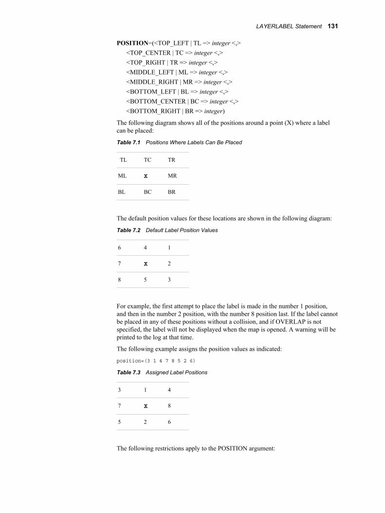
POSITION=(<TOP_LEFT | TL => integer <,><TOP_CENTER | TC => integer <,><TOP_RIGHT | TR => integer <,><MIDDLE_LEFT | ML => integer <,><MIDDLE_RIGHT | MR => integer <,><BOTTOM_LEFT | BL => integer <,><BOTTOM_CENTER | BC => integer <,><BOTTOM_RIGHT | BR => integer)
The following diagram shows all of the positions around a point (X) where a labelcan be placed:
Table 7.1 Positions Where Labels Can Be Placed
TL TC TR
ML X MR
BL BC BR
The default position values for these locations are shown in the following diagram:
Table 7.2 Default Label Position Values
6 4 1
7 X 2
8 5 3
For example, the first attempt to place the label is made in the number 1 position,and then in the number 2 position, with the number 8 position last. If the label cannotbe placed in any of these positions without a collision, and if OVERLAP is notspecified, the label will not be displayed when the map is opened. A warning will beprinted to the log at that time.
The following example assigns the position values as indicated:
position=(3 1 4 7 8 5 2 6)
Table 7.3 Assigned Label Positions
3 1 4
7 X 8
5 2 6
The following restrictions apply to the POSITION argument:
LAYERLABEL Statement 131
• If the keywords, for example, TOP_LEFT, are omitted and only the integer valuespecified, the values are assigned in left-to-right, top-to-bottom sequence.However, all eight of the values are required.
• The OFFSET= option has no effect on this form of the POSITION option. If it isencountered, it is ignored.
• Duplicate numbers are not allowed. You cannot have two locations numbered as5. The allowed integer values are 1-8, inclusive.
• The position values are stored in the map entry. There is no need to use them inmultiple LAYERLABEL statements. The last POSITION= values specified willbe the ones used to determine the locations for the point label when the map isopened.
ROW=integerspecifies a particular label in the data set to update, replace, delete or print.Restriction: The ROW= option is not valid for the CREATE operation.
SAS_VARIABLE=variable-namespecifies a variable in the map's chains data set that is used to create labels onfeatures in a specific map layer. The label for each feature in the specified layer iscreated by first determining the row number of each map feature to be labeled. Thevalue of the variable for that row is then used as the label for that feature. Forexample, the chain whose row number in the chains data set is 35 would be labeledwith the variable's value from row 35. The following restrictions apply to theSAS_VARIABLE argument:
• SAS_VARIABLE cannot be used with COMPOSITE orATTRIBUTE_VARIABLE options.
• MAP=map-entry is required because the map entry contains the spatial data setnames.
• The specified variable must already exist in the chains data set.
TEXT='string'specifies the text for a literal label, that is, one not associated with a specific maplayer. For REPLACE, UPDATE, DELETE or CONTENTS operations, stringspecifies a search string used to locate a specific target label if ROW= is not present.When TEXT='string' is used to search for a label, string is case sensitive, and anexact match to the value of the search string must be found. For example,TEXT='Paris' will ignore a label having PARIS as its text. It will also ignore a labelhaving 'Paris Metro' as its text.
If ROW= and TEXT= are both used in a REPLACE or UPDATE statement, the'string' entered with TEXT is not a search string. It becomes a replacement string forthe label at the specified ROW number.
TRANSPARENT | NOTRANSPARENTcontrols whether map features show through the label's bounding box.
TRANSPARENTenables the map features to show through the label's bounding box.
NOTRANSPARENTblocks the display of map features within the label's rectangular bounding box.
These options apply to text labels and image labels stored as catalog entries.They have no effect on image labels stored in an external file.
Default: TRANSPARENT
132 Chapter 7 • The GIS Procedure
MAP StatementDisplays information about the contents of a map entry, creates a new map entry, replaces an existing mapentry, modifies the characteristics of a previously created map entry, or deletes a map entry.
SyntaxMAP operation <libref.catalog.>map-entry </ options>;
Summary of Optional Arguments
ACTION=(action-arguments)specifies one or more action definitions for the map.
AGGREGATE | DISAGGREGATEcontrols how polygonal areas with identical ID values are treated.
ATTRIBUTE=(attribute-arguments)copies, deletes, or updates data links between the chains data set and attributedata sets.
CARTESIAN | LATLONspecifies the coordinate system used for the displayed spatial data.
CBACK=colorspecifies the background color of the map.
COVERAGE=<libref.catalog.>coverage-entryspecifies the coverage entry to which the map refers.
DEGREES | RADIANS | SECONDSspecifies the coordinate units for the displayed spatial data when thecoordinate system is geographic.
DESCRIPTION='string'specifies a description for the map.
DETAILS | NODETAILSspecifies whether detail coordinates are read for the entire map.
FORCEspecifies that existing actions or attribute links might be overwritten duringcopy operations.
IMAGEMAP=(HTML=(layer-links | ) DEFAULT=link-name)provides details for building an HTML version of a GIS map through ODS.
LABEL=<libref.>data-set | NONE | DELETE| HIDEALL | UNHIDEALLassigns or removes the specified label data set reference to the map.
LAYERS+=(<libref.catalog.>layer-entry-1<, …, <libref.catalog.>layer-entry-n>)specifies a list of layer (GISLAYER) entry names that are added to the map'scurrent layer list.
LAYERS=(<libref.catalog.>layer-entry-1<, …, <libref.catalog.>layer-entry-n>)specifies a list of layer (GISLAYER) entry names that define layers in themap entry
LAYERS-=(<libref.catalog.>layer-entry-1<, …, <libref.catalog.>layer-entry-n>)specifies a list of layer (GISLAYER) entry names that are removed from themap's current layer list.
MAP Statement 133
LAYERSOFF+=(<libref.catalog.>layer-entry-1<, …, <libref.catalog.>layer-entry-n>)
adds the specified layer(s) to the LAYERSOFF list and deactivate any on-scale/off-scale settings for the specified layer(s).
LAYERSOFF-=(<libref.catalog.>layer-entry-1<, …, <libref.catalog.>layer-entry-n>)
removes the specified layer(s) from the LAYERSOFF list and deactivatesany on-scale/off-scale settings for the specified layer(s).
LAYERSOFF=(<libref.catalog.>layer-entry-1<, …, <libref.catalog.>layer-entry-n>) | _ALL_
specifies a layer (or list of layers) to be turned off for this map.LAYERSON+=(<libref.catalog.>layer-entry-1<, …, <libref.catalog.>layer-entry-n>)
adds the specified layer(s) to the LAYERSON list and deactivates any on-scale/off-scale settings for the specified layer(s).
LAYERSON-=(<libref.catalog.>layer-entry-1<, …, <libref.catalog.>layer-entry-n>)removes the specified layer(s) from the LAYERSON list and deactivates anyon-scale/off-scale settings for the specified layer(s).
LAYERSON=(<libref.catalog.>layer-entry-1<, …, <libref.catalog.>layer-entry-n>)| _ALL_
specifies a list of layer (GISLAYER) catalog entries that will be turned on forthis map.
LEGEND=HIDEALL | UNHIDEALL | REMOVALLhides, displays, or removes map legends.
MULT=multiplier-valuespecifies a constant integer value by which spatial data coordinates aremultiplied when the data are displayed.
NOWARNspecifies that messages are not to be issued about actions or attribute linksthat are not found during deletion.
RENAME_LAYER old-name = new-namechanges the name of an existing layer in the map that is being updated.
SELECT+=(<libref.catalog.>layer-entry-1<, …, <libref.catalog.>layer-entry-n>)adds layers to the current list of selectable layers.
SELECT=(<libref.catalog.>layer-entry-1<, …, <libref.catalog.>layer-entry-n>)lists the layers to be selectable when the map opens.
SELECT-=(<libref.catalog.>layer-entry-1<, …, <libref.catalog.>layer-entry-n>)removes layers from the current list of selectable layers.
UNSELECT+=(<libref.catalog.>layer-entry-1<, …, <libref.catalog.>layer-entry-n>)adds layers to the current list of unselectable layers.
UNSELECT=(<libref.catalog.>layer-entry-1<, …, <libref.catalog.>layer-entry-n>)lists the layers to be unselectable when the map opens. All other layers willbe selectable.
UNSELECT-=(<libref.catalog.>layer-entry-1<, …, <libref.catalog.>layer-entry-n>)removes layers from the current list of unselectable layers.
Required Argument<libref.catalog.>map-entry
specifies the map entry that you want to create, delete, replace, or update. The map-name value must conform to the following rules for SAS names:
• The name can be no more than 32 characters long.
134 Chapter 7 • The GIS Procedure

• The first character must be a letter or underscore (_). Subsequent characters canbe letters, numeric digits, or underscores. Blanks are not permitted.
• Mixed-case names are honored for presentation purposes. However, because anycomparison of names is not case-sensitive, you cannot have two names that differonly in case (for example, State and STATE are read as the same name).
If you specify a one-level name, the map entry is assumed to be in the catalog that isspecified in the PROC GIS statement or in the most recently issued CATALOGstatement. An error occurs if no catalog has previously been specified.
OperationsCONTENTS
prints information about the specified map entry to the Output window, including thefollowing items:
• a list of the data objects (coverage and layer entries and label data set) thatcompose the map entry
• details of the spatial database as provided by the COVERAGE CONTENTS andSPATIAL CONTENTS statements
• details of the layer definitions as provided by the LAYER CONTENTS statement
• lists of the projection method that is used to display the map
• a list of associated data sets and link names
• a list of the GIS actions that have been defined for the map
• a list of legend definitions for the map
No additional arguments (other than the map-entry name) are used with thisoperation. An error occurs if the specified map entry does not exist.
CREATEcreates a new map entry that defines a map that can be displayed in the GIS Mapwindow.
An error occurs if a map entry with the specified name already exists. The MAPCREATE statement does not overwrite existing map entries. Use MAP REPLACE tooverwrite an existing entry.
For a MAP CREATE statement, you must also specify the COVERAGE= andLAYERS= arguments.
DELETEremoves the specified map entry. No additional arguments (other than the map entryname) are used with this operation. An error occurs if the specified map entry doesnot exist.
For the DELETE operation, you can also specify the special value _ALL_ for themap entry name argument to delete all map entries in the current catalog.CAUTION: Use DELETE with care. The GIS procedure does not prompt you to
verify the request before deleting the map entry. Be especially careful when youuse _ALL_.
PRESENTcreates an HTML file to display a GIS map on the Web.
creates an HTML file to display a GIS map on the Web using ODS and theIMAGEMAPS option.
MAP Statement 135
REPLACEoverwrites the specified map entry or creates a new entry if an entry with thespecified name does not exist. The REPLACE operation has the effect of cancelingthe previously issued CREATE operation for the specified map entry.
For a REPLACE operation, you must also specify the COVERAGE= and LAYERS=options.
UPDATEmodifies the specified map entry by applying new values for specified arguments.An error occurs if there is no existing map entry with the specified name.
OptionsWhen you specify CREATE, REPLACE, or UPDATE for the MAP operation, you canspecify one or more of the following options following the map-entry name. Separate thelist of options from the map entry name argument with a slash (/).
ACTION=(action-arguments)specifies one or more action definitions for the map. The following list containsdescriptions of the ACTION arguments.
COMMAND='command-name' | variablespecifies the commands to be run when either a COMMAND or aSYSTEMCOMMAND action is executed in the map. Valid values are:
'command-1<;…; command-n;>'To specify commands explicitly, enclose them in quotation marks. Separatemultiple commands with semicolons.
variablespecifies the variable containing the commands in the linked data set.
The COMMAND= parameter is used only by the COMMAND andSYSTEMCOMMAND type actions and is a required argument. If the action typeis COMMAND, COMMAND= refers to a SAS command. If the action type isSYSTEMCOMMAND, it refers to a host operating system command.
COPYcopies existing actions from one map entry to another. Specify the map entry thatcontains the actions to be copied with the FROM=map-entry argument. Theactions are copied to the map that is specified in the MAP statement.
Specify the actions to be copied with the NAME=action-name argument. If youspecify NAME=_ALL_ you copy all actions in the specified map. Existingactions in the map to be updated are not overwritten unless you specify theFORCE option in the MAP statement.
CREATEadd a new action to the map.
DELETEremoves an existing action from the map entry. Specify the action to be deletedwith the NAME=action-name argument. You can specify NAME=_ALL_ todelete all actions. Use the NOWARN argument in the MAP statement tosuppress messages when an action is not found.CAUTION: Use DELETE with care. The GIS procedure does not prompt you to
verify the request before it deletes the action from the map.
FORMULA=<libref.>catalog.entry.typespecifies a formula catalog entry to be used by an FSVIEW action. AFORMULA entry must be a fully qualified three- or four-level name. If the name
136 Chapter 7 • The GIS Procedure
is three levels, it is assumed to be in the WORK library. FORMULA is used onlyby the VIEW type action, and it is an optional argument.
FROM=map-entryused with the ACTION argument COPY operation, FROM= specifies the sourcemap entry that contains actions to be copied. Specify the actions to be copiedfrom the map with the NAME=action-name argument.
IMAGEVAR=variable-namespecifies the name of the variable in the LINK= data set which contains theimage to display for the current selected feature. IMAGEVAR is used only by anIMAGE type action, and it is a required argument.
LINK=link-namespecifies an attribute data set link. If the link does not exist, you can create it inthe same MAP statement with the ATTRIBUTE= option. A LINK is required forall action types except a SPATIALINFO action.
MAPVAR=variable-namespecifies the name of the variable in the LINK= data set containing the three-level name of the map to be opened when a particular feature is selected.MAPVAR is used only by the TYPE=DRILLDOWN type action and is arequired argument.
NAME=action-name | _ALL_specifies the action to be copied, deleted, or updated. Action-name identifies asingle action, while _ALL_ specifies all actions.Restriction: You cannot specify NAME=_ALL_ if you are using ACTION
UPDATE with the RENAME argument.
OUT=data-set-namespecifies an output data set. OUT= is required for DATA and PROGRAMactions. It is optional for COMMAND and SYSTEMCOMMAND type actions.
OUTMODE=REPLACE | APPEND | APPEND_NEWspecifies how to the action writes to the OUTPUT data set.
REPLACEoverwrites the existing data set.
APPENDwrites the observations to the end of the existing data set.
APPEND_NEWcreates a new data set the first time the action is executed, and appends to thisdata set each additional time the action is executed.
Default: REPLACE
REDISTRICT=variable-nameopens the Redistricting window to adjust totals in adjoining areas.
REDISTRICTLAYER=layer-namespecifies the name of the polygonal layer to be themed by the redistricting action.REDISTRICTLAYER= is used only by the REDISTRICT type action and is arequired argument.
REDISTRICTVAR=variable-namespecifies the name of the variable in the LINK data set upon which theredistricting will be based. REDISTRICTVAR= is used only by theREDISTRICT type action and is a required argument.
MAP Statement 137
RENAME=new-action-namerenames the action that is specified in the NAME=action-name for UPDATE.Restriction: You cannot specify RENAME if you have also specified
NAME=_ALL_.
REPLACEreplaces the named action, or, if it does not exist, creates a new action with thatname.
SCREEN=<libref.>catalog.entry.typespecifies a screen catalog entry to be used by an FSBROWSE action. ASCREEN entry must be a fully qualified three- or four-level name. If the name isthree levels, it is assumed to be in the WORK library. SCREEN is used only bythe BROWSE type action, and it is an optional argument.
SOURCE='filename' | <libref.>catalog.entry.type | filerefspecifies the location of the source code for a PROGRAM type action. Thefollowing are valid locations:
'filename'an external file containing SAS code. The host-path filename must beenclosed in quotation marks.
<libref.>catalog.entry.typethe three- or four-level name of a catalog entry containing the SAS code. Athree-level name is assumed to be in the WORK library. Valid values for typeare SOURCE and SCL.
filerefa one-level name is assumed to be a SAS fileref. If the fileref does not exist,the action is created, and a warning is printed to the log.
The SOURCE parameter is used only by a PROGRAM type action and is arequired argument.
SUMMARYVAR=(variable-1<, …, variable-n> | _ALL_)specifies a list of NUMERIC variables to display in the Redistricting windowwhen a REDISTRICT type action is executed. Only NUMERIC variables arevalid because redistricting sums the values for each new district. SpecifyingSUMMARYVAR=(_ALL_) displays sums for every numeric variable.Default: _ALL_Restriction: SUMMARYVAR= is used only by the REDISTRICT action.
TYPEused with CREATE to select an action type. The following are valid arguments:
BROWSEopens an FSBROWSE window on a data set.
COMMANDruns a SAS command.
DATAsubsets the current selections and write attribute data into a data set.
DRILLDOWNopens another map associated with the current feature.
IMAGEdisplays an image associated with the selected map feature.
PROGRAMcreates a data set and run a SAS program against its observations.
138 Chapter 7 • The GIS Procedure
REDISTRICTopens the Redistricting window to adjust totals in adjoining areas.
SPATIALINFOdisplays the current feature in the Spatial Information window.
SYSTEMCOMMANDruns a command from the host operating system.
VIEWopens an FSVIEW window on a data set.
UPDATEmodifies existing actions in the map that is being updated. Specify the action tobe updated with the NAME=action-name argument. You specifyNAME=_ALL_ to update all actions. NAME= is required for UPDATE.
If you specify a single action, you can use the RENAME=new-action-nameargument to change the link name. You cannot use RENAME if you specifyNAME=_ALL_.
You can also change the action's execution settings with the WHEN= argument.
WHEN=OFF | IMMEDIATE | DEFERREDused with UPDATE to change the execution setting of the specified action.
OFFThe action is not executed when a layer feature is selected.
IMMEDIATEThe action is executed as soon as a layer feature is selected.
DEFERREDThe action's execution must be performed explicitly after a layer feature hasbeen selected.
AGGREGATE | DISAGGREGATEcontrols how polygonal areas with identical ID values are treated.
AGGREGATEsets a flag so that polygonal areas with identical ID values are considered as one.For example, if you are selecting from the STATE layer and click on NorthCarolina, all the Outer Banks islands are also selected.
DISAGGREGATEsets a flag so that polygonal areas with identical ID values are treatedindependently. For example, if you are selecting from the STATE layer of theNorth Carolina map and click on Emerald Isle, only that one island gets selected.
Default: DISAGGREGATE
ATTRIBUTE=(attribute-arguments)copies, deletes, or updates data links between the chains data set and attribute datasets. The following are the arguments used with ATTRIBUTE:
COMPOSITE=(composite-name-1<, …, composite-name-n>)lists spatial composite names when you create a new key link. These compositesare paired with the attribute data set variables that are named in the DATAVAR=option. If the composite names and the data set variable names are the same, youcan just specify them once with either the COMPOSITE= or DATAVAR= lists,and those names will be used for both.
MAP Statement 139
COPYcopies existing attribute data links from one map entry to another. Specify themap entry that contains the links to be copied by using the FROM=map-entryargument. The links are copied to the map that is specified in the MAP statement.
Specify the link to be copied with the NAME=link-name option. If you specifyNAME=_ALL_, you copy all links in the specified map. Existing links in themap to be updated are not overwritten unless you specify the FORCE option inthe MAP statement.
CREATEadds a new attribute data link to the map.
DATASET=libref.data-set-namespecifies the attribute data set when you create a new key link.
DATAVAR=(variable-name-1 <, …, variable-name-n>)lists attribute data set variables when you create a new key link. These variablesare paired with the spatial composites that are named in the COMPOSITE=option. If the data set variable names and the composite names are the same, youcan just specify them once with either the COMPOSITE= or DATAVAR= lists,and those names will be used for both.
DELETEremoves an existing attribute data link from the map entry. Specify the link to bedeleted with the NAME=link-name argument. If you specify NAME=_ALL_,you delete all data links. Use the NOWARN option in the MAP statement tosuppress messages when a link is not found. This does not delete the attributedata set, only the link.CAUTION: Use DELETE with care. The GIS procedure does not prompt you to
verify the request before it deletes the attribute data link from the map.
FROM=map-entryused with the ATTRIBUTE COPY operation, specifies the map entry thatcontains data links to be copied. Specify the links to be copied from the map withthe NAME=link-name argument.
NAME=link-name | _ALL_specifies the attribute data link to be copied, deleted, or updated. Link-nameidentifies a single data link, while _ALL_ specifies all data links.Restriction: You cannot specify NAME=_ALL_ if you are using UPDATE with
the RENAME argument.
RENAME=new-link-namerenames the link that is specified in NAME=link-name for the UPDATEoperation.Restriction: You cannot use the RENAME option if you have also specified
NAME=_ALL_.
UPDATEmodifies existing data links in the map that is being updated. Specify the link tobe updated with the NAME=link-name argument. Specify NAME=_ALL_ toupdate all data links. NAME= is required for the UPDATE operation.
If you specify a single link, you can use the RENAME=new-link-name argumentto change the link name. You cannot use RENAME if you specifyNAME=_ALL_.
CARTESIAN | LATLONspecifies the coordinate system used for the displayed spatial data.
140 Chapter 7 • The GIS Procedure
CARTESIANdata is in an arbitrary rectangular (plane) coordinate system
LATLONdata is in a geographic (spherical) coordinate system.
Default: LATLONRestriction: The map entry must use the same coordinate system as the spatial entry
from which the map is derived. If the spatial entry specifies the CARTESIANcoordinate system, then you must also specify the CARTESIAN argument for theMAP statement. If the spatial entry specifies the LATLON coordinate system,then you must also specify the LATLON argument for the MAP statement.
CBACK=colorspecifies the background color of the map. The color value must be one of thefollowing:
• a SAS color name
• an RGB color code in the form CXrrggbb
• an HLS color code in the form Hhhhllss
• a gray-scale color code in the form GRAYnn
Default: WHITESee: For more information about color naming schemes, see “Specifying Colors in
SAS/GRAPH Programs” in SAS/GRAPH: Reference.
COVERAGE=<libref.catalog.>coverage-entryspecifies the coverage entry to which the map refers. The coverage determines thegeographic extent of the map.Note: The COVERAGE= argument is required when you use the CREATE or
REPLACE operation.
DEGREES | RADIANS | SECONDSspecifies the coordinate units for the displayed spatial data when the coordinatesystem is geographic (LATLON).
The unit system that you select defines the allowable range for coordinate values.For example, if you specify DEGREES, then all X coordinate values must be in therange -180 to 180, and all Y coordinate values must be in the range -90 to 90.
DEGREESunits for LATLON data are measured in decimal degrees.
RADIANSunits for LATLON data are measured in radians.
SECONDSunits for LATLON data are measured in seconds.
Default: RADIANS
DESCRIPTION='string'specifies a descriptive phrase up to 256 characters long that is stored in thedescription field of the GISMAP entry.Default: Blank
DETAILS | NODETAILSspecifies whether detail coordinates are read for the entire map.Default: NODETAILS
MAP Statement 141
Interaction: You can use the LAYER statement's DETAILS and DETAILON=options to control the display of detail coordinates for a particular layer. TheMAP statement's DETAILS option overrides the LAYER statement's DETAILSoption.
FORCEspecifies that existing actions or attribute links might be overwritten during copyoperations. Use this argument with the COPY argument in the ACTION orATTRIBUTE argument.
IMAGEMAP=(HTML=(layer-links | ) DEFAULT=link-name)provides details for building an HTML version of a GIS map through ODS. ThePRESENT operation uses the SAS Output Delivery System (ODS) to generate anHTML page with aGIF image of the map. The GIF image can be a static image orcan contain clickable map points or polygons. Each selectable map feature isassociated with a URL. The URL addresses are contained in one or more variables ina SAS data set that is linked to the map.
The following options are used to specify the linked data set and the URL-relatedvariables for specific map layers:
_ALL_=variable-namedeclares that all of the selectable map layers use the URLs stored in the specifieddata set variable.
HTML=(layer-entry–1 = variable-name-1<, …, layer-entry–n = variable-name-n>)associates different URL-related variables with specific layers.
DEFAULT=link-namespecifies the link name for the attribute data set that contains the URL-relatedvariables.
Restriction: The IMAGEMAP= argument is valid only with the PRESENToperation in the MAP statement.
LABEL=<libref.>data-set | NONE | DELETE| HIDEALL | UNHIDEALLassigns or removes the specified label data set reference to the map. If the mapalready has a label data set, the original is deassigned. However, it is not overwritten.
LABEL=<libref.>data-setassigns the specified data set reference to the map entry. An error occurs if thespecified data set does not exist. If the libref is not specified, the default WORKlibrary is used.
LABEL=NONEunassigns the current label data set from the map entry, but the data set is notdeleted.
LABEL=DELETEunassigns the current label data set from the map entry, and deletes the data set.
LABEL=HIDEALLhides all of the labels in the target map. HIDEALL does not remove the labeldata set reference from the map entry.
LABEL=UNHIDEALLdisplays all of the labels in the target map. UNHIDEALL does not display labelsattached to layers that are not displayed, nor does it display labels that would notbe displayed at the current scale of the map.
142 Chapter 7 • The GIS Procedure
LAYERS=(<libref.catalog.>layer-entry-1<, …, <libref.catalog.>layer-entry-n>)specifies a list of layer (GISLAYER) entry names that define layers in the map entryIf the map entry already contains a list of layers, they are replaced by the specifiedlayers.Requirement: The LAYERS= argument is required when you use the CREATE or
REPLACE operation.
LAYERS+=(<libref.catalog.>layer-entry-1<, …, <libref.catalog.>layer-entry-n>)specifies a list of layer (GISLAYER) entry names that are added to the map's currentlayer list.
LAYERS-=(<libref.catalog.>layer-entry-1<, …, <libref.catalog.>layer-entry-n>)specifies a list of layer (GISLAYER) entry names that are removed from the map'scurrent layer list. The layer entries are not deleted. They remain in their respectivecatalogs.
LAYERSON=(<libref.catalog.>layer-entry-1<, …, <libref.catalog.>layer-entry-n>) |_ALL_
specifies a list of layer (GISLAYER) catalog entries that will be turned on for thismap. All other layers will be turned off. Any on-scale/off-scale settings aredeactivated. Specifying LAYERSON=(_ALL_) turns all layers on.
The following information applies to the LAYERSON and LAYERSOFF options:
• If a layer in any of the lists does not exist in the map, a warning is issued and thatlayer is ignored. (A missing layer does not end the current RUN-groupprocessing.) Each layer is evaluated individually, so if other layers are valid theyare toggled appropriately.
• If a layer is in both the LAYERSON list and the LAYERSOFF list, this conditiongenerates a warning and ends that RUN-group.
• If one of the LAYERS options is specified in addition to LAYERSON orLAYERSOFF, the LAYERS parameters are processed first. Therefore, if a layeris removed from the map by using the LAYERS parameter, it cannot bereferenced in a LAYERSON or LAYERSOFF parameter in that same statement.This action generates a warning, but the RUN-group processing does not stop.
• If both LAYERSON and LAYERSOFF are used in the same statement, bothparameters must specify -=, +=, or both. Specifying both LAYERSON= andLAYERSOFF= in the same statement causes a conflict, and therefore is notallowed.
• The _ALL_ option cannot be mixed with layer names, that is, _ALL_ mustappear by itself.
• _ALL_ cannot be used with either the += or the -= operators.
LAYERSON+=(<libref.catalog.>layer-entry-1<, …, <libref.catalog.>layer-entry-n>)adds the specified layer(s) to the LAYERSON list and deactivates any on-scale/off-scale settings for the specified layer(s). See the LAYERSON= option on page 143for more information about restrictions and interactions.
LAYERSON-=(<libref.catalog.>layer-entry-1<, …, <libref.catalog.>layer-entry-n>)removes the specified layer(s) from the LAYERSON list and deactivates any on-scale/off-scale settings for the specified layer(s). See the LAYERSON= option onpage 143 for more information about restrictions and interactions.
MAP Statement 143

LAYERSOFF=(<libref.catalog.>layer-entry-1<, …, <libref.catalog.>layer-entry-n>) |_ALL_
specifies a layer (or list of layers) to be turned off for this map. All other layers areturned on. Any on-scale/off-scale settings are deactivated. SpecifyingLAYERSOFF=(_ALL_) turns all layers off.
See the LAYERSON= option on page 143 for more information about restrictionsand interactions.
LAYERSOFF+=(<libref.catalog.>layer-entry-1<, …, <libref.catalog.>layer-entry-n>)adds the specified layer(s) to the LAYERSOFF list and deactivate any on-scale/off-scale settings for the specified layer(s). See the LAYERSON= option on page 143for more information about restrictions and interactions.
LAYERSOFF-=(<libref.catalog.>layer-entry-1<, …, <libref.catalog.>layer-entry-n>)removes the specified layer(s) from the LAYERSOFF list and deactivates any on-scale/off-scale settings for the specified layer(s). See the LAYERSON= option onpage 143 for more information about restrictions and interactions.
LEGEND=HIDEALL | UNHIDEALL | REMOVALLhides, displays, or removes map legends.
HIDEALLcauses all existing legends to be hidden (not displayed) when the map is opened.
UNHIDEALLcauses all existing legends to be displayed when the map is opened.
REMOVEALLremoves all of the existing legends from the map.CAUTION: This behavior is immediate and permanent. You cannot restore the
legends and will have to recreate them.
Restrictions:The LEGEND= option is valid only in with the UPDATE operation in the MAPstatement.Only one of the LEGEND= options can be specified at a time.
MULT=multiplier-valuespecifies a constant integer value by which spatial data coordinates are multipliedwhen the data are displayed. If the unit multiplier is too large, it is recomputed whenthe map is opened, and a note is printed to the SAS log showing the new value. Ifyour map opens and appears to be empty, your MULT value might be too small.Default: 1E7
NOWARNspecifies that messages are not to be issued about actions or attribute links that arenot found during deletion. Use this argument when you specify the DELETEoperation in the ACTION or ATTRIBUTE argument.
RENAME_LAYER old-name = new-namechanges the name of an existing layer in the map that is being updated. Thisargument also changes the name of the layer entry in the catalog.
If other maps use the renamed layer, you must issue a MAP UPDATE statement forthose maps as well.
SELECT=(<libref.catalog.>layer-entry-1<, …, <libref.catalog.>layer-entry-n>)lists the layers to be selectable when the map opens. All other layers will beunselectable.
144 Chapter 7 • The GIS Procedure
SELECT+=(<libref.catalog.>layer-entry-1<, …, <libref.catalog.>layer-entry-n>)adds layers to the current list of selectable layers.
SELECT-=(<libref.catalog.>layer-entry-1<, …, <libref.catalog.>layer-entry-n>)removes layers from the current list of selectable layers.
UNSELECT=(<libref.catalog.>layer-entry-1<, …, <libref.catalog.>layer-entry-n>)lists the layers to be unselectable when the map opens. All other layers will beselectable.
UNSELECT+=(<libref.catalog.>layer-entry-1<, …, <libref.catalog.>layer-entry-n>)adds layers to the current list of unselectable layers.
UNSELECT-=(<libref.catalog.>layer-entry-1<, …, <libref.catalog.>layer-entry-n>)removes layers from the current list of unselectable layers.
DetailsA map entry is a SAS catalog entry of type GISMAP that defines the displayed featuresof a map. The definition specifies which layers the map contains and which coverage ofthe spatial database is used. The map entry also stores legend definitions and actiondefinitions for the map, information about the projection system used to display the map,the name of the data set that contains labels for map features, and the names of any otherassociated SAS data sets.
Examples
Example 1: Define a New MapThe following code fragment creates an entry named STORES of type GISMAP in thecurrent catalog. The map is based on the coverage defined in the GISCOVER entrynamed MALL in the current catalog and uses the GISLAYER entries STORE, FIRE,INFO, PHONE, and RESTROOM in the current catalog.
map create stores / coverage=mall layers=(store, fire, info, phone, restroom);run;
Example 2: Update an Existing Map DefinitionThe following code fragment updates the MAPS.USA.USA.GISMAP entry to use detaildata when the map is displayed:
map update maps.usa.usa / details;run;
Example 3: Copy Attribute Data Set LinksThe following code fragment copies the SIMPLUSR attribute link fromGISSIO.SIMPLUS.SIMPLE to WORK.SIMPLE.SIMPLE:
proc gis; map update work.simple.simple / attribute=(name=simplusr copy from=gissio.simplus.simple);run;
MAP Statement 145
MAPLABEL StatementApplies, modifies, or deletes labels on a map.
SyntaxMAPLABEL operation <options>;
Summary of Optional Arguments
_ALL_applies an operation to all labels.
ATTACH_TO=MAP | WINDOWcontrols the label positioning and is a required argument.
COLOR=color-name | CXrrggbbspecifies the text color.
DATASET=<libref.>data-set-namespecifies the label data set to which new labels are appended.
FONT=font-name | DEFAULTspecifies the font used in the label.
FORCEreplaces the existing label data set reference in a map when both DATASET=and MAP= are specified.
FRONT | BACKcontrols how an image label is drawn relative to map features.
IMAGE='path-name' | <libref.>catalog.entry<.IMAGE> | filerefspecifies the location of an image to use as an image label on the map.
MAP=<libref.catalog.>map-entryindicates the map entry on which to display the labels.
OFFSCALE=(scale <units>)specifies a map scale at which the label is turned on off when the map view iszoomed.
OFFSET=(<x<units>> <, y<units>> <, units>)specifies the distance to move the entire label.
ONSCALE=(scale <units>)specifies a map scale at which the label is turned on when the map view iszoomed.
ORIGIN=(<x<unitx>> <, y<units>> <, units>)specifies the horizontal and vertical coordinates for the label.
OVERLAP | NOOVERLAPspecifies how labels are treated when they overlap.
POSITION=(<TOP | MIDDLE | BOTTOM> <LEFT | CENTER | RIGHT>)assigns a single label to a position on the map relative to the map's boundingbox.
ROW=integerspecifies the label in the data set to which the operation applies.
TEXT='string'specifies the text for a literal label.
146 Chapter 7 • The GIS Procedure
TRANSPARENT | NOTRANSPARENTcontrols whether map features show though the label's bounding box.
OperationsCONTENTS
prints label information to the Output window. If you specify
• _ALL_, then every label not associated with a layer is printed.
• TEXT='string', then only labels matching that text are printed. The comparison iscase sensitive.
• ROW=integer, then only the label at that row is printed.
If no labels are output, a NOTE is printed to the log.
CREATEcreates a new label or labels. Unlike CREATE operations for other PROC GISstatements, duplicate labels are allowed.
DELETEremoves the specified labels and, depending on which optional arguments arespecified, possibly deletes the label data set. The only valid optional arguments forDELETE are DATASET=, MAP=, LAYER=, TEXT=, IMAGE=, ROW=, and_ALL_. Any others will be ignored.
If you specify
• DATASET=data-set-name as the only argument, then the label data set isdeleted.
• MAP=map-entry as the only argument, then the label data set reference isremoved from the map entry, and the data set is deleted. If you do not specifyMAP=, and all of the rows in the label data set are deleted, you are cautioned thatany maps using the deleted data set will generate a WARNING when opened.
• ROW=, then only the label at that data set row is deleted. ROW= and _ALL_ arenot allowed together. If you use ROW= and TEXT=, the TEXT= is ignored andthe label at that row is deleted.
• TEXT='string', then every label literal having this exact string is removed fromthe label data set.
Note: Literal labels are those not associated with a specific layer.
• IMAGE=, then the specified image is deleted.
• _ALL_, then every label that is not associated with a layer is removed from thelabel data set.
Either DATASET= or MAP= is required or no deletions can occur.
Any DELETE operation that deletes all of the rows in the label data set also causesthe data set to be deleted. If a data set is deleted, a NOTE is printed to the log. IfMAP= is present and the label data set is deleted, the reference to the data set withinthe map entry is removed.
A note is printed in the log upon completion of a successful deletion.
REPLACEreplaces an existing label specified by TEXT='string' of ROW=. If the label does notexist, a CREATE is performed.
MAPLABEL Statement 147
UPDATEmodifies an existing label.
OptionsSeparate the list of options from the catalog entry name with a slash (/).
_ALL_affects the behavior of the following operations:
• In a CONTENTS operation, _ALL_ prints every label that is not associated witha layer to the Output window.
• In a DELETE operation, _ALL_ deletes every label that is not associated with alayer.
_ALL_ has no effect on CREATE, REPLACE, or UPDATE operations. If _ALL_ isdetected, it is ignored.
_ALL_ cannot be used in the same statement with ROW= or TEXT= options.
ATTACH_TO=MAP | WINDOWcontrols the label positioning and is a required argument.
MAPThe label is attached to a location on the map. As you move the map in thewindow, the label moves with the map.
WINDOWThe label is attached to the map window. It remains fixed relative to the windowas you move the map in the window.
COLOR=color-name | CXrrggbbspecifies the text color.
color-nameis a SAS color-name, for example GREEN or RED.
CXrrggbbis an RGB color, for example CX23A76B.
Default: BLACK.See: For more information about color-naming schemes, see “Specifying Colors in
SAS/GRAPH Programs” in SAS/GRAPH: Reference.
DATASET=<libref.>data-set-namespecifies the label data set to which new labels are appended. If the data set does notexist, it is created.
If you specify a one-level data set name, the WORK library is assumed. If youspecify both DATASET= and MAP=, and the map already references a label dataset, the data set names are compared. If they are not the same and FORCE was notspecified, a warning is printed, and the run group is terminated.
FONT=font-name | DEFAULTspecifies the font used in the label.
font-namespecifies a font for the label text.Default: If the specified font is not found when the map is opened, the default
system font is substituted and a note is printed to the log.Example:
148 Chapter 7 • The GIS Procedure
font='Times New Roman-12pt-Roman-Bold'font='Display Manager font'font='Sasfont (10x15) 10pt-9.7pt-Roman-Normal'
DEFAULTassigns the default font to the label.
FORCEreplaces the existing label data set reference in a map when both DATASET= andMAP= are specified. If the map already references a label data set, its data set nameis compared to the name specified with DATASET=. If they are not the same, theFORCE option causes the map's label data set reference to be overwritten and a noteprinted to the log. The map's original label data set is not deleted.
FRONT | BACKcontrols how an image label is drawn relative to map features.
FRONTcauses an image label to be drawn over the map features.
BACKcauses an image label to be drawn beneath the map features.
Default: FRONTNote: These options do not apply to text labels.
IMAGE='path-name' | <libref.>catalog.entry<.IMAGE> | filerefspecifies the location of an image to use as an image label on the map.
'path-name'specifies a host directory path to an image file.Example:
image='C:\My SAS Files\photo.gif'
<libref.>catalog.entry<.IMAGE>specifies an IMAGE type catalog entry for the image label.
If you omit the library name from the statement, the WORK library is the default.
filerefspecifies an active SAS fileref that points to an external file for an image label.The host directory path for this fileref is written to the label data set, not to thefileref.
MAP=<libref.catalog.>map-entryindicates the map entry on which to display the labels. If you indicate a one-levelname, the map entry is assumed to be in the catalog that is specified in the PROCGIS statement or in the most recently issued CATALOG statement.
If the specified map entry already references a label data set, new labels areappended to that data set.
If the map entry does not reference a label data set, you must provide a label data setname with the DATASET= option. The labels are written to that data set, and thedata set is then assigned to the specified map.
For the MAPLABEL statement, either MAP= or DATASET= is required. If both arepresent and the map already has a label data set, its name must match the namespecified in the DATASET= option. One exception is if the FORCE option is alsoused. In that case, the label data set specified by DATASET= is assigned to the mapentry. The map's original label data set is unassigned but not deleted.
MAPLABEL Statement 149

OFFSET=(<x<units>> <, y<units>> <, units>)specifies the distance to move the entire label.
xis the number of units to move the label right (positive numbers) or left (negativenumbers).
yis the number of units to move the label up (positive numbers) or down (negativenumbers).
unitsis one of the following values:
PERCENT | PCTspecifies that the X and Y coordinate values are a percentage of the distancefrom the lower left corner of the map window to the label origin. When thewindow is resized, the label remains in the same relative location. Forexample, if both the X and Y coordinates are set to 50, then the label originremains in the center of the window. Negative values and values greater than100% are not allowed.
PIXELspecifies that the X and Y coordinate values are screen coordinates usingpixels. The lower left corner of the window is 0, 0. Negative values are notallowed. If a specified pixel value runs the label outside of the window, thelabel is shifted horizontally, vertically, or both to be just within the windowwhen the map is opened.
REALX and Y values are real-world coordinates based on the underlying spatialdata. Negative values can be used to signify the western or southernhemispheres if the spatial data contains them.
To set only the X offset, specify one value, with or without a following comma, as inthe following example:
offset = ( 10 real, )
To set both the X and Y offset, specify two values, with or without a commaseparating them, as in the following example:
offset = ( 20 pct, 40 pct )
To set only the Y offset, specify one value preceded by a comma, as in the followingexample:
offset = ( ,-30 pct )
OFFSET= is usually used in conjunction with POSITION= to adjust the position of alabel. Moves are relative to the location specified by POSITION=, withOFFSET=(0,0) representing the initial position. You can also apply OFFSET= to thedefault label position.
The following restrictions apply to the OFFSET= argument:
• When both ORIGIN and OFFSET are used, the same units must be specified forboth. If no units are specified in the OFFSET= arguments, the unit entered in theORIGIN= option is used.
• OFFSET= is unnecessary with ORIGIN= because ORIGIN= explicitly positionsthe label and requires no further adjustment. However, if you specify bothoptions, the values of OFFSET= are added to the values of ORIGIN=, and thelabel is positioned accordingly.
150 Chapter 7 • The GIS Procedure
• If the resulting location is outside of the GIS Map window, a warning is printedto the log when the map is opened. The label is moved to be within the window.
ONSCALE=(scale <units>)specifies a map scale at which the label is turned on when the map view is zoomed.
scalespecifies the map scale value at which the label is turned on.
unitsspecifies the units for the scale value.
real-units/map-unitsenables you to specify various combinations of units. Valid values are KM,M, CM, MI, FT, and IN. Real-units is typically KM, M, MI, or FT, and map-units is usually either CM or IN. Long forms of the unit names, for exampleKILOMETERS or INCH (singular or plural), are also acceptable.
METRICsets the scale units to KM/CM.
ENGLISHsets the scale units to MI/IN.
Default: METRIC
OFFSCALE=(scale <units>)specifies a map scale at which the label is turned on off when the map view iszoomed.
scalespecifies the map scale value at which the label is turned off.
unitsspecifies the units for OFFSCALE.
real-units/map-unitsenables you to specify various combinations of units. Valid values are KM,M, CM, MI, FT, and IN. Real-units is typically KM, M, MI, or FT, and map-units is usually either CM or IN. Long forms of the unit names, for exampleKILOMETERS or INCH (singular or plural), are also acceptable.
METRICsets the scale units to KM/CM.
ENGLISHsets the scale units to MI/IN.
Default: METRIC
ORIGIN=(<x<unitx>> <, y<units>> <, units>)specifies the horizontal and vertical coordinates for the label. ORIGIN= explicitlypositions the label anywhere on the map. Unlike the POSITION= location, the labelis not centered about this point. The lower left corner of the label is placed at thespecified ORIGIN location.
xspecifies the X coordinate (horizontal axis)
yspecifies the Y coordinate (vertical axis)
unitscan be one of the following values:
MAPLABEL Statement 151
PERCENT | PCTspecifies that the X and Y coordinate values are a percentage of the distancefrom the lower left corner of the map window to the label origin. When thewindow is resized, the label remains in the same relative location. Forexample, if both the X and Y coordinates are set to 50, then the label originremains in the center of the window. Negative values and values greater than100% are not allowed.
PIXELspecifies that the X and Y coordinate values are screen coordinates usingpixels. The lower left corner of the window is 0, 0. Negative values are notallowed. If a specified pixel value runs the label outside of the window, thelabel is shifted horizontally, vertically, or both to be just within the windowwhen the map is opened.
REALX and Y values are real-world coordinates based on the underlying spatialdata. Negative values can be used to signify the western or southernhemispheres if the spatial data contains them.
To set only the X coordinate, specify one value with or without a following comma,as in the following examples
origin=(10 pixels,)origin=(10 pixels)
To set both the X and Y coordinates, specify two values with or without a commaseparating them. The units can be specified for both X and Y or once at the end, as inthe following examples:
origin=(10 pct, 40 pct)origin=(10 pct 40 pct)origin=(10 40 pct)origin=(10, 40, pct)
To set only the Y coordinate, specify one value preceded by a comma, as in thefollowing example:
origin=(, 20 pct)
ORIGIN= overrides the POSITION= option if both options are present. Althoughusing the OFFSET= option with the ORIGIN= option is unnecessary, if you alsospecify OFFSET=, it is applied after the ORIGIN= request has been processed.
If the specified origin or origin plus offset is outside of the overall map boundingbox, a warning is printed to the log. No warning is issued if the label runs out of thebox, however.
OVERLAP | NOOVERLAPspecifies how labels are treated when they overlap.
OVERLAPAll labels that you create with the option will be displayed even if they conflictwith other labels.
NOOVERLAPSome of the conflicting labels will be suppressed until you zoom in more closely.
Default: NOOVERLAP
POSITION=(<TOP | MIDDLE | BOTTOM> <LEFT | CENTER | RIGHT>)assigns a single label to a position on the map relative to the map's bounding box. Ifthe label is attached to the map, the label position is determined using the spatial data
152 Chapter 7 • The GIS Procedure
bounding box, that is the upper, lower, right and left edges of the coverage extents. Ifthe label is attached to the window, the window edges are used.
The following arguments determine the vertical position of the label:
TOPplaces the label along the upper edge of the map or window.
MIDDLEplaces the label halfway between the top and bottom edges of the map orwindow.
BOTTOMaligns the label with the bottom edge of the map or window.
The following arguments determine the horizontal position of the label:
LEFTstarts the label at the left edge of the map or window.
CENTERplaces the label halfway between the left and right edges of the map or window.
RIGHTaligns the end of the label with the right edge of the map or window. The label iscentered horizontally and vertically at the computed position point. You canadjust the initial label position with the OFFSET= option.
ROW=integerspecifies a particular label in the data set to UPDATE, REPLACE, DELETE or printCONTENTS. Not valid for CREATE operations.
TEXT='string'specifies the text for a literal label. For REPLACE, UPDATE, DELETE orCONTENTS operations, string specifies a search string used to locate a specifictarget label. When TEXT='string' is used to search for a label, string is casesensitive, and an exact match to the value of the search string must be found. Forexample, TEXT='Paris' will ignore a label having PARIS as its text. It will alsoignore a label having 'Paris Metro' as its text.
If ROW= and TEXT= are both present in a REPLACE or UPDATE statement the'string' entered with TEXT= is not a search string. It becomes the new text for thelabel at the specified ROW number.
TRANSPARENT | NOTRANSPARENTcontrols whether map features show though the label's bounding box.
TRANSPARENTenables the map features to show though the label's bounding box.
NOTRANSPARENTblocks the display of map features within the label's rectangular bounding box.
These options apply to text labels and image labels stored as catalog entries.They have no effect on image labels stored in an external file.
Default: TRANSPARENT
COPY StatementCopies a SAS/GIS catalog entry or data set.
COPY Statement 153
Note: You can copy a single GIS entry or include the dependent entries and data sets thatare referenced by the source.
SyntaxCOPY <libref.catalog.>entry-name<.type> </ options> ;
Summary of Optional Arguments
ALIAS=(old-libref-1=new-libref-1<, …, old-libref-n=new-libref-n>)specifies libref translations.
BLANKspecifies that internal pathnames should be cleared in the copied entries.
DESTCAT=libref.catalogspecifies the destination for the copied catalog entries.
DESTLIB=librefspecifies the destination library for the copied data sets.
ENTRYTYPE=typespecifies the type of GIS catalog entry to copy.
REPLACEspecifies that both existing catalog entries and data sets that have the samename as copied entries and data sets should be overwritten.
SELECT=_ALL_ | ENTRY | DATASETS | LABEL | OTHER | NOSOURCE |SPATIAL
specifies which data sets or catalog entries that are referenced by the sourceentry should be copied.
Required Argument<libref.catalog.>entry<.type>
specifies the catalog entry to copy. If you specify a one-level name, the currentcatalog is used.Note: When you specify a four-level entry name, type must be the actual SAS/GIS
catalog entry extension, for example, GISMAP, not MAP.
OptionsSeparate the list of options from the catalog entry name with a slash (/).
ALIAS=(old-libref-1=new-libref-1<, …, old-libref-n=new-libref-n>)specifies libref translations. The old-libref value is the libref that is stored in theexisting catalog entry. The new-libref value is the libref that you want to substitute inthe new copy of the entry.
BLANKspecifies that internal pathnames should be cleared in the copied entries. specifiesthat internal pathnames should be cleared in the copied entries.
DESTCAT=libref.catalogspecifies the destination for the copied catalog entries. If the libref value is omitted,WORK is used as the default. Entries are copied to WORK.catalog. If DESTCAT=is omitted, the libref value defaults to WORK and the catalog value defaults to thecatalog name of the source being copied. For example, if you are copyingMAPS.USA.STATE, and you omit DESTCAT=, the copy of the data set is written toWORK.USA.STATE.
154 Chapter 7 • The GIS Procedure
DESTLIB=librefspecifies the destination library for the copied data sets. If DESTLIB= is omitted, thedefault libref is WORK.
ENTRYTYPE=typespecifies the type of GIS catalog entry to copy. The following are the values for type:
• GISSPA or SPATIAL
• GISMAP or MAP
• GISLAYER or LAYER
• GISCOVER or COVERAGE
This argument can be omitted if a complete, four-level entry name is specified. Thefollowing statement are identical:
copy maps.usa.state entrytype=gismap
copy maps.usa.state.gismap
REPLACEspecifies that both existing catalog entries and data sets that have the same name ascopied entries and data sets should be overwritten.
SELECT=_ALL_ | ENTRY | DATASETS | LABEL | OTHER | NOSOURCE |SPATIAL
specifies which data sets or catalog entries that are referenced by the source entryshould be copied. The following are the values for this option:
_ALL_copies all dependent catalog entries and data sets. It is equivalent to specifyingboth ENTRY and DATA.
ENTRYcopies all dependent catalog entries.
DATASETScopies all dependent data sets. It is equivalent to specifying SPATIAL, LABEL,and OTHER.
LABELcopies dependent label data sets.
NOSOURCEcopies entry dependents as specified, but does not copy the specified sourceentry.
OTHERcopies other dependent data sets (besides spatial and label data sets), such aslinked attribute data sets.
SPATIALcopies dependent spatial data sets.
DetailsIf you use PROC COPY or another utility to copy a SAS/GIS catalog entry or data set,you might receive warnings in your SAS log that the paths are not the same. If youreceive a message that the paths are not the same, you can use the SYNC statement toreset the paths. See SYNC Statement on page 158 for more information.
COPY Statement 155
MOVE StatementMoves a SAS/GIS catalog entry or data set.
Notes: You can move a single GIS entry or include the dependent entries and data sets thatare referenced by the source.The MOVE statement deletes the original entry or data set and creates a new copyin the target directory. If you do not have Write permission to the source location,MOVE leaves the original entry or data set in its directory and creates a copy in thetarget directory.
SyntaxMOVE <libref.catalog.>entry-name<.type> </ options>;
Summary of Optional Arguments
ALIAS=(old-libref-1=new-libref-1<, …, old-libref-n=new-libref-n>)specifies libref translations.
BLANKspecifies that internal pathnames should be cleared in the moved entries.
CHECKPARENTspecifies that data sets and catalog entries are checked before they are movedto see what other GIS entries references them.
DESTCAT=libref.catalogspecifies the destination for the moved catalog entries.
DESTLIB=librefspecifies the destination library for the moved data sets.
ENTRYTYPE=typespecifies the type of GIS catalog entry to move.
REPLACEspecifies that both existing catalog entries and data sets that have the samename as moved entries and data sets should be overwritten.
SELECT=_ALL_ | ENTRY | DATASETS | SPATIAL | LABEL | OTHER |NOSOURCE
specifies which data sets or catalog entries that are referenced by the sourceentry should be moved.
Required Argument<libref.catalog.>entry<.type>
specifies the catalog entry to move. If you specify a one-level name, the currentcatalog is used.Note: When you specify a four-level entry name, type must be the actual SAS/GIS
catalog entry extension, for example, GISMAP, not MAP.
156 Chapter 7 • The GIS Procedure
OptionsSeparate the list of options from the catalog entry name with a slash (/).
ALIAS=(old-libref-1=new-libref-1<, …, old-libref-n=new-libref-n>)specifies libref translations. The old-libref value is the libref that is stored in theexisting catalog entry. The new-libref value is the libref that you want to substitute inthe moved entry.
BLANKspecifies that internal pathnames should be cleared in the moved entries.
CHECKPARENTspecifies that data sets and catalog entries are checked before they are moved to seewhat other GIS entries references them. If any references are found, the catalogs anddata sets are copied instead of being moved.
If CHECKPARENT is not specified, data sets and catalog entries are moved withoutchecking for references, which might cause problems with other GIS entries.Default: CHECKPARENTCAUTION: Do not use host commands to move or rename SAS data sets that
are referenced in GISSPA entries. Moving or renaming a data set that isreferred to in a spatial entry breaks the association between the spatial entry andthe data set. To prevent breaking the association, use the PROC GIS MOVEstatement with the CHECKPARENT option instead of a host command.
DESTCAT=libref.catalogspecifies the destination for the moved catalog entries. If the libref value is omitted,WORK is used as the default. Entries are moved to the WORK.catalog. IfDESTCAT= is omitted, then the libref value defaults to WORK and the catalogvalue defaults to the catalog name of the source being moved. For example, if youare moving MAPS.USA.STATE, and you omit DESTCAT=, the data set that you aremoving is written to WORK.USA.STATE.
DESTLIB=librefspecifies the destination library for the moved data sets. If DESTLIB= is omitted, thedefault libref is WORK.
ENTRYTYPE=typespecifies the type of GIS catalog entry to move. The following are the values fortype:
• GISSPA or SPATIAL
• GISMAP or MAP
• GISLAYER or LAYER
• GISCOVER or COVERAGE
This argument can be omitted if a complete, four-level entry name is specified. Thefollowing statements are identical:
move maps.usa.state entrytype=map
move maps.usa.state.gismap
REPLACEspecifies that both existing catalog entries and data sets that have the same name asmoved entries and data sets should be overwritten.
MOVE Statement 157
SELECT=_ALL_ | ENTRY | DATASETS | SPATIAL | LABEL | OTHER |NOSOURCE
specifies which data sets or catalog entries that are referenced by the source entryshould be moved. The following are the values for this argument:
_ALL_moves all dependent catalog entries and data sets. Equivalent to specifying bothENTRY and DATA.
DATAmoves all dependent data sets. It is equivalent to specifying SPATIAL, LABEL,and OTHER.
ENTRYmoves all dependent catalog entries.
LABELmoves dependent label data sets.
NOSOURCEmoves entry dependents as specified, but does not move the specified sourceentry.
OTHERmoves other dependent data sets (besides spatial and label data sets), such aslinked attribute data sets.
SPATIALmoves dependent spatial data sets.
DetailsIf you use PROC COPY or another utility to move a SAS/GIS catalog entry or data set,you might receive warnings in your SAS log that the paths are not the same. If youreceive a message that the paths are not the same, you can use the SYNC statement toreset the paths. See SYNC Statement on page 158 for more information.
SYNC StatementUpdates a SAS/GIS catalog entry libref and the internal pathname.
Restriction: In order to use the SYNC statement on a catalog entry, you must have Writepermission to the source location.
Note: You can synchronize a single GIS entry or include the dependent entries on acatalog entry.
SyntaxSYNC <libref.catalog.>entry<.type> </ options>;
Summary of Optional Arguments
ALIAS=(old-libref-1=new-libref-1<, …, old-libref-n=new-libref-n>)specifies libref translations.
BLANKspecifies that internal pathnames should be cleared in the updated entries.
158 Chapter 7 • The GIS Procedure
ENTRYTYPE=typespecifies the type of GIS catalog entry to synchronize.
SELECT=_ALL_ | ENTRYspecifies which catalog entries that are referenced by the source entry shouldbe updated.
Required Argument<libref.catalog.>entry<.type>
specifies the catalog entry to synchronize. If you specify a one-level name, thecurrent catalog is used.Note: When you specify a four-level entry name, type must be the actual SAS/GIS
catalog entry extension, for example, GISMAP, not MAP.
OptionsSeparate the list of options from the catalog entry name with a slash (/).
ALIAS=(old-libref-1=new-libref-1<, …, old-libref-n=new-libref-n>)specifies libref translations. The old-libref value is the libref that is stored in theexisting catalog entry. The new-libref value is the libref that you want to substitute inthe synchronized version of the entry.
BLANKspecifies that internal pathnames should be cleared in the updated entries.
ENTRYTYPE=typespecifies the type of GIS catalog entry to synchronize. The following are the valuesfor type:
• GISSPA or SPATIAL
• GISMAP or MAP
• GISLAYER or LAYER
• GISCOVER or COVERAGE.
This argument can be omitted if a complete, four-level entry name is specified. Thefollowing statements are identical:
sync sasuser.mall.stores entrytype=gismap
sync sasuser.mall.stores.gismap
SELECT=_ALL_ | ENTRYspecifies which catalog entries that are referenced by the source entry should beupdated. The following are the values for this argument:
_ALL_updates all dependent catalog entries. This is equivalent to specifying ENTRY.
ENTRYupdates all dependent catalog entries.
SYNC Statement 159

160 Chapter 7 • The GIS Procedure
Appendix 1
Sample Map Data Sets
Map and Data Sets Supplied with SAS/GIS Software . . . . . . . . . . . . . . . . . . . . . . 161
Maps in the USA Catalog . . . . . . . . . . . . . . . . . . . . . . . . . . . . . . . . . . . . . . . . . . . . . . 161
Maps in the NC Catalog . . . . . . . . . . . . . . . . . . . . . . . . . . . . . . . . . . . . . . . . . . . . . . . 163
Maps in the WAKE Catalog . . . . . . . . . . . . . . . . . . . . . . . . . . . . . . . . . . . . . . . . . . . 164
Copying and Modifying SAS/GIS Maps in the MAPS Library . . . . . . . . . . . . . . . 165
Maps Produced by the SAS/GIS Tutorial . . . . . . . . . . . . . . . . . . . . . . . . . . . . . . . . 166
Map and Data Sets Supplied with SAS/GISSoftware
Several SAS/GIS sample maps and their associated data sets are supplied with SAS/GISSoftware. These maps reside in the MAPS library, along with map data sets shipped withSAS/GRAPH Software. These maps can be used for exploring the software or fordemonstration purposes.
To open the sample maps, invoke SAS/GIS and select File ð Open Map or right-clickon the GIS Map window and select Open Map. Select the MAPS library, followed bythe catalog and the map name.
Three sets of sample maps are included with SAS/GIS Software, and two maps arecreated by the SAS/GIS Tutorial. The following list provides the name of the map, andthe spatial data sets, catalogs, and data sets associated with each map. The format of themap name is MAPS.catalog.map-name.
Additional maps can be created using the SAS/GIS import process.
Maps in the USA CatalogThese maps are all defined in the same spatial database. That is, they all use the samespatial data even though the maps represent different geographic areas.
MAPS.USA.STATEThis map includes USA and STATE boundaries for the continental United States,along with a CAP_CITY layer which represents the locations of state capitals. Thetheme defined for the STATE layer depicts average household income by state. A
161
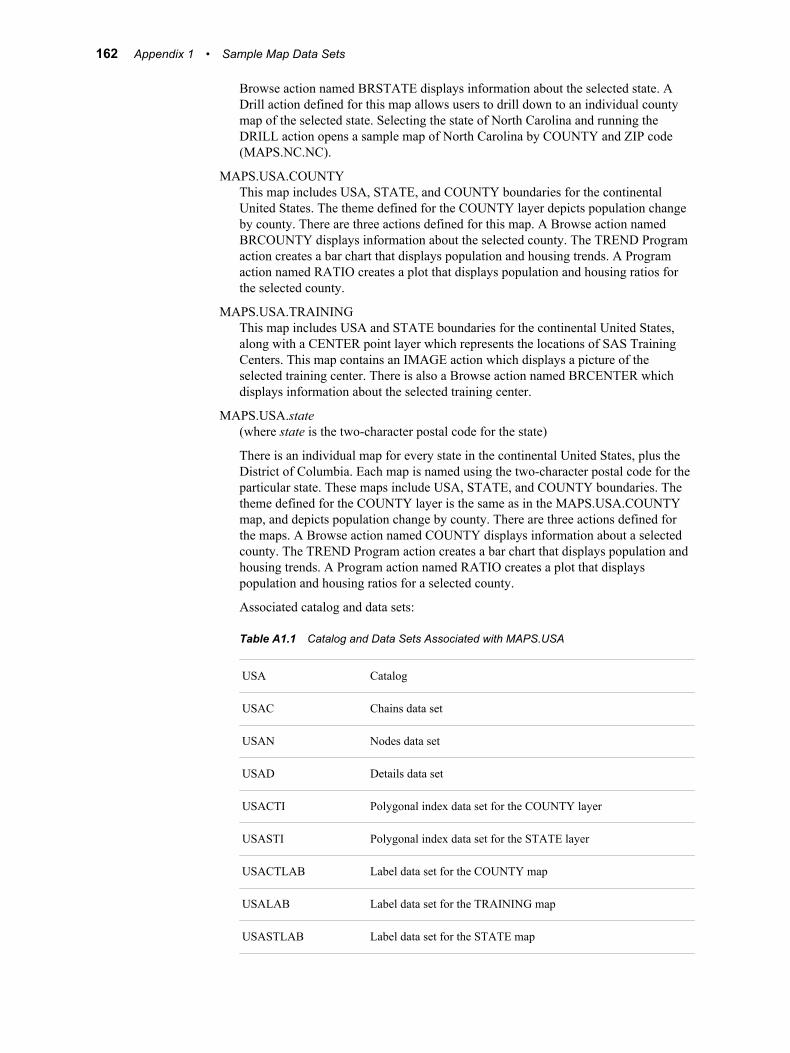
Browse action named BRSTATE displays information about the selected state. ADrill action defined for this map allows users to drill down to an individual countymap of the selected state. Selecting the state of North Carolina and running theDRILL action opens a sample map of North Carolina by COUNTY and ZIP code(MAPS.NC.NC).
MAPS.USA.COUNTYThis map includes USA, STATE, and COUNTY boundaries for the continentalUnited States. The theme defined for the COUNTY layer depicts population changeby county. There are three actions defined for this map. A Browse action namedBRCOUNTY displays information about the selected county. The TREND Programaction creates a bar chart that displays population and housing trends. A Programaction named RATIO creates a plot that displays population and housing ratios forthe selected county.
MAPS.USA.TRAININGThis map includes USA and STATE boundaries for the continental United States,along with a CENTER point layer which represents the locations of SAS TrainingCenters. This map contains an IMAGE action which displays a picture of theselected training center. There is also a Browse action named BRCENTER whichdisplays information about the selected training center.
MAPS.USA.state(where state is the two-character postal code for the state)
There is an individual map for every state in the continental United States, plus theDistrict of Columbia. Each map is named using the two-character postal code for theparticular state. These maps include USA, STATE, and COUNTY boundaries. Thetheme defined for the COUNTY layer is the same as in the MAPS.USA.COUNTYmap, and depicts population change by county. There are three actions defined forthe maps. A Browse action named COUNTY displays information about a selectedcounty. The TREND Program action creates a bar chart that displays population andhousing trends. A Program action named RATIO creates a plot that displayspopulation and housing ratios for a selected county.
Associated catalog and data sets:
Table A1.1 Catalog and Data Sets Associated with MAPS.USA
USA Catalog
USAC Chains data set
USAN Nodes data set
USAD Details data set
USACTI Polygonal index data set for the COUNTY layer
USASTI Polygonal index data set for the STATE layer
USACTLAB Label data set for the COUNTY map
USALAB Label data set for the TRAINING map
USASTLAB Label data set for the STATE map
162 Appendix 1 • Sample Map Data Sets
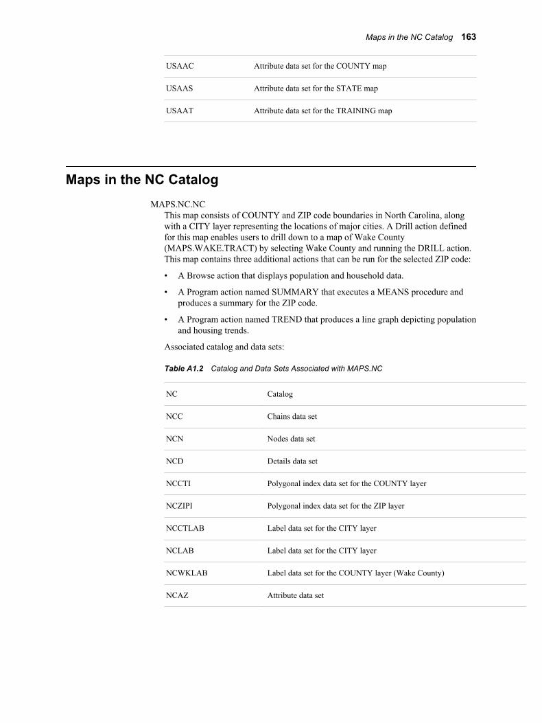
USAAC Attribute data set for the COUNTY map
USAAS Attribute data set for the STATE map
USAAT Attribute data set for the TRAINING map
Maps in the NC CatalogMAPS.NC.NC
This map consists of COUNTY and ZIP code boundaries in North Carolina, alongwith a CITY layer representing the locations of major cities. A Drill action definedfor this map enables users to drill down to a map of Wake County(MAPS.WAKE.TRACT) by selecting Wake County and running the DRILL action.This map contains three additional actions that can be run for the selected ZIP code:
• A Browse action that displays population and household data.
• A Program action named SUMMARY that executes a MEANS procedure andproduces a summary for the ZIP code.
• A Program action named TREND that produces a line graph depicting populationand housing trends.
Associated catalog and data sets:
Table A1.2 Catalog and Data Sets Associated with MAPS.NC
NC Catalog
NCC Chains data set
NCN Nodes data set
NCD Details data set
NCCTI Polygonal index data set for the COUNTY layer
NCZIPI Polygonal index data set for the ZIP layer
NCCTLAB Label data set for the CITY layer
NCLAB Label data set for the CITY layer
NCWKLAB Label data set for the COUNTY layer (Wake County)
NCAZ Attribute data set
Maps in the NC Catalog 163
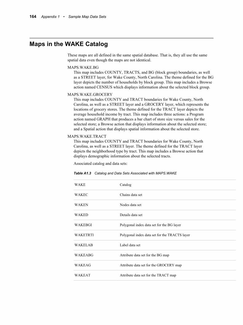
Maps in the WAKE CatalogThese maps are all defined in the same spatial database. That is, they all use the samespatial data even though the maps are not identical.
MAPS.WAKE.BGThis map includes COUNTY, TRACTS, and BG (block group) boundaries, as wellas a STREET layer, for Wake County, North Carolina. The theme defined for the BGlayer depicts the number of households by block group. This map includes a Browseaction named CENSUS which displays information about the selected block group.
MAPS.WAKE.GROCERYThis map includes COUNTY and TRACT boundaries for Wake County, NorthCarolina, as well as a STREET layer and a GROCERY layer, which represents thelocations of grocery stores. The theme defined for the TRACT layer depicts theaverage household income by tract. This map includes three actions: a Programaction named GRAPH that produces a bar chart of store size versus sales for theselected store; a Browse action that displays information about the selected store;and a Spatial action that displays spatial information about the selected store.
MAPS.WAKE.TRACTThis map includes COUNTY and TRACT boundaries for Wake County, NorthCarolina, as well as a STREET layer. The theme defined for the TRACT layerdepicts the neighborhood type by tract. This map includes a Browse action thatdisplays demographic information about the selected tracts.
Associated catalog and data sets:
Table A1.3 Catalog and Data Sets Associated with MAPS.WAKE
WAKE Catalog
WAKEC Chains data set
WAKEN Nodes data set
WAKED Details data set
WAKEBGI Polygonal index data set for the BG layer
WAKETRTI Polygonal index data set for the TRACTS layer
WAKELAB Label data set
WAKEABG Attribute data set for the BG map
WAKEAG Attribute data set for the GROCERY map
WAKEAT Attribute data set for the TRACT map
164 Appendix 1 • Sample Map Data Sets
Copying and Modifying SAS/GIS Maps in theMAPS Library
Because most SAS Software users do not have Write permission to the MAPS library,you will not be able to save any changes that you make to the SAS/GIS sample maps.You will see an error similar to the following in your SAS Log if you try to save anychanges made to these maps:
ERROR: Write access to member MAPS.NC.CATALOG is denied.
In order to save modifications to these maps, you must first copy the map and itsassociated data sets to a SAS library to which you have Write access. Use the Copyutility included with SAS/GIS to copy the maps.
For example, to copy the MAPS.NC.NC map and its associated data sets from theMAPS library to the SASUSER library, invoke SAS/GIS, select Edit ð Copy
Follow these steps:
1. Enter or browse and select MAPS.NC.NC for the Entry field.
2. Select Map as the entry Type.
3. In the Catalog Entry Destination field, enter the library and catalog to which youwill be copying the map. You must specify a currently allocated SAS library. If thespecified catalog does not already exist in the library, it will be created during thecopy process. In this example, enter SASUSER.NC.
4. In the Options box, select all options:
• Copy Source Entry
• Copy Dependent Entries
• Copy Dependent Data Sets
• Spatial Label Other
• Replace Like-Named Entries/Data Sets
• Blank out Path Name References
5. In the Data Set Destination field, enter the library to which the data sets associatedwith the map will be copied. In this case, enter SASUSER.
6. Click the Apply button to begin copying the map. When the copy is complete, youwill see a note in the message line similar to the following:
Number of entries, data sets copied: 9, 8
You will also see a list in the SAS Log window of all of the catalogs and data sets thatwere copied.
Now open the SASUSER.NC.NC map in the GIS Map window. You will now be able tomake any desired modifications to the map, and save those modifications to the copiedmap.
Copying and Modifying SAS/GIS Maps in the MAPS Library 165
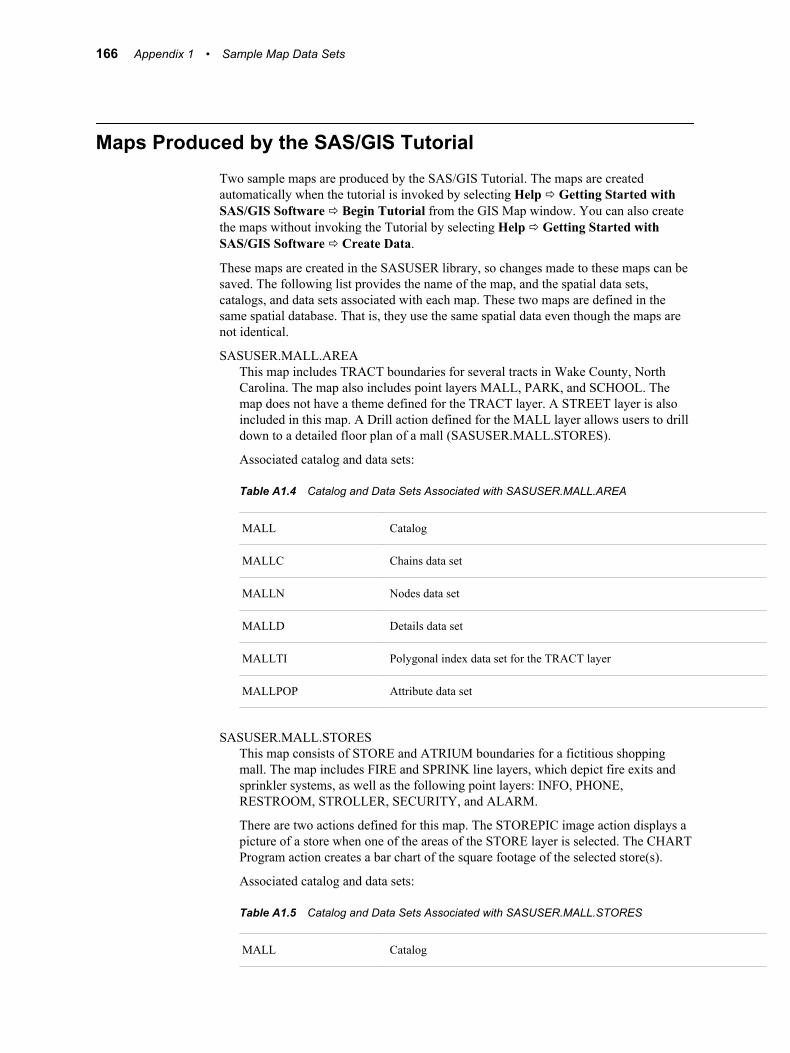
Maps Produced by the SAS/GIS TutorialTwo sample maps are produced by the SAS/GIS Tutorial. The maps are createdautomatically when the tutorial is invoked by selecting Help ð Getting Started withSAS/GIS Software ð Begin Tutorial from the GIS Map window. You can also createthe maps without invoking the Tutorial by selecting Help ð Getting Started withSAS/GIS Software ð Create Data.
These maps are created in the SASUSER library, so changes made to these maps can besaved. The following list provides the name of the map, and the spatial data sets,catalogs, and data sets associated with each map. These two maps are defined in thesame spatial database. That is, they use the same spatial data even though the maps arenot identical.
SASUSER.MALL.AREAThis map includes TRACT boundaries for several tracts in Wake County, NorthCarolina. The map also includes point layers MALL, PARK, and SCHOOL. Themap does not have a theme defined for the TRACT layer. A STREET layer is alsoincluded in this map. A Drill action defined for the MALL layer allows users to drilldown to a detailed floor plan of a mall (SASUSER.MALL.STORES).
Associated catalog and data sets:
Table A1.4 Catalog and Data Sets Associated with SASUSER.MALL.AREA
MALL Catalog
MALLC Chains data set
MALLN Nodes data set
MALLD Details data set
MALLTI Polygonal index data set for the TRACT layer
MALLPOP Attribute data set
SASUSER.MALL.STORESThis map consists of STORE and ATRIUM boundaries for a fictitious shoppingmall. The map includes FIRE and SPRINK line layers, which depict fire exits andsprinkler systems, as well as the following point layers: INFO, PHONE,RESTROOM, STROLLER, SECURITY, and ALARM.
There are two actions defined for this map. The STOREPIC image action displays apicture of a store when one of the areas of the STORE layer is selected. The CHARTProgram action creates a bar chart of the square footage of the selected store(s).
Associated catalog and data sets:
Table A1.5 Catalog and Data Sets Associated with SASUSER.MALL.STORES
MALL Catalog
166 Appendix 1 • Sample Map Data Sets

MALLC Chains data set
MALLN Nodes data set
MALLD Details data set
MALLSI Polygonal index data set for the STORE layer
MALLAI Polygonal index data set for the ATRIUM layer
MALLSTOR Attribute data set
Maps Produced by the SAS/GIS Tutorial 167

168 Appendix 1 • Sample Map Data Sets
Appendix 2
Spatial Database Details
The SAS/GIS Data Model . . . . . . . . . . . . . . . . . . . . . . . . . . . . . . . . . . . . . . . . . . . . . 169SAS/GIS Data Types . . . . . . . . . . . . . . . . . . . . . . . . . . . . . . . . . . . . . . . . . . . . . . . 169Spatial Data Features . . . . . . . . . . . . . . . . . . . . . . . . . . . . . . . . . . . . . . . . . . . . . . . 169SAS/GIS Topology . . . . . . . . . . . . . . . . . . . . . . . . . . . . . . . . . . . . . . . . . . . . . . . . . 170Rules for Topological Correctness . . . . . . . . . . . . . . . . . . . . . . . . . . . . . . . . . . . . . 170Attribute Data Features . . . . . . . . . . . . . . . . . . . . . . . . . . . . . . . . . . . . . . . . . . . . . . 172
SAS/GIS Spatial Database Structure . . . . . . . . . . . . . . . . . . . . . . . . . . . . . . . . . . . . 172Overview . . . . . . . . . . . . . . . . . . . . . . . . . . . . . . . . . . . . . . . . . . . . . . . . . . . . . . . . . 172Spatial Data Sets . . . . . . . . . . . . . . . . . . . . . . . . . . . . . . . . . . . . . . . . . . . . . . . . . . . 172Catalog Entries . . . . . . . . . . . . . . . . . . . . . . . . . . . . . . . . . . . . . . . . . . . . . . . . . . . . 176
Composites . . . . . . . . . . . . . . . . . . . . . . . . . . . . . . . . . . . . . . . . . . . . . . . . . . . . . . . . . . 180
The SAS/GIS Data Model
SAS/GIS Data TypesSAS/GIS software uses two basic types of data:
spatial datadescribes the location, shape, and interrelationships of map features.
attribute dataprovides information that relates to the map features.
Spatial Data FeaturesSAS/GIS software uses spatial data to represent the following three types of mapfeatures:
point featuresconsist of individual locations that are shown as symbols, representing real-worldlocations of special points of interest.
line featuresconsist of sequences of two or more coordinates that form zero-width shapes, eitherclosed or unclosed. Line features represent entities that either have no width, such aspolitical boundaries, or those that can be represented as having no width, such asstreets or water pipes.
169
area featuresconsist of sequences of three or more coordinates that form polygons (with single ormultiple boundaries and with or without holes.) Area features represent two-dimensional entities such as geographic areas (countries, states, and so on) or floorplans for buildings.
SAS/GIS TopologyTo represent point, line, and area features in a map, SAS/GIS software defines thefollowing topological features in the spatial data:
chainsare sequences of two or more points in the coordinate space. The end points (that is,the first and last points of the chain) are nodes. Each chain has a direction, from thefirst point toward the last point. The first point in the chain is the from-node and thelast point is the to-node. Relative to its direction, each chain has a left side and aright side.
Points between the from-node and the to-node are detail points, which serve to tracethe curvature of the feature that is represented by the chain. Detail points are notnodes.
nodesare points in the spatial data coordinate space that have connections to one or morechains.
areasare two-dimensional finite regions of the coordinate space. One or more chains,called boundary chains, separate two different areas. Chains that lie completelyinside an area are called internal chains and are bounded on the left and right sidesby the same area.
The spatial data coordinate space can be represented in any numeric units, even thosethat include arbitrary values. Coordinates that are stored as longitude and latitude valueshave a maximum usable precision of about one centimeter.
Representations of map features are implemented with one or more chains, as follows:
point featuresare implemented with one chain, one node (that is, the from-node and to-node for apoint feature are the same node), and no detail points.
line and area featuresare implemented with one or more chains and one or more nodes.
Rules for Topological Correctness
OverviewSAS/GIS spatial data must obey the following rules in order for the topology to becorrect. These rules are similar to the rules for TIGER files from the U.S. CensusBureau. For more information about these rules, see Gerard Boudriault's 1987 article,“Topology in the TIGER File” in AUTO-CARTA 8, Proceedings, pages 258-263,published by the American Society for Photogrammetry and Remote Sensing and theAmerican Congress on Surveying and Mapping.
170 Appendix 2 • Spatial Database Details
Topological CompletenessAll chains must have the following characteristics:
• They must be bounded by two nodes, the from-node and the to-node.
Note: In chains for point features, for single-chain closed-loop line features, or forarea boundaries, the from-node and the to-node are the same node, but both arestill included in the chain definition.
• They must be bounded by two areas, one on the left and one on the right.
These relationships must be complete, so the following two rules apply:
• The sides of all the chains incident to any given node must form a cycle. A cycleconsists of one or more chains that start or end at the same node.
• The end points of chains that bound an area must form one or more disjoint cycles.
For each unique area ID or unique set of area IDs, all the boundary chains that have theID value (either on the right or left, but not both) form one or more closed loops orcycles.
Topological-geometric ConsistencyThe collection of chains, nodes, and areas must have coordinates that make thecollection a disjoint partitioning of the coordinate space. The following four conditionsmust be true to avoid problems with displaying the spatial data:
• No two points in the combined set of nodes and detail points can share the samecoordinate.
• No two line segment interiors can share a common coordinate.
• No two areas can share a common coordinate.
Note: Graphically overlaid data can have overlapping polygons, chains, and nodesand have no topological interconnectivity
• Polygons that form the boundaries of holes inside areas must fall completely withinthe enclosing areas.
Note: Edge-matched data shares coordinates along common boundaries, but each chainshould have the proper polygonal ID values on the side that represents the outsideedge of their respective physical coverages as well as on the inside edge.
Problems Resulting from Topological ErrorsTopological errors in the spatial data cause the following types of problems:
• A polygonal index cannot be built for all the polygons for a particular area set.
• A successfully indexed polygon does not close because of the following problems:
• The chains for a node do not form a cycle, which is sometimes the result of left-and right-side values being swapped for one or more of the connected chains.
• A chain crosses another chain's interior coordinated space.
• Multiple features are selected when only one selection is desired because ofoverlapping features in a coordinate space.
• Select ð Like Connected processing fails to select apparently connected chains.
The SAS/GIS Data Model 171
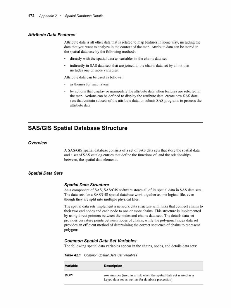
Attribute Data FeaturesAttribute data is all other data that is related to map features in some way, including thedata that you want to analyze in the context of the map. Attribute data can be stored inthe spatial database by the following methods:
• directly with the spatial data as variables in the chains data set
• indirectly in SAS data sets that are joined to the chains data set by a link thatincludes one or more variables.
Attribute data can be used as follows:
• as themes for map layers.
• by actions that display or manipulate the attribute data when features are selected inthe map. Actions can be defined to display the attribute data, create new SAS datasets that contain subsets of the attribute data, or submit SAS programs to process theattribute data.
SAS/GIS Spatial Database Structure
OverviewA SAS/GIS spatial database consists of a set of SAS data sets that store the spatial dataand a set of SAS catalog entries that define the functions of, and the relationshipsbetween, the spatial data elements.
Spatial Data Sets
Spatial Data StructureAs a component of SAS, SAS/GIS software stores all of its spatial data in SAS data sets.The data sets for a SAS/GIS spatial database work together as one logical file, eventhough they are split into multiple physical files.
The spatial data sets implement a network data structure with links that connect chains totheir two end nodes and each node to one or more chains. This structure is implementedby using direct pointers between the nodes and chains data sets. The details data setprovides curvature points between nodes of chains, while the polygonal index data setprovides an efficient method of determining the correct sequence of chains to representpolygons.
Common Spatial Data Set VariablesThe following spatial data variables appear in the chains, nodes, and details data sets:
Table A2.1 Common Spatial Data Set Variables
Variable Description
ROW row number (used as a link when the spatial data set is used as akeyed data set as well as for database protection)
172 Appendix 2 • Spatial Database Details
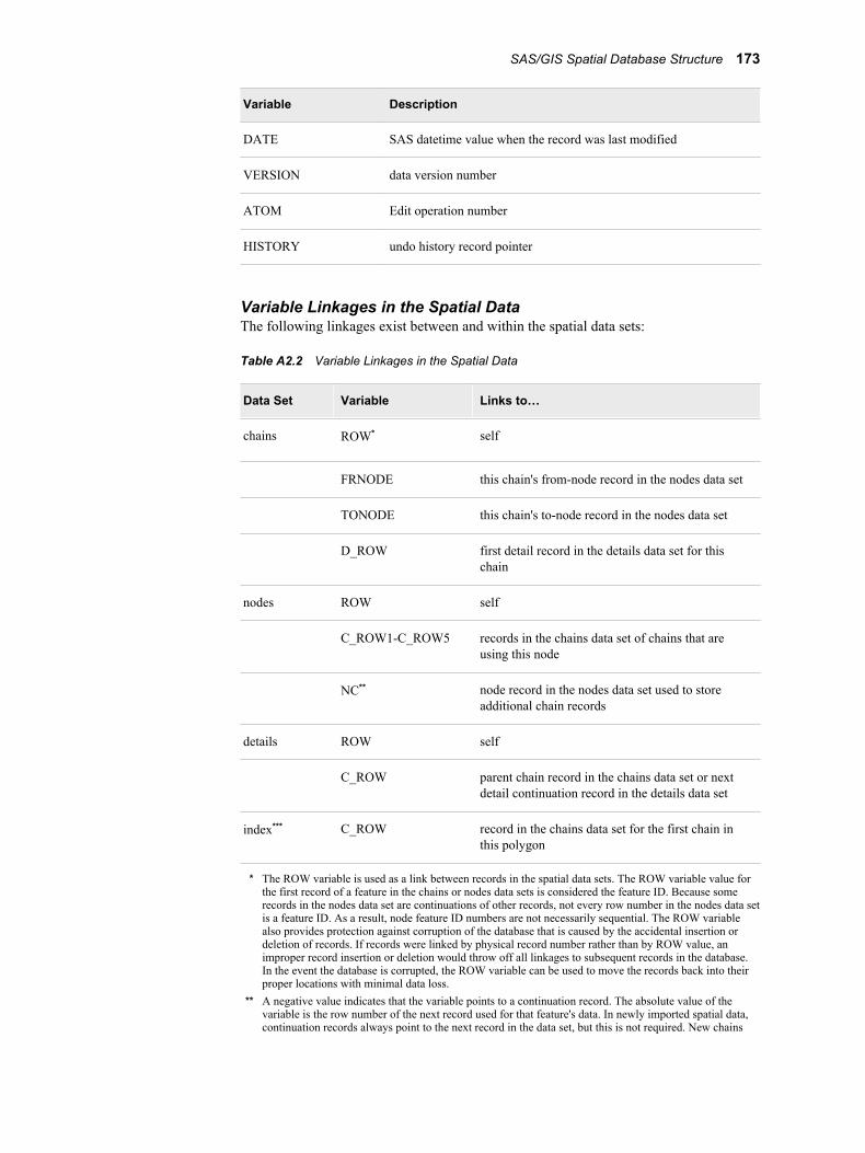
Variable Description
DATE SAS datetime value when the record was last modified
VERSION data version number
ATOM Edit operation number
HISTORY undo history record pointer
Variable Linkages in the Spatial DataThe following linkages exist between and within the spatial data sets:
Table A2.2 Variable Linkages in the Spatial Data
Data Set Variable Links to…
chains ROW* self
FRNODE this chain's from-node record in the nodes data set
TONODE this chain's to-node record in the nodes data set
D_ROW first detail record in the details data set for thischain
nodes ROW self
C_ROW1-C_ROW5 records in the chains data set of chains that areusing this node
NC** node record in the nodes data set used to storeadditional chain records
details ROW self
C_ROW parent chain record in the chains data set or nextdetail continuation record in the details data set
index*** C_ROW record in the chains data set for the first chain inthis polygon
* The ROW variable is used as a link between records in the spatial data sets. The ROW variable value forthe first record of a feature in the chains or nodes data sets is considered the feature ID. Because somerecords in the nodes data set are continuations of other records, not every row number in the nodes data setis a feature ID. As a result, node feature ID numbers are not necessarily sequential. The ROW variablealso provides protection against corruption of the database that is caused by the accidental insertion ordeletion of records. If records were linked by physical record number rather than by ROW value, animproper record insertion or deletion would throw off all linkages to subsequent records in the database.In the event the database is corrupted, the ROW variable can be used to move the records back into theirproper locations with minimal data loss.
** A negative value indicates that the variable points to a continuation record. The absolute value of thevariable is the row number of the next record used for that feature's data. In newly imported spatial data,continuation records always point to the next record in the data set, but this is not required. New chains
SAS/GIS Spatial Database Structure 173
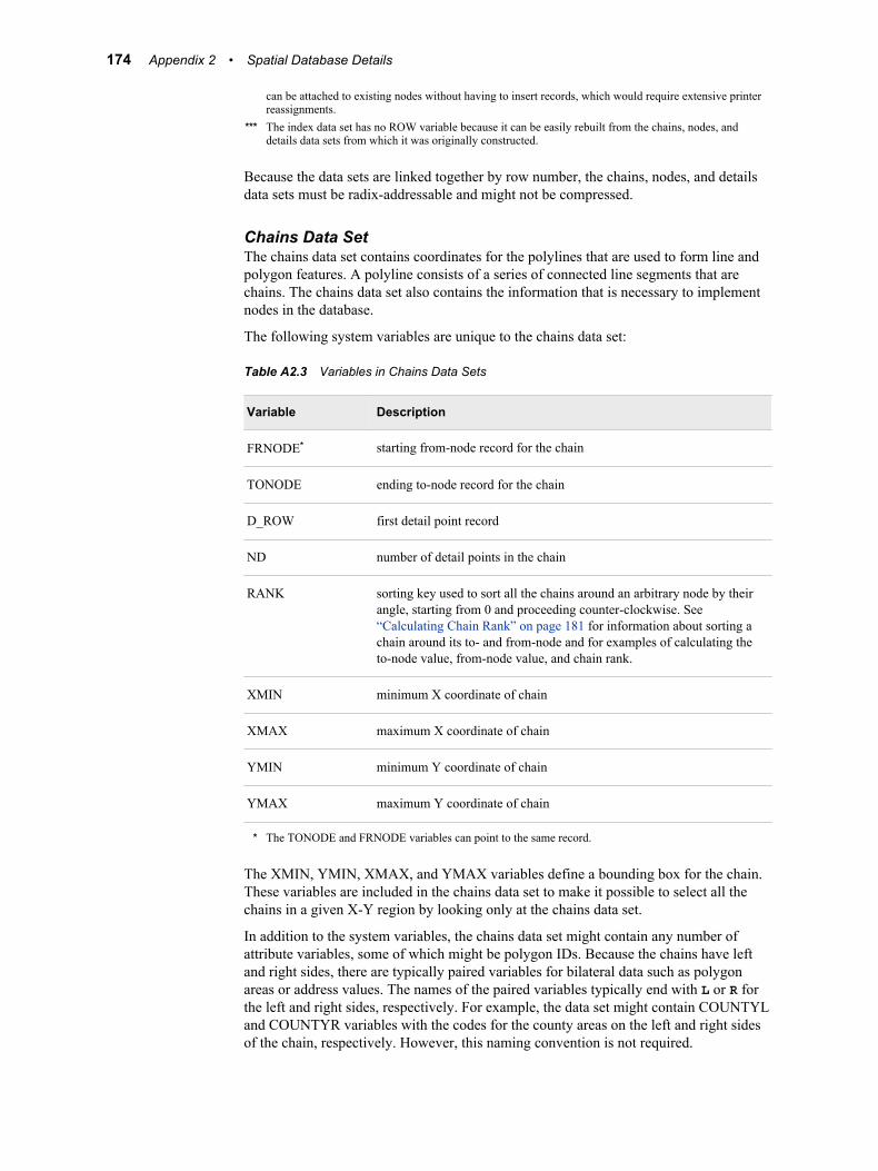
can be attached to existing nodes without having to insert records, which would require extensive printerreassignments.
*** The index data set has no ROW variable because it can be easily rebuilt from the chains, nodes, anddetails data sets from which it was originally constructed.
Because the data sets are linked together by row number, the chains, nodes, and detailsdata sets must be radix-addressable and might not be compressed.
Chains Data SetThe chains data set contains coordinates for the polylines that are used to form line andpolygon features. A polyline consists of a series of connected line segments that arechains. The chains data set also contains the information that is necessary to implementnodes in the database.
The following system variables are unique to the chains data set:
Table A2.3 Variables in Chains Data Sets
Variable Description
FRNODE* starting from-node record for the chain
TONODE ending to-node record for the chain
D_ROW first detail point record
ND number of detail points in the chain
RANK sorting key used to sort all the chains around an arbitrary node by theirangle, starting from 0 and proceeding counter-clockwise. See“Calculating Chain Rank” on page 181 for information about sorting achain around its to- and from-node and for examples of calculating theto-node value, from-node value, and chain rank.
XMIN minimum X coordinate of chain
XMAX maximum X coordinate of chain
YMIN minimum Y coordinate of chain
YMAX maximum Y coordinate of chain
* The TONODE and FRNODE variables can point to the same record.
The XMIN, YMIN, XMAX, and YMAX variables define a bounding box for the chain.These variables are included in the chains data set to make it possible to select all thechains in a given X-Y region by looking only at the chains data set.
In addition to the system variables, the chains data set might contain any number ofattribute variables, some of which might be polygon IDs. Because the chains have leftand right sides, there are typically paired variables for bilateral data such as polygonareas or address values. The names of the paired variables typically end with L or R forthe left and right sides, respectively. For example, the data set might contain COUNTYLand COUNTYR variables with the codes for the county areas on the left and right sidesof the chain, respectively. However, this naming convention is not required.
174 Appendix 2 • Spatial Database Details
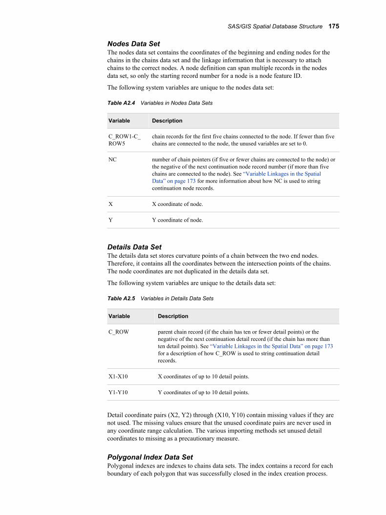
Nodes Data SetThe nodes data set contains the coordinates of the beginning and ending nodes for thechains in the chains data set and the linkage information that is necessary to attachchains to the correct nodes. A node definition can span multiple records in the nodesdata set, so only the starting record number for a node is a node feature ID.
The following system variables are unique to the nodes data set:
Table A2.4 Variables in Nodes Data Sets
Variable Description
C_ROW1-C_ROW5
chain records for the first five chains connected to the node. If fewer than fivechains are connected to the node, the unused variables are set to 0.
NC number of chain pointers (if five or fewer chains are connected to the node) orthe negative of the next continuation node record number (if more than fivechains are connected to the node). See “Variable Linkages in the SpatialData” on page 173 for more information about how NC is used to stringcontinuation node records.
X X coordinate of node.
Y Y coordinate of node.
Details Data SetThe details data set stores curvature points of a chain between the two end nodes.Therefore, it contains all the coordinates between the intersection points of the chains.The node coordinates are not duplicated in the details data set.
The following system variables are unique to the details data set:
Table A2.5 Variables in Details Data Sets
Variable Description
C_ROW parent chain record (if the chain has ten or fewer detail points) or thenegative of the next continuation detail record (if the chain has more thanten detail points). See “Variable Linkages in the Spatial Data” on page 173for a description of how C_ROW is used to string continuation detailrecords.
X1-X10 X coordinates of up to 10 detail points.
Y1-Y10 Y coordinates of up to 10 detail points.
Detail coordinate pairs (X2, Y2) through (X10, Y10) contain missing values if they arenot used. The missing values ensure that the unused coordinate pairs are never used inany coordinate range calculation. The various importing methods set unused detailcoordinates to missing as a precautionary measure.
Polygonal Index Data SetPolygonal indexes are indexes to chains data sets. The index contains a record for eachboundary of each polygon that was successfully closed in the index creation process.
SAS/GIS Spatial Database Structure 175
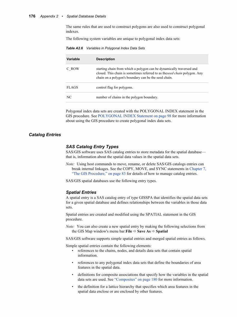
The same rules that are used to construct polygons are also used to construct polygonalindexes.
The following system variables are unique to polygonal index data sets:
Table A2.6 Variables in Polygonal Index Data Sets
Variable Description
C_ROW starting chain from which a polygon can be dynamically traversed andclosed. This chain is sometimes referred to as theseed chain polygon. Anychain on a polygon's boundary can be the seed chain.
FLAGS control flag for polygons.
NC number of chains in the polygon boundary.
Polygonal index data sets are created with the POLYGONAL INDEX statement in theGIS procedure. See POLYGONAL INDEX Statement on page 98 for more informationabout using the GIS procedure to create polygonal index data sets.
Catalog Entries
SAS Catalog Entry TypesSAS/GIS software uses SAS catalog entries to store metadata for the spatial database—that is, information about the spatial data values in the spatial data sets.
Note: Using host commands to move, rename, or delete SAS/GIS catalogs entries canbreak internal linkages. See the COPY, MOVE, and SYNC statements in Chapter 7,“The GIS Procedure,” on page 83 for details of how to manage catalog entries.
SAS/GIS spatial databases use the following entry types.
Spatial EntriesA spatial entry is a SAS catalog entry of type GISSPA that identifies the spatial data setsfor a given spatial database and defines relationships between the variables in those datasets.
Spatial entries are created and modified using the SPATIAL statement in the GISprocedure.
Note: You can also create a new spatial entry by making the following selections fromthe GIS Map window's menu bar:File ð Save As ð Spatial
SAS/GIS software supports simple spatial entries and merged spatial entries as follows.
Simple spatial entries contain the following elements:• references to the chains, nodes, and details data sets that contain spatial
information.
• references to any polygonal index data sets that define the boundaries of areafeatures in the spatial data.
• definitions for composite associations that specify how the variables in the spatialdata sets are used. See “Composites” on page 180 for more information.
• the definition for a lattice hierarchy that specifies which area features in thespatial data enclose or are enclosed by other features.
176 Appendix 2 • Spatial Database Details
• the parameters for the projection system that is used to interpret the spatialinformation that is stored in the spatial data sets.
• the accumulated bounding extents of the spatial data coordinates of its underlyingchild spatial data sets, consisting of the minimum and maximum X and Ycoordinate values and the ranges of X and Y values.
Merged spatial entries have the following characteristics:• consist of multiple SAS/GIS spatial databases that are linked together
hierarchically in a tree structure.
• contain logical references to two or more child spatial entries. A child spatialentry is a dependent spatial entry beneath the merged spatial entry in thehierarchy.
• contain specifications of how the entries were merged (by overlapping oredgematching).
• do not have their own spatial data sets.
• reference the spatial data sets that belong to the child spatial entries beneath themon the hierarchy.
• do not have references to any polygonal index data sets that define theboundaries of area features in the spatial data.
• do not have definitions for composites that specify how the variables in thespatial data sets are used. See “Composites” on page 180 for more informationabout composites.
• do not have the definition for a lattice hierarchy that specifies which area featuresin the spatial data enclose or are enclosed by other features.
• do not have parameters for the projection system that is used to interpret thespatial information that is stored in the spatial data sets.
• contain the accumulated bounding extents of the spatial data coordinates of theirunderlying child spatial entries, consisting of the minimum and maximum X andY coordinate values and the ranges of X and Y values.
Merged spatial entries can help you to manage your spatial data requirements. Forexample, you might have two spatial databases that contain the county boundaries ofadjoining states. You can build a merged spatial entry that references both states andthen you can view a single map containing both states' counties. Otherwise, youwould have to import a new map that contains the two states' counties. This new mapwould double your spatial data storage requirements.
The following additional statements in the GIS procedure update the information in thespatial entry:
COMPOSITE statementcreates or modifies composites that define the relation and function of variables inthe spatial data sets. See COMPOSITE Statement on page 93 for details about usingthe GIS procedure to create or modify composites.
POLYGONAL INDEX statementupdates the list of available index names that are stored in the spatial entry. SeePOLYGONAL INDEX Statement on page 98 for details about using the GISprocedure to create or modify polygonal indexes.
LATTICE statementupdates the lattice hierarchy that is stored in the spatial entry. See LATTICEStatement on page 102 for details about using the GIS procedure to define latticehierarchies.
SAS/GIS Spatial Database Structure 177

You can view a formatted report of the contents of a spatial entry by submitting aSPATIAL CONTENTS statement in the GIS procedure.
See SPATIAL Statement on page 88 for more information about using the GISprocedure to create, modify, or view the contents of spatial entries.
Coverage EntriesA coverage entry is a SAS catalog entry of type GISCOVER that defines the subset, orcoverage, of the spatial data that is available to a map. SAS/GIS maps refer to coveragesrather than directly to the spatial data.
A coverage entry contains the following elements:
• a reference to the root spatial entry.
• a WHERE expression that describes the logical subset of the spatial data that isavailable for display in a map. (The expression WHERE=1 can be used to define acoverage that includes all the data that is in the spatial database.)
The WHERE expression binds the coverage entry to the spatial data sets that itsubsets. The WHERE expression is checked for compatibility with the spatial datawhen the coverage entry is created and also whenever a map that uses the coverageentry is opened.
• the maximum and minimum X and Y coordinates in the portion of the spatial datathat meets the WHERE expression criteria for the coverage.
These maximum and minimum coordinates are evaluated when the coverage iscreated. The GIS procedure's COVERAGE CREATE statement reads the matchingchains and determines the extents from the chains' XMIN, YMIN, XMAX, andYMAX variables. If you make changes to the chains, nodes, and details data sets thataffect the coverage extents, you should use the COVERAGE UPDATE statement toupdate the bounding extent values.
Multiple coverage entries can refer to the same spatial entry to create different subsets ofthe spatial data for different maps. For example, you could define a series of coveragesto subset a county into multiple sales regions according to the block groups that arecontained in each of the regions. The spatial data for the county would still be in a singlespatial database that is represented by the chains, nodes, and details data sets and by thecontrolling spatial entry.
Coverage entries are created and modified using the COVERAGE statement in the GISprocedure. You can view a formatted report of the contents of a coverage entry bysubmitting a COVERAGE CONTENTS statement in the GIS procedure. (The contentsreport for a coverage entry also includes all the contents information for the root spatialentry as well.)
See COVERAGE Statement on page 104 for more information about using the GISprocedure to create, modify, or view the contents of coverage entries.
Layer EntriesA layer entry is a SAS catalog entry of type GISLAYER that defines the set of featuresthat compose a layer in the map. A layer entry contains the following elements:
• a WHERE expression that describes the common characteristic of features in thelayer.
The WHERE expression binds the layer entry to the spatial data even though it isstored in a separate entry. The layer is not bound to a specific spatial entry, just tothose entries representing the same type of data. Therefore, a layer that is created foruse with data that is imported from a TIGER file can be used with data that is
178 Appendix 2 • Spatial Database Details
imported from any TIGER file. However, not all file types can take advantage of thisbehavior. The WHERE expression is checked for compatibility with spatial datawhen the layer entry is created and also whenever a map that uses the layer entry isopened.
Note: When you define area layers, you can specify a composite as an alternative tospecifying an explicit WHERE expression. However, the layer entry stores theWHERE expression that is implied by the composite. For example, if you specifySTATE as the defining composite for a layer, and the STATE compositespecifies the variable association VAR=(LEFT=STATEL,RIGHT=STATER),then the implied WHERE expression that is stored in the layer entry is WHERESTATEL NE STATER.
• option settings for the layer such as the layer type (point, line, or area), whether thelayer is static or thematic, whether it is initially displayed or hidden, whether detailpoints are drawn for the layer, and the scales at which the layer is automaticallyturned on or off.
• the graphical attributes that are necessary to draw the layer if it is a static layer.
• the attribute links, theme range breaks, and graphical attributes if the layer containsthemes.
See LAYER Statement on page 107 for more information about using the GIS procedureto create, modify, or view the contents of layer entries.
Map EntriesA map entry is a SAS catalog entry of type GISMAP. Map entries are the controllingentries for SAS/GIS maps because they tie together all the information that is needed todisplay a map. A map entry contains the following elements:
• a reference to the coverage entry that defines the subset of the spatial data that isavailable to the map. Note that the map entry refers to a particular coverage of thespatial data rather than directly to the spatial entry.
• references to the layer entries for all layers that are included in the map.
• references to any attribute data sets that are associated with the map, along withdefinitions of how the attribute data sets are linked to the spatial data.
• a reference to the SAS data set that contains labels for map features.
• definitions for the actions that can be performed when map features are selected.
• definitions for map legends.
• parameters for the projection system that is used to project spatial data coordinatesfor display.
• option settings for the map, including the following:
• the units and mode for the map scale
• whether coordinate, distance, and attribute feedback are displayed
• whether detail points are read
• whether the tool palette is active.
Map entries are created using the MAP CREATE statement in the GIS procedure.However, much of the information that is stored in the map entry is specifiedinteractively in the GIS Map window.
SAS/GIS Spatial Database Structure 179
You can view a formatted report of the contents of a map entry by submitting a MAPCONTENTS statement in the GIS procedure. (The contents report for a map entryincludes all the contents information for the spatial, coverage, and layer entries as well.)
See MAP Statement on page 133 for details about the items that can be specified withthe GIS procedure. See Chapter 10, “SAS/GIS Windows” in SAS/GIS Software: Usageand Reference, Version 6 for details about the items that can be specified interactively inthe GIS Map window.
CompositesFor most operations that involve the spatial database, you refer to composites of thespatial data variables rather than directly to the variables in the spatial data sets. Acomposite consists of the following elements:
• a variable association that identifies which variable or variables in the spatialdatabase comprise the association. The variable association can specify a singlevariable, a pair of variables that define a bilateral (left-right) association, or two pairsof variables that define the start and end of a directional (from-to) bilateralassociation.
• a class attribute that identifies the role of the composite in the spatial database.
For example, if the chains data set has a variable that is named FEANAME that containsfeature names, then you can create a composite for the FEANAME variable that assignsthe class attribute NAME to indicate that the composite represents feature names. If thechains data set has COUNTYL and COUNTYR variables that contain the codes for thecounties on the left and right sides of the chains, then you can create a composite that isnamed COUNTY. The composite identifies the bilateral relationship between these twovariables and assigns the class attribute AREA to indicate that the composite definescounty areas in the spatial data.
Composites are created and modified using the COMPOSITE statement in the GISprocedure. Composite definitions are stored in the spatial entry.
See COMPOSITE Statement on page 93 for more information about using the GISprocedure to create or modify composites.
180 Appendix 2 • Spatial Database Details
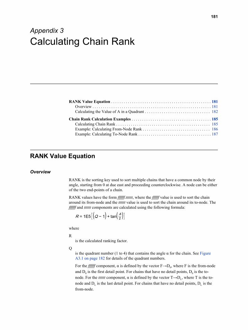
Appendix 3
Calculating Chain Rank
RANK Value Equation . . . . . . . . . . . . . . . . . . . . . . . . . . . . . . . . . . . . . . . . . . . . . . . . 181Overview . . . . . . . . . . . . . . . . . . . . . . . . . . . . . . . . . . . . . . . . . . . . . . . . . . . . . . . . . 181Calculating the Value of A in a Quadrant . . . . . . . . . . . . . . . . . . . . . . . . . . . . . . . 182
Chain Rank Calculation Examples . . . . . . . . . . . . . . . . . . . . . . . . . . . . . . . . . . . . . . 185Calculating Chain Rank . . . . . . . . . . . . . . . . . . . . . . . . . . . . . . . . . . . . . . . . . . . . . 185Example: Calculating From-Node Rank . . . . . . . . . . . . . . . . . . . . . . . . . . . . . . . . 186Example: Calculating To-Node Rank . . . . . . . . . . . . . . . . . . . . . . . . . . . . . . . . . . . 187
RANK Value Equation
OverviewRANK is the sorting key used to sort multiple chains that have a common node by theirangle, starting from 0 at due east and proceeding counterclockwise. A node can be eitherof the two end-points of a chain.
RANK values have the form ffffff.tttttt, where the ffffff value is used to sort the chainaround its from-node and the tttttt value is used to sort the chain around its to-node. Theffffff and tttttt components are calculated using the following formula:
R = 1E5 (Q − 1) + tan( A2 )where
Ris the calculated ranking factor.
Qis the quadrant number (1 to 4) that contains the angle α for the chain. See FigureA3.1 on page 182 for details of the quadrant numbers.
For the ffffff component, α is defined by the vector F→D0, where F is the from-nodeand D0 is the first detail point. For chains that have no detail points, D0 is the to-node. For the tttttt component, α is defined by the vector T→DL, where T is the to-node and DL is the last detail point. For chains that have no detail points, DL is thefrom-node.
181
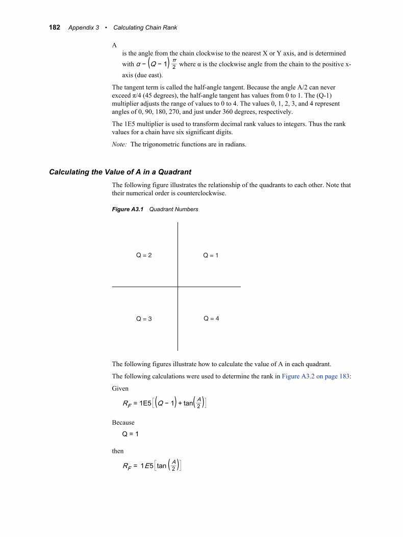
Ais the angle from the chain clockwise to the nearest X or Y axis, and is determinedwith α − (Q − 1) π2 where α is the clockwise angle from the chain to the positive x-axis (due east).
The tangent term is called the half-angle tangent. Because the angle A/2 can neverexceed π/4 (45 degrees), the half-angle tangent has values from 0 to 1. The (Q-1)multiplier adjusts the range of values to 0 to 4. The values 0, 1, 2, 3, and 4 representangles of 0, 90, 180, 270, and just under 360 degrees, respectively.
The 1E5 multiplier is used to transform decimal rank values to integers. Thus the rankvalues for a chain have six significant digits.
Note: The trigonometric functions are in radians.
Calculating the Value of A in a QuadrantThe following figure illustrates the relationship of the quadrants to each other. Note thattheir numerical order is counterclockwise.
Figure A3.1 Quadrant Numbers
Q = 3 Q = 4
Q = 2 Q = 1
The following figures illustrate how to calculate the value of A in each quadrant.
The following calculations were used to determine the rank in Figure A3.2 on page 183:
Given
RF = 1E5 (Q − 1) + tan( A2 )Because
Q = 1
then
RF = 1E5 tan ( A2 )
182 Appendix 3 • Calculating Chain Rank
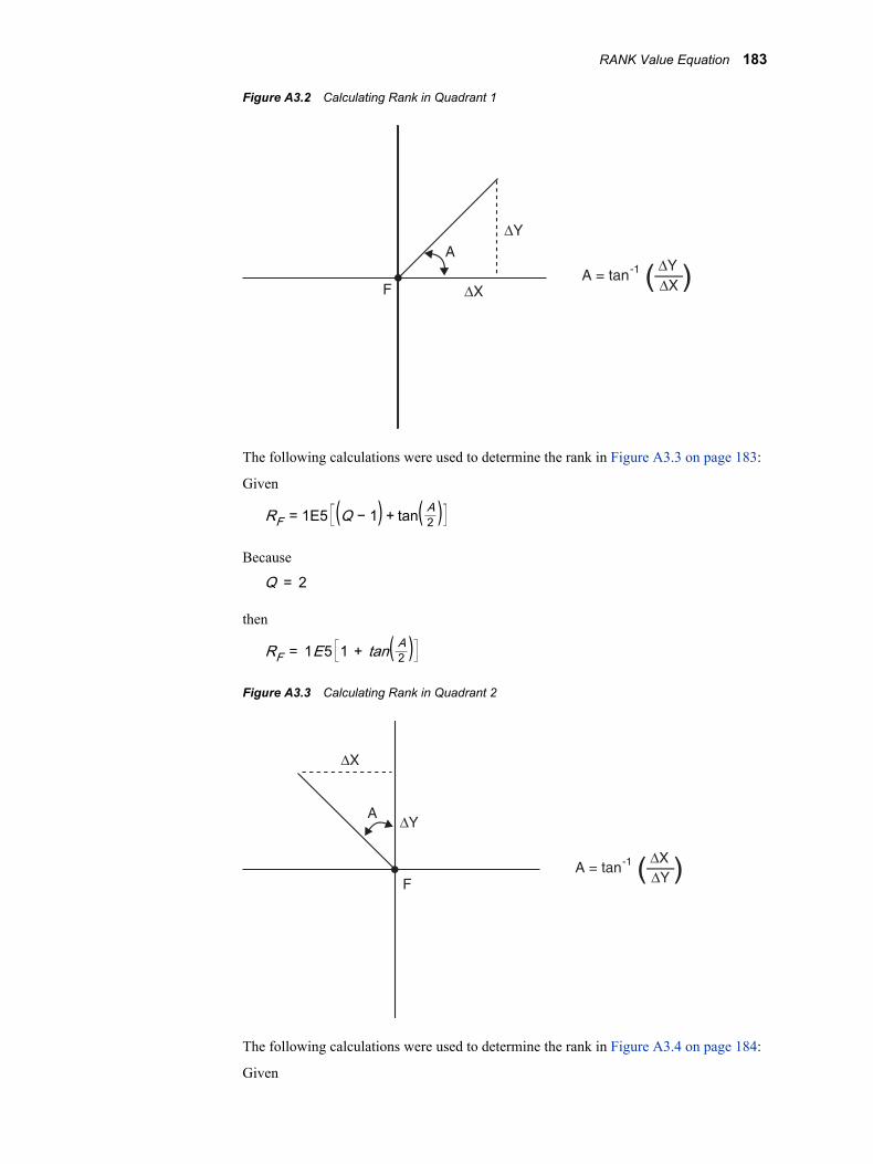
Figure A3.2 Calculating Rank in Quadrant 1
A = tan -1 ∆Y
∆X( )∆X
A
∆Y
F
The following calculations were used to determine the rank in Figure A3.3 on page 183:
Given
RF = 1E5 (Q − 1) + tan( A2 )Because
Q = 2
then
RF = 1E5 1 + tan( A2 )Figure A3.3 Calculating Rank in Quadrant 2
A = tan -1 ∆X
∆Y( )
∆X
A∆Y
F
The following calculations were used to determine the rank in Figure A3.4 on page 184:
Given
RANK Value Equation 183
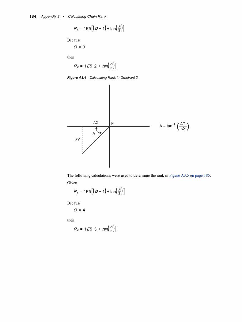
RF = 1E5 (Q − 1) + tan( A2 )Because
Q = 3
then
RF = 1E5 2 + tan( A2 )Figure A3.4 Calculating Rank in Quadrant 3
A = tan -1 ∆Y
∆X( )∆X
A
∆Y
F
The following calculations were used to determine the rank in Figure A3.5 on page 185:
Given
RF = 1E5 (Q − 1) + tan( A2 )Because
Q = 4
then
RF = 1E5 3 + tan( A2 )
184 Appendix 3 • Calculating Chain Rank
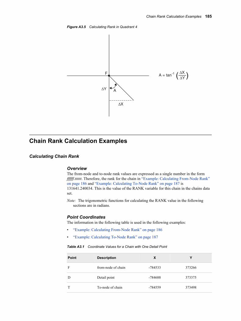
Figure A3.5 Calculating Rank in Quadrant 4
∆X
A = tan -1 ∆X
∆Y( )
A∆Y
F
Chain Rank Calculation Examples
Calculating Chain Rank
OverviewThe from-node and to-node rank values are expressed as a single number in the formffffff.tttttt. Therefore, the rank for the chain in “Example: Calculating From-Node Rank”on page 186 and “Example: Calculating To-Node Rank” on page 187 is131641.240034. This is the value of the RANK variable for this chain in the chains dataset.
Note: The trigonometric functions for calculating the RANK value in the followingsections are in radians.
Point CoordinatesThe information in the following table is used in the following examples:
• “Example: Calculating From-Node Rank” on page 186
• “Example: Calculating To-Node Rank” on page 187
Table A3.1 Coordinate Values for a Chain with One Detail Point
Point Description X Y
F from-node of chain -784533 373266
D Detail point -784688 373375
T To-node of chain -784559 373498
Chain Rank Calculation Examples 185
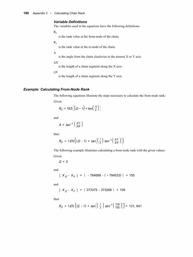
Variable DefinitionsThe variables used in the equations have the following definitions:
RF
is the rank value at the from-node of the chain.
RT
is the rank value at the to-node of the chain.
Ais the angle from the chain clockwise to the nearest X or Y axis.
ΔXis the length of a chain segment along the X axis.
ΔYis the length of a chain segment along the Y axis.
Example: Calculating From-Node RankThe following equations illustrate the steps necessary to calculate the from-node rank:
Given
RF = 1E5 (Q − 1) + tan( A2 )
and
A = tan -1 ( ΔYΔX )then
RF = 1E5 { (Q - 1) + tan ( 12 ) tan -1 ( ΔYΔX ) }The following example illustrates calculating a from-node rank with the given values:
Given
Q = 2
and
| X D - XF | = | - 784688 - ( − 784533) | = 155
and
| X D - XF | = | 373375 - 373266 | = 109
then
RF = 1E5 { (2 - 1) + tan ( 12 ) tan -1 ( 109155 ) } = 131, 641
186 Appendix 3 • Calculating Chain Rank
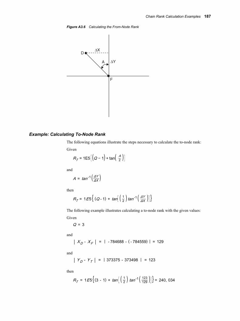
Figure A3.6 Calculating the From-Node Rank
∆Y
D
F
∆X
A
Example: Calculating To-Node RankThe following equations illustrate the steps necessary to calculate the to-node rank:
Given
RT = 1E5 (Q − 1) + tan( A2 )
and
A = tan -1 ( ΔYΔX )then
RT = 1E5 { (Q - 1) + tan ( 12 ) tan -1 ( ΔYΔX ) }The following example illustrates calculating a to-node rank with the given values:
Given
Q = 3
and
| XD - XF | = | - 784688 - ( - 784559) | = 129
and
| YD - YT | = | 373375 - 373498 | = 123
then
RT = 1E5 { (3 - 1) + tan ( 12 ) tan -1 ( 123129 ) } = 240, 034
Chain Rank Calculation Examples 187
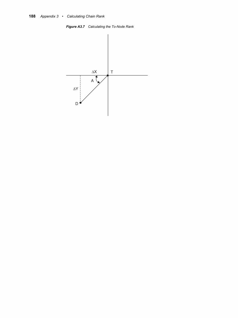
Figure A3.7 Calculating the To-Node Rank
∆X
A
∆Y
D
T
188 Appendix 3 • Calculating Chain Rank
Glossary
ArcInfoa geographic information system software product that is developed and supportedby ESRI.
area layera layer that contains the regions, such as census tracts or ZIP code zones, that arepart of a map.
attribute datavalues that are associated with features on a map. Attribute data is linked to mapfeatures by key variables. Attribute data can include information such as householdincomes, population, sales revenue, ages, and so on.
catalogSee SAS catalog.
chaina sequence of two or more points in the coordinate space. The end points (that is, thefirst and last points of the chain) are called nodes.
coveragea subset of the spatial data that is available to a map. For example, a coverage mightinclude the spatial data for a region of a map that is contained in a spatial database.
coverage entrya SAS catalog entry of type GISCOVER that defines the subset, or coverage, of thespatial data that is available to a map.
data setSee SAS data set.
data typean attribute of every column in a table or database. The data type tells the operatingsystem how much physical storage to set aside for the column and specifies whattype of data the column will contain. It is similar to the type attribute of SASvariables.
data valuea unit of character, numeric, or alphanumeric information. This unit is stored as oneitem in a data record, such as a person’s height being stored as one variable (namely,a column or vertical component) in an observation (row).
189
database management systema software application that enables you to create and manipulate data that is stored inthe form of databases. Short form: DBMS.
DBMSSee database management system.
detail pointan intermediate point that delineates the interior segment of a line. Detail points arethose points on a line between the from-node and the to-node.
DLGDigital Line Graph. A data exchange format for planimetric data. DLG wasdeveloped by the United States Geological Survey (USGS).
DXFa data exchange format that is widely used in computer-aided design (CAD)applications.
Dynamapspatial (map) data that is developed and supported by Tele Atlas NV.
external filea file that is created and maintained by a host operating system or by anothervendor's software application. An external file can read both data and stored SASstatements.
featurea man-made or natural physical object such as a river, utility line, school, street, orhighway; or an intangible boundary or area such as a sales territory, a census tract, acounty boundary, or a state boundary.
feedback areaan area in the GIS Map window that displays information about the map scale, aswell as about location coordinates, distance values, and attribute values.
file referenceSee fileref.
filerefa name that is temporarily assigned to an external file or to an aggregate storagelocation such as a directory or a folder. The fileref identifies the file or the storagelocation to SAS.
from-nodethe starting coordinates of a line segment on a SAS/GIS map.
generic import filea file that contains spatial data that you can import by writing a SAS DATA step toconvert the data to a SAS/GIS generic form. Once the data is in this generic form,SAS/GIS software can finish the import process.
geocodingthe process of assigning geographic coordinates (often expressed as latitude andlongitude) to other geographic data such as street addresses, or postal codes.
190 Glossary

geographic information systema software application for organizing and analyzing data that can be referencedspatially - that is, data that can be associated with physical locations. Many types ofdata, such as data from marketing surveys and epidemiological studies, have a spatialaspect. Short form: GIS.
GISSee geographic information system.
key variablean industry-standard file format for compressed images. Saving an image in JPEGformat typically provides 10:1 compression with little perceptible loss in imagequality. Short form: JPEG.
label data seta data set that defines the attributes (location, color, size, and so on) of labels thatwill be displayed on a map.
layera group of features that have the same attribute. For example, all of the lines that arestreets, all of the points that are houses, and all of the areas that are census tracts arelayers.
layer definitiona WHERE clause that is applied to spatial data in order to specify which features willbe displayed in a layer.
layer entrya SAS catalog entry of type GISLAYER that includes the type of the layer (point,line, or area), as well as a layer definition and information about the graphicalcharacteristics of the layer, such as the line color, the point symbol, or the fill pattern.
linein topological terms, a one-dimensional feature that is defined by two zero-dimensional features (points). A line starts at a designated point (the from-node) andends at a designated point (the to-node), but it can also have intermediate (detail)points. Lines can represent streets, rivers, or boundaries. A line can also be referredto as a chain.
mapa graphic representation of an area. The area is often a geographic area, but it canalso be any other area of any size.
map areaSee unit area.
map data seta SAS data set that contains information that the GMAP procedure uses to draw amap. Each observation in the data set contains variables whose values are the x, ycoordinates of a point on the boundary of a map area. In addition, each observationcontains an identification variable whose value identifies the map area that the pointbelongs to.
Glossary 191
map entrya SAS catalog entry of type GISMAP that contains the layers, links to key variables,the name of the label data set, the name of the coverage entry, legend information,and so on, for a map.
Map windowthe SAS/GIS window that displays the current map. The Map window enables you tointeractively query attribute data and to modify the map.
MapInfoa GIS software application that is developed and supported by MapInfo Corporation.
nodea point on a map that has connections to one or more chains.
perimeterthe total length of the sides of a closed polygon. The perimeter value is calculated bythe GIS procedure when the AREA option is used.
pointin topological terms, a zero-dimensional feature that is the base component uponwhich higher dimensional objects (lines and polygons) are defined. A point canrepresent a feature such as a house, a store, or a town.
polygona closed geometric figure that is bounded by lines or arcs. A polygon can be filled torepresent a surface.
SAS cataloga SAS file that stores many different types of information in smaller units calledcatalog entries. A single SAS catalog can contain different types of catalog entries.
SAS data seta file whose contents are in one of the native SAS file formats. There are two typesof SAS data sets: SAS data files and SAS data views. SAS data files contain datavalues in addition to descriptor information that is associated with the data. SAS dataviews contain only the descriptor information plus other information that is requiredfor retrieving data values from other SAS data sets or from files whose contents arein other software vendors' file formats.
SAS libraryone or more files that are defined, recognized, and accessible by SAS and that arereferenced and stored as a unit. Each file is a member of the library.
SAS variablea column in a SAS data set or in a SAS data view. The data values for each variabledescribe a single characteristic for all observations (rows).
SAS/GIS softwarea SAS software product that provides an interactive windowing environment foranalyzing and displaying data in a spatial or geographic context.
SAS/GRAPH softwarea SAS software product that analyzes data and that visually represents therelationships between data values as two- and three-dimensional graphs.
192 Glossary
spatial analysisthe process of analyzing data that can be referenced spatially in order to extract orgenerate new geographical information.
spatial datacoordinates and other information that are used for drawing maps. The maps caninclude features such as city boundaries, census tract boundaries, streets, schools,and so on. Spatial data is stored in three SAS data sets: the chains, nodes, and detailsdata sets.
spatial databasea database that contains the following three SAS/GIS data sets: chains, nodes, anddetails. A spatial database also contains catalog entries that define the informationthat is needed in order to display a map.
static layera layer in which the values of the graphical characteristics (fill color, outline color,line width, and so on) are the same for all features in the layer.
thematic layera layer in which the graphical characteristics for each feature in the layer aredetermined by the values of response variables in an associated attribute data set. Forexample, line widths on a highway layer can represent traffic volumes, and fill colorson an area layer can represent population densities.
TIGERTopologically Integrated Geographic Encoding and Referencing. A format for mapdata that was developed by the United States Census Bureau. As of March 2008, theTIGER file format has been superseded by the TIGER shapefile format.
to-nodethe ending coordinates of a line segment on a SAS/GIS map.
tool palettethe collection of icons that represent functions in the interface.
typeSee data type.
unit areaa polygon or group of polygons on a map. For example, states, provinces, andcountries are typical map areas. In a map data set, a map area consists of all theobservations that have the same values for the identification variable or variables.
variableSee SAS variable.
Glossary 193

194 Glossary
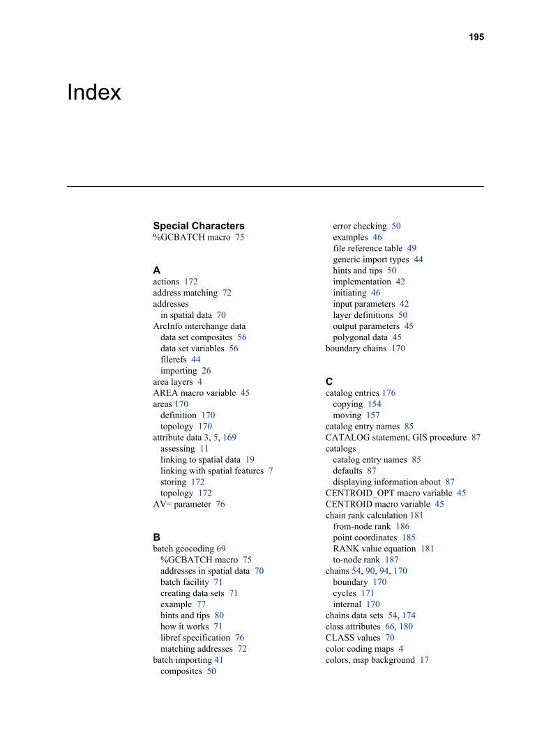
Index
Special Characters%GCBATCH macro 75
Aactions 172address matching 72addresses
in spatial data 70ArcInfo interchange data
data set composites 56data set variables 56filerefs 44importing 26
area layers 4AREA macro variable 45areas 170
definition 170topology 170
attribute data 3, 5, 169assessing 11linking to spatial data 19linking with spatial features 7storing 172topology 172
AV= parameter 76
Bbatch geocoding 69
%GCBATCH macro 75addresses in spatial data 70batch facility 71creating data sets 71example 77hints and tips 80how it works 71libref specification 76matching addresses 72
batch importing 41composites 50
error checking 50examples 46file reference table 49generic import types 44hints and tips 50implementation 42initiating 46input parameters 42layer definitions 50output parameters 45polygonal data 45
boundary chains 170
Ccatalog entries 176
copying 154moving 157
catalog entry names 85CATALOG statement, GIS procedure 87catalogs
catalog entry names 85defaults 87displaying information about 87
CENTROID_OPT macro variable 45CENTROID macro variable 45chain rank calculation 181
from-node rank 186point coordinates 185RANK value equation 181to-node rank 187
chains 54, 90, 94, 170boundary 170cycles 171internal 170
chains data sets 54, 174class attributes 66, 180CLASS values 70color coding maps 4colors, map background 17
195
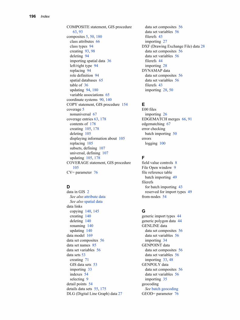
COMPOSITE statement, GIS procedure63, 93
composites 5, 50, 180class attributes 66class types 94creating 93, 98deleting 94importing spatial data 36left/right type 94replacing 94role definition 94spatial databases 65table of 36updating 94, 180variable associations 65
coordinate systems 90, 140COPY statement, GIS procedure 154coverage 5
nonuniversal 67coverage entries 63, 178
contents of 178creating 105, 178deleting 105displaying information about 105replacing 105subsets, defining 107universal, defining 107updating 105, 178
COVERAGE statement, GIS procedure105
CV= parameter 76
Ddata in GIS 2
See also attribute dataSee also spatial data
data linkscopying 140, 145creating 140deleting 140renaming 140updating 140
data model 169data set composites 56data set names 85data set variables 56data sets 53
creating 71GIS data sets 53importing 33indexes 54selecting 9
detail points 54details data sets 55, 175DLG (Digital Line Graph) data 27
data set composites 56data set variables 56filerefs 43importing 27
DXF (Drawing Exchange File) data 28data set composites 56data set variables 56filerefs 44importing 28
DYNAMAP datadata set composites 56data set variables 56filerefs 43importing 28, 50
EE00 files
importing 26EDGEMATCH merges 66, 91edgematching 67error checking
batch importing 50errors
logging 100
Ffield value controls 8File Open window 9file reference table
batch importing 49filerefs
for batch importing 43reserved for import types 49
from-nodes 54
Ggeneric import types 44generic polygon data 44GENLINE data
data set composites 56data set variables 56importing 34
GENPOINT datadata set composites 56data set variables 56importing 33, 48
GENPOLY datadata set composites 56data set variables 56importing 35
geocodingSee batch geocoding
GEOD= parameter 76
196 Index
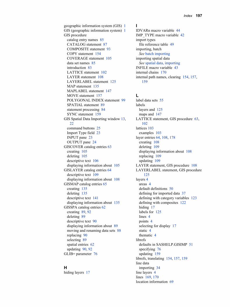
geographic information system (GIS) 1GIS (geographic information system) 1GIS procedure
catalog entry names 85CATALOG statement 87COMPOSITE statement 93COPY statement 154COVERAGE statement 105data set names 85introduction 83LATTICE statement 102LAYER statement 108LAYERLABEL statement 125MAP statement 135MAPLABEL statement 147MOVE statement 157POLYGONAL INDEX statement 99SPATIAL statement 89statement processing 84SYNC statement 159
GIS Spatial Data Importing window 13,22
command buttons 25Import Type field 23INPUT pane 23OUTPUT pane 24
GISCOVER catalog entries 63creating 105deleting 105descriptive text 106displaying information about 105
GISLAYER catalog entries 64descriptive text 109displaying information about 108
GISMAP catalog entries 65creating 135deleting 135descriptive text 141displaying information about 135
GISSPA catalog entries 62creating 89, 92deleting 89descriptive text 90displaying information about 89moving and renaming data sets 88replacing 90selecting 89spatial entries 62updating 90, 92
GLIB= parameter 76
Hhiding layers 17
IIDVARn macro variable 44IMP_TYPE macro variable 42import types
file reference table 49importing, batch
See batch importingimporting spatial data
See spatial data, importingINFILE macro variable 43internal chains 170internal path names, clearing 154, 157,
159
Llabel data sets 55labels
layers and 125maps and 147
LATTICE statement, GIS procedure 63,102
lattices 103examples 103
layer entries 64, 108, 178creating 108deleting 109displaying information about 108replacing 109updating 109
LAYER statement, GIS procedure 108LAYERLABEL statement, GIS procedure
125layers 4
areas 4default definitions 50defining for imported data 37defining with category variables 123defining with composites 122hiding 17labels for 125lines 4points 4selecting for display 17static 4thematic 4
librefsdefaults in SASHELP.GISIMP 51specifying 76updating 159
librefs, translating 154, 157, 159line data
importing 34line layers 4lines 169, 170location information 69
Index 197
Mmap data sets 161
importing 30map entries 65, 135, 179
See also GISMAP catalog entriescontents of 179creating 135, 179deleting 135displaying information about 135, 180replacing 136updating 136
MAP statement, GIS procedure 135MapInfo data
data set composites 56data set variables 56filerefs 44importing 30
MAPLABEL statement, GIS procedure147
mapsbackground colors 17color coding 4coordinate systems 90, 140creating 145defaults 15detail level 18hemispheres 90labels for 147layers 4, 17physical details, and layers 4projections 16saving changes to 20scale mode 17selecting 9showing larger areas 67unit system 17updating 145
MERGE= argumentSPATIAL statement (GIS) 66
merged spatial entries 62, 177merging spatial data 66, 90
benefits of 67EDGEMATCH merges 66edgematching 67hints and tips 67MERGE= argument 66OVERLAP merges 67
MOVE statement, GIS procedure 157
NNEWDATA= parameter 76NIDVARS macro variable 44nodes 90, 94, 170nodes data sets 54, 175nonuniversal coverage 67
NV= parameter 76
OOVERLAP merges 67, 91
PP4Z= parameter 77point data 33point layers 4points 169
SAS/GIS topology 170polygon data
chains 54generic, importing 35importing 45
polygonal index data sets 55, 175creating 99deleting 99keeping 90renaming/moving with host commands
100replacing 99updating 100
POLYGONAL INDEX statement, GISprocedure 63, 99
polylines 174projections 16pull-down controls 8pull-out controls 8PV= parameter 77
RRANK value equation 181RUN-group processing 84
SSAS software
features 2SAS views 54SAS/GIS batch import
See batch importingSAS/GIS data sets 53SAS/GIS interface
field value controls 8pull-down controls 8selecting maps and data sets 9starting SAS/GIS software 8
SAS/GIS softwarestarting 8tutorial 9
SAS/GRAPH datadata set composites 56
198 Index
data set variables 56SAS/GRAPH map data sets
importing 30SASGRAPH import type 44, 48SASHELP.GISIMP data set 39, 51scale mode 17simple spatial entries 62, 176spatial data 3, 11, 169
See also layersaddresses in 70CLASS values 70composites 5coverage 5features 169linking to attribute data 19locating a source of 12merging 90requirements for 12stored coordinates 90tasks for 13themes 19, 123
spatial data, importing 13, 21See also GIS Spatial Data Importing
windowArcInfo interchange data 26composites 36data sets 33DLG data 27DXF data 28DYNAMAP data 28E00 files 26generic line data 34generic point data 33generic polygon data 35generic spatial data 33GENLINE data 34GENPOINT data 33GENPOLY data 35layer definitions 37map data sets 30MapInfo data 30process for 25SASHELP.GISIMP data set 39TIGER data 31
Spatial Data Importing windowSee GIS Spatial Data Importing window
spatial data sets 172spatial databases 172
areas 170catalog entries 176chains data sets 174class attributes 180common level of spatial and attribute
data 7common variables 172COMPOSITE statement 63
composites 65, 180coverage entries 178data model 169designing 6detail amount 7detail definitions 90details data sets 175LATTICE statement 63layer entries 178lines 169linking with attribute data 7managing size of 55map entries 179merging 92nodes data sets 175points 169polygonal index data sets 175POLYGONAL INDEX statement 63sample code for 67spatial entries 176structure 172variable associations 180variable linkages 173
spatial entries 176contents of 176creating 89, 176deleting 89displaying information about 89, 178merged 62, 177replacing 90simple 62, 176updating 90, 177
SPATIAL statement, GIS procedure 89SV= parameter 77SYNC statement, GIS procedure 159
Tthemes 19, 109
creating 115, 123deleting 115replacing 115updating 115, 123
TIGER databatch importing 46, 50data set composites 56data set variables 56filerefs 43importing 31
to-nodes 54topological completeness 170topological correctness 170topological errors 100topological-geometric consistency 171topology 170
areas 170
Index 199
attribute data 172chains 170errors 171lines 170nodes 170points 170topological completeness 171topological-geometric consistency 171
tutorial 9
Uunit system 17
Vvariable associations 65, 180variable linkages 173views 5
ZZIP codes 77ZIPD= parameter 77ZV= parameter 77
200 Index