sai - gs tech catalog
DESCRIPTION
CatalogueTRANSCRIPT
GS Series Motors

Crankshaft DesignRadial Piston Hydraulic Motors
GS SERIESTECHNICAL CATALOG
CONTENTS PAGE
Motor Displacement Table 1
Design Features 2
General Information 4
GS1 Series 9
GS2 Series 13
GS3 Series 17
GS4 Series 21
GS5A Series 25
GS6 Series 29
100103ED1
1
GS
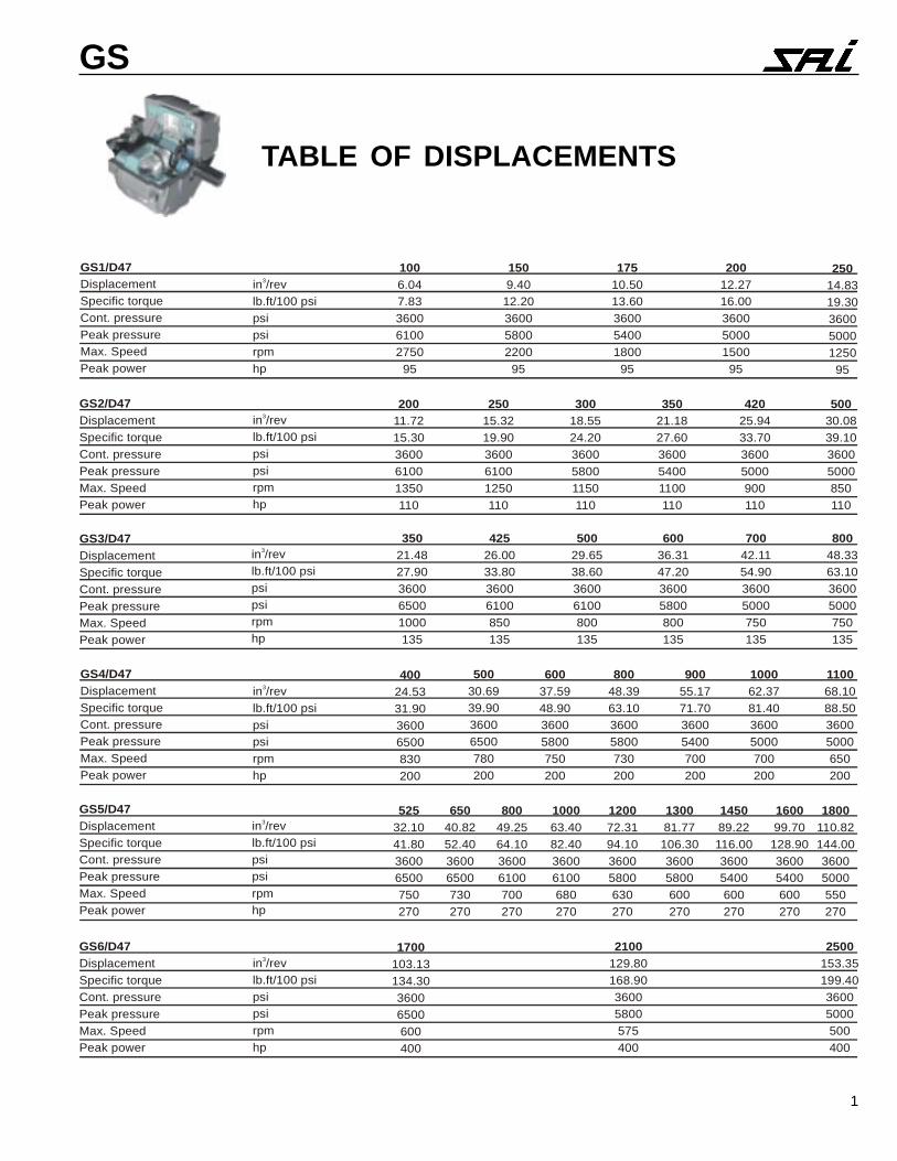
TABLE OF DISPLACEMENTS
in /revlb.ft/100 psipsipsirpmhp
3
1006.047.83360061002750
95
1509.40
12.20360058002200
95
17510.5013.60360054001800
95
20012.2716.00360050001500
95
25014.8319.30360050001250
95
GS1/D47DisplacementSpecific torqueCont. pressurePeak pressureMax. SpeedPeak power
GS2/D47DisplacementSpecific torqueCont. pressurePeak pressureMax. SpeedPeak power
GS3/D47DisplacementSpecific torqueCont. pressurePeak pressureMax. SpeedPeak power
GS4/D47DisplacementSpecific torqueCont. pressurePeak pressureMax. SpeedPeak power
GS5/D47DisplacementSpecific torqueCont. pressurePeak pressureMax. SpeedPeak power
GS6/D47DisplacementSpecific torqueCont. pressurePeak pressureMax. SpeedPeak power
in /revlb.ft/100 psipsipsirpmhp
3
in /revlb.ft/100 psipsipsirpmhp
3
in /revlb.ft/100 psipsipsirpmhp
3
in /revlb.ft/100 psipsipsirpmhp
3
in /revlb.ft/100 psipsipsirpmhp
3
20011.7215.30360061001350110
25015.3219.90360061001250110
30018.5524.20360058001150110
35021.1827.60360054001100110
42025.9433.7036005000900110
50030.0839.1036005000850110
35021.4827.90360065001000135
42526.0033.8036006100850135
50029.6538.6036006100800135
60036.3147.2036005800800135
70042.1154.9036005000750135
80048.3363.1036005000750135
40024.5331.9036006500830200
50030.6939.9036006500780200
60037.5948.9036005800750200
80048.3963.1036005800730200
90055.1771.7036005400700200
100062.3781.4036005000700200
110068.1088.5036005000650200
52532.1041.8036006500750270
65040.8252.4036006500730270
80049.2564.1036006100700270
100063.4082.4036006100680270
120072.3194.1036005800630270
130081.77106.3036005800600270
145089.22116.0036005400600270
160099.70
128.9036005400600270
1800110.82144.0036005000550270
1700103.13134.3036006500600400
2100129.80168.9036005800575400
2500153.35199.4036005000500400

2
GS
HIGH SPEED HIGH PRESSURE HIGH POWER
WIDE CLEARANCEResistance to thermal shockand contamination
HYDROSTATICBALANCINGVery low friction and heatgeneration allows high poweroperation
PISTON SUPPORTBEARINGMinimal sliding speedbetween piston foot andpiston support ring allowshigh speed operation
DISC CAGEThe use of bearing disc cageallows extremely betterperformance in order toreach higher speeds, oralternatively to extendcomponent lifetime
PIVOT CYLINDERNo side load between piston
and cylinder
SURFACE HARDNESS60 HRC
Wear andcontamination resistant
HIGH EFFICIENCY SEALSNo leakage
PISTON RETAINING RINGSPiston remain in full contact with
shaft even with sustainedcavitation or vacuum pressure in
cylinder
CRANKSHAFT DESIGNHigh starting torque
SPHERICAL PISTONSUPPORT RING
High dynamic stability of piston
RADIAL INJECTION CYLINDER FEED
HIGH SPEED
Self-aligning piston
Piston support bearing
Piston retaining ringsHIGH STARTING TORQUE
Crankshaft design
Pivot cylinder
Hydrostatic balancing
High volumetric efficiency
VACUUM FREEWHEELING
Piston retaining rings
Rotating mechanismindependent of pressureconditions
High speed capability
3
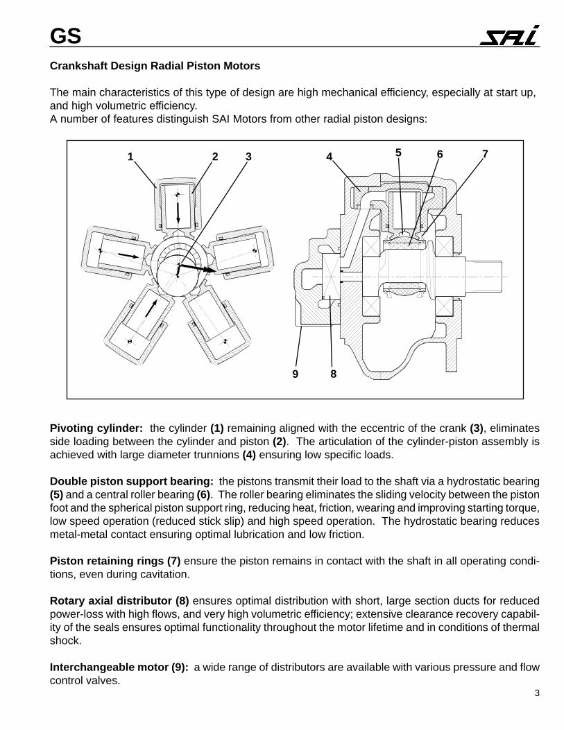
GSCrankshaft Design Radial Piston Motors
The main characteristics of this type of design are high mechanical efficiency, especially at start up,and high volumetric efficiency.A number of features distinguish SAI Motors from other radial piston designs:
Pivoting cylinder: the cylinder (1) remaining aligned with the eccentric of the crank (3), eliminatesside loading between the cylinder and piston (2). The articulation of the cylinder-piston assembly isachieved with large diameter trunnions (4) ensuring low specific loads.
Double piston support bearing: the pistons transmit their load to the shaft via a hydrostatic bearing(5) and a central roller bearing (6). The roller bearing eliminates the sliding velocity between the pistonfoot and the spherical piston support ring, reducing heat, friction, wearing and improving starting torque,low speed operation (reduced stick slip) and high speed operation. The hydrostatic bearing reducesmetal-metal contact ensuring optimal lubrication and low friction.
Piston retaining rings (7) ensure the piston remains in contact with the shaft in all operating condi-tions, even during cavitation.
Rotary axial distributor (8) ensures optimal distribution with short, large section ducts for reducedpower-loss with high flows, and very high volumetric efficiency; extensive clearance recovery capabil-ity of the seals ensures optimal functionality throughout the motor lifetime and in conditions of thermalshock.
Interchangeable motor (9): a wide range of distributors are available with various pressure and flowcontrol valves.
1 32 4 5 6 7
89
4
GS
High SpeedThe GS Series high speed motorshave maximum speeds which aretwo to three times higher than thosenormally expected in LSHT motors.
Low SpeedThe radial piston design ensures ex-cellent low speed characteristics.
High specific speed rangeThe ratio (max speed); (min speed)is higher than any other type ofequivalent hydraulic motor, givinggreater flexibility of application.
High power ratingsThe motors rugged design and highoperating efficiency enable high con-tinuous powers to be transmitted.
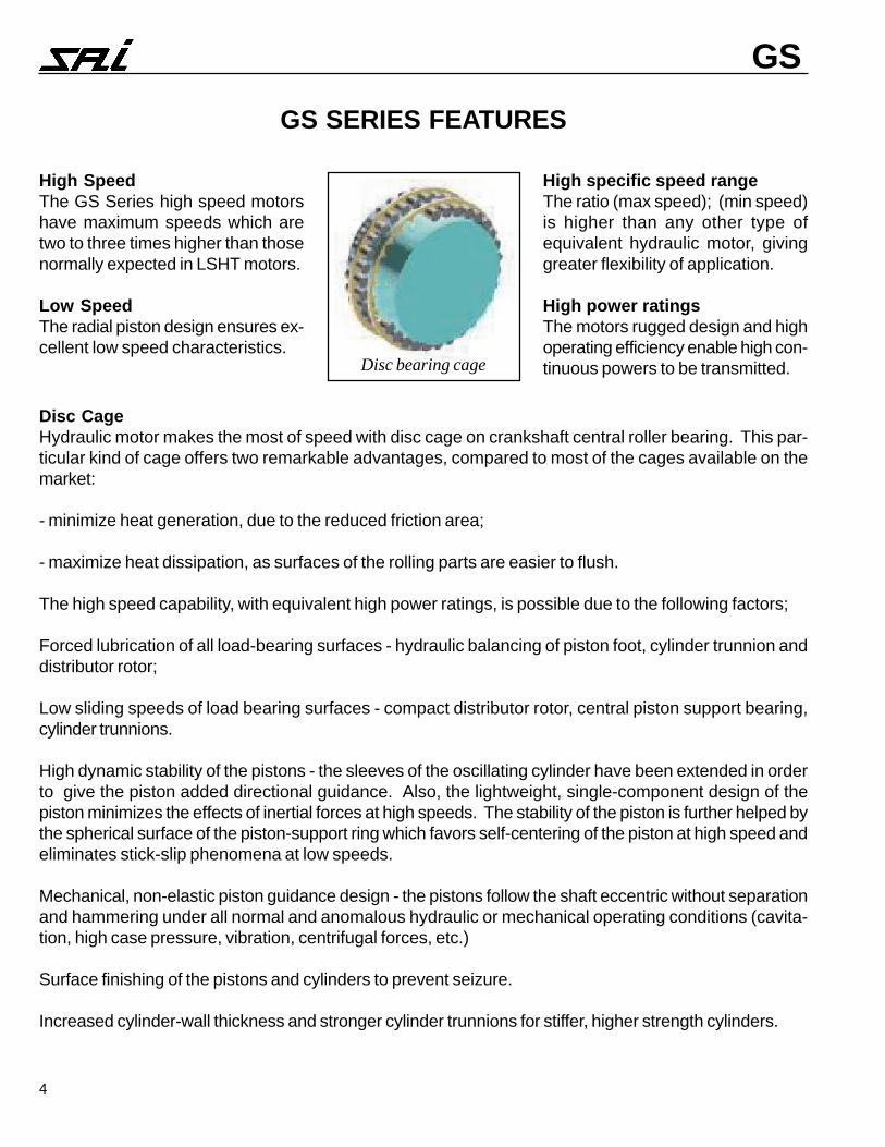
Disc CageHydraulic motor makes the most of speed with disc cage on crankshaft central roller bearing. This par-ticular kind of cage offers two remarkable advantages, compared to most of the cages available on themarket:
- minimize heat generation, due to the reduced friction area;
- maximize heat dissipation, as surfaces of the rolling parts are easier to flush.
The high speed capability, with equivalent high power ratings, is possible due to the following factors;
Forced lubrication of all load-bearing surfaces - hydraulic balancing of piston foot, cylinder trunnion anddistributor rotor;
Low sliding speeds of load bearing surfaces - compact distributor rotor, central piston support bearing,cylinder trunnions.
High dynamic stability of the pistons - the sleeves of the oscillating cylinder have been extended in orderto give the piston added directional guidance. Also, the lightweight, single-component design of thepiston minimizes the effects of inertial forces at high speeds. The stability of the piston is further helped bythe spherical surface of the piston-support ring which favors self-centering of the piston at high speed andeliminates stick-slip phenomena at low speeds.
Mechanical, non-elastic piston guidance design - the pistons follow the shaft eccentric without separationand hammering under all normal and anomalous hydraulic or mechanical operating conditions (cavita-tion, high case pressure, vibration, centrifugal forces, etc.)
Surface finishing of the pistons and cylinders to prevent seizure.
Increased cylinder-wall thickness and stronger cylinder trunnions for stiffer, higher strength cylinders.
Disc bearing cage
GS SERIES FEATURES

5
GS
theoretical torque torque output
PRESSURE RATINGSGS Series motors are rated at a nominal continuous pres-sure rating of 3,600 psi and up to 6,500 psi peak pressure.The continuous and average operating pressure, however,should be chosen in function of the required bearing lifetime(see bearing lifetime graphs). The motors may work at peakpressures for periods not exceeding 1% per minute, no morethan 10 times per hour.Higher continuous and peak pressure ratings can be per-formed. For details contact SAI technical department.
BACK-PRESSUREThe motors are capable of operating with high back-pres-sures with high efficiency, e.g. for series circuit applica-tions.The allowable pressures vary in function piston diameterand other factors. If the motors are required for an appli-cation with high back pressure contact the technical de-partment for further details.Typical allowable back-pressure
Port A Port BCont. 3,000 psi 2,200 psiPeak 5,200 psi 5,200 psi
CASE PRESSUREContinuous case pressure: 15 psiPeak case pressure: 75 psiThe case pressure is independent of the return line pres-sure. For higher pressures (up to 200 psi) contact the tech-nical department.
TORQUETo obtain the theoretical output torque of a motor, multiplythe specific torque (lb.ft/psi) given in the displacementtables by the pressure (psi).The graph below shows the output torque variation as theshaft rotates through 360°.
STARTING TORQUETypical starting torque efficiencies are given in the perfor-mance graphs of the motors. The starting torque, how-ever, also depends on the starting position of the shaft(see graph above).
2-SPEED OPERATIONFor applications containing at least two drive units thatrequire 2-speed operation, SAI can supply the flow con-trol valves for a series-parallel circuit with speed differen-tial also in series mode.The series-parallel directional valve DV5 enables dynamicswitching from parallel circuit configuration (high torque, lowspeed) to series configuration (high speed, low torque).The B5 proportional pressure reducing valve (1) simulatesthe differential effect of the parallel circuit enabling vehiclesto be steered also when operating in series mode.Directional valve (3) can be used as differential lock in con-ditions of poor traction. This valve must be in the closedposition when the motors are connected in parallel.
NOISE LEVELSThe motors operate at lowest noise levels with a back-pres-sure of 75-150 psi, such as in closed circuits. Pressurelines and motor support structures can be efficient noisepropagators or amplifiers. Pressure lines should preferablybe made up of straight rigid lengths, flexible corners, firmlyfixed to rigid supports at irregular intervals away from sheetpanelling. Motors must be rigidly fixed to solid supports.
SILENT MOTORSMotors can be supplied with special distributor that runnearly silently in a wide operating range.Please contact technical department for further details.
VIBRATIONThe motors can be supplied with a counterbalanced shaftto reduce vibrations at high speeds.Please contact technical department for further details.
SPEED STABILITYThe motors are capable of operating at low speeds with ahigh degree of speed stability. The minimum stable speeddepends on the displacement of the motor. In general themotors remain sensitive to flows of 0.1 qt/min + motor leak-age rate. Best results are obtained with 75 - 150 psi back-pressure and after the circuit has been completely purgedof air by running it at 2/3 max speed for 5 - 10 minutes.
A B
Pb B
APa
M
Pm
1 2
34
6
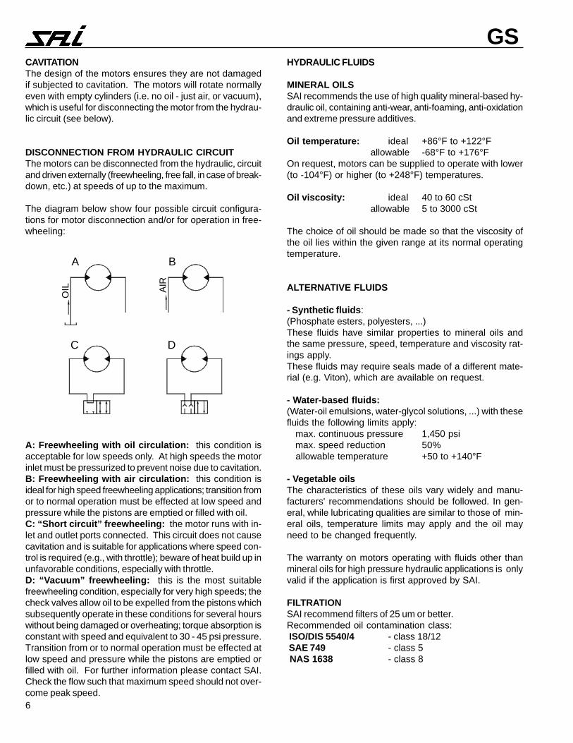
GSCAVITATIONThe design of the motors ensures they are not damagedif subjected to cavitation. The motors will rotate normallyeven with empty cylinders (i.e. no oil - just air, or vacuum),which is useful for disconnecting the motor from the hydrau-lic circuit (see below).
DISCONNECTION FROM HYDRAULIC CIRCUITThe motors can be disconnected from the hydraulic, circuitand driven externally (freewheeling, free fall, in case of break-down, etc.) at speeds of up to the maximum.
The diagram below show four possible circuit configura-tions for motor disconnection and/or for operation in free-wheeling:
A: Freewheeling with oil circulation: this condition isacceptable for low speeds only. At high speeds the motorinlet must be pressurized to prevent noise due to cavitation.B: Freewheeling with air circulation: this condition isideal for high speed freewheeling applications; transition fromor to normal operation must be effected at low speed andpressure while the pistons are emptied or filled with oil.C: “Short circuit” freewheeling: the motor runs with in-let and outlet ports connected. This circuit does not causecavitation and is suitable for applications where speed con-trol is required (e.g., with throttle); beware of heat build up inunfavorable conditions, especially with throttle.D: “Vacuum” freewheeling: this is the most suitablefreewheeling condition, especially for very high speeds; thecheck valves allow oil to be expelled from the pistons whichsubsequently operate in these conditions for several hourswithout being damaged or overheating; torque absorption isconstant with speed and equivalent to 30 - 45 psi pressure.Transition from or to normal operation must be effected atlow speed and pressure while the pistons are emptied orfilled with oil. For further information please contact SAI.Check the flow such that maximum speed should not over-come peak speed.
HYDRAULIC FLUIDS
MINERAL OILSSAI recommends the use of high quality mineral-based hy-draulic oil, containing anti-wear, anti-foaming, anti-oxidationand extreme pressure additives.
Oil temperature: ideal +86°F to +122°F allowable -68°F to +176°F
On request, motors can be supplied to operate with lower(to -104°F) or higher (to +248°F) temperatures.
Oil viscosity: ideal 40 to 60 cSt allowable 5 to 3000 cSt
The choice of oil should be made so that the viscosity ofthe oil lies within the given range at its normal operatingtemperature.
ALTERNATIVE FLUIDS
- Synthetic fluids:(Phosphate esters, polyesters, ...)These fluids have similar properties to mineral oils andthe same pressure, speed, temperature and viscosity rat-ings apply.These fluids may require seals made of a different mate-rial (e.g. Viton), which are available on request.
- Water-based fluids:(Water-oil emulsions, water-glycol solutions, ...) with thesefluids the following limits apply: max. continuous pressure 1,450 psi max. speed reduction 50% allowable temperature +50 to +140°F
- Vegetable oilsThe characteristics of these oils vary widely and manu-facturers' recommendations should be followed. In gen-eral, while lubricating qualities are similar to those of min-eral oils, temperature limits may apply and the oil mayneed to be changed frequently.
The warranty on motors operating with fluids other thanmineral oils for high pressure hydraulic applications is onlyvalid if the application is first approved by SAI.
FILTRATIONSAI recommend filters of 25 um or better.Recommended oil contamination class: ISO/DIS 5540/4 - class 18/12 SAE 749 - class 5 NAS 1638 - class 8
A B
C D
OIL AI
R

7
GS
BRONZE COMPONENTSStandard SAI distributors contain bronze components. Noother part contains bronze components
DIRECTION OF SHAFT ROTATION (Fig. 1)All motors are bi-directional. The direction of shaft rotationis determined by the direction of oil flow. Standard motorsare supplied so that flow entering in Port A causes the shaftto rotate clockwise (as seen from the shaft side of the mo-tor). Flow entering Port B causes anticlockwise rotation.Motors can be supplied with the reverse configuration: seemotor order codes.
DRAIN-LINE POSITIONING (Fig. 2)The drain-line must be positioned in such a way that thereis always sufficient oil in the casing for the lubrication of thedynamic components in the motor.If the motor is installed with the shaft in a horizontal posi-tion, the drain-line should be connected to the uppermostdrain-line port.The drain-line should be of a diameter corresponding to thesize of the drain line port and flow must not be obstructedby sharp corners, restrictions, etc.Standard motors are supplied with drain port Y (Fig. 3) closed(zinc plated HH plug) and drain port X open (with plasticplug). Motors can be supplied with Y-open, X-closed.
DISTRIBUTOR COVER ORIENTATION (Fig. 3)Motors may be supplied with the distributor assembled withthe arrow pointing towards any one of the five pistons. Toorder, use assembly code DM1, DM2, DM3, etc.(DM1 = standard)
START-UPBefore connecting any tubes ensure that they are thoroughlycleaned, any excess material that could work loose shouldbe removed and there should not be any oxidation of sur-faces that come into contact with the oil.Before starting work the motor casing must be filled with oil.Before starting work the hydraulic circuit should be purgedof air. This can be achieved by running the motor withoutload for 10-20 minutes, during which time checks should bemade for leakages from connections.During the first few hours of working under load checks shouldbe made for leakages from connections and to ensure thatall components remain firmly fixed to their supports.All motors are factory tested and do not require to be run in.
Fig.1 Direction of shaft rotation
Fig.2 Drain line positioning
Fig.3 Distributor cover orientation

8
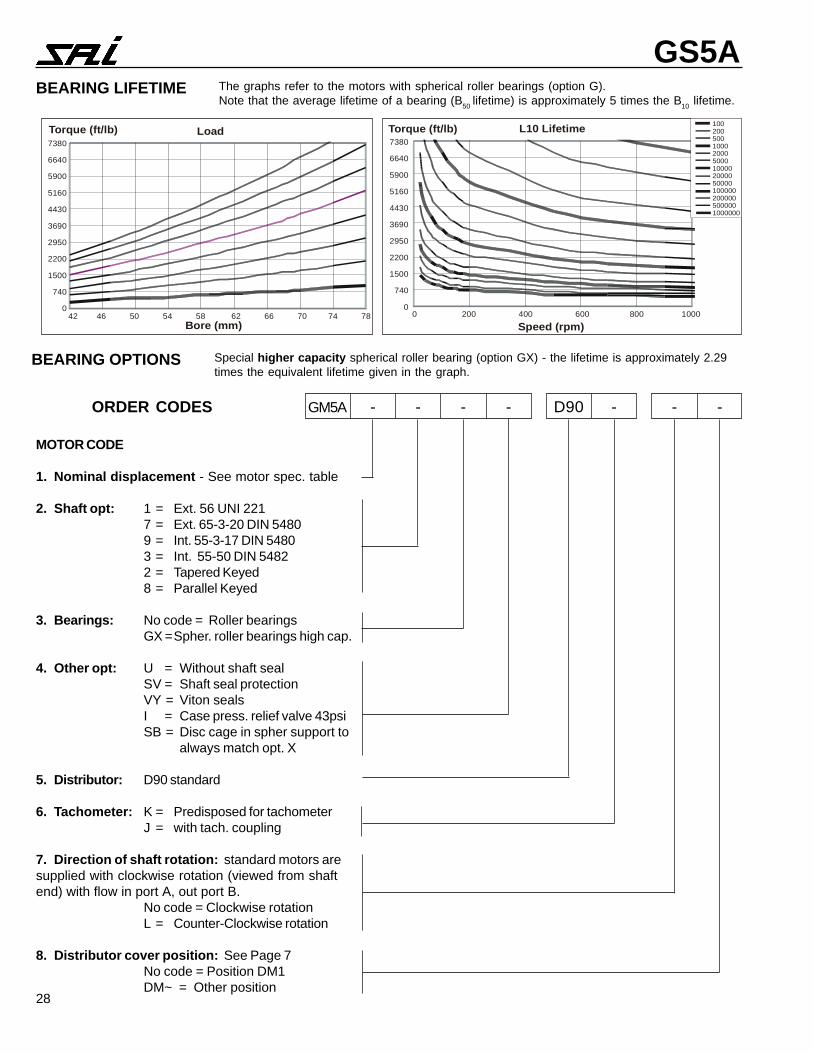
GSBEARING LIFETIME (As per ISO 287:1990)The bearing lifetimes given in this catalogue are L10 life-times. The L10 lifetime is the period of work after which 10%of the bearings can be expected to show signs of wearing.The average lifetime of the bearing, the L50 lifetime (where50% of the bearings show signs of wearing), is approxi-mately 5 times the L10 value.
To determine the lifetime of the bearings in an application,constant or average pressures and speeds should be used,not peak or max values. The continuous operating pres-sures of any motor should be chosen in function of the re-quired motor lifetime.
Bearing Lifetime GraphsThe bearing lifetime graphs enable the bearing lifetime to becalculated for a given power input and speed output. If nec-essary use the power charts to determine the power inputfor a given pressure.
If the calculated lifetime is insufficient, please contactSAI technical department.
MOTOR LIFETIME REQUIREMENTThe required bearing lifetime may be calculated using thefollowing formula:Life (hours) = Hours of work per day x Days work per yearx No. of years x Correction factor
Correction factor: The calculated lifetime of the bear-ings presumes favorable lubrication conditions with oilhaving values of temperature, viscosity and oil cleanlinessthat lie within the given ranges.A correction factor should be applied for applications, forexample including continuous duty over several hours,where high oil temperatures or other anomalous workingconditions can occur.The table below indicates the correction factor to be ap-plied in function of the duration of the cycle of continuouswork, for applications in which the working conditions ofthe oil are not regularly checked.
Non-StopWork Cycle (hrs) <3 6 12 18 24
Correction Factor 1 1.25 1.5 2 3
PRESSURE-LIFETIME RELATIONSHIP
Please note that a small variation in thepressure used to calculate the lifetime canproduce a large difference in the calcu-lated lifetime.The relationship between the workingpressure and the lifetime is not linear, butas shown in the graph.
Example:If, with 1000 psi (load factor =1), the lifetime is 10,000 hours(lifetime factor = 1), then with1200 psi (load factor = 1.2)the lifetime becomes 5500hours (lifetime factor 0.55)
1002005001000200050001000020000500001000002000005000001000000
0
750
1500
2200
3000
3700
4400
5100 Torque [ft/lb]
5000 psi
4500 psi
3500 psi
3000 psi2000 psi1500 psi1000 psi
Load Torque [ft/lb] L10 Lifetime
0
750
1500
2200
3000
3700
4400
5100
Bore (mm) Speed (rpm)40 45 50 55 60 65 70 0 100 200 300 400 500 600 700 800 900 1000
9
GS1
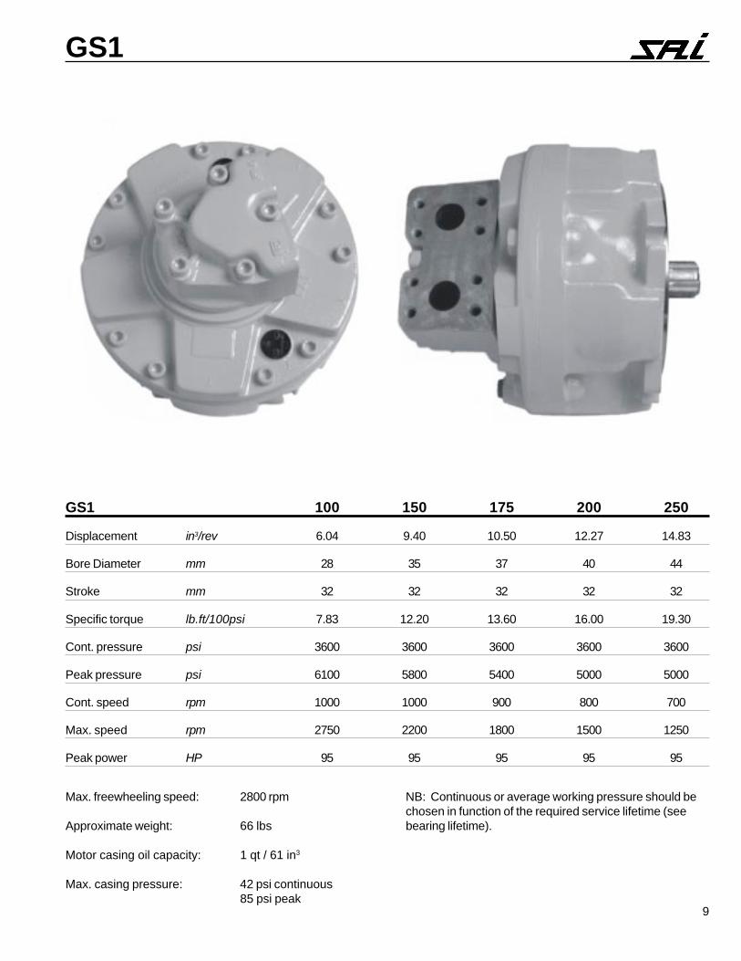
GS1 100 150 175 200 250
Displacement in3/rev 6.04 9.40 10.50 12.27 14.83
Bore Diameter mm 28 35 37 40 44
Stroke mm 32 32 32 32 32
Specific torque lb.ft/100psi 7.83 12.20 13.60 16.00 19.30
Cont. pressure psi 3600 3600 3600 3600 3600
Peak pressure psi 6100 5800 5400 5000 5000
Cont. speed rpm 1000 1000 900 800 700
Max. speed rpm 2750 2200 1800 1500 1250
Peak power HP 95 95 95 95 95
Max. freewheeling speed: 2800 rpm
Approximate weight: 66 lbs
Motor casing oil capacity: 1 qt / 61 in3
Max. casing pressure: 42 psi continuous85 psi peak
NB: Continuous or average working pressure should bechosen in function of the required service lifetime (seebearing lifetime).
10
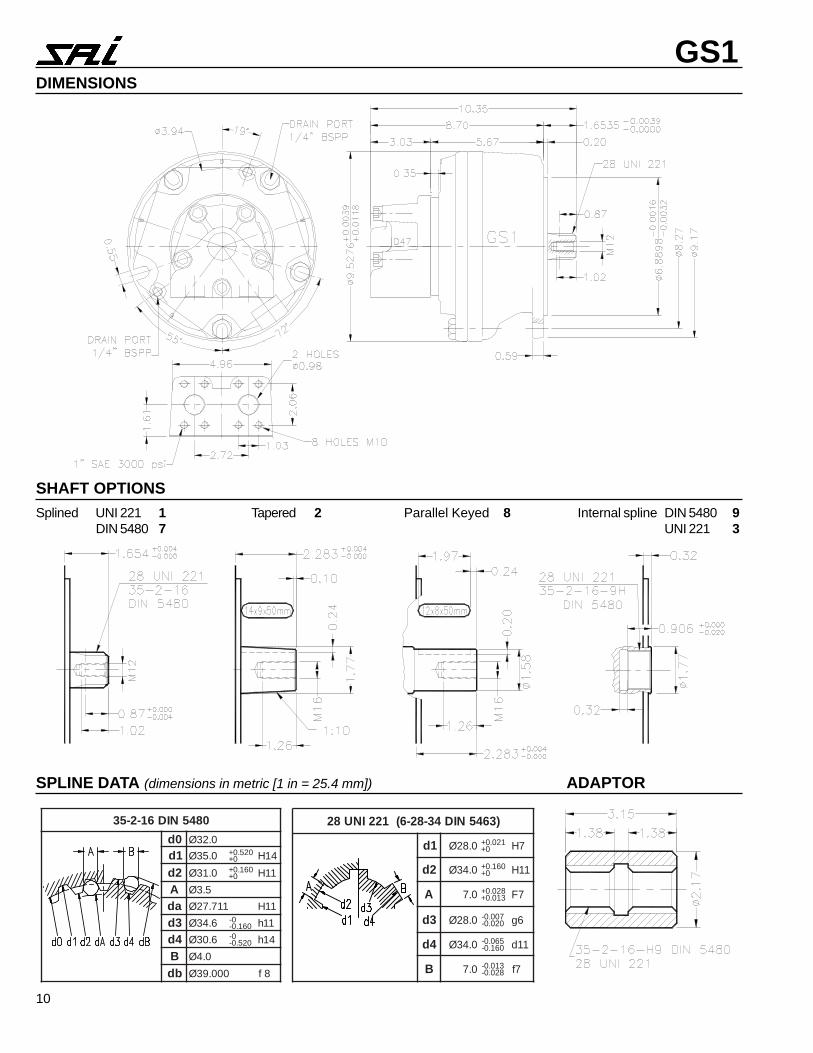
GS1DIMENSIONS
SHAFT OPTIONS
SPLINE DATA (dimensions in metric [1 in = 25.4 mm]) ADAPTOR
Splined UNI 221 1 Tapered 2 Parallel Keyed 8 Internal spline DIN 5480 9DIN 5480 7 UNI 221 3
0845NID61-2-530d 0.23Ø1d 0.53Ø 025.0+
0+ 41H2d 0.13Ø 061.0+
0+ 11HA 5.3Øad 117.72Ø 11H3d 6.43Ø 0-
061.0- 11h4d 6.03Ø 0-
025.0- 41hB 0.4Øbd 000.93Ø 8f
)3645NID43-82-6(122INU82
1d 0.82Ø 120.0+0+ 7H
2d 0.43Ø 061.0+0+ 11H
A 0.7 820.0+310.0+ 7F
3d 0.82Ø 700.0-020.0- 6g
4d 0.43Ø 560.0-061.0- 11d
B 0.7 310.0-820.0- 7f
11
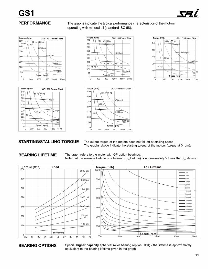
GS1PERFORMANCE The graphs indicate the typical performance characteristics of the motors
operating with mineral oil (standard ISO 68).
The graph refers to the motor with GP option bearings.Note that the average lifetime of a bearing (B50 lifetime) is approximately 5 times the B10 lifetime.
BEARING LIFETIME
Special higher capacity spherical roller bearing (option GPX) - the lifetime is approximatelyequivalent to the bearing lifetime given in the graph.
BEARING OPTIONS
00 500 1000 1500 2000 2500
Torque (ft/lb) GS1 100 - Power Chart
Speed [rpm]
6000 psi
4500 psi
3000 psi
1500 psi
520
440
370
300
220
150
75
15 hp 30 hp55 hp 95 hp
GS1 150 Power ChartTorque (ft/lb)
15 hp30 hp
55 hp 95 hp6000 psi
4500 psi
3000 psi
1500 psi
740
660
590
520
440
370
300
220
150
75
0Speed (rpm)
0 400 800 1200 1600 2000
-
GS1 175 Power ChartTorque (ft/lb)
15 hp
30 hp
55 hp 95 hp
Speed (rpm)
6000 psi
4500 psi
3000 psi
1500 psi
740
590
440
300
150
00 350 700 1050 1400 1750
GS1 250 Power ChartTorque (ft/lb)
15 hp
30 hp
55 hp 95 hp
4500 psi
3000 psi
1500 psi
Speed (rpm)
1030
890
740
590
440
300
150
00 250 500 750 1000 1250
1002005001000200050001000020000500001000002000005000001000000
LoadTorque (ft/lb)1030
890
740
590
440
300
150
0
5000 psi
4500 psi
4000 psi
3000 psi
2000 psi
1500 psi
100 psi
Bore (mm)
25 27 29 31 33 35 37 39 41 43 45
1030
890
740
590
440
300
150
0
Torque (ft/lb) L10 Lifetime
Speed (rpm)0 500 1000 1500 2000 2500
STARTING/STALLING TORQUE The output torque of the motors does not fall off at stalling speed.The graphs above indicate the starting torque of the motors (torque at 0 rpm).
GS1 200 Power ChartTorque (ft/lb)
15 hp30 hp
55 hp 95 hp
Speed (rpm)
810740660590520440370300220150
750
0 300 600 900 1200 1500
4500 psi
3000 psi
1500 psi
12
GS1
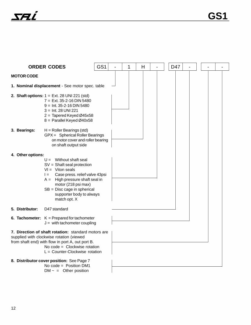
ORDER CODES GS1 - 1 H - D47 - - -
MOTOR CODE
1. Nominal displacement - See motor spec. table
2. Shaft options: 1 = Ext. 28 UNI 221 (std)7 = Ext. 35-2-16 DIN 54809 = Int. 35-2-16 DIN 54803 = Int. 28 UNI 2212 = Tapered Keyed Ø45x588 = Parallel Keyed Ø40x58
3. Bearings: H = Roller Bearings (std)GPX = Spherical Roller Bearings
on motor cover and roller bearingon shaft output side
4. Other options:U = Without shaft sealSV = Shaft seal protectionVI = Viton sealsI = Case press. relief valve 43psiA = High pressure shaft seal in
motor (218 psi max)SB = Disc cage in spherical
supporter body to alwaysmatch opt. X
5. Distributor: D47 standard
6. Tachometer: K = Prepared for tachometerJ = with tachometer coupling
7. Direction of shaft rotation: standard motors aresupplied with clockwise rotation (viewedfrom shaft end) with flow in port A, out port B.
No code = Clockwise rotationL = Counter-Clockwise rotation
8. Distributor cover position: See Page 7No code = Position DM1DM ~ = Other position

13
GS2
Max. freewheeling speed: 2000 rpm
Approximate weight: 114 lbs
Motor casing oil capacity: 2 qt / 122 in3
Max. casing pressure: 42 psi continuous85 psi peak
NB: Continuous or average working pressure should bechosen in function of the required service lifetime (see bear-ing lifetime).
GS2 200 250 300 350 420 500
Displacement in3/rev 11.72 15.32 18.55 21.18 25.94 30.08
Bore diameter mm 35 40 44 47 52 56
Stroke mm 40 40 40 40 40 40
Specific torque lb.ft/100psi 15.30 19.90 24.20 27.60 33.70 39.10
Cont. pressure 1) psi 3600 3600 3600 3600 3600 3600
Peak pressure psi 6100 6100 5800 5400 5000 5000
Cont. speed rpm 900 700 650 600 525 525
Max. speed 3) rpm 1350 1250 1150 1100 900 850
Peak power HP 110 110 110 110 110 110

14
GS2DIMENSIONS
SHAFT OPTIONSSplined DIN 5480 7
UNI 220 1Tapered 2 Parallel Keyed 8 Internal Spline DIN 5480 9
UNI 220 3
SPLINE DATA (dimensions in mm [1 in = 25.4 mm]) ADAPTOR
0845NID21-3-04
0d 0.63Ø
1d 0.04Ø 026.0+0+ 41H
2d 0.43Ø 061.0+0+ 11H
A 52.5Ø
ad 69.82Ø 031.0+0+ 11H
3d 4.93Ø 0-061.0- 11h
4d 4.33Ø 0-026.0- 41h
B 0.6Ø
bd 989.54Ø 520.0-460.0- 8f
)2645NID(022INU63
1d 0.63Ø 520.0+0+ 7H
2d 0.04Ø 061.0+0+ 11H
A 0.7 820.0+310.0+ 7F
3d 0.63Ø 900.0-520.0- 6g
4d 0.04Ø 080.0-042.0- 11d
B 0.7 310.0-820.0- 7f
15
GS2
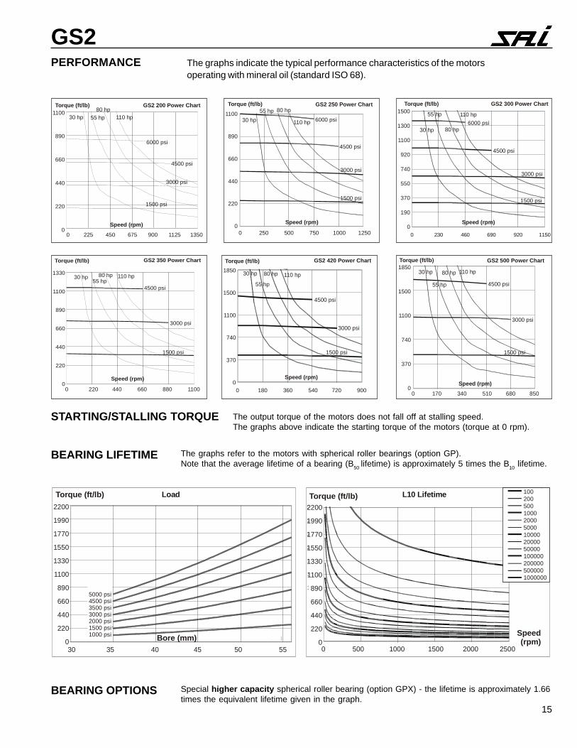
STARTING/STALLING TORQUE The output torque of the motors does not fall off at stalling speed.The graphs above indicate the starting torque of the motors (torque at 0 rpm).
PERFORMANCE The graphs indicate the typical performance characteristics of the motorsoperating with mineral oil (standard ISO 68).
The graphs refer to the motors with spherical roller bearings (option GP).Note that the average lifetime of a bearing (B50 lifetime) is approximately 5 times the B10 lifetime.
BEARING LIFETIME
Special higher capacity spherical roller bearing (option GPX) - the lifetime is approximately 1.66times the equivalent lifetime given in the graph.
BEARING OPTIONS
GS2 200 Power ChartTorque (ft/lb)
Speed (rpm)
30 hp 55 hp80 hp
110 hp
6000 psi
4500 psi
3000 psi
1500 psi
0 225 450 675 900 1125 1350
1100
890
660
440
220
0
GS2 250 Power ChartTorque (ft/lb)
Speed (rpm)
30 hp55 hp 80 hp
110 hp
0 250 500 750 1000 1250
6000 psi
4500 psi
3000 psi
1500 psi
1100
890
660
440
220
00 230 460 690 920 1150
GS2 300 Power ChartTorque (ft/lb)
Speed (rpm)
30 hp
55 hp
80 hp
110 hp6000 psi
4500 psi
3000 psi
1500 psi
1500
1300
1100
920
740
550
370
190
0
GS2 350 Power ChartTorque (ft/lb)
Speed (rpm)
4500 psi
3000 psi
1500 psi
0 220 440 660 880 1100
30 hp55 hp
80 hp 110 hp1330
1100
890
660
440
220
0
GS2 420 Power ChartTorque (ft/lb)
Speed (rpm)
30 hp
55 hp
80 hp 110 hp
4500 psi
3000 psi
1500 psi
0 180 360 540 720 900
1850
1500
1100
740
370
0
GS2 500 Power ChartTorque (ft/lb)
Speed (rpm)
30 hp
55 hp
80 hp 110 hp
0 170 340 510 680 850
4500 psi
3000 psi
1500 psi
1850
1500
1100
740
370
0
L10 Lifetime
0
300
600
900
1200
1500
1800
2100
2400
2700
3000
0 500 1000 1500 2000 2500Speed [rpm]
Torque [Nm]100
200
500
1000
2000
5000
10000
20000
50000
100000
200000
500000
1000000
Load
50bar100bar
150bar200bar250bar300bar350bar
0
300
600
900
1200
1500
1800
2100
2400
2700
3000
30 35 40 45 50 55
Bore [mm]
Torque [Nm]Torque (ft/lb)2200
1990
1770
1550
1330
1100
890
660
440
220
0
5000 psi4500 psi3500 psi3000 psi2000 psi1500 psi1000 psi Bore (mm)
2200
1990
1770
1550
1330
1100
890
660
440
220
0
Torque (ft/lb)
Speed(rpm)
30 35 40 45 50 55 0 500 1000 1500 2000 2500
1002005001000200050001000020000500001000002000005000001000000
16
GS2
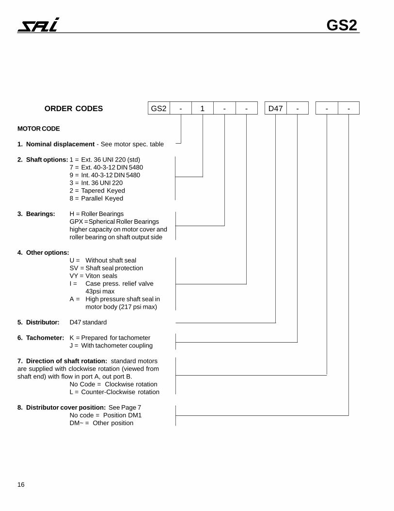
MOTOR CODE
1. Nominal displacement - See motor spec. table
2. Shaft options: 1 = Ext. 36 UNI 220 (std)7 = Ext. 40-3-12 DIN 54809 = Int. 40-3-12 DIN 54803 = Int. 36 UNI 2202 = Tapered Keyed8 = Parallel Keyed
3. Bearings: H = Roller BearingsGPX =Spherical Roller Bearingshigher capacity on motor cover androller bearing on shaft output side
4. Other options:U = Without shaft sealSV = Shaft seal protectionVY = Viton sealsI = Case press. relief valve
43psi maxA = High pressure shaft seal in
motor body (217 psi max)
5. Distributor: D47 standard
6. Tachometer: K = Prepared for tachometerJ = With tachometer coupling
7. Direction of shaft rotation: standard motorsare supplied with clockwise rotation (viewed fromshaft end) with flow in port A, out port B.
No Code = Clockwise rotationL = Counter-Clockwise rotation
8. Distributor cover position: See Page 7No code = Position DM1DM~ = Other position
ORDER CODES GS2 - 1 - - D47 - - -

17
GS3
Max. freewheeling speed 1600 rpm
Approximate weight: 191 lbs
Motor casing oil capacity: 1.3 gal / 305 in3
Max. casing pressure: 42 psi continuous85 psi peak
NB: Continuous or average working pressure should bechosen in function of the required service lifetime (see bear-ing lifetime).
GS3 350 425 500 600 700 800*Displacement in3/rev 21.48 26.00 29.65 36.31 42.11 48.33
Bore diameter mm 40 44 47 52 56 60
Shaft mm 56 56 56 56 56 56
Specific torque lb.ft/100psi 27.90 33.80 38.60 47.20 54.90 63.10
Cont. pressure psi 3600 3600 3600 3600 3600 3600
Peak pressure psi 6500 6100 6100 5800 5000 5000
Cont. speed rpm 575 550 500 400 375 375
Max. speed rpm 1000 850 800 800 750 750
Peak power HP 135 135 135 135 135 135
* available under SAI approval of the application

18
GS3DIMENSIONS
SHAFT OPTIONSSplined DIN 5480 7
UNI 221 1Tapered 2 Parallel Keyed 8 Internal DIN 5480 9
Spline UNI 220 3
SPLINE DATA (dimensions in mm [1 in = 25.4 mm]) ADAPTOR
0845NID21-3-04
0d 0.63Ø
1d 0.04Ø 026.0+0+ 41H
2d 0.43Ø 061.0+0+ 11H
A 52.5Ø
ad 69.82Ø 031.0+0+ 11H
3d 4.93Ø 0-061.0- 11h
4d 4.33Ø 0-026.0- 41h
B 0.6Ø
bd 989.54Ø 520.0-460.0- 8f
)3645NID45-64-8(122INU64
1d 0.64Ø 520.0+0+ 7H
2d 0.45Ø 091.0+0+ 11H
A 0.9 820.0+310.0+ 7F
3d 0.64Ø 900.0-520.0- 6g
4d 0.45Ø 001.0-092.0- 11d
B 0.9 310.0-820.0- 7f
See page 14 for 36 UNI 220spline data.

19
GS3PERFORMANCE The graphs indicate the typical performance characteristics of the motors
operating with mineral oil (standard ISO 68).
STARTING/STALLING TORQUE The output torque of the motors does not fall off at stalling speed.The graphs above indicate the starting torque of the motors (torque at 0 rpm).
The graphs refer to the motors with spherical roller bearings (option GP).Note that the average lifetime of a bearing (B50 lifetime) is approximately 5 times the B10 lifetime.
BEARING LIFETIME
Special higher capacity spherical roller bearing (option GPX) - the lifetime is approximately 1.36times the equivalent lifetime given in the graph.
BEARING OPTIONS
GS3 350 Power ChartTorque (ft/lb)
Speed (rpm)
35 hp70 hp100 hp 135 hp
0 200 400 600 800 1000
6000 psi
4500 psi
3000 psi
1500 psi
1850
1500
1100
740
370
0
GS3 425 Power ChartTorque (ft/lb)
Speed (rpm)
6000 psi
4500 psi
3000 psi
1500 psi
35 hp
70 hp
100 hp 135 hp
0 170 340 510 680 850
2200
1770
1330
890
440
0
Torque (ft/lb)
Speed (rpm)
GS3 500 Power Chart
35 hp70 hp
100 hp135 hp
6000 psi
4500 psi
3000 psi
1500 psi
0 156 312 468 624 780
2580
2070
1550
1030
520
0
Torque (ft/lb) GS3 600 Power Chart
Speed (rpm)
35 hp70 hp
100 hp
135 hp6000 psi
4500 psi
3000 psi
1500 psi
0 160 320 480 640 800
2950
2360
1770
1180
660
0
GS3 700 Power ChartTorque (ft/lb)
Speed (rpm)
55 hp
80 hp
115 hp135 hp
4500 psi
3000 psi
1500 psi
0 150 300 450 600 750
2950
2360
1770
1180
660
0
GS3 800 Power ChartTorque (ft/lb)
Speed (rpm)
40 hp
70 hp
100 hp135 hp
4500 psi
3000 psi
1500 psi
0 150 300 450 600 750
2800
2240
1680
1120
550
0
Load
50BAR
100BAR150BAR200BAR
250BAR300BAR
350BAR
0
500
1000
1500
2000
2500
3000
3500
4000
4500
5000
35 40 45 50 55 60
Bore[mm]
Torque[Nm] L10Lifetime
0
500
1000
1500
2000
2500
3000
3500
4000
4500
5000
0 500 1000 1500 2000 2500
Speed[rpm]
Torque[Nm]
100
200
500
1000
2000
5000
10000
20000
50000
100000
200000
500000
1000000
Torque (ft/lb)3690
3320
2950
2580
2200
1850
1500
1100
740
370
0
5000 psi4500 psi3500 psi3000 psi2000 psi1500 psi1000 psi Bore (mm)
35 40 45 50 55 60
Speed(rpm)0 500 1000 1500 2000 2500
1002005001000200050001000020000500001000002000005000001000000
20
GS3
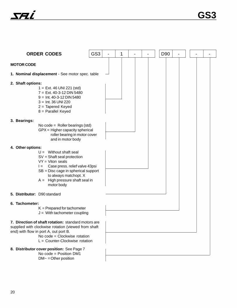
MOTOR CODE
1. Nominal displacement - See motor spec. table
2. Shaft options:1 = Ext. 46 UNI 221 (std)7 = Ext. 40-3-12 DIN 54809 = Int. 40-3-12 DIN 54803 = Int. 36 UNI 2202 = Tapered Keyed8 = Parallel Keyed
3. Bearings:No code = Roller bearings (std)GPX = Higher capacity spherical
roller bearing in motor coverand in motor body
4. Other options:U = Without shaft sealSV = Shaft seal protectionVY = Viton sealsI = Case press. relief valve 43psiSB = Disc cage in spherical support
to always matchopt. XA = High pressure shaft seal in
motor body
5. Distributor: D90 standard
6. Tachometer:K = Prepared for tachometerJ = With tachometer coupling
7. Direction of shaft rotation: standard motors aresupplied with clockwise rotation (viewed from shaftend) with flow in port A, out port B.
No code = Clockwise rotationL = Counter-Clockwise rotation
8. Distributor cover position: See Page 7No code = Position DM1DM~ = Other position
ORDER CODES GS3 - 1 - - D90 - - -
21
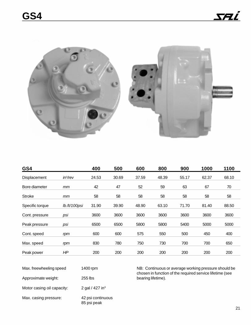
GS4
Max. freewheeling speed 1400 rpm
Approximate weight: 255 lbs
Motor casing oil capacity: 2 gal / 427 in3
Max. casing pressure: 42 psi continuous85 psi peak
GS4 400 500 600 800 900 1000 1100Displacement in3/rev 24.53 30.69 37.59 48.39 55.17 62.37 68.10
Bore diameter mm 42 47 52 59 63 67 70
Stroke mm 58 58 58 58 58 58 58
Specific torque lb.ft/100psi 31.90 39.90 48.90 63.10 71.70 81.40 88.50
Cont. pressure psi 3600 3600 3600 3600 3600 3600 3600
Peak pressure psi 6500 6500 5800 5800 5400 5000 5000
Cont. speed rpm 600 600 575 550 500 450 400
Max. speed rpm 830 780 750 730 700 700 650
Peak power HP 200 200 200 200 200 200 200
NB: Continuous or average working pressure should bechosen in function of the required service lifetime (seebearing lifetime).

22
GS4DIMENSIONS
SHAFT OPTIONSSplined DIN 5480 7
UNI 221 1Tapered 2 Parallel Keyed 8 Internal DIN 5480 9
Spline DIN 5482 3
SPLINE DATA (dimensions in mm [1 in = 25.4 mm]) ADAPTORNID
0845NID02-3-56 2845NID62-2-55 0845NID71-3-55 122INU65
0d 0.06Ø 0.25Ø 0.15Ø 1d 0.65Ø 030.0+0+ 7H
1d 0.56Ø 047.0+0+ 41H 0.55Ø 0030+
0+ 21H 0.55Ø 047.0+0+ 41H 2d 0.56Ø 091.0+
0+ 11H
2d 0.95Ø 091.0+0+ 11H 0.05Ø 061.0+
0+ 11H 0.94Ø 061.0+0+ 11H A 0.01 820.0+
310.0+ 7F
A 52.5Ø 5.3Ø 52.5Ø 3d 0.65Ø 010.0-920.0- 6g
INU ad 101.45Ø 091.0+0+ 11H 209.64Ø 001.0+
0+ 01H 708.34Ø 061.0+0+ 11H 4d 0.56Ø 001.0-
092.0- 11d
3d 4.46Ø 0-091.0- 11h 5.45Ø 0-
091.0- 11h 4.45Ø 0-091.0- 11h B 0.01 310.0-
820.0- 7f
4d 4.85Ø 0-047.0- 41h 0.94Ø 0-
003.0- 21h 4.84Ø 0-026.0- 41h
B 0.6Ø 5.3Ø 0.6Ø
bd 999.07Ø 030.0-670.0- 8f 359.65Ø 060.0-
431.0- 9e 378.06Ø 030.0-670.0- 8f

23
GS4PERFORMANCE The graphs indicate the typical performance characteristics of the motors
operating with mineral oil (standard ISO 68).
STARTING/STALLING TORQUE The output torque of the motors does not fall off at stalling speed.The graphs above indicate the starting torque of the motors (torque at 0 rpm).
GS4 400 Power ChartTorque (ft/lb)
Speed (rpm)
50 hp 100 hp 155 hp 205 hp
6000 psi
4500 psi
3000 psi
1500 psi
0 166 332 498 664 830
2200
1990
1770
1550
1330
1100
890
660
440
220
0
GS4 500 Power ChartTorque (ft/lb)
Speed (rpm)
50 hp100 hp 155 hp
205 hp
6000 psi
4500 psi
3000 psi
1500 psi
0 156 312 468 624 780
2660
2360
2070
1770
1500
1180
890
590
300
0
GS4 600 Power ChartTorque (ft/lb)
Speed (rpm)
50 hp 100 hp 155 hp 205 hp
0 150 300 450 600 750
2950
2360
1770
1180
590
0
6000 psi
4500 psi
3000 psi
1500 psi
GS4 800 Power ChartTorque (ft/lb)
Speed (rpm)
50 hp
100 hp
155 hp 205 hp
6000 psi
4500 psi
3000 psi
1500 psi
0 146 292 438 584 730
3690
3320
2950
2580
2200
1850
1500
1100
740
370
0
GS4 900 Power ChartTorque (ft/lb)
Speed (rpm)
60 hp
100 hp
155 hp 205 hp
4500 psi
3000 psi
1500 psi
0 140 280 420 560 700
3250
2440
1620
810
0
GS4 1000 Power ChartTorque (ft/lb)
Speed (rpm)
50 hp
100 hp
155 hp 205 hp
4500 psi
3000 psi
1500 psi
0 140 280 420 560 700
4060
3250
2440
1620
810
0
GS4 1100 Power ChartTorque (ft/lb)
Speed (rpm)
4500 psi
3000 psi
1500 psi
50 hp
100 hp
155 hp 205 hp
0 130 260 390 520 650
4430
3690
2950
2210
1480
740
0
24
GS4
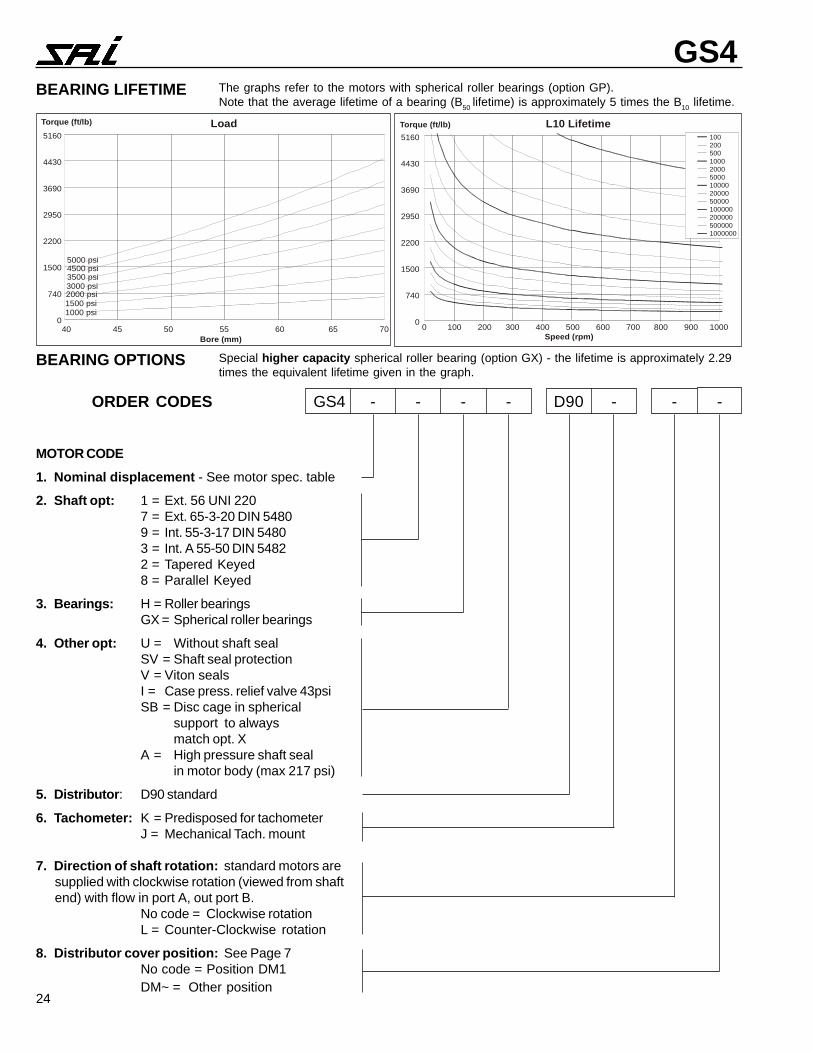
MOTOR CODE1. Nominal displacement - See motor spec. table
2. Shaft opt: 1 = Ext. 56 UNI 2207 = Ext. 65-3-20 DIN 54809 = Int. 55-3-17 DIN 54803 = Int. A 55-50 DIN 54822 = Tapered Keyed8 = Parallel Keyed
3. Bearings: H = Roller bearingsGX = Spherical roller bearings
4. Other opt: U = Without shaft sealSV = Shaft seal protectionV = Viton sealsI = Case press. relief valve 43psiSB = Disc cage in spherical
support to alwaysmatch opt. X
A = High pressure shaft sealin motor body (max 217 psi)
5. Distributor: D90 standard
6. Tachometer: K = Predisposed for tachometerJ = Mechanical Tach. mount
7. Direction of shaft rotation: standard motors aresupplied with clockwise rotation (viewed from shaftend) with flow in port A, out port B.
No code = Clockwise rotationL = Counter-Clockwise rotation
8. Distributor cover position: See Page 7No code = Position DM1DM~ = Other position
ORDER CODES GS4 - - - - D90 - - -
The graphs refer to the motors with spherical roller bearings (option GP).Note that the average lifetime of a bearing (B50 lifetime) is approximately 5 times the B10 lifetime.
BEARING LIFETIME
Special higher capacity spherical roller bearing (option GX) - the lifetime is approximately 2.29times the equivalent lifetime given in the graph.
BEARING OPTIONS
1002005001000200050001000020000500001000002000005000001000000
LoadTorque (ft/lb)
Bore (mm)
5000 psi4500 psi3500 psi3000 psi2000 psi1500 psi1000 psi
40 45 50 55 60 65 70
5160
4430
3690
2950
2200
1500
740
00 100 200 300 400 500 600 700 800 900 1000
Speed (rpm)
Torque (ft/lb) L10 Lifetime5160
4430
3690
2950
2200
1500
740
0
1002005001000200050001000020000500001000002000005000001000000
25
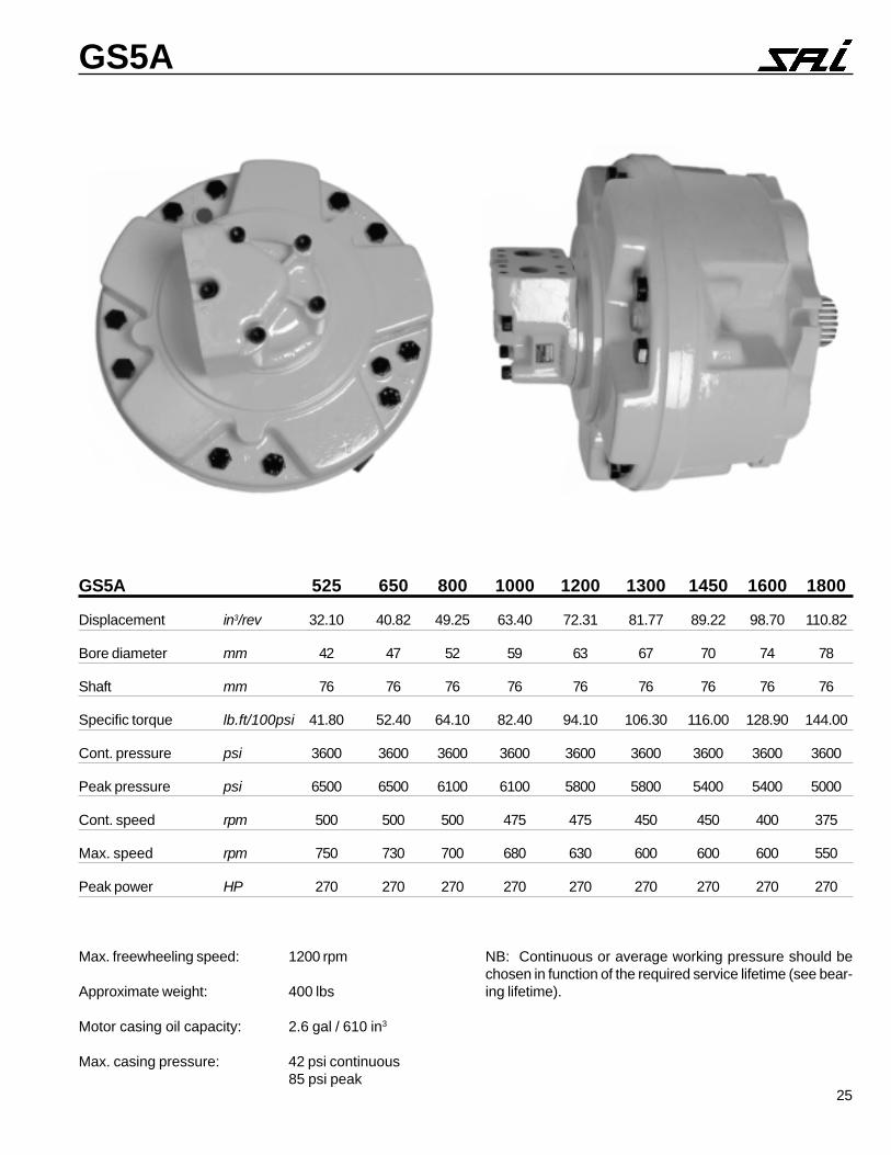
GS5A
Max. freewheeling speed: 1200 rpm
Approximate weight: 400 lbs
Motor casing oil capacity: 2.6 gal / 610 in3
Max. casing pressure: 42 psi continuous85 psi peak
NB: Continuous or average working pressure should bechosen in function of the required service lifetime (see bear-ing lifetime).
GS5A 525 650 800 1000 1200 1300 1450 1600 1800
Displacement in3/rev 32.10 40.82 49.25 63.40 72.31 81.77 89.22 98.70 110.82
Bore diameter mm 42 47 52 59 63 67 70 74 78
Shaft mm 76 76 76 76 76 76 76 76 76
Specific torque lb.ft/100psi 41.80 52.40 64.10 82.40 94.10 106.30 116.00 128.90 144.00
Cont. pressure psi 3600 3600 3600 3600 3600 3600 3600 3600 3600
Peak pressure psi 6500 6500 6100 6100 5800 5800 5400 5400 5000
Cont. speed rpm 500 500 500 475 475 450 450 400 375
Max. speed rpm 750 730 700 680 630 600 600 600 550
Peak power HP 270 270 270 270 270 270 270 270 270

26
GS5ADIMENSIONS
SHAFT OPTIONSSplined DIN 5480 7
UNI 221 1Tapered 2 Parallel Keyed 8 Internal DIN 5480 9
Spline DIN 5482 3
SPLINE DATA (dimensions in mm [1 in = 25.4 mm]) ADAPTORNID
0845NID02-3-56 2845NID62-2-55 0845NID71-3-55 122INU65
0d 0.06Ø 0.25Ø 0.15Ø 1d 0.65Ø 030.0+0+ 7H
1d 0.56Ø 047.0+0+ 41H 0.55Ø 0030+
0+ 21H 0.55Ø 047.0+0+ 41H 2d 0.56Ø 091.0+
0+ 11H
2d 0.95Ø 091.0+0+ 11H 0.05Ø 061.0+
0+ 11H 0.94Ø 061.0+0+ 11H A 0.01 820.0+
310.0+ 7F
A 52.5Ø 5.3Ø 52.5Ø 3d 0.65Ø 010.0-920.0- 6g
INU ad 101.45Ø 091.0+0+ 11H 209.64Ø 001.0+
0+ 01H 708.34Ø 061.0+0+ 11H 4d 0.56Ø 001.0-
092.0- 11d
3d 4.46Ø 0-091.0- 11h 5.45Ø 0-
091.0- 11h 4.45Ø 0-091.0- 11h B 0.01 310.0-
820.0- 7f
4d 4.85Ø 0-047.0- 41h 0.94Ø 0-
003.0- 21h 4.84Ø 0-026.0- 41h
B 0.6Ø 5.3Ø 0.6Ø
bd 999.07Ø 030.0-670.0- 8f 359.65Ø 060.0-
431.0- 9e 378.06Ø 030.0-670.0- 8f
27
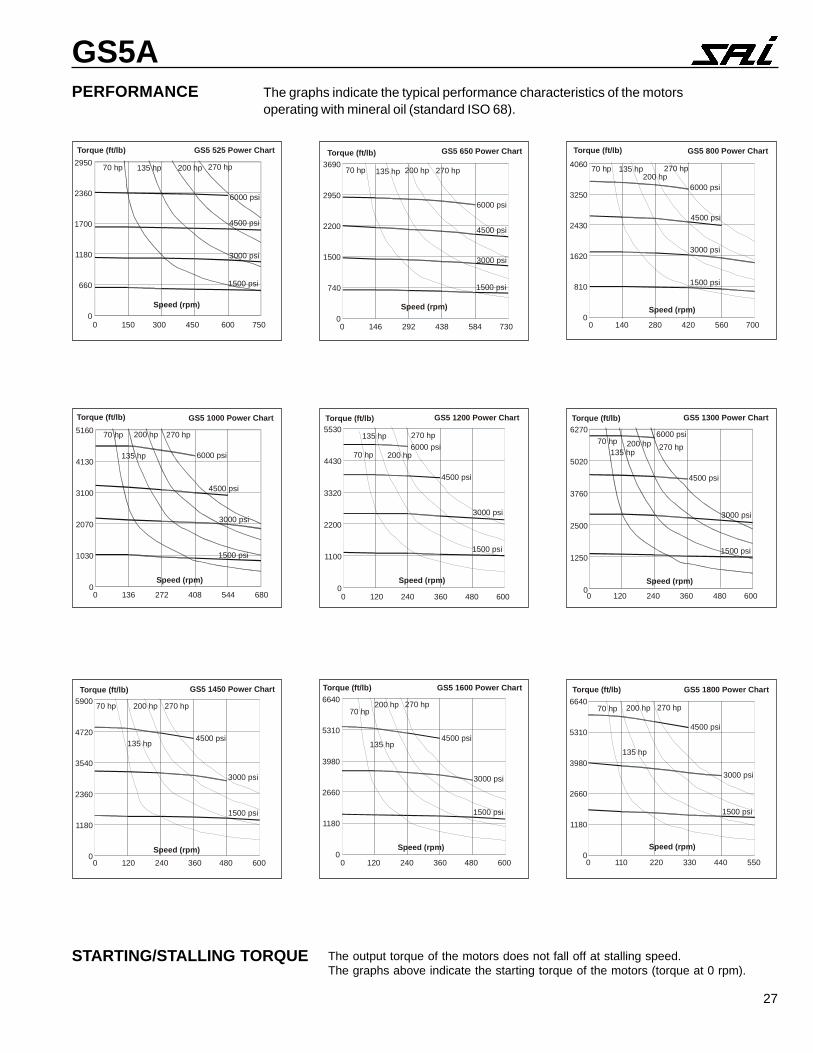
GS5APERFORMANCE The graphs indicate the typical performance characteristics of the motors
operating with mineral oil (standard ISO 68).
STARTING/STALLING TORQUE The output torque of the motors does not fall off at stalling speed.The graphs above indicate the starting torque of the motors (torque at 0 rpm).
GS5 525 Power ChartTorque (ft/lb)
Speed (rpm)
70 hp 135 hp 200 hp 270 hp
6000 psi
4500 psi
3000 psi
1500 psi
0 150 300 450 600 750
2950
2360
1700
1180
660
0
GS5 650 Power ChartTorque (ft/lb)
Speed (rpm)
70 hp 135 hp 200 hp 270 hp
6000 psi
4500 psi
3000 psi
1500 psi
0 146 292 438 584 730
3690
2950
2200
1500
740
0
GS5 800 Power ChartTorque (ft/lb)
Speed (rpm)
6000 psi
4500 psi
3000 psi
1500 psi
70 hp 135 hp200 hp
270 hp
0 140 280 420 560 700
4060
3250
2430
1620
810
0
GS5 1000 Power ChartTorque (ft/lb)
Speed (rpm)
70 hp
135 hp
200 hp 270 hp
6000 psi
4500 psi
3000 psi
1500 psi
0 136 272 408 544 680
5160
4130
3100
2070
1030
0
GS5 1200 Power ChartTorque (ft/lb)
Speed (rpm)
70 hp
135 hp
200 hp
270 hp6000 psi
4500 psi
3000 psi
1500 psi
0 120 240 360 480 600
5530
4430
3320
2200
1100
0
GS5 1300 Power ChartTorque (ft/lb)
Speed (rpm)
70 hp135 hp
200 hp 270 hp6000 psi
4500 psi
3000 psi
1500 psi
0 120 240 360 480 600
6270
5020
3760
2500
1250
0
GS5 1450 Power ChartTorque (ft/lb)
Speed (rpm)
70 hp
135 hp
200 hp 270 hp
4500 psi
3000 psi
1500 psi
0 120 240 360 480 600
5900
4720
3540
2360
1180
0
GS5 1600 Power ChartTorque (ft/lb)
Speed (rpm)
70 hp
135 hp
200 hp 270 hp
4500 psi
3000 psi
1500 psi
0 120 240 360 480 600
6640
5310
3980
2660
1180
0
GS5 1800 Power ChartTorque (ft/lb)
Speed (rpm)
70 hp
135 hp
200 hp 270 hp
4500 psi
3000 psi
1500 psi
0 110 220 330 440 550
6640
5310
3980
2660
1180
0
28
GS5A
LoadTorque (ft/lb)
Bore (mm)
Torque (ft/lb) L10 Lifetime
Speed (rpm)42 46 50 54 58 62 66 70 74 78 0 200 400 600 800 1000
7380
6640
5900
5160
4430
3690
2950
2200
1500
740
0
7380
6640
5900
5160
4430
3690
2950
2200
1500
740
0
1002005001000200050001000020000500001000002000005000001000000
MOTOR CODE
1. Nominal displacement - See motor spec. table
2. Shaft opt: 1 = Ext. 56 UNI 2217 = Ext. 65-3-20 DIN 54809 = Int. 55-3-17 DIN 54803 = Int. 55-50 DIN 54822 = Tapered Keyed8 = Parallel Keyed
3. Bearings: No code = Roller bearingsGX =Spher. roller bearings high cap.
4. Other opt: U = Without shaft sealSV = Shaft seal protectionVY = Viton sealsI = Case press. relief valve 43psiSB = Disc cage in spher support to
always match opt. X
5. Distributor: D90 standard
6. Tachometer: K = Predisposed for tachometerJ = with tach. coupling
7. Direction of shaft rotation: standard motors aresupplied with clockwise rotation (viewed from shaftend) with flow in port A, out port B.
No code = Clockwise rotationL = Counter-Clockwise rotation
8. Distributor cover position: See Page 7No code = Position DM1DM~ = Other position
ORDER CODES GM5A - - - - D90 - - -
The graphs refer to the motors with spherical roller bearings (option G).Note that the average lifetime of a bearing (B50 lifetime) is approximately 5 times the B10 lifetime.
BEARING LIFETIME
Special higher capacity spherical roller bearing (option GX) - the lifetime is approximately 2.29times the equivalent lifetime given in the graph.
BEARING OPTIONS
29
GS6
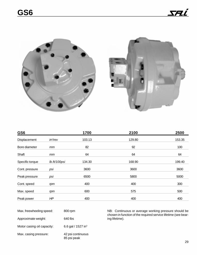
Max. freewheeling speed: 800 rpm
Approximate weight: 640 lbs
Motor casing oil capacity: 6.6 gal / 1527 in3
Max. casing pressure: 42 psi continuous85 psi peak
NB: Continuous or average working pressure should bechosen in function of the required service lifetime (see bear-ing lifetime).
GS6 1700 2100 2500Displacement in3/rev 103.13 129.80 153.35
Bore diameter mm 82 92 100
Shaft mm 64 64 64
Specific torque lb.ft/100psi 134.30 168.90 199.40
Cont. pressure psi 3600 3600 3600
Peak pressure psi 6500 5800 5000
Cont. speed rpm 400 400 300
Max. speed rpm 600 575 500
Peak power HP 400 400 400
30
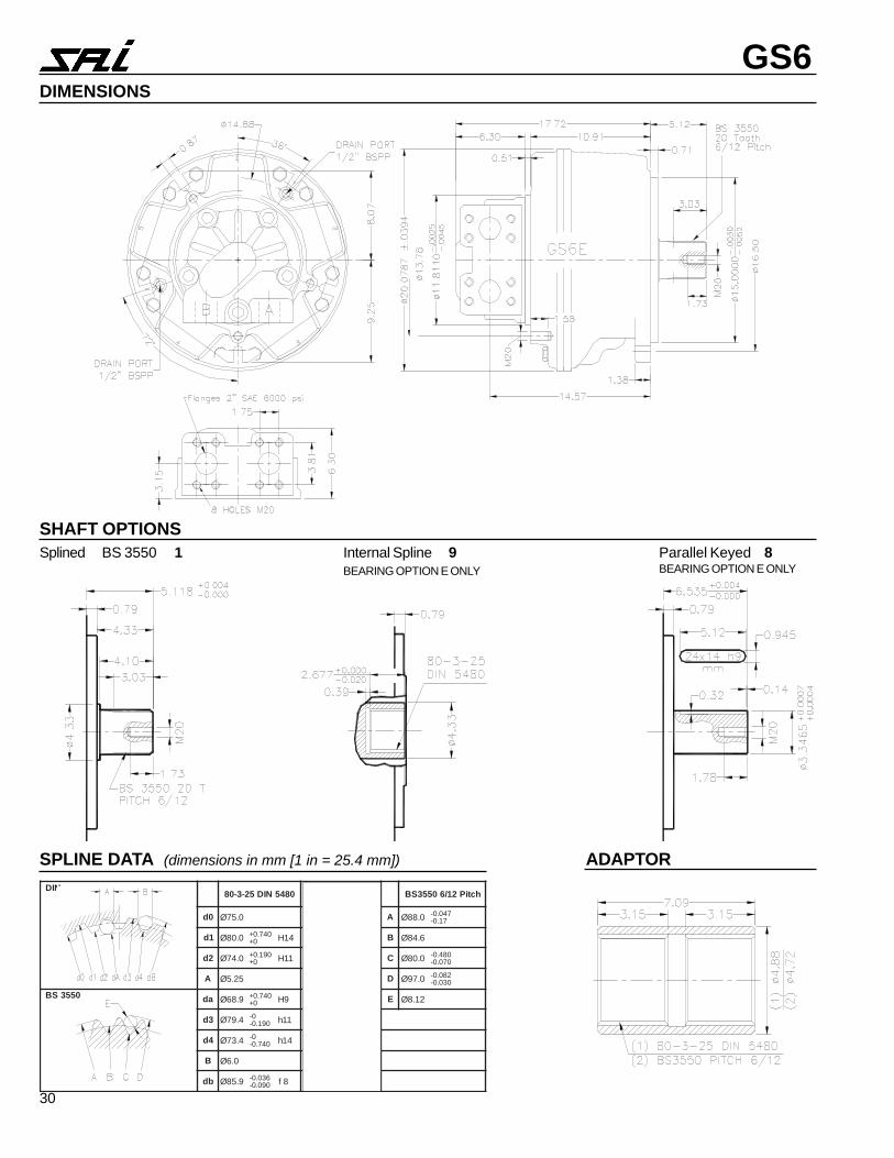
GS6DIMENSIONS
SPLINE DATA (dimensions in mm [1 in = 25.4 mm]) ADAPTOR
SHAFT OPTIONSSplined BS 3550 1 Parallel Keyed 8
BEARING OPTION E ONLYInternal Spline 9BEARING OPTION E ONLY
NID0845NID52-3-08 0845NID02-3-56 hctiP21/60553SB
0d 0.57Ø 0.06Ø A 0.88Ø 740.0-71.0-
1d 0.08Ø 047.0+0+ 41H 0.56Ø 047.0+
0+ 41H B 6.48Ø
2d 0.47Ø 091.0+0+ 11H 0.95Ø 091.0+
0+ 11H C 0.08Ø 084.0-070.0-
A 52.5Ø 52.5Ø D 0.79Ø 280.0-030.0-
0553SB ad 9.86Ø 047.0+0+ 9H 1.45Ø 091.0+
0+ 11H E 21.8Ø
3d 4.97Ø 0-091.0- 11h 4.46Ø 0-
091.0- 11h
4d 4.37Ø 0-047.0- 41h 4.85Ø 0-
047.0- 41h
B 0.6Ø 0.6Ø
bd 9.58Ø 630.0-090.0- 8f 9.07Ø 030.0-
670.0- 8f

31
GS6PERFORMANCE The graphs indicate the typical performance characteristics of the motors
operating with mineral oil (standard ISO 68).
STARTING/STALLING TORQUE The output torque of the motors does not fall off at stalling speed.The graphs above indicate the starting torque of the motors (torque at 0 rpm).
The graphs refer to the motors with spherical roller bearings (option G).Note that the average lifetime of a bearing (B50 lifetime) is approximately 5 times the B10 lifetime.
BEARING LIFETIME
Special higher capacity spherical roller bearing (on request) - the lifetime is approximately 1.6times the equivalent lifetime given in the graph.
BEARING OPTIONS
Motor Displacement
Pres
sure
(psi
)
1700
2100
2500
5000450035003000200015001000
70 80 90 100 110Piston Diameter (mm)
B10 LifetimeHours
Shaft Speed (rpm)0 50 100 150 200 250 300 350 400
100
200
5001,0002,0005,00010,000100,0001,000,000
GS6 1700 Power ChartTorque (ft/lb)
Speed (rpm)
100 hp
200 hp
300 hp 400 hp
6000 psi
4500 psi
3000 psi
1500 psi
0 120 240 360 480 600
9590
7670
5750
3840
1920
0
GS6 2100 Power ChartTorque (ft/lb)
Speed (rpm)
100 hp200 hp
300 hp400 hp
6000 psi
4500 psi
3000 psi
1500 psi
0 115 230 345 460 575
9220
7380
5530
3690
1850
0
GS6 2500 Power ChartTorque (ft/lb)
Speed (rpm)
100 hp200 hp
300 hp400 hp
4500 psi
3000 psi
1500 psi
0 100 200 300 400 500
10330
8260
6200
4130
2070
0
32
GS6
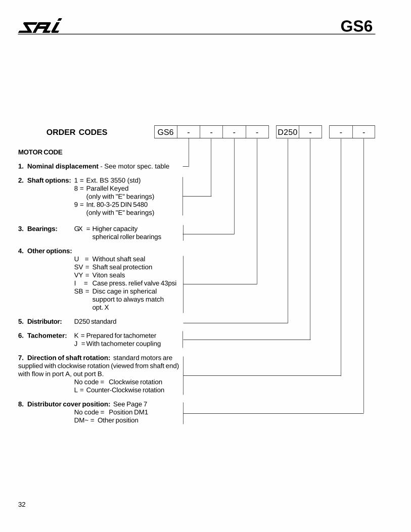
MOTOR CODE
1. Nominal displacement - See motor spec. table
2. Shaft options: 1 = Ext. BS 3550 (std)8 = Parallel Keyed
(only with "E" bearings)9 = Int. 80-3-25 DIN 5480
(only with "E" bearings)
3. Bearings: GX = Higher capacityspherical roller bearings
4. Other options:U = Without shaft sealSV = Shaft seal protectionVY = Viton sealsI = Case press. relief valve 43psiSB = Disc cage in spherical
support to always matchopt. X
5. Distributor: D250 standard
6. Tachometer: K = Prepared for tachometerJ = With tachometer coupling
7. Direction of shaft rotation: standard motors aresupplied with clockwise rotation (viewed from shaft end)with flow in port A, out port B.
No code = Clockwise rotationL = Counter-Clockwise rotation
8. Distributor cover position: See Page 7No code = Position DM1DM~ = Other position
ORDER CODES GS6 - - - - D250 - - -

SAI Hydraulics, Inc.3905 W. 9th StreetTrainer, PA 19061(610) 497-0190 Fax (610) 497-0194
SAI Hydraulics Canada Ltd.6105 Boulevard CoutureSt. Leonard, PQ H 1P3G7(514) 323-4552 Fax (514) 323-8780
WORLDWIDE