safespot integrated project - ist-4-026963-ip … · vanet rs232 ethernet mainpc ethernet switch...
TRANSCRIPT

Deliverable N. D4.4.4 Dissemination Level (PU) Copyright SAFESPOT
Contract N. IST-4-026963-IP
SF_D4.4.4_Equipped_Motorcycle_Integrating_SMA_v0.9. doc Page 1 of 20 SCOVA
SAFESPOT INTEGRATED PROJECT - IST-4-026963-IP
DELIVERABLE 4.4.4
SP4 – SCOVA – Cooperative Systems Applications
Vehicle Based
Deliverable No. (use the number indicated on technical annex)
D4.4.4
SubProject No. SP4 SubProject Title SCOVA
Workpackage No. WP4 Workpackage Title Implementation and Prototypes
Task No. T4.4.3; T4.4.4
Task Title Integration of the SAFESPOT applications in equipped vehicles; SAFESPOT application: system tuning and re-adjustment
Authors (per company, if more than one company provide it together)
Paolo Cravini - Piaggio & C. S.p.a. Vincenzo Manzoni & Andrea Corti – Politecnico di Mi lano
Status (F: final; D: draft; RD: revised draft):
F
Version No: 0.9
File Name: SF_D4.4.4_Equipped_Motorcycle_Integrating_SMA_v0.7. doc
Planned Date of submission according to TA:
30/04/2009
Issue Date: 09/04/2009
Project start date and duration 01 February 2006, 48 Months
Equipped Motorcycles Integrating the Safety Margin Applications

Deliverable N. D4.4.4 Dissemination Level (PU) Copyright SAFESPOT
Contract N. IST-4-026963-IP
SF_D4.4.4_Equipped_Motorcycle_Integrating_SMA_v0.9. doc Page 2 of 20 SCOVA
Revision Log
Version Date Reason Name and Company
0.1 23/03/2009 First draft released
Paolo Cravini – Piaggio Vincenzo Manzoni & Andrea Corti – Politecnico Milano
0.2 24/03/2009 Overall peer reading Giulio Vivo - CRF
0.3 30/03/2009 Second draft released
Paolo Cravini – Piaggio Vincenzo Manzoni & Andrea Corti – Politecnico Milano
0.4 02/04/2009 Further minor corrections Giulio Vivo - CRF
0.5 07/04/2009 Final revision
Paolo Cravini – Piaggio Vincenzo Manzoni & Andrea Corti – Politecnico Milano
0.6 09/04/2010 Updating after Amsterdam Showcase 2010
Paolo Cravini – Piaggio Vincenzo Manzoni & Andrea Corti – Politecnico Milano
0.7 10/04/2010 Final minor corrections
Paolo Cravini – Piaggio Vincenzo Manzoni & Andrea Corti – Politecnico Milano
0.8 16/04/2010 Added few further pictures related to the Amsterdam Showcase 2010
Giulio Vivo – CRF Paolo Cravini – Piaggio Vincenzo Manzoni & Andrea Corti – Politecnico Milano
0.9 21/04/2010
Added links to the Stockholm and Amsterdam demonstrations, added a dedicate subchapter of 1.3
Giulio Vivo – CRF Paolo Cravini, Marco Pieve – Piaggio

Deliverable N. D4.4.4 Dissemination Level (PU) Copyright SAFESPOT
Contract N. IST-4-026963-IP
SF_D4.4.4_Equipped_Motorcycle_Integrating_SMA_v0.9. doc Page 3 of 20 SCOVA
Abbreviation List BT Bluetooth
CAD Computer Aided Design
CAN Controller Area Network
COSSIB Cooperative Safety Systems Infrastructure Based
CVIS Cooperative Vehicle-Infrastructure System
ECU Electronic Control Unit
ExtMsgApp External Message Application
GPS Global Positioning System
HMI Human Machine Interface
LAN Local Area Network
LCM Lane Change Manoeuvre
PTW Powered Two Wheelers
RS232 EIA Recommended Standard 232
SAFEPROBE In-Vehicle Sensing and Platform
SCOVA System Cooperative Vehicle Based Application
SO Safe Overtaking
SP Sub Project
TS Test Site
UDP User Datagram Protocol
VANET Vehicle Ad Hoc Network

Deliverable N. D4.4.4 Dissemination Level (PU) Copyright SAFESPOT
Contract N. IST-4-026963-IP
SF_D4.4.4_Equipped_Motorcycle_Integrating_SMA_v0.9. doc Page 4 of 20 SCOVA
Table of contents Revision Log .............................................................................................................................................2 Abbreviation List .......................................................................................................................................3 Table of contents ......................................................................................................................................4 List of Figures ...........................................................................................................................................4 List of Tables.............................................................................................................................................4 EXECUTIVE SUMMARY ..........................................................................................................................5 1. Demonstrator vehicles provided by PIAGGIO...................................................................................6
1.1. Vehicles .................................................................................................................................6 1.2. Equipment..............................................................................................................................7
1.2.1. Hardware architecture.......................................................................................................7 1.2.2. Gateway ............................................................................................................................9 1.2.3. Positioning.......................................................................................................................10 1.2.4. VANET ............................................................................................................................11 1.2.5. PTW ECUs......................................................................................................................11 1.2.6. Human Machine Interface ...............................................................................................11 1.2.6.1 Human Machine Interface “Updating after the Amsterdam Showcase 2010”..................12 1.2.7. Functionalities .................................................................................................................13
1.3. Applications..........................................................................................................................14 1.3.1. Executed demonstration activities...................................................................................16
Conclusions ............................................................................................................................................20 2. References......................................................................................................................................20
List of Figures Figure 1: PIAGGIO MP3 250cc (on the road & CAD drawing)...................................................6 Figure 2: Scheme of the hardware architecture (PIAGGIO demonstrators) ..............................7 Figure 3: Physical location of subsystems (PIAGGIO demonstrators).......................................8 Figure 4: PTW Gateway .............................................................................................................9 Figure 5: Positioning system ....................................................................................................10 Figure 6: HMI of Piaggio Demonstrator – LCD screen.............................................................11 Figure 7: HMI of Piaggio Demonstrator – Bluetooth helmet.....................................................12 Figure 8: Software functionalities (PIAGGIO demonstrators)...................................................13 Figure 9: Lane Change Manoeuvre – General Use Case........................................................15 Figure 10: Safe Overtaking – General Use Case.....................................................................15 Figure 11: ITS Stockholm event – Preparation of the Use Case to demonstrate ....................16 Figure 12: ITS Stockholm event – Execution of the Use Case ................................................16 Figure 11: Cooperative Mobility Showcase 2010 - One guest is instructed about the usage of the Bluetooth helmet.................................................................................................................17 Figure 12: Cooperative Mobility Showcase 2010 - One guest is helped to dress the Bluetooth helmet .......................................................................................................................................17 Figure 13: Cooperative Mobility Showcase 2010 - One guest is ready to take place on the Piaggio PTW vehicle.................................................................................................................18 Figure 14: Cooperative Mobility Showcase 2010 - Preparation phase of the demonstrated manoeuvres (1/2)......................................................................................................................18 Figure 15: Cooperative Mobility Showcase 2010 - Preparation phase of the demonstrated manoeuvres (2/2)......................................................................................................................19 Figure 16: Cooperative Mobility Showcase 2010 - Manoeuvre in the Area #1 during the Amsterdam Showcase 2010 (1/2) ............................................................................................19 Figure 17: Cooperative Mobility Showcase 2010 - Manoeuvre in the Area #1 during the Amsterdam Showcase 2010 (2/2) ............................................................................................19
List of Tables Table 1: SCOVA applications ...................................................................................................14
Deliverable N. D4.4.4 Dissemination Level (PU) Copyright SAFESPOT
Contract N. IST-4-026963-IP
SF_D4.4.4_Equipped_Motorcycle_Integrating_SMA_v0.9. doc Page 5 of 20 SCOVA
EXECUTIVE SUMMARY In this document the implementation of the hardware architecture compliant to the SAFESPOT system in a Powered Two Wheelers (PTW) is presented. The SAFESPOT system adopts vehicle to vehicle and vehicle to infrastructure communication in order to demonstrate significant benefits in the driving safety. Since the PTW belong to the class of the vulnerable road users, the described implementation addresses these high level objectives directly, turning out as an achievement of high relevance for the overall integrated project.
The present document is an accompanying report of D eliverable D4.4.4 (which consists of equipped motorcycle demonstrator s). It gives a summary of the on-board prototype systems and functions supporting the vehicle based Safety Margin applications. The demonstration of these applications forms part of the Test Site activities running in the final year of the SAFESPOT project.
The present report is organized as follows:
• Description, from the technical point of view, of the vehicle that has been chosen as PTW;
• Presentation of the architecture customized for it;
• Selected application developed for the PTW platform.
It is also shortly illustrated how the vehicles are equipped. The most part of the components and sub-systems, with a specific focus on the technology platform developed by SP1-SAFEPROBE, have been detailed in deliverable D1.4.2 – “HW and SW specifications of prototype and test bed components” [1] and in deliverable D1.4.5 – “Probe vehicles prototypes” [2].

Deliverable N. D4.4.4 Dissemination Level (PU) Copyright SAFESPOT
Contract N. IST-4-026963-IP
SF_D4.4.4_Equipped_Motorcycle_Integrating_SMA_v0.9. doc Page 6 of 20 SCOVA
1. Demonstrator vehicles provided by PIAGGIO
1.1. Vehicles Piaggio & C. S.p.a. is in charge to provide the PTWs for the SAFESPOT project. The system is implemented in two normal production scooters: MP3 250. The vehicles, tilting three-wheeled scooters available on the market since 2006, are based on a monocylindrique 250cc 4stroke engine, continuous variable transmission, water cooled, fuel electronic injection (Figure 1).
MP3 scooter has two front wheels and one rear. The model has been chosen primarily as an innovative Piaggio scooter whose characteristics guarantee an increase in the safety performances of the vehicle due to an increased stability. In addition, the MP3 has a representative and up to date electrical and electronic architecture, suitable for the integration of new features of SAFESPOT system.
Figure 1: PIAGGIO MP3 250cc (on the road & CAD draw ing)

Deliverable N. D4.4.4 Dissemination Level (PU) Copyright SAFESPOT
Contract N. IST-4-026963-IP
SF_D4.4.4_Equipped_Motorcycle_Integrating_SMA_v0.9. doc Page 7 of 20 SCOVA
1.2. Equipment
The Piaggio PTW presents unique challenges for SAFESPOT. The space available for hardware is clearly limited (65 dm3 of under-seat capacity), as is the electrical power availability. In fact, because of these constraints no environmental perception systems have been adopted. A minimal system configuration consists of a gateway, a VANET Router, a Main PC and a GPS module.
1.2.1. Hardware architecture
Several modifications and adaptations have been necessary in order to equip the vehicles with the devices required for the SAFESPOT applications to be implemented and demonstrated. Figure 2 presents the components and the high level interconnections of the hardware architecture for the PTW demonstrators.
Figure 2: Scheme of the hardware architecture (PIAG GIO demonstrators)
The scheme depicted in the above figure indicates the main system components: the various processing units, the networking interconnections and in particular the dual frequency GPS with Omnistar correction. This last device is necessary in order to improve the accuracy of positioning (up to the target of 0.20 meters) as in Piaggio demonstrators no videocamera or laser scanner are installed to support a standard GPS in order to reach the SAFESPOT requirements in terms of position accuracy.
Power supply of the demonstrator is a lead battery of “12V-12Ah”, so for the SAFESPOT systems two DC-DC converters are needed: a “12v to 5v” and a “12v to 7.5v”.
CAN Analog
Sensors
VANET router
rs232
Ethernet
MainPC
Ethernet switch
rs232-ethernet converter Dual frequency GPS + Omnistar
Bosch Inertial Platform
To HMI
Bluetooth Helmet
LCD screen
GATEWAY
Deliverable N. D4.4.4 Dissemination Level (PU) Copyright SAFESPOT
Contract N. IST-4-026963-IP
SF_D4.4.4_Equipped_Motorcycle_Integrating_SMA_v0.9. doc Page 8 of 20 SCOVA
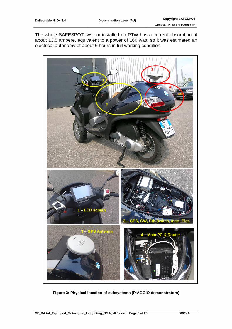
The whole SAFESPOT system installed on PTW has a current absorption of about 13.5 ampere, equivalent to a power of 160 watt: so it was estimated an electrical autonomy of about 6 hours in full working condition.
Figure 3: Physical location of subsystems (PIAGGIO demonstrators)
1
2
3
4
1 – LCD screen
2 – GPS, GW, Eth.Switch, Inert. Plat.
3 – GPS Antenna 4 – Main PC & Router

Deliverable N. D4.4.4 Dissemination Level (PU) Copyright SAFESPOT
Contract N. IST-4-026963-IP
SF_D4.4.4_Equipped_Motorcycle_Integrating_SMA_v0.9. doc Page 9 of 20 SCOVA
1.2.2. Gateway
Piaggio MP3 provides the information about speed, throttle opening percentage and engine speed via CAN bus. Other important signals are not present on the CAN network, like direction indicator and braking, but the acquisition of these signals has been obtained in analogic way.
Piaggio’s gateway is composed by two different components:
1. an ECU (Aprilia racing APX device) which is adopted to collect the information from analogic sensors and from CAN bus and to send them to a serial line.
2. a serial-to-Ethernet converter to translate the data into UDP messages and to timestamp them.
Figure 4: PTW Gateway
The APX ECU collects data from the PTW electronic control unit, both through CAN-bus and analogic signals. In particular the CAN digital network conveys data on engine speed, vehicle speed, throttle opening percentage; in addition, a Bosch inertial platform provides on the same network information on yaw rate, roll rate, lateral acceleration and longitudinal acceleration. Signals related to direction indication lights, braking and tilt sensor are acquired in a analogic form. The data acquired by the APX ECU are then sent on a RS232 serial line to the SS100 device, which is a full-duplex converter based on a Linux embedded system. This unit is in charge of time stamping the data coming from the APX ECU, creating SAFESPOT compliant UDP datagrams (as described in the official SP7 protocol specifications D7.3.1 Annex1 - SAFESPOT data format and messages [3]) and sending them on the Ethernet LAN. The timestamp, which is a critical function, is based on a NTP client, whose time server runs on the Main PC.
rs232-ethernet converter
rs232
GATEWAY
Vehicle CAN (engine speed, vehicle speed, throttle opening %)
Analog Sensor (direction indicators, braking, tilt)
Inertial Platform (yaw rate, roll rate, lateral acc., longitudinal acc.)

Deliverable N. D4.4.4 Dissemination Level (PU) Copyright SAFESPOT
Contract N. IST-4-026963-IP
SF_D4.4.4_Equipped_Motorcycle_Integrating_SMA_v0.9. doc Page 10 of 20 SCOVA
1.2.3. Positioning
The precision of a standard GPS is not sufficient to estimate a position with accuracy less than 1.5 m, the half of a width of a road lane. For the vehicles, in the reference SAFESPOT implementation, the positioning precision is increased by means of a landmark detection camera. This solution is incompatible with the Piaggio MP3 vehicles for two reasons: the first is that physical constraints such as dimensions and weight are exceeding the vehicle capacity and loading specifications (MP3 is a rolling vehicle); the second is a consequence of the significant rolling angles that are reached by the MP3 during the normal driving conditions. These angles imply that the video and data processing algorithms to interpreter in real time the inertial information must be very complex.
The adopted solution for the positioning system is based on a dual frequency GPS with Omnistar correction. A dedicated Ethernet “sniffer” program was developed to convey the positioning information to the TeleAtlas/Navteq LDM. The positioning software, in the PTW implementation, is included in the Main PC. The inertial platform is linked to the GPS receiver to improve the estimation and to support it in case of temporary lack of signal. The GPS device is linked to the Main PC (see Figure 5) and provides an estimation of the absolute position with a frequency of 20 Hz.
Figure 5: Positioning system

Deliverable N. D4.4.4 Dissemination Level (PU) Copyright SAFESPOT
Contract N. IST-4-026963-IP
SF_D4.4.4_Equipped_Motorcycle_Integrating_SMA_v0.9. doc Page 11 of 20 SCOVA
1.2.4. VANET
The SAFESPOT VANET router is based on a Single Board Computer (compact PC) unit. In particular, it has been chosen a pre-assembled Car PC, equipped with one Ethernet port and one miniPCI port. This last port is used to attach the QFree card, providing the wireless connection capabilities.
The VANET router is connected with all of other devices belonging to the SAFESPOT architecture by means of an Ethernet switch. The wireless interface is compliant with the standard IEEE 802.11p and it transmits in the reserved band 5.895-5.905 GHz.
The software installed on the router is a Linux distribution with a 2.6.x or higher as operating system.
1.2.5. PTW ECUs
In the SAFESPOT reference architecture there are three PCs: the Main PC, the Positioning PC and the Application PC. The task carried out by these PCs is, respectively, to host the local dynamic map, to estimate the position and to host the application where the SP4 applicative tasks (scenario analysis and drivers assistance applications, for instance) are running. Clearly, the space available in the travelling case of the PTW is limited, as it is the battery capacity, and these constraints are incompatible with the usage of three PCs. So, it has been decided to concentrate all the needed functionalities into a single unit, the Main PC.
1.2.6. Human Machine Interface
The results of the analysis in the form of warning messages are delivered to the driver using a human machine interface. In order to minimize the number of devices mounted on the vehicle, the adopted solution has been a touch screen, combining a display and an interaction system.
Figure 6: HMI of Piaggio Demonstrator – LCD screen
LCD screen installed on the PTW

Deliverable N. D4.4.4 Dissemination Level (PU) Copyright SAFESPOT
Contract N. IST-4-026963-IP
SF_D4.4.4_Equipped_Motorcycle_Integrating_SMA_v0.9. doc Page 12 of 20 SCOVA
1.2.6.1 Human Machine Interface “Updating after the Amsterdam Showcase 2010”
In many dangerous situations, there are practical evidences that only the video feedback is not safe and reliable to warn the driver. For this reason the main PC of the PTW has been equipped with a Bluetooth communication system which is used to send audio warnings into the rider’s BT helmet.
Figure 7: HMI of Piaggio Demonstrator – Bluetooth h elmet
“A vehicle is approaching from the behind”

Deliverable N. D4.4.4 Dissemination Level (PU) Copyright SAFESPOT
Contract N. IST-4-026963-IP
SF_D4.4.4_Equipped_Motorcycle_Integrating_SMA_v0.9. doc Page 13 of 20 SCOVA
1.2.7. Functionalities
According to the components description, the architecture was chosen and developed in order to facilitate the prototyping of the system. The final implementation is designed around an Ethernet LAN of PCs. At the end of the requirement analysis process, it has been acknowledged the need to obtain:
• a detailed description of the vehicle in term of sampled signals which give a measure of static and dynamic variables;
• a very precise estimation of the absolute position of the vehicle; • an absolute and shared timestamp representing the time of the
measurements; • a communication system allowing to share data between vehicle and
infrastructure unit; • an LDM database where to store all of the information collected; • an LDM database where the stored information are periodically
evaluated by the SAFESPOT applications which analyze the scenario surrounding the PTW, accordingly with the SP4-SCOVA specifications;
• a human-machine interface.
Figure 8: Software functionalities (PIAGGIO demonst rators)
Vehicle sensors (GW)
Positioning (GPS/Qfree)
V2V/V2I communication (VANET)
Data fusion & LDM
Application Manager
•App1: Lane Change Manoeuvre
•App2: Safe Overtaking
HMI
quer y infor mation
Interaction

Deliverable N. D4.4.4 Dissemination Level (PU) Copyright SAFESPOT
Contract N. IST-4-026963-IP
SF_D4.4.4_Equipped_Motorcycle_Integrating_SMA_v0.9. doc Page 14 of 20 SCOVA
1.3. Applications For the end user, the architecture described in the previous paragraph has to sustain the SP4 applicative tasks, where information stored in the LDM is analysed and the resulting possible warnings should be presented to the driver. These applicative tasks are running with a tuneable frequency (currently 12.5 Hz). In the present section the SP4-SCOVA applications running on the Piaggio PTW are shortly summarized, together with the method - based on Use Cases – adopted to build up behavioral and functional descriptions of such applications.
In total, within SP4-SCOVA, ten applications, grouped in four clusters are developed by a team of companies, led by “Application Leaders” – as pointed out in red in the table below.
Table 1: SCOVA applications
In the Piaggio MP3 demonstrators, the functionalities needed to host and to demonstrate the following SP4 applications are considered:
• LCM – Lane Change Manoeuvre • SO – Safe Overtaking
For both LCM and SO applications, PIAGGIO has the direct responsibility of defining the whole chain of development, from the definition of the User Needs and Requirements, to the Specifications, to the Implementation, to the Evaluation to the Validation; in other terms, in the internal jargon of SP4, PIAGGIO is the Application Leader of the above applications.

Deliverable N. D4.4.4 Dissemination Level (PU) Copyright SAFESPOT
Contract N. IST-4-026963-IP
SF_D4.4.4_Equipped_Motorcycle_Integrating_SMA_v0.9. doc Page 15 of 20 SCOVA
For the Lane Change Manoeuvre , it is commonly evident that even if specific rear mirrors help drivers to have a good vision around the vehicle, some blind spot still exist in many situations. Especially for trucks and commercial vehicles it exist a relevant need of support for the lane change manoeuvre, in order to improve the driver information about the presence of other vehicles all around.
The General Use Case for the Lane Change Manoeuvre provides the driver’s assistance to prevent the lateral collisions in general scenarios, as showed in the pictogram below:
Figure 9: Lane Change Manoeuvre – General Use Case Safe Overtaking , in general, is a need for most drivers due to blinds spots and differential of speed between involved actors. The support provided by this application is related to the prevention of collision among vehicles in an overtaking situation (integration of blind spot and early notification to the preceding driver of the intention to overtake of the vehicle behind). The General Use Case for the Safe Overtaking describes the conditions to provide assistance to the ego vehicle drivers, in order to perform safe overtaking manoeuvres in general scenarios, like the one represented in the pictogram below:
Figure 10: Safe Overtaking – General Use Case
These applications have been initially introduced in D4.2.2 - Safety Margin concept [4] and in D4.2.3 - Use case and typical accident situation [5]; the related functional specifications have been detailed in D4.3.2 - SP4 Applications Functional Specifications [6].

Deliverable N. D4.4.4 Dissemination Level (PU) Copyright SAFESPOT
Contract N. IST-4-026963-IP
SF_D4.4.4_Equipped_Motorcycle_Integrating_SMA_v0.9. doc Page 16 of 20 SCOVA
1.3.1. Executed demonstration activities
Two relevant demonstration events happened in the last year of activity of the SAFESPOT project: the demonstration, during the 16th World Congress for ITS Systems and Services in Stockholm, on September 2009:
http://www.itsworldcongress.com/
and the demonstration during the Cooperative Mobility Showcase 2010 - smart vehicles on intelligent roads, held in Amsterdam, on March 2010:
http://www.cooperativemobilityshowcase.eu/nl/en/pages/default.aspx
Following pictures report some of the activities carried out during the above demonstration events.
Figure 11: ITS Stockholm event – Preparation of the Use Case to demonstrate
Figure 12: ITS Stockholm event – Execution of the U se Case

Deliverable N. D4.4.4 Dissemination Level (PU) Copyright SAFESPOT
Contract N. IST-4-026963-IP
SF_D4.4.4_Equipped_Motorcycle_Integrating_SMA_v0.9. doc Page 17 of 20 SCOVA
Figure 13: Cooperative Mobility Showcase 2010 - One guest is instructed about the
usage of the Bluetooth helmet
Figure 14: Cooperative Mobility Showcase 2010 - One guest is helped to dress the
Bluetooth helmet

Deliverable N. D4.4.4 Dissemination Level (PU) Copyright SAFESPOT
Contract N. IST-4-026963-IP
SF_D4.4.4_Equipped_Motorcycle_Integrating_SMA_v0.9. doc Page 18 of 20 SCOVA
Figure 15: Cooperative Mobility Showcase 2010 - One guest is ready to take place on the Piaggio PTW vehicle
Figure 16: Cooperative Mobility Showcase 2010 - Pre paration phase of the demonstrated manoeuvres (1/2)

Deliverable N. D4.4.4 Dissemination Level (PU) Copyright SAFESPOT
Contract N. IST-4-026963-IP
SF_D4.4.4_Equipped_Motorcycle_Integrating_SMA_v0.9. doc Page 19 of 20 SCOVA
Figure 17: Cooperative Mobility Showcase 2010 - Pre paration phase of the
demonstrated manoeuvres (2/2)
Figure 18: Cooperative Mobility Showcase 2010 - Man oeuvre in the Area #1 during the Amsterdam Showcase 2010 (1/2)
Figure 19: Cooperative Mobility Showcase 2010 - Man oeuvre in the Area #1 during the Amsterdam Showcase 2010 (2/2)

Deliverable N. D4.4.4 Dissemination Level (PU) Copyright SAFESPOT
Contract N. IST-4-026963-IP
SF_D4.4.4_Equipped_Motorcycle_Integrating_SMA_v0.9. doc Page 20 of 20 SCOVA
Conclusions Two PTW demonstrators have been equipped by Piaggio with SAFESPOT components and subsystems to develop, evaluate and demonstrate two different applications of the SCOVA SP.
In this document the implementation into working PTW vehicles of a full architecture compliant with the SAFESPOT system has been detailed, highlighting the differences from the reference one. The Piaggio test vehicles have been mainly used to support the Italian TS SP with the vehicle based applications whose Piaggio is Application Leader, namely the Lane Change Manoeuvre and the Safe Overtaking. As it has been shortly outlined, SAFESPOT applications have the task to process the collected information in order to analyze the surrounding scenario and warn the driver by means of a suitable human user interface.
Both of the vehicles have been built based on the same common architecture as described in D7.3.1 – Global System Reference Architecture [7]. The difference respect to the reference layout and the specificities of the components and applications selected for the Piaggio PTW have been also pointed out.
2. References [1] C. Zott, P. Lytrivis “SAFESPOT D1.4.2 - HW and SW specifications of prototype and test bed components”.
[2] S. Cosenza, E. Nordin, P. Cravini, “SAFESPOT D1.4.5 - Probe vehicles prototypes”.
[3] R. Brignolo, S. Zangherati, G. Zennaro, F. Russo “SAFESPOT D7.3.1 Annex1 - SAFESPOT data format and messages”.
[4] M. Strauss, U. Staehlin, “SAFESPOT D4.2.2 - Safety Margin concept”.
[5] G. Vivo, “SAFESPOT D4.2.3 - Use case and typical accident situation”.
[6] P. Dalmasso, G. Vivo, “SAFESPOT D4.3.2 - SP4 Applications Functional Specifications”.
[7] A. K. Mokaddem, R. Brignolo “SAFESPOT D7.3.1 - Global System Reference Architecture”.