saab g3 tankradar
TRANSCRIPT

TECHNICAL DESCRIPTION
MaC - Monitoring and Control System
2
Technical Description
G3 4th ed, November 2000
Saab TankRadar and TankRadar are registered trademarks.
The contents, descriptions and specifications within this manual are subject to change without notice.Saab Marine Electronics AB takes no responsibility for any errors that may appear in this manual.
As each TankRadar G3 is specially designed for each delivery, the contents and illustrations in this manualmay differ from your TankRadar G3 system.
Saab TankRadar G3 MaC 4th ed, November 2000Copyright © Saab Marine Electronics AB
Saab Marine Electronics ABGamlestadsvägen 18
Box 130 45SE-402 51 Göteborg

3G3 4th ed, November 2000
Technical Description
Technical DescriptionSaab TankRadar G3 MaC

4
Technical Description
G3 4th ed, November 2000

5G3 4th ed, November 2000
Technical Description
Contents
Abbreviations and Denominations ........................................................................... 7
A Tough System for Rough Conditions .................................................................... 8
Meets the Strictest Requirements on Electrical Safety ........................................... 13
Radar Principle and its Advantages ....................................................................... 14
Non-Contact Gauging with Radar .......................................................................... 15
“What happens if I’m hit by the radar beam?” ........................................................ 16
The Work Station - Easy to Learn and Easy to Use ............................................... 17
I/O Box - Connects Level Unit andOther Equipment to a Work Station ................................................................. 19
The Level Unit - Rugged Design - Easy to Install ................................................... 20Information Flow within the Level Unit .......................................................................... 21Calculation Unit ............................................................................................................ 22Gauge Interface ........................................................................................................... 24Power Block ................................................................................................................. 26
The Gauge - Two Types to Cover all Applications .................................................. 27Parabolic Antenna Gauge ............................................................................................ 29Cone Antenna Gauge ................................................................................................... 30
Easy Installation of Saab TankRadar G3 ............................................................... 31
A Flexible System to Meet our Customers’ Requirements ...................................... 32Optional Equipment for Many Purposes ....................................................................... 32Control Functions ......................................................................................................... 33
Temperature Measurement (Option) ...................................................................... 34
Inert Gas Pressure Measurement (Option) ............................................................ 34
Local Display (Option) ........................................................................................... 35
Portable Readout System (Option) ........................................................................ 36
Tank Display Unit (Option) ..................................................................................... 37
Printer (Option) ...................................................................................................... 38
I/O Unit Cabinet ..................................................................................................... 39
Work Station Redundancy (Option) ....................................................................... 40
Technical Specification .......................................................................................... 41
Index ..................................................................................................................... 50

6
Technical Description
G3 4th ed, November 2000

7G3 4th ed, November 2000
Technical Description
Abbreviations and Denominations
LCB - Backup Display
LCI - Interface Board
LCM - Processor Memory Board
LCS - Signal Board
LI - Gauge Interface
LP - Power Block
LU - Level Unit
MUX - Multiplexer Unit
PRS - Portable Readout System
PRU - Portable Readout Unit
RTD - Resistance Temperature Detectors
TAC - Cone Antenna Gauge
TAP - Parabolic Antenna Gauge
TDU - Tank Display Units. Console mounted bargraph instrument.
TE - Electronic Box
TEB - Electronic Board
TEL - Local Display
TMAI - Terminal Module Analog in
TMAO - Terminal Module Analog out
TMDI - Terminal Module Digital in
TMDO - Terminal Module Digital out
TMIX - Terminal Module Intrinsic Safe Multiplexer
TX - Gauge
SS - Substation
WS - Work Station

8
Technical Description
G3 4th ed, November 2000
A Tough System for Rough Conditions
Saab TankRadar G3 is developed by Saab Marine Electronics using allthe knowledge and experience gained from over 25 years of developingand manufacturing radar tank gauges. Today, over 50% of all newbuilttankers are equipped with Saab TankRadar.
The first generation, the SUM 21, was released in 1976 and was installedon 283 ships of which 95 % are still sailing. More than 600 systems weresold of the second generation of Saab TankRadar between the years 1985and 1995. G3, the third generation of Saab TankRadar, was released in1996 and so far, more than 500 systems have been sold.
Saab TankRadar MaC is the most complete cargo control system avail-able today. The integrated system is easy to use and with fast and accu-rate information, you control your cargo with complete confidence. Fromone or more Work Stations you control your pumps and valves using aconvenient light pen directly on the monitor’s screen. With the closeintegration of the Saab TankRadar G3 system for monitoring and theMaC system for control, information is always updated, reliable andaccurate.
All marine Saab TankRadar gauges are intrinsically safe, providing anumber of benefits for the operator. There is a high degree of safety builtinto the system. Since it is impossible for electrical faults to cause anigniting spark, the equipment can be serviced at any time, even thoughthe ship is in operation.
Product tanker with Saab Cargo Control System at the inlet to Gothenburg.

9G3 4th ed, November 2000
Technical Description
Saab TankRadar G3 is made up mainly by the following parts:• The Gauges• The Level Unit• The Work Station.
These units are shown in the figure below.
Saab TankRadar G3 is also the main part of the Saab Cargo ControlSystem which includes the following optional features:
• Cargo control functions with Saab TankRadar MaC• Draft, fuel and ballast level gauging• Overfill and high level alarm system• Load calculation• Automatic Redundancy Box for redundant Work Stations in a
network• Analog and digital in- and outputs via distributed field bus
terminals
The main parts of the Saab TankRadar G3 system.

10
Technical Description
G3 4th ed, November 2000

11G3 4th ed, November 2000
Technical Description
This illustration showsthe complete SaabCargo Control Systemincluding the followingsystems:• Cargo monitoring
functions with SaabTankRadar G3
• Cargo controlfunctions with SaabTankRadar MaC
• Electropneumaticlevel gauging withthe LevelDatic systemfor ballast tanks,other miscellaneoustanks and draftgauging.
• Overfill and HighLevel Alarm withOmicron System
• Load calculation

12
Technical Description
G3 4th ed, November 2000
Work Station
The Work Station is used by the operator for monitoring of tank ullages,temperatures, inert gas pressures and all the other data that is handled bythe Saab TankRadar G3. The Work Station does the alarm handling of themeasured values. The Work Station communicates with other systems,such as load calculators and electro-pneumatic level gauging systems (forballast etc.) and supervises the Gauge and Level Unit computers.
Level Unit
The Level Unit contains terminals for the intrinsically safe connection ofthe Gauges. It contains the electronics used for processing the signalsfrom the Gauges, for calculating tank parameters, such as trim/listcorrected ullage, and for communicating with the Work Station.
Gauges
The Gauges measure the distance to the product surface using a continu-ous radar signal. The Gauges have an Electronic Box for generating andprocessing the radar signal.
The Parabolic Antenna Gauge with its large antenna gives the mostnarrow beam hence the highest sensitivity.
The Cone Antenna Gauge is particularly well suited for smaller tankerswith shallow tanks.
Optional equipment for each tank, such as temperature sensors, inert gaspressure sensor or the Local Display, is connected to a wire terminalinside the Gauge Housing. The inert gas pressure sensor is placed insidethe Gauge Housing. The Local Display can display ullage, averagetemperature and inert gas pressure of the tanks.

13G3 4th ed, November 2000
Technical Description
Meets the Strictest Requirements on Electrical Safety
When connecting equipment in hazardous areas, certain requirementsmust be fulfilled to provide protection against explosion . There arerequirements both for the equipment in the hazardous area on deck andfor the associated equipment in nonhazardous area.
The Saab TankRadar G3 system is intrinsically safe and meets therequirements of all the major classification societies. The Gauges anddeck units connected to them, have the following safety approval code:
• EEx ia IIC T4 according to EN50014 and EN 50020 (EuropeanNorm)
All other optional equipment such as Portable Readout System, separatehigh level alarm system, supplied by Saab Marine Electronics, placed inhazardous areas, is also intrinsically safe and meets the requirements ofall the major classification societies.
With intrinsically safe equipment, no electrical fault can cause ignitingsparks or such heat as to cause a flame or an explosion. Zener diodes andcurrent limiting resistors are used in the Level Unit to restrict the maxi-mum voltages and currents into the Gauges.
The safety certificate forSaab TankRadar G3

14
Technical Description
G3 4th ed, November 2000
Radar Principle and its Advantages
The main advantages for using radar for tank gauging are:• Radar waves never get stuck.• Radar waves are not affected by the atmosphere above the
product in the tank.• The only part located within the tank is the antenna.• No moving parts - High reliability.• High accuracy• On the Saab TankRadar systems, the Electronic Box can easily
be changed with closed tank conditions.These advantages mean a lot on a tanker. An extremely high reliability isa prerequisite on a tanker since an extra day in harbor due to a faulty tankgauging system costs a lot. The Saab TankRadar systems have a longrecord of providing reliable tank gauging to our customers.
With the high level of environmental consideration of the tanker crewstoday, the level gauging system must provide accurate and reliablemeasurement at all times. Since there are no moving parts in SaabTankRadar G3, the tanks can be confidently topped up.
With more than 25 years of research and experience in radar tank gaug-ing, Saab Marine Electronics have developed the Saab TankRadar G3Gauges with narrow radar beams for easy location of the Gauges on deck.
The radar beam inside a tank.

15G3 4th ed, November 2000
Technical Description
Non-Contact Gauging with Radar
The Gauge emits radar waves towards the surface of the product. Thereflected signal is received and processed in the Electronic Box. Thesignal is then sent to the Level Unit for further processing and calculationof the ullage.
The frequency of the transmitted signal decreases over a time period. Theincoming signal is compared with the outgoing signal. The differencebetween these two signals is a low-frequency-signal. Its frequency isdirectly proportional to the distance from the Gauge to the surface of theproduct. This is called the FMCW-method (Frequency ModulatedContinuous Wave).
Saab TankRadar uses its own advanced patented method to detect thesurface echo and measure the distance to the surface accurately. Thesignal is filtered in a digitally controlled analog filter. First, a filterremoves any echoes smaller than a threshold value. Then a narrow filteris applied around the frequency corresponding to the surface echo. Theremaining frequency is compared with the one calculated in the previoussweep, resulting in a very accurate signal with a frequency of only a fewhertz. With this method it is possible to achieve a very high accuracy. Ituses the calculating power very efficiently, focusing on reliable and fastresults.
The radar principle. The difference in frequency between the transmitted signaland the reflected signal is directly proportional to the ullage.

16
Technical Description
G3 4th ed, November 2000
“What happens if I’m hit by the radar beam?”
We sometimes get this question from our customers. There are no healthhazards in handling the Saab TankRadar Gauges when they are powered.As the emitted power from each Gauge is so low, there is no health hazardeven when you are very close to the antenna. Some data below illustratesthis.
Most international standards state that a power density of up to 1 mW/cm2
is considered safe for continuous exposure.
The power density close to the antenna is 0.001 mW/cm2 and further downin the tank it is much lower. The transmitted microwave power is less than1 mW.
As a comparison it might be interesting to know that in sunshine you areexposed to a power density of 100-150 mW/cm2.
This photo shows the Parabolic Antenna from inside the tank. It is perfectly safeto enter the tank while the Saab TankRadar equipment is in operation. It is alsosafe to handle the Gauges while they are in operation, since the transmittedpower is so low.

17G3 4th ed, November 2000
Technical Description
The Work Station - Easy to Learn and Easy to Use
The Work Station, is the main presentation unit in Saab TankRadar G3.The main functions of the Work Station are:
• Operator display and interaction• Handling of alarm and failures• Storage of measured values• Configuration of system and logging• Calculation using measured values• Digital outputs for system failure relay and common alarm
The Work Station has been made to be easy to understand and to use. Thepresentation is made with full graphics on a personal computer. There isan easy access to the normally used monitoring pictures and alarmfunctions. There is an on-line Help-function, providing direct access toon-screen help texts from the Operating Manual.
The Work Station is delivered with a light pen as standard. With the lightpen, the operator just points directly on the monitor screen to activatevarious functions. The Work Station can also be operated with a mouse ora track ball. For input of, for example alarm limits and text messages, akeyboard is included as standard.
The Work Station can communicate with other systems, such as a loadcalculator or a ship host computer system.
The Work Station is also used for onboard-configuration of the Gauges,the Level Unit and the Work Station itself. It regularly runs supervisionand logging of system performance.
You operate the Work Station using the Light Pen.

18
Technical Description
G3 4th ed, November 2000
The Work Station-software runs under the real-time operating systemQNX. As an option, a number of Work Stations can be connected in anetwork to provide several operator consoles on the ship.
Initial configuration and new software are downloaded from the WorkStation to the various units in Saab TankRadar G3.
The following optional features are available:• Cargo Control with the Saab TankRadar MaC system• Draft, fuel and ballast measurement• Communication with external units• Calculation of volume and weight of the tank contents• Analog inputs and outputs• Digital inputs and outputs• Printer reports
An example of how the measured data can be presented on the Work Station.

19G3 4th ed, November 2000
Technical Description
I/O Box - Connects Level Unit andOther Equipment to a Work Station
The I/O Box is used to connect various equipment and sensors as well asthe Level Unit to the Work Station.
The I/O Box is made up of a motherboard with power supply, relays andconnectors for seven Interface Boards. The I/O Box provides galvanicisolation between the Work Station and other equipment. When requiredit also provides interface conversion, for example from RS-232 to RS-485.
The I/O Box can be connected either to an 8-channel serial interfaceboard in the Work Station or to the Com1 and Com2 ports (for connectionof Level Unit and relays only). One of these channels is used for relayoutput control. The other seven channels are wired to seven InterfaceBoard connectors on the motherboard. Of these seven channels, one isdedicated for connection of the Level Unit.
Eight relays in the I/O Box are controlled by one of the channels. One ofthem is a system failure relay controlled by a watchdog circuit. The otherseven relays can be used for alarms or for general output signals.
The Interface Boards are used for connecting equipment such as hostcomputer, load calculator, ballast level gauging systems, Saab TankDisplay Units and Saab Portable Readout System.
The I/O Box also contains relays for alarms and general output signals.
A wide range of analog and digital inputs and outputs can be connected tothe Work Station via the I/O Box. Distributed I/O modules are connectedto the I/O Box via a field bus interface.
The I/O Box with itspossible connections.

20
Technical Description
G3 4th ed, November 2000
The Level Unit - Rugged Design - Easy to Install
The Level Unit is a cabinet containing modules for the connection of theGauges, the electronics for signal processing, communication, powersupply, and a Backup Display with a keyboard.
The Level Unit is made up of the following parts:• Calculation Unit• One or two Gauge Interfaces (depending on the size of the
system)• Power Block
The cables from the Gauges enter the cabinet through the bottom of theLevel Unit. The entire cabinet has been verified to provide the requiredEMC-protection (electromagnetic compatibility).
Up to 30 Gauges can be connected to one Level Unit. An additional SlaveLevel Unit is included for systems with 31 to 60 Gauges. The Slave LevelUnit contains a Power Block and one or two Gauge Interfaces. The SlaveLevel Unit does not have a Calculation Unit. The signals from theGauges connected to it, are processed by the Calculation Unit in themaster Level Unit.
The Level Unit shown with closed as well as opened door.

21G3 4th ed, November 2000
Technical Description
Information Flow within the Level Unit
The signals from the Gauge enter the Level Unit into a Gauge Interfacewhere they pass the zener barriers and go on to the Signal Board. Thecomponents on the Signal Board amplify and process the signals. Thesignals are converted to digital form by the Signal Board and are sent tothe Processor Memory Board, where the signals are digitally processed.The Interface Board communicates data between the Work Station andthe Processor Memory Board.
Information flow within the Level Unit.
Work Station
Level Unit
Signal Board
Processor MemoryBoard
Interface Board
Backup Display
GaugeInterface
Power Block
Gauge

22
Technical Description
G3 4th ed, November 2000
Calculation Unit
The Calculation Unit, with its printed circuit boards in a card cage, isplaced in the top part of the Level Unit. The Calculation Unit contains theSignal Board, Processor Memory Board and Interface Board. There isalso a power supply for the Calculation Unit.
Signal Board
The Signal Board contains analog filters and an A/D converter for theanalog signal from the Gauges.
Processor Memory Board
The Processor Memory Board processes the A/D converted signals fromthe Signal Board and calculates ullages, temperatures and IG pressuresfor all tanks. The Processor Memory Board contains a processor, flashmemory, database memory, etc. It has inputs for ground failure alarmfrom the Gauge Interface. Each Processor Memory board can handle upto 60 Gauges.
Interface Board
The Interface Board works as an interface between the ProcessorMemory Board and the Work Station. It also supports the Backup Displaywith its keyboard.
The Calculation Unit.

23G3 4th ed, November 2000
Technical Description
Trim/List Unit
As standard, a unit for measuring trim and list angles is integrated in theLevel Unit cabinet. The trim and list angles are used to support the radarecho detection process that finds the true ullage.
Trim and list values are also used when the ullage needs to be correctedto a separate ullage plug or to a tank's center of gravity. In these cases werecommend one of the following methods:
• on-line draft input for calculation of trim and list values.• calculated trim and list values from the load calculator.• values from the Trim/List Unit.
Backup Display
The Backup Display is located in the Calculation Unit in the top part ofthe Level Unit cabinet. The Backup Display serves only as a backup forthe Work Station, for displaying the measured values and contents of thememory registers in the Gauges, Processor Memory Board and theInterface Board.
As all the operations are normally done on the Work Station, the BackupDisplay is normally not used by the crew onboard during operation.
The display has 4 lines with 20 characters on each line. There are 20 keysfor controlling the display.
The display can show each tank with its tank name and relevant tankvalues. The display can also show other status in the Level Unit. Alarmsare not shown on the Backup Display since the Work Station does thealarm handling.
The Backup Display.

24
Technical Description
G3 4th ed, November 2000
Gauge Interface
The cables from the Gauges are connected to the Gauge Interfaces in theLevel Unit. A Gauge Interface contains multiplexers and zener barriersfor the intrinsically safe connection of the Gauges. The Gauges areconnected with individual jackable terminals for easy installation andservice.
The Gauge Interfaces multiplex the communication between the SignalBoard and the Gauges. The Gauge Interfaces supply the Gauges withintrinsically safe power.
Each Gauge Interface can connect 5, 10 or 15 Gauges. There can be oneor two Gauge Interfaces in each Level Unit. For systems with from 31 to60 Gauges, an additional Slave Level Unit is required. One GaugeInterface is connected to the Calculation Unit at the top of the Level Unit,while the other Gauge Interfaces are connected in serial with a flat cablebetween each one. The intrinsically safe parts of the Gauge Interfacesreceive power from the Power Block at the bottom of the Level Unit viaseparate cables. The non-intrinsically safe parts receive the power fromthe Calculation Unit power supply.
The Gauge Interface is made up of two types of printed circuit boards,the Analog/Digital/Power Board and the Zener Barrier Board.
The Gauge Interface.
25G3 4th ed, November 2000
Technical Description
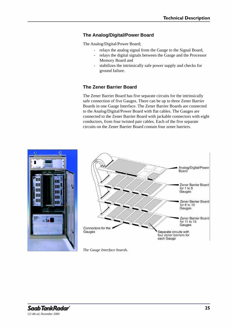
The Analog/Digital/Power Board
The Analog/Digital/Power Board;- relays the analog signal from the Gauge to the Signal Board,- relays the digital signals between the Gauge and the Processor
Memory Board and- stabilizes the intrinsically safe power supply and checks for
ground failure.
The Zener Barrier Board
The Zener Barrier Board has five separate circuits for the intrinsicallysafe connection of five Gauges. There can be up to three Zener BarrierBoards in one Gauge Interface. The Zener Barrier Boards are connectedto the Analog/Digital/Power Board with flat cables. The Gauges areconnected to the Zener Barrier Board with jackable connectors with eightconductors, from four twisted pair cables. Each of the five separatecircuits on the Zener Barrier Board contain four zener barriers.
The Gauge Interface boards.

26
Technical Description
G3 4th ed, November 2000
Power Block
The Power Block contains filters for the supply voltage, to ensure that thestrictest EMC requirements are met.
The Power Block can be set for supply voltages of either 115 or 230VAC.
There are five relays in the Power Block. Three of these relays are usedfor cargo tank IG pressure alarm, power loss and system failure. Tworelays can be controlled from the Work Station. These relays are normallynot used when a Work Station and an I/O Box are included, since therelays in the I/O Box are used instead. The I/O Box relays are controlledby the Work Station.
There is an RS-232 connector and a power outlet located in the PowerBlock for connecting a service PC to the Level Unit.
The Power Block.

27G3 4th ed, November 2000
Technical Description
The Gauge - Two Types to Cover all Applications
There are two types of Gauges with different antennas available withSaab TankRadar G3:
• Parabolic Antenna Gauge• Cone Antenna Gauge.
The Parabolic Antenna Gauge, which is the standard version, is used onall types of tanks. Due to its large antenna diameter, the radar beam fromthe Parabolic Antenna is very narrow. This makes it easy to find a goodlocation so that the radar beam can pass unobstructed in complicatedtanks with a lot of internal structures, as well as in deep and/or narrowtanks. In these cases a smaller antenna with a wider radar beam will finddisturbing echoes or will not receive a strong enough echo from thesurface of the liquid.
The Cone Antenna Gauge can be used on more shallow tanks and inspecial cases when a small socket is required due to limited space be-tween longitudinals or frames on deck.
The Gauges are prepared for inert gas pressure measurement, localreadout, and connection, from deck, of up to five RTD sensors (Resis-tance Temperature Detectors). Three of these can be used for optionalPt100 temperature sensors in a tank mounted thermowell. The other twoanalog sensors can be used for additional Pt100 sensors, for examplefrom heaters.
The Parabolíc Antenna Gauge.

28
Technical Description
G3 4th ed, November 2000
When cargo tank temperature measurement is included the TemperatureConnection Box (connecting up to three Pt100 sensors) is located ontop of the thermowell and connected via a cable to the Gauge. TheTemperature Connection Box may be deck mounted or pump mounted.
There is a wire terminal within the Gauge Housing used for connectionof the optional sensors, the Local Display and the cables to the LevelUnit.
The electronics for the Gauge are intrinsically safe and are placed in theElectronic Box. The main parts of the Electronic Box are the Micro-wave Module and the Electronic Board. The same type of ElectronicBox is used for both types of Gauges.
The Cone Antenna and the Parabolic Antenna Gauges with optional protection hoses mounted.

29G3 4th ed, November 2000
Technical Description
Parabolic Antenna Gauge
The Gauge is placed on a socket. The only part of the Gauge within thetank is the antenna consisting of a stainless steel parabolic reflector andantenna feeder. Adjustment of the direction of the antenna beam can bedone within ± 2°. The optional inert gas pressure sensor is placed withinthe Gauge Housing.
The microwave aperture on the Parabolic Antenna Gauge can be cleanedunder closed tank conditions using a brush that is entered via a checkvalve in the cleaning hatch on the socket. The cleaning hatch is includedas standard with the Parabolic Antenna Gauge.
There is an Ø 1,5” ullage plug for hand dipping and for taking samples.When the ullage cap is removed, there is a clear reference point that canbe used for hand dipping. Equipment for collecting samples up to 1.5”standard size, under closed tank conditions, can be connected to thethreaded connection.
The Parabolic AntennaGauge.
IGPressureSensor(option)
ElectronicBox
UllagePlug
WireTerminal
ParabolicReflector
AntennaFeeder
CleaningHatch
Venting Tubefor IGPressureSensor
GaugeDeck Socket(yard supply)
ProtectiveHose(option)

30
Technical Description
G3 4th ed, November 2000
Cone Antenna Gauge
The Cone Antenna Gauge is mounted on a socket with a DN200-flange.With this small flange, the Cone Antenna Gauge can be placed on a deckwhere there are many closely spaced frames or longitudinals.
The Cone Antenna Gauge can be used on more shallow tanks. A cleaningfacility is available so that the Cone Antenna Gauge can be inspected andcleaned from above.
The Cone Antenna Gauge.
ElectronicBox
Gauge Deck Socket(Yard supply)
Electronic Box
IG Pressure Sensor (option)
Cable Inlet
Protective Hose
Insulation
Stainless SteelCone Antenna
Wire Terminal

31G3 4th ed, November 2000
Technical Description
Easy Installation of Saab TankRadar G3
Saab TankRadar G3 is very convenient to install. The Gauges are placedon the deck according to a few requirements stated in the InstallationManual. The main requirement for the Gauge is that the radar beamshould be unobstructed.
The Level Unit can be placed anywhere in safe area indoor on board. It isbolted or welded to a bulkhead or to the floor.
The Work Station can be placed on the bridge, in the cargo control roomor wherever the cargo is monitored and controlled. There can be anumber of Work Stations placed in various locations on board. They arethen connected in a network.
There is only one cable from each Gauge to the Level Unit, as the tem-perature sensors and the inert gas pressure sensors are connected to theGauge. There is one communication cable between the Level Unit andthe Work Station.
Associated systems, such as load calculator and electro-pneumatic levelgauging systems, are connected to the Work Station via the I/O Box.
The Parabolic Antenna Gauge installed on deck.

32
Technical Description
G3 4th ed, November 2000
A Flexible System to Meet our Customers’Requirements
Saab TankRadar G3 is a complete system for tank gauging. As standard,Saab TankRadar G3 provides ullage, level rate, Hi, Hi.Hi, Lo and Lo.Loalarms.
The measured data is presented on one or more Work Stations with colormonitors, as well as on the Backup Display. The data can also be pre-sented on deck, at each tank on a small display, the optional LocalDisplay.
Optional Equipment for Many Purposes
There are numerous options that can be added to Saab TankRadar G3such as:
• Temperature measurement with calculation of average tempera-ture.
• Inert gas pressure measurement with instant alarm indication.• Cargo control with Saab TankRadar MaC.• Local Displays on deck.• Tank Display Units (Console mounted bargraph instrument)• Portable Readout System for reading measured values any-
where onboard.• Serial communication with load calculators.• Serial communication with electro-pneumatic ballast and draft
measurement.• Serial communication with other host computers.• Printers for alarm logs and for other reports.• Volume calculation. Normally received from an on-line load
calculator.• Weight calculation. Normally received from an on-line load
calculator.• Analog and digital inputs and outputs.• Flexible protective hose with or without flange for cables from
Gauge to deck pipe conduit.• Ballast-, HFO-, DO- etc. level gauging as well as draft gauging
(electropneumatic).• A totally independent high level and/or overfill alarm system.
See also note below.See pages 10 and 11 for an illustration of some of the optional equipment.
Many other options and optional equipment are available with the SaabTankRadar system. Contact your local agent for more information.
Note: Saab TankRadar G3 fulfills the USCG requirements CFR46,§39,20,7 a to c High Level Alarm (95%) as integrated with the cargogauging system.

33G3 4th ed, November 2000
Technical Description
Control Functions
Pumps, valves and other equipment are controlled by pressing the symbolusing the Light Pen. An indication shows that the symbol is selected. Asmall control window is opened close to the symbol, allowing the opera-tor to give commands such as open/close, start/stop or percentage set-tings. Control commands can be issued from any Work Station in anetwork.
In order to minimize the risk of handling errors, all control commands areclearly shown and are easily understood by the operator.
Feedback signals from sensors on pumps and valves can be monitoredand alarms issued if actual values differ from setpoint values.
Extensive self test functions are included in the system to alert theoperator if anything is abnormal in the system.
Example of a mimic window with symbols for control funtions.

34
Technical Description
G3 4th ed, November 2000
Temperature Measurement (Option)
Up to three Pt100 type temperature sensors can be used for each tankwith three or optionally four wire connection. They are connected in theTemperature Connection Box. The temperature is measured and sent tothe Level Unit with the same interval as the ullage.
The Temperature Connection Box can be mounted on deck, as in thefigure below. Another version of it can be mounted onto a cargo pumpwith the thermowell mounted into the tank along the pump pipes.
Inert Gas Pressure Measurement (Option)
The inert gas pressure can be measured with a sensor integrated in theGauge Housing. It is connected on a wire terminal inside the GaugeHousing. The inert gas pressure is measured and sent to the Level
The inert gas pressure sensor inside the Gauge Housing.
The deck mounted Temperature Connection Box.

35G3 4th ed, November 2000
Technical Description
Unit with the same interval as the ullage. Normal high and low pressurealarm handling is done in the Work Station. However, there is also adirect alarm handling in the Gauge itself, for handling extreme situationsvery quickly. This type of alarm is immediately sent to the Work Stationfor instant display. It can be used for example for leak alarm detection.
Local Display (Option)
The Local Display is a display that can be mounted on deck, close to avalve of the tank to which its Gauge is connected. It has a display withsix characters. The Local Display is intrinsically safe and is mountedseparately on deck up to 20 m away from the Gauge to which it is con-nected. The Local Display can display the tank’s ullage. It can also be setto automatic toggling between ullage, average temperature and inert gaspressure. It can also show alarms. The Local Display has been made sothat it can be bolted, clamped or welded to any suitable structure on deck.
The Local Display.

36
Technical Description
G3 4th ed, November 2000
Portable Readout System (Option)
Saab Marine’s Portable Readout System allows the crew on deck to havecontinuous overview of the ullages in the tanks during loading anddischarging. The system is made up of mainly two parts, the portable unitand the base radio.
The Portable Readout Unit has a display and a keyboard and is connectedto a walkie-talkie. The walkie-talkie is used for both talking and digitalcommunication.
The Portable Readout Unit displays ullage, temperature, inert gas pres-sure and alarms in alphanumeric characters on two displays. Alarms areindicated with a buzzer, and the concerned tank name is shown on thedisplay.
The information is automatically updated to the Portable Readout Unitfrom the Work Station.
As the Portable Readout Unit is intrinsically safe it can be used anywhereonboard. The Portable Readout Unit is completely sealed and containedin a leather case with a shoulder strap.
The Work Station communicates with the Portable Readout Unit via abase radio connected to a PRS Interface Card in the I/O Box. The baseradio and its antenna must be mounted in a nonhazardous area.
Saab’s PortableReadout System.
The Portable ReadoutUnit together with the
walkie-talkie is shown tothe left. The base radio
with its antenna isshown to the right.
The Portable ReadoutSystem is connected to
the Work Stationvia the I/O Box.

37G3 4th ed, November 2000
Technical Description
Tank Display Unit (Option)
One Tank Display Unit for each tank installed in a common panel gives aclear view of tank contents (ullage or innage). The standard Tank DisplayUnit has a four digit numeric display and a bargraph of light emittingdiodes (LEDs) indicating tank filling as a percentage of the tank height.The display also indicates alarm levels (Hi, Hi.Hi, Lo and Lo.Lo alarms).Values can be displayed in either metric or imperial units, which is presetat delivery.
The standard Tank Display Unit can also be adapted for temperature,ballast or draft indications.
The Tank Display Units are powered by a separate power supply unit. Upto 30 Tank Display Units can be supplied by one power supply unit.
There is an optional thumbwheel that can be used together with a singleTank Display Unit. The thumb wheel is used to select the tank to bedisplayed at the moment.
These illustrations show the TDU for ullage presentation and the TDU for temperature presentation in Celsius (°C).

38
Technical Description
G3 4th ed, November 2000
Printer (Option)
A printer can be supplied with the Saab TankRadar system for printingreports and logs of alarms and warnings.
Alarm logs are useful when you want to keep track of when alarms orwarnings occurred as well as when they went out of alarm. The printerprints one row for each alarm or warning, describing it with date, time, ifit went into or out of alarm, name of parameter that caused the alarm,value, alarm limit and unit of measurement.
Reports can also be created and printed. You can easily modify somereports for your own needs. These reports can either be printed at yourcommand or they can be set to be printed automatically at certain inter-vals, for example each week or month. Other reports may be customized.
One alternative printer is of the matrix type. This type of printer issuitable for printing alarm logs since it can print one row at a time oncontinuous paper.
Another alternative printer is the laser type. This printer is suitable forprinting screen copies or special cargo reports, e.g. LNG Custody Trans-fer Reports.

39G3 4th ed, November 2000
Technical Description
I/O Unit Cabinet
The I/O Unit Cabinet contains electronics and wire terminals for inputsignals as well as control signals. The main function of the I/O UnitCabinet is to handle the signals between the Work Station and the con-nected control equipment.
Signals from various devices, such as valve positions, pressures andtemperatures, are sent to the I/O Unit where they are processed and sentto the Work Station for presentation. When the operator orders actionsfrom a Work Station, these orders are sent to a I/O Unit. From the I/OUnit, control signals are sent to the corresponding equipment, such as on/off switches, pumps and valves.
All communication between the Work Station and the I/O Unit is trans-mitted over one or more high speed RS-485 data links.
Each I/O Unit handles input/output signals to and from:• Valves and pumps (actuators and feedbacks).• Temperature and pressure sensors• On/off switches.• Other types of sensors and equipment (refer to Technical
Specifications).
4-20 mA feedback signals from sensors in hazardous areas pass throughconventional zener barriers. Potentiometer or digital signals pass throughthe Terminal Module Intrinsic Safe Multiplexer, which can handle up to15 intrinsically safe signals.
The I/O Unit Cabinet contains the following equipment:• Terminal Module Analog In• Terminal Module Analog Out• Terminal Module Digital In• Terminal Module Digital Out• Terminal Module Intrinsic Safe Multiplexer
Terminal Module Intrinsic Safe Multiplexer.

40
Technical Description
G3 4th ed, November 2000
Work Station Redundancy (Option)
When two or more Work Stations are connected in a network, two ofthem can be configured as masters and be connected to the RedundancyBox. If the active master Work Station fails, the redundant master willautomatically detect this and take over control of the system.
The redundant master Work Station monitors the QNX network, andwhen it notices that the active master Work Station has failed, it takesover control. In order to become the active master it has to restart itssoftware. It takes approximately one minute after the active master WorkStation fails, until the redundant master Work Station has taken over asactive master.
The Redundancy Box switches the signal to the active master. The activemaster has exclusive control over the Redundancy Box. Only one of themaster Work Stations is active at any one time.
The redundant master Work Station works like any slave Work Stationuntil it detects that the active master has failed.
A Saab TankRadar MaC system with redundant Work Stations. If the Master Work Station fails, the redundantmaster Work Station takes over and becomes active master.

41G3 4th ed, November 2000
Technical Description
Technical Specification
Gauge
Instrument accuracy ± 3 mm
Operational accuracy ± 5 mm
Resolution 1 mm
Operating temperature -40 to +80 °C (-40 to +176 °F)
Maximum temperature of product +120 °C (+248 °F) standard.Optional isolation of the Gaugesfor bitumen tankers
Product range Crude, products, chemicals,bitumen, molten sulphur etc.
Analog inputs Five inputs for either 3-wire or 4-wire Pt100 sensors, scalable rangeOne input for inert gas pressuresensor.
Explosion protection Intrinsically safe:
• EEx ia IIC T4 according to EN50020 (European Norm)
• Accepted by USCG and ABS
Parabolic Antenna Gauge
Measuring range 0-60 m
Ullage reference plug Inner diameter 1.5”
Socket (Yard supply) Height 500 mm
Flange DN500 (Outer tube diameter 532mm)
Antenna diameter 440 mm
Beam width 2.7° (3-dB beam width fromantenna axis)
Free space requirement 5.0° (angle from antenna axis)
Material facing tank atmosphere Stainless steel 316L, PTFE (Te-flon).Other materials optional
Weight 50 kg (deck socket excluded)

42
Technical Description
G3 4th ed, November 2000
Cone Antenna Gauge
Measuring range 0-14 m
Socket (Yard supply) Height 120 mm
Flange DN200 (Flange outer diameter 340mm, pipe outer diameter 219 mm)
Beam width 6.2° (3-dB beam width fromantenna axis)
Free space requirement 7.5° (angle from antenna axis)
Material facing tank atmosphere Stainless steel SS2343 andPTFE (Teflon).Other materials optional
Weight 45 kg (deck socket excluded)
Level Unit
Number of Gauges Max 30 for one Level UnitMax 60 with an additional SlaveLevel Unit
Dimensions 550 x 1200 x 300 mm(Width x Height x Depth)
Weight 68 kg
Power supply 115 VAC +10 to -15%, 47-63 Hzor230 VAC +10 to -15%, 47-63 Hz
Power consumption Max 250 VA for standard LU with30 Gauges connected.Recommended fuse: 10 A, 250 V
Alarm relays Five relays, rated 250 VAC, 2 A(system failure, pressure alarm,power failure and two spares)
Intrinsic safety Associated apparatus for nonhaz-ardous location:[EEx ia] IIC T4(provides intrinsic safety forequipment in hazardous location)
Cables from each Gauge 2 x 4 twisted wire cable withcommon shieldArea 0.50-1.50 mm2
(max length:- with 0.50 mm2 = 200 m- with 0.75 mm2 = 325 m- with 1.00 mm2 = 480 m- with 1.25 mm2 = 520 m- with 1.50 mm2 = 670 m)Yard supply

43G3 4th ed, November 2000
Technical Description
Operating temperature 0 to +55 °C (32 to 131 °F)
Connection to Work Station RS-485 (two wire with halfduplex) via I/O BoxMax distance 400 mCable type: twisted pair withcommon shield
Connection to Service PC RS-232
Trim/List Unit
Inclinometer range ±5°
Inclinometer accuracy ±0.08°
Work Station
Computer Type approved PC
Monitor Saab TankRadar G3 17” monitor
Monitor Saab TankRadar MaC 21” monitor
Operating System QNX
Power supply 115 VAC +10 to -15%, 47-63 Hzor230 VAC +10 to -15%, 47-63 Hz
Power consumption Max 300 VA
Connection of associated equipment Via the I/O Box
Dimensions
PC, Monitor, mounting plate 415 x 545 x 425 mm
Keyboard 470 x 40 x 195 mm(Width x Height x Depth)
Weight 35 kg
I/O Box
Serial communication interfaces Up to seven galvanically isolatedRS-232 (max 15 m) orRS-485 (max 400 m) of which oneis dedicated for LU communica-tion.
Communication Protocol Saab Master/Slave Protocol.
Relays System failure, common alarm andup to six configurable relays foralarms or general output signalsRated 250 VAC, 8 A

44
Technical Description
G3 4th ed, November 2000
Analog/digital inputs/outputs Field bus interface for distributedI/O modules
Connection to Work Station RS-232, max 15 m. Cable suppliedby Saab Marine Electronics
Power supply 115 VAC +10 to -15%, 47-63 Hzor230 VAC +10 to -15%, 47-63 Hz
Power consumption Max 15 VA
Dimensions 280 x 230 x 110 mm(Width x Height x Depth)
Weight 5 kg
Redundancy Box (Optional)
Connection to Work Station RS-232 max 3 m Cable suppliedby Saab Marine Electronics
Power supply 115 VAC +10 to -15%, 47-63 Hzor230 VAC +10 to -15%, 47-63 Hz
Power consumption Max 15 VA
Dimensions 280 x 230 x 110 mm(Width x Height x Depth)
Weight 5 kg
Temperature Measurement (Optional)
Operational accuracy, standard 3 wire ± 0.2 °C excluding sensor accu-racy for temperature range0 °C to +100 °C (+32 to + 212 °F)
Sensor accuracy, standard ± 0.3 °C + 0.005 ∆T for Pt100Class B sensor (ex. ±0.3 °C at 0 °Cand ±0.55 °C at +50 °C)
Optional for custody transfer ± 0.15 °C excluding sensor accu-racy for temperature range0 °C to +100 °C. 4-wire connec-tion in Gauge. Class 1_
3 B sensorrecommended
Temperature range Whole or part of -50 °C to +250°C (-58 to +482 °F)

45G3 4th ed, November 2000
Technical Description
Inert Gas Pressure Measurement (Optional)
Operational accuracy ± 5 mBar excluding sensor accu-racy
Sensor accuracy, standard ± 2 % of full scale for operatingenvironment
Pressure range ± 500 mBar.Extended range ±800 mBaravailable
Local Display (Optional)
Resolution 1 mm, 0.1 °C, 1 mBar
Operating temperature -40 °C to +80 °C(-40 to +176 °F)
Distance to Gauge Max 20 m
Explosion protection Intrinsically safe, EEx ia IIC T4
Dimensions 120 x 195 x 126 mm(Width x Height x Depth)
Weight 6 kg
Material Stainless steel
Tank Display Unit (Optional)
Resolution 50 LEDs in bargraph represent fulltank height. Numeric displayshows ullage in cm.
Operating Temperature 0-55 °C(+32 to +131 °F)
Dimensions, TDU 48 x 168 x 200 mm(Width x Height x Depth)
Signal cables RS-485, 3 twisted pairs withcommon shield. Area: 0.5-1.5 mm2
From TDU Power Supply to TDU: 2 x 1.5 mm2 (max 10 TDU/cablepair)
Weight, TDU 0.7 kg

46
Technical Description
G3 4th ed, November 2000
TDU Power Supply Unit
Dimensions 285 x 325 x 100 mm(Width x Height x Depth)
Weight 10 kg
Power Supply for 1 - 30 Units 115 VAC +10 to -15%, 47-63 Hzor230 VAC +10 to -15%, 47-63 Hz
Power consumption Max 100 VA
Portable Readout System (Optional)
Portable Readout Unit
Intrinsic safety According to CENELEC (Europe)and FM (USA)
Resolution
Ullage/innage 0.01 m
Temperature 0.1 °C
IG Pressure 1 mBar
Power requirements 2-4 mA, 7-15 V (supplied fromwalkie-talkie)
Dimensions 120 x 190 x 45 including leathercase (Width x Height x Depth)
Weight 0,6 kg (including leather case)
Operating temperature -20 to +50 °C (-4 to +122 °F)
Storage temperature -55 to +60 °C (-67 to +140 °F)
Available Standard Frequencies
VHF 157.525, 157.550, 157.575 MHz
UHF 457.525, 457.550, 457.575 MHz
Walkie-Talkie
Type Motorola MT2100
Base Radio
Type Motorola Mobius 900 or MotorolaMax-Trac 50

47G3 4th ed, November 2000
Technical Description
Printer (Optional)
Dimensions 430 x 120 x 310(Width x Height x Depth)
Weight 5.2 kg
Power supply 115 VAC +10 to -15%, 47-63 Hzor230 VAC +10 to -15%, 47-63 Hz
Connection Parallel port on Work Station
I/O Unit Cabinet for Saab TankRadar MaC Cargo Control System (Optional)
Cabinet
Dimensions 620 x 1962 x 520 mm(Width x Height x Depth)
Weight 180 kg
Power supply 110 VAC +10 to -15%, 50-60 Hzor230 VAC +10 to -15%, 50-60 Hzor24 VDC
Power consumption 300 VA, max
Ambient operating temperature 0 to 55 °C (+32 to +131 °F)
TMXX I/O Terminal Modules
Communication type RS485
Communication speed 115 kb/s
Isolation Optocoupled (in I/O box)
Module size 160 x 100 x 80 mm(Width x Height x Depth)
Mounting method DIN rail (35 mm) clip
Supply voltage 24 VDC
Approved environment 0 to +55°C

48
Technical Description
G3 4th ed, November 2000
TMAI Analog in (0(4)-20 mA, 0-10 V)
Channels 16 single ended
Input load 50 Ω (curr.), 10 kΩ (voltage)
Accuracy (current) Max ± 0.5 % of full range
Temp drift (current) Accuracy valid for 0 - 55°C
Accuracy (voltage) Max ± 0.5 % of full range
Temp drift (voltage) Accuracy valid for 0 - 55°C
TMAO Analog out (0(4)-20 mA, 0-10 V)
Channels 16 single ended
Load impedance 50 Ω / max 500 Ω
Load current < 5 mA for 0 - 10 VDC
Accuracy (current) Max ± 0.5 % of full range
Temp drift (current) Accuracy valid for 0 - 55°C
Accuracy (voltage) Max ± 0.2 % of full range
Temp drift (voltage) Accuracy valid for 0 - 55°C
TMDI Digital in
Channels 16 negative common
Voltage range input 0 to +35 VDC
Source type Potential free contact
Input current Max 0.6 mA
TMDO Digital out
Channels 8 pot free SPDT
Capacity Max 250 VAC, 2 A
Relay expansion module (higher ratings) (OEM supply)
Channels Individually selected
Capacity T b d
TMIX Intrinsically Safe Multiplexer
Channels 15
Safety level [EEx ia] IIC
Input types For 3-wire potentiometer
Resistance range 1 kΩ to 10 kΩ

49G3 4th ed, November 2000
Technical Description
Limit detection 0 Ω and h (short/open)
Accuracy Max ± 2% of full range,typically < 1%
Note: Due to constant development, specifications may be subject tochange without prior notification. All specifications in this publicationare based on functions and features that can be included on demand. Fora specific description of included functions and features, please refer tothe technical data stated in the quotation in response to your inquiry forquotation, or in the order acknowledgment.

50
Technical Description
G3 4th ed, November 2000
Index
A
A/D converter 22Accuracy
IG pressure measurement 45Temperature measurement 44Ullage 41
Alarm handling 12Alarm relays 42Analog filters 22Analog in- and outputs 19Analog inputs 18, 41Analog signal 25Analog/Digital/Power Board 25Antenna adjustment 29Antenna diameter 27
B
Backup Display 20, 23
C
Cables 25, 31, 42Calculation Unit 20, 22, 24Cleaning antenna
Cone Antenna 30Parabolic Antenna 29
Cleaning hatch 29Cone Antenna Gauge 27, 30, 42Configuration 17
D
Database memory 22Deep tanks 27Digital in- and outputs 19Digital signal 25Disturbing echoes 27
E
Electrical Safety 13Electromagnetic Compatibility 20Electronic Box 28EMC 20, 26Environment 14European Norm 13Explosion protection 13, 41
F
FlangeCone Antenna 42Parabolic Antenna 41
G
Gauge 12, 15, 20, 21, 24, 27, 41Gauge Interface 20, 21, 24Ground failure alarm 22
H
Hand dipping 29
I
I/O Box 19, 43I/O Unit Cabinet 39, 47Inert Gas pressure 12, 27, 34
Measurement 32, 34, 45Information flow 21Installation 31Interface Board 21, 22Internal structures 27Intrinsic safety 8, 13, 24, 25, 28, 41, 42
K
Keyboard 17
L
Level Unit 12, 20, 42Installation 31
Light pen 17Limited space 27, 30Load calculator 12, 31, 32Local Display 12, 32, 35, 45
Connection 28
M
Measuring range 41Microwave Module 28Multiplexer 48Multiplexers 24, 39

51G3 4th ed, November 2000
Technical Description
N
Network 18Non-Contact Gauging 15
O
On/off switches 39Options 18, 32Overfill alarm system 32
P
Parabolic Antenna Gauge 27, 29, 41Installation 31
Portable Readout System 36, 46Power Block 20, 24, 26Power loss alarm 26Power outlet 26Power supply
I/O Box 44Level Unit 42Power Block 26Tank Display Unit 46Work Station 43
Pressure alarm 26Printer 32, 47Processor Memory Board 21, 22, 25Product range 41Pump 39
Q
QNX 18
R
Radar beam 14, 27, 41Radar principle 14, 15Radar signal 15Redundancy Box 40, 44Relays 26Reliability 14RS-232 connection 26
S
Saab Cargo Control System 9Saab TankRadar MaC 9, 11, 32Safety 8Serial communication 32Service PC 26Signal Board 21, 22, 24, 25Slave Level Unit 20, 24Small socket 27SUM 21 8System failure alarm 26
T
Tank Display Unit 32, 37, 45Temperature 39Temperature Connection Box 28Temperature measurement 32, 34, 44Temperature sensors 12, 27, 34Terminal Modules 39, 47Thermowell 27Trim/list correction 18Trim/List Unit 23
U
Ullage plug 29
V
Valve 39
W
Work Station 12, 17, 43Installation 31Redundancy 40
Z
Zener Barrier Board 25Zener barriers 24

52
Technical Description
G3 4th ed, November 2000