s800 i/o, modules and termination units with intrinsic ... · the s800 i/o provides easy...
TRANSCRIPT
Power and productivity
for a better worldTM
S800 I/OModules and Termination Units with Intrinsic Safety Interface


S800 I/O Modules and Termination Units with Intrinsic Safety Interface

NOTICEThis document contains information about one or more ABB products and may include a description of or a reference to one or more standards that may be generally relevant to the ABB products. The presence of any such description of a standard or reference to a standard is not a representation that all of the ABB products referenced in this document support all of the features of the described or referenced standard. In order to determine the specific features supported by a particular ABB product, the reader should consult the product specifications for the particular ABB product.
ABB may have one or more patents or pending patent applications protecting the intel-lectual property in the ABB products described in this document.
The information in this document is subject to change without notice and should not be construed as a commitment by ABB. ABB assumes no responsibility for any errors that may appear in this document.
In no event shall ABB be liable for direct, indirect, special, incidental or consequential damages of any nature or kind arising from the use of this document, nor shall ABB be liable for incidental or consequential damages arising from use of any software or hard-ware described in this document.
This document and parts thereof must not be reproduced or copied without written per-mission from ABB, and the contents thereof must not be imparted to a third party nor used for any unauthorized purpose.
The software or hardware described in this document is furnished under a license and may be used, copied, or disclosed only in accordance with the terms of such license. This product meets the requirements specified in EMC Directive 2004/108/EC and in Low Volt-age Directive 2006/95/EC.
TRADEMARKSAll rights to copyrights, registered trademarks, and trademarks reside with their respec-tive owners.
Copyright © 2003-2014 by ABB. All rights reserved.
Release: August 2014Document number: 3BSE020927-600
3BSE020927-600 5
TABLE OF CONTENTS
About This BookGeneral ..............................................................................................................................9
Use of Warning, Caution, Information, and Tip Icons ....................................................10
Terminology.....................................................................................................................11
Applicable Specifications ................................................................................................11
Related Documentation ...................................................................................................12
Section 1 - IntroductionProduct Overview............................................................................................................14
Module Termination Units ...................................................................................14
I/O Modules .........................................................................................................16
Prerequisites and Requirements ......................................................................................18
Section 2 - InstallationPowering..........................................................................................................................19
Hazardous Area Interfacing.............................................................................................19
General Description of an I.S. System ............................................................................20
I.S. System Design Considerations .................................................................................21
Grounding Information ........................................................................................21
Wiring of Intrinsically Safe Circuits................................................................................22
Mounting Equipment in Zone 2 Hazardous Areas ..........................................................23
Marking to ATEX Directive ............................................................................................24
Section 3 - ConfigurationModule Termination Units (MTU) ..................................................................................27
I/O Modules.....................................................................................................................28
Table of Contents
6 3BSE020927-600
Section 4 - MaintenancePreventive Maintenance .................................................................................................. 29
Hardware Indicators ........................................................................................................ 29
I/O Module LEDs ................................................................................................ 29
Error Messages................................................................................................................ 31
Fault Finding and User Repair ........................................................................................ 31
I/O Module Replacement..................................................................................... 31
Appendix A - SpecificationsAI890 Analog Input Module, 0...20 mA......................................................................... 35
Features ............................................................................................................ 35
Description........................................................................................................... 35
Technical Data ..................................................................................................... 37
Intrinsic Safety Parameters .................................................................................. 39
Block Diagram AI890.......................................................................................... 40
Process Connections ............................................................................................ 40
AI893 Analog Input Module, for RTD and TC sensors.................................................. 43
Features ............................................................................................................ 43
Description........................................................................................................... 43
Technical Data ..................................................................................................... 45
Intrinsic Safety Parameters .................................................................................. 49
Block Diagram AI893.......................................................................................... 50
Process Connections ............................................................................................ 50
AI895 Analog Input Module, 4...20 mA and HART....................................................... 55
Features ............................................................................................................ 55
Description........................................................................................................... 55
Technical Data ..................................................................................................... 57
Intrinsic Safety Parameters .................................................................................. 59
Hart Communication............................................................................................ 59
Block Diagram AI895.......................................................................................... 61
Process Connections ............................................................................................ 61
AO890 Analog Output Module, 0...20 mA..................................................................... 65
Table of Contents
3BSE020927-600 73BSE020927-600 7
Features .............................................................................................................65
Description ...........................................................................................................65
Technical Data .....................................................................................................68
Intrinsic Safety Parameters ..................................................................................70
Block Diagram AO890 ........................................................................................70
Process Connections.............................................................................................71
AO895 Analog Output Module, 4...20 mA and HART...................................................73
Features .............................................................................................................73
Description ...........................................................................................................73
Technical Data .....................................................................................................75
Hart Communication............................................................................................77
Intrinsic Safety Parameters .................................................................................78
Block Diagram AO895 ........................................................................................78
Process Connections.............................................................................................79
DI890 Digital Input Module, Switch/Prox. .....................................................................81
Features .............................................................................................................81
Description ...........................................................................................................81
Technical Data......................................................................................................83
Intrinsic Safety Parameters .................................................................................85
Block Diagram DI890 ..........................................................................................85
Process Connections.............................................................................................86
DO890 Digital Output Module........................................................................................88
Features .............................................................................................................88
Description ...........................................................................................................88
Technical Data......................................................................................................90
Intrinsic Safety Parameters ..................................................................................91
Output Characteristic ...........................................................................................92
Block Diagram DO890 ........................................................................................93
Process Connections.............................................................................................95
TU890 Intrinsic Safety Compact MTU...........................................................................96
Features .............................................................................................................96
Description ...........................................................................................................96
Table of Contents
8 3BSE020927-600
Technical Data ..................................................................................................... 97
Connections ...................................................................................................... 100
Block Diagram TU890....................................................................................... 101
TU891 Compact MTU .................................................................................................. 102
Features .......................................................................................................... 102
Description......................................................................................................... 102
Technical Data ................................................................................................... 103
Connections ...................................................................................................... 106
Block Diagram TU891....................................................................................... 107
Appendix B - Introduction to ATEX DirectivesScope ........................................................................................................................... 109
General .......................................................................................................................... 109
Defining the Group and Category of Equipment .......................................................... 110
Group I .......................................................................................................... 111
Group II .......................................................................................................... 111
Group I, Category .............................................................................................. 111
Group II, Category ............................................................................................. 112
Levels of Protection for various Categories of Equipment................................ 113
INDEX
3BSE020927-600 9
About This Book
GeneralThis book provides a description of the S800 I/O modules and termination units with intrinsic safety interface. It provides instructions for site planning and installation, start-up and shutdown procedures, and information regarding capacity and performance. This book is not intended to be the sole source of instruction for the S800 I/O system.
This section provides introductory and background information including guidelines on how to find information in the relevant user documentation.
Section 1, Introduction provides a product and functional overview.
Section 2, Installation guides during installation.
Section 3, Configuration will give you the information needed to obtain the desired function. The main information is structured as follow:
• Design considerations and guidelines are given.
• Capacity and performance.
Section 4, Maintenance focus is on fault finding supported by built in diagnostics and use of system status displays in operator station and LEDs on I/O modules.
In Appendix A, you will find data sheets of all components of S800 I/O. They are listed in alphabetical order.
In general, the data sheet contains the following information:
• Features
• Description
• Front view
Use of Warning, Caution, Information, and Tip Icons About This Book
10 3BSE020927-600
• Technical data
• Process connections.
Appendix B, Introduction to ATEX Directives will give you an introduction to ATEX directives.
Use of Warning, Caution, Information, and Tip Icons
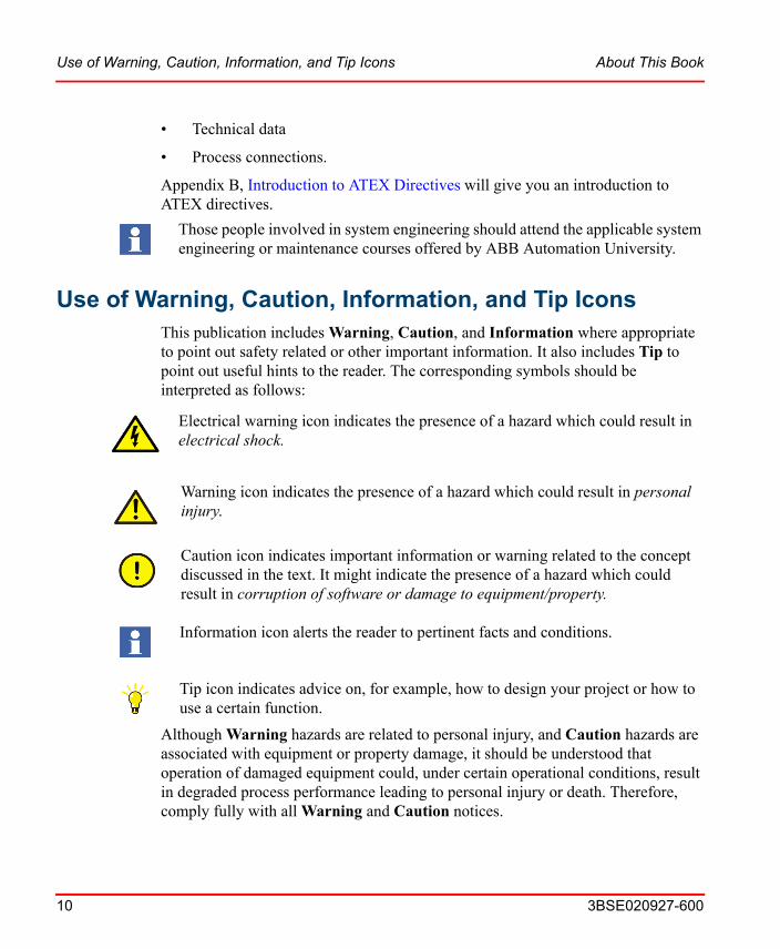
Warning icon indicates the presence of a hazard which could result in personal injury.
Caution icon indicates important information or warning related to the concept discussed in the text. It might indicate the presence of a hazard which could result in corruption of software or damage to equipment/property.
Information icon alerts the reader to pertinent facts and conditions.
Tip icon indicates advice on, for example, how to design your project or how to use a certain function.
This publication includes Warning, Caution, and Information where appropriate to point out safety related or other important information. It also includes Tip to point out useful hints to the reader. The corresponding symbols should be interpreted as follows:
Although Warning hazards are related to personal injury, and Caution hazards are associated with equipment or property damage, it should be understood that operation of damaged equipment could, under certain operational conditions, result in degraded process performance leading to personal injury or death. Therefore, comply fully with all Warning and Caution notices.
Those people involved in system engineering should attend the applicable system engineering or maintenance courses offered by ABB Automation University.
Electrical warning icon indicates the presence of a hazard which could result in electrical shock.
About This Book Terminology
3BSE020927-600 11
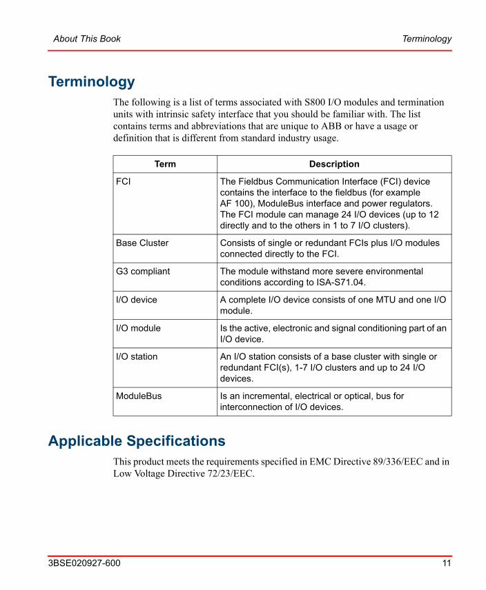
TerminologyThe following is a list of terms associated with S800 I/O modules and termination units with intrinsic safety interface that you should be familiar with. The list contains terms and abbreviations that are unique to ABB or have a usage or definition that is different from standard industry usage.
Applicable SpecificationsThis product meets the requirements specified in EMC Directive 89/336/EEC and in Low Voltage Directive 72/23/EEC.
Term Description
FCI The Fieldbus Communication Interface (FCI) device contains the interface to the fieldbus (for example AF 100), ModuleBus interface and power regulators. The FCI module can manage 24 I/O devices (up to 12 directly and to the others in 1 to 7 I/O clusters).
Base Cluster Consists of single or redundant FCIs plus I/O modules connected directly to the FCI.
G3 compliant The module withstand more severe environmental conditions according to ISA-S71.04.
I/O device A complete I/O device consists of one MTU and one I/O module.
I/O module Is the active, electronic and signal conditioning part of an I/O device.
I/O station An I/O station consists of a base cluster with single or redundant FCI(s), 1-7 I/O clusters and up to 24 I/O devices.
ModuleBus Is an incremental, electrical or optical, bus for interconnection of I/O devices.
Related Documentation About This Book
12 3BSE020927-600
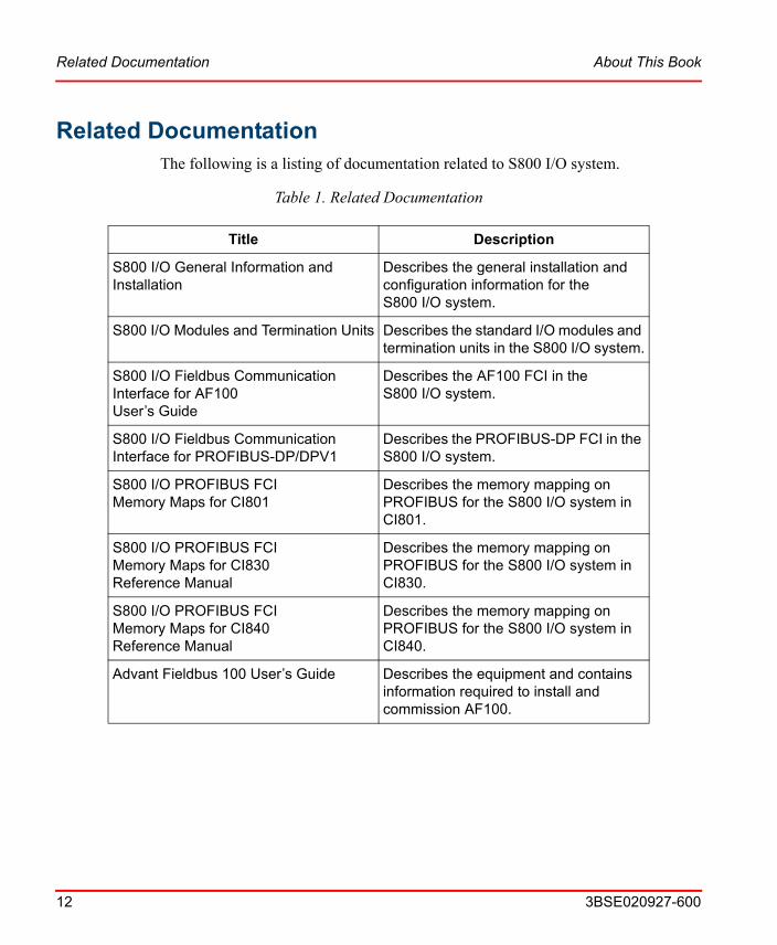
Related DocumentationThe following is a listing of documentation related to S800 I/O system.
Table 1. Related Documentation
Title Description
S800 I/O General Information and Installation
Describes the general installation and configuration information for the S800 I/O system.
S800 I/O Modules and Termination Units Describes the standard I/O modules and termination units in the S800 I/O system.
S800 I/O Fieldbus Communication Interface for AF100User’s Guide
Describes the AF100 FCI in the S800 I/O system.
S800 I/O Fieldbus Communication Interface for PROFIBUS-DP/DPV1
Describes the PROFIBUS-DP FCI in the S800 I/O system.
S800 I/O PROFIBUS FCIMemory Maps for CI801
Describes the memory mapping on PROFIBUS for the S800 I/O system in CI801.
S800 I/O PROFIBUS FCIMemory Maps for CI830Reference Manual
Describes the memory mapping on PROFIBUS for the S800 I/O system in CI830.
S800 I/O PROFIBUS FCIMemory Maps for CI840Reference Manual
Describes the memory mapping on PROFIBUS for the S800 I/O system in CI840.
Advant Fieldbus 100 User’s Guide Describes the equipment and contains information required to install and commission AF100.

3BSE020927-600 13
Section 1 Introduction
The S800 I/O is distributed modular I/O which communicates with numerous controllers over a Advant Fieldbus 100 (AF100), PROFIBUS-DP or directly. The S800 I/O provides easy installation of the I/O modules and process cabling. It is highly modularized and flexible so that I/O modules can be combined to suit many applications. The S800 I/O can be mounted in many configurations to fit most requirements.
Figure 1. S800 I/O Fieldbus Communication Interface with an I/O Module on Compact and Extended MTUs and an S800L I/O Module
Product Overview Section 1 Introduction
14 3BSE020927-600
Product OverviewThe S800 I/O provides easy installation of the I/O modules and process cabling. It is highly modularized and flexible so that the I/O modules can be combined to suit many applications. The S800 I/O modules and a Fieldbus Communication Interface (FCI) are combined to form an I/O Station.
For more overview information refer S800 I/O General Information and Installation (3BSE020923R5xxxx) manual.
Module Termination Units
The Module Termination Units (MTU) are passive base units used to house the I/O modules. They contain the process wiring terminals and power supply terminals and a section of the ModuleBus.
The MTU distributes the ModuleBus to the I/O module and to the next MTU. It also generates the correct address to the I/O module by shifting the outgoing position signals to the next MTU.
Two mechanical keys are used to configure the MTU for different types of I/O modules. This is only a mechanical configuration and it does not affect the functionality of the MTU or the I/O module. Each key has six positions, which gives a total number of 36 different configurations. The configuration can be changed with a screwdriver.
The MTU can be mounted on a standard DIN rail. It has a mechanical latch that locks the MTU to the DIN rail. The latch can be released with a screwdriver.
The MTU has a mechanical locking mechanism that locks the module in its position. This mechanism also gives the signal BLOCK to the I/O module that keeps the module in its initial state until it is locked in its position.
The top part of the MTU can be removed to replace the termination board even with an operational system. Such a need can be caused by a damaged terminal screw.
There are MTUs for Intrinsic Safety, non Intrinsic Safety application and also in G3 compliant versions.
The MTUs for Intrinsic Safety interfacing are available in a compact version and provides for a compact installation of the I/O modules and field circuit power
Section 1 Introduction Module Termination Units
3BSE020927-600 15
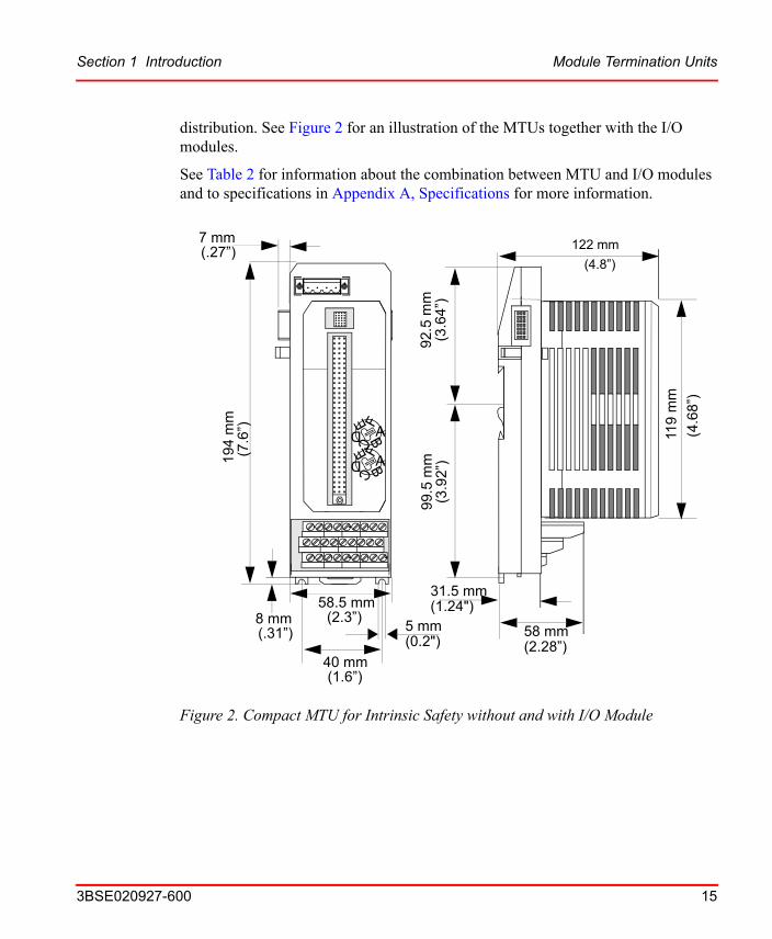
distribution. See Figure 2 for an illustration of the MTUs together with the I/O modules.
See Table 2 for information about the combination between MTU and I/O modules and to specifications in Appendix A, Specifications for more information.
Figure 2. Compact MTU for Intrinsic Safety without and with I/O Module
ABCD
E F
ABCD
E F
19
4 m
m
58.5 mm8 mm
7 mm
5 mm
(.27”)(7
.6”)
(2.3”) (.31”) (0.2")
58 mm(2.28”)
122 mm
(4.8”)
(4.6
8”)
119
mm
40 mm(1.6”)
92.
5 m
m(3
.64”
)9
9.5
mm
(3.9
2”)
31.5 mm (1.24")
I/O Modules Section 1 Introduction
16 3BSE020927-600
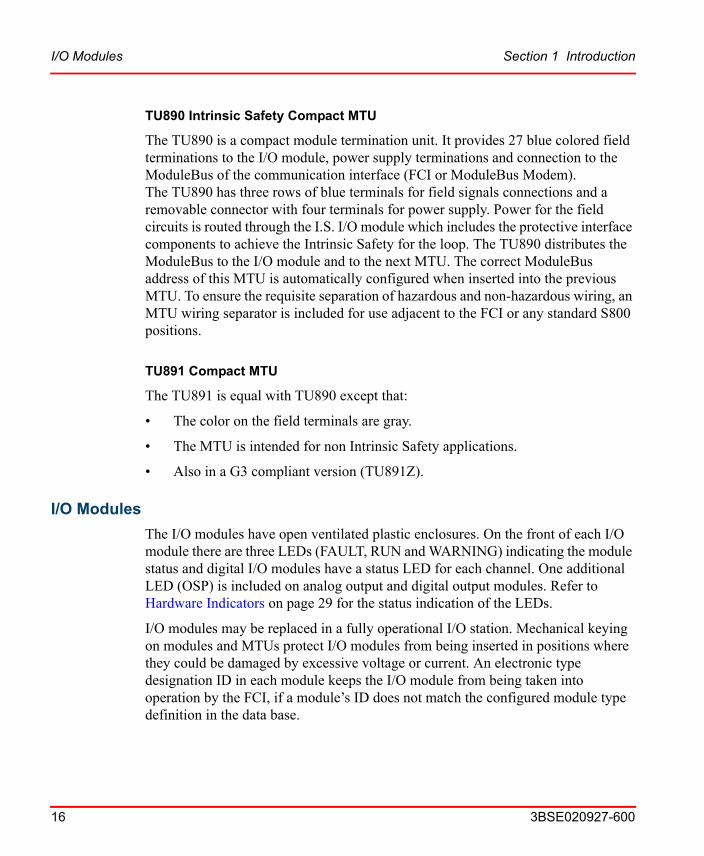
TU890 Intrinsic Safety Compact MTU
The TU890 is a compact module termination unit. It provides 27 blue colored field terminations to the I/O module, power supply terminations and connection to the ModuleBus of the communication interface (FCI or ModuleBus Modem). The TU890 has three rows of blue terminals for field signals connections and a removable connector with four terminals for power supply. Power for the field circuits is routed through the I.S. I/O module which includes the protective interface components to achieve the Intrinsic Safety for the loop. The TU890 distributes the ModuleBus to the I/O module and to the next MTU. The correct ModuleBus address of this MTU is automatically configured when inserted into the previous MTU. To ensure the requisite separation of hazardous and non-hazardous wiring, an MTU wiring separator is included for use adjacent to the FCI or any standard S800 positions.
TU891 Compact MTU
The TU891 is equal with TU890 except that:
• The color on the field terminals are gray.
• The MTU is intended for non Intrinsic Safety applications.
• Also in a G3 compliant version (TU891Z).
I/O Modules
The I/O modules have open ventilated plastic enclosures. On the front of each I/O module there are three LEDs (FAULT, RUN and WARNING) indicating the module status and digital I/O modules have a status LED for each channel. One additional LED (OSP) is included on analog output and digital output modules. Refer to Hardware Indicators on page 29 for the status indication of the LEDs.
I/O modules may be replaced in a fully operational I/O station. Mechanical keying on modules and MTUs protect I/O modules from being inserted in positions where they could be damaged by excessive voltage or current. An electronic type designation ID in each module keeps the I/O module from being taken into operation by the FCI, if a module’s ID does not match the configured module type definition in the data base.
Section 1 Introduction I/O Modules
3BSE020927-600 17
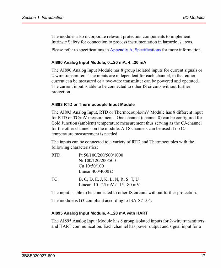
The modules also incorporate relevant protection components to implement Intrinsic Safety for connection to process instrumentation in hazardous areas.
Please refer to specifications in Appendix A, Specifications for more information.
AI890 Analog Input Module, 0...20 mA, 4...20 mA
The AI890 Analog Input Module has 8 group isolated inputs for current signals or 2-wire transmitters. The inputs are independent for each channel, in that either current can be measured or a two-wire transmitter can be powered and operated. The current input is able to be connected to other IS circuits without further protection.
AI893 RTD or Thermocouple Input Module
The AI893 Analog Input, RTD or Thermocouple/mV Module has 8 different input for RTD or TC/mV measurements. One channel (channel 8) can be configured for Cold Junction (ambient) temperature measurement thus serving as the CJ-channel for the other channels on the module. All 8 channels can be used if no CJ- temperature measurement is needed.
The inputs can be connected to a variety of RTD and Thermocouples with the following characteristics:
RTD: Pt 50/100/200/500/1000Ni 100/120/200/500Cu 10/50/100Linear 400/4000
TC: B, C, D, E, J, K, L, N, R, S, T, ULinear -10...25 mV / -15...80 mV
The input is able to be connected to other IS circuits without further protection.
The module is G3 compliant according to ISA-S71.04.
AI895 Analog Input Module, 4...20 mA with HART
The AI895 Analog Input Module has 8 group isolated inputs for 2-wire transmitters and HART communication. Each channel has power output and signal input for a

Prerequisites and Requirements Section 1 Introduction
18 3BSE020927-600
two-wire transmitter. The current input is able to be connected to other IS circuits without further protection.
The module is G3 compliant according to ISA-S71.04.
AO890 Analog Output Module, 0...20 mA, 4...20mA
The AO890 Analog Output Module has 8 group isolated current outputs. State of outputs can be set to a predetermined (OSP) value if a communications error is detected. Open wire fault detection if output is set >1mA.
AO895 Analog Output Module, 4...20 mA with HART
The AO895 Analog Output Module has 8 group isolated current outputs and HART communication. State of outputs can be set to a predetermined (OSP) value if a communications error is detected. Open wire fault detection if output is set >1mA.
The module is G3 compliant according to ISA-S71.04.
DI890 Digital Input Module, Switch/Prox.
The DI890 Digital Input Module has 8 fully isolated channels. The inputs are fully isolated and can be connected to volt-free contacts or NAMUR proximity switches. Line faults can be detected and signalled.
DO890 Digital Output Module
The DO890 Digital Output Module has 4 fully isolated channels for current sourcing digital outputs to drive I.S. solenoid valves. The outputs are fully isolated and include line fault detection of open or short circuits in the field. Faults can be detected in both the energized and non-energized state of the output. State of outputs can be set to a predetermined (OSP) value if a communications lost error is detected.
Prerequisites and RequirementsIn order to use the S800 I/O modules, an ModuleBus master is needed, i.e. CI830, CI840A, CI801, TB820V2, TB840A or AC 800M controller.
3BSE020927-600 19
Section 2 Installation
Powering
Hazardous Area InterfacingCorrect and safe operation of S890 equipment calls for expert installation and commissioning as well as correct operation and meticulous maintenance. Only those persons conversant with the installation, commissioning, operation and maintenance of similar apparatus and who has the necessary qualifications should be permitted to work on these products.
The installation must be performed by qualified personnel. It must comply with the relevant national/international standards IEN 60079-14, IEC 60070-14 and in line with the established installation rules and recommended practice contained therein. Hazardous area devices should comply with the related system documentation; their conformity must always be checked.
This instrumentation IS NOT intended for hazardous area installation unless it is included in an enclosure which conforms to the applicable standards.
When required, the I/O modules can be installed in a Zone 2 hazardous area, see Marking to ATEX Directive on page 24 for details. The modules have been designed to satisfy the IP20 protection classification according to EN 60259; in adverse environmental conditions, such as water spray or dirt, they must be
The S890 I/O system must be powered from SELV/PELV power supplies.
Make sure installation is carried out observing the safety regulations pertaining to the installation and operation of electrical systems and the directives and guidelines on explosion protection and prevention.
General Description of an I.S. System Section 2 Installation
20 3BSE020927-600
protected accordingly. For more information about the constraints imposed by the I.S. regulations consult your local representative.
General Description of an I.S. SystemAn Intrinsically Safe system is composed by an assembly of intrinsically safe apparatus, associated apparatus and interconnecting cables, where the following definitions apply:
• Simple Apparatus
Electrical component or combination of components of simple construction that is compatible with the intrinsic safety of the circuit in which it is used.
Passive components (i.e. switches, junction boxes, resistors, simple semiconductors devices etc.), sources of stored energy with well-defined parameters (i.e. capacitors and inductors) and sources of generated energy (i.e. thermocouples, photocells etc.) which do not generate more than 1.5V, 100mA and 25mW, are regarded as simple apparatus.They do not need any certification or marking.
• Intrinsically Safe Apparatus
Electrical apparatus in which all circuits are intrinsically safe. It must have suitable approval for the hazardous (classified) location where it will be mounted: the certificate specifies the safety parameters of the apparatus as: Ui; Ii; Pi; Ci; Li. (e.g. Proximity Switches, Transmitters, Active Sensors, magnetic pick-up etc. must be Intrinsically Safe Certified).
• Associated Apparatus
Electrical apparatus that contains both intrinsically and non-intrinsically safe circuits and is constructed so that the non-intrinsically safe circuits cannot adversely affect the intrinsically safe circuits.
If you intend to re-use I.S. certified modules in a Intrinsic Safety application, after they have been installed on a TU891 in a NON Intrinsic Safety application, then please ensure that the module is FULLY operational and the safety parameters are correct, before applying power to the module.
Section 2 Installation I.S. System Design Considerations
3BSE020927-600 21
It must have suitable approval for connection to devices in the hazardous (classified) location; the certificate specifies the safety parameters of the apparatus as: Uo; Io; Po; Co; Lo; Lo/Ro.
Associated apparatus shall not be powered or generate any voltage greater than Um.
I.S. System Design ConsiderationsThe system must be evaluated to determine whether the combination of intrinsically safe or simple apparatus and connected associated apparatus is safe.
The following conditions must be valid:
Ui > Uo
Ii > Io
Pi > Po
The length of interconnecting cable shall be determined in accordance with the maximum allowed parameters by the associated apparatus according to the expression:
Ccable < Co - Ci
Lcable < Lo - Li
When an Hand Held Configurator (HHC) is connected to an intrinsically safe circuit, values of Ci and Li for such equipment must also be considered in the evaluation of the safety of the system. A HHC device must also have suitable approvals, otherwise it can not be connected to the intrinsically safe circuit. For safety parameters of each module, see Appendix A, Specifications.
Grounding Information
Grounding of intrinsically safe circuits is not required when connected to associated apparatus having galvanic isolation between intrinsically safe circuit and all the other circuits. Should grounding be necessary, for functional reasons, only one point of the intrinsically safe circuit must be grounded.
Wiring of Intrinsically Safe Circuits Section 2 Installation
22 3BSE020927-600
In case of using shielded cables, proper shield grounding (if needed) shall be provided at one point only. Metallic enclosures of field devices must be grounded.
Wiring of Intrinsically Safe CircuitsInstallation shall be in accordance with installation rules (e.g. EN 60079-14), applicable in the Country where the application is made.
Intrinsically safe circuits shall be identified as follows: color coding may be used for identification if the color used is light blue and no other wiring of non-intrinsically safe circuits is color coded light blue. Other identification means may be for example: signs, tags, markings which shall be visible after installation.
Wiring of intrinsically safe circuits shall be positively separated from non intrinsically safe wiring (such as power wiring) by one of the following methods:
• Using separated raceway
• Providing an insulating or grounded metal partition
• Spacing of at least 50 mm and separately tied down.
Different intrinsically safe circuits shall not be run in the same multi conductor cable, unless a minimum radial thickness of 0.2 mm of insulating material is used on each conductor.
Cables, raceways or conduits used to contain intrinsically safe circuits must not transmit flammable atmosphere from hazardous to non hazardous location. Otherwise they must be sealed or vented.
The wiring separator provided with the TU890 MTU ensures that intrinsically safe circuit wiring and the I.S. field terminals on the TU890 are segregated from wiring and terminals of the FCI or standard non-IS MTU. The separator should be applied on the first TU890 adjacent to the FCI and to any TU890 adjacent to a non-IS MTU.
Mounting Equipment in Zone 2 Hazardous AreasIn general, installation should comply with EN/IEC60079-14 while apparatus, for Zone 2, should comply with EN50021 or IEC60079-15 even if certification is not mandatory.

Section 2 Installation Mounting Equipment in Zone 2 Hazardous Areas
3BSE020927-600 23
The user should refer to these standards for complete guidance on this issue.
Only devices suitable for operation in Zone 2 are allowed; it must be ensured that all products are suitably marked and appropriate documentation is available.
The following points should be considered in addition to the factors involved in Intrinsic Safety interfacing:
• The enclosure or cabinet must provide a Degree of Protection of at least IP44 when containing only insulated parts and IP54 when containing bare live parts. Thus, the use is recommended of an enclosure rated at IP54 minimum, in accordance with EN60529, to give adequate protection and a secure environment.
• Cable glands for wire entries and blanking plugs (in case) should be used. The use of Ex-e approved components is to ensure correct practice, but components, which meet the IP54 criteria, could also be used to maintain the IP rating of the enclosure.
• Inside the enclosure, all intrinsically safe circuits shall be positively separated from non-intrinsically safe circuits as stated in Wiring of Intrinsically Safe Circuits on page 22.
• For non-intrinsically safe circuits, provisions should be taken either in the apparatus or external to the apparatus to prevent the rated voltage being exceeded by transient disturbances of more than 40%. Measures preventing transient disturbance could be an appropriate installation to avoid interference with the circuit and/or the use of voltage limiting components rated for the duration and frequency of the transient overvoltage as for industrial EMC standards.
• Check that the power supply has limitation on voltage to stay within the maximum rating of the connected equipment under normal operating conditions.
• A warning label (e.g. “DO NOT OPEN WHEN ENERGIZED”) shall be fixed on the enclosure. Live maintenance, in Zone 2, is possible only where relevant rules and regulations permit it. The work may be carried out subject to the precautions that would be applied in a non-hazardous area when the absence of an explosive atmosphere can be guaranteed for the period of time needed for
Marking to ATEX Directive Section 2 Installation
24 3BSE020927-600
the proposed work or if a safety assessment shows that the following conditions are satisfied:
– The proposed work would not produce sparks capable of ignition.
– The circuits are such a design to preclude the production of sparks.
– The apparatus and any associated circuits within hazardous area do not include any hot surface capable of producing ignition.
• Only apparatus covered by the Manufacturer´s Declaration of Conformity or by a CE Type Examination Certificate from a notified body can be installed in Zone 2. Particular attention should be given to any “Special Conditions” for safe usage contained in the certificate or declaration.
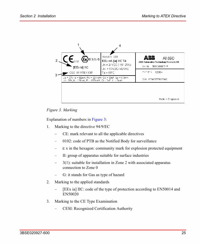
Marking to ATEX DirectiveThe modules has been designed as an associated apparatus to interface intrinsically safe or simple apparatus in hazardous areas and it could be installed in safe area or in Zone 2.
According to the requirements of the European directive 94/9/EC, apparatus shall be marked to show specific approval and the permitted areas of use, see Figure 3.
Section 2 Installation Marking to ATEX Directive
3BSE020927-600 25
Explanation of numbers in Figure 3:
1. Marking to the directive 94/9/EC
– CE: mark relevant to all the applicable directives
– 0102: code of PTB as the Notified Body for surveillance
– x in the hexagon: community mark for explosion protected equipment
– II: group of apparatus suitable for surface industries
– 3(1): suitable for installation in Zone 2 with associated apparatus connection to Zone 0
– G: it stands for Gas as type of hazard
2. Marking to the applied standards
– [EEx ia] IIC: code of the type of protection according to EN50014 and EN50020
3. Marking to the CE Type Examination
– CESI: Recognized Certification Authority
Figure 3. Marking
41
2
3
Marking to ATEX Directive Section 2 Installation
26 3BSE020927-600
– 01: year of issue
– ATEX: European directive
– 093: progressive number in the year
4. Marking to EN50021 standard
– EEx nA [ia] IIC T4: non sparking apparatus with intrinsically safe inputs
3BSE020927-600 27
Section 3 Configuration
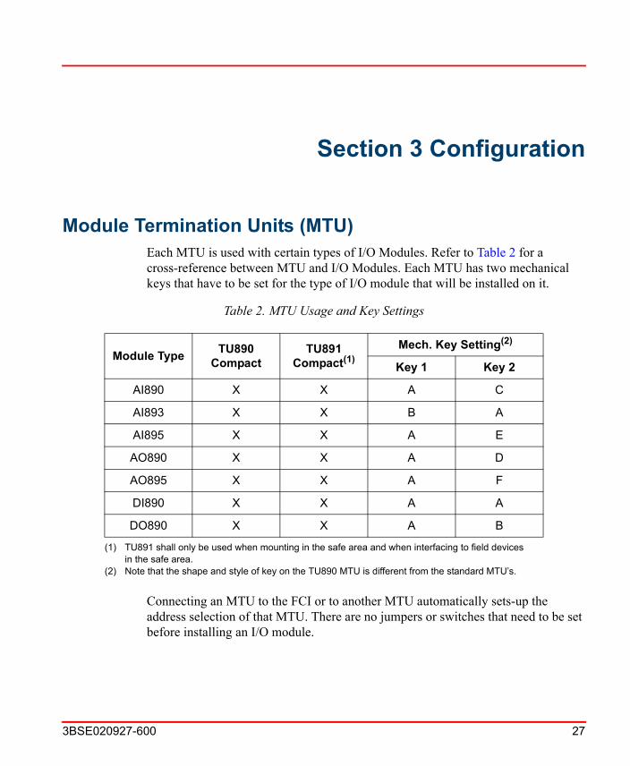
Module Termination Units (MTU)Each MTU is used with certain types of I/O Modules. Refer to Table 2 for a cross-reference between MTU and I/O Modules. Each MTU has two mechanical keys that have to be set for the type of I/O module that will be installed on it.
Connecting an MTU to the FCI or to another MTU automatically sets-up the address selection of that MTU. There are no jumpers or switches that need to be set before installing an I/O module.
Table 2. MTU Usage and Key Settings
Module TypeTU890
CompactTU891
Compact(1)
(1) TU891 shall only be used when mounting in the safe area and when interfacing to field devices in the safe area.
Mech. Key Setting(2)
(2) Note that the shape and style of key on the TU890 MTU is different from the standard MTU’s.
Key 1 Key 2
AI890 X X A C
AI893 X X B A
AI895 X X A E
AO890 X X A D
AO895 X X A F
DI890 X X A A
DO890 X X A B
I/O Modules Section 3 Configuration
28 3BSE020927-600
MTUs are placed on the DIN rails and then connected to the preceding MTU or FCI. Once connected, the MTU is locked in place by the bottom latch which also bonds it to the chassis ground.
I/O ModulesEach I/O module is installed onto an MTU. See Table 2 for which MTU to use with each I/O module type. I/O modules do not have any jumpers or switches that need to be set before installing on an MTU. Refer to Appendix A, Specifications for more information.
I/O modules are installed by aligning the connectors of the MTU and I/O module and then pushing the units together. After connected to the MTU, the I/O module is then locked in place by the I/O Module Lock/Switch which also activates a switch to enable power to the I/O module.
3BSE020927-600 29
Section 4 Maintenance
Preventive MaintenanceParticular attention should be paid to any safety regulations and regular visual inspection should be carried out of the safety element. For more information, Refer S800 I/O General Information and Installation (3BSE020923R5xxxx).
Hardware Indicators
I/O Module LEDs
Figure 4 shows examples of front panels for different types of I/O modules. On the front of each I/O module there are three LEDs (FAULT, RUN and WARNING) indicating the module status. One additional LED (OSP) is included on output modules. See Table 3 and Table 4 for information on the meaning and indications for these modules. For modules with special LED indications see the respective module in Appendix A, Specifications.
The FAULT LED shall indicate when the I/O module detect a fatal error or before first access after power up. The RUN LED shall indicate when the I/O module is operational. The WARNING LED shall indicate when a non-fatal error is detected and the module continues to run. The OSP LED shall indicate when the I/O module is commanded to OSP state or when the module detects that there is no communication to the module.
Each digital channel has one LED indicating current state (on/off) and one LED indicating channel fault.

Table 3. Standard LEDs on I/O Modules
Marking Color Description
F (Fault) Red Fault in the module (1)
(1) Modules without self test function, for example DI/DO modules: The F-LED will switch on at power up or restart of the module and switch off after the first successful access to the module.Modules with self test function for example, AI/AO modules: The F-LED will switch on at power up, restart of the module or when the module goes to Error state. If the module has not gone to Error state it will switch off the F-LED after the first successful access to the module.
R (Run) Green Operational state
W (Warning) Yellow External fault or minor fault in the module, that is, low process voltage
O (OSP) Yellow OSP state (Outputs Set as Predetermined)
Digital I/O on state Yellow Digital I/O signal on-state
Digital I/O fault Red Digital I/O channel line fault
I/O Module LEDs Section 4 Maintenance
30 3BSE020927-600
Table 4. I/O Module LED Indications in Different States
Module State Run Fault Warning OSP Signal status
Init Off On Off Off DI on/off, DO off
Not Configured Off On/Off (1)
(1) Will be switched off after the first successful access to the module.
On/Off Off DI on/off, DO off
Ready Off Off On/Off Off DI on/off, DO off
Operational On Off On/Off Off On/Off
OSP On Off On/Off On On/Off
Error Off On Off Off DI on/off, DO off

Section 4 Maintenance Error Messages
3BSE020927-600 31
Normally when an I/O module has been removed from the configuration, the FCI will do a restart of the module. The module will end up in the NOT CONFIGURED mode.
Error MessagesPlease see the relevant controller manuals.
Fault Finding and User Repair
I/O Module Replacement
General
All I/O modules can be exchanged on-line with the process power supply connected. This is possible because the module deactivates when the I/O module lock switch is turned to unlock.
Figure 4. Examples of I/O Module LED Locations

I/O Module Replacement Section 4 Maintenance
32 3BSE020927-600
It is important to understand the consequences of a module exchange on-line and how it affects the process. Replacement of an S800 I/O module affects all channels on the module. It also sometimes indirectly affects the outputs via some application function, on another module.
The system software in the FCI checks automatically that all I/O modules function correctly. In the event of module fault, and module exchange, the module and associated signals are marked as faulty.
The system software checks that the module is inserted and correct. If this is the case, the Fault indicator (LED) extinguishes (after 10 seconds), the fault marking in the data base is reset and the module resumes its normal function.
The following headings include general instructions for replacement of modules and aspects on the handling of individual modules are presented in Table 5.
Practical Execution
Replace faulty or suspect I/O modules in the following way:
1. Read S800 I/O General Information and Installation.
2. Special restrictions apply to each module type. See descriptions in Table 5 for useful information on individual module types.
3. Check that the new module can replace the old.
4. Provide access to the module by loosening the module locking.
5. Grip the module firmly and extract the module.
6. Insert the new module carefully.
7. Store extracted modules in envelopes.
8. Ensure that the module contacts mate properly with the contacts in the MTU and activate the locking mechanism in place.
9. Modules initialized automatically by the system and the fault indicating LED extinguishes automatically after approximately 10 seconds.
10. Perform a function test on the new module.
Section 4 Maintenance I/O Module Replacement
3BSE020927-600 33
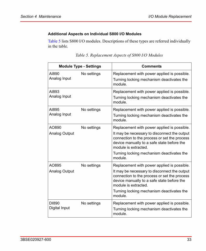
Additional Aspects on Individual S800 I/O Modules
Table 5 lists S800 I/O modules. Descriptions of these types are referred individually in the table.
Table 5. Replacement Aspects of S800 I/O Modules
Module Type - Settings Comments
AI890 Analog Input
No settings Replacement with power applied is possible.
Turning locking mechanism deactivates the module.
AI893Analog Input
Replacement with power applied is possible.
Turning locking mechanism deactivates the module.
AI895 Analog Input
No settings Replacement with power applied is possible.
Turning locking mechanism deactivates the module.
AO890
Analog Output
No settings Replacement with power applied is possible.
It may be necessary to disconnect the output connection to the process or set the process device manually to a safe state before the module is extracted.
Turning locking mechanism deactivates the module.
AO895
Analog Output
No settings Replacement with power applied is possible.
It may be necessary to disconnect the output connection to the process or set the process device manually to a safe state before the module is extracted.
Turning locking mechanism deactivates the module.
DI890Digital Input
No settings Replacement with power applied is possible.
Turning locking mechanism deactivates the module.

I/O Module Replacement Section 4 Maintenance
34 3BSE020927-600
DO890Digital Output
No settings Replacement with power applied is possible.
It may be necessary to disconnect the output connection to the process or set the process device manually to a safe state before the module is extracted.
Turning locking mechanism deactivates the module.
TU890 MTUs No settings Cannot be replaced or repaired with power applied.
Disconnecting an MTU breaks the ModuleBus communications bus and removes power to the MTUs that follow.
MTUs mounted in the middle (between the FCI and the number 12 MTU) need to have the preceding or following MTUs moved in order to disconnect the ModuleBus connector.
TU891 MTUs No settings Cannot be replaced or repaired with power applied.
Disconnecting an MTU breaks the ModuleBus communications bus and removes power to the MTUs that follow.
MTUs mounted in the middle (between the FCI and the number 12 MTU) need to have the preceding or following MTUs moved in order to disconnect the ModuleBus connector.
Observe all local requirements for working with signals into or from hazardous areas when removing or inserting modules under power.
Table 5. Replacement Aspects of S800 I/O Modules (Continued)
Module Type - Settings Comments
3BSE020927-600 35
Appendix A Specifications
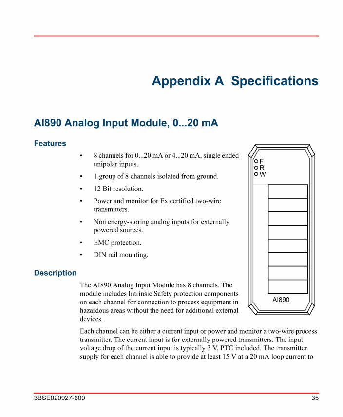
AI890 Analog Input Module, 0...20 mA
Features
FRW
AI890
• 8 channels for 0...20 mA or 4...20 mA, single ended unipolar inputs.
• 1 group of 8 channels isolated from ground.
• 12 Bit resolution.
• Power and monitor for Ex certified two-wire transmitters.
• Non energy-storing analog inputs for externally powered sources.
• EMC protection.
• DIN rail mounting.
Description
The AI890 Analog Input Module has 8 channels. The module includes Intrinsic Safety protection components on each channel for connection to process equipment in hazardous areas without the need for additional external devices.
Each channel can be either a current input or power and monitor a two-wire process transmitter. The current input is for externally powered transmitters. The input voltage drop of the current input is typically 3 V, PTC included. The transmitter supply for each channel is able to provide at least 15 V at a 20 mA loop current to
Description Appendix A Specifications
36 3BSE020927-600
power Ex certified process transmitters and is limited to 23 mA in overload conditions.
All eight channels are isolated from the ModuleBus and power supply in one group. Power to the input stages is converted from the 24 V on the power supply connections.
Three LEDs indicate module status Fault (Red), Run (Green) and Warning (Yellow). The RUN LED indicates normal operation and the WARNING LED indicates if any error input is active. The FAULT LED indicates that the module is in Init state or Not configured state. In Not configured state the FAULT LED is turned off after the first valid access to the module.
The reset circuitry gives a reset signal when the module is inserted until the BLOCK signal is inactive and the POWOK signal is active. The BLOCK signal is deactivated when the module lock mechanism is in the locked position. The POWOK comes from the FCI after power is applied.
TU890 and TU891 Compact MTU can be used with this module and it enables two wire connection to the process devices without additional terminals. TU890 for Ex applications and TU 891 for non Ex applications.

Appendix A Specifications Technical Data
3BSE020927-600 37
Technical Data
Table 6. AI890 Analog Input Module Specifications at 25C
FeatureAI890
Analog Input Module
Number of channels 8
Type of input Unipolar single ended
Measurement range 0...20 mA
Over/under range 0...22 mA
Available output voltage 15 V at 20 mA
Input voltage drop for current source 3 V typical
Maximum field cable length Defined by safety parameters
NMRR, 50 Hz, 60 Hz >20 dB
CMRR, 50 Hz, 60 Hz >80 dB
Error Max. 0.1%
Resolution 12 bit
Temperature drift Typ. 50 ppm/CMax. 100 ppm/C
Update cycle time 5 ms
Current consumption 24 V external Typ. 220 mA, Max. <300 mA
Current consumption 5 V Modulebus Typ. 70 mA, Max. 150 mA
Power dissipation 1.5 W
Maximum ambient temperature 55/40C (131/104F)(1)
Voltage supervision Internal process supply
Input filter (rise time) 75 ms
Isolation Group wise isolated from ground (RIV=50 V)

Technical Data Appendix A Specifications
38 3BSE020927-600
Mounting termination units TU890/TU891
MTU keying code AC
Safety classification Class I according to IEC 536; (earth protected)
Protection rating IP20 according to IEC 529, (IEC 144)
Rated insulation voltage 50 V
Dielectric test voltage 500 V a.c.
Width 45 mm (1.77”)
Depth 97 mm (3.8”), 106 mm (4.2”) including connector
Height 119 mm (4.7”)
Weight 0.2 kg (0.44 lbs.)
(1) 40C104F) applies to Compact MTUs with I/O modules mounted on a vertical DIN rail.
Table 6. AI890 Analog Input Module Specifications at 25C (Continued)
FeatureAI890
Analog Input Module
Appendix A Specifications Intrinsic Safety Parameters
3BSE020927-600 39
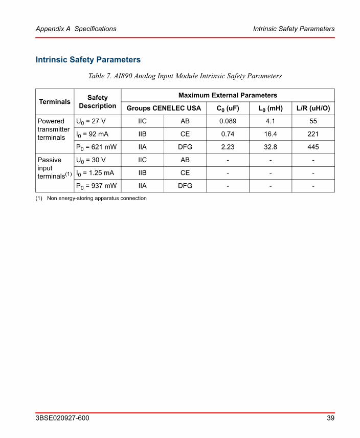
Intrinsic Safety Parameters
Table 7. AI890 Analog Input Module Intrinsic Safety Parameters
TerminalsSafety
Description
Maximum External Parameters
Groups CENELEC USA C0 (uF) L0 (mH) L/R (uH/O)
Powered transmitter terminals
U0 = 27 V IIC AB 0.089 4.1 55
I0 = 92 mA IIB CE 0.74 16.4 221
P0 = 621 mW IIA DFG 2.23 32.8 445
Passive input terminals(1)
(1) Non energy-storing apparatus connection
U0 = 30 V IIC AB - - -
I0 = 1.25 mA IIB CE - - -
P0 = 937 mW IIA DFG - - -
Block Diagram AI890 Appendix A Specifications
40 3BSE020927-600
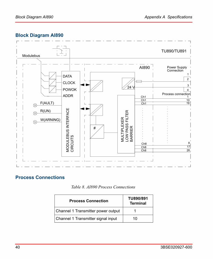
Block Diagram AI890
24 V
#
DATA
Modulebus
CLOCK
POWOK
ADDR
MO
DU
LEB
US
INT
ER
FAC
EC
IRC
UIT
S
MU
LTIP
LEX
ER
LOW
PA
SS
FIL
TE
RB
AR
RIE
R
AI890
TU890/TU891
W(ARNING)
R(UN)
F(AULT) Ch1Ch1Ch1
Ch8Ch8Ch8
Power SupplyConnection
26
1
8
4
3
2
17
19101
Process connection
Process Connections
Table 8. AI890 Process Connections
Process ConnectionTU890/891Terminal
Channel 1 Transmitter power output 1
Channel 1 Transmitter signal input 10

Appendix A Specifications Process Connections
3BSE020927-600 41
Channel 1 Current signal return 19
Channel 2 Transmitter power output 2
Channel 2 Transmitter signal input 11
Channel 2 Current signal return 20
Channel 3 Transmitter power output 3
Channel 3 Transmitter signal input 12
Channel 3 Current signal return 21
Channel 4 Transmitter power output 4
Channel 4 Transmitter signal input 13
Channel 4 Current signal return 22
Channel 5 Transmitter power output 5
Channel 5 Transmitter signal input 14
Channel 5 Current signal return 23
Channel 6 Transmitter power output 6
Channel 6 Transmitter signal input 15
Channel 6 Current signal return 24
Channel 7 Transmitter power output 7
Channel 7 Transmitter signal input 16
Channel 7 Current signal return 25
Channel 8 Transmitter power output 8
Channel 8 Transmitter signal input 17
Channel 8 Current signal return 26
Table 8. AI890 Process Connections (Continued)
Process ConnectionTU890/891Terminal

Process Connections Appendix A Specifications
42 3BSE020927-600
Figure 5. AI890 Connections
3 -WiresXMTRS
24 V
AI890
Ch1Ch1
12
34
TU890/891
+24 V
+0 V
24 V
MU
LTIP
LEX
ER
L
OW
PA
SS
FILT
ER
#
ProcessConnection
PowerSupplyConnection
BA
RR
IER
2 -WiresXMTRS
4 -WiresXMTRS
ZPCh2Ch2
ZPCh3Ch3
ZPCh4Ch4
ZPCh5Ch5
ZPCh6Ch6
ZPCh7Ch7
ZPCh8Ch8
ZP
110192
1120
312214
13225
14236
15247
16258
1726

Appendix A Specifications AI893 Analog Input Module, for RTD and TC sensors
3BSE020927-600 43
AI893 Analog Input Module, for RTD and TC sensors
Features
FRW
AI893
• 8 differential input channels for 2 or 3-wire RTD and Thermocouple.
• 1 group of 8 channels isolated from ground.
• 15 Bit + sign resolution.
• Ex certified inputs.
• EMC protection.
• DIN rail mounting.
• G3 compliant.
Description
The AI893 Analog Input Module has 8 channels. The module includes Intrinsic Safety protection components on each channel for connection to process equipment in hazardous areas without the need for additional external devices.
The module can be configured for either 2 or 3-wire RTD sensors or for TC sensors.
In TC mode, channel 8 be used for Cold Junction (ambient) temperature measurements, thus serving as CJ-channel for channel 1...7. The junction temperature may be measured locally on the MTUs screw terminals, or on a connection unit distant from the device. The cold junction temperature is measured with a 3-wire Pt 100 sensor. Alternatively, a fix junction temperature for the module may be set by the user (as parameter). Channel 8 may be used in the same manner as channel 1-7 when no CJ-temperature measurement is needed.
All eight channels are isolated from the ModuleBus and power supply in one group. Power to the input stages is converted from the 24 V on the power supply connections.

Description Appendix A Specifications
44 3BSE020927-600
Three LEDs indicate module status Fault (Red), Run (Green) and Warning (Yellow). The RUN LED indicates normal operation and the WARNING LED indicates if any error input is active. The FAULT LED indicates that the module is in Init state or Not configured state. In Not configured state the FAULT LED is turned off after the first valid access to the module.
The reset circuitry gives a reset signal when the module is inserted until the BLOCK signal is inactive and the POWOK signal is active. The BLOCK signal is deactivated when the module lock mechanism is in the locked position. The POWOK comes from the FCI or controller after power is applied.
TU890 and TU891 Compact MTU can be used with this module and it enables three wire connection to the process devices without additional terminals. TU890 for Ex applications and TU891 for non Ex applications.
Appendix A Specifications Technical Data
3BSE020927-600 45
Technical Data
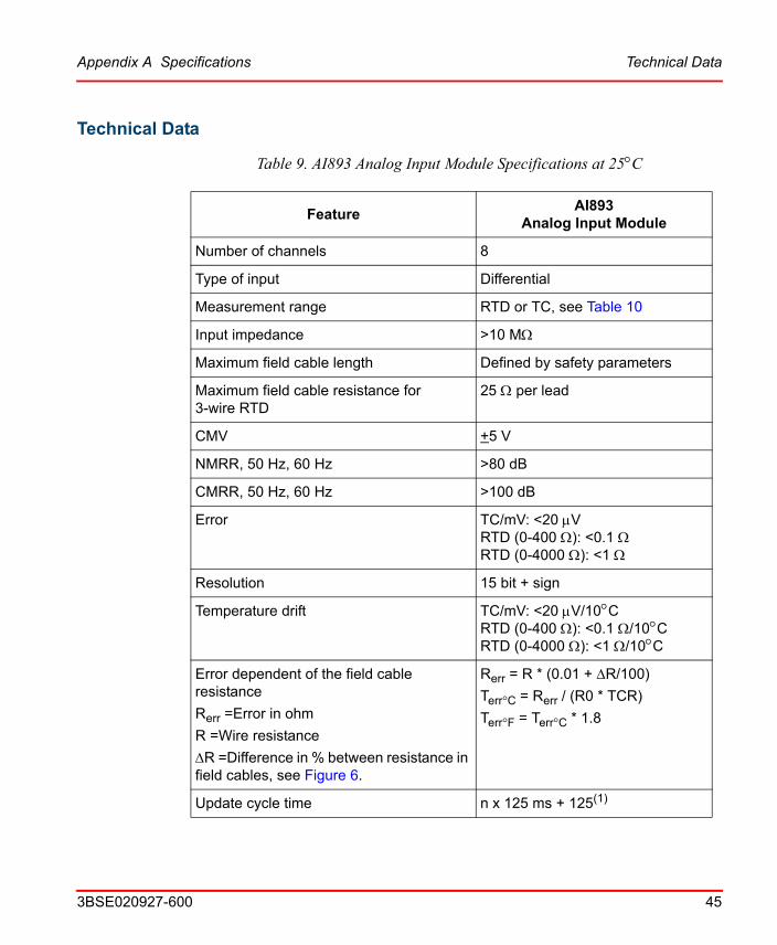
Table 9. AI893 Analog Input Module Specifications at 25C
FeatureAI893
Analog Input Module
Number of channels 8
Type of input Differential
Measurement range RTD or TC, see Table 10
Input impedance >10 M
Maximum field cable length Defined by safety parameters
Maximum field cable resistance for 3-wire RTD
25 per lead
CMV +5 V
NMRR, 50 Hz, 60 Hz >80 dB
CMRR, 50 Hz, 60 Hz >100 dB
Error TC/mV: <20 VRTD (0-400 ): <0.1 RTD (0-4000 ): <1
Resolution 15 bit + sign
Temperature drift TC/mV: <20 V/10CRTD (0-400 ): <0.1 /10CRTD (0-4000 ): <1 /10C
Error dependent of the field cable resistance
Rerr =Error in ohm
R =Wire resistance
R =Difference in % between resistance in field cables, see Figure 6.
Rerr = R * (0.01 + R/100)
Terr°C = Rerr / (R0 * TCR)
Terr°F = Terr°C * 1.8
Update cycle time n x 125 ms + 125(1)
Technical Data Appendix A Specifications
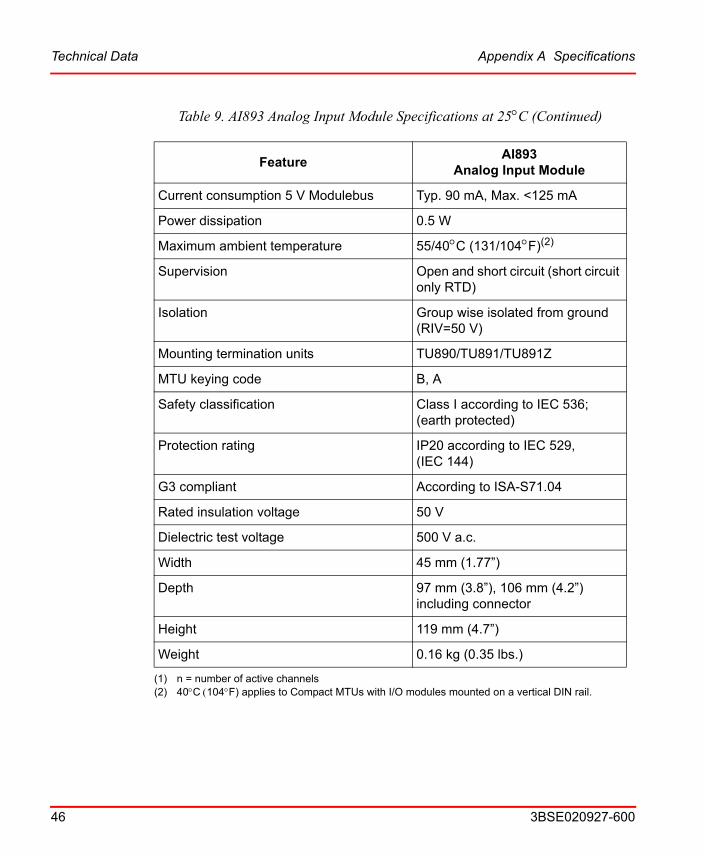
46 3BSE020927-600
Current consumption 5 V Modulebus Typ. 90 mA, Max. <125 mA
Power dissipation 0.5 W
Maximum ambient temperature 55/40C (131/104F)(2)
Supervision Open and short circuit (short circuit only RTD)
Isolation Group wise isolated from ground (RIV=50 V)
Mounting termination units TU890/TU891/TU891Z
MTU keying code B, A
Safety classification Class I according to IEC 536; (earth protected)
Protection rating IP20 according to IEC 529, (IEC 144)
G3 compliant According to ISA-S71.04
Rated insulation voltage 50 V
Dielectric test voltage 500 V a.c.
Width 45 mm (1.77”)
Depth 97 mm (3.8”), 106 mm (4.2”) including connector
Height 119 mm (4.7”)
Weight 0.16 kg (0.35 lbs.)
(1) n = number of active channels(2) 40C104F) applies to Compact MTUs with I/O modules mounted on a vertical DIN rail.
Table 9. AI893 Analog Input Module Specifications at 25C (Continued)
FeatureAI893
Analog Input Module

Appendix A Specifications Technical Data
3BSE020927-600 47
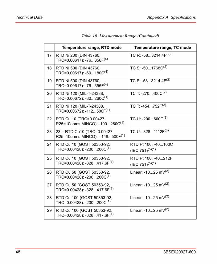
Table 10. Measurement Range
Temperature range, RTD mode Temperature range, TC mode
0 RTD Pt 50 (IEC 751): -200...850C(1) TC B: 44...1820C(2)
1 RTD Pt 50 (IEC 751): -328...1562F(1) TC B: 111.2...3308F(2)
2 RTD Pt 100 (IEC 751): -200...850C(1)(5) TC C: 0...2300C(3)
3 RTD Pt 100 (IEC 751): -328...1562F(1) TC C: 32...4172F(3)
4 RTD Pt 200 (IEC 751): -200...850C(4) TC D: 0...2300C(3)
5 RTD Pt 200 (IEC 751): -328...1562F(4) TC D: 32...4172F(3)
6 RTD Pt 500 (IEC 751): -200...850C(4) TC E: -270...1000C(3)
7 RTD Pt 500 (IEC 751): -328...1562F(4) TC E: -454...1832F(3)
8 RTD Pt 1000 (IEC 751): -200...850C(4) TC J: -210...1200C(3)
9 RTD Pt 1000 (IEC 751): -328...1562F(4) TC J: -346...2192F(3)
10 RTD Pt 50 (GOST 50353-92):-200...850C(1)
TC K: -270...1372C(3)
11 RTD Pt 50 (GOST 50353-92): -328...1562F(1)
TC K: -454...2501.6F(3)
12 RTD Pt 100 (GOST 50353-92): -200...850C(1)
TC L: -100...900C(3)
13 RTD Pt 100 (GOST 50353-92): -328...1562F(1)
TC L: -148...1652F(3)
14 RTD Ni 100 (DIN 43760, TRC=0.00617): -60...180C(1)
TC N: -270...1300C(3)
15 RTD Ni 100 (DIN 43760, TRC=0.00617): -76...356F(1)
TC N: -454...2372F(3)
16 RTD Ni 200 (DIN 43760, TRC=0.00617): -60...180C(4)
TC R: -50...1768C(2)
Technical Data Appendix A Specifications
48 3BSE020927-600
17 RTD Ni 200 (DIN 43760, TRC=0.00617): -76...356F(4)
TC R: -58...3214.4F(2)
18 RTD Ni 500 (DIN 43760, TRC=0.00617): -60...180C(4)
TC S: -50...1768C(2)
19 RTD Ni 500 (DIN 43760, TRC=0.00617): -76...356F(4)
TC S: -58...3214.4F(2)
20 RTD Ni 120 (MIL-T-24388, TRC=0.00672): -80...260C(1)
TC T: -270...400C(2)
21 RTD Ni 120 (MIL-T-24388, TRC=0.00672): -112...500F(1)
TC T: -454...752F(2)
22 RTD Cu 10 (TRC=0.00427, R25=10ohms MINCO): -100...260C(1)
TC U: -200...600C(3)
23 23 = RTD Cu10 (TRC=0.00427, R25=10ohms MINCO): - 148...500F(1)
TC U: -328...1112F(3)
24 RTD Cu 10 (GOST 50353-92, TRC=0.00428): -200...200C(1)
RTD Pt 100: -40...100C
(IEC 751)(5)(1)
25 RTD Cu 10 (GOST 50353-92, TRC=0.00428): -328...417.6F(1)
RTD Pt 100: -40...212F
(IEC 751)(5)(1)
26 RTD Cu 50 (GOST 50353-92, TRC=0.00428): -200...200C(1)
Linear: -10...25 mV(2)
27 RTD Cu 50 (GOST 50353-92, TRC=0.00428): -328...417.6F(1)
Linear: -10...25 mV(2)
28 RTD Cu 100 (GOST 50353-92, TRC=0.00428): -200...200C(1)
Linear: -10...25 mV(2)
29 RTD Cu 100 (GOST 50353-92, TRC=0.00428): -328...417.6F(1)
Linear: -10...25 mV(2)
Table 10. Measurement Range (Continued)
Temperature range, RTD mode Temperature range, TC mode

Appendix A Specifications Intrinsic Safety Parameters
3BSE020927-600 49
Intrinsic Safety Parameters
Table 11. AI893 Analog Input Module Intrinsic Safety Parameters
TerminalsSafety
Description
Maximum External Parameters
Groups CENELEC USA C0 (uF) L0 (mH) L/R (uH/O)
Input terminals
U0 = 12 V IIC AB 1.41 88 586
I0 = 20 mA IIB CE 9 352 2347
P0 = 60 mW IIA DFG 36 706 4707
30 Linear: 0...400 Ohm(1) Linear: -10...25 mV(2)
31 Linear: 0...4000 Ohm(4) Linear: -15...80 mV(3)
(1) Resolution 15 m(2) Resolution 1.5 V(3) Resolution 3 V(4) Resolution 150 m(5) Only at channel 8 and measured CJ.
Figure 6. Error dependency of the field cable resistance
Table 10. Measurement Range (Continued)
Temperature range, RTD mode Temperature range, TC mode
AI893R1
R2Pt100
R=Difference betweenR1 and R2
R1, R2, Rzp=Field cable
Rzp
resistance
Block Diagram AI893 Appendix A Specifications
50 3BSE020927-600
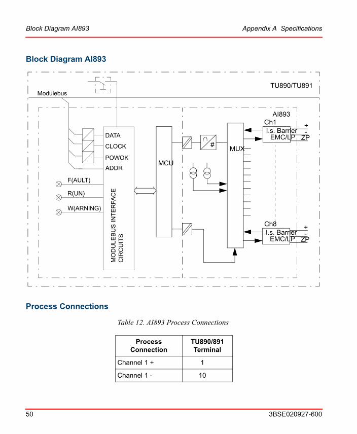
Block Diagram AI893
DATA
Modulebus
CLOCK
POWOK
ADDR
MO
DU
LEB
US
INT
ER
FA
CE
CIR
CU
ITS
TU890/TU891
W(ARNING)
R(UN)
F(AULT)
EMC/LP-+
MUX#
MCU
I.s. BarrierCh1
ZP
EMC/LP-+
I.s. BarrierCh8
ZP
AI893
Process Connections
Table 12. AI893 Process Connections
Process Connection
TU890/891Terminal
Channel 1 + 1
Channel 1 - 10

Appendix A Specifications Process Connections
3BSE020927-600 51
Channel 1 ZP 19
Channel 2 + 2
Channel 2 - 11
Channel 2 ZP 20
Channel 3 + 3
Channel 3 - 12
Channel 3 ZP 21
Channel 4 + 4
Channel 4 - 13
Channel 4 ZP 22
Channel 5 + 5
Channel 5 - 14
Channel 5 ZP 23
Channel 6 + 6
Channel 6 - 15
Channel 6 ZP 24
Channel 7 + 7
Channel 7 - 16
Channel 7 ZP 25
Channel 8 + 8
Channel 8 - 17
Channel 8 ZP 26
Table 12. AI893 Process Connections (Continued)
Process Connection
TU890/891Terminal
Process Connections Appendix A Specifications
52 3BSE020927-600
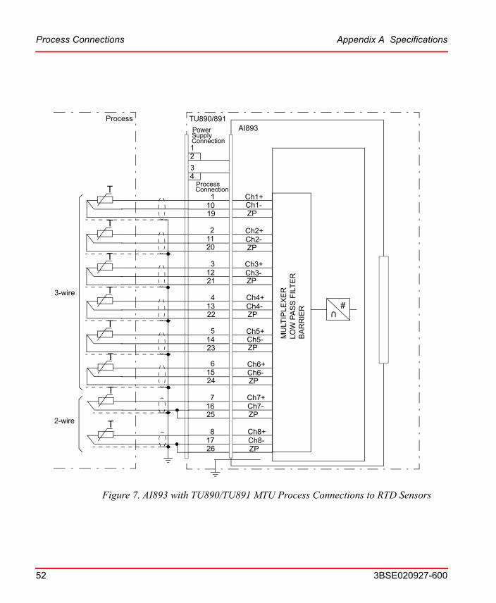
Figure 7. AI893 with TU890/TU891 MTU Process Connections to RTD Sensors
AI893
Ch1+Ch1-
12
34
TU890/891
MU
LTIP
LEX
ER
LO
W P
AS
S F
ILT
ER
#
Process
Power
Connection
BA
RR
IER
ZP
Ch2+Ch2-ZP
Ch3+Ch3-ZP
Ch5+Ch5-ZP
Ch6+Ch6-ZP
Ch7+Ch7-ZP
Ch8+Ch8-ZP
11019
21120
31221
51423
61524
71625
81726
T
T
T
T
T
T
T
Process
Ch4+Ch4-ZP
41322
T
Supply
Connection
U
2-wire
3-wire

Figure 8. AI893 with TU890/TU891 MTU Process Connections to TC Sensors
Appendix A Specifications Process Connections
3BSE020927-600 53
AI893
Ch1+Ch1-
12
34
TU890/891
MU
LTIP
LEX
ER
LO
W P
AS
S F
ILT
ER
#
Process
Power
Connection
BA
RR
IER
ZP
Ch2+Ch2-ZP
Ch3+Ch3-ZP
Ch5+Ch5-ZP
Ch6+Ch6-ZP
Ch7+Ch7-ZP
Ch8+Ch8-ZP
11019
21120
31221
51423
61524
71625
81726
T
Process
Ch4+Ch4-ZP
41322
Supply
Connection
U
Thermocouple isolatedfrom ground
Thermocouple connectedto ground

Figure 9. AI893 with TU890/TU891 MTU Process Connections to TC Sensors via Remote Junction Box
Process Connections Appendix A Specifications
54 3BSE020927-600
AI893
Ch1+Ch1-
12
34
TU890/891
MU
LTIP
LEX
ER
LO
W P
AS
S F
ILT
ER
#
Process
Power
Connection
BA
RR
IER
ZP
Ch2+Ch2-ZP
Ch3+Ch3-ZP
Ch5+Ch5-ZP
Ch6+Ch6-ZP
Ch7+Ch7-ZP
Ch8+Ch8-ZP
11019
21120
31221
51423
61524
71625
81726
T
Process
Ch4+Ch4-ZP
41322
Supply
Connection
U
Thermocouple isolatedfrom ground
Thermocouple connectedto ground
Junction Box
Appendix A Specifications AI895 Analog Input Module, 4...20 mA and HART
3BSE020927-600 55
AI895 Analog Input Module, 4...20 mA and HART
Features
FRW
AI895
Tx
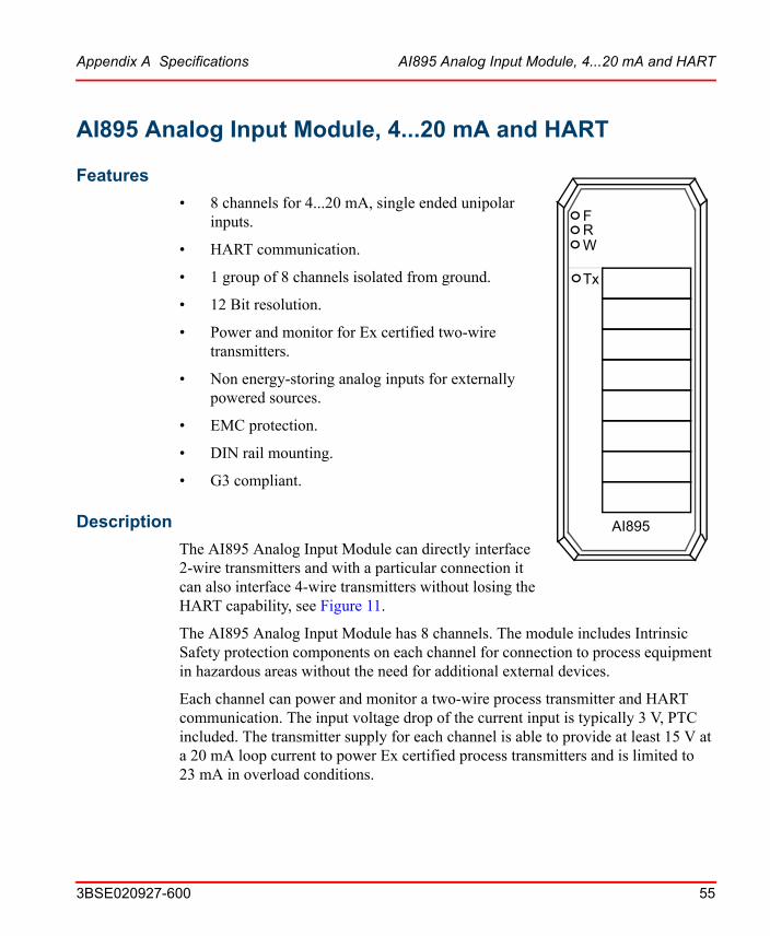
• 8 channels for 4...20 mA, single ended unipolar inputs.
• HART communication.
• 1 group of 8 channels isolated from ground.
• 12 Bit resolution.
• Power and monitor for Ex certified two-wire transmitters.
• Non energy-storing analog inputs for externally powered sources.
• EMC protection.
• DIN rail mounting.
• G3 compliant.
Description
The AI895 Analog Input Module can directly interface 2-wire transmitters and with a particular connection it can also interface 4-wire transmitters without losing the HART capability, see Figure 11.
The AI895 Analog Input Module has 8 channels. The module includes Intrinsic Safety protection components on each channel for connection to process equipment in hazardous areas without the need for additional external devices.
Each channel can power and monitor a two-wire process transmitter and HART communication. The input voltage drop of the current input is typically 3 V, PTC included. The transmitter supply for each channel is able to provide at least 15 V at a 20 mA loop current to power Ex certified process transmitters and is limited to 23 mA in overload conditions.
Description Appendix A Specifications
56 3BSE020927-600
All eight channels are isolated from the ModuleBus and power supply in one group. Power to the input stages is converted from the 24 V on the power supply connections.
Three LEDs indicate module status Fault (Red), Run (Green) and Warning (Yellow). The RUN LED indicates normal operation and the WARNING LED indicates if any error input is active. The FAULT LED indicates that the module is in Init state or Not configured state. In Not configured state the FAULT LED is turned off after the first valid access to the module.
The reset circuitry gives a reset signal when the module is inserted until the BLOCK signal is inactive and the POWOK signal is active. The BLOCK signal is deactivated when the module lock mechanism is in the locked position. The POWOK comes from the FCI after power is applied.
TU890 and TU891 Compact MTU can be used with this module and it enables two wire connection to the process devices without additional terminals. TU890 for Ex applications and TU891 for non Ex applications.
Appendix A Specifications Technical Data
3BSE020927-600 57
Technical Data
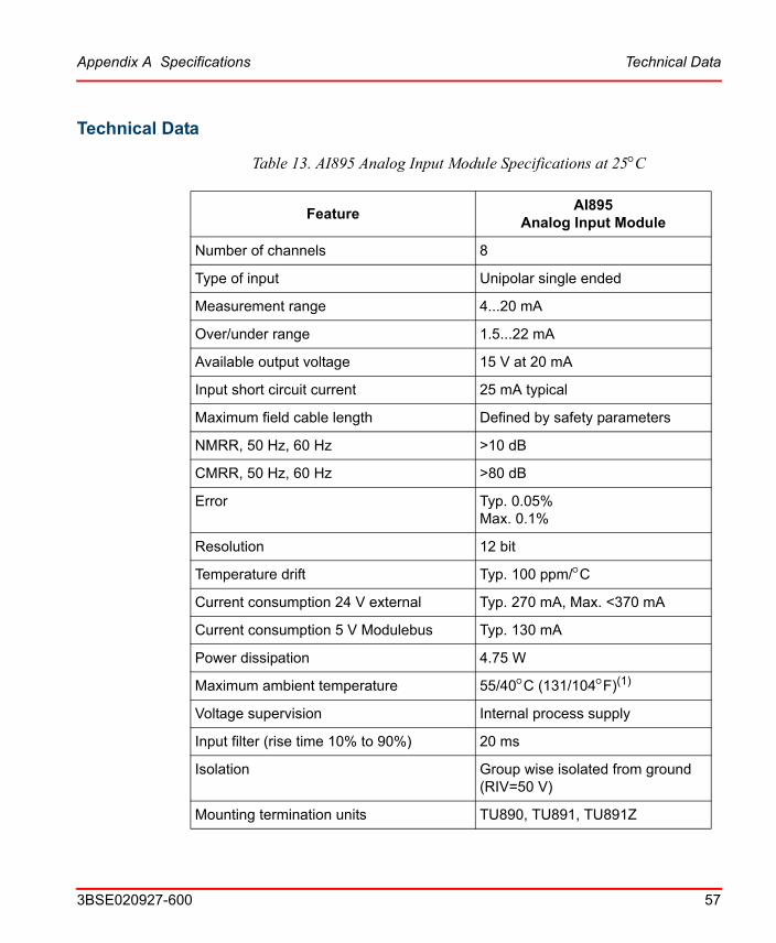
Table 13. AI895 Analog Input Module Specifications at 25C
FeatureAI895
Analog Input Module
Number of channels 8
Type of input Unipolar single ended
Measurement range 4...20 mA
Over/under range 1.5...22 mA
Available output voltage 15 V at 20 mA
Input short circuit current 25 mA typical
Maximum field cable length Defined by safety parameters
NMRR, 50 Hz, 60 Hz >10 dB
CMRR, 50 Hz, 60 Hz >80 dB
Error Typ. 0.05%Max. 0.1%
Resolution 12 bit
Temperature drift Typ. 100 ppm/C
Current consumption 24 V external Typ. 270 mA, Max. <370 mA
Current consumption 5 V Modulebus Typ. 130 mA
Power dissipation 4.75 W
Maximum ambient temperature 55/40C (131/104F)(1)
Voltage supervision Internal process supply
Input filter (rise time 10% to 90%) 20 ms
Isolation Group wise isolated from ground (RIV=50 V)
Mounting termination units TU890, TU891, TU891Z

Technical Data Appendix A Specifications
58 3BSE020927-600
MTU keying code AE
Safety classification Class I according to IEC 536; (earth protected)
Protection rating IP20 according to IEC 529, (IEC 144)
G3 compliant According to ISA-S71.04
Rated insulation voltage 50 V
Dielectric test voltage 500 V a.c.
Width 45 mm (1.77”)
Depth 97 mm (3.8”), 106 mm (4.2”) including connector
Height 119 mm (4.7”)
Weight 0.2 kg (0.44 lbs.)
(1) 40C104F) applies to Compact MTUs with I/O modules mounted on a vertical DIN rail.
Table 13. AI895 Analog Input Module Specifications at 25C (Continued)
FeatureAI895
Analog Input Module
Appendix A Specifications Intrinsic Safety Parameters
3BSE020927-600 59
Intrinsic Safety Parameters
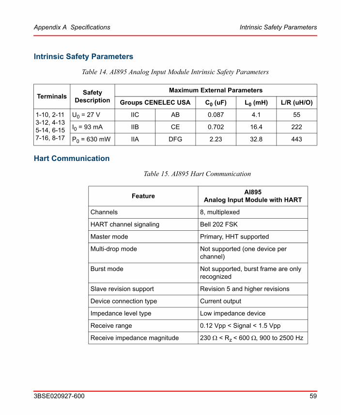
Table 14. AI895 Analog Input Module Intrinsic Safety Parameters
TerminalsSafety
Description
Maximum External Parameters
Groups CENELEC USA C0 (uF) L0 (mH) L/R (uH/O)
1-10, 2-113-12, 4-135-14, 6-157-16, 8-17
U0 = 27 V IIC AB 0.087 4.1 55
I0 = 93 mA IIB CE 0.702 16.4 222
P0 = 630 mW IIA DFG 2.23 32.8 443
Hart Communication
Table 15. AI895 Hart Communication
FeatureAI895
Analog Input Module with HART
Channels 8, multiplexed
HART channel signaling Bell 202 FSK
Master mode Primary, HHT supported
Multi-drop mode Not supported (one device per channel)
Burst mode Not supported, burst frame are only recognized
Slave revision support Revision 5 and higher revisions
Device connection type Current output
Impedance level type Low impedance device
Receive range 0.12 Vpp < Signal < 1.5 Vpp
Receive impedance magnitude 230 < Rz < 600 900 to 2500 Hz

Hart Communication Appendix A Specifications
60 3BSE020927-600
Carrier detect levels Signal > 120 mVpp, CD asserted
Signal < 80 mVpp, CD not asserted
Transmit signal amplitude 400 < Signal < 800, load 1 k
Table 15. AI895 Hart Communication (Continued)
FeatureAI895
Analog Input Module with HART
Appendix A Specifications Block Diagram AI895
3BSE020927-600 61
Block Diagram AI895
24 V
#
DATA
Modulebus
CLOCK
POWOK
ADDR
MO
DU
LEB
US
INT
ER
FAC
EC
IRC
UIT
S
MU
LTIP
LEX
ER
LOW
PA
SS
FIL
TE
RB
AR
RIE
R
AI895
TU890/TU891
W(ARNING)
R(UN)
F(AULT)Ch1Ch1
Ch8
Ch8
Power SupplyConnection
1
8
4
3
2
17
10
1Process connection
HA
RT
INT
ER
FAC
E
Process Connections
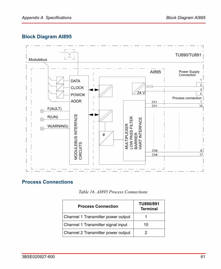
Table 16. AI895 Process Connections
Process ConnectionTU890/891Terminal
Channel 1 Transmitter power output 1
Channel 1 Transmitter signal input 10
Channel 2 Transmitter power output 2

Process Connections Appendix A Specifications
62 3BSE020927-600
Channel 2 Transmitter signal input 11
Channel 3 Transmitter power output 3
Channel 3 Transmitter signal input 12
Channel 4 Transmitter power output 4
Channel 4 Transmitter signal input 13
Channel 5 Transmitter power output 5
Channel 5 Transmitter signal input 14
Channel 6 Transmitter power output 6
Channel 6 Transmitter signal input 15
Channel 7 Transmitter power output 7
Channel 7 Transmitter signal input 16
Channel 8 Transmitter power output 8
Channel 8 Transmitter signal input 17
Table 16. AI895 Process Connections (Continued)
Process ConnectionTU890/891Terminal

Figure 10. AI895 Connection of 2-Wires Transmitter
Appendix A Specifications Process Connections
3BSE020927-600 63
Ch211
24 V
AI895
Ch8Ch8
Ch1Ch1
312
12
34
TU890/891
+24 V
+0 V
Ch2
Ch3Ch3Ch4
Ch7
Ch6
2
110
514
413
615716817
Ch4Ch5Ch5
Ch7
Ch6
24 V
MU
LTIP
LEX
ER
LO
W P
AS
S F
ILTE
R
#
ProcessConnection
PowerSupply
Connection
BA
RR
IER
2-WiresXMTRS
2-WiresXMTRS
HA
RT
INT
ER
FAC
E

Figure 11. AI895 Connection of 4-Wires Transmitter
Process Connections Appendix A Specifications
64 3BSE020927-600
Please observe the following requirements:
• The 4-wire transmitter must have the analog output (4-20 mA) isolated from its power supply.
• The 4-wire transmitter must have the analog output with a load capability > 550 ohms (> 11 V) at 20 mA.
• Connection polarity must be observed as in Figure 11 (it is different to the standard 2-wire connection).
Ch211
24 V
AI895
Ch8Ch8
Ch1Ch1
312
12
34
TU890/891
+24 V
+0 V
Ch2
Ch3Ch3Ch4
Ch7
Ch6
2
110
514
413
615716817
Ch4Ch5Ch5
Ch7
Ch6
24 V
MU
LTIP
LEX
ER
LO
W P
AS
S F
ILTE
R
#
ProcessConnection
PowerSupply
Connection
BA
RR
IER
4-WiresXMTRS
HA
RT
INT
ER
FAC
E+
-
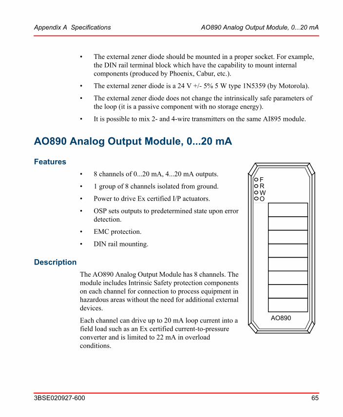
Appendix A Specifications AO890 Analog Output Module, 0...20 mA
3BSE020927-600 65
• The external zener diode should be mounted in a proper socket. For example, the DIN rail terminal block which have the capability to mount internal components (produced by Phoenix, Cabur, etc.).
• The external zener diode is a 24 V +/- 5% 5 W type 1N5359 (by Motorola).
• The external zener diode does not change the intrinsically safe parameters of the loop (it is a passive component with no storage energy).
• It is possible to mix 2- and 4-wire transmitters on the same AI895 module.
AO890 Analog Output Module, 0...20 mA
Features
FRW
AO890
O
• 8 channels of 0...20 mA, 4...20 mA outputs.
• 1 group of 8 channels isolated from ground.
• Power to drive Ex certified I/P actuators.
• OSP sets outputs to predetermined state upon error detection.
• EMC protection.
• DIN rail mounting.
Description
The AO890 Analog Output Module has 8 channels. The module includes Intrinsic Safety protection components on each channel for connection to process equipment in hazardous areas without the need for additional external devices.
Each channel can drive up to 20 mA loop current into a field load such as an Ex certified current-to-pressure converter and is limited to 22 mA in overload conditions.
Description Appendix A Specifications
66 3BSE020927-600
All eight channels are isolated from the ModuleBus and power supply in one group. Power to the output stages is converted from the 24 V on the power supply connections.
Four LEDs indicate module status Fault (Red), Run (Green), OSP (Yellow) and Warning (Yellow). The RUN LED indicates normal operation and the WARNING LED indicates if any error input is active. The FAULT LED indicates that the module is in Init state or Not configured state. In Not configured state the FAULT LED is turned off after the first valid access to the module. The OSP LED is turned on when the output is set to the predetermined OSP value.
The module performs self-diagnostic checks cyclically. Module diagnostics include: Process power supply supervision which is reported when supply voltage to the output circuitry is too low. This error is reported but the module will continue to function within the power supply limits because the output current is supervised. Channel diagnostics include: Fault detection of the channel (only reported on active channels). Open circuit of the field wiring is only detected if the output set is greater than 1 mA.
The outputs of the module will be set to a predetermined value if the OSP-watchdog timer expires or ordered by the FCI. The watchdog timer which is in the range 256ms-1024ms is used for modulebus supervision. Three different values are possible, 256, 512 and 1024ms. The watchdog timer can also be disabled, which is the default after reset or power-up. The watchdog timer is re-triggered every time the correct node address has been decoded (or broadcast). If the watchdog timer expires or if the SetOSPState command is received, the module enters the OSP state and the active outputs (if any) are set to their OSP values which can be configured as a predefined value or to the last good value sent.
The output values will be kept as long as the module stays in the OSP state. To change the outputs the module first has to leave this state. This is done with an explicit command or if the BLOCK or POWOK signal is activated. When reentering Operational State, the outputs are still kept within their OSP value until new valid values are written.
The reset circuitry gives a reset signal when the module is inserted until the BLOCK signal is inactive and the POWOK signal is active. The BLOCK signal is deactivated when the module lock mechanism is in the locked position. The POWOK comes from the FCI after power is applied.
Appendix A Specifications Description
3BSE020927-600 67
TU890 and TU891 Compact MTU can be used with this module and it enables two wire connection to the process devices without additional terminals. TU890 for Ex applications and TU891 for non Ex applications.

Technical Data Appendix A Specifications
68 3BSE020927-600
Technical Data
Table 17. AO890 Analog Output Module Specifications at 25C
FeatureAO890
Analog Output Module
Number of channels 8
Type of output Unipolar single ended
Output range 0(4)...20 mA(1)
Over/under range 0...22 mA(1)
Output load(2) <725 ohms at 20 mA, no over-range
<625 ohms at up to 22 mA
Load effect factor Max. 0.1% from 0 to 725 ohms
Maximum field cable length Defined by safety parameters
Error Typ. 0.05%Max. 0.1% at 650 ohms
Resolution 12 bit
Output Set as Predetermined (OSP) timer 256, 512, 1024 ms
Temperature drift Typ. 50 ppm/CMax. 100 ppm/C
Step response time
10% to 90%
1 ms
Current consumption 24 V external Typ. 220 mA, Max. <300 mA
Current consumption 5 V Modulebus Typ. 110 mA , Max. <150 mA
Power dissipation (3) 3.1 W
Maximum ambient temperature 55/40C (131/104F)(4)
Voltage supervision Internal process supply
Open wire detection If output is set to > 1mA.
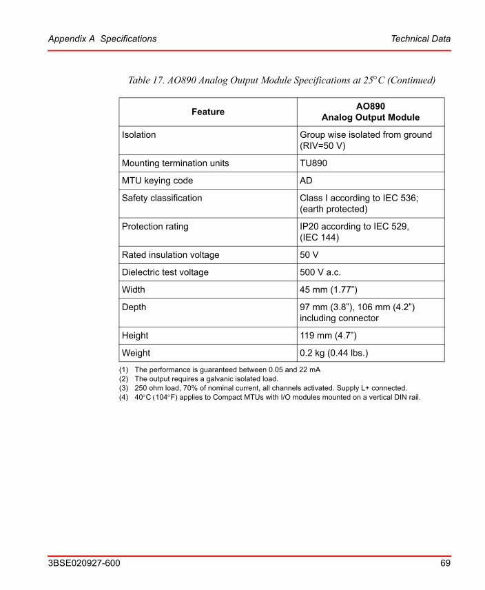
Appendix A Specifications Technical Data
3BSE020927-600 69
Isolation Group wise isolated from ground (RIV=50 V)
Mounting termination units TU890
MTU keying code AD
Safety classification Class I according to IEC 536; (earth protected)
Protection rating IP20 according to IEC 529, (IEC 144)
Rated insulation voltage 50 V
Dielectric test voltage 500 V a.c.
Width 45 mm (1.77”)
Depth 97 mm (3.8”), 106 mm (4.2”) including connector
Height 119 mm (4.7”)
Weight 0.2 kg (0.44 lbs.)
(1) The performance is guaranteed between 0.05 and 22 mA(2) The output requires a galvanic isolated load.(3) 250 ohm load, 70% of nominal current, all channels activated. Supply L+ connected.(4) 40C104F) applies to Compact MTUs with I/O modules mounted on a vertical DIN rail.
Table 17. AO890 Analog Output Module Specifications at 25C (Continued)
FeatureAO890
Analog Output Module
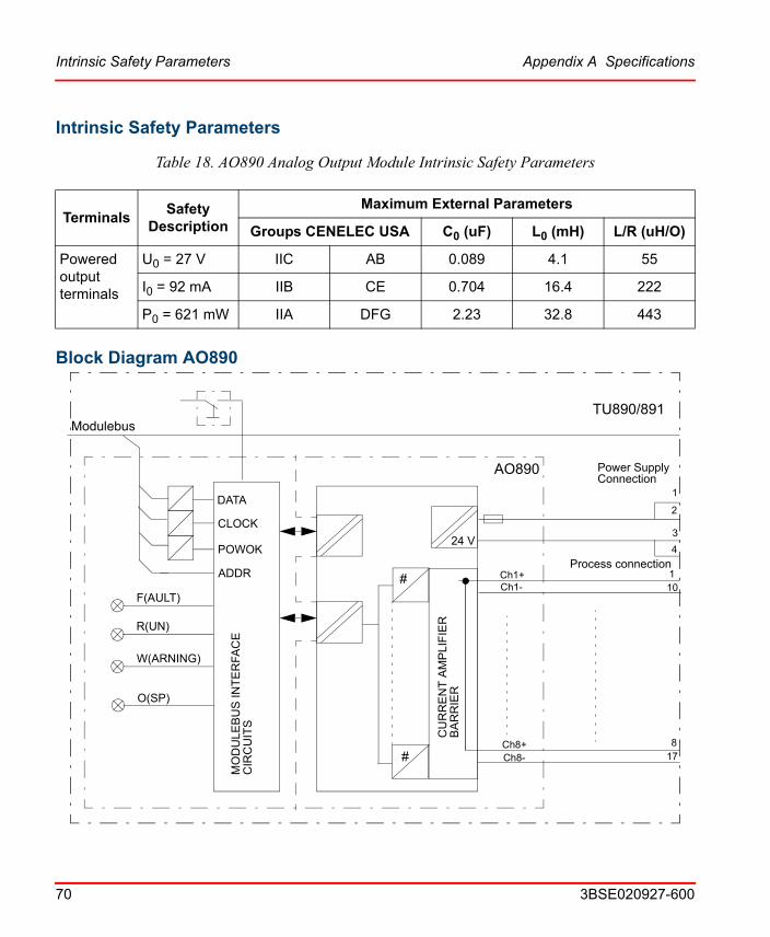
Intrinsic Safety Parameters Appendix A Specifications
70 3BSE020927-600
Intrinsic Safety Parameters
Table 18. AO890 Analog Output Module Intrinsic Safety Parameters
TerminalsSafety
Description
Maximum External Parameters
Groups CENELEC USA C0 (uF) L0 (mH) L/R (uH/O)
Powered output terminals
U0 = 27 V IIC AB 0.089 4.1 55
I0 = 92 mA IIB CE 0.704 16.4 222
P0 = 621 mW IIA DFG 2.23 32.8 443
Block Diagram AO890
24 V
DATA
Modulebus
CLOCK
POWOK
ADDR
MO
DU
LEB
US
INT
ER
FAC
EC
IRC
UIT
S
CU
RR
EN
T A
MP
LIF
IER
BA
RR
IER
AO890
TU890/891
W(ARNING)
R(UN)
F(AULT)Ch1-Ch1+
Ch8+Ch8-
O(SP)
#
#
Power SupplyConnection
1
8
4
3
2
17
101
Process connection
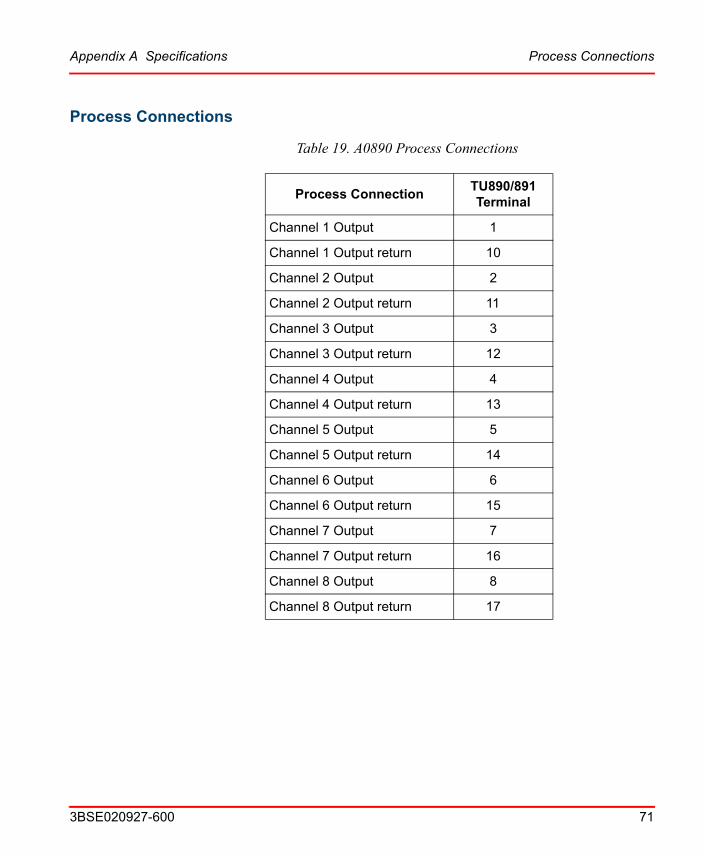
Appendix A Specifications Process Connections
3BSE020927-600 71
Process Connections
Table 19. A0890 Process Connections
Process ConnectionTU890/891Terminal
Channel 1 Output 1
Channel 1 Output return 10
Channel 2 Output 2
Channel 2 Output return 11
Channel 3 Output 3
Channel 3 Output return 12
Channel 4 Output 4
Channel 4 Output return 13
Channel 5 Output 5
Channel 5 Output return 14
Channel 6 Output 6
Channel 6 Output return 15
Channel 7 Output 7
Channel 7 Output return 16
Channel 8 Output 8
Channel 8 Output return 17
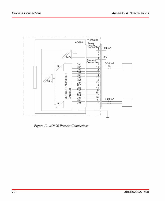
Figure 12. AO890 Process Connections
Process Connections Appendix A Specifications
72 3BSE020927-600
Ch2 11
24 V
AO890
Ch8Ch8
Ch1Ch1
312
12
34
TU890/891
+ 24 mA
+0 V
Ch2
Ch3Ch3Ch4
Ch7
Ch6
2
110
514
413
615
7168
17
Ch4Ch5Ch5
Ch7
Ch6
24 V
CU
RR
EN
T A
MP
LIF
IER
BA
RR
IER
#
#
0-20 mA
0-20 mA
ProcessConnection
PowerSupplyConnection
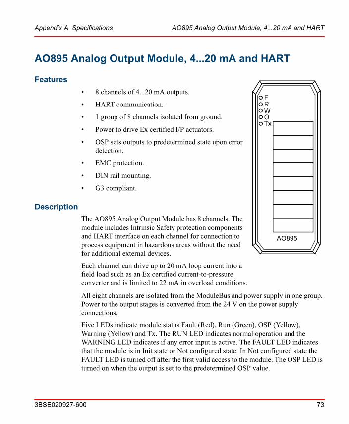
Appendix A Specifications AO895 Analog Output Module, 4...20 mA and HART
3BSE020927-600 73
AO895 Analog Output Module, 4...20 mA and HART
Features
FRW
AO895
OTx
• 8 channels of 4...20 mA outputs.
• HART communication.
• 1 group of 8 channels isolated from ground.
• Power to drive Ex certified I/P actuators.
• OSP sets outputs to predetermined state upon error detection.
• EMC protection.
• DIN rail mounting.
• G3 compliant.
Description
The AO895 Analog Output Module has 8 channels. The module includes Intrinsic Safety protection components and HART interface on each channel for connection to process equipment in hazardous areas without the need for additional external devices.
Each channel can drive up to 20 mA loop current into a field load such as an Ex certified current-to-pressure converter and is limited to 22 mA in overload conditions.
All eight channels are isolated from the ModuleBus and power supply in one group. Power to the output stages is converted from the 24 V on the power supply connections.
Five LEDs indicate module status Fault (Red), Run (Green), OSP (Yellow), Warning (Yellow) and Tx. The RUN LED indicates normal operation and the WARNING LED indicates if any error input is active. The FAULT LED indicates that the module is in Init state or Not configured state. In Not configured state the FAULT LED is turned off after the first valid access to the module. The OSP LED is turned on when the output is set to the predetermined OSP value.
Description Appendix A Specifications
74 3BSE020927-600
The module performs self-diagnostic checks cyclically. Module diagnostics include: Process power supply supervision which is reported when supply voltage to the output circuitry is too low. This error is reported but the module will continue to function within the power supply limits because the output current is supervised. Channel diagnostics include: Fault detection of the channel (only reported on active channels). Open circuit of the field wiring is only detected if the output set is greater than 1 mA.
The outputs of the module will be set to a predetermined value if the OSP-watchdog timer expires or ordered by the FCI. The watchdog timer which is in the range 256ms-1024ms is used for modulebus supervision. Three different values are possible, 256, 512 and 1024ms. The watchdog timer can also be disabled, which is the default after reset or power-up. The watchdog timer is re-triggered every time the correct node address has been decoded (or broadcast). If the watchdog timer expires or if the SetOSPState command is received, the module enters the OSP state and the active outputs (if any) are set to their OSP values which can be configured as a predefined value or to the last good value sent.
The output values will be kept as long as the module stays in the OSP state. To change the outputs the module first has to leave this state. This is done with an explicit command or if the BLOCK or POWOK signal is activated. When reentering Operational State, the outputs are still kept within their OSP value until new valid values are written.
The reset circuitry gives a reset signal when the module is inserted until the BLOCK signal is inactive and the POWOK signal is active. The BLOCK signal is deactivated when the module lock mechanism is in the locked position. The POWOK comes from the FCI after power is applied.
TU890 and TU891 Compact MTU can be used with this module and it enables two wire connection to the process devices without additional terminals. TU890 for Ex applications and TU891 for non Ex applications.
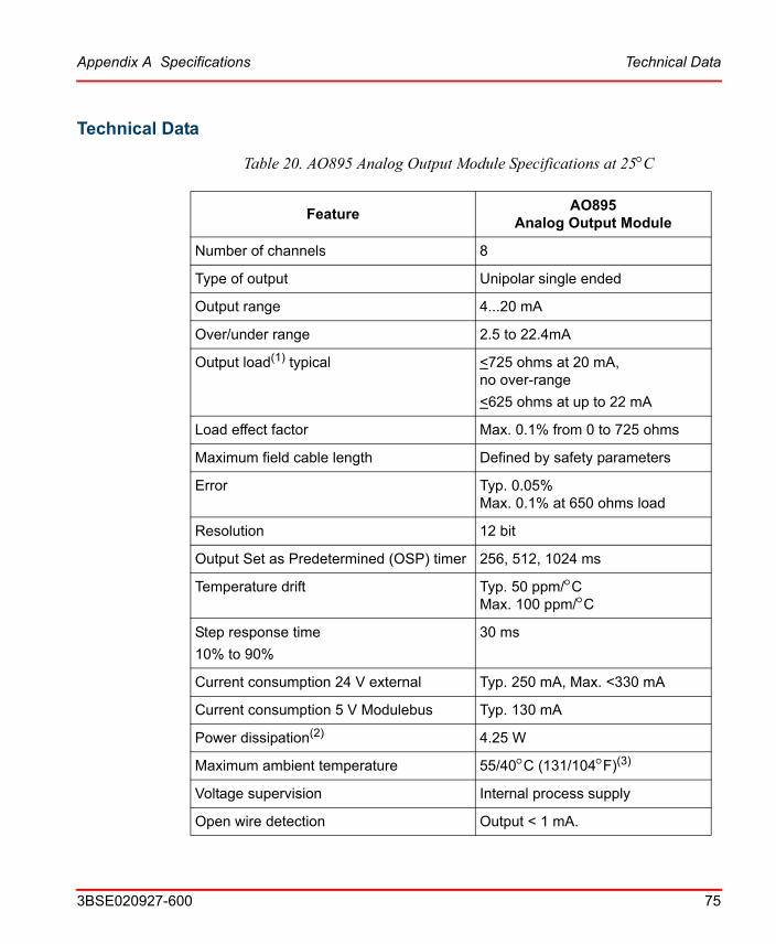
Appendix A Specifications Technical Data
3BSE020927-600 75
Technical Data
Table 20. AO895 Analog Output Module Specifications at 25C
FeatureAO895
Analog Output Module
Number of channels 8
Type of output Unipolar single ended
Output range 4...20 mA
Over/under range 2.5 to 22.4mA
Output load(1) typical <725 ohms at 20 mA, no over-range
<625 ohms at up to 22 mA
Load effect factor Max. 0.1% from 0 to 725 ohms
Maximum field cable length Defined by safety parameters
Error Typ. 0.05%Max. 0.1% at 650 ohms load
Resolution 12 bit
Output Set as Predetermined (OSP) timer 256, 512, 1024 ms
Temperature drift Typ. 50 ppm/CMax. 100 ppm/C
Step response time
10% to 90%
30 ms
Current consumption 24 V external Typ. 250 mA, Max. <330 mA
Current consumption 5 V Modulebus Typ. 130 mA
Power dissipation(2) 4.25 W
Maximum ambient temperature 55/40C (131/104F)(3)
Voltage supervision Internal process supply
Open wire detection Output < 1 mA.
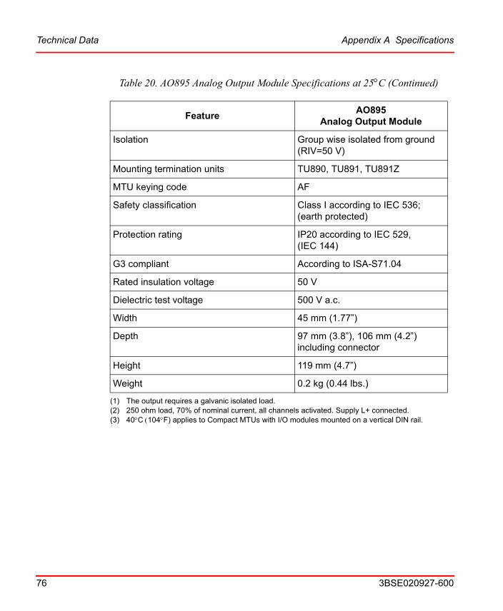
Technical Data Appendix A Specifications
76 3BSE020927-600
Isolation Group wise isolated from ground (RIV=50 V)
Mounting termination units TU890, TU891, TU891Z
MTU keying code AF
Safety classification Class I according to IEC 536; (earth protected)
Protection rating IP20 according to IEC 529, (IEC 144)
G3 compliant According to ISA-S71.04
Rated insulation voltage 50 V
Dielectric test voltage 500 V a.c.
Width 45 mm (1.77”)
Depth 97 mm (3.8”), 106 mm (4.2”) including connector
Height 119 mm (4.7”)
Weight 0.2 kg (0.44 lbs.)
(1) The output requires a galvanic isolated load.(2) 250 ohm load, 70% of nominal current, all channels activated. Supply L+ connected.(3) 40C104F) applies to Compact MTUs with I/O modules mounted on a vertical DIN rail.
Table 20. AO895 Analog Output Module Specifications at 25C (Continued)
FeatureAO895
Analog Output Module

Table 21. AO895 Hart Communication
FeatureAO895
Analog Output Module with HART
Channels 8, multiplexed
HART channel signaling Bell 202 FSK
Master mode Primary
Multi-drop mode Not supported (one device per channel)
Burst mode Not supported, burst frame are only recognized
Slave revision support Revision 5 and higher revisions
Device connection type Current output
Impedance level type High impedance device
Receive range 0.12 Vpp < Signal < 1.5 Vpp
Receive impedance magnitude > 50 k900 to 2500 Hz
Carrier detect levels Signal > 120 mVpp, CD asserted
Signal < 80 mVpp, CD not asserted
Transmit signal amplitude 400 < Signal < 600, load 500
Appendix A Specifications Hart Communication
3BSE020927-600 77
Hart Communication

Intrinsic Safety Parameters Appendix A Specifications
78 3BSE020927-600
Intrinsic Safety Parameters
Table 22. AO895 Analog Output Module Intrinsic Safety Parameters
TerminalsSafety
Description
Maximum External Parameters
Groups CENELEC USA C0 (uF) L0 (mH) L/R (uH/O)
Powered output terminals
U0 = 27 V IIC AB 0.087 4.1 55
I0 = 93 mA IIB CE 0.702 16.4 222
P0 = 630 mW IIA DFG 2.23 32.8 443
Block Diagram AO895
24 V
DATA
Modulebus
CLOCK
POWOK
ADDR
MO
DU
LE
BU
S IN
TE
RFA
CE
CIR
CU
ITS
CU
RR
EN
T A
MP
LIF
IER
BA
RR
IER
AO895
TU890/891
W(ARNING)
R(UN)
F(AULT)Ch1Ch1
Ch8Ch8
O(SP)
#
#
Power SupplyConnection
1
8
4
3
2
17
101
Process connection
HA
RT
IN
TE
RFA
CE

Appendix A Specifications Process Connections
3BSE020927-600 79
Process Connections
Table 23. A0895 Process Connections
Process ConnectionTU890/891Terminal
Channel 1 Output 1
Channel 1 Output return 10
Channel 2 Output 2
Channel 2 Output return 11
Channel 3 Output 3
Channel 3 Output return 12
Channel 4 Output 4
Channel 4 Output return 13
Channel 5 Output 5
Channel 5 Output return 14
Channel 6 Output 6
Channel 6 Output return 15
Channel 7 Output 7
Channel 7 Output return 16
Channel 8 Output 8
Channel 8 Output return 17

Figure 13. AO895 Process Connections
Process Connections Appendix A Specifications
80 3BSE020927-600
Ch2 11
24 V
AO895
Ch8Ch8
Ch1Ch1
312
12
34
TU890/891
+24 V
+0 V
Ch2
Ch3Ch3Ch4
Ch7
Ch6
2
110
514
413
615
7168
17
Ch4Ch5Ch5
Ch7
Ch6
24 V
CU
RR
EN
T A
MP
LIF
IER
BA
RR
IER
#
#
4-20 mA
4-20 mA
ProcessConnection
PowerSupplyConnection
HA
RT
INT
ER
FAC
E
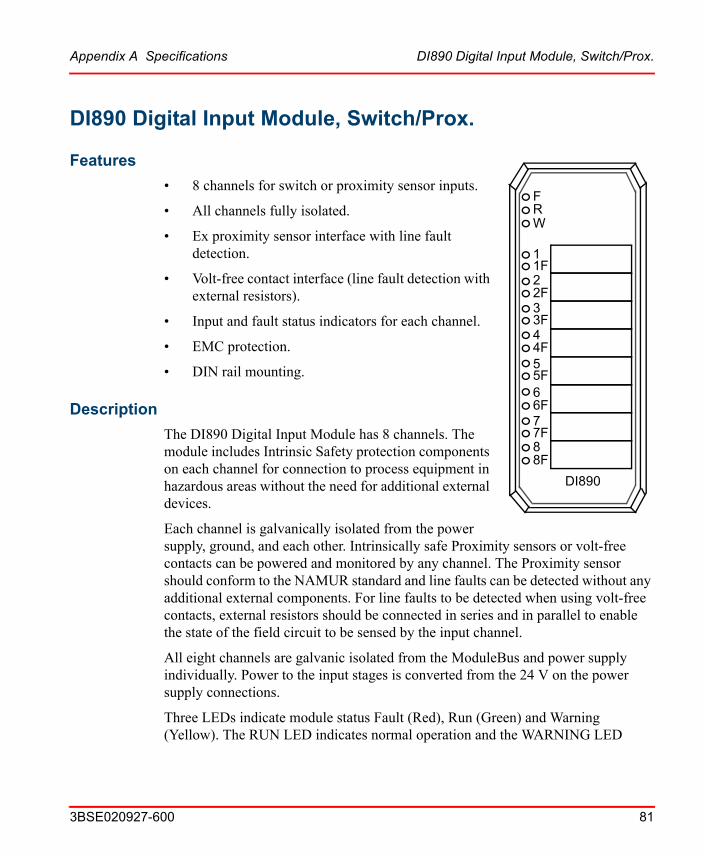
Appendix A Specifications DI890 Digital Input Module, Switch/Prox.
3BSE020927-600 81
DI890 Digital Input Module, Switch/Prox.
Features
6
7
8
FRW
1
2
3
4
5
DI890
8F
7F
6F
5F
4F
3F
2F
1F
• 8 channels for switch or proximity sensor inputs.
• All channels fully isolated.
• Ex proximity sensor interface with line fault detection.
• Volt-free contact interface (line fault detection with external resistors).
• Input and fault status indicators for each channel.
• EMC protection.
• DIN rail mounting.
Description
The DI890 Digital Input Module has 8 channels. The module includes Intrinsic Safety protection components on each channel for connection to process equipment in hazardous areas without the need for additional external devices.
Each channel is galvanically isolated from the power supply, ground, and each other. Intrinsically safe Proximity sensors or volt-free contacts can be powered and monitored by any channel. The Proximity sensor should conform to the NAMUR standard and line faults can be detected without any additional external components. For line faults to be detected when using volt-free contacts, external resistors should be connected in series and in parallel to enable the state of the field circuit to be sensed by the input channel.
All eight channels are galvanic isolated from the ModuleBus and power supply individually. Power to the input stages is converted from the 24 V on the power supply connections.
Three LEDs indicate module status Fault (Red), Run (Green) and Warning (Yellow). The RUN LED indicates normal operation and the WARNING LED

Description Appendix A Specifications
82 3BSE020927-600
indicates if any error input is active. The FAULT LED indicates that the module is in Init state or Not configured state. In Not configured state the FAULT LED is turned off after the first valid access to the module.
In addition there are two LEDs for each channel to show CHANNEL STATE (Yellow) (On = 1 and Off = 0) and CHANNEL FAULT (Red). The channel fault indication can be disabled when not required.
The reset circuitry gives a reset signal when the module is inserted until the BLOCK signal is inactive and the POWOK signal is active. The BLOCK signal is deactivated when the module lock mechanism is in the locked position. The POWOK comes from the FCI after power is applied.
The input channels can be digitally filtered. The different filter times that can be achieved are 2, 4, 8 and 16ms. This means that noise pulses shorter than the filter time will not be registered and pulses longer than 3, 6, 12 and 24ms will get through the filter.
TU890 and TU891 Compact MTU can be used with this module and it enables two wire connection to the process devices without additional terminals. TU890 for Ex applications and TU891 for non Ex applications.
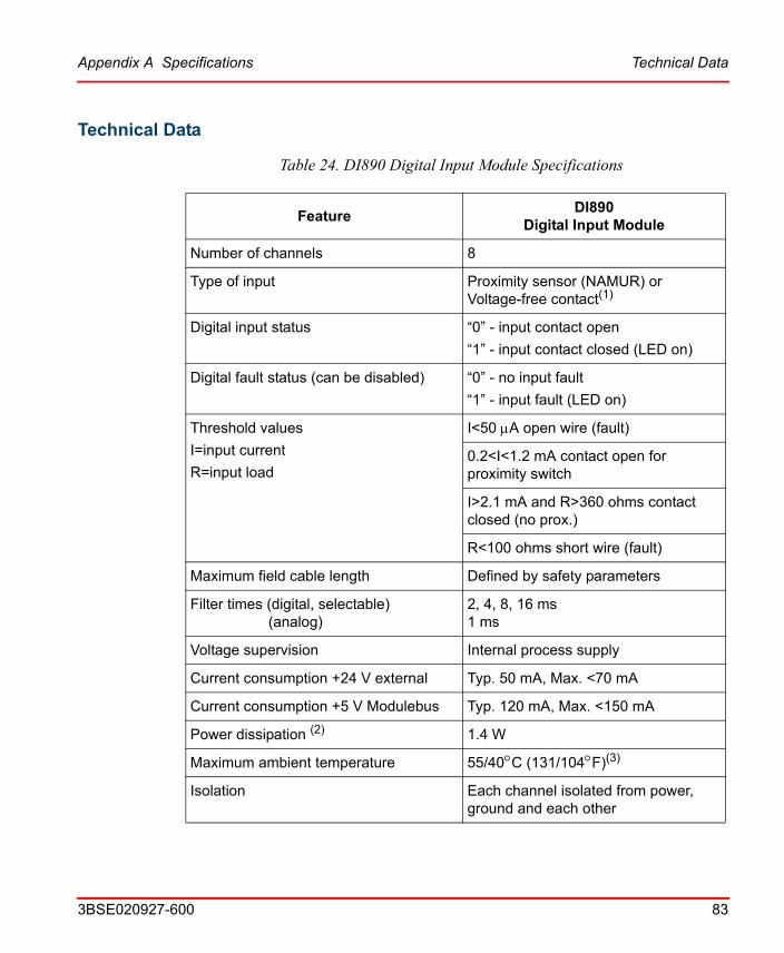
Appendix A Specifications Technical Data
3BSE020927-600 83
Technical Data
Table 24. DI890 Digital Input Module Specifications
FeatureDI890
Digital Input Module
Number of channels 8
Type of input Proximity sensor (NAMUR) or Voltage-free contact(1)
Digital input status “0” - input contact open
“1” - input contact closed (LED on)
Digital fault status (can be disabled) “0” - no input fault
“1” - input fault (LED on)
Threshold values
I=input current
R=input load
I<50 A open wire (fault)
0.2<I<1.2 mA contact open for proximity switch
I>2.1 mA and R>360 ohms contact closed (no prox.)
R<100 ohms short wire (fault)
Maximum field cable length Defined by safety parameters
Filter times (digital, selectable) (analog)
2, 4, 8, 16 ms1 ms
Voltage supervision Internal process supply
Current consumption +24 V external Typ. 50 mA, Max. <70 mA
Current consumption +5 V Modulebus Typ. 120 mA, Max. <150 mA
Power dissipation (2) 1.4 W
Maximum ambient temperature 55/40C (131/104F)(3)
Isolation Each channel isolated from power, ground and each other

Technical Data Appendix A Specifications
84 3BSE020927-600
Mounting termination units TU890, TU891
MTU keying code AA
Safety classification Class I according to IEC 536; (earth protected)
Protection rating IP20 according to IEC 529, (IEC 144)
Rated insulation voltage 50 V
Dielectric test voltage 500 V a.c.
Width 45 mm (1.77”)
Depth 97 mm (3.8”), 106 mm (4.2”) including connector
Height 119 mm (4.7”)
Weight 0.2 kg (0.44 lbs.)
(1) Fault detection with volt-free contacts requires 1 kohm series plus 10 kohm parallel external resistors
(2) Power dissipation is calculated with 70 percent of the channels activated at nominal voltage of 24 Volts.
(3) 40C104F) applies to Compact MTUs with I/O modules mounted on a vertical DIN rail.
Table 24. DI890 Digital Input Module Specifications (Continued)
FeatureDI890
Digital Input Module
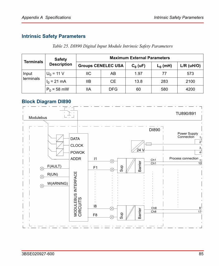
Appendix A Specifications Intrinsic Safety Parameters
3BSE020927-600 85
Intrinsic Safety Parameters
Table 25. DI890 Digital Input Module Intrinsic Safety Parameters
TerminalsSafety
Description
Maximum External Parameters
Groups CENELEC USA C0 (uF) L0 (mH) L/R (uH/O)
Input terminals
U0 = 11 V IIC AB 1.97 77 573
I0 = 21 mA IIB CE 13.8 283 2100
P0 = 58 mW IIA DFG 60 580 4200
Block Diagram DI890
24 V
DATA
Modulebus
CLOCK
POWOK
ADDR
MO
DU
LE
BU
S I
NT
ER
FAC
EC
IRC
UIT
S
DI890
TU890/891
W(ARNING)
R(UN)
F(AULT)Ch1Ch1
Ch8Ch8
Bar
rier
Sup
Bar
rier
Sup
I1
F1
I8
F8
Power SupplyConnection 1
8
4
3
2
17
101
Process connection
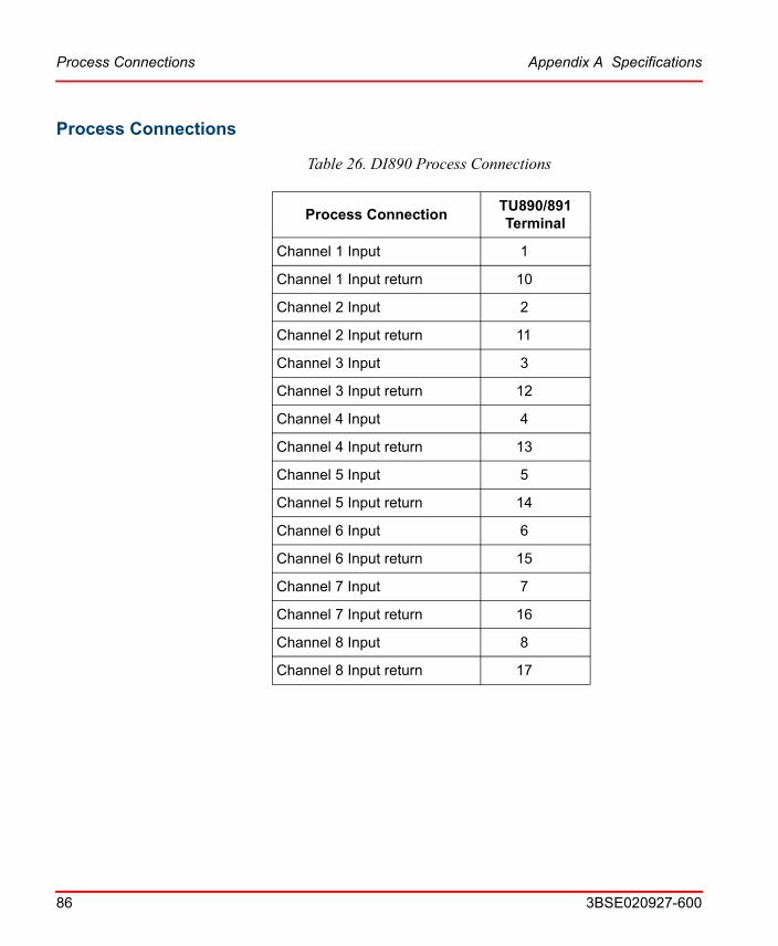
Process Connections Appendix A Specifications
86 3BSE020927-600
Process Connections
Table 26. DI890 Process Connections
Process ConnectionTU890/891Terminal
Channel 1 Input 1
Channel 1 Input return 10
Channel 2 Input 2
Channel 2 Input return 11
Channel 3 Input 3
Channel 3 Input return 12
Channel 4 Input 4
Channel 4 Input return 13
Channel 5 Input 5
Channel 5 Input return 14
Channel 6 Input 6
Channel 6 Input return 15
Channel 7 Input 7
Channel 7 Input return 16
Channel 8 Input 8
Channel 8 Input return 17
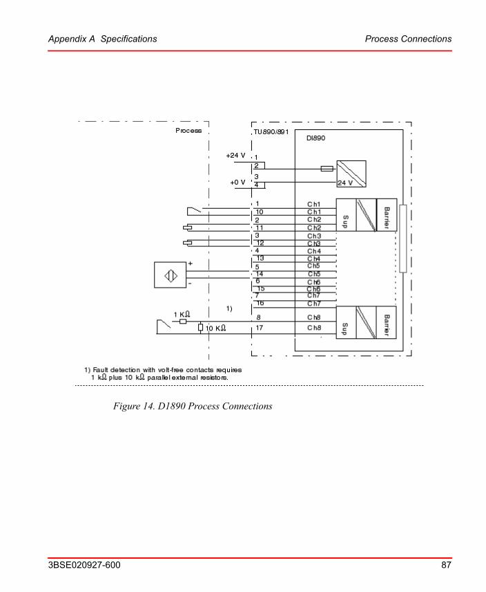
Figure 14. D1890 Process Connections
Appendix A Specifications Process Connections
3BSE020927-600 87
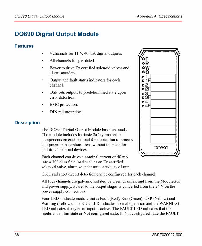
DO890 Digital Output Module Appendix A Specifications
88 3BSE020927-600
DO890 Digital Output Module
Features
• 4 channels for 11 V, 40 mA digital outputs.
• All channels fully isolated.
• Power to drive Ex certified solenoid valves and alarm sounders.
• Output and fault status indicators for each channel.
• OSP sets outputs to predetermined state upon error detection.
• EMC protection.
• DIN rail mounting.
Description
The DO890 Digital Output Module has 4 channels. The module includes Intrinsic Safety protection components on each channel for connection to process equipment in hazardous areas without the need for additional external devices.
Each channel can drive a nominal current of 40 mA into a 300 ohm field load such as an Ex certified solenoid valve, alarm sounder unit or indicator lamp.
Open and short circuit detection can be configured for each channel.
All four channels are galvanic isolated between channels and from the ModuleBus and power supply. Power to the output stages is converted from the 24 V on the power supply connections.
Four LEDs indicate module status Fault (Red), Run (Green), OSP (Yellow) and Warning (Yellow). The RUN LED indicates normal operation and the WARNING LED indicates if any error input is active. The FAULT LED indicates that the module is in Init state or Not configured state. In Not configured state the FAULT

Appendix A Specifications Description
3BSE020927-600 89
LED is turned off after the first valid access to the module. The OSP LED is turned on when the output is set to the predetermined OSP value.
In addition there are two LEDs for each channel to show CHANNEL STATE (Yellow) (On = 1 and Off = 0) and CHANNEL FAULT (Red). The channel fault indication can be disabled when not required.
The module performs self-diagnostic checks cyclically. Module diagnostics include: Process power supply supervision which is reported when supply voltage to the output circuitry is too low. This error is reported but the module will continue to function within the power supply limits because the output current is supervised. Channel diagnostics include: Fault detection of the channel (only reported on active channels). Fault detection of the field wiring is carried out in both the “energized” and “de-energized” state of the output channel.
The outputs of the module will be set to a predetermined value if the OSP-watchdog timer expires or ordered by the FCI. The watchdog timer which is in the range 256ms-1024ms is used for modulebus supervision. Three different values are possible, 256, 512 and 1024ms. The watchdog timer can also be disabled, which is the default after reset or power-up. The watchdog timer is re-triggered every time the correct node address has been decoded (or broadcast). If the watchdog timer expires or if the SetOSPState command is received, the module enters the OSP state and the active outputs (if any) are set to their OSP values which can be configured as a predefined value or to the last good value sent.
The output values will be kept as long as the module stays in the OSP state. To change the outputs the module first has to leave this state. This is done with an explicit command or if the BLOCK or POWOK signal is activated. When reentering Operational State, the outputs are still kept within their OSP value until new valid values are written.
The reset circuitry gives a reset signal when the module is inserted until the BLOCK signal is inactive and the POWOK signal is active. The BLOCK signal is deactivated when the module lock mechanism is in the locked position. The POWOK comes from the FCI after power is applied.
TU890 and TU891 Compact MTU can be used with this module and it enables two wire connection to the process devices without additional terminals. TU890 for Ex applications and TU891 for non Ex applications.

Technical Data Appendix A Specifications
90 3BSE020927-600
Technical Data
Table 27. DO890 Digital Output Module Specifications
FeatureDO890
Digital Output Module
Number of channels 4
Type of output Solenoid driver
Output range See characteristic see Figure 15
Output load 100<Load<5000 ohms
Short circuit fault detection limit <20 ohms
Open circuit fault detection limit >100 kohms
Fault sense current <4 mA
Digital output status “0” - output de-energized
“1” - output energized (LED on)
Digital fault status (can be disabled) “0” - no output fault
“1” - output fault (LED on)
Maximum Field Cable Length Defined by safety parameters
Output Set as Predetermined (OSP) timer 256, 512, 1024 ms
Output response time 1 ms turn on
2 ms turn off
Current consumption 24 V external Typ. 250 mA, Max. <360 mA
Current consumption 5 V Modulebus Typ. 80 mA, Max. <150 mA
Power dissipation 4.4 W
Maximum ambient temperature 55/40C (131/104F)(1)
Voltage supervision Internal process supply
Isolation Each channel isolated from power, ground and each other

Appendix A Specifications Intrinsic Safety Parameters
3BSE020927-600 91
Intrinsic Safety Parameters
Table 28. DO890 Digital Output Module Intrinsic Safety Parameters
TerminalsSafety
Description
Maximum External Parameters
Groups CENELEC USA C0 (uF) L0 (mH) L/R (uH/O)
Powered output terminals
U0 = 26 V IIC AB 0.099 4.1 58
I0 = 93 mA IIB CE 0.77 16.4 234
P0 = 605 mW IIA DFG 2.6 32.8 469
Mounting termination units TU890
MTU keying code AB
Safety classification Class I according to IEC 536; (earth protected)
Protection rating IP20 according to IEC 529, (IEC 144)
Rated insulation voltage 50 V
Dielectric test voltage 500 V a.c.
Width 45 mm (1.77”)
Depth 97 mm (3.8”), 106 mm (4.2”) including connector
Height 119 mm (4.7”)
Weight 0.2 kg (0.44 lbs.)
(1) 40C104F) applies to Compact MTUs with I/O modules mounted on a vertical DIN rail.
Table 27. DO890 Digital Output Module Specifications (Continued)
FeatureDO890
Digital Output Module
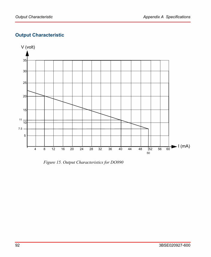
Output Characteristic Appendix A Specifications
92 3BSE020927-600
Output Characteristic
Figure 15. Output Characteristics for DO890
5
124 16 20 24 28 32 36 40 44 48 52 56 60
10
15
20
25
30
35
850
V (volt)
I (mA)
11
7.5

Appendix A Specifications Block Diagram DO890
3BSE020927-600 93
Block Diagram DO890
24 V
DATA
Modulebus
CLOCK
POWOK
ADDR
MO
DU
LEB
US
INT
ER
FAC
EC
IRC
UIT
S
DO890
TU890/891
W(ARNING)
R(UN)
F(AULT)Ch1Ch1
Ch4Ch4
Sup
Sup
O1
F1
O8
F8
O(SP)
Bar
rier
Bar
rier
Power SupplyConnection 1
4
4
3
2
13
101
Process connection
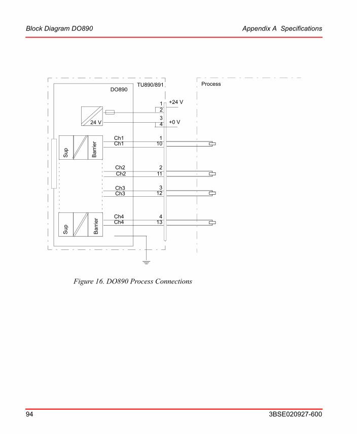
Figure 16. DO890 Process Connections
24 V
DO890
Ch4
Sup
Sup
Bar
rier
Bar
rier
Ch4
Ch1Ch1
Ch2Ch2
Ch3Ch3
110
211
312
413
12
34
ProcessTU890/891
+24 V
+0 V
Block Diagram DO890 Appendix A Specifications
94 3BSE020927-600
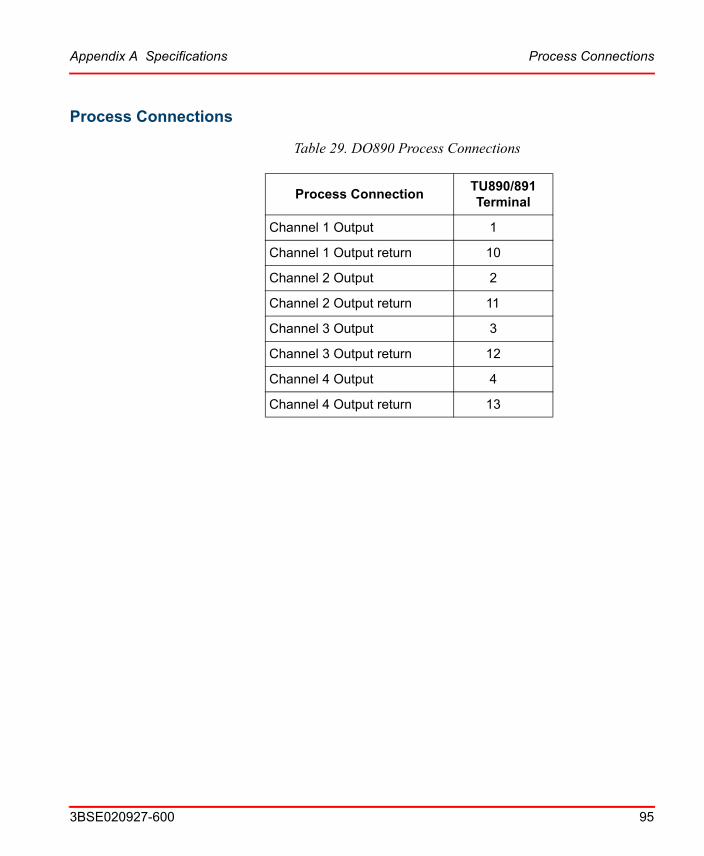
Appendix A Specifications Process Connections
3BSE020927-600 95
Process Connections
Table 29. DO890 Process Connections
Process ConnectionTU890/891Terminal
Channel 1 Output 1
Channel 1 Output return 10
Channel 2 Output 2
Channel 2 Output return 11
Channel 3 Output 3
Channel 3 Output return 12
Channel 4 Output 4
Channel 4 Output return 13
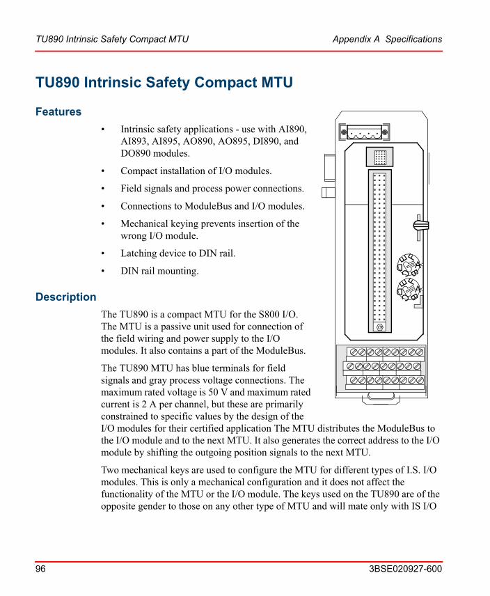
TU890 Intrinsic Safety Compact MTU Appendix A Specifications
96 3BSE020927-600
TU890 Intrinsic Safety Compact MTU
Features
ABCD
E F
ABCD
E F
• Intrinsic safety applications - use with AI890, AI893, AI895, AO890, AO895, DI890, and DO890 modules.
• Compact installation of I/O modules.
• Field signals and process power connections.
• Connections to ModuleBus and I/O modules.
• Mechanical keying prevents insertion of the wrong I/O module.
• Latching device to DIN rail.
• DIN rail mounting.
Description
The TU890 is a compact MTU for the S800 I/O. The MTU is a passive unit used for connection of the field wiring and power supply to the I/O modules. It also contains a part of the ModuleBus.
The TU890 MTU has blue terminals for field signals and gray process voltage connections. The maximum rated voltage is 50 V and maximum rated current is 2 A per channel, but these are primarily constrained to specific values by the design of the I/O modules for their certified application The MTU distributes the ModuleBus to the I/O module and to the next MTU. It also generates the correct address to the I/O module by shifting the outgoing position signals to the next MTU.
Two mechanical keys are used to configure the MTU for different types of I.S. I/O modules. This is only a mechanical configuration and it does not affect the functionality of the MTU or the I/O module. The keys used on the TU890 are of the opposite gender to those on any other type of MTU and will mate only with IS I/O

Appendix A Specifications Technical Data
3BSE020927-600 97
modules. Each key has six positions, which gives a total number of 36 different configurations. The configuration can be changed with a screwdriver.
The MTU can be mounted on a standard DIN rail. It has a mechanical latch that locks the MTU to the DIN rail. The latch can be released with a screwdriver.
The MTU has a mechanical locking mechanism that locks the module in its position. This mechanism also gives the signal BLOCK to the I/O module that keeps the module in its init state until it is locked in its position.
The top part of the MTU can be removed to replace the termination board even with an operational system. Such a need can be caused by a damaged terminal screw.
Technical Data
Table 30. TU890 Compact MTU Specifications
Item Value
Process Connections 27 blue terminals
Rated maximum continuous current per I/O channel
2 A
PowerBus 24 V current 1.5 A
ModuleBus:Maximum 5 V current distributionMaximum 24 V current distribution
1.5 A1.5 A
Acceptable Wire Sizes
Process connecter
Solid: 0.2 - 4 mm2
Stranded: 0.2 - 2.5 mm2, 24 - 12 AWG
Recommended torque 0.5 - 0.6 Nm
Acceptable Wire Sizes
Power supply connector
0.25 - 2.5 mm2, 24 - 14 AWG
Recommended torque
0.5 - 0.6 Nm
Mechanical Keys (2) 36 different combinations
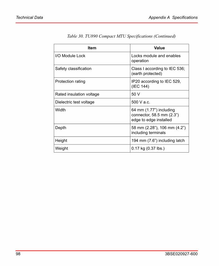
Technical Data Appendix A Specifications
98 3BSE020927-600
I/O Module Lock Locks module and enables operation
Safety classification Class I according to IEC 536; (earth protected)
Protection rating IP20 according to IEC 529, (IEC 144)
Rated insulation voltage 50 V
Dielectric test voltage 500 V a.c.
Width 64 mm (1.77”) including connector, 58.5 mm (2.3”) edge to edge installed
Depth 58 mm (2.28”), 106 mm (4.2”) including terminals
Height 194 mm (7.6”) including latch
Weight 0.17 kg (0.37 lbs.)
Table 30. TU890 Compact MTU Specifications (Continued)
Item Value
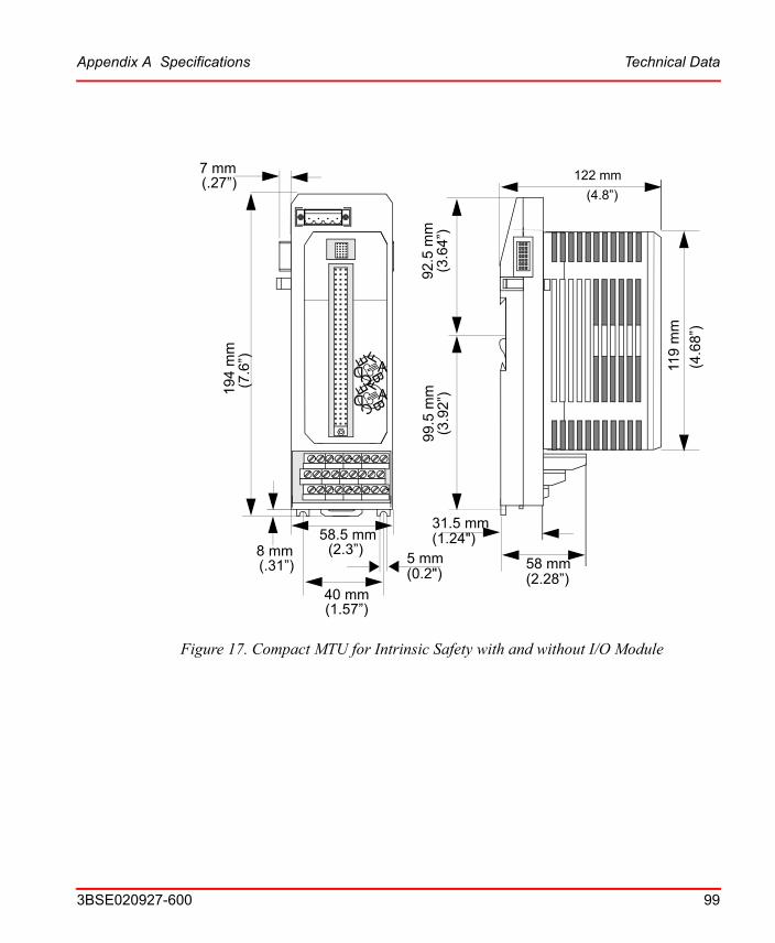
Figure 17. Compact MTU for Intrinsic Safety with and without I/O Module
194
mm
58.5 mm8 mm
7 mm
5 mm
(.27”)
(7.6
”)
(2.3”) (.31”) (0.2")
58 mm(2.28”)
122 mm
(4.8”)
(4.6
8”)
119
mm
40 mm(1.57”)
92.5
mm
(3.6
4”)
99
.5 m
m(3
.92
”)
31.5 mm (1.24")
ABCD
EFABCD
EF
Appendix A Specifications Technical Data
3BSE020927-600 99

Connections Appendix A Specifications
100 3BSE020927-600
Connections
Figure 18. TU890 Process Connections
ABCD
E F
ABCD
E F Process connection
Power Supply connection
Blue Terminal Block321
10
87654 9
11 12 13 14 15 16 17 18
19 20 21 22 23 24 25 26 27

Appendix A Specifications Block Diagram TU890
3BSE020927-600 101
Block Diagram TU890
ModulebusTU890
Ch 1
Ch 2
Ch 3
Ch 4
Ch 5
Ch 6
Ch 7
Ch 8
Power supply+_
Mod
ule
Bus
con
nect
or
I/O m
odul
e p
roce
ss c
onne
ctor
CJ
20
13
12
11
1910
21
22
23
24
2
14
15
16
17
3
4
1
5
6
7
8
9
25
26
18
++27
__

TU891 Compact MTU Appendix A Specifications
102 3BSE020927-600
TU891 Compact MTU
Features
ABCD
E F
ABCD
E F
• Used with AI890, AI893, AI895, AO890, AO895, DI890, and DO890.
• Compact installation of I/O modules.
• Shall only be used when mounting in the safe area and when interfacing to field devices in the safe area.
• Field signals and process power connections.
• Connections to ModuleBus and I/O modules.
• Mechanical keying prevents insertion of the wrong I/O module.
• Latching device to DIN rail.
• DIN rail mounting.
• Also in G3 compliant version.
Description
The TU891 is a compact MTU for the S800 I/O. The MTU is a passive unit used for connection of the field wiring and power supply to the I/O modules. It also contains a part of the ModuleBus.
The TU891 MTU has gray terminals for field signals and process voltage connections. The maximum rated voltage is 50 V and maximum rated current is 2 A per channel, but these are primarily constrained to specific values by the design of the I/O modules for their certified application. The MTU distributes the ModuleBus to the I/O module and to the next MTU. It also generates the correct address to the I/O module by shifting the outgoing position signals to the next MTU.
Two mechanical keys are used to configure the MTU for different types of I.S. I/O modules. This is only a mechanical configuration and it does not affect the
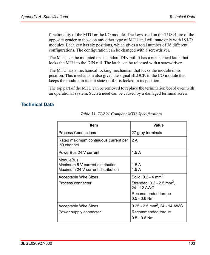
Appendix A Specifications Technical Data
3BSE020927-600 103
functionality of the MTU or the I/O module. The keys used on the TU891 are of the opposite gender to those on any other type of MTU and will mate only with IS I/O modules. Each key has six positions, which gives a total number of 36 different configurations. The configuration can be changed with a screwdriver.
The MTU can be mounted on a standard DIN rail. It has a mechanical latch that locks the MTU to the DIN rail. The latch can be released with a screwdriver.
The MTU has a mechanical locking mechanism that locks the module in its position. This mechanism also gives the signal BLOCK to the I/O module that keeps the module in its init state until it is locked in its position.
The top part of the MTU can be removed to replace the termination board even with an operational system. Such a need can be caused by a damaged terminal screw.
Technical Data
Table 31. TU891 Compact MTU Specifications
Item Value
Process Connections 27 gray terminals
Rated maximum continuous current per I/O channel
2 A
PowerBus 24 V current 1.5 A
ModuleBus:Maximum 5 V current distributionMaximum 24 V current distribution
1.5 A1.5 A
Acceptable Wire Sizes
Process connecter
Solid: 0.2 - 4 mm2
Stranded: 0.2 - 2.5 mm2, 24 - 12 AWG
Recommended torque 0.5 - 0.6 Nm
Acceptable Wire Sizes
Power supply connector
0.25 - 2.5 mm2, 24 - 14 AWG
Recommended torque
0.5 - 0.6 Nm
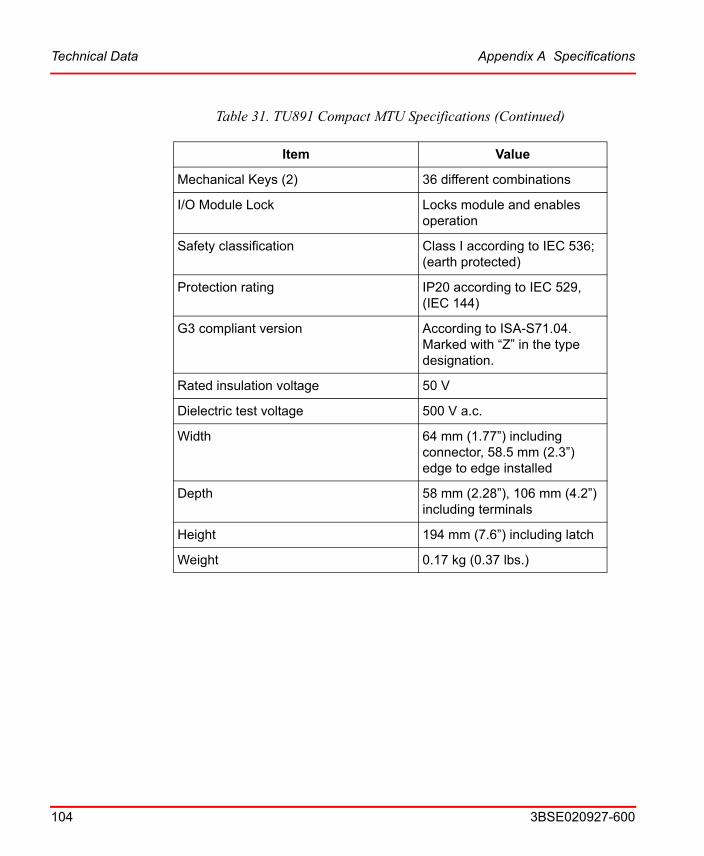
Technical Data Appendix A Specifications
104 3BSE020927-600
Mechanical Keys (2) 36 different combinations
I/O Module Lock Locks module and enables operation
Safety classification Class I according to IEC 536; (earth protected)
Protection rating IP20 according to IEC 529, (IEC 144)
G3 compliant version According to ISA-S71.04. Marked with “Z” in the type designation.
Rated insulation voltage 50 V
Dielectric test voltage 500 V a.c.
Width 64 mm (1.77”) including connector, 58.5 mm (2.3”) edge to edge installed
Depth 58 mm (2.28”), 106 mm (4.2”) including terminals
Height 194 mm (7.6”) including latch
Weight 0.17 kg (0.37 lbs.)
Table 31. TU891 Compact MTU Specifications (Continued)
Item Value

Figure 19. Compact MTU for non Intrinsic Safety applications with and without I/O Module
ABCD
E FABC
DE F
194
mm
58.5 mm8 mm
7 mm
5 mm
(.27”)
(7.6
”)
(2.3”) (.31”) (0.2")
58 mm(2.28”)
122 mm
(4.8”)
(4.6
8”)
119
mm
40 mm(1.57”)
92.5
mm
(3.6
4”)
99
.5 m
m(3
.92
”)
31.5 mm (1.24")
Appendix A Specifications Technical Data
3BSE020927-600 105
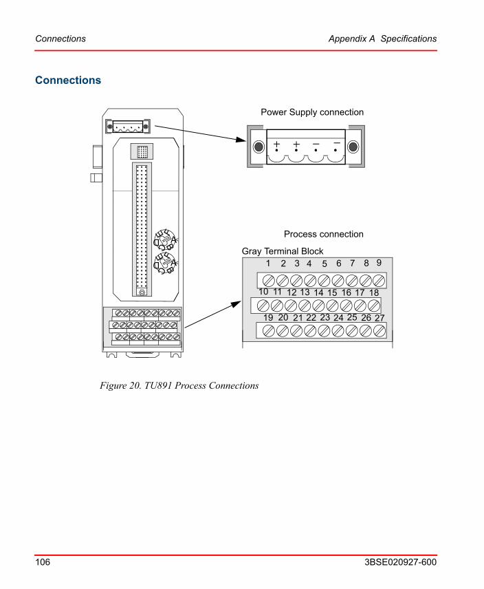
Connections Appendix A Specifications
106 3BSE020927-600
Connections
Figure 20. TU891 Process Connections
ABCD
E F
ABCD
E F Process connection
Power Supply connection
Gray Terminal Block321
10
87654 9
11 12 13 14 15 16 17 18
19 20 21 22 23 24 25 26 27
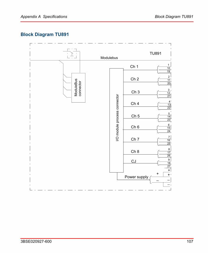
Appendix A Specifications Block Diagram TU891
3BSE020927-600 107
Block Diagram TU891
ModulebusTU891
Ch 1
Ch 2
Ch 3
Ch 4
Ch 5
Ch 6
Ch 7
Ch 8
Power supply+_
Mod
ule
Bus
con
nect
or
I/O m
odul
e p
roce
ss c
onne
ctor
CJ
20
13
12
11
1910
21
22
23
24
2
14
15
16
17
3
4
1
5
6
7
8
9
25
26
18
++27
__

Block Diagram TU891 Appendix A Specifications
108 3BSE020927-600

3BSE020927-600 109
Appendix B Introduction to ATEX Directives
ScopeThis introduction is intended to give information regarding the use of equipment in a specific category in order to be used safely in the intended potentially explosive atmosphere under the expected operating conditions.
The S890 equipment has been designed to interface intrinsically safe signals but also for use in Zone 2 as Category 3 (1) G apparatus under the ATEX100A directive. In the ATEX 100A Marking section, an explanation of the marking is available.
GeneralThis section gives an introduction to the global approach EU Directives relevant to design, manufacture and use of apparatus and protective system for use in potentially explosive atmosphere (also known as hazardous area).
The ATEX 100A Directive 94/9/EC of the European Parliament and the Council, dated 23 March 1994, directive was created to cover the design of all apparatus and system that will be used in explosive atmospheres. It specifies essential safety requirements with which apparatus must comply and was introduced as an optional directive from 1 March 1996 with the ruling that it becomes mandatory after 30 June 2003.
The ATEX 137 Directive 99/92/EC of the European Parliament (formerly known as 118A, due to a revision on the European Union Treaty) covers the classification and the installation of apparatus to improve the health and safety protection of all workers potentially at risk from explosive atmospheres. This Directive is so intended to complement the previously published ATEX 100A Directive, and it becomes mandatory after 30 June 2003. All existing hazardous area work places in
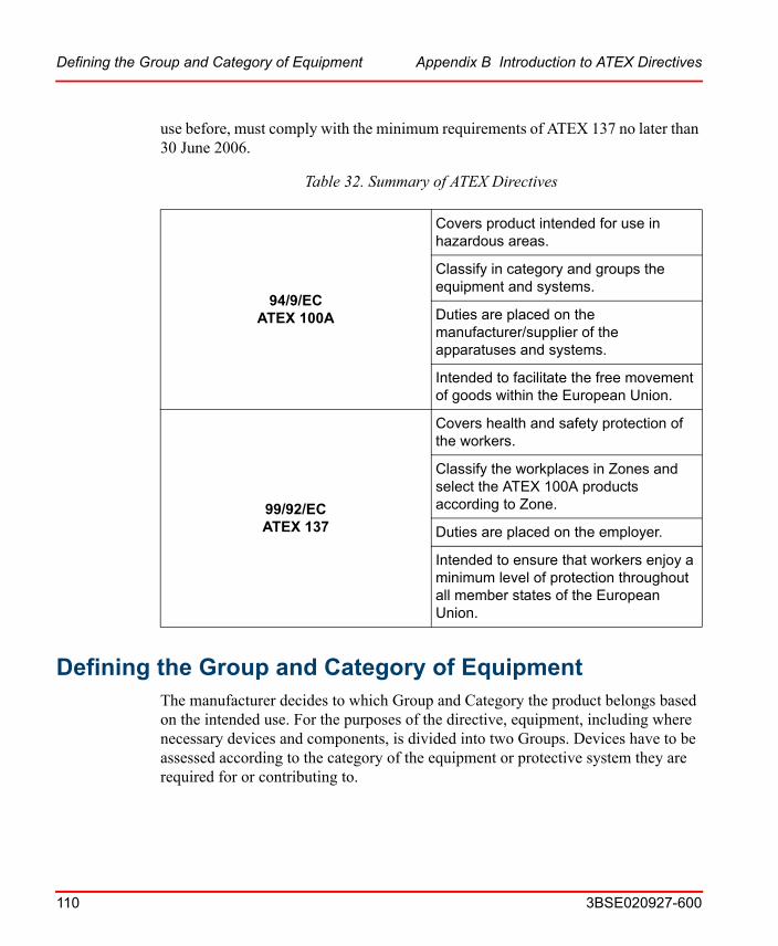
Defining the Group and Category of Equipment Appendix B Introduction to ATEX Directives
110 3BSE020927-600
use before, must comply with the minimum requirements of ATEX 137 no later than 30 June 2006.
Defining the Group and Category of EquipmentThe manufacturer decides to which Group and Category the product belongs based on the intended use. For the purposes of the directive, equipment, including where necessary devices and components, is divided into two Groups. Devices have to be assessed according to the category of the equipment or protective system they are required for or contributing to.
Table 32. Summary of ATEX Directives
94/9/ECATEX 100A
Covers product intended for use in hazardous areas.
Classify in category and groups the equipment and systems.
Duties are placed on the manufacturer/supplier of the apparatuses and systems.
Intended to facilitate the free movement of goods within the European Union.
99/92/ECATEX 137
Covers health and safety protection of the workers.
Classify the workplaces in Zones and select the ATEX 100A products according to Zone.
Duties are placed on the employer.
Intended to ensure that workers enjoy a minimum level of protection throughout all member states of the European Union.
Appendix B Introduction to ATEX Directives Group I
3BSE020927-600 111
Group I
Group I comprises equipment intended for use in the underground parts of mines, and to those parts of surface installations of such mines, likely to become endangered by firedamp and/or combustible dust.
Group II
Group II comprises equipment intended for use in other places likely to become endangered by explosive atmospheres.
These Groups are sub-divided into Categories. For Group I, the categorization depends on (amongst other factors) whether the product is to be de-energized in the event of an explosive atmosphere occurring. For Group II, it depends where the product is intended to be used and whether a potentially explosive atmosphere is always present, or is likely to occur for a long or a short period of time.
Devices have been assessed according to the category of the equipment or protective system they are required for or contributing to.
Group I, Category
Category M1
Products of this Category are required to remain functional for safety reasons when an explosive atmosphere is present and is characterized by integrated explosion protection measures functioning in such a way that:
• in the event of failure of one integrated measure, at least a second means of protection provides for a sufficient level of safety; or,
• in the event of two faults occurring independently of each other, a sufficient level of safety is ensured.
Category M2
These products are intended to be de-energized in the event of an explosive atmosphere.
It is nonetheless foreseeable that explosive atmospheres could occur during the operation of Category M2 equipment, as the equipment might not be de-energized
Group II, Category Appendix B Introduction to ATEX Directives
112 3BSE020927-600
immediately. It is therefore necessary to incorporate protection measures, which provide a high level of safety. The protection measures relating to products of this Category provide a sufficient level of safety during normal operation even in the event of more severe operating conditions arising, from rough handling and changing environmental conditions.
Group II, Category
Category 1
Comprises products designed to be capable of remaining within its operational parameters, stated by the manufacturer, and ensuring a very high level of protection for its intended use in areas in which explosive atmospheres caused by mixtures of air and gases, vapors, mists or air/dusts mixtures are highly likely to occur and are present continuously, for long periods of time or frequently.
Equipment of this Category is characterized by integrated explosion protection measures functioning in such a way that:
• in the event of a failure of one integrated measure, at least a second independent means of protection provides for a sufficient level of safety; or,
• in the event of two faults occurring independently of each other a sufficient level of safety is ensured.
Category 2
Comprises products designed to be capable of remaining within their operational parameters, stated by the manufacturer, and based on a high level of protection for their intended use, in areas in which explosive atmospheres caused by mixtures of air and gases, vapors, mists or air/dust mixtures are likely to occur.
The explosion protection relating to this Category must function in such a way as to provide a sufficient level of safety even in the event of equipment with operating faults or in dangerous operating conditions which normally have to be taken into account.
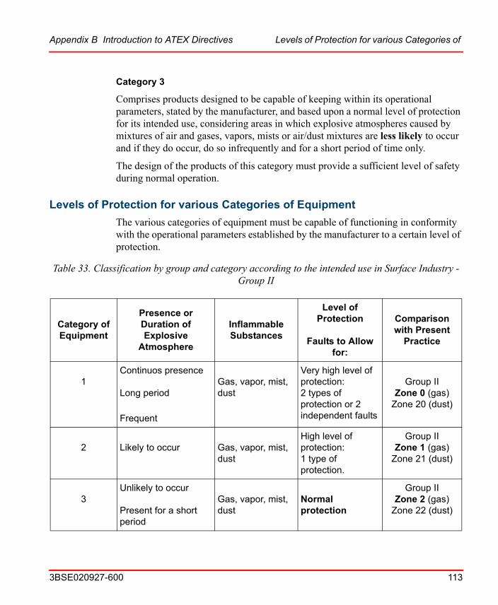
Appendix B Introduction to ATEX Directives Levels of Protection for various Categories of
3BSE020927-600 113
Category 3
Comprises products designed to be capable of keeping within its operational parameters, stated by the manufacturer, and based upon a normal level of protection for its intended use, considering areas in which explosive atmospheres caused by mixtures of air and gases, vapors, mists or air/dust mixtures are less likely to occur and if they do occur, do so infrequently and for a short period of time only.
The design of the products of this category must provide a sufficient level of safety during normal operation.
Levels of Protection for various Categories of Equipment
The various categories of equipment must be capable of functioning in conformity with the operational parameters established by the manufacturer to a certain level of protection.
Table 33. Classification by group and category according to the intended use in Surface Industry - Group II
Category of Equipment
Presence or Duration of Explosive
Atmosphere
Inflammable Substances
Level of Protection
Faults to Allow for:
Comparison with Present
Practice
1Continuos presenceLong period
Frequent
Gas, vapor, mist, dust
Very high level of protection:2 types of protection or 2 independent faults
Group IIZone 0 (gas)
Zone 20 (dust)
2Likely to occur
Gas, vapor, mist, dust
High level of protection:1 type of protection.
Group IIZone 1 (gas)
Zone 21 (dust)
3Unlikely to occurPresent for a short period
Gas, vapor, mist, dust
Normal protection
Group IIZone 2 (gas)
Zone 22 (dust)
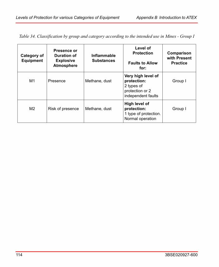
Levels of Protection for various Categories of Equipment Appendix B Introduction to ATEX
114 3BSE020927-600
Table 34. Classification by group and category according to the intended use in Mines - Group I
Category of Equipment
Presence or Duration of Explosive
Atmosphere
Inflammable Substances
Level of Protection
Faults to Allow for:
Comparison with Present
Practice
M1Presence
Methane, dust
Very high level of protection:2 types of protection or 2 independent faults
Group I
M2Risk of presence
Methane, dust
High level of protection:1 type of protection.Normal operation
Group I

3BSE020927-600 115
AAI890 17, 33, 35AI893 17, 33, 43AI895 17, 33, 55Analog input module
AI890 17, 35AI893 17, 43AI895 17, 55
Analog output moduleAO890 18, 65AO895 18, 73
AO890 18, 33, 65AO895 18, 33, 73
CCompact MTU 16, 96, 102
DDI890 18, 33, 81Digital input module
DI890 18, 81Digital output module
DO890 18, 88DO890 18, 34, 88
FFCI and I/O module replacement 31
GG3 compliant 11
II/O modules 16
LLEDs
I/O module 29
MModule termination units 14MTU key settings 27MTU usage 27MTUs 34
PProcess connections
AI890 40, 50AI895 61AO890 71AO895 79DI890 86DO890 95
TTU890 16, 34, 96TU891 16, 34, 102
INDEX

Index
116 3BSE020927-600
Index
116 3BSE020927-600

Power and productivity for a better worldTM
Contact us
Copyright© 2003-2014 ABB.All rights reserved.
3BS
E02
0927
-600www.abb.com/800xA
www.abb.com/controlsystems