s-tronic plus / lambda - hout-cv.eu · s-tronic plus / lambda ... port can be used as a modbus...
TRANSCRIPT

Service Manual
S-Tronic Plus / LambdaVersion 50.04 - Build 05.11
Translation of the original German operating instructions for techniciansRead and follow the instructions and safety information!
Technical changes, typographical errors and omissions reserved!B1010315_en | Edition 29/09/2015
Froling GesmbH | A-4710 Grieskirchen, Industriestraße 12 | www.froeling.com
Table of Contents
1 General 51.1 About these instructions 51.2 Safety information 5
2 Electrical connection and wiring 62.1 Core modules and connection options 62.1.1 Board view 6 Connection instructions 72.1.2 Board view for S-Tronic Plus 9 Connection instructions 102.1.3 Mains connection 112.1.4 Connecting the flue gas sensor 112.1.5 Heating circuit pump 0 / burner relay 112.1.6 Connecting the remote control 122.1.7 Connecting a high efficiency pump to the core module 132.2 Expansion modules 142.2.1 Heating circuit module 142.2.2 Hydraulic module 15 Connecting an isolating valve 16 Connecting a high efficiency pump to the hydraulic module 172.2.3 Return mixer module 182.2.4 Connecting the bus cable 202.2.5 Connect the patch cable to the bus plug 202.2.6 Setting end jumpers 202.2.7 Setting the module address 212.3 Connection diagrams according to pump types 22
3 Operation 233.1 Before switching on for the first time 233.1.1 Controller check 233.1.2 Check on the connected units 233.1.3 System Check 233.2 Initial startup 243.2.1 Changing the operating level 243.2.2 Setting the system type 253.2.3 Before heating up for the first time 27 Drives 27
3.3 Heating up the boiler 273.3.1 Heating up 273.4 Operating statuses 28
4 Menu overview and parameters 294.1 Heating 294.1.1 Heating - Status 294.1.2 Heating - Temperatures 304.1.3 Heating - Service 324.1.4 Heating - Heating up program 34 Heating up programs 35 Configure program 8 36
Table of Contents
2 Froling GesmbH | A-4710 Grieskirchen, Industriestraße 12 | www.froeling.com

Heating circuits used 364.1.5 Heating - General settings 374.2 Water 384.2.1 Water - Status 384.2.2 Water - Temperatures 394.2.3 Water - Service 404.3 Solar 424.3.1 Solar - Status 424.3.2 Solar - Temperatures 444.3.3 Solar - Service 464.3.4 Solar - Heat meter 504.4 Buffer tank 524.4.1 Buffer tank - Status 524.4.2 Buffer tank - Temperatures 534.4.3 Buffer tank - Service 544.5 Boiler 564.5.1 Boiler - Status 564.5.2 Boiler - Temperatures 584.5.3 Boiler - Service 594.5.4 Boiler - General settings 60 General settings - MODBUS settings 62
4.6 Boiler 2 634.6.1 Boiler 2 - Status 634.6.2 Boiler 2 - Temperatures 644.6.3 Boiler 2 - Service 654.7 Network pump 664.7.1 Network pump - Status 664.7.2 Network pump - Temperatures 684.7.3 Network pump - Service 694.8 Difference regulator 724.8.1 Difference regulator - Status 724.8.2 Difference regulator - Temperatures 734.8.3 Difference regulator - Service 744.9 Circulation pump 754.9.1 Circulation pump - Status 754.9.2 Circulation pump - Temperatures 764.9.3 Circulation pump - Service 774.10 Manual 784.10.1 Manual - Digital outputs 784.10.2 Manual - Analogue outputs 794.10.3 Manual - Digital inputs 814.11 System 824.11.1 System - Settings 82 Setting - Boiler temperature 82 Setting - Flue gas 83 Setting - Air settings 84 Setting - Lambda values 86 Setting - Lambda values - LSM11 Lambda probe 86 Setting - Lambda values - Broadband probe 87 Setting - General settings 894.11.2 System - Current values 914.11.3 System - Error 93 Error - Error display 93 Error - Clear pending error 93
Table of Contents
Service Manual S-Tronic Plus / Lambda | B1010315_en 3

Error - Error history 93 Error - Clear error history 934.11.4 System - Sensors and pumps 944.11.5 System - Display operating rights 954.11.6 System - Display allocations 974.11.7 System - Basic display parameters 994.11.8 System - Language 1004.11.9 System - Current Date 1004.11.10 System - Current Time 1004.11.11 System - Current User Level 1014.11.12 System - System selection 101
5 FAQ 1025.1 PWM / 0 - 10V settings 102
6 Menu structure - S-Tronic Plus / Lambda 103
Table of Contents
4 Froling GesmbH | A-4710 Grieskirchen, Industriestraße 12 | www.froeling.com

1 General
1.1 About these instructionsPlease read and follow the operating instructions, in particular the safety informationcontained therein. Keep them available next to the boiler.These operating instructions contain important information about operation, electricalconnection and troubleshooting for the S-Tronic Lambda control.
NOTICE
The values given in the parameter lists are examples, and should not be used as standard values!
The constant further development of our products means that there may be minordifferences from the pictures and content. If you discover any errors, please let usknow.
1.2 Safety information
DANGER
When working on electrical components:
Risk of electrocution!
When work is carried out on electrical components:❒ Only have work carried out by a qualified electrician❒ Observe the applicable standards and regulations
➥ Work must not be carried out on electrical components by unauthorisedpeople
WARNING
When touching hot surfaces:
Severe burns are possible on hot surfaces and the flue gas pipe!
When work is carried out on the boiler:❒ Shut down the boiler in a controlled way (operating status "Off") and allow it to
cool down❒ Protective gloves must generally be worn for work on the boiler, and it should
only be operated using the handles provided❒ Insulate the flue pipes or simply avoid touching them during operation.
The information on safety, standards and guidelines in assembly and operatinginstructions for the boiler should also be observed.
General 1About these instructions
Service Manual S-Tronic Plus / Lambda | B1010315_en 5

2 Electrical connection and wiring
2.1 Core modules and connection options
2.1.1 Board view
2 Electrical connection and wiringCore modules and connection options
6 Froling GesmbH | A-4710 Grieskirchen, Industriestraße 12 | www.froeling.com

Connection instructions
Port Cable dimensions / Specifications / Information
Bus (1) Port with cable – LIYCY paired 2x2x0.5;⇨ See "Connecting the bus cable" [page 20]❒ Warning! CAN L and CAN H must not be connected to +UBUS!
Bus (2) Patch cable CAT 5 RJ45 SFTP 1:1 configuration
Bus (3) Patch cable CAT 5 RJ45 SFTP 1:1 configuration, boiler display port
COM 2 (4) Null modem cable 9-pin SUB-D;❒ Port can be used as a MODBUS interfaceGeneral Settings
COM 1 (5) Null modem cable 9-pin SUB-D;❒ Service interface for installing new boiler software or port for the visualisation
software
Broadband probe (6) Connection cable1) 5 x 0.75 mm2
❒ Connection of a BOSCH or NTK broadband Lambda probe
Secondary air (7) Connection cable1) 5 x 0.75 mm²❒ When using the S1 Turbo firewood boiler, the air flap must be connected a the
“Secondary air” connection port
Primary air (8) Connection cable1) 5 x 0.75 mm²
Latch (9) Connection cable1) 2 x 0.75 mm2
High-limit thermostat - STL (10)
EMERGENCY STOP (11) Connection cable1) 2 x 0.75 mm2
❒ Warning! Do not connect the emergency off/emergency stop switch to the powersupply cable of the boiler. The switch must be a N/C switch and it must be linkedto the 24V safety chain of the STL at this terminal.
Flowmeter FLM (12) Connection cable1) 2 x 0.75 mm2
Lambda probe (13) Connection cable1) 4 x 0.75 mm²❒ LSM11 Lambda probe connection
Boiler release (14) Connection cable1) 2 x 0.75 mm2
❒ Warning! The connection must be a floating connection.
Flue gas temperature sensor(15)
Connection cable1) 3 x 0.75 mm2
Door switch DCS (16) Connection cable1) 2 x 0.75 mm2
Sensor 2/1 (17/18) Connection cable1) 2 x 0.75 mm2
Outside temperature sensor(19)
Connection cable1) 2 x 0.75 mm2,shielded from 25m cable length
Room temperature sensor 2/1(20/21)
Flow temperature sensor 2/1(22/23)
Return sensor RTS (24) Connection cable1) 2 x 0.75 mm2
Boiler sensor BS (25)
Electrical connection and wiring 2Core modules and connection options
Service Manual S-Tronic Plus / Lambda | B1010315_en 7

Port Cable dimensions / Specifications / Information
PDM / 0-10V Pump 1 (26)
Induced draught (27) Connection cable1) 3 x 1.5 mm2, power supplyConnection cable1) 3 x 0.75 mm2, analysis of current speed
Pump 1 on core module (28) Connection cable1) 3 x 1.5 mm2, max. 1.5A / 280W / 230V
Mains (29) Connection cable 1) 3 x 1.5 mm2; fused with 16A (provided by the customer)
Mixing valve 2/1 (30/31) Connection cable1) 4 x 0.75 mm2, max. 0.15A / 230V
Heating circuit pump 2/1(32/33)
Connection cable1) 3 x 1.5 mm2, max. 2.5A / 500W
Heating circuit pump HCP 0 /burner relay (34)
Connection cable1) 3 x 1.5 mm2, max. 3A / 600VA
(35) Connection cable1) 2 x 0.75mm2
1.YMM as per ÖVE-K41-5 or H05VV-F as per DIN VDE 0881-5
2 Electrical connection and wiringCore modules and connection options
8 Froling GesmbH | A-4710 Grieskirchen, Industriestraße 12 | www.froeling.com

2.1.2 Board view for S-Tronic Plus
Electrical connection and wiring 2Core modules and connection options
Service Manual S-Tronic Plus / Lambda | B1010315_en 9

Connection instructions
Port Cable dimensions / Specifications / Information
Bus (1) Port with cable – LIYCY paired 2x2x0.5;⇨ See "Connecting the bus cable" [page 20]❒ Warning! CAN L and CAN H must not be connected to +UBUS!
Bus (2) Patch cable CAT 5 RJ45 SFTP 1:1 configuration
Bus (3) Patch cable CAT 5 RJ45 SFTP 1:1 configuration, boiler display port
COM 2 (4) Null modem cable 9-pin SUB-D
COM 1 (5) Null modem cable 9-pin SUB-D;❒ Service interface for installing new boiler software or port for the visualisation
software
High-limit thermostat (STL) (6) Connection cable1) 2 x 0.75 mm2
EMERGENCY STOP (7) Connection cable1) 2 x 0.75 mm2
❒ Warning! Do not connect the emergency off/emergency stop switch to the powersupply cable of the boiler. The switch must be a N/C switch and it must be linkedto the 24V safety chain of the STL at this terminal.
Flue gas temperature sensor(8)
Connection cable1) 3 x 0.75 mm2
Door switch (9) Connection cable1) 2 x 0.75 mm2
Sensor 2/1 (10/11) Connection cable1) 2 x 0.75 mm2, shielded from 25 m cable length Outside temperature sensor
(12)
Room temperature sensor 2/1(13/14)
Flow temperature sensor 2/1(15/16)
Return sensor RTS (17) Connection cable1) 2 x 0.75 mm2
Boiler sensor BS (18)
PDM / 0-10V Pump 1 (19)
Induced draught (20) Connection cable1) 5 x 0.75 mm2
Pump 1 on core module (21) Connection cable1) 3 x 0.75 mm2; max. 1.5A / 280W / 230V
Mains (22) Connection cable 1) 3 x 1.5 mm2; fused with 16A (provided by the customer)
Mixing valve 2/1 (23/24) Connection cable1) 4 x0.75 mm2, max. 0.15A / 230V
Heating circuit pump HKP 2/1(25/26)
Connection cable1) 3 x 1.5 mm2, max. 2.5A / 500W
Heating circuit pump 0 / burnerrelay (27)
Connection cable1) 3 x 1.5 mm2, max. 3A / 600VA
1.YMM as per ÖVE-K41-5 or H05VV-F as per DIN VDE 0881-5
2 Electrical connection and wiringCore modules and connection options
10 Froling GesmbH | A-4710 Grieskirchen, Industriestraße 12 | www.froeling.com

2.1.3 Mains connectionConnect the power supply at the "Mains connection" plug❒ Flexible sheathed cable must be used for the wiring; this must be of the correct
size to comply with applicable regional standards and regulations.❒ The power supply line (mains connection) must be fitted with a 16A fuse by the
customer. If a safety overload switch is used it should be a type with 16A.
2.1.4 Connecting the flue gas sensor
green-yellow
red +
blue -
Core module
2.1.5 Heating circuit pump 0 / burner relayThe connection "Heating circuit pump 0" can be used for heating circuit pump 0 or asburner relays depending on the system setting. Connecting a HCP 0 up to max. 2 Ampere:
Core module
L1
N
HCP0
Connecting a HCP 0 up to max. 5 Ampere:
Connection as burner relays:
Core module
L1
N
To oil boiler control:
floating contact for burner
release
1
Electrical connection and wiring 2Core modules and connection options
Service Manual S-Tronic Plus / Lambda | B1010315_en 11

2.1.6 Connecting the remote controlA room temperature sensor is included in the remote control, which sends the currentroom temperature to the control.
affecting room:
���
���
�����
���
��
����
���
������ �����
�����
�����������������
not affecting room:
���
���
�����
���
��
����
���
������ �����
�����
�����������������
Switch settings:
Switched-off Heating circuit deactivated, only frostprotection!
Automatic mode Heating phases according to setback program
Setback mode Ignores the heating phases
Override circuit Ignores the setback
Handwheel… Allows you to adjust the temperature by +/- 3°C
IMPORTANT! See assembly instructions/functional description for room temperaturesensor FRA
2 Electrical connection and wiringCore modules and connection options
12 Froling GesmbH | A-4710 Grieskirchen, Industriestraße 12 | www.froeling.com

2.1.7 Connecting a high efficiency pump to the core moduleWire the high efficiency pump as shown in the connection diagram below:
KERNMODUL
FRKEM25
PDM / 0-10V (+)PDM / 0-10V ( )
Pump 1 (L)
Pump 1 ( )
Pump 1 (N)
❒ Connect the power supply for the high efficiency pump to output "Pump 1" of thecore module
❒ Connect the PWM cable of the high efficiency pump to the corresponding port“PWM / 0-10V"➥ Make sure that the cables are configured correctly (polarity) in accordance with
the connection diagram of the pump! Important! When using a Froling pump assembly:⇨ See "Connection diagrams according to pump types" [page 22]
Electrical connection and wiring 2Core modules and connection options
Service Manual S-Tronic Plus / Lambda | B1010315_en 13

2.2 Expansion modules
2.2.1 Heating circuit moduleTwo heating circuits can be controlled as standard with the core module. The heating circuit module boards must be used to expand the heating circuit control.Eight heating circuit modules (addresses 0 to 7) can be added, and the moduleaddress must be set correctly.⇨ See "Setting the module address" [page 21]
Connection instructions
Port Cable dimensions / Specifications / Information
Bus (1) Port with cable – LIYCY paired 2x2x0.5;⇨ See "Connecting the bus cable" [page 20]❒ Warning! CAN L and CAN H must not be connected to +UBUS!
Flow temperaturesensor 1/2 (2)
Connection cable1) 2 x 0.75mm2
Room temperaturesensor 1/2 (3)
Connection cable1) 2 x 0.75mm2, shielded from 25m cable length
Mains (4) Connection cable1) 3 x 1.5mm2, fuse 10A
Heating circuitpump 1/2 (5)
Connection cable1) 3 x 1.5mm2, max. 2.5A / 230V / 500W
Mixing valve 1/2 (6) Connection cable1) 4 x 0.75mm2, max. 0.15A / 230V1.YMM as per ÖVE-K41-5 or H05VV-F as per DIN VDE 0881-5
2 Electrical connection and wiringExpansion modules
14 Froling GesmbH | A-4710 Grieskirchen, Industriestraße 12 | www.froeling.com
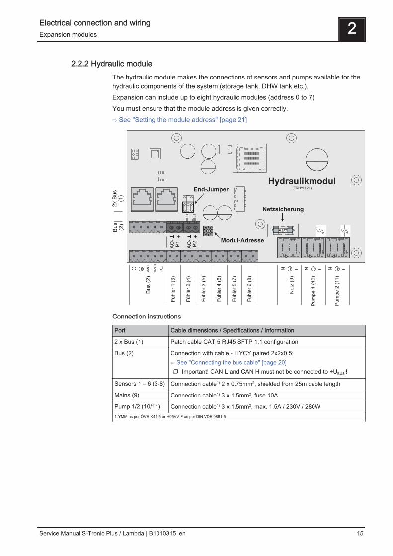
2.2.2 Hydraulic moduleThe hydraulic module makes the connections of sensors and pumps available for thehydraulic components of the system (storage tank, DHW tank etc.).Expansion can include up to eight hydraulic modules (address 0 to 7)You must ensure that the module address is given correctly.⇨ See "Setting the module address" [page 21]
AO
-P
1
AO
-P
2
6,3AT
Hydraulikmodul(FRHYU 21)
Bu
s (
2)
Fü
hle
r 1
(3
)
Fü
hle
r 5
(7
)
Ne
tz (
9)
Pu
mp
e 2
(11
)
Fü
hle
r 2
(4
)
Fü
hle
r 4
(6
)
Fü
hle
r 3
(5
)
Pu
mp
e 1
(1
0)
Fü
hle
r 6
(8
)
Bu
s(2
)
2x B
us
(1)
Modul-Adresse
End-Jumper
Netzsicherung
CA
N L
CA
N H
+U
Bus
N L N L N L
+ +
Connection instructions
Port Cable dimensions / Specifications / Information
2 x Bus (1) Patch cable CAT 5 RJ45 SFTP 1:1 configuration
Bus (2) Connection with cable - LIYCY paired 2x2x0.5;⇨ See "Connecting the bus cable" [page 20]❒ Important! CAN L and CAN H must not be connected to +UBUS !
Sensors 1 – 6 (3-8) Connection cable1) 2 x 0.75mm2, shielded from 25m cable length
Mains (9) Connection cable1) 3 x 1.5mm2, fuse 10A
Pump 1/2 (10/11) Connection cable1) 3 x 1.5mm2, max. 1.5A / 230V / 280W1.YMM as per ÖVE-K41-5 or H05VV-F as per DIN VDE 0881-5
Electrical connection and wiring 2Expansion modules
Service Manual S-Tronic Plus / Lambda | B1010315_en 15

Connecting an isolating valveIf an isolating valve is connected to a speed-controlled pump outlet, an RC elementmust be used.Furthermore, the minimum speed for the pump outlet in use must be set to 100% inthe boiler control system.
Connection example:
The outer cable L(bn) should be connected to the outer cable of the respective mainssupply of the module or to the core module, HCP0/burner relay output at pin “LV”.
2 Electrical connection and wiringExpansion modules
16 Froling GesmbH | A-4710 Grieskirchen, Industriestraße 12 | www.froeling.com

Connecting a high efficiency pump to the hydraulic moduleWire the high efficiency pump as shown in the connection diagram below:
❒ Connect the power supply for the high efficiency pump to output "Pump 1" or"Pump 2" of the hydraulic module
❒ Connect the PWM cables of the high efficiency pump to the corresponding port"AO-P1" or "AO-P2"➥ Make sure that the cables are configured correctly (polarity) in accordance with
the connection diagram of the pump! IMPORTANT! When using a Froling pump assembly:⇨ See "Connection diagrams according to pump types" [page 22]
Electrical connection and wiring 2Expansion modules
Service Manual S-Tronic Plus / Lambda | B1010315_en 17

2.2.3 Return mixer moduleThe return mixer module provides the connection for a return mixer. The relevantsensor is the return sensor on the core module. If this module is used, the “Returnflow mixer through external module” parameter must be set to “YES”.⇨ See "Setting the system type" [page 25]
Connection instructions
Port Cable dimensions / Specifications / Information
Bus (1) Connection with enclosed patch cable 0.5m
2 x mains (2) Connection cable1) 3 x 1.5mm2,
Return mixer (3) Connection cable1) 4 x 0.75mm2, max. 0.15A / 230V1.YMM as per ÖVE-K41-5 or H05VV-F as per DIN VDE 0881-5
Connection example
2 Electrical connection and wiringExpansion modules
18 Froling GesmbH | A-4710 Grieskirchen, Industriestraße 12 | www.froeling.com

Connection diagram
Disconnect already existingmains cable at core moduleand connect it at return mixermodule
Retu
rn
mix
er
mo
du
le(F
RR
LA
10)
Plug
Mains
Main switch
Connect return mixermodule and core modulewith bus cable
Use deliverd mains cablefor connection with coremodule
Return mixer
Return sensor
Co
re
mo
du
le
Electrical connection and wiring 2Expansion modules
Service Manual S-Tronic Plus / Lambda | B1010315_en 19

2.2.4 Connecting the bus cableFor the bus connections between the individual modules, cable type LIYCY paired 2x2x0.5 should be used. The connection to the 5-pin plugs should becarried out according to the following diagram:
+UBUS
CAN H
CAN L
+UBUS
CAN H
CAN L
Braided shield
White
Green
Yellow
Brown
Braided shield
White
Green
Yellow
Brown
2.2.5 Connect the patch cable to the bus plugTo connect a patch cable to a RJ45 bushing and a 5-pin plug, follow the connectiondiagram below:
2.2.6 Setting end jumpersTo ensure smooth running of the bus system, the jumper must be placed on the lastmodule.
End jumper not set End jumper set
If the contacts at the base of the end jumper are not bridged (image left), it is referredto as “not set". In this case there is no bus termination. If the contacts are closed(image right), the end jumper is set and the bus connection is terminated.
2 Electrical connection and wiringExpansion modules
20 Froling GesmbH | A-4710 Grieskirchen, Industriestraße 12 | www.froeling.com

2.2.7 Setting the module addressFor hydraulic modules or heating circuit modules it is necessary to set the requiredorder with the module addresses. The first board of a module type should always havethe address 0, so that the standard hydraulic systems set do not have to besubsequently configured. For further module types ascending module addresses(address 1 - 7) are set.
Module address set
Heating circuitmodule
Hydraulic module
Heating circuit Sensor Pump
0 03 – 04 0.1 – 0.6 0.1 – 0.2
1 05 – 06 1.1 – 1.6 1.1 – 1.2
2 07 – 08 2.1 – 2.6 2.1 – 2.2
3 09 – 10 3.1 – 3.6 3.1 – 3.2
4 11 – 12 4.1 – 4.6 4.1 – 4.2
5 13 – 14 5.1 – 5.6 5.1 – 5.2
6 15 – 16 6.1 – 6.6 6.1 – 6.2
7 17 - 18 7.1 – 7.7 7.1 – 7.2
Electrical connection and wiring 2Expansion modules
Service Manual S-Tronic Plus / Lambda | B1010315_en 21

2.3 Connection diagrams according to pump typesThree different pump types are used in all depending on the pump assembly used:
WILO Stratos Para WILO Stratos TEC WILO Yonos Para
Either a 2-pin control cable (WILO Stratos TEC, WILO Yonos Para) or a 4-pin control cable (WILO StratosPara) is used for the connection depending on the pump type. Please follow the connection instructions belowfor the wiring depending on the pump type used:
Pump type with 2-pin control cable
Power supply 2-pin control cable
(brown) L
(blue) N
(yellow-green) PE
Wire the power supply to thepump outlet on the board
Connect the control cable to the board’s PWMoutput, making sure that the polarity is correct:- blue wire to earth- brown wire to plus
Pump type with 4-pin control cable
Power supply 4-pin control cable
(brown) L
(blue) N
(yellow-green) PE
Wire the power supply to thepump outlet on the board
Connect the control cable to the board’s PWMoutput, making sure that the polarity is correct:- brown wire to earth- white wire to plusDo not use the other two wires (blue, black) andinsulate if necessary
2 Electrical connection and wiringConnection diagrams according to pump types
22 Froling GesmbH | A-4710 Grieskirchen, Industriestraße 12 | www.froeling.com

3 Operation❒ Before the initial startup check the wiring of the pumps and mixers is correct.
⇨ See "Before switching on for the first time" [page 23]❒ Check that the connected components have maximum connected load.
⇨ See "Core module" [page 6] or ⇨ See "expansion modules" [page 14]
3.1 Before switching on for the first time
NOTICE
You should have the initial startup carried out by the authorised heating engineerfrom Froling customer services.
3.1.1 Controller check❒ Check boards for foreign bodies (pieces of wire, washers, screws ...)❒ Carry out a wiring check:
Check for loose, uninsulated wires, which could cause a short-circuit❒ Check plug configuration of pumps, mixing valves and other units, which have
NOT been prepared by Froling❒ Check the connection of the BUS cable for short-circuits❒ Check the specified addresses and terminal jumpers on the individual modules
(heating circuit modules, hydraulic modules, displays etc.)⇨ See "Setting the module address" [page 21] and⇨ See "Setting end jumpers" [page 20]
3.1.2 Check on the connected units❒ Check that all units that are used are connected correctly❒ Carry out a wiring check:
Check for loose or uninsulated wires in the terminal boxes of the pumps, mixer and switch valve, which could cause a short-circuit
3.1.3 System Check❒ Check that the main fuse for the boiler has a sufficient rated amperage (16A )
➥ If a safety overload switch is used, it should be a type with 16A.
Operation 3Before switching on for the first time
Service Manual S-Tronic Plus / Lambda | B1010315_en 23

3.2 Initial startupAfter power up and when the main switch has been switched on, the start logo isdisplayed and the controller carries out a system check.After the system check the basic display is shown. The basic display is shown asstandard, giving information about the two most important parameters, and the displaycan be adjusted individually. Basic display parameters
3.2.1 Changing the operating levelFor safety reasons individual parameters are only visible at specific operating levels.To change to another level it is necessary to enter the relevant user code:
repeatedly
repeatedly
Operating level Description
Child lock(Code 0)
At "Child lock" level, only the basic display is shown.It is not possible to change parameters at this level.
Customer(Code 1)
Standard level for normal operation of the controller. All customer-specific parameters are displayed and can be changed.
Installer / Service Releases parameters to adjust the controller to the system components(if configured). All the parameters shown in these operating instructionsare available.
3 OperationInitial startup
24 Froling GesmbH | A-4710 Grieskirchen, Industriestraße 12 | www.froeling.com

3.2.2 Setting the system typeNOTICE! Only for trained personnel – installer code must be entered.
repeatedly
Boiler type
Warning! Incorrect settings can lead to faults.Continue with the DOWN arrow key
DO NOT SELECTS1 Turbo
S3 Turbo / ECO
S4 TurboSP DualFHG Turbo 3000 20:FHG Turbo 3000 70P1 Pellet 7 - 20Pellet boiler P2 – 10:Pellet boiler P2 – 25P4 Pellet 8 – 25P4 Pellet 32 - 105Turbomatic 25 – 55Turbomatic 70 – 100T4 24 – 75T4 90 – 150TX 150TX 200 – 250Wood boiler F2 22/30
DO NOT SELECT!
Boiler type parameters
Lambda probe installed YES
Actuators installed YES
Bypass pump installed NO
Return mixer using HC1 NO
Return mixer using external mixer module NO
Operation 3Initial startup
Service Manual S-Tronic Plus / Lambda | B1010315_en 25

System selection
Hydraulic System 0Hydraulic system 1Hydraulic system 2Hydraulic system 3Hydraulic System 4
SELECTFor description see “S-Tronic Plus EnergySystems” brochure
Hydraulic system for S3 boiler SELECT
Hydraulic System 12Hydraulic System 13
SELECTFor description see “S-Tronic Plus EnergySystems” brochure
Variant 1Variants 2 and 5Variant 3Variant 4
Multiple house diagrams
Slave boiler for boiler sequence control Only for systems in the cascade!
Hydraulic System
DHW tank system DHW tank 01 installed:DHW tank 08 installed
YES / NO:
YES / NO
Heating system Heating circuit 01 installedRemote control 01 installed:Heating circuit 18 installedRemote control 18 installed
YES / NOYES / NO
:YES / NOYES / NO
Solar system Solar collector 01 installed YES / NO
❒ The “remote control XX installed” parameter should be set to “YES” ifany of the three remote controls shown is used for the respective heating circuit.
Boiler remote control
Remote control of the boiler can be activated NO
❒ This menu item or parameter is only relevant for systems equipped with touchcontrol and also use the internet portalfroeling-connect.com!
3 OperationInitial startup
26 Froling GesmbH | A-4710 Grieskirchen, Industriestraße 12 | www.froeling.com

3.2.3 Before heating up for the first time❒ Check the system pressure of the heating system❒ Check that the heating system is fully ventilated❒ Check that the safety devices are present and working correctly❒ Check that there is sufficient ventilation in the boiler room❒ Check the seal of the boiler
➥ All doors and inspection openings must be tightly sealed! ❒ Door switch is working correctly
Digital inputs
Drives❒ Check that drives and actuators are working and turning in the right direction
Analogue outputs and Digital outputs
3.3 Heating up the boilerWhen starting up for the first time ensure that the combustion chamber heats upslowly. Information on safety and implementation in the operating instructions of theboiler must be observed.NOTICE! See chapter on Initial Startup in the assembly instructions of the boiler
3.3.1 Heating up
Item Description
1 When the insulated door is opened the status, "Door open", is shown on the displayand the basic display is replaced by the flue gas temperature and the parameter "IDfan". The parameter is automatically set to "ON" and the ID fan is activated atmaximum speed.
2 The ID fan can be switched on and off with the arrow keys.NOTICE! When igniting the paper, it is advisable to turn off the induced draught fanand to turn it on again afterwards.
▪ Fill the boiler with fuel and ignite it following the boiler operating instructions
3 After closing the insulated door the boiler switches automatically to "Heating up"status. The S-Tronic Lambda activates the induced draught at 100%.
4 When a specific minimum flue gas temperature is reached or when the specifiedmaximum heating up time has elapsed, the boiler changes to "Heating" status. TheS-Tronic Lambda controls the combustion according to the boiler setpoints that havebeen set.
5 If the criteria for "Heating" status are not reached within a specified time, the boilerswitches to "Off" status.
Door open 08:00
Boiler 25 °C
ID Fan ON
Door open 08:00
Boiler 25 °C
ID Fan OFF
Heating up 08:01
Boiler 25 °C
Flue gas 26 °C
Heating 08:15
Boiler 60 °C
Flue gas 180 °C
1
2
3
4
Off 09:35
Boiler 30 °C
Flue gas 38 °C5
Operation 3Initial startup
Service Manual S-Tronic Plus / Lambda | B1010315_en 27

3.4 Operating statusesThe different operating statuses are displayed at the top left of the visual display:
Heating up Boiler status during the heating up process up to a certain minimum fluegas temperature. Blower fan to 100%.
Heating The boiler controller controls combustion according to the boilersetpoints
Slumber Very low power consumption.When the boiler temperature setpoint is exceeded by a specified value,the boiler goes to "Slumber" status. The blower fan stops. If the temperature falls below the boiler temperature setpoint, the boilergoes back to “heating" status.
Door open The insulated door is open and the blower fan runs at maximum speed.
Off The boiler burns down to residual embers.
Fault WARNING - There is a fault!Troubleshooting
3 OperationOperating statuses
28 Froling GesmbH | A-4710 Grieskirchen, Industriestraße 12 | www.froeling.com

4 Menu overview and parameters
4.1 Heating
4.1.1 Heating - Status
Basic display Heating Heating
circuit 1 State
Control heating circuit according to program (NO -> heating circuit is switched off) YES
▪ YES: The heating circuit is operated according to the selected heating times.▪ NO: Heating circuit is completely switched off, frost protection remains active!
Actual flow temperature 46°C
Shows the current flow temperature.
Flow temperature setpoint 52°C
Shows the calculated flow temperature setpoint.
Room temperature 20°C
Prerequisite: Heating circuit used in conjunction with remote controlShows the current room temperature.
Override switch Auto
Prerequisite: Heating circuit used in conjunction with remote controlShows the current heating circuit mode:▪ Party: party mode; the current or next setback program is ignored▪ Setback: setback mode; the heating phases are ignored▪ Auto: automatic mode: heating phases according to the set heating times▪ Off: switched-off; heating circuit deactivated, only frost protection!
Outside air temperature 2°C
Shows the current external temperature.
Menu overview and parameters 4Heating
Service Manual S-Tronic Plus / Lambda | B1010315_en 29

4.1.2 Heating - Temperatures
Basicdisplay Heating Heating
circuit 1 Temperatures
Desired room temperature during heating mode 20°C
Prerequisite: Heating circuit used in conjunction with remote controlRoom temperature which is regulated during the set heating times
Desired room temperature during setback mode 16°C
Prerequisite: Heating circuit used in conjunction with remote controlRoom temperature which is regulated outside of the set heating times
Flow temperature SP at external temperature of +10°C 40°C
First setting point for definition of heating curve
Flow temperature SP at external temperature of -10°C 60°C
Second setting point for definition of heating curve
Controller gain room temperature Kp-Rm 6.0
Prerequisite: Heating circuit used in conjunction with remote controlInfluencing factor of room temperature on the flow temperature of the heating circuit. If there is a deviation inthe room temperature of +/- 1°C the set value of the flow temperature is corrected by this value. (Only in con‐junction with remote control)Recommended values:▪ Floor heating: 2-3▪ Radiators (new build): 4-5▪ Radiators (old build): 6-7NOTICE! Observe external influences on the remote control!
Reduction of flow temperature in setback mode 15°C
The flow temperature is reduced by this value during setback mode.
External temperature below which the heating circuit pump switches on in heating mode 18°C
If the external temperature exceeds this value during heating, the heating circuit pumps and mixing valve aredeactivated.
4 Menu overview and parametersHeating
30 Froling GesmbH | A-4710 Grieskirchen, Industriestraße 12 | www.froeling.com

External temperature below which the heating circuit pump switches on in setback mode 7°C
If the external temperature falls below this value in setback mode, the heating circuit pumps and mixing valveare activated.
Maximum heating circuit flow temp. 75°C
Maximum temperature for limiting outfeed temperature at which the heating circuit is supplied.
Maximum DHW tank flow temp. 75°C
If DHW tank 1 is supplied directly from heating circuit 1, you can limit the maximum flow temperature for theduration of DHW tank loading.
Frost protection temperature 10°C
If the room temperature or the flow temperature is lower than the set value, the heating circuit pump will beswitched on and the heating circuit mixer keeps to the maximum heating circuit flow temperature that is set.
Menu overview and parameters 4Heating
Service Manual S-Tronic Plus / Lambda | B1010315_en 31

4.1.3 Heating - Service
Basicdisplay Heating Heating
circuit 1 Service
Heating circuit pump A 0
Used for testing the pump output:▪ A 0: Automatic, Off; A 1: Automatic, On▪ 1: Manual, On▪ 0: Manual, Off
Heating circuit mixing valve OPEN A 0
Used for testing the mixing valve output:▪ A 0: Automatic, Off; A 1: Automatic, On▪ 1: Manual, On▪ 0: Manual, Off
Heating circuit mixing valve CLOSED A 0
Used for testing the mixing valve output:▪ A 0: Automatic, Off; A 1: Automatic, On▪ 1: Manual, On▪ 0: Manual, Off
Mixer runtime 240 s
Here you can set the mixer runtime of the mixer in use.NOTICE! To avoid mixer vibration, do not set value < 150s!
Switch off heating circuit pump when flow setpoint is lower than 20°C
Prerequisite: Heating circuit is operated without remote controlIf a flow temperature setpoint is calculated below the value set, the heating circuit pump switches off the heat‐ing circuit pump and the mixing valve closes.
Should this heating circuit heat when there is DHW tank priority? NO
▪ NO: During DHW tank loading this heating circuit is deactivated.▪ YES: Despite active DHW tank priority, this heating circuit is supplied with heat during DHW tank loading.
4 Menu overview and parametersHeating
32 Froling GesmbH | A-4710 Grieskirchen, Industriestraße 12 | www.froeling.com

From which buffer tank or distributor is the heating circuit supplied (0 = boiler) 1
Prerequisite: Parameter can only be used in conjunction with multiple house systems (variants)This parameter defines the allocation of the heat source for this heating circuit:▪ 0 = boiler▪ 1 = buffer tank 01, …
High temperature requirement because of DHW tank 1 loading NO
▪ NO: The heating circuit is operated according to the selected heating curve.▪ YES: Loading of DHW tank from the heating circuit. If there is a requirement from the DHW tank and the
criteria for DHW tank loading have been met, the isolating valve immediately clears the way for boilerloading. The heating circuit pump starts running as soon as the “Load if temperature differencebetween boiler and DHW tank is” criterion is reached. Once DHW tank loading is complete, theheating circuit pump will stop, the isolating valve will remain active for a specified period of time and theheating circuit mixer will close. If time has run out, the heating circuit will go back to being supplied on aweather-compensated basis.
Parameter only available with “heating circuit 1” and generally only used in conjunction with the unit model ofthe PE1 Pellet pellet boiler!
High temperature requirement because of DHW tank loading NO
▪ NO: The heating circuit is operated according to the selected heating curve.▪ YES: The heating circuit is operated according to the selected heating curve. Whilst the DHW tank is
loading, the heating circuit is operated at a higher temperature for the duration of the DHW tank loading.Once the DHW tank is loaded, the heating circuit is supplied again according to the heating curve.
NOTICE! Parameters for “heating circuit 2” only!
For high temperature requirement don't look at DHW tank 1 NO
▪ NO: DHW tank 1 is not supplied with heat from the lines of heating circuit 2.▪ YES: DHW tank 1 is supplied with heat from the lines of heating circuit 2 and requires a higher temperature
for the duration of the DHW tank loading.
Menu overview and parameters 4Heating
Service Manual S-Tronic Plus / Lambda | B1010315_en 33

4.1.4 Heating - Heating up program
Basicdisplay Heating Heating up
program Service
Heating up program active NO
▪ NO: Heating up program deactivated, all heating circuits are operated according to the selected heatingtimes.
▪ YES: The 30-day program that has been set starts. After the 30 days, the heating circuit that has beenselected operates based on the set heating times again.
▪ The heating times of the selected heating circuit, as well as the boiler/buffer tank loading times areautomatically set to 0:00-24:00 and the external temperature heating limit is ignored.
▪ When using a firewood boiler, a corresponding heat supply must be ensured.▪ If the current room temperature falls below the set frost protection temperature, this influences the set flow
temperature setpoint of the heating up program.NOTE: Only in conjunction with remote control!
Current day of the heating up program 1
Shows the current day of the heating up program that is running. By adjusting this parameter, you can jumpforward or return to a specific day of the program.
Which heating up program is used 1
There are set options for the progression of the flow temperature in heating up programs 1 – 6. With heating upprogram 7 the flow temperature can be selected freely over the entire 30 days.Heating up program 8 allows you to pre-define the progression of the flow temperature for each individual day.
Outfeed setpoint for all days in program 7 35°C
If heating up program 7 is active, the selected heating circuit is adjusted to the specified flow temperature.
4 Menu overview and parametersHeating
34 Froling GesmbH | A-4710 Grieskirchen, Industriestraße 12 | www.froeling.com

Heating up programs
Heating up program 1:
0
5
10
15
20
25
30
35
40
45
50
55
1 6 11 16 21 26
Day
Flo
wte
mp
.setp
oin
t[°
C]
30
Heating up program 2:
0
5
10
15
20
25
30
35
40
45
50
1 6 11 16 21 26
Day
Flo
wte
mp
.setp
oin
t[°
C]
30
Heating up program 3:
0
5
10
15
20
25
30
35
40
45
50
1 6 11 16 21 26
Day
Flo
wte
mp
.setp
oin
t[°
C]
30
Heating up program 4:
0
5
10
15
20
25
30
35
40
45
1 6 11 16 21 26
Day
Flo
wte
mp
.setp
oin
t[°
C]
30
Heating up program 5:
0
5
10
15
20
25
30
35
40
45
50
55
1 6 11 16 21 26
Day
Flo
wte
mp
.setp
oin
t[°
C]
30
Heating up program 6:
0
5
10
15
20
25
30
35
40
45
50
55
60
1 6 11 16 21 26
Day
Flo
wte
mp
.setp
oin
t[°
C]
30
Heating up program 7:
0
5
10
15
20
25
30
35
40
1 6 11 16 21 26
Day
Flo
wte
mp
.setp
oin
t[°
C]
30
The heating up programs listed are non-bindingrecommendations. If the heating up program is to beused for floor screed drying, you must consult themanufacturer of the floor finish and/or the installer!
Menu overview and parameters 4Heating
Service Manual S-Tronic Plus / Lambda | B1010315_en 35

Configure program 8
Basicdisplay Heating Heating up
program Service Configureprogram 8
Outfeed temperature setpoint on day 1 0°C
Outfeed temperature setpoint on day 2 0°C
: :
Outfeed temperature setpoint on day 30 0°C
If “heating up program 8” is selected, the flow temperature setpoint can be preset for each day using this set‐ting.
Heating circuits used
Basic display Heating Heating up
program ServiceHeating circuitsused
Use heating circuit 01 NO
Use heating circuit 02 NO
: :
Use heating circuit 18 NO
The number of heating circuits used depends on the system configuration. If only 2 heating circuits are instal‐led, then only 2 heating circuits will be available for selection. The heating up program selected will be used for all heating circuits!
4 Menu overview and parametersHeating
36 Froling GesmbH | A-4710 Grieskirchen, Industriestraße 12 | www.froeling.com

4.1.5 Heating - General settings
Basic display Heating General settings
Correction value for external sensor 0°C
If the outside temperature sensor shows an incorrect value, the value can be adjusted using this parameter.
Heating circuit module to which the external sensor is connected (0 = core module) 0
If the outside temperature sensor is not connected to the core module, the address of the relevant heating cir‐cuit module +1 must be set here. (Sensor 1 on relevant module)
Use room temperature sensor input for room thermostat NO
NOTICE! This parameter influences all sensor connections which an analogue room sensor can be connectedto!▪ NO: At the sensor connector of the room sensor, a room sensor must be connected to control the room
temperature.▪ YES: At the sensor connector of the room sensor, room thermostats can be connected to control the room
temperature.▪ Contact of room thermostat open: Heating circuit pump deactivated, mixing valve is closed▪ Contact of room thermostat closed: Heating circuit pump and mixer control active
Menu overview and parameters 4Heating
Service Manual S-Tronic Plus / Lambda | B1010315_en 37

4.2 Water
4.2.1 Water - Status
Basic display Water State
DHW tank top temperature 58°C
Current temperature of the DHW tank. The DHW tank is heated when the time window for the DHW tank load‐ing is reached and the current temperature of the DHW tank has fallen below the value using the parameter“Reload if DHW tank temperature is below”. A loading of the DHW tank takes place when eitherthe time window has elapsed or the temperature value which is set under “Set DHW temperature” isreached.
DHW tank bottom temperature 55°C
Prerequisite: Solar panel system is regulated by Froling!Current temperature in the area of the reference sensor of the solar panel system.
DHW tank pump control 0%
Specifies the speed of the DHW tank pump as a percentage of maximum speed.
4 Menu overview and parametersWater
38 Froling GesmbH | A-4710 Grieskirchen, Industriestraße 12 | www.froeling.com

4.2.2 Water - Temperatures
Basic display Water Temperatures
Set DHW temperature 58°C
When this DHW temperature is reached, DHW tank loading is stopped.
Reload if DHW tank temperature is below 45°C
If the DHW tank temperature falls below the value set here, the time window is active and the loading source(boiler or buffer tank) indicates the set loading increase, and the DHW tank loading is started.
Load if temperature difference between buffer tank and DHW tank is 6°C
When the buffer tank top temperature is above the current DHW tank temperature by this value and the timewindow is active, the DHW tank loading is started. (Only for systems with buffer tanks)
Load if temperature difference between boiler and DHW tank is 6°C
When the boiler temperature is above the current DHW tank temperature by this value and the time window isactive, the DHW tank loading is started. (Only for systems with buffer tanks)
Setpoint for temperature difference between boiler and DHW tank 10°C
Adjusting the boiler temperature setpoint to reach the desired DHW tank temperature.Boiler temperature setpoint = Set DHW temperature + differenceIf the current boiler temperature setpoint calculated is higher than the result from the above calculation, theboiler temperature setpoint is maintained. (Only for systems without buffer tank)
Menu overview and parameters 4Water
Service Manual S-Tronic Plus / Lambda | B1010315_en 39

4.2.3 Water - Service
Basic display Water Service
DHW tank 1 pump will be controlled from HCP0 NO
Prerequisite: Hydraulic system for S3 Turbo▪ NO: The HKP0 output switches to the parameter “Heating circuit release from followingbuffer tank temperature”.
▪ YES: The DHW loading pump is controlled via the HKP0 output, the DHW tank sensor must be connectedto the “Return sensor” sensor input.
NOTICE! The DHW tank can only be loaded using HCP0 if the return temperature control is not performed bythe mixing valve.
Residual heat use NO
Prerequisite: Hydraulic system 0 and return temperature control with mixing valve▪ YES: Diverts the residual energy to the DHW tank, the “Minimum boiler temperature to releaseall pumps” parameter is ignored. The pump set to minimum speed until the boiler temperature is lowerthan the DHW tank temperature + 3°C.
Only load DHW tank once a day NO
▪ NO: A DHW loading takes place always when the DHW tank temperature falls below the value, which is setunder “Reload if DHW tank temperature is below”, and the time window is active and the heatsource (boiler or buffer tank) indicates sufficient temperature.
▪ YES: If the DHW tank has already been loaded once on the current day, a further DHW tank loading isprevented.
Legionella heating activated YES
▪ NO: A legionella heating of the DHW tank is not carried out.▪ YES: The DHW tank is heated to the temperature once a week, which is set under the parameter “DHW
tank temp. setpoint for legionella heating (same for all DHW tanks)”.
Which day for legionella heating MO
Day of the week on which the Legionella heating is carried out.
DHW tank temp. setpoint for legionella heating (same for all DHW tanks) 65°C
If the parameter “Legionella heating activated” is set to “YES”, the DHW tank is heated to the set temperatureon the specified day of the week.
Which buffer tank or heat distributor supplies the heat to this DHW tank (0 = boiler) 1
Prerequisite: Parameter can only be used in conjunction with multiple house systems (variants)
4 Menu overview and parametersWater
40 Froling GesmbH | A-4710 Grieskirchen, Industriestraße 12 | www.froeling.com

This parameter defines the allocation of the heat source for this DHW tank:▪ 0 = Boiler▪ 1 = buffer tank 01, …
DHW tanks run-on (this parameter applies for all DHW tanks) 0 min
When DHW tank loading has finished, the DHW tank loading pumps continue to run for the time set here.
Which sensor is used for top DHW tank 1 0.3
Sensor input to which the DHW tank sensor is connected.
Which sensor is used for bottom DHW tank 1 0.4
Sensor input to which the sensor for the DHW tank solar reference is connected.
Which pump is used for DHW tank 1 0.2
Pump outlet to which the boiler loading pump is connected.
PWM setting for DHW tank pump Normal pump
Definition of control signal for pump type used.⇨ See "PWM / 0 - 10V settings" [page 102]
Minimum DHW tank speed 45%
Adjustment of the minimum speed to the pump type. (Set the pump mode according to pump manufacturer’sinstructions)
Maximum DHW tank pump speed 100%
If you need to limit the maximum speed of the boiler loading pump for systemic reasons, you can do so byadjusting this parameter.
Menu overview and parameters 4Water
Service Manual S-Tronic Plus / Lambda | B1010315_en 41

4.3 Solar
4.3.1 Solar - Status
Basic display Solar State
Collector temperature 80°C
Display of the current temperature at the solar collector.
Top storage tank solar sensor 67°C
Shows the current temperature at the solar reference sensor in the top part of the buffer tank.
Solar temperature buffer tank bottom 43°C
Shows the current temperature at the solar reference sensor in the lower part of the buffer tank.
Collector return temperature 50°C
Prerequisite: Hydraulic System 12 or Hydraulic System 13Display of the current temperature at the collector return.
Actual power from solar heat meter [kW] 0.00
Display of the current output which is generated by the solar collector. The calculation of the output is onlyperformed either when a per litre output of the collector pump has been set or an external volume pulse trans‐mitter is used. In order to perform the calculation more precisely, the use of a collector return feed sensor isrecommended.
Flow through [l/h] 0l
Prerequisite: External volume pulse transmitter installedDisplay of the water quantity currently being pumped through the solar collector.
Todays yield [kWh] 0
Display of the heat quantity that has been supplied by the solar panel system today.
Total yield [kWh] 0
Display of the heat quantity which has been supplied by the solar panel system since activation of the heatmeter.
DHW tank bottom temperature 55°C
Current temperature in the area of the reference sensor of the solar panel system.
4 Menu overview and parametersSolar
42 Froling GesmbH | A-4710 Grieskirchen, Industriestraße 12 | www.froeling.com
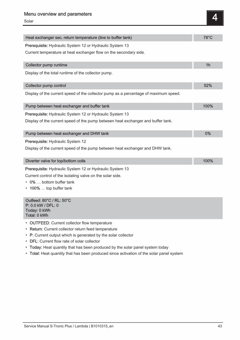
Heat exchanger sec. return temperature (line to buffer tank) 78°C
Prerequisite: Hydraulic System 12 or Hydraulic System 13Current temperature at heat exchanger flow on the secondary side.
Collector pump runtime 1h
Display of the total runtime of the collector pump.
Collector pump control 52%
Display of the current speed of the collector pump as a percentage of maximum speed.
Pump between heat exchanger and buffer tank 100%
Prerequisite: Hydraulic System 12 or Hydraulic System 13Display of the current speed of the pump between heat exchanger and buffer tank.
Pump between heat exchanger and DHW tank 0%
Prerequisite: Hydraulic System 12Display of the current speed of the pump between heat exchanger and DHW tank.
Diverter valve for top/bottom coils 100%
Prerequisite: Hydraulic System 12 or Hydraulic System 13Current control of the isolating valve on the solar side.▪ 0% … bottom buffer tank▪ 100% … top buffer tank
Outfeed: 80°C / RL: 50°CP: 0.0 kW / DFL: 0Today: 0 kWhTotal: 0 kWh
▪ OUTFEED: Current collector flow temperature▪ Return: Current collector return feed temperature▪ P: Current output which is generated by the solar collector▪ DFL: Current flow rate of solar collector▪ Today: Heat quantity that has been produced by the solar panel system today▪ Total: Heat quantity that has been produced since activation of the solar panel system
Menu overview and parameters 4Solar
Service Manual S-Tronic Plus / Lambda | B1010315_en 43

4.3.2 Solar - Temperatures
Basic display Solar Temperatures
Boiler target temperature during solar charging 75°C
Up to this temperature the DHW tank is heated by the solar system If the solar panel system is equipped withan isolating valve for switching between DHW tank and buffer solar element, then this parameter is responsiblefor switching between both of these solar elements.
Temp differential to start collector pump 10°C
The collector pump activates when the collector temperature exceeds the reference temperature in the DHWtank or buffer tank by this value.
Temp difference to stop collector pump 5°C
The collector pump switches off when the difference between the collector temperature and reference temper‐ature in the DHW tank or buffer tank is lower than this value.
Maximum buffer tank bottom temperature during solar charging 85°C
If the sensor for the solar reference temperature in the buffer tank exceeds the specified value, the collectorpump is switched off.NOTICE! This parameter is only relevant for systems used in conjunction with a buffer tank!
Minimum collector temperature 20°C
Minimum temperature at collector which must be reached in order for the solar control to start.
Heat exchanger - buffer tank pump start delay 120s
Delay for switching on the pump between heat exchanger and buffer tank.NOTICE! This parameter is displayed only when hydraulic system 12 or 13 is set.
Heat exchanger – buffer tank pump stop delay 240s
Delay for switching off the pump between heat exchanger and buffer tank.NOTICE! This parameter is displayed only when hydraulic system 12 or 13 is set.
Buffer tank top solar setpoint (fast loading until this temperature) 60°C
When the upper sensor in the buffer tank reaches the specified value, the solar isolating valve switches to thelower area of the buffer tank.NOTICE! This parameter is displayed only when hydraulic system 12 or 13 is set.
4 Menu overview and parametersSolar
44 Froling GesmbH | A-4710 Grieskirchen, Industriestraße 12 | www.froeling.com
Collector - buffer tank top differential 20°C
This is the overcharge for the collector pump controller for the top or bottom temperature in the buffer tank.NOTICE! This parameter is displayed only when hydraulic system 12 or 13 is set.
Top buffer tank – secondary HE flow difference 10°C
This parameter specifies how much the heat exchanger secondary outfeed temperature should be below thecollector temperature. If the difference is less than the set value, the speed of the pump between heat ex‐changer, DHW tank and buffer tank is reduced.NOTICE! This parameter is displayed only when hydraulic system 12 or 13 is set.
Collector return - buffer tank bottom differential 20°C
The temperature at the reference sensor in the bottom buffer tank plus the set value produces the desired tem‐perature of the collector return.NOTICE! This parameter is displayed only when hydraulic system 12 or 13 is set.
Menu overview and parameters 4Solar
Service Manual S-Tronic Plus / Lambda | B1010315_en 45

4.3.3 Solar - Service
Basic display Solar Service
Solar system 1
▪ 1: The solar panel system supplies only the DHW tank▪ 2: The solar panel system supplies only the buffer tank▪ 3: The solar panel system is expanded with a switch valve and is used to supply two different heat sinks.
For example: Switch from domestic hot water tank to buffer tank, or between top and bottom solar elementswith the hygienic solar layered tank or modular solar layered tank with 2 solar elements)
NOTICE! This parameter is not displayed when hydraulic system 12 or 13 is set.
Which pump is used for the solar collector 1.1
Pump outlet to which the collector pump is connected.
PWM setting for solar collector pump Normal pump
Definition of control signal for pump type used.⇨ See "PWM / 0 - 10V settings" [page 102]
Minimum collector pump speed 45%
Adjustment of the minimum speed to the pump type. (Set the pump mode according to pump manufacturer’sinstructions)
Maximum collector pump speed 100%
If you need to limit the maximum speed of the collector pump for systemic reasons, you can do so by adjustingthis parameter.
Collector monitoring NO
If this parameter is active the collector pump is switched on at regular intervals for 10 seconds. The time canbe defined using the following parameter. If the collector sensor detects an increase in temperature, the pumpis kept on. This function is active from 10:00am - 7:00pm and the threshold value of the collector temperature,from which this function is active, is dynamically adjusted.
Collector monitoring every 30 min
If the collector pump is not active within the time window between 10:00am – 19:00pm, this is activated for 10seconds at the end of the specified time set here. If the collector sensor detects an increase in temperature,the pump is kept on. If no temperature increase on the collector sensor is detected, the collector pumpswitches off and the time starts to run afresh.
4 Menu overview and parametersSolar
46 Froling GesmbH | A-4710 Grieskirchen, Industriestraße 12 | www.froeling.com
For solar to buffer and DHW tank, the DHW tank has priority YES
YES: The DHW tank is loaded until the temperature is reached, which is set under „Set DHW temperatureduring solar charging”, and only then switched to the buffer tank by means of the switch valve.NO: The DHW tank is charged until the temperature difference between the sensor on the solar collector andthe solar reference sensor in DHW tank is no longer sufficient. The isolating valve then switches to the bufferthank and supplies it for 20 minutes. Afterwards the collector pump is stopped for 20 minutes and a check iscarried out to see if the temperature difference is now sufficient for DHW tank charging.
Solar charging to which buffer tank 1
This parameter defines the buffer tank to which the solar charging takes place.
Solar charging to which DHW tank 1
This parameter defines the DHW tank to which the solar charging takes place.
Which sensor is used for the solar collector 1.1
Sensor input to which the collector sensor is connected.
Which sensor is used for top storage tank solar reference 0.1
Sensor input to which the solar reference sensor in the top part of the buffer tank is connected.
Which sensor is used for bottom storage tank solar reference 0.2
Sensor input to which the solar reference sensor in the lower part of the buffer tank is connected.
Which sensor is used for the heat exchanger sec. flow? 1.4
Prerequisite: Hydraulic System 12 or Hydraulic System 13Sensor input to which the sensor at heat exchanger flow on the secondary side is connected.
Which sensor is used for the collector return 1.5
Sensor input to which the sensor for the collector return is connected.
Which pump is used for the solar isolating valve 1.2
Pump outlet to which the solar isolating valve is connected.
Which pump is used for buffer tank - heat exchanger 2.1
Prerequisite: Hydraulic System 12 or Hydraulic System 13Pump outlet to which the pump between the solar heat exchanger and buffer tank is connected.
Menu overview and parameters 4Solar
Service Manual S-Tronic Plus / Lambda | B1010315_en 47

PDM setting for the buffer tank - heat exchanger pump Normal pump
Prerequisite: Hydraulic System 12 or Hydraulic System 13Definition of control signal for pump type used.⇨ See "PWM / 0 - 10V settings" [page 102]
Which pump is used for DHW tanks - heat exchanger 2.2
Prerequisite: Hydraulic System 12Pump outlet to which the pump between the solar heat exchanger and DHW tank is connected.
PDM setting for the DHW tank - heat exchanger pump Normal pump
Prerequisite: Hydraulic System 12Definition of control signal for pump type used.⇨ See "PWM / 0 - 10V settings" [page 102]
Invert isolating valve NO
Prerequisite: Solar system 3▪ NO: The pump output, which the solar isolating valve is connected to, is supplied with 230V when the solar
panel system supplies energy to the DHW tank solar element. If there is no 230V at this output, then thevalve clears the way for the buffer solar element.
▪ YES: If the solar isolating valve switches incorrectly, the way it is controlled can be adjusted using thisparameter.
Prerequisite: “Hydraulic System 12” or “Hydraulic System 13”▪ NO: The pump output, which the solar isolating valve is connected to, is supplied with 230V when the solar
panel system supplies energy to the top part of the buffer tank. If there is no 230V at this output, then thevalve clears the way for the lower area of the buffer tank.
▪ YES: If the solar isolating valve switches incorrectly, the way it is controlled can be adjusted using thisparameter.
Is a PT1000 sensor used as a solar sensor? NO
▪ NO: A KTY81 sensor is used as a collector sensor▪ YES: A PT1000 sensor is used as a collector sensor
Collector pump control Kp value 1.00
Control parameter for the speed control of the collector pump.
Collector pumps control Tn value 300s
Control parameter for the speed control of the collector pump.
Secondary HE pumps control Kp value 0.25
Prerequisite: Hydraulic System 12 or Hydraulic System 13Control parameter for the speed control of the pump between the solar heat exchanger and buffer tank, as wellas for the pump between the solar heat exchanger and DHW tank (if installed).
Secondary HE pumps control Tn value 60s
4 Menu overview and parametersSolar
48 Froling GesmbH | A-4710 Grieskirchen, Industriestraße 12 | www.froeling.com

Prerequisite: Hydraulic System 12 or Hydraulic System 13Control parameter for the speed control of the pump between the solar heat exchanger and buffer tank, as wellas for the pump between the solar heat exchanger and DHW tank (if installed).
Minimum pump speed secondary HE 20%
Prerequisite: Hydraulic System 12 or Hydraulic System 13Adjustment of the minimum speed to the pump type. (Set the pump mode according to pump manufacturer’sinstructions)This parameter applies for the pump between the solar heat exchanger and buffer tank, as well as for thepump between the solar heat exchanger and DHW tank (if installed).
Menu overview and parameters 4Solar
Service Manual S-Tronic Plus / Lambda | B1010315_en 49

4.3.4 Solar - Heat meter
Basic display Solar Solar heat meter
Outfeed: 80°C / RL: 50°CP: 0.0 kW / DFL: 0Today: 0 kWhTotal: 0 kWh
▪ OUTFEED: Current collector flow temperature▪ Return: Current collector return feed temperature▪ P: Current output which is generated by the solar collector▪ DFL: Current flow rate of solar collector▪ Today: Heat quantity that has been produced by the solar panel system today▪ Total: Heat quantity that has been produced since activation of the solar panel system
Collector temperature 80°C
Display of the current temperature at the solar collector.
Collector return temperature 50°C
Prerequisite: Hydraulic System 12 or Hydraulic System 13Display of the current temperature at the collector return.
Actual power from solar heat meter [kW] 0.00
Display of the current output which is generated by the solar collector. The calculation of the output is onlyperformed either when a per litre output of the collector pump has been set or an external volume pulse trans‐mitter is used. In order to perform the calculation more precisely, the use of a collector return feed sensor isrecommended.
Flow through [l/h] 0l
Prerequisite: External volume pulse transmitter installedDisplay of the water quantity currently being pumped through the solar collector.
Todays yield [kWh] 0
Display of the heat quantity that has been supplied by the solar panel system today.
Total yield [kWh] 0
Display of the heat quantity which has been supplied by the solar panel system since activation of the heatmeter.
4 Menu overview and parametersSolar
50 Froling GesmbH | A-4710 Grieskirchen, Industriestraße 12 | www.froeling.com

Nominal flow of collector pump for heat meter [L/h] 0l
If no external volume pulse transmitter is used, the pump of the heat meter can be activated by entering theper litre output. The flow rate at 100% collector pump speed must be entered here.NOTICE! This parameter can be ignored if using an external volume pulse transmitter.
Pulse per litre of flow through meter 2.0
If an external volume pulse transmitter is used, adjust this value according to the volume pulse transmitterused. [0.5 – 5 pulses/L]
Which sensor is used for the collector return 1.5
Sensor input to which the sensor for the collector return is connected.
Which sensor is used for heat meter flow temperature 1.1
Sensor input to which the sensor for the heat meter flow temperature is connected.
Is an external flow through counter used NO
▪ YES: An external volume pulse transmitter is in use.
Menu overview and parameters 4Solar
Service Manual S-Tronic Plus / Lambda | B1010315_en 51

4.4 Buffer tank
4.4.1 Buffer tank - Status
Basic display
Buffer tank Buffer tank 01 State
Buffer tank top temperature 67°C
Shows the current temperature in the top part of the buffer tank.
Buffer tank temperature, sensor 2 58°C
Prerequisite: Master boiler in the cascade or hydraulic system 4 or fuel amount calculationShows the current temperature in the top part of the buffer tank.
Buffer tank temperature, sensor 3 56°C
Prerequisite: Master boiler in the cascade or hydraulic system 4 or fuel amount calculationShows the current temperature in the lower part of the buffer tank.
Buffer tank middle temperature 56°C
Prerequisite: Middle buffer tank temperature sensor installedDisplay of the current temperature in the mid area of the buffer tank.
Buffer tank bottom temperature 40°C
Shows the current temperature in the lower part of the buffer tank.
Buffer tank pump control 40%
Display of the current speed of the buffer loading pump.
Buffer tank charge 65%
Prerequisite: Master boiler in the cascade or hydraulic system 4 or fuel amount calculationDisplays the current buffer tank charge.
4 Menu overview and parametersBuffer tank
52 Froling GesmbH | A-4710 Grieskirchen, Industriestraße 12 | www.froeling.com
4.4.2 Buffer tank - Temperatures
Basic display
Buffer tank Buffer tank 01 Temperatures
Heating circuit release from following buffer tank temperature 30°C
Temperature value which must be reached to release the heating circuit pumps in the top part of the buffertank.NOTICE! This parameter applies for all available heating circuits!
Buffer tank fully loaded if temperature difference between boiler and bottom buffer tank 10°C
From this difference between the boiler temperature setpoint that has been set and the current temperature inthe lower part of the buffer tank, buffer tank loading is stopped.
Buffer – Buffer difference 2°C
Prerequisite: Variant 3Difference, which must be given for loading a storage tank e.g. in an adjacent building. If this difference is notreached, the storage tank loading stops.
Buffer tank charge is 100% at boiler setpoint parameter 4°C
The buffer tank charge is 100% if the average temperature of the buffer tank is below the specified boiler set‐point temperature by the specified value. This parameter defines the end point of the charging curve of thebuffer tank to calculate the amount of fuel required to load the buffer tank.
Buffer tank charge is 0% at the following temperature (absolute value) 30°C
The buffer tank charge is 0% if the average temperature of the buffer tank reaches the specified value. Thisparameter defines the base point of the charging curve of the buffer tank.
Menu overview and parameters 4Buffer tank
Service Manual S-Tronic Plus / Lambda | B1010315_en 53
4.4.3 Buffer tank - Service
Basic display
Buffer tank Buffer tank 01 Service
Enable heating circuit pump 0 according to top buffer temp. NO
▪ NO: Release of heating circuit pump 0 according to the boiler temperatureParameter “Minimum boiler temperature to release all pumps”
▪ YES: Release of heating circuit pump 0 according to the temperature in the top part of the buffer tankParameter “Heating circuit release from following buffer tank temperature”
Residual heat use NO
Prerequisite: Return temperature control with mixing valve▪ YES: Diverts the residual energy to the buffer tank, the “Minimum boiler temperature to releaseall pumps” parameter is ignored. The pump is activated at minimum speed until the boiler temperature islower than the bottom buffer tank temperature +3°C.
Mid buffer controller active? If No the sensor is only a display NO
Prerequisite: Middle buffer tank temperature sensor installed▪ NO: The sensor in the mid area of the buffer tank is shown on the display.▪ YES: The sensor in the middle area of the buffer tank is used for the border layer loading function.
Which sensor is used for buffer tank top 0.1
Sensor input to which the sensor in the top part of the buffer tank is connected.
Which sensor is used for buffer tank sensor 2 0.4
Sensor input to which the sensor in the top part of the buffer tank is connected.
Which sensor is used for buffer tank sensor 3 0.6
Sensor input to which the sensor in the bottom part of the buffer tank is connected.
Which sensor is used for middle buffer tank 0.6
Sensor input to which the sensor in the mid area of the buffer tank is connected.
Which sensor is used for bottom buffer tank 0.2
Sensor input to which the sensor in the bottom part of the buffer tank is connected.
Which pump is used for the buffer tank 0.1
Pump outlet to which the buffer loading pump is connected.
4 Menu overview and parametersBuffer tank
54 Froling GesmbH | A-4710 Grieskirchen, Industriestraße 12 | www.froeling.com

PWM setting for buffer tank pump Normal pump
Definition of control signal for pump type used.⇨ See "PWM / 0 - 10V settings" [page 102]
Minimum buffer tank pump speed 45%
Adjustment of the minimum speed to the pump type. (Set the pump mode according to pump manufacturer’sinstructions)
Maximum buffer tank pump speed 100%
If you need to limit the maximum speed of the store loading pump for systemic reasons, you can do so by ad‐justing this parameter.
Refill calculation active (sensors have to be assigned correctly) NO
▪ YES: When opening the insulated door a recommendation message regarding the amount of fuel requiredto load up the layered tank appears on the display.
Is a hygienic layered tank used? NO
▪ YES: If a hygienic layered tank (combi tank) is used, 1/3 of the storage volume is subtracted whencalculating the amount of fuel.
Volume of the used buffer tank 2000l
The storage tank volume set here is used for calculating the required amount of fuel for loading the storagetank.
Pump outlet for buffer tank relief valve 8.1
The isolating valve switches off part of the layered tank until an adjustable temperature has been reached sothat the boiler reaches the temperature more quickly. Once this temperature has been reached, the isolatingvalve switches back and the entire volume of the layered tank is available to the boiler.
Invert pump outlet for buffer relief valve NO
▪ YES: If the valve switches incorrectly, the way it is controlled can be changed using this parameter.
Menu overview and parameters 4Buffer tank
Service Manual S-Tronic Plus / Lambda | B1010315_en 55

4.5 Boiler
4.5.1 Boiler - Status
Basic display Boiler State
Boiler temperature 25°C
Display of current boiler temperature.
Flue gas temperature 28°C
Display of the current flue gas temperature.
Flue gas setpoint 38°C
Display of the calculated flue gas setpoint.
Boiler control variable 100%
Display of the signal for the combustion controller.
ID fan control 0%
Display of the current ID fan control.
ID fan speed 0 rpm
Display of the current ID fan speed.
Primary air 0%
Shows the current value of the primary air flap according to controller.
Position of primary air flap 0%
Shows the current position of the primary air flap. (Adjusted for the air settings)
Residual oxygen content 1.9%
Displays the current residual oxygen content.
Oxygen control 0%
Secondary air 0%
Shows the current value of the secondary air flap according to controller.
4 Menu overview and parametersBoiler
56 Froling GesmbH | A-4710 Grieskirchen, Industriestraße 12 | www.froeling.com

Position of secondary air flap 0%
Shows the current position of the secondary air flap. (Adjusted for the air settings)
Sensor 1 30°C
Display of the current temperature at sensor 1.
Return sensor 28°C
Prerequisite: Return temperature control with mixing valveDisplay of the current temperature at the boiler return.
Menu overview and parameters 4Boiler
Service Manual S-Tronic Plus / Lambda | B1010315_en 57

4.5.2 Boiler - Temperatures
Basic display Boiler Temperatures
Boiler temperature setpoint 80°C
The boiler temperature is regulated to this temperature. Setting range 60 – 90°C
Shutdown if current boiler temperature is higher than boiler setpoint + 5°C
If the boiler temperature setpoint is exceeded by this value, the boiler switches to “slumber” status. The boilerstarts up again below the boiler temperature setpoint.
Always shutdown when boiler maximum setpoint is exceeded by 3°C
If the maximum boiler temperature setpoint is exceeded by this value, the heating circuit pumps, the DHW tankloading pumps and the buffer tank pump are also activated for cooling the boiler, and the boiler switches to“slumber” status. If the current boiler temperature falls below the boiler temperature setpoint, the boiler startsup again.
Minimum boiler temperature to release all pumps -
When the current boiler temperature reaches this value, the buffer loading pump is started. (Hysteresis: 2°C)
Minimum return temperature 60°C
Prerequisite: Return temperature control with mixing valveThe minimum temperature value required of the return to the boiler.
4 Menu overview and parametersBoiler
58 Froling GesmbH | A-4710 Grieskirchen, Industriestraße 12 | www.froeling.com

4.5.3 Boiler - Service
Basic display Boiler Service
Mixer runtime 240 s
Prerequisite: Return temperature control with mixing valveSetting the runtime of the mixer used for the return temperature control.Recommendation: To reduce mixer vibration, do not set value below 150s!
Output fire off message using HCP0 NO
▪ NO: The HKP0 output switches to the parameter “Minimum boiler temperature to release allpumps”
▪ YES: The HKP0 output closes when the boiler switches to “Off” status.
Menu overview and parameters 4Boiler
Service Manual S-Tronic Plus / Lambda | B1010315_en 59

4.5.4 Boiler - General settings
Basic display Boiler General settings
Fuel selection Firewoodw<15%
▪ Firewood w<15%: If firewood is to be burnt with a water content (w) of less than 15%, then this setting mustbe selected. A prompt message then appears to confirm whether the specified values for the chosen fuelselection should be adopted.
▪ Firewood w>15%: If firewood is to be burnt with a water content (w) of more than 15%, then this settingmust be selected. A prompt message then appears to confirm whether the specified values for the chosenfuel selection should be adopted.
Modem installed NO
▪ NO: The boiler does not have a modem for data transfer installed.▪ YES: The boiler has a modem for data transfer installed.
Memory cycle of data logger 5s
If the boiler is equipped with a data logger the most important boiler data is stored on a SD card. This parame‐ter specifies at what intervals the recording should be started.
Send a line break when ASCII data output on COM2 NO
▪ NO: When a new data set is issued it will be added to the previous one.▪ YES: A line break for better visualisation is sent between the individual data sets.
Reset counter since last maintenance NO
▪ NO: The service hours counter since last maintenance continues to run.▪ YES: The service hours counter since last maintenance is set to “0”.
Adopt specified material values NO
▪ YES: The preset boiler parameters for the chosen fuel selection are adopted. When the process iscompleted the parameter changes back to “NO”.
Adopt specified boiler values NO
▪ YES: The preset boiler parameters for the selected boiler type are adopted. When the process is completedthe parameter changes back to “NO”.
Adopt standard settings (all values are reset) NO
▪ YES: Adopting standard factory settings This resets all parameters! Once the settings have been applied,the parameter automatically switches to “NO” and the boiler must be reset; otherwise, boiler functioning isno longer guaranteed.
4 Menu overview and parametersBoiler
60 Froling GesmbH | A-4710 Grieskirchen, Industriestraße 12 | www.froeling.com

EEPROM reset NO
▪ YES: All boiler settings and system configurations are deleted. The boiler is only functional again once it hasbeen recommissioned by Fröling customer services or authorized installer.
Menu overview and parameters 4Boiler
Service Manual S-Tronic Plus / Lambda | B1010315_en 61

General settings - MODBUS settings
Basic display Boiler General
settingsMODBUSsettings
COM 2 is used as a MODBUS interface NO
▪ NO: The COM 2 interface sends the most important boiler values every second.▪ YES: The COM 2 interface can be used to connect a MODBUS (RTU/ASCII)
MODBUS address 2
MODBUS protocol (1 – RTU / 2 – ASCII) 1
Use MODBUS protocol 2014? NO
4 Menu overview and parametersBoiler
62 Froling GesmbH | A-4710 Grieskirchen, Industriestraße 12 | www.froeling.com

4.6 Boiler 2
4.6.1 Boiler 2 - Status
Basic display Boiler 2 State
Temperature of secondary boiler 28°C
Display of the current boiler temperature of the secondary boiler.
Burner relay status 0
Shows the current status of the burner relay:▪ 0: Secondary boiler not active▪ 1: Secondary boiler active
Manual start of secondary boiler (only when ID fan is switched off) OFF
▪ OFF: Secondary boiler is controlled according to the program that is set▪ ON: Secondary boiler is activated immediatelyNOTICE! Burner blockage noted.
Menu overview and parameters 4Boiler 2
Service Manual S-Tronic Plus / Lambda | B1010315_en 63

4.6.2 Boiler 2 - Temperatures
Basic display Boiler 2 Temperatures
Secondary boiler start delay 10m
If there is a requirement from the heating circuit or DHW tank and the buffer tank or boiler has insufficient tem‐perature, the secondary boiler starts after the specified delay time set here.
Secondary boiler start, if buffer tank top temperature is below 20°C
If the temperature in the top part of the buffer tank falls below the specified value, the secondary boiler is star‐ted once the set duration has elapsed.NOTICE! Parameter only relevant if heating circuit and DHW tank are regulated externally!
Secondary boiler minimum runtime 10m
If the secondary boiler is started, it will run for at least the length of time set here.
Minimum temperature of secondary boiler 55°C
When the secondary boiler reaches the specified temperature, the loading pump is started and switches theisolating valve.
Temperature difference between secondary boiler and buffer tank 10°C
Temperature difference between secondary boiler and upper temperature in layered tank to activate the load‐ing pump of the secondary boiler.
Oil valve shut delay 30s
If the current boiler temperature of the secondary boiler falls below the value that is set under “Minimumtemperature of secondary boiler”, the isolating valve only switches once the set duration haselapsed.
Secondary boiler delivery temperature 95°C
Prerequisite: Hydraulic system 3 in conjunction with a manually loaded secondary boiler.If the secondary boiler exceeds the specified temperature, the isolating valve switches and skims the boiler.
4 Menu overview and parametersBoiler 2
64 Froling GesmbH | A-4710 Grieskirchen, Industriestraße 12 | www.froeling.com

4.6.3 Boiler 2 - Service
Basic display Boiler 2 Service
Control secondary boiler variably to the target value NO
▪ NO: The secondary boiler is operated with the boiler temperature that is set on the secondary boilerthermostat.
▪ YES: The boiler temperature of the secondary boiler is regulated to the target temperature specified fromthe heating circuit or DHW tank.
Which sensor is used for secondary boiler 0.5
Sensor input to which the sensor for the secondary boiler is connected.
Which output is used for unloading secondary boiler Pump 1
Pump outlet to which the loading pump of the secondary boiler or the secondary boiler switch valve is connec‐ted.
PWM setting for boiler 2 pump Normal pump
Definition of control signal for pump type used.⇨ See "PWM / 0 - 10V settings" [page 102]
Minimum speed of boiler 2 pump 45%
Adjustment of the minimum speed to the pump type. (Set the pump mode according to pump manufacturer’sinstructions)NOTICE! Parameter not in use!
Maximum speed of boiler 2 pump 100%
If you need to limit the maximum speed of the loading pump of the secondary boiler for systemic reasons, youcan do so by adjusting this parameter.
Invert secondary boiler isolating valve NO
▪ YES: If the valve switches incorrectly, the way it is controlled can be adjusted using this parameter.
Burner relays A0
▪ A: Secondary boiler is controlled according to the program that is set▪ 1: Secondary boiler was started manually.▪ 0: Secondary boiler was stopped manually.
Menu overview and parameters 4Boiler 2
Service Manual S-Tronic Plus / Lambda | B1010315_en 65

4.7 Network pump
4.7.1 Network pump - Status
Basic display
Networkpump State
Network return temperature 37°C
Display of the current return temperature of the remote line.
Network pump speed 85%
Specifies the current speed of the network pump.
Return temperature feeder 1 34°C
Prerequisite: Variant 1 and feeder pump House 1 installedDisplay of the current return temperature from feeder 1.
Speed, feeder 1 80%
Prerequisite: Variant 1 and feeder pump House 1 installedDisplay of the current speed of feeder pump 1.
Return temperature feeder 2 40°C
Prerequisite: Variant 2 or variant 3 and feeder pump House 2 installedDisplay of the current return temperature from feeder 2.
Speed, feeder 2 70%
Prerequisite: Variant 2 or variant 3 and feeder pump House 2 installedDisplay of the current speed of feeder pump 2.
4 Menu overview and parametersNetwork pump
66 Froling GesmbH | A-4710 Grieskirchen, Industriestraße 12 | www.froeling.com

Return temperature feeder 2 40°C
Prerequisite: Variant 2 or variant 3 and feeder pump House 3 installedDisplay of the current return temperature from feeder 3.
Speed, feeder 2 70%
Prerequisite: Variant 2 or variant 3 and feeder pump House 3 installedDisplay of the current speed of feeder pump 3.
Return temperature feeder 2 40°C
Prerequisite: Variant 2 or variant 3 and feeder pump House 4 installedDisplay of the current return temperature from feeder 4.
Speed, feeder 2 70%
Prerequisite: Variant 2 or variant 3 and feeder pump House 4 installedDisplay of the current speed of feeder pump 4.
Menu overview and parameters 4Network pump
Service Manual S-Tronic Plus / Lambda | B1010315_en 67

4.7.2 Network pump - Temperatures
Basic display
Networkpump Temperatures
Network return setpoint 50°C
Prerequisite: Network pump installedThe network return setpoint is regulated to the value set here. When the network return temperature reachesthe specified value, the network pumps starts up at minimum speed.
Return temperature setpoint feeder 1 50°C
Prerequisite: Variant 1 and feeder pump House 1 installedThe return temperature from feeder 1 is regulated to the value set here. When the network return temperaturefrom feeder 1 reaches the specified value, the feeder pump House 1 starts up at minimum speed.
Return temperature setpoint feeder 2 50°C
Prerequisite: Variant 2 or variant 3 and feeder pump House 2 installedThe return temperature from feeder 2 is regulated to the value set here. When the network return temperaturefrom feeder 2 reaches the specified value, the feeder pump House 2 starts up at minimum speed.
Return temperature setpoint feeder 3 50°C
Prerequisite: Variant 2 or variant 3 and feeder pump House 3 installedThe return temperature from feeder 3 is regulated to the value set here. When the network return temperaturefrom feeder 3 reaches the specified value, the feeder pump House 3 starts up at minimum speed.
Return temperature setpoint feeder 4 50°C
Prerequisite: Variant 2 or variant 3 and feeder pump House 4 installedThe return temperature from feeder 4 is regulated to the value set here. When the network return temperaturefrom feeder 4 reaches the specified value, the feeder pump House 4 starts up at minimum speed.
4 Menu overview and parametersNetwork pump
68 Froling GesmbH | A-4710 Grieskirchen, Industriestraße 12 | www.froeling.com

4.7.3 Network pump - Service
Basic display
Networkpump Service
Only switch on the network pump when required by the buffer tank (variant 3 / 4) NO
Prerequisite: Variant 3 or variant 4▪ NO: The network pump is activated as soon as a consumer in the hydraulic system requires heat.▪ YES: The network pump is only activated when one or more layered tanks require heat.NOTICE! Parameter only relevant if a layered tank is installed in all buildings to be supplied!
Which sensor is used for the network return temperature 0.6
Sensor input to which the sensor for the network return temperature is connected.
Which pump is used for the network pump 0.2
Pump outlet to which the collector pump is connected.
PWM setting for network pump Normal pump
Definition of control signal for pump type used.⇨ See "PWM / 0 - 10V settings" [page 102]
Minimum speed of network pump 45%
Adjustment of the minimum speed to the pump type. (Set the pump mode according to pump manufacturer’sinstructions)
Maximum speed for network pump 100%
If you need to limit the maximum speed of the network pump for systemic reasons, you can do so by adjustingthis parameter.
Which sensor is used for feeder 1 1.6
Prerequisite: Variant 1 and feeder pump House 1 installedSensor input to which the sensor for the return feeder 1 is connected.
Which pump is used for feeder 1 1.1
Prerequisite: Variant 1 and feeder pump House 1 installedPump outlet to which the pump for feeder 1 is connected.
PWM setting for feeder pump 1 Normal pump
Prerequisite: Variant 1 and feeder pump House 1 installed
Menu overview and parameters 4Network pump
Service Manual S-Tronic Plus / Lambda | B1010315_en 69
Definition of control signal for pump type used.⇨ See "PWM / 0 - 10V settings" [page 102]
Minimum speed for feeder pump 1 45%
Prerequisite: Variant 1 and feeder pump House 1 installedAdjustment of the minimum speed to the pump type. (Set the pump mode according to pump manufacturer’sinstructions)
Maximum speed for feeder pump 1 100%
Prerequisite: Variant 2 or variant 3 and feeder pump House 1 installedIf you need to limit the maximum speed of the feeder pump 1 for systemic reasons, you can do so by adjustingthis parameter.
Which sensor is used for feeder 2 2.6
Prerequisite: Variant 2 or variant 3 and feeder pump House 2 installedSensor input to which the sensor for the return feeder 2 is connected.
Which pump is used for feeder 2 2.1
Prerequisite: Variant 2 or variant 3 and feeder pump House 2 installed to YESPump outlet to which the pump for feeder 2 is connected.
PWM setting for feeder pump 2 Normal pump
Prerequisite: Variant 2 or variant 3 and feeder pump House 2 installedDefinition of control signal for pump type used.⇨ See "PWM / 0 - 10V settings" [page 102]
Minimum speed for feeder pump 2 45%
Prerequisite: Variant 2 or variant 3 and feeder pump House 2 installedAdjustment of the minimum speed to the pump type. (Set the pump mode according to pump manufacturer’sinstructions)
Maximum speed for feeder pump 2 100%
Prerequisite: Variant 2 or variant 3 and feeder pump House 2 installedIf you need to limit the maximum speed of the feeder pump 2 for systemic reasons, you can do so by adjustingthis parameter.
Which sensor is used for feeder 3 3.6
Prerequisite: Variant 2 or variant 3 and feeder pump House 3 installedSensor input to which the sensor for the return feeder 3 is connected.
Which pump is used for feeder 3 3.1
Prerequisite: Variant 2 or variant 3 and feeder pump House 3 installedPump outlet to which the pump for feeder 3 is connected.
4 Menu overview and parametersNetwork pump
70 Froling GesmbH | A-4710 Grieskirchen, Industriestraße 12 | www.froeling.com

PWM setting for feeder pump 3 Normal pump
Prerequisite: Variant 2 or variant 3 and feeder pump House 3 installedDefinition of control signal for pump type used.⇨ See "PWM / 0 - 10V settings" [page 102]
Minimum speed for feeder pump 3 45%
Prerequisite: Variant 2 or variant 3 and feeder pump House 3 installedAdjustment of the minimum speed to the pump type. (Set the pump mode according to pump manufacturer’sinstructions)
Maximum speed for feeder pump 3 100%
Prerequisite: Variant 2 or variant 3 and feeder pump House 3 installedIf you need to limit the maximum speed of the feeder pump 3 for systemic reasons, you can do so by adjustingthis parameter.
Which sensor is used for feeder 4 4.6
Prerequisite: Variant 2 or variant 3 and feeder pump House 4 installedSensor input to which the sensor for the return feeder 4 is connected.
Which pump is used for feeder 4 4.1
Prerequisite: Variant 2 or variant 3 and feeder pump House 4 installedPump outlet to which the pump for feeder 4 is connected.
PWM setting for feeder pump 4 Normal pump
Prerequisite: Variant 2 or variant 3 and feeder pump House 4 installedDefinition of control signal for pump type used.⇨ See "PWM / 0 - 10V settings" [page 102]
Minimum speed for feeder pump 4 45%
Prerequisite: Variant 2 or variant 3 and feeder pump House 4 installedAdjustment of the minimum speed to the pump type. (Set the pump mode according to pump manufacturer’sinstructions)
Maximum speed for feeder pump 4 100%
Prerequisite: Variant 2 or variant 3 and feeder pump House 4 installedIf you need to limit the maximum speed of the feeder pump 4 for systemic reasons, you can do so by adjustingthis parameter.
Menu overview and parameters 4Network pump
Service Manual S-Tronic Plus / Lambda | B1010315_en 71

4.8 Difference regulator
4.8.1 Difference regulator - Status
Basic display
Diff.control State
Heat source sensor 27°C
Display of the current heat source temperature of the differential controller (e.g. tiled stove with water pock‐et, ...)
Heat sink sensor 40°C
Display of the current temperature of the heat sink for the differential controller (e.g. layered tank, ...)
Pump speed 0%
Specifies the current speed of the differential controller pump.
4 Menu overview and parametersDifference regulator
72 Froling GesmbH | A-4710 Grieskirchen, Industriestraße 12 | www.froeling.com

4.8.2 Difference regulator - Temperatures
Basic display
Diff.control Temperatures
Startup difference 10°C
Temperature difference between heat source and heat sink which must be reached to activate the pump of thedifferential controller.
Shutdown difference 5°C
If the temperature difference between the heat source and the heat sink falls below this value, the pump of thedifferential controller is deactivated.
Minimum temperature for heat source 10°C
If the temperature in the heat source falls below this value the differential controller will be deactivated.
Maximum temperature for heat sink 130°C
When the heat sink reaches this value, the pump of the differential controller is deactivated.
Menu overview and parameters 4Difference regulator
Service Manual S-Tronic Plus / Lambda | B1010315_en 73
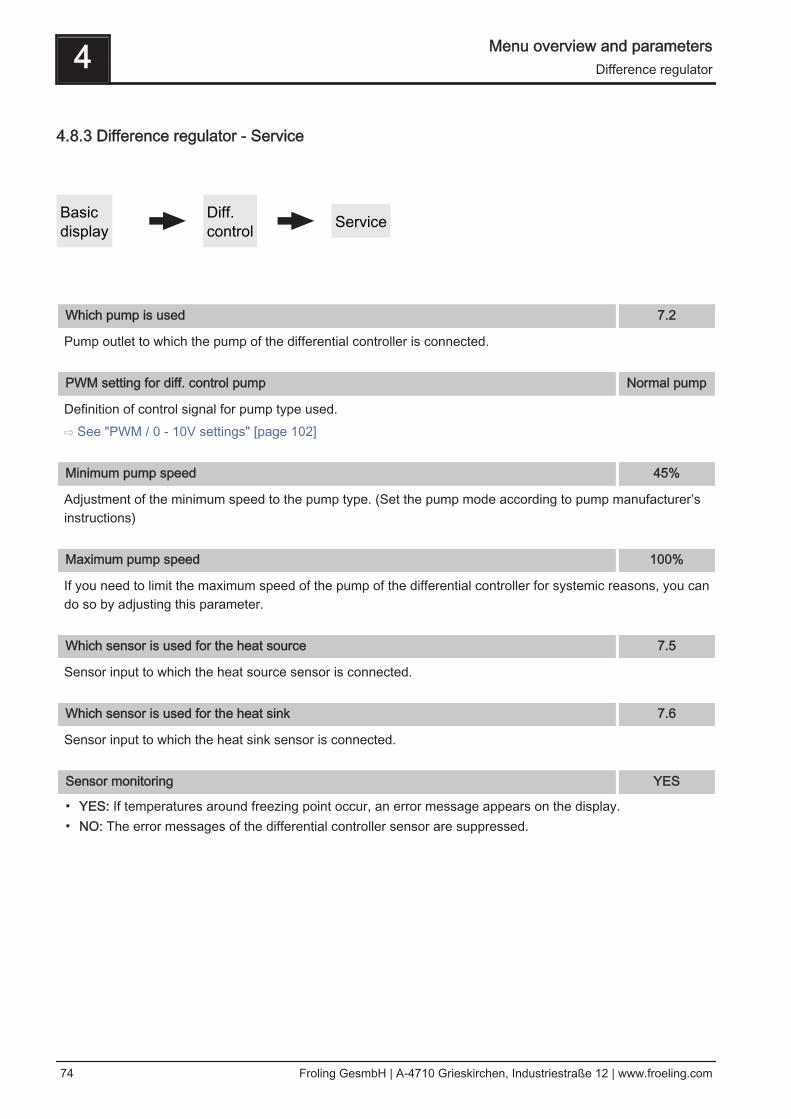
4.8.3 Difference regulator - Service
Basic display
Diff.control Service
Which pump is used 7.2
Pump outlet to which the pump of the differential controller is connected.
PWM setting for diff. control pump Normal pump
Definition of control signal for pump type used.⇨ See "PWM / 0 - 10V settings" [page 102]
Minimum pump speed 45%
Adjustment of the minimum speed to the pump type. (Set the pump mode according to pump manufacturer’sinstructions)
Maximum pump speed 100%
If you need to limit the maximum speed of the pump of the differential controller for systemic reasons, you cando so by adjusting this parameter.
Which sensor is used for the heat source 7.5
Sensor input to which the heat source sensor is connected.
Which sensor is used for the heat sink 7.6
Sensor input to which the heat sink sensor is connected.
Sensor monitoring YES
▪ YES: If temperatures around freezing point occur, an error message appears on the display.▪ NO: The error messages of the differential controller sensor are suppressed.
4 Menu overview and parametersDifference regulator
74 Froling GesmbH | A-4710 Grieskirchen, Industriestraße 12 | www.froeling.com

4.9 Circulation pump
4.9.1 Circulation pump - Status
Basic display
Circ.pump State
Return temperature in secondary circulation line 45°C
Display of the current temperature at the return feed sensor of the circulation line.NOTICE! If the parameter “Return sensor present” is set to “NO”, 0°C is permanently displayed.
Flow switch on the domestic hot water line 0
▪ 0: Flow switch detects no flow rate.▪ 1: Flow switch detects flow rate.
Speed of the circulation pump 100%
Specifies the current speed of the circulation pump.
Menu overview and parameters 4Circulation pump
Service Manual S-Tronic Plus / Lambda | B1010315_en 75

4.9.2 Circulation pump - Temperatures
Basic display
Circ.pump Temperatures
Return sensor present NO
▪ NO: The circulation pump is controlled according to time program. In conjunction with the use of a flowvalve, the circulation pump is also activated at a signal from the flow valve.
▪ YES: The circulation pump is controlled according to time program and temperature at the return circulationline. In conjunction with the use of a flow switch, the circulation pump is also activated at a signal from theflow switch.
NOTICE! Connect the flow sensor as the return sensor!
Switch off the pump at what return temperature in the circulation line 35°C
If the set temperature at the return circulation line is reached, the circulation pump will be deactivated.NOTICE! Parameter only relevant when using a return feed sensor in the circulation line!
Circulation pump run-on 300s
When the flow switch does not detect any more flow, the circulation pump remains active for the time set.NOTICE! Parameter only relevant when using a flow switch!
4 Menu overview and parametersCirculation pump
76 Froling GesmbH | A-4710 Grieskirchen, Industriestraße 12 | www.froeling.com

4.9.3 Circulation pump - Service
Basic display
Circ.pump Service
Which sensor is used for the circulation return 0.6
Sensor input to which the sensor at the return line of the circulation is connected.
Which sensor is used for the flow switch 1.5
Sensor input to which the flow switch is connected.
Which pump is used for the circulation 3.1
Pump outlet to which the circulation pump is connected.
PWM settings for the circulation pump Normal pump
Definition of control signal for pump type used.⇨ See "PWM / 0 - 10V settings" [page 102]
Minimum speed of the circulation pump 45%
Adjustment of the minimum speed to the pump type. (Set the pump mode according to pump manufacturer’sinstructions)NOTICE! Parameter not in use!
Maximum speed of the circulation pump 100%
If you need to limit the maximum speed of the circulation pump for systemic reasons, you can do so by adjust‐ing this parameter.
Menu overview and parameters 4Circulation pump
Service Manual S-Tronic Plus / Lambda | B1010315_en 77
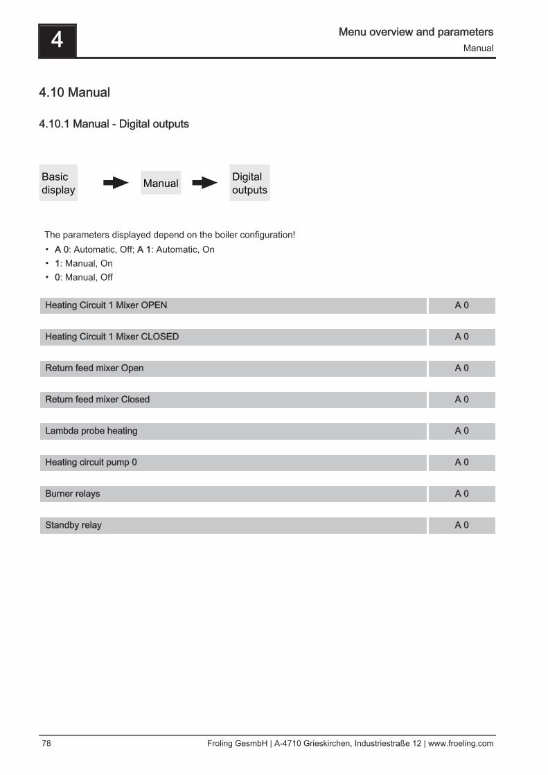
4.10 Manual
4.10.1 Manual - Digital outputs
Basic display Manual Digital
outputs
The parameters displayed depend on the boiler configuration!▪ A 0: Automatic, Off; A 1: Automatic, On▪ 1: Manual, On▪ 0: Manual, Off
Heating Circuit 1 Mixer OPEN A 0
Heating Circuit 1 Mixer CLOSED A 0
Return feed mixer Open A 0
Return feed mixer Closed A 0
Lambda probe heating A 0
Heating circuit pump 0 A 0
Burner relays A 0
Standby relay A 0
4 Menu overview and parametersManual
78 Froling GesmbH | A-4710 Grieskirchen, Industriestraße 12 | www.froeling.com

4.10.2 Manual - Analogue outputs
Basic display Manual Analogue
outputs
The parameters displayed depend on the boiler configuration!▪ A 0: Automatic, Off; A 1-100%: Automatic, with % value ON▪ 1-100%: Manual, with % value ON▪ 0%: Manual, Off
Primary air Actual value:20%
A 18%
Secondary air Actual value:5%
A 5%
ID Fan Actual value:0U
A 0%
Pump 1 on core module A 0%
Pump 0.1 A 0%
Pump 0.2 A 0%
Pump 1.1 A 0%
Pump 1.2 A 0%
Pump 2.1 A 0%
Pump 2.2 A 0%
Pump 3.1 A 0%
Pump 3.2 A 0%
Pump 4.1 A 0%
Menu overview and parameters 4Manual
Service Manual S-Tronic Plus / Lambda | B1010315_en 79

Pump 4.2 A 0%
Pump 5.1 A 0%
Pump 5.2 A 0%
Pump 6.1 A 0%
Pump 6.2 A 0%
Pump 7.1 A 0%
Pump 7.2 A 0%
4 Menu overview and parametersManual
80 Froling GesmbH | A-4710 Grieskirchen, Industriestraße 12 | www.froeling.com
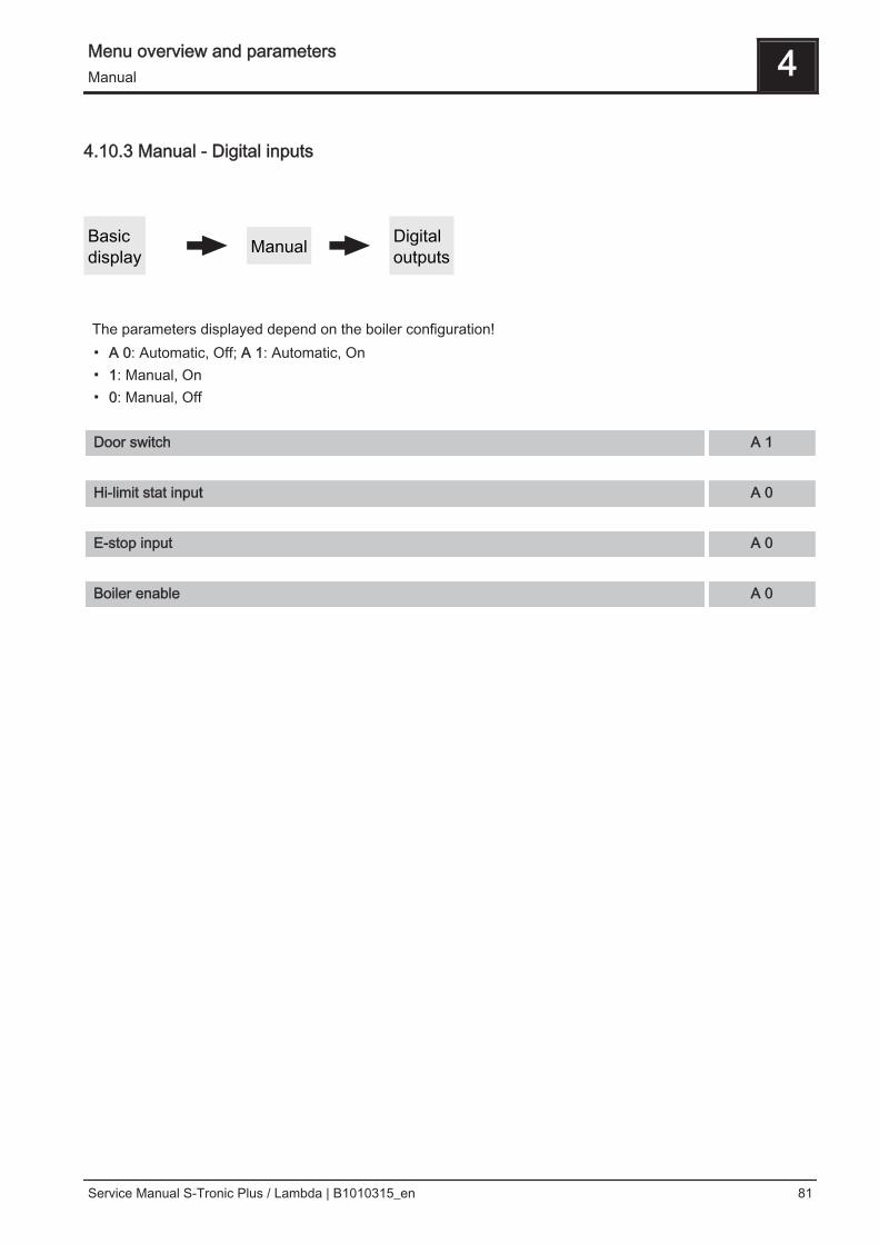
4.10.3 Manual - Digital inputs
Basic display Manual Digital
outputs
The parameters displayed depend on the boiler configuration!▪ A 0: Automatic, Off; A 1: Automatic, On▪ 1: Manual, On▪ 0: Manual, Off
Door switch A 1
Hi-limit stat input A 0
E-stop input A 0
Boiler enable A 0
Menu overview and parameters 4Manual
Service Manual S-Tronic Plus / Lambda | B1010315_en 81

4.11 System
4.11.1 System - Settings
Setting - Boiler temperature
Basic display System Setting Boiler temperature
Boiler temperature setpoint 80°C
The boiler temperature is regulated to this temperature. Setting range 60 – 90°C
Shutdown if current boiler temperature is higher than boiler setpoint + 5°C
If the boiler temperature setpoint is exceeded by this value, the boiler switches to “slumber” status. The boilerstarts up again below the boiler temperature setpoint.
Always shutdown when boiler maximum setpoint is exceeded by 3°C
If the maximum boiler temperature setpoint is exceeded by this value, the heating circuit pumps, the DHW tankloading pumps and the buffer tank pump are also activated for cooling the boiler, and the boiler switches to“slumber” status. If the current boiler temperature falls below the boiler temperature setpoint, the boiler startsup again.
Minimum boiler temperature to release all pumps -
When the current boiler temperature reaches this value, the buffer loading pump is started. (Hysteresis: 2°C)
Minimum return temperature 60°C
Prerequisite: Return temperature control with mixing valveThe minimum temperature value required of the return to the boiler.
4 Menu overview and parametersSystem
82 Froling GesmbH | A-4710 Grieskirchen, Industriestraße 12 | www.froeling.com

Setting - Flue gas
Basic display System Setting Flue gas
Maximum heating up time, during which HEATING status must be reached 10 min
If the criteria for the “Heating” status is not reached after a specified time, it switches to “Heating” status re‐gardless. When the flue gas temperatures rises and the residual oxygen content falls, the “Heating” status re‐mains active. If the criteria for “Heating” status is not reached within 5 mins, the boiler switches to “Off” status.
Minimum flue gas temperature -
Lowest operation point of flue gas temperature for continuous operation.
Max. flue gas temperature -
Highest operation point of flue gas temperature for continuous operation.
Start increase of flue gas temperature -
The flue gas setpoint rises by the specified value set here during “Heating up” status.
Minimum difference between flue gas temperature and boiler temperature in HEATING -
As a condition for the “Heating” operating status, the difference between the current flue gas temperature andthe current boiler temperature must at least exceed the value set here.
Flue gas temperature, below which boiler switches to OFF status -
If the flue gas temperature is below this value for the duration of the “Maximum heating up time, dur-ing which HEATING status must be reached”, the boiler switches to “Off” status.
Desired work point of flue gas temperature -
Menu overview and parameters 4System
Service Manual S-Tronic Plus / Lambda | B1010315_en 83

Setting - Air settings
Basic display System Setting Air settings
Minimum ID fan speed -
Lower operation point of the ID fan characteristic line.
ID fan min -
Base point for setting the ID fan characteristic line.
ID fan max -
End point for setting the ID fan characteristic curve.
Minimum primary air -
The opening of the primary air flap is not lower than the set value.
Minimum secondary air in heating -
In “Heating” status, the opening of the secondary air flap is not lower than the specified value.
Secondary air at door open during status Heating -
If the insulated door of the boiler is opened in “Heating” status, the secondary air flap is opened to the specifiedvalue.
Primary air during slumber -
In “Slumber” status, the primary air flap is opened to the specified value.
Safety time for checking for air leaks -
In “Heating” status, if the control of the secondary air flap is “0%” and the current flue gas temperature is over“100°C” the safety time starts. If, within this set period of time, the two values do not change, a warning ap‐pears on the display.
Primary air opening at 0% signal -
At 0% control of the primary air flap, this will open by the specified value.
Opening of primary air flap at 100% control -
At 100% control of the primary air flap, this will open by the maximum specified value.
4 Menu overview and parametersSystem
84 Froling GesmbH | A-4710 Grieskirchen, Industriestraße 12 | www.froeling.com

Secondary air opening at 0% signal -
At 0% control of the secondary air flap, this will open by the specified value.
Secondary air opening at 100% signal -
At 100% control of the secondary air flap, this will open by the maximum specified value.
Menu overview and parameters 4System
Service Manual S-Tronic Plus / Lambda | B1010315_en 85

Setting - Lambda values
Basic display System Setting Lambda values
Residual oxygen content setpoint -
Residual oxygen content which is regulated during “Heating” status.
Residual oxygen content, above which it switches to SHUTDOWN -
If the current residual oxygen content in “Heating” status exceeds the specified value for the duration of the“Maximum heating up time, during which HEATING status must be reached”, the boilerswitches to “Off” status.
Setting - Lambda values - LSM11 Lambda probe
Basic display System Setting Lambda values
LSM11Lambda probe
Residual oxygen content 21.0%
Displays the current residual oxygen content.
Lambda probe voltage measured -10.00 m
Display of the current measured Lambda probe voltage.
Lambda probes correction value 0.0
Lambda probe voltage corrected -10.00m
Display of the measured Lambda probe voltage, at which the “Lambda probe correction value” is tak‐en into account.
4 Menu overview and parametersSystem
86 Froling GesmbH | A-4710 Grieskirchen, Industriestraße 12 | www.froeling.com

Setting - Lambda values - Broadband probe
Basic display System Setting Lambda values
Broadband probe
Residual oxygen content 21.0%
Displays the current residual oxygen content.
Broadband probe type(1 .. Bosch / 2 .. NTK)(3 .. LSM11 input)
1
Setting the type of broadband probe used.
Lambda probe heating A 1
▪ A 0: Automatic, Off; A 1: Automatic, On▪ 1: Manual, On▪ 0: Manual, Off
Broadband probe calibration (probe must be at 21% O2) NO
▪ YES: After activation of the lambda probe heating, the broadband probe can be calibrated.NOTICE! The broadband probe must be at 21% oxygen (air)!
Broadband probe heating current 0.00A
Display of the measured broadband probe heating current.
Broadband probe heating voltage 0.00V
Display of the measured broadband probe heating voltage.
Broadband probe Nernst voltage 0.000V
Display of the measured broadband probe Nernst voltage.
Broadband probe pump current 0.000m
Display of the measured broadband probe pump current.
Broadband probe internal resistance 0 Ohm
Display of the measured broadband probe internal resistance.
Menu overview and parameters 4System
Service Manual S-Tronic Plus / Lambda | B1010315_en 87

Determining the probe type
The type of probe installed must be determined before starting calibration. To this end, coloured stickers(BOSCH = blue, NTK= yellow) are affixed to the connection cable of the probe, as well as to each end of theextension cable.
BOSCH broadband probe NTK broadband probe
Once the type of probe has been determined, the parameters need to be adjusted accordingly in the controller.
Starting calibration
❒ Set the type of probe used➥ BOSCH = 1, NTK = 2
For boilers with manual loading:❒ Open the insulated door
➥ Before starting calibration, the insulated door must be open for at least 3 - 4minutes so that the probe is warm enough and the boiler is sufficientlyventilated
For boilers with automatic loading:❒ Boiler must be switched off
➥ Status “Boiler OFF” or “Standby”❒ Set the “Lambda probe heating” parameter to “1”
➥ Heat broadband probe for at least 2 minutes Calibrate probe:NOTICE! The broadband probe must be at 21% oxygen (air)!
❒ Go to parameter “Broadband probe calibration”❒ Set parameter to “YES” and press the enter key
➥ Automatic calibration of the broadband probe begins➥ Once calibration is complete the parameter is automatically set to “NO” and the
broadband probe is ready for use
4 Menu overview and parametersSystem
88 Froling GesmbH | A-4710 Grieskirchen, Industriestraße 12 | www.froeling.com

Setting - General settings
Basic display System Setting General settings
Fuel selection Firewoodw<15%
▪ Firewood w<15%: If firewood is to be burnt with a water content (w) of less than 15%, then this setting mustbe selected. A prompt message then appears to confirm whether the specified values for the chosen fuelselection should be adopted.
▪ Firewood w>15%: If firewood is to be burnt with a water content (w) of more than 15%, then this settingmust be selected. A prompt message then appears to confirm whether the specified values for the chosenfuel selection should be adopted.
Modem installed NO
▪ NO: The boiler does not have a modem for data transfer installed.▪ YES: The boiler has a modem for data transfer installed.
Memory cycle of data logger 5s
If the boiler is equipped with a data logger the most important boiler data is stored on a SD card. This parame‐ter specifies at what intervals the recording should be started.
Send a line break when ASCII data output on COM2 NO
▪ NO: When a new data set is issued it will be added to the previous one.▪ YES: A line break for better visualisation is sent between the individual data sets.
Reset counter since last maintenance NO
▪ NO: The service hours counter since last maintenance continues to run.▪ YES: The service hours counter since last maintenance is set to “0”.
Adopt specified material values NO
▪ YES: The preset boiler parameters for the chosen fuel selection are adopted. When the process iscompleted the parameter changes back to “NO”.
Adopt specified boiler values NO
▪ YES: The preset boiler parameters for the selected boiler type are adopted. When the process is completedthe parameter changes back to “NO”.
Adopt standard settings (all values are reset) NO
▪ YES: Adopting standard factory settings This resets all parameters! Once the settings have been applied,the parameter automatically switches to “NO” and the boiler must be reset; otherwise, boiler functioning isno longer guaranteed.
Menu overview and parameters 4System
Service Manual S-Tronic Plus / Lambda | B1010315_en 89

EEPROM reset NO
▪ YES: All boiler settings and system configurations are deleted. The boiler is only functional again once it hasbeen recommissioned by Fröling customer services or authorized installer.
4 Menu overview and parametersSystem
90 Froling GesmbH | A-4710 Grieskirchen, Industriestraße 12 | www.froeling.com

4.11.2 System - Current values
Basic display System Current values
Display of the current value for the relevant parameter. The parameters displayed depend on the boiler config‐uration!
Boiler temperature 25°C
Flue gas temperature 28°C
Flue gas setpoint 38°C
Boiler control variable 100%
ID fan control 0%
ID fan speed 0 rpm
Primary air 0%
Position of primary air flap 0%
Residual oxygen content 1.9%
Oxygen control 100%
Secondary air 0%
Position of secondary air flap 0%
Outside air temperature 2°C
Board temperature 26°C
Return sensor 23°C
Service hours 15h
Menu overview and parameters 4System
Service Manual S-Tronic Plus / Lambda | B1010315_en 91

Service hours in slumber 0h
Operation hours for cascade mode 15h
Operation hours ignition 1h
Hours since last maintenance 15h
Software version Version 50.04Build 05.11
Air speed:Sensor offset:Raw value:Air in SB:
4.54m/s3116
00.00m/s
O2 measured:O2 calculated:
1.9%9.0%
Curr. pos.: 0Open: 0 Close: 0Path: 0 Retry: 0State: TEST
Closed
Cust. no.:Boiler no.:EQU no.:
2635850560
1999999999
Hours of boiler 2 (burner relays) 1h
4 Menu overview and parametersSystem
92 Froling GesmbH | A-4710 Grieskirchen, Industriestraße 12 | www.froeling.com

4.11.3 System - Error
Error - Error display
Basic display System Error Error display
Display of the current fault messages. In addition, you can also invoke time information here, such as when thefault occurred, when the fault was acknowledged and when the fault was cleared.
Error - Clear pending error
Basic display System Error Clear pending error
Depending on the system configuration, the status LED can flash red even though no fault messages arepending. Pending fault messages which are not visible can also be resolved using this function.
Error - Error history
Basic display System Error Error buffer
Up to 50 fault indication entries are stored in the error history. A fault can consist of up to 3 fault indicationentries. You can determine what type of fault message it is, when the fault occurred (appeared), when the faultwas acknowledged and when the fault was eliminated (cleared). If all 50 fault indication entries are in use andthere is another fault indication entry, the oldest entry will be deleted to make room for the current one.
Error - Clear error history
Basic display System Error Clear error history
The entire error history can be deleted using this function. From this point onwards the error history is popula‐ted with fault indication entries which have occurred since clearing the error history.
Menu overview and parameters 4System
Service Manual S-Tronic Plus / Lambda | B1010315_en 93

4.11.4 System - Sensors and pumps
Basic display System Sensors and
pumps
In the “Sensors and pumps” menu, all sensor inputs and pump outputs available in the hydraulic system canbe allocated. The number of parameters depends on the configuration.
Which sensor is used for buffer tank top -
Which sensor is used for bottom buffer tank -
Which pump is used for the buffer tank -
: -
4 Menu overview and parametersSystem
94 Froling GesmbH | A-4710 Grieskirchen, Industriestraße 12 | www.froeling.com

4.11.5 System - Display operating rights
Basic display System Display
operating rights
In this menu the operating rights for the individual room consoles are allocated. If access from a room consoleto a heating system component is permitted, then the corresponding parameter must be set to “YES”. Thenumber of menus as well as the parameter entries depend on the system configuration!NOTICE! The operating rights of the room consoles should be allocated from the boiler console, as unrestric‐ted access is only possible here.
“Touch display with address 1 – 7” and “Button display with address 1 – 7”
Heating system:
Allow access to heating circuit 01? NO
Allow access to heating circuit 02? NO
: :
Allow access to heating circuit 18? NO
DHW tank system:
Allow access to DHW tank 01? NO
Allow access to DHW tank 02? NO
: :
Allow access to DHW tank 08? NO
Buffer tank system:
Allow access to buffer tank 01? NO
: :
Allow access to buffer tank 04? NO
Solar panel system:
Allow access to solar 01? NO
Menu overview and parameters 4System
Service Manual S-Tronic Plus / Lambda | B1010315_en 95

Heating system:
Additional freely programmable differential controller installed NO
Network pump installed NO
Circulation pump installed NO
Is any secondary boiler installed? (oil, gas, wood...) NO
Feeder pump House 1 installed NO
: :
Feeder pump House 4 installed NO
In the cascade, this boiler is the MASTER NO
4 Menu overview and parametersSystem
96 Froling GesmbH | A-4710 Grieskirchen, Industriestraße 12 | www.froeling.com

4.11.6 System - Display allocations
Basic display System Display
allocations
Room temperature sensor correction:If a deviation of the room temperature is determined from the evaluated value to the displayed value, the eval‐uation of the room temperature sensor can be adjusted with the following parameters.
Deviation of room sensor from Touch display with address 1 0°C
: :
Deviation of room sensor from touch display with address 7 0°C
Deviation of room sensor from button display with address 1 0°C
: :
Deviation of room sensor from button display with address 7 0°C
Heating system:To assign a room console to a heating circuit, the respective heating circuit number with its address must seton the room console. The parameters are set to “none” at the factory!
Touch display with address 1 is allocated to the following heating circuit: None
: :
Touch display with address 7 is allocated to the following heating circuit: None
Button display with address 1 is allocated to the following heating circuit: None
: :
Button display with address 7 is allocated to the following heating circuit: None
Menu overview and parameters 4System
Service Manual S-Tronic Plus / Lambda | B1010315_en 97

DHW tank system:To assign a room console to a DHW tank, the respective DHW tank number with its address must set on theroom console. The parameters are set to “none” at the factory!
Touch display with address 1 is allocated to the following DHW tank: None
: :
Touch display with address 7 is allocated to the following DHW tank: None
Button display with address 1 is allocated to the following DHW tank: None
: :
Button display with address 7 is allocated to the following DHW tank: None
4 Menu overview and parametersSystem
98 Froling GesmbH | A-4710 Grieskirchen, Industriestraße 12 | www.froeling.com

4.11.7 System - Basic display parameters
Basic display System Basic display
parameters
You can individually adjust how the two items are shown in the basic display, and for each item you canchoose from several parameters: e.g. boiler, flue gas, external, room, DHW tank, buffer tank top, buffer tankbottom, buffer tank graph, ...
Position 1 Boiler Selected
Position 2 Flue gas Selected
If the “buffer tank graph” is selected, the temperatures of the top, middle (if available) and bottom buffer tankwill be displayed next to the graph. In addition, further, fixed predefined values will be displayed:OT ... Outside temperatureBT ... Boiler temperatureRT ... Room temperature (on room console BT is replaced by RT)DT ... DHW tank temperature (if available)
Menu overview and parameters 4System
Service Manual S-Tronic Plus / Lambda | B1010315_en 99

4.11.8 System - Language
Basic display System Language
Language - Sprache - Langue - Lingua - Jezik Deutsch
The following languages can be set:▪ Deutsch, English, Francais, Italiano, Slovenski, Cesky, Polski, Svenska, Espanol, Magyar, Suomi, Dansk,
Nederlands
4.11.9 System - Current Date
Basic display System Current Date
Current Date TH 08/01/2015
Display and setting of current date.
4.11.10 System - Current Time
Basic display System Current Time
Current Time 14:40:15
Display and setting the current time.
4 Menu overview and parametersSystem
100 Froling GesmbH | A-4710 Grieskirchen, Industriestraße 12 | www.froeling.com

4.11.11 System - Current User Level
Basic display System Current User Level
Operating level Description
Child lock(Code “0”)
At “Child lock” level, only the “Status” menu appears. It is not possible tochange parameters at this level.
Customer(Code “1”)
Standard level for normal operation of the display. All customer-specificparameters are displayed and can be changed.
Installer / Service Releases parameters to adjust the controller to the system components (ifconfigured).
4.11.12 System - System selection
Basic display System System selection
⇨ See "Setting the system type" [page 25]
Menu overview and parameters 4System
Service Manual S-Tronic Plus / Lambda | B1010315_en 101

5 FAQ
5.1 PWM / 0 - 10V settings
Description
▪ Normal pump (pump with load-tap changer)Set when a standard pump a switching valve with RC element is run at the respective output. When usinga switching valve, set the minimum speed of the output to 100%. When a pump is used, it is controlled atthe 230V output using pulse packets.
▪ PDM / field pumpThere is a permanent power supply of 230V at the output for the high efficiency pump. The pump iscontrolled using pulse duration modulation at the respective PWM output.
▪ PWM / Solar pumpHere again, the pump is controlled by means of pulse duration modulation at the respective PWM output.In this case, however, the characteristic line is inverted and can only be used for specially marked highefficiency solar pumps.
▪ PWM field pump+valveThe signal for the field pump is emitted at the PWM output. If the signal exceeds 2%, the 230V output isswitched on. If the signal is below 2% for more than 4 minutes, the output is switched off again.
▪ PWM sol.pump+valveThe signal for specially marked high efficiency solar pumps is emitted at the PWM output. If the signalexceeds 2%, the 230V output is switched on. If the signal is below 2% for more than 4 minutes, the outputis switched off again.
▪ 0 – 10V / field pump▪ 0 – 10V / solar pump▪ 0 – 10V field pump+valve▪ 0 – 10V solar pump+valve
The same functions that apply with PWM apply to the parameter values with 0-10V. The only difference isthat instead of pulse duration modulation, a 0-10V signal is used to control the pump.
5 FAQPWM / 0 - 10V settings
102 Froling GesmbH | A-4710 Grieskirchen, Industriestraße 12 | www.froeling.com

6 Menu structure - S-Tronic Plus / Lambda
Service Manual S-Tronic Plus / Lambda | B1010315_en 103