rvs-dx - solconllc.comsolconllc.com/assets/pdf/rvs_dndx/rvsdx-instruction-manual.pdf · during...
TRANSCRIPT

RRVVSS--DDXXDDiiggiittaall SSoofftt SSttaarrtteerr wwiitthh iinntteerrnnaall BByyPPaassss88--11110000AA,, 222200--669900VV
IInnssttrruuccttiioonn MMaannuuaall1BVer. 26/12/2012
2 • Table of content
__________________________________________________________________________________
RVS-DX Instruction Manual 1. TABLE OF CONTENT 1. Table of content ........................................................................................................................ 2
2. Safety & Warnings .................................................................................................................... 4
2.1 Safety .......................................................................................................................................... 4 2.2 Attention ...................................................................................................................................... 4 2.3 Warnings ..................................................................................................................................... 4
3. Technical Data .......................................................................................................................... 5
3.1 Introduction ................................................................................................................................. 5 3.2 Rating and frames sizes ............................................................................................................. 5 3.3 Starter Selection ......................................................................................................................... 5
3.3.1 Motor current & Starting Conditions ................................................................................ 5 3.3.2 Mains Voltage (line to line) .............................................................................................. 6 3.3.3 Control Voltage ............................................................................................................... 6 3.3.4 Other Options .................................................................................................................. 6 3.3.5 Starter selection tables for various voltage ratings. ........................................................ 6
3.3.5.1 Starter selection for 230V, 400V, 480V, 600V ......................................................... 6 3.3.6 Ordering Information ....................................................................................................... 7
4. Recommended Wiring Scheme ............................................................................................... 8
4.1 Typical wiring diagram ................................................................................................................ 8 4.2 Power wiring scheme for “Inside-Delta” Connection .................................................................. 9 4.3 Wiring Notes ............................................................................................................................... 9
4.3.1 Short Circuit Protection ................................................................................................. 10 4.3.2 Transient Protection ...................................................................................................... 10 4.3.3 Control Supply (Terminals A1, A2) ................................................................................ 10 4.3.4 Start/Stop (or 4.3.4momentary start) Input (terminal B1) .............................................. 10 4.3.5 Aux. Input (terminal C1) ................................................................................................ 11 4.3.6 Auxiliary output relay (terminals 13, 14) ........................................................................ 11 4.3.7 Fault Contact (terminals 23, 24) .................................................................................... 11 4.3.8 Options description ....................................................................................................... 11
4.3.8.1 Analogue I/O (option # 5) (terminals T1, T2, Gnd, Out (-), Out (+)) ...................... 11 4.3.8.2 RS-485 Communication (option # 3M) (terminals out(-),Out(+)) ........................... 12
4.3.9 “Inside-Delta” mode ....................................................................................................... 12 4.3.9.1 General information ................................................................................................ 12 4.3.9.2 Notes on “Inside Delta” connection ........................................................................ 13
5. Dimensions ............................................................................................................................. 14
6. Installation ............................................................................................................................... 18
6.1 Prior to Installation .................................................................................................................... 18 6.2 Mounting ................................................................................................................................... 18 6.3 Temperature range & heat dissipation ...................................................................................... 18
6.3.1 Calculating the enclosure size, for non-ventilated metallic enclosure ........................... 18 6.3.2 Additional Ventilation ..................................................................................................... 19 6.3.3 UL, cUL Installation Instructions .................................................................................... 19
7. Control Keypad ....................................................................................................................... 20
7.1 LCD Arrangement ..................................................................................................................... 20 7.2 Push-buttons ............................................................................................................................. 20 7.3 Status LEDs. ............................................................................................................................. 21 7.4 Reviewing and Modifying Parameters ...................................................................................... 21 7.5 Special Actions Performed in TEST/MAINTENANCE Mode .................................................... 21
7.5.1 Run Self Test ................................................................................................................ 21 7.5.2 View Software Version .................................................................................................. 21
3 • Table of content
__________________________________________________________________________________________
2551B7.5.3 Obtain Default Parameters ............................................................................................ 22 2552B7.5.4 Reset Statistical Data .................................................................................................... 22 2553B7.5.5 Calibrate Voltage, Current and (Factory Use Only!) ................................................... 23
2524B7.6 Mode Pages .............................................................................................................................. 23 2554B7.6.1 Overview of All Mode Pages and Factory Defaults ....................................................... 24 2555B7.6.2 Display Mode – page 0 ................................................................................................. 26 2556B7.6.3 Main Parameters – page 1 ............................................................................................ 27
2582B7.6.3.1 Tripping Curves of the Integrated Overload Protection .......................................... 30 2557B7.6.4 Start Parameters – page 2 ............................................................................................ 31
2583B7.6.4.1 Soft start parameters .............................................................................................. 34 2558B7.6.5 Stop Parameters – page 3 ............................................................................................ 35
2584B7.6.5.1 Soft stop parameters .............................................................................................. 35 2559B7.6.6 Dual Adjustment Parameters – page 4 ......................................................................... 37 2560B7.6.7 Special features Parameters – page 5 .......................................................................... 38
2585B7.6.7.1 WIDER SETTINGS Parameters: ............................................................................ 39 2561B7.6.8 Fault Parameters – page 6 ............................................................................................ 40 2562B7.6.9 I/O Programming Parameters – page 7 ........................................................................ 42
2586B7.6.9.1 PROG. INPUT C1 .................................................................................................. 43 2563B7.6.10 Comm. Parameters – page 8- Applicable with Optional Modbus & DeviceNet Comm. 44 2564B7.6.11 Comm. Parameters – page 8 - Applicable with Optional Profibus Comm. .................... 45 2565B7.6.12 Statistical Data – page 9 ............................................................................................... 46
2525B7.7 Non adjustable protection anf fault Resetting ........................................................................... 46 2566B7.7.1 Phase loss (and Under / Over Frequency) .................................................................... 46 2567B7.7.2 Phase Sequence ........................................................................................................... 47 2568B7.7.3 Shorted SCR or Wrong Connections ............................................................................ 47 2569B7.7.4 Heat-sink Over Temperature ......................................................................................... 47 2570B7.7.5 External Fault ................................................................................................................ 47 2571B7.7.6 Fault and Reset ............................................................................................................. 47 2572B7.7.7 Auto Reset .................................................................................................................... 47
2526B7.8 Timing Occurrence Table ......................................................................................................... 48
2504B8. STARTING PROCEDURE ....................................................................................................... 49
2527B8.1 Setting control voltage on-site RVS-DX8A-310A ...................................................................... 49 2528B8.2 Standard starting procedure ..................................................................................................... 50 2529B8.3 Examples of starting curves ...................................................................................................... 51
2573B8.3.1 Light Loads-Pumps, Fans, etc. ..................................................................................... 51 2574B8.3.2 High Inertia Loads – Fans, Centrifuges, etc .................................................................. 51 2575B8.3.3 Special starting – Using Dual Adjustment ..................................................................... 52
2587B8.3.3.1 Special starting – Using Dual Adjustment – wiring scheme ................................... 53 2576B8.3.4 Choosing a suitable Pump Curve (centrifugal Pumps) ................................................. 53
2588B8.3.4.1 Starting Curve ........................................................................................................ 53 2589B8.3.4.2 Stopping Curve ...................................................................................................... 54 2590B8.3.4.3 Final torque during soft-stopping a pump motor .................................................... 54
2505B9. TROUBLE SHOOTING ............................................................................................................ 55
2530B9.1 Blank RMA Form ...................................................................................................................... 58
2506B10. TECHNICAL SPECIFICATIONS: ............................................................................................ 59
4 • Safe ty & Warnings
__________________________________________________________________________________
2. SAFETY & WARNINGS
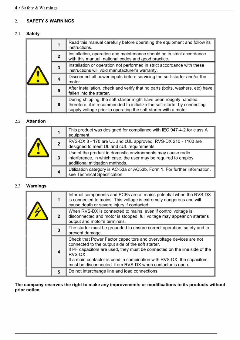
2.1 Safety
1 Read this manual carefully before operating the equipment and follow its instructions.
2 Installation, operation and maintenance should be in strict accordance with this manual, national codes and good practice.
3 Installation or operation not performed in strict accordance with these instructions will void manufacturer’s warranty.
4 Disconnect all power inputs before servicing the soft-starter and/or the motor.
5 After installation, check and verify that no parts (bolts, washers, etc) have fallen into the starter.
6During shipping, the soft-starter might have been roughly handled, therefore, it is recommended to initialize the soft-starter by connecting supply voltage prior to operating the soft-starter with a motor
2.2 Attention
1 This product was designed for compliance with IEC 947-4-2 for class A equipment.
2 RVS-DX 8 - 170 are UL and cUL approved. RVS-DX 210 - 1100 are designed to meet UL and cUL requirements.
3Use of the product in domestic environments may cause radio interference, in which case, the user may be required to employ additional mitigation methods.
4 Utilization category is AC-53a or AC53b, Form 1. For further information, see Technical Specification
2.3 Warnings
1Internal components and PCBs are at mains potential when the RVS-DX is connected to mains. This voltage is extremely dangerous and will cause death or severe injury if contacted.
2When RVS-DX is connected to mains, even if control voltage is disconnected and motor is stopped, full voltage may appear on starter’s output and motor’s terminals.
3 The starter must be grounded to ensure correct operation, safety and to prevent damage.
4
Check that Power Factor capacitors and overvoltage devices are not connected to the output side of the soft starter.If PF capacitors are used, they must be connected on the line side of the RVS-DX .If a main contactor is used in combination with RVS-DX, the capacitors must be disconnected from RVS-DX when contactor is open.
5 Do not interchange line and load connections
The company reserves the right to make any improvements or modifications to its products without prior notice.

5 • Technica l Data
___________________________________________________________________________________________
3. TECHNICAL DATA 3.1 Introduction The RVS-DX is a third generation, highly sophisticated and reliable starter designed for use with standard three-phase, three-wire, squirrel cage, induction motors. It provides the best method of reducing current and torque during motor starting. The RVS-DX starts the motor by supplying a slowly increasing voltage, providing soft start and smooth acceleration, while drawing the minimum current necessary to start the motor. The RVS-DX is equipped with internal by-pass controlled by its micro-controller. The by-pass closes after the end of the starting process, thus reducing heating and saving power. 3.2 Rating and frames sizes
Starter type Starter FLC [A]
Frame Size
Dimensions WxHxD [mm]
Weight [Kg]
RVS-DX 8 8 D1 120x232x122 3.0 RVS-DX 17 17 D1 120x232x122 3.0 RVS-DX 31 31 D1 120x232x122 3.0 RVS-DX 44 44 D1 120x232x122 3.0 RVS-DX 58 58 D2 129x275x182 5.2 RVS-DX 72 72 D2 129x275x182 5.2 RVS-DX 85 85 D3 129x380x182 8.5
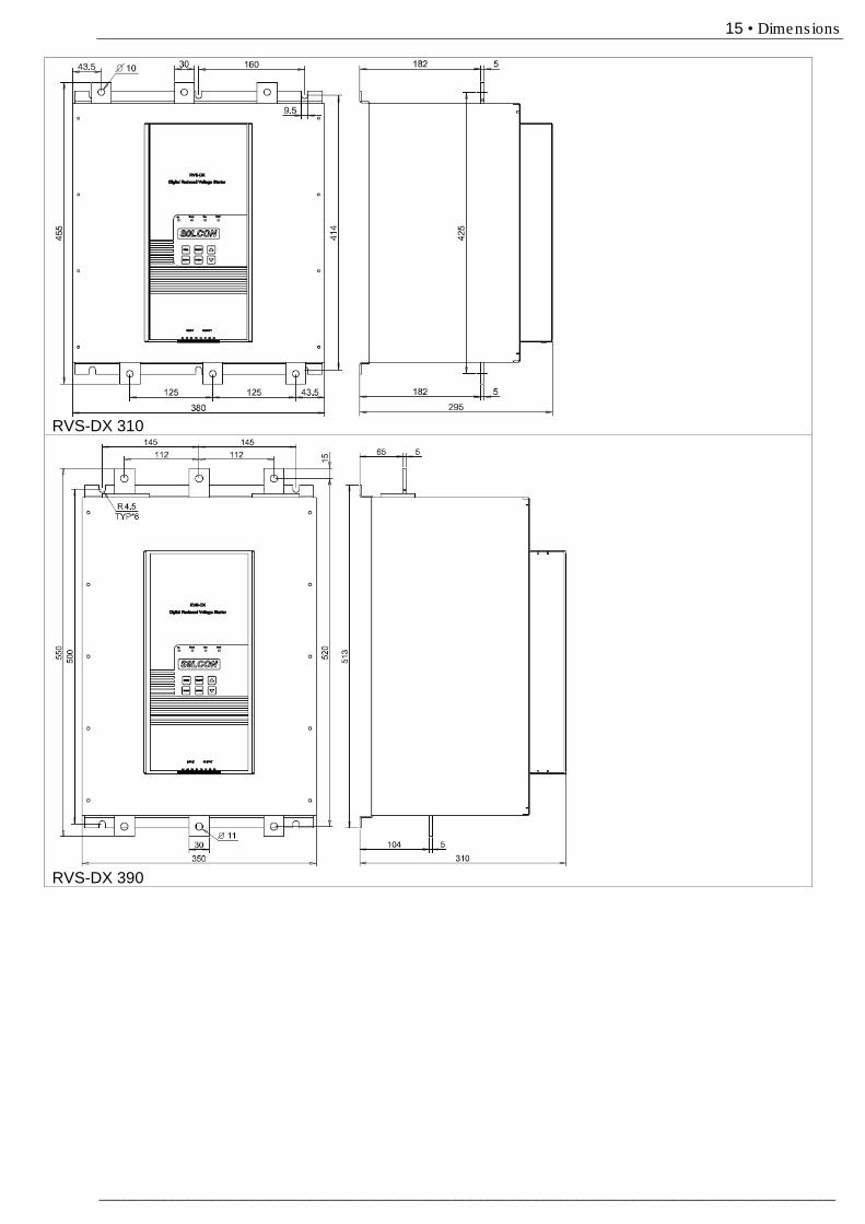
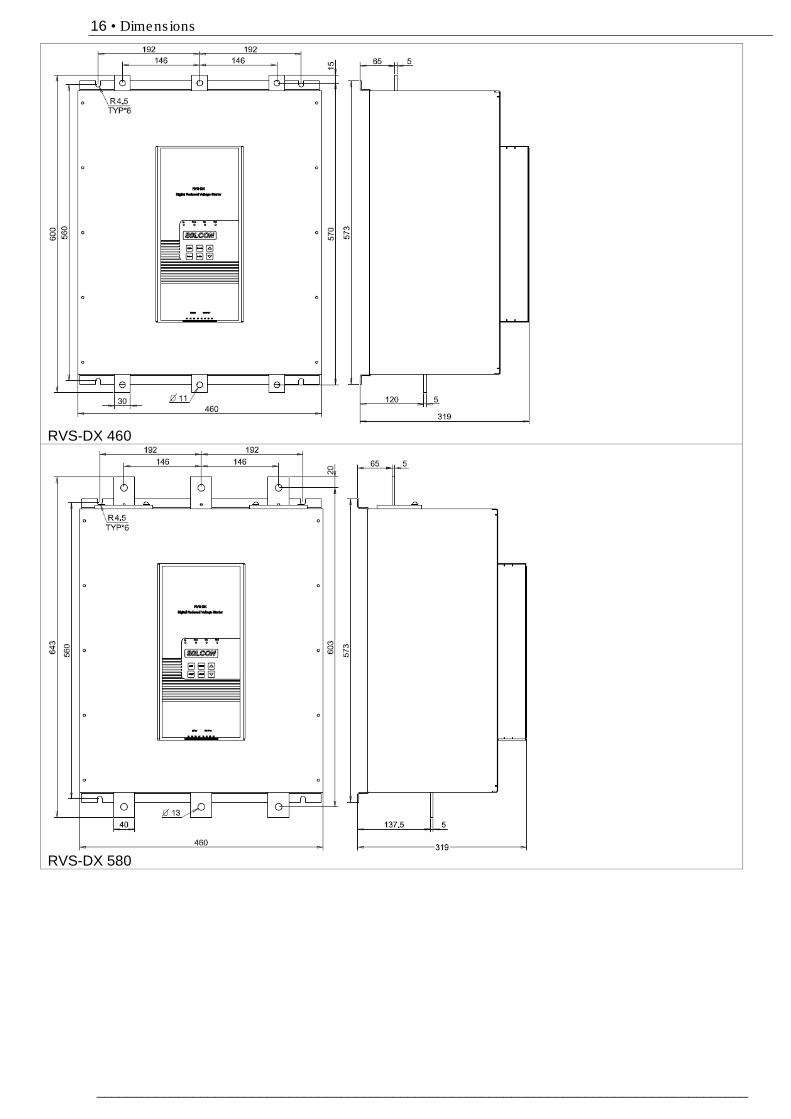
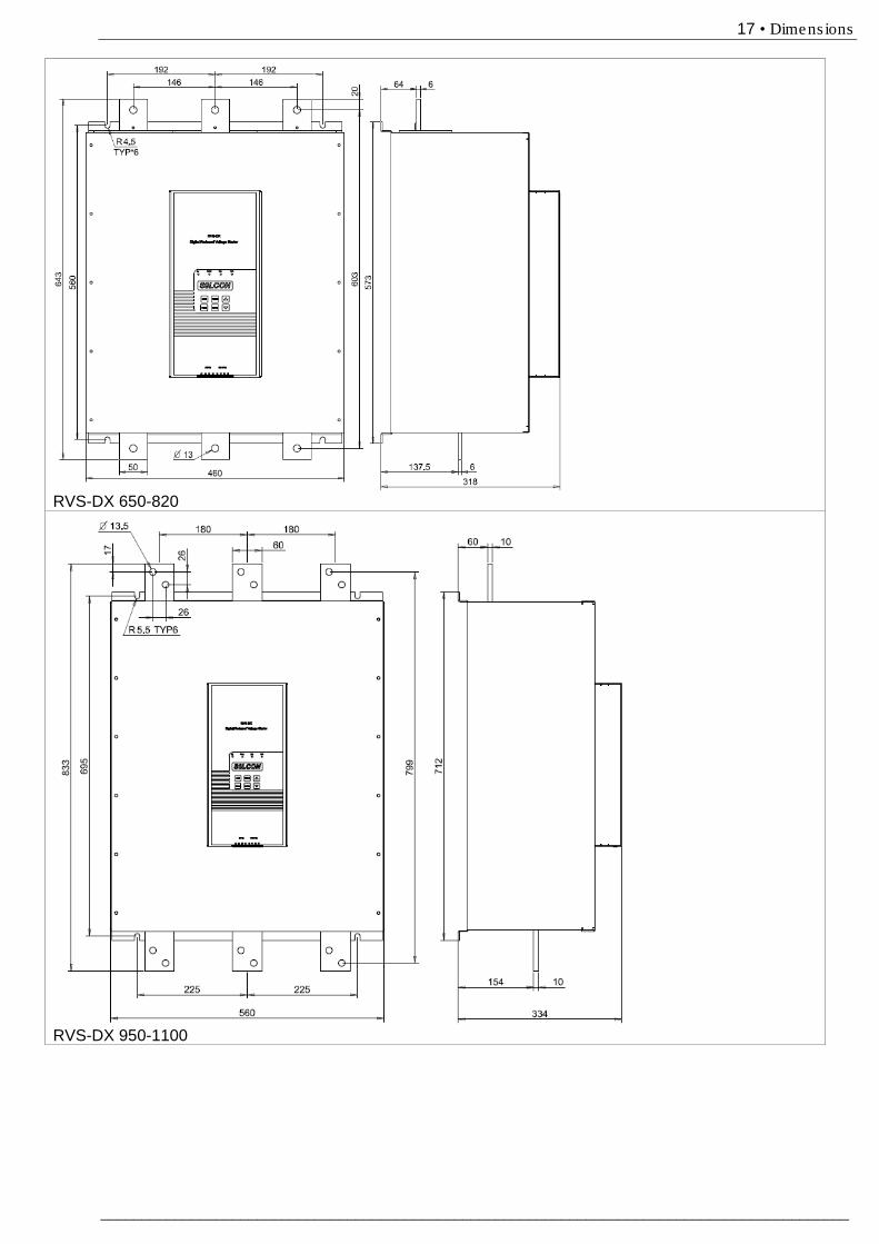
RVS-DX 105 105 D3 129x380x182 8.5 RVS-DX 145 145 D4 172x380x192 12.5 RVS-DX 170 170 D4 172x380x192 12.5 RVS-DX 210 210 D5 380x455x295 30.2 RVS-DX 310 310 D5 380x455x295 30.2 RVS-DX 390 390 D6 350x550x310 55 RVS-DX 460 460 D7 460x600x319 65 RVS-DX 580 580 D8 460x643x319 75 RVS-DX 650 650 D8 460x643x318 80 RVS-DX 820 820 D8 460x643x318 90 RVS-DX 950 950 D9 560x833x334 100
RVS-DX 1100 1100 D9 560x833x334 100
3.3 Starter Selection The starter should be selected in accordance with the following criteria: 3.3.1 Motor current & Starting Conditions Select the starter according to motor's Full Load Ampere (FLA) - as indicated on its nameplate (even if the motor will not be fully loaded). The RVS-DX is designed to operate under the following maximum conditions:
Ambient Temperature
[0C]
Starting Current [A]
Acceleration Time [sec]
40 300%xIn 30 350%xIn 20 400%xIn 5
Max. Starts per Hour: four (4) starts per hour at maximum ratings and up to 10 starts per hour at light load applications (consult factory). Note: For very frequent starts (inching applications) the inching current should be considered as the Full Load Current (FLC) (consult factory).
Notes: Refer to section 5 on page 14 for detailed dimensions.
6 • Technica l Data
________________________________________________________________________________________
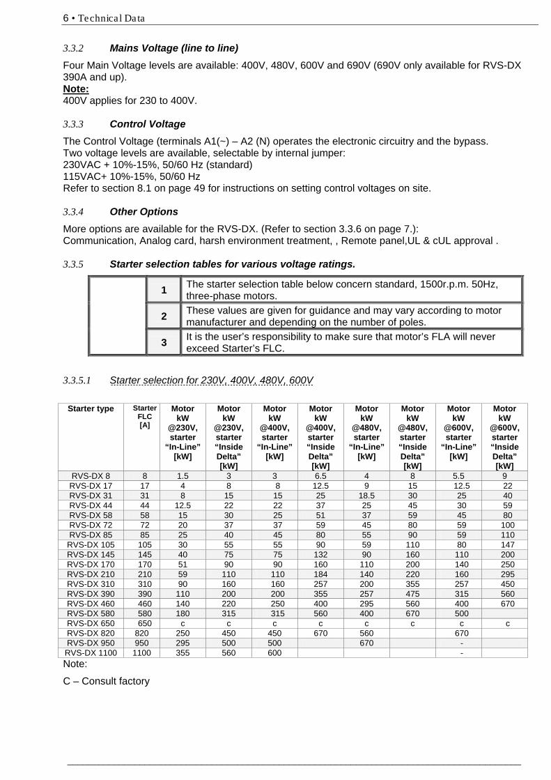
3.3.2 Mains Voltage (line to line) Four Main Voltage levels are available: 400V, 480V, 600V and 690V (690V only available for RVS-DX 390A and up). Note: 400V applies for 230 to 400V. 3.3.3 Control Voltage The Control Voltage (terminals A1(~) – A2 (N) operates the electronic circuitry and the bypass. Two voltage levels are available, selectable by internal jumper: 230VAC + 10%-15%, 50/60 Hz (standard) 115VAC+ 10%-15%, 50/60 Hz Refer to section 8.1 on page 49 for instructions on setting control voltages on site. 3.3.4 Other Options More options are available for the RVS-DX. (Refer to section 3.3.6 on page 7.): Communication, Analog card, harsh environment treatment, , Remote panel,UL & cUL approval . 3.3.5 Starter selection tables for various voltage ratings.
1 The starter selection table below concern standard, 1500r.p.m. 50Hz, three-phase motors.
2 These values are given for guidance and may vary according to motor manufacturer and depending on the number of poles.
3 It is the user’s responsibility to make sure that motor’s FLA will never exceed Starter’s FLC.
3.3.5.1 Starter selection for 230V, 400V, 480V, 600V
Note:
C – Consult factory
Starter type Starter FLC [A]
Motor kW
@230V, starter
“In-Line” [kW]
Motor kW
@230V, starter “Inside Delta” [kW]
Motor kW
@400V, starter
“In-Line” [kW]
Motor kW
@400V, starter “Inside Delta” [kW]
Motor kW
@480V, starter
“In-Line” [kW]
Motor kW
@480V, starter “Inside Delta” [kW]
Motor kW
@600V, starter
“In-Line” [kW]
Motor kW
@600V, starter “Inside Delta” [kW]
RVS-DX 8 8 1.5 3 3 6.5 4 8 5.5 9 RVS-DX 17 17 4 8 8 12.5 9 15 12.5 22 RVS-DX 31 31 8 15 15 25 18.5 30 25 40 RVS-DX 44 44 12.5 22 22 37 25 45 30 59 RVS-DX 58 58 15 30 25 51 37 59 45 80 RVS-DX 72 72 20 37 37 59 45 80 59 100 RVS-DX 85 85 25 40 45 80 55 90 59 110
RVS-DX 105 105 30 55 55 90 59 110 80 147 RVS-DX 145 145 40 75 75 132 90 160 110 200 RVS-DX 170 170 51 90 90 160 110 200 140 250 RVS-DX 210 210 59 110 110 184 140 220 160 295 RVS-DX 310 310 90 160 160 257 200 355 257 450 RVS-DX 390 390 110 200 200 355 257 475 315 560 RVS-DX 460 460 140 220 250 400 295 560 400 670 RVS-DX 580 580 180 315 315 560 400 670 500 RVS-DX 650 650 c c c c c c c c RVS-DX 820 820 250 450 450 670 560 670 RVS-DX 950 950 295 500 500 670 - RVS-DX 1100 1100 355 560 600 -
7 • Technica l Data
___________________________________________________________________________________________
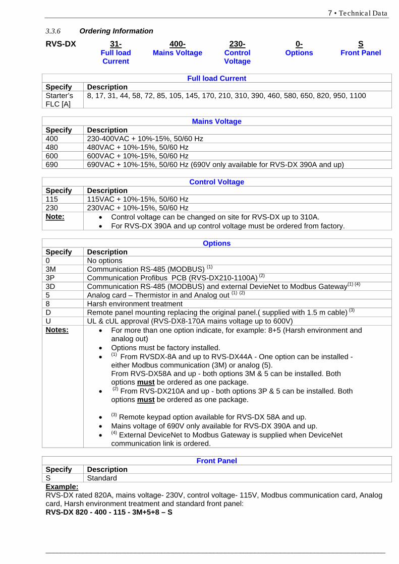
3.3.6 Ordering Information
RVS-DX 31- 400- 230- 0- S Full load
Current Mains Voltage Control
Voltage Options Front Panel
Full load Current
Specify Description Starter’s FLC [A]
8, 17, 31, 44, 58, 72, 85, 105, 145, 170, 210, 310, 390, 460, 580, 650, 820, 950, 1100
Mains Voltage
Specify Description 400 230-400VAC + 10%-15%, 50/60 Hz 480 480VAC + 10%-15%, 50/60 Hz 600 600VAC + 10%-15%, 50/60 Hz 690 690VAC + 10%-15%, 50/60 Hz (690V only available for RVS-DX 390A and up)
Control Voltage Specify Description 115 115VAC + 10%-15%, 50/60 Hz 230 230VAC + 10%-15%, 50/60 Hz Note: • Control voltage can be changed on site for RVS-DX up to 310A.
• For RVS-DX 390A and up control voltage must be ordered from factory.
Options Specify Description 0 No options 3M Communication RS-485 (MODBUS) (1) 3P Communication Profibus PCB (RVS-DX210-1100A) (2) 3D Communication RS-485 (MODBUS) and external DevieNet to Modbus Gateway(1) (4) 5 Analog card – Thermistor in and Analog out (1) (2) 8 Harsh environment treatment D Remote panel mounting replacing the original panel.( supplied with 1.5 m cable) (3) U UL & cUL approval (RVS-DX8-170A mains voltage up to 600V) Notes: • For more than one option indicate, for example: 8+5 (Harsh environment and
analog out) • Options must be factory installed. • (1) From RVSDX-8A and up to RVS-DX44A - One option can be installed -
either Modbus communication (3M) or analog (5). From RVS-DX58A and up - both options 3M & 5 can be installed. Both options must be ordered as one package.
• (2) From RVS-DX210A and up - both options 3P & 5 can be installed. Both options must be ordered as one package.
• (3) Remote keypad option available for RVS-DX 58A and up. • Mains voltage of 690V only available for RVS-DX 390A and up. • (4) External DeviceNet to Modbus Gateway is supplied when DeviceNet
communication link is ordered.
Front Panel Specify Description S Standard Example: RVS-DX rated 820A, mains voltage- 230V, control voltage- 115V, Modbus communication card, Analog card, Harsh environment treatment and standard front panel: RVS-DX 820 - 400 - 115 - 3M+5+8 – S
8 • Recommended Wiring Scheme
________________________________________________________________________________________
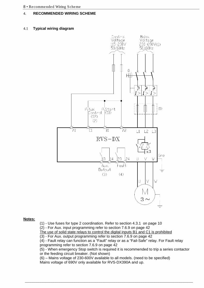
4. RECOMMENDED WIRING SCHEME 4.1 Typical wiring diagram
Notes:
(1) - Use fuses for type 2 coordination. Refer to section 4.3.1 on page 10 (2) - For Aux. input programming refer to section 7.6.9 on page 42
The use of solid state relays to control the digital inputs B1 and C1 is prohibited (3) - For Aux. output programming refer to section 7.6.9 on page 42
(4) - Fault relay can function as a “Fault” relay or as a “Fail-Safe” relay. For Fault relay programming refer to section 7.6.9 on page 42 (5) - When emergency Stop switch is required it is recommended to trip a series contactor or the feeding circuit breaker. (Not shown) (6) – Mains voltage of 230-600V available to all models. (need to be specified) Mains voltage of 690V only available for RVS-DX390A and up.
9 • Recommended Wiring Scheme
___________________________________________________________________________________________
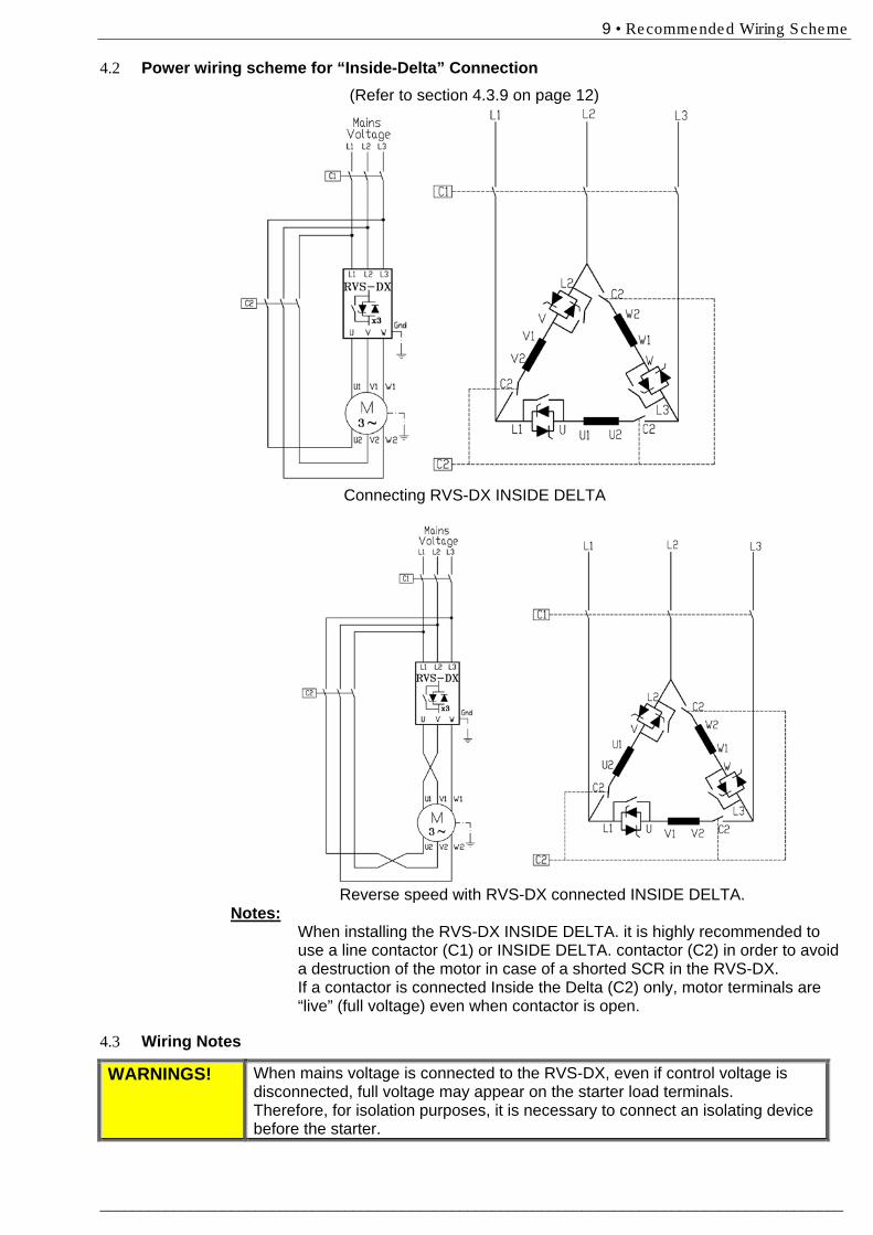
4.2 Power wiring scheme for “Inside-Delta” Connection (Refer to section 4.3.9 on page 12)
Connecting RVS-DX INSIDE DELTA
Reverse speed with RVS-DX connected INSIDE DELTA.
Notes: When installing the RVS-DX INSIDE DELTA. it is highly recommended to
use a line contactor (C1) or INSIDE DELTA. contactor (C2) in order to avoid a destruction of the motor in case of a shorted SCR in the RVS-DX. If a contactor is connected Inside the Delta (C2) only, motor terminals are “live” (full voltage) even when contactor is open.
4.3 88BWiring Notes
WARNINGS! When mains voltage is connected to the RVS-DX, even if control voltage is disconnected, full voltage may appear on the starter load terminals. Therefore, for isolation purposes, it is necessary to connect an isolating device before the starter.
10 • Recommended Wiring Scheme
________________________________________________________________________________________
Power factor correction capacitors and overvoltage devices must not be installed on starters load side. When required, install capacitors or overvoltage devices on starter’s line side.
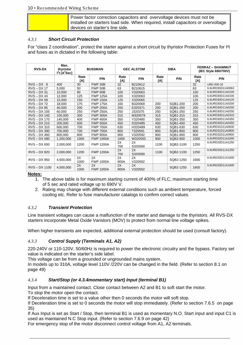
4.3.1 Short Circuit Protection For “class 2 coordination”, protect the starter against a short circuit by thyristor Protection Fuses for I²t and fuses as in dictated in the following table:
Notes: 1. The above table is for maximum starting current of 400% of FLC, maximum starting time
of 5 sec and rated voltage up to 690V V. 2. Rating may change with different external conditions such as ambient temperature, forced
cooling etc. Refer to fuse manufacturer catalogs to confirm correct values. 4.3.2 Transient Protection Line transient voltages can cause a malfunction of the starter and damage to the thyristors. All RVS-DX starters incorporate Metal Oxide Varistors (MOV) to protect from normal line voltage spikes. When higher transients are expected, additional external protection should be used (consult factory). 4.3.3 Control Supply (Terminals A1, A2) 220-240V or 110-120V, 50/60Hz is required to power the electronic circuitry and the bypass. Factory set value is indicated on the starter’s side label. This voltage can be from a grounded or ungrounded mains system. In models up to 310A, voltage level 110V /220V can be changed in the field. (Refer to section 8.1 on page 49) 4.3.4 Start/Stop (or 4.3.4momentary start) Input (terminal B1) Input from a maintained contact. Close contact between A2 and B1 to soft start the motor. To stop the motor open the contact. If Deceleration time is set to a value other then 0 seconds the motor will soft stop. If Deceleration time is set to 0 seconds the motor will stop immediately. (Refer to section 7.6.5 on page 35) If Aux Input is set as Start / Stop, then terminal B1 is used as momentary N.O. Start input and input C1 is used as maintained N.C Stop input. (Refer to section 7.6.9 on page 42) For emergency stop of the motor disconnect control voltage from A1, A2 terminals.
RVS-DX Max.
thyristor I2t [A2Sec]
BUSSMAN GEC ALSTOM SIBA FERRAZ – SHAWMUT (IEC Style 690/700V)
Rate [A] P/N Rate
[A] P/N Rate [A] P/N Rate
[A] P/N
RVS – DX 8 400 30 FWP 30B 32 B210612 32 URD 000-32 RVS – DX 17 5,000 50 FWP 50B 63 B210615 63 6.6URD30D11A0063 RVS – DX 31 10,000 90 FWP 90B 100 V320063 100 6.6URD30D11A0100 RVS – DX 44 12,000 125 FWP 125A 100 X320063 100 6.6URD30D11A0100 RVS – DX 58 15,000 150 FWP 150A 125 X320065 125 6.6URD30D11A0125 RVS – DX 72 18,000 175 FWP 175A 160 B320069 200 SQB1-200 200 6.6URD30D11A0200 RVS – DX 85 40,000 200 FWP 200A 200 E320371 200 SQB1-200 200 6.6URD30D11A0200 RVS – DX 105 60,000 250 FWP 250A. 250 J320375 250 SQB1-250 250 6.6URD30D11A0250 RVS – DX 145 100,000 300 FWP 300A 315 M320079 315 SQB1-315 315 6.6URD30D11A0315 RVS – DX 170 140,000 400 FWP 400A 350 Y320480 350 SQB1-350 350 6.6URD30D11A0350 RVS – DX 210 200,000 500 FWP 500A 450 D320485 450 SQB1-450 450 6.6URD30D11A0450 RVS – DX 310 600,000 700 FWP 700A 630 H320489 630 SQB1-630 630 6.6URD31D11A0630 RVS – DX 390 700,000 700 FWP 700A 800 T320591 800 SQB1-800 800 6.6URD31D11A0800 RVS – DX 460 800,000 800 FWP 800A 900 V320592 900 SQB1-900 900 6.6URD32D11A0900 RVS – DX 580 1,200,000 1000 FWP 1000A 1000 W320593 900 SQB2-900 1000 6.6URD32D11A1000
RVS – DX 650 2,000,000 1200 FWP 1200A 2X 700
2X S320590 1100 SQB2-1100 1250
6.6URD33D11A1250
RVS – DX 820 2,000,000 1200 FWP 1200A 2X 700
2X S320590 1100 SQB2-1100 1250
6.6URD33D11A1250
RVS – DX 950 4,500,000 2X 1000
2X FWP 1000A
2X 900A
2X V320592 SQB2-1250 1600
6.6URD33D11A1600
RVS – DX 1100 4,500,000 2X 1000
2X FWP 1000A
2X 900A
2X V320592 SQB2-1250 1600
6.6URD33D11A1600
11 • Recommended Wiring Scheme
___________________________________________________________________________________________
4.3.5 Aux. Input (terminal C1) Input from a maintained contact, connected between terminals A2 and C1 to operate as programmed input. Aux. Input can be programmed as one of six options:
(1) Dual Adjust (2) Generator Function (3) Slow Speed / Reverse (4) External fault (5) Remote reset after fault has been removed. (6) Start / Stop (terminal C1 can be used as a maintained N.C Stop input and terminal B1 as
momentary N.O. Start input – refer also to section 4.3.4 above.
For Aux. Input programming refer to section 7.6.9 on page 42. 4.3.6 Auxiliary output relay (terminals 13, 14) Voltage free, N.O , 8A, 250VAC, 1800VA max. The contact incorporates 0-60 seconds On & Off delays. The auxiliary output relay can be programmed to operate in two modes: 1. IMMEDIATE - Close its contact at start signal (after programmed “on delay” time has elapsed) and open its contact at the end of deceleration time (if any) (after programmed “off delay” time has elapsed). 2. END OF ACCEL. - Close its contact at end of soft start (after programmed “on delay” time has elapsed) and open its contact at the beginning of soft stop (if any) (after programmed “off delay” time has elapsed). The relay contact will open also in case of a fault or upon control supply outage. This output is generally used to:
(1) Release the brake of a brake motor. (2) Interlocking with other systems. (3) Signalling.
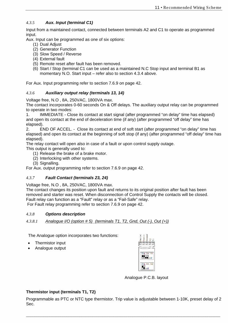
For Aux. output programming refer to section 7.6.9 on page 42. 4.3.7 Fault Contact (terminals 23, 24) Voltage free, N.O , 8A, 250VAC, 1800VA max. The contact changes its position upon fault and returns to its original position after fault has been removed and starter was reset. When disconnection of Control Supply the contacts will be closed. Fault relay can function as a “Fault” relay or as a “Fail-Safe” relay. For Fault relay programming refer to section 7.6.9 on page 42. 4.3.8 Options description 4.3.8.1 Analogue I/O (option # 5) (terminals T1, T2, Gnd, Out (-), Out (+))
The Analogue option incorporates two functions:
• Thermistor input • Analogue output
Analogue P.C.B. layout
Thermistor input (terminals T1, T2) Programmable as PTC or NTC type thermistor. Trip value is adjustable between 1-10K, preset delay of 2 Sec.
12 • Recommended Wiring Scheme
________________________________________________________________________________________
For thermistor input programming refer to section 7.6.8 on page 40.
Ground Terminal (terminal Gnd) Connect thermistor and / or Analogue output shield to this ground terminal.
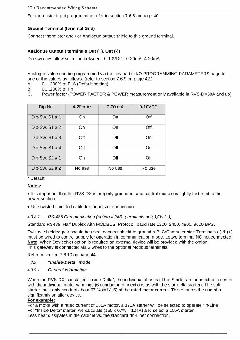
Analogue Output ( terminals Out (+), Out (-)) Dip switches allow selection between: 0-10VDC, 0-20mA, 4-20mA
Analogue value can be programmed via the key pad in I/O PROGRAMMING PARAMETERS page to one of the values as follows: (refer to section 7.6.9 on page 42.) A. 0….200% of FLA (Default setting) B. 0….200% of Pn C. Power factor (POWER FACTOR & POWER measurement only available in RVS-DX58A and up)
Dip No. 4-20 mA* 0-20 mA 0-10VDC
Dip-Sw. S1 # 1 On On Off
Dip-Sw. S1 # 2 On On Off
Dip-Sw. S1 # 3 Off Off On
Dip-Sw. S1 # 4 Off Off On
Dip-Sw. S2 # 1 On Off Off
Dip-Sw. S2 # 2 No use No use No use
* Default
Notes:
• It is important that the RVS-DX is properly grounded, and control module is tightly fastened to the power section.
• Use twisted shielded cable for thermistor connection. 4.3.8.2 RS-485 Communication (option # 3M) (terminals out(-),Out(+))
Standard RS485, Half Duplex with MODBUS Protocol, baud rate 1200, 2400, 4800, 9600 BPS.
Twisted shielded pair should be used, connect shield to ground a PLC/Computer side.Terminals (-) & (+) must be wired to control supply for operation in communication mode. Leave terminal NC not connected. Note: When DeviceNet option is required an external device will be provided with the option. This gateway is connected via 2 wires to the optional Modbus terminals.
Refer to section 7.6.10 on page 44.
4.3.9 “Inside-Delta” mode 4.3.9.1 General information
When the RVS-DX is installed “Inside Delta”, the individual phases of the Starter are connected in series with the individual motor windings (6 conductor connections as with the star-delta starter). The soft starter must only conduct about 67 % (=1\1.5) of the rated motor current. This ensures the use of a significantly smaller device. For example: For a motor with a rated current of 155A motor, a 170A starter will be selected to operate “In-Line”. For “Inside Delta” starter, we calculate (155 x 67% = 104A) and select a 105A starter. Less heat dissipates in the cabinet vs. the standard “In-Line” connection.
13 • Recommended Wiring Scheme
___________________________________________________________________________________________
4.3.9.2 Notes on “Inside Delta” connection
• “Inside Delta” requires 6-wire to the motor. • Wrong motor connection will cause serious damage to the motor windings. • When installing the RVS-DX “inside delta” it is highly recommended to use a contactor in
series to the RVS-DX or upstream (after motor protection) in order to avoid a destruction of the motor in case of a shorted SCR in the RVS-DX.
• The sinusoidal shape of the current is imperfect (since each phase is separately fired and not influenced by other phase firing). As a result, higher harmonic content is incurred (THD), which can be as high as twice the THD value as in the standard “In-Line”.
• Higher motor heating is expected for the same motor size (due to the higher THD). • Phase sequence must be correct; otherwise, “Phase Sequence fault” will trip the starter
immediately (without any damage). • Higher torques can not be obtained • Factory preset - features and functions when “Inside Delta” mode is configured:
o No Pulse Start. o No curve selection (Curve 0 !! only). o No Slow Speed o No Phase sequence “Off” mode
Note : For a high starting torque process, it is recommended to use the starter in the “In Line” connection. WARNINGS! Beware!
Wrong connection of the starter or the Motor, will seriously damage the motor. When using “Inside delta” connection: 1. It is highly recommended to use a contactor in series to the RVS-DX or upstream (after motor protection) in order to avoid a destruction of the motor in case of a shorted SCR in the RVS-DX. 2. If Contactor is connected Inside the Delta, motor terminals are “live” (full voltage) even when contactor is open.
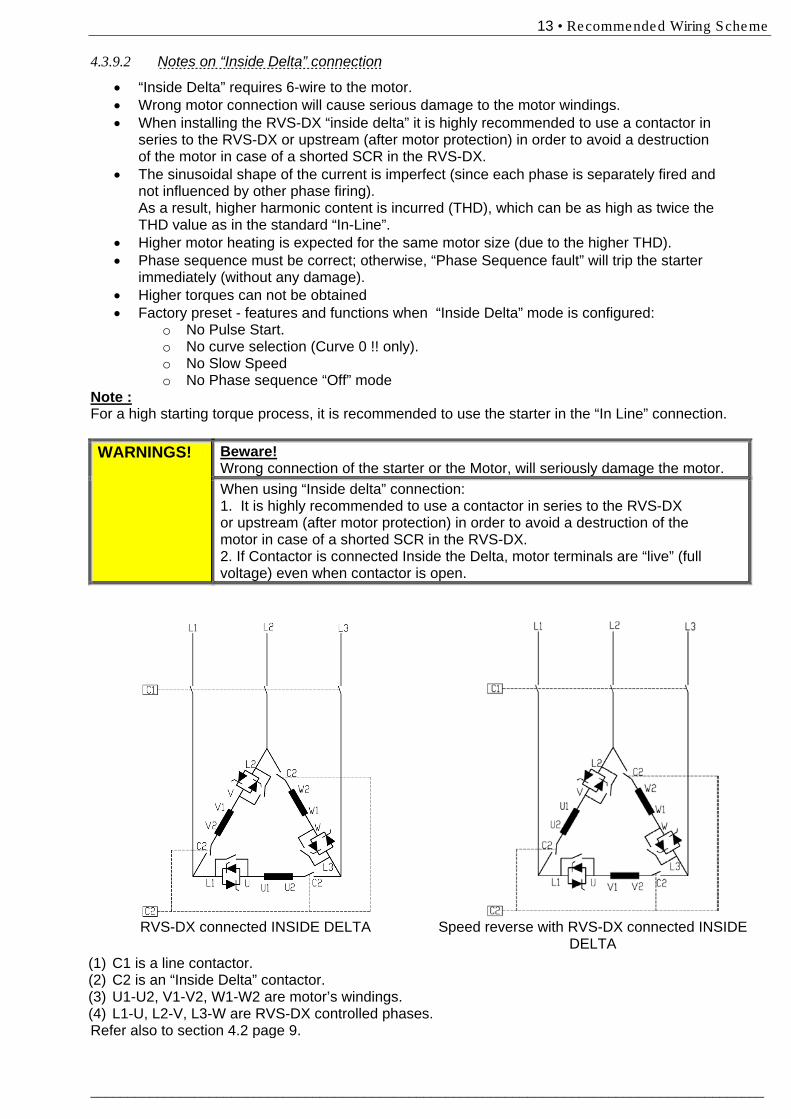
RVS-DX connected INSIDE DELTA Speed reverse with RVS-DX connected INSIDE
DELTA (1) C1 is a line contactor. (2) C2 is an “Inside Delta” contactor. (3) U1-U2, V1-V2, W1-W2 are motor’s windings. (4) L1-U, L2-V, L3-W are RVS-DX controlled phases. Refer also to section 4.2 page 9.
14 • Dimens ions
________________________________________________________________________________________
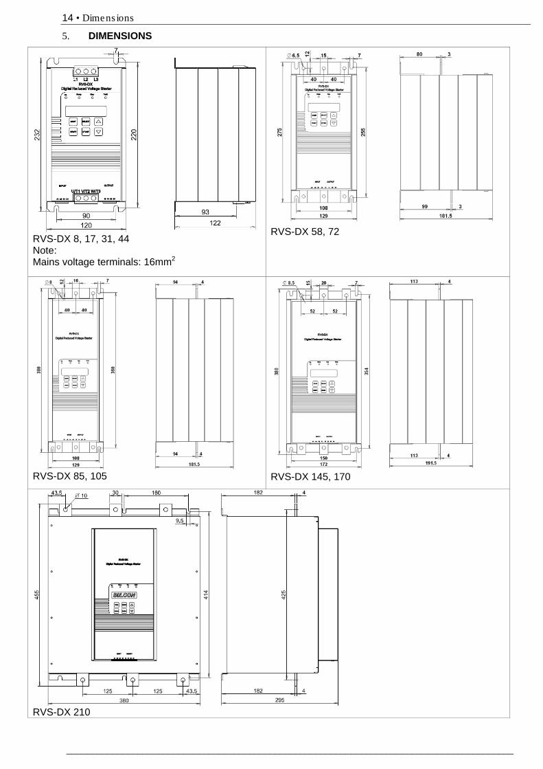
5. DIMENSIONS
RVS-DX 8, 17, 31, 44 Note: Mains voltage terminals: 16mm2
RVS-DX 58, 72
RVS-DX 85, 105
RVS-DX 145, 170
RVS-DX 210
15 • Dimens ions
___________________________________________________________________________________________
RVS-DX 310
RVS-DX 390
16 • Dimens ions
________________________________________________________________________________________
RVS-DX 460
RVS-DX 580
17 • Dimens ions
___________________________________________________________________________________________
RVS-DX 650-820
RVS-DX 950-1100
18 • Ins ta lla tion
________________________________________________________________________________________
Area (m2) =
6. INSTALLATION
WARNING! Do not interchange line and load connections
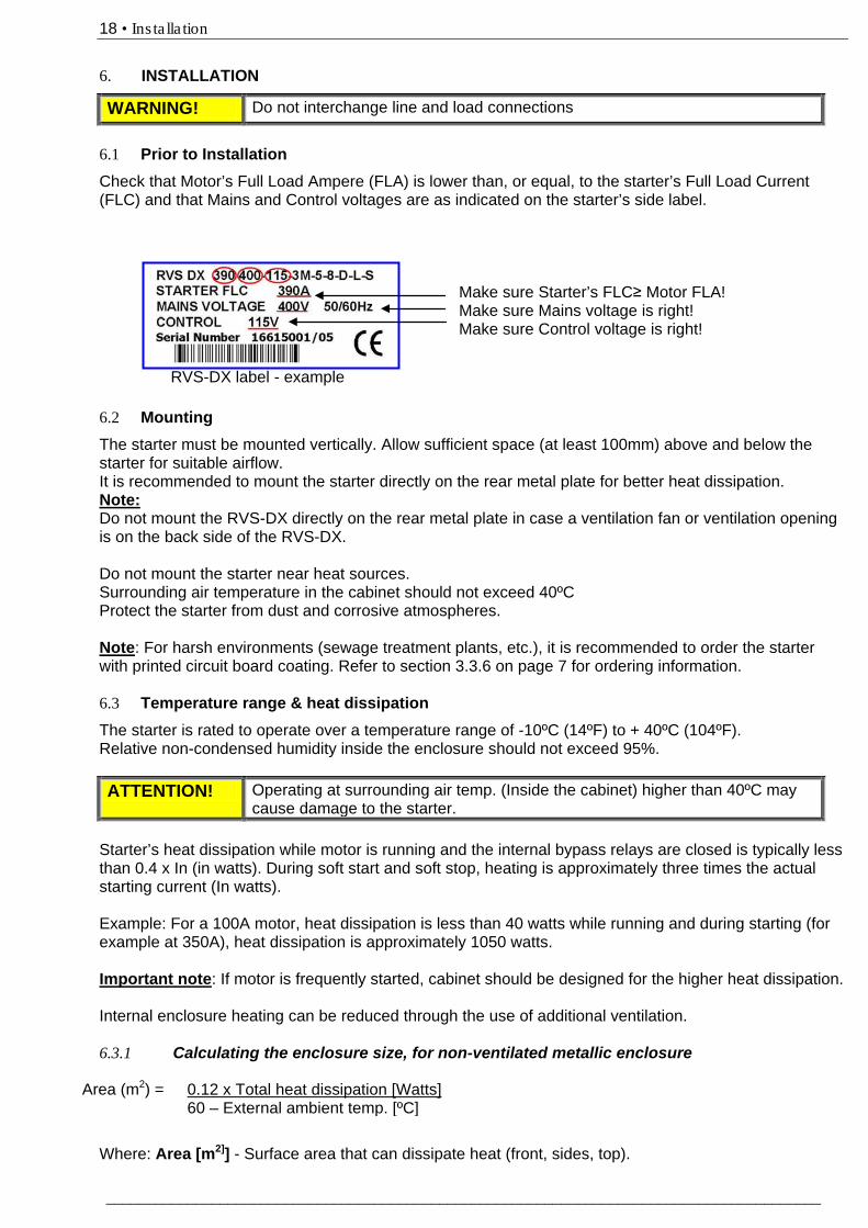
6.1 89BPrior to Installation Check that Motor’s Full Load Ampere (FLA) is lower than, or equal, to the starter’s Full Load Current (FLC) and that Mains and Control voltages are as indicated on the starter’s side label.
Make sure Starter’s FLC≥ Motor FLA! Make sure Mains voltage is right! Make sure Control voltage is right!
RVS-DX label - example 6.2 90BMounting The starter must be mounted vertically. Allow sufficient space (at least 100mm) above and below the starter for suitable airflow. It is recommended to mount the starter directly on the rear metal plate for better heat dissipation. Note: Do not mount the RVS-DX directly on the rear metal plate in case a ventilation fan or ventilation opening is on the back side of the RVS-DX. Do not mount the starter near heat sources. Surrounding air temperature in the cabinet should not exceed 40ºC Protect the starter from dust and corrosive atmospheres. Note: For harsh environments (sewage treatment plants, etc.), it is recommended to order the starter with printed circuit board coating. Refer to section 3.3.6 on page 7 for ordering information. 6.3 91BTemperature range & heat dissipation The starter is rated to operate over a temperature range of -10ºC (14ºF) to + 40ºC (104ºF). Relative non-condensed humidity inside the enclosure should not exceed 95%. ATTENTION! Operating at surrounding air temp. (Inside the cabinet) higher than 40ºC may
cause damage to the starter. Starter’s heat dissipation while motor is running and the internal bypass relays are closed is typically less than 0.4 x In (in watts). During soft start and soft stop, heating is approximately three times the actual starting current (In watts). Example: For a 100A motor, heat dissipation is less than 40 watts while running and during starting (for example at 350A), heat dissipation is approximately 1050 watts. Important note: If motor is frequently started, cabinet should be designed for the higher heat dissipation. Internal enclosure heating can be reduced through the use of additional ventilation. 6.3.1 119BCalculating the enclosure size, for non-ventilated metallic enclosure Where: Area [m2]] - Surface area that can dissipate heat (front, sides, top).
0.12 x Total heat dissipation [Watts] 60 – External ambient temp. [ºC]
19 • Ins ta lla tion
___________________________________________________________________________________________
Total heat dissipation [Watt] – The total heat dissipation of the starter and other control devices in the enclosure. If starter is frequently started, average power should be used.
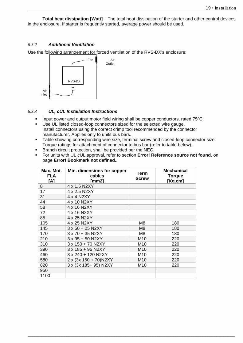
6.3.2 Additional Ventilation Use the following arrangement for forced ventilation of the RVS-DX’s enclosure: 6.3.3 UL, cUL Installation Instructions Input power and output motor field wiring shall be copper conductors, rated 75ºC. Use UL listed closed-loop connectors sized for the selected wire gauge.
Install connectors using the correct crimp tool recommended by the connector manufacturer. Applies only to units bus bars.
Table showing corresponding wire size, terminal screw and closed-loop connector size. Torque ratings for attachment of connector to bus bar (refer to table below).
Branch circuit protection, shall be provided per the NEC. For units with UL cUL approval, refer to section Error! Reference source not found. on
page Error! Bookmark not defined..
Max. Mot. FLA [A]
Min. dimensions for copper cables [mm2]
Term Screw
Mechanical Torque [Kg.cm]
8 4 x 1.5 N2XY 17 4 x 2.5 N2XY 31 4 x 4 N2XY 44 4 x 10 N2XY 58 4 x 16 N2XY 72 4 x 16 N2XY 85 4 x 25 N2XY 105 4 x 25 N2XY M8 180 145 3 x 50 + 25 N2XY M8 180 170 3 x 70 + 35 N2XY M8 180 210 3 x 95 + 50 N2XY M10 220 310 3 x 150 + 70 N2XY M10 220 390 3 x 185 + 95 N2XY M10 220 460 3 x 240 + 120 N2XY M10 220 580 2 x (3x 150 + 70)N2XY M10 220 820 3 x (3x 185+ 95) N2XY M10 220 950 1100
Air Outlet
Air Inlet
Air Inlet
Fan
RVS-DX
20 • Control Keypad
________________________________________________________________________________________
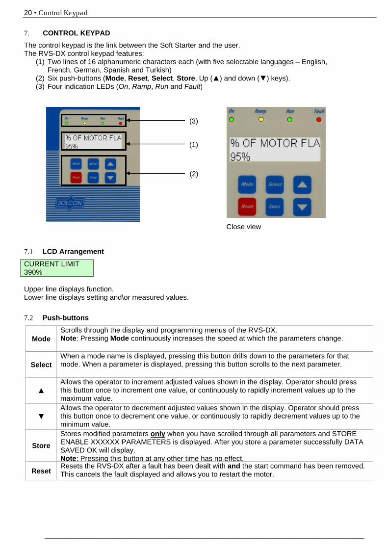
7. CONTROL KEYPAD The control keypad is the link between the Soft Starter and the user. The RVS-DX control keypad features:
(1) Two lines of 16 alphanumeric characters each (with five selectable languages – English, French, German, Spanish and Turkish)
(2) Six push-buttons (Mode, Reset, Select, Store, Up (▲) and down (▼) keys). (3) Four indication LEDs (On, Ramp, Run and Fault)
Close view 7.1 92BLCD Arrangement CURRENT LIMIT 390% Upper line displays function. Lower line displays setting and\or measured values. 7.2 93BPush-buttons
Mode Scrolls through the display and programming menus of the RVS-DX. 50BNote: Pressing Mode continuously increases the speed at which the parameters change.
Select When a mode name is displayed, pressing this button drills down to the parameters for that mode. When a parameter is displayed, pressing this button scrolls to the next parameter.
▲ Allows the operator to increment adjusted values shown in the display. Operator should press this button once to increment one value, or continuously to rapidly increment values up to the maximum value.
▼ Allows the operator to decrement adjusted values shown in the display. Operator should press this button once to decrement one value, or continuously to rapidly decrement values up to the minimum value.
Store Stores modified parameters only when you have scrolled through all parameters and STORE ENABLE XXXXXX PARAMETERS is displayed. After you store a parameter successfully DATA SAVED OK will display. Note: Pressing this button at any other time has no effect. Reset Resets the RVS-DX after a fault has been dealt with and the start command has been removed. This cancels the fault displayed and allows you to restart the motor.
(2)
(3)
(1)
21 • Control Keypad
___________________________________________________________________________________________
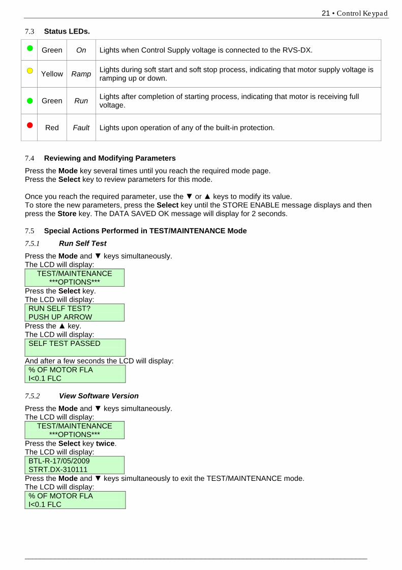
7.3 Status LEDs.
Green On Lights when Control Supply voltage is connected to the RVS-DX.
Yellow Ramp Lights during soft start and soft stop process, indicating that motor supply voltage is
ramping up or down.
Green Run Lights after completion of starting process, indicating that motor is receiving full
voltage.
Red Fault Lights upon operation of any of the built-in protection.
7.4 Reviewing and Modifying Parameters Press the Mode key several times until you reach the required mode page. Press the Select key to review parameters for this mode. Once you reach the required parameter, use the ▼ or ▲ keys to modify its value. To store the new parameters, press the Select key until the STORE ENABLE message displays and then press the Store key. The DATA SAVED OK message will display for 2 seconds. 7.5 Special Actions Performed in TEST/MAINTENANCE Mode 7.5.1 Run Self Test Press the Mode and ▼ keys simultaneously. The LCD will display:
TEST/MAINTENANCE ***OPTIONS***
Press the Select key. The LCD will display: RUN SELF TEST? PUSH UP ARROW
Press the ▲ key. The LCD will display: SELF TEST PASSED
And after a few seconds the LCD will display: % OF MOTOR FLA I<0.1 FLC
7.5.2 View Software Version Press the Mode and ▼ keys simultaneously. The LCD will display:
TEST/MAINTENANCE ***OPTIONS***
Press the Select key twice. The LCD will display: BTL-R-17/05/2009 STRT.DX-310111
Press the Mode and ▼ keys simultaneously to exit the TEST/MAINTENANCE mode. The LCD will display: % OF MOTOR FLA I<0.1 FLC

22 • Control Keypad
________________________________________________________________________________________
7.5.3 Obtain Default Parameters Press the Mode and ▼ keys simultaneously. The LCD will display:
TEST/MAINTENANCE ***OPTIONS***
Press the Select key three times. The LCD will display: STORE ENABLE DEFAULT PARAMET.
Press the Store + Mode keys simultaneously. The LCD will display: DATA SAVED OK
And after a few seconds the LCD will display: % OF MOTOR FLA I<0.1 FLC
CAUTION! Obtaining DEFAULT PARAMETERS erases all previously modified settings
and requires the operator to reprogram all parameters that differ from the factory default. Note: It is especially important to reprogram the FLC (as shown on the label of the RVS-DX), FLA and RATED LINE VOLT. value again.
7.5.4 Reset Statistical Data Press the Mode and ▼ keys simultaneously. The LCD will display:
TEST/MAINTENANCE ***OPTIONS***
Press the Select key four times. The LCD will display: RESET STATISTICS
Press the Reset + Store keys simultaneously. The LCD will display: DATA SAVED OK
And after a few seconds the LCD will display: STATISTICAL DATA - **** -
Press the Mode and go back to: % OF MOTOR FLA I<0.1 FLC
23 • Control Keypad
___________________________________________________________________________________________
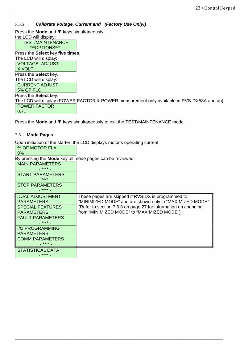
7.5.5 Calibrate Voltage, Current and (Factory Use Only!) Press the Mode and ▼ keys simultaneously. the LCD will display:
TEST/MAINTENANCE ***OPTIONS***.
Press the Select key five times. The LCD will display: VOLTAGE ADJUST. X VOLT
Press the Select key. The LCD will display: CURRENT ADJUST. 5% OF FLC
Press the Select key. The LCD will display (POWER FACTOR & POWER measurement only available in RVS-DX58A and up): POWER FACTOR 0.71
Press the Mode and ▼ keys simultaneously to exit the TEST/MAINTENANCE mode. 7.6 Mode Pages Upon initiation of the starter, the LCD displays motor’s operating current: % OF MOTOR FLA 0%
By pressing the Mode key all mode pages can be reviewed: MAIN PARAMETERS - **** - START PARAMETERS - **** - STOP PARAMETERS - **** - DUAL ADJUSTMENT PARAMETERS
These pages are skipped if RVS-DX is programmed to “MINIMIZED MODE” and are shown only in “MAXIMIZED MODE” (Refer to section 7.6.3 on page 27 for information on changing from “MINIMIZED MODE” to “MAXIMIZED MODE”)
SPECIAL FEATURES PARAMETERS FAULT PARAMETERS - **** - I/O PROGRAMMING PARAMETERS COMM PARAMETERS - **** - STATISTICAL DATA - **** -

24 • Control Keypad
________________________________________________________________________________________
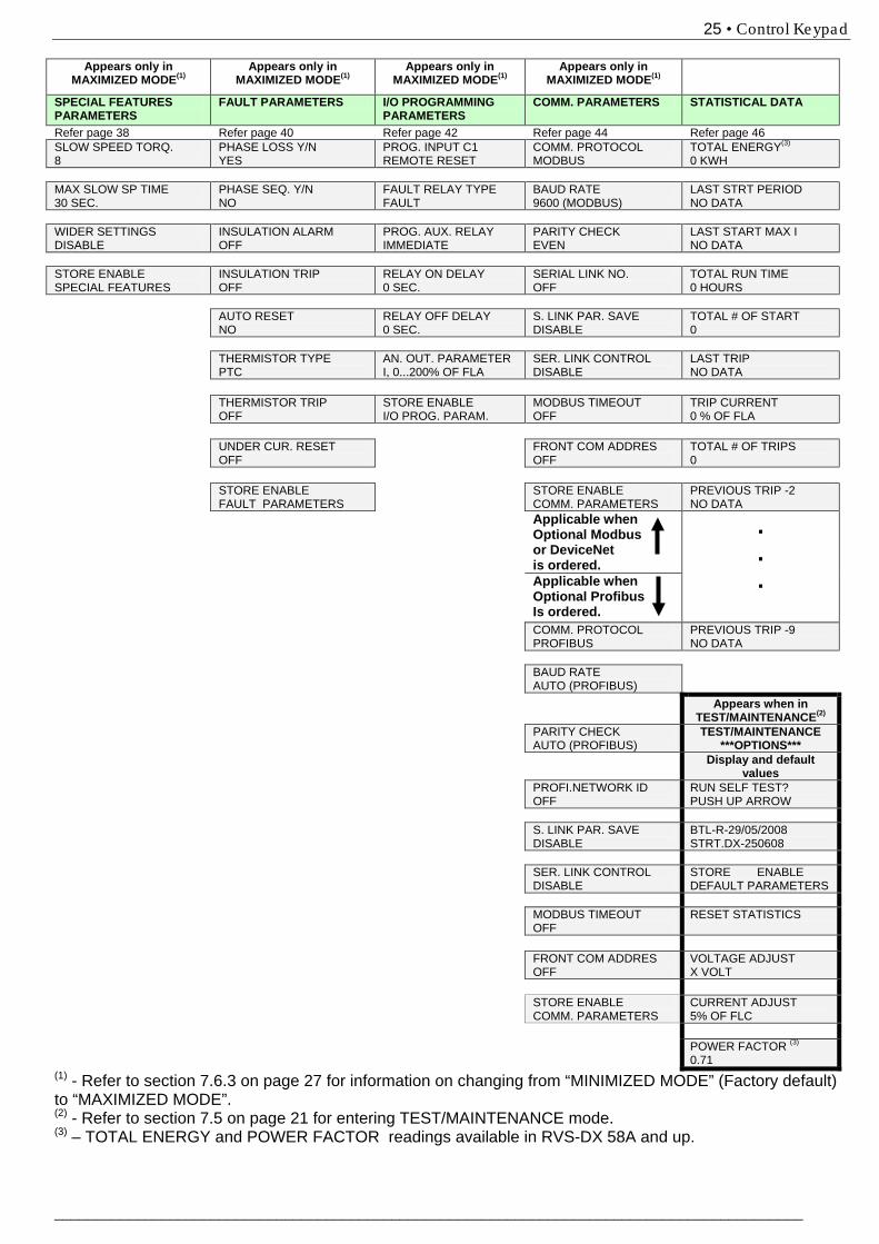
7.6.1 Overview of All Mode Pages and Factory Defaults Appears only in
MAXIMIZED MODE(1) % OF MOTOR FLA XX%
MAIN PARAMETERS START PARAMETERS
STOP PARAMETERS
DUAL ADJUSTMENT PARAMETERS
Refer page 26 Refer page 27 Refer page 31 Refer page 35 Refer page 37 AMP. VOLT 0 0
LANGUAGE: ENGLISH
SOFT START CURVE 0(STANDARD)
SOFT STOP CURVE 0(STANDARD)
DA: INIT. VOLT. 30%
OPTION CARD Not Installed
STARTER FLC 58 AMP.
PULSE TIME 0 SEC.
DEC. TIME 0 SEC.
DA: CUR. LIMIT 400% OF FLA
POWER (2) MOTOR FLA
58 AMP. INITIAL VOLTAGE 30 %
FINAL TORQUE 0 (MIN.)
DA: ACC. TIME 10 SEC.
POWER FACTOR (2) RATED POWER
30KW CURRENT LIMIT 400% OF FLA
STORE ENABLE STOP PARAMETERS
DA: DEC. TIME 0 SEC.
CONNECTION TYPE
LINE ACC. TIME 10 SEC.
DA: MOTOR FLA 31 AMP.
RATED LINE VOLT.
400 VOLT MAX. START TIME 30 SEC.
STORE ENABLE D. ADJ PARAMETERS
UNDERCURR. TRIP
0% OF FLA NUMBER OF STARTS 10
UNDERCURR. DELAY
10 SEC. STARTS PERIOD 30 MIN.
O/C – SHEAR PIN
200% OF FLA START INHIBIT 15 MIN.
O/C DELAY
0.5 SEC. STORE ENABLE START PARAMETERS
OVERLOAD CLASS
IEC CLASS 10
OVERLOAD PROTECT
ENABLE WHILE RUN
UNDERVOLT. TRIP
75%
UNDERVOLT. DELAY
5 SEC.
OVERVOLT. TRIP
120 %
OVERVOLT. DELAY
2 SEC.
DISPLAY MODE
MINIMIZED
PARAMETERS LOCK
NOT LOCKED
STORE ENABLE
MAIN PARAMETERS
(1) - Refer to section 7.6.3 on page 27 for information on changing from “MINIMIZED MODE” (Factory default) to “MAXIMIZED MODE”.
(2) POWER and POWER FACTOR readings available in RVS-DX 58A and up.
25 • Control Keypad
___________________________________________________________________________________________
Appears only in MAXIMIZED MODE(1)
Appears only in MAXIMIZED MODE(1)
Appears only in MAXIMIZED MODE(1)
Appears only in MAXIMIZED MODE(1)
SPECIAL FEATURES PARAMETERS
FAULT PARAMETERS I/O PROGRAMMING PARAMETERS
COMM. PARAMETERS STATISTICAL DATA
Refer page 38 Refer page 40 Refer page 42 Refer page 44 Refer page 46 SLOW SPEED TORQ. 8
PHASE LOSS Y/N YES
PROG. INPUT C1 REMOTE RESET
COMM. PROTOCOL MODBUS
TOTAL ENERGY(3) 0 KWH
MAX SLOW SP TIME 30 SEC.
PHASE SEQ. Y/N NO
FAULT RELAY TYPE FAULT
BAUD RATE 9600 (MODBUS)
LAST STRT PERIOD NO DATA
WIDER SETTINGS DISABLE
INSULATION ALARM OFF
PROG. AUX. RELAY IMMEDIATE
PARITY CHECK EVEN
LAST START MAX I NO DATA
STORE ENABLE SPECIAL FEATURES
INSULATION TRIP OFF
RELAY ON DELAY 0 SEC.
SERIAL LINK NO. OFF
TOTAL RUN TIME 0 HOURS
AUTO RESET
NO RELAY OFF DELAY 0 SEC.
S. LINK PAR. SAVE DISABLE
TOTAL # OF START 0
THERMISTOR TYPE
PTC AN. OUT. PARAMETER I, 0...200% OF FLA
SER. LINK CONTROL DISABLE
LAST TRIP NO DATA
THERMISTOR TRIP
OFF STORE ENABLE I/O PROG. PARAM.
MODBUS TIMEOUT OFF
TRIP CURRENT 0 % OF FLA
UNDER CUR. RESET
OFF FRONT COM ADDRES
OFF TOTAL # OF TRIPS 0
STORE ENABLE
FAULT PARAMETERS STORE ENABLE
COMM. PARAMETERS PREVIOUS TRIP -2 NO DATA
Applicable when Optional Modbus or DeviceNet is ordered.
.
.
. Applicable when Optional Profibus Is ordered.
COMM. PROTOCOL PROFIBUS
PREVIOUS TRIP -9 NO DATA
BAUD RATE
AUTO (PROFIBUS)
Appears when in TEST/MAINTENANCE(2)
PARITY CHECK AUTO (PROFIBUS)
TEST/MAINTENANCE ***OPTIONS***
Display and default values
PROFI.NETWORK ID OFF
RUN SELF TEST? PUSH UP ARROW
S. LINK PAR. SAVE
DISABLE BTL-R-29/05/2008 STRT.DX-250608
SER. LINK CONTROL
DISABLE STORE ENABLE DEFAULT PARAMETERS
MODBUS TIMEOUT
OFF RESET STATISTICS
FRONT COM ADDRES
OFF VOLTAGE ADJUST X VOLT
STORE ENABLE
COMM. PARAMETERS CURRENT ADJUST 5% OF FLC
POWER FACTOR (3)
0.71 (1) - Refer to section 7.6.3 on page 27 for information on changing from “MINIMIZED MODE” (Factory default) to “MAXIMIZED MODE”. (2) - Refer to section 7.5 on page 21 for entering TEST/MAINTENANCE mode. (3) – TOTAL ENERGY and POWER FACTOR readings available in RVS-DX 58A and up.
26 • Control Keypad
________________________________________________________________________________________
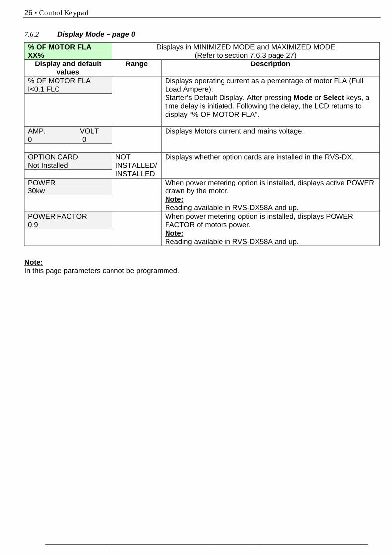
7.6.2 Display Mode – page 0
% OF MOTOR FLA XX%
Displays in MINIMIZED MODE and MAXIMIZED MODE (Refer to section 7.6.3 page 27)
Display and default values
Range Description
% OF MOTOR FLA I<0.1 FLC
Displays operating current as a percentage of motor FLA (Full Load Ampere). Starter’s Default Display. After pressing Mode or Select keys, a time delay is initiated. Following the delay, the LCD returns to display “% OF MOTOR FLA”.
AMP. VOLT 0 0
Displays Motors current and mains voltage.
OPTION CARD Not Installed
NOT INSTALLED/ INSTALLED
Displays whether option cards are installed in the RVS-DX.
POWER 30kw
When power metering option is installed, displays active POWER drawn by the motor. Note: Reading available in RVS-DX58A and up.
POWER FACTOR 0.9
When power metering option is installed, displays POWER FACTOR of motors power. Note: Reading available in RVS-DX58A and up.
Note: In this page parameters cannot be programmed.
27 • Control Keypad
___________________________________________________________________________________________
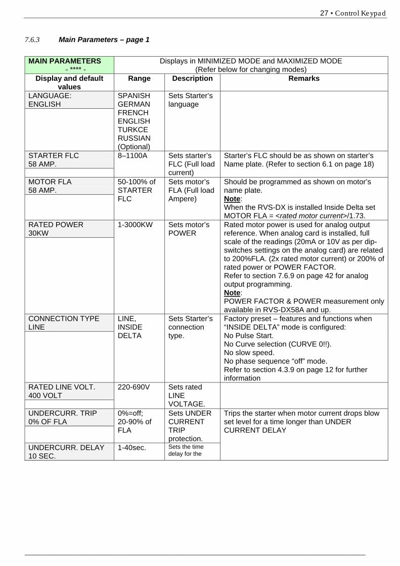
7.6.3 Main Parameters – page 1 MAIN PARAMETERS - **** -
Displays in MINIMIZED MODE and MAXIMIZED MODE (Refer below for changing modes)
Display and default values
Range Description Remarks
LANGUAGE: ENGLISH
SPANISH GERMAN FRENCH ENGLISH TURKCE RUSSIAN (Optional)
Sets Starter’s language
STARTER FLC 58 AMP.
8–1100A Sets starter’s FLC (Full load current)
Starter’s FLC should be as shown on starter’s Name plate. (Refer to section 6.1 on page 18)
MOTOR FLA 58 AMP.
50-100% of STARTER FLC
Sets motor’s FLA (Full load Ampere)
Should be programmed as shown on motor’s name plate. Note: When the RVS-DX is installed Inside Delta set MOTOR FLA = <rated motor current>/1.73.
RATED POWER 30KW
1-3000KW Sets motor’s POWER
Rated motor power is used for analog output reference. When analog card is installed, full scale of the readings (20mA or 10V as per dip-switches settings on the analog card) are related to 200%FLA. (2x rated motor current) or 200% of rated power or POWER FACTOR. Refer to section 7.6.9 on page 42 for analog output programming. Note: POWER FACTOR & POWER measurement only available in RVS-DX58A and up.
CONNECTION TYPE LINE
LINE, INSIDE DELTA
Sets Starter’s connection type.
Factory preset – features and functions when “INSIDE DELTA” mode is configured: No Pulse Start. No Curve selection (CURVE 0!!). No slow speed. No phase sequence “off” mode. Refer to section 4.3.9 on page 12 for further information
RATED LINE VOLT. 400 VOLT
220-690V Sets rated LINE VOLTAGE.
UNDERCURR. TRIP 0% OF FLA
0%=off; 20-90% of FLA
Sets UNDER CURRENT TRIP protection.
Trips the starter when motor current drops blow set level for a time longer than UNDER CURRENT DELAY
UNDERCURR. DELAY 10 SEC.
1-40sec. Sets the time delay for the
28 • Control Keypad
________________________________________________________________________________________
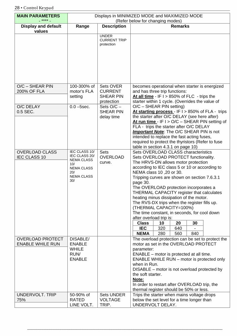
MAIN PARAMETERS - **** -
Displays in MINIMIZED MODE and MAXIMIZED MODE (Refer below for changing modes)
Display and default values
Range Description Remarks
UNDER CURRENT TRIP protection
O/C – SHEAR PIN 200% OF FLA
100-300% of motor’s FLA setting
Sets OVER CURRENT SHEAR PIN protection
becomes operational when starter is energized and has three trip functions: At all time - IF I > 850% of FLC - trips the starter within 1 cycle. (Overrides the value of O/C – SHEAR PIN setting) At starting process - IF I > 850% of FLA - trips the starter after O/C DELAY (see here after) At run time - IF I > O/C – SHEAR PIN setting of FLA - trips the starter after O/C DELAY Important Note: The O/C SHEAR PIN is not intended to replace the fast acting fuses, required to protect the thyristors (Refer to fuse table in section 4.3.1 on page 10)
O/C DELAY 0.5 SEC.
0.0 –5sec. Sets O/C – SHEAR PIN delay time
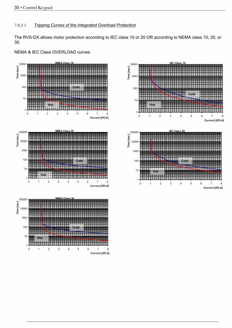
OVERLOAD CLASS IEC CLASS 10
IEC CLASS 10/ IEC CLASS 20/ NEMA CLASS 10/ NEMA CLASS 20/ NEMA CLASS 30/
Sets OVERLOAD curve.
Sets OVERLOAD CLASS characteristics Sets OVERLOAD PROTECT functionality. The HRVS-DN allows motor protection according to IEC class 5 or 10 or according to NEMA class 10 ,20 or 30. Tripping curves are shown on section 7.6.3.1 page 30. The OVERLOAD protection incorporates a THERMAL CAPACITY register that calculates heating minus dissipation of the motor. The RVS-DX trips when the register fills up. (THERMAL CAPACITY=100%) The time constant, in seconds, for cool down after overload trip is:
Class 10 20 30 IEC 320 640 -
NEMA 280 560 840
OVERLOAD PROTECT ENABLE WHILE RUN
DISABLE/ ENABLE WHILE RUN/ ENABLE
The overload protection can be set to protect the motor as set in the OVERLOAD PROTECT parameter: ENABLE – motor is protected at all time. ENABLE WHILE RUN – motor is protected only when in Run. DISABLE – motor is not overload protected by the soft starter. Note: In order to restart after OVERLOAD trip, the thermal register should be 50% or less.
UNDERVOLT. TRIP 75%
50-90% of RATED LINE VOLT.
Sets UNDER VOLTAGE TRIP.
Trips the starter when mains voltage drops below the set level for a time longer than UNDERVOLT DELAY.
29 • Control Keypad
___________________________________________________________________________________________
MAIN PARAMETERS - **** -
Displays in MINIMIZED MODE and MAXIMIZED MODE (Refer below for changing modes)
Display and default values
Range Description Remarks
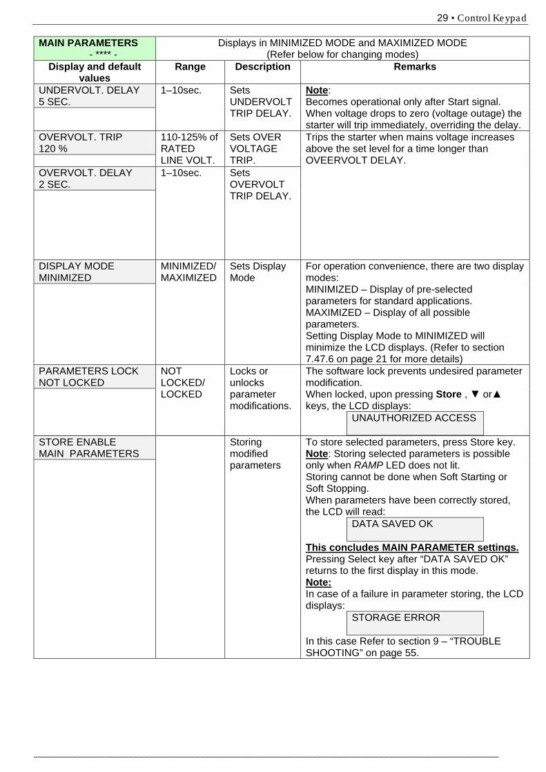
UNDERVOLT. DELAY 5 SEC.
1–10sec. Sets UNDERVOLT TRIP DELAY.
Note: Becomes operational only after Start signal. When voltage drops to zero (voltage outage) the starter will trip immediately, overriding the delay.
OVERVOLT. TRIP 120 %
110-125% of RATED LINE VOLT.
Sets OVER VOLTAGE TRIP.
Trips the starter when mains voltage increases above the set level for a time longer than OVEERVOLT DELAY.
OVERVOLT. DELAY 2 SEC.
1–10sec. Sets OVERVOLT TRIP DELAY.
DISPLAY MODE MINIMIZED
MINIMIZED/ MAXIMIZED
Sets Display Mode
For operation convenience, there are two display modes: MINIMIZED – Display of pre-selected parameters for standard applications. MAXIMIZED – Display of all possible parameters. Setting Display Mode to MINIMIZED will minimize the LCD displays. (Refer to section 7.4 7.6 on page 21 for more details)
PARAMETERS LOCK NOT LOCKED
NOT LOCKED/ LOCKED
Locks or unlocks parameter modifications.
The software lock prevents undesired parameter modification. When locked, upon pressing Store , ▼ or▲ keys, the LCD displays:
UNAUTHORIZED ACCESS
STORE ENABLE MAIN PARAMETERS
Storing modified parameters
To store selected parameters, press Store key. Note: Storing selected parameters is possible only when RAMP LED does not lit. Storing cannot be done when Soft Starting or Soft Stopping. When parameters have been correctly stored, the LCD will read:
DATA SAVED OK
This concludes MAIN PARAMETER settings. Pressing Select key after “DATA SAVED OK” returns to the first display in this mode. Note: In case of a failure in parameter storing, the LCD displays:
STORAGE ERROR
In this case Refer to section 9 – “TROUBLE SHOOTING” on page 55.
30 • Control Keypad
________________________________________________________________________________________
7.6.3.1 Tripping Curves of the Integrated Overload Protection
The RVS-DX allows motor protection according to IEC class 10 or 20 OR according to NEMA class 10, 20, or 30.
NEMA & IEC Class OVERLOAD curves
NEMA Class 10
1
10
100
1000
10000
0 1 2 3 4 5 6 7 8Current [I/FLA]
Tim
e [s
ec.]
IEC Class 10
1
10
100
1000
10000
0 1 2 3 4 5 6 7 8Current [I/FLA]
Tim
e [s
ec.]
NEMA Class 20
1
10
100
1000
10000
100000
0 1 2 3 4 5 6 7 8Current [I/FLA]
Tim
e [s
ec.]
IEC Class 20
1
10
100
1000
10000
100000
0 1 2 3 4 5 6 7 8Current [I/FLA]
Tim
e [s
ec.]
NEMA Class 30
1
10
100
1000
10000
100000
0 1 2 3 4 5 6 7 8Current [I/FLA]
Tim
e [s
ec.]
Cold
Hot
Cold
Hot
Cold
Hot
Cold
Hot
Cold
Hot
31 • Control Keypad
___________________________________________________________________________________________
7.6.4 130BStart Parameters – page 2
START PARAMETERS - **** -
Displays in MINIMIZED MODE and MAXIMIZED MODE (refer to section 7.6.3 on page 27 for changing mode)
Display and default values
Range Description Remarks
SOFT START CURVE 0(STANDARD)
4 (TORQUE) 3 !! 2 !! 1 !! 0 (STANDARD)
Sets starter’s SOFT START CURVE.
Refer to section 7.6.4.1 on page 34. Note: When RVS-DX is connected “Inside-Delta”, only CURVE 0 is applied.
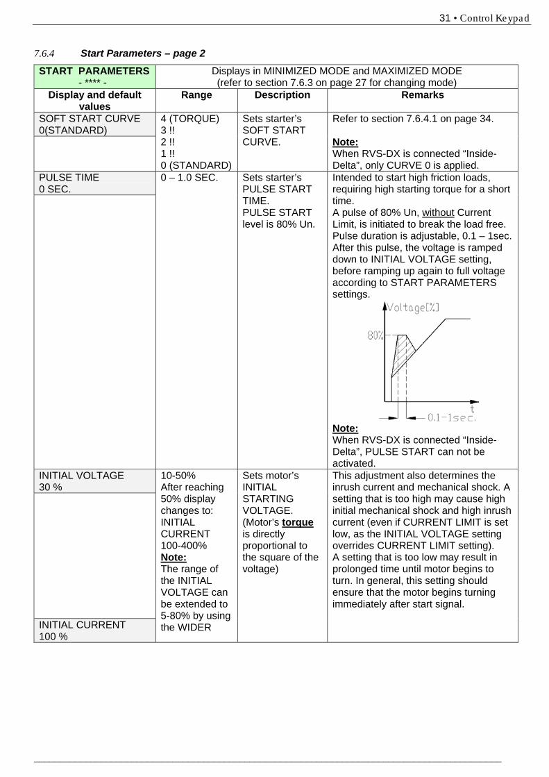
PULSE TIME 0 SEC.
0 – 1.0 SEC. Sets starter’s PULSE START TIME. PULSE START level is 80% Un.
Intended to start high friction loads, requiring high starting torque for a short time. A pulse of 80% Un, without Current Limit, is initiated to break the load free. Pulse duration is adjustable, 0.1 – 1sec. After this pulse, the voltage is ramped down to INITIAL VOLTAGE setting, before ramping up again to full voltage according to START PARAMETERS settings.
Note: When RVS-DX is connected “Inside-Delta”, PULSE START can not be activated.
INITIAL VOLTAGE 30 %
10-50% After reaching 50% display changes to: INITIAL CURRENT 100-400% Note: The range of the INITIAL VOLTAGE can be extended to 5-80% by using the WIDER
Sets motor’s INITIAL STARTING VOLTAGE. (Motor’s torque is directly proportional to the square of the voltage)
This adjustment also determines the inrush current and mechanical shock. A setting that is too high may cause high initial mechanical shock and high inrush current (even if CURRENT LIMIT is set low, as the INITIAL VOLTAGE setting overrides CURRENT LIMIT setting). A setting that is too low may result in prolonged time until motor begins to turn. In general, this setting should ensure that the motor begins turning immediately after start signal.
INITIAL CURRENT 100 %
32 • Control Keypad
________________________________________________________________________________________
START PARAMETERS - **** -
Displays in MINIMIZED MODE and MAXIMIZED MODE (refer to section 7.6.3 on page 27 for changing mode)
SETTING as described in section 7.6.7 page 38.
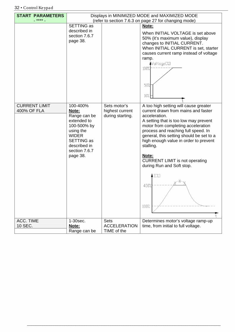
Note: When INITIAL VOLTAGE is set above 50% (it’s maximum value), display changes to INITIAL CURRENT. When INITIAL CURRENT is set, starter causes current ramp instead of voltage ramp.
CURRENT LIMIT 400% OF FLA
100-400% Note: Range can be extended to 100-500% by using the WIDER SETTING as described in section 7.6.7 page 38.
Sets motor’s highest current during starting.
A too high setting will cause greater current drawn from mains and faster acceleration. A setting that is too low may prevent motor from completing acceleration process and reaching full speed. In general, this setting should be set to a high enough value in order to prevent stalling.
Note: CURRENT LIMIT is not operating during Run and Soft stop.
ACC. TIME 10 SEC.
1-30sec. Note: Range can be
Sets ACCELERATION TIME of the
Determines motor’s voltage ramp-up time, from initial to full voltage.
33 • Control Keypad
___________________________________________________________________________________________
START PARAMETERS - **** -
Displays in MINIMIZED MODE and MAXIMIZED MODE (refer to section 7.6.3 on page 27 for changing mode)
extended to 1-90sec. by using the WIDER SETTING as described in section 7.6.7 page 38.
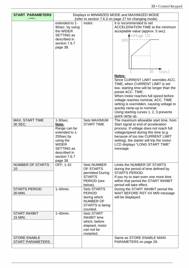
motor. It is recommended to set ACCELERATION TIME to the minimum acceptable value (approx. 5 sec).
Notes: Since CURRENT LIMIT overrides ACC. TIME, when CURRENT LIMIT is set low, starting time will be longer than the preset ACC. TIME. When motor reaches full speed before voltage reaches nominal, ACC. TIME setting is overridden, causing voltage to quickly ramp-up to nominal. Using starting curves 1, 2, 3 prevents quick ramp up.
MAX. START TIME 30 SEC.
1-30sec. Note: Range can be extended to 1-250sec.by using the WIDER SETTING as described in section 7.6.7 page 38.
Sets MAXIMUM START TIME
The maximum allowable start time, from Start signal to end of acceleration process. If voltage does not reach full voltage/speed during this time (e.g. because of too low CURRENT LIMIT setting), the starter will trip the motor. LCD displays “LONG START TIME” message.
NUMBER OF STARTS 10
OFF, 1-10 Sets NUMBER OF STARTS permitted During STARTS PERIOD (see below).
Limits the NUMBER OF STARTS during the period of time defined by STARTS PERIOD. If you try to start even one more time within that period the START INHIBIT period will take effect.
STARTS PERIOD 30 MIN.
1–60min. Sets STARTS PERIOD during which NUMBER OF STARTS is being counted.
During the START INHIBIT period the WAIT BEFORE RST XX MIN message will be displayed.
START INHIBIT 15 MIN.
1–60min. Sets START INHIBIT time which, before elapsed, motor can not be restarted.
STORE ENABLE START PARAMETERS
Same as STORE ENABLE MAIN PARAMETERS on page 29.
34 • Control Keypad
________________________________________________________________________________________
7.6.4.1 Soft start parameters
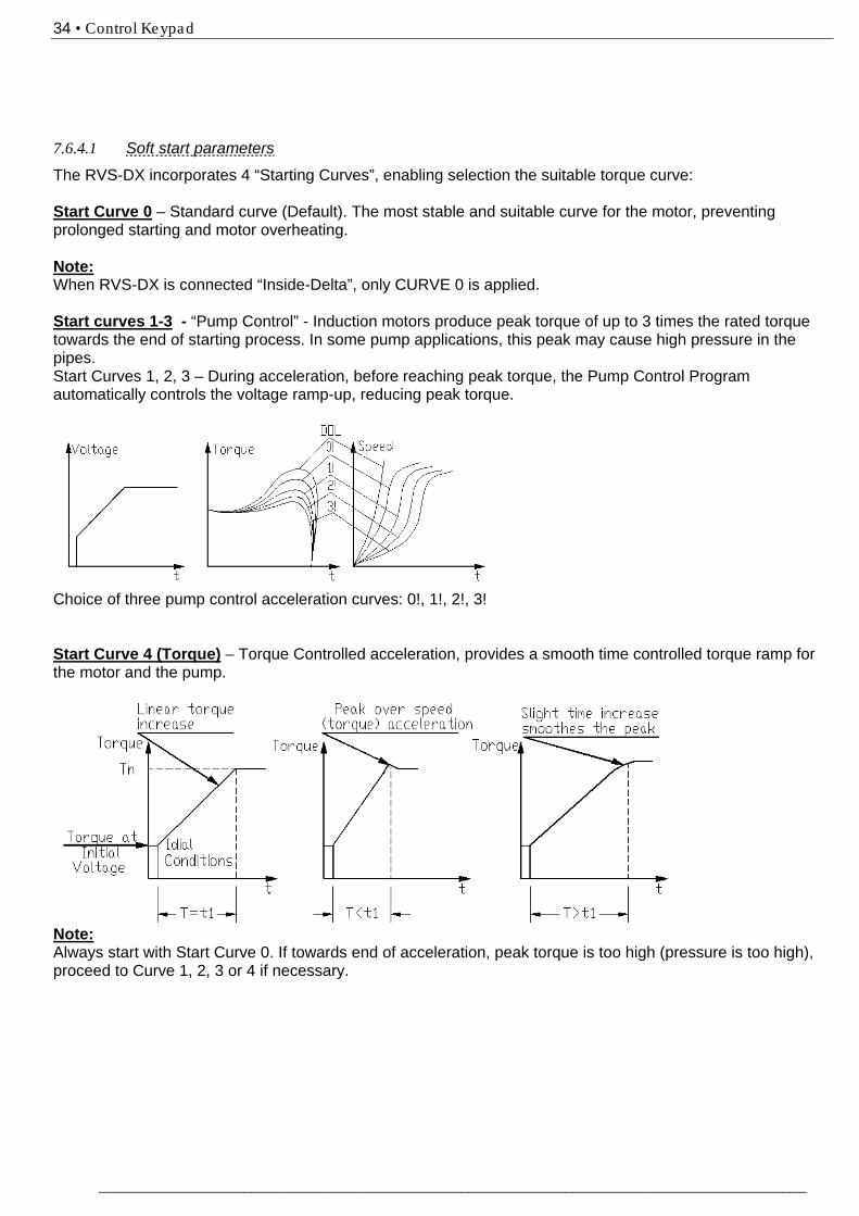
The RVS-DX incorporates 4 “Starting Curves”, enabling selection the suitable torque curve: Start Curve 0 – Standard curve (Default). The most stable and suitable curve for the motor, preventing prolonged starting and motor overheating. Note: When RVS-DX is connected “Inside-Delta”, only CURVE 0 is applied. Start curves 1-3 - “Pump Control” - Induction motors produce peak torque of up to 3 times the rated torque towards the end of starting process. In some pump applications, this peak may cause high pressure in the pipes. Start Curves 1, 2, 3 – During acceleration, before reaching peak torque, the Pump Control Program automatically controls the voltage ramp-up, reducing peak torque.
Choice of three pump control acceleration curves: 0!, 1!, 2!, 3! Start Curve 4 (Torque) – Torque Controlled acceleration, provides a smooth time controlled torque ramp for the motor and the pump.
Note: Always start with Start Curve 0. If towards end of acceleration, peak torque is too high (pressure is too high), proceed to Curve 1, 2, 3 or 4 if necessary.

35 • Control Keypad
___________________________________________________________________________________________
7.6.5 Stop Parameters – page 3
STOP PARAMETERS - **** -
Displays in MINIMIZED MODE and MAXIMIZED MODE (refer to section 7.6.3 on page 27 for changing mode)
Display and default values
Range Description Remarks
SOFT STOP CURVE 0(STANDARD)
4 (TORQUE) 3 !! 2 !! 1 !! 0 (STANDARD)
Sets starter’s SOFT STOP CURVE.
Refer to section 7.6.5.1 on page 35
DEC. TIME 0 SEC.
0 – 30sec. Note: Range can be extended to 90sec. by using the WIDER SETTING as described in section 7.6.7 page 38.
Sets DECELERATION TIME of the motor.
Used for controlled deceleration of high friction loads. Determines motor’s voltage ramp down time.
FINAL TORQUE 0 (MIN.)
0 (min.) – 10 (max.)
Sets FINAL TORQUE during Soft Stop.
Determines torque towards end of SOFT STOP. If current is still flowing after speed is softly reduced to zero, increase FINAL TORQUE setting.
STORE ENABLE STOP PARAMETERS
Same as STORE ENABLE MAIN PARAMETERS on page 29.
7.6.5.1 Soft stop parameters
The RVS-DX incorporates 4 “Starting Curves”, enabling selection the suitable torque curve: Stop Curve 0 – Standard curve (Default) – voltage is linearly reduced from nominal to zero. The most stable and suitable curve for the motor, preventing prolonged stopping and motor overheating. Stop curves 1, 2, 3 Pump Control – In some pump applications, when pumping to a higher level, a considerable part of the torque is constant and does not decrease with speed. It may happen that during deceleration process, when voltage is decreasing, motor torque quickly falls below load torque abruptly (instead of smoothly decreasing speed to zero) closing the valve and causing Water Hammer. Curves 1, 2 and 3 are intended to prevent Water Hammer phenomenon. In pump applications, load torque decreases in square relation to the speed, thus correct control of voltage reduction reduces torque adequately to smoothly decelerate to a stop. Note:

36 • Control Keypad
________________________________________________________________________________________
It is recommended that for all standard applications (not pumps), Stop Curve 0 will be used. To reduce Water Hammer select STOP CURVE 1, than 2 or 3, if necessary.
Curve 4 - Torque Curve - Provides linear deceleration of the torque. In certain loads, linear torque deceleration can result in close to linear speed deceleration. The RVS-DX Torque Control does not require any external torque or speed sensor (tacho-gen. etc.).
37 • Control Keypad
___________________________________________________________________________________________
7.6.6 Dual Adjustment Parameters – page 4
DUAL ADJUSTMENT PARAMETERS
Displays in MAXIMIZED MODE only (refer to section 7.6.3 on page 27 for changing mode)
Display and default values
Description Remarks
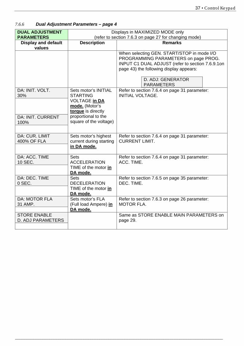
When selecting GEN. START/STOP in mode I/O PROGRAMMING PARAMETERS on page PROG. INPUT C1 DUAL ADJUST (refer to section 7.6.9.1on page 43) the following display appears:
D. ADJ: GENERATOR PARAMETERS
DA: INIT. VOLT. 30%
Sets motor’s INITIAL STARTING VOLTAGE in DA mode. (Motor’s torque is directly proportional to the square of the voltage)
Refer to section 7.6.4 on page 31 parameter: INITIAL VOLTAGE.
DA: INIT. CURRENT 100%
DA: CUR. LIMIT 400% OF FLA
Sets motor’s highest current during starting in DA mode.
Refer to section 7.6.4 on page 31 parameter: CURRENT LIMIT.
DA: ACC. TIME 10 SEC.
Sets ACCELERATION TIME of the motor in DA mode.
Refer to section 7.6.4 on page 31 parameter: ACC. TIME.
DA: DEC. TIME 0 SEC.
Sets DECELERATION TIME of the motor in DA mode.
Refer to section 7.6.5 on page 35 parameter: DEC. TIME.
DA: MOTOR FLA 31 AMP.
Sets motor’s FLA (Full load Ampere) in DA mode.
Refer to section 7.6.3 on page 26 parameter: MOTOR FLA.
STORE ENABLE D. ADJ PARAMETERS
Same as STORE ENABLE MAIN PARAMETERS on page 29.
38 • Control Keypad
________________________________________________________________________________________
7.6.7 Special features Parameters – page 5
SPECIAL FEATURES PARAMETERS
Displays in MAXIMIZED MODE only (refer to section 7.6.3 on page 27 for changing mode)
Display and default values
Range Description Remarks
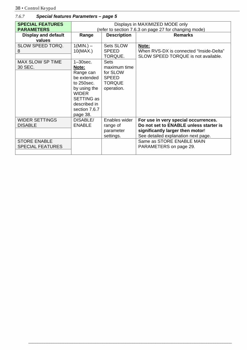
SLOW SPEED TORQ. 8
1(MIN.) – 10(MAX.)
Sets SLOW SPEED TORQUE.
Note: When RVS-DX is connected “Inside-Delta” SLOW SPEED TORQUE is not available.
MAX SLOW SP TIME 30 SEC.
1–30sec. Note: Range can be extended to 250sec. by using the WIDER SETTING as described in section 7.6.7 page 38.
Sets maximum time for SLOW SPEED TORQUE operation.
WIDER SETTINGS DISABLE
DISABLE/ ENABLE
Enables wider range of parameter settings.
For use in very special occurrences. Do not set to ENABLE unless starter is significantly larger then motor! See detailed explanation next page.
STORE ENABLE SPECIAL FEATURES
Same as STORE ENABLE MAIN PARAMETERS on page 29.
39 • Control Keypad
___________________________________________________________________________________________
7.6.7.1 WIDER SETTINGS Parameters:
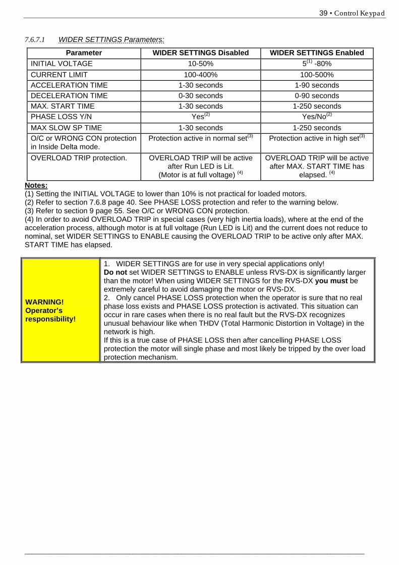
Parameter WIDER SETTINGS Disabled WIDER SETTINGS Enabled INITIAL VOLTAGE 10-50% 5(1) -80% CURRENT LIMIT 100-400% 100-500% ACCELERATION TIME 1-30 seconds 1-90 seconds DECELERATION TIME 0-30 seconds 0-90 seconds MAX. START TIME 1-30 seconds 1-250 seconds PHASE LOSS Y/N Yes(2) Yes/No(2) MAX SLOW SP TIME 1-30 seconds 1-250 seconds O/C or WRONG CON protection in Inside Delta mode.
Protection active in normal set(3) Protection active in high set(3)
OVERLOAD TRIP protection. OVERLOAD TRIP will be active after Run LED is Lit.
(Motor is at full voltage) (4)
OVERLOAD TRIP will be active after MAX. START TIME has
elapsed. (4) Notes: (1) Setting the INITIAL VOLTAGE to lower than 10% is not practical for loaded motors. (2) Refer to section 7.6.8 page 40. See PHASE LOSS protection and refer to the warning below. (3) Refer to section 9 page 55. See O/C or WRONG CON protection. (4) In order to avoid OVERLOAD TRIP in special cases (very high inertia loads), where at the end of the acceleration process, although motor is at full voltage (Run LED is Lit) and the current does not reduce to nominal, set WIDER SETTINGS to ENABLE causing the OVERLOAD TRIP to be active only after MAX. START TIME has elapsed.
WARNING! Operator’s responsibility!
1. WIDER SETTINGS are for use in very special applications only! Do not set WIDER SETTINGS to ENABLE unless RVS-DX is significantly larger than the motor! When using WIDER SETTINGS for the RVS-DX you must be extremely careful to avoid damaging the motor or RVS-DX. 2. Only cancel PHASE LOSS protection when the operator is sure that no real phase loss exists and PHASE LOSS protection is activated. This situation can occur in rare cases when there is no real fault but the RVS-DX recognizes unusual behaviour like when THDV (Total Harmonic Distortion in Voltage) in the network is high. If this is a true case of PHASE LOSS then after cancelling PHASE LOSS protection the motor will single phase and most likely be tripped by the over load protection mechanism.
40 • Control Keypad
________________________________________________________________________________________
7.6.8 Fault Parameters – page 6
FAULT PARAMETERS - **** -
Displays in MAXIMIZED MODE only (refer to section 7.6.3 on page 27 for changing mode)
Display and default values
Range Description Remarks
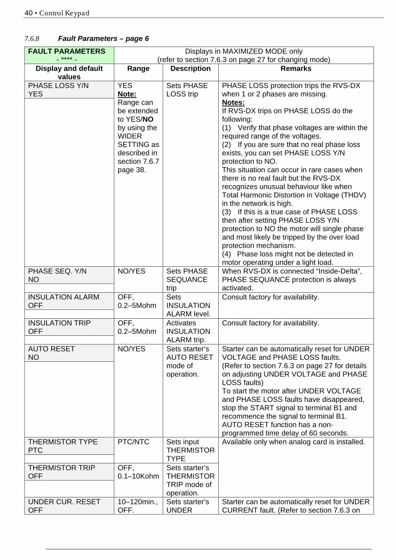
PHASE LOSS Y/N YES
YES Note: Range can be extended to YES/NO by using the WIDER SETTING as described in section 7.6.7 page 38.
Sets PHASE LOSS trip
PHASE LOSS protection trips the RVS-DX when 1 or 2 phases are missing. Notes: If RVS-DX trips on PHASE LOSS do the following: (1) Verify that phase voltages are within the required range of the voltages. (2) If you are sure that no real phase loss exists, you can set PHASE LOSS Y/N protection to NO. This situation can occur in rare cases when there is no real fault but the RVS-DX recognizes unusual behaviour like when Total Harmonic Distortion in Voltage (THDV) in the network is high. (3) If this is a true case of PHASE LOSS then after setting PHASE LOSS Y/N protection to NO the motor will single phase and most likely be tripped by the over load protection mechanism. (4) Phase loss might not be detected in motor operating under a light load.
PHASE SEQ. Y/N NO
NO/YES Sets PHASE SEQUANCE trip
When RVS-DX is connected “Inside-Delta”, PHASE SEQUANCE protection is always activated.
INSULATION ALARM OFF
OFF, 0.2–5Mohm
Sets INSULATION ALARM level.
Consult factory for availability.
INSULATION TRIP OFF
OFF, 0.2–5Mohm
Activates INSULATION ALARM trip.
Consult factory for availability.
AUTO RESET NO
NO/YES Sets starter’s AUTO RESET mode of operation.
Starter can be automatically reset for UNDER VOLTAGE and PHASE LOSS faults. (Refer to section 7.6.3 on page 27 for details on adjusting UNDER VOLTAGE and PHASE LOSS faults) To start the motor after UNDER VOLTAGE and PHASE LOSS faults have disappeared, stop the START signal to terminal B1 and recommence the signal to terminal B1. AUTO RESET function has a non-programmed time delay of 60 seconds.
THERMISTOR TYPE PTC
PTC/NTC Sets input THERMISTOR TYPE
Available only when analog card is installed.
THERMISTOR TRIP OFF
OFF, 0.1–10Kohm
Sets starter’s THERMISTOR TRIP mode of operation.
UNDER CUR. RESET OFF
10–120min., OFF.
Sets starter’s UNDER
Starter can be automatically reset for UNDER CURRENT fault. (Refer to section 7.6.3 on
41 • Control Keypad
___________________________________________________________________________________________
FAULT PARAMETERS - **** -
Displays in MAXIMIZED MODE only (refer to section 7.6.3 on page 27 for changing mode)
Display and default values
Range Description Remarks
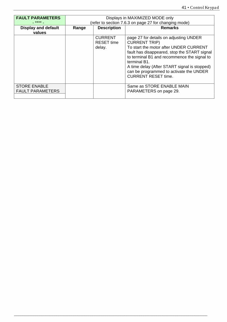
CURRENT RESET time delay.
page 27 for details on adjusting UNDER CURRENT TRIP) To start the motor after UNDER CURRENT fault has disappeared, stop the START signal to terminal B1 and recommence the signal to terminal B1. A time delay (After START signal is stopped) can be programmed to activate the UNDER CURRENT RESET time.
STORE ENABLE FAULT PARAMETERS
Same as STORE ENABLE MAIN PARAMETERS on page 29.

42 • Control Keypad
________________________________________________________________________________________
7.6.9 135BI/O Programming Parameters – page 7
I/O PROGRAMMING PARAMETERS
Displays in MAXIMIZED MODE only (refer to section 7.6.3 on page 27 for changing mode)
Display and default values
Range Description Remarks
PROG. INPUT C1 REMOTE RESET
START/STOP; REMOTE RESET; EXTERNAL FAULT; SLOW SPD/REVERSE; GEN. START/STOP; DUAL ADJUSTMENT;
Sets TERMINAL C1 function
Refer to section 7.6.9.1 on page 43.
FAULT RELAY TYPE FAULT
FAULT, FAULT – FAIL SAFE
Sets FAULT RELAY mode of operation.
When configured to FAULT the internal relay is energized upon fault. When configured to FAULT-FAIL SAFE the relay is de-energized upon fault. In this mode, while normal operation, the fault relay is energized. Relay will also de-energize upon control power outage.
PROG. AUX. RELAY IMMEDIATE
IMMEDIATE/ END OF ACCEL.
Sets starter’s AUX. RELAY mode of operation.
When configured to IMMEDIATE – the AUX. RELAY closes its contact at start signal (after programmed “on delay” time has elapsed) and open its contact at the end of deceleration time (if any) (after programmed “off delay” time has elapsed). When configured to END OF ACCEL. -the AUX. RELAY closes its contact at end of soft start (after programmed “on delay” time has elapsed) and open its contact at the beginning of soft stop (if any) (after programmed “off delay” time has elapsed).
RELAY ON DELAY 0 SEC.
0–60sec. Sets starter’s AUX. RELAY on delay time.
RELAY OFF DELAY 0 SEC.
0–60sec. Sets starter’s AUX. RELAY off delay time
AN. OUT PARAMETER I, 0...200% OF FLA
I, 0...200% OF FLA P, 0...200% OF Pn POWER FACTOR
Sets ANALOG OUTPUT mode of operation.
Available only when analog card is installed. When analog card is installed, full scale of the readings (20mA or 10V as per dip-switches settings) are related to 200%FLA. (2x rated motor current) or 200% of rated power or POWER FACTOR. Note: POWER FACTOR & POWER measurement only available in RVS-DX58A and up.
STORE ENABLE I/O PROG. PARAM.
Same as STORE ENABLE MAIN PARAMETERS on page 29.
43 • Control Keypad
___________________________________________________________________________________________
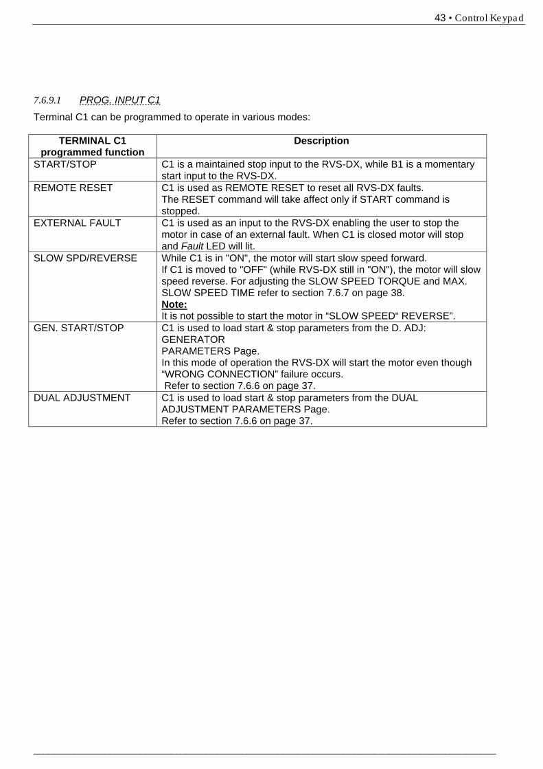
7.6.9.1 PROG. INPUT C1
Terminal C1 can be programmed to operate in various modes:
TERMINAL C1 programmed function
Description
START/STOP C1 is a maintained stop input to the RVS-DX, while B1 is a momentary start input to the RVS-DX.
REMOTE RESET C1 is used as REMOTE RESET to reset all RVS-DX faults. The RESET command will take affect only if START command is stopped.
EXTERNAL FAULT C1 is used as an input to the RVS-DX enabling the user to stop the motor in case of an external fault. When C1 is closed motor will stop and Fault LED will lit.
SLOW SPD/REVERSE While C1 is in "ON", the motor will start slow speed forward. If C1 is moved to "OFF" (while RVS-DX still in "ON"), the motor will slow speed reverse. For adjusting the SLOW SPEED TORQUE and MAX. SLOW SPEED TIME refer to section 7.6.7 on page 38. Note: It is not possible to start the motor in “SLOW SPEED“ REVERSE”.
GEN. START/STOP C1 is used to load start & stop parameters from the D. ADJ: GENERATOR PARAMETERS Page. In this mode of operation the RVS-DX will start the motor even though “WRONG CONNECTION” failure occurs. Refer to section 7.6.6 on page 37.
DUAL ADJUSTMENT C1 is used to load start & stop parameters from the DUAL ADJUSTMENT PARAMETERS Page. Refer to section 7.6.6 on page 37.
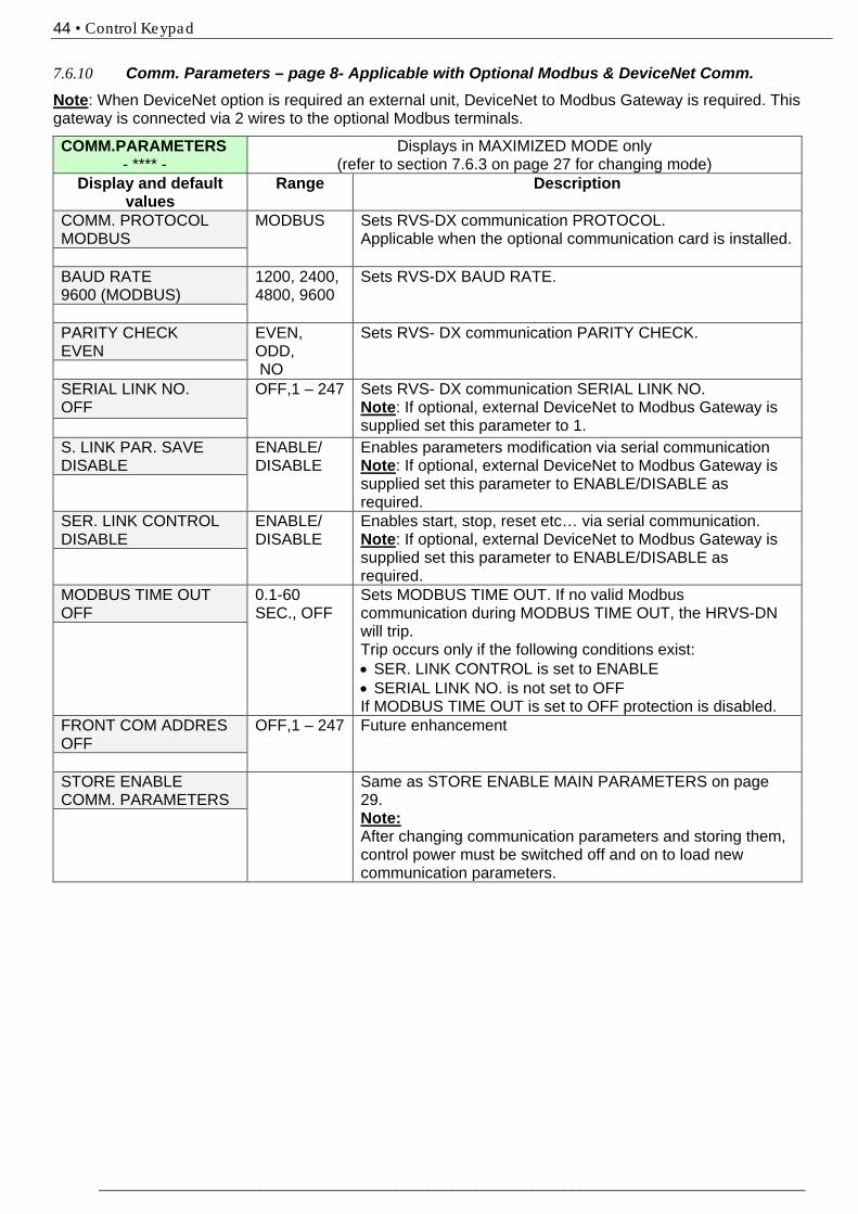
44 • Control Keypad
________________________________________________________________________________________
7.6.10 136BComm. Parameters – page 8- Applicable with Optional Modbus & DeviceNet Comm. 53BNote: When DeviceNet option is required an external unit, DeviceNet to Modbus Gateway is required. This gateway is connected via 2 wires to the optional Modbus terminals.
COMM.PARAMETERS - **** -
Displays in MAXIMIZED MODE only (refer to section 7.6.3 on page 27 for changing mode)
Display and default values
Range Description
COMM. PROTOCOL MODBUS
MODBUS
Sets RVS-DX communication PROTOCOL. Applicable when the optional communication card is installed.
BAUD RATE 9600 (MODBUS)
1200, 2400, 4800, 9600
Sets RVS-DX BAUD RATE.
PARITY CHECK EVEN
EVEN, ODD, NO
Sets RVS- DX communication PARITY CHECK.
SERIAL LINK NO. OFF
OFF,1 – 247 Sets RVS- DX communication SERIAL LINK NO. Note: If optional, external DeviceNet to Modbus Gateway is supplied set this parameter to 1.
S. LINK PAR. SAVE DISABLE
ENABLE/ DISABLE
Enables parameters modification via serial communication Note: If optional, external DeviceNet to Modbus Gateway is supplied set this parameter to ENABLE/DISABLE as required.
SER. LINK CONTROL DISABLE
ENABLE/ DISABLE
Enables start, stop, reset etc… via serial communication. Note: If optional, external DeviceNet to Modbus Gateway is supplied set this parameter to ENABLE/DISABLE as required.
MODBUS TIME OUT OFF
0.1-60 SEC., OFF
Sets MODBUS TIME OUT. If no valid Modbus communication during MODBUS TIME OUT, the HRVS-DN will trip. Trip occurs only if the following conditions exist: • SER. LINK CONTROL is set to ENABLE • SERIAL LINK NO. is not set to OFF If MODBUS TIME OUT is set to OFF protection is disabled.
FRONT COM ADDRES OFF
OFF,1 – 247 Future enhancement
STORE ENABLE COMM. PARAMETERS
Same as STORE ENABLE MAIN PARAMETERS on page 29. Note: After changing communication parameters and storing them, control power must be switched off and on to load new communication parameters.
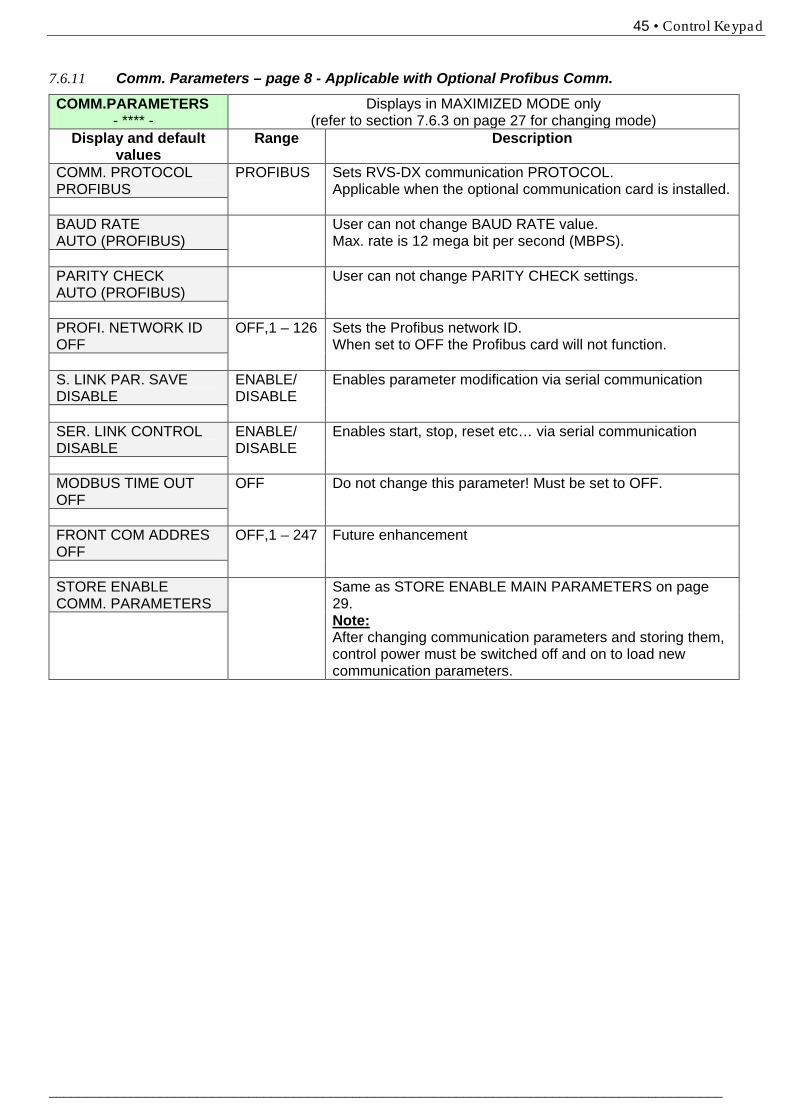
45 • Control Keypad
___________________________________________________________________________________________
7.6.11 Comm. Parameters – page 8 - Applicable with Optional Profibus Comm.
COMM.PARAMETERS - **** -
Displays in MAXIMIZED MODE only (refer to section 7.6.3 on page 27 for changing mode)
Display and default values
Range Description
COMM. PROTOCOL PROFIBUS
PROFIBUS
Sets RVS-DX communication PROTOCOL. Applicable when the optional communication card is installed.
BAUD RATE AUTO (PROFIBUS)
User can not change BAUD RATE value. Max. rate is 12 mega bit per second (MBPS).
PARITY CHECK AUTO (PROFIBUS)
User can not change PARITY CHECK settings.
PROFI. NETWORK ID OFF
OFF,1 – 126 Sets the Profibus network ID. When set to OFF the Profibus card will not function.
S. LINK PAR. SAVE DISABLE
ENABLE/ DISABLE
Enables parameter modification via serial communication
SER. LINK CONTROL DISABLE
ENABLE/ DISABLE
Enables start, stop, reset etc… via serial communication
MODBUS TIME OUT OFF
OFF Do not change this parameter! Must be set to OFF.
FRONT COM ADDRES OFF
OFF,1 – 247 Future enhancement
STORE ENABLE COMM. PARAMETERS
Same as STORE ENABLE MAIN PARAMETERS on page 29. Note: After changing communication parameters and storing them, control power must be switched off and on to load new communication parameters.
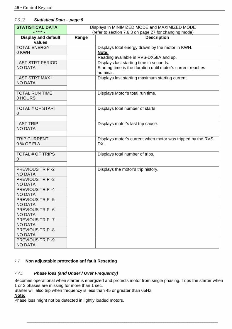
46 • Control Keypad
________________________________________________________________________________________
7.6.12 138BStatistical Data – page 9
STATISTICAL DATA - **** -
Displays in MINIMIZED MODE and MAXIMIZED MODE (refer to section 7.6.3 on page 27 for changing mode)
Display and default values
Range Description
TOTAL ENERGY 0 KWH
Displays total energy drawn by the motor in KWH. Note: Reading available in RVS-DX58A and up.
LAST STRT PERIOD NO DATA
Displays last starting time in seconds. Starting time is the duration until motor’s current reaches nominal.
LAST STRT MAX I NO DATA
Displays last starting maximum starting current.
TOTAL RUN TIME 0 HOURS
Displays Motor’s total run time.
TOTAL # OF START 0
Displays total number of starts.
LAST TRIP NO DATA
Displays motor’s last trip cause.
TRIP CURRENT 0 % OF FLA
Displays motor’s current when motor was tripped by the RVS-DX.
TOTAL # OF TRIPS 0
Displays total number of trips.
PREVIOUS TRIP -2 NO DATA
Displays the motor’s trip history.
PREVIOUS TRIP -3 NO DATA PREVIOUS TRIP -4 NO DATA PREVIOUS TRIP -5 NO DATA PREVIOUS TRIP -6 NO DATA PREVIOUS TRIP -7 NO DATA PREVIOUS TRIP -8 NO DATA PREVIOUS TRIP -9 NO DATA
7.7 98BNon adjustable protection anf fault Resetting 7.7.1 139BPhase loss (and Under / Over Frequency) Becomes operational when starter is energized and protects motor from single phasing. Trips the starter when 1 or 2 phases are missing for more than 1 sec. Starter will also trip when frequency is less than 45 or greater than 65Hz. Note: Phase loss might not be detected in lightly loaded motors.
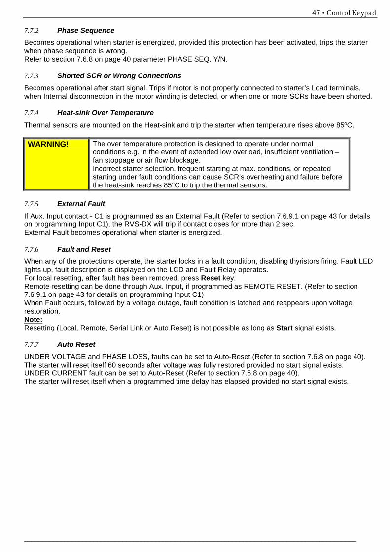
47 • Control Keypad
___________________________________________________________________________________________
7.7.2 Phase Sequence Becomes operational when starter is energized, provided this protection has been activated, trips the starter when phase sequence is wrong. Refer to section 7.6.8 on page 40 parameter PHASE SEQ. Y/N. 7.7.3 Shorted SCR or Wrong Connections Becomes operational after start signal. Trips if motor is not properly connected to starter’s Load terminals, when Internal disconnection in the motor winding is detected, or when one or more SCRs have been shorted. 7.7.4 Heat-sink Over Temperature Thermal sensors are mounted on the Heat-sink and trip the starter when temperature rises above 85ºC. WARNING! The over temperature protection is designed to operate under normal
conditions e.g. in the event of extended low overload, insufficient ventilation – fan stoppage or air flow blockage. Incorrect starter selection, frequent starting at max. conditions, or repeated starting under fault conditions can cause SCR’s overheating and failure before the heat-sink reaches 85°C to trip the thermal sensors.
7.7.5 External Fault If Aux. Input contact - C1 is programmed as an External Fault (Refer to section 7.6.9.1 on page 43 for details on programming Input C1), the RVS-DX will trip if contact closes for more than 2 sec. External Fault becomes operational when starter is energized. 7.7.6 Fault and Reset When any of the protections operate, the starter locks in a fault condition, disabling thyristors firing. Fault LED lights up, fault description is displayed on the LCD and Fault Relay operates. For local resetting, after fault has been removed, press Reset key. Remote resetting can be done through Aux. Input, if programmed as REMOTE RESET. (Refer to section 7.6.9.1 on page 43 for details on programming Input C1) When Fault occurs, followed by a voltage outage, fault condition is latched and reappears upon voltage restoration. Note: Resetting (Local, Remote, Serial Link or Auto Reset) is not possible as long as Start signal exists. 7.7.7 Auto Reset UNDER VOLTAGE and PHASE LOSS, faults can be set to Auto-Reset (Refer to section 7.6.8 on page 40). The starter will reset itself 60 seconds after voltage was fully restored provided no start signal exists. UNDER CURRENT fault can be set to Auto-Reset (Refer to section 7.6.8 on page 40). The starter will reset itself when a programmed time delay has elapsed provided no start signal exists.
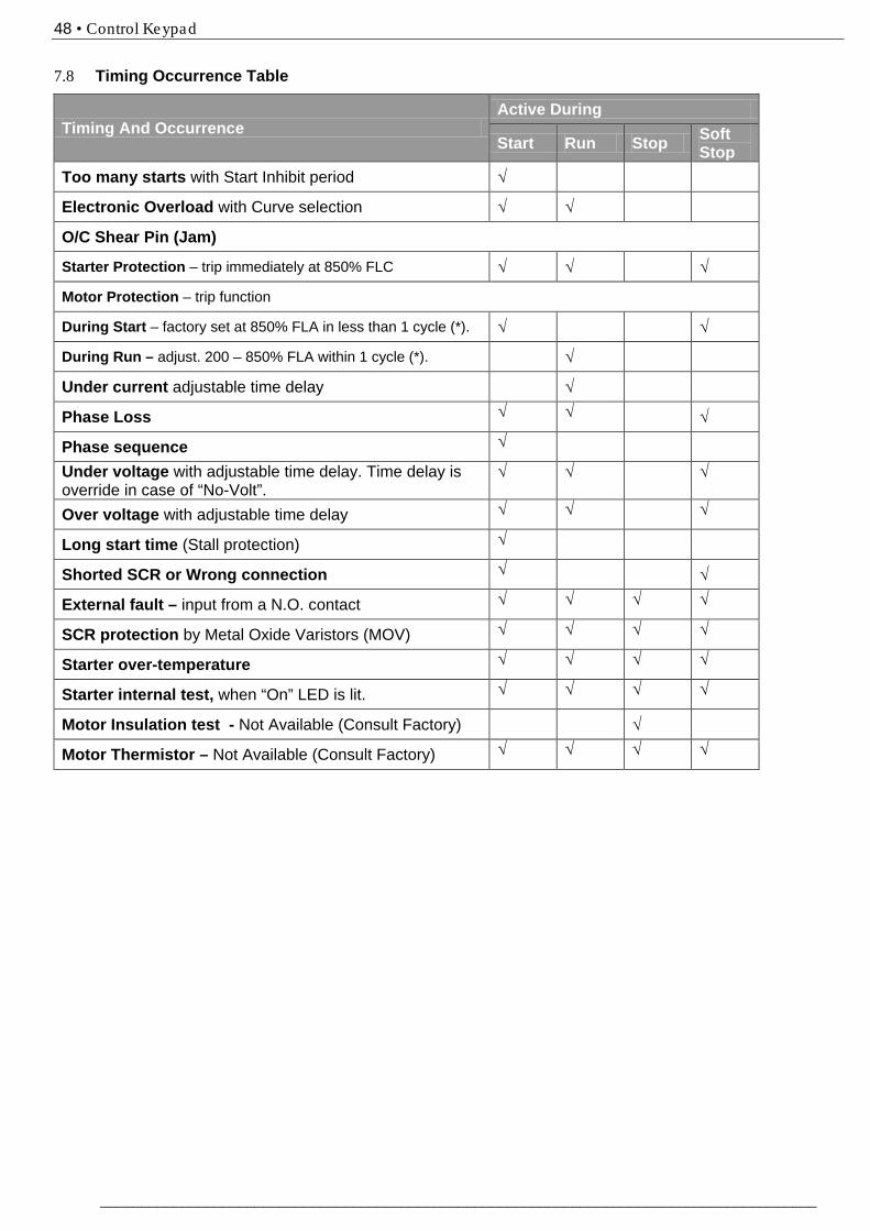
48 • Control Keypad
________________________________________________________________________________________
7.8 Timing Occurrence Table
Timing And Occurrence Active During
Start Run Stop Soft Stop
Too many starts with Start Inhibit period √
Electronic Overload with Curve selection √ √
O/C Shear Pin (Jam)
Starter Protection – trip immediately at 850% FLC √ √ √
Motor Protection – trip function
During Start – factory set at 850% FLA in less than 1 cycle (*). √ √
During Run – adjust. 200 – 850% FLA within 1 cycle (*). √
Under current adjustable time delay √
Phase Loss √ √ √
Phase sequence √
Under voltage with adjustable time delay. Time delay is override in case of “No-Volt”.
√ √ √
Over voltage with adjustable time delay √ √ √
Long start time (Stall protection) √
Shorted SCR or Wrong connection √ √
External fault – input from a N.O. contact √ √ √ √
SCR protection by Metal Oxide Varistors (MOV) √ √ √ √
Starter over-temperature √ √ √ √
Starter internal test, when “On” LED is lit. √ √ √ √
Motor Insulation test - Not Available (Consult Factory) √
Motor Thermistor – Not Available (Consult Factory) √ √ √ √
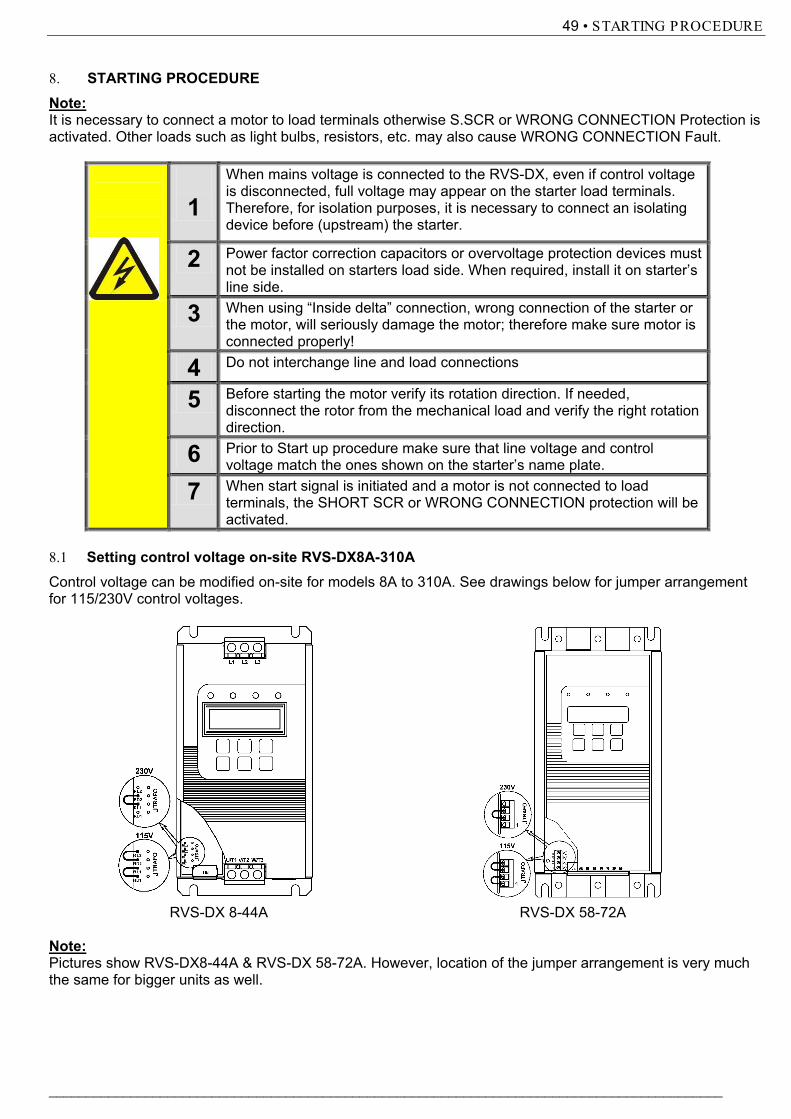
49 • STARTING PROCEDURE
___________________________________________________________________________________________
8. STARTING PROCEDURENote:It is necessary to connect a motor to load terminals otherwise S.SCR or WRONG CONNECTION Protection is activated. Other loads such as light bulbs, resistors, etc. may also cause WRONG CONNECTION Fault.
1When mains voltage is connected to the RVS-DX, even if control voltage is disconnected, full voltage may appear on the starter load terminals. Therefore, for isolation purposes, it is necessary to connect an isolating device before (upstream) the starter.
2 Power factor correction capacitors or overvoltage protection devices must not be installed on starters load side. When required, install it on starter’s line side.
3 When using “Inside delta” connection, wrong connection of the starter or the motor, will seriously damage the motor; therefore make sure motor is connected properly!
4 Do not interchange line and load connections
5 Before starting the motor verify its rotation direction. If needed, disconnect the rotor from the mechanical load and verify the right rotation direction.
6 Prior to Start up procedure make sure that line voltage and control voltage match the ones shown on the starter’s name plate.
7 When start signal is initiated and a motor is not connected to load terminals, the SHORT SCR or WRONG CONNECTION protection will be activated.
8.1 Setting control voltage on-site RVS-DX8A-310AControl voltage can be modified on-site for models 8A to 310A. See drawings below for jumper arrangement for 115/230V control voltages.
RVS-DX 8-44A RVS-DX 58-72A
Note:Pictures show RVS-DX8-44A & RVS-DX 58-72A. However, location of the jumper arrangement is very much the same for bigger units as well.
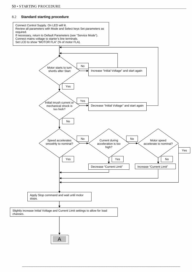
50 • STARTING PROCEDURE
________________________________________________________________________________________
8.2 Standard starting procedure
Connect Control Supply. On LED will lit. Review all parameters with Mode and Select keys Set parameters as required. If necessary, return to Default Parameters (see “Service Mode”). Connect mains voltage to starter’s line terminals. Set LCD to show “MOTOR FLA” (% of motor FLA).
A l S d
Motor starts to turn shortly after Start
Initial inrush current or mechanical shock is
too high?
Increase “Initial Voltage” and start again
Decrease “Initial Voltage” and start again
Speed accelerates smoothly to nominal?
Apply Stop command and wait until motor stops.
Slightly increase Initial Voltage and Current Limit settings to allow for load changes.
Current during acceleration is too
high?
Decrease “Current Limit”
Motor speed accelerate to nominal?
Increase “Current Limit”
Yes
No
Yes
No
No
Yes Yes
No
No
Yes
A
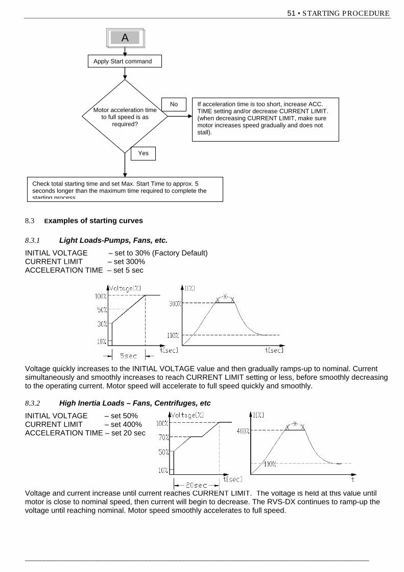
51 • STARTING PROCEDURE
___________________________________________________________________________________________
8.3 102BExamples of starting curves
8.3.1 146BLight Loads-Pumps, Fans, etc. INITIAL VOLTAGE – set to 30% (Factory Default) CURRENT LIMIT – set 300% ACCELERATION TIME – set 5 sec Voltage quickly increases to the INITIAL VOLTAGE value and then gradually ramps-up to nominal. Current simultaneously and smoothly increases to reach CURRENT LIMIT setting or less, before smoothly decreasing to the operating current. Motor speed will accelerate to full speed quickly and smoothly. 8.3.2 147BHigh Inertia Loads – Fans, Centrifuges, etc INITIAL VOLTAGE – set 50% CURRENT LIMIT – set 400% ACCELERATION TIME – set 20 sec Voltage and current increase until current reaches CURRENT LIMIT. The voltage is held at this value until motor is close to nominal speed, then current will begin to decrease. The RVS-DX continues to ramp-up the voltage until reaching nominal. Motor speed smoothly accelerates to full speed.
Check total starting time and set Max. Start Time to approx. 5 seconds longer than the maximum time required to complete the starting process
Motor acceleration time to full speed is as
required?
No
Yes
Apply Start command
If acceleration time is too short, increase ACC. TIME setting and/or decrease CURRENT LIMIT. (when decreasing CURRENT LIMIT, make sure motor increases speed gradually and does not stall).
A
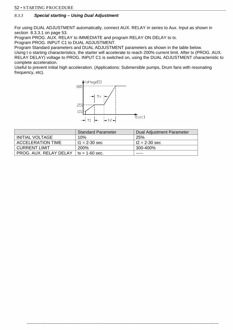
52 • STARTING PROCEDURE
________________________________________________________________________________________
8.3.3 Special starting – Using Dual Adjustment For using DUAL ADJUSTMENT automatically, connect AUX. RELAY in series to Aux. Input as shown in section 8.3.3.1 on page 53. Program PROG. AUX. RELAY to IMMEDIATE and program RELAY ON DELAY to tx. Program PROG. INPUT C1 to DUAL ADJUSTMENT. Program Standard parameters and DUAL ADJUSTMENT parameters as shown in the table below. Using t o starting characteristics, the starter will accelerate to reach 200% current limit. After tx (PROG. AUX. RELAY DELAY) voltage to PROG. INPUT C1 is switched on, using the DUAL ADJUSTMENT characteristic to complete acceleration. Useful to prevent initial high acceleration. (Applications: Submersible pumps, Drum fans with resonating frequency, etc). Standard Parameter Dual Adjustment Parameter INITIAL VOLTAGE 10% 25% ACCELERATION TIME t1 = 2-30 sec t2 = 2-30 sec CURRENT LIMIT 200% 300-400% PROG. AUX. RELAY DELAY tx = 1-60 sec. -----
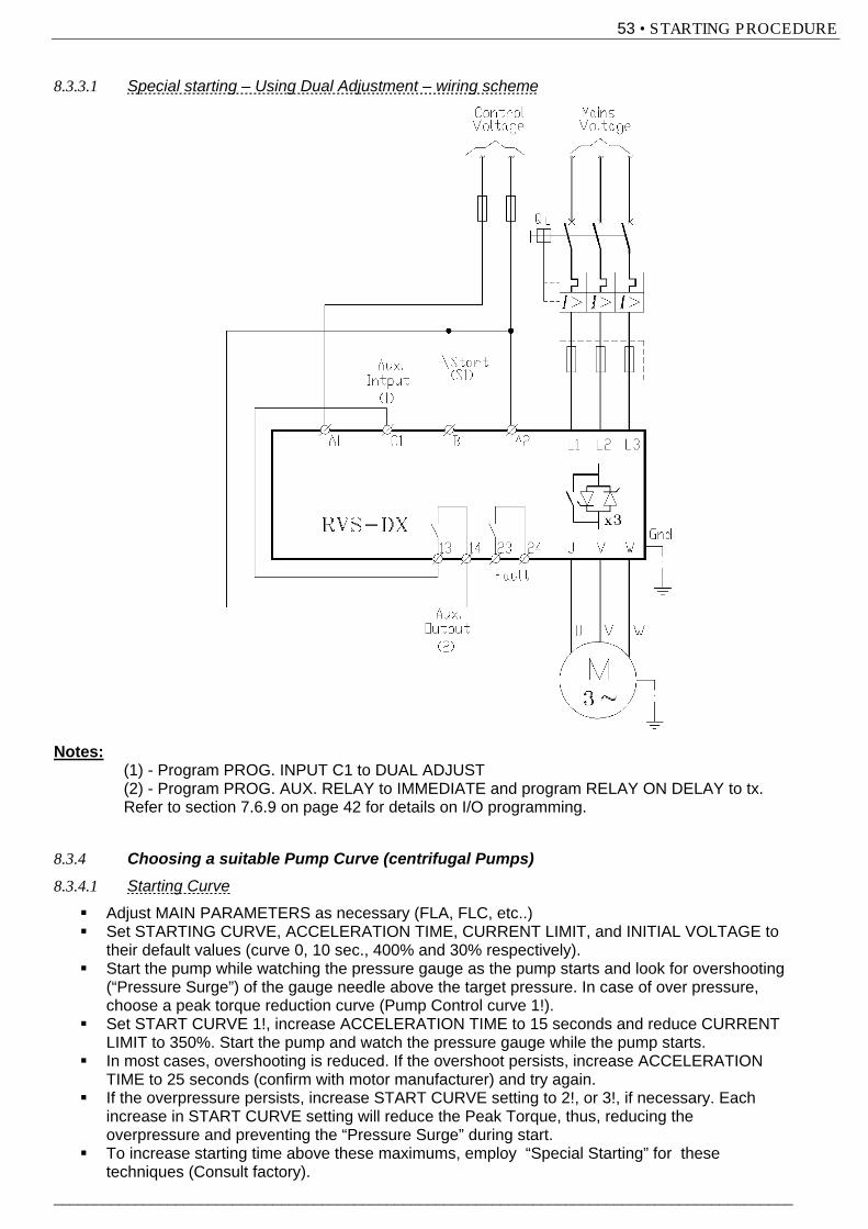
53 • STARTING PROCEDURE
___________________________________________________________________________________________
8.3.3.1 Special starting – Using Dual Adjustment – wiring scheme
Notes: (1) - Program PROG. INPUT C1 to DUAL ADJUST (2) - Program PROG. AUX. RELAY to IMMEDIATE and program RELAY ON DELAY to tx. Refer to section 7.6.9 on page 42 for details on I/O programming. 8.3.4 Choosing a suitable Pump Curve (centrifugal Pumps) 8.3.4.1 Starting Curve
Adjust MAIN PARAMETERS as necessary (FLA, FLC, etc..) Set STARTING CURVE, ACCELERATION TIME, CURRENT LIMIT, and INITIAL VOLTAGE to
their default values (curve 0, 10 sec., 400% and 30% respectively). Start the pump while watching the pressure gauge as the pump starts and look for overshooting
(“Pressure Surge”) of the gauge needle above the target pressure. In case of over pressure, choose a peak torque reduction curve (Pump Control curve 1!).
Set START CURVE 1!, increase ACCELERATION TIME to 15 seconds and reduce CURRENT LIMIT to 350%. Start the pump and watch the pressure gauge while the pump starts.
In most cases, overshooting is reduced. If the overshoot persists, increase ACCELERATION TIME to 25 seconds (confirm with motor manufacturer) and try again.
If the overpressure persists, increase START CURVE setting to 2!, or 3!, if necessary. Each increase in START CURVE setting will reduce the Peak Torque, thus, reducing the overpressure and preventing the “Pressure Surge” during start.
To increase starting time above these maximums, employ “Special Starting” for these techniques (Consult factory).

54 • STARTING PROCEDURE
________________________________________________________________________________________
8.3.4.2 Stopping Curve
Adjust MAIN PARAMETERS as necessary (FLA, FLC, etc..) Set STOP CURVE and DECELERATION TIME, to their default values (curve 0, 10 sec.,
respectively). Stop the pump, watching the pressure gauge and check valve as the pump stops. Look for
overshooting (“Water Hammer”) of the gauge (abruptly stops the pump and the motor). Select STOP CURVE 1, increase DECELERATION TIME to 15 seconds. Stop the pump and
watch the pressure gauge and the rate of closing of the check valve as the pump stops. Abrupt stopping of the pump and motor will cause a loud audible noise emitted from the check valve.
In most cases, “Water Hammer” is reduced. If the “Water Hammer” persists, increase the time to 25 seconds (confirm with motor manufacturer) and try again.
If the “Water Hammer” persists, increase STOP CURVE setting to 2!, or 3!. Each increase in STOP CURVE will reduce the abrupt stop of the pump, thus, preventing the “Water Hammer” phenomenon.
8.3.4.3 Final torque during soft-stopping a pump motor
While decelerating, the check valve may close before DECELERATION TIME has elapsed, thus, allowing current to flow through stator winding causing unnecessary heat. Select FINAL TORQUE sensitivity to 1, and stop the pump, confirm that current stopped flowing through the motor shortly after the check valve closed. If current still flows more than 3-5 seconds after check valve closure, increase FINAL TORQUE up to 10 if necessary, to stop current flow earlier
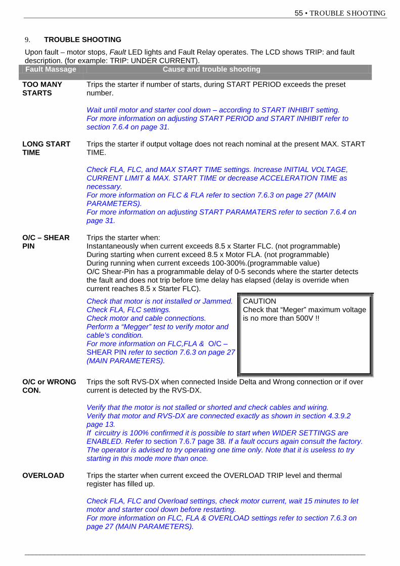
55 • TROUBLE SHOOTING
___________________________________________________________________________________________
9. TROUBLE SHOOTING Upon fault – motor stops, Fault LED lights and Fault Relay operates. The LCD shows TRIP: and fault description. (for example: TRIP: UNDER CURRENT). Fault Massage Cause and trouble shooting
TOO MANY STARTS
Trips the starter if number of starts, during START PERIOD exceeds the preset number. Wait until motor and starter cool down – according to START INHIBIT setting. For more information on adjusting START PERIOD and START INHIBIT refer to section 7.6.4 on page 31.
LONG START TIME
Trips the starter if output voltage does not reach nominal at the present MAX. START TIME. Check FLA, FLC, and MAX START TIME settings. Increase INITIAL VOLTAGE, CURRENT LIMIT & MAX. START TIME or decrease ACCELERATION TIME as necessary. For more information on FLC & FLA refer to section 7.6.3 on page 27 (MAIN PARAMETERS). For more information on adjusting START PARAMATERS refer to section 7.6.4 on page 31.
O/C – SHEAR PIN
Trips the starter when: Instantaneously when current exceeds 8.5 x Starter FLC. (not programmable) During starting when current exceed 8.5 x Motor FLA. (not programmable) During running when current exceeds 100-300%.(programmable value) O/C Shear-Pin has a programmable delay of 0-5 seconds where the starter detects the fault and does not trip before time delay has elapsed (delay is override when current reaches 8.5 x Starter FLC).
Check that motor is not installed or Jammed. Check FLA, FLC settings. Check motor and cable connections. Perform a “Megger” test to verify motor and cable’s condition. For more information on FLC,FLA & O/C – SHEAR PIN refer to section 7.6.3 on page 27 (MAIN PARAMETERS).
CAUTION Check that “Meger” maximum voltage is no more than 500V !!
O/C or WRONG CON.
Trips the soft RVS-DX when connected Inside Delta and Wrong connection or if over current is detected by the RVS-DX. Verify that the motor is not stalled or shorted and check cables and wiring. Verify that motor and RVS-DX are connected exactly as shown in section 4.3.9.2 page 13. If circuitry is 100% confirmed it is possible to start when WIDER SETTINGS are ENABLED. Refer to section 7.6.7 page 38. If a fault occurs again consult the factory. The operator is advised to try operating one time only. Note that it is useless to try starting in this mode more than once.
OVERLOAD Trips the starter when current exceed the OVERLOAD TRIP level and thermal register has filled up. Check FLA, FLC and Overload settings, check motor current, wait 15 minutes to let motor and starter cool down before restarting. For more information on FLC, FLA & OVERLOAD settings refer to section 7.6.3 on page 27 (MAIN PARAMETERS).
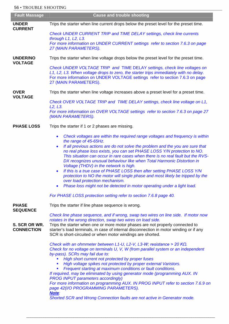
56 • TROUBLE SHOOTING
________________________________________________________________________________________
Fault Massage Cause and trouble shooting
UNDER CURRENT
Trips the starter when line current drops below the preset level for the preset time. Check UNDER CURRENT TRIP and TIME DELAY settings, check line currents through L1, L2, L3. For more information on UNDER CURRENT settings refer to section 7.6.3 on page 27 (MAIN PARAMETERS).
UNDER/NO VOLTAGE
Trips the starter when line voltage drops below the preset level for the preset time. Check UNDER VOLTAGE TRIP and TIME DELAY settings, check line voltages on L1, L2, L3. When voltage drops to zero, the starter trips immediately with no delay. For more information on UNDER VOLTAGE settings refer to section 7.6.3 on page 27 (MAIN PARAMETERS).
OVER VOLTAGE
Trips the starter when line voltage increases above a preset level for a preset time. Check OVER VOLTAGE TRIP and TIME DELAY settings, check line voltage on L1, L2, L3. For more information on OVER VOLTAGE settings refer to section 7.6.3 on page 27 (MAIN PARAMETERS).
PHASE LOSS Trips the starter if 1 or 2 phases are missing.
• Check voltages are within the required range voltages and frequency is within the range of 45-65Hz.
• If all previous actions are do not solve the problem and the you are sure that no real phase loss exists, you can set PHASE LOSS Y/N protection to NO. This situation can occur in rare cases when there is no real fault but the RVS-DX recognizes unusual behaviour like when Total Harmonic Distortion in Voltage (THDV) in the network is high.
• If this is a true case of PHASE LOSS then after setting PHASE LOSS Y/N protection to NO the motor will single phase and most likely be tripped by the over load protection mechanism.
• Phase loss might not be detected in motor operating under a light load. For PHASE LOSS protection setting refer to section 7.6.8 page 40.
PHASE SEQUENCE
Trips the starter if line phase sequence is wrong. Check line phase sequence, and if wrong, swap two wires on line side. If motor now rotates in the wrong direction, swap two wires on load side.
S. SCR OR WR. CONNECTION
Trips the starter when one or more motor phases are not properly connected to starter’s load terminals, in case of internal disconnection in motor winding or if any SCR is short-circuited or when motor windings are shorted. Check with an ohmmeter between L1-U, L2-V, L3-W; resistance > 20 KΩ. Check for no voltage on terminals U, V, W (from parallel system or an independent by-pass). SCRs may fail due to: High short current not protected by proper fuses High voltage spikes not protected by proper external Varistors. Frequent starting at maximum conditions or fault conditions.
If required, may be eliminated by using generator mode (programming AUX. IN PROG INPUT parameters accordingly) For more information on programming AUX. IN PROG INPUT refer to section 7.6.9 on page 42(I/O PROGRAMMING PARAMETERS). Note: Shorted SCR and Wrong Connection faults are not active in Generator mode.
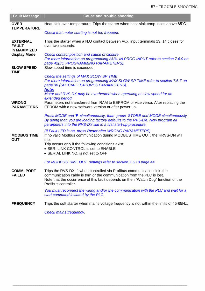
57 • TROUBLE SHOOTING
___________________________________________________________________________________________
Fault Massage Cause and trouble shooting
OVER TEMPERATURE
Heat-sink over-temperature. Trips the starter when heat-sink temp. rises above 85˚C. Check that motor starting is not too frequent.
EXTERNAL FAULT In MAXIMIZED display Mode
Trips the starter when a N.O contact between Aux. input terminals 13, 14 closes for over two seconds. Check contact position and cause of closure. For more information on programming AUX. IN PROG INPUT refer to section 7.6.9 on page 42(I/O PROGRAMMING PARAMETERS).
SLOW SPEED TIME
Slow speed time is exceeded. Check the settings of MAX SLOW SP TIME. For more information on programming MAX SLOW SP TIME refer to section 7.6.7 on page 38 (SPECIAL FEATURES PARAMETERS). Note: Motor and RVS-DX may be overheated when operating at slow speed for an extended period.
WRONG PARAMETERS
Parameters not transferred from RAM to EEPROM or vice versa. After replacing the EPROM with a new software version or after power up. Press MODE and ▼ simultaneously, than press STORE and MODE simultaneously. By doing that, you are loading factory defaults to the RVS-DX. Now program all parameters into the RVS-DX like in a first start-up procedure.
(If Fault LED is on, press Reset after WRONG PARAMETERS). MODBUS TIME OUT
If no valid Modbus communication during MODBUS TIME OUT, the HRVS-DN will trip. Trip occurs only if the following conditions exist: • SER. LINK CONTROL is set to ENABLE • SERIAL LINK NO. is not set to OFF For MODBUS TIME OUT settings refer to section 7.6.10 page 44.
COMM. PORT FAILED
Trips the RVS-DX if, when controlled via Profibus communication link, the communication cable is torn or the communication from the PLC is lost. Note that the occurrence of this fault depends on then “Watch Dog” function of the Profibus controller.
You must reconnect the wiring and/or the communication with the PLC and wait for a start command initiated by the PLC.
FREQUENCY Trips the soft starter when mains voltage frequency is not within the limits of 45-65Hz. Check mains frequency.
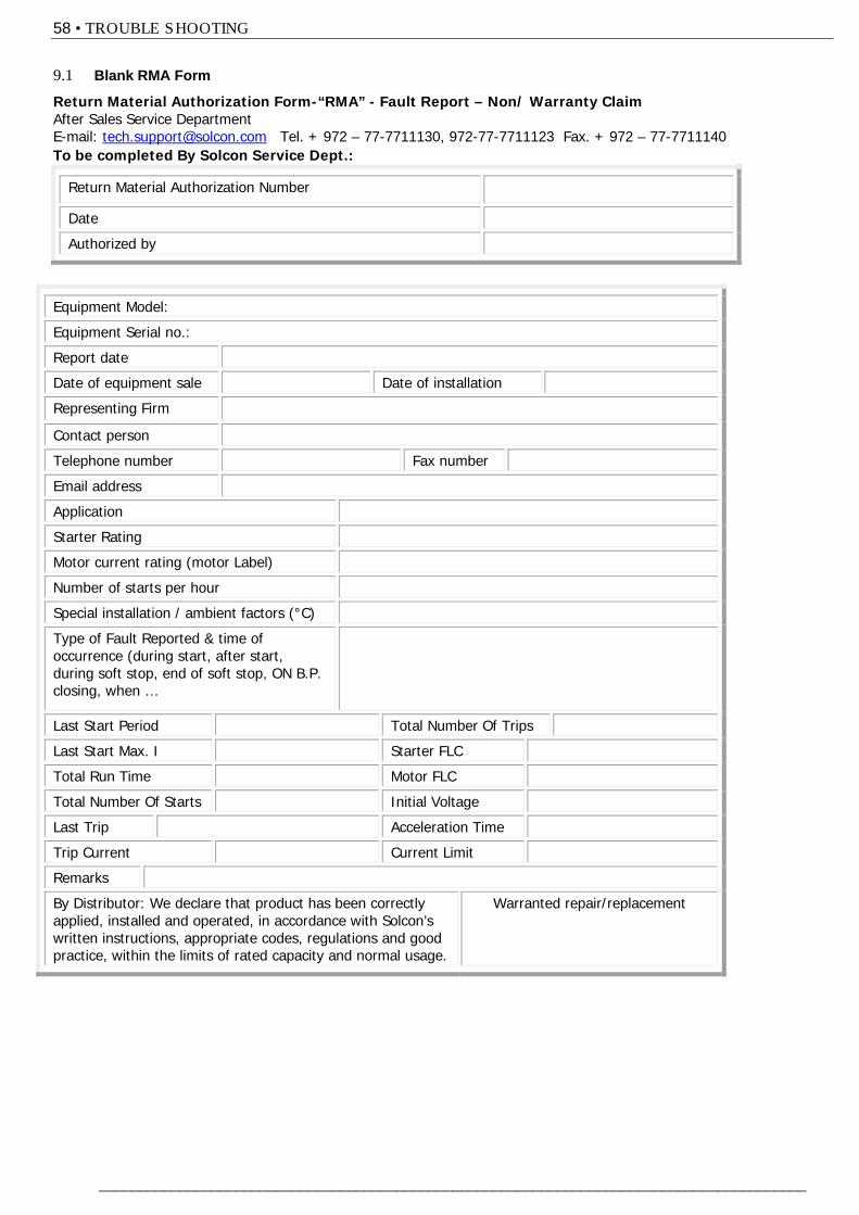
58 • TROUBLE SHOOTING
________________________________________________________________________________________
9.1 Blank RMA Form
Return Material Authorization Form-“RMA” - Fault Report – Non/ Warranty Claim After Sales Service Department E-mail: [email protected] Tel. + 972 – 77-7711130, 972-77-7711123 Fax. + 972 – 77-7711140 To be completed By Solcon Service Dept.:
Return Material Authorization Number
Date
Authorized by
Equipment Model:
Equipment Serial no.:
Report date
Date of equipment sale Date of installation
Representing Firm
Contact person
Telephone number Fax number
Email address
Application
Starter Rating
Motor current rating (motor Label)
Number of starts per hour
Special installation / ambient factors (°C)
Type of Fault Reported & time of occurrence (during start, after start, during soft stop, end of soft stop, ON B.P. closing, when …
Last Start Period Total Number Of Trips
Last Start Max. I Starter FLC
Total Run Time Motor FLC
Total Number Of Starts Initial Voltage
Last Trip Acceleration Time
Trip Current Current Limit
Remarks
By Distributor: We declare that product has been correctly applied, installed and operated, in accordance with Solcon’s written instructions, appropriate codes, regulations and good practice, within the limits of rated capacity and normal usage.
Warranted repair/replacement
59 • TECHNICAL SPECIFICATIONS:
___________________________________________________________________________________________
10. TECHNICAL SPECIFICATIONS: Supply Voltage Line to Line 230-600V (to be specified) + 10%-15% for all models Line to Line 690V (to be specified) + 10%-15% for RVS-DX 390A and up Frequency 45 – 65 Hz (Fixed or variable frequency source) Control Supply 115V or 230V (to be specified) +10% - 15% Load Three phases, three wires, squirrel cage induction motor. Start-Stop Parameters: Starter FLC Starter’s Full Load Current, according to Selector Guide Motor FLA Motor Full Load Ampere 50-100% of Starter FLC (Full Load Current). Pump and Torque Control Curves Field selectable curves preventing Over-pressure during start and Water
Hammer during stop. Pulse Start Duration A pulse of 80% Un, adjustable range 0.1-1 Sec, for starting high friction loads. Initial Voltage, 5-80% Un Initial Current 100-400% of Motor FLA Current Limit 100-500% of Motor FLA Acceleration Time 1-90 Sec Deceleration Time 1-90 Sec Motor Protection: Too Many Starts Maximum number of starts, range: Off or 1-10, during a time period 1-60 min. Starts inhibit Period of 1-60 min, during which starting is prevented, after Too Many Start
fault. Long Start Time (Stall protection) Maximum allowable starting time 1-30 sec. (1-250sec. in WIDER SETTINGS) Over Current (Shear-pin) Two operation functions: during starting trips the starter at 850% and during
running at 100-850% In, both within 1 Cycle (after internal delay). Electronic Overload (I2t) Adjustable IEC and MEMA curves. Under Current Trips when current drops below 20-90% In, time delay 1-40 sec. Under Voltage* Trips when main voltage drops below 50-90%, time delay 1-10 Sec Over Voltage Trips when main voltage increase above 110-125%, time delay 1-10 sec. Phase Loss, Under/Over Frequency* Trips when one or two phases are missing and frequency is 45Hz. or 65Hz. Phase Sequence Trips when phase sequence is wrong Shorted SCR or Wrong connection Prevents starting, trips if motor is not connected / incorrectly connected to the
starter, or in case one or more SCRs have been shorted Heat Sink Over temp Trips when heat-sink temperature rises above 85˚C. External fault Trips when an External Contact closes for 2 sec. * With optional Auto Reset. Control: Displays LCD in 4 – Field selectable languages and 4 LEDs. Keypad 6 keys for easy setting Fault Contact 2 Contacts, 8A, 250VAC, 2000VA Aux. Contact – Imm. or End Of Acc. 2 Contacts, 8A, 250VAC, 2000VA Temperatures: Operating -10˚ to 40˚C
Storage -20˚ to 70˚C Standards: Dielectric Test 2500VAC Degree of Protection IP 20 for frame size D1, IP 00 for frame sizes D2-D5 EMC Emissions EN 55011 CISPR 11 Class A Immunity EN 55082-2 ESD 8KV air, IEC 801-2 Electric RF field 10 V/m, 20-1000MHz, IEC 801-3 Fast transients 2KV, IEC 801-4 Safety EN 600947-1 Related to safety requirements. Designed and assembled to conform with UL508C
60 • TECHNICAL SPECIFICATIONS:
________________________________________________________________________________________
Normal Service Conditions:Altitude Up to 1000m. For equipment to be used at higher altitudes consult Factory.Humidity 95% at 50˚C or 98% at 45˚C.
Control Power ConsumptionThe approx. consumption of RVS-DX soft starters is as follows:
Model Before bypassClosed
Inrush Duringbypass closing
After bypass closed
8 20VA 20VA 20VA17 20VA 20VA 20VA31 20VA 20VA 20VA44 20VA 20VA 20VA58 20VA 20VA 20VA72 20VA 20VA 20VA85 20VA 20VA 20VA
105 20VA 20VA 20VA145 20VA 20VA 20VA170 20VA 20VA 20VA210 20VA 30VA 30VA310 20VA 30VA 30VA390 20VA 600VA 40VA460 20VA 800VA 40VA580 20VA 1700VA 40VA820 20VA 1700VA 40VA950 20VA 2400VA 60VA1100 20VA 2400VA 60VA
Notes:
Solcon Industries Ltd.www.solcon.com; Technical support: [email protected]