rsview32: communicating to powerflex drives on...
TRANSCRIPT
Preliminary Rev Page 1 of 28
RSView32: Communicating to PowerFlex Drives on Ethernet, ControlNet, & DeviceNet using DDE w/ CIP Messages
February 26th, 2003
Background
RSView32 is a Windows based program that can be used to capture data, monitor, and control plant-wide systems. DDE (Dynamic Data Exchange) can be used to directly monitor or modify data from PowerFlex VFDs on Ethernet, ControlNet, or DeviceNet. This means an intermediate PLC is not needed to collect the data before sending it to an RSView32 application.
Application Note Objectives
This application note will show an example of creating a project in RSView32, creating tags to collect data from a PowerFlex VFD on Ethernet, ControlNet or DeviceNet, and using tags to display or modify VFD data in RSView32. This note applies to the PowerFlex 70, PowerFlex 700, and PowerFlex 700 with vector control using the 20-COMM-E (Ethernet), 20-COMM-C (ControlNet), or 20-COMM-D (DeviceNet) communication adapters.
Conventions Used in This Application Note
� FYI: Provides additional information that is useful, but is not necessary to complete the application.
� ATTENTION: Identifies information about practices or circumstances that can lead to personal injury or death, property damage or economic loss. Attention statements help you identify a hazard, avoid a hazard, and recognize the consequences.
Software Used
This note uses RSView32 Works v6.30.16 and RSLinx v2.40.01 (Build 16).

Preliminary Rev Page 2 of 28
Table of Contents
RSVIEW32: COMMUNICATING TO VFDS ON ETHERNET, CONTROLNET, & DEVICENET USING DDE W/ CIP MESSAGES............................................................................................. 1
BACKGROUND ....................................................................................................................... 1
1. NETWORK CONFIGURATION ............................................................................................ 3
2. CREATE AN RSVIEW32 PROJECT..................................................................................... 4
3. CREATE A DDE TOPIC USING RSLINX ............................................................................ 5
4. CREATE A DDE NODE IN RSVIEW32................................................................................. 8
5. CREATE A TAG IN RSVIEW................................................................................................ 9
6. CREATE A DISPLAY SCREEN IN RSVIEW32 .................................................................. 13
7. TESTING THE DISPLAY IN RUN MODE ........................................................................... 15
8. CREATING A NUMERIC INPUT TO CHANGE A DRIVE PARAMETER............................ 16
9. CREATING A DRIVE STATUS INDICATOR ..................................................................... 18
10. CONTROLLING THE DRIVE USING THE REGISTER OBJECT ...................................... 20
Preliminary Rev Page 3 of 28
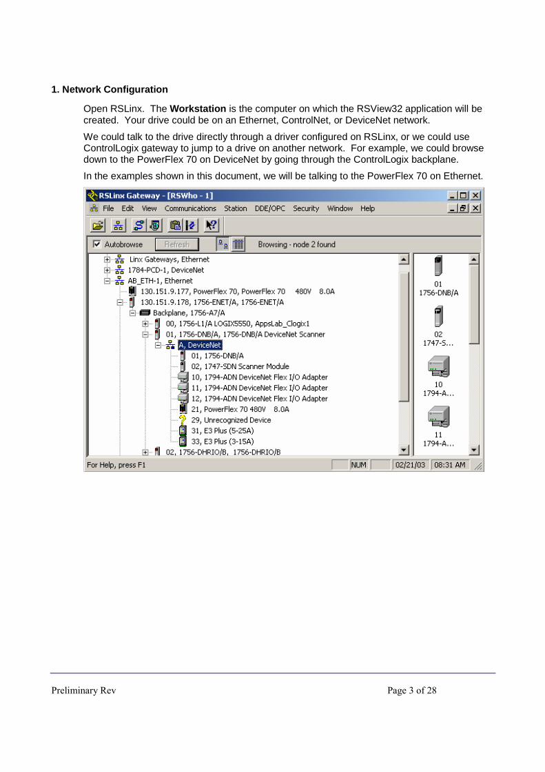
1. Network Configuration
Open RSLinx. The Workstation is the computer on which the RSView32 application will be created. Your drive could be on an Ethernet, ControlNet, or DeviceNet network.
We could talk to the drive directly through a driver configured on RSLinx, or we could use ControlLogix gateway to jump to a drive on another network. For example, we could browse down to the PowerFlex 70 on DeviceNet by going through the ControlLogix backplane.
In the examples shown in this document, we will be talking to the PowerFlex 70 on Ethernet.
Preliminary Rev Page 4 of 28
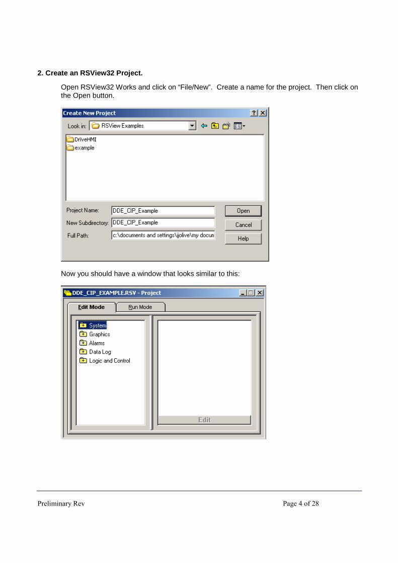
2. Create an RSView32 Project.
Open RSView32 Works and click on “File/New”. Create a name for the project. Then click on the Open button.
Now you should have a window that looks similar to this:
Preliminary Rev Page 5 of 28
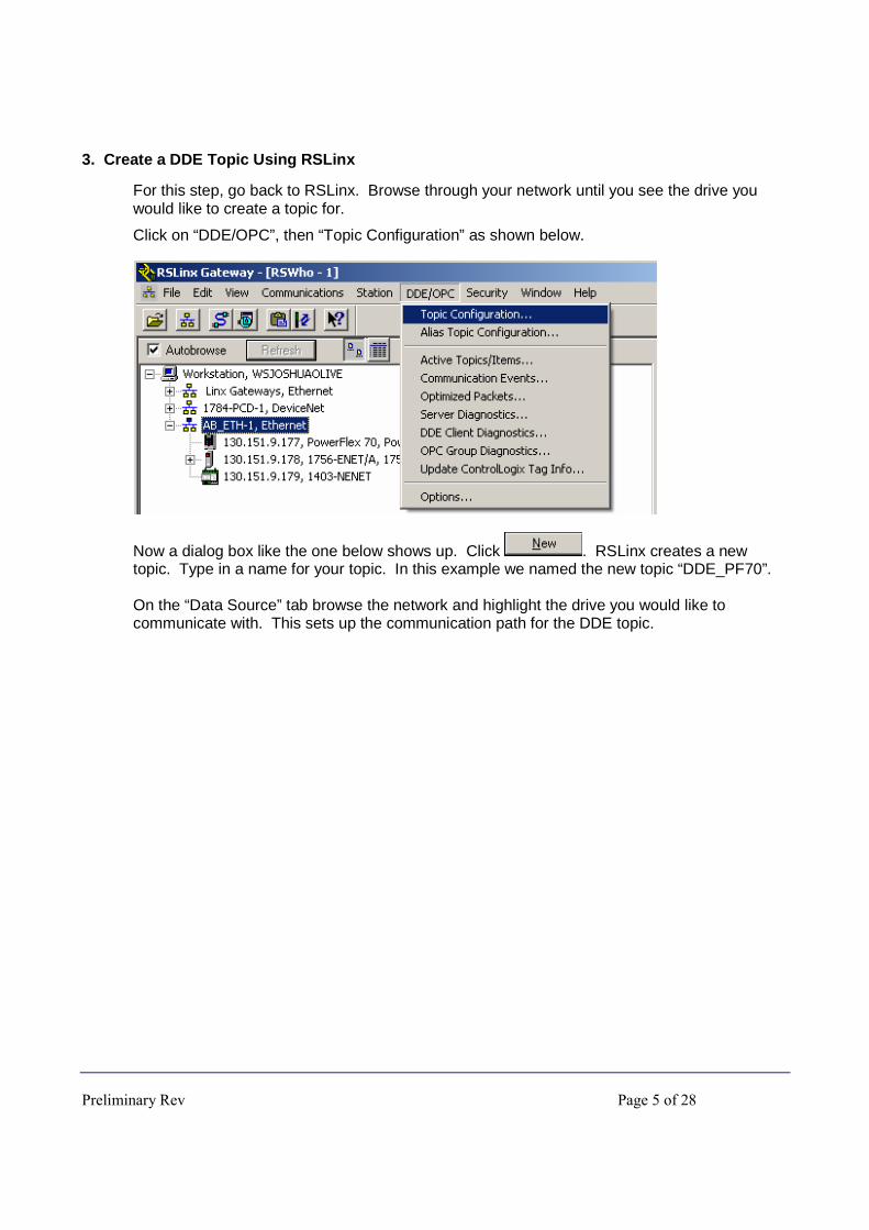
3. Create a DDE Topic Using RSLinx
For this step, go back to RSLinx. Browse through your network until you see the drive you would like to create a topic for.
Click on “DDE/OPC”, then “Topic Configuration” as shown below.
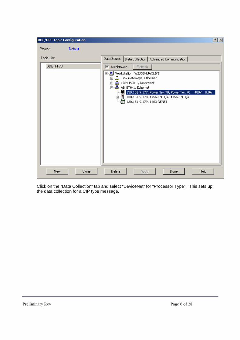
Now a dialog box like the one below shows up. Click . RSLinx creates a new topic. Type in a name for your topic. In this example we named the new topic “DDE_PF70”. On the “Data Source” tab browse the network and highlight the drive you would like to communicate with. This sets up the communication path for the DDE topic.
Preliminary Rev Page 6 of 28
Click on the “Data Collection” tab and select “DeviceNet” for “Processor Type”. This sets up the data collection for a CIP type message.

Preliminary Rev Page 7 of 28
Click on the “Apply button” to apply the changes to your new topic.
After applying the changes, you can click on the “Advanced Communication” tab to verify that the communication path is correct. Note that when we highlighted the PowerFlex 70 on Ethernet, RSLinx automatically created the correct path because the PowerFlex 70 was highlighted. Here is an explanation of the address “AB ETH-1\0.(130.151.9.177)” that appears for our example: “AB ETH-1” � Indicates we are using the Ethernet driver in RSLinx. “0” � Indicates we are going out the Ethernet card on the Workstation. “(130.151.9.177)” � Indicates the Ethernet IP address of the PowerFlex 70 on Ethernet. Click on the “Done” button once you have verified the settings. When RSLinx asks you to update the topic click “Yes”.

Preliminary Rev Page 8 of 28
4. Create a DDE Node in RSView32
Go back into RSView32. Expand the System folder and double click on Node.
A Node dialog box appears. Select DDE Server for the Data Source. Then give the new node a name. In this example, we named it “PF70”. For “Application” type “RSLinx” since that will be the source of our data. For “Topic” type in the name of the topic that you created in RSLinx. In this example the topic name is “DDE_PF70”. Now you are done creating the node, so click on the “Accept” button to accept the node. Then close the Node dialog box.
Preliminary Rev Page 9 of 28
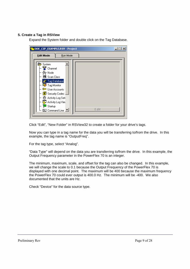
5. Create a Tag in RSView Expand the System folder and double click on the Tag Database.
Click “Edit”, “New Folder” in RSView32 to create a folder for your drive’s tags.
Now you can type in a tag name for the data you will be transferring to/from the drive. In this example, the tag name is “OutputFreq”.
For the tag type, select “Analog”.
“Data Type” will depend on the data you are transferring to/from the drive. In this example, the Output Frequency parameter in the PowerFlex 70 is an integer.
The minimum, maximum, scale, and offset for the tag can also be changed. In this example, we will change the scale to 0.1 because the Output Frequency of the PowerFlex 70 is displayed with one decimal point. The maximum will be 400 because the maximum frequency the PowerFlex 70 could ever output is 400.0 Hz. The minimum will be -400. We also documented that the units are Hz.
Check “Device” for the data source type.
Preliminary Rev Page 10 of 28
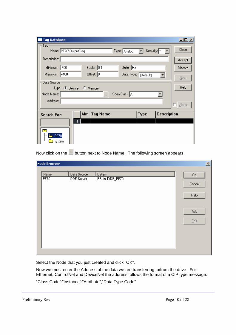
Now click on the button next to Node Name. The following screen appears.
Select the Node that you just created and click “OK”.
Now we must enter the Address of the data we are transferring to/from the drive. For Ethernet, ControlNet and DeviceNet the address follows the format of a CIP type message:
“Class Code”:”Instance”:”Attribute”,”Data Type Code”
Preliminary Rev Page 11 of 28
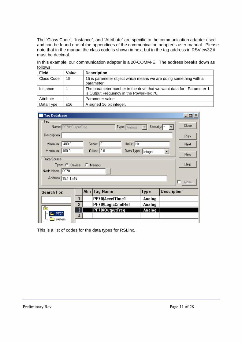
The “Class Code”, “Instance”, and “Attribute” are specific to the communication adapter used and can be found one of the appendices of the communication adapter’s user manual. Please note that in the manual the class code is shown in hex, but in the tag address in RSView32 it must be decimal.
In this example, our communication adapter is a 20-COMM-E. The address breaks down as follows: Field Value Description Class Code 15 15 is parameter object which means we are doing something with a
parameter Instance 1 The parameter number in the drive that we want data for. Parameter 1
is Output Frequency in the PowerFlex 70. Attribute 1 Parameter value. Data Type s16 A signed 16 bit integer.
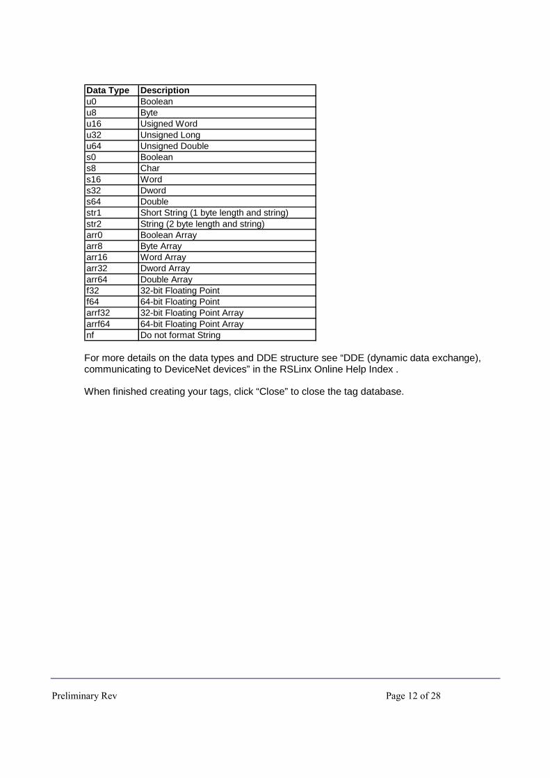
This is a list of codes for the data types for RSLinx.
Preliminary Rev Page 12 of 28
Data Type Descriptionu0 Booleanu8 Byteu16 Usigned Wordu32 Unsigned Longu64 Unsigned Doubles0 Booleans8 Chars16 Words32 Dwords64 Doublestr1 Short String (1 byte length and string)str2 String (2 byte length and string)arr0 Boolean Arrayarr8 Byte Arrayarr16 Word Arrayarr32 Dword Arrayarr64 Double Arrayf32 32-bit Floating Pointf64 64-bit Floating Pointarrf32 32-bit Floating Point Arrayarrf64 64-bit Floating Point Arraynf Do not format String
For more details on the data types and DDE structure see “DDE (dynamic data exchange), communicating to DeviceNet devices” in the RSLinx Online Help Index .
When finished creating your tags, click “Close” to close the tag database.
Preliminary Rev Page 13 of 28
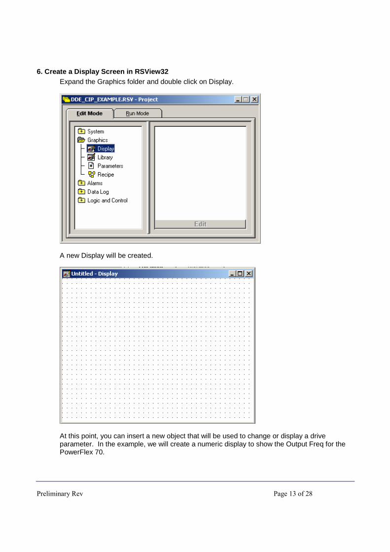
6. Create a Display Screen in RSView32 Expand the Graphics folder and double click on Display.
A new Display will be created.
At this point, you can insert a new object that will be used to change or display a drive parameter. In the example, we will create a numeric display to show the Output Freq for the PowerFlex 70.

Preliminary Rev Page 14 of 28
Click on the button once to create a numeric display. Select a spot on the display screen to create the numeric display, then click the left mouse button and drag to create a numeric display of a desired size. Once you lift your finger off of the left mouse button the following dialog box appears.
Now type in the tag name (including the folder name) or click on “Tags…” to select the tag. Select the correct format for the parameter you are monitoring, and setup the number of decimal places, if there are any. Choose floating point for the format in order to show any decimal places. We will display one decimal place for the output frequency:
Notice that in the Numeric Display dialog box you can add logical and arithmetic instructions to manipulate the tag data before it is displayed.
Be sure to save the new display screen.
Preliminary Rev Page 15 of 28
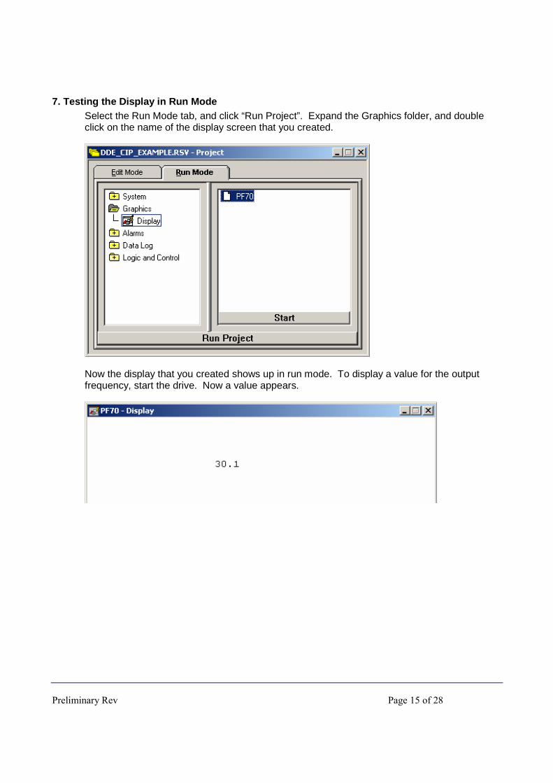
7. Testing the Display in Run Mode Select the Run Mode tab, and click “Run Project”. Expand the Graphics folder, and double click on the name of the display screen that you created.
Now the display that you created shows up in run mode. To display a value for the output frequency, start the drive. Now a value appears.
Preliminary Rev Page 16 of 28
8. Creating a Numeric Input to Change a Drive Parameter
� ATTENTION: Using explicit messaging to make frequent changes to a parameter will eventually result in the failure of the device’s EEPROM (if so equipped). If an application requires frequent changes of only a few parameters, the parameters should be written using the adapter’s Datalink function (if available) since this does not cause EEPROM writes to occur.
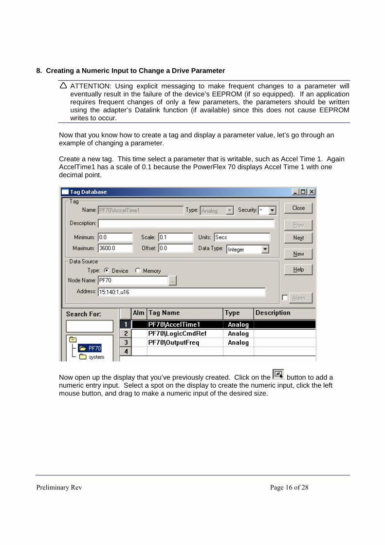
Now that you know how to create a tag and display a parameter value, let’s go through an example of changing a parameter. Create a new tag. This time select a parameter that is writable, such as Accel Time 1. Again AccelTime1 has a scale of 0.1 because the PowerFlex 70 displays Accel Time 1 with one decimal point.
Now open up the display that you’ve previously created. Click on the button to add a numeric entry input. Select a spot on the display to create the numeric input, click the left mouse button, and drag to make a numeric input of the desired size.

Preliminary Rev Page 17 of 28
Select the tag name for the parameter that you wish to change. In this example, we chose to display 2 decimal places. Click “OK” to close the Numeric Display dialog box.
Save the display. Notice that in the example we added some more text to make the display screen look a little nicer.
Once again, we can go to run mode to test the numeric input.
To change the input highlight it and type in the new value that you want to be written to the drive parameter.
Preliminary Rev Page 18 of 28
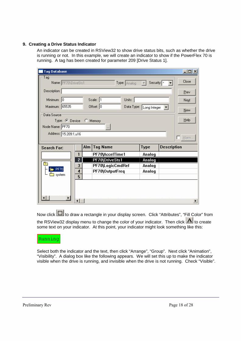
9. Creating a Drive Status Indicator An indicator can be created in RSView32 to show drive status bits, such as whether the drive is running or not. In this example, we will create an indicator to show if the PowerFlex 70 is running. A tag has been created for parameter 209 [Drive Status 1].
Now click to draw a rectangle in your display screen. Click “Attributes”, “Fill Color” from
the RSView32 display menu to change the color of your indicator. Then click to create some text on your indicator. At this point, your indicator might look something like this:
Select both the indicator and the text, then click “Arrange”, “Group”. Next click “Animation”, “Visibility”. A dialog box like the following appears. We will set this up to make the indicator visible when the drive is running, and invisible when the drive is not running. Check “Visible”.

Preliminary Rev Page 19 of 28
Now click on the “Expression” button. This brings up another dialog box. Type in the name of the status tag you wish to use or choose the tag using the “Tags…” button. Then click “Bitwise” and select the “&” operator. Finally, type in the decimal value for the status parameter that indicates the desired state. In this example, bit 1 (a decimal value of 2) indicates that the drive is running. The final expression for our example is shown below. Now our indicator will be visible when bit 1 of parameter 209 is on, and invisible when bit 1 is off. Click “OK” to close the “Expression” window and click “Apply”, then “Close” to close the “Animation” dialog box.
Now you can go into run mode to test the new indicator.
Preliminary Rev Page 20 of 28
10. Controlling the drive using the Register Object
� FYI: Writing to the Register Object does not write to the EEPROM. Instead, it writes to volatile memory. Therefore, the Datalinks in the Register Object can be used for writing parameters that are changed frequently.
Several of the communication adapters support the Register Object (Class Code 7). The Register Object can be used to write to the logic command, reference, Datalinks and to read the drive status, feedback, and Datalinks using CIP messages.
When controlling the drive from RSView32 using CIP messaging there is no continuous communication connection to the drive. To prevent a communication loss fault on the drive, the communication adapter’s [Comm Fault Action] and [Idle Flt Action] parameters can be set to “Hold Last”.
� ATTENTION: Risk of injury or equipment damage exists. [Comm Flt Action] lets you determine the action of the adapter and connected drive if communications are disrupted. By default, this parameter faults the drive. You can set this parameter so that the drive continues to run. Precautions should be taken to ensure that the setting of this parameter does not create a hazard of injury or equipment damage.
� ATTENTION: Risk of injury or equipment damage exists. [Idle Flt Action] lets you determine the action of the adapter and connected drive if the scanner is idle. By default, this parameter faults the drive. You can set this parameter so that the drive continues to run. Precautions should be taken to ensure that the setting of this parameter does not create a hazard of injury or equipment damage.
When using the 20-COMM-E or 20-COMM-C the control timeout must be set before the drive will allow control with the Register Object. This control timeout can be set by writing a value in seconds to Class 7, Instance 0, and Attribute 100.
In this example, we will write to the logic command of the PowerFlex 70 on Ethernet. We will create buttons in RSView32 to start, stop, and change the speed. Note that the logic command and reference in the 20-COMM-E register object are packed into the same 32 bit integer, where the logic command is the lower 16 bits and the reference is the upper 16 bits. To make the example easier, we will use the MOP (motor operated pot) function instead of writing the upper 16 bits of the register object to change the speed ref.

Preliminary Rev Page 21 of 28
Creating start and stop buttons:
Now we will create a start button. Go back to the display screen and click on to create a button. Then click and drag on the display screen to create a button of the desired size. The following dialog box appears:
Preliminary Rev Page 22 of 28
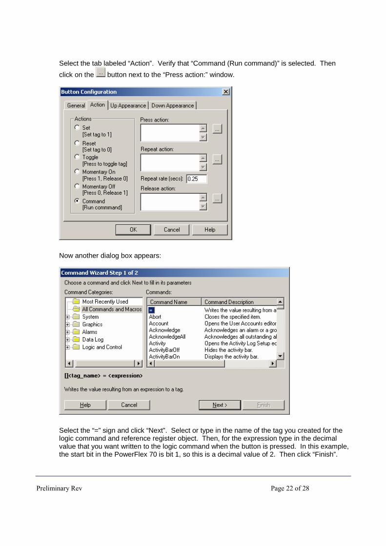
Select the tab labeled “Action”. Verify that “Command (Run command)” is selected. Then
click on the button next to the “Press action:” window.
Now another dialog box appears:
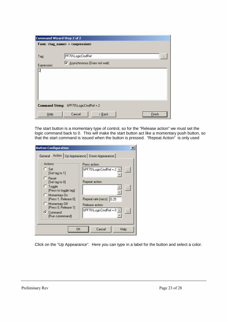
Select the “=” sign and click “Next”. Select or type in the name of the tag you created for the logic command and reference register object. Then, for the expression type in the decimal value that you want written to the logic command when the button is pressed. In this example, the start bit in the PowerFlex 70 is bit 1, so this is a decimal value of 2. Then click “Finish”.
Preliminary Rev Page 23 of 28
The start button is a momentary type of control, so for the “Release action” we must set the logic command back to 0. This will make the start button act like a momentary push button, so that the start command is issued when the button is pressed. “Repeat Action” is only used
Click on the “Up Appearance”. Here you can type in a label for the button and select a color.
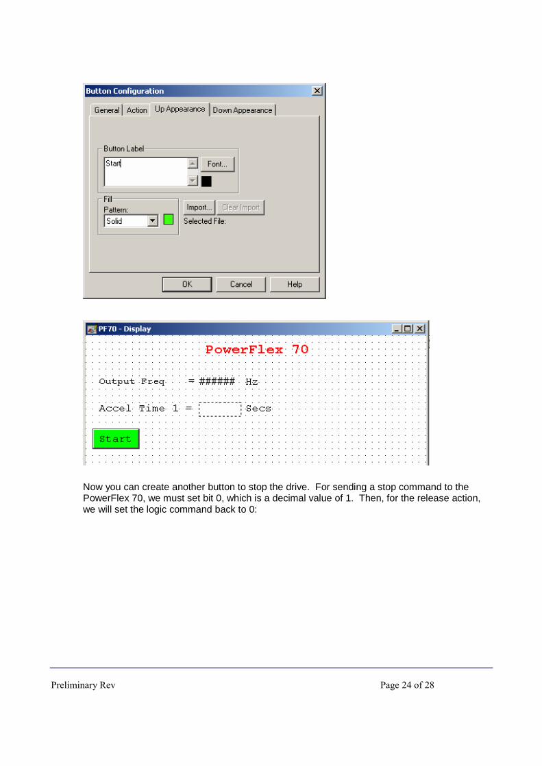
Preliminary Rev Page 24 of 28
Now you can create another button to stop the drive. For sending a stop command to the PowerFlex 70, we must set bit 0, which is a decimal value of 1. Then, for the release action, we will set the logic command back to 0:

Preliminary Rev Page 25 of 28
Creating forward and reverse buttons:
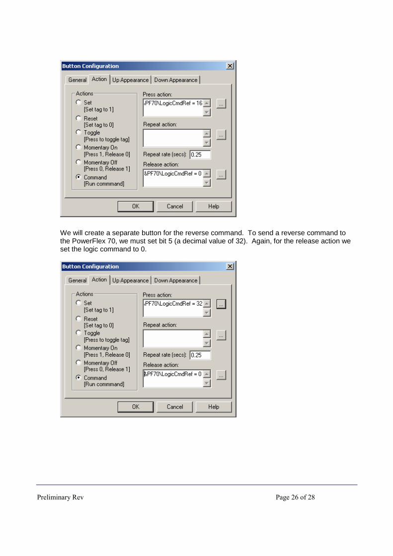
We will create another button for the forward command. To send a forward command to the PowerFlex 70, we must set bit 4 (a decimal value of 16). Again, for the release action we set the logic command to 0.
Preliminary Rev Page 26 of 28
We will create a separate button for the reverse command. To send a reverse command to the PowerFlex 70, we must set bit 5 (a decimal value of 32). Again, for the release action we set the logic command to 0.
Preliminary Rev Page 27 of 28
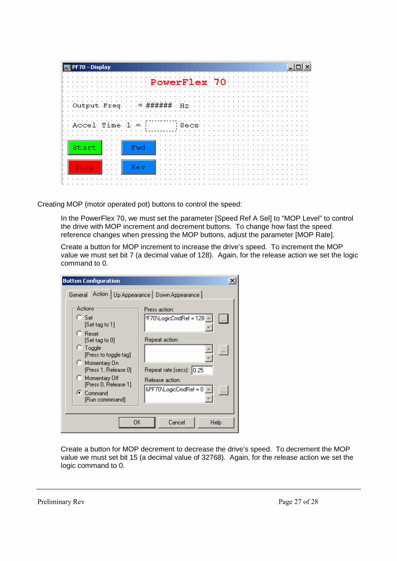
Creating MOP (motor operated pot) buttons to control the speed:
In the PowerFlex 70, we must set the parameter [Speed Ref A Sel] to “MOP Level” to control the drive with MOP increment and decrement buttons. To change how fast the speed reference changes when pressing the MOP buttons, adjust the parameter [MOP Rate].
Create a button for MOP increment to increase the drive’s speed. To increment the MOP value we must set bit 7 (a decimal value of 128). Again, for the release action we set the logic command to 0.
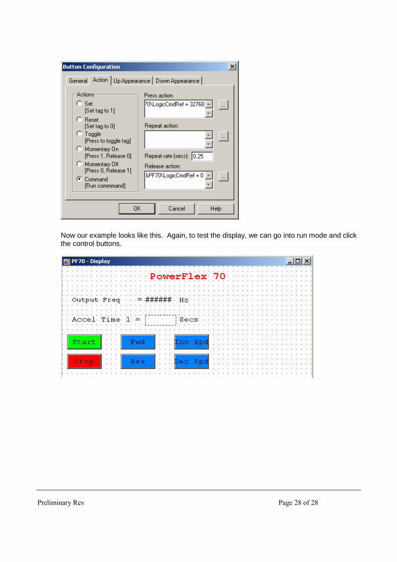
Create a button for MOP decrement to decrease the drive’s speed. To decrement the MOP value we must set bit 15 (a decimal value of 32768). Again, for the release action we set the logic command to 0.
Preliminary Rev Page 28 of 28
Now our example looks like this. Again, to test the display, we can go into run mode and click the control buttons.