rph.health.wa.gov.au/media/files/corporate/general documents...rph.health.wa.gov.au
TRANSCRIPT
C ode of
Code of Practice for the Design, Manufacture, Installation and Operation of Aerobic Treatment Units (ATU’s)
i
Design, Manufacture, Installation and Operation of Aerobic Treatment Units (ATUs)PART 1 - SPECIFICATION FOR DESIGN AND MANUFACTURE OF ATUS
1. Scope 2
2. Interpretation 2
3. ATU Design 3
4. ATU Description 4
5. Materials and Construction 7
6. Mechanical Equipment 8
7. Electrical Equipment 8
8. Noise 9
9. Compliance Testing 9
10 Maintenance 10
11. Warranty and Guaranteed Service Life 10
12. Drawings 10
13. Schedules of Guaranteed Technical Information 10
14. Basis of Design Parameters in Specification 10
Schedule No1 – Technical Information 11
Appendix 1 – Basis of Design Parameters in Specification 15
Appendix 2 – Test Procedure 20
PART 2 – INSTALLATION AND OPERATION OF ATUS
1. Scope 25
2. Introduction 25
3. System Approval 26
(a) Legislation 26 (b) Applications 26
4. Surface Irrigation 28
(a) Disposal Area 28 (b) Reduced Irrigation Areas for Sand Conditions 29 (c) Landscaping 30 (d) Irrigation System 30 (e) Phosphorus Retention 31
5. Sub-Soil Disposal System 32
6. Allotment Requirements 32
(a) Recreational/Social Area 32 (b) Set Back Distances 32 (c) Depth to Groundwater 34
- ii -
Clause Page No.
7. System Operation 34
8. Maintenance 34
(a) Maintaining the Surface Irrigation Disposal Area 35 (b) Maintenance Requirements 35 (c) Maintenance Reports 36
9. Permit to Use 36
10. General 36
APPENDICES
Appendix I - Suitable Plants 37 Appendix II - Glossary of Terms 39 Appendix III - Site Plan Layouts 41 Appendix IV - Check List (testing) 45 Appendix V - Dripper Irrigation Disposal System 46
- iii -
INTRODUCTION The Code of Practice for the Design, Manufacture, Installation and Operation of Aerobic Treatment Units (ATUs) Serving Single Dwellings [the Code] has been primarily developed as a set of minimum standards for the design, manufacture, installation and operation of ATUs, and provides guidance to local government as to how to assess the installation and ongoing operation of ATUs.
The Code is based on the following documents:
• “Specification for Aerobic Treatment Units (ATUs) Serving Single Dwellings”(1992)
published by the Department of Health • “Standard for the Installation and Operation of Aerobic Treatment Units (ATUs)
Serving Single Dwellings” (1992) published by the Department of Health. • “Standard for Dripper Irrigation Effluent Disposal System” (1994) published by the
Department of Health. • “Standard for the Installation and Operation of Septic Tank Systems in South
Australia, Supplement B - Aerobic Wastewater Treatment Systems” (1990) published by the South Australian Health Commission.
The Code, which was prepared by the Environmental Health Service of the Department of Health, is published by the Chief Health Officer under the provisions of section 344A(2) of the Health Act (Miscellaneous Provisions) 1911, and is to be read in conjunction with the Health (Treatment of Sewage and Disposal of Effluent and Liquid Waste) Regulations 1974.
Professor Tarun Weeramanthri CHIEF HEALTH OFFICER
Code of Practice for the Design Manufacture Installation and Operation of ATUs Serving Single Dwellings
1
PART 1
SPECIFICATION FOR THE DESIGN AND MANUFACTURE OF
AEROBIC TREATMENT UNITS (ATUs)
SERVING SINGLE DWELLINGS
2
Code of Practice for the Design Manufacture Installation and Operation of ATUs Serving Single Dwellings Part 1 Specification for the Design and Manufacture of ATUs Serving Single Dwellings
1. SCOPE
Part 1 of the Code sets out the requirements for the approval by the CHO of ATUs serving single dwellings using a combination of anaerobic and aerobic processes for the treatment and disposal of wastewater of domestic origin.
1.1 Variation from the Specification
The CHO may exempt a manufacturer of an ATU from complying with any requirement under this Part where it has been demonstrated that the particular ATU has been subjected to a testing program recognised by the CHO and demonstrated compliance with Clause 9.7 of this Part.
2. INTERPRETATION
Parts 1 and 2 of the Code shall be read in conjunction with the Health (Treatment of Sewage and Disposal of Effluent and Liquid Waste) Regulations 1974 and in addition to the meanings contained in those Regulations and the Health Act (Miscellaneous Provisions) 1911, and unless the contrary intention appears –
“AS” means Standards Association of Australia Standard.
“ATU” means Aerobic Treatment Unit, an apparatus for treating sewage either wholly or partially by aerobic means and includes any associated effluent disposal system;
“authorised person” means a person who is authorised under regulation 42C of the “Health (Treatment of Sewage and Disposal of Effluent and Liquid Waste) Regulations 1974” to carry out maintenance on an ATU.
“the Code” means the Code of Practice for the Design, Manufacture, Installation and Operation of Aerobic Treatment Units (ATUs) Serving Single Dwellings;
“CHO” means Chief Health Officer, the person holding or acting in the office of Chief Health Officer and Scientific Support Services in the Department;
“manufacturer” means the person, company or firm submitting the ATU for approval by the CHO and any nominated representative;
“the Regulations” means the “Health (Treatment of Sewage and Disposal of Effluent and Liquid Waste) Regulations 1974”
“wastewater” means liquid waste and solids, faecal matter and other matter carried in or by the liquid waste;
“5-day BOD”, “settleable solids” and “total suspended solids” have the same meaning as in the current edition of “Standard Methods for the Examination of Water and Wastewater” as published by the Water Environment Federation et al;
Code of Practice for the Design Manufacture Installation and Operation of ATUs Serving Single Dwellings
Part 1 Specification for the Design and Manufacture of ATUs Serving Single Dwellings
- 3 -
3. ATU DESIGN
3.1 The ATU shall incorporate the following processes; primary sedimentation, anaerobic and aerobic biological treatment and secondary sedimentation. Where above ground disposal is utilised a disinfection process shall also be incorporated.
3.2 The maximum allowable design capacity shall be limited to 10 persons.
3.3 The minimum allowable design capacity shall be 8 persons.
3.4 The ATU shall be designed to function normally between quarterly inspections by
an authorised person.
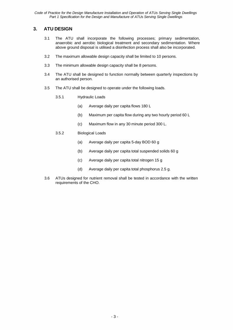
3.5 The ATU shall be designed to operate under the following loads.
3.5.1 Hydraulic Loads
(a) Average daily per capita flows 180 L
(b) Maximum per capita flow during any two hourly period 60 L
(c) Maximum flow in any 30 minute period 300 L.
3.5.2 Biological Loads
(a) Average daily per capita 5-day BOD 60 g
(b) Average daily per capita total suspended solids 60 g
(c) Average daily per capita total nitrogen 15 g
(d) Average daily per capita total phosphorus 2.5 g.
3.6 ATUs designed for nutrient removal shall be tested in accordance with the written requirements of the CHO.
Code of Practice for the Design Manufacture Installation and Operation of ATUs Serving Single Dwellings
Part 1 Specification for the Design and Manufacture of ATUs Serving Single Dwellings
- 4 -
4. ATU DESCRIPTION
The ATU shall consist of the following:
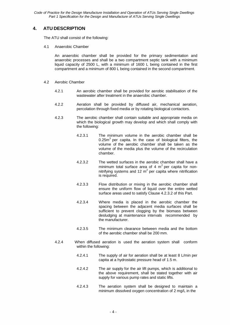
4.1 Anaerobic Chamber
An anaerobic chamber shall be provided for the primary sedimentation and anaerobic processes and shall be a two compartment septic tank with a minimum liquid capacity of 2500 L, with a minimum of 1600 L being contained in the first compartment and a minimum of 800 L being contained in the second compartment.
4.2 Aerobic Chamber
4.2.1 An aerobic chamber shall be provided for aerobic stabilisation of the wastewater after treatment in the anaerobic chamber.
4.2.2 Aeration shall be provided by diffused air, mechanical aeration,
percolation through fixed media or by rotating biological contactors.
4.2.3 The aerobic chamber shall contain suitable and appropriate media on which the biological growth may develop and which shall comply with the following:
4.2.3.1 The minimum volume in the aerobic chamber shall be
0.25m3 per capita. In the case of biological filters, the volume of the aerobic chamber shall be taken as the volume of the media plus the volume of the recirculation chamber.
4.2.3.2 The wetted surfaces in the aerobic chamber shall have a
minimum total surface area of 4 m2 per capita for non- nitrifying systems and 12 m2 per capita where nitrification is required.
4.2.3.3 Flow distribution or mixing in the aerobic chamber shall
ensure the uniform flow of liquid over the entire wetted surface areas used to satisfy Clause 4.2.3.2 of this Part.
4.2.3.4 Where media is placed in the aerobic chamber the
spacing between the adjacent media surfaces shall be sufficient to prevent clogging by the biomass between desludging at maintenance intervals recommended by the manufacturer.
4.2.3.5 The minimum clearance between media and the bottom
of the aerobic chamber shall be 200 mm.
4.2.4 When diffused aeration is used the aeration system shall conform within the following:
4.2.4.1 The supply of air for aeration shall be at least 8 L/min per
capita at a hydrostatic pressure head of 1.5 m.
4.2.4.2 The air supply for the air lift pumps, which is additional to the above requirement, shall be stated together with air supply for various pump rates and static lifts.
4.2.4.3 The aeration system shall be designed to maintain a
minimum dissolved oxygen concentration of 2 mg/L in the
Code of Practice for the Design Manufacture Installation and Operation of ATUs Serving Single Dwellings
Part 1 Specification for the Design and Manufacture of ATUs Serving Single Dwellings
- 5 -
aerobic chamber under the maximum two hourly flow as defined in 3.5.1(b).
4.2.4.4 The air supply to the aerobic chamber shall be admitted
in such a way as to ensure complete mixing of the contents and without sludge accumulation.
4.2.5 When mechanical aeration is used it shall conform with the following:
4.2.5.1 A minimum dissolved oxygen concentration of 2 mg/L
shall be achieved in the aerobic chamber under the maximum two hourly flow as defined in 3.5.1(b).
4.2.5.2 The contents of the aerobic chamber shall be well mixed
to ensure that no sludge accumulation occurs.
4.2.6 When percolation through a fixed media is used, adequate ventilation and recirculation shall be provided.
4.3 Secondary Sedimentation Chamber
4.3.1 A secondary sedimentation chamber shall be provided to remove settleable and floatable solids passing from the aerobic chamber.
4.3.2 The secondary sedimentation chamber shall have a minimum surface
area of 0.05 m2 per capita and a minimum depth of 900 mm.
4.3.3 Provision shall be made for frequent automatic return of settled solids to either the first compartment of the anaerobic chamber or the aerobic chamber, as appropriate. At no time shall the settled solids occupy more than 10% of the volume of the secondary sedimentation chamber.
4.3.4 A sludge hopper shall be provided having sloping sides of a minimum of 55 degrees to the horizontal. The settled solids removal system shall be capable of removing the settled solids from the entire floor area of the sludge hopper.
4.3.5 The secondary sedimentation chamber shall be designed such that
scum does not accumulate and an effective method of scum removal shall be provided as necessary.
4.3.6 The inlet and outlet shall be designed to minimise turbulence and the
loss of solids with the effluent.
4.4 Disinfection Chamber
4.4.1 When chlorination is used a separate disinfection chamber with a minimum contact time of 30 minutes at the maximum 30 minute flow rate as defined in Clause 3.5.1(c) of this Part shall be provided. The disinfection chamber shall be designed to minimise short-circuiting.
4.4.2 The chlorination disinfecting agent shall be an approved brand of
water soluble tablets, and shall provide a constant chlorine concentration to the effluent over the whole range of flow rates.
4.4.3 The tablet chlorinator shall be designed to ensure a minimum free
residual chlorine concentration in the effluent from the disinfection chamber of 0.5 mg/L at the maximum 30 minute flow rate as defined in Clause 3.5.1(c) of this Part.
Code of Practice for the Design Manufacture Installation and Operation of ATUs Serving Single Dwellings
Part 1 Specification for the Design and Manufacture of ATUs Serving Single Dwellings
- 6 -
4.4.4 The tablet chlorinator shall have capacity to store at least six months’ supply of disinfecting agent without replenishment.
4.4.5 Disinfection by methods other than chlorination will be subject to
approval by the CHO.
4.5 Effluent Disposal System
4.5.1 Above Ground Spray Disposal
4.5.1.1 A separate effluent storage chamber shall be provided with a storage volume to match the electrical starting requirements of the irrigation pump motor.
4.5.1.2 The irrigation pump shall have performance
characteristics, which match the hydraulic characteristics of the irrigation system.
4.5.1.3 The irrigation system shall be of sufficient capacity to
ensure that the rate of discharge is at least 50% greater than the maximum 30 minutes flow rate as defined in Clause 3.5.1(c) of this Part.
4.5.1.4 All pipework and fittings shall be polyethylene complying
with AS2698, “Plastics pipes and fittings for irrigation and rural applications”.
4.5.1.5 UPVC pipes and fittings and garden hoses and fittings
shall not be used.
4.5.1.6 Pipework laterals shall be buried to a depth of at least 150 mm and the irrigation system shall be permanently fixed.
4.5.1.7 The pipework and fittings shall be rated to withstand a
minimum of 150% of the shut-off head of the irrigation pump.
4.5.1.8 Distribution of the effluent shall be through coarse spray
heads. Drippers shall not be used except with the approval of the CHO.
4.5.1.9 The spray heads shall be suitable for use with reclaimed
effluent. The spray plume shall not have a diameter exceeding 3m nor a plume height exceeding 600mm above the finished surface level of the irrigation disposal area.
4.5.2 Other Disposal Methods
4.5.2.1 Other disposal methods shall be subject to approval by
the CHO.
4.5.2.2 Provision shall be made for the future compliance with Clause 4.4 and Clause 4.5.1 of this Part by the provision of a disinfection chamber and an effluent storage chamber.
Code of Practice for the Design Manufacture Installation and Operation of ATUs Serving Single Dwellings
Part 1 Specification for the Design and Manufacture of ATUs Serving Single Dwellings
- 7 -
5. MATERIALS AND CONSTRUCTION
5.1 The manufacture, construction, materials and testing of tanks forming part of an ATU shall be in compliance with the requirements of AS1546.1:1998, “On-site domestic wastewater treatment units, Part 1: Septic Tanks”.
5.2 The ATU shall be clearly marked with the manufacturer’s name, which should be
clearly visible after installation.
5.3 All tanks forming part of an ATU shall be designed to withstand loads in accordance with the requirements of Clause 2.4.11 of AS1546.1:1998, “On-site domestic wastewater treatment units, Part 1: Septic Tanks”.
5.4 A freeboard of 2 days’ nominal design flow shall be provided above the normal
operating level. The normal operating level in the effluent storage chamber shall be taken to be the pump cut-in level.
5.5 All metal components shall be stainless steel of suitable grade unless adequately
protected against corrosion.
5.6 All plastics and perishable components in the ATU subject to either exposure by ultra-violet radiation or a chemical or biological environment shall be able to retain their integrity under normal operating conditions.
5.7 All components shall be securely fixed to withstand all loads encountered during
transportation, installation and normal operation.
5.8 Unless specifically designed to operate in a submerged condition, all mechanical and electrical equipment shall be located above the maximum water level in the ATU. The maximum water level shall be taken as the normal operating level plus 2 days’ nominal design flow.
6. MECHANICAL EQUIPMENT
6.1 All mechanical equipment shall be suitable for continuous operation.
6.2 Bearings shall be of a type able to provide long life, minimal maintenance and
corrosion protection from the aggressive environment. 7. ELECTRICAL EQUIPMENT
7.1 All electrical equipment shall be suitable for continuous operation.
7.2 Electric motors shall comply with AS1359, “Rotating electrical machines - General
requirements” and AS1360.11-1980, “Rotating electrical machines of particular types or for particular applications-Dimensions and performance of small power electrical machines”, and be fitted with thermal overload devices and where there is any possibility of an explosive gas mixture developing near a motor, the motor shall be explosion proof.
7.3 The ATU shall be provided with an alarm system to indicate an electrical or
mechanical malfunction. The alarm system shall comprise audible and visible alarms with a muting facility for the audible alarm. The alarms shall be located within the dwelling unless otherwise approved by the CHO.
Code of Practice for the Design Manufacture Installation and Operation of ATUs Serving Single Dwellings
Part 1 Specification for the Design and Manufacture of ATUs Serving Single Dwellings
- 8 -
7.4 All the electrical components and installation for and incidental to the ATU, shall be
in accordance with AS3000:2000, “Electrical Installations”. 8. NOISE
The maximum permissible noise level with all equipment operating shall be 40dB(A) measured on fast response at a distance of 1m from the nearest item of noise emitting equipment.
9. COMPLIANCE TESTING
9.1 Compliance testing shall be undertaken for prototype designs submitted for
approval by the CHO. The CHO may require additional testing when modifications are made to prototype designs which have previously received approval.
9.2 The ATU shall be tested at a site approved by the CHO and in accordance with
the test procedure set out in Appendix 2 of this Part.
9.3 Testing of the ATU shall be under the supervision of the Department of Health unless otherwise approved by the CHO.
9.4 All costs associated with compliance testing (eg. access to site, set-up costs,
testing of samples) shall be paid for by the manufacturer.
9.5 The ATU shall be tested over a period of 26 weeks. At the end of the test period a report shall be prepared by the manufacturer on the ATU performance against the compliance criteria.
9.6 The ATU shall be checked by the Department of Health for conformity with the
working drawings, specifications and documentation provided by the manufacturer before testing is commenced.
9.7 The compliance criteria shall be:
9.7.1 90% of the samples shall have a 5-day BOD less than or equal to
20mg/L with no sample greater than 30mg/L.
9.7.2 90% of the samples shall have total suspended solids less than or equal to 30mg/L with no sample greater than 45mg/L.
9.7.3 90% of the measurements of dissolved oxygen in the aerobic chamber
shall be equal to or greater than 2mg/L.
9.7.4 The samples taken on each day shall have a faecal coliform count (determined by either multiple tube dilution or membrane filter technique) not exceeding a median value of 10 organisms per 100mL, with four out of five samples containing less than 20 organisms per 100mL.
9.7.5 The free residual chlorine concentrations shall be greater than or
equal to 0.5mg/L in all four samples under the maximum 30 minute flow.
Code of Practice for the Design Manufacture Installation and Operation of ATUs Serving Single Dwellings
Part 1 Specification for the Design and Manufacture of ATUs Serving Single Dwellings
- 9 -
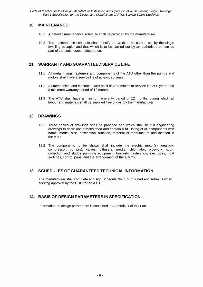
10. MAINTENANCE
10.1 A detailed maintenance schedule shall be provided by the manufacturer.
10.2 The maintenance schedule shall specify the work to be carried out by the single dwelling occupier and that which is to be carried out by an authorised person as part of the continuous maintenance.
11. WARRANTY AND GUARANTEED SERVICE LIFE
11.1 All metal fittings, fasteners and components of the ATU other than the pumps and
motors shall have a service life of at least 20 years.
11.2 All mechanical and electrical parts shall have a minimum service life of 5 years and a minimum warranty period of 12 months.
11.3 The ATU shall have a minimum warranty period of 12 months during which all
labour and materials shall be supplied free of cost by the manufacturer. 12. DRAWINGS
12.1 Three copies of drawings shall be provided and which shall be full engineering
drawings to scale and dimensioned and contain a full listing of all components with name, model, size, description, function, material of manufacture and location in the ATU.
12.2 The components to be shown shall include the electric motor(s), gearbox,
compressor, pump(s), valves, diffusers, media, chlorinator, pipework, scum collection and sludge pumping equipment, brackets, fastenings, electrodes, float switches, control panel and the arrangement of the alarms.
13. SCHEDULES OF GUARANTEED TECHNICAL INFORMATION
The manufacturer shall complete and sign Schedule No. 1 of this Part and submit it when seeking approval by the CHO for an ATU.
14. BASIS OF DESIGN PARAMETERS IN SPECIFICATION
Information on design parameters is contained in Appendix 1 of this Part.
Code of Practice for the Design Manufacture Installation and Operation of ATUs Serving Single Dwellings
Part 1 Specification for the Design and Manufacture of ATUs Serving Single Dwellings
- 10 -
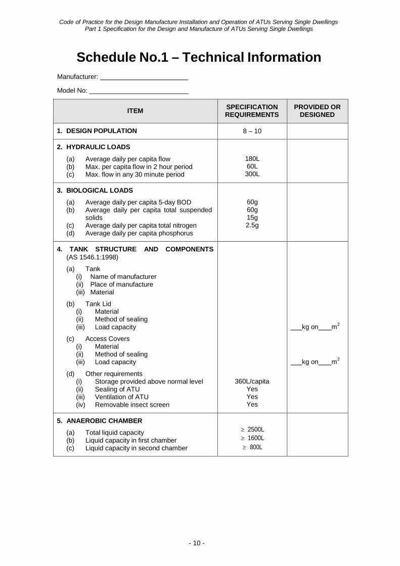
Schedule No.1 – Technical Information Manufacturer:
Model No:
ITEM SPECIFICATION REQUIREMENTS
PROVIDED OR DESIGNED
1. DESIGN POPULATION 8 – 10
2. HYDRAULIC LOADS
(a) Average daily per capita flow (b) Max. per capita flow in 2 hour period (c) Max. flow in any 30 minute period
180L 60L 300L
3. BIOLOGICAL LOADS
(a) Average daily per capita 5-day BOD (b) Average daily per capita total suspended
solids (c) Average daily per capita total nitrogen (d) Average daily per capita phosphorus
60g 60g 15g 2.5g
4. TANK STRUCTURE AND COMPONENTS (AS 1546.1:1998)
(a) Tank (i) Name of manufacturer (ii) Place of manufacture (iii) Material
(b) Tank Lid (i) Material (ii) Method of sealing (iii) Load capacity
(c) Access Covers (i) Material (ii) Method of sealing (iii) Load capacity
(d) Other requirements (i) Storage provided above normal level (ii) Sealing of ATU (iii) Ventilation of ATU (iv) Removable insect screen
360L/capita Yes Yes Yes
kg on m2
kg on m2
5. ANAEROBIC CHAMBER
(a) Total liquid capacity (b) Liquid capacity in first chamber (c) Liquid capacity in second chamber
≥ 2500L ≥ 1600L ≥ 800L
Code of Practice for the Design Manufacture Installation and Operation of ATUs Serving Single Dwellings
Part 1 Specification for the Design and Manufacture of ATUs Serving Single Dwellings
- 11 -
ITEM SPECIFICATION REQUIREMENTS
PROVIDED OR DESIGNED
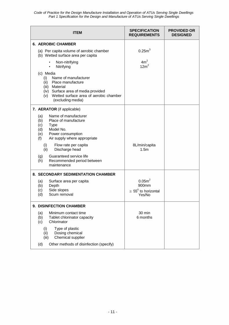
6. AEROBIC CHAMBER
(a) Per capita volume of aerobic chamber (b) Wetted surface area per capita
• Non-nitrifying • Nitrifying
(c) Media (i) Name of manufacturer (ii) Place manufacture (iii) Material (iv) Surface area of media provided (v) Wetted surface area of aerobic chamber
(excluding media)
0.25m3
4m2
12m2
7. AERATOR (if applicable)
(a) Name of manufacturer (b) Place of manufacture (c) Type (d) Model No. (e) Power consumption (f) Air supply where appropriate
(i) Flow rate per capita (ii) Discharge head
(g) Guaranteed service life (h) Recommended period between
maintenance
8L/min/capita 1.5m
8. SECONDARY SEDIMENTATION CHAMBER
(a) Surface area per capita (b) Depth (c) Side slopes (d) Scum removal
0.05m2
900mm ≥ 550 to horizontal
Yes/No
9. DISINFECTION CHAMBER
(a) Minimum contact time (b) Tablet chlorinator capacity (c) Chlorinator
(i) Type of plastic (ii) Dosing chemical (iii) Chemical supplier
(d) Other methods of disinfection (specify)
30 min 6 months
Code of Practice for the Design Manufacture Installation and Operation of ATUs Serving Single Dwellings
Part 1 Specification for the Design and Manufacture of ATUs Serving Single Dwellings
- 12 -
ITEM SPECIFICATION REQUIREMENTS
PROVIDED OR DESIGNED
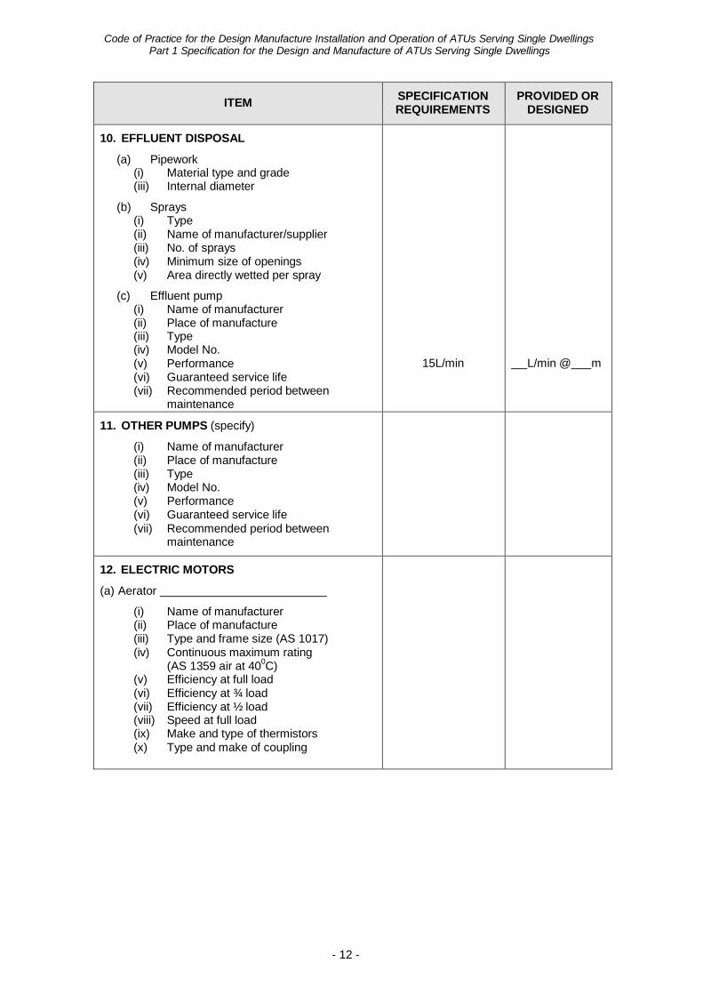
10. EFFLUENT DISPOSAL
(a) Pipework (i) Material type and grade (iii) Internal diameter
(b) Sprays (i) Type (ii) Name of manufacturer/supplier (iii) No. of sprays (iv) Minimum size of openings (v) Area directly wetted per spray
(c) Effluent pump (i) Name of manufacturer (ii) Place of manufacture (iii) Type (iv) Model No. (v) Performance (vi) Guaranteed service life (vii) Recommended period between
maintenance
15L/min
L/min @ m
11. OTHER PUMPS (specify)
(i) Name of manufacturer (ii) Place of manufacture (iii) Type (iv) Model No. (v) Performance (vi) Guaranteed service life (vii) Recommended period between
maintenance
12. ELECTRIC MOTORS
(a) Aerator
(i) Name of manufacturer (ii) Place of manufacture (iii) Type and frame size (AS 1017) (iv) Continuous maximum rating
(AS 1359 air at 400C) (v) Efficiency at full load (vi) Efficiency at ¾ load (vii) Efficiency at ½ load (viii) Speed at full load (ix) Make and type of thermistors (x) Type and make of coupling
Code of Practice for the Design Manufacture Installation and Operation of ATUs Serving Single Dwellings
Part 1 Specification for the Design and Manufacture of ATUs Serving Single Dwellings
- 13 -
ITEM SPECIFICATION REQUIREMENTS
PROVIDED OR DESIGNED
12. ELECTRIC MOTORS cont….
(b) Effluent Pump
(i) Name of manufacturer (ii) Place of manufacture (iii) Type and frame size (AS 1017) (iv) Continuous maximum rating
(AS 1359 air at 400C) (v) Efficiency at full load (vi) Efficiency at ¾ load (vii) Efficiency at ½ load (viii) Speed at full load (ix) Make and type of thermistors (x) Type and make of coupling
(d) Other electric motors (specify)
(i) Name of manufacturer (ii) Place of manufacture (iii) Type and frame size (AS 1017) (iv) Continuous maximum rating
(AS 1359 air at 400C) (v) Efficiency at full load (vi) Efficiency at ¾ load (vii) Efficiency at ½ load (viii) Speed at full load (ix) Make and type of thermistors (x) Type and make of coupling
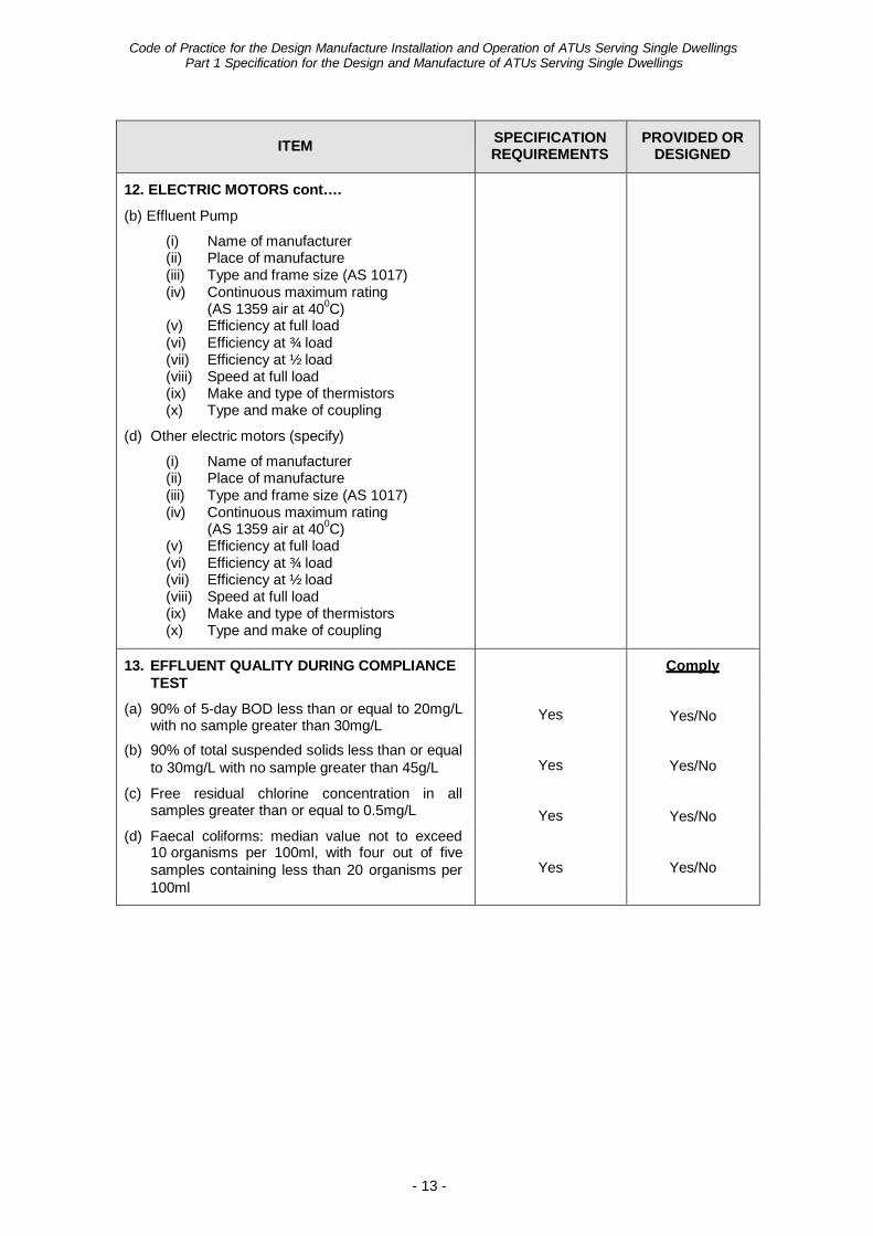
13. EFFLUENT QUALITY DURING COMPLIANCE
Yes
Comply TEST
(a) 90% of 5-day BOD less than or equal to 20mg/L with no sample greater than 30mg/L Yes/No
(b) 90% of total suspended solids less than or equal to 30mg/L with no sample greater than 45g/L Yes Yes/No
(c) Free residual chlorine concentration in all samples greater than or equal to 0.5mg/L Yes Yes/No
(d) Faecal coliforms: median value not to exceed 10 organisms per 100ml, with four out of five samples containing less than 20 organisms per Yes Yes/No 100ml
Code of Practice for the Design Manufacture Installation and Operation of ATUs Serving Single Dwellings
Part 1 Specification for the Design and Manufacture of ATUs Serving Single Dwellings
- 14 -
IN-H
OU
SE P
ER C
APIT
A W
ATER
U
SAG
E (L
/cd)
APPENDIX 1
Basis of Design Parameters in Specification 1. Part 1 of the Code specifies requirements for ATUs with the intent of providing effective
and reliable wastewater treatment over a long period of time. The design parameters specified have been derived from proven technology in the field of wastewater treatment. Capacities specified are minimum values and do not constrain manufacturers from providing additional capacity. By application of the specified design parameters and good field design and construction principles, the compliance criteria should be met.
2. Specific Design Requirements.
Part 1 Clause 3.2 The upper limit for ATUs serving single dwellings covered by Part 1 of
the Code has been set as ten persons as larger systems may require different criteria and should be considered separately.
Part 1 Clause 3.3 The minimum allowable design capacity of 8 persons has been
adopted to be consistent with the Regulations which require that the minimum allowable design capacity for a septic tank serving a single dwelling be 8 persons.
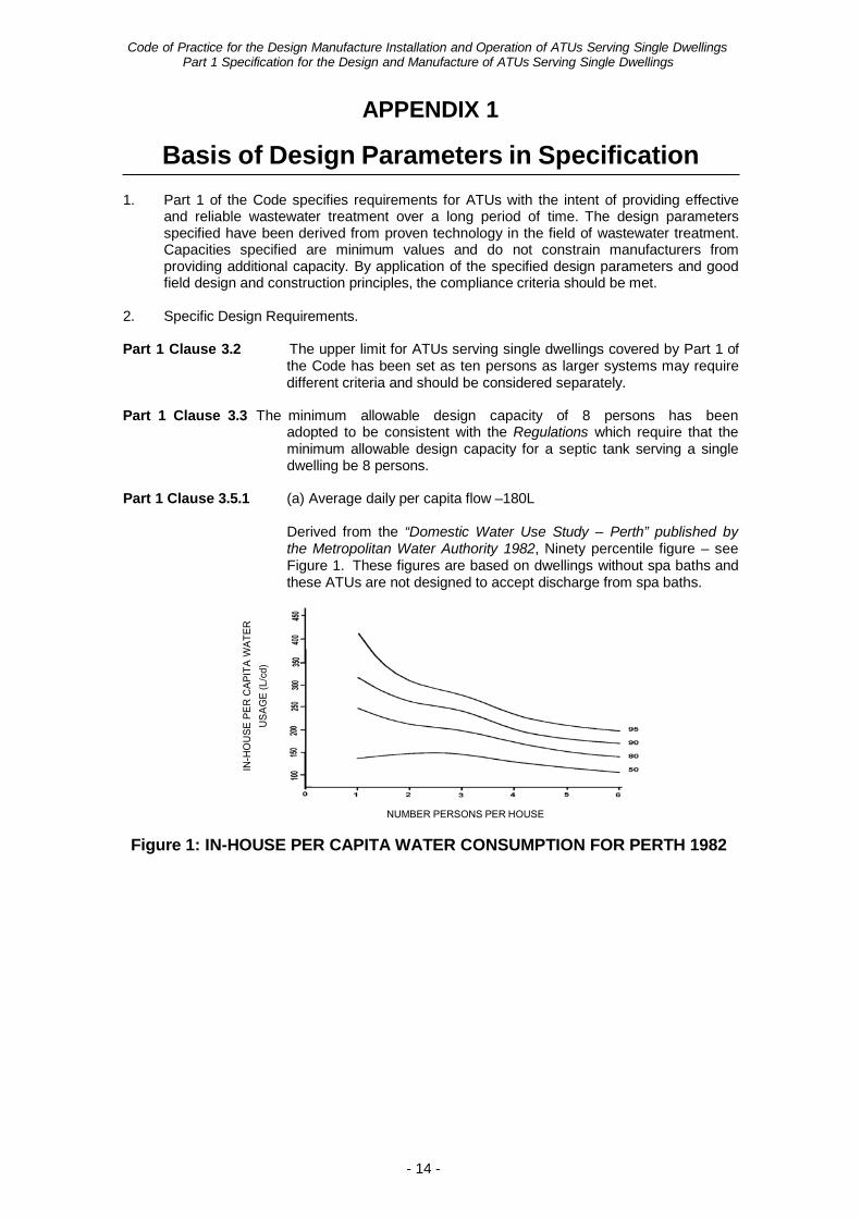
Part 1 Clause 3.5.1 (a) Average daily per capita flow –180L
Derived from the “Domestic Water Use Study – Perth” published by the Metropolitan Water Authority 1982, Ninety percentile figure – see Figure 1. These figures are based on dwellings without spa baths and these ATUs are not designed to accept discharge from spa baths.
NUMBER PERSONS PER HOUSE
Figure 1: IN-HOUSE PER CAPITA WATER CONSUMPTION FOR PERTH 1982
Code of Practice for the Design Manufacture Installation and Operation of ATUs Serving Single Dwellings
Part 1 Specification for the Design and Manufacture of ATUs Serving Single Dwellings
- 15 -
Part 1 Clause 3.5.1 (b) Maximum per capita flow during any two hourly period – 60L
Assuming one-third of average daily per capital flow down in two hours.
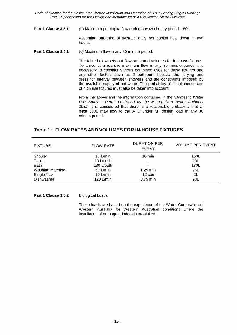
Part 1 Clause 3.5.1 (c) Maximum flow in any 30 minute period.
The table below sets out flow rates and volumes for in-house fixtures. To arrive at a realistic maximum flow in any 30 minute period it is necessary to consider various combined uses for these fixtures and any other factors such as 2 bathroom houses, the “drying and dressing” interval between showers and the constraints imposed by the available supply of hot water. The probability of simultaneous use of high use fixtures must also be taken into account.
From the above and the information contained in the “Domestic Water Use Study – Perth” published by the Metropolitan Water Authority 1982, it is considered that there is a reasonable probability that at least 300L may flow to the ATU under full design load in any 30 minute period.
Table 1: FLOW RATES AND VOLUMES FOR IN-HOUSE FIXTURES
FIXTURE FLOW RATE DURATION PER EVENT
VOLUME PER EVENT
Shower 15 L/min 10 min 150L Toilet 10 L/flush - 10L Bath 130 L/bath - 130L Washing Machine 60 L/min 1.25 min 75L Single Tap 10 L/min 12 sec 2L Dishwasher 120 L/min 0.75 min 90L
Part 1 Clause 3.5.2 Biological Loads
These loads are based on the experience of the Water Corporation of Western Australia for Western Australian conditions where the installation of garbage grinders in prohibited.
Code of Practice for the Design Manufacture Installation and Operation of ATUs Serving Single Dwellings
Part 1 Specification for the Design and Manufacture of ATUs Serving Single Dwellings
- 16 -
Part 1 Clause 4.1 Anaerobic Chamber 2500L
The Regulations stipulate that the minimum capacity for a septic tank followed by soil adsorption systems shall be 3180L. For ATUs where the septic tanks are followed by an attached growth, biological process, 2500L is considered to be adequate to provide primary treatment.
Two compartment septic tank: 1600L minimum in first chamber; 800L minimum in the second chamber.
Research has shown that two compartment septic tanks perform better than single tank septic tanks. The minimum volumes in each compartment have been set to ensure an appropriate two-thirds, one-third distribution where the minimum capacity is provided. This distribution has been found from experience to produce good results.
Part 1 Clause 4.2.3.1 Minimum volume in the aerobic chamber of 0.25m3 per capita.
The size of the aerobic chamber is based on a volumetric loading of 0.2kg 5-day BOD/m3/d assuming 20% BOD removal in the anaerobic chamber. This empirical criteria has been widely applied to many different aerobic processes including trickling filters, activated sludge and submerged aerated filters. This low loading rate will ensure a low rate process of high reliability and consistent effluent quality.
Part 1 Clause 4.2.3.2 Minimum wetted surface area in the aerobic chamber of 4m2 per
capita for non-nitrifying systems and 12m2 per capita for nitrifying systems.
This criteria is based on the total wetted surface area in the aerobic chamber (walls, floor, baffles, media, etc) as all wetted surfaces are capable of supporting biological growth responsible for the purification of wastewater. Most ATUs will be designed to operate in a non- nitrifying mode although the requirements for the non-nitrifying mode although the requirements for nitrification are also included. Nitrifying ATUs arguably achieve more reliable disinfection when chlorination is employed.
4m2 per capita for non-nitrifying systems – based on 5-day BOD loading of 12g/m2/d (assuming 20% 5-day BOD removal in the anaerobic chamber). This loading rate has been proven to be adequate for 5-day BOD removal in attached growth, aerobic systems.
12m2 per capita for nitrifying systems – based on a 5-day BOD loading of 4g/m2/d and a nitrogen loading of 1g/m2/d (assuming 20% 5-day BOD and nitrogen removal in the anaerobic chamber). These loading rates have been proven to be adequate to ensure nitrification in attached growth aerobic systems.
Part 1 Clause 4.2.4.1 Air supply of 8L/min/capita at 1.5m hydrostatic head.
Based on – (i) 20% 5-day removal in anaerobic chamber. (ii) No nitrification. (iii) 1.3g O2/g of 5-day BOD. (iv) Oxygen transfer efficiency of 2%.
Code of Practice for the Design Manufacture Installation and Operation of ATUs Serving Single Dwellings
Part 1 Specification for the Design and Manufacture of ATUs Serving Single Dwellings
- 17 -
Part 1 Clause 4.2.4.3 Maintain 2mg/L of dissolved oxygen in aerobic chamber under & 4.2.5.1 maximum 2 hourly flow.
The minimum dissolved oxygen concentration necessary to ensure that the biological slimes remain aerobic and that the purification processes are not oxygen limited is widely recognised as 2mg/L.
Part 1 Clause 4.3.2 Minimum surface area of 0.05m2/capita and minimum depth of
900 mm.
The surface area of 0.05m2/capita will ensure that the upflow velocity does not exceed 0.6m/hr at the maximum 2 hourly flow rate and 1.2-1.5m/hr (8-10 persons) at the maximum 30 minute flow rate. These upflow velocities will ensure good solids – liquid separation in the secondary sedimentation chamber and a consistently good effluent.
The minimum depth of 900mm in combination with the surface area requirements provides 1.5 hours detention at the maximum 2 hourly flow rate and 0.6 – 0.75 hours (8-10 persons) at the maximum 30 minute flow rate. These detention times should be adequate for the flocculation of biological solids.
Part 1 Clause 4.4.1 Separate disinfection chamber.
To ensure that adequate contact time is provided under all flow conditions, a separate disinfection chamber has been required. A combination disinfection and pumping chamber is not permitted.
Part 1 Clause 4.4.1 0.5mg/L free chlorine residual after 30 minutes. & 4.4.3
This is a widely used and well proven criteria which ensures a high level of disinfection with secondary treated wastewater.
Part 1 Clause 4.5.1.3 Effluent pump rate to be at least 50% greater than maximum
30 minute flow rate.
This is to ensure an ample factor of safety exists in the effluent disposal system to cater for greater than anticipated inflow rates.
Part 1 Clause 5.6 2 days storage above normal operating level.
This has been specified to enable adequate time to respond to faults and takes consideration of the fact that the Specification applies to the whole of Western Australia and the difficulty in responding more quickly in non-metropolitan areas.
Part 1 Clause 9.7.4 Compliance Criteria for Faecal Contamination.
These are set down in the National Water Quality Management Strategy – “Guidelines for Sewerage Systems – Use of Reclaimed Water, November 2000”, published by the Agriculture and Resource Management Council of Australia and New Zealand et al.
Due to reuse of water taking place in household gardens under largely unsupervised conditions, the standard recommended for the spray irrigation of salad crops by the National Water Quality Management Strategy – “Guidelines for Sewerage Systems – Use of Reclaimed Water, November 2000”, published by the Agriculture and Resource Management Council of Australia and New Zealand et al has been adopted.
Code of Practice for the Design Manufacture Installation and Operation of ATUs Serving Single Dwellings
Part 1 Specification for the Design and Manufacture of ATUs Serving Single Dwellings
- 18 -
APPENDIX 2 (Clause 9.2)
Test Procedure
1. COMMISSIONING
The ATU shall be assembled, installed and filled in accordance with the manufacturer’s instructions. The manufacturer shall inspect the system for proper installation. If no defects are detected and the system is judged to be structurally sound, it shall be placed in operation in accordance with the manufacturer’s start-up procedures.
2. RAW INFLUENT
The flow rate of the raw influent to the ATU shall be capable of being measured and automatically logged.
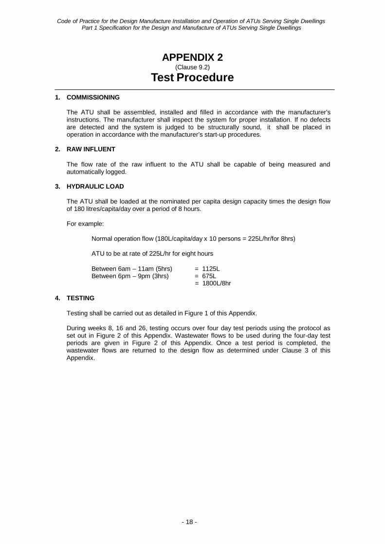
3. HYDRAULIC LOAD
The ATU shall be loaded at the nominated per capita design capacity times the design flow of 180 litres/capita/day over a period of 8 hours.
For example:
Normal operation flow (180L/capita/day x 10 persons = 225L/hr/for 8hrs)
ATU to be at rate of 225L/hr for eight hours
Between 6am – 11am (5hrs) = 1125L Between 6pm – 9pm (3hrs) = 675L
= 1800L/8hr
4. TESTING
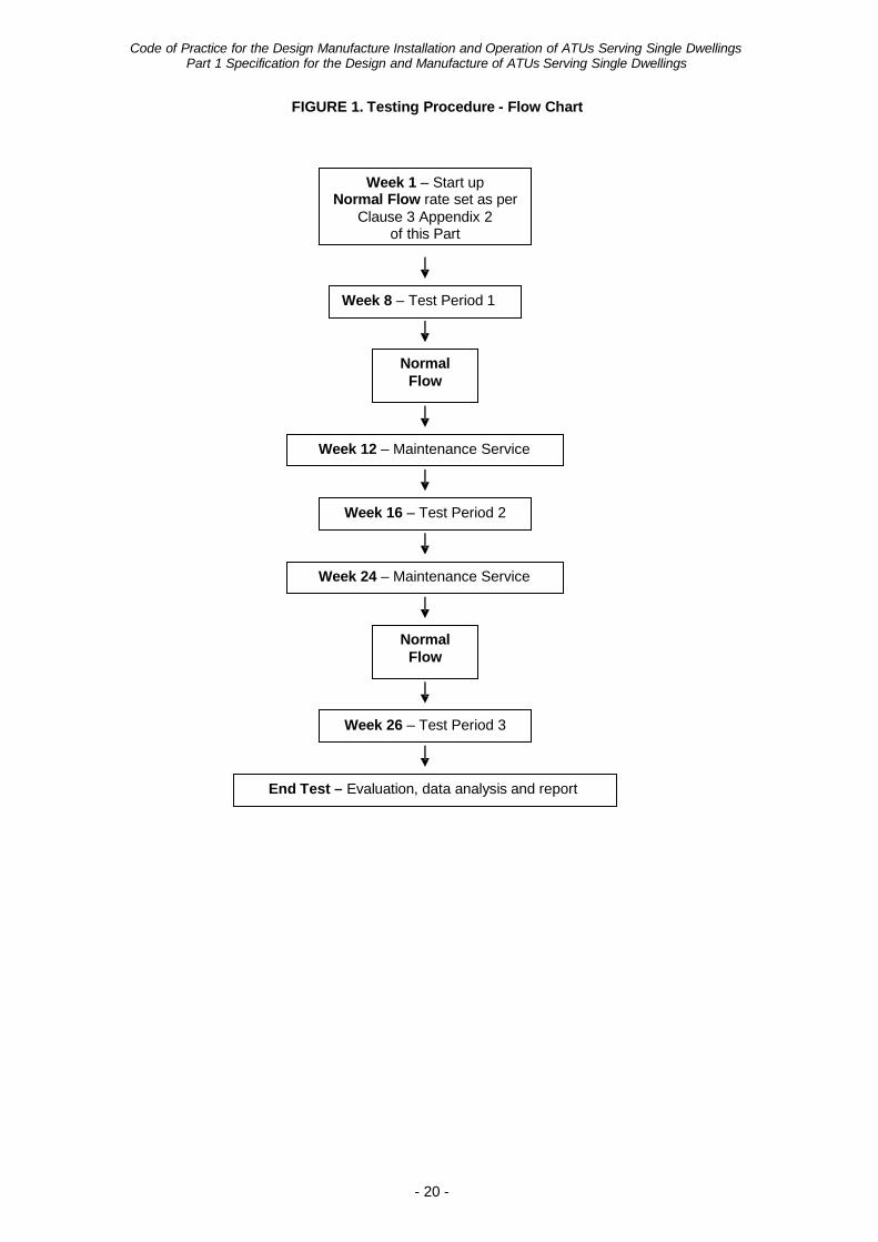
Testing shall be carried out as detailed in Figure 1 of this Appendix.
During weeks 8, 16 and 26, testing occurs over four day test periods using the protocol as set out in Figure 2 of this Appendix. Wastewater flows to be used during the four-day test periods are given in Figure 2 of this Appendix. Once a test period is completed, the wastewater flows are returned to the design flow as determined under Clause 3 of this Appendix.
Code of Practice for the Design Manufacture Installation and Operation of ATUs Serving Single Dwellings
Part 1 Specification for the Design and Manufacture of ATUs Serving Single Dwellings
- 19 -
5. TESTS
The tests required are as follows:
• Raw wastewater: BOD5, SS.
• During test period: BOD5, SS, thermotolerant coliforms, dissolved oxygen, disinfectant levels (where applicable), nutrient levels - total N and total P (where applicable), temperature - ambient and in aeration chamber.
6. SAMPLING
The sampling points are as follows:
• Samples for BOD5 and SS shall be taken prior to disinfection.
• The final effluent samples for thermotolerant coliforms, disinfectant levels (where applicable) and nutrient levels (where applicable) shall be taken from the outlet of the disinfection chamber.
• Samples for dissolved oxygen shall be taken from the aeration chamber.
The samples for BOD5, SS, total nitrogen, total N, total P and thermotolerant coliforms shall be analysed by a laboratory registered by the National Association of Testing Authorities or a laboratory recognised by the CHO to carry out analyses for the parameters specified.
7. MAINTENANCE SERVICING
During weeks 12 and 24 a maintenance service is to be performed in accordance with the manufacturer’s procedure.
8. REPORT
An evaluation report shall be prepared based on the design criteria, construction requirements and test criteria with particular reference to:
• Identification of the type and model of the ATU tested, compliance with drawings, rated
capacity, loadings and testing methods.
• A log of tests, compliance calculations, maintenance, equipment or component failures and other factors pertinent to the test evaluation.
• Date of test.
• Analytical test results.
Code of Practice for the Design Manufacture Installation and Operation of ATUs Serving Single Dwellings
Part 1 Specification for the Design and Manufacture of ATUs Serving Single Dwellings
- 20 -
FIGURE 1. Testing Procedure - Flow Chart
Week 1 – Start up Normal Flow rate set as per
Clause 3 Appendix 2 of this Part
Week 8 – Test Period 1
Normal Flow
Week 12 – Maintenance Service
Week 16 – Test Period 2
Week 24 – Maintenance Service
Normal Flow
Week 26 – Test Period 3
End Test – Evaluation, data analysis and report
Code of Practice for the Design Manufacture Installation and Operation of ATUs Serving Single Dwellings
Part 1 Specification for the Design and Manufacture of ATUs Serving Single Dwellings
- 21 -
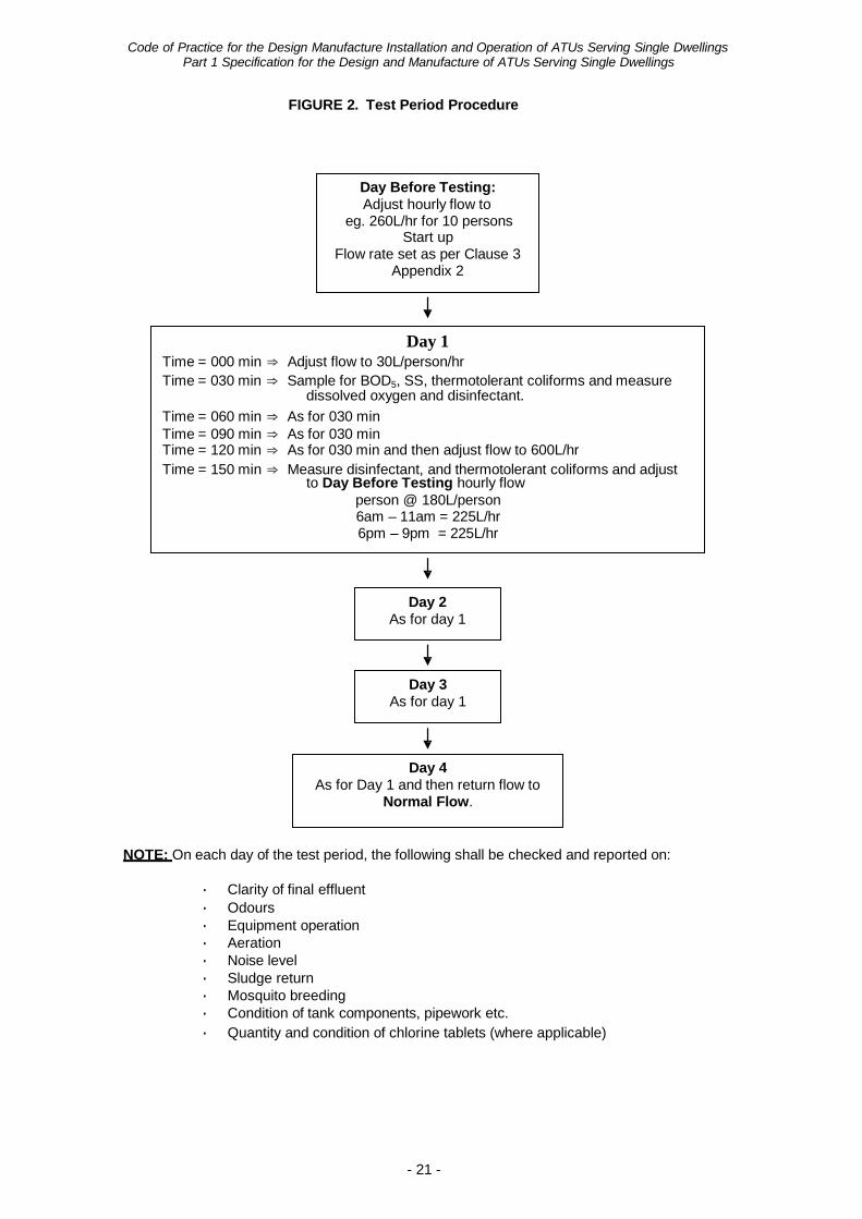
FIGURE 2. Test Period Procedure
Day Before Testing: Adjust hourly flow to
eg. 260L/hr for 10 persons Start up
Flow rate set as per Clause 3 Appendix 2
Day 1 Time = 000 min ⇒ Adjust flow to 30L/person/hr Time = 030 min ⇒ Sample for BOD5, SS, thermotolerant coliforms and measure
dissolved oxygen and disinfectant. Time = 060 min ⇒ As for 030 min Time = 090 min ⇒ As for 030 min Time = 120 min ⇒ As for 030 min and then adjust flow to 600L/hr Time = 150 min ⇒ Measure disinfectant, and thermotolerant coliforms and adjust
to Day Before Testing hourly flow person @ 180L/person 6am – 11am = 225L/hr 6pm – 9pm = 225L/hr
Day 2 As for day 1
Day 3 As for day 1
Day 4 As for Day 1 and then return flow to
Normal Flow.
NOTE: On each day of the test period, the following shall be checked and reported on:
• Clarity of final effluent • Odours • Equipment operation • Aeration • Noise level • Sludge return • Mosquito breeding • Condition of tank components, pipework etc. • Quantity and condition of chlorine tablets (where applicable)
Code of Practice for the Design Manufacture Installation and Operation of ATUs Serving Single Dwellings
22
PART 2
INSTALLATION AND OPERATION OF
AEROBIC TREATMENT UNITS (ATUs)
SERVING SINGLE DWELLINGS
The Department of Health acknowledges the South Australian Health Commission for their kind permission to publish, with modification, parts of the “Standard for the Installation and Operation of Septic Tank Systems in South Australia, Supplement B – Aerobic Wastewater Treatment Systems” (1990) in the development of Part 2 of the Code.
Code of Practice for the Design Manufacture Installation and Operation of ATUs Serving Single Dwellings
Part 2 Installation and Operation of ATUs Serving Single Dwellings
- 23 -
1. SCOPE
Part 2 of the Code sets out the requirements for the installation, operation and maintenance of ATUs serving single dwellings.
Installations will not be approved in locations or circumstances, which are contrary to the Government Sewerage Policiy, Perth Metropolitan Region and the Country Sewerage Policy. For example, they cannot be used as a means of achieving subdivision of land contrary to the Policies.
Each unit in a duplex development is to be serviced by an individual ATU.
The irrigation area serving an ATU is an integral part of the system and must be installed by the person responsible for installing the ATU.
2. INTRODUCTION
The demand for the use of individual aerobic wastewater treatment systems has occurred through changes in wastewater technology; development within areas where conventional subsoil effluent disposal methods are ineffective; the need to conserve water resources and to protect the environment.
ATUs can comprise a two chamber septic tank, an aeration chamber, a clarification chamber, a disinfection chamber and a pump chamber from which the resultant reclaimed effluent is discharged to a dedicated irrigation disposal area (either above or below ground).
Additional fixtures such as spa baths and food waste disposal units are not permitted to be used in conjunction with ATUs.
As ATUs rely on aeration and in many instances chlorination to treat the effluent, they require REGULAR MAINTENANCE to ensure that the reclaimed effluent satisfies the following criteria:-
• BOD5 – less than 20 mg/litre • Suspended Solids - less than 30 mg/litre • Free Residual Chlorine - a minimum of 0.5 mg/litre • Faecal Coliforms - not more than 10 per 100 ml
ATUs require a minimum 250 m² of land (minimum of 150 m² for the disposal area plus a minimum of 100 m² for social and recreational areas) except where a reduced irrigation area meeting the requirement under Clause 4(b) of this Part can be met. This area is additional to any space required for the residence, sheds, carports, driveways, access paving and setback distances.
Although the chlorinated reclaimed effluent is of a standard suitable for irrigation, there must be at least two signs erected in the surface irrigation disposal area warning that reclaimed effluent is being used and is unfit for drinking.
Code of Practice for the Design Manufacture Installation and Operation of ATUs Serving Single Dwellings
Part 2 Installation and Operation of ATUs Serving Single Dwellings
- 24 -
3. SYSTEM APPROVAL
ATUs must be designed and manufactured in accordance with Part 1 of the Code.
As a condition of approval under the Code, the manufacturer is also required to supply the owner/occupier of the premises with a manual setting out the care, operation and maintenance of the system, including procedures to follow in the event of a system malfunction.
(a) Legislation
The Health Act (Miscellaneous Provisions) 1911 requires that sewage and sullage wastes must be collected, treated and disposed of so as to prevent risk to health.
Under the Health Act (Miscellaneous Provisions) 1911, approval is required from the local government or the CHO to install a septic tank/ATU.
• In the case of a septic tank/ATU designed to serve a single dwelling or any
other building that produces not more than 540 litres of sewage per day, approval must be obtained from local government under Regulation 4 of the Regulations.
• In the case of a septic tank/ATU designed to serve other than a single dwelling
or any other building that produced more than 540 litres per day, approval must be obtained from the CHO under Regulation 4(a) of the Regulations.
Approval under the Regulations to construct or install an apparatus for the treatment of sewage must first be obtained before beginning any work associated with the installation of any plumbing, drains, septic tanks/ATUs.
Persons having the work undertaken on their behalf, or the tradesperson carrying out the installation, must submit details of the proposed system in an application to the relevant approving body (Local Government or the CHO as the case requires) and receive approval before any work begins.
(b) Applications
An application seeking approval to install an ATU must be made on the ‘Application to Construct or Install an Apparatus for the Treatment of Sewage’ form. The application must be accompanied by the scheduled fees as outlined in Schedule 1 of the Regulations.
Code of Practice for the Design Manufacture Installation and Operation of ATUs Serving Single Dwellings
Part 2 Installation and Operation of ATUs Serving Single Dwellings
- 25 -
In addition to completing the relevant application form, and submitting the scheduled fees, the following information must also be provided:
• type of system to be installed
• manufacturer's name
• model number
• capacity
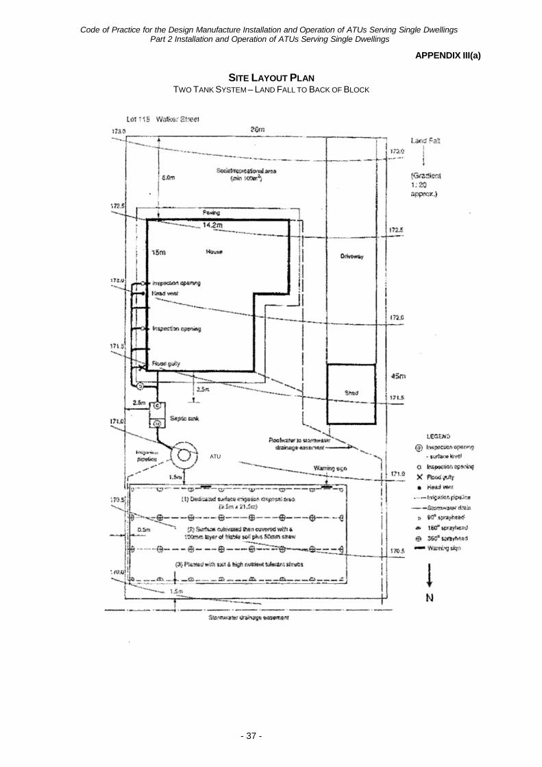
• a detailed site layout plan (in duplicate or triplicate as the case requires) drawn to a scale of 1 in 100 showing:
- block dimensions
- contours indicating natural ground fall, wells, bores, dams, watercourses
and depth to groundwater.
- proposed location of the building and all other structures including sheds, swimming pools and paving.
- details of any site modifications e.g. benching, cutting and filling.
- details and location of any diversion trenches to collect surface or migrating
subsurface water.
- details and location of roof water disposal.
- proposed location of the septic tank/ATU and surface irrigation disposal area.
- setback distances from boundaries, buildings, septic tank/ATU, surface
irrigation disposal area and other structures and buildings on the boundary alignment (see Appendix III of this Part).
• details of the treatment disposal system including:
- position of irrigation lines.
- information as to the location of irrigation discharge points.
- method of construction of surface irrigation disposal area bed, including the
materials to be used.
- number and location of plants or shrubs in the irrigation area. (See Appendix I of this Part for a list of suitable plants and shrubs)
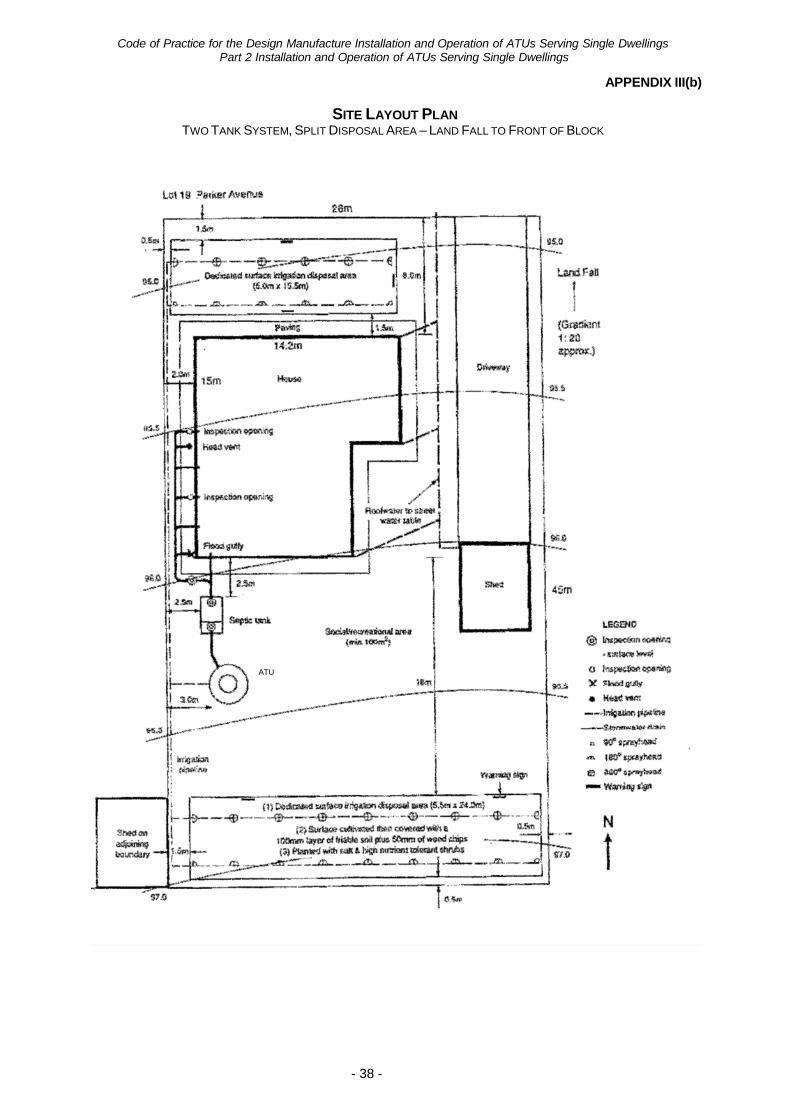
- where a split irrigation system is used; details of mechanisms to ensure an
even discharge to each area and to prevent overloading of individual areas.
• a detailed house layout plan (in duplicate or triplicate as the case requires)
drawn to a scale of 1 in 100, showing reference to plumbing details as required by the Regulations.
• The application, inspection and (if required) local government report fees - as
currently prescribed.
Failure to supply all requested information will delay approval of the application.
Code of Practice for the Design Manufacture Installation and Operation of ATUs Serving Single Dwellings
Part 2 Installation and Operation of ATUs Serving Single Dwellings
- 26 -
4. SURFACE IRRIGATION
(a) Disposal Area
A minimum of 150 m2 is required for surface irrigation and the irrigation area shall not be divided into more than two separate areas.
The disposal area shall maintain at least 300 mm of permeable soil above an underlying limiting layer eg rock or hard pan. At all times the disposal area shall be maintained over its entire surface area with 100 mm of friable soil and a 50mm top cover of mulching material (pine bark etc).
The planting of any form of food crop/fruit trees etc is not permitted within the irrigation area.
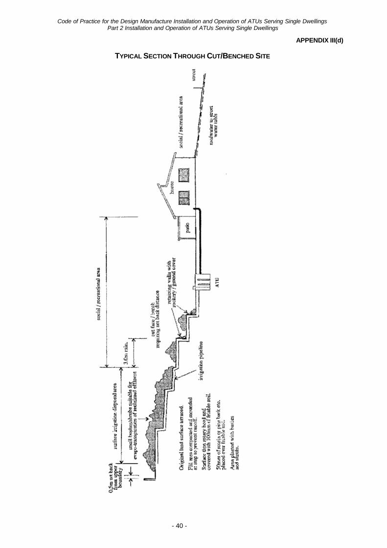
Where the land gradient is greater than 1:10 and it is practicable, the surface irrigation disposal area may need to be modified by benching or bunding etc and/or increased in size to enable satisfactory disposal of the reclaimed wastewater.
If the land gradient is greater than 1:5 then the application will be individually assessed.
The disposal area is not to be located on land prone to waterlogging or subject to floodwater inundation.
Except for maintenance purposes, pedestrian traffic should be excluded from the surface irrigation disposal area.
Within the surface irrigation disposal area there must be at least two warning signs clearly positioned to inform the occupants of the premises that reclaimed effluent is used for irrigation. These signs must be on a white background with RED lettering of at least 20 mm in height and worded as follows:-
WARNING – RECLAIMED EFFLUENT
NOT SUITABLE FOR HUMAN CONTACT/CONSUMPTION
(b) Reduced irrigation areas for sand conditions
Installation of reduced irrigation areas will only be permitted in sandy type soil in circumstances which satisfy the following:
(i) For the purpose of determining a sandy soil the soils classified as LS1,
LS5, S6, S8, D9, S10, S12 or similar on Mines Department Environmental Geology Series maps are considered to generally satisfy the criteria as a sandy soil. However, aberrations to site specific locations can be expected and these must be considered when dealing with each application.
(ii) The site must have adequate clearance to groundwater i.e. the post
development level must be not less than 1.8 metres above the highest expected water table with a pre-development clearance of not less than 1.2 metres to the highest expected water table.
(iii) In submitting an application the applicant must submit details on (a)
and (b) with the application.
The reduced areas apply only to single dwelling units and are:
2 bedroom dwelling - 60 square metres 3 bedroom dwelling - 80 square metres 4 bedroom dwelling - 90 square metres
Code of Practice for the Design Manufacture Installation and Operation of ATUs Serving Single Dwellings
Part 2 Installation and Operation of ATUs Serving Single Dwellings
- 27 -
For single residential development, soil amendment is not required in the irrigation area, unless required in environmentally sensitive areas. (See paragraph (e)(ii) of this Clause)
Density development in constrained areas within the inner metropolitan area, as defined by the Government Sewerage Policy, Perth Metropolitan Region, must maintain the 30 cubic metres of the approved amended soil mix in the irrigation area. (See paragraph (e) of this Clause)
(c) Landscaping
The disposal area shall be landscaped to prevent pooling of effluent or run-off from the area.
An adequate number of plants, suitable for the transpiration of reclaimed effluent and salt and nutrient tolerant (see Appendix I of this Part) shall be planted over the disposal area.
All landscaping and the provision of friable soil, mulching material and plants shall be completed when the ATU is commissioned for use or within 30 days of occupancy of the premises.
Where the effluent flow is low additional watering of the disposal field may be necessary to maintain plant growth.
(d) Irrigation System
The reclaimed effluent must be evenly distributed over the entire disposal area without spray drift, pooling and/or run-off from the area.
All materials, piping and fittings etc, used for effluent disposal shall be in accordance with Clause 4.5 of Part 1 of the Code.
Care must be taken in the selection of the type and placement of the spray heads to ensure the plume is contained totally within the surface disposal area. This may require the installation of 90° and/or 180° sprays around the perimeter of the irrigation disposal area.
The use of UPVC potable water pipes is not permitted under any circumstances.
The surface irrigation disposal system must not be capable of connection to the reticulated water supply. For public health reasons the use of garden hoses and fittings are strictly not permitted under any circumstances.
Irrigation pipes are required to be fixed and buried at least 150 mm below the surface.
All roof waters must be diverted away from the surface irrigation system disposal area.
Where necessary the irrigation disposal area should be bunded to prevent irrigation water run-off.
Code of Practice for the Design Manufacture Installation and Operation of ATUs Serving Single Dwellings
Part 2 Installation and Operation of ATUs Serving Single Dwellings
- 28 -
(e) Phosphorus Retention
Release of phosphorus from wastewater does give rise to environmental pollution and in several situations minimising phosphorous movement from a site is necessary. In such situations an amended soil system must be incorporated into the irrigation area.
An amended soil system limiting phosphorus discharge will be required on ATUs in the following situations.
(i) Density developments in constrained areas within the inner metropolitan
area that satisfy the requirements of Section 5.1 of the Government Sewerage Policy, Perth Metropolitan Region.
(ii) Areas where there are environmental constraints on the use of conventional
on-site disposal systems.
The design of a soil amendment system for surface irrigation must be approved by the CHO prior to any application to install an ATU in any of the situations specified in paragraph (e)(i) and (e)(ii) of this Clause. The minimum amount of amended soil shall not be less than 30 cubic metres in the irrigation area.
Phosphorus Retention Index (PRI) can be defined as the ratio of phosphorus absorbed, to the phosphorus remaining when soil is left in contact with a standard phosphorus solution under standard conditions.
Irrigation areas need to contain soils which have a PRI of greater than 20. Sampling of soil for PRI analysis should be carried out initially at the time of installation, and then 3 yearly. If the PRI for the existing soil at the time of installation is below 20 then a high PRI amended soil will be required for the site; e.g. gypsum treated red mud.
Where it is demonstrated by soil testing that the existing soil contains a PRI greater than 20, it is not necessary to add soil amendment.
If the PRI falls below 5 during any three year period, more soil amendment will be required.
Soil to a depth of a 150 mm will be required as a minimum, once it has satisfied PRI requirements (i.e. greater than 20), and an overall depth to an impermeable layer of 300 mm.
Sampling of soil for PRI analysis should be over the soil depth intended for amendment (usually 1 metre) and should include a number of cores over the area which are bulked into one sample for analysis. For heavy (suspected high PRI soils) soil cores should be taken to at least 500 mm depth.
Responsibility for conducting PRI testing shall rest with the titleholder/owner.
5. SUB-SOIL DISPOSAL SYSTEM
Wastewater may be disposed of into a sub-soil disposal system. However, where such a system is not a conventional approved system, the design must first be submitted to and approved by the CHO before any such system is used with an ATU. The chlorination of the wastewater in a sub-soil disposal system may not be required.
Code of Practice for the Design Manufacture Installation and Operation of ATUs Serving Single Dwellings
Part 2 Installation and Operation of ATUs Serving Single Dwellings
- 29 -
6. ALLOTMENT REQUIREMENTS
In addition to the area required for buildings, paving, access (foot and vehicle), vehicle parking and the surface irrigation disposal area, the site needs to be large enough to provide non contact areas such as those mentioned above and the following:
(a) Recreational/Social Area
Sufficient space must be provided on the site for social and recreational activities. For single residential occupancies this must be at least 100 m².
NOTE: The recreational area does not include access paving, driveways, sheds,
carports etc.
(b) Set Back Distances
To protect buildings, structures and adjoining properties, a range of minimum set back distances are necessary:
Surface Irrigation Disposal Area
On a flat or gently sloping site:
• A minimum of 1.8 metres from boundaries with open fencing. Where fencing is closed (i.e. fibrous cement, brick etc.) and has a minimum height of 1.2 metres, then the minimum distance may be closer to the boundary as determined by the local government.
• 1.8 metres from buildings, including those erected on adjoining allotments.
• 1.8 metres from any paved surface including driveways, paths etc.
On a sloping site:
• A minimum of 1.8 metres from boundaries with open fencing. Where fencing is closed (i.e. fibrous cement, brick etc.) and has a minimum height of 1.2 metres, then the minimum distance may be closer to the boundary as determined by the local government.
• 1.8 metres from any paved surface including driveways, paths etc.
• 3.0 metres upslope from a lower cut face/bench.
• 3.0 metres upslope from buildings, including those erected on adjoining allotments.
From swimming pools:
• 3.0 metres on flat ground
• 3.0 metres downslope
• 6.0 metres upslope
From wells, bores, dams or water courses used or available for human or animal consumption, or a watercourse within a proclaimed water catchment area:
• 30 metres
Code of Practice for the Design Manufacture Installation and Operation of ATUs Serving Single Dwellings
Part 2 Installation and Operation of ATUs Serving Single Dwellings
- 30 -
An ATU must be a minimum of:
• 1.2 metres from any boundaries or buildings
• 1.8 metres from the surface irrigation disposal area
• 6.0 metres from a well, bore, dam or any water course whether it is used for a domestic water supply or discharging to a proclaimed water catchment area.
NOTE: Where it is intended to locate the surface irrigation disposal area upslope
of a building, the footing design engineer should be consulted to determine the likely impact on the building footing and the need for any additional requirements such as diversion trenches. Confirmation of the footing design engineer's requirements should be provided with the application.
(c) Depth to Groundwater
The minimum depth from the upper surface of the irrigation area to the highest known water table shall be 500 mm. In the case of a surface irrigation system, the 500 mm distance being from the upper surface of the irrigation area to the highest known water table level. For subsoil systems, the 500 mm is taken from the invert of the discharge pipe to the highest known water level. This is necessary to ensure a safety factor exists should there be a malfunction in the chlorination unit. Given that irrigation is above ground, a 500 mm zone of unsaturated soil is seen as the minimum acceptable distance to permit microbiological attenuation. For reduced irrigation areas in sand conditions, the clearance to ground water shall not be less than 1.8 m post development with a pre-development level of not less than 1.2 m to the highest expected water table.
7. SYSTEM OPERATION
To ensure that the operation of the treatment unit is efficient and trouble-free, the use and discharge of strong alkalis, oils, acids, bleaches, disinfectants, etc to the primary and secondary treatment compartments should be avoided. Chemicals should not be disposed of through the unit. Where biodegradable cleaners are used, the manufacturer's recommendations should be followed.
The maximum daily flow should not be exceeded nor the system subjected to shock loads; for example, by using the shower or bath and washing machine at the same time. Wherever possible, the washing machine should always be loaded to capacity and the washing staggered throughout the week to reduce shock loads.
If the biological activity of the system is affected, then there will be a reduction in the quality of reclaimed effluent, requiring the system to be re-balanced by the authorised maintenance contractor.
8. MAINTENANCE
The owner of a premises where an ATU is installed must ensure that at all times satisfactory arrangements are in place for the maintenance of the ATU by an authorised person as required by Regulation 42A.(1) of the Regulations.
An authorised person who is responsible for maintenance of an ATU that serves a single dwelling shall ensure the ATU is maintained in accordance with the requirements of this Clause and subject to any maintenance requirements imposed as a condition of approval.
A person shall not carry out maintenance on an ATU, and the owner of any premises on which an ATU is installed shall not arrange for a person to carry out maintenance on the
Code of Practice for the Design Manufacture Installation and Operation of ATUs Serving Single Dwellings
Part 2 Installation and Operation of ATUs Serving Single Dwellings
- 31 -
ATU, unless the person is authorised by the CHO under Regulation 42C of the Regulations, as an authorised person to carry out maintenance work on that type of ATU.
To minimise any public health risk when operating ATUs, they must be maintained so that the discharge criteria for the reclaimed effluent are satisfied at all times. This maintenance must be carried out by an authorised person in accordance with requirements of the manufacturer and to the satisfaction of the CHO. Failure to operate the system correctly may result in:
(a) a request to have the system correctly operated and maintained; (b) an order to install an alternative treatment and/or disposal system method; (c) revocation of the approval to use the system; (d) legal proceedings for non-compliance with approval conditions and/or
creating unsanitary conditions.
Desludging of the septic tank associated with the ATUs is required in accordance with the approved conditions and/or manufacturers operating instructions. On average this would be every 4 years. Some manufacturers may recommend that they are desludged more frequently.
(a) Maintaining the Surface Irrigation Disposal Area
The surface irrigation disposal system must be operated in such a manner as to prevent spray drift, misting, pooling and run-off from the surface irrigation disposal area.
To ensure that the surface irrigation disposal area operates at its maximum efficiency, the required media, pinebark, wood chips, scoria etc must be applied to the soil and suitable plants capable of effecting a high evapo-transpiration rate, must be maintained at all times.
(b) Maintenance Requirements
Maintenance of an ATU shall be carried out at intervals of not more than 3 months between each maintenance service.
The 3 monthly maintenance schedule should include tests and checks of the following:
(i) sludge buildup; (ii) turbidity; (iii) chlorination equipment; free chlorine residual value; (iv) air supply to aeration tank; or flow distribution and slimes growth on
filter media; or growth on biodiscs; (v) noise levels from electric motors, pumps, and aerator; (vi) alarms - air supply, water level, chlorine tablet supply; (vii) effluent filter (cartridge in effluent pipeline); (viii) irrigation lines and spray jets; (ix) disposal area - plant condition, evidence of surface water.
Damaged, malfunctioning equipment etc shall be repaired or replaced as soon as practicable without impacting on the continued operation of the unit.
All inspection/manhole openings shall be secured in place after each servicing.
(c) Maintenance Reports
(i) Where the installation of an ATU has been approved by the local government under Regulation 4 of the Regulations, a maintenance report is required to be prepared in duplicate after each inspection. The duplicate being retained by the authorised person, and the original forwarded to the local government.
Code of Practice for the Design Manufacture Installation and Operation of ATUs Serving Single Dwellings
Part 2 Installation and Operation of ATUs Serving Single Dwellings
- 32 -
(ii) Where the installation of an ATU has been approved by the CHO under Regulation 49(a) of the Regulations, a maintenance report is required to be prepared in triplicate after each inspection. The triplicate being retained by the authorised person, the duplicate forwarded to the CHO and the original forwarded to the local government.
9. PERMIT TO USE
An ATU is an ‘apparatus’ as defined by the Regulations. Accordingly it must be inspected by the local government and a permit to use the apparatus issued prior to its use in accordance with Regulation 10 of the Regulations. For this purpose the Checklist at Appendix IV of this Part should be utilised.
10. GENERAL
For further information contact the Wastewater Management Section of the Environmental Health Service on (08) 9388 4932 or your local government Authorised Officer.
Code of Practice for the Design Manufacture Installation and Operation of ATUs Serving Single Dwellings
Part 2 Installation and Operation of ATUs Serving Single Dwellings
- 33 -
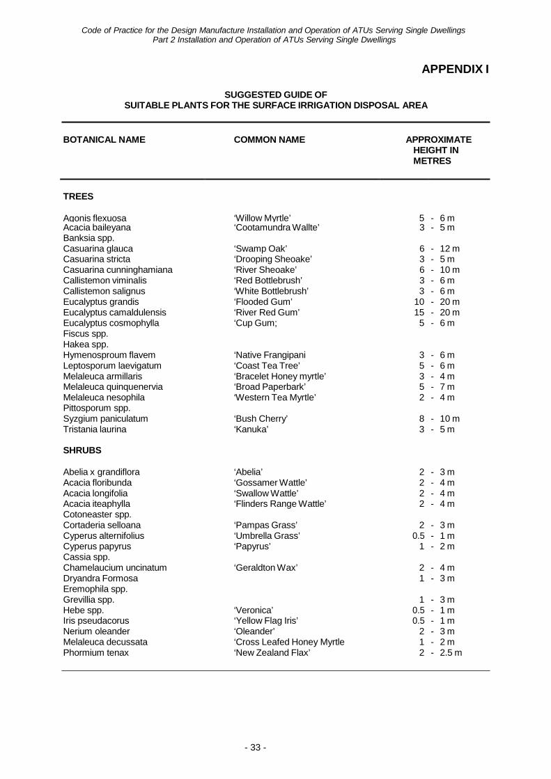
APPENDIX I
SUGGESTED GUIDE OF SUITABLE PLANTS FOR THE SURFACE IRRIGATION DISPOSAL AREA
BOTANICAL NAME COMMON NAME APPROXIMATE HEIGHT IN METRES
TREES
Agonis flexuosa
‘Willow Myrtle’
5
- 6 m
Acacia baileyana ‘Cootamundra Wallte’ 3 - 5 m Banksia spp. Casuarina glauca ‘Swamp Oak’ 6 - 12 m Casuarina stricta ‘Drooping Sheoake’ 3 - 5 m Casuarina cunninghamiana ‘River Sheoake’ 6 - 10 m Callistemon viminalis ‘Red Bottlebrush’ 3 - 6 m Callistemon salignus ‘White Bottlebrush’ 3 - 6 m Eucalyptus grandis ‘Flooded Gum’ 10 - 20 m Eucalyptus camaldulensis ‘River Red Gum’ 15 - 20 m Eucalyptus cosmophylla ‘Cup Gum; 5 - 6 m Fiscus spp. Hakea spp. Hymenosproum flavem ‘Native Frangipani 3 - 6 m Leptosporum laevigatum ‘Coast Tea Tree’ 5 - 6 m Melaleuca armillaris ‘Bracelet Honey myrtle’ 3 - 4 m Melaleuca quinquenervia ‘Broad Paperbark’ 5 - 7 m Melaleuca nesophila ‘Western Tea Myrtle’ 2 - 4 m Pittosporum spp. Syzgium paniculatum ‘Bush Cherry’ 8 - 10 m Tristania laurina ‘Kanuka’ 3 - 5 m
SHRUBS
Abelia x grandiflora ‘Abelia’ 2 - 3 m Acacia floribunda ‘Gossamer Wattle’ 2 - 4 m Acacia longifolia ‘Swallow Wattle’ 2 - 4 m Acacia iteaphylla ‘Flinders Range Wattle’ 2 - 4 m Cotoneaster spp. Cortaderia selloana ‘Pampas Grass’ 2 - 3 m Cyperus alternifolius ‘Umbrella Grass’ 0.5 - 1 m Cyperus papyrus ‘Papyrus’ 1 - 2 m Cassia spp. Chamelaucium uncinatum ‘Geraldton Wax’ 2 - 4 m Dryandra Formosa 1 - 3 m Eremophila spp. Grevillia spp. 1 - 3 m Hebe spp. ‘Veronica’ 0.5 - 1 m Iris pseudacorus ‘Yellow Flag Iris’ 0.5 - 1 m Nerium oleander ‘Oleander’ 2 - 3 m Melaleuca decussata ‘Cross Leafed Honey Myrtle 1 - 2 m Phormium tenax ‘New Zealand Flax’ 2 - 2.5 m
Code of Practice for the Design Manufacture Installation and Operation of ATUs Serving Single Dwellings
Part 2 Installation and Operation of ATUs Serving Single Dwellings
- 34 -
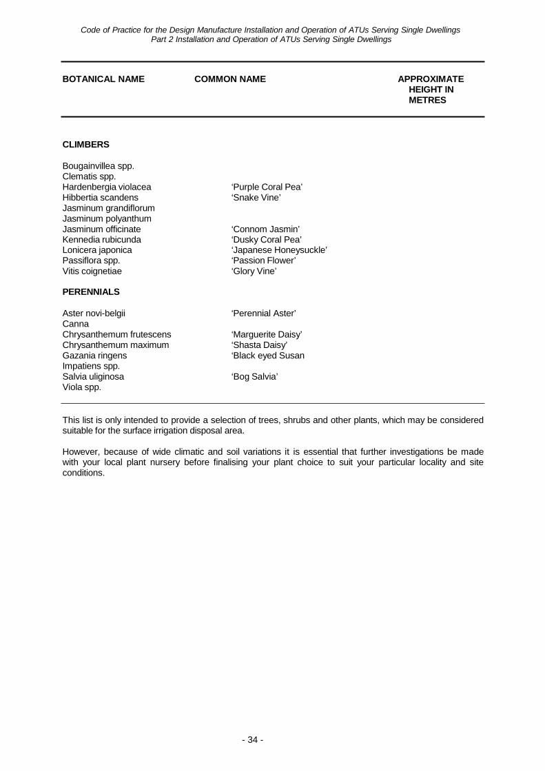
BOTANICAL NAME COMMON NAME APPROXIMATE
HEIGHT IN METRES
CLIMBERS
Bougainvillea spp. Clematis spp. Hardenbergia violacea ‘Purple Coral Pea’ Hibbertia scandens ‘Snake Vine’ Jasminum grandiflorum Jasminum polyanthum Jasminum officinate ‘Connom Jasmin’ Kennedia rubicunda ‘Dusky Coral Pea’ Lonicera japonica ‘Japanese Honeysuckle’ Passiflora spp. ‘Passion Flower’ Vitis coignetiae ‘Glory Vine’
PERENNIALS
Aster novi-belgii ‘Perennial Aster’ Canna Chrysanthemum frutescens ‘Marguerite Daisy’ Chrysanthemum maximum ‘Shasta Daisy’ Gazania ringens ‘Black eyed Susan Impatiens spp. Salvia uliginosa ‘Bog Salvia’ Viola spp.
This list is only intended to provide a selection of trees, shrubs and other plants, which may be considered suitable for the surface irrigation disposal area.
However, because of wide climatic and soil variations it is essential that further investigations be made with your local plant nursery before finalising your plant choice to suit your particular locality and site conditions.
Code of Practice for the Design Manufacture Installation and Operation of ATUs Serving Single Dwellings
Part 2 Installation and Operation of ATUs Serving Single Dwellings
- 35 -
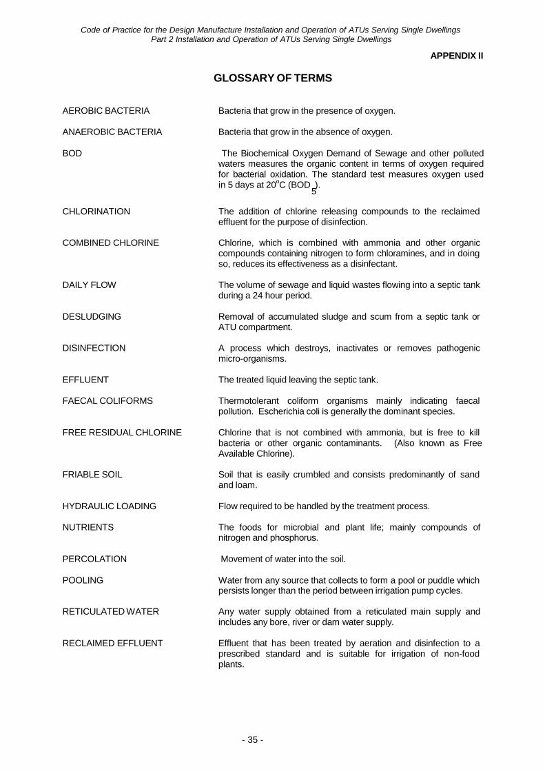
APPENDIX II
GLOSSARY OF TERMS AEROBIC BACTERIA Bacteria that grow in the presence of oxygen.
ANAEROBIC BACTERIA Bacteria that grow in the absence of oxygen.
BOD The Biochemical Oxygen Demand of Sewage and other polluted waters measures the organic content in terms of oxygen required for bacterial oxidation. The standard test measures oxygen used in 5 days at 20oC (BOD ).
5
CHLORINATION The addition of chlorine releasing compounds to the reclaimed effluent for the purpose of disinfection.
COMBINED CHLORINE Chlorine, which is combined with ammonia and other organic
compounds containing nitrogen to form chloramines, and in doing so, reduces its effectiveness as a disinfectant.
DAILY FLOW The volume of sewage and liquid wastes flowing into a septic tank
during a 24 hour period. DESLUDGING Removal of accumulated sludge and scum from a septic tank or
ATU compartment. DISINFECTION A process which destroys, inactivates or removes pathogenic
micro-organisms. EFFLUENT The treated liquid leaving the septic tank.
FAECAL COLIFORMS Thermotolerant coliform organisms mainly indicating faecal
pollution. Escherichia coli is generally the dominant species. FREE RESIDUAL CHLORINE Chlorine that is not combined with ammonia, but is free to kill
bacteria or other organic contaminants. (Also known as Free Available Chlorine).
FRIABLE SOIL Soil that is easily crumbled and consists predominantly of sand
and loam. HYDRAULIC LOADING Flow required to be handled by the treatment process.
NUTRIENTS The foods for microbial and plant life; mainly compounds of
nitrogen and phosphorus. PERCOLATION Movement of water into the soil.
POOLING Water from any source that collects to form a pool or puddle which
persists longer than the period between irrigation pump cycles. RETICULATED WATER Any water supply obtained from a reticulated main supply and
includes any bore, river or dam water supply. RECLAIMED EFFLUENT Effluent that has been treated by aeration and disinfection to a
prescribed standard and is suitable for irrigation of non-food plants.
Code of Practice for the Design Manufacture Installation and Operation of ATUs Serving Single Dwellings
Part 2 Installation and Operation of ATUs Serving Single Dwellings
- 36 -
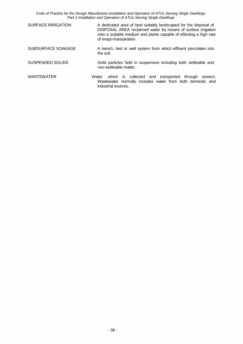
SURFACE IRRIGATION A dedicated area of land suitably landscaped for the disposal of DISPOSAL AREA reclaimed water by means of surface irrigation onto a suitable medium and plants capable of effecting a high rate of evapo-transpiration.
SUBSURFACE SOAKAGE A trench, bed or well system from which effluent percolates into
the soil. SUSPENDED SOLIDS Solid particles held in suspension including both settleable and
non-settleable matter. WASTEWATER Water which is collected and transported through sewers.
Wastewater normally includes water from both domestic and industrial sources.
Code of Practice for the Design Manufacture Installation and Operation of ATUs Serving Single Dwellings
Part 2 Installation and Operation of ATUs Serving Single Dwellings
- 37 -
APPENDIX III(a)
SITE LAYOUT PLAN TWO TANK SYSTEM – LAND FALL TO BACK OF BLOCK
ATU
- 38 -
Code of Practice for the Design Manufacture Installation and Operation of ATUs Serving Single Dwellings Part 2 Installation and Operation of ATUs Serving Single Dwellings
APPENDIX III(b)
SITE LAYOUT PLAN
TWO TANK SYSTEM, SPLIT DISPOSAL AREA – LAND FALL TO FRONT OF BLOCK
ATU
- 39 -
Code of Practice for the Design Manufacture Installation and Operation of ATUs Serving Single Dwellings Part 2 Installation and Operation of ATUs Serving Single Dwellings
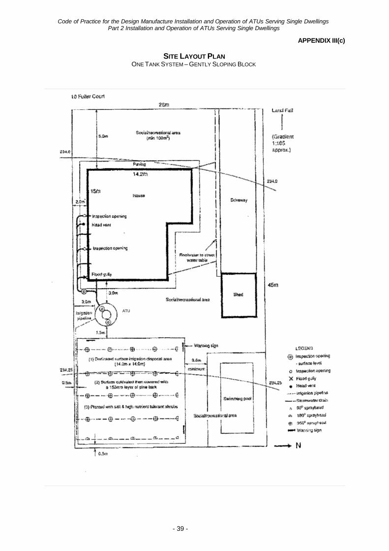
APPENDIX III(c)
SITE LAYOUT PLAN
ONE TANK SYSTEM – GENTLY SLOPING BLOCK
ATU
Code of Practice for the Design Manufacture Installation and Operation of ATUs Serving Single Dwellings
Part 2 Installation and Operation of ATUs Serving Single Dwellings
APPENDIX III(d)
TYPICAL SECTION THROUGH CUT/BENCHED SITE
- 40 -
- 41 -
Code of Practice for the Design Manufacture Installation and Operation of ATUs Serving Single Dwellings Part 2 Installation and Operation of ATUs Serving Single Dwellings
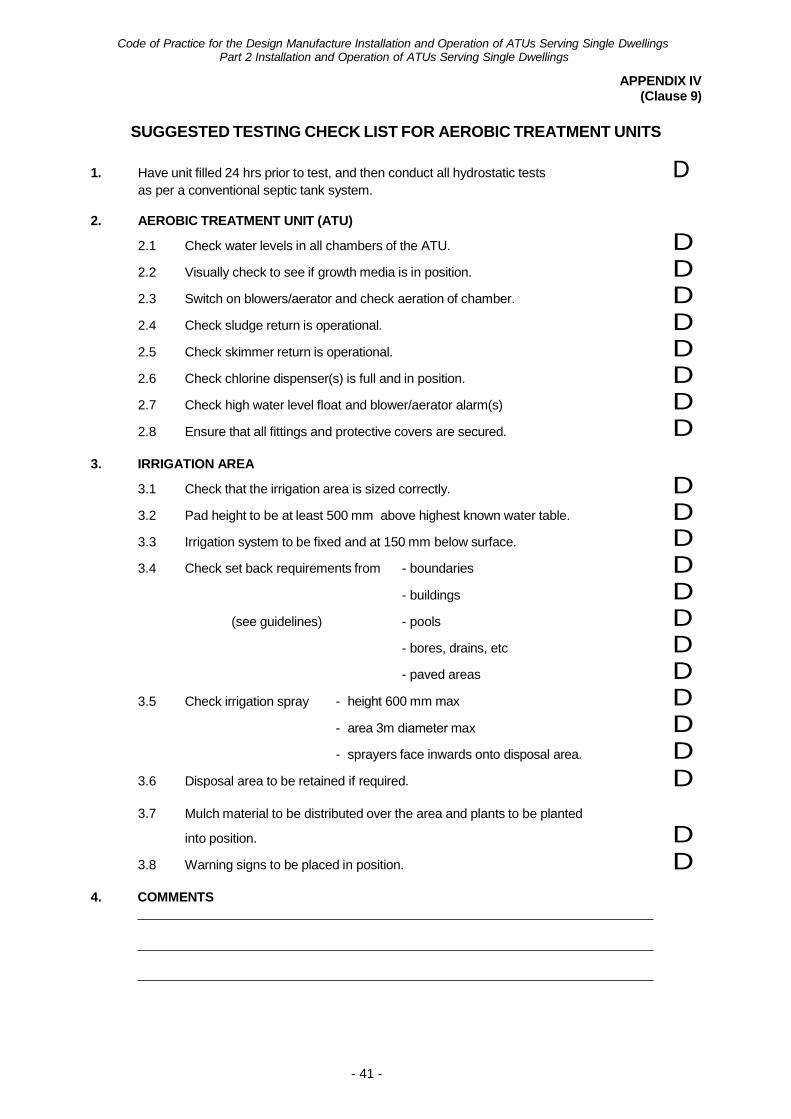
2.1 Check water levels in all chambers of the ATU. D2.2 Visually check to see if growth media is in position. D2.3 Switch on blowers/aerator and check aeration of chamber. D2.4 Check sludge return is operational. D2.5 Check skimmer return is operational. D2.6 Check chlorine dispenser(s) is full and in position. D2.7 Check high water level float and blower/aerator alarm(s) D2.8 Ensure that all fittings and protective covers are secured. DIRRIGATION AREA 3.1 Check that the irrigation area is sized correctly. D3.2 Pad height to be at least 500 mm above highest known water table. D3.3 Irrigation system to be fixed and at 150 mm below surface. D3.4 Check set back requirements from - boundaries D
3.5
(see guidelines)
Check irrigation spray
- buildings
- pools
- bores, drains, etc
- paved areas
DDDDD- height 600 mm max
- area 3m diameter max
- sprayers face inwards onto disposal area.
DD
3.6 Disposal area to be retained if required. D3.7 Mulch material to be distributed over the area and plants to be planted
into position. D3.8 Warning signs to be placed in position. D
APPENDIX IV (Clause 9)
SUGGESTED TESTING CHECK LIST FOR AEROBIC TREATMENT UNITS
1. Have unit filled 24 hrs prior to test, and then conduct all hydrostatic tests D as per a conventional septic tank system.
2. AEROBIC TREATMENT UNIT (ATU)
3.
4. COMMENTS
Code of Practice for the Design Manufacture Installation and Operation of ATUs Serving Single Dwellings
Part 2 Installation and Operation of ATUs Serving Single Dwellings
- 42 -
APPENDIX V
DRIPPER IRRIGATION DISPOSAL SYSTEM
1. SCOPE
Disposal of effluent from ATUs serving single dwellings is permitted by a dripper irrigation disposal system which complies with the criteria set out in this Appendix and subject to any conditions imposed in the approval of the dripper system.
The manufacturer shall not install a dripper irrigation disposal system which has not been approved by the CHO.
2. TYPE OF SYSTEM
A dripper irrigation disposal system shall be one of the following:
2.1 Sub-strata dripper system where the system is placed on top of the ground
surface and covered with a minimum of 100mm of approved material (e.g. bark, woodchip) placed over the irrigation pipework.
Attachment No 1 details the installation requirements for various soil types.
2.2 Sub-surface dripper system where the system is buried a minimum of 150mm
below the ground surface.
Attachment No. 2 details the installation requirements for various soil types.
3. SETBACK REQUIREMENTS
The minimum setback requirements from dripper irrigation areas shall comply with distances as shown in Table 1. However, a local government may, except for the setback distances relating to groundwater bores, require a greater distance where site conditions or circumstance warrant an increased setback.
Code of Practice for the Design Manufacture Installation and Operation of ATUs Serving Single Dwellings Part 2 Installation and Operation of ATUs Serving Single Dwellings
- 43 -
TABLE NO. 1 – MINIMUM SETBACK DISTANCES
Note: Distance measured from pipework
Item Sub-strata Drippers (m) Sub-surface Drippers (m) Opened Fenced Boundaries 0.5 0.5 Closed Fencing 0.5 0.5 Buildings 0.5 0.5 Sub-soil/Open Drains 3.0 3.0 Swimming Pools 2.0 0.5 Bores* - potable 30.0 30.0
- garden 10.0 10.0 ATUs 0.5 0.5 Paths, drives, carports etc. 0.5 0.5
*Only CHO may vary this setback requirement.
4. DISPOSAL AREA
4.1 The disposal area requirements for sub-strata or sub-surface dripper irrigation systems shall comply with the following:
Sandy Soils
1 – 2 bedrooms 60m2
3 bedrooms 80m2
4 bedrooms 90m2
5 bedrooms 100m2
All other Soils*
Up to 5 bedrooms 150m2
* Where site conditions are such that effective disposal cannot be achievedwithin the 150m2 requirement, the local government may stipulate anincreased disposal area.
4.2 The disposal area shall be maintained as a permanent dedicated area for the purposes of effluent disposal. In addition the area set aside for a sub-strata system be a passive area (i.e. not subject to human traffic).
4.3 No part of the disposal area shall be altered by any person without the prior approval of the local government.
4.4 The sub-strata dripper irrigation areas shall be planted out prior to use with suitable plants or shrubs.
4.5 No part of a sub-strata or sub-surface dripper irrigation system shall be paved or built over. The disposal area must be maintained in such a manner to provide access for maintenance.
4.6 At least two warning signs shall be posted within the irrigation areas as required under Clause 4(a) of this Part.
4.7 All storm or surface water must be diverted away from the disposal area, and stormwater disposal systems must be excluded from the area.
4.8 Where seepage into the disposal area is likely to occur, cut-off drains shall be installed.
Code of Practice for the Design Manufacture Installation and Operation of ATUs Serving Single Dwellings
Part 2 Installation and Operation of ATUs Serving Single Dwellings
- 44 -
4.9 The growing of vegetables on any part of a disposal area is not permitted.
4.10 Cover material over a sub-strata irrigation area shall be maintained at the required thickness (100mm) at all times.
4.11 The requirement to provide 100m2 for social recreation purposes is only
required where a sub-strata dripper irrigation system is installed.
5. IRRIGATION MATERIALS
All pipework and fittings shall be polyethylene complying with AS 2698, ‘Plastics pipes and fittings for irrigation and rural applications’.
6. SLOPE
Where the proposed site for the irrigation area has a slope greater than 1 in 20, the area shall be terraced and designed to prevent run-off from the disposal area.
The top surface area for any disposal area must be prepared and maintained as a level surface to prevent erosion or run-off from the disposal area.
7. GROUNDWATER CLEARANCE
A minimum clearance of 0.5m of unsaturated soil between the dripper lines and highest known water table or impermeable layer shall be maintained at all times, except for reduced irrigation areas, where the groundwater clearance shall comply with Clause 4(b)(ii) of this Part.
8. CHLORINATION
Effluent disposed by dripper irrigation systems shall be chlorinated to prevent organic growth in the distribution pipework and fittings.
9. PHOSPHORUS REMOVAL
A dripper irrigation system is not approved for use with amended soil to meet the requirements of Section 5.1 of the Government Sewerage Policy, Perth Metropolitan Region, or in environmentally sensitive areas.
10. SUBMISSION OF PLANS
The block plan required with the application of an apparatus under the Regulations, shall be in duplicate and drawn to a scale of 1 in 100 and include additional details as follows:
• block dimensions. • contours indicating natural ground level, wells, bores, dams, creeks, watercourses
and sub-soil drainage systems. • proposed location of all buildings and other structures and paved areas. • setback distances from boundaries, buildings, paved areas etc. • location of irrigation effluent disposal area and type of system used (sub-strata/sub-
surface). • position of irrigation effluent lines, drippers, filters, relief valves etc. • where slope greater than 1 in 20 terracing details. • position and depth of cut-ff drains. • A schedule of each component (e.g. pump detail, type and number of emitters,
relief valves etc) used for the specific system to be installed on that site.
11. INSTALLATION AND CERTIFICATION
- 45 -
Code of Practice for the Design Manufacture Installation and Operation of ATUs Serving Single Dwellings Part 2 Installation and Operation of ATUs Serving Single Dwellings
A dripper irrigation system shall only be installed by the manufacturer and who shall provide written certification to the local government prior to the local government issuing a certificate to use the apparatus, stating the system complies with and is installed in accordance with the approval granted to the manufacturer under Schedule No. 1 of this Appendix – Technical Information.
12. SCHEDULE OF GUARANTEED TECHNICAL INFORMATION
The manufacturer shall complete and sign Schedule No. 1 of this Appendix and submit it to the CHO for approval of any dripper irrigation effluent disposal system.
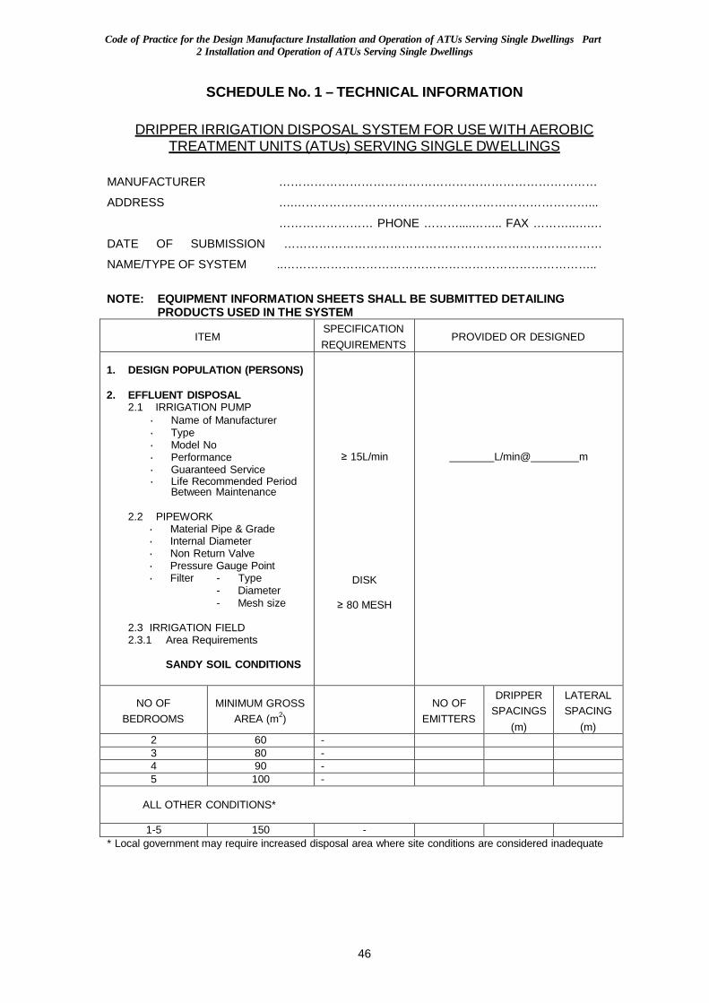
Code of Practice for the Design Manufacture Installation and Operation of ATUs Serving Single Dwellings Part
2 Installation and Operation of ATUs Serving Single Dwellings
46
SCHEDULE No. 1 – TECHNICAL INFORMATION
DRIPPER IRRIGATION DISPOSAL SYSTEM FOR USE WITH AEROBIC
TREATMENT UNITS (ATUs) SERVING SINGLE DW ELLINGS
MANUFACTURER ………………………………………………………………………
ADDRESS ….…………………………………………………………………...
…………………… PHONE ………....…….. FAX ………..….…
DATE OF SUBMISSION ………………………………………………………………………
NAME/TYPE OF SYSTEM ..……………………………………………………………………..
NOTE: EQUIPMENT INFORMATION SHEETS SHALL BE SUBMITTED DETAILING
PRODUCTS USED IN THE SYSTEM
ITEM SPECIFICATION REQUIREMENTS
PROVIDED OR DESIGNED
1. DESIGN POPULATION (PERSONS)
2. EFFLUENT DISPOSAL
2.1 IRRIGATION PUMP • Name of Manufacturer • Type • Model No • Performance • Guaranteed Service • Life Recommended Period
Between Maintenance
2.2 PIPEWORK • Material Pipe & Grade • Internal Diameter • Non Return Valve • Pressure Gauge Point • Filter - Type
- Diameter - Mesh size
2.3 IRRIGATION FIELD 2.3.1 Area Requirements
SANDY SOIL CONDITIONS
≥ 15L/min
DISK
≥ 80 MESH
L/min@ m
NO OF
BEDROOMS MINIMUM GROSS
AREA (m2)
NO OF
EMITTERS
DRIPPER SPACINGS
(m)
LATERAL SPACING
(m) 2 60 - 3 80 - 4 90 - 5 100 -
ALL OTHER CONDITIONS*
1-5 150 - * Local government may require increased disposal area where site conditions are considered inadequate
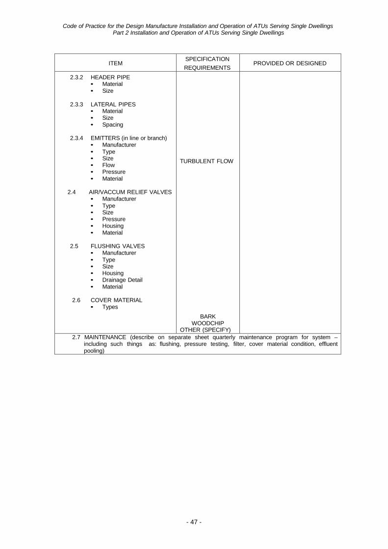
Code of Practice for the Design Manufacture Installation and Operation of ATUs Serving Single Dwellings
Part 2 Installation and Operation of ATUs Serving Single Dwellings
- 47 -
ITEM SPECIFICATION
REQUIREMENTS
PROVIDED OR DESIGNED
2.3.2 HEADER PIPE • Material • Size
2.3.3 LATERAL PIPES
• Material • Size • Spacing
2.3.4 EMITTERS (in line or branch)
• Manufacturer • Type • Size • Flow • Pressure • Material
2.4 AIR/VACCUM RELIEF VALVES
• Manufacturer • Type • Size • Pressure • Housing • Material
2.5 FLUSHING VALVES
• Manufacturer • Type • Size • Housing • Drainage Detail • Material
2.6 COVER MATERIAL
• Types
TURBULENT FLOW
BARK WOODCHIP
OTHER (SPECIFY)
2.7 MAINTENANCE (describe on separate sheet quarterly maintenance program for system – including such things as: flushing, pressure testing, filter, cover material condition, effluent pooling)
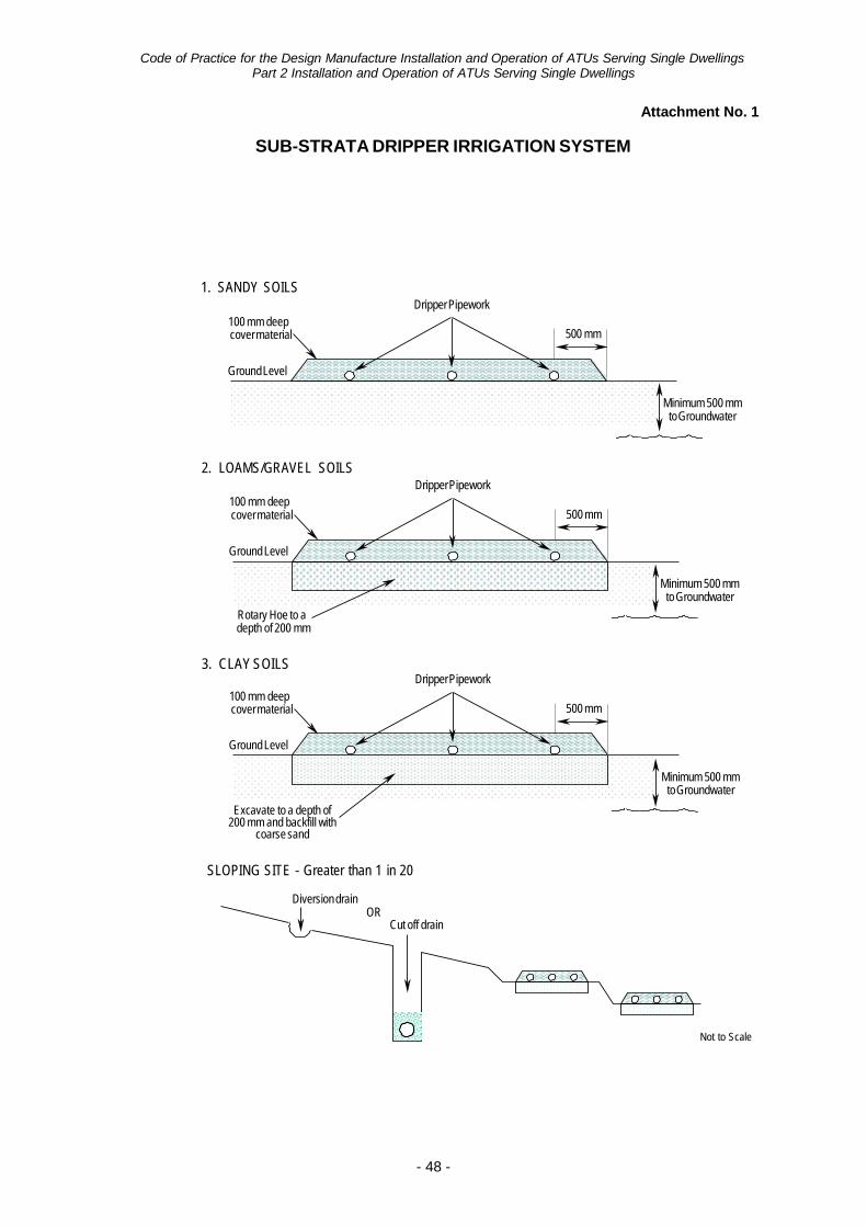
- 48 -
Code of Practice for the Design Manufacture Installation and Operation of ATUs Serving Single Dwellings Part 2 Installation and Operation of ATUs Serving Single Dwellings
Attachment No. 1
SUB-STRATA DRIPPER IRRIGATION SYSTEM
1. SANDY SOILS
100 mm deep cover material
Dripper Pipework
500 mm
Ground Level
Minimum 500 mm to Groundwater
2. LOAMS/GRAVEL SOILS
100 mm deep cover material
Dripper Pipework
500 mm
Ground Level
Rotary Hoe to a depth of 200 mm
Minimum 500 mm to Groundwater
3. CLAY SOILS
100 mm deep cover material
Dripper Pipework
500 mm
Ground Level
Excavate to a depth of 200 mm and backfill with
coarse sand
Minimum 500 mm to Groundwater
SLOPING SITE - Greater than 1 in 20
Diversion drain
OR Cut off drain
Not to Scale
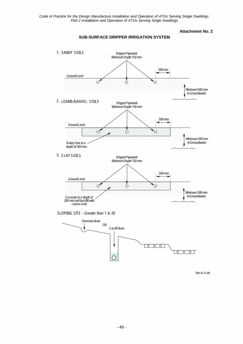
- 49 -
Code of Practice for the Design Manufacture Installation and Operation of ATUs Serving Single Dwellings Part 2 Installation and Operation of ATUs Serving Single Dwellings
Attachment No. 2
SUB-SURFACE DRIPPER IRRIGATION SYSTEM
1. SANDY SOILS Dripper Pipework Minimum Depth 150 mm
Ground Level
500 mm
2. LOAMS/GRAVEL SOILS
Ground Level
Dripper Pipework Minimum Depth 150 mm
500 mm
Minimum 500 mm to Groundwater
Rotary Hoe to a depth of 200 mm
3. CLAY SOILS
Ground Level
Dripper Pipework Minimum Depth 150 mm
500 mm
Minimum 500 mm to Groundwater
Excavate to a depth of 200 mm and backfill with
coarse sand
Minimum 500 mm to Groundwater
SLOPING SITE - Greater than 1 in 20
Diversion drain
OR Cut off drain
Not to Scale
This document can be made available in alternative formats on request for a person with a disability
© Department of Health 2015 Copyright to this material is vested in the State of Western Australia unless otherwise indicated. Apart from any fair dealing for the purposes of private study, research, criticism or review, as permitted under the provisions of the Copyright Act 1968, no part may be reproduced or re-used for any purposes whatsoever without written permission of the State of Western Australia.