rotor dynamics
TRANSCRIPT
Dr. R. Tiwari ([email protected])
ByDr. Rajiv Tiwari
Department of Mechanical EngineeringIndian Institute of Technology Guwahati 781039
Under AICTE Sponsored QIP Short Term Course on
Theory & Practice of Rotor Dynamics(15-19 Dec 2008)
IIT Guwahati
A Brief History and State of the Art of Rotor Dynamics
Dr. R. Tiwari ([email protected])
Outline of the Presentation
• Introduction and Definition
• History from Rakine (1869) to Jeffcott (1919)
from Stodola (1924) to Lund (1964)
from Dimentberg (1965) to till now
• Development of Rotor Dynamics Analysis Tools
• Softwares for Rotor Dynamics Analysis
Dr. R. Tiwari ([email protected])
• Dynamic Balancing of Rotors
• Condition Monitoring of Rotating Machineries
• Conclusions & Recent Trends
Outline of the Presentation
Dr. R. Tiwari ([email protected])
• A brief history of rotor dynamics field has been documented in the present review paper.
• It reviews early development of simple rotor models, analyses tools, and physical interpretations of various kind of instabilities in rotor-bearing systems.
• It also reviews developments of analysis methods for the continuous and multi-degrees-of freedom systems that allowed practicing engineers to apply these methods to real turbo-machineries.
• The paper also summaries work on dynamic balancing of rotors, vibration based conditioning monitoring, and recent trends in the area of rotor dynamics.
Introduction
Dr. R. Tiwari ([email protected])
• A rotor is a body suspended through a set of cylindrical hinges or bearings that allow it to rotate freely about an axis fixed in space.
• Engineering components concerned with the subject of rotor dynamics are rotors in machines, especially of turbines, generators, motors, compressors, blowers and the like.
• The parts of the machine that do not rotate are referred to with general definition of stator.
• Rotors of machines have, while in operation, a great deal of rotational energy, and a small amount of vibrational energy.
Introduction
Dr. R. Tiwari ([email protected])
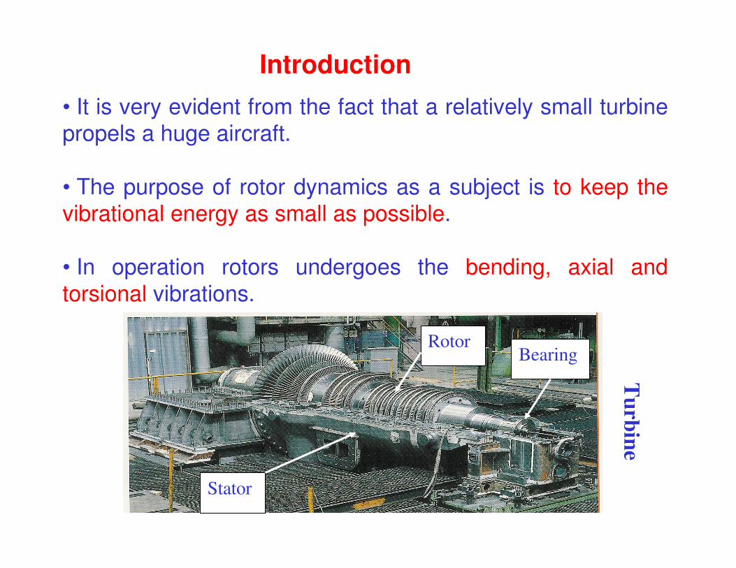
• It is very evident from the fact that a relatively small turbine propels a huge aircraft.
• The purpose of rotor dynamics as a subject is to keep the vibrational energy as small as possible.
• In operation rotors undergoes the bending, axial and torsional vibrations.
Introduction
Rotor
Stator
Bearing
Turbine
Dr. R. Tiwari ([email protected])
History of rotor dynamics from Rakine (1869) to Jeffcott (1919)
• Rotor dynamics has a remarkable history of developments, largely due to the interplay between its theory and its practice.
• Rotor dynamics has been driven more by its practice than by its theory. This statement is particularly relevant to the early history of rotor dynamics.
• Research on rotor dynamics spans at least 14 decades of history.
Dr. R. Tiwari ([email protected])
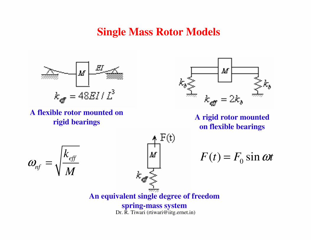
Single Mass Rotor Models
A flexible rotor mounted on rigid bearings A rigid rotor mounted
on flexible bearings
An equivalent single degree of freedom spring-mass system
effnf
k
Mω = 0( ) sinF t F tω=
Dr. R. Tiwari ([email protected])
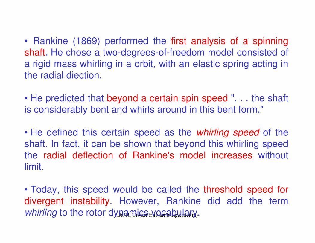
• Rankine (1869) performed the first analysis of a spinning shaft. He chose a two-degrees-of-freedom model consisted of a rigid mass whirling in a orbit, with an elastic spring acting in the radial diection.
• He predicted that beyond a certain spin speed ". . . the shaft is considerably bent and whirls around in this bent form."
• He defined this certain speed as the whirling speed of the shaft. In fact, it can be shown that beyond this whirling speed the radial deflection of Rankine's model increases without limit.
• Today, this speed would be called the threshold speed for divergent instability. However, Rankine did add the term whirling to the rotor dynamics vocabulary.
Dr. R. Tiwari ([email protected])
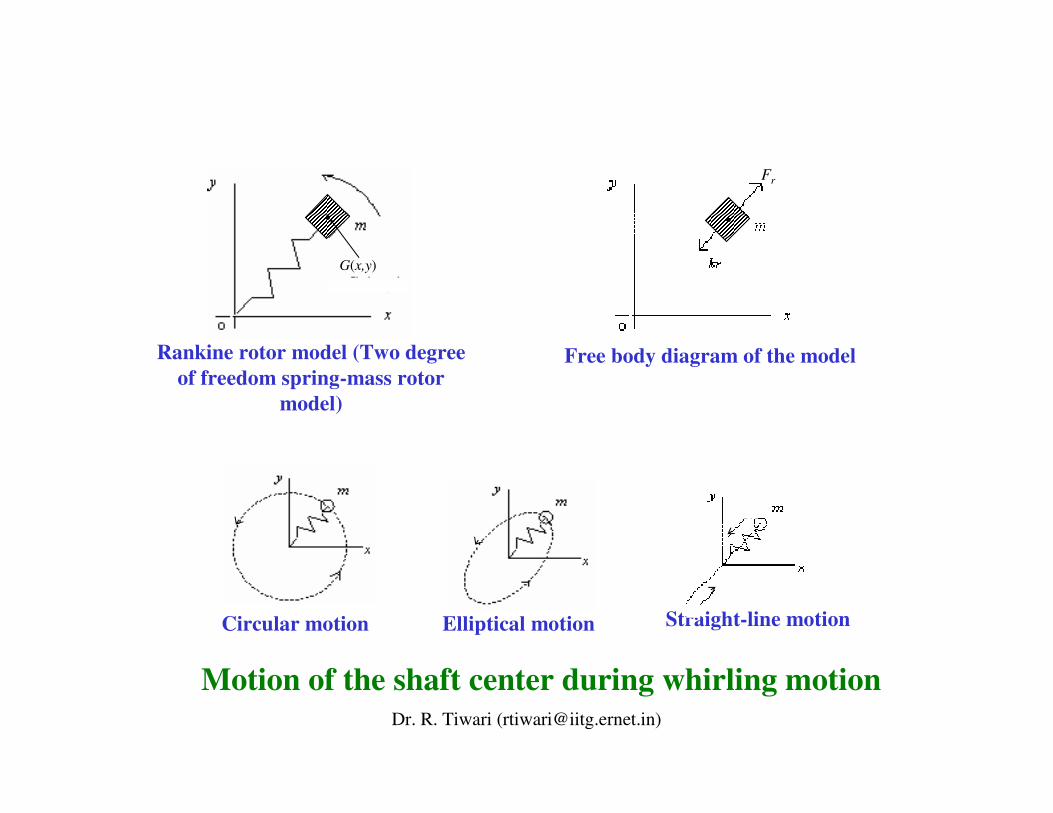
Free body diagram of the model
Fr
Rankine rotor model (Two degree of freedom spring-mass rotor
model)
G(x,y)
Circular motion Elliptical motion Straight-line motion
Motion of the shaft center during whirling motion
Dr. R. Tiwari ([email protected])
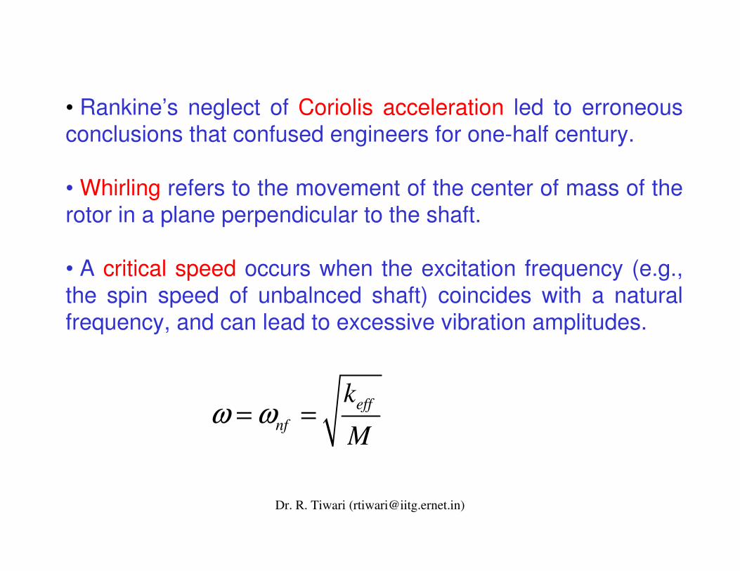
• Rankine’s neglect of Coriolis acceleration led to erroneous conclusions that confused engineers for one-half century.
• Whirling refers to the movement of the center of mass of the rotor in a plane perpendicular to the shaft.
• A critical speed occurs when the excitation frequency (e.g., the spin speed of unbalnced shaft) coincides with a natural frequency, and can lead to excessive vibration amplitudes.
effnf
k
Mω ω= =
Dr. R. Tiwari ([email protected])
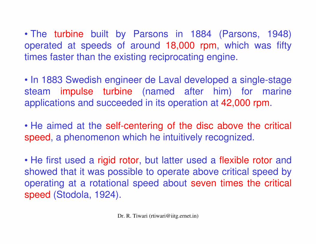
• The turbine built by Parsons in 1884 (Parsons, 1948) operated at speeds of around 18,000 rpm, which was fifty times faster than the existing reciprocating engine.
• In 1883 Swedish engineer de Laval developed a single-stage steam impulse turbine (named after him) for marine applications and succeeded in its operation at 42,000 rpm.
• He aimed at the self-centering of the disc above the critical speed, a phenomenon which he intuitively recognized.
• He first used a rigid rotor, but latter used a flexible rotor and showed that it was possible to operate above critical speed by operating at a rotational speed about seven times the critical speed (Stodola, 1924).
Dr. R. Tiwari ([email protected])
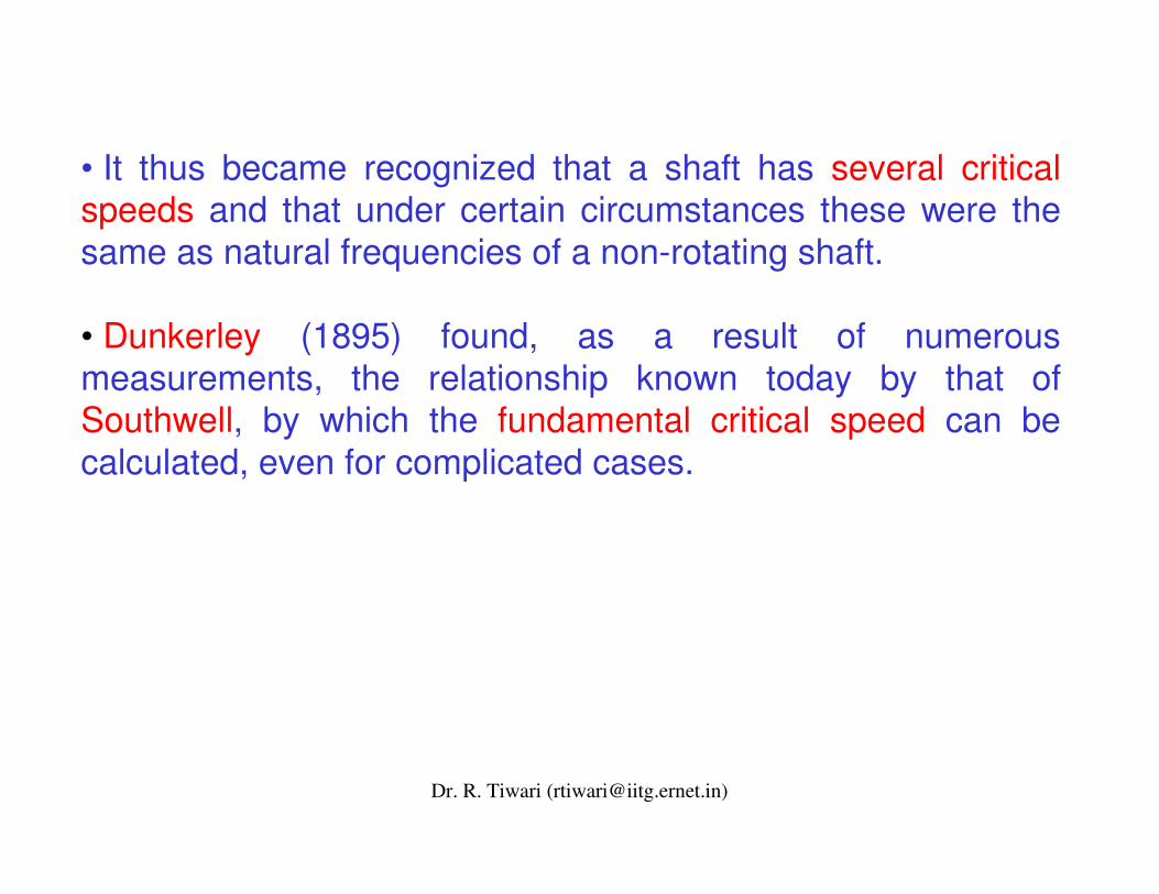
• It thus became recognized that a shaft has several critical speeds and that under certain circumstances these were the same as natural frequencies of a non-rotating shaft.
• Dunkerley (1895) found, as a result of numerous measurements, the relationship known today by that of Southwell, by which the fundamental critical speed can be calculated, even for complicated cases.
Dr. R. Tiwari ([email protected])
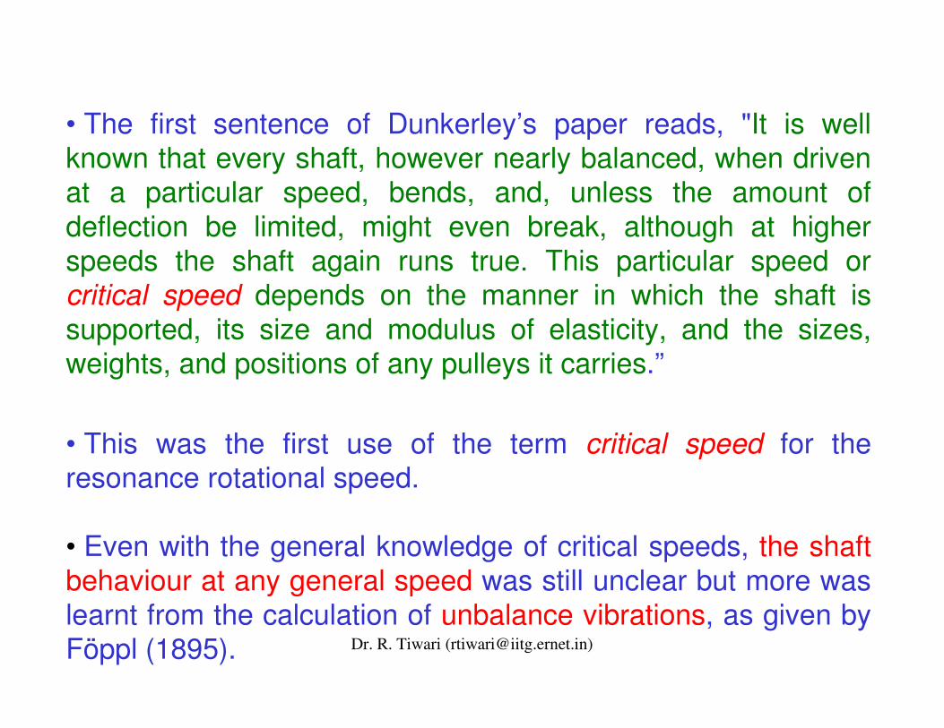
• The first sentence of Dunkerley’s paper reads, "It is well known that every shaft, however nearly balanced, when driven at a particular speed, bends, and, unless the amount of deflection be limited, might even break, although at higher speeds the shaft again runs true. This particular speed or critical speed depends on the manner in which the shaft is supported, its size and modulus of elasticity, and the sizes, weights, and positions of any pulleys it carries.”
• This was the first use of the term critical speed for the resonance rotational speed.
• Even with the general knowledge of critical speeds, the shaft behaviour at any general speed was still unclear but more was learnt from the calculation of unbalance vibrations, as given by Föppl (1895).
Dr. R. Tiwari ([email protected])
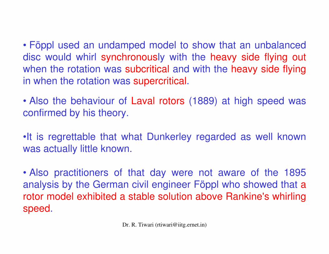
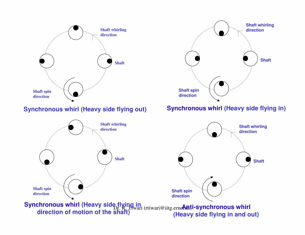
• Föppl used an undamped model to show that an unbalanced disc would whirl synchronously with the heavy side flying outwhen the rotation was subcritical and with the heavy side flying in when the rotation was supercritical.
• Also the behaviour of Laval rotors (1889) at high speed was confirmed by his theory.
•It is regrettable that what Dunkerley regarded as well known was actually little known.
• Also practitioners of that day were not aware of the 1895 analysis by the German civil engineer Föppl who showed that a rotor model exhibited a stable solution above Rankine's whirlingspeed.
Dr. R. Tiwari ([email protected])
Shaft spin direction
Shaft whirling direction
Shaft
Shaft spin direction
Shaft whirling direction
Shaft
Synchronous whirl (Heavy side flying out)
Anti-synchronous whirl (Heavy side flying in and out)
Shaft spin direction
Shaft whirling direction
Shaft
Synchronous whirl (Heavy side flying in)
Shaft spin direction
Shaft whirling direction
Shaft
Synchronous whirl (Heavy side flying in direction of motion of the shaft)
Dr. R. Tiwari ([email protected])Synchronous whirl (Heavy side flying out)
Dr. R. Tiwari ([email protected])Synchronous whirl (Heavy side flying in)

Dr. R. Tiwari ([email protected])Anti-synchronous (backward) whirl (Heavy side flying in and out)
Dr. R. Tiwari ([email protected])
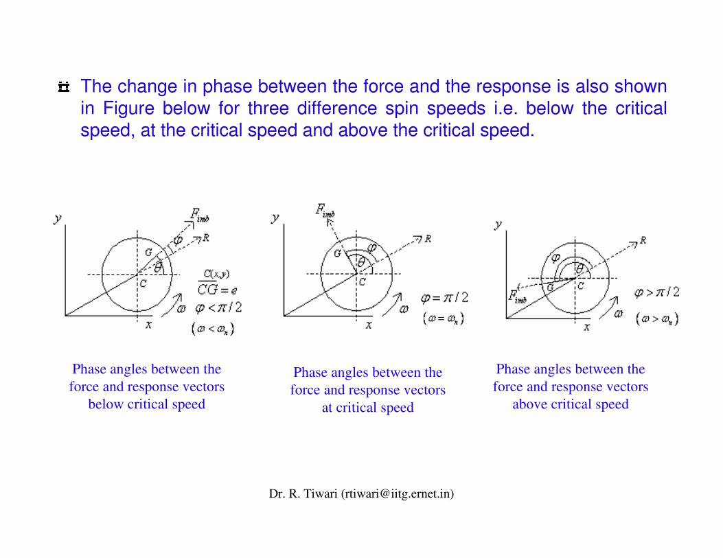
The change in phase between the force and the response is also shown in Figure below for three difference spin speeds i.e. below the critical speed, at the critical speed and above the critical speed.
Phase angles between the force and response vectors
below critical speed
Phase angles between the force and response vectors
at critical speed
Phase angles between the force and response vectors
above critical speed
Dr. R. Tiwari ([email protected])
• We cannot blame them too much since Föppl published his analysis in Der Civilingenieur, a journal that was probably not well known by contemporary rotor dynamicists.
• More telling was about the apparent indifference to the practical work of the Swedish engineer, De Laval, who in 1889 ran a single stage steam turbine at a supercritical speed.
Dr. R. Tiwari ([email protected])
• One can speculate that engineers of the day laboured under a confusion of concepts - equating Rankine's whirling speed (for present day it is the threshold speed for divergent instability) with Dunkerley's critical speed.
• This was particularly unfortunate since Rankine was far more eminent than Dunkerley and, as a result, his dire predictions were widely accepted and became responsible for discouraging the development of high speed rotors for almost 50 years (1869-1916).
• It was in England in 1916 that things came to the end. Kerrpublished experimental evidence that a second critical speedexisted, and it was obvious to all that a second critical speed could only be attained by the safe traversal of the first critical speed.
Dr. R. Tiwari ([email protected])
• The Royal Society of London then commissioned Jeffcott to resolve this conflict between Rankine's theory and the practice of Kerr and de Laval.
• The first recorded fundamental theory of rotor dynamics can be found in a classic paper of Jeffcott in 1919, in a place where it was more likely to be read by those interested in rotor dynamics.
• Jeffcott confirmed Föppl's prediction that a stable supercritical solution existed and he extended Foppl's analysis by including external damping (i.e., damping to ground) and showed that the phase of the heavy spot varies continuously as the rotation rate passes through the critical speed.
• There is no evidence that Jeffcott was aware of Föppl's prior work; in fact, Jeffcott's paper does not contain a single reference.
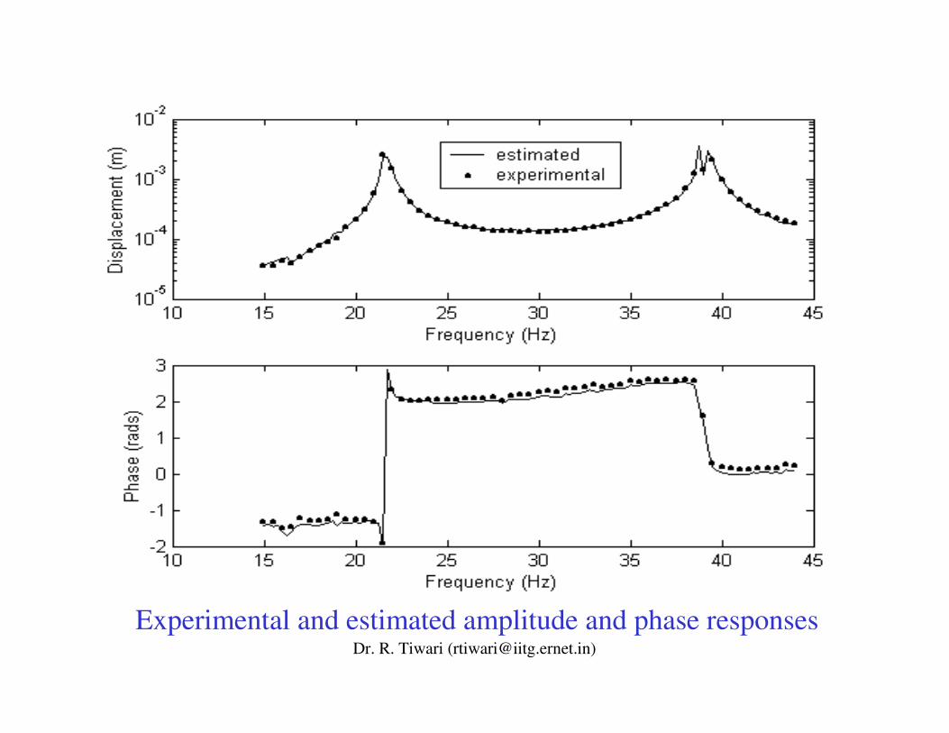
Dr. R. Tiwari ([email protected])Experimental and estimated amplitude and phase responses
Dr. R. Tiwari ([email protected])
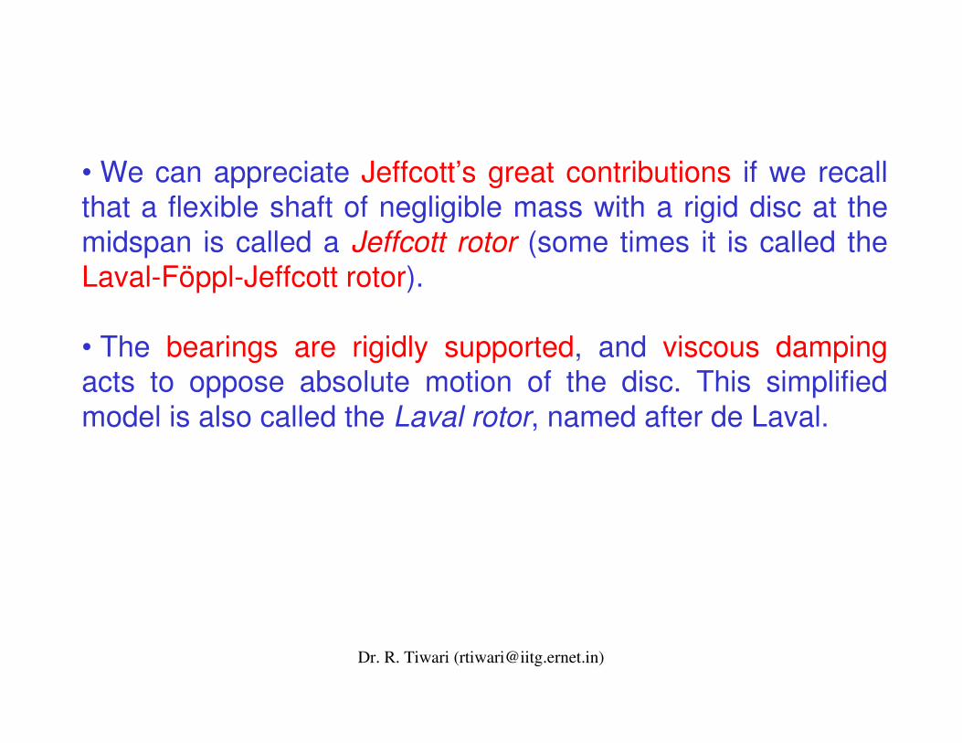
• We can appreciate Jeffcott’s great contributions if we recall that a flexible shaft of negligible mass with a rigid disc at the midspan is called a Jeffcott rotor (some times it is called the Laval-Föppl-Jeffcott rotor).
• The bearings are rigidly supported, and viscous dampingacts to oppose absolute motion of the disc. This simplified model is also called the Laval rotor, named after de Laval.
Dr. R. Tiwari ([email protected])
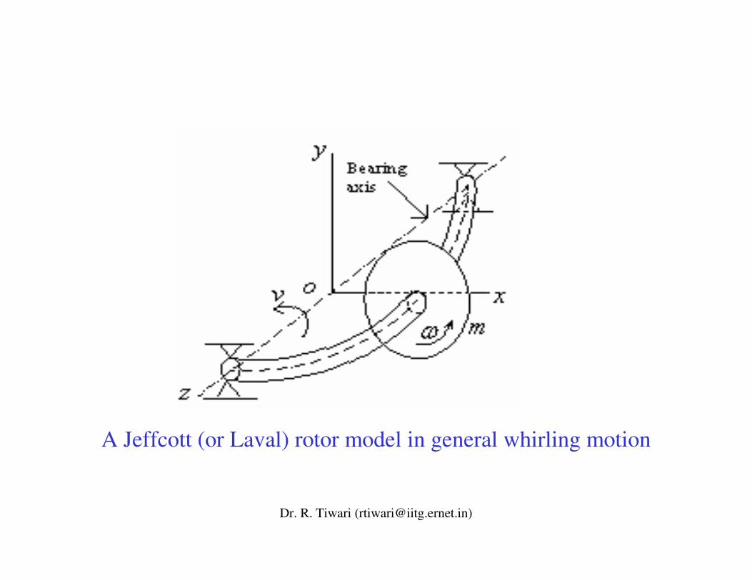
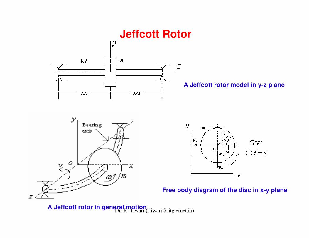
Jeffcott Rotor
Free body diagram of the disc in x-y plane
A Jeffcott rotor model in y-z plane
A Jeffcott rotor in general motion
Dr. R. Tiwari ([email protected])
Stodola (1924) to Lund (1964)• Developments made in rotor dynamics up to the beginning of the twentieth century are detailed in the masterpiece book written by Stodola (1924).
• Among other things, this book includes the dynamics of elastic shaft with discs, the dynamics of continuous rotors without considering gyroscopic moment, the secondary resonance phenomenon due to gravity effect, the balancing of rotors, and methods of determining approximate values of critical speeds of rotors with variable cross sections.
• He presented a graphical procedure to calculate critical speeds, which was widely used. He showed that these supercritical solutions were stabilized by Coriolis accelerations(which eventually gives gyroscopic effects).
Dr. R. Tiwari ([email protected])
• The unwitting constraint of these accelerations was the defect in Rankine's model. It is interesting to note that Rankine's model is a sensible one for a rotor whose stiffness in one direction is much greater than its stiffness in the quadrature direction.
• Indeed, it is now well known that such a rotor will have regions of divergent instability.
• It is less well known that Prandtl (1918) was the first to study a Jeffcott rotor with a non-circular cross-section (i.e., elastic asymmetry in the rotor).
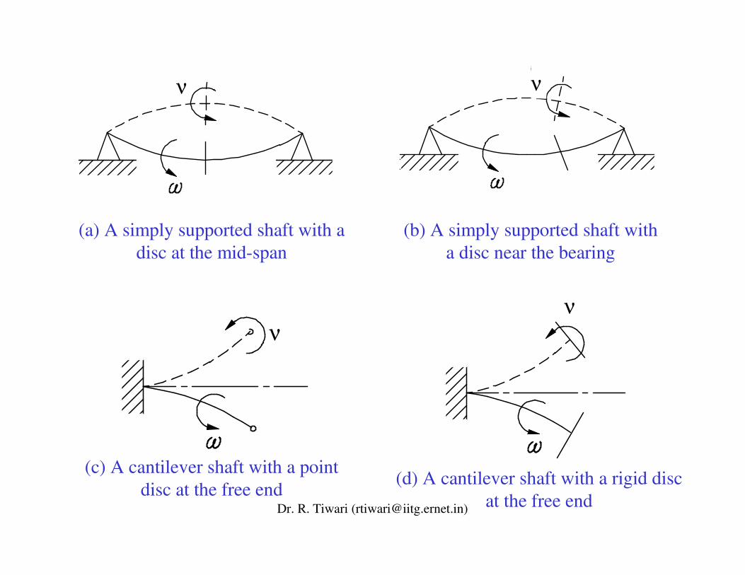
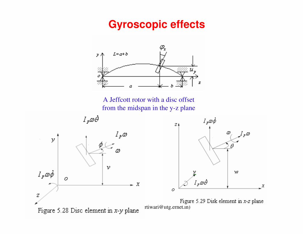
• In Jeffcott's analytical model the disk did not wobble. As a result, the angular velocity vector and the angular momentum vector were colinear and no gyroscopic moments were generated.
Dr. R. Tiwari ([email protected])
ν
ν
(b) A simply supported shaft with a disc near the bearing
(d) A cantilever shaft with a rigid disc at the free end
ν
ν
(a) A simply supported shaft with a disc at the mid-span
(c) A cantilever shaft with a point disc at the free end
Dr. R. Tiwari ([email protected])
Gyroscopic effects
A Jeffcott rotor with a disc offset from the midspan in the y-z plane
Dr. R. Tiwari ([email protected])
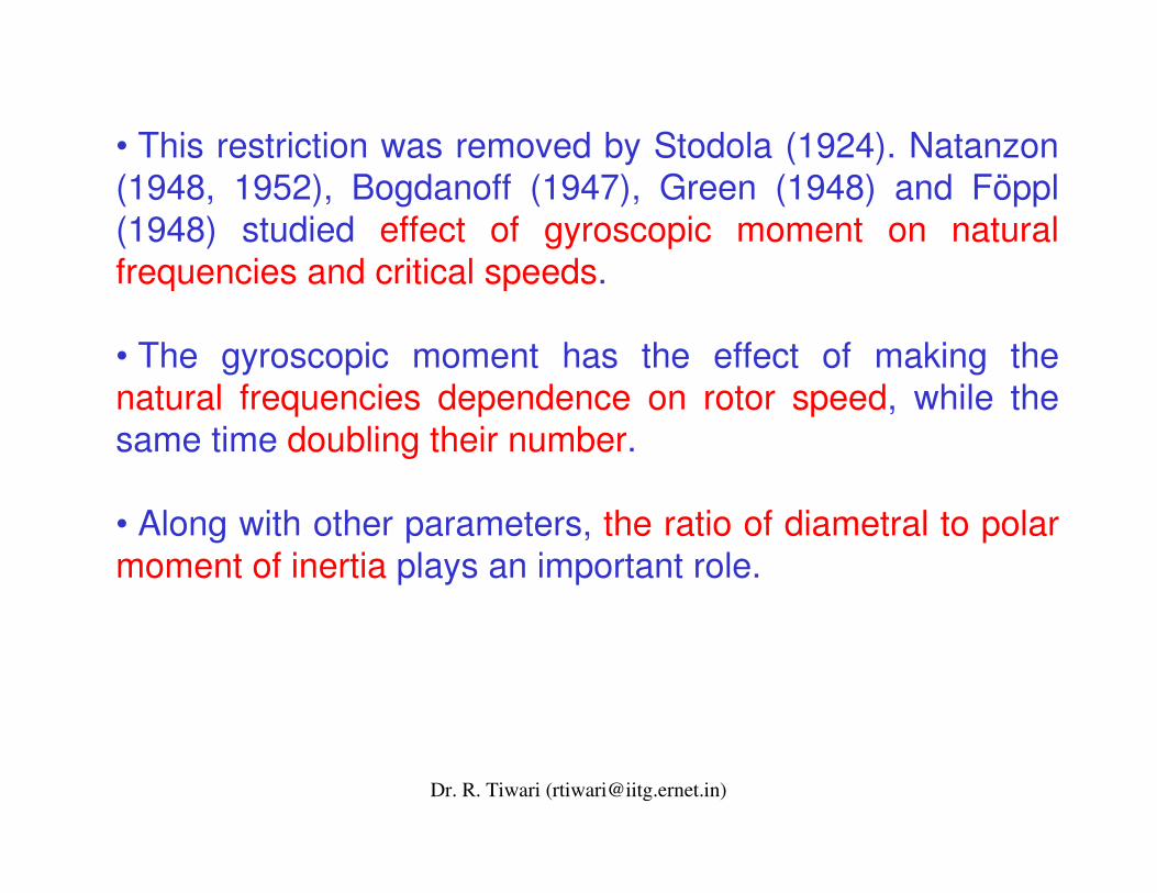
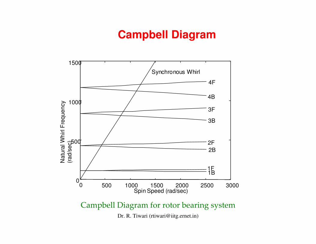
• This restriction was removed by Stodola (1924). Natanzon(1948, 1952), Bogdanoff (1947), Green (1948) and Föppl (1948) studied effect of gyroscopic moment on natural frequencies and critical speeds.
• The gyroscopic moment has the effect of making the natural frequencies dependence on rotor speed, while the same time doubling their number.
• Along with other parameters, the ratio of diametral to polar moment of inertia plays an important role.
Dr. R. Tiwari ([email protected])
Campbell Diagram
0 500 1000 1500 2000 2500 3000 0
500
1000
1500
Spin Speed (rad/sec)
Nat
ural
Whi
rl F
requ
ency
(r
ad/s
ec)
Synchronous Whirl
2F 2B
3B
4B
1B 1F
3F
4F
��������������� �����������������������
Dr. R. Tiwari ([email protected])
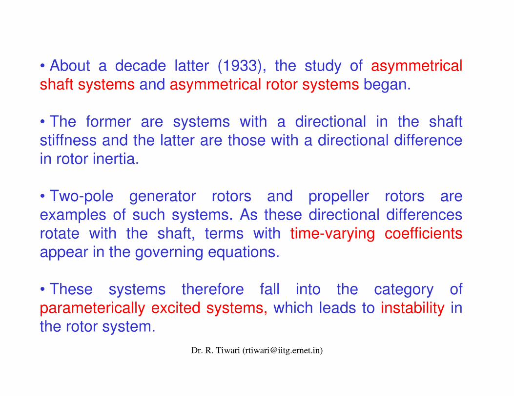
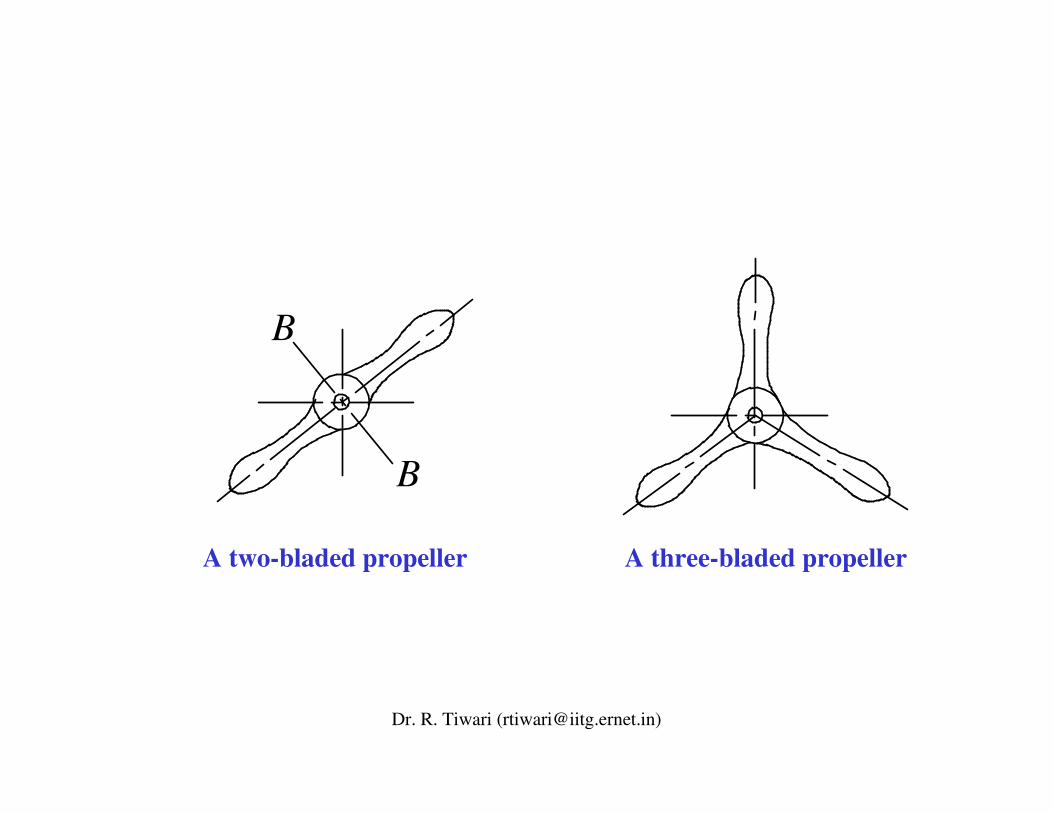
• About a decade latter (1933), the study of asymmetrical shaft systems and asymmetrical rotor systems began.
• The former are systems with a directional in the shaft stiffness and the latter are those with a directional differencein rotor inertia.
• Two-pole generator rotors and propeller rotors are examples of such systems. As these directional differences rotate with the shaft, terms with time-varying coefficientsappear in the governing equations.
• These systems therefore fall into the category of parameterically excited systems, which leads to instability in the rotor system.
Dr. R. Tiwari ([email protected])
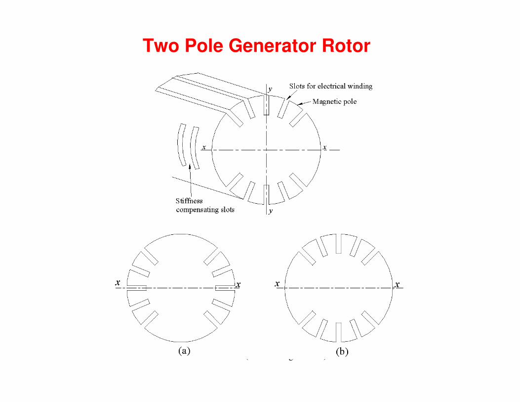
n=1 n=1
n=1
Instability zone
Plot of equation (27) for n = 1
λ
ω
Instability in rotating machines
Dr. R. Tiwari ([email protected])
Dr. R. Tiwari ([email protected])
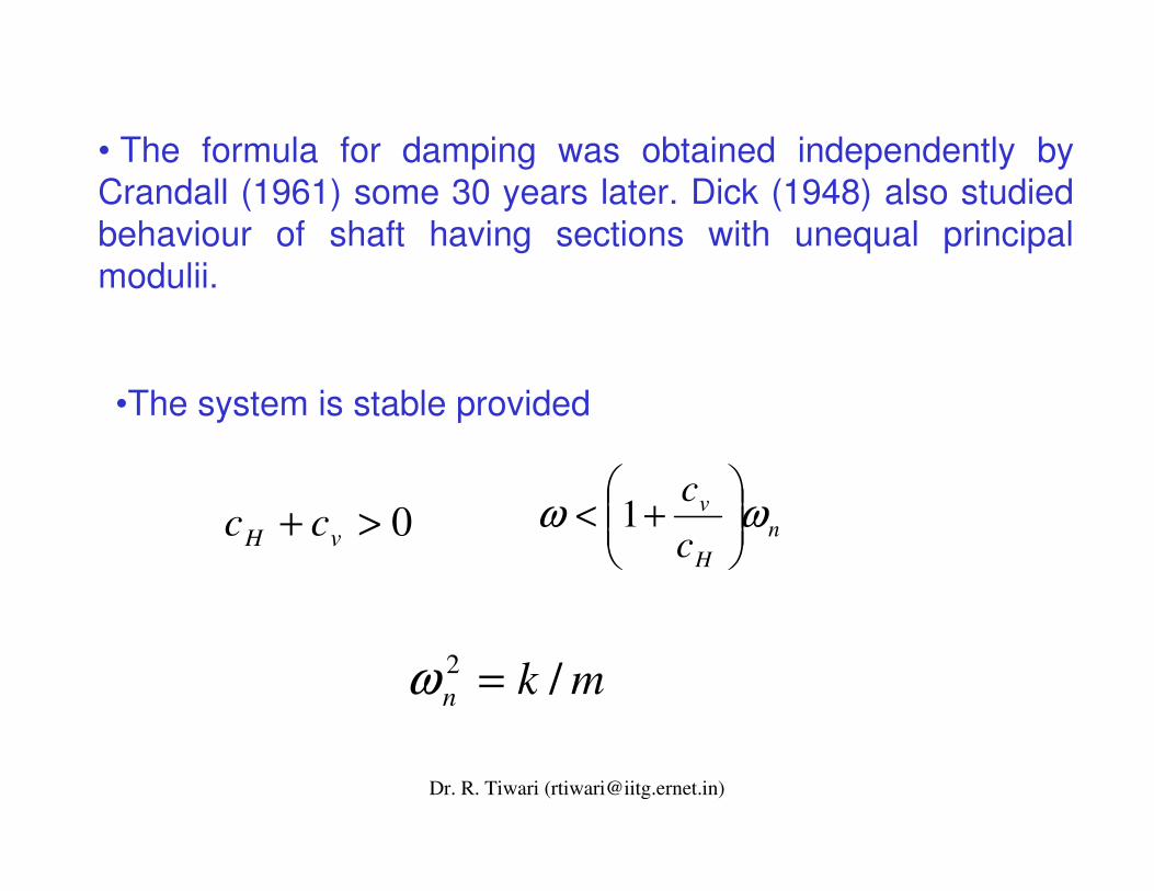
• The most characteristic property of asymmetrical systems is the appearance of unstable vibrations in some rotational speed ranges.
• In 1933, Smith obtained a poineer work in the form of simple formulas that predicted the threshold spin speed for super-critical instability varied with bearing stiffness and with the ratio of external to internal viscous damping.
• To quote from Smith's paper " . . . [the] increase of dissymmetry of the bearing stiffness and in the intensity of [external] damping relative to [internal] damping raises the [threshold] speed . . . and [this threshold] speed is always higher than either critical speed."
Dr. R. Tiwari ([email protected])
• The formula for damping was obtained independently by Crandall (1961) some 30 years later. Dick (1948) also studied behaviour of shaft having sections with unequal principal modulii.
nH
v
cc ωω ���
����
�+< 1
•The system is stable provided
0>+ vH cc
mkn /2 =ω
Dr. R. Tiwari ([email protected])
Thereafter, rotor dynamics expanded to consider various other effects.
As the rotational speed increased above the first critical speed, the huge amount of kinetic energy stored in the rigid-body rotational mode of a high speed rotor is available to fuel a wide variety of possible self-excited vibration mechanisms.
However, the rotor dynamicist's respite from worrying about instability was brief.
In the early 1920s a supercritical instability in built-up rotors was encountered and, shortly thereafter, first shown by Newkirk (1924) and Kimball (1924) to be a manifestation of rotor internal damping (i.e., damping between rotor components).
Dr. R. Tiwari ([email protected])
• Then, Newkirk and Taylor (1925) described an instability caused by the nonlinear action of the oil wedge in a journal bearing, which was named as oil whip.
• Robertson (1932, 1934, 1935a and 1935b ) also studied certain problems of vibratory motion and stability of rotors.
• Baker (1933) described self-excited vibrations due to contact between rotor and stator.
•Kapitsa (1939) ponited out that a flexible shaft could become unstable due to friction conditions in its sliding (bush) bearings.
Dr. R. Tiwari ([email protected])
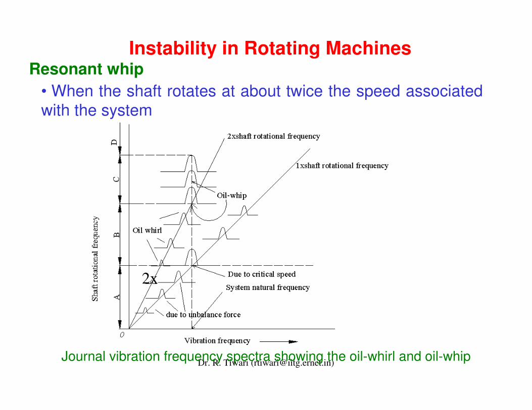
Resonant whip • When the shaft rotates at about twice the speed associated with the system
Journal vibration frequency spectra showing the oil-whirl and oil-whip
Instability in Rotating Machines
2x
Dr. R. Tiwari ([email protected])
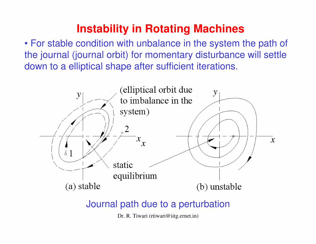
• For stable condition with unbalance in the system the path of the journal (journal orbit) for momentary disturbance will settle down to a elliptical shape after sufficient iterations.
Journal path due to a perturbation
Instability in Rotating Machines
x x
y
x
y
Dr. R. Tiwari ([email protected])
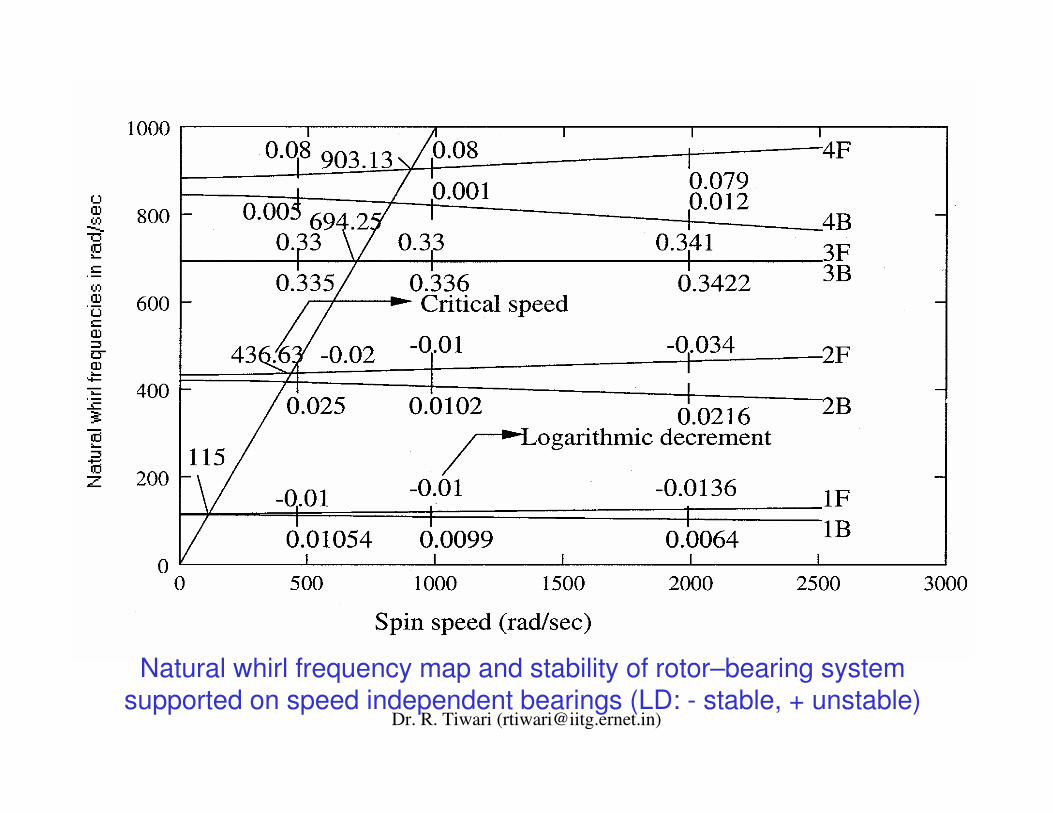
Natural whirl frequency map and stability of rotor–bearing system supported on speed independent bearings (LD: - stable, + unstable)
Dr. R. Tiwari ([email protected])
• Other instabilities have since been discovered. Prominent among these are those due to cross-coupling stiffnesses in bearings and seals and steam whirl (flow in shrouds & shaft seals, and blades), which can also occur in gas turbines.
• These phenomena, in which friction that ordinary damped vibration causes self-excited vibration, attracted the attention of many researchers.
• In the middle of the twentieth century, Hori (1959) succeeded in explaining various fundamental characteristics of oil whip by investigating the stability of shaft motion and considering pressure forces due to oil films.
• The mechanism of vibrations due to the steam whirl in turbines was explained by Thomas (1958) and that in compressors was explained by Alford (1965).
Dr. R. Tiwari ([email protected])
• The vibration of hollow rotor containing fluid is a relatively new problem of flow-induced vibrations.
• Instability due to liquids partially filling interior cavities of rootors was demonstrated by Kollmann (1962) and in 1967 Ehrich reported that fluid trapped in engine-shafts induced asynchronus vibration and also changed the shape of resonance curves.
• Kuipers (1964) and Wolf (1968) independently successed in explaining the appearance of an unstable speed range in a postcritical region of a rotor system containing inviscid fluid.
• In 1980s the rotor dynamic effects of seals in fluid handling machines received a great deal of attention. Rotor destabilization due to seals was predicted and demonstrated in an operational compressor by Jenny (1980).
Dr. R. Tiwari ([email protected])
As rotors became lighter and rotational speeds higher, the occurance of nonlinear resonances such as subharmonics(1/2X, 1/3X, etc.) became a serious problem.
Yamamoto (1955, 1957) studied various kinds of nonlinear resonances after he reported on subharmonic resonance due to ball bearings in 1955. He also investigated combination resonances.
Tondl (1965) studied nonlinear resonances due to oil films in journal bearings.
Ehrich (1966) reported subharmonic resonances observed in an aircraft gas turbine due to strong nonlinearity produced by the radial clearance of squeeze-film dampers. Ehrich (1988, 1992) reported the occurance of various types of subharmonic resonances up to very high order and chaotic vibrations in practical engines.
Dr. R. Tiwari ([email protected])
-2 -1 0 1 2
ωωωωωωωω/2
-2 -1 0 1 2
Backward Forward
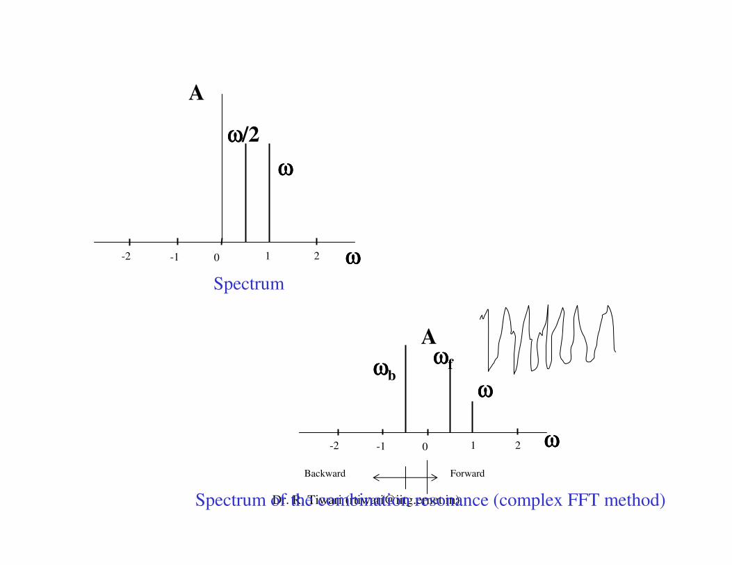
Spectrum of the combination resonance (complex FFT method)
ωωωωfωωωωbωωωω
A
A
ωωωω
ωωωω
Spectrum
Dr. R. Tiwari ([email protected])
Non-stationary phenomena during passage through critical speeds have been studied since Lewis (1932) reported his investigation on the Jeffcott rotor.
Non-stationary phenomena that occur are one in a process with a constant acceleration and another with variable acceleration (limited driving toque). As the theoretical analysis of such transition problems is far more difficult than of stationary oscillations, many of the researchers adopted numerical integrations.
Natanzon (1952) studied shaft vibrations at critical speeds. Grobov (1953, 1955) investigated in general form the shaft vibrations resulting from varying rotational speeds. The development of asymptotic method (analytical) by Mitropol’skii (1965) considerably boosted the research on this subject.
Dr. R. Tiwari ([email protected])
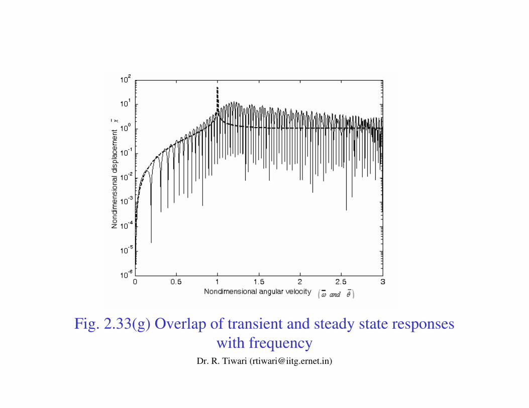
Fig. 2.33(g) Overlap of transient and steady state responses with frequency
Dr. R. Tiwari ([email protected])
• There is an extremely comprehensive literature on the role of fluid-film bearings in rotor dynamics.
• Developments up to 1957 were largely due to Newkirk who explained them in very detailed and graphic way.
• Then, beginning in the early 1960s, most attention focused on hydrodynamic bearings, this was largely stimulated by Lund and Sternlicht (1962) and Lund (1964).
• Gunter’s work (1966) related to rotor dynamic stability problems, combined with Ruhl and Booker’s (1972) and Lund’s (1974) methods for calculating damped critical speeds, stimulated a great deal of interest in rotor-bearing stability problems.
• Lund (1987) gave an overview of the fluid film bearings.
Dr. R. Tiwari ([email protected])
• In the mid 1970s, rotor dynamic instability experiences with various high-pressure compressors and the high-pressure fuel turbo-pump of the Space Shuttle main engine focused a great deal of attention on the influence of fluid-structure-interaction forces, particularly forces due to liquid and gas seals, impellers and turbine.
• Someya (1989) and Tiwari et al. (2004) complied extensive numerical and experimental results and literatures of dynamic parameters of fluid film bearings, respectively.
• Shaft seals have similar effect as fluid-film bearings. They influence the critical speeds, can provide damping or on the other hand cause instability. Some of the first investigations were carried out in 1965 by Lomakin. Since then shaft sealshave acquired a significant role in their effect on rotor dynamics, as the extensive literature shows (Childs, 1993; Tiwari et al., 2005).
Dr. R. Tiwari ([email protected])
• Instability from fluid-film bearings and shaft seals arises from the fact that, during radial displacement of a rotor, a restoring force is produced, which has a component at right angles to this displacement (i.e., a phase of 90 degree).
• Such a mechanism is possible for a rotor with blades, as a result of variable leakage around the blade tips. The phenomenon of instability was described in detail by Newkirk (1924), whose interest was in turbomachineries.
• At first it was thought that the cause was internal friction due to shrink fits on the shaft and a theory was developed to explain this also, together with experimental verification (Newkirk, 1924; Kimball, 1924 and 1925).
Dr. R. Tiwari ([email protected])
Summary of Various Rotor Dynamic Phenomena
Resonance (Th)Dunkerley(1895)
unbalanceCritical speed4
Unbalance response (Th)
Stodola(1924)
gravitySecondary resonance7
Damped unbalance response (Th)
Jeffcott(1919)
unbalanceStable supercritical response
6
Resonance (Exp)Kerr (1916)unbalanceSecond critical speed5
Unbalance response (Th)
Föppl (1895)unbalanceSynchronous whirling
3
Unbalance response (Exp)
De Laval (1983)
unbalanceSelf centering of rotor
2
General motion (Th)
Rankine(1869)
unbalanceWhirling1
RemarksReported/ Interpreted by
Caused byPhenomenaS.N.
Dr. R. Tiwari ([email protected])
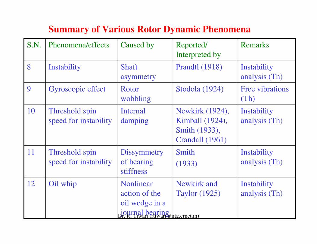
Instability analysis (Th)
Smith (1933)
Dissymmetry of bearing stiffness
Threshold spin speed for instability
11
Instability analysis (Th)
Newkirk and Taylor (1925)
Nonlinear action of the oil wedge in a journal bearing
Oil whip12
Instability analysis (Th)
Newkirk (1924), Kimball (1924), Smith (1933), Crandall (1961)
Internal damping
Threshold spin speed for instability
10
Free vibrations (Th)
Stodola (1924)Rotor wobbling
Gyroscopic effect9
Instability analysis (Th)
Prandtl (1918)Shaft asymmetry
Instability8
RemarksReported/ Interpreted by
Caused byPhenomena/effectsS.N.
Summary of Various Rotor Dynamic Phenomena
Dr. R. Tiwari ([email protected])
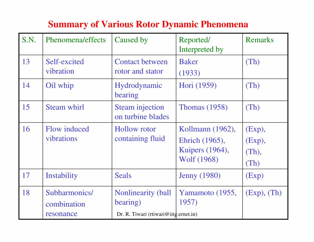
Summary of Various Rotor Dynamic Phenomena
(Exp)Jenny (1980)SealsInstability17
(Exp), (Th)Yamamoto (1955, 1957)
Nonlinearity (ball bearing)
Subharmonics/combination resonance
18
(Exp), (Exp), (Th), (Th)
Kollmann (1962),Ehrich (1965), Kuipers (1964), Wolf (1968)
Hollow rotor containing fluid
Flow induced vibrations
16
(Th)Thomas (1958)Steam injection on turbine blades
Steam whirl15
(Th)Hori (1959)Hydrodynamic bearing
Oil whip14
(Th)Baker (1933)
Contact between rotor and stator
Self-excited vibration
13
RemarksReported/ Interpreted by
Caused byPhenomena/effectsS.N.
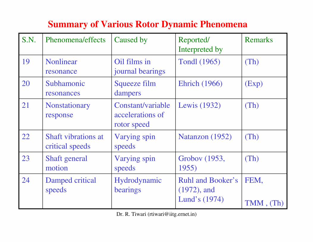
Dr. R. Tiwari ([email protected])
(Th)Grobov (1953, 1955)
Varying spin speeds
Shaft general motion
23
FEM,
TMM , (Th)
Ruhl and Booker’s (1972), and Lund’s (1974)
Hydrodynamic bearings
Damped critical speeds
24
(Th)Natanzon (1952)Varying spin speeds
Shaft vibrations at critical speeds
22
(Th)Lewis (1932)Constant/variable accelerations of rotor speed
Nonstationaryresponse
21
(Exp)Ehrich (1966)Squeeze film dampers
Subhamonicresonances
20
(Th)Tondl (1965)Oil films in journal bearings
Nonlinear resonance
19
RemarksReported/ Interpreted by
Caused byPhenomena/effectsS.N.
Summary of Various Rotor Dynamic Phenomena
Dr. R. Tiwari ([email protected])
Development of Rotor Dynamics Analysis Tools
• In rotor dynamics a remarkable amount can be explained by the dynamics of a single mass Jeffcott rotor model.
• This model, introduced in 1895 by Föppl, was named after Jeffcott, because in 1919 he explained the science of rotor dynamics in a graphic and illuminating way.
• Gradually, the Jeffcott rotor model, in its many variations, came closer to the practical needs of the rotor dynamicists of the day. But, not close enough.
• Vibrations of rotors with continuously distributed mass were studied. The simplest continuous rotor model corresponding to the Euler beam was first studied in the book by Stodola (1924).
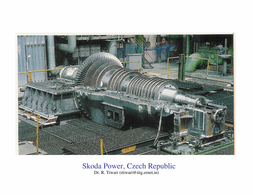
Dr. R. Tiwari ([email protected])Skoda Power, Czech Republic
Dr. R. Tiwari ([email protected])
The critical speeds of shafts with distributed mass were also examined by Grammel (1920, 1929).
In the 1950s and 1960s , Bishop (1959), Bishop and Gladwell (1959), Bishop and Parkinson (1965), Dimentberg (1961) and Tondl (1965) reported a series of papers and books on the unbalance response and the balancing of a continous rotor.
Eshleman and Eubanks (1969) derived more general equations of motion considering the effects of rotary inerta, shear deformation and gyroscopic moment and investigated these effects.
Dr. R. Tiwari ([email protected])
• Many practical rotors, especially those being designed for aircraft gas turbines, were not suitable for a Jeffcott model. For one thing, the distinction between disk and shaft is blurred in the typical aircraft gas turbine.
• In the practical design of rotating machinery, it is necessary to know accurately the natural frequencies, mode shapes and forced responses to unbalances in complex-shaped rotor systems.
• The first systematic procedures for analysizing realistic rotordynamic models, however, gave as much importance to internal forces and moments as they did to displacements.
• The method of Holzer (1921) for torsional vibrations was of this type. Engineers could apply this method using only a slide rule. A more general modeling technique was needed. This was supplied by Prohl in the late 1930s and published in 1945 for crtical speed evaluation of turbine shaft.
Dr. R. Tiwari ([email protected])
• It is similar to the method published about the same time by Myklestad (1944) for the natural frequencies of aircraft wings but was developed independently. Of course, Prohl's method was designed for a rotating structure rather than a stationary one.
• Together, Prohl's and Myklestad's work led to a broader method, now called the Transfer Matrix Method (TMM). This method is particular useful for multi-rotor-bearing systems and has developed rapidily since 1960s by the contribution of many researchers such as Lund et al. (1965, 1967, 1974), Goodwin (1989), and Rao (1996).
• The TMM for rotors remains viable; indeed, it seems still to bethe method of choice for most industrial rotor dynamic analyses. The another representative technique used for this purpose is the finite element method.
Dr. R. Tiwari ([email protected])
• Although most of the concepts used in finite element analysis were described by Courant (1943) the real development of the finite element method as engineering tool occurred a decade later with the introduction of digital computers and the formulation of structural analysis in matrix format (Langefors, 1952; Argyris, 1954; Turner et al., 1956) and then used in various technological fields.
• The name “Finite Element Method” first appeared in the title of a paper by Clough (1960). The first application of the finte element method to a rotor system was made by Ruhl and Booker (1972).
• Then Nelson and McVaugh (1976) generalised it by considering rotary inertia, gyroscopic moment and axial force. It was soon recognised that the large number of nodes necessary to provide accurate stress distribution created dynamic systems too large for economical calculation in 3-D.
Dr. R. Tiwari ([email protected])
Softwares for Rotor Dynamics AnalayisWorld War II can be considered as the demarcation between the early stages of rotor dynamics and what might be called modern rotor dynamics.
This was the consequence of two factors. First, there was a growing awareness of the contributions of rotor dynamicists from non-English speaking countries, e.g., Dimentberg in Russia, Tondl in Czechoslovakia, Kramer in Germany, and Yamamoto in Japan, among many others.
Clearly, after WWII, rotor dynamics had become an international endeavor, a fact that was recognized by the founding of the Rotor Dynamics Committee of the International Federation of the Theory of Machines and Mechanisms (IFToMM). Beginning in 1982, international conferences have been organized by this committee in Rome (1982), Tokyo(1986), Lyon, Chicago, Darmstadt, Sydney and Vienna (2006).
Dr. R. Tiwari ([email protected])
Second, there was a revolution in solution capability; a transition from somewhat simplified models to almost actual geometry.
In the 1960s there was a coalescence of numerical methods applied to structural dynamics and of digital computer capacity that fostered the development of a series of general purpose computer codes.
The initial application of these codes to rotor dynamics was based on the TMM method but in the 1970s another underlying algorithm, the FEM, became available for the solution of the prevailing beam-based models.
Now, in the beginning of the 21st century, rotor dynamicists are combining the FEM and solids modeling techniques to generate simulations that accommodate the coupled behavior of flexible disks, flexible shafts, and flexible support structures into a single, massive, multidimensional model.
Dr. R. Tiwari ([email protected])
Rieger (1974) was first to review the rotor dynamic software on the market at that time. He concluded that “the development of rotor dynamics programs has lacked the support afforded to other areas of structural mechanics”.
Crandall (1992) gave an overview of the rotordynamic compluter codes (e.g. ANSYS, CADENSE, MADYN, RODYN, ROMAC, SAMCEF, VT-FAST, etc.). The classical Jeffcott rotor with four degrees of freedon was used to illustrate free, forced and self-excited vibration problems for rotordynamic systems. He also concluded that with regards to quality and quantity of software the specialised area of rotor dynamics still lags behind the broader field of non-rotating structural dynamics. He gave two main reasons for this that “the rotor dynamics market is smaller and the technical problems are more difficult”.
Dr. R. Tiwari ([email protected])
Dynamic Balancing of Rotors• The most important and fundamental procedure to reduce unfavourable vibrations is to eliminate geometric imbalance in the rotor. The balancing procedure for a rigid rotor was established relatively early.
• A practical balancing machine based on this technique was invented in 1907 (Miwa and Simomura, 1976). The arrival of high-speed rotating machins made it necessary to develop a balancing technique for flexible rotors.
• Two representative theories were proposed. One was the modal balancing method proposed in the 1950s by Federn (1957) and Bishop and Gladwell (1959). The other is the influence coefficient method proposed in late 1930s by Rathbone (1929) and later by Thearle (1932) and developed mainly in the Unites States along with the progress of computers and instruments for vibration measurements (Wowk, 1995).
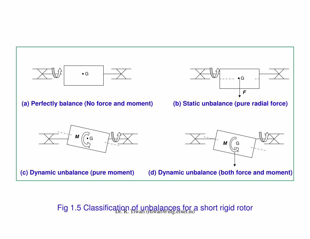
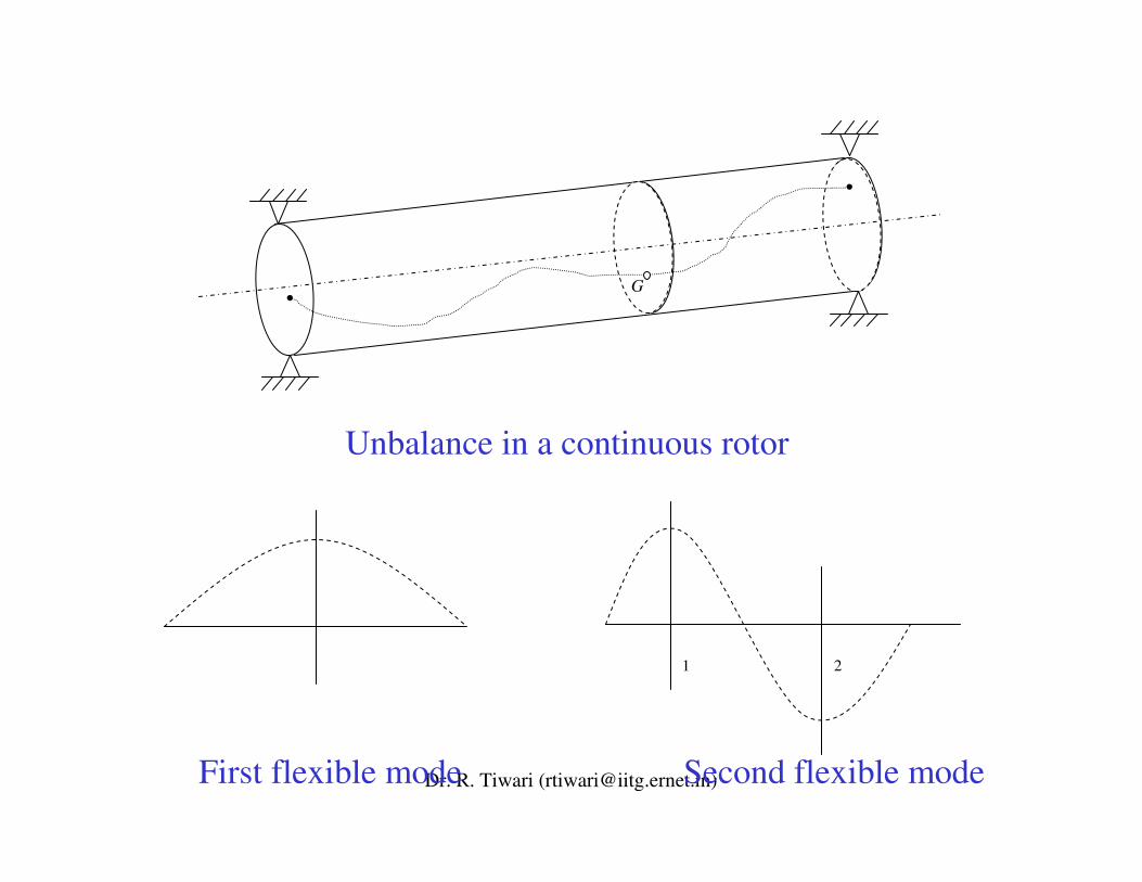
Dr. R. Tiwari ([email protected])Fig 1.5 Classification of unbalances for a short rigid rotor
F
• G
• GM• GM
• G
(a) Perfectly balance (No force and moment) (b) Static unbalance (pure radial force)
(c) Dynamic unbalance (pure moment) (d) Dynamic unbalance (both force and moment)
Dr. R. Tiwari ([email protected])
G
1 2
First flexible mode Second flexible mode
Unbalance in a continuous rotor
Dr. R. Tiwari ([email protected])
Condition Monitoring of Rotating Machineries
In the 1960s, cracks were found in rotors of some steam turbines. To prevent serious accidents and to develop a vibration diagnostis system detecting cracks, research on vibrations of cracked shafts begun.
In the 1970s, Gasch (1976) and Henry and Okah-Avae (1976) investigated vibrations giving consideration to nonlinearity in stiffness due to open-close mechanisms. They showed that an unstable region appeared or disappeared at the critical speed, depeending on the direction of the unbalance.
Dr. R. Tiwari ([email protected])
• An other area in which lot of development took place is on assessment of turbomachinery condition monitoring and failure prognosis technology.
• High-performance turbomachines are now extremely important elements of worldwide industry. The electric power, petrochemical, mining, marine, and aircraft industries are primeexamples for which turbomachinery is crucial to business success.
• Failure and resulting downtime can be very costly to the industry involved (Rieger et al., 1990).
• According to Eshleman (1990), over the past several years, instrumentation and monitoring capabilities have increased dramatically, but techniques for fault diagnosis have evolved slowly.
Dr. R. Tiwari ([email protected])
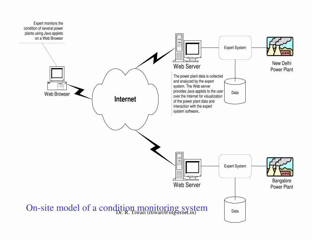
Internet
Web Server
Data
Expert System
Web Browser
Expert monitors thecondition of several powerplants using Java applets
on a Web Browser
The power plant data is collectedand analyzed by the expertsystem. The Web serverprovides Java applets to the userover the Internet for visualizationof the power plant data andinteraction with the expertsystem software..
Web Server
Data
Expert System
New DelhiPower Plant
BangalorePower Plant
On-site model of a condition monitoring system
Dr. R. Tiwari ([email protected])
• The tools are therefore still more advanced than the techniques, and there are three technical areas that must be addressed for effective fault diagnosis using vibration: condition and fault mechanism, modification of signal trasmission paths, and signal analysis.
• Edward et al. (1998) provided a broad review of the state of the art in fault diagnosis techniques, with particular regard torotating machinery. A detailed review of the subject of fault diagnosis in rotating machinery was then presented. Special treatment was given to the areas of mass unbalance, bowed shafts and cracked shafts, these being amongst the most common rotor-dynamic faults.
Dr. R. Tiwari ([email protected])
• Vibration response measurements yield a great deal of information concerning any faults within a rotating machine, and many of the methods utilising this technique are reviewed.
• Pusey and Roemer (1999) provided a broad overview of developments and progress in condition monitoring, diagnostic and failure prognosis technology applicable to high-performance turbomachineries.
Dr. R. Tiwari ([email protected])
• Cracks in shafts have long been identified as factors limiting the safe and reliable operation of turbomachines.
• They can sometimes result in catastrophic failure of equipment (rotor bursts) and, more often, in costly process upsets, repairs and premature scrapping and replacement of equipment. In the past three decades, much research and many resources have gone into developing various on-line and off-line diagnostic techniques to effectively detect cracks before they cause serious damage.
• Sabnavis et al. (2004) reviewed literature on cracked shaft detection and diagnostics published after 1990.
• One of the earliest documented applications of acoustic emission technology (AET) to rotating machinery monitoringwas in the late 1960s.
Dr. R. Tiwari ([email protected])
• Since then, there has been an explosion in research- and application-based studies covering bearings, pumps, gearboxes, engines, and rotating structures.
• Mba and Rao (2006) presented a comprehensive and critical review on the application of AET to condition monitoring and diagnostics of rotating machinery.
Dr. R. Tiwari ([email protected])
Recent Trends
• The latest topic in rotor dynamics is a study of magnetic bearings (a mechtronics product) (Schweitzer et al., 2003; Chiba, et al., 2005), which support a rotor without contacting it and active dampers.
• This study has received considerbale attention since Schweitzer reported his work in 1975. We are now a long way from the approaches of Jeffcott and Prohl, a journey that deserves its own history sometime.
Dr. R. Tiwari ([email protected])
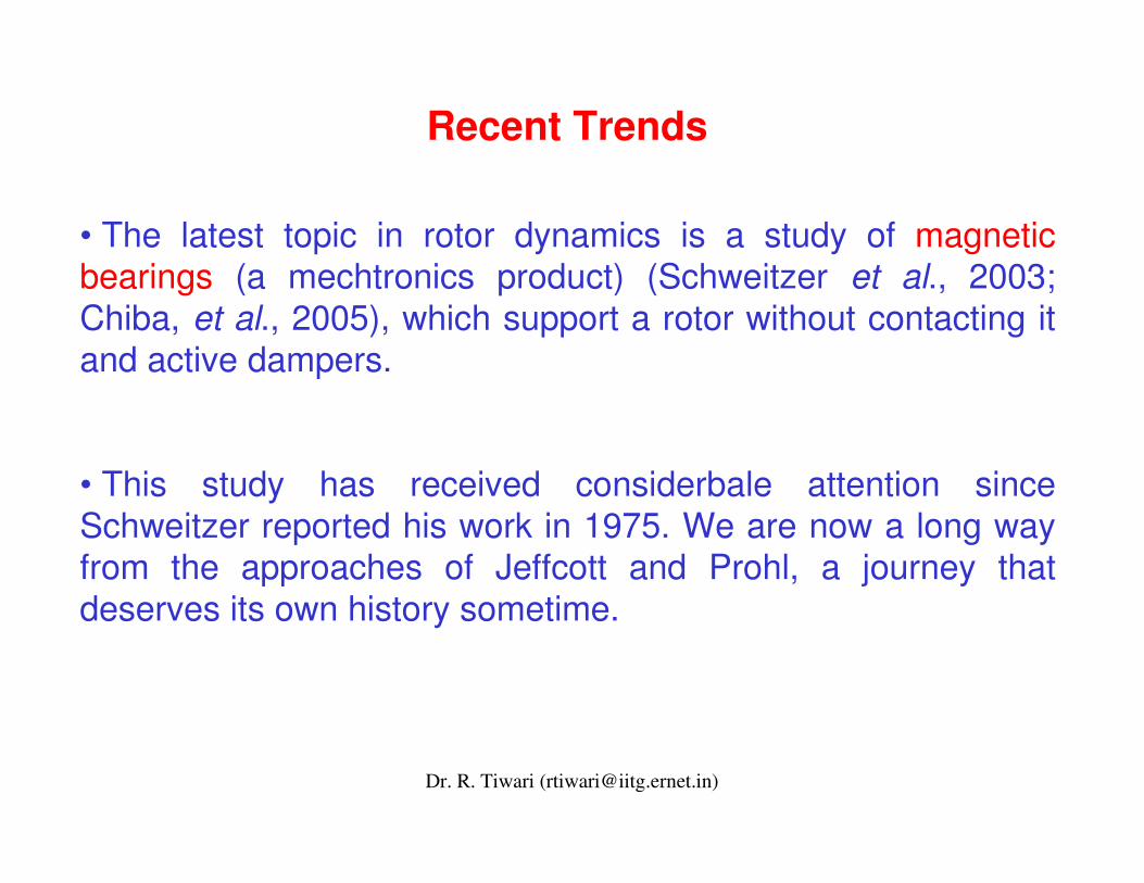
Bearing bush
Outer raceway of rolling bearing (can displace radially and constraint not to rotate.
Squeeze film
Rotor
Oil feed groove
Schematic diagram of squeeze film (passive) dampers
Dr. R. Tiwari ([email protected])
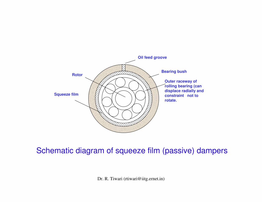
Rotor
Rolling bearing
Electrodes
Teflon
Smart (active) fluid-film dampers
Dr. R. Tiwari ([email protected])
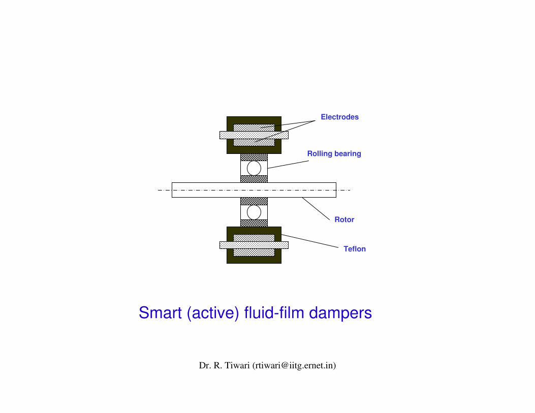
Working principle of active magnetic bearing
Rotor
Electro magnet
SensorController
Power Power AmplifierAmplifier
ff
Dr. R. Tiwari ([email protected])
Main Advantages Active Magnetic Bearings
• Magnetic bearings allow contact-free motions, which results in
Absence of lubrication and seals.
Low bearing frictional losses.
Absence of mechanical wear.
• High speeds whose limit is the strength of the material of the rotor.
Dr. R. Tiwari ([email protected])
• Online balancingOnline balancing is possible.is possible.
•• Adaptable stiffness and dampingAdaptable stiffness and damping properties and this properties and this characteristic can be utilized in vibration isolation:characteristic can be utilized in vibration isolation:
Passing critical speeds with less vibration amplitudes.Passing critical speeds with less vibration amplitudes.
Stabilization of the rotor systems when they are exposedStabilization of the rotor systems when they are exposedto excitations such as earth quakes etc. to excitations such as earth quakes etc.
Eliminating stability zones.Eliminating stability zones.
Dr. R. Tiwari ([email protected])
• Research in rotor dynamics is aimed at improving the understanding of rotor dynamic phenomena and improving the performance of rotating machinery.
• In most rotor dynamic systems the vibratory amplitudes are sufficiently small that linear analysis of rotor and stator deformations are satisfactory.
• In rotor dynamics structural modelling is generally adequate and most research is centered on fluid-structure interactions: bearings, seals, blade forces, squeeze-film dampers etc. It is here that the nonlinearities are concentrated.
Conclusions
Dr. R. Tiwari ([email protected])
• The equations of motion of such systems consist of a great many linear equations coupled to a small handful of nonlinear equations (Yamamoto and Ishida, 2001).
• The most promising area of research for performance improvement is active control.
• I believe that it is not an easy matter to present a good and enough complete history of rotor dynamics because there exists an enormous number of publications in different non-English languages (European, Russian, Japanese, etc.) .
Conclusions
Dr. R. Tiwari ([email protected])
• Of course, it would be possible to mention some problems and phenomena not commonly occurring in rotor systems, e.g. special stability problems (e.g. investigation the stability in the large – domains of attraction), the effect of the tuning the system into the internal resonance, mutual effect of lateralwith torsional/axial vibrations, effect of the limited source of energy, etc.
Conclusions