rotary actuators - phd, inclitstore.phdinc.com/pdf.asp?filename=m30_ec.pdf · air/oil tandem rotary...
TRANSCRIPT

Specialty Actuators Provide Solutions toUnique Rotary Motion Requirements
M30-EC
ROTARY ACTUATORS

2 ORDERING DATA: SERIES 1000-8000 ROTARY ACTUATORS
PORT CONTROL©
BUILT-IN METER OUTFLOW CONTROL VALVE
P - Flow control both directionsP1 - Flow control clockwiseP2 - Flow control counterclockwise
R1 6 A - P180 - D K-M-V- -A2
NOTES:1) Sensor must be used with a PHD Set Point Module.
See Switches and Sensors section for informationand ordering data.
2) Mounting flanges must be ordered separately.
SERIES1000 & 20003000 & 40005000 & 60007000 & 8000
PROXIMITY SWITCHMOUNTING BRACKETS
SIZE NO.-32-34-38-39
See Switches and Sensorssection for completeordering information.
ANGLE OF ROTATIONSTANDARD ANGLES
45°, 90°, 180°, 270°, 360°, and 450°For other available rotations,
consult PHD.
(Cushions and Shock Pads arenot available on the same end ofactuator. Shock Pads are notavailable for Hydraulic use.)
CUSHION OR SHOCK PADD - Cushions both directionsD1 - Cushion clockwiseD2 - Cushion counterclockwiseB - Shock Pads both directionsB1 - Shock Pad clockwiseB2 - Shock Pad counterclockwise
OPTIONSE - Magnetic Piston for Hall Effect SwitchI - Port Position 1 on top rack
Port Position 3 on bottom rack(Available on Series 2000, 4000, 6000, and 8000 only.)
M - Magnetic Piston for Reed SwitchO - Ports in Position 1*Q - Ports in Position 3*T - Ports in Position 4V - Fluoro-Elastomer SealsW - Close Tolerance Rotation, +30 minutes, -0Z1 - Electroless Nickel Plate
* Available on Series 1000, 3000, 5000, and 7000 only.
ANGLE ADJUSTMENTA - Angle adjustment both endsA1 - Angle adjustment clockwise 30°A2 - Angle adjustment counterclockwise 30°
(20° for Series 8000)
SERIES1 (000) 1" Bore Single Rack2 (000) 1" Bore Double Rack3 (000) 1-3/8" Bore Single Rack4 (000) 1-3/8" Bore Double Rack5 (000) 2" Bore Single Rack6 (000) 2" Bore Double Rack7 (000) 3" Bore Single Rack8 (000) 3" Bore Double Rack
DESIGN NO.6 - Metric - Ports and mounting holes, pinion
shafts and keyway are metric.
TYPEMETRIC
R16A - Single Shaft Ext.10 bar Air Max.
R26A - Double Shaft Ext.10 bari Air Max.
R16H - Single Shaft Ext.100 bar Hyd. Max.
R26H - Double Shaft Ext.100 bari Hyd. Max.
UNITS WITH METRIC SHAFTS AND KEYWAYTO ORDER SPECIFY:Type, Design No., Series, Angle of Rotation, and Options.
INDEX:Series 1000-8000
Pages 2 to 4
Air/Oil TandemPages 5 to 8
Multi-PositionPages 9 to 13
Engineering DataPages 14 to 16
Plumbing Schem
aticsPages 17 and 18
Start-up ProcedurePage 19
OptionsPages 20 to 24
© Copyright 1998, by PHD, Inc. Printed in the U.S.A.

3
ROTARY ACTUATORS: SERIES 1000-8000
TYPESPECIFICATIONS R1xA & R2xA R1xH & R2xHPISTON SEALS (3 Per Piston) Block Vee with Back-up RingPISTONS Free Floating AluminumTIERODS High Tensile SteelTUBE SEALS Square CutPINION SHAFTS One Piece Alloy SteelRACK Alloy SteelEND CAPS Zinc Plated Alloy SteelBODY Hardcoated AluminumTUBES Hardcoated Aluminum Hardcoated Aluminum on Series 1000-4000
— Honed Steel on Series 5000-8000BEARINGS (2) Steel Ball BearingsPORTS NPT [BSP]LUBRICATION Permanent for Non-Lube Air —
150 psi [10 bar] Air Max 1500 psi [100 bar] Hyd. Max.STANDARD ROTATIONS 45°, 90°, 180°, 270°, 360°, 450°OPTIONS Port Controls®, Cushions, Angle Adjustment,
Magnetic Pistons, Fluoro-Elastomer Seals
THEORETICAL TORQUE in-lb/psi [Nm/bar]SERIES
1000 2000 3000 4000 5000 6000 7000 8000.38 .77 1.1 2.2 2.3 4.7 10.6 21.2
[.63] [1.28] [1.83] [3.66] [3.82] [7.82] [17.61] [35.21]
OUTPUT TORQUES TO 31,800 in-lb [3595 Nm]
BENEFITS
■ PHD Series 1000-8000 Rotary Actuators are pneumatically orhydraulically powered providing output torques up to31,800 in-lb [3595 Nm].
■ Rugged design and construction makes these actuators idealfor heavy duty service in tough working environments.
■ Four bore sizes are available in single and double rack modelswith standard rotations from 45° to 450°.
■ Free floating pistons with rack and pinion design eliminatesbinding for low breakaway and long unit life.
■ Sealed shaft ball bearings provide long life and maximum shaftstability for heavy payloads.
■ Available with a wide range of options including built-in flowcontrols, cushions, angle adjustments, shock pads, and pinionshaft options for specifying the exact actuator for yourapplication.
■ Simple construction allows easy field repairability.

4 DIMENSIONS: SERIES 1000-8000 ROTARY ACTUATORS
All dimensions are reference only unless specifically toleranced.
METRIC
SERIES1000 & 20003000 & 40005000 & 60007000 & 8000
LETTER DIMENSIONV
12.69/12.7122.22/22.2328.55/28.5844.42/44.45
W3.15 x 1.59 x 164.75 x 2.36 x 386.35 x 3.18 x 389.53 x 2.36 x 78
QUICK REFERENCE FOR: A + (T° x B)
SERIES1000 & 20003000 & 40005000 & 60007000 & 8000
DEGREE OF ROTATION
PORT PRESSURIZED - FULL CCW POSITIONC1 ON SERIES 1000, 3000, 5000, & 7000
OR C1 & E ON SERIES 2000, 4000, 6000, & 8000
PORT PRESSURIZED - FULL CW POSITIONC2 ON SERIES 1000, 3000, 5000, & 7000OR C2 & A ON SERIES 2000, 4000, 6000, & 8000
OPTION LOCATION REFERENCELETTER OPTION
REFERENCED BY TUBE NUMBERACTUATOR
TYPER1xA & R2xAR1xH & R2xH
PORT & NEEDLE LOCATIONSREFERENCED BY CIRCLED NUMBERS
-A1IIII
-A2II
-A-D1IIII
-D2II
-D-M
I & III & II
-EI & III & II
-TPORT
44
-P11
-D11
-QPORT
33
-P22
-D22
-OPORT
11
-P22
-D22
-B1II—
-B2I
—
-B-P1IIII
-P2II
-P-N
I & IIN/A
STANDARDPORT
22
-P11
-D11
V12.00/11.9722.00/21.9628.00/27.9644.00/43.96
W4 x 2.5 x 156 x 3.5 x 328 x 5 x 4012 x 5 x 56
SPECIFIED BY R2xxWHEN ORDERING
PA
U
O
Q
R
TAS
V DIA
W KEYWAY
M THREAD4X EACH FRONT,BACK & BOTTOM
+.025-.000 DIANB
A + (T° x B)Y + (T° x Z)
ZA MAX
HF
G
JA
C
C/2 L KA SQ
X BSPOPTIONALANGLE ADJUSTMENT
ED
I II
IVIII
ZA MAX
C1
A
C2
E
NB28.58 x 1.4 DP50.80 x 1.0 DP55.00 x 1.3 DP85.00 x 3.0 DP
SHAFT KEYWAY: SHOWN AT MID-ROTATIONPORT POSITION: INDICATED BY CIRCLED NUMBERS -O & -Q AVAILABLE ON SERIES 1000, 3000, 5000, & 7000 ONLYTUBES III & IV: INCLUDED ON SERIES 2000, 4000, 6000, & 8000 UNITS ONLYMTG. HOLES: CENTERED ON CENTERLINE OF ACTUATOR BODYCUSHIONS: SERIES 1000 & 2000 ACTUATORS ADD 13 mm TO RESPECTIVE “A” AND “Y” DIMENSIONS FOR EACH CUSHION
4
3
2
2
3
4
1
I II
T°
A145201232302
B0.440.660.661.33
C76
108127203
D5176
102127
E38.150.863.576.2
F69
1012
G13171927
H06511
JA19292948
KA35485789
L36535892
O50.876.276.2127.0
PA22484889
Q50.876.288.9127.0
R13161938
S6131332
TA38.150.850.863.5
U8
141019
Y72
100116154
Z0.220.330.330.66
ZA29384873
MM6 x 1.0 x 8M8 x 1.0 x 13M10 x 1.5 x 16M20 x 2.5 x 32
45164.6230.5261.5368.3
90184.5260.2291.1427.7
180224.3319.7351.4548.0
270264.1379.1350.7546.6
360303.8438.6469.5784.4
450343.6498.0529.0903.2
IMPERIAL SHAFTS* METRIC SHAFTS*
* BOTH IMPERIAL AND METRIC SHAFT OPTIONS AVAILABLE ON METRIC BODY (IMPERIAL SHAFT = DESIGN 5, AND METRIC SHAFT = DESIGN 6). NUMBERS ARE FOR METRIC UNITS AND ARE IN mm.

5
ORDERING DATA: AIR/OIL TANDEM ROTARY ACTUATORS
R1 9 R - 90180 - D M-V
TO ORDER SPECIFY:Type, Design Nol., Series,Angle of Rotation, and Options.
- -A2
SERIES2 (000) 1" Bore Double Rack4 (000) 1-3/8" Bore Double Rack6 (000) 2" Bore Double Rack8 (000) 3" Bore Double Rack (Oil Section is 2" Bore)
NOTE: Sensor must be used with a PHD SetPoint Module. See Switches and Sensors sectionfor information and ordering data.
-3
CUSHIOND - Cushions both directionsD1 - Cushion clockwiseD2 - Cushion counterclockwise
ANGLE ADJUSTMENTA - Angle adjustment both endsA1 - Angle adjustment clockwise 30°A2 - Angle adjustment counterclockwise 30°
PORT CONTROL©
BUILT-IN METER OUTFLOW CONTROL VALVE
Port Control is standard onall Air/Oil Tandem Actuators.
SIZE NO.-32-34-38-39
See Switches and Sensorssection for completeordering information.
PROXIMITY SWITCHMOUNTING BRACKETS
SERIES2000400060008000
ANGLE OF ROTATIONFROM POSITION I
TO POSITION IIUse this digit for 3
Position Tandems only.
OPTIONSE - Magnetic Piston for Hall Effect SwitchI - Port Position 1 top rack
Port Position 3 bottom rackM - Magnetic Piston for Reed SwitchT - Port in Position 4V - Fluoro-Elastomer SealsW - Close Tolerance Rotation, +30 minutes, -0Y - Tandem Cap rotated 180°Z1- Electroless Nickel Plate
ANGLE OF ROTATIONSTANDARD ANGLES45°, 90°, 180°, 270°,
360°, and 450°For other available
rotations, consult PHD.
3 ROTARY POSITIONSUse this digit for 3
Position Tandems only.
TYPER19R - Single Shaft Ext.
Air/Oil TandemR29R - Double Shaft Ext.
Air/Oil Tandem
UNITS WITH METRIC SHAFTS AND KEYWAY
DESIGN NO.9 - Metric - Ports, mounting holes, pinon
shaft and keyway are metric.
METRIC

6
AIR/OIL TANDEM ROTARY ACTUATORS:SERIES 2000-8000
A
B
OPERATING PRINCIPLEThis feature is available on Series 2000, 4000, 6000,
and 8000. One end functions as a control member only,reducing the effective output torque to match 1000, 3000,5000, and 7000 respectively.
The illustration shows a Tandem Actuator with built-inPort Controls®, crossover manifold and oil reservoir. Thelatter serves as an accumulator to compensate for oilvolume changes due to temperature variation.
NOTE: The Reservoir should have 20 psi [1.3 bar]pressure at all times to ensure the system remains purged.
OUTPUT TORQUES TO 1,590 in-lb [179 Nm]
THEORETICAL TORQUE in-lb/psi [Nm/bar]SERIES
2000 4000 6000 8000.38 1.1 2.3 10.6
[.63] [1.83] [3.62] [17.61]
BENEFITS
■ PHD Air/Oil Tandem Actuators provide smooth consistentrotary motion even at low speeds for applications requiringpositive control of payload.
■ Design provides simplicity and economics of air power with thesmooth control of hydraulics.
■ Oil transfer is accomplished through a one-piece tandem capeliminating external crossovers.
■ Four bore sizes are available in both 2 and 3 position modelswith standard rotations up to 450° to fit a variety ofapplication requirements.
■ Built-in flow controls are standard for precise control ofrotation speed.
■ Free floating pistons with rack and pinion design eliminatebinding for low breakaway and long unit life.
■ Sealed shaft ball bearings provide long life and maximum shaftstability for heavy payloads.
■ Available with a wide range of options including cushions,angle adjustments, shock pads, and pinion shaft options forspecifying the exact actuator for your application.
■ Simple construction allows easy field repairability.
SPECIFICATIONS R1xR & R2xRPISTON SEALS (3 Per Piston) Block Vee with Back-up RingPISTONS Free Floating AluminumPINION SHAFTS One Piece Alloy SteelRACK Alloy SteelEND CAPS Zinc Plated SteelBODY Hardcoated AluminumTUBES Hardcoated Aluminum on Air side, Honed Steel on Oil sideBEARINGS Two Steel Ball BearingsPORTS NPT [BSP]LUBRICATION Permanent for Non-Lube AirWORKING PRESSURE 150 psi [10 bar] Air Max.STANDARD ROTATIONS 45°, 90°, 180°, 270°, 360°, 450°OPTIONS Cushions, Angle Adjustments, Magnetic Pistons,
Fluoro-Elastomer Seals (Port Controls® are standard)HYDRAULIC FLUID Rykon 32 (Viscosity at 100°F [38°C] is 158 SSU; at 250°F [126°C] is 45.1)

7
XG1/8G1/4G1/4G3/8
Y72100116154
Z0.220.330.330.66
ZA29384873
LETTER DIMENSION
QUICK REFERENCE FOR: A + (T° x B)DEGREE OF ROTATION
SERIES2000400060008000
SERIES2000400060008000
A158203233283
B0.440.660.661.32
C76108127203
D5176102127
E38.150.863.576.2
F691012
G13171927
H06511
JA19292948
KA35485789
L36535892
LA73
106119156
LB44707076
O50.876.276.2
127.0
PA22484889
Q50.876.288.9127
R13161938
S6
131332
TA38.150.850.863.5
U28141019
MM6 x 1.0 x 8
M8 x 1.0 x 13M10 x 1.5 x 16M20 x 2.5 x 32
U133325
45177.7232.6263.1342.1
90197.6262.2292.9401.5
180237.4321.7352.3520.4
270277.2381.2411.7639.3
360317.0440.6471.2758.1
450356.7500.0530.9877.0
NB28.58 X 1.450.80 X 1.055.00 X 1.385.00 X 3.0
V12.69/12.7122.22/22.2328.55/28.5844.42/44.45
W3.15 x 1.59 x 164.75 x 2.36 x 386.35 x 3.18 x 389.53 x 2.36 x 78
V12.00/11.9722.00/21.9628.00/27.9644.00/43.96
W4 x 2.5 x 156 x 3.5 x 328 x 5 x 4012 x 5 x 56
RESERVOIR ASSEMBLY IS INCLUDED WITH UNIT.DIMENSIONAL DATA IS IN AIR/OIL & RESERVOIR SECTION 10.SERIES 2000, 4000, & 6000 UNITS USE PART NO. 13459-03-x.SERIES 8000 UNITS USE PART NO. 13459-02-x.
NOTE: THE RESERVOIR SHOULD HAVE 1.4 bar PRESSURE AT ALL TIMESTO ENSURE THE SYSTEM REMAINS PURGED.
2X PORT CONTROLS
CHECK VALVEFITTING
SPECIFIED BY R2xRWHEN ORDERING
U1
PAU2
LB
O
Q
R
TAS
V DIA
W KEYWAY2X BLEED PLUGS
M THREAD4X EACH FRONT,BACK & BOTTOM
LA/2
LA
2.125.4+.025-.000 DIANB
A + (T° x B)Y + (T° x Z)
ZA MAX
HF
G
JA
C
C/2L
KA SQ
2XX BSP
OPTIONALANGLE ADJUSTMENT
ED
I II
IVIII
C2
E
T°
PORT PRESSURIZED - C2FULL CW POSITION
PORT PRESSURIZED - EFULL CCW POSITION
I II
OPTION LOCATION REFERENCELETTER OPTION
REFERENCED BY TUBE NUMBER
-A1III
-A2I
-A -P
STANDARD-M
I & III-E
I & III
-TPORT
4-P4
-D4
STANDARDPORT
2-P4
-D4
PORT & NEEDLE LOCATIONSREFERENCED BY CIRCLED NUMBERS
-D1II
-D2IV
-D-P1 -P2
ACTUATORTYPE
R1xR & R2xR
SHAFT KEYWAY: SHOWN AT MID-ROTATIONPORT POSITION: INDICATED BY CIRCLED NUMBERSMTG. HOLES: CENTERED ON CENTERLINE OF ACTUATOR BODY
42
2
3
4
1
IMPERIAL SHAFTS* METRIC SHAFTS*
* BOTH IMPERIAL AND METRIC SHAFT OPTIONS AVAILABLE ON METRIC BODY (IMPERIAL SHAFT = DESIGN 8, AND METRIC SHAFT = DESIGN 9). NUMBERS FOR METRIC UNITS AND ARE IN mm.
DIMENSIONS: AIR/OIL TANDEM
ROTARY ACTUATORS
METRIC
All dimensions are reference only unless specifically toleranced.

8
ZA MAX
F
H NB +.025-.000 DIAG YB + (T° x Z)
Y + ( T° x Z )
M THREAD4X EACH FRONT,BACK & BOTTOM
ED
4XX BSP
C/2
C
L
JA
KA SQ SPECIFIED BY3R2xR WHENORDERING
S TA
Q
O
U1
PA
W KEYWAY
V DIA
R
FA
GA
YA + Z (T° + J°)
YA + Z (T° + K)
V
VI
U2
RESERVIOR ASSEMBLY IS INCLUDED WITH UNIT.DIMENSIONAL DATA IS IN AIR/OIL & RESERVOIR SECTION 10.SERIES 2000, 4000, & 6000 UNITS USE PART NO. 13459-03-x.SERIES 8000 UNITS USE PART NO. 13459-02-x.
NOTE: THE RESERVOIR SHOULD HAVE 1.4 BAR PRESSURE AT ALL TIMESTO ENSURE THE SYSTEM REMAINS PURGED.
25.4 2.1
LA
LA/2
2X BLEED PLUGS
SHAFT KEYWAY: SHOWN AT MID-ROTATIONPORT POSITIONS: INDICATED BY CIRCLED NUMBERSMTG. HOLES: CENTERED ON CENTERLINE OF ACTUATOR BODYPLUMBING SCHEMATIC: L0CATED IN ENGINEERING DATA SECTION
I II
III IV
LB
CHECK VALVEFITTING
2X PORT CONTROLS1
4
4
3
2
2
OPTION LOCATION REFERENCELETTER OPTION
REFERENCED BY TUBE NUMBERACTUATOR
TYPE3R1xR & 3R2xR
-D1II
-D2IV
-D -MI & IIIV & VI
-EI & IIIV & VI
PORT & NEEDLE LOCATIONSREFERENCED BY CIRCLED NUMBERS
-ASTANDARD
-P
STANDARD-P1 -P2
-TPORT
4-P4
-D4
STANDARDPORT
2-P4
-D4
LETTER DIMENSION
SERIES2000400060008000
C76108127203
D5176
102127
E38.150.863.576.2
F69
1012
G13171927
H065
11
JA19292948
KA35485789
L36535892
O50.876.276.2
127.0
PA22484889
Q50.876.288.9127.0
R13161938
S6
131332
TA38.150.850.863.5
U28
141019
XG1/8G1/4G1/4G3/8
Y85102118128
Z0.220.330.330.66
ZA29384873
MM6 x 1.0 x 8M8 x 1.0 x 13M10 x 1.5 x 16M20 x 2.5 x 32
FA1310912
GA19181827
U1333
25
YA145171186251
YB6685
101133
LA73.0106.4119.1155.6
LB44.569.969.976.2
NB28.58 x 1.4 DP50.80 x 1.0 DP55.00 x 1.3 DP85.00 x 3.0 DP
V12.69/12.7122.22/22.2328.55/28.5844.42/44.45
W3.15 x 1.59 x 164.75 x 2.36 x 386.35 x 3.18 x 389.53 x 2.36 x 78
V12.00/11.9722.00/21.9628.00/27.9644.00/43.96
W4 x 2.5 x 156 x 3.5 x 328 x 5 x 4012 x 5 x 56
C2
E
D1
D2
OPTIONALANGLE ADJUSTMENT
IIII
PORTS PRESSURIZEDD1 & D2
II
PORT PRESSURIZED - EFULL CCW POSITION
PORT PRESSURIZED - C2
FULL CW POSITION
T°
K°J°
IMPERIAL SHAFTS* METRIC SHAFTS*
* BOTH IMPERIAL AND METRIC SHAFT OPTIONS AVAILABLE ON METRIC BODY (IMPERIAL SHAFT = DESIGN 8, AND METRIC SHAFT = DESIGN 9). NUMBERS FOR METRIC UNITS AND ARE IN mm.
DIMENSIONS: 3 POSITION AIR/OIL TANDEM
METRIC
All dimensions are reference only unless specifically toleranced.
9
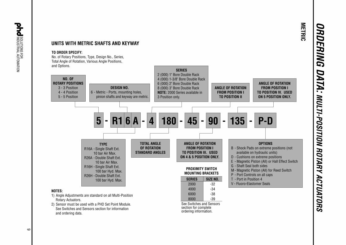
ORDERING DATA: MULTI-POSITION ROTARY ACTUATORS
- 90180 - P-D
TO ORDER SPECIFY:No. of Rotary Positions, Type, Design No., Series,Total Angle of Rotation, Various Angle Positions,and Options.
TOTAL ANGLEOF ROTATION
STANDARD ANGLES
-
ANGLE OF ROTATIONFROM POSITION I
TO POSITION II
4
SERIES2 (000) 1" Bore Double Rack4 (000) 1-3/8" Bore Double Rack6 (000) 2" Bore Double Rack8 (000) 3" Bore Double RackNOTE: 2000 Series available in3 Position only.
-
ANGLE OF ROTATIONFROM POSITION I
TO POSITION III. USEDON 4 & 5 POSITION ONLY.
45-
ANGLE OF ROTATIONFROM POSITION I
TO POSITION IV. USEDON 5 POSITION ONLY.
OPTIONSB - Shock Pads on extreme positions (not
available on hydraulic units)D - Cushions on extreme positionsE - Magnetic Piston (All) or Hall Effect SwitchG - Shaft Seal both sidesM - Magnetic Piston (All) for Reed SwitchP - Port Controls on all capsT - Port in Position 4V - Fluoro-Elastomer Seals
135
SERIES2000400060008000
SIZE NO.-32-34-38-39
See Switches and Sensorssection for completeordering information.
PROXIMITY SWITCHMOUNTING BRACKETS
TYPER16A - Single Shaft Ext.
10 bar Air Max.R26A - Double Shaft Ext.
10 bar Air Max.R16H - Single Shaft Ext.
100 bar Hyd. Max.R26H - Double Shaft Ext.
100 bar Hyd. Max.
UNITS WITH METRIC SHAFTS AND KEYWAY
NOTES:1) Angle Adjustments are standard on all Multi-Position
Rotary Actuators.2) Sensor must be used with a PHD Set Point Module.
See Switches and Sensors section for informationand ordering data.
-5
DESIGN NO.6 - Metric - Ports, mounting holes,
pinion shafts and keyway are metric.
NO. OFROTARY POSITIONS
3 - 3 Position4 - 4 Position5 - 5 Position
R1 6 A
METRIC
10
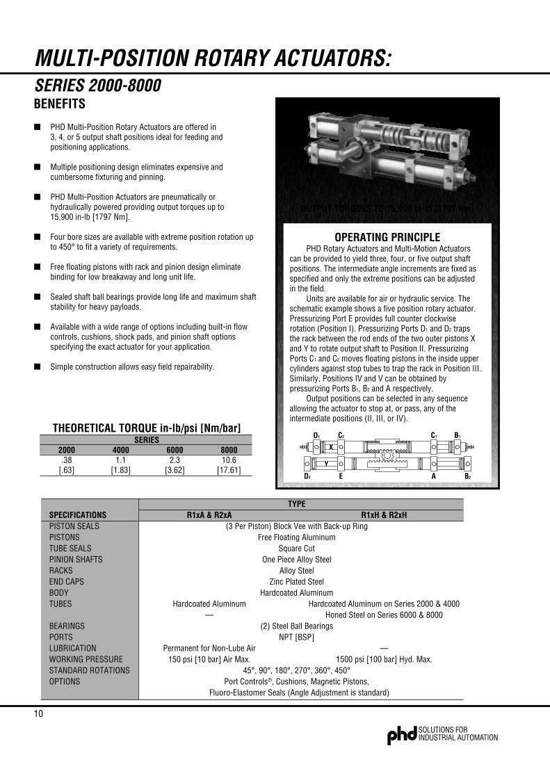
MULTI-POSITION ROTARY ACTUATORS:SERIES 2000-8000
B1C1C2D1
B2AED2
X
Y
OPERATING PRINCIPLEPHD Rotary Actuators and Multi-Motion Actuators
can be provided to yield three, four, or five output shaftpositions. The intermediate angle increments are fixed asspecified and only the extreme positions can be adjustedin the field.
Units are available for air or hydraulic service. Theschematic example shows a five position rotary actuator.Pressurizing Port E provides full counter clockwiserotation (Position I). Pressurizing Ports D1 and D2 trapsthe rack between the rod ends of the two outer pistons Xand Y to rotate output shaft to Position II. PressurizingPorts C1 and C2 moves floating pistons in the inside uppercylinders against stop tubes to trap the rack in Position III.Similarly, Positions IV and V can be obtained bypressurizing Ports B1, B2 and A respectively.
Output positions can be selected in any sequenceallowing the actuator to stop at, or pass, any of theintermediate positions (II, III, or IV).
OUTPUT TORQUES TO 15,900 in-lb [1797 Nm]
THEORETICAL TORQUE in-lb/psi [Nm/bar]SERIES
2000 4000 6000 8000.38 1.1 2.3 10.6
[.63] [1.83] [3.62] [17.61]
BENEFITS
■ PHD Multi-Position Rotary Actuators are offered in3, 4, or 5 output shaft positions ideal for feeding andpositioning applications.
■ Multiple positioning design eliminates expensive andcumbersome fixturing and pinning.
■ PHD Multi-Position Actuators are pneumatically orhydraulically powered providing output torques up to15,900 in-lb [1797 Nm].
■ Four bore sizes are available with extreme position rotation upto 450° to fit a variety of requirements.
■ Free floating pistons with rack and pinion design eliminatebinding for low breakaway and long unit life.
■ Sealed shaft ball bearings provide long life and maximum shaftstability for heavy payloads.
■ Available with a wide range of options including built-in flowcontrols, cushions, shock pads, and pinion shaft optionsspecifying the exact actuator for your application.
■ Simple construction allows easy field repairability.
TYPESPECIFICATIONS R1xA & R2xA R1xH & R2xHPISTON SEALS (3 Per Piston) Block Vee with Back-up RingPISTONS Free Floating AluminumTUBE SEALS Square CutPINION SHAFTS One Piece Alloy SteelRACKS Alloy SteelEND CAPS Zinc Plated SteelBODY Hardcoated AluminumTUBES Hardcoated Aluminum Hardcoated Aluminum on Series 2000 & 4000
— Honed Steel on Series 6000 & 8000BEARINGS (2) Steel Ball BearingsPORTS NPT [BSP]LUBRICATION Permanent for Non-Lube Air —WORKING PRESSURE 150 psi [10 bar] Air Max. 1500 psi [100 bar] Hyd. Max.STANDARD ROTATIONS 45°, 90°, 180°, 270°, 360°, 450°OPTIONS Port Controls®, Cushions, Magnetic Pistons,
Fluoro-Elastomer Seals (Angle Adjustment is standard)

11
ZA MAX
F
H
ZA MAX
NB +.025-.000 DIAG
Y + (T° x Z)A + (T° x B)
M THREAD4X EACH FRONT,BACK & BOTTOM
ED
4XX BSP
C/2
C
L
JA
KA SQ
SPECIFIED BY 3R2xxWHEN ORDERING
S TA
Q
OU
PA
W KEYWAY
V DIA
R
SHAFT KEYWAY: SHOWN AT MID-ROTATIONPORT POSITIONS: INDICATED BY CIRCLED NUMBERSCUSHIONS: SERIES 2000 ACTUATORS:
ADD 13.0 mm TO RESPECTIVE “A” AND “Y” DIMENSION FOR EACH CUSHIONMTG. HOLES: CENTERED ON CENTERLINE OF ACTUATOR BODYSTOP TUBES: LOCATED IN TUBES I & IIPLUMBING SCHEMATIC: L0CATED IN ENGINEERING DATA SECTION
I II
III IV
QUICK REFERENCE FOR: A + (T° x B)
LETTER DIMENSION
A145201292302
B0.440.660.661.32
C76108127203
D5176102127
E38.150.863.576.2
F691012
G13171927
H06511
JA19292948
KA35485789
L36535892
O50.876.276.2
127.0
PA22484889
Q50.876.288.9
127.0
R13161938
S6
131332
TA38.150.850.863.5
U8
141019
XG1/8G1/4G1/4G3/8
Y72100116154
Z0.220.330.330.66
ZA29384873
MM6 x 1.0 x 8
M8 x 1.0 x 13M10 x 1.5 x 16M20 x 2.5 x 32
45164.6230.5261.5368.3
90184.5260.2291.1427.7
180224.2319.8410.8539.6
270264.1379.1350.7546.6
360303.8438.6469.5784.4
450343.6498.0529.0903.2
NB28.58 x 1.4 DP50.80 x 1.0 DP55.00 x 1.3 DP85.00 x 3.0 DP
V12.69/12.7122.22/22.2328.55/28.5844.42/44.45
W3.15 x 1.59 x 164.75 x 2.36 x 386.35 x 3.18 x 389.53 x 2.36 x 78
V12.00/11.9722.00/21.9628.00/27.9644.00/43.96
W4 x 2.5 x 156 x 3.5 x 328 x 5 x 40
12 x 5 x 56
C1
A
C2
E
ACTUATORTYPE
3R1xA & 3R2xA3R1xH & 3R2xH
IIII
PORTS PRESSURIZEDC1 & C2
II
LETTER OPTIONREFERENCED BY TUBE NUMBER
PORT & NEEDLE LOCATIONSREFERENCED BY CIRCLED NUMBERS
OPTION LOCATION REFERENCE
PORT PRESSURIZED - EFULL CCW POSITION
PORT PRESSURIZED - AFULL CW POSITION
-DI & III & II
DEGREE OF ROTATION
SERIES2000400060008000
SERIES2000400060008000
1
2
2
3
4
4
T°
R°I°
PORT44
-P1 & 31 & 3
-D11
-TPORT
22
-P1 & 31 & 3
-D11
STANDARD-MALLALL
-PALLALL
-ASTANDARDSTANDARD
-BI & IIN/A
-EALLALL
IMPERIAL SHAFTS* METRIC SHAFTS*
* BOTH IMPERIAL AND METRIC SHAFT OPTIONS AVAILABLE ON METRIC BODY (IMPERIAL SHAFT = DESIGN 5, AND METRIC SHAFT = DESIGN 6). NUMBERS FOR METRIC UNITS AND ARE IN mm.
METRIC
DIMENSIONS: 3 POSITION ROTARY ACTUATORS
All dimensions are reference only unless specifically toleranced.

12 METRIC
DIMENSIONS: 4 POSITION ROTARY ACTUATORS
ZA MAX
F
H NB +.025-.000DIAG YB + (T° x Z)
Y + (T° x Z)
M THREAD4X EACH FRONT,BACK & BOTTOM
ED
6X X BSP
C/2
C
L
JA
KA SQSPECIFIED BY 4R2xxWHEN ORDERING
S TA
Q
OU
PA
W KEYWAY
V DIA
R
FA
GA
YA + Z (T° + J°)
F
HG
YA + Z (T° + K°)
V
VI
SHAFT KEYWAY: SHOWN AT MID-ROTATIONPORT POSITIONS: INDICATED BY CIRCLED NUMBERSMTG. HOLES: CENTERED ON CENTERLINE OF ACTUATOR BODYSTOP TUBES: LOCATED IN TUBES I & IIPLUMBING SCHEMATIC: L0CATED IN ENGINEERING DATA SECTION
I II
III IV
LETTER DIMENSION
C108127203
D76102127
E50.863.576.2
F91012
G171927
H6511
JA292948
KA485789
L535892
O76.276.2127.0
PA484889
Q76.288.9
127.0
R161938
S131332
TA50.850.863.5
XG1/4G1/4G3/8
Y102118126
Z0.330.330.66
ZA384873
MM8 x 1.25 x 13M10 x 1.5 x 16M20 x 2.5 x 32
FA10912
GA181827
U141019
YA171186251
YB85101133
NB50.80 x 1.0 DP55.00 x 1.3 DP85.00 x 3.0 DP
V22.22/22.2328.55/28.5844.42/44.45
W4.75 x 2.36 x 386.35 x 3.18 x 389.53 x 2.36 x 78
V22.00/21.9628.00/27.9644.00/43.96
W6 x 3.5 x 328 x 5 x 40
12 x 5 x 56
-D1 & 31 & 3
ACTUATORTYPE
4R1xA & 4R2xA4R15xH & 4R2xH
LETTER OPTIONREFERENCED BY TUBE NUMBER
PORT & NEEDLE LOCATIONSREFERENCED BY CIRCLED NUMBERS
OPTION LOCATION REFERENCE
-DII & IVII & IV
C1
A
C2
E
D1
D2
IV
IIIII
I
PORTS PRESSURIZEDC1 & C2
PORTS PRESSURIZED – AFULL CW POSITION
PORTS PRESSURIZEDD1 & D2
PORTS PRESSURIZED – EFULL CCW POSITION
PORT44
-P1 & 31 & 3
-D1 & 31 & 3
-TPORT
22
-P1 & 31 & 3
STANDARD
SERIES400060008000
-MALLALL
-PALLALL
-ASTANDARDSTANDARD
-BII & IV
N/A
-EALLALL
1
2
2
3
4
4
T°
K°
I°R°J°
IMPERIAL SHAFTS* METRIC SHAFTS*
* BOTH IMPERIAL AND METRIC SHAFT OPTIONS AVAILABLE ON METRIC BODY (IMPERIAL SHAFT = DESIGN 5, AND METRIC SHAFT = DESIGN 6). NUMBERS FOR METRIC UNITS AND ARE IN mm.
All dimensions are reference only unless specifically toleranced.
13
METRIC
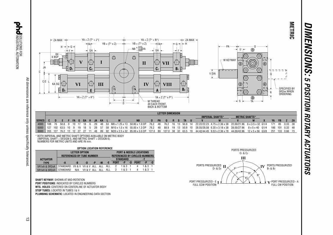
DIMENSIONS: 5 POSITION ROTARY ACTUATORS
SPECIFIED BY5R2xx WHENORDERING
S TA
Q
OU
PA
W KEYWAY
V DIA
R
ZA MAX
FH
NB +.025-.000DIA
GYB + (T° x Z)
M THREAD4X EACH FRONT,BACK & BOTTOM
ED
8XX BSP
C/2
C
L
JA
KA SQ
FA
GA
YA + Z (T° + J°)
F
HG
YA + Z (T° + K°)
V
VI
ZA MAXYB + (T° x Z)
YA + Z (T° + N°)
B2
B1
YA + Z (T° x P°)
GA
FA
SHAFT KEYWAY: SHOWN AT MID-ROTATIONPORT POSITIONS: INDICATED BY CIRCLED NUMBERSMTG. HOLES: CENTERED ON CENTERLINE OF ACTUATOR BODYSTOP TUBES: LOCATED IN TUBES I & IIPLUMBING SCHEMATIC: L0CATED IN ENGINEERING DATA SECTION
I II
III IV VIII
VII
LETTER DIMENSION
C108127203
D76102127
E50.863.576.2
F91012
G171927
H6511
JA292948
KA485789
L535892
O76.276.2
127.0
PA484889
Q76.288.9
127.0
R161938
S131332
TA50.850.863.5
U141019
XG1/4G1/4G3/8
Z0.330.330.66
ZA384873
MM8 x 1.25 x 13M10 x 1.5 x 16M20 x 2.5 x 32
FA109
12
GA181827
YA171186251
YB85101133
V22.22/22.2328.55/28.5844.42/44.45
W4.75 x 2.36 x 386.35 x 3.18 x 389.53 x 2.36 x 78
V22.00/21.9628.00/27.9644.00/43.96
W6 x 3.5 x 328 x 5 x 4012 x 5 x 56
1
2
2
3
4
4
PORT44
-P1 & 31 & 3
-D11
-TPORT
22
-P1 & 31 & 3
-D11
STANDARD-MALLALL
-PALLALL
-ASTANDARDSTANDARD
-EALLALL
C1
A
C2
E
D1
D2
ACTUATORTYPE
5R1xA & 5R2xA5R1xH & 5R2xH
LETTER OPTIONREFERENCED BY TUBE NUMBER
PORT & NEEDLE LOCATIONSREFERENCED BY CIRCLED NUMBERS
OPTION LOCATION REFERENCE
-DVII & VVII & V
IV
III
II
I VPORT PRESSURIZED - EFULL CCW POSITION
PORTS PRESSURIZEDD1 & D2
PORT PRESSURIZED - AFULL CW POSITION
PORTS PRESSURIZEDB1 & B2
PORTS PRESSURIZEDC1 & C2
T°
P°
I°
J°K°
N°R°
-BVII & V
N/A
SERIES400060008000
NB50.80 x 1.0 DP55.00 x 1.3 DP85.00 x 3.0 DP
IMPERIAL SHAFTS* METRIC SHAFTS*
* BOTH IMPERIAL AND METRIC SHAFT OPTIONS AVAILABLE ON METRIC BODY (IMPERIAL SHAFT = DESIGN 5, AND METRIC SHAFT = DESIGN 6). NUMBERS FOR METRIC UNITS AND ARE IN mm.
All dimensions are reference only unless specifically toleranced.

14
RATINGSAll pneumatic rotary actuators have a maximum pressure rating of
150 psi [10 bar] air. Most hydraulic rotary actuators have a maximumpressure rating of 1500 psi [100 bar]. Except as noted in chart below.*
Minimum factor of safety at maximum rated hydraulic pressure foroutput shaft is 2:1, and for hydraulic chambers is 3:1. Consult PHD forproof pressure data.
BREAKAWAYAll RxxA, RxxH units will breakway at 20 psi [1.4 bar]. All tandem
RxxR units will breakaway at 40 psi [2.8 bar]. 018x air units willbreakaway at 20 psi [1.4 bar], 018x tandem units will breakaway at 30psi [2.1 bar].
TEMPERATURE LIMITS AND FLUIDSRotary Actuator units are equipped with Buna-N piston seals
suitable for use in temperatures ranging from -20° to +180°F[-28° to 82°C] and may be used with air, water, petroleum-basedhydraulic fluid, or fuel oil.
Seals for other fluids or temperature requirements are available, butmust be specified. All Rotary Actuators have teflon back-up rings foruniversal use (except Miniature Rotary Actuators Series 018x).
NOTE: For applications where water-based fluids are used, the unitsmust be modified. Consult PHD for specifications.
LUBRICATIONGear racks and pinion are lubricated at the factory and may never
need lubrication. However, if lubrication should be needed due to adverseconditions, use high grade bearing grease.
NOTE: Port for grease nipple provided in top of actuator body.Lubricate only while ports are pressurized except on 018x75 and 018x50,which have no lube ports.
Approximately 1/2 in3 [8 cm3] of grease is sufficient for any seriesactuator, each 250,000 cycles of 360° duration.
HYD OPTION psi [bar]SERIES *PLAIN -P -D -E OR -M
1000 — — — — — — — —2000 1000 [69] 750 [52] 750 [52] — —3000 — — — — — — — —4000 — — 750 [52] 750 [52] — —5000 — — — — — — 1100 [76]6000 — — 750 [52] 750 [52] 1100 [76]7000 — — — — — — 500 [35]8000 — — 750 [52] 750 [52] 500 [35]
ENGINEERING DATA: SERIES 1000-8000 ROTARY ACTUATORSCONTROLS
Rotary Actuator units are operated by directional valves in the samemanner as air and hydraulic cylinders.
Control of piston speeds is extremely important as inertia force is afunction of rotational speed and distance from load to output shaft center.
ANGLE OF ROTATIONSeries 1000-8000 Rotary Actuators are furnished in 6 stock angles:
45°, 90°, 180°, 270°, 360°, and 450°. Other angles are available asspecified.
Series 018x Miniature Rotary Actuators are all furnished with 180°rotation, but can be adjusted anywhere from 180° to 0°.
TOTAL ROTATIONALTOLERANCES & BACKLASH
**Rotational position from one intermediate position to another(measured at centers of backlash).
NOTE: 3 position and 5 position have 0° backlash at ends of rotation.4 position will have up to stated figure at ends of rotation.
MULTI-POSITION MID-POSITIONTOLERANCES & BACKLASH
Double rack actuators are available with 0° backlash at ends ofrotation, if -A option is used.
Total rotational tolerance may be on both or either sides of mid-rotation minimum.
SERIES ROTATIONAL TOLERANCE BACKLASH1000 & 2000 -0°, +10° *±30 minutes3000 & 4000 -0°, +10° *±15 minutes5000 & 6000 -0°, +10° *±15 minutes7000 & 8000 -0°, +10° *±7.5 minutes
018x75x -0°, +10° ±1.25 minutes duringrotation, ±0° at end
018x50x -0°, +10° ±2 minutes duringrotation, ±0° at end
SERIES TOLERANCE** BACKLASH2000 ±1° ± 1-1/2°
4000 & 6000 ±1/2° ± 1-1/4°8000 ±1/4° ± 1°
018x752 (3 pos.) Adjustable Adjustable to 0°
15
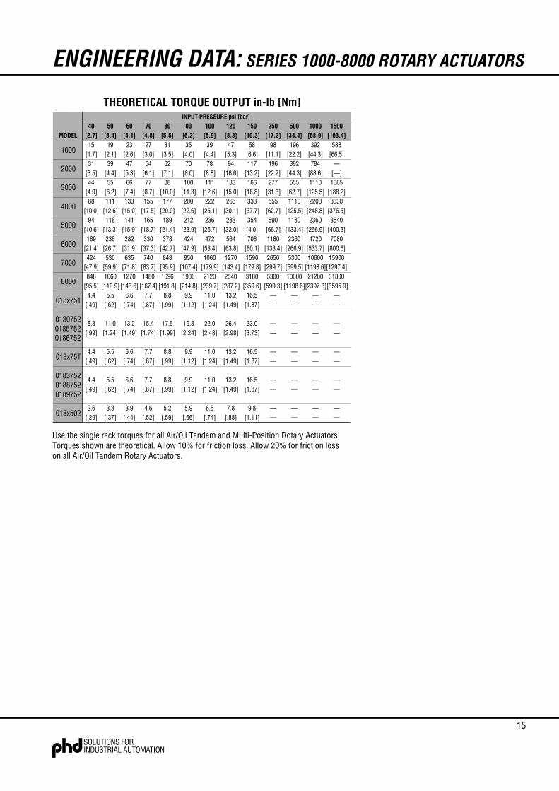
INPUT PRESSURE psi [bar]40 50 60 70 80 90 100 120 150 250 500 1000 1500
MODEL [2.7] [3.4] [4.1] [4.8] [5.5] [6.2] [6.9] [8.3] [10.3] [17.2] [34.4] [68.9] [103.4]15 19 23 27 31 35 39 47 58 98 196 392 588
[1.7] [2.1] [2.6] [3.0] [3.5] [4.0] [4.4] [5.3] [6.6] [11.1] [22.2] [44.3] [66.5]31 39 47 54 62 70 78 94 117 196 392 784 —
[3.5] [4.4] [5.3] [6.1] [7.1] [8.0] [8.8] [16.6] [13.2] [22.2] [44.3] [88.6] [—]44 55 66 77 88 100 111 133 166 277 555 1110 1665
[4.9] [6.2] [7.4] [8.7] [10.0] [11.3] [12.6] [15.0] [18.8] [31.3] [62.7] [125.5] [188.2]88 111 133 155 177 200 222 266 333 555 1110 2200 3330
[10.0] [12.6] [15.0] [17.5] [20.0] [22.6] [25.1] [30.1] [37.7] [62.7] [125.5] [248.8] [376.5]94 118 141 165 189 212 236 283 354 590 1180 2360 3540
[10.6] [13.3] [15.9] [18.7] [21.4] [23.9] [26.7] [32.0] [4.0] [66.7] [133.4] [266.9] [400.3]189 236 282 330 378 424 472 564 708 1180 2360 4720 7080
[21.4] [26.7] [31.9] [37.3] [42.7] [47.9] [53.4] [63.8] [80.1] [133.4] [266.9] [533.7] [800.6]424 530 635 740 848 950 1060 1270 1590 2650 5300 10600 15900
[47.9] [59.9] [71.8] [83.7] [95.9] [107.4] [179.9] [143.4] [179.8] [299.7] [599.5] [1198.6][1297.4]848 1060 1270 1480 1696 1900 2120 2540 3180 5300 10600 21200 31800
[95.5] [119.9] [143.6] [167.4] [191.8] [214.8] [239.7] [287.2] [359.6] [599.3] [1198.6][2397.3][3595.9]4.4 5.5 6.6 7.7 8.8 9.9 11.0 13.2 16.5 — — — —
[.49] [.62] [.74] [.87] [.99] [1.12] [1.24] [1.49] [1.87] — — — —
8.8 11.0 13.2 15.4 17.6 19.8 22.0 26.4 33.0 — — — —[.99] [1.24] [1.49] [1.74] [1.99] [2.24] [2.48] [2.98] [3.73] — — — —
4.4 5.5 6.6 7.7 8.8 9.9 11.0 13.2 16.5 — — — —[.49] [.62] [.74] [.87] [.99] [1.12] [1.24] [1.49] [1.87] — — — —
4.4 5.5 6.6 7.7 8.8 9.9 11.0 13.2 16.5 — — — —[.49] [.62] [.74] [.87] [.99] [1.12] [1.24] [1.49] [1.87] — — — —
2.6 3.3 3.9 4.6 5.2 5.9 6.5 7.8 9.8 — — — —[.29] [.37] [.44] [.52] [.59] [.66] [.74] [.88] [1.11] — — — —
1000
2000
3000
4000
5000
6000
7000
8000
018x751
018075201857520186752
018x75T
018375201887520189752
018x502
ENGINEERING DATA: SERIES 1000-8000 ROTARY ACTUATORS
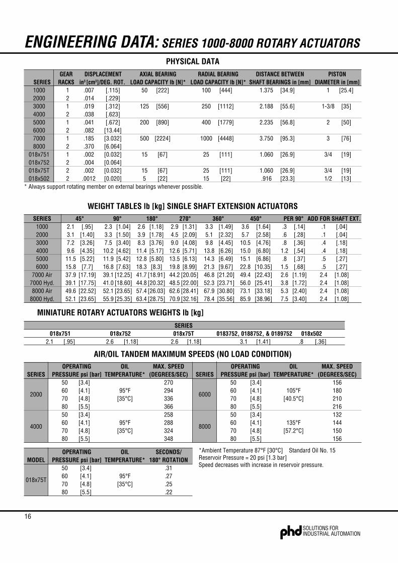
Use the single rack torques for all Air/Oil Tandem and Multi-Position Rotary Actuators.Torques shown are theoretical. Allow 10% for friction loss. Allow 20% for friction losson all Air/Oil Tandem Rotary Actuators.
THEORETICAL TORQUE OUTPUT in-lb [Nm]
16
ENGINEERING DATA: SERIES 1000-8000 ROTARY ACTUATORS
SERIES 45° 90° 180° 270° 360° 450° PER 90° ADD FOR SHAFT EXT.1000 2.1 [.95] 2.3 [1.04] 2.6 [1.18] 2.9 [1.31] 3.3 [1.49] 3.6 [1.64] .3 [.14] .1 [.04]2000 3.1 [1.40] 3.3 [1.50] 3.9 [1.78] 4.5 [2.09] 5.1 [2.32] 5.7 [2.58] .6 [.28] .1 [.04]3000 7.2 [3.26] 7.5 [3.40] 8.3 [3.76] 9.0 [4.08] 9.8 [4.45] 10.5 [4.76] .8 [.36] .4 [.18]4000 9.6 [4.35] 10.2 [4.62] 11.4 [5.17] 12.6 [5.71] 13.8 [6.26] 15.0 [6.80] 1.2 [.54] .4 [.18]5000 11.5 [5.22] 11.9 [5.42] 12.8 [5.80] 13.5 [6.13] 14.3 [6.49] 15.1 [6.86] .8 [.37] .5 [.27]6000 15.8 [7.7] 16.8 [7.63] 18.3 [8.3] 19.8 [8.99] 21.3 [9.67] 22.8 [10.35] 1.5 [.68] .5 [.27]
7000 Air 37.9 [17.19] 39.1 [12.25] 41.7 [18.91] 44.2 [20.05] 46.8 [21.20] 49.4 [22.43] 2.6 [1.19] 2.4 [1.08]7000 Hyd. 39.1 [17.75] 41.0 [18.60] 44.8 [20.32] 48.5 [22.00] 52.3 [23.71] 56.0 [25.41] 3.8 [1.72] 2.4 [1.08]8000 Air 49.6 [22.52] 52.1 [23.65] 57.4 [26.03] 62.6 [28.41] 67.9 [30.80] 73.1 [33.18] 5.3 [2.40] 2.4 [1.08]
8000 Hyd. 52.1 [23.65] 55.9 [25.35] 63.4 [28.75] 70.9 [32.16] 78.4 [35.56] 85.9 [38.96] 7.5 [3.40] 2.4 [1.08]
*Ambient Temperature 87°F [30°C] Standard Oil No. 15Reservoir Pressure = 20 psi [1.3 bar]Speed decreases with increase in reservoir pressure.
AIR/OIL TANDEM MAXIMUM SPEEDS (NO LOAD CONDITION)
MINIATURE ROTARY ACTUATORS WEIGHTS lb [kg]
WEIGHT TABLES lb [kg] SINGLE SHAFT EXTENSION ACTUATORS
PHYSICAL DATA
SERIES018x751 018x752 018x75T 0183752, 0188752, & 0189752 018x502
2.1 [.95] 2.6 [1.18] 2.6 [1.18] 3.1 [1.41] .8 [.36]
OPERATING OIL MAX. SPEED OPERATING OIL MAX. SPEEDSERIES PRESSURE psi [bar] TEMPERATURE* (DEGREES/SEC) SERIES PRESSURE psi [bar] TEMPERATURE* (DEGREES/SEC)
50 [3.4] 270 50 [3.4] 156
200060 [4.1] 95°F 294
600060 [4.1] 105°F 180
70 [4.8] [35°C] 336 70 [4.8] [40.5°C] 21080 [5.5] 366 80 [5.5] 21650 [3.4] 258 50 [3.4] 132
400060 [4.1] 95°F 288
800060 [4.1] 135°F 144
70 [4.8] [35°C] 324 70 [4.8] [57.2°C] 15080 [5.5] 348 80 [5.5] 156
OPERATING OIL SECONDS/MODEL PRESSURE psi [bar] TEMPERATURE* 180° ROTATION
50 [3.4] .31
018x75T60 [4.1] 95°F .2770 [4.8] [35°C] .2580 [5.5] .22
GEAR DISPLACEMENT AXIAL BEARING RADIAL BEARING DISTANCE BETWEEN PISTONSERIES RACKS in3 [cm3]/DEG. ROT. LOAD CAPACITY lb [N]* LOAD CAPACITY lb [N]* SHAFT BEARINGS in [mm] DIAMETER in [mm]1000 1 .007 [.115] 50 [222] 100 [444] 1.375 [34.9] 1 [25.4]2000 2 .014 [.229]3000 1 .019 [.312] 125 [556] 250 [1112] 2.188 [55.6] 1-3/8 [35]4000 2 .038 [.623]5000 1 .041 [.672] 200 [890] 400 [1779] 2.235 [56.8] 2 [50]6000 2 .082 [13.44]7000 1 .185 [3.032] 500 [2224] 1000 [4448] 3.750 [95.3] 3 [76]8000 2 .370 [6.064]
018x751 1 .002 [0.032] 15 [67] 25 [111] 1.060 [26.9] 3/4 [19]018x752 2 .004 [0.064]018x75T 2 .002 [0.032] 15 [67] 25 [111] 1.060 [26.9] 3/4 [19]018x502 2 .0012 [0.020] 5 [22] 15 [22] .916 [23.3] 1/2 [13]
* Always support rotating member on external bearings whenever possible.

17
PLUMBING SCHEMATICS: ROTARY ACTUATORS
C2
E
C1
A
S2 S1 S3
I
T°
I° R°
II
III
PORTS PRESSURIZEDC1 & C2
PORT PRESSURIZED - EFULL CCW POSITION
PORT PRESSURIZED - AFULL CW POSITION
I
T°
J° K°
II
III
PORTS PRESSURIZEDD1 & D2
PORT PRESSURIZED - EFULL CCW POSITION
PORT PRESSURIZED - C2FULL CW POSITION
D1
D2
S2 S1 S3
E
C2
3 POSITION UNITSSERIES 2000-8000
3 POSITION TANDEM UNITSSERIES 2000-8000
18
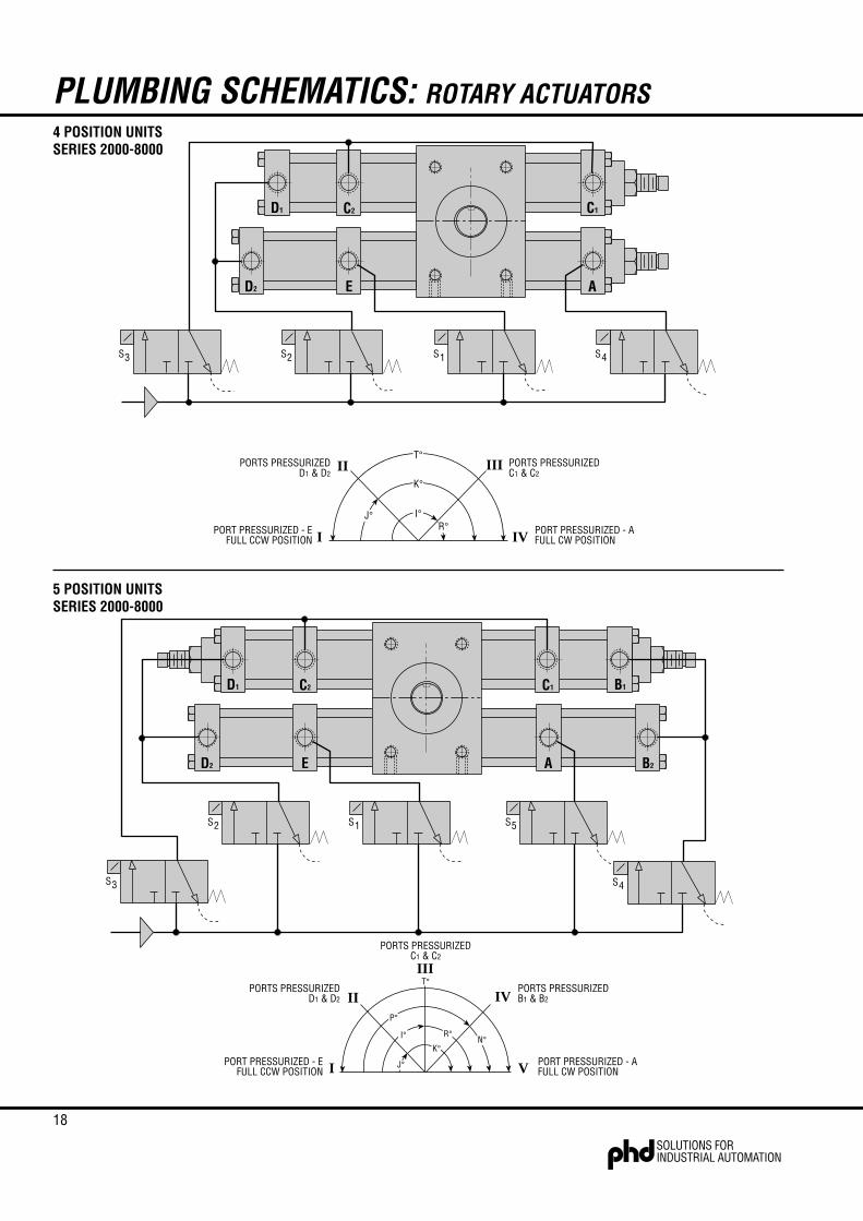
PLUMBING SCHEMATICS: ROTARY ACTUATORS
I
II III
PORT PRESSURIZED - EFULL CCW POSITION
PORT PRESSURIZED - AFULL CW POSITION
J° I°R°
K°
IV
T°PORTS PRESSURIZED
D1 & D2PORTS PRESSURIZEDC1 & C2
A
S3 S2 S1
E
C2
S4
C1D1
D2
T°III
PORTS PRESSURIZEDC1 & C2
A
S3
S2 S1
E
C2
S5
B1D1
D2
S4
C1
B2
I
II IV
PORT PRESSURIZED - EFULL CCW POSITION
PORT PRESSURIZED - AFULL CW POSITIONV
PORTS PRESSURIZEDD1 & D2
PORTS PRESSURIZEDB1 & B2
I°
J°
R°
K°
P°
N°
4 POSITION UNITSSERIES 2000-8000
5 POSITION UNITSSERIES 2000-8000
19
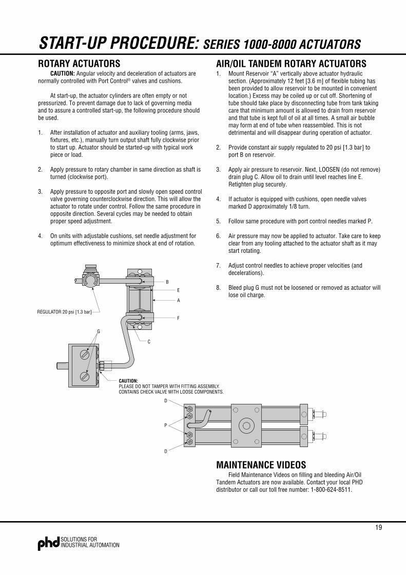
START-UP PROCEDURE: SERIES 1000-8000 ACTUATORSROTARY ACTUATORS
CAUTION: Angular velocity and deceleration of actuators arenormally controlled with Port Control® valves and cushions.
At start-up, the actuator cylinders are often empty or notpressurized. To prevent damage due to lack of governing mediaand to assure a controlled start-up, the following procedure shouldbe used.
1. After installation of actuator and auxiliary tooling (arms, jaws,fixtures, etc.), manually turn output shaft fully clockwise priorto start up. Actuator should be started-up with typical workpiece or load.
2. Apply pressure to rotary chamber in same direction as shaft isturned (clockwise port).
3. Apply pressure to opposite port and slowly open speed controlvalve governing counterclockwise direction. This will allow theactuator to rotate under control. Follow the same procedure inopposite direction. Several cycles may be needed to obtainproper speed adjustment.
4. On units with adjustable cushions, set needle adjustment foroptimum effectiveness to minimize shock at end of rotation.
AIR/OIL TANDEM ROTARY ACTUATORS1. Mount Reservoir “A” vertically above actuator hydraulic
section. (Approximately 12 feet [3.6 m] of flexible tubing hasbeen provided to allow reservoir to be mounted in convenientlocation.) Excess may be coiled up or cut off. Shortening oftube should take place by disconnecting tube from tank takingcare that minimum amount is allowed to drain from reservoirand that tube is kept full of oil at all times. A small air bubblemay form at end of tube when reassembled. This is notdetrimental and will disappear during operation of actuator.
2. Provide constant air supply regulated to 20 psi [1.3 bar] toport B on reservoir.
3. Apply air pressure to reservoir. Next, LOOSEN (do not remove)drain plug C. Allow oil to drain until level reaches line E.Retighten plug securely.
4. If actuator is equipped with cushions, open needle valvesmarked D approximately 1/8 turn.
5. Follow same procedure with port control needles marked P.
6. Air pressure may now be applied to actuator. Take care to keepclear from any tooling attached to the actuator shaft as it maystart rotating.
7. Adjust control needles to achieve proper velocities (anddecelerations).
8. Bleed plug G must not be loosened or removed as actuator willlose oil charge.
REGULATOR 20 psi [1.3 bar]
B
E
A
F
C
G
CAUTION:PLEASE DO NOT TAMPER WITH FITTING ASSEMBLY.CONTAINS CHECK VALVE WITH LOOSE COMPONENTS.
D
D
P
MAINTENANCE VIDEOSField Maintenance Videos on filling and bleeding Air/Oil
Tandem Actuators are now available. Contact your local PHDdistributor or call our toll free number: 1-800-624-8511.

20
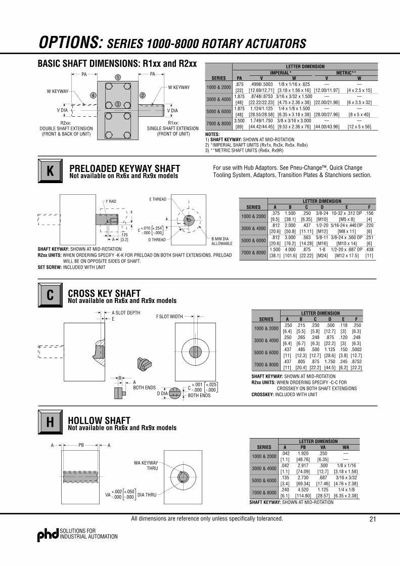
OPTIONS: SERIES 1000-8000 ROTARY ACTUATORS
P PORT CONTROL®
The “built-in” speed control valve.The exclusive PHD Port Control®, based on the “meter-out”
principle, features an adjustable needle and a separate ball check.Both are built into the rotary actuator end cap and are used tocontrol the speed of the actuator over its entire rotation.
D ADJUSTABLE CUSHIONS
PHD Cushions are designed for smooth deceleration at the endof rotation. When the cushion is activated, the remaining volume inthe cylinder must exhaust past an adjustable needle which controlsthe amount of deceleration. Effective cushion length isapproximately 30° of rotation, except on the 8000 Tandem whichhas 20° of cushion length.
Cushions on Series 2000, 4000, 6000 and 8000 are furnishedon one of two racks only.
Fits all PHD Series 1000-8000, except when ordering hollowshafts. Isolates internal or external pressures. Maximum pressuredifferential is 500 psi [34.4 bar]. Furnished installed on actuator only(both sides). Covers are made of hard anodized aluminum. Not to beused as a pilot.
G SHAFT SEAL COVERSNot available on Rx6x and Rx9x models
SHOCK PADS
Polyurethane pads for absorption of shock and noise areavailable on each end of Series 1000-8000 Rotary Actuators.Reducing shock permits higher piston velocities for shorter cycletimes. Reducing noise levels provides improved environment forincreased productivity. Pads eliminate metal-to-metal contactbetween piston and end caps. NOTE: Air application only.
B
Adjusting screw(s) for reducing angle of rotation in either orboth directions for use where exact degree of desired rotationcannot be predetermined or where requirements may vary duringoperation. Standard adjusting screw will reduce angle of rotation upto 30°. Available in conjunction with all other optional features.
Cushions are normally engaged over the last 30° of angle. Theuse of angle adjusting screws to reduce angle of rotation has adirect effect on the length of cushion engagement. Example: 10°angle reduction will reduce cushion engagement by 10°. Angleadjustments are standard on all Multi-Position Rotary Actuators.
A ANGLE ADJUSTMENTZA MAX
ZD DIA
HZB
ZC
H0.00[0]
.250[6]
.203[5]
.437[11]
ZA1.125[29]
1.500[38]
1.875[48]
2.875[73]
ZB.312[8]
.375[10].750[19].937[24]
ZC3/16 HEX
—1/4 HEX
— 1/4 HEX
—3/4 FLAT[19 mm]
ZD.875[22]
1.250[32]
1.250[32]
1.750[45]
SERIESLETTER DIMENSION
1000 & 2000
3000 & 4000
5000 & 6000
7000 & 8000
A DIA
.187+.000-.010
B REF
+.000-.254 A
1.875[47.63]3.000
[76.20]3.250
[82.55]4.480
[113.79]
B.688
[17.5]1.688[42.9]1.688[42.9]3.312[84.1]
SERIESLETTER
1000 & 2000
3000 & 4000
5000 & 6000
7000 & 8000
The self-locking needle has micrometer threads and isadjustable under pressure. It determines the orifice size whichcontrols the exhaust volume only of the actuator proper. Theseparate ball check is closed while fluid is exhausting from theactuator, but opens to permit full flow of incoming fluids. The PHDPort Control® provides the optimum in speed control for rotaryactuators. It saves space and eliminates the cost of fittings andinstallation for external flow control valves.
All dimensions are reference only unless specifically toleranced.
NUMBERS IN [ ] ARE FOR METRIC UNITS AND ARE IN mm.
NUMBERS IN [ ] ARE FOR METRICUNITS AND ARE IN mm.
21
OPTIONS: SERIES 1000-8000 ROTARY ACTUATORSBASIC SHAFT DIMENSIONS: R1xx and R2xx
H HOLLOW SHAFTNot available on Rx6x and Rx9x models
C CROSS KEY SHAFTNot available on Rx6x and Rx9x models
K PRELOADED KEYWAY SHAFTNot available on Rx6x and Rx9x models
V WIMPERIAL* METRIC**
V WSERIES
1000 & 2000
3000 & 4000
5000 & 6000
7000 & 8000
LETTER DIMENSION
NOTES:
V DIA
W KEYWAY
PAPA
V DIA
W KEYWAY
DOUBLE SHAFT EXTENSION(FRONT & BACK OF UNIT)
R2xx: R1xx:SINGLE SHAFT EXTENSION
(FRONT OF UNIT)
PA.875[22]
1.875[48]
1.875[48]
3.500[89]
.4998/.5003[12.69/12.71].8748/.8753
[22.22/22.23]1.124/1.125
[28.55/28.58]1.749/1.750
[44.42/44.45]
1/8 x 1/16 x .625[3.18 x 1.56 x 16]
3/16 x 3/32 x 1.500[4.75 x 2.36 x 38]1/4 x 1/8 x 1.500[6.35 x 3.18 x 38]3/8 x 3/16 x 3.000[9.53 x 2.36 x 76]
—[12.00/11.97]
—[22.00/21.96]
—[28.00/27.96]
—[44.00/43.96]
—[4 x 2.5 x 15]
—[6 x 3.5 x 32]
—[8 x 5 x 40]
—[12 x 5 x 56]
1) SHAFT KEYWAY: SHOWN AT MID-ROTATION2) *IMPERIAL SHAFT UNITS (Rx1x, Rx3x, Rx5x. Rx8x)3) **METRIC SHAFT UNITS (Rx6x, Rx9R)
4 2
1
3
A.125[3.2]
F RAD
B MIN DIAALLOWABLE
D THREAD
E THREAD
F
+.010-.000C +.254
-.000
A .375[9.5] .812[20.6] .812[20.6]1.500[38.1]
B1.500[38.1]2.000[50.8]3.000[76.2]4.000
[101.6]
C.250
[6.35].437
[11.11].563
[14.28].875
[22.22]
D3/8-24[M10]1/2-20[M12]5/8-11[M16]
1-8[M24]
E10-32 x .312 DP
[M5 x 8]5/16-24 x .440 DP
[M8 x 11]3/8-24 x .560 DP
[M10 x 14]1/2-20 x .687 DP
[M12 x 17.5]
F.156[4]
.220[6]
.251[6]
.438[11]
SERIES
1000 & 2000
3000 & 4000
5000 & 6000
7000 & 8000
LETTER DIMENSION
SHAFT KEYWAY: SHOWN AT MID-ROTATIONR2xx UNITS: WHEN ORDERING SPECIFY -K-K FOR PRELOAD ON BOTH SHAFT EXTENSIONS. PRELOAD
WILL BE ON OPPOSITE SIDES OF SHAFT.SET SCREW: INCLUDED WITH UNIT
A .250[6.4].250[6.4].437[11].437[11]
B.215[5.5].265[6.7].485
[12.3].805
[20.4]
C.230[5.8].248[6.3].500
[12.7].875
[22.2]
D .500[12.7].875
[22.2]1.125[28.6]1.750[44.5]
E.118[3]
.120[3]
.150[3.8].245[6.2]
F .250[6.3].248[6.3].5002[12.7].8752[22.2]
SERIES
1000 & 2000
3000 & 4000
5000 & 6000
7000 & 8000
LETTER DIMENSION
+.001-.000C
BOTH ENDSD DIA
ABOTH ENDS
B
F SLOT WIDTHA SLOT DEPTHE
SHAFT KEYWAY: SHOWN AT MID-ROTATIONR2xx UNITS: WHEN ORDERING SPECIFY -C-C FOR
CROSSKEY ON BOTH SHAFT EXTENSIONSCROSSKEY: INCLUDED WITH UNIT
+.025-.000
WA KEYWAYTHRU
PB AA
VA DIA THRU+.050-.000
+.002-.000
A .042[1.1].042[1.1].135[3.4].240[6.1]
PB1.920
[48.76]2.917
[74.09]2.730
[69.34]4.520
[114.80]
VA.250
[6.35] .500[12.7].687
[17.46]1.125
[28.57]
WA——
1/8 x 1/16[3.18 x 1.58] 3/16 x 3/32[4.76 x 2.38]
1/4 x 1/8[6.35 x 2.38]
SERIES
1000 & 2000
3000 & 4000
5000 & 6000
7000 & 8000
LETTER DIMENSION
SHAFT KEYWAY: SHOWN AT MID-ROTATION
For use with Hub Adaptors. See Pneu-Change™, Quick ChangeTooling System, Adaptors, Transition Plates & Stanchions section.
All dimensions are reference only unless specifically toleranced.

22
MAGNETIC PISTON FOR USE WITHPHD PROXIMITY SWITCHES
OPTIONS: SERIES 1000-8000 ROTARY ACTUATORS
The PHD Magnetic Reed Switches may be used in situationswhere the Hall Effect Switches are not applicable. As with the HallEffect Switches, a magnetic band (specify -M) on the pistonsactivates the externally mounted PHD Reed Switches. The ReedSwitches may be used to signal a programmable controller,sequencer, relay, or in some cases, a valve solenoid. This option isfor use with the following switches.
Series 1000-8000 Rotary Actuators may be equipped with amagnetic band (specify -E) on the pistons which activates externallymounted PHD Hall Effect Switches. These switches allow theinterfacing of the PHD Actuators to various logic systems. Thisoption is for use with the following switches.
E HALL EFFECT SWITCHES M REED SWITCHES
SET POINT MODULEPART NO. DESCRIPTION
9800-01-0300 NPN (Sink) 4.5-24 VDC9800-01-0400 PNP (Source) 4.5-24 VDC
See Switches and Sensors section for information.
See page 3C-30 for Hydraulic Pressure Ratings with these options.See each ordering data for magnetic piston ordering information.Switches and brackets must be ordered separately.See Switches and Sensors section for complete switch information.
PHD offers a solid state sensor transducer along with aSet Point Module which provides up to four adjustable sensingpositions throughout the 180° maximum sensing range. Thesesignals can be used as inputs to a programmable controller to signalends of rotation in addition to multiple signals during rotation forindication of arc travelled.
The Set Point Module allows independent adjustment of eachsensing position and is available for 4.5 to 24 VDC current sinkingor current sourcing.
To order, specify -J option on Series 1000-8000 and -3 in theappropriate option space.
J SENSOR/SET POINT MODULENot available on Rx6x and Rx9x models
SWITCH BRACKETS
COMPACT HALL EFFECT SWITCHESPART NO. COLOR DESCRIPTION
17503-1-06 Yellow NPN (Sink) Type 4.5-24 VDC, 6 foot cable17504-1-06 Red PNP (Source) Type 4.5-24 VDC, 6 foot cable17523-1 Yellow NPN (Sink) Type 4.5-24 VDC, Quick Connect17524-1 Red PNP (Source) Type 4.5-24 VDC, Quick Connect
LIQUID RESISTANT HALL EFFECT SWITCH PART NO. DESCRIPTION 15902-1 NPN (Sink) or PNP (Source) 4.5-24 VDC
COMPACT REED SWITCHESPART NO. DESCRIPTION
17502-1-06 White NPN (Sink) or PNP (Source) 4.5-24 VDC,6 foot cable
17509-2-06 Green AC Type 110-120 VAC with Current Limit,6 foot cable
17522-1 White NPN (Sink) or PNP (Source) 4.5-24 VDC,Quick Connect
17529-2 Green AC Type 110-120 VAC, Quick Connectwith Current Limit
LIQUID RESISTANT REED SWITCHESPART NO. DESCRIPTION15900-1 10 Watt 4.5-24 VDC or 110-120 VAC15901-1 3 Amp 65-120 VAC
PART NO.SERIES COMPACT SWITCH LIQUID RESISTANT
1000 & 2000 17000-32-0 5142-32-33000 & 4000 17000-34-0 5142-34-35000 & 6000 17000-38-0 5142-38-37000 & 8000 17000-39-0 5142-39-3

23
OPTIONS: SERIES 1000-8000 ROTARY ACTUATORS
LCOUNTERCLOCKWISEUNIDIRECTIONAL CLUTCHNot available on Rx6x and Rx9x models
RCLOCKWISE UNIDIRECTIONALCLUTCHNot available on Rx6x and Rx9x models
Overrun clutch for intermittent unidirectional shaft output,available for Series 1000 through 6000.
Output hub rotates in one direction only. It remains motionlesswhile rack and pinion reverse. Clutch repeats within ±1/2°.
Assembly features a Torrington roller clutch. Spring loadedbrake shoes limit output shaft free wheeling, but are not intended forstopping external loads.
CAUTION: Any angular error will accumulate; therefore, shotpins or similar locators are necessary on index applications.Maintain shot pin location during reversal of Rotary Actuator toguarantee that clutch shaft does not move due to external forces orslight internal friction in clutch.
1.656[42]
ABOVE INLET PRESSURES PROVIDE A MAXIMUM TORQUEOF 414 in-lb [46.8 Nm] ALLOWED BY THE CLUTCH
A .281[7.2].344[8.7].406
[10.3]
C2.938[74.6]4.188
[106.3]4.938
[125.4]
D2.000[51]
3.000[76]
4.000[102]
E1.500[38]
2.000[50.8]2.500[63.5]
Q2.000[50.8]3.000[76.2]3.500[88.9]
MAX. INLETPRESSURE(psi)[bar]
MAX. RADIAL ORAXIAL LOAD (lb) [N]
SERIESLETTER DIMENSION
SERIES100020003000400050006000
LIMITING FACTORS
1000 & 2000
3000 & 4000
5000 & 6000
105252637218617487
5510101515
[72][36][25][13][12][6]
[22][22][44][44][66][66]
Q
ED
C
2X A DIA THRU TOACTUATOR BODY
.500/.502 [12.70/12.75]DIA x .437 [11.1] DP
.873/.875[22.17/22.22] DIA
1.625 [41] DIA
.125/.126[3.17/3.20]THRU DIA
1.250[31.75]
.187 [4.7]
.375 [9.5]
The PVA functions as a built-in pneumatic limit switch. An airpressure signal is provided at the end-of-piston travel as the pistonseal uncovers an orifice in the block. Upon reversal of piston travel,the pilot pressure is shut off and the pilot line is vented through therotary actuator housing.
Air pilot signal is provided approximately .03 inch [1 mm] priorto end of piston travel (or 10 to 15 degrees prior to end of rotation).For pneumatic use only.
PVA ports are located in position 1 unless otherwise specified.Not available in conjunction with angle adjustment -A option.
N PILOT VALVE ACTUATORNot available on Rx6x and Rx9x models
PVA UNITS WILL REQUIRE A MINIMUMROTATION OF 45°
1000 & 2000
3000 & 4000
5000 & 6000
7000 & 8000
PD
.625 [16] SQ.500 [12.7]MAX
PV TYP
2X 1/8 NPT [BSP]
CCW SIGNAL PORTCW SIGNAL PORT
SERIES PD1.000[25.4]1.500[38.1]1.500[38.1]2.500[63.5]
LETTER DIMENSION
W/-B1.848[46.9]2.410[61.2]2.978[75.6]3.770[95.8]
STANDARD2.191[55.7]2.847[72.3]3.436[87.3]4.409[112]
PV
4 2
1
3
All dimensions are reference only unless specifically toleranced.

24
KIT NO.IMPERIAL METRIC
13756 1432013757 1432113758 14322
B2.000 [51]3.000 [76]4.000 [102]
C1.625 [41.3]2.375 [60.3]3.375 [85.7]
D 2.625 [66.7]3.875 [98.4]3.875 [98.4]
E.281 [7.1].406 [10.3].406 [10.3]
F .250 [6.3].437 [11.1].437 [11.1]
A4.250 [108]4.500 [114]4.500 [114]
B2.000 [51]3.000 [76]4.000 [102]5.000 [127]
C1.375 [34.9]2.125 [54.0]3.375 [85.7]3.000 [76.2]
D3.625 [92.1]5.125 [130.2]5.875 [149.2]10.000 [254.0]
E.281 [7.1].406 [10.3].406 [10.3].781 [19.8]
F.250 [6.3].437 [11.1].437 [11.1].750 [19.1]
A4.250 [108]5.750 [146]6.500 [165]12.000 [305]
G .625 [15.9]1.000 [25.4]1.250 [31.8]1.875 [47.6]
KIT NO.IMPERIAL METRIC
13759 1431613760 1431713761 1431813762 14319
LETTER DIMENSION
SERIES1000 & 20003000 & 40005000 & 6000
LETTER DIMENSION
SERIES1000 & 20003000 & 40005000 & 60007000 & 8000
F
AD
4X E DIATHRU
CB
F
AD
4X E DIATHRU
CB
G DIA THRU
OPTIONS: SERIES 1000-8000 ROTARY ACTUATORS
Needles may not be located in same position as ports. Seepage 3C-16 for needle positions Air/Oil Tandem Actuators. See 3C-4for port and Port Control® positions on Miniature Rotary Actuators.
I II
III IV
12
3
4
12
3
4
1
2
3
4
12
3
4
5
I YThis option positions the ports in position 1 on racks I & II and
in position 3 on racks III and IV. This allows access to the ports onthe “Top” and “Bottom” sides of the actuator.
This option rotates the cap of an Air/Oil Tandem RotaryActuator 180°. This places the Port Control (and Cushion) needlesand the Tandem fitting in position 2. Standard position for these isposition 4.
PORT POSITION 1 TOP RACKPORT POSITION 3 BOTTOM RACK TANDEM CAP ROTATED 180°
V FLUORO-ELASTOMER SEALSFluoro-Elastomer seals are available for service up to 400°F
[204°C]. They may also be used to achieve seal compatibility withcertain fluids. Seal compatibility should be checked with the fluidmanufacturer for proper application.
This option may be specified when a precise rotation isrequired and angle adjustment (see page 3C-35) is not acceptable.By specifying this option, rotation will be within a tolerance of+30, -0 minutes. Standard tolerance is -0°, +10° of rotation.
W CLOSE TOLERANCE ROTATION
Z1 ELECTROLESS NICKEL PLATINGElectroless nickel plating is done on all externally exposed
ferrous parts except the pinion shaft. This optional plating treatmentgives an alternative method of protecting the unit from severeenvironments.
NOTE: Standard plating is Zinc & Black Oxide.
MOUNTING FLANGE (HARDWARE INCLUDED)
SIDE MOUNTING FLANGE
BOTTOM MOUNTING FLANGE
PORT & PORT CONTROL LOCATIONSSTANDARD PORT LOCATION on all Series 1000-8000
Actuators is position 2. STANDARD PVA (-N) LOCATIONS aretubes I & II in position 1. STANDARD PORT CONTROL® ANDCUSHION ADJUSTMENT NEEDLES are located in end caps I & IIin position 1. Other port and adjusting needle locations areavailable as specified.
1M-A4 4/01 5307
PHD, Inc. PHD Ltd. PHD GmbH9009 Clubridge Drive 7 Eden Way, Pages Industrial Park Arnold-Sommerfeld-Ring 2
P.O. Box 9070, Fort Wayne, Indiana 46899 U.S.A. Leighton Buzzard, Bedfordshire LU7 8TP U.K. D-52499 Baesweiler GERMANYPhone (219) 747-6151 • Fax (219) 747-6754 Phone 01525 853488 • Fax 01525 378210 Phone 02401-805 230 • Fax 02401-805 232
www.phdinc.com • [email protected]