ron h. geurts, barak d. green, and james e. shigley (diamond e ˝˚˛
TRANSCRIPT
Modeling the Appearance of the Round Brilliant Cut Diamond: An Analysis of Fire, and More About BrillianceIlene M. Reinitz, Mary L. Johnson, T. Scott Hemphill, Al M. Gilbertson,Ron H. Geurts, Barak D. Green, and James E. Shigley
pg. 239
EDITORIAL
REGULAR FEATURES
pg. 207
174
FEATURE ARTICLE
173William E. BoyajianShedding Light on “Fire”
198
206
A report on the unusual pale purple to purplish pink garnets from theWestern Alps of Italy.
Alessandro Guastoni, Federico Pezzotta, Margherita Superchi, and Francesco Demartin
A detailed examination of this rare gemstone, using both standard andadvanced testing methods.
Kenneth Scarratt, Donna Beaton, and Garry DuToit
Pyrope from the Dora Maira Massif, Italy
Jeremejevite: A Gemological Update
212•Gem baddeleyite •Conch “pearls” •13 ct datolite •Carved “Hamsa” dia-mond •Heat-treated black diamonds •Update on blue and pink HPHT-annealed diamonds •Fracture-filled “bloodshot” iolite •Maw-sit-sit beads•Two unusual opals •Unusual star sapphire
Gem Trade Lab Notes
249 Gemological Abstracts
246 Book Reviews
220 2001 Challenge Winners
222•2nd World Diamond Conference •Diamonds from Copeton,Australia•Maxixe-type beryls •Gems from Pala,California •Vanadium-coloredgreen beryl from China •Statuette with a large natural blister pearl•Carpet shell pearl •Tahitian “keshi” cultured pearls•Pearl culturing innorthwest Australia •Chilean powellite •Anhydrite inclusion in ruby•Ruby and sapphire from Australia and northern Myanmar •“Spider”quartz •Nigerian tourmaline •Langasite and a related material •Syntheticruby “crystal” from Sri Lanka •Medieval sapphire imitations
Gem News International
pg. 175
pg. 216
VOLUME 37, NO. 3Fall 2001
NOTES AND NEW TECHNIQUES
GIA’s latest research on diamond cut introduces a metric for fire, DCLR,and reveals that all facets of a round brilliant affect its fire and brilliance.
ost of us would like to see the assessment of cutin round brilliants (or any shape, for that matter)
simplified into a neat, easily explained package.Unfortunately, this probably will not be the case forsome time to come. The lead article in this issue shedsmore light on the cut question, but it also underscoresits complexity. Only with careful review will ourastute readers fully understand the authors’research and, as importantly, their results.
GIA’s landmark brilliance study, pub-lished in the Fall 1998 issue of Gems &Gemology, was the first major break-through in the scientific analysis of cutin decades. It introduced a metric for bril-liance, WLR (weighted light return), anddemonstrated that many different propor-tion combinations can yield equally brightround brilliant cut diamonds. The article in thisissue presents a metric for fire, DCLR (dispersed col-ored light return). With the results of these two majorsegments of GIA’s cut research project now published,we are very close to answering the key questionsinvolved in proportion evaluation for round brilliants.
The authors conclude that there is no easy way tocharacterize the “best” cut in round brilliants for eitherbrilliance or fire. Rather, it is the complex interaction ofmultiple proportions, involving all of a diamond’sfacets, that must be considered in the assessment ofthese key appearance aspects. Furthermore, there isnow even more evidence to support the conclusion thatthere is no one “best” cut for a round brilliant diamond.
Some generalizations can be made about DCLR, asthey were for WLR. The authors clearly point this out.However, as we learn more about the complex interac-tions of different proportions with light, we also seethe limitations under which most current cut gradingsystems are operating. These systems typically usesmall ranges of individual proportions, often withlong-held historical parameters as target points.Although these well-respected parameters can producebeautiful diamonds, there are many other proportioncombinations that produce diamonds of equal attrac-tiveness. Further, the authors’ research—which alsoincludes observations of actual diamonds—shows thatthe lengths of star and lower-girdle facets are criticalto cut assessment in round brilliants, although no cur-rent grading systems incorporate these factors in theiranalysis of cut.
As the authors acknowledge, it is difficult to saywhether brilliance or fire has more impact on diamondappearance in round brilliants. It is also premature atthis point to combine WLR and DCLR into a singleoverall proportion evaluation system or cut grade. As
more results are obtained from this project, however, asingle cut grading system may become feasible.
In the meantime, you may ask, what does all thisresearch mean to the gem and jewelry trade? And howwill GIA use this information to serve the industry andthe consuming public?
First and foremost, GIA is a non-profit publicbenefit corporation with an educational mis-
sion. Thus, like any college or university, weseek to better understand problems andprovide solutions for the trade and thepublic. We have already placed a greatdeal of information about cut research on the GIA Web site (www.gia.edu/giaresearch). In addition, the knowledge
we have gathered will be incorporated intoour education courses with the all-new
Graduate Gemologist program to be introducedin 2002. Also, next year we will adapt and apply
knowledge gained through this research to our GemTrade Laboratory reports.
The inclusion of this new cut information on ourdiamond grading reports, while revolutionary in somesense, will be largely transitional. We plan to introduceit in a way that will neither disrupt the currentcommercial flow of goods in the pipeline, norrequire major adjustments in the use of ourreports. It is likely that, as research contin-ues, further insights on cut will be adaptedto both our education program and our labo-ratory reports in the years to come. We alsohope to develop cut-evaluation instrumentation,thus completing the circle of service. The insightsgained through this cut research will be available toeveryone in a variety of formats.
While we laud the efforts taken in past decades touncover the secrets of diamond proportions and finecutting, we know that assumptions were made thatnow can be either verified or corrected through modernscientific means. Marcel Tolkowsky accomplished agreat deal with the limited technology and informationavailable in the early 20th century, but the analyticalpower provided by modern computers and the access toliterally tens of thousands of actual diamonds havegiven GIA the tools to propel cut research well into the21st century.
William E. Boyajian, PresidentGemological Institute of America
EDITORIAL GEMS & GEMOLOGY FALL 2001 173
M
Shedding Light on “Fire”Shedding Light on “Fire”

Modeling the AppeArAnce of
the round BrilliAnt cut diAMond: An AnAlysis of fire, And
More ABout BrilliAnce
174 mODeLING FIRe GemS & GemOLOGy FALL 2001
al system of the overall pattern of light shown bythe diamond (figure 1). Traditionally, the appear-ance of the round brilliant diamond has beendescribed using three aspects: brilliance, fire, andscintillation.
A method that scientists use to address a com-plicated problem is: (1) break it into simpler aspects,examining each aspect separately; and then (2)make sure that solutions for each small piece of theproblem also hold true for the larger problem as awhole. We have applied this approach to our studyof polished diamond appearance by examining eachappearance aspect separately. In our report on thefirst of these (Hemphill et al., 1998), we used amathematical expression for brilliance, calledweighted light return or WLR, which we developedfrom the definition of brilliance given in the GIA
By Ilene m. Reinitz, mary L. Johnson, T. Scott Hemphill, Al m. Gilbertson,
Ron H. Geurts, Barak D. Green, and James e. Shigley
See end of article for About the Authors and Acknowledgments.
GemS & GemOLOGy, Vol. 37, No. 3, pp. 174–197
© 2001 Gemological Institute of America
or more than 80 years, the diamond trade hasdebated which proportions produce the best-looking round brilliant (see, e.g., Ware, 1936;
“Demand for ideal proportions . . . ,” 1939; Dake,1953; Liddicoat, 1957; Dengenhard, 1974; Eulitz,1974), with discussions growing quite animated inthe last decade (see, e.g., Boyajian, 1996; Kaplan,1996; Gilbertson and Walters, 1996; Bates and Shor,1999; Nestlebaum, 1999; Holloway, 2000). Manymethods of evaluating cut have been presented,including several grading systems (see box A; alsosee table 3 in Hemphill et al., 1998). Although inter-est at GIA in how diamond cut relates to appear-ance extends back more than 50 years, we havebeen researching the topic using modern computertechnology since 1989 (Manson, 1991; again, seeHemphill et al., 1998). Our overall research goal isto understand why a round brilliant cut diamondlooks the way it does. Its appearance is a complexmixture of the effects of various lighting and observ-ing conditions, the specific characteristics of eachdiamond, and the interpretation by the human visu-
F
This article presents the latest results of GIA’s research on the interaction of light with fully faceted colorless
symmetrical round brilliant cut diamonds of various proportions. The second major article in this three-
dimensional modeling study, it deals with fire—the visible extent of light dispersed into spectral colors. As
fire is best seen with directed (spot) lighting, the metric for fire presented (dispersed colored light return, or
DCLR) uses this lighting condition. DCLR values were computed for more than 26,000 combinations of
round brilliant proportions. In general, different sets of proportions maximize DCLR and WLR (weighted
light return, our metric for brilliance), but there are some proportion combinations that produce above-aver-
age values of both metrics. Analysis of these metric values with variations of five proportion parameters
demonstrated that every facet contributes to the appearance of a round brilliant diamond. In particular, star
and lower-girdle facet lengths—which are ignored by most cut-evaluation systems—could have a noticeable
effect on WLR and DCLR. Observations of actual diamonds corroborate these results.
Diamond Dictionary (1993)—that is, the intensityof the internal and external reflections of whitelight from the crown. (Note, however, that WLRdoes not include external reflections, i.e., glare.) Thepresent installment of our research on the appear-ance of round brilliant diamonds addresses theeffects of various proportions on fire. However, inthe same dictionary, the definition for fire statesmerely “see Dispersion.” Since all diamonds havethe same dispersion value (0.044), this definition isnot adequate. Rather, fire is the result of dispersion.Thus, we suggest a more direct definition: fire is thevisible extent of light dispersed into spectral colors.As with WLR to express brilliance, we have devel-oped a metric, or number, to express how well around brilliant can disperse—or spread—light intocolors (dispersed colored light return, or DCLR, asdefined on p. 181 below).
In the present article, we discuss how dispersioncreates the appearance of fire in a polished roundbrilliant diamond, present our metric for fire, anddescribe how this metric varies with changes in theproportion parameters. We also extend our earlieranalysis of brilliance (WLR) over variations in twoadditional proportion parameters: star- and lower-girdle-facet lengths. Last, we compare the results
from our exploration of fire to those from our earlieranalysis of brilliance. We plan to address practicalapplications of our research to date in our next arti-cle, and to report on scintillation (the flashes of lightreflected from the crown) in the future.
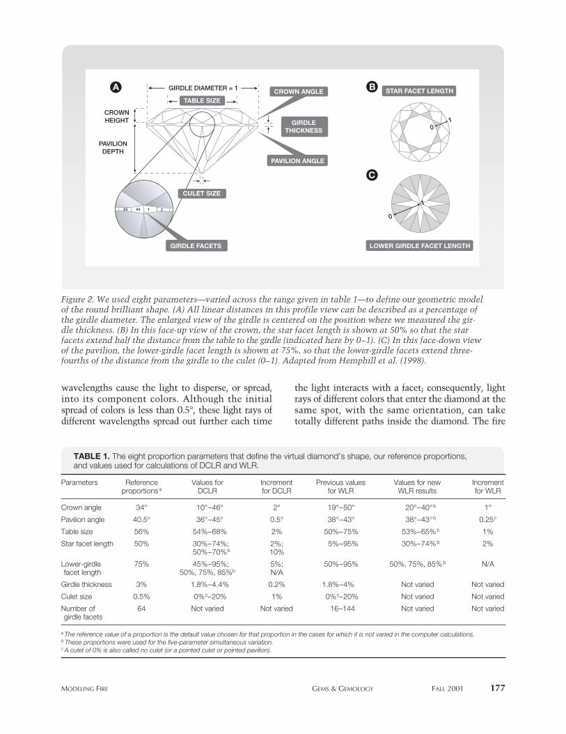
BACKGROUND In Hemphill et al. (1998), we introduced our comput-er model for tracing light rays through a “virtual”diamond—a mathematical representation of a stan-dard, 58-facet, round brilliant cut with a fully facetedgirdle. The virtual diamond has perfect symmetry,so its exact shape can be described with eight param-eters: crown angle, pavilion angle, table size, starfacet length, lower-girdle facet length, culet size, gir-dle thickness, and number of girdle facets (figure 2).We scaled the values of most parameters (e.g., tablepercentage) to the diameter at the girdle, so the vir-tual diamond model applies to diamonds of any size.In addition, the virtual diamond has no inclusions, isperfectly polished, and is completely colorless. Themodel results include the power, position, exit angle,and color (i.e., wavelength) of all traced light rays;these results can be expressed both numerically andgraphically.
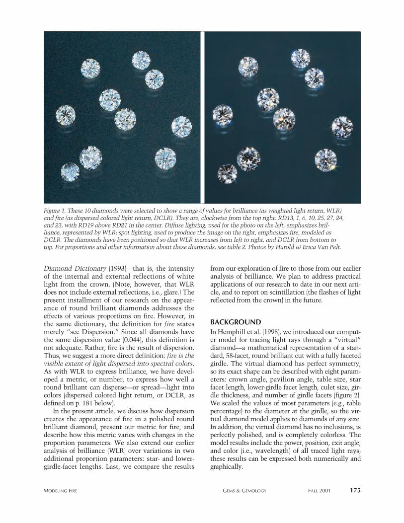
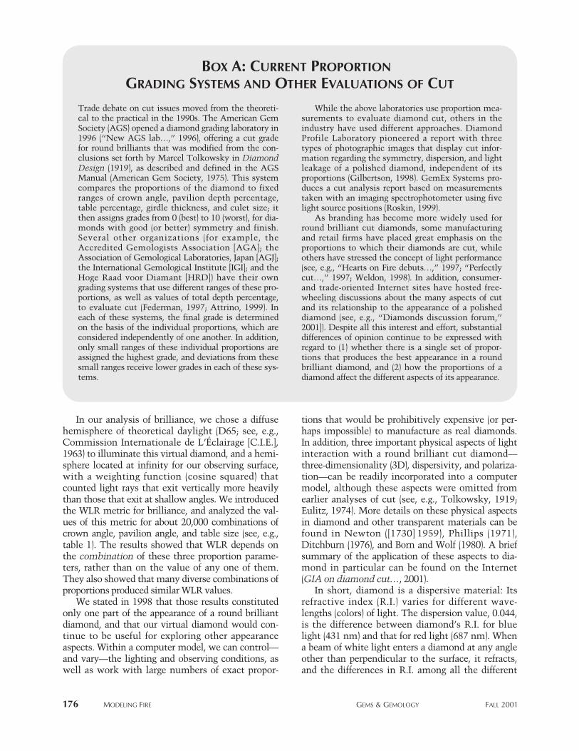
Figure 1. These 10 diamonds were selected to show a range of values for brilliance (as weighted light return, WLR)and fire (as dispersed colored light return, DCLR). They are, clockwise from the top right: RD13, 1, 6, 10, 25, 27, 24,and 23, with RD19 above RD21 in the center. Diffuse lighting, used for the photo on the left, emphasizes bril-liance, represented by WLR; spot lighting, used to produce the image on the right, emphasizes fire, modeled asDCLR. The diamonds have been positioned so that WLR increases from left to right, and DCLR from bottom totop. For proportions and other information about these diamonds, see table 2. Photos by Harold & Erica Van Pelt.
mODeLING FIRe GemS & GemOLOGy FALL 2001 175
In our analysis of brilliance, we chose a diffusehemisphere of theoretical daylight (D65; see, e.g.,Commission Internationale de L’Éclairage [C.I.E.],1963) to illuminate this virtual diamond, and a hemi-sphere located at infinity for our observing surface,with a weighting function (cosine squared) thatcounted light rays that exit vertically more heavilythan those that exit at shallow angles. We introducedthe WLR metric for brilliance, and analyzed the val-ues of this metric for about 20,000 combinations ofcrown angle, pavilion angle, and table size (see, e.g.,table 1). The results showed that WLR depends onthe combination of these three proportion parame-ters, rather than on the value of any one of them.They also showed that many diverse combinations ofproportions produced similar WLR values.
We stated in 1998 that those results constitutedonly one part of the appearance of a round brilliantdiamond, and that our virtual diamond would con-tinue to be useful for exploring other appearanceaspects. Within a computer model, we can control—and vary—the lighting and observing conditions, aswell as work with large numbers of exact propor-
tions that would be prohibitively expensive (or per-haps impossible) to manufacture as real diamonds.In addition, three important physical aspects of lightinteraction with a round brilliant cut diamond—three-dimensionality (3D), dispersivity, and polariza-tion—can be readily incorporated into a computermodel, although these aspects were omitted fromearlier analyses of cut (see, e.g., Tolkowsky, 1919;Eulitz, 1974). More details on these physical aspectsin diamond and other transparent materials can befound in Newton ([1730] 1959), Phillips (1971),Ditchburn (1976), and Born and Wolf (1980). A briefsummary of the application of these aspects to dia-mond in particular can be found on the Internet(GIA on diamond cut…, 2001).
In short, diamond is a dispersive material: Itsrefractive index (R.I.) varies for different wave-lengths (colors) of light. The dispersion value, 0.044,is the difference between diamond’s R.I. for bluelight (431 nm) and that for red light (687 nm). Whena beam of white light enters a diamond at any angleother than perpendicular to the surface, it refracts,and the differences in R.I. among all the different
176 mODeLING FIRe GemS & GemOLOGy FALL 2001
Trade debate on cut issues moved from the theoreti-cal to the practical in the 1990s. The American GemSociety (AGS) opened a diamond grading laboratory in1996 (“New AGS lab…,” 1996), offering a cut gradefor round brilliants that was modified from the con-clusions set forth by Marcel Tolkowsky in DiamondDesign (1919), as described and defined in the AGSManual (American Gem Society, 1975). This systemcompares the proportions of the diamond to fixedranges of crown angle, pavilion depth percentage,table percentage, girdle thickness, and culet size; itthen assigns grades from 0 (best) to 10 (worst), for dia-monds with good (or better) symmetry and finish.Several other organizations (for example, theAccredited Gemologists Association [AGA]; theAssociation of Gemological Laboratories, Japan [AGJ];the International Gemological Institute [IGI]; and theHoge Raad voor Diamant [HRD]) have their owngrading systems that use different ranges of these pro-portions, as well as values of total depth percentage,to evaluate cut (Federman, 1997; Attrino, 1999). Ineach of these systems, the final grade is determinedon the basis of the individual proportions, which areconsidered independently of one another. In addition,only small ranges of these individual proportions areassigned the highest grade, and deviations from thesesmall ranges receive lower grades in each of these sys-tems.
While the above laboratories use proportion mea-surements to evaluate diamond cut, others in theindustry have used different approaches. DiamondProfile Laboratory pioneered a report with threetypes of photographic images that display cut infor-mation regarding the symmetry, dispersion, and lightleakage of a polished diamond, independent of itsproportions (Gilbertson, 1998). GemEx Systems pro-duces a cut analysis report based on measurementstaken with an imaging spectrophotometer using fivelight source positions (Roskin, 1999).
As branding has become more widely used forround brilliant cut diamonds, some manufacturingand retail firms have placed great emphasis on theproportions to which their diamonds are cut, whileothers have stressed the concept of light performance(see, e.g., “Hearts on Fire debuts…,” 1997; “Perfectlycut…,” 1997; Weldon, 1998). In addition, consumer-and trade-oriented Internet sites have hosted free-wheeling discussions about the many aspects of cutand its relationship to the appearance of a polisheddiamond (see, e.g., “Diamonds discussion forum,”2001]). Despite all this interest and effort, substantialdifferences of opinion continue to be expressed withregard to (1) whether there is a single set of propor-tions that produces the best appearance in a roundbrilliant diamond, and (2) how the proportions of adiamond affect the different aspects of its appearance.
Box A: current proportion
grAding systeMs And other evAluAtions of cut
mODeLING FIRe GemS & GemOLOGy FALL 2001 177
wavelengths cause the light to disperse, or spread,into its component colors. Although the initialspread of colors is less than 0.5°, these light rays ofdifferent wavelengths spread out further each time
the light interacts with a facet; consequently, lightrays of different colors that enter the diamond at thesame spot, with the same orientation, can taketotally different paths inside the diamond. The fire
63 64 1 2
GIRDLE DIAMETER = 1
PAVILION DEPTH
CROWN HEIGHT
0
1
10
STAR FACET LENGTH
LOWER GIRDLE FACET LENGTH
GIRDLE THICKNESS
CROWN ANGLE
GIRDLE FACETS
TABLE SIZE
CULET SIZE
PAVILION ANGLE
A B
C
Figure 2. We used eight parameters—varied across the range given in table 1—to define our geometric modelof the round brilliant shape. (A) All linear distances in this profile view can be described as a percentage ofthe girdle diameter. The enlarged view of the girdle is centered on the position where we measured the gir-dle thickness. (B) In this face-up view of the crown, the star facet length is shown at 50% so that the starfacets extend half the distance from the table to the girdle (indicated here by 0–1). (C) In this face-down viewof the pavilion, the lower-girdle facet length is shown at 75%, so that the lower-girdle facets extend three-fourths of the distance from the girdle to the culet (0–1). Adapted from Hemphill et al. (1998).
TABLE 1. The eight proportion parameters that define the virtual diamond’s shape, our reference proportions,and values used for calculations of DCLR and WLR.
Parameters Reference Values for Increment Previous values Values for new Incrementproportionsa DCLR for DCLR for WLR WLR results for WLR
Crown angle 34° 10°–46° 2° 19°–50° 20°–40°b 1°
Pavilion angle 40.5° 36°–45° 0.5° 38°–43° 38°–43°b 0.25°
Table size 56% 54%–68% 2% 50%–75% 53%–65%b 1%
Star facet length 50% 30%–74%; 2%; 5%–95% 30%–74%b 2%50%–70%b 10%
Lower-girdle 75% 45%–95%; 5%; 50%–95% 50%, 75%, 85%b N/Afacet length 50%, 75%, 85%b N/A
Girdle thickness 3% 1.8%–4.4% 0.2% 1.8%–4% Not varied Not varied
Culet size 0.5% 0%c–20% 1% 0%c–20% Not varied Not varied
Number of 64 Not varied Not varied 16–144 Not varied Not variedgirdle facets
a The reference value of a proportion is the default value chosen for that proportion in the cases for which it is not varied in the computer calculations.b These proportions were used for the five-parameter simultaneous variation.c A culet of 0% is also called no culet (or a pointed culet or pointed pavilion).
one observes in a polished diamond is the net resultof this dispersion of light.
In addition, because a round brilliant is made upof flat facets, light becomes partially polarized whenit enters the diamond, and the polarization statethen changes as the light moves within the dia-mond and interacts with several facets. This isimportant because the polarization state of a ray oflight governs how much of its energy is reflected atvarious angles of incidence, for both internal andexternal reflections. The fraction of light thatrefracts and the fraction that reflects internally canbe calculated accurately only by keeping track ofthe light’s polarization state.
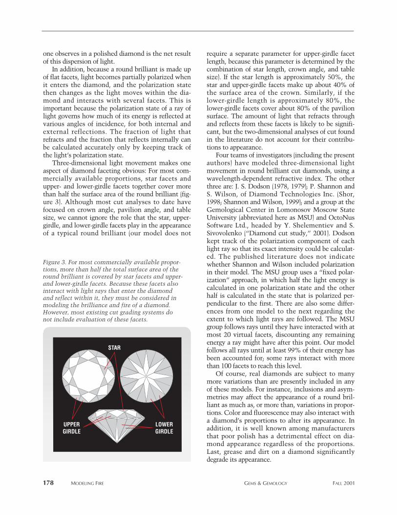
Three-dimensional light movement makes oneaspect of diamond faceting obvious: For most com-mercially available proportions, star facets andupper- and lower-girdle facets together cover morethan half the surface area of the round brilliant (fig-ure 3). Although most cut analyses to date havefocused on crown angle, pavilion angle, and tablesize, we cannot ignore the role that the star, upper-girdle, and lower-girdle facets play in the appearanceof a typical round brilliant (our model does not
require a separate parameter for upper-girdle facetlength, because this parameter is determined by thecombination of star length, crown angle, and tablesize). If the star length is approximately 50%, thestar and upper-girdle facets make up about 40% ofthe surface area of the crown. Similarly, if thelower-girdle length is approximately 80%, thelower-girdle facets cover about 80% of the pavilionsurface. The amount of light that refracts throughand reflects from these facets is likely to be signifi-cant, but the two-dimensional analyses of cut foundin the literature do not account for their contribu-tions to appearance.
Four teams of investigators (including the presentauthors) have modeled three-dimensional lightmovement in round brilliant cut diamonds, using awavelength-dependent refractive index. The otherthree are: J. S. Dodson (1978, 1979); P. Shannon andS. Wilson, of Diamond Technologies Inc. (Shor,1998; Shannon and Wilson, 1999); and a group at theGemological Center in Lomonosov Moscow StateUniversity (abbreviated here as MSU) and OctoNusSoftware Ltd., headed by Y. Shelementiev and S.Sivovolenko (“Diamond cut study,” 2001). Dodsonkept track of the polarization component of eachlight ray so that its exact intensity could be calculat-ed. The published literature does not indicatewhether Shannon and Wilson included polarizationin their model. The MSU group uses a “fixed polar-ization” approach, in which half the light energy iscalculated in one polarization state and the otherhalf is calculated in the state that is polarized per-pendicular to the first. There are also some differ-ences from one model to the next regarding theextent to which light rays are followed. The MSUgroup follows rays until they have interacted with atmost 20 virtual facets, discounting any remainingenergy a ray might have after this point. Our modelfollows all rays until at least 99% of their energy hasbeen accounted for; some rays interact with morethan 100 facets to reach this level.
Of course, real diamonds are subject to manymore variations than are presently included in anyof these models. For instance, inclusions and asym-metries may affect the appearance of a round bril-liant as much as, or more than, variations in propor-tions. Color and fluorescence may also interact witha diamond’s proportions to alter its appearance. Inaddition, it is well known among manufacturersthat poor polish has a detrimental effect on dia-mond appearance regardless of the proportions.Last, grease and dirt on a diamond significantlydegrade its appearance.
178 mODeLING FIRe GemS & GemOLOGy FALL 2001
STAR
UPPER GIRDLE
LOWER GIRDLE
Figure 3. For most commercially available propor-tions, more than half the total surface area of theround brilliant is covered by star facets and upper-and lower-girdle facets. Because these facets alsointeract with light rays that enter the diamondand reflect within it, they must be considered inmodeling the brilliance and fire of a diamond.However, most existing cut grading systems donot include evaluation of these facets.
mODeLING FIRe GemS & GemOLOGy FALL 2001 179
MATERIALS AND METHODS Computation. For this work, we began with thesame proprietary computer programs we used previ-ously, and wrote several more computer routines torepresent additional light sources and to calculateresults relevant to the dispersion of light. As we didin 1998, we verified these new programs by runninga test program for which the solution was foundmanually. Our programs run on any computer thataccepts programs written in C; we used 16 PentiumIII and four Pentium II processors in conventionaldesktop computers to carry out the calculations pre-sented here. With these programs, we calculated thefire metric (DCLR) for more than 26,000 round bril-liant proportion combinations (again, see table 1).On average, these calculations took 1.5–2 processorhours each.
Starting with 5,733 typical combinations of
crown angle, pavilion angle, and table size (from theranges used in Hemphill et al., 1998), we also calcu-lated WLR values with various star and lower-girdlefacet lengths, keeping girdle thickness, culet size, andthe number of girdle facets fixed at our reference pro-portions (again, see table 1). This resulted in 395,577additional WLR values, using 23 star facet lengths(from 30%–74%, in increments of 2%), and threelower-girdle facet lengths (short—50%, medium—75%, and long—85%). The medium and long lowerfacet lengths were chosen as typical values seen inthe trade today, while the short (50%) value was cho-sen because this is the lower-girdle lengthTolkowsky (1919) used (see also Green et al., 2001).
Diamonds. We obtained (or had manufactured) 28round brilliant diamonds (0.44–0.89 ct), some withunconventional proportions (see table 2). The 45“view from infinity” (VFI) diagrams described below
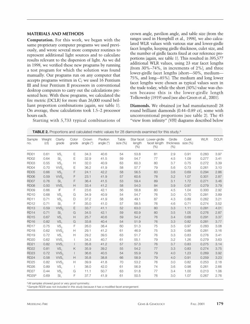
TABLE 2. Proportions and calculated metric values for 28 diamonds examined for this study.a
Sample Weight Clarity Color Crown Pavilion Table Star facet Lower-girdle Girdle Culet WLR DCLRno. (ct) grade grade angle (°) angle (°) size (%) length facet length thickness size (%)
(%) (%) (%)
RD01 0.61 VS1 E 34.3 40.6 54 53.8 81 2.9 0.91 0.283 3.97RD02 0.64 SI2 E 32.9 41.5 59 54.7 77 4.5 1.09 0.277 3.41RD03 0.55 VS2 H 32.0 40.9 63 60.3 80 3.7 0.75 0.272 3.39RD04 0.70 VVS2 E 36.2 41.9 58 57.7 79 5.6 0.73 0.261 3.10RD05 0.66 VS2 F 24.1 42.2 58 56.5 83 3.6 0.69 0.294 2.86RD06 0.59 VVS2 F 23.1 41.9 57 60.6 78 3.2 1.07 0.301 2.87RD07 0.76 SI1 F 36.4 41.5 53 59.4 89 3.1 1.72 0.271 3.46RD08 0.50 VVS1 H 33.4 41.2 58 54.0 84 3.9 0.97 0.279 3.79RD09 0.66 IF F 23.6 42.1 56 58.8 80 4.5 1.04 0.300 2.92RD10 0.68 VS2 G 34.9 40.9 54 54.7 76 3.0 0.70 0.281 3.89RD11 0.71 VS2 D 37.2 41.9 58 49.1 87 4.3 0.89 0.262 3.21RD12 0.71 SI1 F 35.0 41.0 57 58.5 76 4.6 0.71 0.274 3.52RD13 0.59 VVS2 E 33.7 41.1 52 63.0 80 3.3 1.11 0.281 4.01RD14 0.71 SI1 G 34.5 42.1 59 60.9 80 3.5 1.05 0.276 2.87RD15 0.67 VS1 H 25.7 40.6 59 54.2 76 3.4 0.68 0.291 3.37RD16 0.82 VS1 G 33.8 40.4 54 51.9 76 3.3 0.82 0.281 3.77RD17 0.75 VS2 F 26.0 38.4 60 51.3 75 3.5 0.97 0.283 3.08RD18 0.62 VVS2 H 29.1 41.2 61 46.9 75 3.3 0.88 0.281 3.16RD19 0.72 VS1 H 29.2 39.5 63 51.7 76 3.3 0.83 0.276 3.41RD20 0.62 VVS1 I 34.3 40.7 61 55.1 79 3.2 1.26 0.279 3.63RD21 0.82 VVS1 I 35.8 41.2 57 57.3 76 3.7 0.83 0.275 3.14RD22 0.81 VS1 K 35.9 39.2 55 54.2 77 3.3 0.83 0.274 3.75RD23 0.72 VVS2 I 36.6 40.5 54 55.9 79 4.0 1.23 0.269 3.92RD24 0.58 VVS1 H 35.8 38.8 66 58.9 79 4.0 0.91 0.259 3.23RD25 0.82 VVS2 H 39.9 41.8 70 53.2 76 3.0 0.82 0.253 2.18RD26 0.89 VS1 I 38.0 42.0 61 56.9 74 3.6 0.98 0.261 2.66RD27 0.44 VS2 G 11.1 50.7 63 51.8 77 3.4 1.00 0.213 1.06RD29b 0.69 SI1 F 37.7 41.9 61 50.5 76 3.0 1.07 0.267 2.76
aAll samples showed good or very good symmetry.bSample RD28 was not included in this study because it has a modified facet arrangement.

were calculated for these 28 diamonds and for anoth-er 17 diamonds (in the same weight range) with verygood or excellent symmetry and polish that werechosen at random from those graded at the GIA GemTrade Laboratory (GIA GTL). We examined andrecorded dispersed patterns of colored light (see nextsection) for these diamonds and for more than 400round brilliants chosen from the same GIA GTL pop-ulation using the same symmetry and polish criteria.
Conditions for Observing Fire. To analyze bril-liance, we chose the diffuse lighting condition wereported on in 1998, specifically because it maxi-mized the effects of white light return while mini-mizing the impact of fire and contrast. However,because this lighting condition suppresses fire, itwould not be appropriate for exploring the effect ofproportion combinations on this appearance aspect.Again, fire in a round brilliant is the display of purespectral hues that arise because the diamond isbehaving like a prism, dispersing white light into itscolor components. Fire is not seen as a uniformcolor across the entire crown of the diamond at
once, or as a single rainbow, but as localized flashesof various colors that change depending on the posi-tion from which the diamond is viewed.
Keeping these aspects in mind, we began oursearch for a suitable lighting condition with theobservation that diamonds look fiery under bothsunlight and spot lights (such as the halogen lightsfound in many retail stores). This lighting is direct-ed, that is, it comes from a very small area (relative-ly speaking), in contrast to diffuse lighting, whichcomes from all directions (such as outdoors on afoggy day, or fluorescent lighting reflected off whiteceilings). These impressions were further supportedby our experience photographing polished diamondsto capture their displays of fire. With either film or adigital camera, we found that a source of directedlight was needed (in combination with diffusedtungsten photography lights) to see fire in a photo-graphic image (again, see figure 1).
Tolkowsky (1919) suggested a way to view firefrom a diamond, that is, by using a sheet of paperwith a pinhole. Light shining through the hole in thepaper falls on the table of the diamond, and dispersedlight that returns through the crown can be observedon the side of the paper facing the diamond. In suchan illumination geometry, however, angular rela-tionships are distorted, and the distance between thediamond and the paper strongly affects how much ofthe light returning through the crown is visible.
Using the same general idea, we created an appa-ratus to view and capture images of dispersed lightfrom actual diamonds. As shown in figure 4, weintroduced light through a 0.95 cm hole in a whiteplastic hemisphere (40.6 cm [16 inches] in diameter),which was the observing surface. We used a Luminafiber-optic light, model Fo-150, which has a colortemperature of 2920 K, and placed it approximately20 cm from the hole, so that a preponderance of thelight rays falling on the diamond were parallel to oneanother. The beam of light was centered on the dia-mond’s table, and perpendicular to it. The diameterof this hemisphere was about 70 times larger thanthat of the diamonds we examined. The light emerg-ing from the diamond could be viewed on the hemi-sphere, or recorded as a photograph, such as the oneshown in figure 5.
We call the colored patches on the surface of thehemisphere chromatic flares. (In contrast, fire isseen when we observe the diamond directly.)Observation of chromatic flares requires an edge tothe light source, specifically, a strong differencebetween light and dark: The dark portion con-tributes no color, so dispersion is emphasized.
180 mODeLING FIRe GemS & GemOLOGy FALL 2001
Figure 4. This experimental design allowed us toobserve dispersed light from actual diamonds. Awhite hemisphere 40.6 cm (16 inches) in diameteris used as the observing surface, and a 0.95 cmhole at the center allows light from behind thehemisphere to shine on a diamond. The round bril-liant is centered in the beam of light, with its gir-dle as close as feasible to the plane of the hemi-sphere’s rim and its table oriented perpendicular tothe beam. The light source is located about 20 cmbehind the hole, so that light shining on the dia-mond is largely composed of parallel rays. Sizesand distances in this diagram are not to scale.

mODeLING FIRe GemS & GemOLOGy FALL 2001 181
Many of the flares are quite small, but some arewide, or long, or both (again, see figure 5). Any par-ticular chromatic flare may include the whole spec-trum of colors or only a few of them. Furthermore,if the dome is increased in size, most flares mayspread out. The overall light level in the roomstrongly affects how many chromatic flares anobserver sees; we saw many more flares in the domein a darkened room than with the room lights on.
We used a Minolta X700 camera with a 45-mmlens, ASA 100 film, and an f-stop of 18 to take pho-tographs of light dispersed from real diamonds.Exposure times varied from 45 to 150 seconds. Weexamined and recorded dispersed patterns of coloredlight for the more than 400 round brilliants men-tioned earlier, to gain an understanding of the rangeof appearances of chromatic flares, and thus of firein polished diamonds.
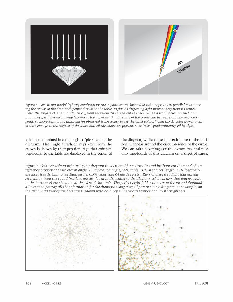
Model Conditions for Fire. We chose to modeldirected lighting as a bright point source of D65 illu-mination (a common model for average daylight;see again C.I.E., 1963), located very far from the dia-mond (at infinite distance) and centered over thediamond’s table. With this condition, the unpolar-ized light rays entering the crown facets are parallelto one another and perpendicular to the table (figure6, left). The entire crown is illuminated.
An observer position also needed to be deter-mined. As the distance between the observer andthe diamond increases, the observer sees less whitelight and more dispersed colors, but he or she cansee only some of the colors at one time (figure 6,right). Conversely, when a round brilliant is viewedclose up, the fire is less discernable since variouscolors viewed close together appear as white light.(This effect also was demonstrated in our apparatusfor observing chromatic flares from actual dia-monds, where some of the dispersed light outputfrom the diamonds appeared as white light.)Therefore, to observe maximum fire, the observermust be as far away from the diamond as possible.In addition, the assessment of fire requires multipleviews of the diamond, from different viewingangles. (The fact that these multiple views cannotbe made simultaneously, but must be made sequen-tially from various positions, may complicate theassessment of fire in a diamond by an “actual”observer, but can be incorporated relatively easily ina model.) Our “observer” for WLR was a hemi-sphere at infinity (with a cosine squared weightingfunction for the returned light), and we found thatthis observer was a good choice for viewing fire as
well. This model observer “views” the virtual dia-mond from all angles, while the weighting factorincorporates the importance of the face-up position.This combination of lighting and observing condi-tions tests the maximum extent to which a roundbrilliant with a particular choice of proportions candisperse light into its component colors.
A Metric for Fire: DCLR. To analyze the fire from avirtual diamond graphically, we plotted the modeloutput of our observing hemisphere, projected onto aflat plane, using a polar projection in which the dis-tance of any plotted point from the center of the dia-gram is proportional to the exit angle of that ray. Wecall this graphic result a view from infinity (VFI) dia-gram. The combination of point light source and infi-nite viewing distance yields only dispersed light onthe observing hemisphere; that is, the result appearsas various colored streaks (with no white centers).These streaks are composed of colored spots showingthe final exit directions of individual rays. The col-ored streaks on a VFI diagram for a virtual diamondcorrespond to the chromatic flares on the hemispherefor an actual diamond of the same proportions.
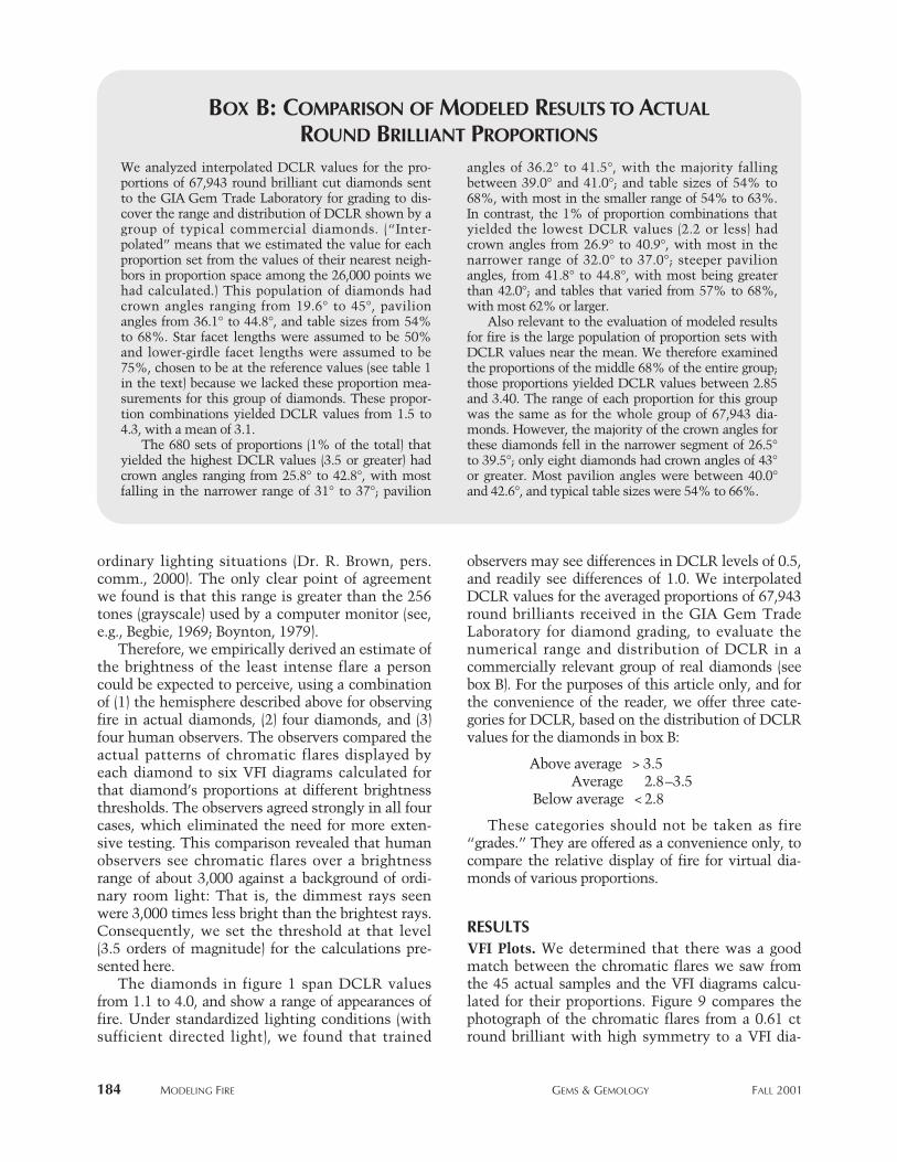
Figure 7 shows a complete VFI diagram for a vir-tual round brilliant cut diamond of our referenceproportions. For a diamond with perfect symmetry(such as our virtual diamond), all of this information
Figure 5. This image shows a variety of chromaticflares (colored light patterns) that were produced by around brilliant diamond on our observation hemi-sphere. Larger images of two chromatic flares, shownas insets, illustrate some of the variety seen in thesepatterns. Photo by Al Gilbertson.
is in fact contained in a one-eighth “pie slice” of thediagram. The angle at which rays exit from thecrown is shown by their position; rays that exit per-pendicular to the table are displayed in the center of
the diagram, while those that exit close to the hori-zontal appear around the circumference of the circle.We can take advantage of the symmetry and plotonly one-fourth of this diagram on a sheet of paper,
182 mODeLING FIRe GemS & GemOLOGy FALL 2001
Figure 6. Left: In our model lighting condition for fire, a point source located at infinity produces parallel rays enter-ing the crown of the diamond, perpendicular to the table. Right: As dispersing light moves away from its source(here, the surface of a diamond), the different wavelengths spread out in space. When a small detector, such as ahuman eye, is far enough away (shown as the upper oval), only some of the colors can be seen from any one view-point, so movement of the diamond (or observer) is necessary to see the other colors. When the detector (lower oval)is close enough to the surface of the diamond, all the colors are present, so it “sees” predominantly white light.
DIAMONDAIR
Figure 7. This “view from infinity” (VFI) diagram is calculated for a virtual round brilliant cut diamond of ourreference proportions (34° crown angle, 40.5° pavilion angle, 56% table, 50% star facet length, 75% lower-gir-dle facet length, thin to medium girdle, 0.5% culet, and 64 girdle facets). Rays of dispersed light that emergestraight up from the round brilliant are displayed in the center of the diagram, whereas rays that emerge closeto the horizontal are shown near the edge of the circle. The perfect eight-fold symmetry of the virtual diamondallows us to portray all the information for the diamond using a small part of such a diagram. For example, onthe right, a quarter of the diagram is shown with each ray’s line width proportional to its brightness.

mODeLING FIRe GemS & GemOLOGy FALL 2001 183
with the different intensities of the rays appearing asdifferent plotted thicknesses (figure 7, right).
We calculated VFI diagrams for proportion com-binations taken from 45 actual diamonds, to com-pare with their observed dispersion patterns. (Thedetailed measurements of each round brilliant wereaveraged to produce a symmetrical proportion com-bination for that diamond.) Figure 8 shows threeactual diamonds with different proportions as wellas the VFI diagrams calculated for them. Althoughthese color-streak patterns look different, we had noway to evaluate these VFI images quantitatively: thediamonds appear to show comparable fire. We need-ed a numerical value—that is, a metric—that couldbe used to evaluate fire for thousands of proportioncombinations. It was important that the metricincorporate factors that matter to people when theyobserve fire in round brilliants; it also had to producenumerical values that differentiate a very fiery dia-mond from one with little fire.
The VFI diagrams display a variety of propertiesthat can be combined into a metric, such as thetotal number and relative brightness of coloredspots, and the lengths and angular distribution ofthe colored streaks made up of these spots. Themetric we derived—dispersed colored light return,or DCLR—describes the potential of a round bril-liant diamond with given proportions to display dis-persed light when viewed face-up. Mathematically,DCLR is defined as:
DCLR = Σstreaks Σcolors (Area × Smoothed Intensity
×Weighting Factor)
That is, DCLR is the sum over all colored streaks,of the sum over all colors (sampled every 10 nm; seeagain C.I.E., 1963), of the size (area) of each coloredstreak multiplied times the “smoothed”∗ brightness(intensity) of each spot along the streak, times anexit-angle weighting factor (the square of the cosineof the ray’s exit angle, which we also used for WLR).
The VFI diagrams show additional propertiesthat we chose not to include in DCLR. For example,
we included the angular distribution of the coloredstreaks in this metric, but not a radial term (whichwould have, e.g., differentiated flares coming frombezel facets from flares coming from star facets),because we believe that a human observer caresabout fire from the diamond as a whole. Similarly,we did not use the color distribution within a givenstreak (that is, whether it contains a whole rainbowor only a few colors) or the orientation of a streak,choosing instead to focus on the overall impact ofcolored flashes. Last, we did not consider the colordistribution of the spots (i.e., the relative number ofred spots to green, yellow, or blue spots), becausethe various VFI diagrams we plotted showed bal-anced representations of all colors, a property wealso observed in real diamonds.
Before starting the calculations, we needed toestablish an appropriate brightness threshold forDCLR, to determine the range between the bright-est and dimmest rays a person could be expectedto see against a generally bright background (as inthe light we typically use in our homes or offices,whether fluorescent or incandescent). The scientif-ic literature dealing with human vision containsseveral works about the least amount of light thatcan be seen, or the brightest light in which objectscan be discriminated, but almost nothing aboutthe range of light levels perceived by humans in
Figure 8. These three diamonds (0.50–0.64 ct) haverather different proportions (crown, pavilion, andtable given here), and the VFI diagrams calculated fortheir proportions show different patterns. However,all three diamonds appear bright and display compa-rable fire. Photo by Elizabeth Schrader.
C 23.1°/P 41.9°/T 57% C 34.1°/P 41.3°/T 58% C 32.9°/ P 41.5°/T 59%
∗We used a smoothing function because the intensity of calculat-ed colored spots varied over a large range. Although we wantedbrighter rays to count more than dimmer rays, we did not wantthe large scale of these numbers to overwhelm other factors, suchas the area. Thus, rather than use the intensity directly, we“smoothed” it with an “S-shaped” function. The center of the“S” set the intensity of colored streaks to be included, based ontheir brightness relative to the strongest rays, and the smoothedfunction avoided an abrupt transition between the included raysand slightly dimmer excluded rays.
ordinary lighting situations (Dr. R. Brown, pers.comm., 2000). The only clear point of agreementwe found is that this range is greater than the 256tones (grayscale) used by a computer monitor (see,e.g., Begbie, 1969; Boynton, 1979).
Therefore, we empirically derived an estimate ofthe brightness of the least intense flare a personcould be expected to perceive, using a combinationof (1) the hemisphere described above for observingfire in actual diamonds, (2) four diamonds, and (3)four human observers. The observers compared theactual patterns of chromatic flares displayed byeach diamond to six VFI diagrams calculated forthat diamond’s proportions at different brightnessthresholds. The observers agreed strongly in all fourcases, which eliminated the need for more exten-sive testing. This comparison revealed that humanobservers see chromatic flares over a brightnessrange of about 3,000 against a background of ordi-nary room light: That is, the dimmest rays seenwere 3,000 times less bright than the brightest rays.Consequently, we set the threshold at that level(3.5 orders of magnitude) for the calculations pre-sented here.
The diamonds in figure 1 span DCLR valuesfrom 1.1 to 4.0, and show a range of appearances offire. Under standardized lighting conditions (withsufficient directed light), we found that trained
observers may see differences in DCLR levels of 0.5,and readily see differences of 1.0. We interpolatedDCLR values for the averaged proportions of 67,943round brilliants received in the GIA Gem TradeLaboratory for diamond grading, to evaluate thenumerical range and distribution of DCLR in acommercially relevant group of real diamonds (seebox B). For the purposes of this article only, and forthe convenience of the reader, we offer three cate-gories for DCLR, based on the distribution of DCLRvalues for the diamonds in box B:
Above average > 3.5Average 2.8–3.5
Below average < 2.8
These categories should not be taken as fire“grades.” They are offered as a convenience only, tocompare the relative display of fire for virtual dia-monds of various proportions.
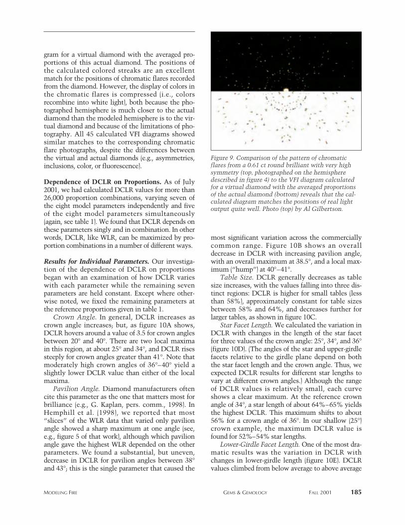
RESULTSVFI Plots. We determined that there was a goodmatch between the chromatic flares we saw fromthe 45 actual samples and the VFI diagrams calcu-lated for their proportions. Figure 9 compares thephotograph of the chromatic flares from a 0.61 ctround brilliant with high symmetry to a VFI dia-
184 mODeLING FIRe GemS & GemOLOGy FALL 2001
Box B: coMpArison of Modeled results to ActuAl
round BrilliAnt proportions
We analyzed interpolated DCLR values for the pro-portions of 67,943 round brilliant cut diamonds sentto the GIA Gem Trade Laboratory for grading to dis-cover the range and distribution of DCLR shown by agroup of typical commercial diamonds. (“Inter -polated” means that we estimated the value for eachproportion set from the values of their nearest neigh-bors in proportion space among the 26,000 points wehad calculated.) This population of diamonds hadcrown angles ranging from 19.6° to 45°, pavilionangles from 36.1° to 44.8°, and table sizes from 54%to 68%. Star facet lengths were assumed to be 50%and lower-girdle facet lengths were assumed to be75%, chosen to be at the reference values (see table 1in the text) because we lacked these proportion mea-surements for this group of diamonds. These propor-tion combinations yielded DCLR values from 1.5 to4.3, with a mean of 3.1.
The 680 sets of proportions (1% of the total) thatyielded the highest DCLR values (3.5 or greater) hadcrown angles ranging from 25.8° to 42.8°, with mostfalling in the narrower range of 31° to 37°; pavilion
angles of 36.2° to 41.5°, with the majority fallingbetween 39.0° and 41.0°; and table sizes of 54% to68%, with most in the smaller range of 54% to 63%.In contrast, the 1% of proportion combinations thatyielded the lowest DCLR values (2.2 or less) hadcrown angles from 26.9° to 40.9°, with most in thenarrower range of 32.0° to 37.0°; steeper pavilionangles, from 41.8° to 44.8°, with most being greaterthan 42.0°; and tables that varied from 57% to 68%,with most 62% or larger.
Also relevant to the evaluation of modeled resultsfor fire is the large population of proportion sets withDCLR values near the mean. We therefore examinedthe proportions of the middle 68% of the entire group;those proportions yielded DCLR values between 2.85and 3.40. The range of each proportion for this groupwas the same as for the whole group of 67,943 dia-monds. However, the majority of the crown angles forthese diamonds fell in the narrower segment of 26.5°to 39.5°; only eight diamonds had crown angles of 43°or greater. Most pavilion angles were between 40.0°and 42.6°, and typical table sizes were 54% to 66%.
mODeLING FIRe GemS & GemOLOGy FALL 2001 185
gram for a virtual diamond with the averaged pro-portions of this actual diamond. The positions ofthe calculated colored streaks are an excellentmatch for the positions of chromatic flares recordedfrom the diamond. However, the display of colors inthe chromatic flares is compressed (i.e., colorsrecombine into white light), both because the pho-tographed hemisphere is much closer to the actualdiamond than the modeled hemisphere is to the vir-tual diamond and because of the limitations of pho-tography. All 45 calculated VFI diagrams showedsimilar matches to the corresponding chromaticflare photographs, despite the differences betweenthe virtual and actual diamonds (e.g., asymmetries,inclusions, color, or fluorescence).
Dependence of DCLR on Proportions. As of July2001, we had calculated DCLR values for more than26,000 proportion combinations, varying seven ofthe eight model parameters independently and fiveof the eight model parameters simultaneously(again, see table 1). We found that DCLR depends onthese parameters singly and in combination. In otherwords, DCLR, like WLR, can be maximized by pro-portion combinations in a number of different ways.
Results for Individual Parameters. Our investiga-tion of the dependence of DCLR on proportionsbegan with an examination of how DCLR varieswith each parameter while the remaining sevenparameters are held constant. Except where other-wise noted, we fixed the remaining parameters atthe reference proportions given in table 1.
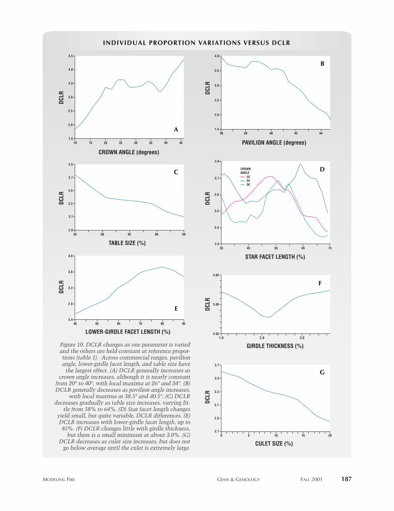
Crown Angle. In general, DCLR increases ascrown angle increases; but, as figure 10A shows,DCLR hovers around a value of 3.5 for crown anglesbetween 20° and 40°. There are two local maximain this region, at about 25° and 34°, and DCLR risessteeply for crown angles greater than 41°. Note thatmoderately high crown angles of 36°–40° yield aslightly lower DCLR value than either of the localmaxima.
Pavilion Angle. Diamond manufacturers oftencite this parameter as the one that matters most forbrilliance (e.g., G. Kaplan, pers. comm., 1998). InHemphill et al. (1998), we reported that most“slices” of the WLR data that varied only pavilionangle showed a sharp maximum at one angle (see,e.g., figure 5 of that work), although which pavilionangle gave the highest WLR depended on the otherparameters. We found a substantial, but uneven,decrease in DCLR for pavilion angles between 38°and 43°; this is the single parameter that caused the
most significant variation across the commerciallycommon range. Figure 10B shows an overalldecrease in DCLR with increasing pavilion angle,with an overall maximum at 38.5°, and a local max-imum (“hump”) at 40°–41°.
Table Size. DCLR generally decreases as tablesize increases, with the values falling into three dis-tinct regions: DCLR is higher for small tables (lessthan 58%), approximately constant for table sizesbetween 58% and 64%, and decreases further forlarger tables, as shown in figure 10C.
Star Facet Length. We calculated the variation inDCLR with changes in the length of the star facetfor three values of the crown angle: 25°, 34°, and 36°(figure 10D). (The angles of the star and upper-girdlefacets relative to the girdle plane depend on boththe star facet length and the crown angle. Thus, weexpected DCLR results for different star lengths tovary at different crown angles.) Although the rangeof DCLR values is relatively small, each curveshows a clear maximum. At the reference crownangle of 34°, a star length of about 64%–65% yieldsthe highest DCLR. This maximum shifts to about56% for a crown angle of 36°. In our shallow (25°)crown example, the maximum DCLR value isfound for 52%–54% star lengths.
Lower-Girdle Facet Length. One of the most dra-matic results was the variation in DCLR withchanges in lower-girdle length (figure 10E). DCLRvalues climbed from below average to above average
Figure 9. Comparison of the pattern of chromaticflares from a 0.61 ct round brilliant with very highsymmetry (top, photographed on the hemispheredescribed in figure 4) to the VFI diagram calculatedfor a virtual diamond with the averaged proportionsof the actual diamond (bottom) reveals that the cal-culated diagram matches the positions of real lightoutput quite well. Photo (top) by Al Gilbertson.
as the length of the lower-girdle facets increasedfrom 45% to 85%, but then fell as this parameterfurther increased to 95%. As the lower-girdle facetsget longer, they make a shallower angle with thegirdle plane (closer to the pavilion angle) and veryslightly shallower angles with each other and withthe pavilion mains on either side. They also causethe pavilion mains to be narrower.
Girdle Thickness and Culet Size. DCLR showedvery little change over the whole range of girdlethickness, with a slight minimum for a medium gir-dle (figure 10F). DCLR drops fairly smoothly asculet size increases from none to extremely large(figure 10G).
Combined Effects. Ideally, we would like to haveshown the combined effects of crown angle, pavil-ion angle, table size, and star and lower-girdle facetlength on DCLR in one graphic image. However,only two of these independent proportion variablescan be displayed with the complete variation of adependent value (such as DCLR) on a single graph.One way to illustrate the effects of two parametersis to draw contours showing ranges of DCLR values,similar to the WLR contours in Hemphill et al.(1998, figures 7–11). The “peaks” on such a contourplot represent proportion combinations that pro-duce the highest calculated DCLR values. By group-ing several contour plots together, we can show theresults when two additional proportions are varied.
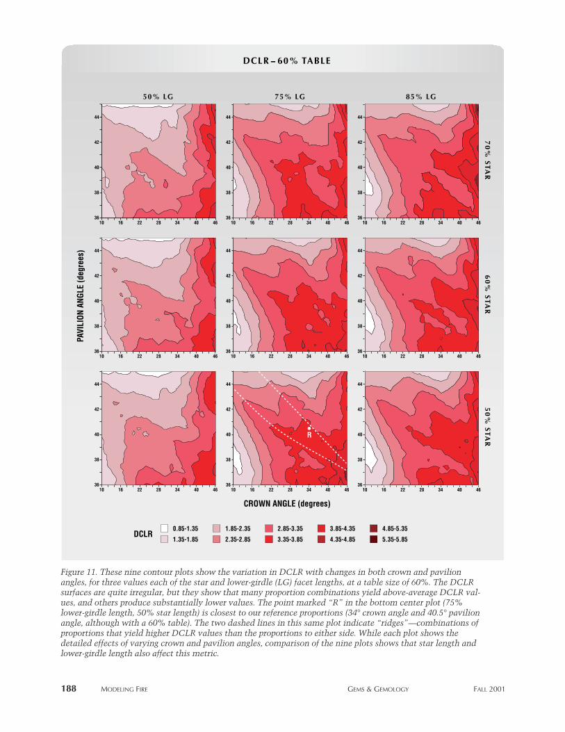
The nine contour plots in figure 11 show DCLRvalues with variations in both crown angle and pavil-ion angle, for a table size of 60%. They also demon-strate the effects of varying star and lower-girdle facetlength, for three values of each. This figure contains alarge amount of information about how these propor-tions work together to change DCLR.
The graph in the bottom center of figure 11 con-tains the point closest to our reference proportions(i.e., 34° crown angle and 40.5° pavilion angle),marked “R”, with a DCLR of 3.38. For this 60%table size, 50% star, and 75% lower-girdle facetlength, the highest DCLR values are found at lowpavilion angles of 36°–37° and a high crown angleof 46°. DCLR decreases sharply for most crownangles at high pavilion angles (greater than 42°).However, the DCLR at shallow crown anglesdepends strongly on the pavilion angle as well.
Within the proportion space shown on this bot-tom center plot, there are two “ridges” of higherDCLR. These ridges represent combinations ofcrown and pavilion angles that work together toproduce higher DCLR. One ridge ends at about a
16° crown angle and a 43° pavilion angle; DCLRdecreases from there for both shallower and steeperpavilion angles. The other ridge, to the right, isbroader and less distinct in this specific plot.
As we compare the topography shown on thisplot with that of each of the other eight plots in fig-ure 11, we can see: (1) the strong effect of lower-gir-dle facet length on DCLR (compare plots left-to-right); and (2) the weaker, but still significant, effectof different star facet lengths (compare plots top-to-bottom). Shorter lower-girdle facets greatly decreaseDCLR for most combinations of crown and pavilionangle, with a few exceptions (e.g., for crown anglesgreater than 40°, or for crown angles of 22°–46°with pavilion angles of less than 37°). Longer lower-girdle facets yield a large number of crown andpavilion angle combinations with average or above-average DCLR.
In a broad region (i.e., with crown angles from 16°to 46° and pavilion angles from 36° to about 43°), thecombination of star and lower-girdle facet lengthschanges the location of the two ridges of higherDCLR, and alters the depth of the valley betweenthe ridges. Overall, the center plot (for 60% star and75% lower-girdle facet length) shows the largestnumber of crown and pavilion angle combinationsthat yield average and above-average DCLR values,but the upper-right plot (for 70% star and 85%lower-girdle facet length) shows the most combina-tions that yield DCLR values of 4.0 or higher.
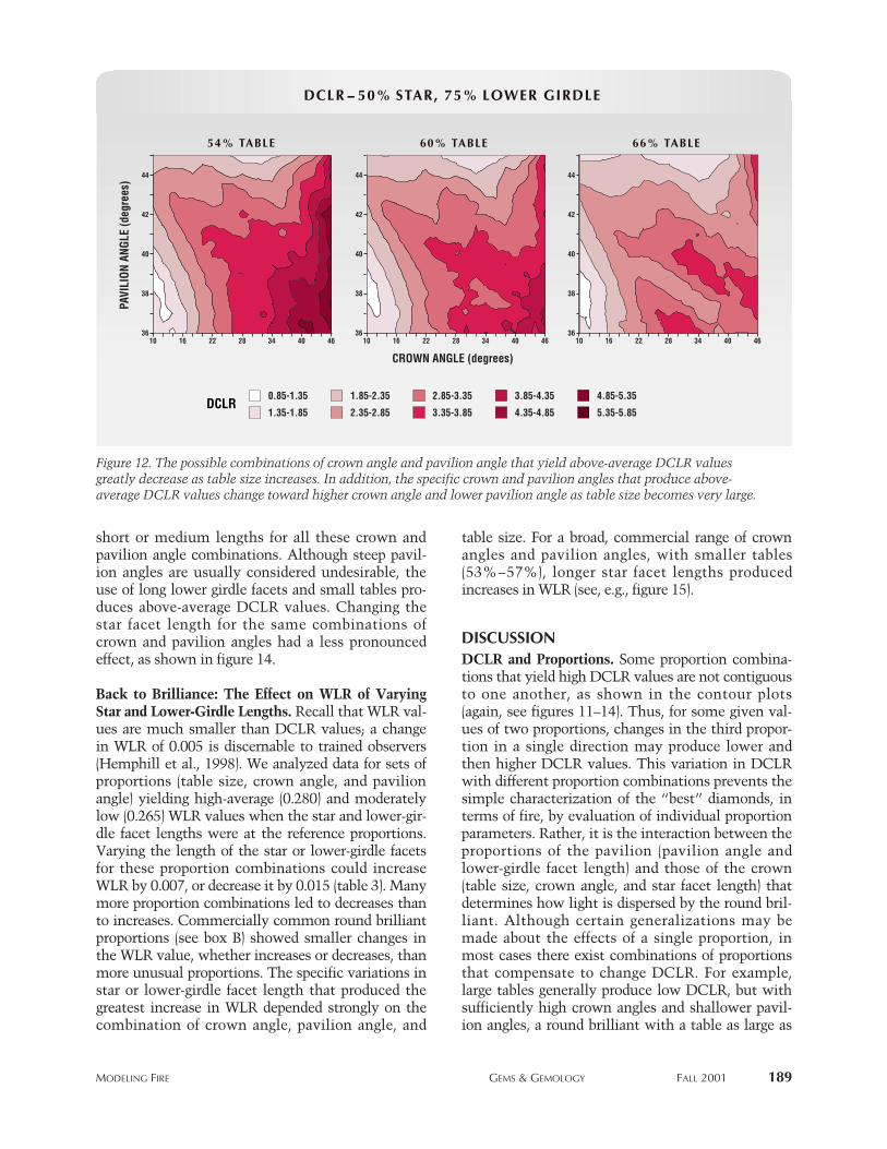
The fifth proportion we varied was table size. Thethree regions found for DCLR variations with tablesize alone (i.e., high for small tables, approximatelyconstant for table sizes between 58% and 62%, andlower for larger tables in figure 10C) held true for themost part in the multi-dimensional exploration aswell. Figure 12 shows three contour plots for 54%(small), 60% (medium), and 66% (large) table sizes,with 50% star and 75% lower-girdle facet lengths(the reference values). Many more combinations ofcrown and pavilion angles with small tables yieldedaverage or greater DCLR values than those with largetables. Although there were many crown and pavil-ion angle combinations that yielded these DCLR val-ues with a 60% table, on average DCLR values werelower than with a small table. For large tables, only anarrow range of pavilion angles (shallower than typi-cal) produced these DCLR values.
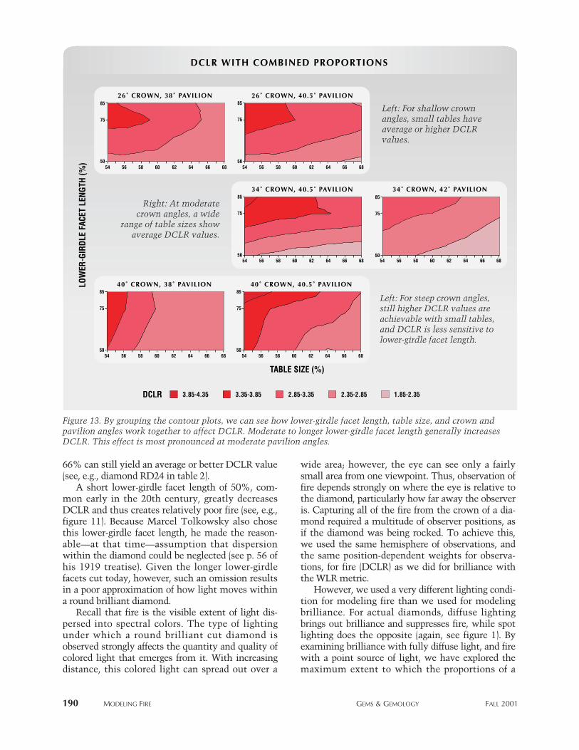
The combined effects of table size and lower-gir-dle facet length are shown in figure 13 for severalsignificant combinations of crown and pavilionangle. We found that longer lower-girdle facetlengths generally yield higher DCLR values than
186 mODeLING FIRe GemS & GemOLOGy FALL 2001
mODeLING FIRe GemS & GemOLOGy FALL 2001 187
INDIVIDUAL PROPORTION VARIATIONS VERSUS DCLRINDIVIDUAL PROPORTION VARIATIONS VERSUS DCLR
DCLR
PAVILION ANGLE (degrees)
4442403836
4.0
3.5
3.0
2.0
1.5
2.5
BBDC
LR
LOWER-GIRDLE FACET LENGTH (%)
958575655545
2.8
2.4
4.0
3.6
3.2
EE
DCLR
TABLE SIZE (%)
6866625854
3.5
3.7
3.5
3.1
2.9
3.3
CC
DCLR
4540353025201510
4.5
4.0
3.5
3.0
2.0
1.5
2.5
AA
CROWN ANGLE (degrees)
DCLR
7565554535
3.8
3.7
3.6
3.4
3.3
3.5
DD
34˚ 25˚
36˚
CROWN ANGLE
STAR FACET LENGTH (%)
DCLR
3.82.81.8
3.65
3.60
3.55
FF
GIRDLE THICKNESS (%)
DCLR
CULET SIZE (%)20151050
3.7
3.5
3.3
2.9
2.7
3.1
GG
Figure 10. DCLR changes as one parameter is variedand the others are held constant at reference propor-tions (table 1). Across commercial ranges, pavilionangle, lower-girdle facet length, and table size havethe largest effect. (A) DCLR generally increases as
crown angle increases, although it is nearly constantfrom 20° to 40°, with local maxima at 26° and 34°. (B)DCLR generally decreases as pavilion angle increases,
with local maxima at 38.5° and 40.5°. (C) DCLRdecreases gradually as table size increases, varying lit-
tle from 58% to 64%. (D) Star facet length changesyield small, but quite variable, DCLR differences. (E)DCLR increases with lower-girdle facet length, up to85%. (F) DCLR changes little with girdle thickness,but there is a small minimum at about 3.0%. (G)
DCLR decreases as culet size increases, but does notgo below average until the culet is extremely large.
188 mODeLING FIRe GemS & GemOLOGy FALL 2001
PAVI
LION
ANG
LE (d
egre
es)
CROWN ANGLE (degrees)
DCLR -- 60% TABLEDCLR -- 60% TABLE
DCLR
70
% STA
R
70
% STA
R
60
% STA
R
60
% STA
R
50
% STA
R
50
% STA
R
50% LG50% LG 75% LG75% LG 85% LG85% LG
462810
44
42
38
36
40
16 22 34 40
462810
44
42
38
36
40
16 22 34 40
462810
44
42
38
36
40
16 22 34 40 462810
44
42
38
36
40
16 22 34 40
462810
44
42
38
36
40
16 22 34 40 462810
44
42
38
36
40
16 22 34 40
462810
44
42
38
36
40
16 22 34 40 462810
44
42
38
36
40
16 22 34 40 462810
44
42
38
36
40
16 22 34 40
4.85-5.35
5.35-5.854.35-4.85
3.85-4.35
3.35-3.85
2.85-3.351.85-2.35
2.35-2.851.35-1.85
0.85-1.35
R
Figure 11. These nine contour plots show the variation in DCLR with changes in both crown and pavilionangles, for three values each of the star and lower-girdle (LG) facet lengths, at a table size of 60%. The DCLRsurfaces are quite irregular, but they show that many proportion combinations yield above-average DCLR val-ues, and others produce substantially lower values. The point marked “R” in the bottom center plot (75%lower-girdle length, 50% star length) is closest to our reference proportions (34° crown angle and 40.5° pavilionangle, although with a 60% table). The two dashed lines in this same plot indicate “ridges”—combinations ofproportions that yield higher DCLR values than the proportions to either side. While each plot shows thedetailed effects of varying crown and pavilion angles, comparison of the nine plots shows that star length andlower-girdle length also affect this metric.
mODeLING FIRe GemS & GemOLOGy FALL 2001 189
short or medium lengths for all these crown andpavilion angle combinations. Although steep pavil-ion angles are usually considered undesirable, theuse of long lower girdle facets and small tables pro-duces above-average DCLR values. Changing thestar facet length for the same combinations ofcrown and pavilion angles had a less pronouncedeffect, as shown in figure 14.
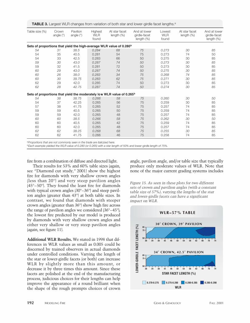
Back to Brilliance: The Effect on WLR of VaryingStar and Lower-Girdle Lengths. Recall that WLR val-ues are much smaller than DCLR values; a changein WLR of 0.005 is discernable to trained observers(Hemphill et al., 1998). We analyzed data for sets ofproportions (table size, crown angle, and pavilionangle) yielding high-average (0.280) and moderatelylow (0.265) WLR values when the star and lower-gir-dle facet lengths were at the reference proportions.Varying the length of the star or lower-girdle facetsfor these proportion combinations could increaseWLR by 0.007, or decrease it by 0.015 (table 3). Manymore proportion combinations led to decreases thanto increases. Commercially common round brilliantproportions (see box B) showed smaller changes inthe WLR value, whether increases or decreases, thanmore unusual proportions. The specific variations instar or lower-girdle facet length that produced thegreatest increase in WLR depended strongly on thecombination of crown angle, pavilion angle, and
table size. For a broad, commercial range of crownangles and pavilion angles, with smaller tables(53%–57%), longer star facet lengths producedincreases in WLR (see, e.g., figure 15).
DISCUSSIONDCLR and Proportions. Some proportion combina-tions that yield high DCLR values are not contiguousto one another, as shown in the contour plots(again, see figures 11–14). Thus, for some given val-ues of two proportions, changes in the third propor-tion in a single direction may produce lower andthen higher DCLR values. This variation in DCLRwith different proportion combinations prevents thesimple characterization of the “best” diamonds, interms of fire, by evaluation of individual proportionparameters. Rather, it is the interaction between theproportions of the pavilion (pavilion angle andlower-girdle facet length) and those of the crown(table size, crown angle, and star facet length) thatdetermines how light is dispersed by the round bril-liant. Although certain generalizations may bemade about the effects of a single proportion, inmost cases there exist combinations of proportionsthat compensate to change DCLR. For example,large tables generally produce low DCLR, but withsufficiently high crown angles and shallower pavil-ion angles, a round brilliant with a table as large as
DCLR
PAVI
LION
ANG
LE (d
egre
es)
CROWN ANGLE (degrees)
DCLR -- 50% STAR, 75% LOWER GIRDLEDCLR -- 50% STAR, 75% LOWER GIRDLE
66% TABLE66% TABLE60% TABLE60% TABLE54% TABLE54% TABLE
4.85-5.35
5.35-5.854.35-4.85
3.85-4.35
3.35-3.85
2.85-3.351.85-2.35
2.35-2.851.35-1.85
0.85-1.35
462810
44
42
38
36
40
16 22 34 40462810
44
42
38
36
40
16 22 34 40 462810
44
42
38
36
40
16 22 34 40
Figure 12. The possible combinations of crown angle and pavilion angle that yield above-average DCLR valuesgreatly decrease as table size increases. In addition, the specific crown and pavilion angles that produce above-average DCLR values change toward higher crown angle and lower pavilion angle as table size becomes very large.
66% can still yield an average or better DCLR value(see, e.g., diamond RD24 in table 2).
A short lower-girdle facet length of 50%, com-mon early in the 20th century, greatly decreasesDCLR and thus creates relatively poor fire (see, e.g.,figure 11). Because Marcel Tolkowsky also chosethis lower-girdle facet length, he made the reason-able—at that time—assumption that dispersionwithin the diamond could be neglected (see p. 56 ofhis 1919 treatise). Given the longer lower-girdlefacets cut today, however, such an omission resultsin a poor approximation of how light moves withina round brilliant diamond.
Recall that fire is the visible extent of light dis-persed into spectral colors. The type of lightingunder which a round brilliant cut diamond isobserved strongly affects the quantity and quality ofcolored light that emerges from it. With increasingdistance, this colored light can spread out over a
wide area; however, the eye can see only a fairlysmall area from one viewpoint. Thus, observation offire depends strongly on where the eye is relative tothe diamond, particularly how far away the observeris. Capturing all of the fire from the crown of a dia-mond required a multitude of observer positions, asif the diamond was being rocked. To achieve this,we used the same hemisphere of observations, andthe same position-dependent weights for observa-tions, for fire (DCLR) as we did for brilliance withthe WLR metric.
However, we used a very different lighting condi-tion for modeling fire than we used for modelingbrilliance. For actual diamonds, diffuse lightingbrings out brilliance and suppresses fire, while spotlighting does the opposite (again, see figure 1). Byexamining brilliance with fully diffuse light, and firewith a point source of light, we have explored themaximum extent to which the proportions of a
190 mODeLING FIRe GemS & GemOLOGy FALL 2001
DCLR
LOW
ER-G
IRDL
E FA
CET
LENG
TH (%
)
TABLE SIZE (%)
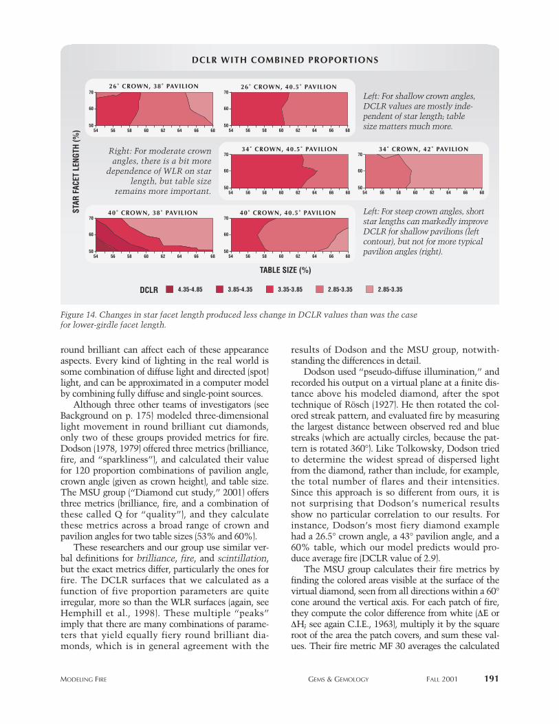
DCLR WITH COMBINED PROPORTIONSDCLR WITH COMBINED PROPORTIONS
3.85-4.35 3.35-3.85 2.85-3.35 2.35-2.85 1.85-2.35
26˚ CROWN, 38˚ PAVILION26˚ CROWN, 38˚ PAVILION85
50
75
34˚ CROWN, 42˚ PAVILION34˚ CROWN, 42˚ PAVILION85
50
75
26˚ CROWN, 40.5˚ PAVILION26˚ CROWN, 40.5˚ PAVILION85
50
75
40˚ CROWN, 38˚ PAVILION40˚ CROWN, 38˚ PAVILION85
50
75
34˚ CROWN, 40.5˚ PAVILION34˚ CROWN, 40.5˚ PAVILION85
50
75
40˚ CROWN, 40.5˚ PAVILION40˚ CROWN, 40.5˚ PAVILION85
50
75
686054 56 58 62 64 66 686054 56 58 62 64 66
686054 56 58 62 64 66686054 56 58 62 64 66
686054 56 58 62 64 66 686054 56 58 62 64 66
Figure 13. By grouping the contour plots, we can see how lower-girdle facet length, table size, and crown andpavilion angles work together to affect DCLR. Moderate to longer lower-girdle facet length generally increasesDCLR. This effect is most pronounced at moderate pavilion angles.
Left: For shallow crownangles, small tables haveaverage or higher DCLRvalues.
Left: For steep crown angles,still higher DCLR values areachievable with small tables,and DCLR is less sensitive tolower-girdle facet length.
Right: At moderatecrown angles, a wide
range of table sizes showaverage DCLR values.
mODeLING FIRe GemS & GemOLOGy FALL 2001 191
round brilliant can affect each of these appearanceaspects. Every kind of lighting in the real world issome combination of diffuse light and directed (spot)light, and can be approximated in a computer modelby combining fully diffuse and single-point sources.
Although three other teams of investigators (seeBackground on p. 175) modeled three-dimensionallight movement in round brilliant cut diamonds,only two of these groups provided metrics for fire.Dodson (1978, 1979) offered three metrics (brilliance,fire, and “sparkliness”), and calculated their valuefor 120 proportion combinations of pavilion angle,crown angle (given as crown height), and table size.The MSU group (“Diamond cut study,” 2001) offersthree metrics (brilliance, fire, and a combination ofthese called Q for “quality”), and they calculatethese metrics across a broad range of crown andpavilion angles for two table sizes (53% and 60%).
These researchers and our group use similar ver-bal definitions for brilliance, fire, and scintillation,but the exact metrics differ, particularly the ones forfire. The DCLR surfaces that we calculated as afunction of five proportion parameters are quiteirregular, more so than the WLR surfaces (again, seeHemphill et al., 1998). These multiple “peaks”imply that there are many combinations of parame-ters that yield equally fiery round brilliant dia-monds, which is in general agreement with the
results of Dodson and the MSU group, notwith-standing the differences in detail.
Dodson used “pseudo-diffuse illumination,” andrecorded his output on a virtual plane at a finite dis-tance above his modeled diamond, after the spottechnique of Rösch (1927). He then rotated the col-ored streak pattern, and evaluated fire by measuringthe largest distance between observed red and bluestreaks (which are actually circles, because the pat-tern is rotated 360°). Like Tolkowsky, Dodson triedto determine the widest spread of dispersed lightfrom the diamond, rather than include, for example,the total number of flares and their intensities.Since this approach is so different from ours, it isnot surprising that Dodson’s numerical resultsshow no particular correlation to our results. Forinstance, Dodson’s most fiery diamond examplehad a 26.5° crown angle, a 43° pavilion angle, and a60% table, which our model predicts would pro-duce average fire (DCLR value of 2.9).
The MSU group calculates their fire metrics byfinding the colored areas visible at the surface of thevirtual diamond, seen from all directions within a 60°cone around the vertical axis. For each patch of fire,they compute the color difference from white (ΔE orΔH; see again C.I.E., 1963), multiply it by the squareroot of the area the patch covers, and sum these val-ues. Their fire metric MF 30 averages the calculated
STAR
FAC
ET L
ENGT
H (%
)
TABLE SIZE (%)
DCLR WITH COMBINED PROPORTIONSDCLR WITH COMBINED PROPORTIONS
4.35-4.85 3.85-4.35 3.35-3.85 2.85-3.35 2.85-3.35
26˚ CROWN , 38˚ PAV ILION26˚ CROWN , 38˚ PAV ILION70
50
60
686054 56 58 62 64 66
26˚ CROWN , 40.5 ˚ PAV ILION26˚ CROWN , 40.5 ˚ PAV ILION70
50
60
686054 56 58 62 64 66
34 ˚ CROWN , 40.5 ˚ PAV ILION34 ˚ CROWN , 40.5 ˚ PAV ILION70
50
60
686054 56 58 62 64 66
40 ˚ CROWN , 38˚ PAV ILION40 ˚ CROWN , 38˚ PAV ILION70
50
60
686054 56 58 62 64 66
40 ˚ CROWN , 40.5 ˚ PAV ILION40 ˚ CROWN , 40.5 ˚ PAV ILION70
50
60
686054 56 58 62 64 66
CROWN ANGLE
34 ˚ CROWN , 42˚ PAV ILION34 ˚ CROWN , 42˚ PAV ILION70
50
60
686054 56 58 62 64 66
DCLR
Figure 14. Changes in star facet length produced less change in DCLR values than was the casefor lower-girdle facet length.
Left: For shallow crown angles,DCLR values are mostly inde-pendent of star length; tablesize matters much more.
Left: For steep crown angles, shortstar lengths can markedly improveDCLR for shallow pavilions (leftcontour), but not for more typicalpavilion angles (right).
Right: For moderate crownangles, there is a bit more
dependence of WLR on starlength, but table size
remains more important.
fire from a combination of diffuse and directed light.Their results for 53% and 60% table sizes (again,
see “Diamond cut study,” 2001) show the highestfire for diamonds with very shallow crown angles(less than 20°) and very steep pavilion angles(45°–50°). They found the least fire for diamondswith typical crown angles (30°–36°) and steep pavil-ion angles (greater than 43°) at both table sizes. Incontrast, we found that diamonds with steepercrown angles (greater than 36°) show high fire acrossthe range of pavilion angles we considered (36°–45°);the lowest fire predicted by our model is producedby diamonds with very shallow crown angles andeither very shallow or very steep pavilion angles(again, see figure 11).
Additional WLR Results. We stated in 1998 that dif-ferences in WLR values as small as 0.005 could bediscerned by trained observers in actual diamondsunder controlled conditions. Varying the length ofthe star or lower-girdle facets (or both) can increaseWLR by slightly more than this amount, ordecrease it by three times this amount. Since thesefacets are polished at the end of the manufacturingprocess, judicious choices for their lengths can helpimprove the appearance of a round brilliant whenthe shape of the rough prompts choices of crown
angle, pavilion angle, and/or table size that typicallyproduce only moderate values of WLR. Note thatnone of the major current grading systems includes
192 mODeLING FIRe GemS & GemOLOGy FALL 2001
TABLE 3. Largest WLR changes from variation of both star and lower-girdle facet lengths.a
Table size (%) Crown Pavilion Highest At star facet And at lower Lowest At star facet And at lowerangle (°) angle (°) WLR length (%) girdle-facet WLR length (%) girdle-facet
found length (%) found length (%)
Sets of proportions that yield the high-average WLR value of 0.280b
54 31 38.5 0.284 68 75 0.273 30 8554 35 40.5 0.281 54 75 0.273 74 5054 33 42.5 0.283 66 50 0.275 30 8559 30 43.0 0.287 74 50 0.273 30 8559 32 41.5 0.281 72 50 0.273 30 8560 29 43.0 0.287 74 50 0.275 30 8560 26 38.0 0.283 34 75 0.268 74 8560 30 39.75 0.283 62 75 0.271 30 8562 29 42.0 0.285 74 50 0.273 30 8562 28 42.75 0.287 74 50 0.274 30 85
Sets of proportions that yield the moderately low WLR value of 0.265b
54 38 38.75 0.266 58 75 0.260 30 5054 37 42.25 0.265 56 75 0.259 30 8557 38 41.75 0.265 52 75 0.257 74 8559 59 40.5 0.265 50 75 0.259 74 8559 59 42.0 0.265 48 75 0.257 74 8560 60 38.5 0.266 58 75 0.262 30 5060 60 40.5 0.265 42 75 0.259 74 8560 60 42.0 0.265 48 75 0.257 74 8562 62 38.25 0.268 68 75 0.255 30 8562 62 41.75 0.266 46 75 0.258 74 85
aProportions that are not commonly seen in the trade are italicized here.bEach example yielded the WLR value of 0.280 (or 0.265) with a star length of 50% and lower-girdle length of 75%.
0.285-0.2900.280-0.2850.275-0.2800.270-0.275
WLR
LOW
ER-G
IRDL
E F
ACET
LEN
GTH
(%)
STAR FACET LENGTH (%)
705030
85
75
50
30˚ CROWN, 39˚ PAVILION30˚ CROWN, 39˚ PAVILION
34 38 42 46 54 58 62 66 74
34˚ CROWN, 42.5˚ PAVILION34˚ CROWN, 42.5˚ PAVILION
705030
8575
5034 38 42 46 54 58 62 66 74
WLR--57% TABLEWLR--57% TABLE
Figure 15. As seen in these plots for two differentsets of crown and pavilion angles (with a constanttable size of 57%), varying the lengths of the starand lower-girdle facets can have a significantimpact on WLR.
mODeLING FIRe GemS & GemOLOGy FALL 2001 193
the length of star or lower-girdle facets in their anal-ysis of cut.
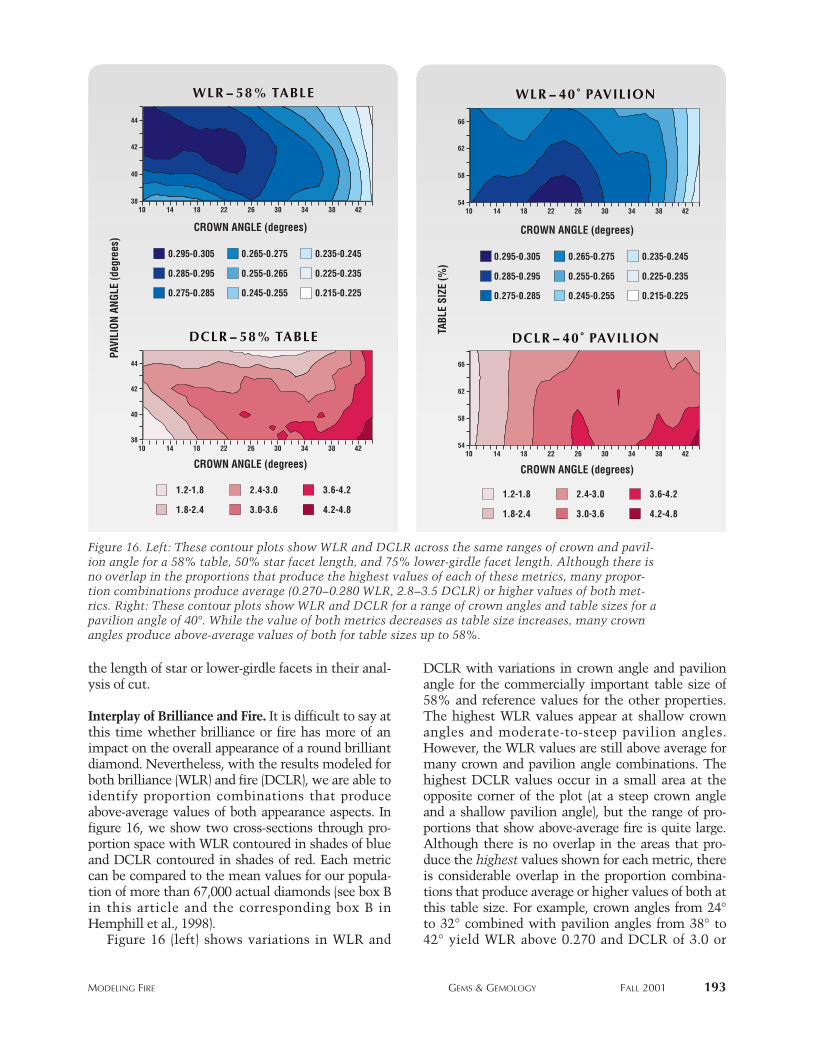
Interplay of Brilliance and Fire. It is difficult to say atthis time whether brilliance or fire has more of animpact on the overall appearance of a round brilliantdiamond. Nevertheless, with the results modeled forboth brilliance (WLR) and fire (DCLR), we are able toidentify proportion combinations that produceabove-average values of both appearance aspects. Infigure 16, we show two cross-sections through pro-portion space with WLR contoured in shades of blueand DCLR contoured in shades of red. Each metriccan be compared to the mean values for our popula-tion of more than 67,000 actual diamonds (see box Bin this article and the corresponding box B inHemphill et al., 1998).
Figure 16 (left) shows variations in WLR and
DCLR with variations in crown angle and pavilionangle for the commercially important table size of58% and reference values for the other properties.The highest WLR values appear at shallow crownangles and moderate-to-steep pavilion angles.However, the WLR values are still above average formany crown and pavilion angle combinations. Thehighest DCLR values occur in a small area at theopposite corner of the plot (at a steep crown angleand a shallow pavilion angle), but the range of pro-portions that show above-average fire is quite large.Although there is no overlap in the areas that pro-duce the highest values shown for each metric, thereis considerable overlap in the proportion combina-tions that produce average or higher values of both atthis table size. For example, crown angles from 24°to 32° combined with pavilion angles from 38° to42° yield WLR above 0.270 and DCLR of 3.0 or
PAVI
LION
ANG
LE (d
egre
es)
CROWN ANGLE (degrees)
WLR -- 58% TABLEWLR -- 58% TABLE
DCLR -- 58% TABLEDCLR -- 58% TABLE
3010
40
3814 18 22 26 34 38 42
42
44
3010 14 18 22 26 34 38 42
40
38
42
44
0.235-0.2450.265-0.2750.295-0.305
0.225-0.2350.255-0.2650.285-0.295
0.215-0.2250.245-0.2550.275-0.285
3.6-4.22.4-3.01.2-1.8
4.2-4.83.0-3.61.8-2.4
CROWN ANGLE (degrees)
TABL
E SI
ZE (%
)
CROWN ANGLE (degrees)
WLR -- 40˚ PAVILIONWLR -- 40˚ PAVILION
DCLR -- 40˚ PAVILIONDCLR -- 40˚ PAVILION
0.235-0.2450.265-0.2750.295-0.305
0.225-0.2350.255-0.2650.285-0.295
0.215-0.2250.245-0.2550.275-0.285
3.6-4.22.4-3.01.2-1.8
4.2-4.83.0-3.61.8-2.4
CROWN ANGLE (degrees)
3010 14 18 22 26 34 38 42
3010
58
5414 18 22 26 34 38 42
62
66
58
54
62
66
Figure 16. Left: These contour plots show WLR and DCLR across the same ranges of crown and pavil-ion angle for a 58% table, 50% star facet length, and 75% lower-girdle facet length. Although there isno overlap in the proportions that produce the highest values of each of these metrics, many propor-tion combinations produce average (0.270–0.280 WLR, 2.8–3.5 DCLR) or higher values of both met-rics. Right: These contour plots show WLR and DCLR for a range of crown angles and table sizes for apavilion angle of 40°. While the value of both metrics decreases as table size increases, many crownangles produce above-average values of both for table sizes up to 58%.
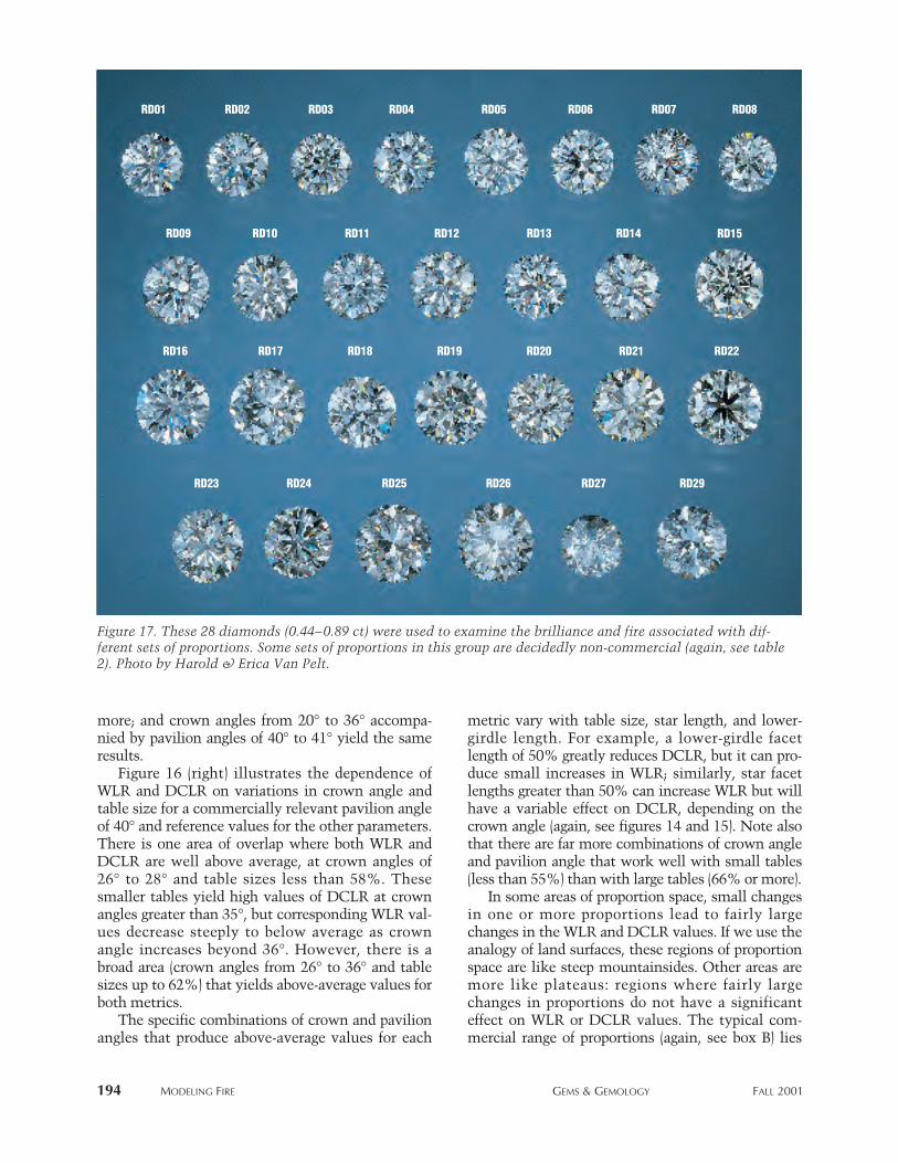
more; and crown angles from 20° to 36° accompa-nied by pavilion angles of 40° to 41° yield the sameresults.
Figure 16 (right) illustrates the dependence ofWLR and DCLR on variations in crown angle andtable size for a commercially relevant pavilion angleof 40° and reference values for the other parameters.There is one area of overlap where both WLR andDCLR are well above average, at crown angles of26° to 28° and table sizes less than 58%. Thesesmaller tables yield high values of DCLR at crownangles greater than 35°, but corresponding WLR val-ues decrease steeply to below average as crownangle increases beyond 36°. However, there is abroad area (crown angles from 26° to 36° and tablesizes up to 62%) that yields above-average values forboth metrics.
The specific combinations of crown and pavilionangles that produce above-average values for each
metric vary with table size, star length, and lower-girdle length. For example, a lower-girdle facetlength of 50% greatly reduces DCLR, but it can pro-duce small increases in WLR; similarly, star facetlengths greater than 50% can increase WLR but willhave a variable effect on DCLR, depending on thecrown angle (again, see figures 14 and 15). Note alsothat there are far more combinations of crown angleand pavilion angle that work well with small tables(less than 55%) than with large tables (66% or more).
In some areas of proportion space, small changesin one or more proportions lead to fairly largechanges in the WLR and DCLR values. If we use theanalogy of land surfaces, these regions of proportionspace are like steep mountainsides. Other areas aremore like plateaus: regions where fairly largechanges in proportions do not have a significanteffect on WLR or DCLR values. The typical com-mercial range of proportions (again, see box B) lies
194 mODeLING FIRe GemS & GemOLOGy FALL 2001
Figure 17. These 28 diamonds (0.44–0.89 ct) were used to examine the brilliance and fire associated with dif-ferent sets of proportions. Some sets of proportions in this group are decidedly non-commercial (again, see table2). Photo by Harold & Erica Van Pelt.
RD01 RD02 RD03 RD04 RD05 RD06 RD07 RD08
RD09 RD10 RD11 RD12 RD13 RD14 RD15
RD16 RD17 RD18 RD19 RD20 RD21 RD22
RD23 RD24 RD25 RD26 RD27 RD29
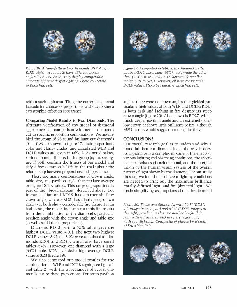
mODeLING FIRe GemS & GemOLOGy FALL 2001 195
within such a plateau. Thus, the cutter has a broadlatitude for choices of proportions without risking acatastrophic effect on appearance.
Comparing Model Results to Real Diamonds. Theultimate verification of any model of diamondappearance is a comparison with actual diamondscut to specific proportion combinations. We assem-bled the group of 28 round brilliant cut diamonds(0.44–0.89 ct) shown in figure 17; their proportions,color and clarity grades, and calculated WLR andDCLR values are given in table 2. As noted below,various round brilliants in this group (again, see fig-ure 1) both confirm the fitness of our model anddefy a few common beliefs in the trade about therelationship between proportions and appearance.
There are many combinations of crown angle,table size, and pavilion angle that produce averageor higher DCLR values. This range of proportions ispart of the “broad plateau” described above. Forinstance, diamond RD19 has a rather shallowcrown angle, whereas RD21 has a fairly steep crownangle; yet both show considerable fire (figure 18). Inboth cases, the model indicates that this fire resultsfrom the combination of the diamond’s particularpavilion angle with the crown angle and table size(as well as additional proportions).
Diamond RD13, with a 52% table, gave thehighest DCLR value (4.01). The next two highestDCLR values (3.97 and 3.92) were calculated for dia-monds RD01 and RD23, which also have smalltables (54%). However, one diamond with a large(66%) table, RD24, yielded a high average DCLRvalue of 3.23 (figure 19).
We also compared our model results for thecombination of WLR and DCLR (again, see figure 1and table 2) with the appearances of actual dia-monds cut to these proportions. For steep pavilion
angles, there were no crown angles that yielded par-ticularly high values of both WLR and DCLR; RD25is both dark and lacking in fire despite its steepcrown angle (figure 20). Also shown is RD27, with amuch deeper pavilion angle and an extremely shal-low crown; it shows little brilliance or fire (althoughMSU results would suggest it to be quite fiery).
CONCLUSIONSOur overall research goal is to understand why around brilliant cut diamond looks the way it does.Its appearance is a complex mixture of the effects ofvarious lighting and observing conditions, the specif-ic characteristics of each diamond, and the interpre-tation by the human visual system of the overallpattern of light shown by the diamond. For our studythus far, we found that different lighting conditionsare needed to bring out the maximum brilliance(totally diffused light) and fire (directed light). Wemade simplifying assumptions about the diamond
Figure 18. Although these two diamonds (RD19, left;RD21, right—see table 2) have different crownangles (29.2° and 35.8°), they display comparableamounts of fire with spot lighting. Photo by Harold& Erica Van Pelt.
Figure 19. As reported in table 2, the diamond on thefar left (RD24) has a large (66%), table while the otherthree (RD01, RD23, and RD13) have much smallertables (52% to 54%). However, all have comparableDCLR values. Photo by Harold & Erica Van Pelt.
Figure 20. These two diamonds, with 50.7° (RD27,left image in each pair) and 41.8° (RD25, images atthe right) pavilion angles, are neither bright (leftpair, with diffuse lighting) nor fiery (right pair,with spot lighting). Composite of photos by Harold& Erica Van Pelt.
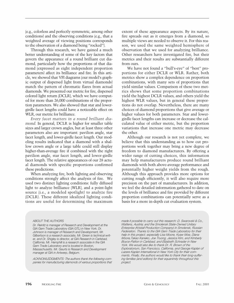
(e.g., colorless and perfectly symmetric, among otherconditions) and the observing conditions (e.g., that aweighted average of viewing positions correspondsto the observation of a diamond being “rocked”).
Through this research, we have gained a muchbetter understanding of some of the key factors thatgovern the appearance of a round brilliant cut dia-mond, particularly how the proportions of that dia-mond (expressed as eight independent proportionparameters) affect its brilliance and fire. In this arti-cle, we showed that VFI diagrams (our model’s graph-ic output of dispersed light from virtual diamonds)match the pattern of chromatic flares from actualdiamonds. We presented our metric for fire, dispersedcolored light return (DCLR), which we have comput-ed for more than 26,000 combinations of the propor-tion parameters. We also showed that star and lower-girdle facet lengths could have a noticeable effect onWLR, our metric for brilliance.
Every facet matters in a round brilliant dia-mond. In general, DCLR is higher for smaller tablesizes and larger crown angles, but at least three otherparameters also are important: pavilion angle, starfacet length, and lower-girdle facet length. Our mod-eling results indicated that a diamond with a shal-low crown angle or a large table could still displayhigher-than-average fire if combined with the rightpavilion angle, star facet length, and lower-girdlefacet length. The relative appearances of our 28 actu-al diamonds with specific proportions confirmedthese predictions.
When analyzing fire, both lighting and observingconditions strongly affect the analysis of fire. Weused two distinct lighting conditions: fully diffusedlight to analyze brilliance (WLR), and a point-lightsource (i.e., a modeled spotlight) to analyze fire(DCLR). These different idealized lighting condi-tions are useful for determining the maximum
extent of these appearance aspects. By its nature,fire spreads out as it emerges from a diamond, somultiple views are needed to observe it. For this rea-son, we used the same weighted hemisphere ofobservation that we used for analyzing brilliance.Other researchers have investigated fire, but theirmetrics and their results are substantially differentfrom ours.
We have not found a “bull’s-eye” of “best” pro-portions for either DCLR or WLR. Rather, bothmetrics show a complex dependence on proportioncombinations, with many sets of proportions thatyield similar values. Comparison of these two met-rics shows that some proportion combinationsyield the highest DCLR values, and others yield thehighest WLR values, but in general these propor-tions do not overlap. Nevertheless, there are manychoices of diamond proportions that give average orhigher values for both parameters. Star and lower-girdle facet lengths can increase or decrease the cal-culated value of either metric, but the proportionvariations that increase one metric may decreasethe other.
Although our research is not yet complete, webelieve that this understanding as to how cut pro-portions work together may bring a new degree offreedom to diamond manufacturers. By offering awider range of cutting choices, this informationmay help manufacturers produce round brilliantdiamonds with both above-average performance andpotentially higher weight yields from the rough.Although this approach provides more options forcutting rough efficiently, it will also require moreprecision on the part of manufacturers. In addition,we feel the detailed information gathered to date onthe levels of brilliance and fire provided by differentproportion combinations can potentially serve as abasis for a more in-depth cut evaluation system.
196 mODeLING FIRe GemS & GemOLOGy FALL 2001
ABOUT THE AUTHORSDr. Reinitz is manager of Research and Development at theGIA Gem Trade Laboratory (GIA GTL) in New York. Dr.Johnson is manager of Research and Development, Mr.Gilbertson is a research associate, Mr. Green is technical writ-er, and Dr. Shigley is director, at GIA Research in Carlsbad,California. Mr. Hemphill is a research associate in the GIAGem Trade Laboratory and is located in Boston,Massachusetts. Mr. Geurts is Research and Developmentmanager at GIA in Antwerp, Belgium.
ACKNOWLEDGMENTS: The authors thank the following com-panies for manufacturing diamonds of various proportions that
made it possible to carry out this research: D. Swarovski & Co.,Wattens, Austria; and the Smolensk State-Owned UnitaryEnterprise (Kristall Production Company) in Smolensk, RussianFederation. Thanks to the GIA Gem Trade Laboratory for theirhelp in this project, especially Lisa Moore, Kyaw Moe, DianaMoore,Takao Kaneko, Joe Truong, Jessica Kim, and KimberlyBoyce-Patton in Carlsbad, and Elizabeth Schrader in NewYork. We would also like to thank Dr. R. Brown of theExploratorium, San Francisco, California, and George Kaplan ofLazare Kaplan International in New York City for their com-ments. Finally, the authors would like to thank their long-suffer-ing families (and editors) for their equanimity throughout thisproject.
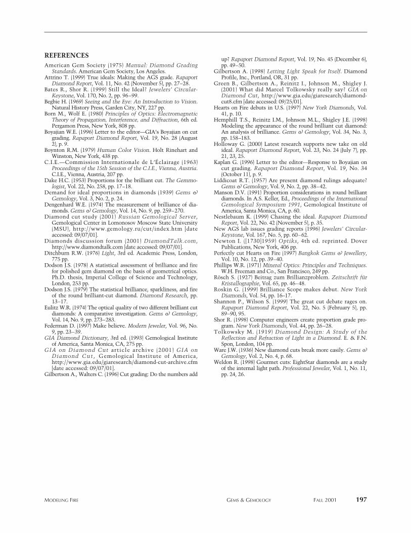
mODeLING FIRe GemS & GemOLOGy FALL 2001 197
REFERENCESAmerican Gem Society (1975) Manual: Diamond Grading
Standards. American Gem Society, Los Angeles.Attrino T. (1999) True ideals: Making the AGS grade. Rapaport
Diamond Report, Vol. 11, No. 42 (November 5), pp. 27–28.Bates R., Shor R. (1999) Still the Ideal? Jewelers’ Circular-
Keystone, Vol. 170, No. 2, pp. 96–99.Begbie H. (1969) Seeing and the Eye: An Introduction to Vision.
Natural History Press, Garden City, NY, 227 pp.Born M., Wolf E. (1980) Principles of Optics: Electromagnetic
Theory of Propagation, Interference, and Diffraction, 6th ed.Pergamon Press, New York, 808 pp.
Boyajian W.E. (1996) Letter to the editor—GIA’s Boyajian on cutgrading. Rapaport Diamond Report, Vol. 19, No. 28 (August2), p. 9.
Boynton R.M. (1979) Human Color Vision. Holt Rinehart andWinston, New York, 438 pp.
C.I.E.—Commission Internationale de L’Éclairage (1963)Proceedings of the 15th Session of the C.I.E., Vienna, Austria.C.I.E., Vienna, Austria, 207 pp.
Dake H.C. (1953) Proportions for the brilliant cut. The Gemmo -lo gist, Vol. 22, No. 258, pp. 17–18.
Demand for ideal proportions in diamonds (1939) Gems &Gemology, Vol. 3, No. 2, p. 24.
Dengenhard W.E. (1974) The measurement of brilliance of dia-monds. Gems & Gemology, Vol. 14, No. 9, pp. 259–270.
Diamond cut study (2001) Russian Gemological Server,Gemological Center in Lomonosov Moscow State University(MSU), http://www.gemology.ru/cut/index.htm [dateaccessed: 09/07/01].
Diamonds discussion forum (2001) DiamondTalk.com,http://www.diamondtalk.com [date accessed: 09/07/01].
Ditchburn R.W. (1976) Light, 3rd ed. Academic Press, London,775 pp.
Dodson J.S. (1978) A statistical assessment of brilliance and firefor polished gem diamond on the basis of geometrical optics.Ph.D. thesis, Imperial College of Science and Technology,London, 253 pp.
Dodson J.S. (1979) The statistical brilliance, sparkliness, and fireof the round brilliant-cut diamond. Diamond Research, pp.13–17.
Eulitz W.R. (1974) The optical quality of two different brilliant cutdiamonds: A comparative investigation. Gems & Gemology,Vol. 14, No. 9, pp. 273–283.
Federman D. (1997) Make believe. Modern Jeweler, Vol. 96, No.9, pp. 23–39.
GIA Diamond Dictionary, 3rd ed. (1993) Gemological Instituteof America, Santa Monica, CA, 275 pp.
GIA on Diamond Cut article archive (2001) GIA onDiamond Cut , Gemological Institute of America,http://www.gia.edu/giaresearch/diamond-cut-archive.cfm[date accessed: 09/07/01].
Gilbertson A., Walters C. (1996) Cut grading: Do the numbers add
up? Rapaport Diamond Report, Vol. 19, No. 45 (December 6),pp. 49–50.
Gilbertson A. (1998) Letting Light Speak for Itself. DiamondProfile, Inc., Portland, OR, 31 pp.
Green B., Gilbertson A., Reinitz I., Johnson M., Shigley J.(2001) What did Marcel Tolkowsky really say? GIA onDiamond Cut, http://www.gia.edu/giaresearch/diamond-cut8.cfm [date accessed: 09/25/01].
Hearts on Fire debuts in U.S. (1997) New York Diamonds, Vol.41, p. 10.
Hemphill T.S., Reinitz I.M., Johnson M.L., Shigley J.E. (1998)Modeling the appearance of the round brilliant cut diamond:An analysis of brilliance. Gems & Gemology, Vol. 34, No. 3,pp. 158–183.
Holloway G. (2000) Latest research supports new take on oldideal. Rapaport Diamond Report, Vol. 23, No. 24 (July 7), pp.21, 23, 25.
Kaplan G. (1996) Letter to the editor—Response to Boyajian oncut grading. Rapaport Diamond Report, Vol. 19, No. 34(October 11), p. 9.
Liddicoat R.T. (1957) Are present diamond rulings adequate?Gems & Gemology, Vol. 9, No. 2, pp. 38–42.
Manson D.V. (1991) Proportion considerations in round brilliantdiamonds. In A.S. Keller, Ed., Proceedings of the InternationalGemological Symposium 1991, Gemological Institute ofAmerica, Santa Monica, CA, p. 60.
Nestlebaum K. (1999) Chasing the ideal. Rapaport DiamondReport, Vol. 22, No. 42 (November 5), p. 35.
New AGS lab issues grading reports (1996) Jewelers’ Circular-Keystone, Vol. 167, No. 5, pp. 60–62.
Newton I. ([1730]1959) Optiks, 4th ed. reprinted. DoverPublications, New York, 406 pp.
Perfectly cut Hearts on Fire (1997) Bangkok Gems & Jewellery,Vol. 10, No. 12, pp. 39–40.
Phillips W.R. (1971) Mineral Optics: Principles and Techniques.W.H. Freeman and Co., San Francisco, 249 pp.
Rösch S. (1927) Beitrag zum Brillianzproblem. Zeitschrift fürKristallographie, Vol. 65, pp. 46–48.
Roskin G. (1999) Brilliance Scope makes debut. New YorkDiamonds, Vol. 54, pp. 16–17.
Shannon P., Wilson S. (1999) The great cut debate rages on.Rapaport Diamond Report, Vol. 22, No. 5 (February 5), pp.89–90, 95.
Shor R. (1998) Computer engineers create proportion grade pro-gram. New York Diamonds, Vol. 44, pp. 26–28.
Tolkowsky M. (1919) Diamond Design: A Study of theReflection and Refraction of Light in a Diamond. E. & F.N.Spon, London, 104 pp.
Ware J.W. (1936) New diamond cuts break more easily. Gems &Gemology, Vol. 2, No. 4, p. 68.
Weldon R. (1998) Gourmet cuts: EightStar diamonds are a studyof the internal light path. Professional Jeweler, Vol. 1, No. 11,pp. 24, 26.
PYROPE FROM THEDORA MAIRA MASSIF, ITALY
198 NOTES AND NEW TECHNIQUES GEMS & GEMOLOGY FALL 2001
LOCATION AND ACCESSThe Dora Maira Massif is located in the Piedmontregion, 50 km (31 miles) southwest of Turin (figure2). Pyrope is found in the Varaita Valley, betweenthe villages of Brossasco and Martiniana Po. Gempyropes have been collected in several outcrops overan extended area (about 15 km long) from high-grade quartz-phengitic metamorphic rocks. Large-scale mining is forbidden by environmental policy,but local collectors do considerable hand digging.
GEOLOGIC SETTINGThe Dora Maira Massif consists of Paleozoic base-ment rocks with an overlying Mesozoic series ofrocks that are characterized by an Alpine high-pres-sure/low-temperature metamorphic overprint. Thepyrope crystals occur in a light-colored phengiticschist-quartzite layer, measuring a few metersthick, which was referred to as “micascisti splen-denti” by Stella (1895) and Franchi (1900). Thequartzite layer contains large flakes of phengite (ahigh-pressure mica; Mandarino, 1999) and pale pur-plish pink pyrope crystals that reach 25 cm in diam-eter. Vialon (1966) mapped the quartzite layer over adistance of about 15 km, and suggested that the pro-tolith (original unmetamorphosed rock) was a leu-cocratic granitic vein that was strongly deformed bymetamorphism. Other rocks in the area includefine-grained felsic paragneisses that are associatedwith lenses of marble and metabasite. In describing
By Alessandro Guastoni, Federico Pezzotta, Margherita Superchi, and Francesco Demartin
See end of article for author information and acknowledgments.GEMS & GEMOLOGY, Vol. 37, No. 3, pp. 198–204© 2001 Gemological Institute of America
or several years, large pyrope crystals havebeen known from the Varaita Valley in theDora Maira Massif (a massive topographic and
structural feature, particularly within a mountainrange) in Italy’s Western Alps (Schert et al., 1994).Since the early 1990s, local mineral collectors haverecovered and cut crystals containing gem-qualityportions. Although the gemstones have rarelyexceeded 1 ct (the largest known to date are about 2ct), a few hundred good-quality faceted Dora Mairapyropes have entered the Italian gem collector’smarket. The distinctive features of these gempyropes are their pale purplish pink color (figure 1),near-end-member composition, and mineral inclu-sions. Of particular interest are inclusions of ellen-bergerite, for which Dora Maira is the type locality.
NOTES & NEW TECHNIQUES
F
Large pyrope crystals containing gem-quality por-tions have been collected since the early 1990s fromthe Dora Maira Massif, Western Alps, Italy. Thesecrystals have yielded pale purple to purplish pinkgemstones typically up to 1 ct. The chemical com-position and physical properties compare favorablyto those reported for near-end-member pyrope.Absorption spectra suggest that the color is related toFe2+ and Mn2+. The pyrope formed in a mica schist-quartzite layer within Paleozoic basement rocks thatunderwent an Alpine high-pressure/low-temperaturemetamorphic event. The deposit appears extensive,but future production undoubtedly will be limiteddue to environmental restraints. Currently about 100carats per year enter the marketplace.
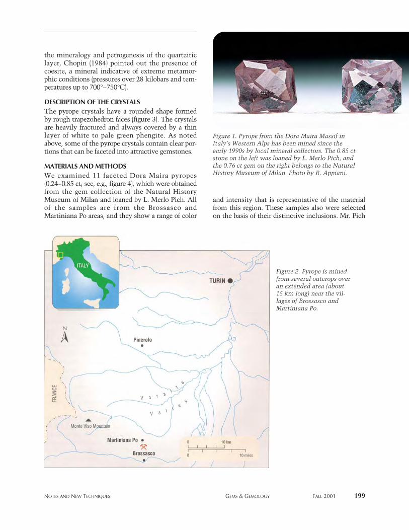
NOTES AND NEW TECHNIQUES GEMS & GEMOLOGY FALL 2001 199
the mineralogy and petrogenesis of the quartziticlayer, Chopin (1984) pointed out the presence ofcoesite, a mineral indicative of extreme metamor-phic conditions (pressures over 28 kilobars and tem-peratures up to 700°–750°C).
DESCRIPTION OF THE CRYSTALSThe pyrope crystals have a rounded shape formedby rough trapezohedron faces (figure 3). The crystalsare heavily fractured and always covered by a thinlayer of white to pale green phengite. As notedabove, some of the pyrope crystals contain clear por-tions that can be faceted into attractive gemstones.
MATERIALS AND METHODSWe examined 11 faceted Dora Maira pyropes(0.24–0.85 ct; see, e.g., figure 4), which were obtainedfrom the gem collection of the Natural HistoryMuseum of Milan and loaned by L. Merlo Pich. Allof the samples are from the Brossasco andMartiniana Po areas, and they show a range of color
and intensity that is representative of the materialfrom this region. These samples also were selectedon the basis of their distinctive inclusions. Mr. Pich
Figure 2. Pyrope is minedfrom several outcrops overan extended area (about15 km long) near the vil-lages of Brossasco andMartiniana Po.
Figure 1. Pyrope from the Dora Maira Massif inItaly’s Western Alps has been mined since theearly 1990s by local mineral collectors. The 0.85 ctstone on the left was loaned by L. Merlo Pich, andthe 0.76 ct gem on the right belongs to the NaturalHistory Museum of Milan. Photo by R. Appiani.
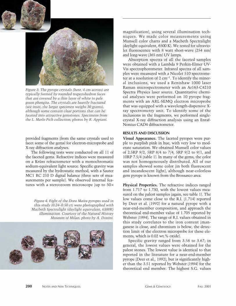
200 NOTES AND NEW TECHNIQUES GEMS & GEMOLOGY FALL 2001
provided fragments (from the same crystals used tofacet some of the gems) for electron-microprobe andX-ray diffraction analyses.
The following tests were conducted on all 11 ofthe faceted gems. Refractive indices were measuredon a Krüss refractometer with a monochromaticsodium-equivalent light source. Specific gravity wasmeasured by the hydrostatic method, with a SauterMC1 RC 210 D digital balance (three sets of mea-surements per sample). We observed internal fea-tures with a stereozoom microscope (up to 50¥
magnification), using several illumination tech-niques. We made color measurements usingMunsell color charts and a Macbeth Spectralight(daylight equivalent, 6500 K). We tested for ultravio-let fluorescence with 8 watt short-wave (254 nm)and long-wave (365 nm) UV lamps.
Absorption spectra of all the faceted sampleswere obtained with a Lambda 9 Perkin-Elmer UV-Vis spectrophotometer. Infrared spectra of all sam-ples were measured with a Nicolet 510 spectrome-ter at a resolution of 2 cm-1. To identify the miner-al inclusions, we used a Renishaw 1000 laserRaman microspectrometer with an Ar163-C4210Spectra Physics laser source. Quantitative chemi-cal analyses were performed on 10 pyrope frag-ments with an ARL-SEMQ electron microprobethat was equipped with a wavelength-dispersive X-ray spectrometry unit. To identify some of theinclusions in the fragments, we performed single-crystal X-ray diffraction analysis using an Enraf-Nonius CAD4 diffractometer.
RESULTS AND DISCUSSIONVisual Appearance. The faceted pyropes were pur-ple to purplish pink in hue, with very low to mod-erate saturation. We obtained Munsell color valuesof 2.5RP 9/2, 5RP 8/4 to 7/4, 5RP 9/2 to 9/1, and10RP 7.5/4 (table 1). In many of the gems, the colorwas not homogeneously distributed. All of oursamples showed some color (in both fluorescentand incandescent light), although near-colorlessgem pyrope is known from the Brossasco area.
Physical Properties. The refractive indices rangedfrom 1.717 to 1.730, with the lowest values mea-sured on the palest samples (again, see table 1). Thelow values come close to the R.I. (1.714) reportedby Deer et al. (1992) for a natural pyrope with anear-end-member composition, and approach thetheoretical end-member value of 1.705 reported byWebster (1994). The range of R.I. values obtained inthis study correlates to the iron content (man-ganese is close, and chromium is below, the detec-tion limit of the electron microprobe for these ele-ments, which is 0.02 wt.% oxide).
Specific gravity ranged from 3.58 to 3.67; ingeneral, the lowest values were obtained for thepalest stones. The lowest value is identical to thatreported in the literature for a near-end-memberpyrope (Deer et al., 1992), but is significantly high-er than the 3.51 reported by Webster (1994) for thetheoretical end member. The highest S.G. values
Figure 4. Eight of the Dora Maira pyropes used inthis study (0.24–0.50 ct) were photographed with
Macbeth Spectralight (daylight equivalent, 6500K)illumination. Courtesy of the Natural History
Museum of Milan; photo by A. Donini.
Figure 3. The pyrope crystals (here, 4 cm across) aretypically formed by rounded trapezohedron facesthat are covered by a thin layer of white to palegreen phengite. The crystals are heavily fractured(see inset; the larger specimen weighs 30 grams),although some contain clear portions that can befaceted into attractive gemstones. Specimens fromthe L. Merlo Pich collection; photos by R. Appiani.
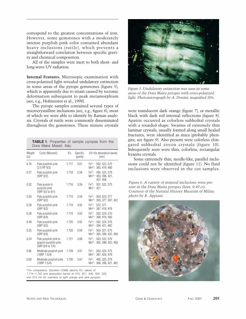
NOTES AND NEW TECHNIQUES GEMS & GEMOLOGY FALL 2001 201
correspond to the greatest concentrations of iron.However, some gemstones with a moderatelyintense purplish pink color contained abundantheavy inclusions (rutile), which prevents astraightforward correlation between specific gravi-ty and chemical composition.
All of the samples were inert to both short- andlong-wave UV radiation.
Internal Features. Microsopic examination withcross-polarized light revealed undulatory extinctionin some areas of the pyrope gemstones (figure 5),which is apparently due to strain caused by tectonicdeformation subsequent to peak metamorphism(see, e.g., Hofmeister et al., 1998).
The pyrope samples contained several types ofmicrocrystalline inclusions (see, e.g., figure 6), mostof which we were able to identify by Raman analy-sis. Crystals of rutile were commonly disseminatedthroughout the gemstones. These minute crystals
were translucent dark orange (figure 7), or metallicblack with dark red internal reflections (figure 8).Apatite occurred as colorless subhedral crystalswith a rounded shape. Swarms of extremely thinlaminar crystals, usually formed along small healedfractures, were identified as mica (probably phen-gite; see figure 9). Also present were colorless elon-gated subhedral zircon crystals (figure 10).Infrequently seen were thin, colorless, rectangularkyanite crystals.
Some extremely thin, needle-like, parallel inclu-sions could not be identified (figure 11). No fluidinclusions were observed in the cut samples.
Figure 5. Undulatory extinction was seen in someareas of the Dora Maira pyropes with cross-polarizedlight. Photomicrograph by A. Donini; magnified 50¥.
TABLE 1. Properties of sample pyropes from theDora Maira Massif, Italy.
Weight Color (Munsell) R.I. Specific UV-Vis absorption bands(ct) gravity (nm)
0.76 Pale purplish pink 1.717 3.61 Fe2+: 502, 522, 575(2.5 RP 9/2) Mn2+: 365, 419, 460
0.27 Pale purplish pink 1.718 3.58 Fe2+: 495, 525, 579(5RP 9/2) Mn2+: 363, 396, 421,
437, 4580.32 Pale purple to 1.718 3.59 Fe2+: 501, 522, 575
purplish pink Mn2+: 421(5RP 9/2 to 9/1)
0.50 Pale purplish pink 1.719 3.59 Fe2+: 503, 523, 577(5RP 9/2) Mn2+: 365, 377, 397, 422
0.26 Pale purplish pink 1.719 3.62 Fe2+: 522, 577(5RP 9/2) Mn2+: 367, 419, 479
0.28 Pale purplish pink 1.719 3.63 Fe2+: 502, 524, 575(5RP 8/4) Mn2+: 366, 419, 460
0.49 Pale purplish pink 1.720 3.62 Fe2+: 502, 524, 576(5RP 9/2) Mn2+: 394, 421, 462
0.25 Pale purplish pink 1.720 3.64 Fe2+: 503, 521, 575(5RP 8/4) Mn2+: 365, 398, 422, 458
0.24 Pale purplish pink to 1.721 3.66 Fe2+: 503, 522, 576grayish purplish pink Mn2+: 365, 398, 422, 458(5RP 8/4 to 7/4)
0.85 Moderate purplish pink 1.728 3.67 Fe2+: 503, 523, 575(10RP 7.5/4) Mn2+: 367, 420, 479
0.60 Moderate purplish pink 1.730 3.67 Fe2+: 495, 525, 579(10RP 7.5/4) Mn2+: 366, 398, 421, 462
a For comparison, Stockton (1988) reports R.I. values of1.714 –1.742 and absorption bands at 410, 421, 430, 504, 520,and 573 nm for colorless to light orange and pink pyropes.
Figure 6. A variety of mineral inclusions were pre-sent in the Dora Maira pyropes (here, 0.49 ct).Courtesy of the Natural History Museum of Milan;photo by R. Appiani.
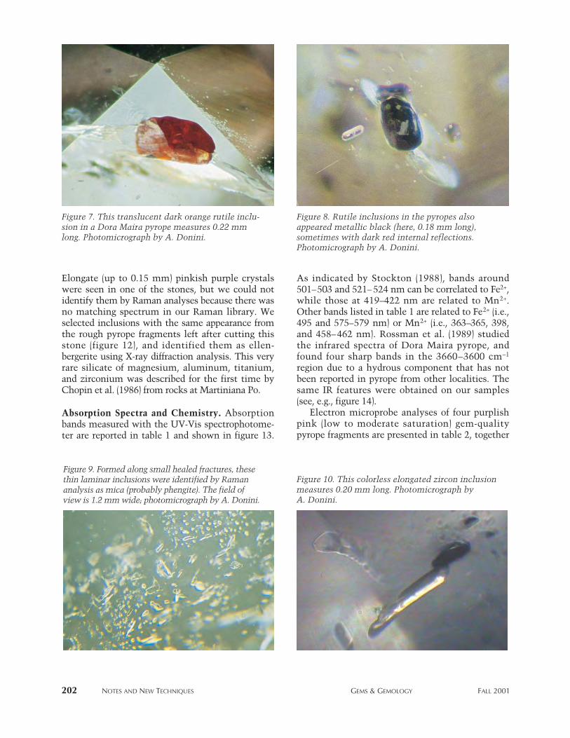
Elongate (up to 0.15 mm) pinkish purple crystalswere seen in one of the stones, but we could notidentify them by Raman analyses because there wasno matching spectrum in our Raman library. Weselected inclusions with the same appearance fromthe rough pyrope fragments left after cutting thisstone (figure 12), and identified them as ellen-bergerite using X-ray diffraction analysis. This veryrare silicate of magnesium, aluminum, titanium,and zirconium was described for the first time byChopin et al. (1986) from rocks at Martiniana Po.
Absorption Spectra and Chemistry. Absorptionbands measured with the UV-Vis spectrophotome-ter are reported in table 1 and shown in figure 13.
As indicated by Stockton (1988), bands around501–503 and 521– 524 nm can be correlated to Fe2+,while those at 419–422 nm are related to Mn2+.Other bands listed in table 1 are related to Fe2+ (i.e.,495 and 575–579 nm) or Mn2+ (i.e., 363–365, 398,and 458–462 nm). Rossman et al. (1989) studiedthe infrared spectra of Dora Maira pyrope, andfound four sharp bands in the 3660–3600 cm-1
region due to a hydrous component that has notbeen reported in pyrope from other localities. Thesame IR features were obtained on our samples(see, e.g., figure 14).
Electron microprobe analyses of four purplishpink (low to moderate saturation) gem-qualitypyrope fragments are presented in table 2, together
202 NOTES AND NEW TECHNIQUES GEMS & GEMOLOGY FALL 2001
Figure 7. This translucent dark orange rutile inclu-sion in a Dora Maira pyrope measures 0.22 mmlong. Photomicrograph by A. Donini.
Figure 8. Rutile inclusions in the pyropes alsoappeared metallic black (here, 0.18 mm long),sometimes with dark red internal reflections.Photomicrograph by A. Donini.
Figure 10. This colorless elongated zircon inclusionmeasures 0.20 mm long. Photomicrograph byA. Donini.
Figure 9. Formed along small healed fractures, thesethin laminar inclusions were identified by Ramananalysis as mica (probably phengite). The field ofview is 1.2 mm wide; photomicrograph by A. Donini.
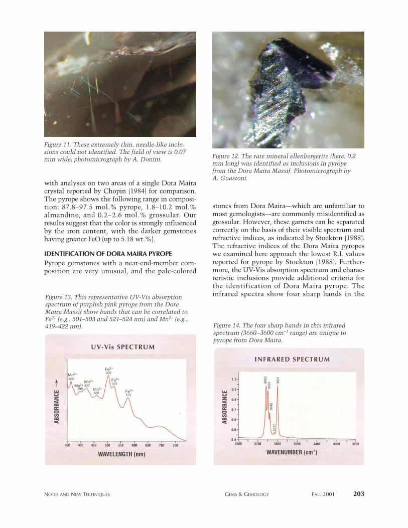
with analyses on two areas of a single Dora Mairacrystal reported by Chopin (1984) for comparison.The pyrope shows the following range in composi-tion: 87.8–97.5 mol.% pyrope, 1.8–10.2 mol.%almandine, and 0.2– 2.6 mol.% grossular. Ourresults suggest that the color is strongly influencedby the iron content, with the darker gemstoneshaving greater FeO (up to 5.18 wt.%).
IDENTIFICATION OF DORA MAIRA PYROPEPyrope gemstones with a near-end-member com-position are very unusual, and the pale-colored
stones from Dora Maira—which are unfamiliar tomost gemologists—are commonly misidentified asgrossular. However, these garnets can be separatedcorrectly on the basis of their visible spectrum andrefractive indices, as indicated by Stockton (1988).The refractive indices of the Dora Maira pyropeswe examined here approach the lowest R.I. valuesreported for pyrope by Stockton (1988). Further-more, the UV-Vis absorption spectrum and charac-teristic inclusions provide additional criteria forthe identification of Dora Maira pyrope. Theinfrared spectra show four sharp bands in the
NOTES AND NEW TECHNIQUES GEMS & GEMOLOGY FALL 2001 203
Figure 11. These extremely thin, needle-like inclu-sions could not identified. The field of view is 0.07mm wide; photomicrograph by A. Donini. Figure 12. The rare mineral ellenbergerite (here, 0.2
mm long) was identified as inclusions in pyropefrom the Dora Maira Massif. Photomicrograph byA. Guastoni.
Figure 14. The four sharp bands in this infraredspectrum (3660–3600 cm-1 range) are unique topyrope from Dora Maira.
Figure 13. This representative UV-Vis absorptionspectrum of purplish pink pyrope from the DoraMaira Massif show bands that can be correlated toFe2+ (e.g., 501–503 and 521–524 nm) and Mn2+ (e.g.,419–422 nm).

3660–3600 cm-1 region that are unique for thispyrope, and inclusions of ellenbergerite provideunequivocal evidence that a pyrope is from DoraMaira.
CONCLUSIONPyrope from the Dora Maira Massif has beenfaceted into pale purple to purplish pink gemstonesthat rarely exceed 1 ct. Although production to datehas been minor, these gem pyropes add to thegemological significance of the Alpine area, withtheir unusual color and attractiveness.
The deposit appears to be extensive, but futureproduction will undoubtedly continue to be limitedby environmental restrictions on mining. Currently,about 100 carats per year enter the marketplace, andno more than a few hundred carats have been cut.Much of the faceted pyrope is sold to private gem col-lectors, with only a few having been set in jewelry.
204 NOTES AND NEW TECHNIQUES GEMS & GEMOLOGY FALL 2001
TABLE 2. Electron microprobe analyses of pyropefrom the Dora Maira Massif, Italy.
Hue Purplish Purplish Purplish Purplish Not Notpinka pinkb pinkc pinkd reportede reported f
Saturation Low Low Low to Moderatemoderate
Oxide (wt.%)SiO2 44.46 44.13 44.02 43.52 45.21 45.13TiO2 0.02 0.01 0.04 0.03 0.00 0.02Al2O3 26.07 25.81 25.72 25.61 25.55 25.39FeOg 1.48 2.50 3.33 5.18 0.91 1.35MnO 0.02 0.05 0.05 0.08 0.02 0.03MgO 27.97 27.16 26.41 25.02 28.83 28.98CaO 0.59 0.61 0.94 0.77 0.28 0.09Total 100.61 100.27 100.51 100.21 100.80 100.99
Mol.% end-membersPyrope 95.7 92.6 91.2 87.8 97.5 97.2Almandine 2.9 4.8 6.4 10.2 1.8 2.6Grossular 1.5 2.6 2.4 2.0 0.7 0.2
a Average of 6 analyses of crystal fragments from the same materialas the 0.27, 0.32, and 0.76 ct gemstones in table 1.
b Average of 10 analyses of crystal fragments from the same materialas the 0.26, 0.49, and 0.50 ct gemstones in table 1.
c Average of 7 analyses of crystal fragments from the same materialas the 0.24 and 0.25 ct gemstones in table 1.
d Average of 9 analyses of crystal fragments from the same materialas the 0.60 and 0.85 ct gemstones in table 1.
e From Chopin (1984): rim of a 2 mm pyrope crystal. f Core of the crystal mentioned in footnote e.g Total iron as FeO.
ABOUT THE AUTHORS
Dr. Guastoni ([email protected]) is assistant curatorof mineralogy, and Dr. Pezzotta is curator of mineralogy,at the Natural History Museum of Milan, Italy. Dr.Superchi is director of CISGEM, the Gemological Centreof the Milan Chamber of Commerce. Dr. Demartin isprofessor in the Department of Structural Chemistry andInorganic Stereochemistry, University of Milan.
ACKNOWLEDGMENTS: The authors thank the staffmembers at the CISGEM laboratory (in particular, Eng.Antonello Donini) for Raman analyses, UV-Vis and FTIRspectroscopy, and photomicrography. The NationalResearch Council (CNR) Center for the Study of Alpineand Quaternary Geodynamics (Milan, Italy) is thanked forallowing access to their electron microprobe.
Also thanked are mineral collector L. Merlo Pich, whoprovided information about the locality and loaned someof the rough and cut pyrope for study, and RobertoAppiani, who photographed the pyropes.
This manuscript benefited from constructive reviews bythree referees.
REFERENCES
Chopin C. (1984) Coesite and pure pyrope in high-gradeblueschists of the Western Alps: A first record and some con-sequences. Contributions to Mineralogy and Petrology, Vol.86, pp. 107–118.
Chopin C., Klaska R., Medenbach O., Dron D. (1986)Ellenbergerite, a new high-pressure Mg-Al-(Ti,Zr)-silicatewith a novel structure based on face sharing octahedra.Contributions to Mineralogy and Petrology, Vol. 92, pp.316–321.
Deer W.A., Howie R.A., Zussman J. (1992) An Introduction tothe Rock-Forming Minerals, 2nd ed. Longman Scientific &Technical, Essex, England.
Franchi S. (1900) Sopra alcuni giacimenti di roccie giadeitichenelle Alpi occidentali e nell’Appennino ligure. Bollettino.Regio Comitato Geologico Italiano, Vol. 4, pp. 119–158.
Hofmeister A.H., Schaal R.B., Campbell K.R., Berry S.L., FaganT.J. (1998) Prevalence and origin of birefringence in 48 garnetsfrom the pyrope-almandine-grossularite-spessartine quater-
nary. American Mineralogist, Vol. 83, pp. 1293–1301.Mandarino J.A. (1999) Fleischer’s Glossary of Mineral Species.
Mineralogical Record, Tucson, Arizona, 225 pp.Rossman G.R., Beran A., Langer K. (1989) The hydrous compo-
nent of pyrope from the Dora Maira Massif, Western Alps.European Journal of Mineralogy, Vol. 1, pp. 151–154.
Schert H.P., Medenbach O. (1994) Coesit-führender-Pyrop-Quarzit-ein spektakuläres Gestein aus dem Dora-Maira-Massiv in den Westalpen. Mineralien Welt, No. 1, pp. 14–16.
Stella A. (1895) Sul rilevamento geologico eseguito nel 1894 inValle Varaita (Alpi Cozie). Bollettino Regio Comitato Geolo-gico Italiano, Vol. 26, pp. 283–313.
Stockton C.M. (1988) Pastel pyropes. Gems & Gemology, Vol.24, No. 2, pp. 104–106.
Vialon P. (1966) Etude Géologique du Massif Cristallin DoraMaira, Alpes Cottiennes Internes, Italie. M.S. thesis, Universityof Grenoble.
Webster R. (1994) Gems—Their Sources, Descriptions andIdentification, 5th ed. Revised by P.G. Read, Butterworth-Heinemann, London.
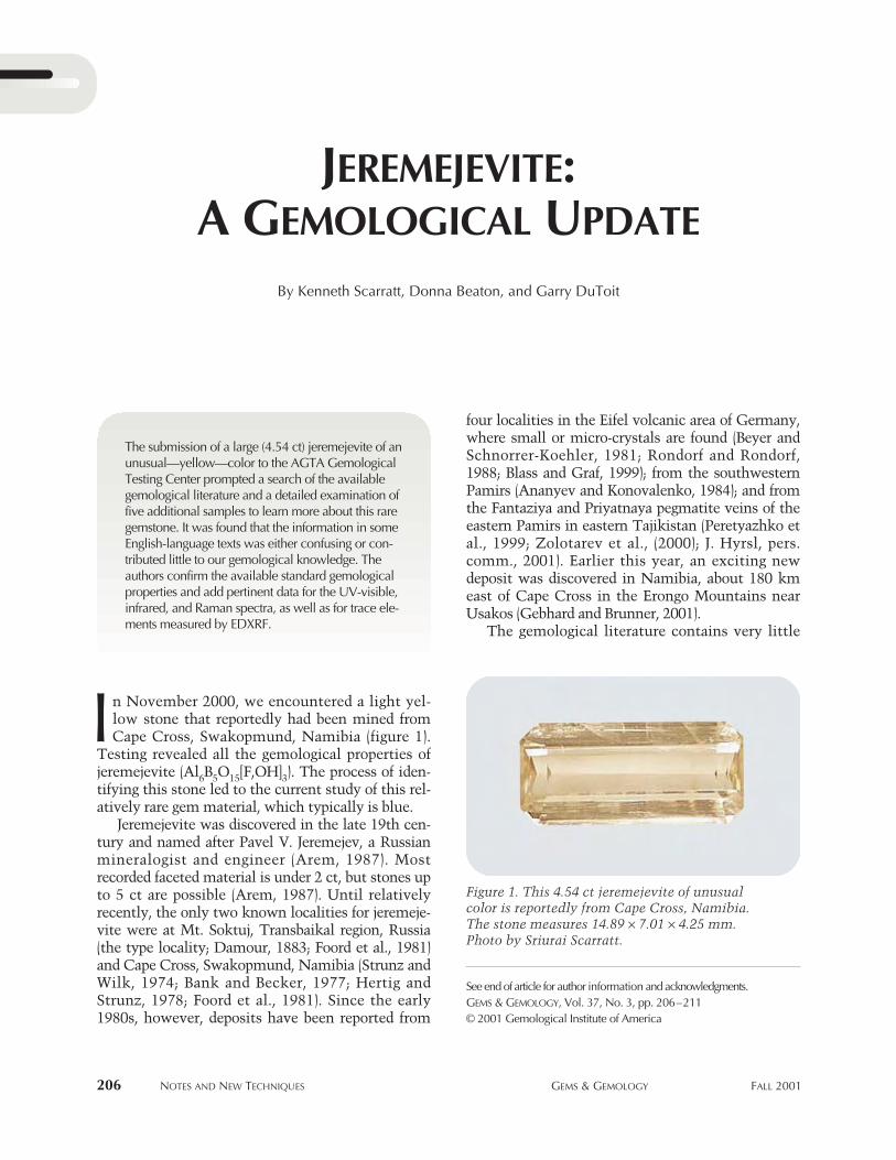
JEREMEJEVITE:A GEMOLOGICAL UPDATE
206 NOTES AND NEW TECHNIQUES GEMS & GEMOLOGY FALL 2001
four localities in the Eifel volcanic area of Germany,where small or micro-crystals are found (Beyer andSchnorrer-Koehler, 1981; Rondorf and Rondorf,1988; Blass and Graf, 1999); from the southwesternPamirs (Ananyev and Konovalenko, 1984); and fromthe Fantaziya and Priyatnaya pegmatite veins of theeastern Pamirs in eastern Tajikistan (Peretyazhko etal., 1999; Zolotarev et al., (2000); J. Hyrsl, pers.comm., 2001). Earlier this year, an exciting newdeposit was discovered in Namibia, about 180 kmeast of Cape Cross in the Erongo Mountains nearUsakos (Gebhard and Brunner, 2001).
The gemological literature contains very little
By Kenneth Scarratt, Donna Beaton, and Garry DuToit
See end of article for author information and acknowledgments.GEMS & GEMOLOGY, Vol. 37, No. 3, pp. 206–211© 2001 Gemological Institute of America
n November 2000, we encountered a light yel-low stone that reportedly had been mined fromCape Cross, Swakopmund, Namibia (figure 1).
Testing revealed all the gemological properties ofjeremejevite (Al6B5O15[F,OH]3). The process of iden-tifying this stone led to the current study of this rel-atively rare gem material, which typically is blue.
Jeremejevite was discovered in the late 19th cen-tury and named after Pavel V. Jeremejev, a Russianmineralogist and engineer (Arem, 1987). Mostrecorded faceted material is under 2 ct, but stones upto 5 ct are possible (Arem, 1987). Until relativelyrecently, the only two known localities for jeremeje-vite were at Mt. Soktuj, Transbaikal region, Russia(the type locality; Damour, 1883; Foord et al., 1981)and Cape Cross, Swakopmund, Namibia (Strunz andWilk, 1974; Bank and Becker, 1977; Hertig andStrunz, 1978; Foord et al., 1981). Since the early1980s, however, deposits have been reported from
I
The submission of a large (4.54 ct) jeremejevite of anunusual—yellow—color to the AGTA GemologicalTesting Center prompted a search of the availablegemological literature and a detailed examination offive additional samples to learn more about this raregemstone. It was found that the information in someEnglish-language texts was either confusing or con-tributed little to our gemological knowledge. Theauthors confirm the available standard gemologicalproperties and add pertinent data for the UV-visible,infrared, and Raman spectra, as well as for trace ele-ments measured by EDXRF.
Figure 1. This 4.54 ct jeremejevite of unusual color is reportedly from Cape Cross, Namibia. The stone measures 14.89 ¥ 7.01 ¥ 4.25 mm. Photo by Sriurai Scarratt.
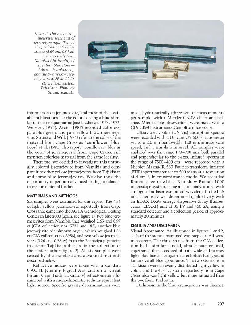
NOTES AND NEW TECHNIQUES GEMS & GEMOLOGY FALL 2001 207
information on jeremejevite, and most of the avail-able publications list the color as being a blue simi-lar to that of aquamarine (see Liddicoat, 1973, 1976;Webster, 1994). Arem (1987) recorded colorless,pale blue-green, and pale yellow-brown jeremeje-vite. Strunz and Wilk (1974) refer to the color of thematerial from Cape Cross as “cornflower” blue.Foord et al. (1981) also report “cornflower” blue asthe color of jeremejevite from Cape Cross, andmention colorless material from the same locality.
Therefore, we decided to investigate this unusu-ally colored jeremejevite from Namibia and com-pare it to other yellow jeremejevites from Tajikistanand some blue jeremejevites. We also took theopportunity to perform advanced testing, to charac-terize the material further.
MATERIALS AND METHODSSix samples were examined for this report: The 4.54ct light yellow jeremejevite reportedly from CapeCross that came into the AGTA Gemological TestingCenter in late 2000 (again, see figure 1); two blue jere-mejevites from Namibia that weighed 2.65 and 0.97ct (GIA collection nos. 5721 and 183); another bluejeremejevite of unknown origin, which weighed 1.56ct (GIA collection no. 3958); and two yellow jeremeje-vites (0.26 and 0.28 ct) from the Fantaziya pegmatitein eastern Tajikistan that are in the collection ofthe senior author (figure 2). All six samples weretested by the standard and advanced methodsdescribed below.
Refractive indices were taken with a standardGAGTL (Gemmological Association of GreatBritain Gem Trade Laboratory) refractometer illu-minated with a monochromatic sodium-equivalentlight source. Specific gravity determinations were
made hydrostatically (three sets of measurementsper sample) with a Mettler CB203 electronic bal-ance. Microscopic observations were made with aGIA GEM Instruments Gemolite microscope.
Ultraviolet-visible (UV-Vis) absorption spectrawere recorded with a Unicam UV 500 spectrometerset to a 2.0 nm bandwidth, 120 nm/minute scanspeed, and 1 nm data interval. All samples wereanalyzed over the range 190–900 nm, both paralleland perpendicular to the c-axis. Infrared spectra inthe range of 7500–400 cm-1 were recorded with aNicolet Magna-IR 560 Fourier-transform infrared(FTIR) spectrometer set to 500 scans at a resolutionof 4 cm-1, in transmittance mode. We recordedRaman spectra with a Renishaw Raman 1000microscope system, using a 1 mm analysis area withan argon-ion laser excitation wavelength of 514.5nm. Chemistry was determined qualitatively withan EDAX DX95 energy-dispersive X-ray fluores-cence (EDXRF) unit at 35 kV and 450 mA, using astandard detector and a collection period of approxi-mately 20 minutes.
RESULTS AND DISCUSSIONVisual Appearance. As illustrated in figures 1 and 2,each of the stones examined was step-cut. All weretransparent. The three stones from the GIA collec-tion had a similar banded, almost parti-colored,appearance that consisted of both wide and narrowlight blue bands set against a colorless backgroundfor an overall blue appearance. The two stones fromTajikistan were an evenly distributed light yellow incolor, and the 4.54 ct stone reportedly from CapeCross also was light yellow but more saturated thanthe two from Tajikistan.
Dichroism in the blue jeremejevites was distinct:
Figure 2. These five jere-mejevites were part of
the study sample. Two ofthe predominantly bluestones (2.65 and 0.97 ct)
are reportedly fromNamibia (the locality of
the third blue stone—1.56 ct—is unknown),
and the two yellow jere-mejevites (0.26 and 0.28
ct) are from easternTajikistan. Photo by
Sriurai Scarratt.
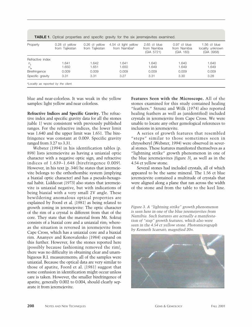
208 NOTES AND NEW TECHNIQUES GEMS & GEMOLOGY FALL 2001
blue and near-colorless. It was weak in the yellowsamples: light yellow and near colorless.
Refractive Indices and Specific Gravity. The refrac-tive index and specific gravity data for all the stones(table 1) were consistent with previously publishedranges. For the refractive indices, the lower limitwas 1.640 and the upper limit was 1.651. The bire-fringence was constant at 0.009. Specific gravityranged from 3.27 to 3.31.
Webster (1994) in his identification tables (p.898) lists jeremejevite as having a uniaxial opticcharacter with a negative optic sign, and refractiveindices of 1.639–1.648 (birefringence 0.009).However, in his text (p. 346) he states that jeremeje-vite belongs to the orthorhombic system (implyinga biaxial optic character) and has a pseudo-hexago-nal habit. Liddicoat (1973) also states that jeremeje-vite is uniaxial negative, but with indications ofbeing biaxial with a very small 2V angle. Thesebewildering anomalous optical properties areexplained by Foord et al. (1981) as being related togrowth zoning in jeremejevite: The optic characterof the rim of a crystal is different from that of thecore. They state that the material from Mt. Soktujconsists of a biaxial core and a uniaxial rim; where-as the situation is reversed in jeremejevite fromCape Cross, which has a uniaxial core and a biaxialrim. Ananyev and Konovalenko (1984) expand onthis further. However, for the stones reported here(possibly because fashioning removed the rim),there was no difficulty in obtaining clear and unam-biguous R.I. measurements; all of the samples wereuniaxial. Because the optical data are very similar tothose of apatite, Foord et al. (1981) suggest thatsome confusion in identification might occur unlesscare is taken. However, the smaller birefringence ofapatite, generally 0.002 to 0.004, should clearly sep-arate it from jeremejevite.
Features Seen with the Microscope. All of thestones examined for this study contained healing“feathers.” Strunz and Wilk (1974) also reportedhealing feathers as well as (unidentified) includedcrystals in jeremejevite from Cape Cross. We wereunable to locate any other gemological references toinclusions in jeremejevite.
A series of growth features that resembled“steps” similar to those sometimes seen inchrysoberyl (Webster, 1994) were observed in sever-al stones. These features manifested themselves as a“lightning strike” growth phenomenon in one ofthe blue jeremejevites (figure 3), as well as in the4.54 ct yellow stone.
Several stones had included crystals, all of whichappeared to be the same mineral. The 1.56 ct bluejeremejevite contained a multitude of crystals thatwere aligned along a plane that ran across the widthof the stone and from the table to the keel line.
Figure 3. A “lightning strike” growth phenomenonis seen here in one of the blue jeremejevites fromNamibia. Such features are actually a manifesta-tion of “step” growth features, which also wereseen in the 4.54 ct yellow stone. Photomicrographby Kenneth Scarratt; magnified 20¥.
TABLE 1. Optical properties and specific gravity for the six jeremejevites examined.
Property 0.28 ct yellow 0.26 ct yellow 4.54 ct light yellow 2.65 ct blue 0.97 ct blue 1.56 ct bluefrom Tajikistan from Tajikistan from Namibiaa from Namibia from Namibia locality unknown
(GIA 5721) (GIA 183) (GIA 3958)
Refractive indexne 1.641 1.642 1.641 1.640 1.640 1.640nw 1.650 1.651 1.650 1.649 1.649 1.649Birefringence 0.009 0.009 0.009 0.009 0.009 0.009Specific gravity 3.31 3.31 3.27 3.31 3.30 3.28
aLocality as reported by the client.
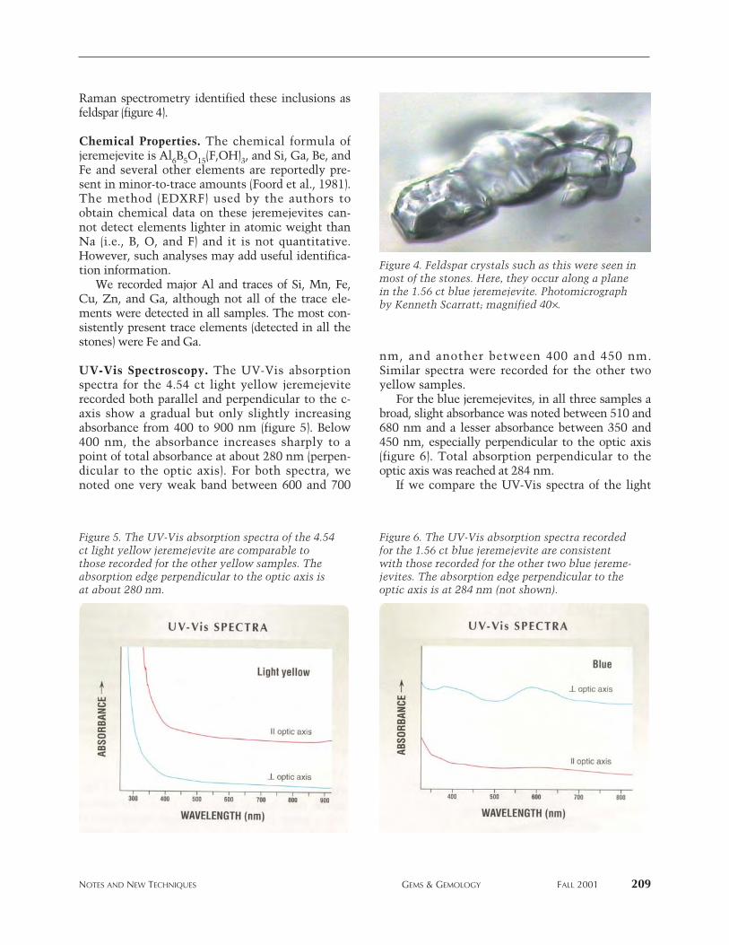
NOTES AND NEW TECHNIQUES GEMS & GEMOLOGY FALL 2001 209
Raman spectrometry identified these inclusions asfeldspar (figure 4).
Chemical Properties. The chemical formula ofjeremejevite is Al6B5O15(F,OH)3, and Si, Ga, Be, andFe and several other elements are reportedly pre-sent in minor-to-trace amounts (Foord et al., 1981).The method (EDXRF) used by the authors toobtain chemical data on these jeremejevites can-not detect elements lighter in atomic weight thanNa (i.e., B, O, and F) and it is not quantitative.However, such analyses may add useful identifica-tion information.
We recorded major Al and traces of Si, Mn, Fe,Cu, Zn, and Ga, although not all of the trace ele-ments were detected in all samples. The most con-sistently present trace elements (detected in all thestones) were Fe and Ga.
UV-Vis Spectroscopy. The UV-Vis absorptionspectra for the 4.54 ct light yellow jeremejeviterecorded both parallel and perpendicular to the c-axis show a gradual but only slightly increasingabsorbance from 400 to 900 nm (figure 5). Below400 nm, the absorbance increases sharply to apoint of total absorbance at about 280 nm (perpen-dicular to the optic axis). For both spectra, wenoted one very weak band between 600 and 700
nm, and another between 400 and 450 nm.Similar spectra were recorded for the other twoyellow samples.
For the blue jeremejevites, in all three samples abroad, slight absorbance was noted between 510 and680 nm and a lesser absorbance between 350 and450 nm, especially perpendicular to the optic axis(figure 6). Total absorption perpendicular to theoptic axis was reached at 284 nm.
If we compare the UV-Vis spectra of the light
Figure 5. The UV-Vis absorption spectra of the 4.54ct light yellow jeremejevite are comparable tothose recorded for the other yellow samples. Theabsorption edge perpendicular to the optic axis isat about 280 nm.
Figure 6. The UV-Vis absorption spectra recordedfor the 1.56 ct blue jeremejevite are consistentwith those recorded for the other two blue jereme-jevites. The absorption edge perpendicular to theoptic axis is at 284 nm (not shown).
Figure 4. Feldspar crystals such as this were seen inmost of the stones. Here, they occur along a planein the 1.56 ct blue jeremejevite. Photomicrographby Kenneth Scarratt; magnified 40¥.
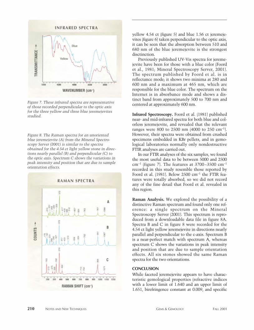
yellow 4.54 ct (figure 5) and blue 1.56 ct jeremeje-vites (figure 6) taken perpendicular to the optic axis,it can be seen that the absorption between 510 and680 nm of the blue jeremejevite is the strongestdisctinction.
Previously published UV-Vis spectra for jereme-jevite have been for those with a blue color (Foordet al., 1981; Mineral Spectroscopy Server, 2001).The spectrum published by Foord et al. is inreflectance mode; it shows two minima at 280 and600 nm and a maximum at 465 nm, which areresponsible for the blue color. The spectrum on theInternet is in absorbance mode and shows a dis-tinct band from approximately 500 to 700 nm andcentered at approximately 600 nm.
Infrared Spectroscopy. Foord et al. (1981) publishednear- and mid-infrared spectra for both blue and col-orless jeremejevite, and revealed that the relevantranges were 800 to 2500 nm (4000 to 250 cm-1).However, their spectra were obtained from crushedspecimens embedded in KBr pellets, and in gemo-logical laboratories normally only nondestructiveFTIR analyses are carried out.
In our FTIR analyses of the six samples, we foundthe most useful data to be between 5000 and 2500cm-1 (figure 7). The features at 3700–3500 cm-1
recorded in this study resemble those reported byFoord et al. (1981). Below 2500 cm-1 the FTIR fea-tures were totally absorbed, so we did not recordany of the fine detail that Foord et al. revealed inthis region.
Raman Analysis. We explored the possibility of adistinctive Raman spectrum and found only one ref-erence: a single spectrum on the MineralSpectroscopy Server (2001). This spectrum is repro-duced from a downloadable data file in figure 8A.Spectra B and C in figure 8 were recorded for the4.54 ct light yellow jeremejevite in directions nearlyparallel and perpendicular to the c-axis. Spectrum Bis a near-perfect match with spectrum A, whereasspectrum C shows the variations in peak intensityand position that are due to sample orientationeffects. All six stones showed the same Ramanspectra for the two orientations.
CONCLUSIONWhile faceted jeremejevite appears to have charac-teristic gemological properties (refractive indiceswith a lower limit of 1.640 and an upper limit of1.651, birefringence constant at 0.009, and specific
210 NOTES AND NEW TECHNIQUES GEMS & GEMOLOGY FALL 2001
Figure 7. These infrared spectra are representativeof those recorded perpendicular to the optic axisfor the three yellow and three blue jeremejevitesstudied.
Figure 8. The Raman spectra for an unorientedblue jeremejevite (A) from the Mineral Spectro-scopy Server (2001) is similar to the spectraobtained for the 4.54 ct light yellow stone in direc-tions nearly parallel (B) and perpendicular (C) tothe optic axis. Spectrum C shows the variations inpeak intensity and position that are due to sampleorientation effects.
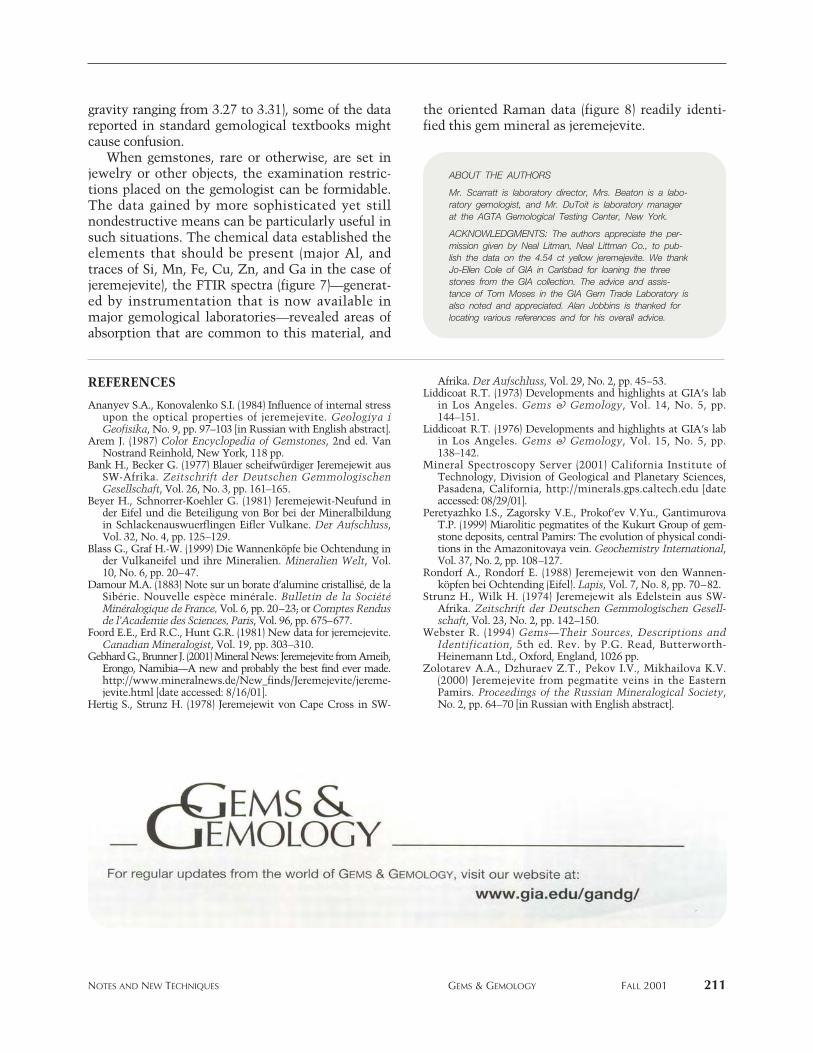
gravity ranging from 3.27 to 3.31), some of the datareported in standard gemological textbooks mightcause confusion.
When gemstones, rare or otherwise, are set injewelry or other objects, the examination restric-tions placed on the gemologist can be formidable.The data gained by more sophisticated yet stillnondestructive means can be particularly useful insuch situations. The chemical data established theelements that should be present (major Al, andtraces of Si, Mn, Fe, Cu, Zn, and Ga in the case ofjeremejevite), the FTIR spectra (figure 7)—generat-ed by instrumentation that is now available inmajor gemological laboratories—revealed areas ofabsorption that are common to this material, and
the oriented Raman data (figure 8) readily identi-fied this gem mineral as jeremejevite.
NOTES AND NEW TECHNIQUES GEMS & GEMOLOGY FALL 2001 211
ABOUT THE AUTHORS
Mr. Scarratt is laboratory director, Mrs. Beaton is a labo-ratory gemologist, and Mr. DuToit is laboratory manager at the AGTA Gemological Testing Center, New York.
ACKNOWLEDGMENTS: The authors appreciate the per-mission given by Neal Litman, Neal Littman Co., to pub-lish the data on the 4.54 ct yellow jeremejevite. We thankJo-Ellen Cole of GIA in Carlsbad for loaning the threestones from the GIA collection. The advice and assis-tance of Tom Moses in the GIA Gem Trade Laboratory isalso noted and appreciated. Alan Jobbins is thanked forlocating various references and for his overall advice.
REFERENCES
Ananyev S.A., Konovalenko S.I. (1984) Influence of internal stressupon the optical properties of jeremejevite. Geologiya iGeofisika, No. 9, pp. 97–103 [in Russian with English abstract].
Arem J. (1987) Color Encyclopedia of Gemstones, 2nd ed. VanNostrand Reinhold, New York, 118 pp.
Bank H., Becker G. (1977) Blauer scheifwürdiger Jeremejewit ausSW-Afrika. Zeitschrift der Deutschen GemmologischenGesellschaft, Vol. 26, No. 3, pp. 161–165.
Beyer H., Schnorrer-Koehler G. (1981) Jeremejewit-Neufund inder Eifel und die Beteiligung von Bor bei der Mineralbildungin Schlackenauswuerflingen Eifler Vulkane. Der Aufschluss,Vol. 32, No. 4, pp. 125–129.
Blass G., Graf H.-W. (1999) Die Wannenköpfe bie Ochtendung inder Vulkaneifel und ihre Mineralien. Mineralien Welt, Vol.10, No. 6, pp. 20–47.
Damour M.A. (1883) Note sur un borate d’alumine cristallisé, de laSibérie. Nouvelle espèce minérale. Bulletin de la SociétéMinéralogique de France, Vol. 6, pp. 20–23; or Comptes Rendusde l’Academie des Sciences, Paris, Vol. 96, pp. 675–677.
Foord E.E., Erd R.C., Hunt G.R. (1981) New data for jeremejevite.Canadian Mineralogist, Vol. 19, pp. 303–310.
Gebhard G., Brunner J. (2001) Mineral News: Jeremejevite from Ameib,Erongo, Namibia—A new and probably the best find ever made.http://www.mineralnews.de/New_finds/Jeremejevite/jereme-jevite.html [date accessed: 8/16/01].
Hertig S., Strunz H. (1978) Jeremejewit von Cape Cross in SW-
Afrika. Der Aufschluss, Vol. 29, No. 2, pp. 45–53.Liddicoat R.T. (1973) Developments and highlights at GIA’s lab
in Los Angeles. Gems & Gemology, Vol. 14, No. 5, pp.144–151.
Liddicoat R.T. (1976) Developments and highlights at GIA’s labin Los Angeles. Gems & Gemology, Vol. 15, No. 5, pp.138–142.
Mineral Spectroscopy Server (2001) California Institute ofTechnology, Division of Geological and Planetary Sciences,Pasadena, California, http://minerals.gps.caltech.edu [dateaccessed: 08/29/01].
Peretyazhko I.S., Zagorsky V.E., Prokof’ev V.Yu., GantimurovaT.P. (1999) Miarolitic pegmatites of the Kukurt Group of gem-stone deposits, central Pamirs: The evolution of physical condi-tions in the Amazonitovaya vein. Geochemistry International,Vol. 37, No. 2, pp. 108–127.
Rondorf A., Rondorf E. (1988) Jeremejewit von den Wannen-köpfen bei Ochtending (Eifel). Lapis, Vol. 7, No. 8, pp. 70–82.
Strunz H., Wilk H. (1974) Jeremejewit als Edelstein aus SW-Afrika. Zeitschrift der Deutschen Gemmologischen Gesell-schaft, Vol. 23, No. 2, pp. 142–150.
Webster R. (1994) Gems—Their Sources, Descriptions andIdentification, 5th ed. Rev. by P.G. Read, Butterworth-Heinemann Ltd., Oxford, England, 1026 pp.
Zolotarev A.A., Dzhuraev Z.T., Pekov I.V., Mikhailova K.V.(2000) Jeremejevite from pegmatite veins in the EasternPamirs. Proceedings of the Russian Mineralogical Society,No. 2, pp. 64–70 [in Russian with English abstract].
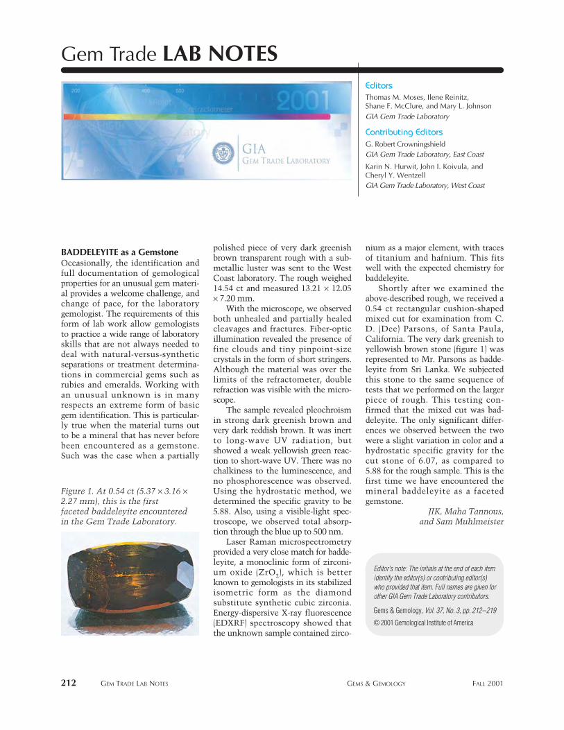
BADDELEYITE as a GemstoneOccasionally, the identification andfull documentation of gemologicalproperties for an unusual gem materi-al provides a welcome challenge, andchange of pace, for the laboratorygemologist. The requirements of thisform of lab work allow gemologiststo practice a wide range of laboratoryskills that are not always needed todeal with natural-versus-syntheticseparations or treatment determina-tions in commercial gems such asrubies and emeralds. Working withan unusual unknown is in manyrespects an extreme form of basicgem identification. This is particular-ly true when the material turns outto be a mineral that has never beforebeen encountered as a gemstone.Such was the case when a partially
polished piece of very dark greenishbrown transparent rough with a sub-metallic luster was sent to the WestCoast laboratory. The rough weighed14.54 ct and measured 13.21 ¥ 12.05¥ 7.20 mm.
With the microscope, we observedboth unhealed and partially healedcleavages and fractures. Fiber-opticillumination revealed the presence offine clouds and tiny pinpoint-sizecrystals in the form of short stringers.Although the material was over thelimits of the refractometer, doublerefraction was visible with the micro-scope.
The sample revealed pleochroismin strong dark greenish brown andvery dark reddish brown. It was inertto long-wave UV radiation, butshowed a weak yellowish green reac-tion to short-wave UV. There was nochalkiness to the luminescence, andno phosphorescence was observed.Using the hydrostatic method, wedetermined the specific gravity to be5.88. Also, using a visible-light spec-troscope, we observed total absorp-tion through the blue up to 500 nm.
Laser Raman microspectrometryprovided a very close match for badde-leyite, a monoclinic form of zirconi-um oxide (ZrO2), which is betterknown to gemologists in its stabilizedisometric form as the diamond substitute synthetic cubic zirconia. Energy-dispersive X-ray fluorescence (EDXRF) spectroscopy showed thatthe unknown sample contained zirco-
nium as a major element, with tracesof titanium and hafnium. This fitswell with the expected chemistry forbaddeleyite.
Shortly after we examined theabove-described rough, we received a0.54 ct rectangular cushion-shapedmixed cut for examination from C.D. (Dee) Parsons, of Santa Paula,California. The very dark greenish toyellowish brown stone (figure 1) wasrepresented to Mr. Parsons as badde-leyite from Sri Lanka. We subjectedthis stone to the same sequence oftests that we performed on the largerpiece of rough. This testing con-firmed that the mixed cut was bad-deleyite. The only significant differ-ences we observed between the twowere a slight variation in color and ahydrostatic specific gravity for thecut stone of 6.07, as compared to5.88 for the rough sample. This is thefirst time we have encountered themineral baddeleyite as a facetedgemstone.
JIK, Maha Tannous,and Sam Muhlmeister
212 GEM TRADE LAB NOTES GEMS & GEMOLOGY FALL 2001
EditorsThomas M. Moses, Ilene Reinitz, Shane F. McClure, and Mary L. JohnsonGIA Gem Trade Laboratory
Contributing EditorsG. Robert CrowningshieldGIA Gem Trade Laboratory, East Coast
Karin N. Hurwit, John I. Koivula, and Cheryl Y. WentzellGIA Gem Trade Laboratory, West Coast
Gem Trade LAB NOTES
© 2001 Gemological Institute of America
Gems & Gemology, Vol. 37, No. 3, pp. 212–219
Editor’s note: The initials at the end of each itemidentify the editor(s) or contributing editor(s)who provided that item. Full names are given forother GIA Gem Trade Laboratory contributors.
Figure 1. At 0.54 ct (5.37 ¥ 3.16 ¥2.27 mm), this is the firstfaceted baddeleyite encounteredin the Gem Trade Laboratory.
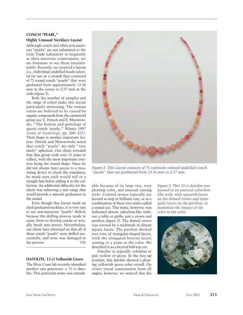
CONCH “PEARL,”Highly Unusual Necklace LayoutAlthough conch and other non-nacre-ous “pearls” are not submitted to theGem Trade Laboratory as frequentlyas their nacreous counterparts, weare fortunate to see them intermit-tently. Recently, we received a layout(i.e., individual undrilled beads select-ed for use as a strand) that consistedof 75 round conch “pearls” that weregraduated from approximately 13.56mm in the center to 2.57 mm at theends (figure 2).
Both the number of samples andthe range of colors make this layoutparticularly interesting. The variouscolors are believed to be caused byorganic compounds from the carotenoidgroup (see E. Fritsch and E. Misiorow-ski, “The history and gemology ofqueen conch ‘pearls,’” Winter 1987Gems & Gemology, pp. 208–221).Their shape is another important fea-ture. Fritsch and Misiorowski notedthat conch “pearls” are only “veryrarely” spherical. Our client revealedthat this group took over 15 years tocollect, with the most important crite-rion being the round shape. Since hedid not always have access to a mea-suring device to check the roundness,he made sure each would roll in astraight line before adding it to the col-lection. An additional difficulty for theclient was achieving a size range thatwould provide a smooth graduation inthe strand.
Even though this layout made anideal graduated necklace, it is very rareto see non-nacreous “pearls” drilled,because the drilling process tends tocause them to develop cracks or actu-ally break into pieces. Nevertheless,our client later informed us that all ofthese conch “pearls” were drilled suc-cessfully, and none was damaged inthe process. TM
DATOLITE, 13 ct Yellowish Green The West Coast lab recently identifiedanother rare gemstone: a 13 ct dato-lite. This particular stone was remark-
able because of its large size, verypleasing color, and unusual cuttingstyle. Colored stones typically arefaceted as step or brilliant cuts, or as acombination of these two styles calleda mixed cut. This stone, however, wasfashioned almost cabochon-like with-out a table or girdle, just a crown andpavilion (figure 3). The domed crownwas covered by a multitude of almostsquare facets. The pavilion showedtwo rows of triangular-shaped facets,with the elongated bottom facetscoming to a point at the culet. Wedescribed it as a faceted buff-top cut.
Datolite is typically colorless orpale yellow or green. In the face-upposition, this datolite showed a pleas-ing yellowish green color overall. Oncloser visual examination from allangles, however, we noticed that the
GEM TRADE LAB NOTES GEMS & GEMOLOGY FALL 2001 213
Figure 2. This layout consists of 75 variously colored undrilled conch“pearls” that are graduated from 13.56 mm to 2.57 mm.
Figure 3. This 13 ct datolite wasfaceted in an unusual cabochon-like style, with squarish facetson the domed crown and trian-gular facets on the pavilion, tomaximize the impact of thecolor in the culet.
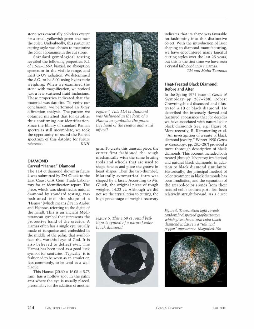
214 GEM TRADE LAB NOTES GEMS & GEMOLOGY FALL 2001
stone was essentially colorless exceptfor a small yellowish green area nearthe culet. Undoubtedly, this particularcutting style was chosen to maximizethe color appearance in the cut stone.
Standard gemological testingrevealed the following properties: R.I.of 1.622–1.669, biaxial, no absorptionspectrum in the visible range, andinert to UV radiation. We determinedthe S.G. to be 3.00 using hydrostaticweighing. When we examined thestone with magnification, we noticedjust a few scattered fluid inclusions.These properties indicated that thematerial was datolite. To verify ourconclusion, we performed an X-raydiffraction analysis. The pattern weobtained matched that for datolite,thus confirming our identification.Since the library of standard Ramanspectra is still incomplete, we tookthe opportunity to record the Ramanspectrum of this datolite for futurereference. KNH
DIAMONDCarved “Hamsa” DiamondThe 11.4 ct diamond shown in figure4 was submitted by Zvi Gluck to theEast Coast GIA Gem Trade Labora-tory for an identification report. Thepiece, which was identified as naturaldiamond by standard testing, wasfashioned into the shape of a"Hamsa" (which means five in Arabicand Hebrew, referring to the digits ofthe hand). This is an ancient Medi-terranean symbol that represents theprotective hand of the creator. AHamsa often has a single eye, usuallymade of turquoise and embedded inthe middle of the palm, that symbol-izes the watchful eye of God. It isalso believed to deflect evil. TheHamsa has been used as a good lucksymbol for centuries. Typically, it isfashioned to be worn as an amulet or,less commonly, to be used as a wallplaque.
This Hamsa (20.60 ¥ 16.08 ¥ 5.75mm) has a hollow spot in the palmarea where the eye is usually placed,presumably for the addition of another
gem. To create this unusual piece, thecutter first fashioned the roughmechanically with the same brutingtools and wheels that are used toshape fancies and place the groove inheart shapes. Then the two-thumbed,bilaterally symmetrical form wasshaped by a laser. According to Mr.Gluck, the original piece of roughweighed 14.22 ct. Although we didnot see the crystal prior to cutting, thehigh percentage of weight recovery
indicates that its shape was favorablefor fashioning into this distinctiveobject. With the introduction of lasershaping to diamond manufacturing,we have encountered many fancifulcutting styles over the last 25 years,but this is the first time we have seena crystal fashioned into a Hamsa.
TM and Maha Tannous
Heat-Treated Black Diamond:Before and AfterIn the Spring 1971 issue of Gems &Gemology (pp. 287– 288), RobertCrowningshield discussed and illus-trated a 10 ct black diamond. Hedescribed the intensely flawed andfractured appearance that for decadeswe have associated with natural-colorblack diamonds (see, e.g., figure 5).More recently, R. Kammerling et al.(“An investigation of a suite of blackdiamond jewelry,” Winter 1990 Gems& Gemology, pp. 282–287) provided amore thorough description of blackdiamonds. This account included bothtreated (through laboratory irradiation)and natural black diamonds, in addi-tion to black diamond simulants.Historically, the principal method ofcolor treatment in black diamonds hasbeen irradiation, and the separation ofthe treated-color stones from theirnatural-color counterparts has beenrelatively straightforward. As a direct
Figure 4. This 11.4 ct diamondwas fashioned in the form of aHamsa to symbolize the protec-tive hand of the creator and wardoff evil.
Figure 5. This 1.58 ct round bril-liant is typical of a natural-colorblack diamond.
Figure 6. Transmitted light revealsrandomly dispersed graphitization,which gives the natural-color blackdiamond in figure 5 a “salt andpepper” appearance. Magnified 15¥.
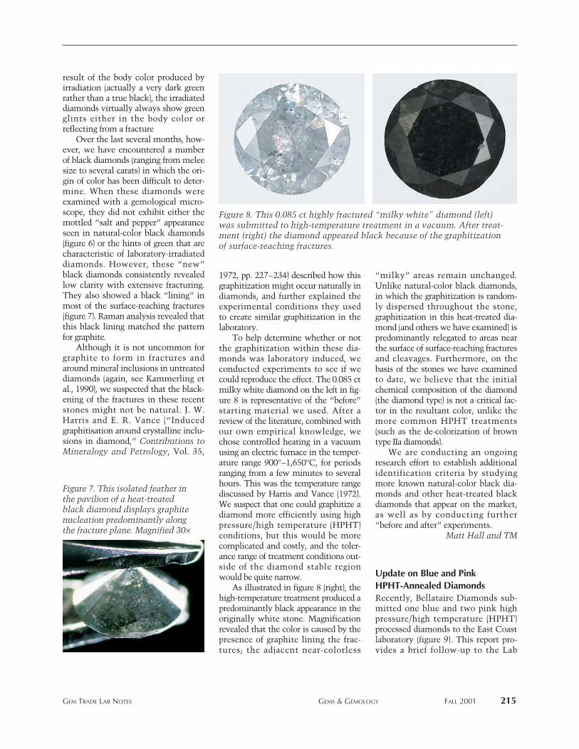
result of the body color produced byirradiation (actually a very dark greenrather than a true black), the irradiateddiamonds virtually always show greenglints either in the body color orreflecting from a fracture
Over the last several months, how-ever, we have encountered a numberof black diamonds (ranging from meleesize to several carats) in which the ori-gin of color has been difficult to deter-mine. When these diamonds wereexamined with a gemological micro-scope, they did not exhibit either themottled “salt and pepper” appearanceseen in natural-color black diamonds(figure 6) or the hints of green that arecharacteristic of laboratory-irradiateddiamonds. However, these “new”black diamonds consistently revealedlow clarity with extensive fracturing.They also showed a black “lining” inmost of the surface-reaching fractures(figure 7). Raman analysis revealed thatthis black lining matched the patternfor graphite.
Although it is not uncommon forgraphite to form in fractures andaround mineral inclusions in untreateddiamonds (again, see Kammerling etal., 1990), we suspected that the black-ening of the fractures in these recentstones might not be natural. J. W.Harris and E. R. Vance (“Inducedgraphitisation around crystalline inclu-sions in diamond,” Contributions toMineralogy and Petrology, Vol. 35,
1972, pp. 227–234) described how thisgraphitization might occur naturally indiamonds, and further explained theexperimental conditions they used to create similar graphitization in thelaboratory.
To help determine whether or notthe graphitization within these dia-monds was laboratory induced, weconducted experiments to see if wecould reproduce the effect. The 0.085 ctmilky white diamond on the left in fig-ure 8 is representative of the “before”starting material we used. After areview of the literature, combined withour own empirical knowledge, wechose controlled heating in a vacuumusing an electric furnace in the temper-ature range 900°–1,650°C, for periodsranging from a few minutes to severalhours. This was the temperature rangediscussed by Harris and Vance (1972).We suspect that one could graphitize adiamond more efficiently using highpressure/high temperature (HPHT)conditions, but this would be morecomplicated and costly, and the toler-ance range of treatment conditions out-side of the diamond stable regionwould be quite narrow.
As illustrated in figure 8 (right), thehigh-temperature treatment produced apredominantly black appearance in theoriginally white stone. Magnificationrevealed that the color is caused by thepresence of graphite lining the frac-tures; the adjacent near-colorless
“milky” areas remain unchanged.Unlike natural-color black diamonds,in which the graphitization is random-ly dispersed throughout the stone,graphitization in this heat-treated dia-mond (and others we have examined) ispredominantly relegated to areas nearthe surface of surface-reaching fracturesand cleavages. Furthermore, on thebasis of the stones we have examinedto date, we believe that the initialchemical composition of the diamond(the diamond type) is not a critical fac-tor in the resultant color, unlike themore common HPHT treatments(such as the de-colorization of browntype IIa diamonds).
We are conducting an ongoingresearch effort to establish additionalidentification criteria by studyingmore known natural-color black dia-monds and other heat-treated blackdiamonds that appear on the market,as well as by conducting further“before and after” experiments.
Matt Hall and TM
Update on Blue and PinkHPHT-Annealed DiamondsRecently, Bellataire Diamonds sub-mitted one blue and two pink highpressure/high temperature (HPHT)processed diamonds to the East Coastlaboratory (figure 9). This report pro-vides a brief follow-up to the Lab
GEM TRADE LAB NOTES GEMS & GEMOLOGY FALL 2001 215
Figure 8. This 0.085 ct highly fractured “milky white” diamond (left)was submitted to high-temperature treatment in a vacuum. After treat-ment (right) the diamond appeared black because of the graphitizationof surface-reaching fractures.
Figure 7. This isolated feather inthe pavilion of a heat-treatedblack diamond displays graphitenucleation predominantly alongthe fracture plane. Magnified 30¥
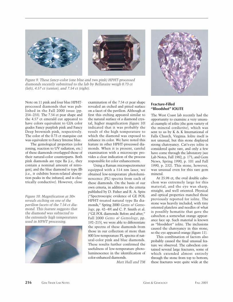
216 GEM TRADE LAB NOTES GEMS & GEMOLOGY FALL 2001
Note on 11 pink and four blue HPHT-processed diamonds that was pub-lished in the Fall 2000 issue (pp.254–255). The 7.54 ct pear shape andthe 4.57 ct emerald cut appeared tohave colors equivalent to GIA colorgrades Fancy purplish pink and FancyDeep brownish pink, respectively.The color of the 0.73 ct marquise cutwas equivalent to Fancy Intense blue.
The gemological properties (colorzoning, reaction to UV radiation, etc.)of these diamonds overlapped those oftheir natural-color counterparts. Bothpink diamonds are type IIa (i.e., theycontain a nominal amount of nitro-gen), and the blue diamond is type IIb(i.e., it exhibits boron-related absorp-tion peaks in the infrared, and is elec-trically conductive). However, close
examination of the 7.54 ct pear shaperevealed an etched and pitted surfaceon a facet of the pavilion. Although atfirst this etching appeared similar tothe natural surface of a diamond crys-tal, higher magnification (figure 10)indicated that it was probably theresult of the high temperature towhich the diamond was exposed toenhance its color. We have noted thisfeature in other HPHT-processed dia-monds. When it is present, carefulexamination with a microscope pro-vides a clear indication of the processresponsible for color enhancement.
Using a Raman microspectrometerequipped with a 514 nm laser, weobtained low-temperature photolumi-nescence (PL) spectra from each ofthese diamonds. On the basis of ourown criteria, in addition to the criteriapublished by D. Fisher and R. A. Spits(“Spectroscopic evidence of GE POLHPHT-treated natural type IIa dia-monds,” Spring 2000 Gems & Gemo-logy, pp. 42–49) and C. P. Smith et al.(“GE POL diamonds: Before and after,”Fall 2000 Gems & Gemology, pp.192–215), we were able to differentiatethe spectra of these diamonds fromthose in our collection of more than800 low-temperature PL spectra of nat-ural-color pink and blue diamonds.These results further confirmed theusefulness of low-temperature photo-luminescence in the identification ofcolor-enhanced diamonds.
Matt Hall and TM
Fracture-Filled “Bloodshot” IOLITE
The West Coast lab recently had theopportunity to examine a very unusu-al example of iolite (the gem variety ofthe mineral cordierite), which wassent to us by K & K International ofFalls Church, Virginia. Iolite itself isnot unusual, but this stone displayedstrong chatoyancy. Cat’s-eye iolite isconsidered quite rare, and only a fewhave come through the laboratory (seeLab Notes, Fall 1982, p. 171; and GemNews, Spring 1990, p. 101 and Fall1990, p. 232). This stone, however,was unusual even for this rare gemmineral.
At 25.98 ct, the oval double cabo-chon was extremely large for thismaterial, and the eye was sharp,straight, and well oriented. Physicaland optical properties matched thosepreviously reported for iolite. Thestone was heavily included, with tinyoriented platelets and needles of whatis possibly hematite that gave thecabochon a somewhat orange appear-ance face up. Such material is knownas “bloodshot” iolite. The inclusionscaused the chatoyancy in this stone,so the eye appeared orange (figure 11).
This combination of factors alsoprobably caused the final unusual fea-ture we observed. The cabochon con-tained several large fractures, some ofwhich extended almost entirelythrough the stone from top to bottom;these fractures were quite wide at the
Figure 10. Magnification at 30¥reveals etching on one of thepavilion facets of the 7.54 ct dia-mond. This feature suggests thatthe diamond was subjected tothe extremely high temperaturesused in HPHT processing.
Figure 9. These fancy-color (one blue and two pink) HPHT-processeddiamonds recently submitted to the lab by Bellataire weigh 0.73 ct(left), 4.57 ct (center), and 7.54 ct (right).
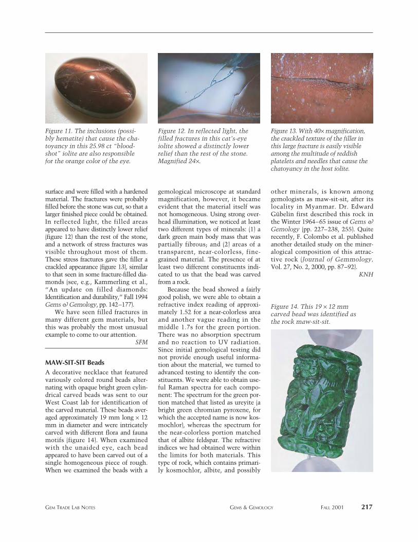
surface and were filled with a hardenedmaterial. The fractures were probablyfilled before the stone was cut, so that alarger finished piece could be obtained.In reflected light, the filled areasappeared to have distinctly lower relief(figure 12) than the rest of the stone,and a network of stress fractures wasvisible throughout most of them.These stress fractures gave the filler acrackled appearance (figure 13), similarto that seen in some fracture-filled dia-monds (see, e.g., Kammerling et al.,“An update on filled diamonds:Identification and durability,” Fall 1994Gems & Gemology, pp. 142–177).
We have seen filled fractures inmany different gem materials, butthis was probably the most unusualexample to come to our attention.
SFM
MAW-SIT-SIT Beads A decorative necklace that featuredvariously colored round beads alter-nating with opaque bright green cylin-drical carved beads was sent to ourWest Coast lab for identification ofthe carved material. These beads aver-aged approximately 19 mm long ¥ 12mm in diameter and were intricatelycarved with different flora and faunamotifs (figure 14). When examinedwith the unaided eye, each beadappeared to have been carved out of asingle homogeneous piece of rough.When we examined the beads with a
gemological microscope at standardmagnification, however, it becameevident that the material itself wasnot homogeneous. Using strong over-head illumination, we noticed at leasttwo different types of minerals: (1) adark green main body mass that waspartially fibrous; and (2) areas of atransparent, near-colorless, fine-grained material. The presence of atleast two different constituents indi-cated to us that the bead was carvedfrom a rock.
Because the bead showed a fairlygood polish, we were able to obtain arefractive index reading of approxi-mately 1.52 for a near-colorless areaand another vague reading in themiddle 1.7s for the green portion.There was no absorption spectrumand no reaction to UV radiation.Since initial gemological testing didnot provide enough useful informa-tion about the material, we turned toadvanced testing to identify the con-stituents. We were able to obtain use-ful Raman spectra for each compo-nent: The spectrum for the green por-tion matched that listed as ureyite (abright green chromian pyroxene, forwhich the accepted name is now kos-mochlor), whereas the spectrum forthe near-colorless portion matchedthat of albite feldspar. The refractiveindices we had obtained were withinthe limits for both materials. Thistype of rock, which contains primari-ly kosmochlor, albite, and possibly
other minerals, is known amonggemologists as maw-sit-sit, after itslocality in Myanmar. Dr. EdwardGübelin first described this rock inthe Winter 1964–65 issue of Gems &Gemology (pp. 227–238, 255). Quiterecently, F. Colombo et al. publishedanother detailed study on the miner-alogical composition of this attrac-tive rock (Journal of Gemmology,Vol. 27, No. 2, 2000, pp. 87–92).
KNH
GEM TRADE LAB NOTES GEMS & GEMOLOGY FALL 2001 217
Figure 14. This 19 ¥ 12 mmcarved bead was identified asthe rock maw-sit-sit.
Figure 11. The inclusions (possi-bly hematite) that cause the cha-toyancy in this 25.98 ct “blood-shot” iolite are also responsiblefor the orange color of the eye.
Figure 12. In reflected light, thefilled fractures in this cat’s-eyeiolite showed a distinctly lowerrelief than the rest of the stone.Magnified 24¥.
Figure 13. With 40¥ magnification,the crackled texture of the filler inthis large fracture is easily visibleamong the multitude of reddishplatelets and needles that cause thechatoyancy in the host iolite.
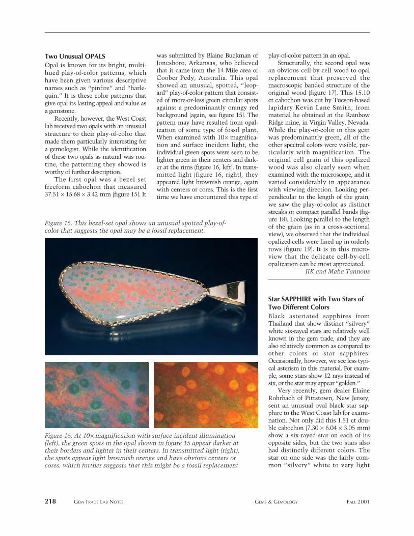
Two Unusual OPALSOpal is known for its bright, multi-hued play-of-color patterns, whichhave been given various descriptivenames such as “pinfire” and “harle-quin.” It is these color patterns thatgive opal its lasting appeal and value asa gemstone.
Recently, however, the West Coastlab received two opals with an unusualstructure to their play-of-color thatmade them particularly interesting fora gemologist. While the identificationof these two opals as natural was rou-tine, the patterning they showed isworthy of further description.
The first opal was a bezel-setfreeform cabochon that measured37.51 ¥ 15.68 ¥ 3.42 mm (figure 15). It
was submitted by Blaine Buckman ofJonesboro, Arkansas, who believedthat it came from the 14-Mile area ofCoober Pedy, Australia. This opalshowed an unusual, spotted, “leop-ard” play-of-color pattern that consist-ed of more-or-less green circular spotsagainst a predominantly orangy redbackground (again, see figure 15). Thepattern may have resulted from opal-ization of some type of fossil plant.When examined with 10¥ magnifica-tion and surface incident light, theindividual green spots were seen to belighter green in their centers and dark-er at the rims (figure 16, left). In trans-mitted light (figure 16, right), theyappeared light brownish orange, againwith centers or cores. This is the firsttime we have encountered this type of
play-of-color pattern in an opal.Structurally, the second opal was
an obvious cell-by-cell wood-to-opalreplacement that preserved themacroscopic banded structure of theoriginal wood (figure 17). This 15.10ct cabochon was cut by Tucson-basedlapidary Kevin Lane Smith, frommaterial he obtained at the RainbowRidge mine, in Virgin Valley, Nevada.While the play-of-color in this gemwas predominantly green, all of theother spectral colors were visible, par-ticularly with magnification. Theoriginal cell grain of this opalizedwood was also clearly seen whenexamined with the microscope, and itvaried considerably in appearancewith viewing direction. Looking per-pendicular to the length of the grain,we saw the play-of-color as distinctstreaks or compact parallel bands (fig-ure 18). Looking parallel to the lengthof the grain (as in a cross-sectionalview), we observed that the individualopalized cells were lined up in orderlyrows (figure 19). It is in this micro-view that the delicate cell-by-cellopalization can be most appreciated.
JIK and Maha Tannous
Star SAPPHIRE with Two Stars ofTwo Different ColorsBlack asteriated sapphires fromThailand that show distinct “silvery”white six-rayed stars are relatively wellknown in the gem trade, and they arealso relatively common as compared toother colors of star sapphires.Occasionally, however, we see less typi-cal asterism in this material. For exam-ple, some stars show 12 rays instead ofsix, or the star may appear “golden.”
Very recently, gem dealer ElaineRohrbach of Pittstown, New Jersey,sent an unusual oval black star sap-phire to the West Coast lab for exami-nation. Not only did this 1.51 ct dou-ble cabochon (7.30 ¥ 6.04 ¥ 3.05 mm)show a six-rayed star on each of itsopposite sides, but the two stars alsohad distinctly different colors. Thestar on one side was the fairly com-mon “silvery” white to very light
218 GEM TRADE LAB NOTES GEMS & GEMOLOGY FALL 2001
Figure 16. At 10¥ magnification with surface incident illumination(left), the green spots in the opal shown in figure 15 appear darker attheir borders and lighter in their centers. In transmitted light (right),the spots appear light brownish orange and have obvious centers orcores, which further suggests that this might be a fossil replacement.
Figure 15. This bezel-set opal shows an unusual spotted play-of-color that suggests the opal may be a fossil replacement.
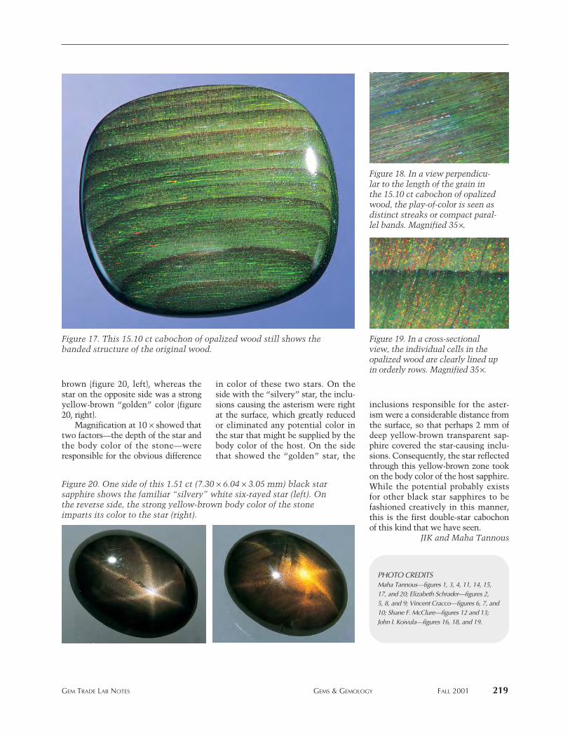
brown (figure 20, left), whereas thestar on the opposite side was a strongyellow-brown “golden” color (figure20, right).
Magnification at 10 ¥ showed thattwo factors—the depth of the star andthe body color of the stone—wereresponsible for the obvious difference
in color of these two stars. On theside with the “silvery” star, the inclu-sions causing the asterism were rightat the surface, which greatly reducedor eliminated any potential color inthe star that might be supplied by thebody color of the host. On the sidethat showed the “golden” star, the
inclusions responsible for the aster-ism were a considerable distance fromthe surface, so that perhaps 2 mm ofdeep yellow-brown transparent sap-phire covered the star-causing inclu-sions. Consequently, the star reflectedthrough this yellow-brown zone tookon the body color of the host sapphire.While the potential probably existsfor other black star sapphires to befashioned creatively in this manner,this is the first double-star cabochonof this kind that we have seen.
JIK and Maha Tannous
GEM TRADE LAB NOTES GEMS & GEMOLOGY FALL 2001 219
PHOTO CREDITSMaha Tannous—figures 1, 3, 4, 11, 14, 15,17, and 20; Elizabeth Schrader—figures 2,5, 8, and 9; Vincent Cracco—figures 6, 7, and10; Shane F. McClure—figures 12 and 13;John I. Koivula—figures 16, 18, and 19.
Figure 18. In a view perpendicu-lar to the length of the grain inthe 15.10 ct cabochon of opalizedwood, the play-of-color is seen asdistinct streaks or compact paral-lel bands. Magnified 35¥.
Figure 19. In a cross-sectionalview, the individual cells in theopalized wood are clearly lined upin orderly rows. Magnified 35¥.
Figure 17. This 15.10 ct cabochon of opalized wood still shows thebanded structure of the original wood.
Figure 20. One side of this 1.51 ct (7.30 ¥ 6.04 ¥ 3.05 mm) black starsapphire shows the familiar “silvery” white six-rayed star (left). Onthe reverse side, the strong yellow-brown body color of the stoneimparts its color to the star (right).
220 2000 Challenge Winners GEMS & GEMOLOGY Fall 2000
AUSTRALIA Coogee, Western Australia: Helen Haddy. Nedlands, Western Australia: Eleanor Sanders. Slacks Creek, Queensland: Ken Hunter� BELGIUM Diegem: Guy Lalous. Diksmuide: Honoré Loeters. Hemiksem: Daniel De Maeght. Overijse: Margrethe Gram-Jensen. Ruiselede:Lucette Nols � BRAZIL Rio de Janeiro: Luiz Angelo � CANADA Cowansville, Québec: Alain Deschamps. Kingston, Ontario: Brian Smith.
Oakville, Ontario: Alethea Simone Inns � CROATIA Zagreb: Sandra Crkvenac � CYPRUS Nicosia: George S. Stephanides � CZECH REPUBLIC Praha: Karel Mar
Úík � ENGLAND Tenteroen, Kent: Linda Bateley � FRANCE Paris: Stephen Perera
� GERMANY Amberg: Herbig Klaus. Idar-Oberstein: Josef Bogacz � HONG KONG Causeway Bay: Cristina O. Piercey � INDONESIA Ciputat, Jakarta: Warli Latumena � ITALY Ferrara: Sonia Franzolin. Porto Azzurro, Livorno: Diego Giuseppe Trainini.Valenza: Rossella Conti. Vicenza: Francesca Zen � LITHUANIA Vilnius: Saulius Fokas � NETHERLANDS Rotterdam: E. van Velzen.
Wassenaar: Jane M. Orsak � POLAND Lublin: Marek A. Prus � SCOTLAND Edinburgh: James W.M. Heatlie � SPAIN Burjassot, Valencia: Luis E. Ochando. Madrid: Shahrazad Krewi de Urquijo. Oviedo, Asturias: Consuelo Laspra. Playa P. Farnals, Valencia: Monika
Bergel-Becker. Port de Sóller, Baleares: J. Maurici Revilla Bonnin � SRI LANKA Gampaha: Nadee Abeykoon � THAILAND Conburi:Watcharaporu Keankeo � UNITED STATES Alabama Mobile: Lori Bryant. Arizona Tucson: David Arens. California Burlingame:
Sandra MacKenzie-Graham. Carlsbad: Marla Belbel, Carl Chilstrom, Michael T. Evans, Diane Flora, William J. Herberts, Mark S. Johnson, Cathy Jonathan, Jan Lombardi, Lynn L. Myers, Diane H. Saito, Abba R. Steinfeld, Richard Taylor, Philip G. York. Los Angeles:
Veronica Clark-Hudson. Marina Del Rey: Veronika Riedel. Pacifica: Diana L. Gamez. Penn Valley: Nancy Marie Spencer. Redwood City:Starla Turner. Santa Clarita: Beverly Nardoni-Kurz. Watsonville: Janet S. Mayou. Colorado Colorado Springs: Barbara Maffei.
Connecticut Simsbury: Jeffrey A. Adams. Florida Clearwater: Timothy D. Schuler. Deland: Sue Angevine Guess. Vero Beach: Lisa N. Perino.Georgia Buford: Lisa Hazan. Decatur: Ella Golden. Hawaii Makawao: Alison Fahland. Illinois Danvers: Anne Blumer, William Duff. Mokena:
Marianne Vander Zanden. Northbrook: Frank Pintz. Peoria: John Fitzgerald. Indiana Fishers: Laura D. Haas. Indianapolis: Mark Ferreira. Iowa West Des Moines: Frank Herman. Kansas Topeka: Ann Solcolofsky. Maine South Freeport: Arthur E. Spellissy, Jr. Maryland Darnestown:
Ron Suddendorf. Massachusetts Braintree: Alan R. Howarth. Brookline: Martin Haske. Lynnfield: John A. Caruso. Michigan Saginaw:Veronica Haldane. Mississippi Hattiesburg: A. Thomas Light. Missouri Perry: Bruce L. Elmer. Nevada Las Vegas: Deborah Helbling. Reno:
Terence E. Terras. New Jersey Fort Lee: Lioudmila Tretianova. New Mexico Santa Fe: Leon Weiner. New York City Island: Marjorie Kos. New York: John Kearney, Wendi M. Mayerson. Rye: Gregory J. Cunningham. North Carolina Creedmoor: Jennifer Jeffreys-Chen.
Manteo: Eileen Alexanian. Matthews: Terry A. Edwards. Ohio Athens: Colette M. Harrington. Cuyahoga Falls: Catherine S. Lee. Oregon Salem: Donald Lee Toney. Pennsylvania Schuylkill Haven: Janet L. Steinmetz. Yardley: Peter R. Stadelmeier.
Rhode Island Providence: Sarah A. Horst. Texas Austin: Judith Darnell, Anne Hawken. Corpus Christi: Warren A. Rees. Virginia Newport News: Sonia Brannan. Sterling: Donna B. Rios. Washington Poulsbo: Ruth Jorgensen. Seattle: Thomas C. Estervog.
Wisconsin Beaver Dam: Thomas G. Wendt. Milwaukee: William Bailey
Winners 2001This year, 285 dedicated readers participated in the
2001 Gems & Gemology Challenge. Entries arrived from all corners of the world, as readers tested their knowledge on the questions listed in the Spring
2001 issue. Those who earned a score of 75% or better received a GIAContinuing Education Certificate recognizing their achievement. The partici-
pants who scored a perfect 100% are listed below. Congratulations!
Challenge
Answers (See pp. 79–80 of the Spring 2001 issue for the questions):
(1) c, (2) b, (3) a, (4) c, (5) b, (6) a, (7) a, (8) d, (9) b, (10) c, (11) c, (12) a, (13) a, (14) c, (15) withdrawn, (16) d, (17) b, (18) d,
(19) a, (20) d, (21) b, (22) a, (23) a, (24) c, (25) c
220 CHALLENGE WINNERS GEMS & GEMOLOGY FALL 2001
222 GEM NEWS INTERNATIONAL GEMS & GEMOLOGY FALL 2001
EDITORBrendan M. Laurs ([email protected])
CONTRIBUTING EDITORSEmmanuel Fritsch, IMN, University of Nantes, France ([email protected])
Henry A. Hänni, SSEF, Basel, Switzerland([email protected])
Kenneth V. G. Scarratt, AGTA Gemological TestingCenter, New York ([email protected])
Karl Schmetzer, Petershausen, Germany
James E. Shigley, GIA Research,Carlsbad, California ([email protected])
Christopher P. Smith, Gübelin Gem Lab,Lucerne, Switzerland ([email protected])
GEM NEWS International
Conference. GNI editor Brendan Laurs attended the confer-ence and provided this report. The well-rounded programconsisted of approximately 40 presentations from miningand exploration company executives, mining engineers,government officials and diamond valuators, financial ana-lysts, and international financiers. Chaim Even-Zohar (edi-tor-in-chief and publisher, Mazal U’Bracha Diamonds andDiamond Intelligence Briefs) was the moderator of the con-ference, which focused mainly on Canadian diamond pro-duction, now and in the future.
In his introductory presentation, Mr. Even-Zoharstressed that the industry is in transition due to majorchanges in the diamond “pipeline” caused by the evolvingroles of the traditional major producers and the emergenceof new industry leaders (e.g., BHP-Billiton and Rio Tinto)in both mining and merchandising. He introduced thephrase committed rough for diamonds (mined orunmined) with a predetermined manufacturing destina-tion—such as, for example, the arrangement by Tiffany &Co. to receive diamonds from the forthcoming Diavikmine in Canada (figure 1). The recent restructuring of DeBeers is having a profound influence on the pipeline, asreduction of their diamond stockpile in 2000 contributedto the current overstocking in both the cutting centers andthe retail sector. Mr. Even-Zohar also explained the legalchallenges facing De Beers’s “supplier of choice” initiativeto create demand at the consumer level.
Martin Rapaport (Rapaport Diamond Report) echoedMr. Even-Zohar’s contention that the industry is undergo-ing fundamental, and irreversible, structural changes asthe result of a convergence of factors—in particular, aweak global economy, changes in De Beers, the brandingmovement, and “conflict” diamonds. He stressed that thefuture will hold greater market uncertainty in distributionand pricing, with rough prices determined by the prices ofpolished goods (a reversal of the situation in the past); con-sequently, rough-diamond producers must add valuethrough marketing. Diamond branding was a recurrent
Figure 1. These rough diamonds were recovered duringbulk sampling and evaluation of the A-154S pipe at theDiavik mine. Tiffany & Co. has already arranged topurchase some of the diamond production from thismine. Photo courtesy of Diavik Diamond Mines Inc.
DIAMONDS Report from the 2nd World Diamond Conference,Vancouver. On August 22 and 23, 2001, approximately 400participants from 29 countries converged in Vancouver,British Columbia, Canada for the 2nd World Diamond
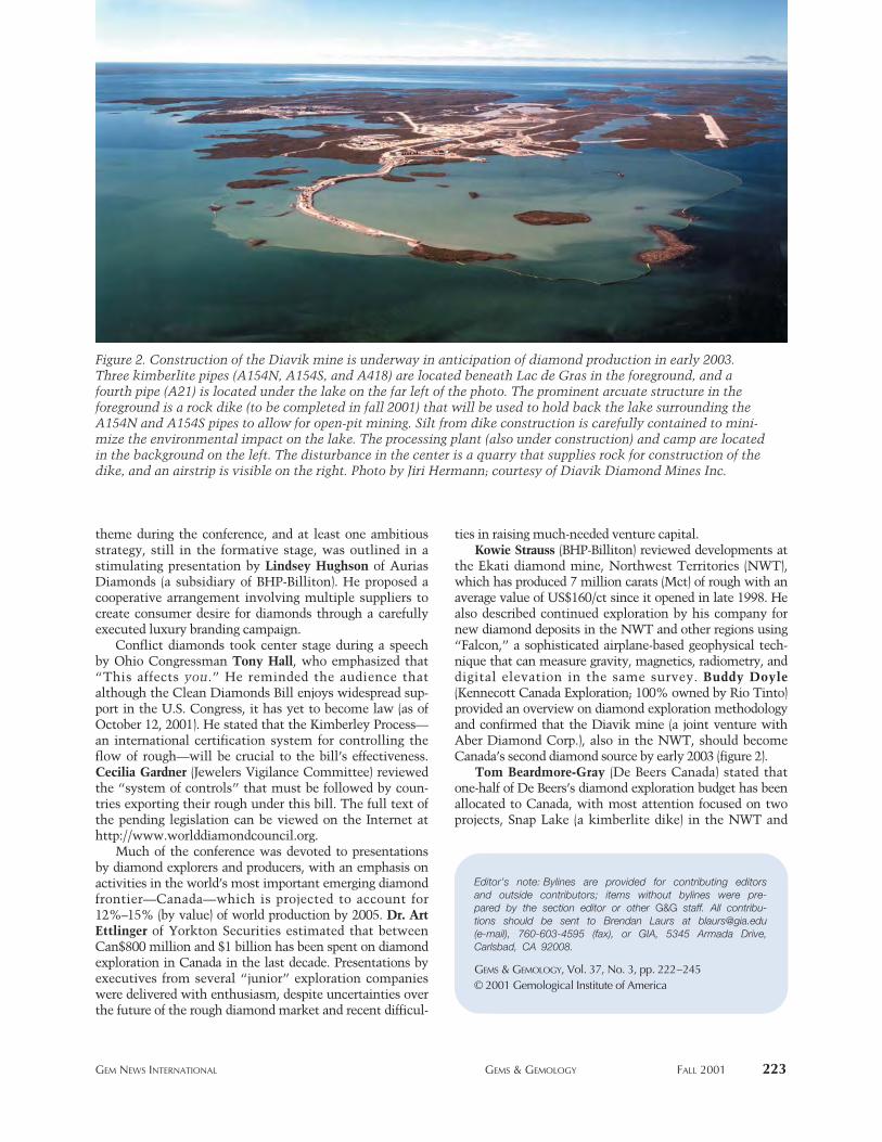
theme during the conference, and at least one ambitiousstrategy, still in the formative stage, was outlined in astimulating presentation by Lindsey Hughson of AuriasDiamonds (a subsidiary of BHP-Billiton). He proposed acooperative arrangement involving multiple suppliers tocreate consumer desire for diamonds through a carefullyexecuted luxury branding campaign.
Conflict diamonds took center stage during a speechby Ohio Congressman Tony Hall, who emphasized that“This affects you.” He reminded the audience thatalthough the Clean Diamonds Bill enjoys widespread sup-port in the U.S. Congress, it has yet to become law (as ofOctober 12, 2001). He stated that the Kimberley Process—an international certification system for controlling theflow of rough—will be crucial to the bill’s effectiveness.Cecilia Gardner (Jewelers Vigilance Committee) reviewedthe “system of controls” that must be followed by coun-tries exporting their rough under this bill. The full text ofthe pending legislation can be viewed on the Internet athttp://www.worlddiamondcouncil.org.
Much of the conference was devoted to presentationsby diamond explorers and producers, with an emphasis onactivities in the world’s most important emerging diamondfrontier—Canada—which is projected to account for12%–15% (by value) of world production by 2005. Dr. ArtEttlinger of Yorkton Securities estimated that betweenCan$800 million and $1 billion has been spent on diamondexploration in Canada in the last decade. Presentations byexecutives from several “junior” exploration companieswere delivered with enthusiasm, despite uncertainties overthe future of the rough diamond market and recent difficul-
ties in raising much-needed venture capital. Kowie Strauss (BHP-Billiton) reviewed developments at
the Ekati diamond mine, Northwest Territories (NWT),which has produced 7 million carats (Mct) of rough with anaverage value of US$160/ct since it opened in late 1998. Healso described continued exploration by his company fornew diamond deposits in the NWT and other regions using“Falcon,” a sophisticated airplane-based geophysical tech-nique that can measure gravity, magnetics, radiometry, anddigital elevation in the same survey. Buddy Doyle(Kennecott Canada Exploration; 100% owned by Rio Tinto)provided an overview on diamond exploration methodologyand confirmed that the Diavik mine (a joint venture withAber Diamond Corp.), also in the NWT, should becomeCanada’s second diamond source by early 2003 (figure 2).
Tom Beardmore-Gray (De Beers Canada) stated thatone-half of De Beers’s diamond exploration budget has beenallocated to Canada, with most attention focused on twoprojects, Snap Lake (a kimberlite dike) in the NWT and
GEM NEWS INTERNATIONAL GEMS & GEMOLOGY FALL 2001 223
Editor’s note: Bylines are provided for contributing editors and outside contributors; items without bylines were pre-pared by the section editor or other G&G staff. All contribu-tions should be sent to Brendan Laurs at [email protected] (e-mail), 760-603-4595 (fax), or GIA, 5345 Armada Drive,Carlsbad, CA 92008.
GEMS & GEMOLOGY, Vol. 37, No. 3, pp. 222–245© 2001 Gemological Institute of America
Figure 2. Construction of the Diavik mine is underway in anticipation of diamond production in early 2003.Three kimberlite pipes (A154N, A154S, and A418) are located beneath Lac de Gras in the foreground, and afourth pipe (A21) is located under the lake on the far left of the photo. The prominent arcuate structure in theforeground is a rock dike (to be completed in fall 2001) that will be used to hold back the lake surrounding theA154N and A154S pipes to allow for open-pit mining. Silt from dike construction is carefully contained to mini-mize the environmental impact on the lake. The processing plant (also under construction) and camp are locatedin the background on the left. The disturbance in the center is a quarry that supplies rock for construction of thedike, and an airstrip is visible on the right. Photo by Jiri Hermann; courtesy of Diavik Diamond Mines Inc.
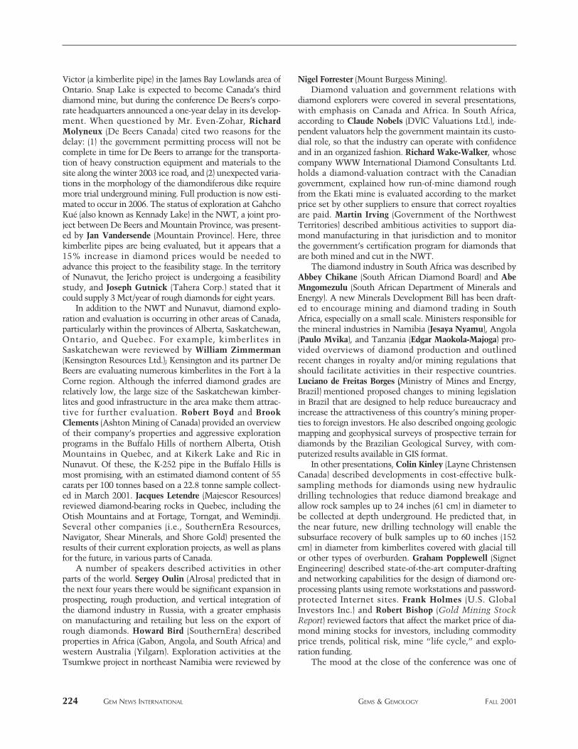
Victor (a kimberlite pipe) in the James Bay Lowlands area ofOntario. Snap Lake is expected to become Canada’s thirddiamond mine, but during the conference De Beers’s corpo-rate headquarters announced a one-year delay in its develop-ment. When questioned by Mr. Even-Zohar, RichardMolyneux (De Beers Canada) cited two reasons for thedelay: (1) the government permitting process will not becomplete in time for De Beers to arrange for the transporta-tion of heavy construction equipment and materials to thesite along the winter 2003 ice road, and (2) unexpected varia-tions in the morphology of the diamondiferous dike requiremore trial underground mining. Full production is now esti-mated to occur in 2006. The status of exploration at GahchoKué (also known as Kennady Lake) in the NWT, a joint pro-ject between De Beers and Mountain Province, was present-ed by Jan Vandersende (Mountain Province). Here, threekimberlite pipes are being evaluated, but it appears that a15% increase in diamond prices would be needed toadvance this project to the feasibility stage. In the territoryof Nunavut, the Jericho project is undergoing a feasibilitystudy, and Joseph Gutnick (Tahera Corp.) stated that itcould supply 3 Mct/year of rough diamonds for eight years.
In addition to the NWT and Nunavut, diamond explo-ration and evaluation is occurring in other areas of Canada,particularly within the provinces of Alberta, Saskatchewan,Ontario, and Quebec. For example, kimberlites inSaskatchewan were reviewed by William Zimmerman(Kensington Resources Ltd.); Kensington and its partner DeBeers are evaluating numerous kimberlites in the Fort à laCorne region. Although the inferred diamond grades arerelatively low, the large size of the Saskatchewan kimber-lites and good infrastructure in the area make them attrac-tive for further evaluation. Robert Boyd and BrookClements (Ashton Mining of Canada) provided an overviewof their company’s properties and aggressive explorationprograms in the Buffalo Hills of northern Alberta, OtishMountains in Quebec, and at Kikerk Lake and Ric inNunavut. Of these, the K-252 pipe in the Buffalo Hills ismost promising, with an estimated diamond content of 55carats per 100 tonnes based on a 22.8 tonne sample collect-ed in March 2001. Jacques Letendre (Majescor Resources)reviewed diamond-bearing rocks in Quebec, including theOtish Mountains and at Fortage, Torngat, and Wemindji.Several other companies (i.e., SouthernEra Resources,Navigator, Shear Minerals, and Shore Gold) presented theresults of their current exploration projects, as well as plansfor the future, in various parts of Canada.
A number of speakers described activities in otherparts of the world. Sergey Oulin (Alrosa) predicted that inthe next four years there would be significant expansion inprospecting, rough production, and vertical integration ofthe diamond industry in Russia, with a greater emphasison manufacturing and retailing but less on the export ofrough diamonds. Howard Bird (SouthernEra) describedproperties in Africa (Gabon, Angola, and South Africa) andwestern Australia (Yilgarn). Exploration activities at theTsumkwe project in northeast Namibia were reviewed by
Nigel Forrester (Mount Burgess Mining).Diamond valuation and government relations with
diamond explorers were covered in several presentations,with emphasis on Canada and Africa. In South Africa,according to Claude Nobels (DVIC Valuations Ltd.), inde-pendent valuators help the government maintain its custo-dial role, so that the industry can operate with confidenceand in an organized fashion. Richard Wake-Walker, whosecompany WWW International Diamond Consultants Ltd.holds a diamond-valuation contract with the Canadiangovernment, explained how run-of-mine diamond roughfrom the Ekati mine is evaluated according to the marketprice set by other suppliers to ensure that correct royaltiesare paid. Martin Irving (Government of the NorthwestTerritories) described ambitious activities to support dia-mond manufacturing in that jurisdiction and to monitorthe government’s certification program for diamonds thatare both mined and cut in the NWT.
The diamond industry in South Africa was described byAbbey Chikane (South African Diamond Board) and AbeMngomezulu (South African Department of Minerals andEnergy). A new Minerals Development Bill has been draft-ed to encourage mining and diamond trading in SouthAfrica, especially on a small scale. Ministers responsible forthe mineral industries in Namibia (Jesaya Nyamu), Angola(Paulo Mvika), and Tanzania (Edgar Maokola-Majoga) pro-vided overviews of diamond production and outlinedrecent changes in royalty and/or mining regulations thatshould facilitate activities in their respective countries.Luciano de Freitas Borges (Ministry of Mines and Energy,Brazil) mentioned proposed changes to mining legislationin Brazil that are designed to help reduce bureaucracy andincrease the attractiveness of this country’s mining proper-ties to foreign investors. He also described ongoing geologicmapping and geophysical surveys of prospective terrain fordiamonds by the Brazilian Geological Survey, with com-puterized results available in GIS format.
In other presentations, Colin Kinley (Layne ChristensenCanada) described developments in cost-effective bulk-sampling methods for diamonds using new hydraulicdrilling technologies that reduce diamond breakage andallow rock samples up to 24 inches (61 cm) in diameter tobe collected at depth underground. He predicted that, inthe near future, new drilling technology will enable thesubsurface recovery of bulk samples up to 60 inches (152cm) in diameter from kimberlites covered with glacial tillor other types of overburden. Graham Popplewell (SignetEngineering) described state-of-the-art computer-draftingand networking capabilities for the design of diamond ore-processing plants using remote workstations and password-protected Internet sites. Frank Holmes (U.S. GlobalInvestors Inc.) and Robert Bishop (Gold Mining StockReport) reviewed factors that affect the market price of dia-mond mining stocks for investors, including commodityprice trends, political risk, mine “life cycle,” and explo-ration funding.
The mood at the close of the conference was one of
224 GEM NEWS INTERNATIONAL GEMS & GEMOLOGY FALL 2001
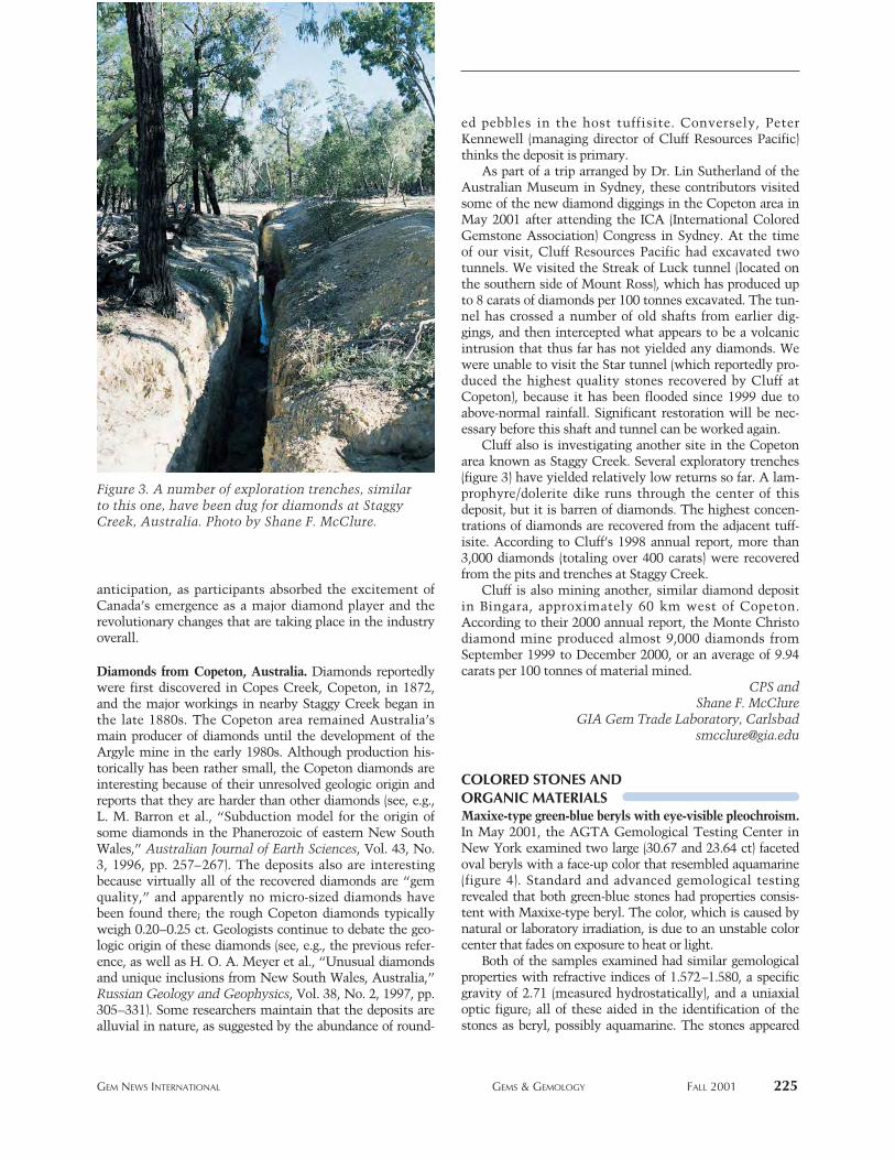
anticipation, as participants absorbed the excitement ofCanada’s emergence as a major diamond player and therevolutionary changes that are taking place in the industryoverall.
Diamonds from Copeton, Australia. Diamonds reportedlywere first discovered in Copes Creek, Copeton, in 1872,and the major workings in nearby Staggy Creek began inthe late 1880s. The Copeton area remained Australia’smain producer of diamonds until the development of theArgyle mine in the early 1980s. Although production his-torically has been rather small, the Copeton diamonds areinteresting because of their unresolved geologic origin andreports that they are harder than other diamonds (see, e.g.,L. M. Barron et al., “Subduction model for the origin ofsome diamonds in the Phanerozoic of eastern New SouthWales,” Australian Journal of Earth Sciences, Vol. 43, No.3, 1996, pp. 257–267). The deposits also are interestingbecause virtually all of the recovered diamonds are “gemquality,” and apparently no micro-sized diamonds havebeen found there; the rough Copeton diamonds typicallyweigh 0.20–0.25 ct. Geologists continue to debate the geo-logic origin of these diamonds (see, e.g., the previous refer-ence, as well as H. O. A. Meyer et al., “Unusual diamondsand unique inclusions from New South Wales, Australia,”Russian Geology and Geophysics, Vol. 38, No. 2, 1997, pp.305–331). Some researchers maintain that the deposits arealluvial in nature, as suggested by the abundance of round-
ed pebbles in the host tuffisite. Conversely, PeterKennewell (managing director of Cluff Resources Pacific)thinks the deposit is primary.
As part of a trip arranged by Dr. Lin Sutherland of theAustralian Museum in Sydney, these contributors visitedsome of the new diamond diggings in the Copeton area inMay 2001 after attending the ICA (International ColoredGemstone Association) Congress in Sydney. At the timeof our visit, Cluff Resources Pacific had excavated twotunnels. We visited the Streak of Luck tunnel (located onthe southern side of Mount Ross), which has produced upto 8 carats of diamonds per 100 tonnes excavated. The tun-nel has crossed a number of old shafts from earlier dig-gings, and then intercepted what appears to be a volcanicintrusion that thus far has not yielded any diamonds. Wewere unable to visit the Star tunnel (which reportedly pro-duced the highest quality stones recovered by Cluff atCopeton), because it has been flooded since 1999 due toabove-normal rainfall. Significant restoration will be nec-essary before this shaft and tunnel can be worked again.
Cluff also is investigating another site in the Copetonarea known as Staggy Creek. Several exploratory trenches(figure 3) have yielded relatively low returns so far. A lam-prophyre/dolerite dike runs through the center of thisdeposit, but it is barren of diamonds. The highest concen-trations of diamonds are recovered from the adjacent tuff-isite. According to Cluff’s 1998 annual report, more than3,000 diamonds (totaling over 400 carats) were recoveredfrom the pits and trenches at Staggy Creek.
Cluff is also mining another, similar diamond depositin Bingara, approximately 60 km west of Copeton.According to their 2000 annual report, the Monte Christodiamond mine produced almost 9,000 diamonds fromSeptember 1999 to December 2000, or an average of 9.94carats per 100 tonnes of material mined.
CPS andShane F. McClure
GIA Gem Trade Laboratory, [email protected]
COLORED STONES AND ORGANIC MATERIALSMaxixe-type green-blue beryls with eye-visible pleochroism.In May 2001, the AGTA Gemological Testing Center inNew York examined two large (30.67 and 23.64 ct) facetedoval beryls with a face-up color that resembled aquamarine(figure 4). Standard and advanced gemological testingrevealed that both green-blue stones had properties consis-tent with Maxixe-type beryl. The color, which is caused bynatural or laboratory irradiation, is due to an unstable colorcenter that fades on exposure to heat or light.
Both of the samples examined had similar gemologicalproperties with refractive indices of 1.572–1.580, a specificgravity of 2.71 (measured hydrostatically), and a uniaxialoptic figure; all of these aided in the identification of thestones as beryl, possibly aquamarine. The stones appeared
GEM NEWS INTERNATIONAL GEMS & GEMOLOGY FALL 2001 225
Figure 3. A number of exploration trenches, similarto this one, have been dug for diamonds at StaggyCreek, Australia. Photo by Shane F. McClure.
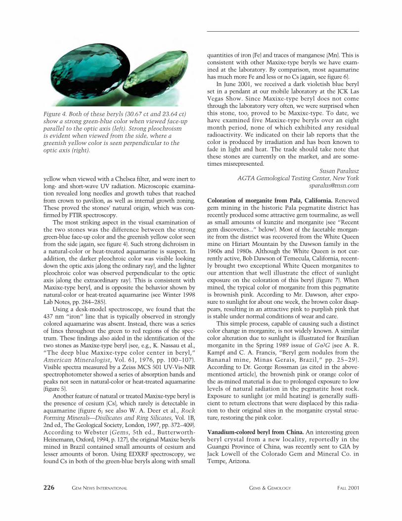
yellow when viewed with a Chelsea filter, and were inert tolong- and short-wave UV radiation. Microscopic examina-tion revealed long needles and growth tubes that reachedfrom crown to pavilion, as well as internal growth zoning.These proved the stones’ natural origin, which was con-firmed by FTIR spectroscopy.
The most striking aspect in the visual examination ofthe two stones was the difference between the stronggreen-blue face-up color and the greenish yellow color seenfrom the side (again, see figure 4). Such strong dichroism ina natural-color or heat-treated aquamarine is suspect. Inaddition, the darker pleochroic color was visible lookingdown the optic axis (along the ordinary ray), and the lighterpleochroic color was observed perpendicular to the opticaxis (along the extraordinary ray). This is consistent withMaxixe-type beryl, and is opposite the behavior shown bynatural-color or heat-treated aquamarine (see Winter 1998Lab Notes, pp. 284–285).
Using a desk-model spectroscope, we found that the437 nm “iron” line that is typically observed in stronglycolored aquamarine was absent. Instead, there was a seriesof lines throughout the green to red regions of the spec-trum. These findings also aided in the identification of thetwo stones as Maxixe-type beryl (see, e.g., K. Nassau et al.,“The deep blue Maxixe-type color center in beryl,”American Mineralogist, Vol. 61, 1976, pp. 100–107).Visible spectra measured by a Zeiss MCS 501 UV-Vis-NIRspectrophotometer showed a series of absorption bands andpeaks not seen in natural-color or heat-treated aquamarine(figure 5).
Another feature of natural or treated Maxixe-type beryl isthe presence of cesium (Cs), which rarely is detectable inaquamarine (figure 6; see also W. A. Deer et al., RockForming Minerals—Disilicates and Ring Silicates, Vol. 1B,2nd ed., The Geological Society, London, 1997, pp. 372–409).According to Webster (Gems, 5th ed., Butterworth-Heinemann, Oxford, 1994, p. 127), the original Maxixe berylsmined in Brazil contained small amounts of cesium andlesser amounts of boron. Using EDXRF spectroscopy, wefound Cs in both of the green-blue beryls along with small
quantities of iron (Fe) and traces of manganese (Mn). This isconsistent with other Maxixe-type beryls we have exam-ined at the laboratory. By comparison, most aquamarinehas much more Fe and less or no Cs (again, see figure 6).
In June 2001, we received a dark violetish blue berylset in a pendant at our mobile laboratory at the JCK LasVegas Show. Since Maxixe-type beryl does not comethrough the laboratory very often, we were surprised whenthis stone, too, proved to be Maxixe-type. To date, wehave examined five Maxixe-type beryls over an eightmonth period, none of which exhibited any residualradioactivity. We indicated on their lab reports that thecolor is produced by irradiation and has been known tofade in light and heat. The trade should take note thatthese stones are currently on the market, and are some-times misrepresented.
Susan ParaluszAGTA Gemological Testing Center, New York
Coloration of morganite from Pala, California. Renewedgem mining in the historic Pala pegmatite district hasrecently produced some attractive gem tourmaline, as wellas small amounts of kunzite and morganite (see “Recentgem discoveries...” below). Most of the facetable morgan-ite from the district was recovered from the White Queenmine on Hiriart Mountain by the Dawson family in the1960s and 1980s. Although the White Queen is not cur-rently active, Bob Dawson of Temecula, California, recent-ly brought two exceptional White Queen morganites toour attention that well illustrate the effect of sunlightexposure on the coloration of this beryl (figure 7). Whenmined, the typical color of morganite from this pegmatiteis brownish pink. According to Mr. Dawson, after expo-sure to sunlight for about one week, the brown color disap-pears, resulting in an attractive pink to purplish pink thatis stable under normal conditions of wear and care.
This simple process, capable of causing such a distinctcolor change in morganite, is not widely known. A similarcolor alteration due to sunlight is illustrated for Brazilianmorganite in the Spring 1989 issue of G&G (see A. R.Kampf and C. A. Francis, “Beryl gem nodules from theBananal mine, Minas Gerais, Brazil,” pp. 25–29).According to Dr. George Rossman (as cited in the above-mentioned article), the brownish pink or orange color ofthe as-mined material is due to prolonged exposure to lowlevels of natural radiation in the pegmatite host rock.Exposure to sunlight (or mild heating) is generally suffi-cient to return electrons that were displaced by this radia-tion to their original sites in the morganite crystal struc-ture, restoring the pink color.
Vanadium-colored beryl from China. An interesting greenberyl crystal from a new locality, reportedly in theGuangxi Province of China, was recently sent to GIA byJack Lowell of the Colorado Gem and Mineral Co. inTempe, Arizona.
226 GEM NEWS INTERNATIONAL GEMS & GEMOLOGY FALL 2001
Figure 4. Both of these beryls (30.67 ct and 23.64 ct)show a strong green-blue color when viewed face-upparallel to the optic axis (left). Strong pleochroismis evident when viewed from the side, where agreenish yellow color is seen perpendicular to theoptic axis (right).
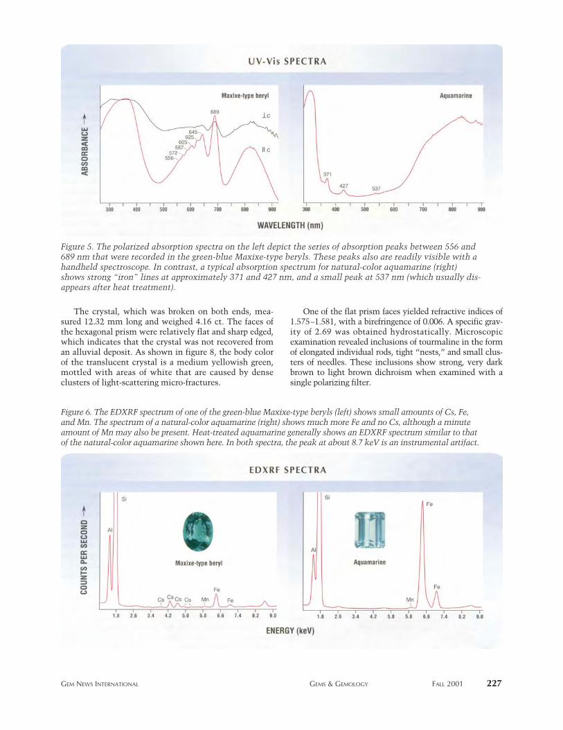
The crystal, which was broken on both ends, mea-sured 12.32 mm long and weighed 4.16 ct. The faces ofthe hexagonal prism were relatively flat and sharp edged,which indicates that the crystal was not recovered froman alluvial deposit. As shown in figure 8, the body colorof the translucent crystal is a medium yellowish green,mottled with areas of white that are caused by denseclusters of light-scattering micro-fractures.
One of the flat prism faces yielded refractive indices of1.575–1.581, with a birefringence of 0.006. A specific grav-ity of 2.69 was obtained hydrostatically. Microscopicexamination revealed inclusions of tourmaline in the formof elongated individual rods, tight “nests,” and small clus-ters of needles. These inclusions show strong, very darkbrown to light brown dichroism when examined with asingle polarizing filter.
GEM NEWS INTERNATIONAL GEMS & GEMOLOGY FALL 2001 227
Figure 6. The EDXRF spectrum of one of the green-blue Maxixe-type beryls (left) shows small amounts of Cs, Fe,and Mn. The spectrum of a natural-color aquamarine (right) shows much more Fe and no Cs, although a minuteamount of Mn may also be present. Heat-treated aquamarine generally shows an EDXRF spectrum similar to thatof the natural-color aquamarine shown here. In both spectra, the peak at about 8.7 keV is an instrumental artifact.
Figure 5. The polarized absorption spectra on the left depict the series of absorption peaks between 556 and689 nm that were recorded in the green-blue Maxixe-type beryls. These peaks also are readily visible with ahandheld spectroscope. In contrast, a typical absorption spectrum for natural-color aquamarine (right)shows strong “iron” lines at approximately 371 and 427 nm, and a small peak at 537 nm (which usually dis-appears after heat treatment).

The crystal was inert to both long- and short-wave UVradiation and showed no useful spectral features otherthan a moderate general absorption of the blue regionwhen examined with a desk-model spectroscope. Whenthe crystal was examined in transmitted light with aChelsea filter, it took on the color of the filter itself, andno red transmission was observed.
EDXRF analysis revealed only the presence of vanadi-um and iron. No chromium was detected. The yellowishgreen body color of this crystal suggests that vanadium,and not iron, is the primary coloring agent, although thepossible influence of iron cannot be ruled out. It is inter-esting to note that another relatively new locality for vana-dium-bearing green beryl (which also contains somechromium) has been reported in China, in YunnanProvince (see F. Hongbin and L. Yongxian, “Mineralogicalcharacteristics and exploitation perspective of emeralds inYunnan Province,” Mineral Resources and Geology, Vol.12, No. 3, 1998, pp. 188–192).
Thus far most of the material recovered has been soldas “emerald” mineral specimens. According to Mr.Lowell, a few gems have been fashioned from these crys-tals, but they have been marketed only in China.
John I. Koivula, Maha Tannous,and Sam Muhlmeister
GIA Gem Trade Laboratory, [email protected]
Mini-faults in chalcedony. Disquieting earthquakes andspectacular volcanoes generally serve to remind us of thepowerful and potentially destructive forces of nature.Even though these mega-forces may play a role in certaingem-forming processes, we rarely see any obvious evi-dence of their effect in the miniature world of gems. Withthis in mind, it was interesting to examine two polishedslabs of patterned jasper (a variety of chalcedony) thatshowed sharp displacements in their layering (see, e.g.,figure 9).
The two colorful samples were purchased at the 2001Tucson show from West Coast Mining, College Place,Washington. The jasper samples were said to originatefrom Mexico (more specific locality unknown). We hadthem recut for photography by Leon Agee, of Deer Park,Washington, to 56.41 ct (31.98 ¥ 30.59 ¥ 5.24 mm) and3.98 ct (12.00 ¥ 11.39 ¥ 2.24 mm).
Once the specimens were recut, the bedding planesand their displacement across miniature faults were evenmore apparent (figures 9 and 10). Standard gemologicaltesting and observation confirmed their identification asjasper. John I. Koivula and Maha Tannous
Recent gem discoveries in Pala, California. Granitic peg-matites in the Pala district are once again yielding signifi-cant finds of tourmaline, kunzite, and other gems. In theearly 1900s, mines in Pala and the nearby Mesa Grande dis-trict (particularly the Himalaya mine, located 30 km south-east of the town of Pala) made Southern California a world-
228 GEM NEWS INTERNATIONAL GEMS & GEMOLOGY FALL 2001
Figure 7. The 191.59 ct stone on the left shows thebrownish pink color that is typical of morganite as
it is mined from the White Queen mine in Pala,California. After exposure to sunlight for about
one week, the brown color disappears, as shownin the 202.41 ct purplish pink White Queen mor-
ganite on the right. Courtesy of Bob Dawson;photo © Harold & Erica Van Pelt.
Figure 8. This 4.16 ct vanadium-colored beryl crystal reportedly was recovered from China’sGuangxi Province. Photo by Maha Tannous.
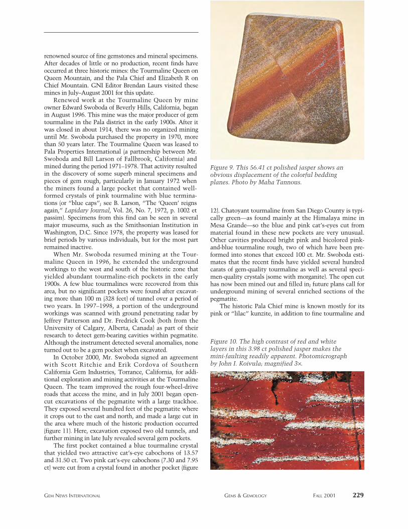
renowned source of fine gemstones and mineral specimens.After decades of little or no production, recent finds haveoccurred at three historic mines: the Tourmaline Queen onQueen Mountain, and the Pala Chief and Elizabeth R onChief Mountain. GNI Editor Brendan Laurs visited thesemines in July–August 2001 for this update.
Renewed work at the Tourmaline Queen by mineowner Edward Swoboda of Beverly Hills, California, beganin August 1996. This mine was the major producer of gemtourmaline in the Pala district in the early 1900s. After itwas closed in about 1914, there was no organized mininguntil Mr. Swoboda purchased the property in 1970, morethan 50 years later. The Tourmaline Queen was leased toPala Properties International (a partnership between Mr.Swoboda and Bill Larson of Fallbrook, California) andmined during the period 1971–1978. That activity resultedin the discovery of some superb mineral specimens andpieces of gem rough, particularly in January 1972 whenthe miners found a large pocket that contained well-formed crystals of pink tourmaline with blue termina-tions (or “blue caps”; see B. Larson, “The ‘Queen’ reignsagain,” Lapidary Journal, Vol. 26, No. 7, 1972, p. 1002 etpassim). Specimens from this find can be seen in severalmajor museums, such as the Smithsonian Institution inWashington, D.C. Since 1978, the property was leased forbrief periods by various individuals, but for the most partremained inactive.
When Mr. Swoboda resumed mining at the Tour-maline Queen in 1996, he extended the undergroundworkings to the west and south of the historic zone thatyielded abundant tourmaline-rich pockets in the early1900s. A few blue tourmalines were recovered from thisarea, but no significant pockets were found after excavat-ing more than 100 m (328 feet) of tunnel over a period oftwo years. In 1997–1998, a portion of the undergroundworkings was scanned with ground penetrating radar byJeffrey Patterson and Dr. Fredrick Cook (both from theUniversity of Calgary, Alberta, Canada) as part of theirresearch to detect gem-bearing cavities within pegmatite.Although the instrument detected several anomalies, noneturned out to be a gem pocket when excavated.
In October 2000, Mr. Swoboda signed an agreementwith Scott Ritchie and Erik Cordova of SouthernCalifornia Gem Industries, Torrance, California, for addi-tional exploration and mining activities at the TourmalineQueen. The team improved the rough four-wheel-driveroads that access the mine, and in July 2001 began open-cut excavations of the pegmatite with a large trackhoe.They exposed several hundred feet of the pegmatite whereit crops out to the east and north, and made a large cut inthe area where much of the historic production occurred(figure 11). Here, excavation exposed two old tunnels, andfurther mining in late July revealed several gem pockets.
The first pocket contained a blue tourmaline crystalthat yielded two attractive cat’s-eye cabochons of 13.57and 31.50 ct. Two pink cat’s-eye cabochons (7.30 and 7.95ct) were cut from a crystal found in another pocket (figure
12). Chatoyant tourmaline from San Diego County is typi-cally green—as found mainly at the Himalaya mine inMesa Grande—so the blue and pink cat’s-eyes cut frommaterial found in these new pockets are very unusual.Other cavities produced bright pink and bicolored pink-and-blue tourmaline rough, two of which have been pre-formed into stones that exceed 100 ct. Mr. Swoboda esti-mates that the recent finds have yielded several hundredcarats of gem-quality tourmaline as well as several speci-men-quality crystals (some with morganite). The open cuthas now been mined out and filled in; future plans call forunderground mining of several enriched sections of thepegmatite.
The historic Pala Chief mine is known mostly for itspink or “lilac” kunzite, in addition to fine tourmaline and
GEM NEWS INTERNATIONAL GEMS & GEMOLOGY FALL 2001 229
Figure 10. The high contrast of red and white layers in this 3.98 ct polished jasper makes themini-faulting readily apparent. Photomicrographby John I. Koivula; magnified 3¥.
Figure 9. This 56.41 ct polished jasper shows anobvious displacement of the colorful beddingplanes. Photo by Maha Tannous.
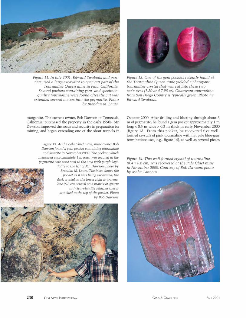
morganite. The current owner, Bob Dawson of Temecula,California, purchased the property in the early 1990s. Mr.Dawson improved the roads and security in preparation formining, and began extending one of the short tunnels in
October 2000. After drilling and blasting through about 3m of pegmatite, he found a gem pocket approximately 1 mlong ¥ 0.5 m wide ¥ 0.3 m thick in early November 2000(figure 13). From this pocket, he recovered five well-formed crystals of pink tourmaline with flat pale blue-grayterminations (see, e.g., figure 14), as well as several pieces
230 GEM NEWS INTERNATIONAL GEMS & GEMOLOGY FALL 2001
Figure 13. At the Pala Chief mine, mine owner BobDawson found a gem pocket containing tourmaline and kunzite in November 2000. The pocket, which
measured approximately 1 m long, was located in the pegmatite core zone next to the area with purple lepi-
dolite to the left of Mr. Dawson; photo byBrendan M. Laurs. The inset shows the
pocket as it was being excavated; the dark crystal on the lower right is tourma-line (6.3 cm across) on a matrix of quartz
and cleavelandite feldspar that is attached to the top of the pocket. Photo
by Bob Dawson.
Figure 14. This well-formed crystal of tourmaline(8.4 ¥ 6.2 cm) was recovered at the Pala Chief minein November 2000. Courtesy of Bob Dawson; photoby Maha Tannous.
Figure 11. In July 2001, Edward Swoboda and part-ners used a large excavator to open-cut part of the
Tourmaline Queen mine in Pala, California.Several pockets containing gem- and specimen-
quality tourmaline were found after the cut wasextended several meters into the pegmatite. Photo
by Brendan M. Laurs.
Figure 12. One of the gem pockets recently found atthe Tourmaline Queen mine yielded a chatoyanttourmaline crystal that was cut into these twocat’s-eyes (7.30 and 7.95 ct). Chatoyant tourmalinefrom San Diego County is typically green. Photo byEdward Swoboda.
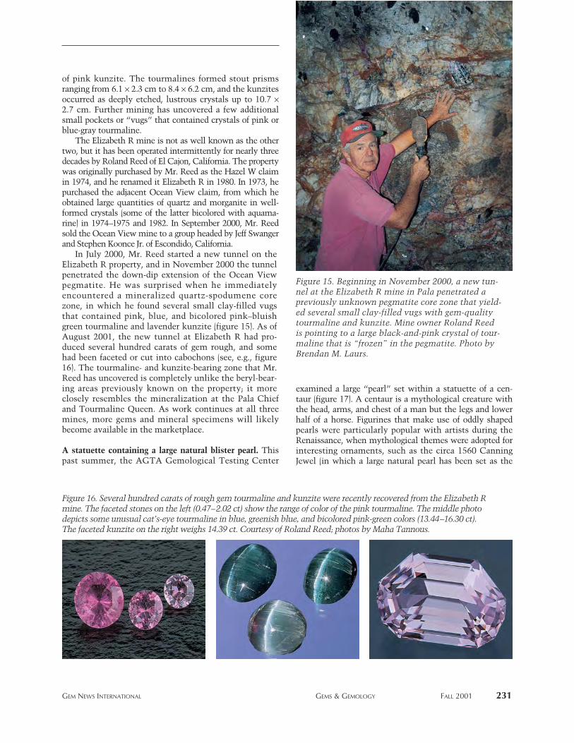
of pink kunzite. The tourmalines formed stout prismsranging from 6.1 ¥ 2.3 cm to 8.4 ¥ 6.2 cm, and the kunzitesoccurred as deeply etched, lustrous crystals up to 10.7 ¥2.7 cm. Further mining has uncovered a few additionalsmall pockets or “vugs” that contained crystals of pink orblue-gray tourmaline.
The Elizabeth R mine is not as well known as the othertwo, but it has been operated intermittently for nearly threedecades by Roland Reed of El Cajon, California. The propertywas originally purchased by Mr. Reed as the Hazel W claimin 1974, and he renamed it Elizabeth R in 1980. In 1973, hepurchased the adjacent Ocean View claim, from which heobtained large quantities of quartz and morganite in well-formed crystals (some of the latter bicolored with aquama-rine) in 1974–1975 and 1982. In September 2000, Mr. Reedsold the Ocean View mine to a group headed by Jeff Swangerand Stephen Koonce Jr. of Escondido, California.
In July 2000, Mr. Reed started a new tunnel on theElizabeth R property, and in November 2000 the tunnelpenetrated the down-dip extension of the Ocean Viewpegmatite. He was surprised when he immediatelyencountered a mineralized quartz-spodumene corezone, in which he found several small clay-filled vugsthat contained pink, blue, and bicolored pink–bluishgreen tourmaline and lavender kunzite (figure 15). As ofAugust 2001, the new tunnel at Elizabeth R had pro-duced several hundred carats of gem rough, and somehad been faceted or cut into cabochons (see, e.g., figure16). The tourmaline- and kunzite-bearing zone that Mr.Reed has uncovered is completely unlike the beryl-bear-ing areas previously known on the property; it moreclosely resembles the mineralization at the Pala Chiefand Tourmaline Queen. As work continues at all threemines, more gems and mineral specimens will likelybecome available in the marketplace.
A statuette containing a large natural blister pearl. Thispast summer, the AGTA Gemological Testing Center
examined a large “pearl” set within a statuette of a cen-taur (figure 17). A centaur is a mythological creature withthe head, arms, and chest of a man but the legs and lowerhalf of a horse. Figurines that make use of oddly shapedpearls were particularly popular with artists during theRenaissance, when mythological themes were adopted forinteresting ornaments, such as the circa 1560 CanningJewel (in which a large natural pearl has been set as the
GEM NEWS INTERNATIONAL GEMS & GEMOLOGY FALL 2001 231
Figure 16. Several hundred carats of rough gem tourmaline and kunzite were recently recovered from the Elizabeth Rmine. The faceted stones on the left (0.47–2.02 ct) show the range of color of the pink tourmaline. The middle photodepicts some unusual cat’s-eye tourmaline in blue, greenish blue, and bicolored pink-green colors (13.44–16.30 ct).The faceted kunzite on the right weighs 14.39 ct. Courtesy of Roland Reed; photos by Maha Tannous.
Figure 15. Beginning in November 2000, a new tun-nel at the Elizabeth R mine in Pala penetrated apreviously unknown pegmatite core zone that yield-ed several small clay-filled vugs with gem-qualitytourmaline and kunzite. Mine owner Roland Reedis pointing to a large black-and-pink crystal of tour-maline that is “frozen” in the pegmatite. Photo byBrendan M. Laurs.
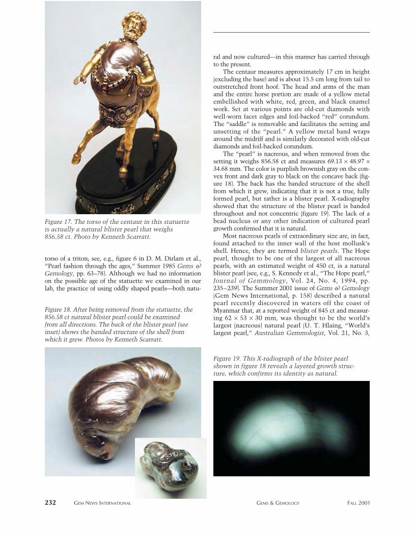
torso of a triton; see, e.g., figure 6 in D. M. Dirlam et al.,“Pearl fashion through the ages,” Summer 1985 Gems &Gemology, pp. 63–78). Although we had no informationon the possible age of the statuette we examined in ourlab, the practice of using oddly shaped pearls—both natu-
ral and now cultured—in this manner has carried throughto the present.
The centaur measures approximately 17 cm in height(excluding the base) and is about 15.5 cm long from tail tooutstretched front hoof. The head and arms of the manand the entire horse portion are made of a yellow metalembellished with white, red, green, and black enamelwork. Set at various points are old-cut diamonds withwell-worn facet edges and foil-backed “red” corundum.The “saddle” is removable and facilitates the setting andunsetting of the “pearl.” A yellow metal band wrapsaround the midriff and is similarly decorated with old-cutdiamonds and foil-backed corundum.
The “pearl” is nacreous, and when removed from thesetting it weighs 856.58 ct and measures 69.13 ¥ 48.97 ¥34.68 mm. The color is purplish brownish gray on the con-vex front and dark gray to black on the concave back (fig-ure 18). The back has the banded structure of the shellfrom which it grew, indicating that it is not a true, fullyformed pearl, but rather is a blister pearl. X-radiographyshowed that the structure of the blister pearl is bandedthroughout and not concentric (figure 19). The lack of abead nucleus or any other indication of cultured pearlgrowth confirmed that it is natural.
Most nacreous pearls of extraordinary size are, in fact,found attached to the inner wall of the host mollusk’sshell. Hence, they are termed blister pearls. The Hopepearl, thought to be one of the largest of all nacreouspearls, with an estimated weight of 450 ct, is a naturalblister pearl (see, e.g., S. Kennedy et al., “The Hope pearl,”Journal of Gemmology, Vol. 24, No. 4, 1994, pp.235–239). The Summer 2001 issue of Gems & Gemology(Gem News International, p. 158) described a naturalpearl recently discovered in waters off the coast ofMyanmar that, at a reported weight of 845 ct and measur-ing 62 ¥ 53 ¥ 30 mm, was thought to be the world’slargest (nacreous) natural pearl (U. T. Hlaing, “World’slargest pearl,” Australian Gemmologist, Vol. 21, No. 3,
232 GEM NEWS INTERNATIONAL GEMS & GEMOLOGY FALL 2001
Figure 18. After being removed from the statuette, the856.58 ct natural blister pearl could be examinedfrom all directions. The back of the blister pearl (seeinset) shows the banded structure of the shell fromwhich it grew. Photos by Kenneth Scarratt.
Figure 19. This X-radiograph of the blister pearlshown in figure 18 reveals a layered growth struc-ture, which confirms its identity as natural.
Figure 17. The torso of the centaur in this statuetteis actually a natural blister pearl that weighs856.58 ct. Photo by Kenneth Scarratt.
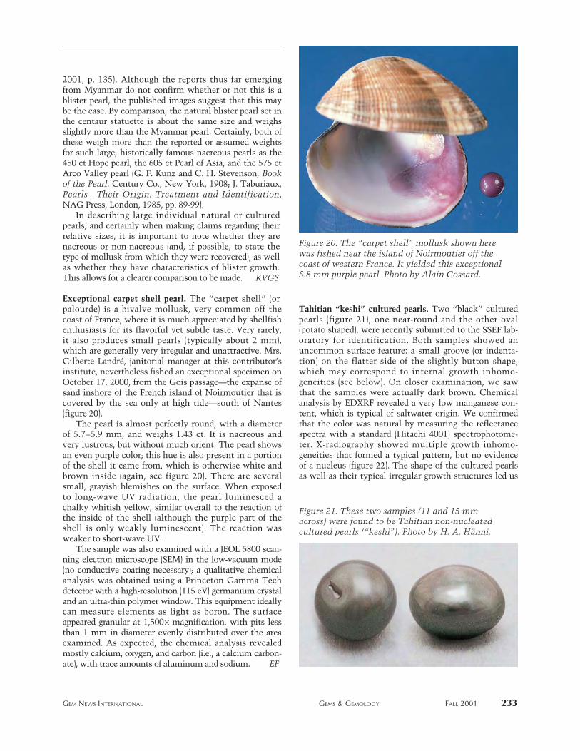
2001, p. 135). Although the reports thus far emergingfrom Myanmar do not confirm whether or not this is ablister pearl, the published images suggest that this maybe the case. By comparison, the natural blister pearl set inthe centaur statuette is about the same size and weighsslightly more than the Myanmar pearl. Certainly, both ofthese weigh more than the reported or assumed weightsfor such large, historically famous nacreous pearls as the450 ct Hope pearl, the 605 ct Pearl of Asia, and the 575 ctArco Valley pearl (G. F. Kunz and C. H. Stevenson, Bookof the Pearl, Century Co., New York, 1908; J. Taburiaux,Pearls—Their Origin, Treatment and Identification,NAG Press, London, 1985, pp. 89-99).
In describing large individual natural or culturedpearls, and certainly when making claims regarding theirrelative sizes, it is important to note whether they arenacreous or non-nacreous (and, if possible, to state thetype of mollusk from which they were recovered), as wellas whether they have characteristics of blister growth.This allows for a clearer comparison to be made. KVGS
Exceptional carpet shell pearl. The “carpet shell” (orpalourde) is a bivalve mollusk, very common off thecoast of France, where it is much appreciated by shellfishenthusiasts for its flavorful yet subtle taste. Very rarely,it also produces small pearls (typically about 2 mm),which are generally very irregular and unattractive. Mrs.Gilberte Landré, janitorial manager at this contributor’sinstitute, nevertheless fished an exceptional specimen onOctober 17, 2000, from the Gois passage—the expanse ofsand inshore of the French island of Noirmoutier that iscovered by the sea only at high tide—south of Nantes(figure 20).
The pearl is almost perfectly round, with a diameterof 5.7–5.9 mm, and weighs 1.43 ct. It is nacreous andvery lustrous, but without much orient. The pearl showsan even purple color; this hue is also present in a portionof the shell it came from, which is otherwise white andbrown inside (again, see figure 20). There are severalsmall, grayish blemishes on the surface. When exposedto long-wave UV radiation, the pearl luminesced achalky whitish yellow, similar overall to the reaction ofthe inside of the shell (although the purple part of theshell is only weakly luminescent). The reaction wasweaker to short-wave UV.
The sample was also examined with a JEOL 5800 scan-ning electron microscope (SEM) in the low-vacuum mode(no conductive coating necessary); a qualitative chemicalanalysis was obtained using a Princeton Gamma Techdetector with a high-resolution (115 eV) germanium crystaland an ultra-thin polymer window. This equipment ideallycan measure elements as light as boron. The surfaceappeared granular at 1,500¥ magnification, with pits lessthan 1 mm in diameter evenly distributed over the areaexamined. As expected, the chemical analysis revealedmostly calcium, oxygen, and carbon (i.e., a calcium carbon-ate), with trace amounts of aluminum and sodium. EF
Tahitian “keshi” cultured pearls. Two “black” culturedpearls (figure 21), one near-round and the other oval(potato shaped), were recently submitted to the SSEF lab-oratory for identification. Both samples showed anuncommon surface feature: a small groove (or indenta-tion) on the flatter side of the slightly button shape,which may correspond to internal growth inhomo-geneities (see below). On closer examination, we sawthat the samples were actually dark brown. Chemicalanalysis by EDXRF revealed a very low manganese con-tent, which is typical of saltwater origin. We confirmedthat the color was natural by measuring the reflectancespectra with a standard (Hitachi 4001) spectrophotome-ter. X-radiography showed multiple growth inhomo-geneities that formed a typical pattern, but no evidenceof a nucleus (figure 22). The shape of the cultured pearlsas well as their typical irregular growth structures led us
GEM NEWS INTERNATIONAL GEMS & GEMOLOGY FALL 2001 233
Figure 20. The “carpet shell” mollusk shown herewas fished near the island of Noirmoutier off thecoast of western France. It yielded this exceptional5.8 mm purple pearl. Photo by Alain Cossard.
Figure 21. These two samples (11 and 15 mmacross) were found to be Tahitian non-nucleatedcultured pearls (“keshi”). Photo by H. A. Hänni.
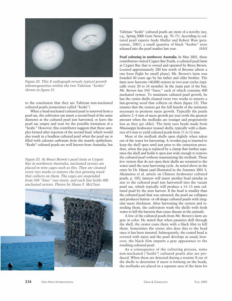
to the conclusion that they are Tahitian non-nucleatedcultured pearls (sometimes called “keshi”).
When a bead-nucleated cultured pearl is removed from apearl sac, the cultivator can insert a second bead of the samediameter as the cultured pearl just harvested, or leave thepearl sac empty and wait for the possible formation of a“keshi.” However, this contributor suggests that these sam-ples formed after rejection of the second bead, which wouldalso result in a beadless cultured pearl when the pearl sac isfilled with calcium carbonate from the mantle epithelium.“Keshi” cultured pearls are well known from Australia, but
Tahitian “keshi” cultured pearls are more of a novelty (see,e.g., Spring 2000 Gem News, pp. 70–71). According to cul-tured pearl experts Andy Muller and Robert Wan (pers.comm., 2001), a small quantity of black “keshis” werereleased into the pearl market last year. HAH
Pearl culturing in northwest Australia. In May 2001, thesecontributors visited Cygnet Bay Pearls, a cultured pearl farmat Cygnet Bay that is owned and operated by Bruce Brown.Located approximately 200 km north of Broome (about aone hour flight by small plane), Mr. Brown’s farm wasfounded 40 years ago by his father and older brother. Thefarm now harvests 140,000 oysters in two-year cycles (typi-cally every 20 to 24 months). In the main part of the bay,Mr. Brown has 350 “lines,” each of which contains 400nucleated oysters. To maximize cultured pearl growth, hehas the oyster shells cleaned every two weeks to remove afast-growing weed that collects on them (figure 23). Thisensures that the oysters get the full benefit of the nutrientsnecessary to promote nacre growth. Typically the pearlsachieve 2–4 mm of nacre growth per year (with the greatestamount when the mollusks are younger and progressivelyless as they get older). The farm uses beads made fromMississippi freshwater mussel shells, typically with a diam-eter of 6 mm to yield cultured pearls from 11 to 12 mm.
Most of the mollusk shells open slightly when takenout of the water for harvesting. A wooden peg is inserted tokeep the shell open until just prior to the extraction proce-dure, when the peg is replaced by a clamp that further sepa-rates the shell and holds it open just wide enough to removethe cultured pearl without traumatizing the mollusk. Thosefew oysters that do not open their shells are returned to thewater until the next harvesting cycle. As noted above in theentry by Dr. Hänni (and illustrated in the Summer 2001 S.Akamatsu et al. article on Chinese freshwater culturedpearls, p. 105), farmers will insert another bead (similar insize to the cultured pearl just harvested) into the vacantpearl sac, which typically will produce a 14–15 mm cul-tured pearl by the next harvest. If the bead is smaller thanthe cultured pearl that was extracted, the pearl sac collapsesand produces button- or off-shape cultured pearls with irreg-ular nacre thickness. After harvesting the oysters and re-seeding them, the cultivators wash the shells with freshwater to kill the bacteria that cause disease in the animals.
A few of the cultured pearls from Mr. Brown’s farm aregray in color. He stated that when parasites drill throughthe shell, the oyster coats them with a black film to killthem. Sometimes the oyster also does this to the beadonce it has been inserted. Subsequently, the coated bead iscovered with nacre and the pearl develops as usual; how-ever, the black film imparts a gray appearance to theresulting cultured pearl.
As a consequence of the culturing process, somenon-nucleated (“keshi”) cultured pearls also are pro-duced. When these are detected during a routine X-ray ofthe shells to determine if nacre is forming on the beads,the mollusks are placed in a separate area of the farm for
234 GEM NEWS INTERNATIONAL GEMS & GEMOLOGY FALL 2001
Figure 22. This X-radiograph reveals typical growthinhomogeneities within the two Tahitian “keshis”shown in figure 21.
Figure 23. At Bruce Brown’s pearl farm at CygnetBay in northwest Australia, nucleated oysters areplaced in wire cages such as this. They are cleanedevery two weeks to remove the fast-growing weedthat collects on them. The cages are suspendedfrom 350 “lines” (see inset), and each line holds 400nucleated oysters. Photos by Shane F. McClure.
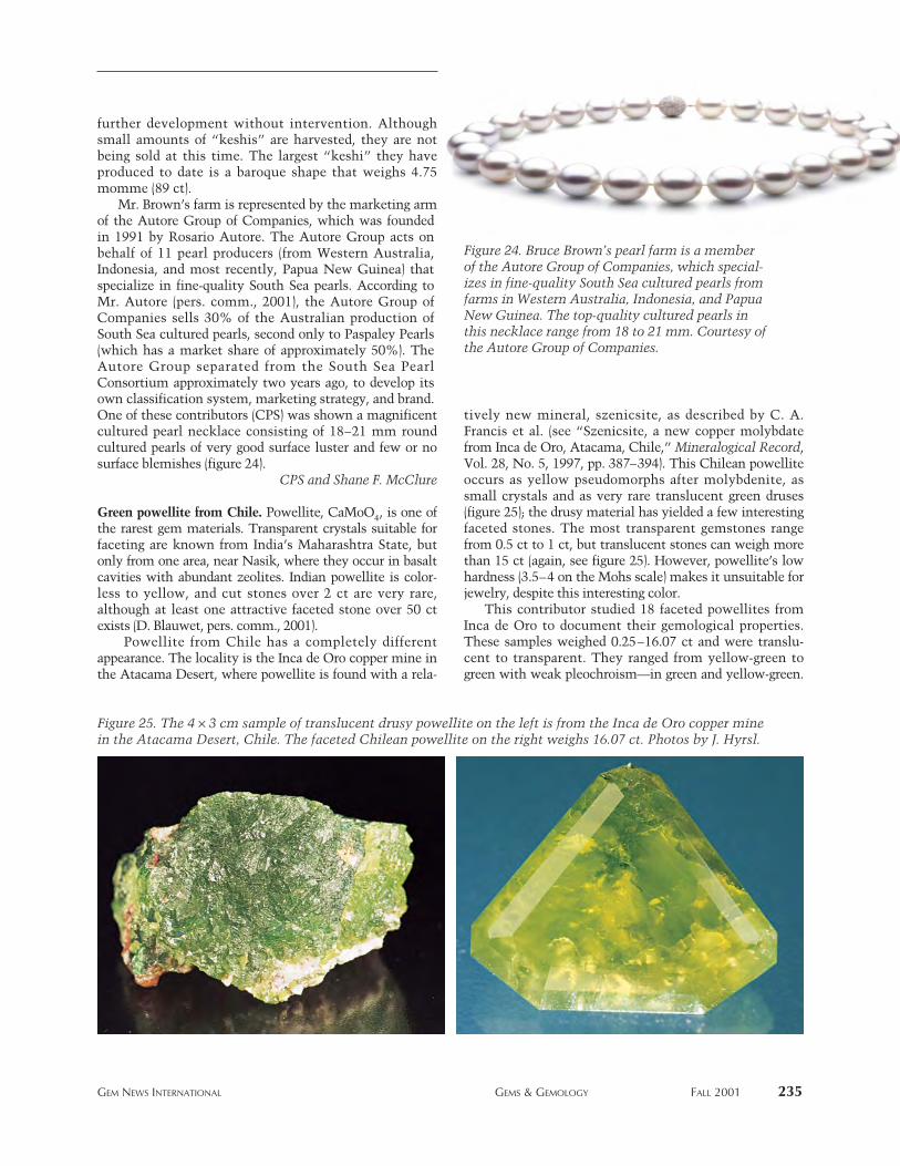
further development without intervention. Althoughsmall amounts of “keshis” are harvested, they are notbeing sold at this time. The largest “keshi” they haveproduced to date is a baroque shape that weighs 4.75momme (89 ct).
Mr. Brown’s farm is represented by the marketing armof the Autore Group of Companies, which was foundedin 1991 by Rosario Autore. The Autore Group acts onbehalf of 11 pearl producers (from Western Australia,Indonesia, and most recently, Papua New Guinea) thatspecialize in fine-quality South Sea pearls. According toMr. Autore (pers. comm., 2001), the Autore Group ofCompanies sells 30% of the Australian production ofSouth Sea cultured pearls, second only to Paspaley Pearls(which has a market share of approximately 50%). TheAutore Group separated from the South Sea PearlConsortium approximately two years ago, to develop itsown classification system, marketing strategy, and brand.One of these contributors (CPS) was shown a magnificentcultured pearl necklace consisting of 18–21 mm roundcultured pearls of very good surface luster and few or nosurface blemishes (figure 24).
CPS and Shane F. McClure
Green powellite from Chile. Powellite, CaMoO4, is one ofthe rarest gem materials. Transparent crystals suitable forfaceting are known from India’s Maharashtra State, butonly from one area, near Nasik, where they occur in basaltcavities with abundant zeolites. Indian powellite is color-less to yellow, and cut stones over 2 ct are very rare,although at least one attractive faceted stone over 50 ctexists (D. Blauwet, pers. comm., 2001).
Powellite from Chile has a completely differentappearance. The locality is the Inca de Oro copper mine inthe Atacama Desert, where powellite is found with a rela-
tively new mineral, szenicsite, as described by C. A.Francis et al. (see “Szenicsite, a new copper molybdatefrom Inca de Oro, Atacama, Chile,” Mineralogical Record,Vol. 28, No. 5, 1997, pp. 387–394). This Chilean powelliteoccurs as yellow pseudomorphs after molybdenite, assmall crystals and as very rare translucent green druses(figure 25); the drusy material has yielded a few interestingfaceted stones. The most transparent gemstones rangefrom 0.5 ct to 1 ct, but translucent stones can weigh morethan 15 ct (again, see figure 25). However, powellite’s lowhardness (3.5–4 on the Mohs scale) makes it unsuitable forjewelry, despite this interesting color.
This contributor studied 18 faceted powellites fromInca de Oro to document their gemological properties.These samples weighed 0.25–16.07 ct and were translu-cent to transparent. They ranged from yellow-green togreen with weak pleochroism—in green and yellow-green.
GEM NEWS INTERNATIONAL GEMS & GEMOLOGY FALL 2001 235
Figure 24. Bruce Brown’s pearl farm is a memberof the Autore Group of Companies, which special-izes in fine-quality South Sea cultured pearls fromfarms in Western Australia, Indonesia, and PapuaNew Guinea. The top-quality cultured pearls inthis necklace range from 18 to 21 mm. Courtesy ofthe Autore Group of Companies.
Figure 25. The 4 ¥ 3 cm sample of translucent drusy powellite on the left is from the Inca de Oro copper minein the Atacama Desert, Chile. The faceted Chilean powellite on the right weighs 16.07 ct. Photos by J. Hyrsl.
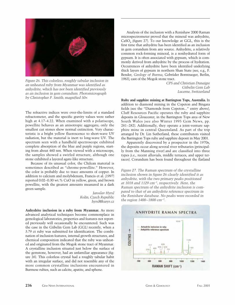
The refractive indices were over-the-limits of a standardrefractometer, and the specific gravity values were ratherhigh at 4.17–4.22. When examined with a polariscope,powellite behaves as an anisotropic aggregate; only thesmallest cut stones show normal extinction. Very charac-teristic is a bright yellow fluorescence to short-wave UVradiation, but the material is inert to long-wave UV. Thespectrum seen with a handheld spectroscope exhibitedcomplete absorption of the blue and purple regions, start-ing from about 460 nm. When viewed with a microscope,the samples showed a swirled structure, although onestone exhibited a layered agate-like structure.
Because of its unusual color, the Chilean material issometimes described as “chrome-powellite.” However,the color is probably due to trace amounts of copper. Inaddition to calcium and molybdenum, Francis et al. (1997)reported 0.02–0.30 wt.% CuO in yellow, green, and brownpowellite, with the greatest amounts measured in a darkgreen sample.
Jaroslav HyrslKolin, Czech Republic
Anhydrite inclusion in a ruby from Myanmar. As moreadvanced analytical techniques become commonplace ingemological laboratories, properties and features not report-ed previously will occasionally be encountered. Such wasthe case in the Gübelin Gem Lab (GGL) recently, when a3.79 ct ruby was submitted for identification. The combi-nation of inclusion features, internal growth structures, andchemical composition indicated that the ruby was unheat-ed and originated from the Mogok stone tract of Myanmar.A crystalline inclusion situated just below the surface ofthe gemstone, however, had an unfamiliar appearance (fig-ure 26). This colorless crystal had a roughly tabular habitwith an irregular surface, and did not resemble any of themore common crystalline inclusions encountered inBurmese rubies, such as calcite, apatite, and sphene.
Analysis of the inclusion with a Renishaw 2000 Ramanmicrospectrometer proved that the mineral was anhydrite,CaSO4 (figure 27). To our knowledge at GGL, this is thefirst time that anhydrite has been identified as an inclusionin gem corundum from any source. Anhydrite, a relativelycommon rock-forming mineral, is a nonhydrated form ofgypsum. It is often associated with gypsum, which is com-monly derived from anhydrite by the process of hydration.Occurrences of anhydrite have been identified underlyingthick layers of gypsum in northern Shan State (see, e.g., F.Bender, Geology of Burma, Gebrüder Borntraeger, Berlin,1983), east of the Mogok stone tract.
CPS and Christian DunaigreGübelin Gem Lab
Lucerne, Switzerland
Ruby and sapphire mining at Barrington Tops, Australia. Inaddition to diamond mining in the Copeton and Bingarafields (see the “Diamonds from Copeton...” entry above),Cluff Resources Pacific operates the ruby and sapphiredeposits in Gloucester, in the Barrington Tops area of NewSouth Wales (see also Winter 1995 Gem News, pp.281–282). Additionally, they operate a joint-venture sap-phire mine in central Queensland. As part of the triparranged by Dr. Lin Sutherland, these contributors visitedthe Barrington Tops ruby and sapphire deposit in May 2001.
Apparently discovered by a prospector in the 1970s,the deposits occur along several river tributaries (principal-ly from the Manning river) and are classified into threetypes (i.e., recent alluvials, middle terraces, and upper ter-races). Corundum has been found throughout the flatland
236 GEM NEWS INTERNATIONAL GEMS & GEMOLOGY FALL 2001
Figure 26. This colorless, roughly tabular inclusion inan unheated ruby from Myanmar was identified asanhydrite, which has not been identified previouslyas an inclusion in gem corundum. Photomicrographby Christopher P. Smith; magnified 50¥
Figure 27. The Raman spectrum of the crystallineinclusion shown in figure 26 clearly identified it asanhydrite, with the two primary peaks positionedat 1018 and 1129 cm-1, respectively. Here, theRaman spectrum of the anhydrite inclusion is com-pared to that of an anhydrite reference spectrum inthe Renishaw database. No peaks were recorded inthe region 1400–1800 cm-1.
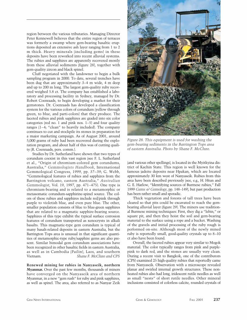
region between the various tributaries. Managing DirectorPeter Kennewell believes that the entire region of terraceswas formerly a swamp where gem-bearing basaltic erup-tions deposited an extensive ash layer ranging from 1 to 2m thick. Heavy minerals (including gems) in thesedeposits have been reworked into recent alluvial systems.The rubies and sapphires are apparently recovered mostlyfrom these alluvial sediments (figure 28), together withgem-quality zircon and black spinel.
Cluff negotiated with the landowner to begin a bulksampling program in 2000. To date, several trenches havebeen dug that are approximately 3–4 m wide, 4 m deepand up to 200 m long. The largest gem-quality ruby recov-ered weighed 5.8 ct. The company has established a labo-ratory and processing facility in Sydney, managed by Dr.Robert Coenraads, to begin developing a market for theirgemstones. Dr. Coenraads has developed a classificationsystem for the various colors of corundum (yellow throughgreen, to blue, and parti-colors) that they produce. Thefaceted rubies and pink sapphires are graded into six colorcategories (red no. 1 and pink nos. 1–5) and four qualityranges (1–4; “clean” to heavily included). The companycontinues to cut and stockpile its stones in preparation fora major marketing campaign. As of August 2001, around5,000 grams of ruby had been recovered during the explo-ration program, and about half of this was of cutting quali-ty (R. Coenraads, pers. comm.).
Studies by Dr. Sutherland have shown that two types ofcorundum coexist in this vast region (see F. L. Sutherlandet al., “Origin of chromium-colored gem corundums,Australia,” Gemmologists Handbook, InternationalGemmological Congress, 1999, pp. 37–39; G. Webb,“Gemmological features of rubies and sapphires from theBarrington volcano, eastern Australia,” AustralianGemmologist, Vol. 19, 1997, pp. 471–475). One type ischromium-bearing and is related to a metamorphic ormetasomatic corundum-sapphirine-spinel source. The col-ors of these rubies and sapphires include red/pink throughpurple to violetish blue, and even pure blue. The other,smaller population consists of blue to blue-green sapphiresthat are related to a magmatic sapphire-bearing source.Sapphires of this type exhibit the typical surface corrosionfeatures of corundum transported as xenocrysts in alkalibasalts. This magmatic-type gem corundum is typical ofmany basalt-related deposits in eastern Australia, but theBarrington Tops area is unusual in that significant quanti-ties of metamorphic-type ruby/sapphire gems are also pre-sent. Similar bimodal gem corundum associations havebeen recognized in other basaltic fields in eastern Australia,as well as in Cambodia (Pailin), Laos, and southernVietnam. Shane F. McClure and CPS
Renewed mining for rubies in Nanyaseik, northernMyanmar. Over the past few months, thousands of minershave converged on the Nanyaseik area of northernMyanmar, in a new “gem rush” for ruby and pink sapphires,as well as spinel. The area, also referred to as Nanyar Zeik
(and various other spellings), is located in the Myitkyina dis-trict of Kachin State. This region is well known for thefamous jadeite deposits near Hpakan, which are locatedapproximately 30 km west of Nanyaseik. Rubies from thisarea have been described previously (see, e.g., H. Htun andG. E. Harlow, “Identifying sources of Burmese rubies,” Fall1999 Gems & Gemology, pp. 148–149), but past productionhas been rather small and sporadic.
Thick vegetation and forests of tall trees have beencleared so that pits could be excavated to reach the gem-bearing alluvial layer (figure 29). The miners use tradition-al Burmese mining techniques: First, they dig a “lebin,” orsquare pit, and then they hoist the soil and gem-bearingmaterial to the surface using a rope and a bucket. Washingof the gravels and initial processing of the ruby rough isperformed on-site. Although most of the newly minedruby is reportedly small, good-quality crystals up to 8–10ct also have been found.
Overall, the faceted rubies appear very similar to Mogokmaterial. The color typically ranges from pink and purple-pink to dark red, and the stones are usually very clean.During a recent visit to Bangkok, one of the contributors(CPS) examined 25 high-quality rubies that reportedly camefrom Nanyaseik. Observation with a microscope revealedplanar and swirled internal growth structures. These non-heated rubies also had long, iridescent rutile needles as wellas small “nests” of short rutile needles. Other mineralinclusions consisted of colorless calcite, rounded crystals of
GEM NEWS INTERNATIONAL GEMS & GEMOLOGY FALL 2001 237
Figure 28. This equipment is used for washing thegem-bearing sediments in the Barrington Tops areaof eastern Australia. Photo by Shane F. McClure.
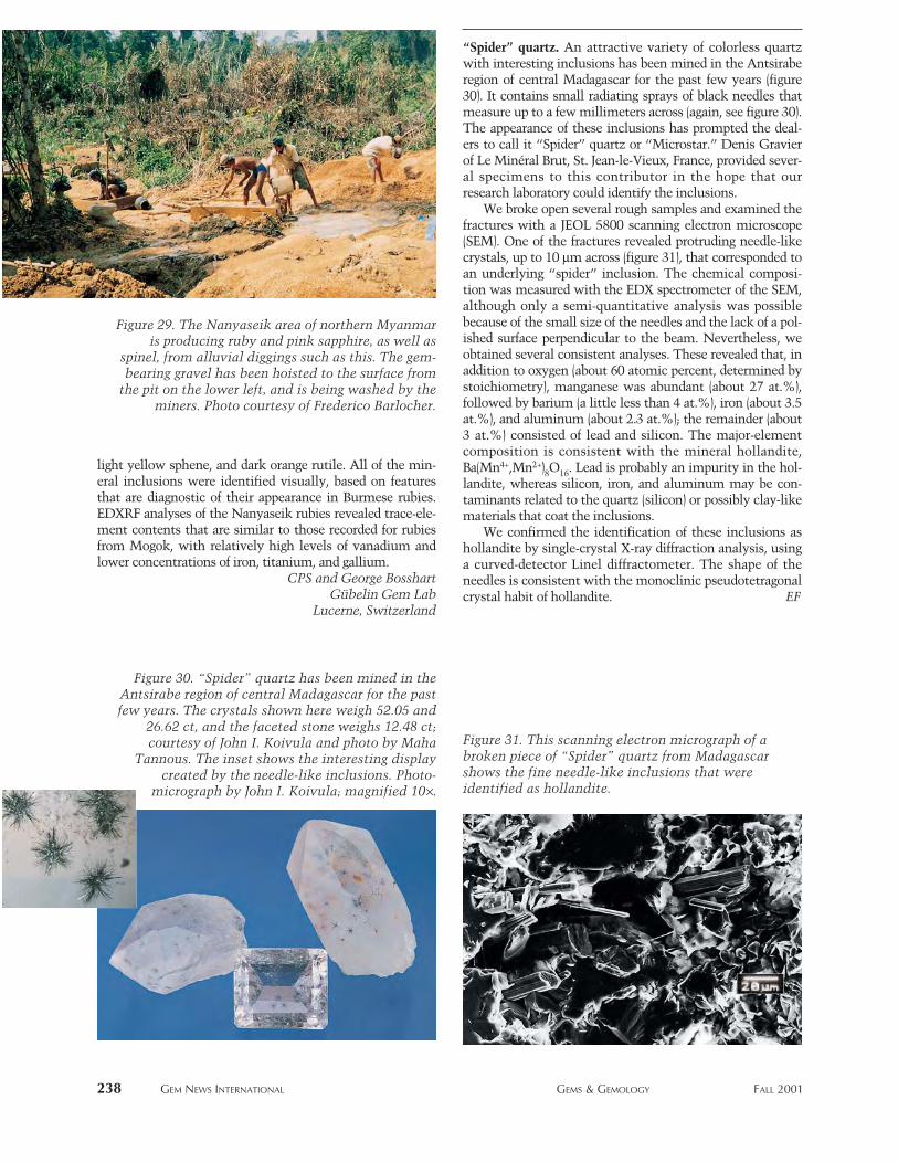
light yellow sphene, and dark orange rutile. All of the min-eral inclusions were identified visually, based on featuresthat are diagnostic of their appearance in Burmese rubies.EDXRF analyses of the Nanyaseik rubies revealed trace-ele-ment contents that are similar to those recorded for rubiesfrom Mogok, with relatively high levels of vanadium andlower concentrations of iron, titanium, and gallium.
CPS and George BosshartGübelin Gem Lab
Lucerne, Switzerland
“Spider” quartz. An attractive variety of colorless quartzwith interesting inclusions has been mined in the Antsiraberegion of central Madagascar for the past few years (figure30). It contains small radiating sprays of black needles thatmeasure up to a few millimeters across (again, see figure 30).The appearance of these inclusions has prompted the deal-ers to call it “Spider” quartz or “Microstar.” Denis Gravierof Le Minéral Brut, St. Jean-le-Vieux, France, provided sever-al specimens to this contributor in the hope that ourresearch laboratory could identify the inclusions.
We broke open several rough samples and examined thefractures with a JEOL 5800 scanning electron microscope(SEM). One of the fractures revealed protruding needle-likecrystals, up to 10 mm across (figure 31), that corresponded toan underlying “spider” inclusion. The chemical composi-tion was measured with the EDX spectrometer of the SEM,although only a semi-quantitative analysis was possiblebecause of the small size of the needles and the lack of a pol-ished surface perpendicular to the beam. Nevertheless, weobtained several consistent analyses. These revealed that, inaddition to oxygen (about 60 atomic percent, determined bystoichiometry), manganese was abundant (about 27 at.%),followed by barium (a little less than 4 at.%), iron (about 3.5at.%), and aluminum (about 2.3 at.%); the remainder (about3 at.%) consisted of lead and silicon. The major-elementcomposition is consistent with the mineral hollandite,Ba(Mn4+,Mn2+)8O16. Lead is probably an impurity in the hol-landite, whereas silicon, iron, and aluminum may be con-taminants related to the quartz (silicon) or possibly clay-likematerials that coat the inclusions.
We confirmed the identification of these inclusions ashollandite by single-crystal X-ray diffraction analysis, usinga curved-detector Linel diffractometer. The shape of theneedles is consistent with the monoclinic pseudotetragonalcrystal habit of hollandite. EF
238 GEM NEWS INTERNATIONAL GEMS & GEMOLOGY FALL 2001
Figure 29. The Nanyaseik area of northern Myanmaris producing ruby and pink sapphire, as well as
spinel, from alluvial diggings such as this. The gem-bearing gravel has been hoisted to the surface from
the pit on the lower left, and is being washed by theminers. Photo courtesy of Frederico Barlocher.
Figure 30. “Spider” quartz has been mined in theAntsirabe region of central Madagascar for the pastfew years. The crystals shown here weigh 52.05 and
26.62 ct, and the faceted stone weighs 12.48 ct;courtesy of John I. Koivula and photo by Maha
Tannous. The inset shows the interesting displaycreated by the needle-like inclusions. Photo-
micrograph by John I. Koivula; magnified 10¥.
Figure 31. This scanning electron micrograph of abroken piece of “Spider” quartz from Madagascarshows the fine needle-like inclusions that wereidentified as hollandite.
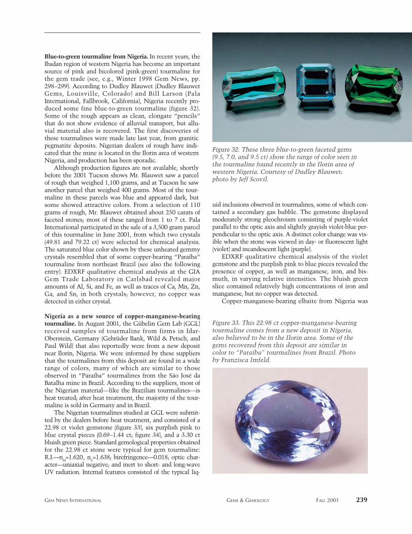
Blue-to-green tourmaline from Nigeria. In recent years, theIbadan region of western Nigeria has become an importantsource of pink and bicolored (pink-green) tourmaline forthe gem trade (see, e.g., Winter 1998 Gem News, pp.298–299). According to Dudley Blauwet (Dudley BlauwetGems, Louisville, Colorado) and Bill Larson (PalaInternational, Fallbrook, California), Nigeria recently pro-duced some fine blue-to-green tourmaline (figure 32).Some of the rough appears as clean, elongate “pencils”that do not show evidence of alluvial transport, but allu-vial material also is recovered. The first discoveries ofthese tourmalines were made late last year, from graniticpegmatite deposits. Nigerian dealers of rough have indi-cated that the mine is located in the Ilorin area of westernNigeria, and production has been sporadic.
Although production figures are not available, shortlybefore the 2001 Tucson shows Mr. Blauwet saw a parcelof rough that weighed 1,100 grams, and at Tucson he sawanother parcel that weighed 400 grams. Most of the tour-maline in these parcels was blue and appeared dark, butsome showed attractive colors. From a selection of 110grams of rough, Mr. Blauwet obtained about 250 carats offaceted stones; most of these ranged from 1 to 7 ct. PalaInternational participated in the sale of a 3,500 gram parcelof this tourmaline in June 2001, from which two crystals(49.81 and 79.22 ct) were selected for chemical analysis.The saturated blue color shown by these unheated gemmycrystals resembled that of some copper-bearing “Paraíba”tourmaline from northeast Brazil (see also the followingentry). EDXRF qualitative chemical analysis at the GIAGem Trade Laboratory in Carlsbad revealed majoramounts of Al, Si, and Fe, as well as traces of Ca, Mn, Zn,Ga, and Sn, in both crystals; however, no copper wasdetected in either crystal.
Nigeria as a new source of copper-manganese-bearingtourmaline. In August 2001, the Gübelin Gem Lab (GGL)received samples of tourmaline from firms in Idar-Oberstein, Germany (Gebrüder Bank, Wild & Petsch, andPaul Wild) that also reportedly were from a new depositnear Ilorin, Nigeria. We were informed by these suppliersthat the tourmalines from this deposit are found in a widerange of colors, many of which are similar to thoseobserved in “Paraíba” tourmalines from the São José daBatalha mine in Brazil. According to the suppliers, most ofthe Nigerian material—like the Brazilian tourmalines—isheat treated; after heat treatment, the majority of the tour-maline is sold in Germany and in Brazil.
The Nigerian tourmalines studied at GGL were submit-ted by the dealers before heat treatment, and consisted of a22.98 ct violet gemstone (figure 33), six purplish pink toblue crystal pieces (0.69–1.44 ct; figure 34), and a 3.30 ctbluish green piece. Standard gemological properties obtainedfor the 22.98 ct stone were typical for gem tourmaline:R.I.—nw=1.620, ne=1.638; birefringence—0.018; optic char-acter—uniaxial negative; and inert to short- and long-waveUV radiation. Internal features consisted of the typical liq-
uid inclusions observed in tourmalines, some of which con-tained a secondary gas bubble. The gemstone displayedmoderately strong pleochroism consisting of purple-violetparallel to the optic axis and slightly grayish violet-blue per-pendicular to the optic axis. A distinct color change was vis-ible when the stone was viewed in day- or fluorescent light(violet) and incandescent light (purple).
EDXRF qualitative chemical analysis of the violetgemstone and the purplish pink to blue pieces revealed thepresence of copper, as well as manganese, iron, and bis-muth, in varying relative intensities. The bluish greenslice contained relatively high concentrations of iron andmanganese, but no copper was detected.
Copper-manganese-bearing elbaite from Nigeria was
GEM NEWS INTERNATIONAL GEMS & GEMOLOGY FALL 2001 239
Figure 32. These three blue-to-green faceted gems(9.5, 7.0, and 9.5 ct) show the range of color seen inthe tourmaline found recently in the Ilorin area ofwestern Nigeria. Courtesy of Dudley Blauwet;photo by Jeff Scovil.
Figure 33. This 22.98 ct copper-manganese-bearingtourmaline comes from a new deposit in Nigeria,also believed to be in the Ilorin area. Some of thegems recovered from this deposit are similar incolor to “Paraíba” tourmalines from Brazil. Photoby Franzisca Imfeld.
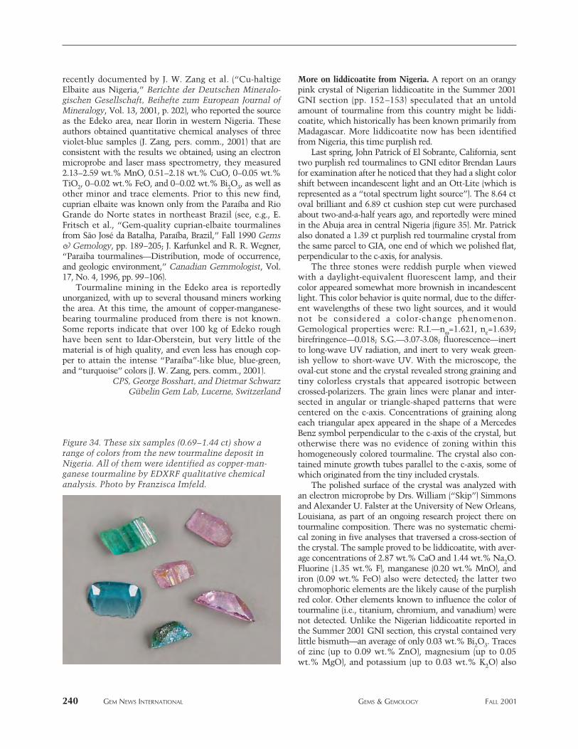
recently documented by J. W. Zang et al. (“Cu-haltigeElbaite aus Nigeria,” Berichte der Deutschen Mineralo-gischen Gesellschaft, Beihefte zum European Journal ofMineralogy, Vol. 13, 2001, p. 202), who reported the sourceas the Edeko area, near Ilorin in western Nigeria. Theseauthors obtained quantitative chemical analyses of threeviolet-blue samples (J. Zang, pers. comm., 2001) that areconsistent with the results we obtained; using an electronmicroprobe and laser mass spectrometry, they measured2.13–2.59 wt.% MnO, 0.51–2.18 wt.% CuO, 0–0.05 wt.%TiO2, 0–0.02 wt.% FeO, and 0–0.02 wt.% Bi2O3, as well asother minor and trace elements. Prior to this new find,cuprian elbaite was known only from the Paraíba and RioGrande do Norte states in northeast Brazil (see, e.g., E.Fritsch et al., “Gem-quality cuprian-elbaite tourmalinesfrom São José da Batalha, Paraíba, Brazil,” Fall 1990 Gems& Gemology, pp. 189–205; J. Karfunkel and R. R. Wegner,“Paraiba tourmalines—Distribution, mode of occurrence,and geologic environment,” Canadian Gemmologist, Vol.17, No. 4, 1996, pp. 99–106).
Tourmaline mining in the Edeko area is reportedlyunorganized, with up to several thousand miners workingthe area. At this time, the amount of copper-manganese-bearing tourmaline produced from there is not known.Some reports indicate that over 100 kg of Edeko roughhave been sent to Idar-Oberstein, but very little of thematerial is of high quality, and even less has enough cop-per to attain the intense “Paraíba”-like blue, blue-green,and “turquoise” colors (J. W. Zang, pers. comm., 2001).
CPS, George Bosshart, and Dietmar SchwarzGübelin Gem Lab, Lucerne, Switzerland
More on liddicoatite from Nigeria. A report on an orangypink crystal of Nigerian liddicoatite in the Summer 2001GNI section (pp. 152–153) speculated that an untoldamount of tourmaline from this country might be liddi-coatite, which historically has been known primarily fromMadagascar. More liddicoatite now has been identifiedfrom Nigeria, this time purplish red.
Last spring, John Patrick of El Sobrante, California, senttwo purplish red tourmalines to GNI editor Brendan Laursfor examination after he noticed that they had a slight colorshift between incandescent light and an Ott-Lite (which isrepresented as a “total spectrum light source”). The 8.64 ctoval brilliant and 6.89 ct cushion step cut were purchasedabout two-and-a-half years ago, and reportedly were minedin the Abuja area in central Nigeria (figure 35). Mr. Patrickalso donated a 1.39 ct purplish red tourmaline crystal fromthe same parcel to GIA, one end of which we polished flat,perpendicular to the c-axis, for analysis.
The three stones were reddish purple when viewedwith a daylight-equivalent fluorescent lamp, and theircolor appeared somewhat more brownish in incandescentlight. This color behavior is quite normal, due to the differ-ent wavelengths of these two light sources, and it wouldnot be considered a color-change phenomenon.Gemological properties were: R.I.—nw=1.621, ne=1.639;birefringence—0.018; S.G.—3.07-3.08; fluorescence—inertto long-wave UV radiation, and inert to very weak green-ish yellow to short-wave UV. With the microscope, theoval-cut stone and the crystal revealed strong graining andtiny colorless crystals that appeared isotropic betweencrossed-polarizers. The grain lines were planar and inter-sected in angular or triangle-shaped patterns that werecentered on the c-axis. Concentrations of graining alongeach triangular apex appeared in the shape of a MercedesBenz symbol perpendicular to the c-axis of the crystal, butotherwise there was no evidence of zoning within thishomogeneously colored tourmaline. The crystal also con-tained minute growth tubes parallel to the c-axis, some ofwhich originated from the tiny included crystals.
The polished surface of the crystal was analyzed withan electron microprobe by Drs. William (“Skip”) Simmonsand Alexander U. Falster at the University of New Orleans,Louisiana, as part of an ongoing research project there ontourmaline composition. There was no systematic chemi-cal zoning in five analyses that traversed a cross-section ofthe crystal. The sample proved to be liddicoatite, with aver-age concentrations of 2.87 wt.% CaO and 1.44 wt.% Na2O.Fluorine (1.35 wt.% F), manganese (0.20 wt.% MnO), andiron (0.09 wt.% FeO) also were detected; the latter twochromophoric elements are the likely cause of the purplishred color. Other elements known to influence the color oftourmaline (i.e., titanium, chromium, and vanadium) werenot detected. Unlike the Nigerian liddicoatite reported inthe Summer 2001 GNI section, this crystal contained verylittle bismuth—an average of only 0.03 wt.% Bi2O3. Tracesof zinc (up to 0.09 wt.% ZnO), magnesium (up to 0.05wt.% MgO), and potassium (up to 0.03 wt.% K2O) also
240 GEM NEWS INTERNATIONAL GEMS & GEMOLOGY FALL 2001
Figure 34. These six samples (0.69–1.44 ct) show arange of colors from the new tourmaline deposit inNigeria. All of them were identified as copper-man-ganese tourmaline by EDXRF qualitative chemicalanalysis. Photo by Franzisca Imfeld.
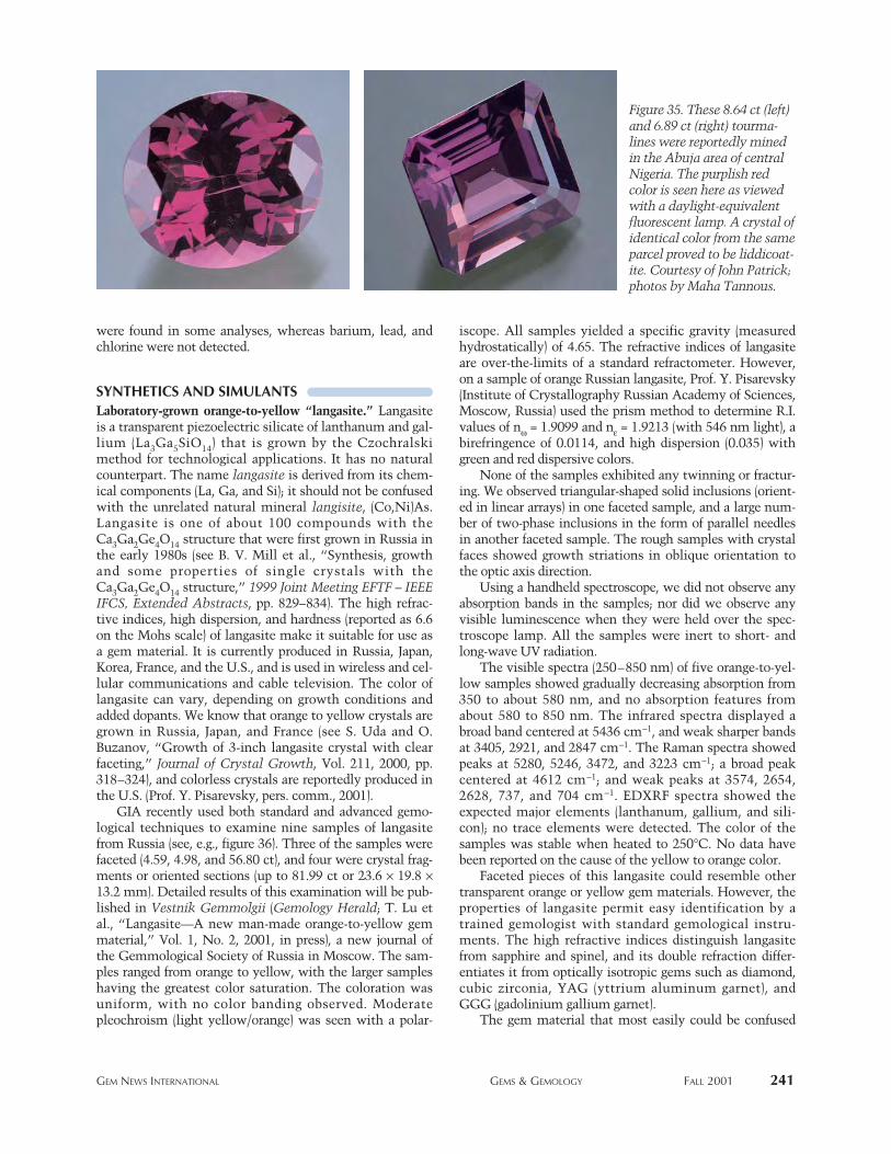
were found in some analyses, whereas barium, lead, andchlorine were not detected.
SYNTHETICS AND SIMULANTSLaboratory-grown orange-to-yellow “langasite.” Langasiteis a transparent piezoelectric silicate of lanthanum and gal-lium (La3Ga5SiO14) that is grown by the Czochralskimethod for technological applications. It has no naturalcounterpart. The name langasite is derived from its chem-ical components (La, Ga, and Si); it should not be confusedwith the unrelated natural mineral langisite, (Co,Ni)As.Langasite is one of about 100 compounds with theCa3Ga2Ge4O14 structure that were first grown in Russia inthe early 1980s (see B. V. Mill et al., “Synthesis, growthand some properties of single crystals with theCa3Ga2Ge4O14 structure,” 1999 Joint Meeting EFTF – IEEEIFCS, Extended Abstracts, pp. 829–834). The high refrac-tive indices, high dispersion, and hardness (reported as 6.6on the Mohs scale) of langasite make it suitable for use asa gem material. It is currently produced in Russia, Japan,Korea, France, and the U.S., and is used in wireless and cel-lular communications and cable television. The color oflangasite can vary, depending on growth conditions andadded dopants. We know that orange to yellow crystals aregrown in Russia, Japan, and France (see S. Uda and O.Buzanov, “Growth of 3-inch langasite crystal with clearfaceting,” Journal of Crystal Growth, Vol. 211, 2000, pp.318–324), and colorless crystals are reportedly produced inthe U.S. (Prof. Y. Pisarevsky, pers. comm., 2001).
GIA recently used both standard and advanced gemo-logical techniques to examine nine samples of langasitefrom Russia (see, e.g., figure 36). Three of the samples werefaceted (4.59, 4.98, and 56.80 ct), and four were crystal frag-ments or oriented sections (up to 81.99 ct or 23.6 ¥ 19.8 ¥13.2 mm). Detailed results of this examination will be pub-lished in Vestnik Gemmolgii (Gemology Herald; T. Lu etal., “Langasite—A new man-made orange-to-yellow gemmaterial,” Vol. 1, No. 2, 2001, in press), a new journal ofthe Gemmological Society of Russia in Moscow. The sam-ples ranged from orange to yellow, with the larger sampleshaving the greatest color saturation. The coloration wasuniform, with no color banding observed. Moderatepleochroism (light yellow/orange) was seen with a polar-
iscope. All samples yielded a specific gravity (measuredhydrostatically) of 4.65. The refractive indices of langasiteare over-the-limits of a standard refractometer. However,on a sample of orange Russian langasite, Prof. Y. Pisarevsky(Institute of Crystallography Russian Academy of Sciences,Moscow, Russia) used the prism method to determine R.I.values of nw = 1.9099 and ne = 1.9213 (with 546 nm light), abirefringence of 0.0114, and high dispersion (0.035) withgreen and red dispersive colors.
None of the samples exhibited any twinning or fractur-ing. We observed triangular-shaped solid inclusions (orient-ed in linear arrays) in one faceted sample, and a large num-ber of two-phase inclusions in the form of parallel needlesin another faceted sample. The rough samples with crystalfaces showed growth striations in oblique orientation tothe optic axis direction.
Using a handheld spectroscope, we did not observe anyabsorption bands in the samples; nor did we observe anyvisible luminescence when they were held over the spec-troscope lamp. All the samples were inert to short- andlong-wave UV radiation.
The visible spectra (250–850 nm) of five orange-to-yel-low samples showed gradually decreasing absorption from350 to about 580 nm, and no absorption features fromabout 580 to 850 nm. The infrared spectra displayed abroad band centered at 5436 cm-1, and weak sharper bandsat 3405, 2921, and 2847 cm-1. The Raman spectra showedpeaks at 5280, 5246, 3472, and 3223 cm-1; a broad peakcentered at 4612 cm-1; and weak peaks at 3574, 2654,2628, 737, and 704 cm-1. EDXRF spectra showed theexpected major elements (lanthanum, gallium, and sili-con); no trace elements were detected. The color of thesamples was stable when heated to 250°C. No data havebeen reported on the cause of the yellow to orange color.
Faceted pieces of this langasite could resemble othertransparent orange or yellow gem materials. However, theproperties of langasite permit easy identification by atrained gemologist with standard gemological instru-ments. The high refractive indices distinguish langasitefrom sapphire and spinel, and its double refraction differ-entiates it from optically isotropic gems such as diamond,cubic zirconia, YAG (yttrium aluminum garnet), andGGG (gadolinium gallium garnet).
The gem material that most easily could be confused
Figure 35. These 8.64 ct (left)and 6.89 ct (right) tourma-lines were reportedly minedin the Abuja area of centralNigeria. The purplish redcolor is seen here as viewedwith a daylight-equivalentfluorescent lamp. A crystal ofidentical color from the sameparcel proved to be liddicoat-ite. Courtesy of John Patrick;photos by Maha Tannous.
GEM NEWS INTERNATIONAL GEMS & GEMOLOGY FALL 2001 241
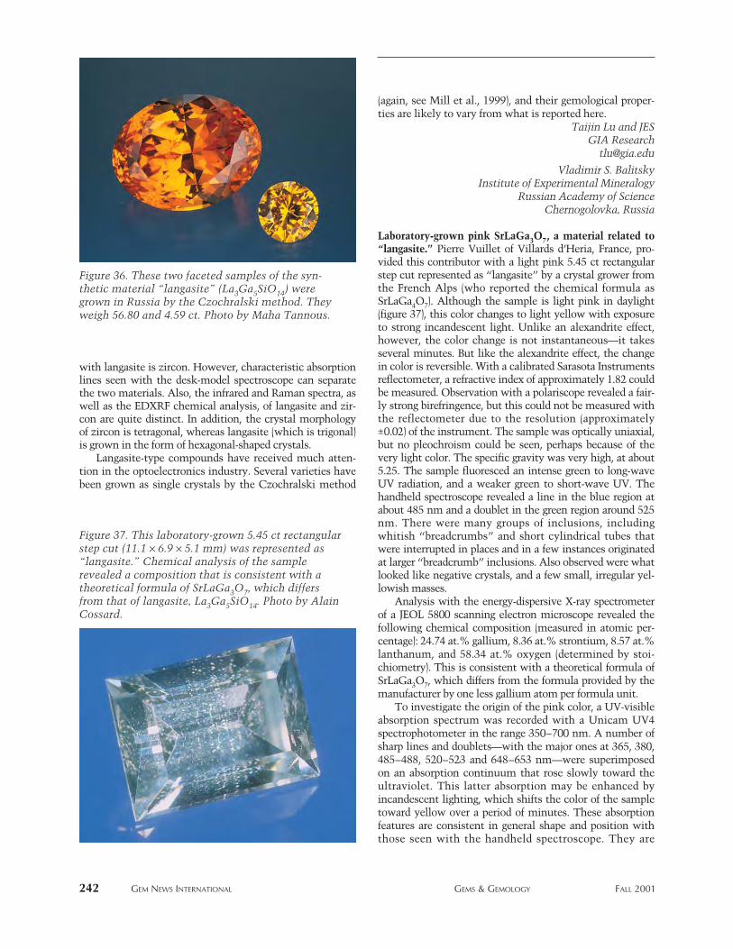
242 GEM NEWS INTERNATIONAL GEMS & GEMOLOGY FALL 2001
with langasite is zircon. However, characteristic absorptionlines seen with the desk-model spectroscope can separatethe two materials. Also, the infrared and Raman spectra, aswell as the EDXRF chemical analysis, of langasite and zir-con are quite distinct. In addition, the crystal morphologyof zircon is tetragonal, whereas langasite (which is trigonal)is grown in the form of hexagonal-shaped crystals.
Langasite-type compounds have received much atten-tion in the optoelectronics industry. Several varieties havebeen grown as single crystals by the Czochralski method
(again, see Mill et al., 1999), and their gemological proper-ties are likely to vary from what is reported here.
Taijin Lu and JESGIA Research
Vladimir S. BalitskyInstitute of Experimental Mineralogy
Russian Academy of ScienceChernogolovka, Russia
Laboratory-grown pink SrLaGa3O7, a material related to“langasite.” Pierre Vuillet of Villards d’Heria, France, pro-vided this contributor with a light pink 5.45 ct rectangularstep cut represented as “langasite” by a crystal grower fromthe French Alps (who reported the chemical formula asSrLaGa4O7). Although the sample is light pink in daylight(figure 37), this color changes to light yellow with exposureto strong incandescent light. Unlike an alexandrite effect,however, the color change is not instantaneous—it takesseveral minutes. But like the alexandrite effect, the changein color is reversible. With a calibrated Sarasota Instrumentsreflectometer, a refractive index of approximately 1.82 couldbe measured. Observation with a polariscope revealed a fair-ly strong birefringence, but this could not be measured withthe reflectometer due to the resolution (approximately±0.02) of the instrument. The sample was optically uniaxial,but no pleochroism could be seen, perhaps because of thevery light color. The specific gravity was very high, at about5.25. The sample fluoresced an intense green to long-waveUV radiation, and a weaker green to short-wave UV. Thehandheld spectroscope revealed a line in the blue region atabout 485 nm and a doublet in the green region around 525nm. There were many groups of inclusions, includingwhitish “breadcrumbs” and short cylindrical tubes thatwere interrupted in places and in a few instances originatedat larger “breadcrumb” inclusions. Also observed were whatlooked like negative crystals, and a few small, irregular yel-lowish masses.
Analysis with the energy-dispersive X-ray spectrometerof a JEOL 5800 scanning electron microscope revealed thefollowing chemical composition (measured in atomic per-centage): 24.74 at.% gallium, 8.36 at.% strontium, 8.57 at.%lanthanum, and 58.34 at.% oxygen (determined by stoi-chiometry). This is consistent with a theoretical formula ofSrLaGa3O7, which differs from the formula provided by themanufacturer by one less gallium atom per formula unit.
To investigate the origin of the pink color, a UV-visibleabsorption spectrum was recorded with a Unicam UV4spectrophotometer in the range 350–700 nm. A number ofsharp lines and doublets—with the major ones at 365, 380,485–488, 520–523 and 648–653 nm—were superimposedon an absorption continuum that rose slowly toward theultraviolet. This latter absorption may be enhanced byincandescent lighting, which shifts the color of the sampletoward yellow over a period of minutes. These absorptionfeatures are consistent in general shape and position withthose seen with the handheld spectroscope. They are
Figure 37. This laboratory-grown 5.45 ct rectangularstep cut (11.1 ¥ 6.9 ¥ 5.1 mm) was represented as“langasite.” Chemical analysis of the samplerevealed a composition that is consistent with atheoretical formula of SrLaGa3O7, which differsfrom that of langasite, La3Ga5SiO14. Photo by AlainCossard.
Figure 36. These two faceted samples of the syn-thetic material “langasite” (La3Ga5SiO14) weregrown in Russia by the Czochralski method. Theyweigh 56.80 and 4.59 ct. Photo by Maha Tannous.
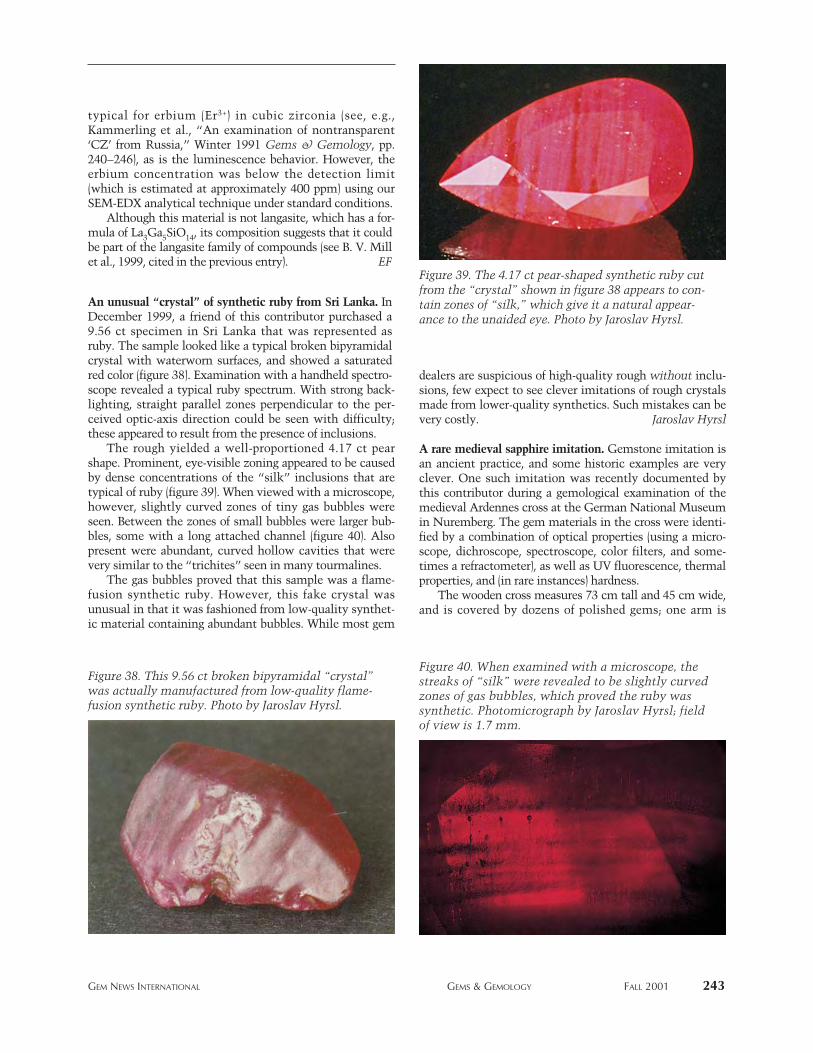
typical for erbium (Er3+) in cubic zirconia (see, e.g.,Kammerling et al., “An examination of nontransparent‘CZ’ from Russia,” Winter 1991 Gems & Gemology, pp.240–246), as is the luminescence behavior. However, theerbium concentration was below the detection limit(which is estimated at approximately 400 ppm) using ourSEM-EDX analytical technique under standard conditions.
Although this material is not langasite, which has a for-mula of La3Ga5SiO14, its composition suggests that it couldbe part of the langasite family of compounds (see B. V. Millet al., 1999, cited in the previous entry). EF
An unusual “crystal” of synthetic ruby from Sri Lanka. InDecember 1999, a friend of this contributor purchased a9.56 ct specimen in Sri Lanka that was represented asruby. The sample looked like a typical broken bipyramidalcrystal with waterworn surfaces, and showed a saturatedred color (figure 38). Examination with a handheld spectro-scope revealed a typical ruby spectrum. With strong back-lighting, straight parallel zones perpendicular to the per-ceived optic-axis direction could be seen with difficulty;these appeared to result from the presence of inclusions.
The rough yielded a well-proportioned 4.17 ct pearshape. Prominent, eye-visible zoning appeared to be causedby dense concentrations of the “silk” inclusions that aretypical of ruby (figure 39). When viewed with a microscope,however, slightly curved zones of tiny gas bubbles wereseen. Between the zones of small bubbles were larger bub-bles, some with a long attached channel (figure 40). Alsopresent were abundant, curved hollow cavities that werevery similar to the “trichites” seen in many tourmalines.
The gas bubbles proved that this sample was a flame-fusion synthetic ruby. However, this fake crystal wasunusual in that it was fashioned from low-quality synthet-ic material containing abundant bubbles. While most gem
dealers are suspicious of high-quality rough without inclu-sions, few expect to see clever imitations of rough crystalsmade from lower-quality synthetics. Such mistakes can bevery costly. Jaroslav Hyrsl
A rare medieval sapphire imitation. Gemstone imitation isan ancient practice, and some historic examples are veryclever. One such imitation was recently documented bythis contributor during a gemological examination of themedieval Ardennes cross at the German National Museumin Nuremberg. The gem materials in the cross were identi-fied by a combination of optical properties (using a micro-scope, dichroscope, spectroscope, color filters, and some-times a refractometer), as well as UV fluorescence, thermalproperties, and (in rare instances) hardness.
The wooden cross measures 73 cm tall and 45 cm wide,and is covered by dozens of polished gems; one arm is
GEM NEWS INTERNATIONAL GEMS & GEMOLOGY FALL 2001 243
Figure 38. This 9.56 ct broken bipyramidal “crystal”was actually manufactured from low-quality flame-fusion synthetic ruby. Photo by Jaroslav Hyrsl.
Figure 39. The 4.17 ct pear-shaped synthetic ruby cutfrom the “crystal” shown in figure 38 appears to con-tain zones of “silk,” which give it a natural appear-ance to the unaided eye. Photo by Jaroslav Hyrsl.
Figure 40. When examined with a microscope, thestreaks of “silk” were revealed to be slightly curvedzones of gas bubbles, which proved the ruby wassynthetic. Photomicrograph by Jaroslav Hyrsl; fieldof view is 1.7 mm.
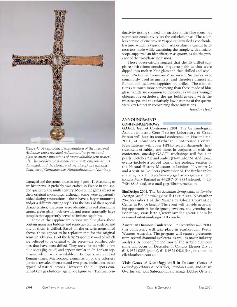
damaged and the stones are missing (figure 41). According toart historians, it probably was crafted in France in the sec-ond quarter of the ninth century. Most of the gems are set intheir original mountings, although some were apparentlyadded during restorations—these have a larger mountingand/or a different cutting style. On the basis of their opticalcharacteristics, the gems were identified as red almandinegarnet, green glass, rock crystal, and many unusually largesamples that apparently served to imitate sapphires.
Three of the sapphire imitations are blue glass; thesecontain many gas bubbles and scratches on the surface, andone of them is drilled. Based on the criteria mentionedabove, these appear to be replacements for the originalgems. In addition, 15 of the large “sapphires”—all of whichare believed to be original to the piece—are polished peb-bles that have been drilled. They are colorless with a fewblue spots (figure 42) and appear similar to Sri Lankan sap-phires, which were available in Europe since at leastRoman times. Microscopic examination of the colorlessportions revealed fractures and two-phase inclusions, as aretypical of natural stones. However, the blue spots con-tained tiny gas bubbles (again, see figure 42). Thermal con-
ductivity testing showed no reaction on the blue spots, butsignificant conductivity on the colorless areas. The color-less portion of one broken “sapphire” revealed a conchoidalfracture, which is typical of quartz or glass; a careful hard-ness test made while examining the sample with a micro-scope supported an identification as quartz, as did the pres-ence of the two-phase inclusions.
These observations suggest that the 15 drilled sap-phire imitations consist of quartz pebbles that weredipped into molten blue glass and then drilled and repol-ished. (Note that “gemstones” in ancient Sri Lanka werecommonly used as amulets, and therefore almost allRoman and medieval sapphires are drilled.) These imita-tions are much more convincing than those made of blueglass, which are common to medieval as well as youngerobjects. Nevertheless, the gas bubbles seen with themicroscope, and the relatively low hardness of the quartz,were key factors in recognizing these imitations.
Jaroslav Hyrsl
ANNOUNCEMENTS CONFERENCES/SHOWSGAGTL Gem-A Conference 2001. The GemmologicalAssociation and Gem Testing Laboratory of GreatBritain will host its annual conference on November 4,2001, at London’s Barbican Conference Centre.Presentations will cover HPHT-treated diamonds, heattreatment of rubies, and more. In conjunction with theconference, one-day GAGTL workshops will focus onpearls (October 31) and amber (November 6). Additionalevents include a guided tour of the geologic section ofthe Natural History Museum in London (November 2)and a visit to De Beers (November 5). For further infor-mation, visit http://www.gagtl.ac.uk/gnews.htm; contact Mary Burland at 44-20-7404-3334 (phone), 44-20-7404-8843 (fax); or e-mail [email protected].
SimDesign 2001. The 1st Brazilian Symposium of JewelryDesign and Gemology will take place November29–December 1 at the Marina da Glória ConventionCenter in Rio de Janeiro. The event will provide network-ing opportunities for designers, jewelers, and gemologists.For more, visit http://www.simdesign2001.com.br or e-mail [email protected].
Australian Diamond Conference. On December 4–5, 2000,this conference will take place in Scarborough, Perth,Western Australia. The program will feature presentersfrom several diamond explorers, as well as major industryanalysts. A pre-conference tour of the Argyle diamondmine will occur on December 1. Contact Eleanor Dix at61-8-9321-0355 (phone), 61-8-9321-0426 (fax), or e-mail [email protected].
Visit Gems & Gemology staff in Tucson. Gems &Gemology editors Alice Keller, Brendan Laurs, and StuartOverlin will join Subscriptions manager Debbie Ortiz at
244 GEM NEWS INTERNATIONAL GEMS & GEMOLOGY FALL 2001
Figure 41. A gemological examination of the medievalArdennes cross revealed red almandine garnet andglass or quartz imitations of more valuable gem materi-als. The wooden cross measures 73 ¥ 45 cm; one arm isdamaged, and the stones and metalwork are missing.Courtesy of Germanisches Nationalmuseum Nürnberg.
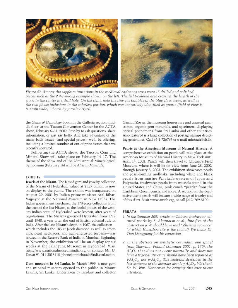
the Gems & Gemology booth in the Galleria section (mid-dle floor) at the Tucson Convention Center for the AGTAshow, February 6–11, 2002. Stop by to ask questions, shareinformation, or just say hello. And take advantage of themany back issues—and special prices—we’ll be offering,including a limited number of out-of-print issues that werecently acquired.
Following the AGTA show, the Tucson Gem andMineral Show will take place on February 14–17. Thetheme of the show and of the 23rd Annual MineralogicalSymposium (February 16) will be African Minerals.
EXHIBITSJewels of the Nizam. The famed gem and jewelry collectionof the Nizam of Hyderabad, valued at $1.27 billion, is nowon display to the public. The exhibit was inaugurated onAugust 29, 2001 by Indian prime minister Atal BihariVajpayee at the National Museum in New Delhi. TheIndian government purchased the 173-piece collection fromthe trust of the last Nizam, as the feudal princes of the west-ern Indian state of Hyderabad were known, after years ofnegotiations. The Nizams governed Hyderabad from 1712until 1948, a year after the end of British colonial rule ofIndia. After the last Nizam’s death in 1967, the collection—which includes the 185 ct Jacob diamond as well as emer-alds, pearl necklaces, and gem-encrusted turbans—washoused in the Reserve Bank of India in Mumbai. Beginningin November, the exhibition will be on display for sixweeks at the Salar Jung Museum in Hyderabad. Visithttp://www.nationalmuseumindia.org, or contact Mr. U.Das at 91-011-3018415 (phone) or [email protected].
Gem museum in Sri Lanka. In March 1999, a new gemand mineral museum opened to the public in MountLavinia, Sri Lanka. Undertaken by lapidary and collector
Gamini Zoysa, the museum houses rare and unusual gem-stones, organic gem materials, and specimens displayingoptical phenomena from Sri Lanka and other countries.Also featured is a large collection of postage stamps depict-ing gemstones. Call 94-1-726796 or e-mail [email protected].
Pearls at the American Museum of Natural History. Acomprehensive exhibition on pearls will take place at theAmerican Museum of Natural History in New York untilApril 14, 2002. Pearls will then travel to Chicago's FieldMuseum, where it will be on view from June 28, 2002,through January 5, 2003. The exhibition showcases pearlsand pearl-forming mollusks, including white and blackpearls from marine Pinctada oysters of Japan andPolynesia, freshwater pearls from mussels found in theUnited States and China, pink conch “pearls” from theCaribbean Queen conch, and more. A section on the deco-rative use of pearls will feature a wide range of jewelry andobjets d’art. Visit www.amnh.org, or call (212) 769-5100.
ERRATA1. In the Summer 2001 article on Chinese freshwater cul-
tured pearls by S. Akamatsu et al., line five of theabstract on p. 96 should have read “Zhejiang Province”(of which Hangzhou city is the capital). We thank Dr.Tian Liangguang for this correction.
2. In the abstract on synthetic corundum and spinelfrom Skawina, Poland (Summer 2001, p. 170), theAl2O3 that does not occur naturally and does nothave a trigonal structure should have been reported asg-Al2O3, not a-Al2O3. The material described in thelast sentence of the abstract also is g-Al2O3. We thankDr. W. Wm. Hanneman for bringing this error to ourattention.
GEM NEWS INTERNATIONAL GEMS & GEMOLOGY FALL 2001 245
Figure 42. Among the sapphire imitations in the medieval Ardennes cross were 15 drilled and polishedpieces such as the 2.4-cm-long example shown on the left. The light-colored area crossing the length of thestone in the center is a drill hole. On the right, note the tiny gas bubbles in the blue glass areas, as well asthe two-phase inclusions in the colorless portion, which was tentatively identified as quartz (field of view is8.0 mm wide). Photos by Jaroslav Hyrsl.
246 BOOK REVIEWS GEMS & GEMOLOGY FALL 2001
Gemstones—Quality andValue, Vol. 3: JewelryBy Yasukazu Suwa, 144 pp., illus.,publ. by Sekai Bunka Publishing,Tokyo, 2001. US$95.00*
This beautifully illustrated and de-signed book helps explain “the factorsthat determine the quality of jewelry”in a way that most readers will under-stand and appreciate. Mr. Suwa accom-plishes this by separating the bookinto two main sections. In the first,“Gemstone-Oriented Jewelry,” heexamines 26 individual pieces of jew-elry and explains the features thatmake each one unique and desirable.He then focuses on specific aspects ofeach jewel in an educational formatthat teaches the reader what to lookfor in similar jewelry. For example, thechapter on a “band-type emerald anddiamond ring” explains why the dia-monds are set in platinum while theemerald is set in gold (because eachmetal flatters the color of the particu-lar stone). Mr. Suwa further adds thatthe emerald in the ring is fromZambia and is untreated. In the nextfew pages of the chapter, he movesinto a more general discussion oftreated vs. untreated emeralds and theversatility of band rings.
The second section, “The Qualityof Jewelry,” is especially informativefor those unfamiliar with the jewelrytrade. Here Mr. Suwa reviews quality,value, and price. He also takes the read-er through design conception, choice ofmaterials, fabrication, evaluation of thejewelry’s condition (porosity, soldermarks, etc.), remodeling, and recircula-tion (resale). Diagrams illustrate vari-ous jewelry parts. The book finisheswith a chapter on trends and traditions,and a useful jewelry glossary.
As a reference, this volume accom-plishes much. The areas discussed arewell illustrated and organized, and aconvenient section on “How to UseThis Book” is included. Rather thanjust deal with a particular type of set-ting, stone, or style, Gemstones: Qual-ity and Value achieves distinction bytaking actual pieces of jewelry andteaching the reader how to evaluatethem. As the author clearly states, thebook is not a technical manual.However, it does succeed as anoverview. At the very least, it will givethe reader a deep appreciation for jew-elry of quality.
JANA E. MIYAHIRA-SMITHGemological Institute of America
Carlsbad, California
Mogôk: Valley ofRubies & SapphiresBy Ted Themelis, 270 pp., illus.,publ. by A & T Publishing, LosAngeles, 2000. US$89.00
This reviewer has anxiously awaitedTed Themelis’s Mogok book for morethan two years. When I saw a copy atthe 2001 Las Vegas JCK show, I knewthat my long wait was justified. Fromthe pleasing dust jacket through theplethora of maps, drawings, and pho-tographs both old and new, it wasobvious that the author’s love forMogok and Burma (now Myanmar)had been transferred to the pages ofthis book. This hardcover book mea-sures 22 ¥ 29 cm (8.6 ¥ 11.4 inches),and has more than 500 illustrations.
Chapter 1 covers the history ofBurma. As complicated as that histo-ry might be, Mr. Themelis managesto make it both understandable and
accurate. Sidebars of interesting leg-ends, together with the pictures andgraphics, hold the reader’s attentioneven through complex dynasticnames and tongue-twisting transliter-ations from Burmese into English.
In the following three chapters, Mr.Themelis plunges directly into the cul-tural melting pot that is Mogok, cover-ing the town’s varied lifestyles, reli-gions, cuisines, and superstitions.While some readers may find certaindetails unnecessary, many of themrelate back to the gems themselves.
Gem trading from early times tothe present day is covered in chapter 5,and chapter 6 examines how the lapi-daries of Burma and Mogok havechanged over the years, with influencefrom Indian, British, and most recentlyThai lapidaries. An interesting expla-nation of why Burmese cutters leaveextra weight on their stones is provid-ed (i.e., not just for higher weight yield,but also so subsequent buyers canimprove the stone if they desire).
Chapter 7 covers notable rubiesand sapphires from Mogok, and in-cludes a wonderful story on a majorpiece of rough that eventually pro-duced a 25.55 ct faceted ruby. How-ever, the tables that list major stonesproduced from 1630 to 1999 containmany stories with little substance orsubstantiation. For example, an itemon page 229 reads: “1928. A 437-caratblue sapphire was found in an unspec-
2001Book REVIEWS
EDITORSSusan B. JohnsonJana E. Miyahira-Smith
*This book is available for purchasethrough the GIA Bookstore, 5345Armada Drive, Carlsbad, CA 92008.Telephone: (800) 421-7250, ext.4200; outside the U.S. (760) 603-4200. Fax: (760) 603-4266.
BOOK REVIEWS GEMS & GEMOLOGY FALL 2001 247
ified area of Mogok. It was valued atover £11,000.” Even though mysteryand intrigue are a big part of the gembusiness, items such as this still leavethe reader wishing for more solidinformation.
“Burmese Court Regalia” is thesubject of chapter 8, with an interest-ing account of how so many valuablepalace rubies and other gems disap-peared the night of November 28,1885, when the British occupiedMandalay. The British returned sever-al items, but retained others.
Chapter 9 contains numerousexamples of Burmese jewelry, in bothtraditional and modern settings. Con-cluding the book is a four-page select-ed bibliography, a one-page glossary,and an index.
Mogôk lacks information on geol-ogy, mineralogy, and specific miningareas, as well as pictures of rough.According to the author, however,these topics will be covered in thesecond volume, which this reviewereagerly awaits.
This book’s main flaws are thosefound in many self-published produc-tions. It lacks professional editing andpolish. Numerous errors in spelling,grammar, and traditional publishingsymbols are found throughout thebook. Many photos and plates lackcredit information (e.g., p. 203), andmany statements lack references (e.g.,pp. 12–13). These diminish the valueof a book that is aimed, at least in part,at an academic audience. Anotherserious defect is seen in the photoreproduction. All of the book’s photosshould have been sharpened in thepre-press stage, and virtually all haveunnatural color casts.
However, such distractions areminor when compared to the overallvalue of the work. Since his first visitto Mogok in 1996, Mr. Themelis hasimmersed himself in everythingBurmese and, especially, Mogok. Thisincluded travel to the British Libraryin London, private libraries, variousmuseums, and, of course, the areaitself. The author’s impassioned loveof Mogok provides insights not foundin any other modern book on thisregion. Mogôk—Valley of Rubies &
Sapphires is a must for every gemolo-gist’s library. It captures all aspects ofMogok’s gem and jewelry industry—the history, romance, intrigue and,most importantly, the enchantmentof a truly enchanted land.
WILLIAM F. LARSONPala International
Fallbrook, California
Southwest Silver JewelryBy Paula A. Baxter, 212 pp., illus.,publ. by Schiffer Publishing,Atglen, PA, 2001. US$49.95
When an author writes about a sub-ject he or she loves, it really reachesthe reader. Such is the case with thisbeautiful book, which examines andpays tribute to the first century ofNavajo and Pueblo metal jewelrymaking in the American Southwest.The historical information is enlight-ening, and is complimented by thehigh-quality presentation and numer-ous large-format photos that illus-trate the evolution of this jewelry.
Telling a story that starts in the1860s, the author points out that theuse of silver for jewelry was a rela-tively recent development for NativeAmericans. Metals were not consid-ered to be “spiritual” materials, butthe natives loved the pale luster of sil-ver because it reminded them of themoon. Early work involved the melt-ing of coins to make practical items(such as buttons and belt buckles) andobjects for personal adornment.When these items were seen by thewhite settlers and Native Americansboth locally and from other regions, acommercial market slowly began todevelop. This book recounts the fasci-nating tale of how ingenious NativeAmericans created tools out of avail-able materials after learning skillsfrom blacksmiths and Mexican sil-versmiths, and how each tribebranched off to create a unique stylethat continues to evolve.
Silversmithing production steadi-ly expanded during the “first phase”(1868–1900) of Southwestern Indianjewelry. At first, the techniques werecrude due to the tools available, but as
lapidary work developed and skillswere perfected, more complex designsbegan to appear. Stones first appearedin the silver jewelry around the 1880s,usually as a single polished center-piece mounted in a bezel. The firstgems used were small pieces of localgarnets, turquoise, malachite, or shell.Since the supply of turquoise was ini-tially scarce, traders imported Persianturquoise to meet demand. By 1900,however, new mines in the south-western U.S. yielded plentiful sup-plies. Photos in the book show thetransition from simple early designsto beautiful and intricate works ofmodern art.
The book also helps readers distin-guish the work of the Navajo, Zuni,and Hopi tribes. It clearly explainsterms such as old pawn vs. deadpawn, and it includes tips for collect-ing, a list of prestigious pre-1970Indian artists, and a value referenceguide. The pricing guide is under-standably vague, since most of thehand-wrought items are unique andtheir age or origin is frequently diffi-cult to determine. Nevertheless, thisguide provides a good starting pointfor establishing values. Readers willlearn to better recognize authenticIndian jewelry and to appreciate theart and designs, which are ever-chang-ing but at the same time are alwaysreturning to—and honoring—theirpast. The enthusiasm of the author isinfectious, and leaves the reader want-ing to take a trip to the Southwest insearch of silver treasures.
MARY MATHEWSGemological Institute of America
Carlsbad, California
Jewelry Wax Modeling—A Practical Guide for theJewelry Model MakerBy Adolfo Mattiello, 161 pp., illus.,publ. by Du-Matt Corp., Gutten-berg, NJ, 1999. US$38.95*
This is an excellent book for someonewho wants to get started or learnmore about the art of wax carving.Descriptions of 11 ring projects are
designed to take the reader from thevery basics to the very advanced. Atthe beginning of each project is abeautiful painted rendering of thedesign, accompanied by photos of theactual wax at different stages. The in-depth, step-by-step instructions—with nicely done graphics and mea-surements—make the lessons veryeasy to follow and understand.
This guide is filled with manyunique and time-saving tricks and tips.In addition, it includes a few tool mod-ifications that will help the readerachieve higher levels of craftsmanship.
Many of the projects contain stone-setting styles that involve skills thatare considered rather advanced, such aspavé work and channel setting withbaguettes and round stones. It wouldbe helpful to have some previousstone-setting skill and experience. Ifyou do not, the author recommendsthat you do the prep work for the stonesetting, finish the ring in metal, andthen seek the assistance of a good stonesetter. This should be seen as a chal-lenge rather than a discouragement.
With patience and determination,the reader can learn a great deal fromthis book.
LARRY LAVITTGemological Institute of America
Carlsbad, CA
Western Queensland Opals—Exploration and GeoscienceData SetsCD-ROM, Queensland Govern-ment Department of Mines andEnergy, 2000, free of charge [e-mail:[email protected]].
Geographic information systems(GIS) provide a new, powerful way tolook at spatial data such as geology,gem and mineral occurrences, andland status. This CD-ROM providesan extensive set of data for opal occur-rences in the Cretaceous sedimentaryrocks of western Queensland, Aus-tralia. Also included are several shortHTML (Web browser) files that sum-marize the contents of the CD, intro-duce opal in western Queensland,note sapphire and chrysoprase occur-rences in Queensland, and give relatedinformation on noncommercial col-lecting (fossicking) regulations. Thetext on opals is a few pages long, withonly two illustrations, but, unfortu-nately, it is not integrated into the GISdata sets. The latter are quite extensive,with information on geology, struc-ture, opal occurrences, land status,regional geophysics, and topography.
The CD is simple to use. It opensimmediately with a Web browser run-ning under Windows 95 or higher (in
my case, Windows 98 under VirtualPC on a Macintosh). The GIS data setsare in ESRI ArcView and MapInfo for-mats, which are suited to regular GISusers. In addition, a stand-alone view-er, ArcExplorer, is included along witheasy-to-follow instructions.
As a geologist and teacher, I foundthe data sets and background quiteinteresting, but the information onopals is rather thin. This CD would beof interest to those prospecting in orvisiting western Queensland opal dis-tricts. On the other hand, it has littleto offer for those primarily interestedin the gemology or detailed geology ofthese occurrences. Nevertheless, theQueensland Department of Minesand Energy is to be commended forpublishing this CD-ROM; there is acoming revolution in the use of elec-tronic publication with incorporationof approaches such as GIS that simplycannot be done in print.
MARK D. BARTONDepartment of Geosciences
University of Arizona, Tucson
Correction: The Summer 2001 BookReviews section listed the retail price ofThe Practical Guide to Jewelry Appraisingby Cos Altobelli as $49.95. This price is forAGS members only. The actual retail priceis $64.95.
248 BOOK REVIEWS GEMS & GEMOLOGY FALL 2001
COLORED STONES ANDORGANIC MATERIALSChinese pearls: Their culturing and trading. Guo T., Australian
Gemmologist, Vol. 20, No. 11, 2000, pp. 486–490.Chinese freshwater cultured pearls are playing an increasinglyimportant role in the industry. In the 1960s, the cultivation wasdone primarily by individual families or indigenous farmers. Inrecent years, however, pearl culturing has shifted to large, mod-ernized farms and the use of different mollusks, resulting inlarge quantities of a highly desirable product. In 1999, globalproduction of cultured pearls was estimated at 1,262 tons, withChinese freshwater cultured pearls making up 1,000–1,200 tonsof that amount. Most of the farms are located along the banksof the Chang Jiang (Yangtze) River, where more than 400,000people are engaged in the pearling industry. After 2–5 years ofpropagation and 1– 3 years of cultivation, the implanted mus-sels produce jewelry-grade cultured pearls in a range of shapes(mostly off-round and baroque) and colors; most undergo colortreatment before being sold. Luster ranges from poor to excel-lent, with larger cultured pearls (over 10 mm in diameter) typi-cally showing low luster.
In the last two decades, the coastline of the GuangxiProvince (Hepu and nearby areas) in southern China, includingHainan Island, has been used for the culturing of saltwaterpearls. Natural pearls have been known from these areas sincethe Qin and Han Dynasties (221 BC to 221 AD). About 15–20tons of Chinese Akoya cultured pearls were produced in 1999.The Beihai Municipal Bureau of Technical and QualitySupervision has dictated standards for Chinese Akoya pearl cul-tivation, with the objective of improving quality. These stan-dards include specifications for the condition and depth of the
Gemological ABSTRACTS
2001EDITOR
A. A. LevinsonUniversity of Calgary
Calgary, Alberta, Canada
REVIEW BOARD
Anne M. BlumerBloomington, Illinois
Jo Ellen ColeGIA Museum Services, Carlsbad
R. A. HowieRoyal Holloway, University of London
Jeff LewisUniversity of New Orleans, Louisiana
Taijin LuGIA Research, Carlsbad
Wendi M. MayersonGIA Gem Trade Laboratory, New York
Kyaw Soe MoeGIA Gem Trade Laboratory, Carlsbad
Joshua ShebyGIA Gem Trade Laboratory, New York
James E. ShigleyGIA Research, Carlsbad
Jana E. Miyahira-SmithGIA Education, Carlsbad
Maha TannousGIA Gem Trade Laboratory, Carlsbad
Rolf Tatje Duisburg University, Germany
Lila TaylorSanta Barbara, California
Paige TullosGIA Gem Trade Laboratory, Carlsbad
Sharon WakefieldNorthwest Gem Lab, Boise, Idaho
Philip G. YorkGIA Education, Carlsbad
This section is designed to provide as complete a record as pra-ctical of the recent literature on gems and gemology. Articles areselected for abstracting solely at the discretion of the section edi-tor and his reviewers, and space limitations may require that weinclude only those articles that we feel will be of greatest interest to our readership.
Requests for reprints of articles abstracted must be addressed to the author or publisher of the original material.
The reviewer of each article is identified by his or her initials at theend of each abstract. Guest reviewers are identified by their fullnames. Opinions expressed in an abstract belong to the abstrac-ter and in no way reflect the position of Gems & Gemology or GIA.
© 2001 Gemological Institute of America
GEMOLOGICAL ABSTRACTS GEMS & GEMOLOGY FALL 2001 249
water, characteristics of the basket in which the seededmussels are housed, techniques for implantation, andminimum cultivation times. Some of the large saltwaterfarms are attempting to improve the quality of their cul-tured pearls by implementing crossbreeding, low-densityfarming, and better processing technology. In size andquality, Chinese Akoya cultured pearls still do not matchtheir Japanese counterparts, which sell for significantlymore. Chinese Akoyas also are routinely color treated:bleached and then dyed. MT
Emerald deposits—A review. D. Schwarz and G. Giuliani,Australian Gemmologist, Vol. 21, No. 1, 2001, pp.17–23.
Emerald is relatively rare because its chromophoric ele-ments, Cr and V, are not typically associated with Be.Sources of Cr and V are mafic-ultramafic igneous rocks andblack shales, whereas Be occurs in granitic magmas, blackshales, and metamorphic rocks. The principal mechanismresponsible for emerald crystallization is fluid–rock inter-action, which allows the combination of these geochemi-cally incompatible elements.
Most emerald deposits are associated with graniticintrusions and their related hydrothermal processes; exam-ples include most African and Brazilian deposits, as wellas those in the Ural Mountains of Russia. A second typeof emerald formation is not directly related to graniticintrusions, but rather results from the circulation of fluidsalong regional tectonic structures (thrust faults and shearzones), as at Santa Terezinha in Brazil and the Swat Valleyin Pakistan. The famous Colombian emerald depositshave a unique formation through the thermochemicalreduction of evaporitic sulfate brines, with organic matterfrom the surrounding black shales participating in thereactions. RAH
The factors for restricting quality of Chinese pearl. Y.Deng and K. Yuan, Journal of Guilin Institute ofTechnology, Vol. 21, No. 1, 2001, pp. 6–12 [inChinese with English abstract].
This article summarizes the results of research on Chinesesaltwater cultured pearls of various grades, from differentlocalities. Basic gemological properties were determined,and analytical data were obtained using (1) X-ray diffrac-tion to determine mineral composition, and (2) ICP-AES(inductively coupled plasma–atomic emission spec-troscopy) to determine trace elements and organic com-ponents present in these cultured pearls. The density ofhigh-quality cultured pearls from Hepu (GuangxiProvince) was 2.76 g/cm3, whereas low-quality culturedpearls had a density of 2.69 g/cm3. Although Chinese salt-water cultured pearls are composed predominantly ofaragonite crystals, significant calcite (10%–45%) is alsopresent. As is the case for most pearls (both natural andcultured), the c-axes of the aragonite crystals are orientedradially from the center of the cultured pearls. Studies of
the mineral composition, colors and their distribution,impurities, and internal growth features of Chinese salt-water cultured pearls revealed that these features could becorrelated to different growth environments. TL
Gem tourmaline chemistry and paragenesis. W. B. Sim-mons, K. L. Webber, A. U. Falster, and J. W. Nizamoff,Australian Gemmologist, Vol. 21, No. 1, 2001, pp.24–29.
Gem tourmalines from six pegmatite mining areas werestudied by electron microprobe (no actual analyses aregiven). The samples were from Transbaikalia (Siberia,Russia), central Madagascar (Antandrokomby and Fiana-rantsoa/Anjanabonoina), Paraíba (Brazil), and the U.S.(Dunton, Maine, and the Himalaya mine in California).All were found to be dominantly elbaite or liddicoatite,with the darker varieties having a minor schorl compo-nent. Y-site chemistry correlated strongly with color andappeared to be influenced by the chemistry of the parentpegmatites. X-site vacancies were <0.3 atoms per formu-la unit (apfu).
The principal chromophores in the study samples wereidentified as Fe, Mn, Ti, and Cu. The pink and green tour-malines from Transbaikalia were essentially elbaite, butyellow zones in these crystals revealed a substantial liddi-coatite component and elevated levels of Ti and Mn.Samples from Fianarantsoa/Anjanabonoina were liddicoat-ite. The Antandrokomby tourmalines belonged to theschorl-elbaite series, with significant Mg and Ca; theyrevealed the lowest Y-site Al content as well. The Maineand California tourmalines also were schorl-elbaite, withthe lighter-colored gem varieties approaching end-memberelbaite. The Paraíba tourmalines were elbaite, colored avivid blue by Cu (0.1–0.3 apfu) in the Y-site. RAH
The genetic relation between good-quality jadeite andmicrostructure. K. Yuan and Y. Deng, Journal ofGuilin Institute of Technology, Vol. 21, No. 1,2001, pp. 1–5 [in Chinese with English abstract].
This well-illustrated article summarizes recent studiesrelating the quality of jadeite to microstructural charac-teristics that result from various geologic processes. Low-quality jadeite is correlated to cataclastic textures (char-acterized by bending and breaking) that are produced bysevere mechanical stresses during metamorphism. Good-quality material is associated with mylonitic textures,which are characterized by intense microbrecciation andshearing. The highest-quality jadeite forms via “dynamicrecrystallization” under conditions of low temperature,with strong shear stress and high strain velocity accom-panying ductile deformation. Such jadeites have a fine-grained texture and good transparency. Green in jadeite iscaused by the release of Cr from associated or includedchromite grains; the intensity of the color appears to berelated to the degree and type of structural deformation.
TL
250 GEMOLOGICAL ABSTRACTS GEMS & GEMOLOGY FALL 2001
Jade: Occurrences and metasomatic origin. G. E. Harlowand S. S. Sorensen, Australian Gemmologist, Vol.21, No. 1, 2001, pp. 7–10.
A brief review is given of the nephrite and jadeite varietiesof jade and their occurrence. Nephrite, the more commonvariety, is formed via contact metasomatism of dolomiteby magmatic fluids (at <550°C), or of silicic rocks by ser-pentinite-derived fluids (~100° to ~400°C) in ophiolites atmoderate to low pressure (<2 kbar?). Jadeite is much rarerand forms only in subduction-related serpentinites alongmajor fault zones at 200°–400°C and at high pressure(>5–6 kbar). Thus, most jade deposits record events atconvergent plate margins that involve fluid interactions inand around serpentinizing peridotite. RAH
Micro-analytical study of the optical properties of rain-bow and sheen obsidians. C. Ma, J. Gresh, G. R.Rossman, G. C. Ulmer, and E. P. Vicenzi, CanadianMineralogist, Vol. 39, 2001, pp. 57–71.
Samples of Mexican obsidian that exhibit “sheen” or“rainbow” optical properties were studied by a combina-tion of micro-analytical (e.g., scanning electron micro-scope) and microscopic (e.g., thin-section) techniques toexplain the cause of these phenomena.
The sheen (single color, usually a velvety “silver” or“gold”) is attributed to the presence of gas- and glass-filledflow-aligned areas in the obsidian. These areas have dif-ferent chemical (e.g., lower SiO2) and optical (e.g., lowerrefractive index) properties compared to the matrix. Thedifference in R.I. (by as much as 0.04) leads to opticalinterference, hence sheen, along the interfaces betweenthe two glasses.
There are two types of rainbow obsidian, so-calledbecause of the bands of various colors ranging from redthrough purple. Both are trachytic, in that they have sub-parallel elongate crystallites in the groundmass. One typecontains rods of hedenbergite (a clinopyroxene), and theother has rods of feldspar. The two types are mutuallyexclusive; they do not occur together. The matrix glassesof the two types have nearly identical and uniform refrac-tive indices and composition, so the rainbow effect is notattributed to these parameters. However, the differencesin R.I. between the matrix and the crystallites in bothtypes of rainbow obsidian result in the scattering of whitelight. Thus, the arrays of crystallites—and in particulartheir sizes and shapes—serve to produce a thin-film inter-ference, which is the preferred explanation for the rain-bow effect. AAL
Origin of gem corundums from basaltic fields. F. L.Sutherland and D. Schwarz, Australian Gemmolo-gist, Vol. 21, No. 1, 2001, pp. 30–33.
Gem corundum is widely formed as xenocrysts in basalticrocks; that is, the crystals form deep in the earth and are“picked up” from that environment by the basalticmagma that carries them to the surface. Such corundum
has been recorded from six continental regions, within 15countries, involving some 40 main basalt fields—whichthis article tabulates, along with their ages of eruption.Two corundum suites are differentiated: (1) blue, green,and yellow color-zoned “magmatic” sapphires that arethought to have formed by igneous crystallization in theearth’s crust or mantle; and (2) variously colored “meta-morphic” sapphires and rubies from deep-seated meta-morphic source rocks. Magmatic suites (which make up60% of the basaltic sapphires) dominate over mixed mag-matic/metamorphic suites (25%) and metamorphic suites(15%). Zircons found in the same deposits yield U–Pb iso-tope formation ages that are presumed to be the ages ofsapphire crystallization. These ages are usually close tothose determined for the associated basalts. RAH
Production and colour changing treatment of Chinesecultured pearl. L. Li, Singaporean Gemologist, Vol.8, No. 1, 2001, pp. 11–14.
Recently, Chinese pearl farmers and dealers have beenexperimenting with various aspects of cultured pearl pro-duction, not just the shape of the final product and thematerial used for nuclei (e.g., wax, aluminum), but alsocolor manipulation. There are two fundamental types ofcolor treatment: dyeing and gamma-ray irradiation. Alsomentioned is a new “lasering” technique, which pro-duces dark “peacock” green and purple colors.
A short description of methods for detecting dye treat-ment is provided. These include: (1) color distribution(e.g., color patches on the surface, or concentration ofcolor in and near the drill hole); (2) fluorescence (treated-colored samples typically show anomalous fluorescenceor are inert); (3) Raman spectrometry (the presence of spe-cific weak peaks); and (4) chemical testing (alcohol/ace-tone removes some dyes). Irradiation may turn the cul-tured pearls green, black, “silver,” dark red, or “bronze.”It may also increase the sample’s susceptibility to frac-turing just below the surface and around the drill hole. Aslight decrease in S.G. and hardness may also occur inirradiated freshwater cultured pearls. JS
Raman spectra of nacre from shells of main pearl-cultur-ing mollusk in China. G. Zhang, X. Xie, and Y.Wang, Spectroscopy and Spectral Analysis, Vol. 21,No. 2, 2001, pp. 193–196 [in Chinese with Englishabstract].
Cultured pearls in China are grown using four types ofmollusks: Pinctada martensii, Pinctada maxima, andPteria penguin (saltwater); and Hyriopsis cumingi (fresh-water). Aragonite is the main mineral component of thenacre (mother-of-pearl) in shells from all four mollusks.Raman spectrometry was used to study the organic com-ponents in nacre from each mollusk.
The Raman bands related to organic componentswere different in the nacre from each species. Organicmaterial was not observed in the nacre of Pinctada max-
GEMOLOGICAL ABSTRACTS GEMS & GEMOLOGY FALL 2001 251
ima. Two bands resulting from a carotenoid were clearlyidentified in the nacre of Pinctada martensii andHyriopsis cumingi, and the number of C=C double bondsin the molecular structure of this carotenoid was predi-cated to be 10 based on the position of the Raman bands.A number of complicated Raman bands were observed inthe nacre of Pteria penguin; these bands are possiblycaused by metalloporphyrin compounds. There is a closerelationship between the color of the nacre and the rela-tive concentrations of carotenoid and inferred metallo-porphyrin compounds in the nacre layers. TL
DIAMONDSDiamants [Diamonds]. Le Règne Minéral, No. 38, 2001,
66 pp. [in French, with some English abstracts].The fabulous diamond exhibition at the MuséumNational d’Histoire Naturelle in Paris (March 10–July 31,2001) inspired the French mineral collector’s magazine LeRègne Minéral to dedicate a special issue to this gem incooperation with the creators of the exhibition.
The first article, “Le diamant, l’orchidée du règneminéral,” by R. De Ascenção Guedes, surveys the miner-alogical properties of diamond and shows why diamondshold a unique position in the mineral kingdom. The focuslies on crystal structures and forms, which are illustratedby several diagrams as well as crystal drawings from Dana(1871), Goldschmidt (1911), and others.
Next, “Naissance et voyages du diamant” (R. deAscenção Guedes and J.-C. Goujou) describes diamondgeology: the structure of the earth’s interior, conditionsand processes of diamond formation, transport to the sur-face, and types of diamond deposits. This article alsoincludes a comprehensive listing, with short descriptions,of diamond deposits worldwide.
In “Le diamant et ses paradoxes,” J.-C. Goujou describesthe paradoxical nature of the diamond world. This articlecontrasts graphite vs. diamond, the cubic crystal system vs.diamond’s variety of forms, and old diamonds vs. younghost rocks, but it is mostly concerned with the contrastbetween diamond as the paragon of riches and luxury vs.the poverty and sociopolitical problems in many miningareas. The result is a description of the mining histories andpresent-day situations in Angola, Democratic Republic ofCongo (formerly Zaire), Guinea, Liberia, and Sierra Leone.
Three more articles (B. Cairncross—“Les diamantsd’Afrique du Sud, du Botswana et de Namibie”; G. B.Webb and F. L. Sutherland—“Les gisements diaman-tifères Australiens”; J. Cassedanne—“Le diamant auBrésil”) present detailed descriptions of some importantAfrican, Australian, and Brazilian diamond deposits.
The final article, “Contrebande de diamants: affaireSchreiber, Dakar” (J. E. Dietrich), tells the story of 18,000carats of rough diamonds that were seized as contrabandat Dakar’s Yoff Airport in 1956, but had to be returned totheir owner in spite of the obvious crime—an episode usedby Ian Fleming in his book The Diamond Smugglers.
The issue is well illustrated, with many fine colorphotographs of diamonds and diamond mining. RT
Diamond from the Guaniamo area, Venezuela. F. V.Kaminsky, O. D. Zakharchenko, W. L. Griffin, D. M.DeR. Channer, and G. K. Khachatryan-Blinova,Canadian Mineralogist, Vol. 38, 2000, pp. 1347–1370.
The Guaniamo region is an important placer diamondmining area in Venezuela—an estimated 25–30 millioncarats may have been produced since 1968—but the dia-monds have never been studied scientifically. This com-prehensive report, based on more than 5,000 diamondcrystals and fragments from placer and kimberlite silldeposits, characterizes the diamonds in terms of mor-phology, abundance and aggregation state of nitrogen,mineral inclusions, and carbon isotopic composition.
About 50% of the crystals were resorbed dodecahedra;octahedra were the next most abundant form. Most of thediamonds were colorless, but 55%–90% showed someradiation-induced areas of pigmentation. About 20% of thediamonds had very low nitrogen contents (<250 ppm; typeII); the remainder belonged to the transitional type IaAB,with B>A. The mineral inclusions in 86% of the samples(77 were studied) had ecologitic affinity represented by gar-net, omphacite, rutile, ilmenite, and pyrrhotite. Inclusionsof peridotitic affinity were represented by garnet, chromianspinel, and olivine. Values of d13C ranged from –3.2‰ to–28.7‰, but most of the diamonds were isotopically light(d13C less than -10‰), which is also typical of an eclogiticorigin. The high proportion of diamonds with eclogiticcharacteristics, and several features of the mineral inclu-sions, show striking parallels to diamonds from the Argylemine in Australia. Both deposits occur in cratons that havehad extensive Proterozoic tectonothermal activity. Theauthors believe that the Guaniamo placer diamonddeposits are of local origin and were derived from the kim-berlite sills rather than having been recycled from theancient Roraima sediments in the area, as has been previ-ously suggested. AAL
Diamonds from Myanmar and Thailand: Characteristicsand possible origins. W. L. Griffin, T. T. Win, R.Davies, P. Wathanakul, A. Andrew, I. Metcalfe, andP. Cartigny, Economic Geology, Vol. 96, No. 1,2001, pp. 159–170.
Alluvial diamonds (262 samples) from two localities inMyanmar (Theindaw and Momeik) and one in Thailand(Phuket), for which there are no obvious rocks in the areathat might serve as the primary source, were studied inorder to determine their origin. This detailed investigationfound similarities in the physical features of the diamondsfrom both countries—that is, their color (mostly yellowthrough brown), morphology (mostly rounded andresorbed), and surface features (lamination lines reflectingplastic deformation). The inclusions (e.g., olivine,chromite, pyrope) are primarily of peridotitic origin.
252 GEMOLOGICAL ABSTRACTS GEMS & GEMOLOGY FALL 2001
Carbon isotope values (d13C mostly between –3‰ and–8‰) are also consistent with a peridotitic origin. Nitrogenaggregation studies indicate a long residence and/or defor-mation at mantle temperatures; the association of the dia-monds with a corrosive magma is evidenced by theirresorbed shapes. Extensive abrasion and abundant brownspots due to radiation damage suggest appreciable surfacetransport.
These alluvial diamonds (as well as others in Sumatra,Indonesia, which were not studied) are found in theSibumasu geological terrane, which is believed to haveseparated from the ancient Gondwana supercontinent inEarly Permian time (about 275 million years ago). At thetime, Gondwana also included Australia. The diamondsare also closely associated with certain glacial-marine sed-iments of slightly younger age that came from westernAustralia. Hence, it is suggested that these SoutheastAsian diamonds were derived from primary kimberlitesources in northwestern Australia, or within the Sibu-masu terrane itself. However, the predominantly peri-dotitic nature of both the inclusions and the carbon iso-tope data rule out the Argyle lamproite as the primarysource because of its eclogitic paragenesis. AAL
Irradiation-induced structure development in type Ia dia-mond. T. D. Ositinskaya, V. N. Tkach, and G. P.Bogatyreva, Journal of Superhard Materials, Vol.22, No. 1, 2000, pp. 56–60.
Four types of diamonds (natural type Ia, type IaA, andtype IaA/B, and synthetic type IIa) were subjected to setdoses of intense electron irradiation. Cathodolumines-cence (CL) spectroscopy revealed three distinct zones inthe irradiated type Ia diamond. The zone 1 spectrum wascharacterized by peaks at 389 and 575 nm; it stronglyresembled the spectrum derived from the irradiated syn-thetic type IIa diamond. The spectrum of zone 2 wasmost similar to that of the irradiated type 1aA/B dia-mond, which contains a less intense peak at 575 nmalong with peaks at 415, 484.5, and 490.7 nm. Zone 3 wascharacterized by peaks at 484.5, 490.7, and 511.5 nm, aswell as three prominent peaks at 415, 430, and 439 nmthat were not observed in other spectra. The most promi-nent peaks in the irradiated type IaA diamond were at484.5, 490.7, 503.5, and 575 nm. These observations indi-cate that CL spectroscopy may be useful for studying thegenesis of irradiation-induced defects in mixed diamondtypes. Troy Blodgett
GEM LOCALITIESBrazilian gem provinces. C. P. Pinto and A. C. Pedrosa-
Soares, Australian Gemmologist, Vol. 21, No. 1,2001, pp. 12–16.
The principal Brazilian colored gems are aquamarine,alexandrite, emerald, tourmaline, topaz, amethyst, agate,and opal. The main deposits are related to pegmatites
and pneumatolitic-hydrothermal fluids in mafic-ultra-mafic rocks, hydrothermal fluids in metasediments, andvolcanogenic concentrations in continental basalt flows.The main pegmatitic provinces are situated in Neo-proterozoic mobile belts affected by intense graniticintrusion and mineralization. The Be-bearing gems(aquamarine, beryl, chrysoberyl, and alexandrite) aremainly related to these granitic intrusions, which are500–520 million years old. Gem-quality tourmalineoccurs in pegmatites that are related to S-type granites(derived from the partial melting of sedimentary rocks).Emerald occurs in ultramafic schist in the vicinity ofgranitic bodies. The quartz-family gems are related tohydrothermal veins in quartzose rocks, or are found asdruses in Mesozoic basalt flows. RAH
Clinopyroxene–corundum assemblages from alkali basaltand alluvium, eastern Thailand: Constraints on theorigin of Thai rubies. C. Sutthirat, S. Saminpanya,G. T. R. Droop, C. M. B. Henderson, and D. A. C.Manning, Mineralogical Magazine, Vol. 65, No. 2,2001, pp. 277–295.
A clinopyroxene xenocryst with an inclusion of ruby,found in alkali basalt from the Late CenozoicChanthaburi-Trat volcanic rocks of eastern Thailand, waschemically similar to clinopyroxene inclusions in rubiesfrom nearby alluvial gem deposits. This suggests a com-mon origin for both minerals. The clinopyroxene is fairlysodic, highly aluminous, and magnesian; sapphirine andgarnet also occur as inclusions in the alluvial rubies.Thermodynamic calculations constrain the temperatureof clinopyroxene + corundum crystallization to between800° and 1150°C ± 100°C. Other equilibria indicate a pres-sure of crystallization of 10–25 kbar, implying depths offormation between 35 and 88 km. The rubies are pre-sumed to have crystallized in rocks of mafic composition(i.e., garnet clinopyroxenites or garnet pyroclasites) withinthe upper mantle. RAH
Einmalige Tropfsteinbildungen aus Argentinien: Rhodo-chrosit-Stalaktiten [Unique stalactite formations:Rhodochrosite from Argentina]. W. Lieber, Lapis,Vol. 25, No. 11, 2000, pp. 13–20 [in German].
This lavishly illustrated article describes the well-knownCapillitas deposits near Andalgalá, Catamarca Province,Argentina, where rhodochrosite occurs as stalactites morethan 5 m (16 feet) long and up to 50 cm (20 inches) indiameter. The growth conditions of rhodochrosite arecompared to those of “normal” calcite/aragonite stalac-tites. Chemical data are presented for the different bands orlayers of rhodochrosite. The stalactites formed at150°–200°C (whereas calcite stalactites develop below25°C). Contrary to the commonly held belief that the sta-lactites formed within the last 700 years, the authors sug-gest that they are actually 50,000–500,000 years old. RT
GEMOLOGICAL ABSTRACTS GEMS & GEMOLOGY FALL 2001 253
The geology of Australian opal deposits. I. J. Townsend,Australian Gemmologist, Vol. 21, No. 1, 2001, pp.34–37.
Australian opal is mainly hosted in Cretaceous sedimen-tary rocks of the Great Artesian Basin. Silica, derived fromweathering, forms micro-spheres that are deposited in aregular array. Most opaline silica is common opal, orpotch, and does not show a play of color. Opal is oftenfound associated with lineaments or faults, which providepassageways for the movement of groundwater; thesehave proved useful in locating opal at Lightning Ridge inNew South Wales. A climate of alternating wet and dryperiods is important in creating a rising and falling watertable; the silica is deposited when it is concentrated insolution by a receding water table, forming opal in a vari-ety of host materials. RAH
The geology, mineralogy and rare element geochemistryof the gem deposits of Sri Lanka. C. B. Dissanayake,R. Chandrajith, and H. J. Tobschall, Bulletin of theGeological Society of Finland, Vol. 72, No. 1–2,2000, pp. 5–20.
Nearly all the gem-bearing formations of Sri Lanka arelocated in the central high-grade metamorphic terrain ofthe Highland Complex. The gem deposits are classified assedimentary, igneous, and metamorphic, but sedimenta-ry deposits are dominant. The most important gemsinclude corundum, chrysoberyl, beryl, spinel, topaz, zir-con, tourmaline, garnet, and sphene.
Analysis of trace elements in sediments from three gemfields (Ratnapura, Elahera, and Walawe Ganga) revealed thatsome of these sediments are considerably enriched in cer-tain elements compared to their average crustal abun-dances. Sediments from Walawe Ganga are anomalouslyenriched in the high-field-strength and associated ele-ments, particularly Zr, Hf, W, and Ti. This is attributed tothe presence of accessory zircon, monazite, and rutile inthe heavy-mineral fraction, which may constitute up to50% (by weight) of the sediment. The geochemical enrich-ment of some trace elements is taken to indicate thathighly differentiated granites and associated pegmatitesprovided the source material for these sedimentarydeposits. RAH
Oriented inclusions in spinels from Madagascar. K.Schmetzer, E. Gübelin, H-J. Bernhardt, and L.Kiefert, Journal of Gemmology, Vol. 27, No. 4,2000, pp. 229–232.
Lamellar and needle-like inclusions found in six facetedbluish gray spinels (0.15 to 0.50 ct) from southern Mada-gascar are described. The samples were purchased twoyears prior to the discovery (in 1998) of the deposits atIlakaka; their exact origin is unknown. Chemical analyseswere performed on the inclusions in three samples, andRaman spectra were obtained from several included crys-tals in two samples. These data established that the lamel-
lar inclusions are enstatite, MgSiO3. The inclusions areoriented parallel to dodecahedral {110} directions in thehost spinels. According to the authors, enstatite in thisoriented relationship within spinel has not been previous-ly reported. The gemological properties of the sampleswere normal for spinel, and the UV-Vis absorption spectrawere typical for spinels containing iron. WMM
Tourmaline and aquamarine deposits from Brazil. J.César-Mendes, H. Jort-Evangelista, and R. Wegner,Australian Gemmologist, Vol. 21, No. 1, 2001, pp.3–6.
Brazil is one of the world’s largest producers of gem-qual-ity aquamarine and tourmaline, which are found ingranitic pegmatites both in the Oriental Province (>500gem pegmatites) in the states of Minas Gerais, Bahia, andEspírito Santo, and in the Northeastern Province (>50 gempegmatites) in the states of Ceará, Paraíba, and Rio Grandedo Norte. Aquamarine occurs in pegmatites that haveundergone only slight geochemical differentiation; it isassociated with mica, K-feldspar, and quartz. Tourmaline(green, blue, and pink-red, but always rich in the elbaitecomponent) occurs mainly in rare-element-bearing peg-matites with lepidolite, albite, tantalite, and morganite; itvaries in composition depending on its position within thepegmatite. RAH
INSTRUMENTS AND TECHNIQUESNuclear microscopic studies of inclusions in natural and
synthetic emeralds. K. N. Yu, S. M. Tang, and T. S.Tay, X-Ray Spectrometry, Vol. 29, No. 2, 2000, pp.178–186.
Micro-proton-induced X-ray emission (micro-PIXE) spec-tra were obtained from 56 natural emeralds fromColombia, Pakistan, Zambia, Brazil, and 26 syntheticemeralds from eight manufacturers using flux andhydrothermal growth techniques. These spectra wereused to study mineral and other types of inclusions (suchas flux residues) as well as chemical variations that couldbe correlated to color zoning.
Five flux-grown synthetic emeralds (Chatham) andone hydrothermal (Lechleitner) sample yielded nearly fea-tureless spectral data; such was not the case for the natur-al stones. Color zoning in the natural emeralds correlatedto concentrations of Cr, V, and Fe, although in oneColombian sample the concentration of Fe did not fit thispattern. Chlorine was detected in both the natural andhydrothermal synthetic emeralds. Previous work has sug-gested a correlation between Cr and Cl in synthetic emer-alds, possibly due to the use of CrCl3·6H2O to supply Cras a coloring agent, but this association was not observedin this study. Mineral inclusions of calcite, dolomite,chromite, magnetite, pyrite, and several types of mica andfeldspar were identified in the natural emeralds. The asso-
254 GEMOLOGICAL ABSTRACTS GEMS & GEMOLOGY FALL 2001
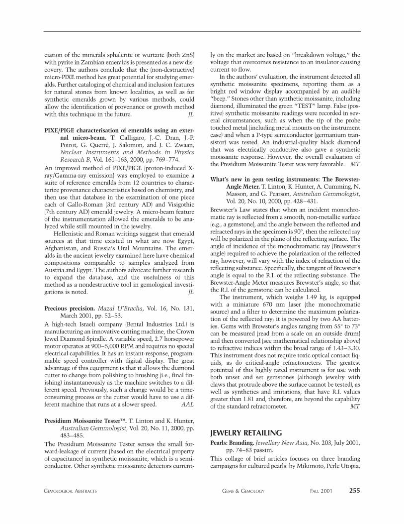
ciation of the minerals sphalerite or wurtzite (both ZnS)with pyrite in Zambian emeralds is presented as a new dis-covery. The authors conclude that the (non-destructive)micro-PIXE method has great potential for studying emer-alds. Further cataloging of chemical and inclusion featuresfor natural stones from known localities, as well as forsynthetic emeralds grown by various methods, couldallow the identification of provenance or growth methodwith this technique in the future. JL
PIXE/PIGE characterisation of emeralds using an exter-nal micro-beam. T. Calligaro, J.-C. Dran, J.-P.Poirot, G. Querré, J. Salomon, and J. C. Zwaan,Nuclear Instruments and Methods in PhysicsResearch B, Vol. 161–163, 2000, pp. 769–774.
An improved method of PIXE/PIGE (proton-induced X-ray/Gamma-ray emission) was employed to examine asuite of reference emeralds from 12 countries to charac-terize provenance characteristics based on chemistry, andthen use that database in the examination of one pieceeach of Gallo-Roman (3rd century AD) and Visigothic(7th century AD) emerald jewelry. A micro-beam featureof the instrumentation allowed the emeralds to be ana-lyzed while still mounted in the jewelry.
Hellenistic and Roman writings suggest that emeraldsources at that time existed in what are now Egypt,Afghanistan, and Russia’s Ural Mountains. The emer-alds in the ancient jewelry examined here have chemicalcompositions comparable to samples analyzed fromAustria and Egypt. The authors advocate further researchto expand the database, and the usefulness of thismethod as a nondestructive tool in gemological investi-gations is noted. JL
Precious precision. Mazal U’Bracha, Vol. 16, No. 131,March 2001, pp. 52–53.
A high-tech Israeli company (Bental Industries Ltd.) ismanufacturing an innovative cutting machine, the CrownJewel Diamond Spindle. A variable speed, 2.7 horsepowermotor operates at 900–5,000 RPM and requires no specialelectrical capabilities. It has an instant-response, program-mable speed controller with digital display. The greatadvantage of this equipment is that it allows the diamondcutter to change from polishing to brushing (i.e., final fin-ishing) instantaneously as the machine switches to a dif-ferent speed. Previously, such a change would be a time-consuming process or the cutter would have to use a dif-ferent machine that runs at a slower speed. AAL
Presidium Moissanite Tester™. T. Linton and K. Hunter,Australian Gemmologist, Vol. 20, No. 11, 2000, pp.483–485.
The Presidium Moissanite Tester senses the small for-ward-leakage of current (based on the electrical propertyof capacitance) in synthetic moissanite, which is a semi-conductor. Other synthetic moissanite detectors current-
ly on the market are based on “breakdown voltage,” thevoltage that overcomes resistance to an insulator causingcurrent to flow.
In the authors’ evaluation, the instrument detected allsynthetic moissanite specimens, reporting them as abright red window display accompanied by an audible“beep.” Stones other than synthetic moissanite, includingdiamond, illuminated the green “TEST” lamp. False (pos-itive) synthetic moissanite readings were recorded in sev-eral circumstances, such as when the tip of the probetouched metal (including metal mounts on the instrumentcase) and when a P-type semiconductor (germanium tran-sistor) was tested. An industrial-quality black diamondthat was electrically conductive also gave a syntheticmoissanite response. However, the overall evaluation ofthe Presidium Moissanite Tester was very favorable. MT
What’s new in gem testing instruments: The Brewster-Angle Meter. T. Linton, K. Hunter, A. Cumming, N.Masson, and G. Pearson, Australian Gemmologist,Vol. 20, No. 10, 2000, pp. 428–431.
Brewster’s Law states that when an incident monochro-matic ray is reflected from a smooth, non-metallic surface(e.g., a gemstone), and the angle between the reflected andrefracted rays in the specimen is 90°, then the reflected raywill be polarized in the plane of the reflecting surface. Theangle of incidence of the monochromatic ray (Brewster’sangle) required to achieve the polarization of the reflectedray, however, will vary with the index of refraction of thereflecting substance. Specifically, the tangent of Brewster’sangle is equal to the R.I. of the reflecting substance. TheBrewster-Angle Meter measures Brewster’s angle, so thatthe R.I. of the gemstone can be calculated.
The instrument, which weighs 1.49 kg, is equippedwith a miniature 670 nm laser (the monochromaticsource) and a filter to determine the maximum polariza-tion of the reflected ray; it is powered by two AA batter-ies. Gems with Brewster’s angles ranging from 55° to 73°can be measured (read from a scale on an outside drum)and then converted (see mathematical relationship above)to refractive indices within the broad range of 1.43–3.30.This instrument does not require toxic optical contact liq-uids, as do critical-angle refractometers. The greatestpotential of this highly rated instrument is for use withboth unset and set gemstones (although jewelry withclaws that protrude above the surface cannot be tested), aswell as synthetics and imitations, that have R.I. valuesgreater than 1.81 and, therefore, are beyond the capabilityof the standard refractometer. MT
JEWELRY RETAILINGPearls: Branding. Jewellery New Asia, No. 203, July 2001,
pp. 74–83 passim.This collage of brief articles focuses on three brandingcampaigns for cultured pearls: by Mikimoto, Perle Utopia,
GEMOLOGICAL ABSTRACTS GEMS & GEMOLOGY FALL 2001 255
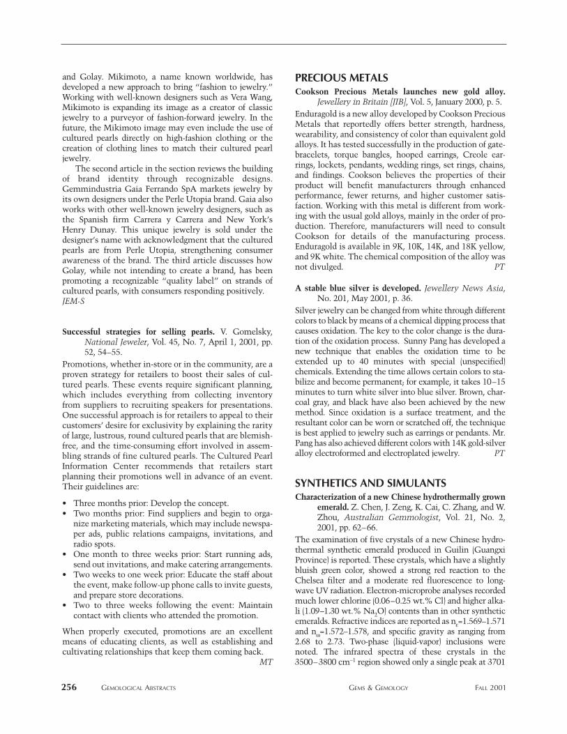
and Golay. Mikimoto, a name known worldwide, hasdeveloped a new approach to bring “fashion to jewelry.”Working with well-known designers such as Vera Wang,Mikimoto is expanding its image as a creator of classicjewelry to a purveyor of fashion-forward jewelry. In thefuture, the Mikimoto image may even include the use ofcultured pearls directly on high-fashion clothing or thecreation of clothing lines to match their cultured pearljewelry.
The second article in the section reviews the buildingof brand identity through recognizable designs.Gemmindustria Gaia Ferrando SpA markets jewelry byits own designers under the Perle Utopia brand. Gaia alsoworks with other well-known jewelry designers, such asthe Spanish firm Carrera y Carrera and New York’sHenry Dunay. This unique jewelry is sold under thedesigner’s name with acknowledgment that the culturedpearls are from Perle Utopia, strengthening consumerawareness of the brand. The third article discusses howGolay, while not intending to create a brand, has beenpromoting a recognizable “quality label” on strands ofcultured pearls, with consumers responding positively.JEM-S
Successful strategies for selling pearls. V. Gomelsky,National Jeweler, Vol. 45, No. 7, April 1, 2001, pp.52, 54–55.
Promotions, whether in-store or in the community, are aproven strategy for retailers to boost their sales of cul-tured pearls. These events require significant planning,which includes everything from collecting inventoryfrom suppliers to recruiting speakers for presentations.One successful approach is for retailers to appeal to theircustomers’ desire for exclusivity by explaining the rarityof large, lustrous, round cultured pearls that are blemish-free, and the time-consuming effort involved in assem-bling strands of fine cultured pearls. The Cultured PearlInformation Center recommends that retailers startplanning their promotions well in advance of an event.Their guidelines are:
• Three months prior: Develop the concept.• Two months prior: Find suppliers and begin to orga-
nize marketing materials, which may include newspa-per ads, public relations campaigns, invitations, andradio spots.
• One month to three weeks prior: Start running ads,send out invitations, and make catering arrangements.
• Two weeks to one week prior: Educate the staff aboutthe event, make follow-up phone calls to invite guests,and prepare store decorations.
• Two to three weeks following the event: Maintaincontact with clients who attended the promotion.
When properly executed, promotions are an excellentmeans of educating clients, as well as establishing andcultivating relationships that keep them coming back.
MT
PRECIOUS METALSCookson Precious Metals launches new gold alloy.
Jewellery in Britain [JIB], Vol. 5, January 2000, p. 5.Enduragold is a new alloy developed by Cookson PreciousMetals that reportedly offers better strength, hardness,wearability, and consistency of color than equivalent goldalloys. It has tested successfully in the production of gate-bracelets, torque bangles, hooped earrings, Creole ear-rings, lockets, pendants, wedding rings, set rings, chains,and findings. Cookson believes the properties of theirproduct will benefit manufacturers through enhancedperformance, fewer returns, and higher customer satis-faction. Working with this metal is different from work-ing with the usual gold alloys, mainly in the order of pro-duction. Therefore, manufacturers will need to consultCookson for details of the manufacturing process.Enduragold is available in 9K, 10K, 14K, and 18K yellow,and 9K white. The chemical composition of the alloy wasnot divulged. PT
A stable blue silver is developed. Jewellery News Asia,No. 201, May 2001, p. 36.
Silver jewelry can be changed from white through differentcolors to black by means of a chemical dipping process thatcauses oxidation. The key to the color change is the dura-tion of the oxidation process. Sunny Pang has developed anew technique that enables the oxidation time to beextended up to 40 minutes with special (unspecified)chemicals. Extending the time allows certain colors to sta-bilize and become permanent; for example, it takes 10–15minutes to turn white silver into blue silver. Brown, char-coal gray, and black have also been achieved by the newmethod. Since oxidation is a surface treatment, and theresultant color can be worn or scratched off, the techniqueis best applied to jewelry such as earrings or pendants. Mr.Pang has also achieved different colors with 14K gold-silveralloy electroformed and electroplated jewelry. PT
SYNTHETICS AND SIMULANTSCharacterization of a new Chinese hydrothermally grown
emerald. Z. Chen, J. Zeng, K. Cai, C. Zhang, and W.Zhou, Australian Gemmologist, Vol. 21, No. 2,2001, pp. 62–66.
The examination of five crystals of a new Chinese hydro-thermal synthetic emerald produced in Guilin (GuangxiProvince) is reported. These crystals, which have a slightlybluish green color, showed a strong red reaction to theChelsea filter and a moderate red fluorescence to long-wave UV radiation. Electron-microprobe analyses recordedmuch lower chlorine (0.06–0.25 wt.% Cl) and higher alka-li (1.09–1.30 wt.% Na2O) contents than in other syntheticemeralds. Refractive indices are reported as ne=1.569–1.571and nw=1.572–1.578, and specific gravity as ranging from2.68 to 2.73. Two-phase (liquid-vapor) inclusions werenoted. The infrared spectra of these crystals in the3500–3800 cm-1 region showed only a single peak at 3701
256 GEMOLOGICAL ABSTRACTS GEMS & GEMOLOGY FALL 2001
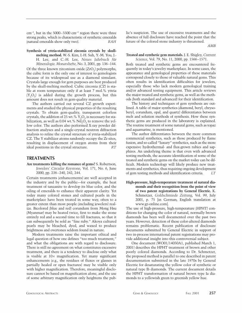
cm-1, but in the 5000–5500 cm-1 region there were threestrong peaks, which is characteristic of synthetic emeralds(natural emeralds show only two). RAH
Synthesis of yttria-stabilized zirconia crystals by skull-melting method. W.-S. Kim, I.-H. Suh, Y.-M. You, J.-H. Lee, and C.-H. Lee, Neues Jahrbuch fürMineralogie, Monatshefte, No. 3, 2001, pp. 136–144.
Of the three known zirconium oxide (ZrO2) polymorphs,the cubic form is the only one of interest to gemologistsbecause of its widespread use as a diamond simulant.Crystals large enough for gem purposes are best producedby the skull-melting method. Cubic zirconia (CZ) is sta-ble at room temperature only if at least 7 mol.% yttria(Y2O3) is added during the growth process, but thisamount does not result in gem-quality material.
The authors carried out several CZ growth experi-ments and studied the physical properties of the resultingcrystals. To obtain gem-quality, transparent colorlesscrystals, the addition of 25 wt.% Y2O3 is necessary for sta-bilization, as well as 0.04 wt.% Nd2O3 to remove the yel-low color. The authors also performed X-ray powder dif-fraction analyses and a single-crystal neutron diffractionanalysis to refine the crystal structure of yttria-stabilizedCZ. The Y stabilizer atoms randomly occupy the Zr sites,resulting in displacement of oxygen atoms from theirideal positions in the crystal structure. RT
TREATMENTSAre treatments killing the romance of gems? S. Robertson,
Jewelers’ Circular Keystone, Vol. 171, No. 6, June2000, pp. 238–240, 242, 244.
Certain treatments (enhancements) are well accepted inthe industry and by the public—for example, the heattreatment of tanzanite to develop its blue color, and theoiling of emeralds to enhance their apparent clarity. Yettoday many colored stones and cultured pearls in themarketplace have been treated in some way, often to agreater extent than most people (including jewelers) real-ize. Bicolored (blue and red) corundum from Mong Hsu(Myanmar) may be heated twice, first to make the stoneentirely red and a second time to fill fractures, so that itcan subsequently be sold as “fine ruby.” Akoya culturedpearls may be bleached, dyed, and waxed to producebrightness and overtones seldom found in nature.
Modern treatments raise the important ethical andlegal question of how one defines “too much treatment,”and what the obligations are with regard to disclosure.There is still no agreement on what constitutes excessivetreatment, and there is a tendency to disclose only whatis visible at 10¥ magnification. Yet many significantenhancements (e.g., the residues of fluxes or glasses inpartially healed or open fractures) may be visible onlywith higher magnification. Therefore, meaningful disclo-sure cannot be based on magnification alone, and the useof some arbitrary magnification only heightens the pub-
lic’s suspicion. The use of excessive treatments and theabsence of full disclosure have reached the point that thefuture of the colored stone industry is threatened.
AMB
Treated and synthetic gem materials. J. E. Shigley, CurrentScience, Vol. 79, No. 11, 2000, pp. 1566–1571.
Both treated and synthetic gems are encountered fre-quently in today’s jewelry marketplace. In some cases, theappearance and gemological properties of these materialscorrespond closely to those of valuable natural gems. Thisoften results in identification difficulties for jewelers,especially those who lack modern gemological trainingand/or advanced testing equipment. This article reviewsthe major treated and synthetic gems, as well as the meth-ods (both standard and advanced) for their identification.
The history and techniques of gem synthesis are out-lined. A table of major synthetics (diamond, beryl, chryso-beryl, corundum, opal, and quartz) differentiates betweenmelt and solution methods of synthesis. How these syn-thetic gems are produced in the laboratory is explained.The routine treatment of some natural gems, such as topazand aquamarine, is mentioned.
The author differentiates between the more commoncommercial synthetics, such as those produced by flamefusion, and so-called “luxury” synthetics, such as the moreexpensive hydrothermal- and flux-grown rubies and sap-phires. An underlying theme is that even with advancedtesting methods, the accurate identification of some of thetreated and synthetic gems on the market today can be dif-ficult. Modern technology will likely produce new treat-ments and synthetics, thus requiring ongoing developmentof gem testing methods and identification criteria. LT
High-pressure, high-temperature treatment of natural dia-monds and their recognition from the point of viewof two patent registrations by General Electric. K.Schmetzer, Goldschmiede Zeitung, Vol. 99, July2001, p. 75 [in German; English translation atwww.gz-online.com].
The use of high-pressure, high-temperature (HPHT) con-ditions for changing the color of natural, normally browndiamonds has been well documented over the past twoyears. However, detection of these color-altered diamondsremains problematic. Recent publication of disclosuredocuments submitted by General Electric in support oftwo in-process international patent registrations may pro-vide additional insight into this controversial subject.
One document (WO01/14050A1, published March 1,2001) describes the HPHT treatment of brown and otherpoorly colored diamonds. According to Dr. Schmetzer,the proposed method is parallel to one described in patentdocumentation submitted in the late 1970s by GeneralElectric for desaturating the yellow color of synthetic ornatural type Ib diamonds. The current document detailsthe HPHT transformation of natural brown type Ia dia-monds to a yellowish green to greenish yellow hue.
GEMOLOGICAL ABSTRACTS GEMS & GEMOLOGY FALL 2001 257

A second document (WO01/33203A1, published May10, 2001) illustrates a method for detecting HPHT-treateddiamonds based on photoluminescence criteria. The fun-damental premise: Absence of the 490.7 nm photolumi-nescence line—generally present in natural type I andtype II diamonds—indicates a 95% probability of HPHTtreatment. While other articles cited by Dr. Schmetzerindicate a similar approach to HPHT detection, he alsorefers to at least one study that raises some questionsabout the reliability of the 95% accuracy claim in thispatent document. SW
MISCELLANEOUSAmerican Watch Guild makes time for excellence. W. G.
Shuster, Jewelers’ Circular Keystone, Vol. 171, No.11, November 2000, pp. 176 –177.
Using the American Gem Society and its ethical princi-ples as a model, a group of authorized retailers of finewatches have banded together to form a modern-dayguild. The new American Watch Guild (AWG, headquar-tered in Hewlett, New York) will bring together autho-rized retailers, service providers, and manufacturers oftimepieces who are committed to excellence in both salesand service. Members can be identified by means of AWGdecals and plaques. The guild is making itself knownthrough exhibitions of fine timepieces, charitable activi-ties, and a scholarship fund.
The need for such a guild stems from marketing prac-tices that are unacceptable to ethical, professionallytrained jewelers. Such practices include: gray marketing(sales by unauthorized dealers), transshipping (sales byauthorized dealers to unauthorized vendors), counterfeit-ing, and the proliferation of Internet vendors who sellgenuine timepieces without authorization. AAL
America’s largest parking lot. C. Wolinsky, NationalGeographic, Vol. 199, No. 1, January 2001, pp.124–128.
The population of Quartzsite, Arizona swells from 2,300year-round residents to more than a million at its winterpeak in January. Although this article concentrates on theflea-market atmosphere of mid-winter Quartzsite, gemand mineral people know it as the show that precedesTucson, and unusual lapidary material is likely to appearthere first. Just don’t expect many amenities—Quartzsiteis mostly a dry-camping location, with many visitorsstaying in recreational vehicles. Mary L. Johnson
The De Beers story: A new cut on an old monopoly. N.Stein, Fortune, Vol. 143, No. 4, February 19, 2001,pp. 186–206 passim.
This article reviews the recent history of De Beers andexamines its future in the 21st century diamond marketbased on an inside view of the company and visits to min-ing operations in southern Africa. Early on the authorexpresses his concern about the motives for the company’s
recent business moves and poses the question: Why woulda company voluntarily give up control of the world dia-mond supply after 100 years, move to a new open worldmarket of diamonds, and develop a “Supplier of Choice”strategy?
It becomes clear that De Beers had little choice but torethink the way it was doing business to thrive in thefuture. During the 1990s, De Beers saw its market share ofworld rough diamond sales fall from 85% to 65% and itsstockpile of rough diamonds increase to US$5 billion. Thiswas due to three major factors: the collapse of the SovietUnion in 1991, Argyle’s termination of its contract withDe Beers in 1996, and the rise of new diamond producers—especially Canada. All these entities sell at least a majorportion of their diamonds outside the cartel. Further, theinvestment community voiced its concern as De Beers’sstock plummeted to $12/share in the late 1990s. Hence, anew strategy was necessary that would work in a signifi-cantly more competitive market.
A cornerstone of the new De Beers is the developmentof brand names such as “Forevermark” to stimulate con-sumer demand. The new plan creates the “Supplier ofChoice” category of sightholder who is able to build strongbrands independently or by teaming up with other compa-nies. Hence, the new breed of sightholders will be fewer innumber than in the past, but they will be the financiallystrongest manufacturer with the best retail marketingskills. “The cartel of many will be transformed into anequally powerful cartel of the few.” The article reminds thereader that for this plan to succeed, De Beers must allay thefears of antitrust regulators in the U.S. and abroad. PY
Tahiti sets up pearl ministry. Jewellery News Asia, No.200, April 2001, pp. 1, 44.
The French Polynesian government has created a min-istry devoted entirely to cultured pearls. Initial goals ofthis ministry will be to:
1. Revise the existing industry classification chart sothat the rejects category will be expanded.
2. Set up a standard for nacre thickness to prevent imma-ture or thinly coated cultured pearls from reaching themarket.
3. Ensure that customs controls will prevent inferior-quality cultured pearls from leaving the country.
These measures, aimed at boosting wholesale prices andconsumer confidence, were announced amid the negativepublicity generated by the influx of low-quality Tahitiancultured pearls in the world market. The creation of theministry has been well received by Tahiti’s pearl cultur-ing industry. In fact, the industry had been requestinggovernment intervention to help secure the long-termfuture of pearl farming in the area. The President ofFrench Polynesia, Gaston Flosse, will serve as the head ofthe new ministry. JEM-S
258 GEMOLOGICAL ABSTRACTS GEMS & GEMOLOGY FALL 2001