rodgers 321 upgrade to vtpo frank evans [email protected]
TRANSCRIPT

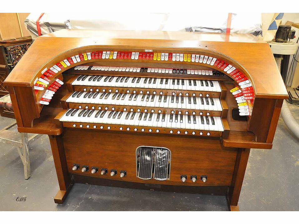
After having extensively modified my Rodgers 340, I used the MIDI out capability to “play around” with the concept of a virtual theater pipe organ or VTPO as it is called in the hobby. Starting out with a fine program called Miditzer and the progressing to GigaStudio 3 and samples provided by Joe Hardy it became apparent that this technology could be as expensive or inexpensive as one wanted. Soon after I purchased Hauptwerk as the digital sound engine and several “organs” or actually sets of samples that have been assembled into a group to be used as an organ. The current one that I am using is the Paramount 3 manual 32 rank or 3/32. The problem was that to set up the VTPO required re-programming the system and connecting the amps to the computer, setting the levels and positioning the speakers them, to play the Rodgers as an analog organ all that had to be undone and set back up. Total time was about an hour or more. I began thinking about either gutting the 340 and making the conversion total, complete and un-reversible or another console. Since the resident (in the shop) Robert Morton 3 manual console was/is bound for another project, that was out. Besides my bride said it was ugly………In September of 2012 I purchased a Rodgers 321 off of eBay. It had led a rough life but was complete with both speaker cabinets, price was right and it was only about 250 miles away. That was an easy trip to pick it up. We did manage to pick a day that allowed for major rain from the time it was picked up until we arrived back in Meridian, MS. We did take tarps and wrapped up all and had no problems.
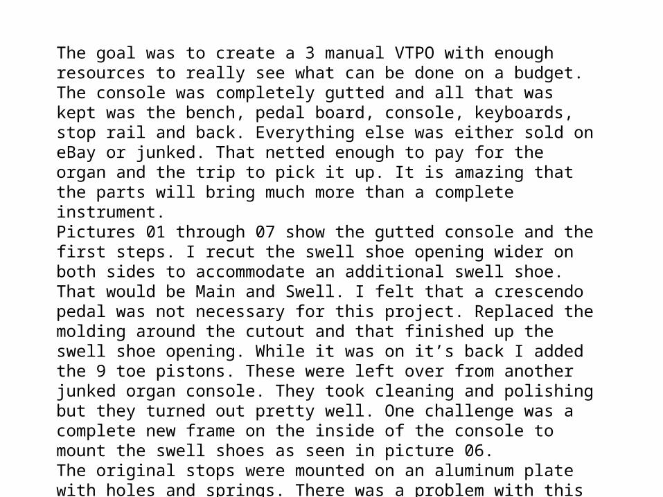
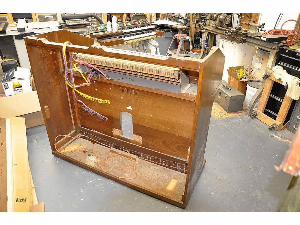
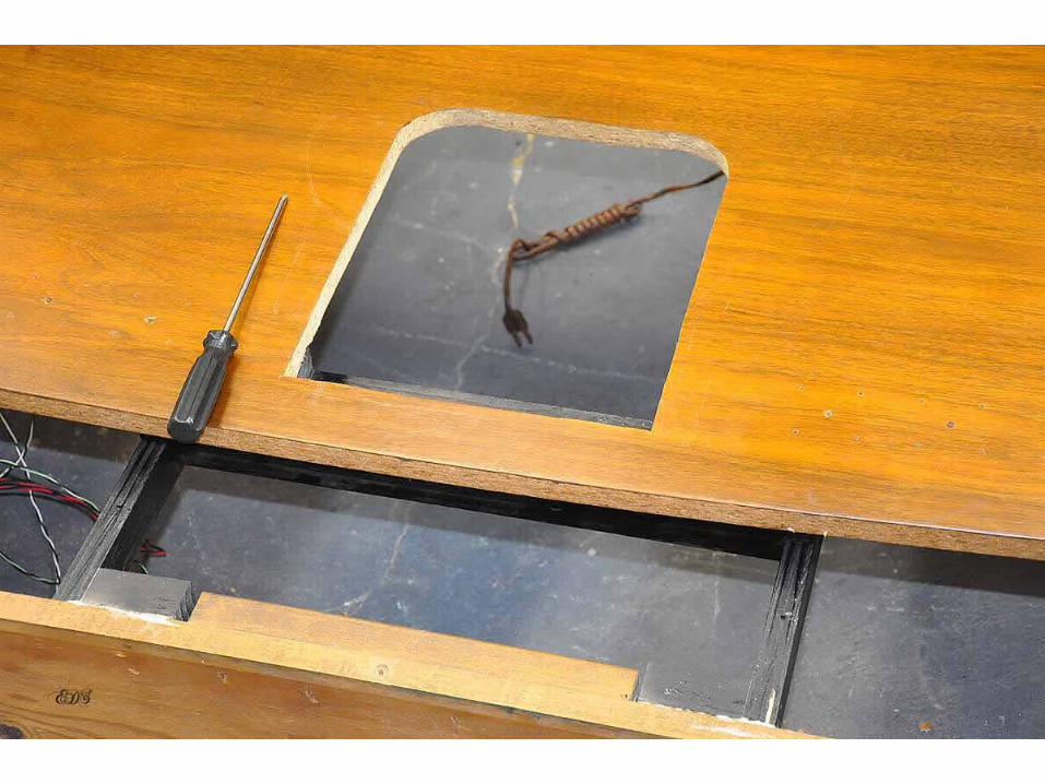
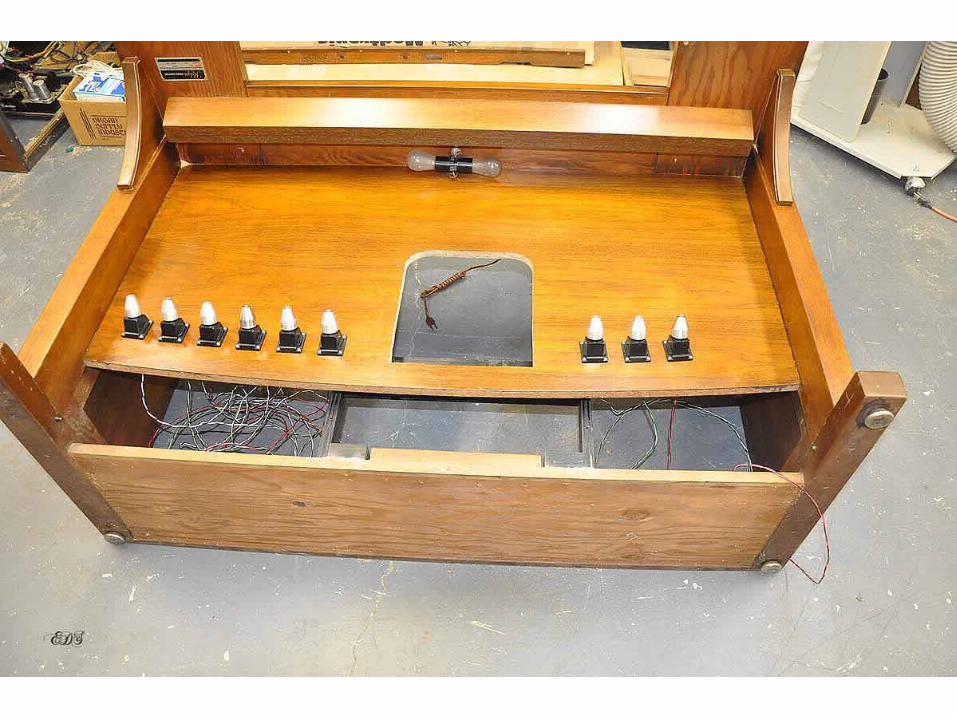
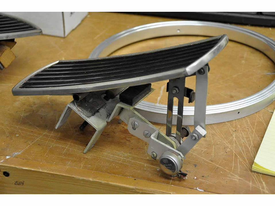
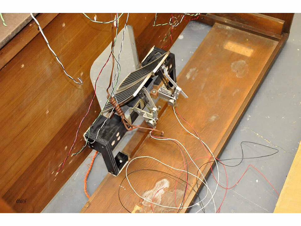
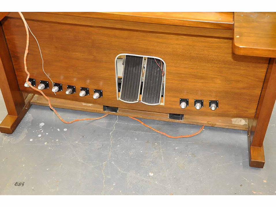
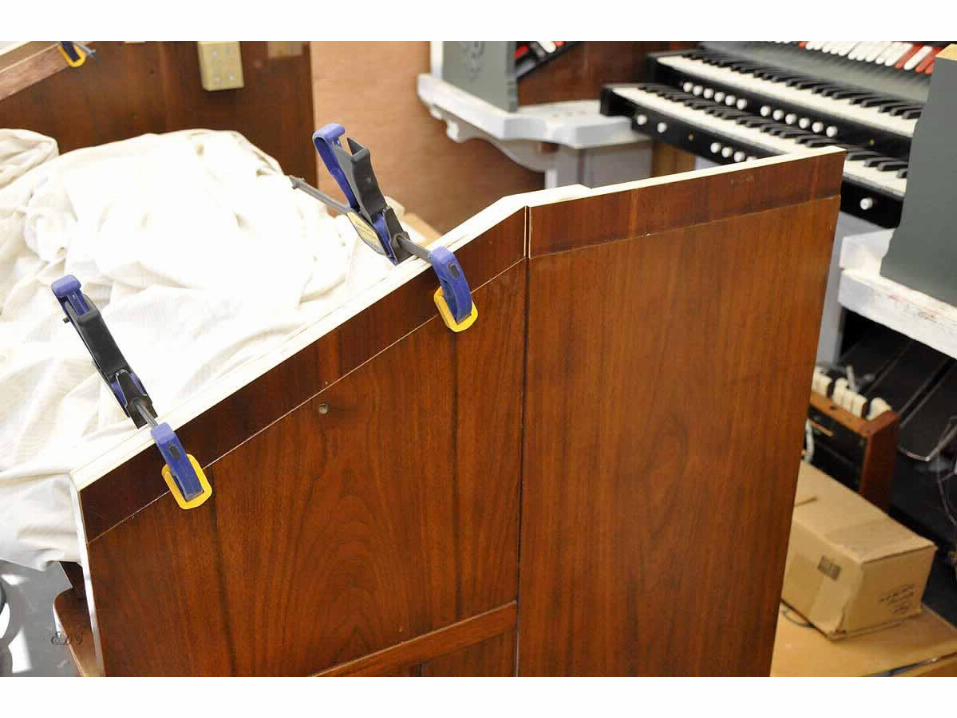
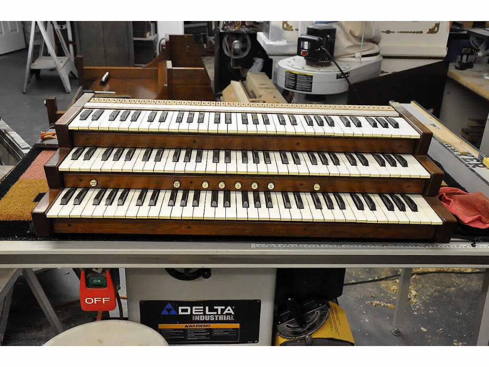
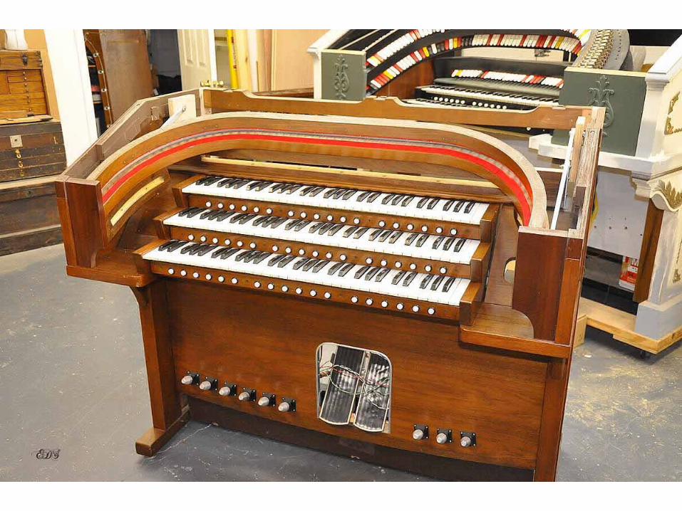
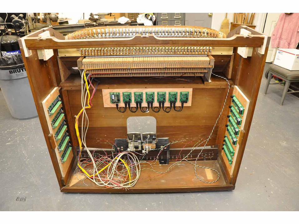
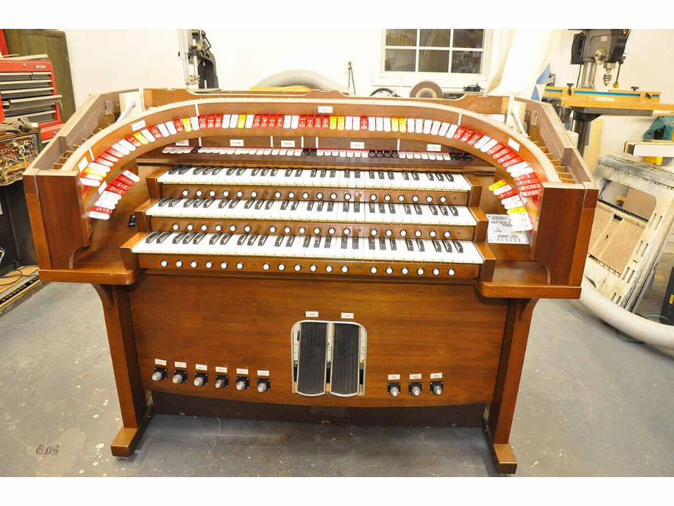
The goal was to create a 3 manual VTPO with enough resources to really see what can be done on a budget. The console was completely gutted and all that was kept was the bench, pedal board, console, keyboards, stop rail and back. Everything else was either sold on eBay or junked. That netted enough to pay for the organ and the trip to pick it up. It is amazing that the parts will bring much more than a complete instrument.Pictures 01 through 07 show the gutted console and the first steps. I recut the swell shoe opening wider on both sides to accommodate an additional swell shoe. That would be Main and Swell. I felt that a crescendo pedal was not necessary for this project. Replaced the molding around the cutout and that finished up the swell shoe opening. While it was on it’s back I added the 9 toe pistons. These were left over from another junked organ console. They took cleaning and polishing but they turned out pretty well. One challenge was a complete new frame on the inside of the console to mount the swell shoes as seen in picture 06.The original stops were mounted on an aluminum plate with holes and springs. There was a problem with this since I planned on using SAMs for the stop actions. First the upper and lower rails were too thick and would cause the tabs to be recessed 3/8 of an inch too far, second the spacing of the holes in the aluminum frame spaced the tabs too far apart.
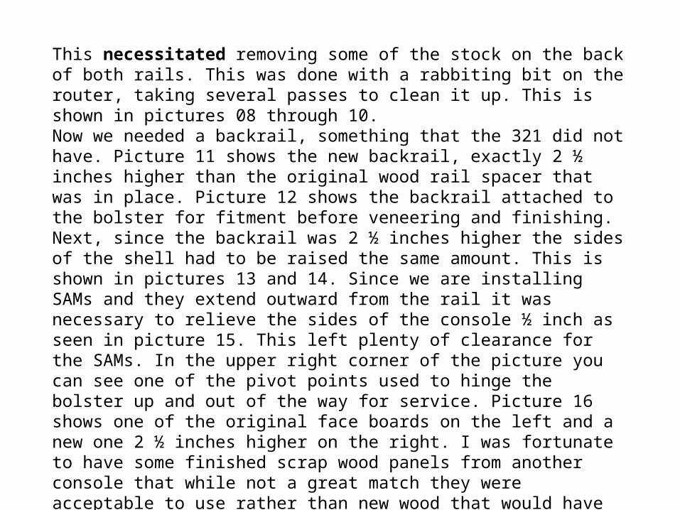
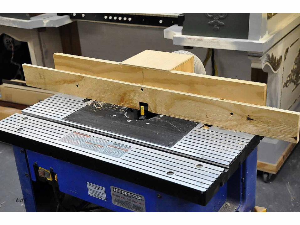
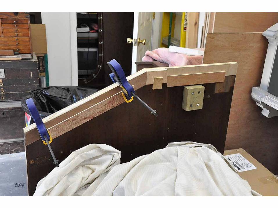
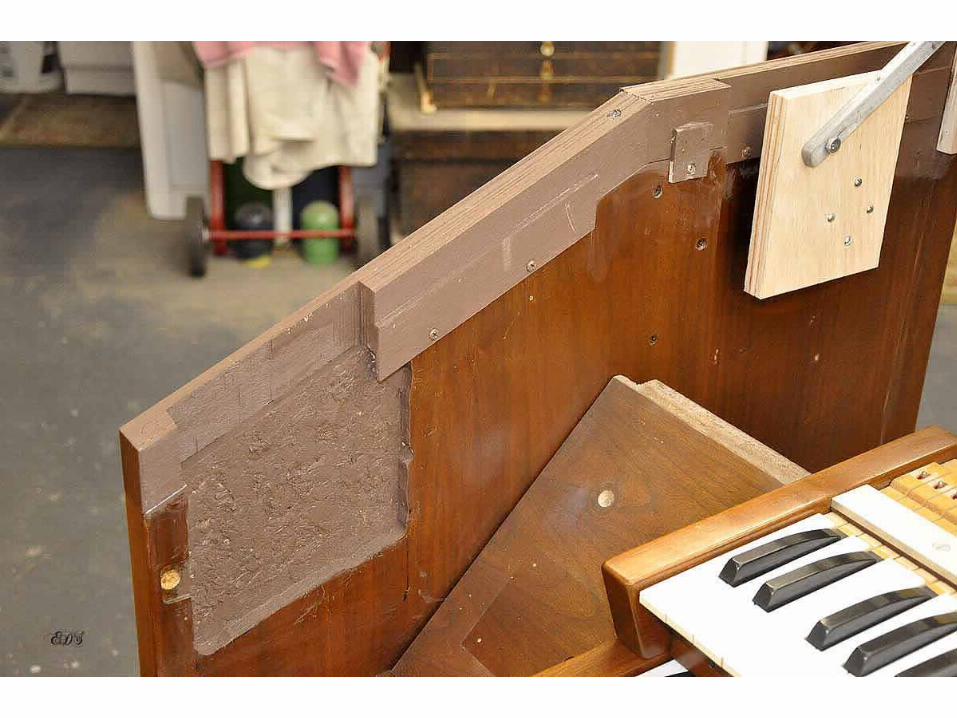
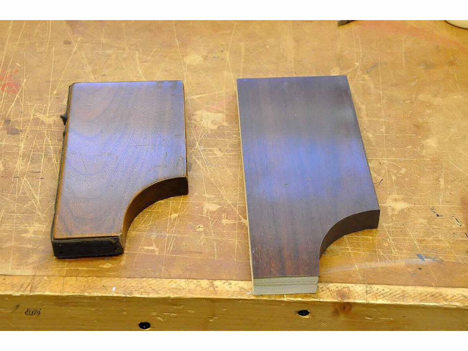
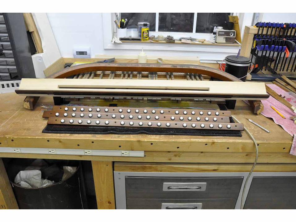
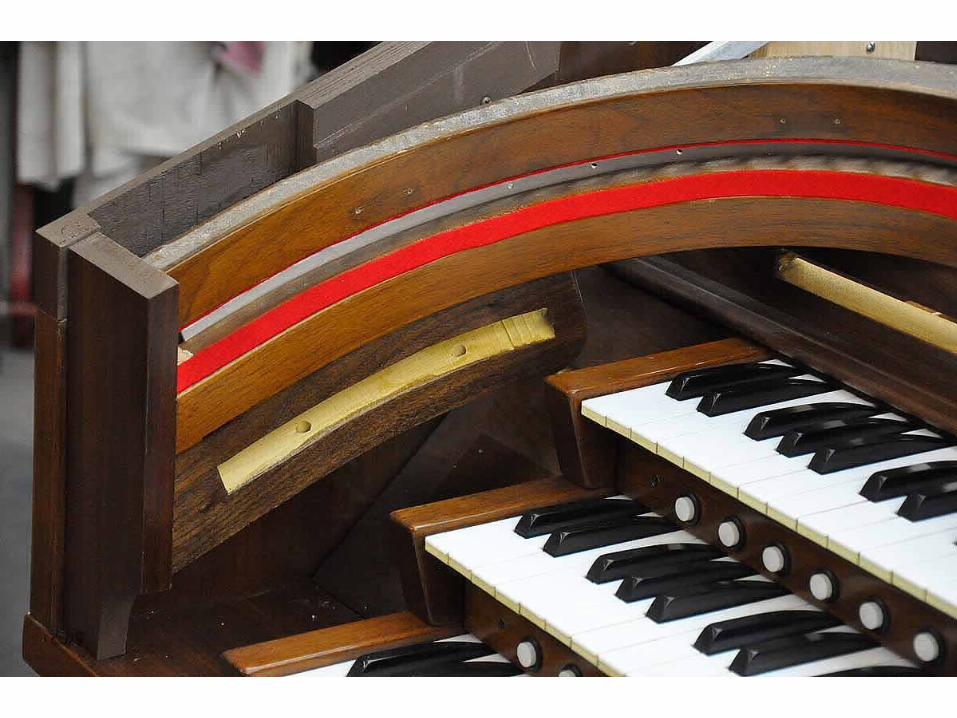
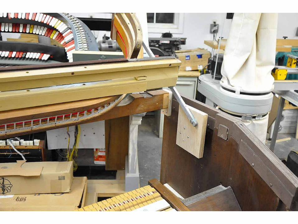
This necessitated removing some of the stock on the back of both rails. This was done with a rabbiting bit on the router, taking several passes to clean it up. This is shown in pictures 08 through 10.Now we needed a backrail, something that the 321 did not have. Picture 11 shows the new backrail, exactly 2 ½ inches higher than the original wood rail spacer that was in place. Picture 12 shows the backrail attached to the bolster for fitment before veneering and finishing.Next, since the backrail was 2 ½ inches higher the sides of the shell had to be raised the same amount. This is shown in pictures 13 and 14. Since we are installing SAMs and they extend outward from the rail it was necessary to relieve the sides of the console ½ inch as seen in picture 15. This left plenty of clearance for the SAMs. In the upper right corner of the picture you can see one of the pivot points used to hinge the bolster up and out of the way for service. Picture 16 shows one of the original face boards on the left and a new one 2 ½ inches higher on the right. I was fortunate to have some finished scrap wood panels from another console that while not a great match they were acceptable to use rather than new wood that would have to be finished.The keyboards were next. Pictures 17, 18 and 19 show this. They were cleaned, adjusted and then 18 pistons mounted in each of the 3 key slips. The current price of true thumb pistons is pretty steep and since most organists don’t actually look at them when they press them I felt that another method was in order.
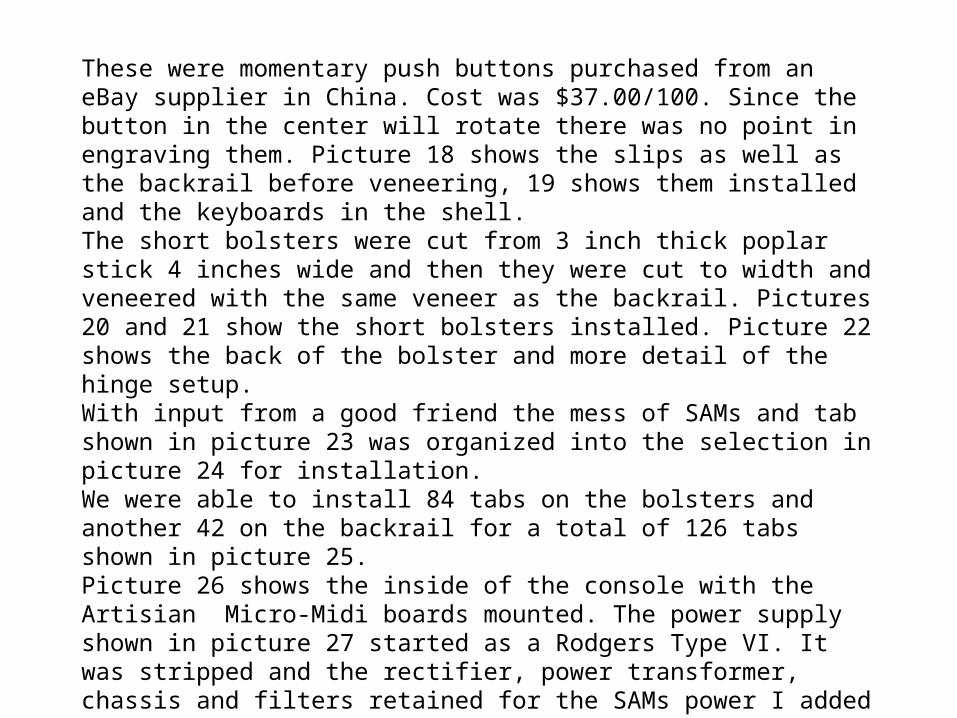
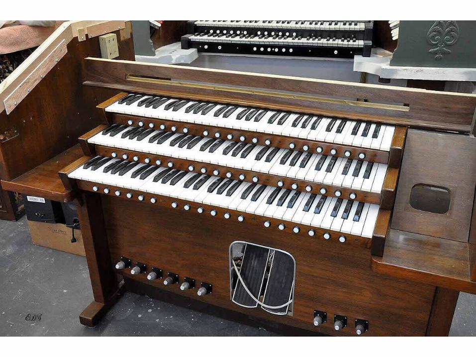
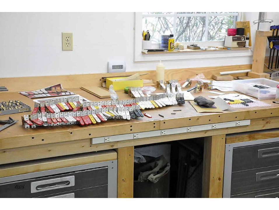
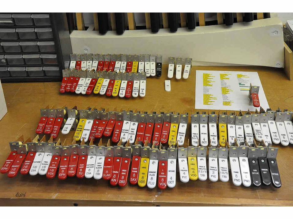
These were momentary push buttons purchased from an eBay supplier in China. Cost was $37.00/100. Since the button in the center will rotate there was no point in engraving them. Picture 18 shows the slips as well as the backrail before veneering, 19 shows them installed and the keyboards in the shell.The short bolsters were cut from 3 inch thick poplar stick 4 inches wide and then they were cut to width and veneered with the same veneer as the backrail. Pictures 20 and 21 show the short bolsters installed. Picture 22 shows the back of the bolster and more detail of the hinge setup.With input from a good friend the mess of SAMs and tab shown in picture 23 was organized into the selection in picture 24 for installation.We were able to install 84 tabs on the bolsters and another 42 on the backrail for a total of 126 tabs shown in picture 25.Picture 26 shows the inside of the console with the Artisian Micro-Midi boards mounted. The power supply shown in picture 27 started as a Rodgers Type VI. It was stripped and the rectifier, power transformer, chassis and filters retained for the SAMs power I added a piece of aluminum where the printed circuit board had been and upon that built the +5 volt logic supply and the 16 volt AC supply for the console lights.Picture 28 shows the console with the various tags installed as well as the division separators. We decided to use 3/16 inch wide white bars to show the division between the sections of the tabs rather than waste a tab position with a 7/8 inch wide block of wood. Now it is time to wire the critter.