rockwell io 1756 controllogix-io tech data en 0611
DESCRIPTION
plcTRANSCRIPT
Technical Data
1756 ControlLogix I/O Modules Specifications
Catalog Numbers 1756 series
The ControlLogix architecture provides a wide range of input and output modules to span many applications, from high-speed digital to process control. The ControlLogix architecture uses Producer-Consumer technology, which allows input information and output status to be shared among multiple ControlLogix controllers.
Each ControlLogix I/O module mounts in a ControlLogix chassis and requires either a removable terminal block (RTB) or a 1492 interface module (IFM) to connect all field-side wiring. RTBs and IFMs are not included with the I/O modules. They must be ordered separately.
Topic Page
Available 1756 I/O Modules 3
Digital I/O Modules 3
Analog I/O Modules 5
Specialty I/O Modules 5
Module Specifications 6
ControlLogix I/O Accessories 184
www.klinkmann.com6 / 2011
1756 ControlLogix I/O Modules Specifications www.klinkmann.com6 / 2011
Important User Information
Solid state equipment has operational characteristics differing from those of electromechanical equipment. Safety Guidelines for the Application, Installation and Maintenance of Solid State Controls (publication SGI-1.1 available from your local Rockwell Automation sales office or online at http://www.rockwellautomation.com/literature/) describes some important differences between solid state equipment and hard-wired electromechanical devices. Because of this difference, and also because of the wide variety of uses for solid state equipment, all persons responsible for applying this equipment must satisfy themselves that each intended application of this equipment is acceptable.
In no event will Rockwell Automation, Inc. be responsible or liable for indirect or consequential damages resulting from the use or application of this equipment.
The examples and diagrams in this manual are included solely for illustrative purposes. Because of the many variables and requirements associated with any particular installation, Rockwell Automation, Inc. cannot assume responsibility or liability for actual use based on the examples and diagrams.
No patent liability is assumed by Rockwell Automation, Inc. with respect to use of information, circuits, equipment, or software described in this manual.
Reproduction of the contents of this manual, in whole or in part, without written permission of Rockwell Automation, Inc., is prohibited.
Throughout this manual, when necessary, we use notes to make you aware of safety considerations.
Rockwell Automation, Rockwell Software, Allen-Bradley, TechConnect, ControlLogix, GuardLogix, and RSLogix 5000 are trademarks of Rockwell Automation, Inc.
Trademarks not belonging to Rockwell Automation are property of their respective companies.
WARNING: Identifies information about practices or circumstances that can cause an explosion in a hazardous environment, which may lead to personal injury or death, property damage, or economic loss.
IMPORTANT Identifies information that is critical for successful application and understanding of the product.
ATTENTION: Identifies information about practices or circumstances that can lead to personal injury or death, property damage, or economic loss. Attentions help you identify a hazard, avoid a hazard, and recognize the consequence
SHOCK HAZARD: Labels may be on or inside the equipment, for example, a drive or motor, to alert people that dangerous voltage may be present.
BURN HAZARD: Labels may be on or inside the equipment, for example, a drive or motor, to alert people that surfaces may reach dangerous temperatures.
2 Rockwell Automation Publication 1756-TD002C-EN-E - September 2010
1756 ControlLogix I/O Modules Specificationswww.klinkmann.com6 / 2011
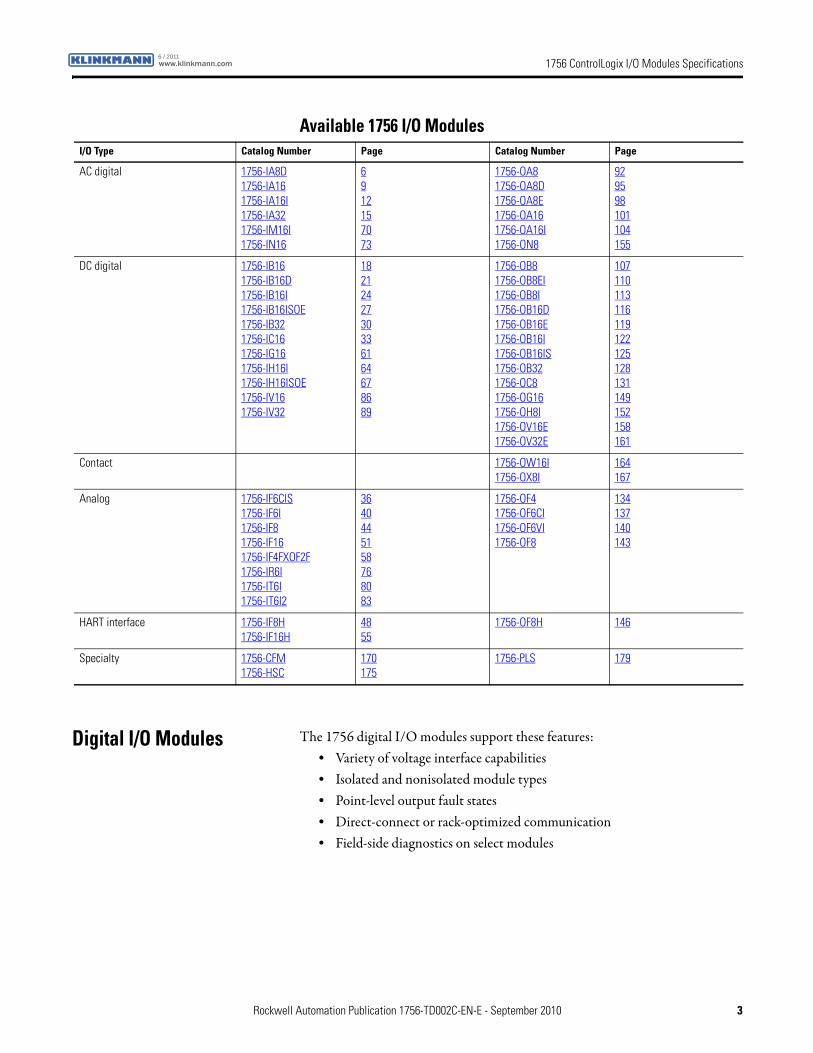
Available 1756 I/O Modules
Digital I/O Modules The 1756 digital I/O modules support these features:• Variety of voltage interface capabilities• Isolated and nonisolated module types• Point-level output fault states• Direct-connect or rack-optimized communication• Field-side diagnostics on select modules
I/O Type Catalog Number Page Catalog Number Page
AC digital 1756-IA8D1756-IA161756-IA16I1756-IA321756-IM16I1756-IN16
6912157073
1756-OA81756-OA8D1756-OA8E1756-OA161756-OA16I1756-ON8
929598101104155
DC digital 1756-IB161756-IB16D1756-IB16I1756-IB16ISOE1756-IB321756-IC161756-IG161756-IH16I1756-IH16ISOE1756-IV161756-IV32
1821242730336164678689
1756-OB81756-OB8EI1756-OB8I1756-OB16D1756-OB16E1756-OB16I1756-OB16IS1756-OB321756-OC81756-OG161756-OH8I1756-OV16E1756-OV32E
107110113116119122125128131149152158161
Contact 1756-OW16I1756-OX8I
164167
Analog 1756-IF6CIS1756-IF6I1756-IF81756-IF161756-IF4FXOF2F1756-IR6I1756-IT6I1756-IT6I2
3640445158768083
1756-OF41756-OF6CI1756-OF6VI1756-OF8
134137140143
HART interface 1756-IF8H1756-IF16H
4855
1756-OF8H 146
Specialty 1756-CFM1756-HSC
170175
1756-PLS 179
Rockwell Automation Publication 1756-TD002C-EN-E - September 2010 3
1756 ControlLogix I/O Modules Specifications www.klinkmann.com6 / 2011
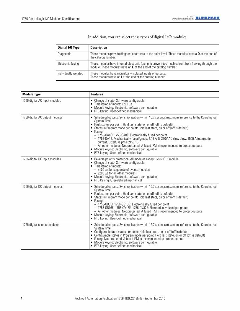
In addition, you can select these types of digital I/O modules.
Digital I/O Type Description
Diagnostic These modules provide diagnostic features to the point level. These modules have a D at the end of the catalog number.
Electronic fusing These modules have internal electronic fusing to prevent too much current from flowing through the module. These modules have an E at the end of the catalog number.
Individually isolated These modules have individually isolated inputs or outputs.These modules have an I at the end of the catalog number.
Module Type Features
1756 digital AC input modules • Change of state: Software configurable• Timestamp of inputs: ±200 μs• Module keying: Electronic, software configurable• RTB keying: User-defined mechanical
1756 digital AC output modules • Scheduled outputs: Synchronization within 16.7 seconds maximum, reference to the Coordinated System Time
• Fault states per point: Hold last state, on or off (off is default)• States in Program mode per point: Hold last state, on or off (off is default)• Fusing:
– 1756-OA8D, 1756-OA8E: Electronically fused per point– 1756-OA16: Mechanically fused/group, 3.15 A @ 250V AC slow blow, 1500 A interruption
current, Littelfuse p/n H2153.15– All other modules: Not protected. A fused IFM is recommended to protect outputs
• Module keying: Electronic, software configurable• RTB keying: User-defined mechanical
1756 digital DC input modules • Reverse polarity protection: All modules except 1756-IG16 module• Change of state: Software configurable• Timestamp of inputs:
– ±100 μs for sequence of events modules– ±200 μs for all other modules
• Module keying: Electronic, software configurable• RTB Keying: User-defined mechanical
1756 digital DC output modules • Scheduled outputs: Synchronization within 16.7 seconds maximum, reference to the Coordinated System Time
• Fault states per point: Hold last state, on or off (off is default)• States in Program mode per point: Hold last state, on or off (off is default)• Fusing:
– 1756-OB8EI, 1756-OB16D: Electronically fused per point– 1756-OB16E, 1756-OV16E, 1756-OV32E: Electronically fused per group– All other modules. Not protected. A fused IFM is recommended to protect outputs
• Module keying: Electronic, software configurable• RTB keying: User-defined mechanical
1756 digital contact modules • Scheduled outputs: Synchronization within 16.7 seconds maximum, reference to the Coordinated System Time
• Configurable fault states per point: Hold last state, on or off (off is default)• Configurable states in Program mode per point: Hold last state, on or off (off is default)• Fusing: Not protected. A fused IFM is recommended to protect outputs• Module keying: Electronic, software configurable• RTB keying: User-defined mechanical
4 Rockwell Automation Publication 1756-TD002C-EN-E - September 2010
1756 ControlLogix I/O Modules Specificationswww.klinkmann.com6 / 2011
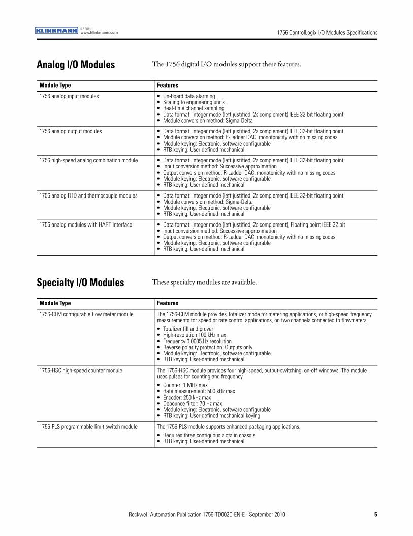
Analog I/O Modules The 1756 digital I/O modules support these features.
Specialty I/O Modules These specialty modules are available.
Module Type Features
1756 analog input modules • On-board data alarming• Scaling to engineering units• Real-time channel sampling• Data format: Integer mode (left justified, 2s complement) IEEE 32-bit floating point• Module conversion method: Sigma-Delta
1756 analog output modules • Data format: Integer mode (left justified, 2s complement) IEEE 32-bit floating point• Module conversion method: R-Ladder DAC, monotonicity with no missing codes• Module keying: Electronic, software configurable• RTB keying: User-defined mechanical
1756 high-speed analog combination module • Data format: Integer mode (left justified, 2s complement) IEEE 32-bit floating point• Input conversion method: Successive approximation• Output conversion method: R-Ladder DAC, monotonicity with no missing codes• Module keying: Electronic, software configurable• RTB keying: User-defined mechanical
1756 analog RTD and thermocouple modules • Data format: Integer mode (left justified, 2s complement) IEEE 32-bit floating point• Module conversion method: Sigma-Delta• Module keying: Electronic, software configurable• RTB keying: User-defined mechanical
1756 analog modules with HART interface • Data format: Integer mode (left justified, 2s complement), Floating point IEEE 32 bit• Input conversion method: Successive approximation• Output conversion method: R-Ladder DAC, monotonicity with no missing codes• Module keying: Electronic, software configurable• RTB keying: User-defined mechanical
Module Type Features
1756-CFM configurable flow meter module The 1756-CFM module provides Totalizer mode for metering applications, or high-speed frequency measurements for speed or rate control applications, on two channels connected to flowmeters.• Totalizer fill and prover• High-resolution 100 kHz max• Frequency 0.0005 Hz resolution• Reverse polarity protection: Outputs only• Module keying: Electronic, software configurable• RTB keying: User-defined mechanical
1756-HSC high-speed counter module The 1756-HSC module provides four high-speed, output-switching, on-off windows. The module uses pulses for counting and frequency.• Counter: 1 MHz max• Rate measurement: 500 kHz max• Encoder: 250 kHz max• Debounce filter: 70 Hz max• Module keying: Electronic, software configurable• RTB keying: User-defined mechanical keying
1756-PLS programmable limit switch module The 1756-PLS module supports enhanced packaging applications.• Requires three contiguous slots in chassis• RTB keying: User-defined mechanical
Rockwell Automation Publication 1756-TD002C-EN-E - September 2010 5
1756 ControlLogix I/O Modules Specifications www.klinkmann.com6 / 2011
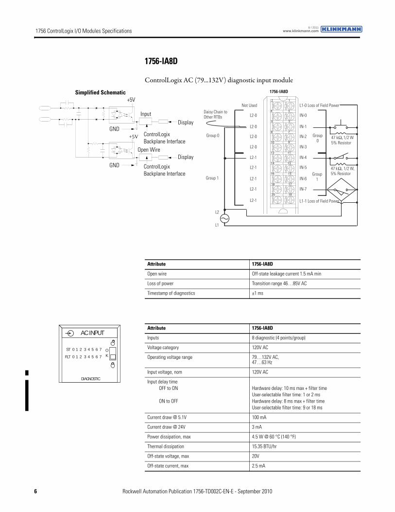
1756-IA8D
ControlLogix AC (79...132V) diagnostic input module
+5V
12
34
56
78
910
1112
1314
1516
1718
1920
47 kΩ, 1/2 W, 5% Resistor
47 kΩ, 1/2 W5% Resistor
Not Used
L2-0
L2-0
L2-0
L2-0
L2-1
L2-1
L2-1
L2-1
L2-1
L1-0 Loss of Field Power
IN-0
IN-1
IN-2
IN-3
IN-4
IN-5
IN-6
IN-7
L1-1 Loss of Field Power
Daisy Chain to Other RTBs
Group 0
Group 0
Group 1Group 1
L2
L1
1756-IA8D
ControlLogix Backplane Interface
ControlLogix Backplane Interface
Display
Simplified Schematic
Input
DisplayOpen Wire
GND
GND
+5V
Attribute 1756-IA8D
Open wire Off-state leakage current 1.5 mA min
Loss of power Transition range 46…85V AC
Timestamp of diagnostics ±1 ms
Attribute 1756-IA8D
Inputs 8 diagnostic (4 points/group)
Voltage category 120V AC
Operating voltage range 79…132V AC,47…63 Hz
Input voltage, nom 120V AC
Input delay timeOFF to ON
ON to OFF
Hardware delay: 10 ms max + filter timeUser-selectable filter time: 1 or 2 msHardware delay: 8 ms max + filter timeUser-selectable filter time: 9 or 18 ms
Current draw @ 5.1V 100 mA
Current draw @ 24V 3 mA
Power dissipation, max 4.5 W @ 60 °C (140 °F)
Thermal dissipation 15.35 BTU/hr
Off-state voltage, max 20V
Off-state current, max 2.5 mA
AC INPUT
ST
FLT
0 1 2 3 4 5 6 7
0 1 2 3 4 5 6 7OK
DIAGNOSTIC
6 Rockwell Automation Publication 1756-TD002C-EN-E - September 2010
1756 ControlLogix I/O Modules Specificationswww.klinkmann.com6 / 2011
On-state current, min 5 mA @ 74V AC
On-state current, max 16 mA @ 132V AC
Inrush current, max 250 mA
Input impedance, max 8.25 kΩ @ 132V AC, 60 Hz
Cyclic update time 200 μs...750 ms
Isolation voltage 125V (continuous), basic insulation type, inputs-to-backplane, and input group-to-groupNo isolation between individual group inputs
Routine tested @ 1200V AC for 2 s
Removable terminal block housing 1756-TBNH1756-TBSH
Slot width 1
Wire size 0.33... 2.1 mm2 (22...14 AWG) solid or stranded copper wire rated at 90 °C (194 °F), or greater, 1.2 mm (3/64 in.) insulation max(1)
Wire category 1(2)
North American temperature code T4A
Enclosure type None (open-style)
(1) Maximum wire size requires extended housing, catalog number 1756-TBE.
(2) Use this conductor category information for planning conductor routing as described in the system-level installation manual. See the Industrial Automation Wiring and Grounding Guidelines, publication 1770-4.1.
Attribute 1756-IA8D
Attribute 1756-IA8D
Temperature, operatingIEC 60068-2-1 (Test Ad, Operating Cold),IEC 60068-2-2 (Test Bd, Operating Dry Heat),IEC 60068-2-14 (Test Nb, Operating Thermal Shock)
0…60 °C (32…140 °F)
Temperature, surrounding air 60 °C (140 °F)
Temperature, storageIEC 60068-2-1 (Test Ab, Unpackaged Nonoperating Cold),IEC 60068-2-2 (Test Bb, Unpackaged Nonoperating Dry Heat),IEC 60068-2-14 (Test Na, Unpackaged Nonoperating Thermal Shock)
-40…85 °C (-40…185 °F)
Relative humidityIEC 60068-2-30 (Test Db, Unpackaged Nonoperating Damp Heat)
5…95% noncondensing
VibrationIEC 60068-2-6 (Test Fc, Operating)
2 g @ 10…500 Hz
Shock, operatingIEC 60068-2-27 (Test Ea, Unpackaged Shock)
30 g
Shock, nonoperatingIEC 60068-2-27 (Test Ea, Unpackaged Shock)
50 g
Emissions CISPR 11: Group 1, Class A
ESD immunityIEC 61000-4-2
6 kV contact discharges8 kV air discharges
Radiated RF immunityIEC 61000-4-3
10V/m with 1 kHz sine-wave 80% AM from 80... 2000 MHz10V/m with 200 Hz 50% Pulse 100% AM @ 900 MHz10V/m with 200 Hz 50% Pulse 100% AM @ 1890 MHz3V/m with 1 kHz sine-wave 80% AM from 2000...2700 MHz
Rockwell Automation Publication 1756-TD002C-EN-E - September 2010 7
1756 ControlLogix I/O Modules Specifications www.klinkmann.com6 / 2011
EFT/B immunityIEC 61000-4-4
±4 kV at 5 kHz on signal ports
Surge transient immunityIEC 61000-4-5
±1 kV line-line (DM) and ±2 kV line-earth (CM) on signal ports
Conducted RF immunityIEC 61000-4-6
10Vrms with 1 Hz sine-wave 80% AM from 150 kHz...80 MHz
Attribute 1756-IA8D
Certification(1) 1756-IA8D
UL UL Listed Industrial Control Equipment, certified for US and Canada. See UL File E65584.
CSA CSA Certified Process Control Equipment. See CSA File LR54689C.
CSA Certified Process Control Equipment for Class I, Division 2 Group A,B,C,D Hazardous Locations. See CSA File LR69960C.
CE European Union 2004/108/IEC EMC Directive, compliant with:• EN 61326-1; Meas./Control/Lab., Industrial Requirements
• EN 61000-6-2; Industrial Immunity
• EN 61000-6-4; Industrial Emissions
• EN 61131-2; Programmable Controllers (Clause 8, Zone A & B)
European Union 2006/95/EC LVD, compliant with:• EN 61131-2; Programmable Controllers)
C-Tick Australian Radiocommunications Act, compliant with:AS/NZS CISPR 11; Industrial Emissions
FM FM Approved Equipment for use in Class I Division 2 Group A,B,C,D Hazardous Locations
TÜV TÜV Certified for Functional Safety:Capable of SIL 2
(1) When marked. See the Product Certification link at http://www.ab.com for Declarations of Conformity, Certificates, and other certification details.
8 Rockwell Automation Publication 1756-TD002C-EN-E - September 2010
1756 ControlLogix I/O Modules Specificationswww.klinkmann.com6 / 2011
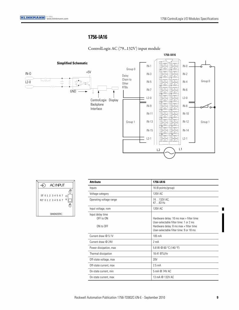
1756-IA16
ControlLogix AC (79...132V) input module
12
34
56
78
910
1112
1314
1516
1718
1920
L2 L1
Daisy Chain to OtherRTBs
1756-IA16
Group 0
Group 0
Group 1Group 1
IN-1
IN-3
IN-5
IN-7
L2-0
IN-9
IN-11
IN-13
IN-15
L2-1
IN-0
IN-2
IN-4
IN-6
L2-0
IN-8
IN-10
IN-12
IN-14
L2-1
Simplified Schematic
ControlLogix Backplane Interface
Display
+5V
L2-0
IN-O
GND
Attribute 1756-IA16
Inputs 16 (8 points/group)
Voltage category 120V AC
Operating voltage range 74…132V AC,47…63 Hz
Input voltage, nom 120V AC
Input delay timeOFF to ON
ON to OFF
Hardware delay: 10 ms max + filter timeUser-selectable filter time: 1 or 2 msHardware delay: 8 ms max + filter timeUser-selectable filter time: 9 or 18 ms
Current draw @ 5.1V 105 mA
Current draw @ 24V 2 mA
Power dissipation, max 5.8 W @ 60 °C (140 °F)
Thermal dissipation 18.41 BTU/hr
Off-state voltage, max 20V
Off-state current, max 2.5 mA
On-state current, min 5 mA @ 74V AC
On-state current, max 13 mA @ 132V AC
AC INPUT
ST
FLT
0 1 2 3 4 5 6 7
0 1 2 3 4 5 6 7OK
DIAGNOSTIC
Rockwell Automation Publication 1756-TD002C-EN-E - September 2010 9
1756 ControlLogix I/O Modules Specifications www.klinkmann.com6 / 2011
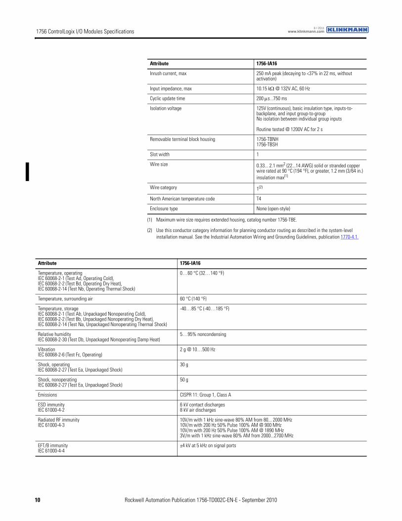
Inrush current, max 250 mA peak (decaying to <37% in 22 ms, without activation)
Input impedance, max 10.15 kΩ @ 132V AC, 60 Hz
Cyclic update time 200 μs...750 ms
Isolation voltage 125V (continuous), basic insulation type, inputs-to-backplane, and input group-to-groupNo isolation between individual group inputs
Routine tested @ 1200V AC for 2 s
Removable terminal block housing 1756-TBNH1756-TBSH
Slot width 1
Wire size 0.33... 2.1 mm2 (22...14 AWG) solid or stranded copper wire rated at 90 °C (194 °F), or greater, 1.2 mm (3/64 in.) insulation max(1)
Wire category 1(2)
North American temperature code T4
Enclosure type None (open-style)
(1) Maximum wire size requires extended housing, catalog number 1756-TBE.
(2) Use this conductor category information for planning conductor routing as described in the system-level installation manual. See the Industrial Automation Wiring and Grounding Guidelines, publication 1770-4.1.
Attribute 1756-IA16
Attribute 1756-IA16
Temperature, operatingIEC 60068-2-1 (Test Ad, Operating Cold),IEC 60068-2-2 (Test Bd, Operating Dry Heat),IEC 60068-2-14 (Test Nb, Operating Thermal Shock)
0…60 °C (32…140 °F)
Temperature, surrounding air 60 °C (140 °F)
Temperature, storageIEC 60068-2-1 (Test Ab, Unpackaged Nonoperating Cold),IEC 60068-2-2 (Test Bb, Unpackaged Nonoperating Dry Heat),IEC 60068-2-14 (Test Na, Unpackaged Nonoperating Thermal Shock)
-40…85 °C (-40…185 °F)
Relative humidityIEC 60068-2-30 (Test Db, Unpackaged Nonoperating Damp Heat)
5…95% noncondensing
VibrationIEC 60068-2-6 (Test Fc, Operating)
2 g @ 10…500 Hz
Shock, operatingIEC 60068-2-27 (Test Ea, Unpackaged Shock)
30 g
Shock, nonoperatingIEC 60068-2-27 (Test Ea, Unpackaged Shock)
50 g
Emissions CISPR 11: Group 1, Class A
ESD immunityIEC 61000-4-2
6 kV contact discharges8 kV air discharges
Radiated RF immunityIEC 61000-4-3
10V/m with 1 kHz sine-wave 80% AM from 80... 2000 MHz10V/m with 200 Hz 50% Pulse 100% AM @ 900 MHz10V/m with 200 Hz 50% Pulse 100% AM @ 1890 MHz3V/m with 1 kHz sine-wave 80% AM from 2000...2700 MHz
EFT/B immunityIEC 61000-4-4
±4 kV at 5 kHz on signal ports
10 Rockwell Automation Publication 1756-TD002C-EN-E - September 2010
1756 ControlLogix I/O Modules Specificationswww.klinkmann.com6 / 2011
Surge transient immunityIEC 61000-4-5
±1 kV line-line (DM) and ±2 kV line-earth (CM) on signal ports
Conducted RF immunityIEC 61000-4-6
10Vrms with 1 kHz sine-wave 80% AM from 150 kHz...80 MHz
Oscillatory surge withstandIEEE C37.90.1
3 kV
Attribute 1756-IA16
Certification(1) 1756-IA16
UL UL Listed Industrial Control Equipment, certified for US and Canada. See UL File E65584.
CSA CSA Certified Process Control Equipment. See CSA File LR54689C.
CSA Certified Process Control Equipment for Class I, Division 2 Group A,B,C,D Hazardous Locations. See CSA File LR69960C.
CE European Union 2004/108/IEC EMC Directive, compliant with:• EN 61326-1; Meas./Control/Lab., Industrial Requirements
• EN 61000-6-2; Industrial Immunity
• EN 61000-6-4; Industrial Emissions
• EN 61131-2; Programmable Controllers (Clause 8, Zone A & B)
European Union 2006/95/EC LVD, compliant with:• EN 61131-2; Programmable Controllers
C-Tick Australian Radiocommunications Act, compliant with:AS/NZS CISPR 11; Industrial Emissions
FM FM Approved Equipment for use in Class I Division 2 Group A,B,C,D Hazardous Locations
(1) When marked. See the Product Certification link at http://www.ab.com for Declarations of Conformity, Certificates, and other certification details.
Rockwell Automation Publication 1756-TD002C-EN-E - September 2010 11
1756 ControlLogix I/O Modules Specifications www.klinkmann.com6 / 2011
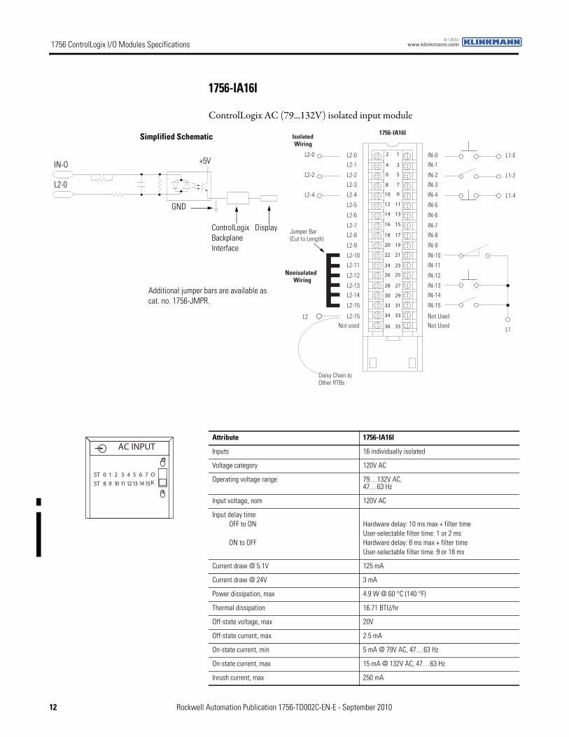
1756-IA16I
ControlLogix AC (79...132V) isolated input module
Nonisolated Wiring
IsolatedWiring
12
34
56
78
910
1112
1314
1516
1718
1920
2122
2324
2526
2728
2930
3132
3334
3536
Daisy Chain to Other RTBs
L2-0
1756-IA16I
L2-0L2-1
L2-2
L2-3
L2-8
L2-4
L2-5
L2-6
L2-7
Not used
L2-9
L2-10
L2-11
L2-12
L2-13L2-14
L2-15
L2-15
IN-0IN-1
IN-2
IN-3
IN-8
IN-4
IN-5
IN-6
IN-7
Not Used
IN-9
IN-10
IN-11
IN-12
IN-13IN-14
IN-15
Not Used
L2-2
L2-4
L2
L1
L1-0
L1-2
L1-4
Jumper Bar (Cut to Length)
ControlLogix Backplane Interface
Display
Simplified Schematic
+5V
L2-0
IN-O
GND
Additional jumper bars are available as cat. no. 1756-JMPR.
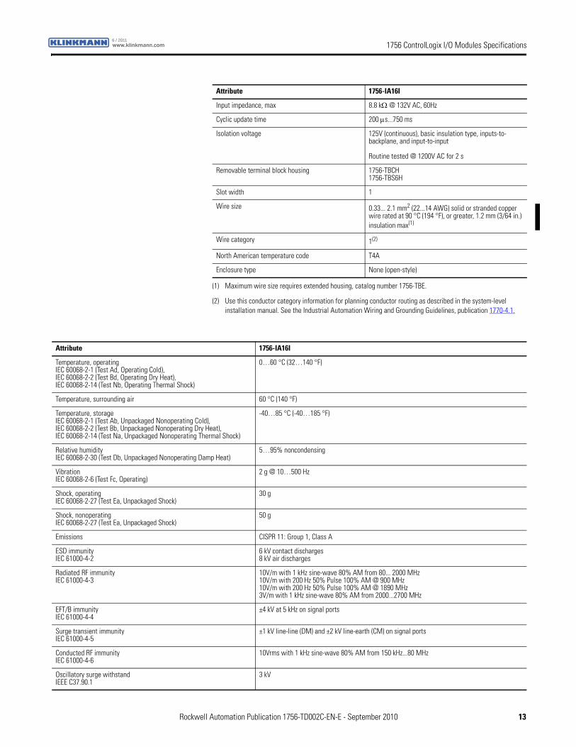
Attribute 1756-IA16I
Inputs 16 individually isolated
Voltage category 120V AC
Operating voltage range 79…132V AC,47…63 Hz
Input voltage, nom 120V AC
Input delay timeOFF to ON
ON to OFF
Hardware delay: 10 ms max + filter timeUser-selectable filter time: 1 or 2 msHardware delay: 8 ms max + filter timeUser-selectable filter time: 9 or 18 ms
Current draw @ 5.1V 125 mA
Current draw @ 24V 3 mA
Power dissipation, max 4.9 W @ 60 °C (140 °F)
Thermal dissipation 16.71 BTU/hr
Off-state voltage, max 20V
Off-state current, max 2.5 mA
On-state current, min 5 mA @ 79V AC, 47…63 Hz
On-state current, max 15 mA @ 132V AC, 47…63 Hz
Inrush current, max 250 mA
ST 0 1 2 3 4 5 6 7
ST 8 9 10 11 12 13 14 15
OK
AC INPUT
12 Rockwell Automation Publication 1756-TD002C-EN-E - September 2010
1756 ControlLogix I/O Modules Specificationswww.klinkmann.com6 / 2011
Input impedance, max 8.8 kΩ @ 132V AC, 60Hz
Cyclic update time 200 μs...750 ms
Isolation voltage 125V (continuous), basic insulation type, inputs-to-backplane, and input-to-input
Routine tested @ 1200V AC for 2 s
Removable terminal block housing 1756-TBCH1756-TBS6H
Slot width 1
Wire size 0.33... 2.1 mm2 (22...14 AWG) solid or stranded copper wire rated at 90 °C (194 °F), or greater, 1.2 mm (3/64 in.) insulation max(1)
Wire category 1(2)
North American temperature code T4A
Enclosure type None (open-style)
(1) Maximum wire size requires extended housing, catalog number 1756-TBE.
(2) Use this conductor category information for planning conductor routing as described in the system-level installation manual. See the Industrial Automation Wiring and Grounding Guidelines, publication 1770-4.1.
Attribute 1756-IA16I
Attribute 1756-IA16I
Temperature, operatingIEC 60068-2-1 (Test Ad, Operating Cold),IEC 60068-2-2 (Test Bd, Operating Dry Heat),IEC 60068-2-14 (Test Nb, Operating Thermal Shock)
0…60 °C (32…140 °F)
Temperature, surrounding air 60 °C (140 °F)
Temperature, storageIEC 60068-2-1 (Test Ab, Unpackaged Nonoperating Cold),IEC 60068-2-2 (Test Bb, Unpackaged Nonoperating Dry Heat),IEC 60068-2-14 (Test Na, Unpackaged Nonoperating Thermal Shock)
-40…85 °C (-40…185 °F)
Relative humidityIEC 60068-2-30 (Test Db, Unpackaged Nonoperating Damp Heat)
5…95% noncondensing
VibrationIEC 60068-2-6 (Test Fc, Operating)
2 g @ 10…500 Hz
Shock, operatingIEC 60068-2-27 (Test Ea, Unpackaged Shock)
30 g
Shock, nonoperatingIEC 60068-2-27 (Test Ea, Unpackaged Shock)
50 g
Emissions CISPR 11: Group 1, Class A
ESD immunityIEC 61000-4-2
6 kV contact discharges8 kV air discharges
Radiated RF immunityIEC 61000-4-3
10V/m with 1 kHz sine-wave 80% AM from 80... 2000 MHz10V/m with 200 Hz 50% Pulse 100% AM @ 900 MHz10V/m with 200 Hz 50% Pulse 100% AM @ 1890 MHz3V/m with 1 kHz sine-wave 80% AM from 2000...2700 MHz
EFT/B immunityIEC 61000-4-4
±4 kV at 5 kHz on signal ports
Surge transient immunityIEC 61000-4-5
±1 kV line-line (DM) and ±2 kV line-earth (CM) on signal ports
Conducted RF immunityIEC 61000-4-6
10Vrms with 1 kHz sine-wave 80% AM from 150 kHz...80 MHz
Oscillatory surge withstandIEEE C37.90.1
3 kV
Rockwell Automation Publication 1756-TD002C-EN-E - September 2010 13
1756 ControlLogix I/O Modules Specifications www.klinkmann.com6 / 2011
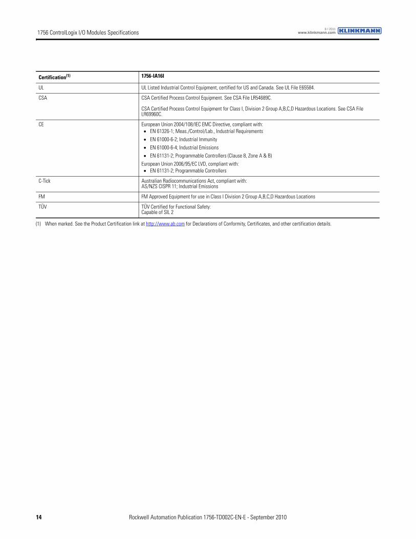
Certification(1) 1756-IA16I
UL UL Listed Industrial Control Equipment, certified for US and Canada. See UL File E65584.
CSA CSA Certified Process Control Equipment. See CSA File LR54689C.
CSA Certified Process Control Equipment for Class I, Division 2 Group A,B,C,D Hazardous Locations. See CSA File LR69960C.
CE European Union 2004/108/IEC EMC Directive, compliant with:• EN 61326-1; Meas./Control/Lab., Industrial Requirements
• EN 61000-6-2; Industrial Immunity
• EN 61000-6-4; Industrial Emissions
• EN 61131-2; Programmable Controllers (Clause 8, Zone A & B)
European Union 2006/95/EC LVD, compliant with:• EN 61131-2; Programmable Controllers
C-Tick Australian Radiocommunications Act, compliant with:AS/NZS CISPR 11; Industrial Emissions
FM FM Approved Equipment for use in Class I Division 2 Group A,B,C,D Hazardous Locations
TÜV TÜV Certified for Functional Safety:Capable of SIL 2
(1) When marked. See the Product Certification link at http://www.ab.com for Declarations of Conformity, Certificates, and other certification details.
14 Rockwell Automation Publication 1756-TD002C-EN-E - September 2010
1756 ControlLogix I/O Modules Specificationswww.klinkmann.com6 / 2011
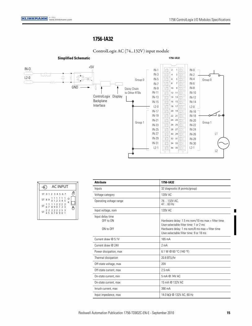
1756-IA32
ControlLogix AC (74...132V) input module
12
34
56
78
910
1112
1314
1516
1718
1920
2122
2324
2526
2728
2930
3132
3334
3536
IN-0IN-2IN-4IN-6IN-8IN-10IN-12IN-14
IN-16IN-18IN-20IN-22IN-24IN-26IN-28IN-30L2-1
L2-0
IN-1IN-3IN-5IN-7IN-9
IN-11IN-13IN-15L2-0
IN-17IN-19IN-21IN-23IN-25IN-27IN-29IN-31L2-1
L1
L2
Daisy Chain to Other RTBs
1 puorG1 puorG
0 puorG0 puorG
1756-IA32Simplified Schematic
ControlLogix Backplane Interface
Display
+5V
L2-0
IN-O
GND
Attribute 1756-IA32
Inputs 32 diagnostic (4 points/group)
Voltage category 120V AC
Operating voltage range 74…132V AC,47…63 Hz
Input voltage, nom 120V AC
Input delay timeOFF to ON
ON to OFF
Hardware delay: 1.5 ms nom/10 ms max + filter timeUser-selectable filter time: 1 or 2 msHardware delay: 1 ms nom/8 ms max + filter timeUser-selectable filter time: 9 or 18 ms
Current draw @ 5.1V 165 mA
Current draw @ 24V 2 mA
Power dissipation, max 6.1 W @ 60 °C (140 °F)
Thermal dissipation 20.8 BTU/hr
Off-state voltage, max 20V
Off-state current, max 2.5 mA
On-state current, min 5 mA @ 74V AC
On-state current, max 15 mA @ 132V AC
Inrush current, max 390 mA
Input impedance, max 14.0 kΩ @ 132V AC, 60 Hz
AC INPUT
OK
ST 0 1 2 3 4 5 6 7
ST 8 910 21 3 4 5
1 1 1 11
ST 6 718 09 1 2 3
1 2 2 221 1
ST 4 526 87 9 0 1
2 2 2 332 2
Rockwell Automation Publication 1756-TD002C-EN-E - September 2010 15
1756 ControlLogix I/O Modules Specifications www.klinkmann.com6 / 2011
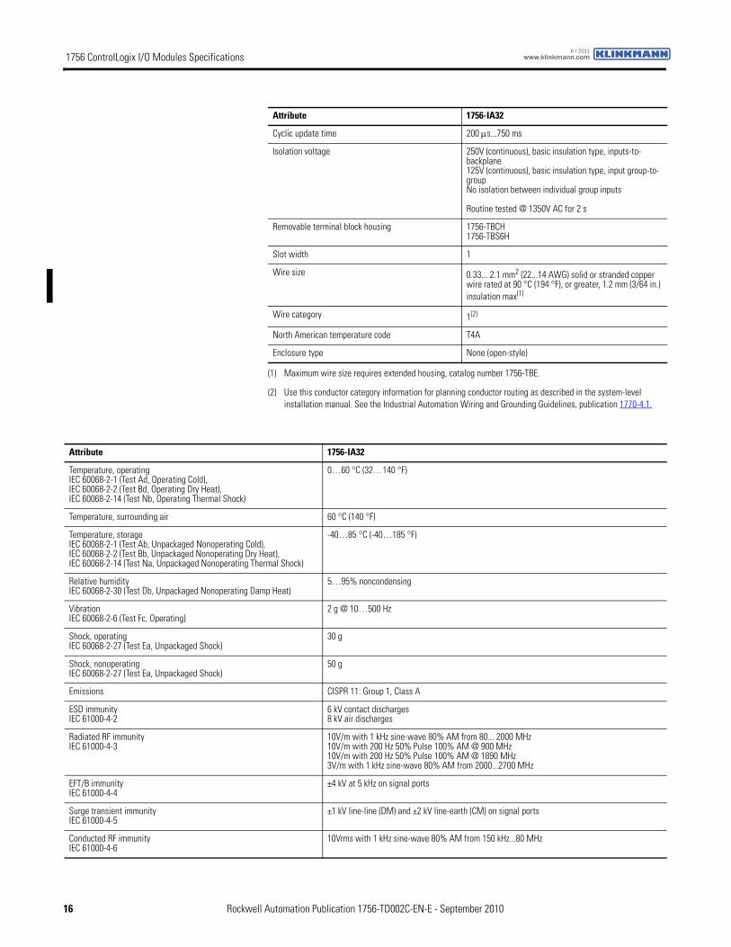
Cyclic update time 200 μs...750 ms
Isolation voltage 250V (continuous), basic insulation type, inputs-to-backplane125V (continuous), basic insulation type, input group-to-groupNo isolation between individual group inputs
Routine tested @ 1350V AC for 2 s
Removable terminal block housing 1756-TBCH1756-TBS6H
Slot width 1
Wire size 0.33... 2.1 mm2 (22...14 AWG) solid or stranded copper wire rated at 90 °C (194 °F), or greater, 1.2 mm (3/64 in.) insulation max(1)
Wire category 1(2)
North American temperature code T4A
Enclosure type None (open-style)
(1) Maximum wire size requires extended housing, catalog number 1756-TBE.
(2) Use this conductor category information for planning conductor routing as described in the system-level installation manual. See the Industrial Automation Wiring and Grounding Guidelines, publication 1770-4.1.
Attribute 1756-IA32
Attribute 1756-IA32
Temperature, operatingIEC 60068-2-1 (Test Ad, Operating Cold),IEC 60068-2-2 (Test Bd, Operating Dry Heat),IEC 60068-2-14 (Test Nb, Operating Thermal Shock)
0…60 °C (32…140 °F)
Temperature, surrounding air 60 °C (140 °F)
Temperature, storageIEC 60068-2-1 (Test Ab, Unpackaged Nonoperating Cold),IEC 60068-2-2 (Test Bb, Unpackaged Nonoperating Dry Heat),IEC 60068-2-14 (Test Na, Unpackaged Nonoperating Thermal Shock)
-40…85 °C (-40…185 °F)
Relative humidityIEC 60068-2-30 (Test Db, Unpackaged Nonoperating Damp Heat)
5…95% noncondensing
VibrationIEC 60068-2-6 (Test Fc, Operating)
2 g @ 10…500 Hz
Shock, operatingIEC 60068-2-27 (Test Ea, Unpackaged Shock)
30 g
Shock, nonoperatingIEC 60068-2-27 (Test Ea, Unpackaged Shock)
50 g
Emissions CISPR 11: Group 1, Class A
ESD immunityIEC 61000-4-2
6 kV contact discharges8 kV air discharges
Radiated RF immunityIEC 61000-4-3
10V/m with 1 kHz sine-wave 80% AM from 80... 2000 MHz10V/m with 200 Hz 50% Pulse 100% AM @ 900 MHz10V/m with 200 Hz 50% Pulse 100% AM @ 1890 MHz3V/m with 1 kHz sine-wave 80% AM from 2000...2700 MHz
EFT/B immunityIEC 61000-4-4
±4 kV at 5 kHz on signal ports
Surge transient immunityIEC 61000-4-5
±1 kV line-line (DM) and ±2 kV line-earth (CM) on signal ports
Conducted RF immunityIEC 61000-4-6
10Vrms with 1 kHz sine-wave 80% AM from 150 kHz...80 MHz
16 Rockwell Automation Publication 1756-TD002C-EN-E - September 2010
1756 ControlLogix I/O Modules Specificationswww.klinkmann.com6 / 2011
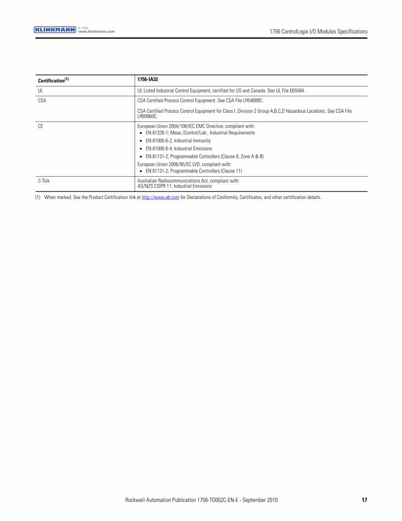
Certification(1) 1756-IA32
UL UL Listed Industrial Control Equipment, certified for US and Canada. See UL File E65584.
CSA CSA Certified Process Control Equipment. See CSA File LR54689C.
CSA Certified Process Control Equipment for Class I, Division 2 Group A,B,C,D Hazardous Locations. See CSA File LR69960C.
CE European Union 2004/108/IEC EMC Directive, compliant with:• EN 61326-1; Meas./Control/Lab., Industrial Requirements
• EN 61000-6-2; Industrial Immunity
• EN 61000-6-4; Industrial Emissions
• EN 61131-2; Programmable Controllers (Clause 8, Zone A & B)
European Union 2006/95/EC LVD, compliant with:• EN 61131-2; Programmable Controllers (Clause 11)
C-Tick Australian Radiocommunications Act, compliant with:AS/NZS CISPR 11; Industrial Emissions
(1) When marked. See the Product Certification link at http://www.ab.com for Declarations of Conformity, Certificates, and other certification details.
Rockwell Automation Publication 1756-TD002C-EN-E - September 2010 17
1756 ControlLogix I/O Modules Specifications www.klinkmann.com6 / 2011
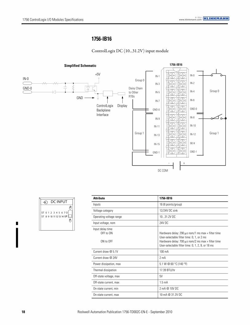
1756-IB16
ControlLogix DC (10...31.2V) input module
1756-IB16
IN-9
IN-11
IN-13
IN-15
GND-1
IN-1
IN-3
IN-5
IN-7
GND-0
IN-8
IN-10
IN-12
IN14
GND-1
IN-0
IN-2
IN-4
IN-6
GND-0
?
??
??
??
?
?
??
??
??
??
Daisy Chain to Other RTBs
Group 0
Group 0
Group 1Group 1
DC COM
- +
ControlLogix Backplane Interface
Simplified Schematic
Display
GND
GND-0
IN-0+5V
Attribute 1756-IB16
Inputs 16 (8 points/group)
Voltage category 12/24V DC sink
Operating voltage range 10...31.2V DC
Input voltage, nom 24V DC
Input delay timeOFF to ON
ON to OFF
Hardware delay: 290 μs nom/1 ms max + filter timeUser-selectable filter time: 0, 1, or 2 msHardware delay: 700 μs nom/2 ms max + filter timeUser-selectable filter time: 0, 1, 2, 9, or 18 ms
Current draw @ 5.1V 100 mA
Current draw @ 24V 2 mA
Power dissipation, max 5.1 W @ 60 °C (140 °F)
Thermal dissipation 17.39 BTU/hr
Off-state voltage, max 5V
Off-state current, max 1.5 mA
On-state current, min 2 mA @ 10V DC
On-state current, max 10 mA @ 31.2V DC
DC INPUT
ST 0 1 2 3 4 5 6 7
ST 8 9 10 11 12 13 14 15
OK
18 Rockwell Automation Publication 1756-TD002C-EN-E - September 2010
1756 ControlLogix I/O Modules Specificationswww.klinkmann.com6 / 2011
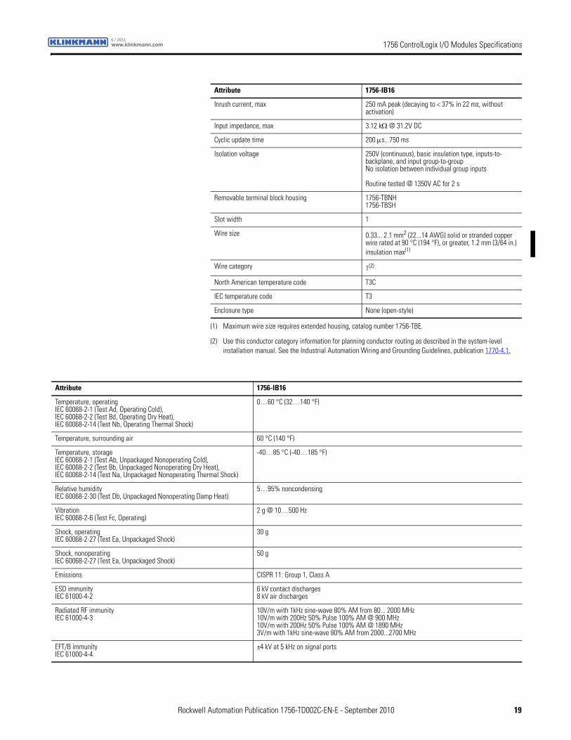
Inrush current, max 250 mA peak (decaying to < 37% in 22 ms, without activation)
Input impedance, max 3.12 kΩ @ 31.2V DC
Cyclic update time 200 μs...750 ms
Isolation voltage 250V (continuous), basic insulation type, inputs-to-backplane, and input group-to-groupNo isolation between individual group inputs
Routine tested @ 1350V AC for 2 s
Removable terminal block housing 1756-TBNH1756-TBSH
Slot width 1
Wire size 0.33... 2.1 mm2 (22...14 AWG) solid or stranded copper wire rated at 90 °C (194 °F), or greater, 1.2 mm (3/64 in.) insulation max(1)
Wire category 1(2)
North American temperature code T3C
IEC temperature code T3
Enclosure type None (open-style)
(1) Maximum wire size requires extended housing, catalog number 1756-TBE.
(2) Use this conductor category information for planning conductor routing as described in the system-level installation manual. See the Industrial Automation Wiring and Grounding Guidelines, publication 1770-4.1.
Attribute 1756-IB16
Attribute 1756-IB16
Temperature, operatingIEC 60068-2-1 (Test Ad, Operating Cold),IEC 60068-2-2 (Test Bd, Operating Dry Heat),IEC 60068-2-14 (Test Nb, Operating Thermal Shock)
0…60 °C (32…140 °F)
Temperature, surrounding air 60 °C (140 °F)
Temperature, storageIEC 60068-2-1 (Test Ab, Unpackaged Nonoperating Cold),IEC 60068-2-2 (Test Bb, Unpackaged Nonoperating Dry Heat),IEC 60068-2-14 (Test Na, Unpackaged Nonoperating Thermal Shock)
-40…85 °C (-40…185 °F)
Relative humidityIEC 60068-2-30 (Test Db, Unpackaged Nonoperating Damp Heat)
5…95% noncondensing
VibrationIEC 60068-2-6 (Test Fc, Operating)
2 g @ 10…500 Hz
Shock, operatingIEC 60068-2-27 (Test Ea, Unpackaged Shock)
30 g
Shock, nonoperatingIEC 60068-2-27 (Test Ea, Unpackaged Shock)
50 g
Emissions CISPR 11: Group 1, Class A
ESD immunityIEC 61000-4-2
6 kV contact discharges8 kV air discharges
Radiated RF immunityIEC 61000-4-3
10V/m with 1kHz sine-wave 80% AM from 80... 2000 MHz10V/m with 200Hz 50% Pulse 100% AM @ 900 MHz10V/m with 200Hz 50% Pulse 100% AM @ 1890 MHz3V/m with 1kHz sine-wave 80% AM from 2000...2700 MHz
EFT/B immunityIEC 61000-4-4
±4 kV at 5 kHz on signal ports
Rockwell Automation Publication 1756-TD002C-EN-E - September 2010 19

1756 ControlLogix I/O Modules Specifications www.klinkmann.com6 / 2011
Surge transient immunityIEC 61000-4-5
±1 kV line-line (DM) and ±2 kV line-earth (CM) on signal ports
Conducted RF immunityIEC 61000-4-6
10Vrms with 1 kHz sine-wave 80% AM from 150 kHz...80 MHz
Oscillatory surge withstandIEEE C37.90.1
3 kV
Attribute 1756-IB16
Certification(1) 1756-IB16
UL UL Listed Industrial Control Equipment, certified for US and Canada. See UL File E65584.
CSA CSA Certified Process Control Equipment. See CSA File LR54689C.
CSA Certified Process Control Equipment for Class I, Division 2 Group A,B,C,D Hazardous Locations. See CSA File LR69960C.
CE European Union 2004/108/IEC EMC Directive, compliant with:• EN 61326-1; Meas./Control/Lab., Industrial Requirements
• EN 61000-6-2; Industrial Immunity
• EN 61000-6-4; Industrial Emissions
• EN 61131-2; Programmable Controllers (Clause 8, Zone A & B)
European Union 2006/95/EC LVD, compliant with:• EN 61131-2; Programmable Controllers (Clause 11)
C-Tick Australian Radiocommunications Act, compliant with:AS/NZS CISPR 11; Industrial Emissions
Ex European Union 94/9/EC ATEX Directive, compliant with:• EN 60079-15; Potentially Explosive Atmospheres, Protection "n"
• EN 60079-0; General Requirements II 3 G Ex nA IIC T3 X
FM FM Approved Equipment for use in Class I Division 2 Group A,B,C,D Hazardous Locations
(1) When marked. See the Product Certification link at http://www.ab.com for Declarations of Conformity, Certificates, and other certification details.
20 Rockwell Automation Publication 1756-TD002C-EN-E - September 2010
1756 ControlLogix I/O Modules Specificationswww.klinkmann.com6 / 2011
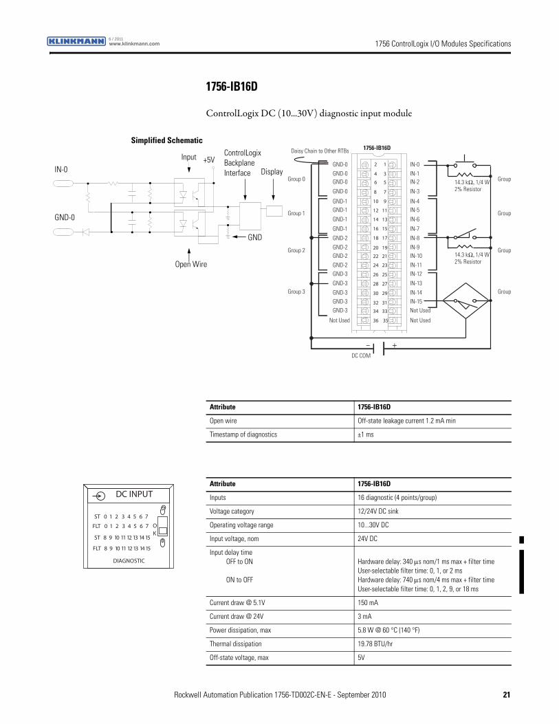
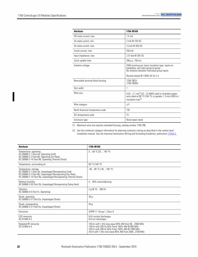
1756-IB16D
ControlLogix DC (10...30V) diagnostic input module
12
34
56
78
910
1112
1314
1516
1718
1920
2122
2324
2526
2728
2930
3132
3334
3536
+–
14.3 kΩ, 1/4 W 2% Resistor
14.3 kΩ, 1/4 W 2% Resistor
Daisy Chain to Other RTBs
Group 0
Group 1
1756-IB16D
Group 2
Group 3
Group
Group
Group
Group
IN-0IN-1IN-2
IN-3
IN-8
IN-4IN-5
IN-6
IN-7
Not Used
IN-9IN-10
IN-11IN-12
IN-13
IN-14IN-15Not Used
GND-0GND-0GND-0
GND-0
GND-2
GND-1GND-1
GND-1
GND-1
Not Used
GND-2GND-2
GND-2GND-3
GND-3
GND-3GND-3GND-3
DC COM
ControlLogix Backplane Interface
Simplified Schematic
Display
GND
Open Wire
GND-0
IN-0
Input +5V
Attribute 1756-IB16D
Open wire Off-state leakage current 1.2 mA min
Timestamp of diagnostics ±1 ms
Attribute 1756-IB16D
Inputs 16 diagnostic (4 points/group)
Voltage category 12/24V DC sink
Operating voltage range 10...30V DC
Input voltage, nom 24V DC
Input delay timeOFF to ON
ON to OFF
Hardware delay: 340 μs nom/1 ms max + filter timeUser-selectable filter time: 0, 1, or 2 msHardware delay: 740 μs nom/4 ms max + filter timeUser-selectable filter time: 0, 1, 2, 9, or 18 ms
Current draw @ 5.1V 150 mA
Current draw @ 24V 3 mA
Power dissipation, max 5.8 W @ 60 °C (140 °F)
Thermal dissipation 19.78 BTU/hr
Off-state voltage, max 5V
FLT 8 9 10 11 12 13 14 15
ST 0 1 2 3 4 5 6 7
ST 8 9 10 11 12 13 14 15
OK
FLT 0 1 2 3 4 5 6 7
DC INPUT
DIAGNOSTIC
Rockwell Automation Publication 1756-TD002C-EN-E - September 2010 21
1756 ControlLogix I/O Modules Specifications www.klinkmann.com6 / 2011
Off-state current, max 1.5 mA
On-state current, min 2 mA @ 10V DC
On-state current, max 13 mA @ 30V DC
Inrush current, max 250 mA
Input impedance, max 2.31 kΩ @ 30V DC
Cyclic update time 200 μs...750 ms
Isolation voltage 250V (continuous), basic insulation type, inputs-to-backplane, and input group-to-groupNo isolation between individual group inputs
Routine tested @ 1350V AC for 2 s
Removable terminal block housing 1756-TBCH1756-TBS6H
Slot width 1
Wire size 0.33... 2.1 mm2 (22...14 AWG) solid or stranded copper wire rated at 90 °C (194 °F), or greater, 1.2 mm (3/64 in.) insulation max(1)
Wire category 1(2)
North American temperature code T3C
IEC temperature code T3
Enclosure type None (open-style)
(1) Maximum wire size requires extended housing, catalog number 1756-TBE.
(2) Use this conductor category information for planning conductor routing as described in the system-level installation manual. See the Industrial Automation Wiring and Grounding Guidelines, publication 1770-4.1.
Attribute 1756-IB16D
Attribute 1756-IB16D
Temperature, operatingIEC 60068-2-1 (Test Ad, Operating Cold),IEC 60068-2-2 (Test Bd, Operating Dry Heat),IEC 60068-2-14 (Test Nb, Operating Thermal Shock)
0…60 °C (32…140 °F)
Temperature, surrounding air 60 °C (140 °F)
Temperature, storageIEC 60068-2-1 (Test Ab, Unpackaged Nonoperating Cold),IEC 60068-2-2 (Test Bb, Unpackaged Nonoperating Dry Heat),IEC 60068-2-14 (Test Na, Unpackaged Nonoperating Thermal Shock)
-40…85 °C (-40…185 °F)
Relative humidityIEC 60068-2-30 (Test Db, Unpackaged Nonoperating Damp Heat)
5…95% noncondensing
VibrationIEC 60068-2-6 (Test Fc, Operating)
2 g @ 10…500 Hz
Shock, operatingIEC 60068-2-27 (Test Ea, Unpackaged Shock)
30 g
Shock, nonoperatingIEC 60068-2-27 (Test Ea, Unpackaged Shock)
50 g
Emissions CISPR 11: Group 1, Class A
ESD immunityIEC 61000-4-2
6 kV contact discharges8 kV air discharges
Radiated RF immunityIEC 61000-4-3
10V/m with 1 kHz sine-wave 80% AM from 80... 2000 MHz10V/m with 200 Hz 50% Pulse 100% AM @ 900 MHz10V/m with 200 Hz 50% Pulse 100% AM @ 1890 MHz3V/m with 1 kHz sine-wave 80% AM from 2000...2700 MHz
22 Rockwell Automation Publication 1756-TD002C-EN-E - September 2010
1756 ControlLogix I/O Modules Specificationswww.klinkmann.com6 / 2011
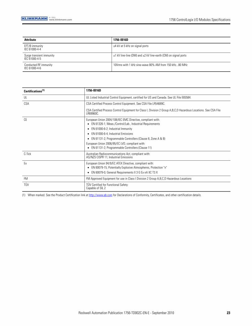
EFT/B immunityIEC 61000-4-4
±4 kV at 5 kHz on signal ports
Surge transient immunityIEC 61000-4-5
±1 kV line-line (DM) and ±2 kV line-earth (CM) on signal ports
Conducted RF immunityIEC 61000-4-6
10Vrms with 1 kHz sine-wave 80% AM from 150 kHz...80 MHz
Attribute 1756-IB16D
Certifications(1) 1756-IB16D
UL UL Listed Industrial Control Equipment, certified for US and Canada. See UL File E65584.
CSA CSA Certified Process Control Equipment. See CSA File LR54689C.
CSA Certified Process Control Equipment for Class I, Division 2 Group A,B,C,D Hazardous Locations. See CSA File LR69960C.
CE European Union 2004/108/IEC EMC Directive, compliant with:• EN 61326-1; Meas./Control/Lab., Industrial Requirements
• EN 61000-6-2; Industrial Immunity
• EN 61000-6-4; Industrial Emissions
• EN 61131-2; Programmable Controllers (Clause 8, Zone A & B)
European Union 2006/95/EC LVD, compliant with:• EN 61131-2; Programmable Controllers (Clause 11)
C-Tick Australian Radiocommunications Act, compliant with:AS/NZS CISPR 11; Industrial Emissions
Ex European Union 94/9/EC ATEX Directive, compliant with:• EN 60079-15; Potentially Explosive Atmospheres, Protection "n"
• EN 60079-0; General Requirements II 3 G Ex nA IIC T3 X
FM FM Approved Equipment for use in Class I Division 2 Group A,B,C,D Hazardous Locations
TÜV TÜV Certified for Functional Safety:Capable of SIL 2
(1) When marked. See the Product Certification link at http://www.ab.com for Declarations of Conformity, Certificates, and other certification details.
Rockwell Automation Publication 1756-TD002C-EN-E - September 2010 23
1756 ControlLogix I/O Modules Specifications www.klinkmann.com6 / 2011
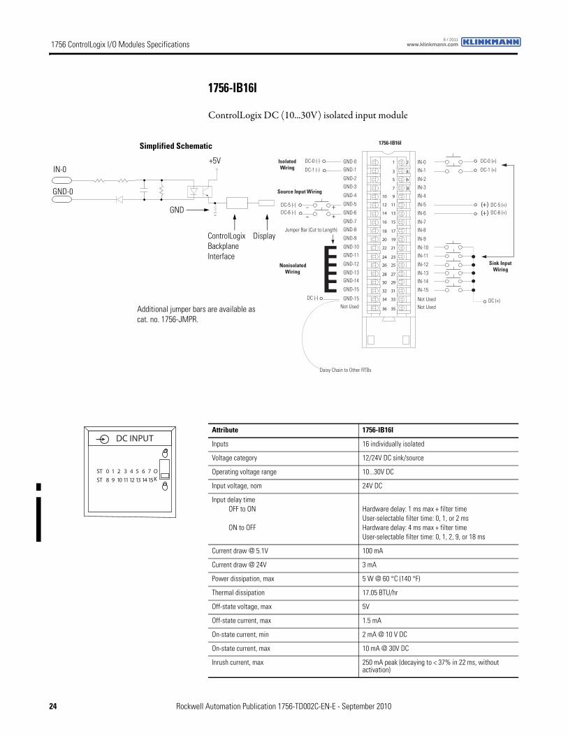
1756-IB16I
ControlLogix DC (10...30V) isolated input module
1 2
3 4
5 6
7 8
01 9
21 11
41 31
61 51
81 71
02 91
22 12
42 32
62 52
82 72
03 92
23 13
43 33
63 53
(+)(+)
+–
+–
NonisolatedWiring
IsolatedWiring
Daisy Chain to Other RTBs
1756-IB16I
GND-0GND-1
GND-2
GND-3
GND-8
GND-4
GND-5
GND-6
GND-7
Not Used
GND-9
GND-10
GND-11
GND-12
GND-13GND-14
GND-15
GND-15
IN-0
IN-1
IN-2
IN-3
IN-8
IN-4
IN-5
IN-6
IN-7
Not Used
IN-9
IN-10
IN-11
IN-12
IN-13
IN-14
IN-15
Not Used
DC-5 (-)
DC (-)
Jumper Bar (Cut to Length)
DC-6 (-)DC-5 (+)DC-6 (+)
DC (+)
DC-0 (+)
DC-1 (+)
DC-0 (-)
DC-1 (-)
Source Input Wiring
Sink Input Wiring
ControlLogix Backplane Interface
Simplified Schematic
Display
GND-0
GND
IN-0+5V
Additional jumper bars are available as cat. no. 1756-JMPR.
Attribute 1756-IB16I
Inputs 16 individually isolated
Voltage category 12/24V DC sink/source
Operating voltage range 10...30V DC
Input voltage, nom 24V DC
Input delay timeOFF to ON
ON to OFF
Hardware delay: 1 ms max + filter timeUser-selectable filter time: 0, 1, or 2 msHardware delay: 4 ms max + filter timeUser-selectable filter time: 0, 1, 2, 9, or 18 ms
Current draw @ 5.1V 100 mA
Current draw @ 24V 3 mA
Power dissipation, max 5 W @ 60 °C (140 °F)
Thermal dissipation 17.05 BTU/hr
Off-state voltage, max 5V
Off-state current, max 1.5 mA
On-state current, min 2 mA @ 10 V DC
On-state current, max 10 mA @ 30V DC
Inrush current, max 250 mA peak (decaying to < 37% in 22 ms, without activation)
DC INPUT
ST 0 1 2 3 4 5 6 7
ST 8 9 10 11 12 13 14 15
OK
24 Rockwell Automation Publication 1756-TD002C-EN-E - September 2010
1756 ControlLogix I/O Modules Specificationswww.klinkmann.com6 / 2011
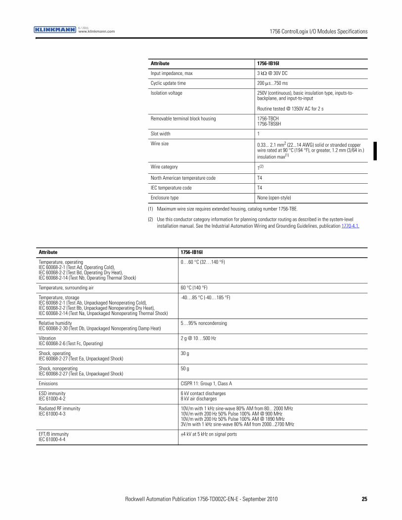
Input impedance, max 3 kΩ @ 30V DC
Cyclic update time 200 μs...750 ms
Isolation voltage 250V (continuous), basic insulation type, inputs-to-backplane, and input-to-input
Routine tested @ 1350V AC for 2 s
Removable terminal block housing 1756-TBCH1756-TBS6H
Slot width 1
Wire size 0.33... 2.1 mm2 (22...14 AWG) solid or stranded copper wire rated at 90 °C (194 °F), or greater, 1.2 mm (3/64 in.) insulation max(1)
Wire category 1(2)
North American temperature code T4
IEC temperature code T4
Enclosure type None (open-style)
(1) Maximum wire size requires extended housing, catalog number 1756-TBE.
(2) Use this conductor category information for planning conductor routing as described in the system-level installation manual. See the Industrial Automation Wiring and Grounding Guidelines, publication 1770-4.1.
Attribute 1756-IB16I
Attribute 1756-IB16I
Temperature, operatingIEC 60068-2-1 (Test Ad, Operating Cold),IEC 60068-2-2 (Test Bd, Operating Dry Heat),IEC 60068-2-14 (Test Nb, Operating Thermal Shock)
0…60 °C (32…140 °F)
Temperature, surrounding air 60 °C (140 °F)
Temperature, storageIEC 60068-2-1 (Test Ab, Unpackaged Nonoperating Cold),IEC 60068-2-2 (Test Bb, Unpackaged Nonoperating Dry Heat),IEC 60068-2-14 (Test Na, Unpackaged Nonoperating Thermal Shock)
-40…85 °C (-40…185 °F)
Relative humidityIEC 60068-2-30 (Test Db, Unpackaged Nonoperating Damp Heat)
5…95% noncondensing
VibrationIEC 60068-2-6 (Test Fc, Operating)
2 g @ 10…500 Hz
Shock, operatingIEC 60068-2-27 (Test Ea, Unpackaged Shock)
30 g
Shock, nonoperatingIEC 60068-2-27 (Test Ea, Unpackaged Shock)
50 g
Emissions CISPR 11: Group 1, Class A
ESD immunityIEC 61000-4-2
6 kV contact discharges8 kV air discharges
Radiated RF immunityIEC 61000-4-3
10V/m with 1 kHz sine-wave 80% AM from 80... 2000 MHz10V/m with 200 Hz 50% Pulse 100% AM @ 900 MHz10V/m with 200 Hz 50% Pulse 100% AM @ 1890 MHz3V/m with 1 kHz sine-wave 80% AM from 2000...2700 MHz
EFT/B immunityIEC 61000-4-4
±4 kV at 5 kHz on signal ports
Rockwell Automation Publication 1756-TD002C-EN-E - September 2010 25

1756 ControlLogix I/O Modules Specifications www.klinkmann.com6 / 2011
Surge transient immunityIEC 61000-4-5
±1 kV line-line (DM) and ±2 kV line-earth (CM) on signal ports
Conducted RF immunityIEC 61000-4-6
10Vrms with 1 kHz sine-wave 80% AM from 150 kHz...80 MHz
Oscillatory surge withstandIEEE C37.90.1
3 kV
Attribute 1756-IB16I
Certification(1) 1756-IB16I
UL UL Listed Industrial Control Equipment, certified for US and Canada. See UL File E65584.
CSA CSA Certified Process Control Equipment. See CSA File LR54689C.
CSA Certified Process Control Equipment for Class I, Division 2 Group A,B,C,D Hazardous Locations. See CSA File LR69960C.
CE European Union 2004/108/IEC EMC Directive, compliant with:• EN 61326-1; Meas./Control/Lab., Industrial Requirements
• EN 61000-6-2; Industrial Immunity
• EN 61000-6-4; Industrial Emissions
• EN 61131-2; Programmable Controllers (Clause 8, Zone A & B)
European Union 2006/95/EC LVD, compliant with:• EN 61131-2; Programmable Controllers (Clause 11)
C-Tick Australian Radiocommunications Act, compliant with:AS/NZS CISPR 11; Industrial Emissions
Ex European Union 94/9/EC ATEX Directive, compliant with:• EN 60079-15; Potentially Explosive Atmospheres, Protection "n"
• EN 60079-0; General Requirements II 3 G Ex nA IIC T4 X
FM FM Approved Equipment for use in Class I Division 2 Group A,B,C,D Hazardous Locations
TÜV TÜV Certified for Functional Safety:Capable of SIL 2
(1) When marked. See the Product Certification link at http://www.ab.com for Declarations of Conformity, Certificates, and other certification details.
26 Rockwell Automation Publication 1756-TD002C-EN-E - September 2010
1756 ControlLogix I/O Modules Specificationswww.klinkmann.com6 / 2011
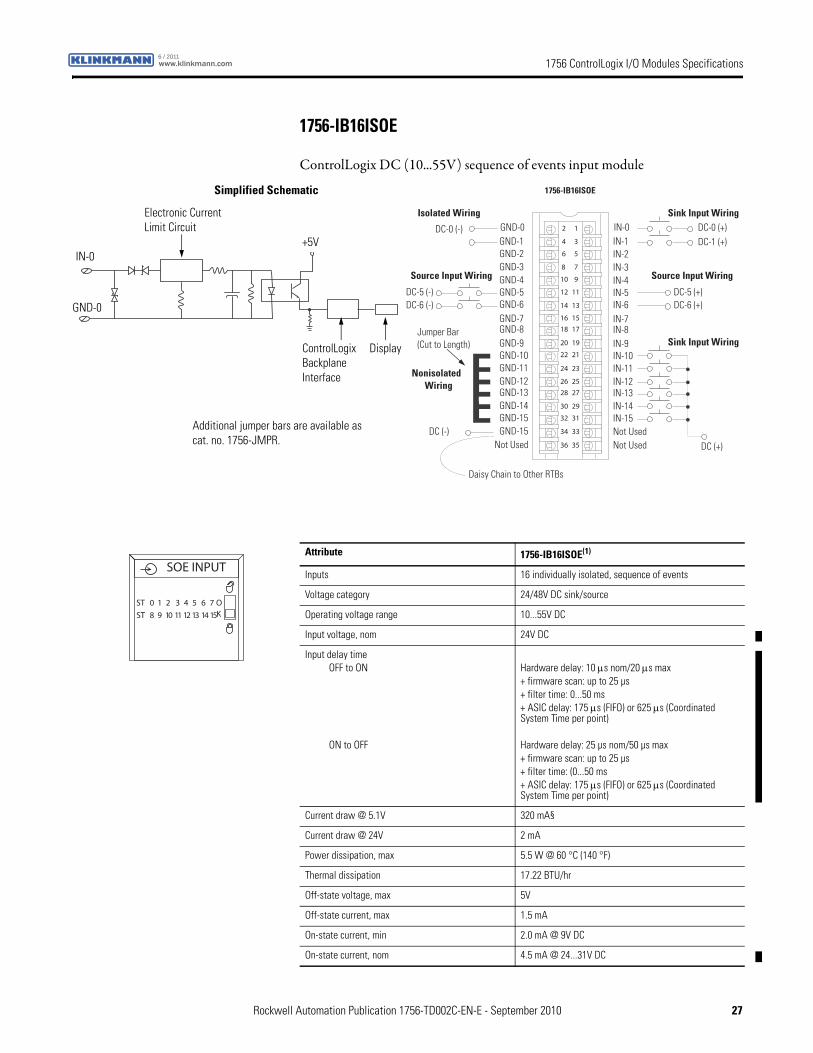
1756-IB16ISOE
ControlLogix DC (10...55V) sequence of events input module
12
34
56
78
910
1112
1314
1516
1718
1920
2122
2324
2526
2728
2930
3132
3334
3536
Nonisolated Wiring
Isolated Wiring
Daisy Chain to Other RTBs
DC (-)
Jumper Bar (Cut to Length)
)+( 6-CD)-( 6-CD
DC (+)
DC-0 (+)DC-1 (+)
DC-0 (-)
DC-5 (-)
IN-0IN-1IN-2IN-3
IN-8
IN-4IN-5IN-6IN-7
Not Used
IN-9IN-10IN-11IN-12IN-13IN-14IN-15Not Used
GND-0GND-1GND-2GND-3
GND-8
GND-4GND-5GND-6GND-7
Not Used
GND-9GND-10GND-11GND-12GND-13GND-14GND-15GND-15
DC-5 (+)
Sink Input Wiring
Source Input WiringSource Input Wiring
Sink Input Wiring
1756-IB16ISOE
ControlLogix Backplane Interface
Simplified Schematic
Display
GND-0
IN-0
Electronic Current Limit Circuit
+5V
Additional jumper bars are available as cat. no. 1756-JMPR.
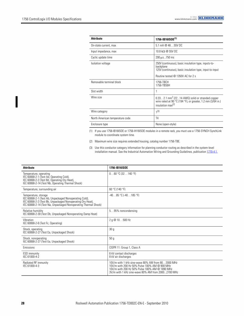
Attribute 1756-IB16ISOE(1)
Inputs 16 individually isolated, sequence of events
Voltage category 24/48V DC sink/source
Operating voltage range 10...55V DC
Input voltage, nom 24V DC
Input delay timeOFF to ON
ON to OFF
Hardware delay: 10 μs nom/20 μs max+ firmware scan: up to 25 µs+ filter time: 0...50 ms+ ASIC delay: 175 μs (FIFO) or 625 μs (Coordinated System Time per point)
Hardware delay: 25 µs nom/50 µs max+ firmware scan: up to 25 µs+ filter time: (0...50 ms+ ASIC delay: 175 μs (FIFO) or 625 μs (Coordinated System Time per point)
Current draw @ 5.1V 320 mA§
Current draw @ 24V 2 mA
Power dissipation, max 5.5 W @ 60 °C (140 °F)
Thermal dissipation 17.22 BTU/hr
Off-state voltage, max 5V
Off-state current, max 1.5 mA
On-state current, min 2.0 mA @ 9V DC
On-state current, nom 4.5 mA @ 24...31V DC
SOE INPUT
ST 0 1 2 3 4 5 6 7
ST 8 9 10 11 12 13 14 15
OK
Rockwell Automation Publication 1756-TD002C-EN-E - September 2010 27
1756 ControlLogix I/O Modules Specifications www.klinkmann.com6 / 2011
On-state current, max 5.1 mA @ 48…55V DC
Input impedance, max 10.8 kΩ @ 55V DC
Cyclic update time 200 μs...750 ms
Isolation voltage 250V (continuous), basic insulation type, inputs-to-backplane125V (continuous), basic insulation type, input-to-input
Routine tested @ 1350V AC for 2 s
Removable terminal block 1756-TBCH1756-TBS6H
Slot width 1
Wire size 0.33... 2.1 mm2 (22...14 AWG) solid or stranded copper wire rated at 90 °C (194 °F), or greater, 1.2 mm (3/64 in.) insulation max(2)
Wire category 1(3)
North American temperature code T4
Enclosure type None (open-style)
(1) If you use 1756-IB16ISOE or 1756-IH16ISOE modules in a remote rack, you must use a 1756-SYNCH SynchLink module to coordinate system time.
(2) Maximum wire size requires extended housing, catalog number 1756-TBE.
(3) Use this conductor category information for planning conductor routing as described in the system-level installation manual. See the Industrial Automation Wiring and Grounding Guidelines, publication 1770-4.1.
Attribute 1756-IB16ISOE(1)
Attribute 1756-IB16ISOE
Temperature, operatingIEC 60068-2-1 (Test Ad, Operating Cold),IEC 60068-2-2 (Test Bd, Operating Dry Heat),IEC 60068-2-14 (Test Nb, Operating Thermal Shock)
0…60 °C (32…140 °F)
Temperature, surrounding air 60 °C (140 °F)
Temperature, storageIEC 60068-2-1 (Test Ab, Unpackaged Nonoperating Cold),IEC 60068-2-2 (Test Bb, Unpackaged Nonoperating Dry Heat),IEC 60068-2-14 (Test Na, Unpackaged Nonoperating Thermal Shock)
-40…85 °C (-40…185 °F)
Relative humidityIEC 60068-2-30 (Test Db, Unpackaged Nonoperating Damp Heat)
5…95% noncondensing
VibrationIEC 60068-2-6 (Test Fc, Operating)
2 g @ 10…500 Hz
Shock, operatingIEC 60068-2-27 (Test Ea, Unpackaged Shock)
30 g
Shock, nonoperatingIEC 60068-2-27 (Test Ea, Unpackaged Shock)
50 g
Emissions CISPR 11: Group 1, Class A
ESD immunityIEC 61000-4-2
6 kV contact discharges8 kV air discharges
Radiated RF immunityIEC 61000-4-3
10V/m with 1 kHz sine-wave 80% AM from 80... 2000 MHz10V/m with 200 Hz 50% Pulse 100% AM @ 900 MHz10V/m with 200 Hz 50% Pulse 100% AM @ 1890 MHz3V/m with 1 kHz sine-wave 80% AM from 2000...2700 MHz
28 Rockwell Automation Publication 1756-TD002C-EN-E - September 2010
1756 ControlLogix I/O Modules Specificationswww.klinkmann.com6 / 2011
EFT/B immunityIEC 61000-4-4
±4 kV at 5 kHz on signal ports
Surge transient immunityIEC 61000-4-5
±1 kV line-line (DM) and ±2 kV line-earth (CM) on signal ports
Conducted RF immunityIEC 61000-4-6
10Vrms with 1 kHz sine-wave 80% AM from 150 kHz...80 MHz
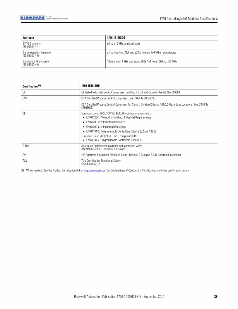
Attribute 1756-IB16ISOE
Certification(1) 1756-IB16ISOE
UL UL Listed Industrial Control Equipment, certified for US and Canada. See UL File E65584.
CSA CSA Certified Process Control Equipment. See CSA File LR54689C.
CSA Certified Process Control Equipment for Class I, Division 2 Group A,B,C,D Hazardous Locations. See CSA File LR69960C.
CE European Union 2004/108/IEC EMC Directive, compliant with:• EN 61326-1; Meas./Control/Lab., Industrial Requirements
• EN 61000-6-2; Industrial Immunity
• EN 61000-6-4; Industrial Emissions
• EN 61131-2; Programmable Controllers (Clause 8, Zone A & B)
European Union 2006/95/EC LVD, compliant with:• EN 61131-2; Programmable Controllers (Clause 11)
C-Tick Australian Radiocommunications Act, compliant with:AS/NZS CISPR 11; Industrial Emissions
FM FM Approved Equipment for use in Class I Division 2 Group A,B,C,D Hazardous Locations
TÜV TÜV Certified for Functional Safety:Capable of SIL 2
(1) When marked. See the Product Certification link at http://www.ab.com for Declarations of Conformity, Certificates, and other certification details.
Rockwell Automation Publication 1756-TD002C-EN-E - September 2010 29
1756 ControlLogix I/O Modules Specifications www.klinkmann.com6 / 2011
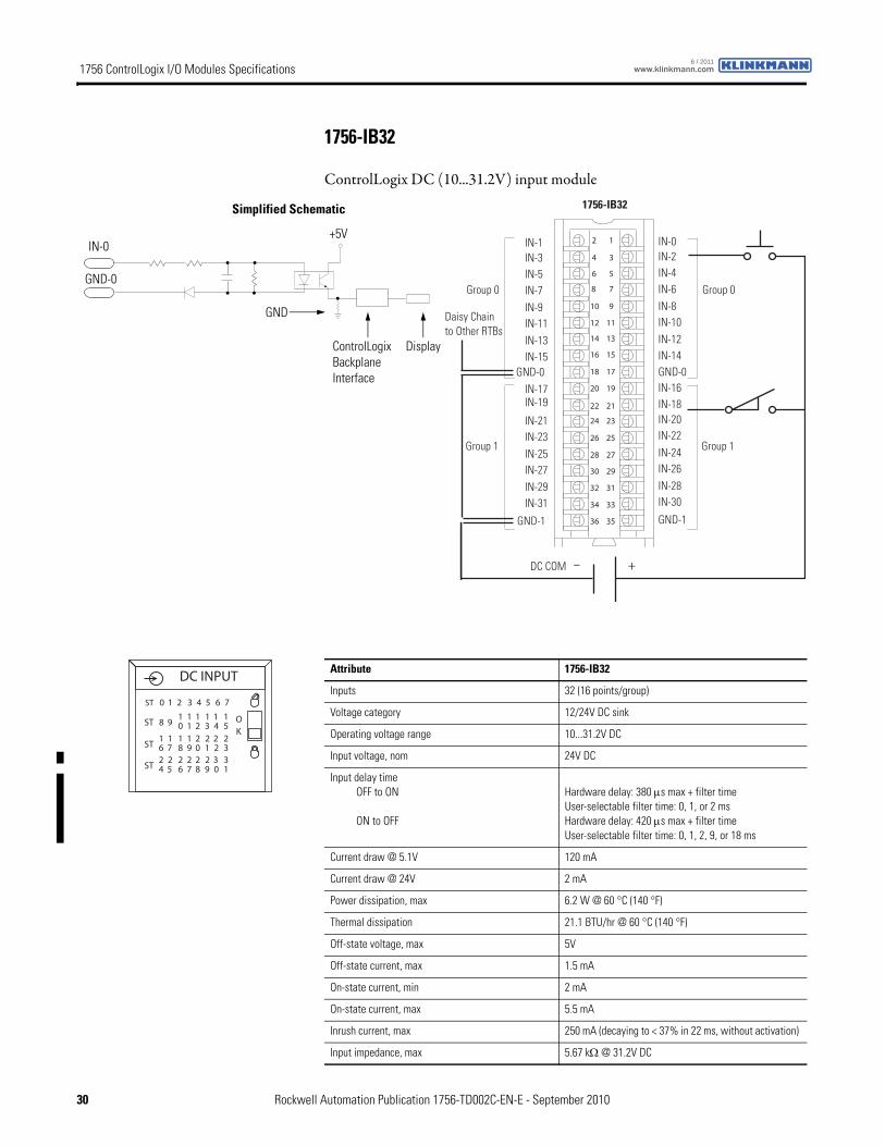
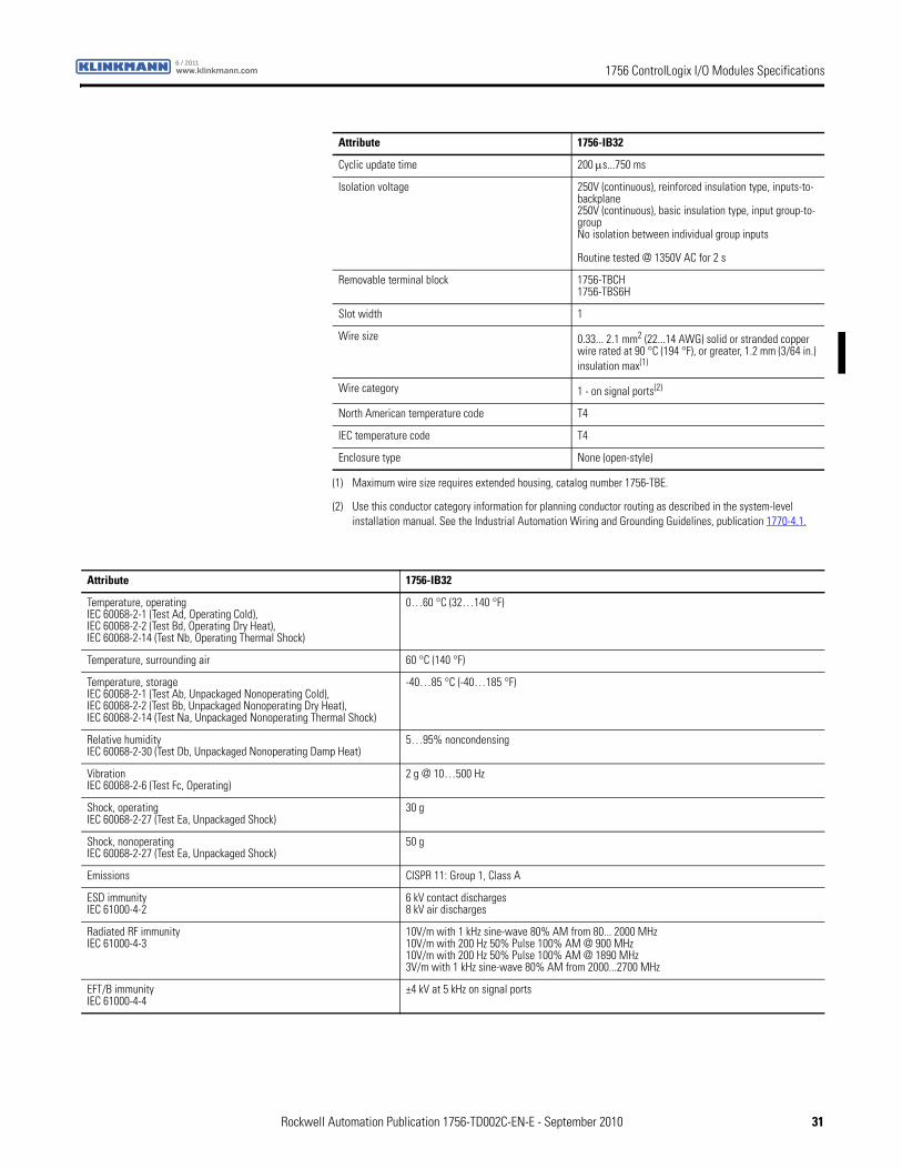
1756-IB32
ControlLogix DC (10...31.2V) input module
12
34
56
78
910
1112
1314
1516
1718
1920
2122
2324
2526
2728
2930
3132
3334
3536
+–
Daisy Chain to Other RTBs
DC COM
0 puorG0 puorG
1 puorG1 puorG
1756-IB32
IN-1IN-3IN-5IN-7
GND-0
IN-9IN-11IN-13IN-15
GND-1
IN-17IN-19
IN-21IN-23IN-25IN-27IN-29IN-31
IN-0IN-2IN-4IN-6
GND-0
IN-8IN-10IN-12IN-14
GND-1
IN-16IN-18IN-20IN-22IN-24IN-26IN-28IN-30
ControlLogix Backplane Interface
Simplified Schematic
Display
GND-0
GND
IN-0+5V
Attribute 1756-IB32
Inputs 32 (16 points/group)
Voltage category 12/24V DC sink
Operating voltage range 10...31.2V DC
Input voltage, nom 24V DC
Input delay timeOFF to ON
ON to OFF
Hardware delay: 380 μs max + filter timeUser-selectable filter time: 0, 1, or 2 msHardware delay: 420 μs max + filter timeUser-selectable filter time: 0, 1, 2, 9, or 18 ms
Current draw @ 5.1V 120 mA
Current draw @ 24V 2 mA
Power dissipation, max 6.2 W @ 60 °C (140 °F)
Thermal dissipation 21.1 BTU/hr @ 60 °C (140 °F)
Off-state voltage, max 5V
Off-state current, max 1.5 mA
On-state current, min 2 mA
On-state current, max 5.5 mA
Inrush current, max 250 mA (decaying to < 37% in 22 ms, without activation)
Input impedance, max 5.67 kΩ @ 31.2V DC
DC INPUT
OK
ST 0 1 2 3 4 5 6 7
ST 8 910 21 3 4 5
1 1 1 11
ST 6 718 09 1 2 3
1 2 2 221 1
ST 4 526 87 9 0 1
2 2 2 332 2
30 Rockwell Automation Publication 1756-TD002C-EN-E - September 2010
1756 ControlLogix I/O Modules Specificationswww.klinkmann.com6 / 2011
Cyclic update time 200 μs...750 ms
Isolation voltage 250V (continuous), reinforced insulation type, inputs-to-backplane250V (continuous), basic insulation type, input group-to-groupNo isolation between individual group inputs
Routine tested @ 1350V AC for 2 s
Removable terminal block 1756-TBCH1756-TBS6H
Slot width 1
Wire size 0.33... 2.1 mm2 (22...14 AWG) solid or stranded copper wire rated at 90 °C (194 °F), or greater, 1.2 mm (3/64 in.) insulation max(1)
Wire category 1 - on signal ports(2)
North American temperature code T4
IEC temperature code T4
Enclosure type None (open-style)
(1) Maximum wire size requires extended housing, catalog number 1756-TBE.
(2) Use this conductor category information for planning conductor routing as described in the system-level installation manual. See the Industrial Automation Wiring and Grounding Guidelines, publication 1770-4.1.
Attribute 1756-IB32
Attribute 1756-IB32
Temperature, operatingIEC 60068-2-1 (Test Ad, Operating Cold),IEC 60068-2-2 (Test Bd, Operating Dry Heat),IEC 60068-2-14 (Test Nb, Operating Thermal Shock)
0…60 °C (32…140 °F)
Temperature, surrounding air 60 °C (140 °F)
Temperature, storageIEC 60068-2-1 (Test Ab, Unpackaged Nonoperating Cold),IEC 60068-2-2 (Test Bb, Unpackaged Nonoperating Dry Heat),IEC 60068-2-14 (Test Na, Unpackaged Nonoperating Thermal Shock)
-40…85 °C (-40…185 °F)
Relative humidityIEC 60068-2-30 (Test Db, Unpackaged Nonoperating Damp Heat)
5…95% noncondensing
VibrationIEC 60068-2-6 (Test Fc, Operating)
2 g @ 10…500 Hz
Shock, operatingIEC 60068-2-27 (Test Ea, Unpackaged Shock)
30 g
Shock, nonoperatingIEC 60068-2-27 (Test Ea, Unpackaged Shock)
50 g
Emissions CISPR 11: Group 1, Class A
ESD immunityIEC 61000-4-2
6 kV contact discharges8 kV air discharges
Radiated RF immunityIEC 61000-4-3
10V/m with 1 kHz sine-wave 80% AM from 80... 2000 MHz10V/m with 200 Hz 50% Pulse 100% AM @ 900 MHz10V/m with 200 Hz 50% Pulse 100% AM @ 1890 MHz3V/m with 1 kHz sine-wave 80% AM from 2000...2700 MHz
EFT/B immunityIEC 61000-4-4
±4 kV at 5 kHz on signal ports
Rockwell Automation Publication 1756-TD002C-EN-E - September 2010 31
1756 ControlLogix I/O Modules Specifications www.klinkmann.com6 / 2011
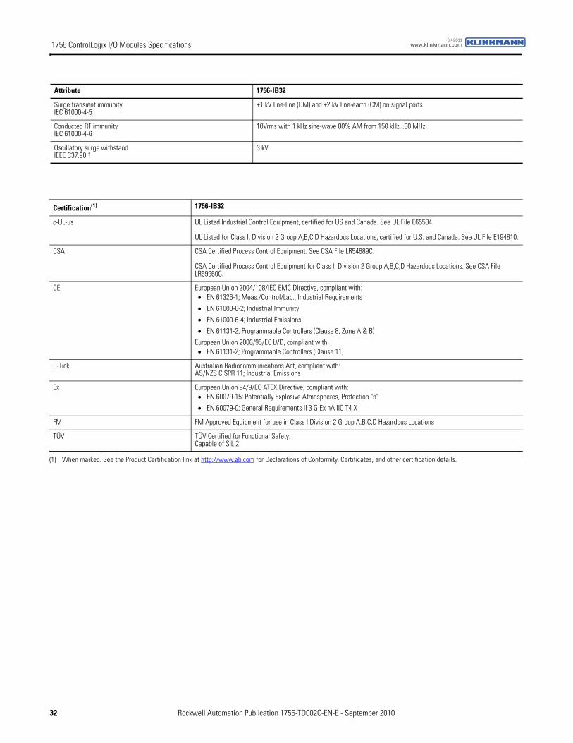
Surge transient immunityIEC 61000-4-5
±1 kV line-line (DM) and ±2 kV line-earth (CM) on signal ports
Conducted RF immunityIEC 61000-4-6
10Vrms with 1 kHz sine-wave 80% AM from 150 kHz...80 MHz
Oscillatory surge withstandIEEE C37.90.1
3 kV
Attribute 1756-IB32
Certification(1) 1756-IB32
c-UL-us UL Listed Industrial Control Equipment, certified for US and Canada. See UL File E65584.
UL Listed for Class I, Division 2 Group A,B,C,D Hazardous Locations, certified for U.S. and Canada. See UL File E194810.
CSA CSA Certified Process Control Equipment. See CSA File LR54689C.
CSA Certified Process Control Equipment for Class I, Division 2 Group A,B,C,D Hazardous Locations. See CSA File LR69960C.
CE European Union 2004/108/IEC EMC Directive, compliant with:• EN 61326-1; Meas./Control/Lab., Industrial Requirements
• EN 61000-6-2; Industrial Immunity
• EN 61000-6-4; Industrial Emissions
• EN 61131-2; Programmable Controllers (Clause 8, Zone A & B)
European Union 2006/95/EC LVD, compliant with:• EN 61131-2; Programmable Controllers (Clause 11)
C-Tick Australian Radiocommunications Act, compliant with:AS/NZS CISPR 11; Industrial Emissions
Ex European Union 94/9/EC ATEX Directive, compliant with:• EN 60079-15; Potentially Explosive Atmospheres, Protection "n"
• EN 60079-0; General Requirements II 3 G Ex nA IIC T4 X
FM FM Approved Equipment for use in Class I Division 2 Group A,B,C,D Hazardous Locations
TÜV TÜV Certified for Functional Safety:Capable of SIL 2
(1) When marked. See the Product Certification link at http://www.ab.com for Declarations of Conformity, Certificates, and other certification details.
32 Rockwell Automation Publication 1756-TD002C-EN-E - September 2010
1756 ControlLogix I/O Modules Specificationswww.klinkmann.com6 / 2011
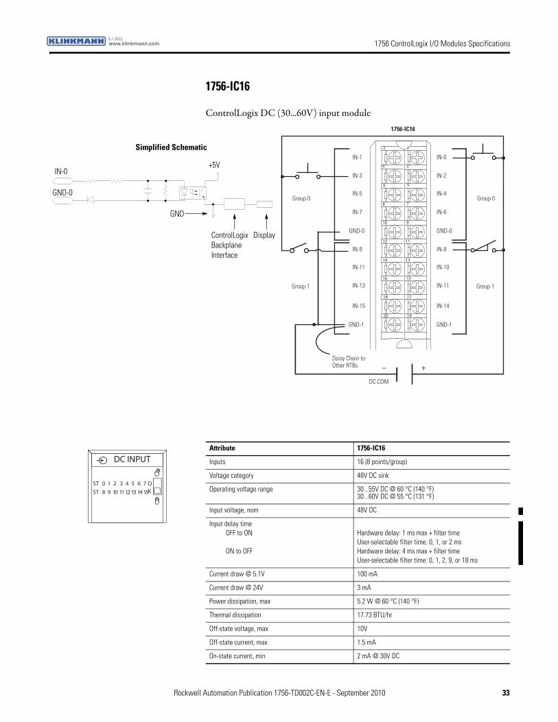
1756-IC16
ControlLogix DC (30...60V) input module
12
34
56
78
910
1112
1314
1516
1718
1920
+–Daisy Chain to Other RTBs
1756-IC16
Group 0Group 0
Group 1Group 1
IN-1
IN-3
IN-5
IN-7
GND-0
IN-9
IN-11
IN-13
IN-15
GND-1
IN-0
IN-2
IN-4
IN-6
GND-0
IN-8
IN-10
IN-11
IN-14
GND-1
DC COM
Simplified Schematic
GND-0
IN-0
ControlLogix Backplane Interface
Display
GND
+5V
Attribute 1756-IC16
Inputs 16 (8 points/group)
Voltage category 48V DC sink
Operating voltage range 30...55V DC @ 60 °C (140 °F)30...60V DC @ 55 °C (131 °F)
Input voltage, nom 48V DC
Input delay timeOFF to ON
ON to OFF
Hardware delay: 1 ms max + filter timeUser-selectable filter time: 0, 1, or 2 msHardware delay: 4 ms max + filter timeUser-selectable filter time: 0, 1, 2, 9, or 18 ms
Current draw @ 5.1V 100 mA
Current draw @ 24V 3 mA
Power dissipation, max 5.2 W @ 60 °C (140 °F)
Thermal dissipation 17.73 BTU/hr
Off-state voltage, max 10V
Off-state current, max 1.5 mA
On-state current, min 2 mA @ 30V DC
DC INPUT
ST 0 1 2 3 4 5 6 7
ST 8 9 10 11 12 13 14 15
OK
Rockwell Automation Publication 1756-TD002C-EN-E - September 2010 33
1756 ControlLogix I/O Modules Specifications www.klinkmann.com6 / 2011
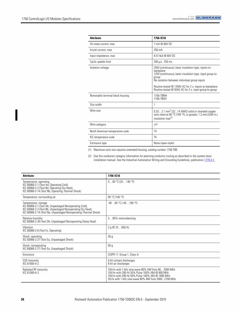
On-state current, max 7 mA @ 60V DC
Inrush current, max 250 mA
Input impedance, max 8.57 kΩ @ 60V DC
Cyclic update time 200 μs...750 ms
Isolation voltage 250V (continuous), basic insulation type, inputs-to-backplane125V (continuous), basic insulation type, input group-to-groupNo isolation between individual group inputs
Routine tested @ 1350V AC for 2 s, inputs-to-backplaneRoutine tested @ 924V AC for 2 s, input group-to-group
Removable terminal block housing 1756-TBNH1756-TBSH
Slot width 1
Wire size 0.33... 2.1 mm2 (22...14 AWG) solid or stranded copper wire rated at 90 °C (194 °F), or greater, 1.2 mm (3/64 in.) insulation max(1)
Wire category 1(2)
North American temperature code T4
IEC temperature code T4
Enclosure type None (open-style)
(1) Maximum wire size requires extended housing, catalog number 1756-TBE.
(2) Use this conductor category information for planning conductor routing as described in the system-level installation manual. See the Industrial Automation Wiring and Grounding Guidelines, publication 1770-4.1.
Attribute 1756-IC16
Attribute 1756-IC16
Temperature, operatingIEC 60068-2-1 (Test Ad, Operating Cold),IEC 60068-2-2 (Test Bd, Operating Dry Heat),IEC 60068-2-14 (Test Nb, Operating Thermal Shock)
0…60 °C (32…140 °F)
Temperature, surrounding air 60 °C (140 °F)
Temperature, storageIEC 60068-2-1 (Test Ab, Unpackaged Nonoperating Cold),IEC 60068-2-2 (Test Bb, Unpackaged Nonoperating Dry Heat),IEC 60068-2-14 (Test Na, Unpackaged Nonoperating Thermal Shock)
-40…85 °C (-40…185 °F)
Relative humidityIEC 60068-2-30 (Test Db, Unpackaged Nonoperating Damp Heat)
5…95% noncondensing
VibrationIEC 60068-2-6 (Test Fc, Operating)
2 g @ 10…500 Hz
Shock, operatingIEC 60068-2-27 (Test Ea, Unpackaged Shock)
30 g
Shock, nonoperatingIEC 60068-2-27 (Test Ea, Unpackaged Shock)
50 g
Emissions CISPR 11: Group 1, Class A
ESD immunityIEC 61000-4-2
6 kV contact discharges8 kV air discharges
Radiated RF immunityIEC 61000-4-3
10V/m with 1 kHz sine-wave 80% AM from 80... 2000 MHz10V/m with 200 Hz 50% Pulse 100% AM @ 900 MHz10V/m with 200 Hz 50% Pulse 100% AM @ 1890 MHz3V/m with 1 kHz sine-wave 80% AM from 2000...2700 MHz
34 Rockwell Automation Publication 1756-TD002C-EN-E - September 2010
1756 ControlLogix I/O Modules Specificationswww.klinkmann.com6 / 2011
EFT/B immunityIEC 61000-4-4
±4 kV at 5 kHz on signal ports
Surge transient immunityIEC 61000-4-5
±1 kV line-line (DM) and ± 2kV line-earth (CM) on signal ports
Conducted RF immunityIEC 61000-4-6
10Vrms with 1 kHz sine-wave 80% AM from 150 kHz...80 MHz
Oscillatory surge withstandIEEE C37.90.1
3 kV
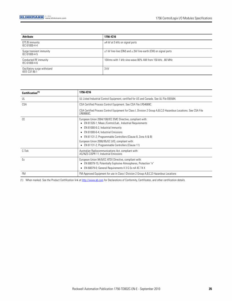
Attribute 1756-IC16
Certification(1) 1756-IC16
UL UL Listed Industrial Control Equipment, certified for US and Canada. See UL File E65584.
CSA CSA Certified Process Control Equipment. See CSA File LR54689C.
CSA Certified Process Control Equipment for Class I, Division 2 Group A,B,C,D Hazardous Locations. See CSA File LR69960C.
CE European Union 2004/108/IEC EMC Directive, compliant with:• EN 61326-1; Meas./Control/Lab., Industrial Requirements
• EN 61000-6-2; Industrial Immunity
• EN 61000-6-4; Industrial Emissions
• EN 61131-2; Programmable Controllers (Clause 8, Zone A & B)
European Union 2006/95/EC LVD, compliant with:• EN 61131-2; Programmable Controllers (Clause 11)
C-Tick Australian Radiocommunications Act, compliant with:AS/NZS CISPR 11; Industrial Emissions
Ex European Union 94/9/EC ATEX Directive, compliant with:• EN 60079-15; Potentially Explosive Atmospheres, Protection "n"
• EN 60079-0; General Requirements II 3 G Ex nA IIC T4 X
FM FM Approved Equipment for use in Class I Division 2 Group A,B,C,D Hazardous Locations
(1) When marked. See the Product Certification link at http://www.ab.com for Declarations of Conformity, Certificates, and other certification details.
Rockwell Automation Publication 1756-TD002C-EN-E - September 2010 35
1756 ControlLogix I/O Modules Specifications www.klinkmann.com6 / 2011
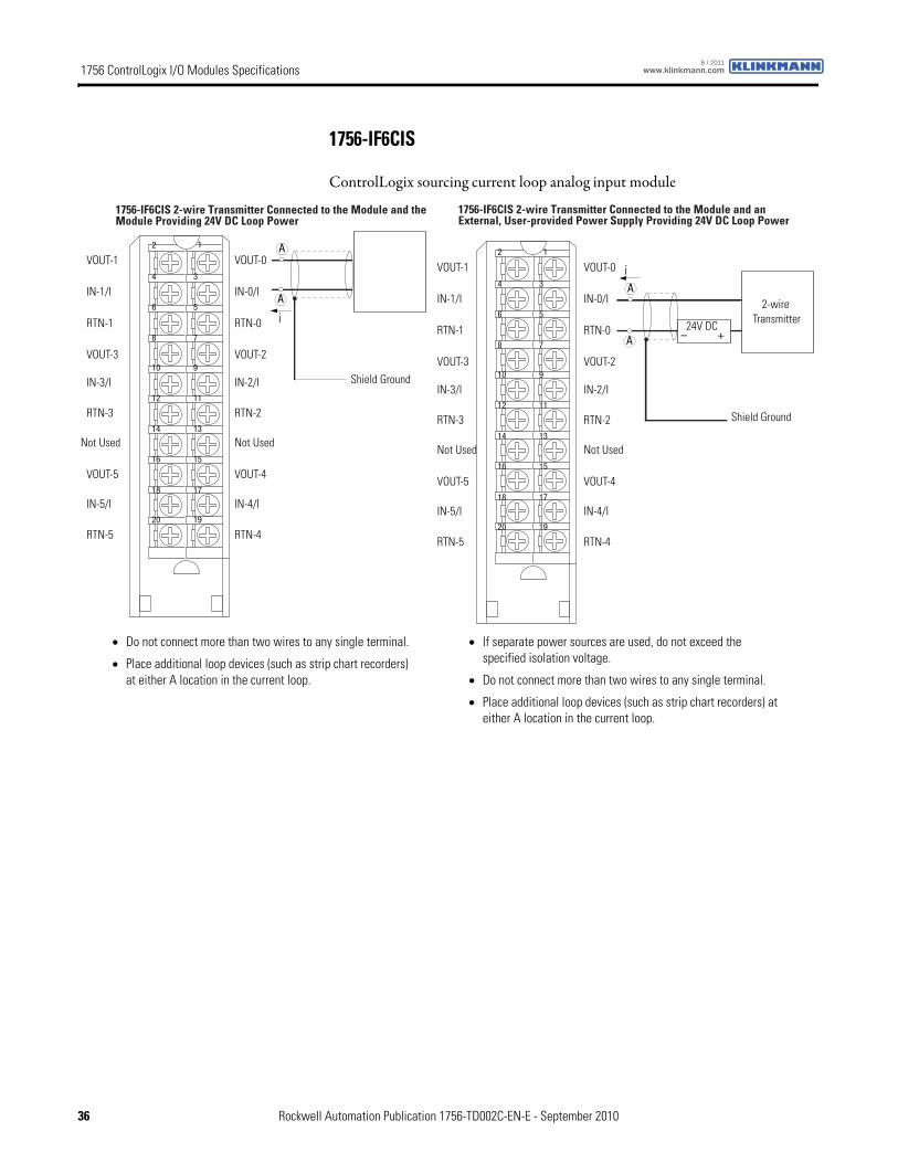
1756-IF6CIS
ControlLogix sourcing current loop analog input module
12
34
56
78
910
1112
1314
1516
1718
1920
VOUT-1
IN-1/I
RTN-1
VOUT-3
IN-3/I
RTN-3
Not Used
VOUT-5
IN-5/I
RTN-5
VOUT-0
IN-0/I
RTN-0
VOUT-2
IN-2/I
RTN-2
Not Used
VOUT-4
IN-4/I
RTN-4
2-wireTransmitter
Shield Ground
1756-IF6CIS 2-wire Transmitter Connected to the Module and anExternal, User-provided Power Supply Providing 24V DC Loop Power
+–
iA
A24V DC
12
34
56
78
910
1112
1314
1516
1718
1920
VOUT-1
IN-1/I
RTN-1
VOUT-3
IN-3/I
RTN-3
Not Used
VOUT-5
IN-5/I
RTN-5
VOUT-0
IN-0/I
RTN-0
VOUT-2
IN-2/I
RTN-2
Not Used
VOUT-4
IN-4/I
RTN-4
Shield Ground
1756-IF6CIS 2-wire Transmitter Connected to the Module and theModule Providing 24V DC Loop Power
A
iA
• Do not connect more than two wires to any single terminal.
• Place additional loop devices (such as strip chart recorders) at either A location in the current loop.
• If separate power sources are used, do not exceed the specified isolation voltage.
• Do not connect more than two wires to any single terminal.
• Place additional loop devices (such as strip chart recorders) at either A location in the current loop.
36 Rockwell Automation Publication 1756-TD002C-EN-E - September 2010
1756 ControlLogix I/O Modules Specificationswww.klinkmann.com6 / 2011
12
34
56
78
910
1112
1314
1516
1718
1920
VOUT-1
IN-1/I
RTN-1
VOUT-3
IN-3/I
RTN-3
Not Used
VOUT-5
IN-5/I
RTN-5
VOUT-0
IN-0/I
RTN-0
VOUT-2
IN-2/I
RTN-2
Not Used
VOUT-4
IN-4/I
RTN-4
4-wireTransmitter
Shield Ground
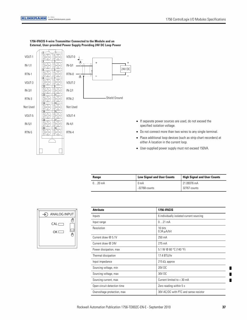
1756-IF6CIS 4-wire Transmitter Connected to the Module and anExternal, User-provided Power Supply Providing 24V DC Loop Power
+
–
+
–
iA
A
24V DC
• If separate power sources are used, do not exceed the specified isolation voltage.
• Do not connect more than two wires to any single terminal.
• Place additional loop devices (such as strip chart recorders) at either A location in the current loop.
• User-supplied power supply must not exceed 150VA.
Range Low Signal and User Counts High Signal and User Counts
0…20 mA 0 mA
-32768 counts
21.09376 mA
32767 counts
Attribute 1756-IF6CIS
Inputs 6 individually isolated current sourcing
Input range 0…21 mA
Resolution 16 bits0.34 μA/bit
Current draw @ 5.1V 250 mA
Current draw @ 24V 275 mA
Power dissipation, max 5.1 W @ 60 °C (140 °F)
Thermal dissipation 17.4 BTU/hr
Input impedance 215 Ω, approx
Sourcing voltage, min 20V DC
Sourcing voltage, max 30V DC
Sourcing current, max Current limited to < 30 mA
Open circuit detection time Zero reading within 5 s
Overvoltage protection, max 30V AC/DC with PTC and sense resistor
ANALOG INPUT
CAL
OK
Rockwell Automation Publication 1756-TD002C-EN-E - September 2010 37
1756 ControlLogix I/O Modules Specifications www.klinkmann.com6 / 2011
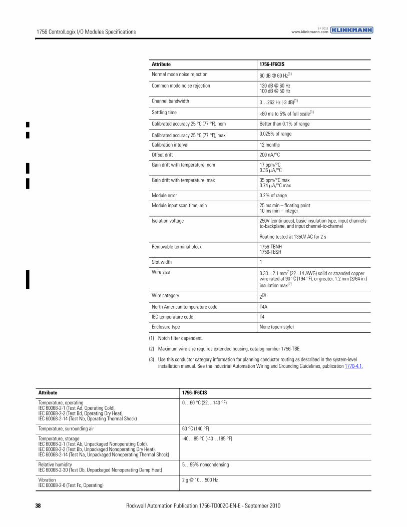
Normal mode noise rejection 60 dB @ 60 Hz(1)
Common mode noise rejection 120 dB @ 60 Hz100 dB @ 50 Hz
Channel bandwidth 3…262 Hz (-3 dB)(1)
Settling time <80 ms to 5% of full scale(1)
Calibrated accuracy 25 °C (77 °F), nom Better than 0.1% of range
Calibrated accuracy 25 °C (77 °F), max 0.025% of range
Calibration interval 12 months
Offset drift 200 nA/°C
Gain drift with temperature, nom 17 ppm/°C0.36 μA/°C
Gain drift with temperature, max 35 ppm/°C max0.74 μA/°C max
Module error 0.2% of range
Module input scan time, min 25 ms min – floating point10 ms min – integer
Isolation voltage 250V (continuous), basic insulation type, input channels-to-backplane, and input channel-to-channel
Routine tested at 1350V AC for 2 s
Removable terminal block 1756-TBNH1756-TBSH
Slot width 1
Wire size 0.33... 2.1 mm2 (22...14 AWG) solid or stranded copper wire rated at 90 °C (194 °F), or greater, 1.2 mm (3/64 in.) insulation max(2)
Wire category 2(3)
North American temperature code T4A
IEC temperature code T4
Enclosure type None (open-style)
(1) Notch filter dependent.
(2) Maximum wire size requires extended housing, catalog number 1756-TBE.
(3) Use this conductor category information for planning conductor routing as described in the system-level installation manual. See the Industrial Automation Wiring and Grounding Guidelines, publication 1770-4.1.
Attribute 1756-IF6CIS
Attribute 1756-IF6CIS
Temperature, operatingIEC 60068-2-1 (Test Ad, Operating Cold),IEC 60068-2-2 (Test Bd, Operating Dry Heat),IEC 60068-2-14 (Test Nb, Operating Thermal Shock)
0…60 °C (32…140 °F)
Temperature, surrounding air 60 °C (140 °F)
Temperature, storageIEC 60068-2-1 (Test Ab, Unpackaged Nonoperating Cold),IEC 60068-2-2 (Test Bb, Unpackaged Nonoperating Dry Heat),IEC 60068-2-14 (Test Na, Unpackaged Nonoperating Thermal Shock)
-40…85 °C (-40…185 °F)
Relative humidityIEC 60068-2-30 (Test Db, Unpackaged Nonoperating Damp Heat)
5…95% noncondensing
VibrationIEC 60068-2-6 (Test Fc, Operating)
2 g @ 10…500 Hz
38 Rockwell Automation Publication 1756-TD002C-EN-E - September 2010
1756 ControlLogix I/O Modules Specificationswww.klinkmann.com6 / 2011
Shock, operatingIEC 60068-2-27 (Test Ea, Unpackaged Shock)
30 g
Shock, nonoperatingIEC 60068-2-27 (Test Ea, Unpackaged Shock)
50 g
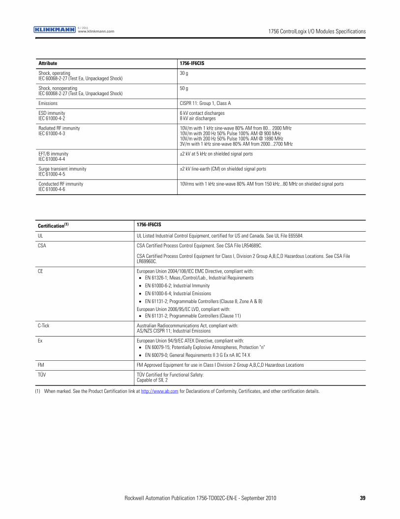
Emissions CISPR 11: Group 1, Class A
ESD immunityIEC 61000-4-2
6 kV contact discharges8 kV air discharges
Radiated RF immunityIEC 61000-4-3
10V/m with 1 kHz sine-wave 80% AM from 80... 2000 MHz10V/m with 200 Hz 50% Pulse 100% AM @ 900 MHz10V/m with 200 Hz 50% Pulse 100% AM @ 1890 MHz3V/m with 1 kHz sine-wave 80% AM from 2000...2700 MHz
EFT/B immunityIEC 61000-4-4
±2 kV at 5 kHz on shielded signal ports
Surge transient immunityIEC 61000-4-5
±2 kV line-earth (CM) on shielded signal ports
Conducted RF immunityIEC 61000-4-6
10Vrms with 1 kHz sine-wave 80% AM from 150 kHz...80 MHz on shielded signal ports
Attribute 1756-IF6CIS
Certification(1) 1756-IF6CIS
UL UL Listed Industrial Control Equipment, certified for US and Canada. See UL File E65584.
CSA CSA Certified Process Control Equipment. See CSA File LR54689C.
CSA Certified Process Control Equipment for Class I, Division 2 Group A,B,C,D Hazardous Locations. See CSA File LR69960C.
CE European Union 2004/108/IEC EMC Directive, compliant with:• EN 61326-1; Meas./Control/Lab., Industrial Requirements
• EN 61000-6-2; Industrial Immunity
• EN 61000-6-4; Industrial Emissions
• EN 61131-2; Programmable Controllers (Clause 8, Zone A & B)
European Union 2006/95/EC LVD, compliant with:• EN 61131-2; Programmable Controllers (Clause 11)
C-Tick Australian Radiocommunications Act, compliant with:AS/NZS CISPR 11; Industrial Emissions
Ex European Union 94/9/EC ATEX Directive, compliant with:• EN 60079-15; Potentially Explosive Atmospheres, Protection "n"
• EN 60079-0; General Requirements II 3 G Ex nA IIC T4 X
FM FM Approved Equipment for use in Class I Division 2 Group A,B,C,D Hazardous Locations
TÜV TÜV Certified for Functional Safety:Capable of SIL 2
(1) When marked. See the Product Certification link at http://www.ab.com for Declarations of Conformity, Certificates, and other certification details.
Rockwell Automation Publication 1756-TD002C-EN-E - September 2010 39
1756 ControlLogix I/O Modules Specifications www.klinkmann.com6 / 2011
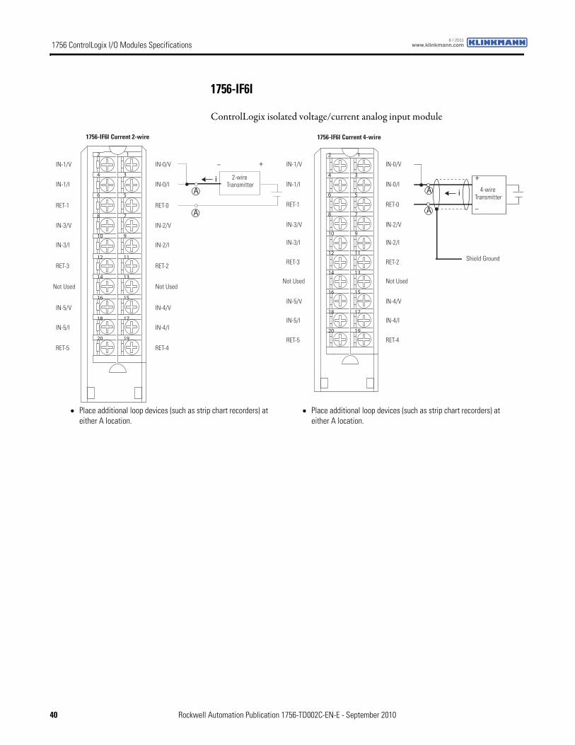
1756-IF6I
ControlLogix isolated voltage/current analog input module
12
34
56
78
910
1112
1314
1516
1718
1920
+–
iA
A
2-wire Transmitter
IN-1/V
IN-1/I
RET-1
IN-3/V
IN-3/I
RET-3
Not Used
IN-5/V
IN-5/I
RET-5
IN-0/V
IN-0/I
RET-0
IN-2/V
IN-2/I
RET-2
Not Used
IN-4/V
IN-4/I
RET-4
1756-IF6I Current 2-wire
+
–
12
34
56
78
910
1112
1314
1516
1718
1920
iA
A
IN-1/V
IN-1/I
RET-1
IN-3/V
IN-3/I
RET-3
Not Used
IN-5/V
IN-5/I
RET-5
IN-0/V
IN-0/I
RET-0
IN-2/V
IN-2/I
RET-2
Not Used
IN-4/V
IN-4/I
RET-4
Shield Ground
4-wire Transmitter
1756-IF6I Current 4-wire
• Place additional loop devices (such as strip chart recorders) at either A location.
• Place additional loop devices (such as strip chart recorders) at either A location.
40 Rockwell Automation Publication 1756-TD002C-EN-E - September 2010
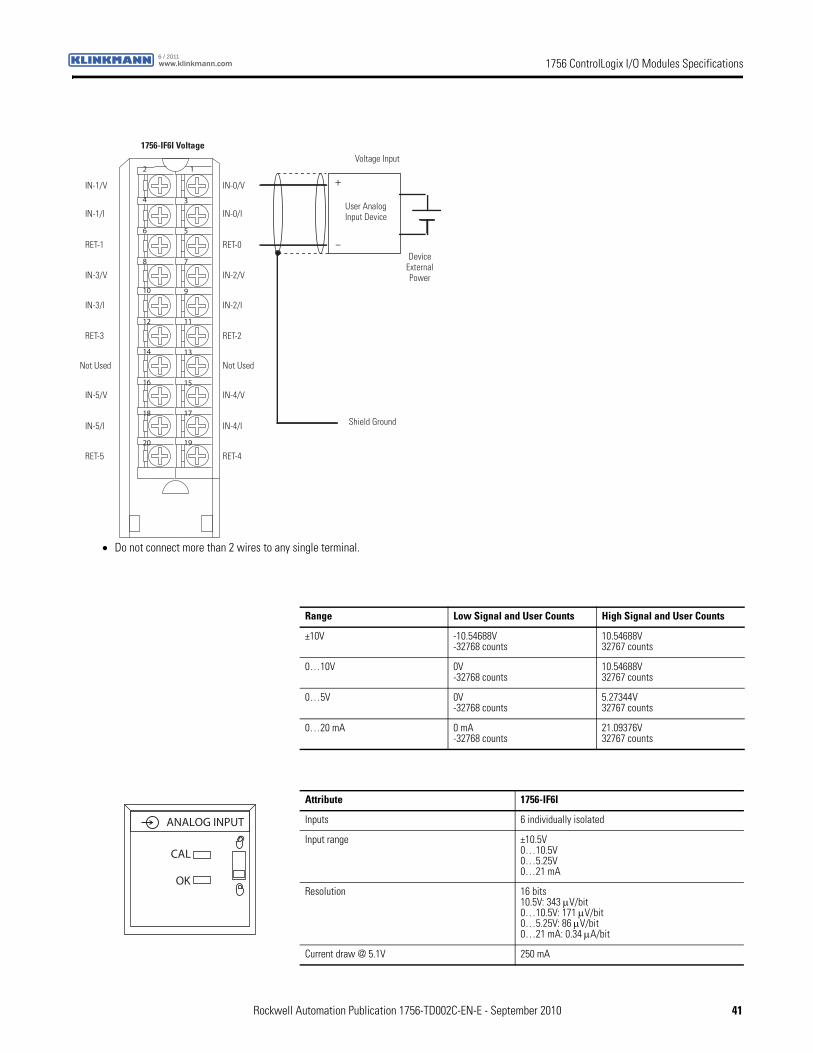
1756 ControlLogix I/O Modules Specificationswww.klinkmann.com6 / 2011
+
–
12
34
56
78
910
1112
1314
1516
1718
1920
Device External Power
1756-IF6I VoltageVoltage Input
Shield Ground
User Analog Input Device
IN-1/V
IN-1/I
RET-1
IN-3/V
IN-3/I
RET-3
Not Used
IN-5/V
IN-5/I
RET-5
IN-0/V
IN-0/I
RET-0
IN-2/V
IN-2/I
RET-2
Not Used
IN-4/V
IN-4/I
RET-4
• Do not connect more than 2 wires to any single terminal.
Range Low Signal and User Counts High Signal and User Counts
±10V -10.54688V-32768 counts
10.54688V32767 counts
0…10V 0V-32768 counts
10.54688V32767 counts
0…5V 0V-32768 counts
5.27344V32767 counts
0…20 mA 0 mA-32768 counts
21.09376V32767 counts
Attribute 1756-IF6I
Inputs 6 individually isolated
Input range ±10.5V0…10.5V0…5.25V0…21 mA
Resolution 16 bits10.5V: 343 μV/bit0…10.5V: 171 μV/bit0…5.25V: 86 μV/bit0…21 mA: 0.34 μA/bit
Current draw @ 5.1V 250 mA
ANALOG INPUT
CAL
OK
Rockwell Automation Publication 1756-TD002C-EN-E - September 2010 41
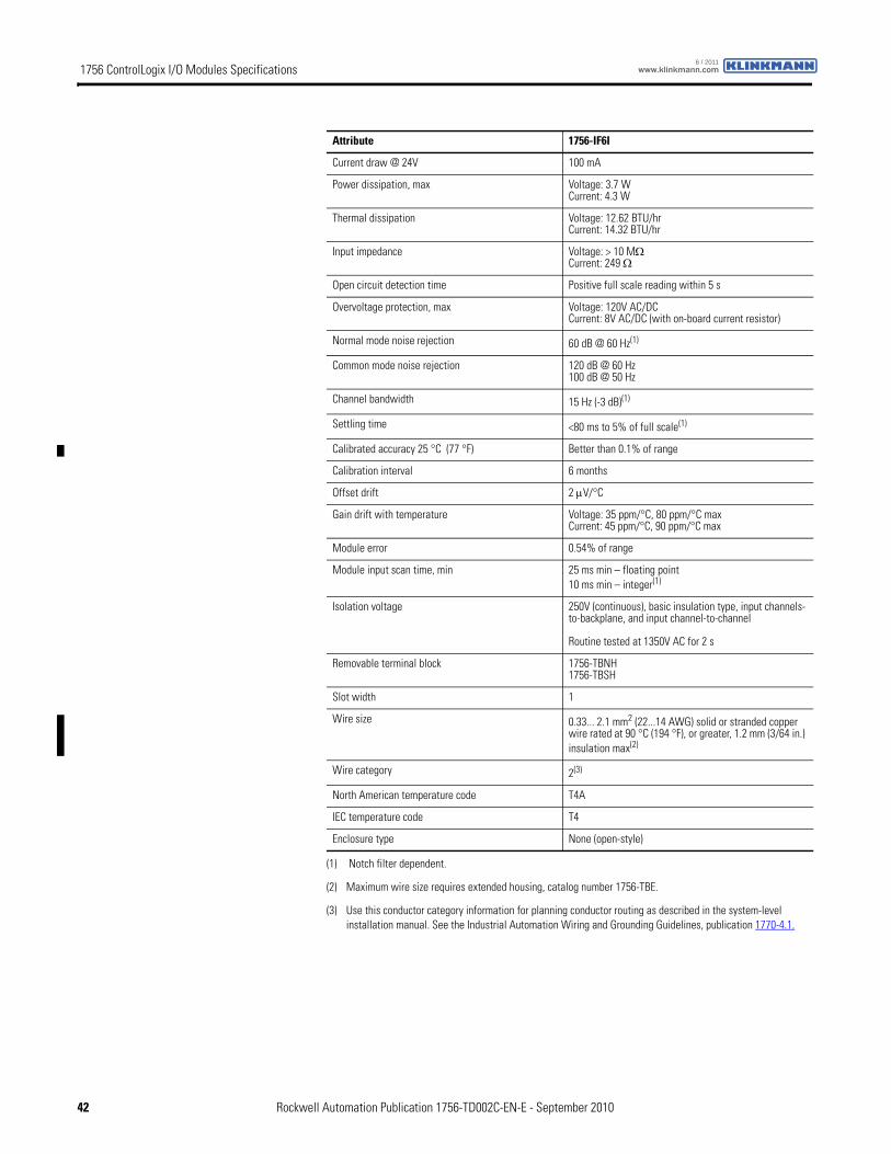
1756 ControlLogix I/O Modules Specifications www.klinkmann.com6 / 2011
Current draw @ 24V 100 mA
Power dissipation, max Voltage: 3.7 WCurrent: 4.3 W
Thermal dissipation Voltage: 12.62 BTU/hrCurrent: 14.32 BTU/hr
Input impedance Voltage: > 10 MΩCurrent: 249 Ω
Open circuit detection time Positive full scale reading within 5 s
Overvoltage protection, max Voltage: 120V AC/DCCurrent: 8V AC/DC (with on-board current resistor)
Normal mode noise rejection 60 dB @ 60 Hz(1)
Common mode noise rejection 120 dB @ 60 Hz100 dB @ 50 Hz
Channel bandwidth 15 Hz (-3 dB)(1)
Settling time <80 ms to 5% of full scale(1)
Calibrated accuracy 25 °C (77 °F) Better than 0.1% of range
Calibration interval 6 months
Offset drift 2 μV/°C
Gain drift with temperature Voltage: 35 ppm/°C, 80 ppm/°C maxCurrent: 45 ppm/°C, 90 ppm/°C max
Module error 0.54% of range
Module input scan time, min 25 ms min – floating point10 ms min – integer(1)
Isolation voltage 250V (continuous), basic insulation type, input channels-to-backplane, and input channel-to-channel
Routine tested at 1350V AC for 2 s
Removable terminal block 1756-TBNH1756-TBSH
Slot width 1
Wire size 0.33... 2.1 mm2 (22...14 AWG) solid or stranded copper wire rated at 90 °C (194 °F), or greater, 1.2 mm (3/64 in.) insulation max(2)
Wire category 2(3)
North American temperature code T4A
IEC temperature code T4
Enclosure type None (open-style)
(1) Notch filter dependent.
(2) Maximum wire size requires extended housing, catalog number 1756-TBE.
(3) Use this conductor category information for planning conductor routing as described in the system-level installation manual. See the Industrial Automation Wiring and Grounding Guidelines, publication 1770-4.1.
Attribute 1756-IF6I
42 Rockwell Automation Publication 1756-TD002C-EN-E - September 2010

1756 ControlLogix I/O Modules Specificationswww.klinkmann.com6 / 2011
Attribute 1756-IF6I
Temperature, operatingIEC 60068-2-1 (Test Ad, Operating Cold),IEC 60068-2-2 (Test Bd, Operating Dry Heat),IEC 60068-2-14 (Test Nb, Operating Thermal Shock)
0…60 °C (32…140 °F)
Temperature, surrounding air 60 °C (140 °F)
Temperature, storageIEC 60068-2-1 (Test Ab, Unpackaged Nonoperating Cold),IEC 60068-2-2 (Test Bb, Unpackaged Nonoperating Dry Heat),IEC 60068-2-14 (Test Na, Unpackaged Nonoperating Thermal Shock)
-40…85 °C (-40…185 °F)
Relative humidityIEC 60068-2-30 (Test Db, Unpackaged Nonoperating Damp Heat)
5…95% noncondensing
VibrationIEC 60068-2-6 (Test Fc, Operating)
2 g @ 10…500 Hz
Shock, operatingIEC 60068-2-27 (Test Ea, Unpackaged Shock)
30 g
Shock, nonoperatingIEC 60068-2-27 (Test Ea, Unpackaged Shock)
50 g
Emissions CISPR 11: Group 1, Class A
ESD immunityIEC 61000-4-2
6 kV contact discharges8 kV air discharges
Radiated RF immunityIEC 61000-4-3
10V/m with 1 kHz sine-wave 80% AM from 80... 2000 MHz10V/m with 200 Hz 50% Pulse 100% AM @ 900 MHz10V/m with 200 Hz 50% Pulse 100% AM @ 1890 MHz3V/m with 1 kHz sine-wave 80% AM from 2000...2700 MHz
EFT/B immunityIEC 61000-4-4
±2 kV at 5 kHz on shielded signal ports
Surge transient immunityIEC 61000-4-5
±2 kV line-earth (CM) on shielded signal ports
Conducted RF immunityIEC 61000-4-6
10Vrms with 1 kHz sine-wave 80% AM from 150 kHz...80 MHz on shielded signal ports
Certification(1) 1756-IF6I
UL UL Listed Industrial Control Equipment, certified for US and Canada. See UL File E65584.
CSA CSA Certified Process Control Equipment. See CSA File LR54689C.
CSA Certified Process Control Equipment for Class I, Division 2 Group A,B,C,D Hazardous Locations. See CSA File LR69960C.
CE European Union 2004/108/IEC EMC Directive, compliant with:• EN 61326-1; Meas./Control/Lab., Industrial Requirements
• EN 61000-6-2; Industrial Immunity
• EN 61000-6-4; Industrial Emissions
• EN 61131-2; Programmable Controllers (Clause 8, Zone A & B)
European Union 2006/95/EC LVD, compliant with:• EN 61131-2; Programmable Controllers (Clause 11)
C-Tick Australian Radiocommunications Act, compliant with:AS/NZS CISPR 11; Industrial Emissions
Ex European Union 94/9/EC ATEX Directive, compliant with:• EN 60079-15; Potentially Explosive Atmospheres, Protection "n"
• EN 60079-0; General Requirements II 3 G Ex nA IIC T4 X
FM FM Approved Equipment for use in Class I Division 2 Group A,B,C,D Hazardous Locations
TÜV TÜV Certified for Functional Safety:Capable of SIL 2
(1) When marked. See the Product Certification link at http://www.ab.com for Declarations of Conformity, Certificates, and other certification details.
Rockwell Automation Publication 1756-TD002C-EN-E - September 2010 43
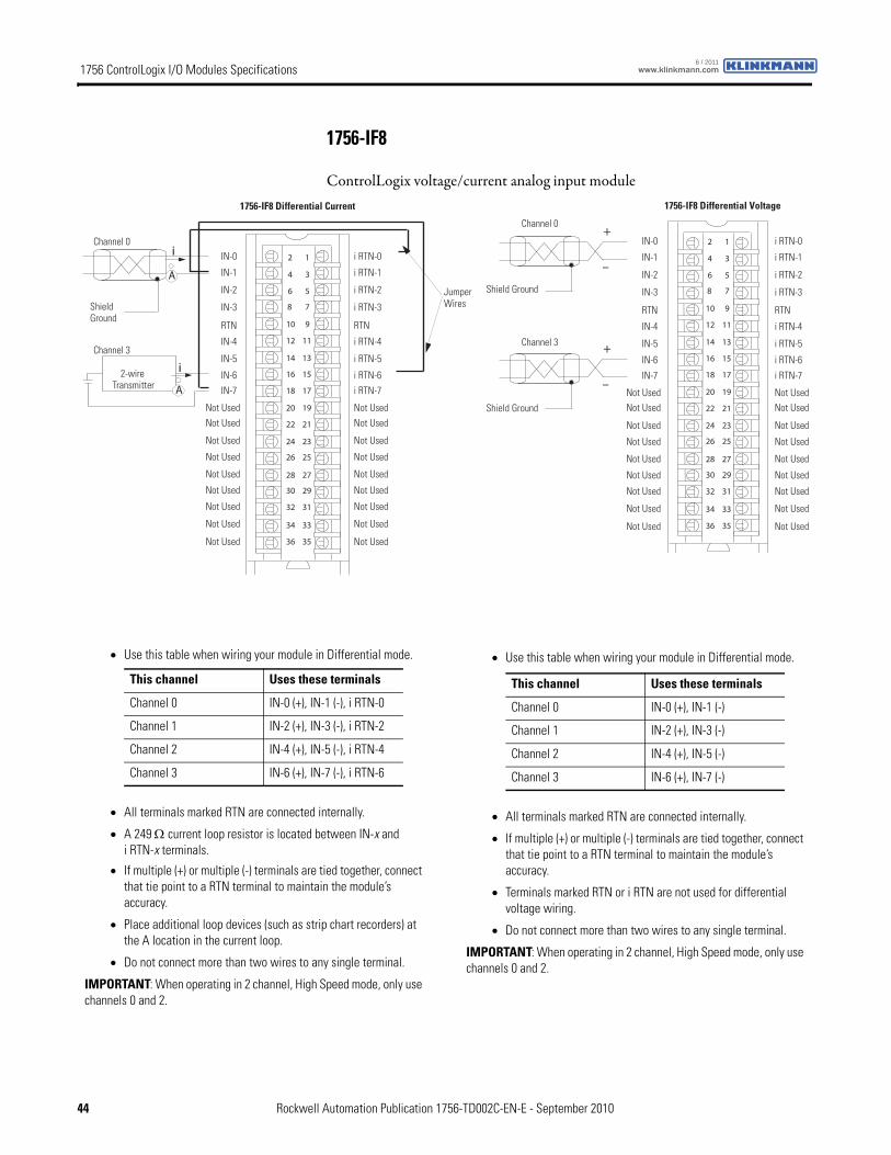
1756 ControlLogix I/O Modules Specifications www.klinkmann.com6 / 2011
1756-IF8
ControlLogix voltage/current analog input module
2
4
6
8
10
12
14
16
18
20
22
24
26
28
30
32
34
36
i
i
1756-IF8 Differential Current
A
A
Shield Ground
Channel 0
Channel 3
Jumper Wires
2-wire Transmitter
IN-0
IN-1
IN-2
IN-3
IN-7
RTN
IN-4
IN-5
IN-6
Not Used
Not UsedNot Used
Not Used
Not Used
Not Used
Not Used
Not Used
Not Used
1
3
5
7
9
11
13
15
17
19
21
23
25
27
29
31
33
35
i RTN-0
i RTN-1
i RTN-2
i RTN-3
i RTN-7
RTN
i RTN-4
i RTN-5
i RTN-6
Not Used
Not UsedNot Used
Not Used
Not Used
Not Used
Not Used
Not Used
Not Used
12
34
56
78
910
1112
1314
1516
1718
1920
2122
2324
2526
2728
2930
3132
3334
3536
+
–
+
–
1756-IF8 Differential Voltage
Shield Ground
Channel 0
Channel 3
IN-0
IN-1
IN-2
IN-3
IN-7
RTN
IN-4
IN-5
IN-6
Not Used
Not UsedNot Used
Not Used
Not Used
Not Used
Not Used
Not Used
Not Used
i RTN-0
i RTN-1
i RTN-2
i RTN-3
i RTN-7
RTN
i RTN-4
i RTN-5
i RTN-6
Not Used
Not UsedNot Used
Not Used
Not Used
Not Used
Not Used
Not Used
Not Used
Shield Ground
• Use this table when wiring your module in Differential mode.
• All terminals marked RTN are connected internally.
• A 249 Ω current loop resistor is located between IN-x and i RTN-x terminals.
• If multiple (+) or multiple (-) terminals are tied together, connect that tie point to a RTN terminal to maintain the module’s accuracy.
• Place additional loop devices (such as strip chart recorders) at the A location in the current loop.
• Do not connect more than two wires to any single terminal.
IMPORTANT: When operating in 2 channel, High Speed mode, only use channels 0 and 2.
This channel Uses these terminals
Channel 0 IN-0 (+), IN-1 (-), i RTN-0
Channel 1 IN-2 (+), IN-3 (-), i RTN-2
Channel 2 IN-4 (+), IN-5 (-), i RTN-4
Channel 3 IN-6 (+), IN-7 (-), i RTN-6
• Use this table when wiring your module in Differential mode.
• All terminals marked RTN are connected internally.
• If multiple (+) or multiple (-) terminals are tied together, connect that tie point to a RTN terminal to maintain the module’s accuracy.
• Terminals marked RTN or i RTN are not used for differential voltage wiring.
• Do not connect more than two wires to any single terminal.
IMPORTANT: When operating in 2 channel, High Speed mode, only use channels 0 and 2.
This channel Uses these terminals
Channel 0 IN-0 (+), IN-1 (-)
Channel 1 IN-2 (+), IN-3 (-)
Channel 2 IN-4 (+), IN-5 (-)
Channel 3 IN-6 (+), IN-7 (-)
44 Rockwell Automation Publication 1756-TD002C-EN-E - September 2010
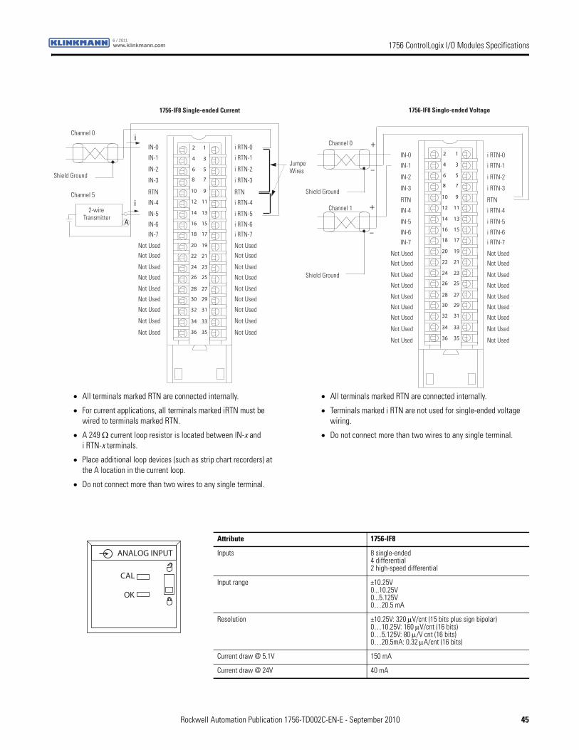
1756 ControlLogix I/O Modules Specificationswww.klinkmann.com6 / 2011
12
34
56
78
910
1112
1314
1516
1718
1920
2122
2324
2526
2728
2930
3132
3334
3536
i
i
A
Shield Ground
Channel 0
Channel 5
Jumper Wires
2-wire Transmitter
IN-0
IN-1
IN-2
IN-3
IN-7
RTN
IN-4
IN-5
IN-6
Not Used
Not UsedNot Used
Not Used
Not Used
Not Used
Not Used
Not Used
Not Used
i RTN-0
i RTN-1
i RTN-2
i RTN-3
i RTN-7
RTN
i RTN-4
i RTN-5
i RTN-6
Not Used
Not UsedNot Used
Not Used
Not Used
Not Used
Not Used
Not Used
Not Used
1756-IF8 Single-ended Current
12
34
56
78
910
1112
1314
1516
1718
1920
2122
2324
2526
2728
2930
3132
3334
3536
+
–
+
–
IN-0
IN-1
IN-2
IN-3
IN-7
RTN
IN-4
IN-5
IN-6
Not Used
Not UsedNot Used
Not Used
Not Used
Not Used
Not Used
Not Used
Not Used
i RTN-0
i RTN-1
i RTN-2
i RTN-3
i RTN-7
RTN
i RTN-4
i RTN-5
i RTN-6
Not Used
Not UsedNot Used
Not Used
Not Used
Not Used
Not Used
Not Used
Not Used
Shield Ground
Channel 0
Channel 1
Shield Ground
1756-IF8 Single-ended Voltage
• All terminals marked RTN are connected internally.
• For current applications, all terminals marked iRTN must be wired to terminals marked RTN.
• A 249 Ω current loop resistor is located between IN-x and i RTN-x terminals.
• Place additional loop devices (such as strip chart recorders) at the A location in the current loop.
• Do not connect more than two wires to any single terminal.
• All terminals marked RTN are connected internally.
• Terminals marked i RTN are not used for single-ended voltage wiring.
• Do not connect more than two wires to any single terminal.
Attribute 1756-IF8
Inputs 8 single-ended4 differential2 high-speed differential
Input range ±10.25V0...10.25V0...5.125V0…20.5 mA
Resolution ±10.25V: 320 μV/cnt (15 bits plus sign bipolar)0…10.25V: 160 μV/cnt (16 bits)0…5.125V: 80 μ/V cnt (16 bits)0…20.5mA: 0.32 μA/cnt (16 bits)
Current draw @ 5.1V 150 mA
Current draw @ 24V 40 mA
ANALOG INPUT
CAL
OK
Rockwell Automation Publication 1756-TD002C-EN-E - September 2010 45
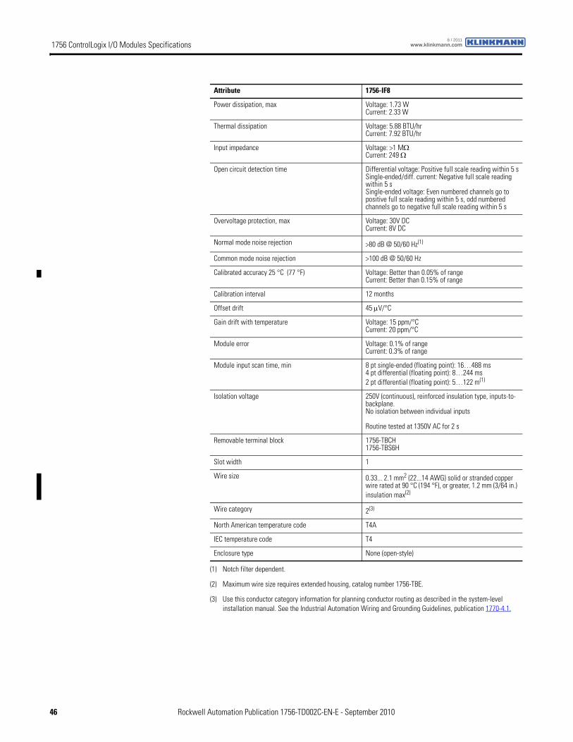
1756 ControlLogix I/O Modules Specifications www.klinkmann.com6 / 2011
Power dissipation, max Voltage: 1.73 WCurrent: 2.33 W
Thermal dissipation Voltage: 5.88 BTU/hrCurrent: 7.92 BTU/hr
Input impedance Voltage: >1 MΩCurrent: 249 Ω
Open circuit detection time Differential voltage: Positive full scale reading within 5 sSingle-ended/diff. current: Negative full scale reading within 5 sSingle-ended voltage: Even numbered channels go to positive full scale reading within 5 s, odd numbered channels go to negative full scale reading within 5 s
Overvoltage protection, max Voltage: 30V DCCurrent: 8V DC
Normal mode noise rejection >80 dB @ 50/60 Hz(1)
Common mode noise rejection >100 dB @ 50/60 Hz
Calibrated accuracy 25 °C (77 °F) Voltage: Better than 0.05% of rangeCurrent: Better than 0.15% of range
Calibration interval 12 months
Offset drift 45 μV/°C
Gain drift with temperature Voltage: 15 ppm/°CCurrent: 20 ppm/°C
Module error Voltage: 0.1% of rangeCurrent: 0.3% of range
Module input scan time, min 8 pt single-ended (floating point): 16…488 ms4 pt differential (floating point): 8…244 ms2 pt differential (floating point): 5…122 m(1)
Isolation voltage 250V (continuous), reinforced insulation type, inputs-to-backplane.No isolation between individual inputs
Routine tested at 1350V AC for 2 s
Removable terminal block 1756-TBCH1756-TBS6H
Slot width 1
Wire size 0.33... 2.1 mm2 (22...14 AWG) solid or stranded copper wire rated at 90 °C (194 °F), or greater, 1.2 mm (3/64 in.) insulation max(2)
Wire category 2(3)
North American temperature code T4A
IEC temperature code T4
Enclosure type None (open-style)
(1) Notch filter dependent.
(2) Maximum wire size requires extended housing, catalog number 1756-TBE.
(3) Use this conductor category information for planning conductor routing as described in the system-level installation manual. See the Industrial Automation Wiring and Grounding Guidelines, publication 1770-4.1.
Attribute 1756-IF8
46 Rockwell Automation Publication 1756-TD002C-EN-E - September 2010

1756 ControlLogix I/O Modules Specificationswww.klinkmann.com6 / 2011
Attribute 1756-IF8
Temperature, operatingIEC 60068-2-1 (Test Ad, Operating Cold),IEC 60068-2-2 (Test Bd, Operating Dry Heat),IEC 60068-2-14 (Test Nb, Operating Thermal Shock)
0…60 °C (32…140 °F)
Temperature, surrounding air 60 °C (140 °F)
Temperature, storageIEC 60068-2-1 (Test Ab, Unpackaged Nonoperating Cold),IEC 60068-2-2 (Test Bb, Unpackaged Nonoperating Dry Heat),IEC 60068-2-14 (Test Na, Unpackaged Nonoperating Thermal Shock)
-40…85 °C (-40…185 °F)
Relative humidityIEC 60068-2-30 (Test Db, Unpackaged Nonoperating Damp Heat)
5…95% noncondensing
VibrationIEC 60068-2-6 (Test Fc, Operating)
2 g @ 10…500 Hz
Shock, operatingIEC 60068-2-27 (Test Ea, Unpackaged Shock)
30 g
Shock, nonoperatingIEC 60068-2-27 (Test Ea, Unpackaged Shock)
50 g
Emissions CISPR 11: Group 1, Class A
ESD immunityIEC 61000-4-2
6 kV contact discharges8 kV air discharges
Radiated RF immunityIEC 61000-4-3
10V/m with 1 kHz sine-wave 80% AM from 80... 2000 MHz10V/m with 200 Hz 50% Pulse 100% AM @ 900 MHz10V/m with 200 Hz 50% Pulse 100% AM @ 1890 MHz3V/m with 1 kHz sine-wave 80% AM from 2000...2700 MHz
EFT/B immunityIEC 61000-4-4
±2 kV at 5 kHz on shielded signal ports
Surge transient immunityIEC 61000-4-5
±2 kV line-earth (CM) on shielded signal ports
Conducted RF immunityIEC 61000-4-6
10Vrms with 1 kHz sine-wave 80% AM from 150 kHz...80 MHz on shielded signal ports
Certification(1) 1756-IF8
UL UL Listed Industrial Control Equipment, certified for US and Canada. See UL File E65584.
CSA CSA Certified Process Control Equipment. See CSA File LR54689C.
CSA Certified Process Control Equipment for Class I, Division 2 Group A,B,C,D Hazardous Locations. See CSA File LR69960C.
CE European Union 2004/108/IEC EMC Directive, compliant with:• EN 61326-1; Meas./Control/Lab., Industrial Requirements
• EN 61000-6-2; Industrial Immunity
• EN 61000-6-4; Industrial Emissions
• EN 61131-2; Programmable Controllers (Clause 8, Zone A & B)
European Union 2006/95/EC LVD, compliant with:• EN 61131-2; Programmable Controllers (Clause 11)
C-Tick Australian Radiocommunications Act, compliant with:AS/NZS CISPR 11; Industrial Emissions
Ex European Union 94/9/EC ATEX Directive, compliant with:• EN 60079-15; Potentially Explosive Atmospheres, Protection "n"
• EN 60079-0; General Requirements II 3 G Ex nA IIC T4 X
FM FM Approved Equipment for use in Class I Division 2 Group A,B,C,D Hazardous Locations
TÜV TÜV Certified for Functional Safety:Capable of SIL 2
(1) When marked. See the Product Certification link at http://www.ab.com for Declarations of Conformity, Certificates, and other certification details.
Rockwell Automation Publication 1756-TD002C-EN-E - September 2010 47
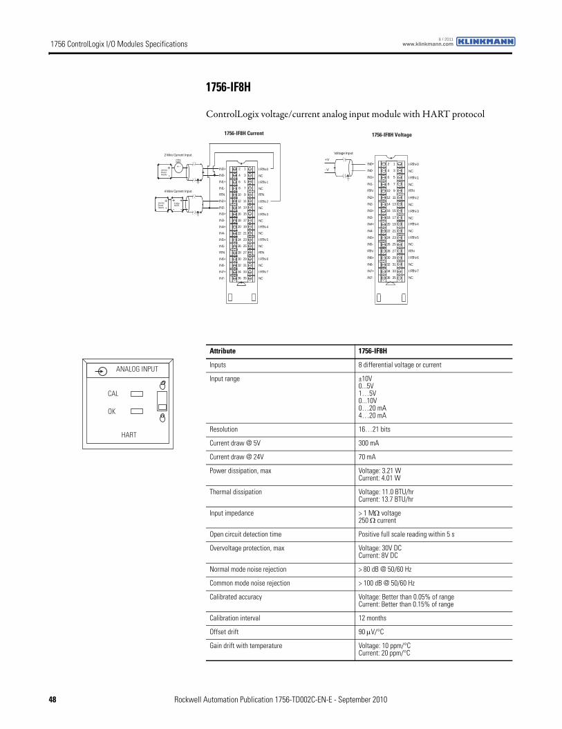
1756 ControlLogix I/O Modules Specifications www.klinkmann.com6 / 2011
1756-IF8H
ControlLogix voltage/current analog input module with HART protocol
RTN
IN4+
IN4-
IN5+
IN5-
RTN
IN6+
IN6-
IN7+
IN7-
IN0+
IN0-
IN1+
IN1-
IN2+
IN2-
IN3+
IN3-
I RTN-0
NC
I RTN-1
NC
I RTN-2
NC
I RTN-3
NC
RTN
I RTN-4
NC
I RTN-5
NC
RTN
I RTN-6
NC
I RTN-7
NC
2
4
6
8
10
12
14
16
18
20
22
24
26
28
30
32
34
36
1
3
5
7
9
11
13
15
17
19
21
23
25
27
29
31
33
35
2 Wire Current Input2 WireXMTR
+-
24V DCPowerSupply
+-
24V DCPowerSupply
4 Wire Current Input
4 WireXMTR
+ +
- -
+ -
1756-IF8H Current
RTN
IN4+
IN4-
IN5+
IN5-
RTN
IN6+
IN6-
IN7+
IN7-
IN0+
IN0-
IN1+
IN1-
IN2+
IN2-
IN3+
IN3-
I RTN-0
NC
I RTN-1
NC
I RTN-2
NC
I RTN-3
NC
RTN
I RTN-4
NC
I RTN-5
NC
RTN
I RTN-6
NC
I RTN-7
NC
2
4
6
8
10
12
14
16
18
20
22
24
26
28
30
32
34
36
1
3
5
7
9
11
13
15
17
19
21
23
25
27
29
31
33
35
+V
- V
Voltage Input
1756-IF8H Voltage
Attribute 1756-IF8H
Inputs 8 differential voltage or current
Input range ±10V0...5V1…5V0...10V0…20 mA4…20 mA
Resolution 16…21 bits
Current draw @ 5V 300 mA
Current draw @ 24V 70 mA
Power dissipation, max Voltage: 3.21 WCurrent: 4.01 W
Thermal dissipation Voltage: 11.0 BTU/hrCurrent: 13.7 BTU/hr
Input impedance > 1 MΩ voltage250 Ω current
Open circuit detection time Positive full scale reading within 5 s
Overvoltage protection, max Voltage: 30V DCCurrent: 8V DC
Normal mode noise rejection > 80 dB @ 50/60 Hz
Common mode noise rejection > 100 dB @ 50/60 Hz
Calibrated accuracy Voltage: Better than 0.05% of rangeCurrent: Better than 0.15% of range
Calibration interval 12 months
Offset drift 90 μV/°C
Gain drift with temperature Voltage: 10 ppm/°CCurrent: 20 ppm/°C
ANALOG INPUT
CAL
OK
HART
48 Rockwell Automation Publication 1756-TD002C-EN-E - September 2010
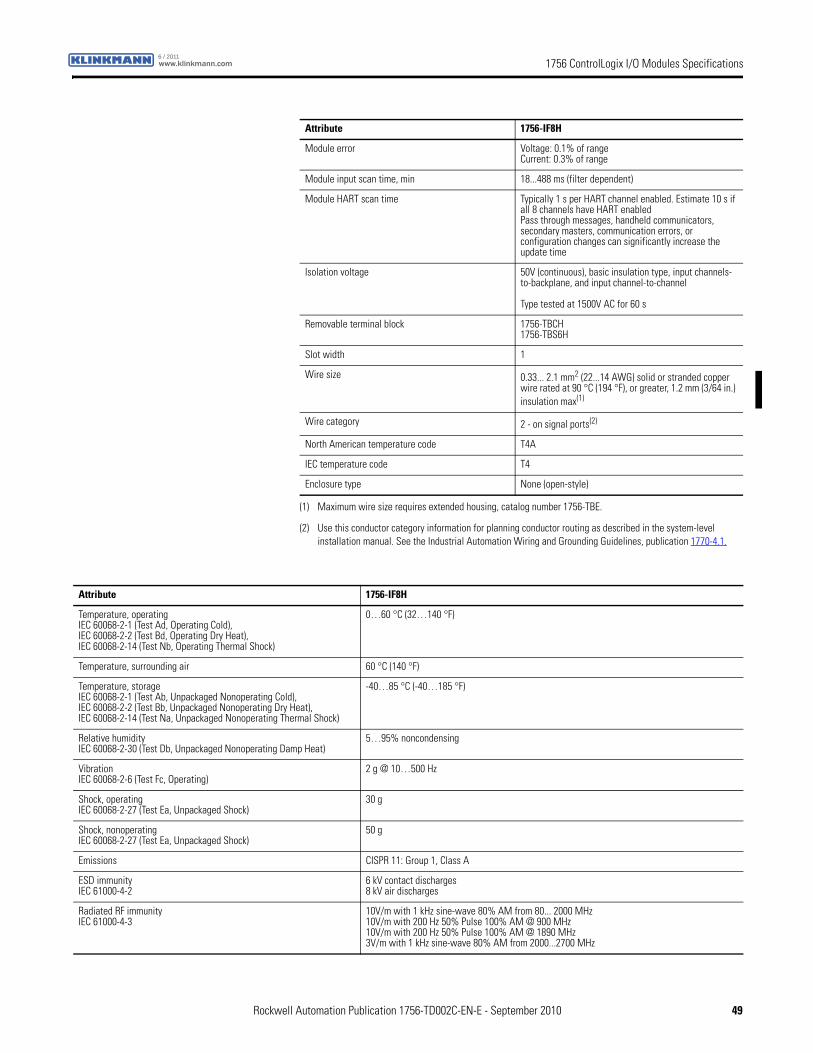
1756 ControlLogix I/O Modules Specificationswww.klinkmann.com6 / 2011
Module error Voltage: 0.1% of rangeCurrent: 0.3% of range
Module input scan time, min 18...488 ms (filter dependent)
Module HART scan time Typically 1 s per HART channel enabled. Estimate 10 s if all 8 channels have HART enabledPass through messages, handheld communicators, secondary masters, communication errors, or configuration changes can significantly increase the update time
Isolation voltage 50V (continuous), basic insulation type, input channels-to-backplane, and input channel-to-channel
Type tested at 1500V AC for 60 s
Removable terminal block 1756-TBCH1756-TBS6H
Slot width 1
Wire size 0.33... 2.1 mm2 (22...14 AWG) solid or stranded copper wire rated at 90 °C (194 °F), or greater, 1.2 mm (3/64 in.) insulation max(1)
Wire category 2 - on signal ports(2)
North American temperature code T4A
IEC temperature code T4
Enclosure type None (open-style)
(1) Maximum wire size requires extended housing, catalog number 1756-TBE.
(2) Use this conductor category information for planning conductor routing as described in the system-level installation manual. See the Industrial Automation Wiring and Grounding Guidelines, publication 1770-4.1.
Attribute 1756-IF8H
Attribute 1756-IF8H
Temperature, operatingIEC 60068-2-1 (Test Ad, Operating Cold),IEC 60068-2-2 (Test Bd, Operating Dry Heat),IEC 60068-2-14 (Test Nb, Operating Thermal Shock)
0…60 °C (32…140 °F)
Temperature, surrounding air 60 °C (140 °F)
Temperature, storageIEC 60068-2-1 (Test Ab, Unpackaged Nonoperating Cold),IEC 60068-2-2 (Test Bb, Unpackaged Nonoperating Dry Heat),IEC 60068-2-14 (Test Na, Unpackaged Nonoperating Thermal Shock)
-40…85 °C (-40…185 °F)
Relative humidityIEC 60068-2-30 (Test Db, Unpackaged Nonoperating Damp Heat)
5…95% noncondensing
VibrationIEC 60068-2-6 (Test Fc, Operating)
2 g @ 10…500 Hz
Shock, operatingIEC 60068-2-27 (Test Ea, Unpackaged Shock)
30 g
Shock, nonoperatingIEC 60068-2-27 (Test Ea, Unpackaged Shock)
50 g
Emissions CISPR 11: Group 1, Class A
ESD immunityIEC 61000-4-2
6 kV contact discharges8 kV air discharges
Radiated RF immunityIEC 61000-4-3
10V/m with 1 kHz sine-wave 80% AM from 80... 2000 MHz10V/m with 200 Hz 50% Pulse 100% AM @ 900 MHz10V/m with 200 Hz 50% Pulse 100% AM @ 1890 MHz3V/m with 1 kHz sine-wave 80% AM from 2000...2700 MHz
Rockwell Automation Publication 1756-TD002C-EN-E - September 2010 49
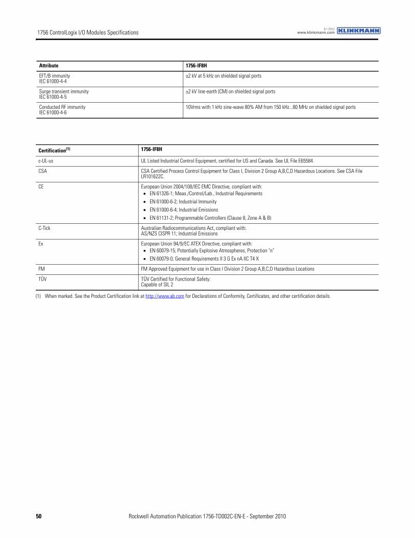
1756 ControlLogix I/O Modules Specifications www.klinkmann.com6 / 2011
EFT/B immunityIEC 61000-4-4
±2 kV at 5 kHz on shielded signal ports
Surge transient immunityIEC 61000-4-5
±2 kV line-earth (CM) on shielded signal ports
Conducted RF immunityIEC 61000-4-6
10Vrms with 1 kHz sine-wave 80% AM from 150 kHz...80 MHz on shielded signal ports
Attribute 1756-IF8H
Certification(1) 1756-IF8H
c-UL-us UL Listed Industrial Control Equipment, certified for US and Canada. See UL File E65584.
CSA CSA Certified Process Control Equipment for Class I, Division 2 Group A,B,C,D Hazardous Locations. See CSA File LR101622C.
CE European Union 2004/108/IEC EMC Directive, compliant with:• EN 61326-1; Meas./Control/Lab., Industrial Requirements
• EN 61000-6-2; Industrial Immunity
• EN 61000-6-4; Industrial Emissions
• EN 61131-2; Programmable Controllers (Clause 8, Zone A & B)
C-Tick Australian Radiocommunications Act, compliant with:AS/NZS CISPR 11; Industrial Emissions
Ex European Union 94/9/EC ATEX Directive, compliant with:• EN 60079-15; Potentially Explosive Atmospheres, Protection "n"
• EN 60079-0; General Requirements II 3 G Ex nA IIC T4 X
FM FM Approved Equipment for use in Class I Division 2 Group A,B,C,D Hazardous Locations
TÜV TÜV Certified for Functional Safety:Capable of SIL 2
(1) When marked. See the Product Certification link at http://www.ab.com for Declarations of Conformity, Certificates, and other certification details.
50 Rockwell Automation Publication 1756-TD002C-EN-E - September 2010
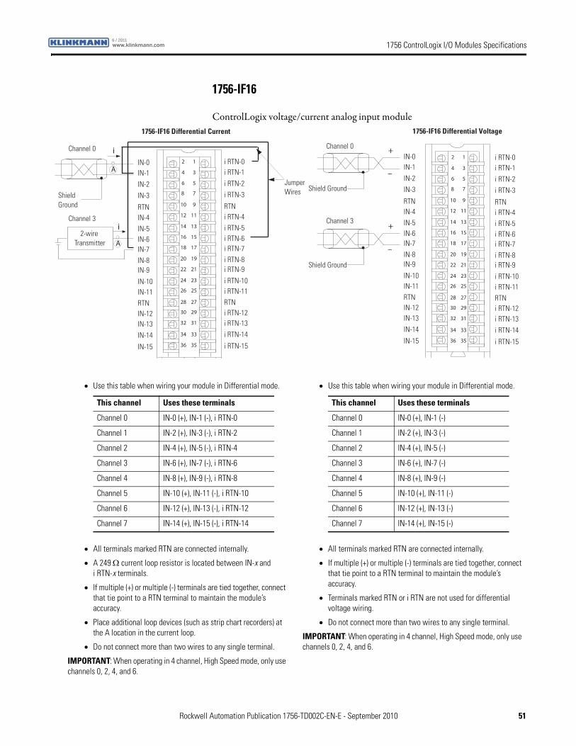
1756 ControlLogix I/O Modules Specificationswww.klinkmann.com6 / 2011
1756-IF16
ControlLogix voltage/current analog input module
12
34
56
78
910
1112
1314
1516
1718
1920
2122
2324
2526
2728
2930
3132
3334
3536
Shield Ground
Channel 0
Channel 3
Jumper Wires
i
i
A
2-wire Transmitter A
1756-IF16 Differential Current
IN-0IN-1
IN-2IN-3
IN-7
RTNIN-4IN-5IN-6
IN-15
IN-8IN-9
IN-10IN-11RTNIN-12IN-13IN-14
i RTN-0i RTN-1
i RTN-2i RTN-3
i RTN-7
RTNi RTN-4i RTN-5i RTN-6
i RTN-15
i RTN-8i RTN-9
i RTN-10i RTN-11RTNi RTN-12i RTN-13i RTN-14
12
34
56
78
910
1112
1314
1516
1718
1920
2122
2324
2526
2728
2930
3132
3334
3536
+
–
+
–
Shield Ground
Channel 0
Channel 3
1756-IF16 Differential Voltage
IN-0IN-1IN-2IN-3
IN-7
RTNIN-4IN-5IN-6
IN-15
IN-8IN-9
IN-10IN-11RTNIN-12IN-13IN-14
i RTN-0i RTN-1i RTN-2i RTN-3
i RTN-7
RTNi RTN-4i RTN-5i RTN-6
i RTN-15
i RTN-8i RTN-9
i RTN-10i RTN-11RTNi RTN-12i RTN-13i RTN-14
Shield Ground
• Use this table when wiring your module in Differential mode.
• All terminals marked RTN are connected internally.
• A 249 Ω current loop resistor is located between IN-x and i RTN-x terminals.
• If multiple (+) or multiple (-) terminals are tied together, connect that tie point to a RTN terminal to maintain the module’s accuracy.
• Place additional loop devices (such as strip chart recorders) at the A location in the current loop.
• Do not connect more than two wires to any single terminal.
IMPORTANT: When operating in 4 channel, High Speed mode, only use channels 0, 2, 4, and 6.
This channel Uses these terminals
Channel 0 IN-0 (+), IN-1 (-), i RTN-0
Channel 1 IN-2 (+), IN-3 (-), i RTN-2
Channel 2 IN-4 (+), IN-5 (-), i RTN-4
Channel 3 IN-6 (+), IN-7 (-), i RTN-6
Channel 4 IN-8 (+), IN-9 (-), i RTN-8
Channel 5 IN-10 (+), IN-11 (-), i RTN-10
Channel 6 IN-12 (+), IN-13 (-), i RTN-12
Channel 7 IN-14 (+), IN-15 (-), i RTN-14
• Use this table when wiring your module in Differential mode.
• All terminals marked RTN are connected internally.
• If multiple (+) or multiple (-) terminals are tied together, connect that tie point to a RTN terminal to maintain the module’s accuracy.
• Terminals marked RTN or i RTN are not used for differential voltage wiring.
• Do not connect more than two wires to any single terminal.
IMPORTANT: When operating in 4 channel, High Speed mode, only use channels 0, 2, 4, and 6.
This channel Uses these terminals
Channel 0 IN-0 (+), IN-1 (-)
Channel 1 IN-2 (+), IN-3 (-)
Channel 2 IN-4 (+), IN-5 (-)
Channel 3 IN-6 (+), IN-7 (-)
Channel 4 IN-8 (+), IN-9 (-)
Channel 5 IN-10 (+), IN-11 (-)
Channel 6 IN-12 (+), IN-13 (-)
Channel 7 IN-14 (+), IN-15 (-)
Rockwell Automation Publication 1756-TD002C-EN-E - September 2010 51
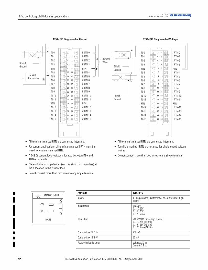
1756 ControlLogix I/O Modules Specifications www.klinkmann.com6 / 2011
12
34
56
78
910
1112
1314
1516
1718
1920
2122
2324
2526
2728
2930
3132
3334
3536
Shield Ground
Jumper Wires
i
i
A
2-wire Transmitter
1756-IF16 Single-ended Current
IN-0IN-1IN-2IN-3
IN-7
RTNIN-4IN-5IN-6
IN-15
IN-8IN-9
IN-10IN-11RTNIN-12IN-13IN-14
i RTN-0i RTN-1i RTN-2i RTN-3
i RTN-7
RTNi RTN-4i RTN-5i RTN-6
i RTN-15
i RTN-8i RTN-9
i RTN-10i RTN-11RTNi RTN-12i RTN-13i RTN-14
12
34
56
78
910
1112
1314
1516
1718
1920
2122
2324
2526
2728
2930
3132
3334
3536
+
–
+
–
Shield Ground
1756-IF16 Single-ended Voltage
IN-0IN-1
IN-2IN-3
IN-7
RTNIN-4IN-5IN-6
IN-15
IN-8IN-9
IN-10IN-11RTNIN-12IN-13
IN-14
i RTN-0i RTN-1
i RTN-2i RTN-3
i RTN-7
RTNi RTN-4i RTN-5i RTN-6
i RTN-15
i RTN-8i RTN-9
i RTN-10i RTN-11RTNi RTN-12i RTN-13
i RTN-14
Shield Ground
• All terminals marked RTN are connected internally.
• For current applications, all terminals marked i RTN must be wired to terminals marked RTN.
• A 249 Ω current loop resistor is located between IN-x and iRTN-x terminals.
• Place additional loop devices (such as strip chart recorders) at the A location in the current loop.
• Do not connect more than two wires to any single terminal.
• All terminals marked RTN are connected internally.
• Terminals marked i RTN are not used for single-ended voltage wiring.
• Do not connect more than two wires to any single terminal.
Attribute 1756-IF16
Inputs 16 single ended, 8 differential or 4 differential (high speed)
Input range ±10.25V0…10.25V0…5.125V0…20.5 mA
Resolution ±10.25V (15 bits + sign bipolar)0…10.25V (16 bits)0…5.125V (16 bits)0…20.5 mA (16 bits)
Current draw @ 5.1V 150 mA
Current draw @ 24V 65 mA
Power dissipation, max Voltage: 2.3 WCurrent: 3.9 W
ANALOG INPUT
CAL
OK
HART
52 Rockwell Automation Publication 1756-TD002C-EN-E - September 2010
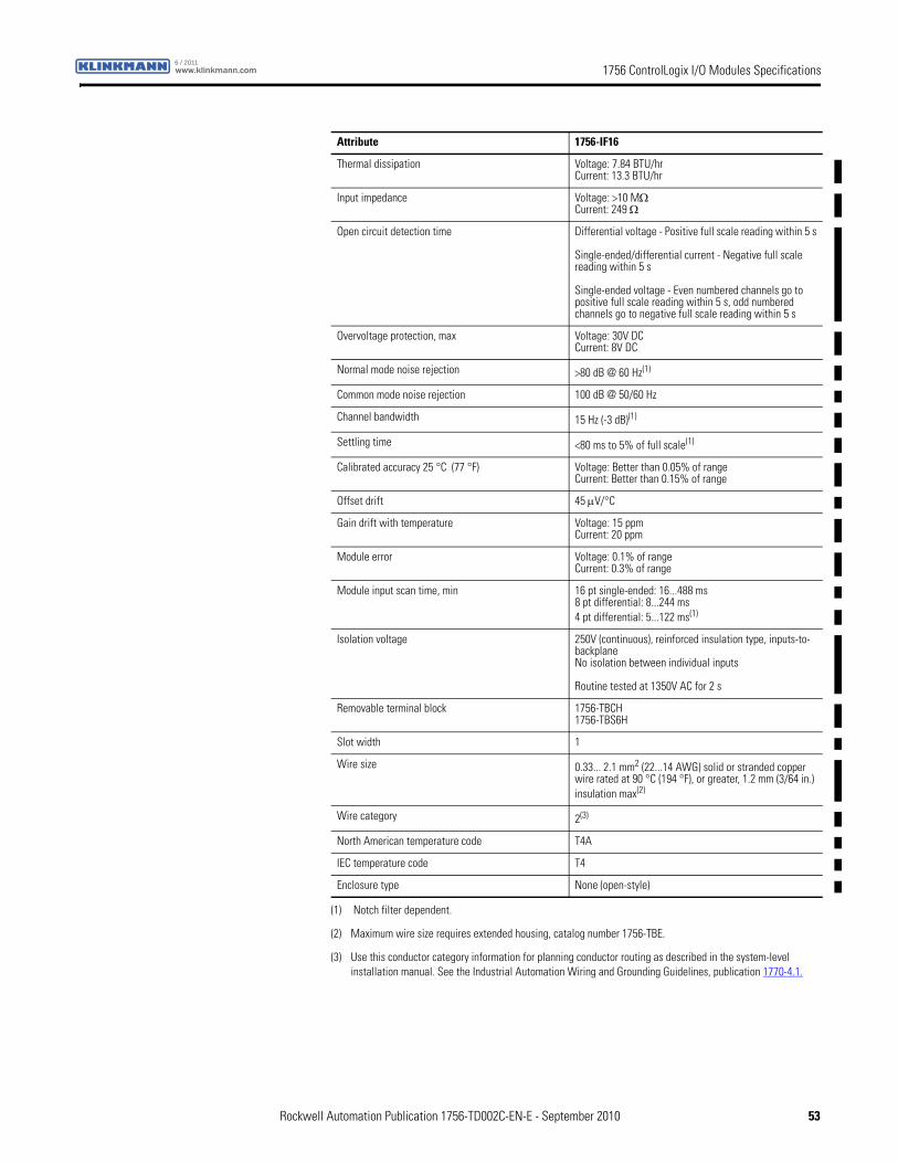
1756 ControlLogix I/O Modules Specificationswww.klinkmann.com6 / 2011
Thermal dissipation Voltage: 7.84 BTU/hrCurrent: 13.3 BTU/hr
Input impedance Voltage: >10 MΩCurrent: 249 Ω
Open circuit detection time Differential voltage - Positive full scale reading within 5 s
Single-ended/differential current - Negative full scale reading within 5 s
Single-ended voltage - Even numbered channels go to positive full scale reading within 5 s, odd numbered channels go to negative full scale reading within 5 s
Overvoltage protection, max Voltage: 30V DCCurrent: 8V DC
Normal mode noise rejection >80 dB @ 60 Hz(1)
Common mode noise rejection 100 dB @ 50/60 Hz
Channel bandwidth 15 Hz (-3 dB)(1)
Settling time <80 ms to 5% of full scale(1)
Calibrated accuracy 25 °C (77 °F) Voltage: Better than 0.05% of rangeCurrent: Better than 0.15% of range
Offset drift 45 μV/°C
Gain drift with temperature Voltage: 15 ppmCurrent: 20 ppm
Module error Voltage: 0.1% of rangeCurrent: 0.3% of range
Module input scan time, min 16 pt single-ended: 16...488 ms8 pt differential: 8...244 ms4 pt differential: 5...122 ms(1)
Isolation voltage 250V (continuous), reinforced insulation type, inputs-to-backplaneNo isolation between individual inputs
Routine tested at 1350V AC for 2 s
Removable terminal block 1756-TBCH1756-TBS6H
Slot width 1
Wire size 0.33... 2.1 mm2 (22...14 AWG) solid or stranded copper wire rated at 90 °C (194 °F), or greater, 1.2 mm (3/64 in.) insulation max(2)
Wire category 2(3)
North American temperature code T4A
IEC temperature code T4
Enclosure type None (open-style)
(1) Notch filter dependent.
(2) Maximum wire size requires extended housing, catalog number 1756-TBE.
(3) Use this conductor category information for planning conductor routing as described in the system-level installation manual. See the Industrial Automation Wiring and Grounding Guidelines, publication 1770-4.1.
Attribute 1756-IF16
Rockwell Automation Publication 1756-TD002C-EN-E - September 2010 53

1756 ControlLogix I/O Modules Specifications www.klinkmann.com6 / 2011
Attribute 1756-IF16
Temperature, operatingIEC 60068-2-1 (Test Ad, Operating Cold),IEC 60068-2-2 (Test Bd, Operating Dry Heat),IEC 60068-2-14 (Test Nb, Operating Thermal Shock)
0…60 °C (32…140 °F)
Temperature, surrounding air 60 °C (140 °F)
Temperature, storageIEC 60068-2-1 (Test Ab, Unpackaged Nonoperating Cold),IEC 60068-2-2 (Test Bb, Unpackaged Nonoperating Dry Heat),IEC 60068-2-14 (Test Na, Unpackaged Nonoperating Thermal Shock)
-40…85 °C (-40…185 °F)
Relative humidityIEC 60068-2-30 (Test Db, Unpackaged Nonoperating Damp Heat)
5…95% noncondensing
VibrationIEC 60068-2-6 (Test Fc, Operating)
2 g @ 10…500 Hz
Shock, operatingIEC 60068-2-27 (Test Ea, Unpackaged Shock)
30 g
Shock, nonoperatingIEC 60068-2-27 (Test Ea, Unpackaged Shock)
50 g
Emissions CISPR 11: Group 1, Class A
ESD immunityIEC 61000-4-2
6 kV contact discharges8 kV air discharges
Radiated RF immunityIEC 61000-4-3
10V/m with 1 kHz sine-wave 80% AM from 80... 2000 MHz10V/m with 200 Hz 50% Pulse 100% AM @ 900 MHz10V/m with 200 Hz 50% Pulse 100% AM @ 1890 MHz3V/m with 1 kHz sine-wave 80% AM from 2000...2700 MHz
EFT/B immunityIEC 61000-4-4
±2 kV at 5 kHz on shielded signal ports
Surge transient immunityIEC 61000-4-5
±2 kV line-earth (CM) on shielded signal ports
Conducted RF immunityIEC 61000-4-6
10Vrms with 1 kHz sine-wave 80% AM from 150 kHz...80 MHz on shielded signal ports
Certification(1) 1756-IF16
UL UL Listed Industrial Control Equipment, certified for US and Canada. See UL File E65584.
CSA CSA Certified Process Control Equipment. See CSA File LR54689C.
CSA Certified Process Control Equipment for Class I, Division 2 Group A,B,C,D Hazardous Locations. See CSA File LR69960C.
CE European Union 2004/108/IEC EMC Directive, compliant with:• EN 61326-1; Meas./Control/Lab., Industrial Requirements
• EN 61000-6-2; Industrial Immunity
• EN 61000-6-4; Industrial Emissions
• EN 61131-2; Programmable Controllers (Clause 8, Zone A & B)
European Union 2006/95/EC LVD, compliant with:• EN 61131-2; Programmable Controllers (Clause 11)
C-Tick Australian Radiocommunications Act, compliant with:AS/NZS CISPR 11; Industrial Emissions
Ex European Union 94/9/EC ATEX Directive, compliant with:• EN 60079-15; Potentially Explosive Atmospheres, Protection "n"
• EN 60079-0; General Requirements II 3 G Ex nA IIC T4 X
FM FM Approved Equipment for use in Class I Division 2 Group A,B,C,D Hazardous Locations
TÜV TÜV Certified for Functional Safety:Capable of SIL 2
(1) When marked. See the Product Certification link at http://www.ab.com for Declarations of Conformity, Certificates, and other certification details.
54 Rockwell Automation Publication 1756-TD002C-EN-E - September 2010
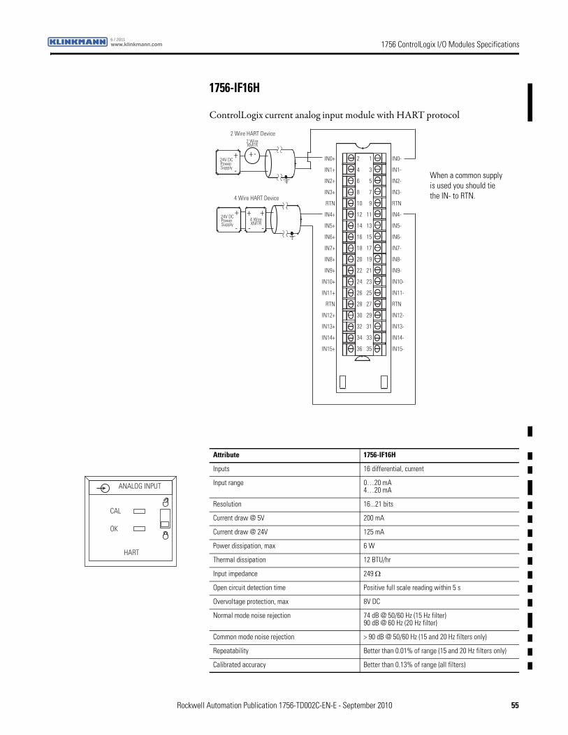
1756 ControlLogix I/O Modules Specificationswww.klinkmann.com6 / 2011
1756-IF16H
ControlLogix current analog input module with HART protocol
+
-
+
-
+
- -
+ -
2 Wire HART Device
4 Wire HART Device
IN0+
IN1+
IN2+
IN3+
RTN
IN4+
IN5+
IN6+
IN7+
IN8+
IN9+
IN10+
IN11+
RTN
IN12+
IN13+
IN14+
IN15+
IN0-
IN1-
IN2-
IN3-
RTN
IN4-
IN5-
IN6-
IN7-
IN8-
IN9-
IN10-
IN11-
RTN
IN12-
IN13-
IN14-
IN15-
2
4
6
8
10
12
14
16
18
20
22
24
26
28
30
32
34
36
1
3
5
7
9
11
13
15
17
19
21
23
25
27
29
31
33
35
24V DCPower Supply
24V DCPower Supply
4 WireXMTR
2 WireXMTR
+
When a common supply is used you should tie the IN- to RTN.
Attribute 1756-IF16H
Inputs 16 differential, current
Input range 0…20 mA4…20 mA
Resolution 16...21 bits
Current draw @ 5V 200 mA
Current draw @ 24V 125 mA
Power dissipation, max 6 W
Thermal dissipation 12 BTU/hr
Input impedance 249 Ω
Open circuit detection time Positive full scale reading within 5 s
Overvoltage protection, max 8V DC
Normal mode noise rejection 74 dB @ 50/60 Hz (15 Hz filter)90 dB @ 60 Hz (20 Hz filter)
Common mode noise rejection > 90 dB @ 50/60 Hz (15 and 20 Hz filters only)
Repeatability Better than 0.01% of range (15 and 20 Hz filters only)
Calibrated accuracy Better than 0.13% of range (all filters)
ANALOG INPUT
CAL
OK
HART
Rockwell Automation Publication 1756-TD002C-EN-E - September 2010 55
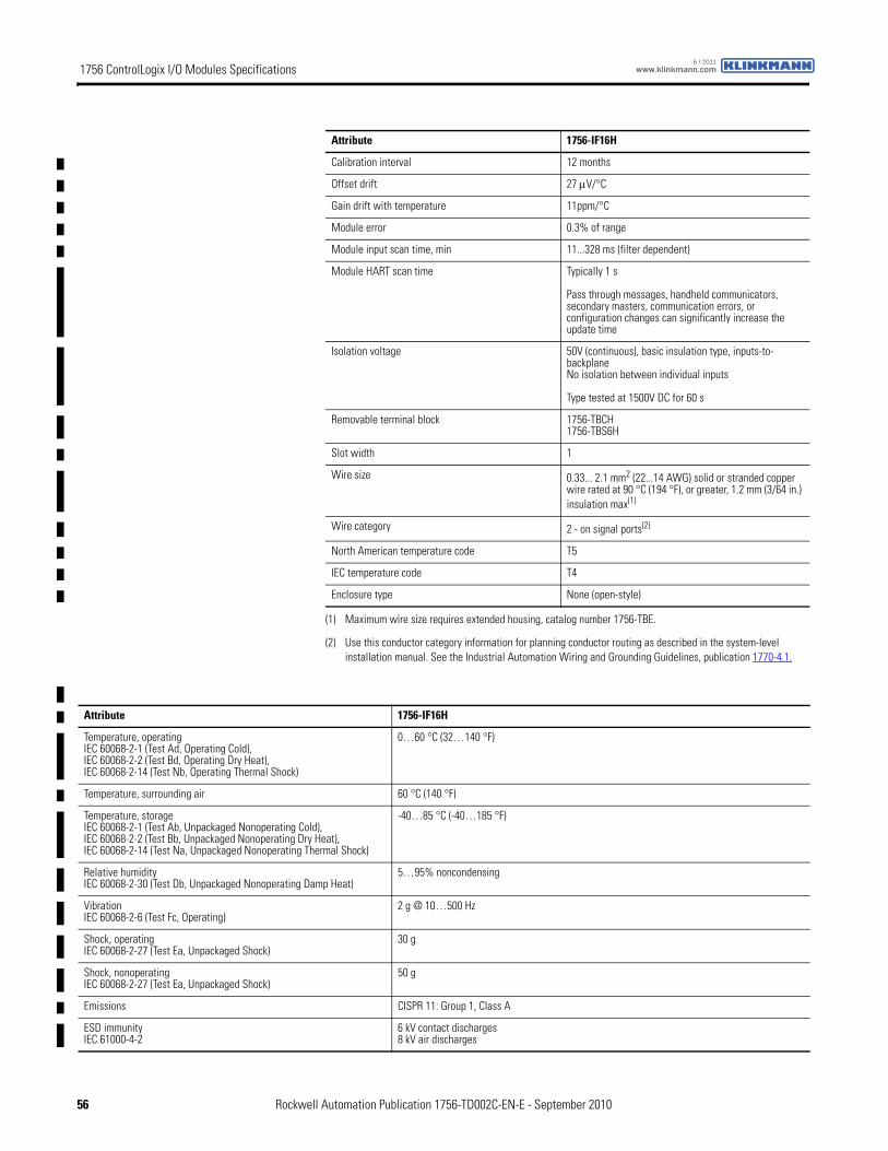
1756 ControlLogix I/O Modules Specifications www.klinkmann.com6 / 2011
Calibration interval 12 months
Offset drift 27 μV/°C
Gain drift with temperature 11ppm/°C
Module error 0.3% of range
Module input scan time, min 11...328 ms (filter dependent)
Module HART scan time Typically 1 s
Pass through messages, handheld communicators, secondary masters, communication errors, or configuration changes can significantly increase the update time
Isolation voltage 50V (continuous), basic insulation type, inputs-to-backplaneNo isolation between individual inputs
Type tested at 1500V DC for 60 s
Removable terminal block 1756-TBCH1756-TBS6H
Slot width 1
Wire size 0.33... 2.1 mm2 (22...14 AWG) solid or stranded copper wire rated at 90 °C (194 °F), or greater, 1.2 mm (3/64 in.) insulation max(1)
Wire category 2 - on signal ports(2)
North American temperature code T5
IEC temperature code T4
Enclosure type None (open-style)
(1) Maximum wire size requires extended housing, catalog number 1756-TBE.
(2) Use this conductor category information for planning conductor routing as described in the system-level installation manual. See the Industrial Automation Wiring and Grounding Guidelines, publication 1770-4.1.
Attribute 1756-IF16H
Attribute 1756-IF16H
Temperature, operatingIEC 60068-2-1 (Test Ad, Operating Cold),IEC 60068-2-2 (Test Bd, Operating Dry Heat),IEC 60068-2-14 (Test Nb, Operating Thermal Shock)
0…60 °C (32…140 °F)
Temperature, surrounding air 60 °C (140 °F)
Temperature, storageIEC 60068-2-1 (Test Ab, Unpackaged Nonoperating Cold),IEC 60068-2-2 (Test Bb, Unpackaged Nonoperating Dry Heat),IEC 60068-2-14 (Test Na, Unpackaged Nonoperating Thermal Shock)
-40…85 °C (-40…185 °F)
Relative humidityIEC 60068-2-30 (Test Db, Unpackaged Nonoperating Damp Heat)
5…95% noncondensing
VibrationIEC 60068-2-6 (Test Fc, Operating)
2 g @ 10…500 Hz
Shock, operatingIEC 60068-2-27 (Test Ea, Unpackaged Shock)
30 g
Shock, nonoperatingIEC 60068-2-27 (Test Ea, Unpackaged Shock)
50 g
Emissions CISPR 11: Group 1, Class A
ESD immunityIEC 61000-4-2
6 kV contact discharges8 kV air discharges
56 Rockwell Automation Publication 1756-TD002C-EN-E - September 2010
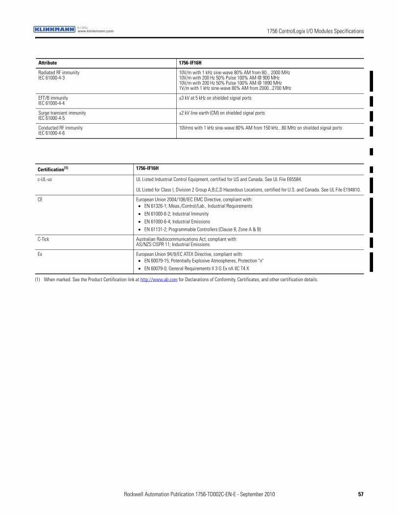
1756 ControlLogix I/O Modules Specificationswww.klinkmann.com6 / 2011
Radiated RF immunityIEC 61000-4-3
10V/m with 1 kHz sine-wave 80% AM from 80... 2000 MHz10V/m with 200 Hz 50% Pulse 100% AM @ 900 MHz10V/m with 200 Hz 50% Pulse 100% AM @ 1890 MHz1V/m with 1 kHz sine-wave 80% AM from 2000...2700 MHz
EFT/B immunityIEC 61000-4-4
±3 kV at 5 kHz on shielded signal ports
Surge transient immunityIEC 61000-4-5
±2 kV line-earth (CM) on shielded signal ports
Conducted RF immunityIEC 61000-4-6
10Vrms with 1 kHz sine-wave 80% AM from 150 kHz...80 MHz on shielded signal ports
Attribute 1756-IF16H
Certification(1) 1756-IF16H
c-UL-us UL Listed Industrial Control Equipment, certified for US and Canada. See UL File E65584.
UL Listed for Class I, Division 2 Group A,B,C,D Hazardous Locations, certified for U.S. and Canada. See UL File E194810.
CE European Union 2004/108/IEC EMC Directive, compliant with:• EN 61326-1; Meas./Control/Lab., Industrial Requirements
• EN 61000-6-2; Industrial Immunity
• EN 61000-6-4; Industrial Emissions
• EN 61131-2; Programmable Controllers (Clause 8, Zone A & B)
C-Tick Australian Radiocommunications Act, compliant with:AS/NZS CISPR 11; Industrial Emissions
Ex European Union 94/9/EC ATEX Directive, compliant with:• EN 60079-15; Potentially Explosive Atmospheres, Protection "n"
• EN 60079-0; General Requirements II 3 G Ex nA IIC T4 X
(1) When marked. See the Product Certification link at http://www.ab.com for Declarations of Conformity, Certificates, and other certification details.
Rockwell Automation Publication 1756-TD002C-EN-E - September 2010 57
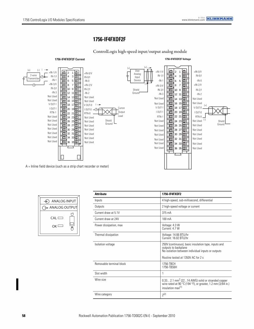
1756 ControlLogix I/O Modules Specifications www.klinkmann.com6 / 2011
1756-IF4FXOF2F
ControlLogix high-speed input/output analog module
+IN-1/VIN-1/I-IN-1
+IN-3/V
V OUT-1
IN-3/I-IN-3
Not UsedNot Used
I OUT-1RTN-1
Not Used
+IN-0/VIN-0/I-IN-0
+IN-2/VIN-2/I-IN-2
1756-IF4FXOF2F Current
2-wire Transmitter
A
A
A
(+) (-) i
i
Shield Ground
CurrenOutput Load
Not Used
Not UsedNot Used
Not Used
Not Used
Not Used
V OUT-0
Not UsedNot Used
I OUT-0
Not UsedNot Used
Not UsedNot Used
Not Used
Not Used
Not Used
RTN-0
24
6
81012
141618
20
22242628
303234
36
13
5
7911
131517
19
21232527
293133
35
1756-IF4FXOF2F Voltage
User Analog Input
Device
(+)
(-)
Shield Ground
(+)
(+)
(-)
Shield Ground
+IN-1/VIN-1/I
-IN-1
+IN-3/V
V OUT-1
IN-3/I-IN-3
Not Used
Not Used
I OUT-1
RTN-1
Not Used
+IN-0/VIN-0/I
-IN-0
+IN-2/V
IN-2/I
-IN-2
Not Used
Not Used
Not Used
Not UsedNot Used
Not Used
V OUT-0
Not Used
Not Used
I OUT-0
Not Used
Not Used
Not Used
Not Used
Not Used
Not Used
Not Used
RTN-0
2
4
6
8
10
12
14
16
18
20
22
24
26
28
30
32
34
36
1
3
5
7
9
11
13
15
17
19
21
23
25
27
29
31
33
35
A = Inline field device (such as a strip chart recorder or meter)
Attribute 1756-IF4FXOF2
Inputs 4 high-speed, sub-millisecond, differential
Outputs 2 high-speed voltage or current
Current draw at 5.1V 375 mA
Current draw at 24V 100 mA
Power dissipation, max Voltage: 4.3 WCurrent: 4.7 W
Thermal dissipation Voltage: 14.66 BTU/hrCurrent: 16.02 BTU/hr
Isolation voltage 250V (continuous), basic insulation type, inputs and outputs to backplaneNo isolation between individual inputs or outputs
Routine tested at 1350V AC for 2 s
Removable terminal block 1756-TBCH1756-TBS6H
Slot width 1
Wire size 0.33... 2.1 mm2 (22...14 AWG) solid or stranded copper wire rated at 90 °C (194 °F), or greater, 1.2 mm (3/64 in.) insulation max(1)
Wire category 2(2)
ANALOG INPUT
ANALOG OUTPUT
CAL
OK
58 Rockwell Automation Publication 1756-TD002C-EN-E - September 2010
1756 ControlLogix I/O Modules Specificationswww.klinkmann.com6 / 2011
North American temperature code T4A
IEC temperature code T4
Enclosure type None (open-style)
(1) Maximum wire size requires extended housing, catalog number 1756-TBE.
(2) Use this conductor category information for planning conductor routing as described in the system-level installation manual. See the Industrial Automation Wiring and Grounding Guidelines, publication 1770-4.1.
Attribute 1756-IF4FXOF2
Attribute Inputs Outputs
Number 4 high-speed, sub-millisecond, differential 2 high-speed voltage or current
Output range ± 10.5V0…10.5V0…5.25V0…21 mA
± 10.4V0…21 mA
Resolution Approx. 14 bits across ±10V DC (21V total)±10V: 1.3 mV/bit, 14-bit effective0…10.5V: 1.3 mV/bit, 13-bit effective0…5.25V: 1.3 mV/bit, 12-bit effectiveApprox. 12 bits across 21 mA0…21 mA: 5.25 μA/bit
13 bits across 21 mA = 2.8 μA/bit14 bits across 21.8V = 1.3 mV/bit
Impedance Voltage: >1 MΩCurrent: 249 Ω
—
Open circuit detection Positive full-scale reading within 1 s Current output only (Output must be set to >0.1 mA)
Overvoltage protection Voltage: 30V DCCurrent: 8V AC/DC
24V DC
Short circuit protection — Electronically current limited to 21 mA or less
Drive capability — Voltage: >2000 ΩCurrent: 0…750 Ω
Settling time — < 2 ms to 95% of final value with resistive loads
Calibrated accuracy @ 25 °C (77 °F) 0.05% of range immediately after calibrationBetter than 0.1% of range within calibration interval
Calibration interval 12 months
Offset drift — 50 μV/° C1 μA/° C
Gain drift with temperature Voltage: 25 ppm/°C maxCurrent: 35 ppm/°C max
Voltage: 25 ppm/°C maxCurrent: 50 ppm/°C max
Module error 0.2% of range Voltage: 0.2% of rangeCurrent: 0.3% of range
Module scan time 300 μs min(1)
(1) 300 μs min for 1756-IF4FXOF2F, Series B, firmware revision 3.x or greater. 400 μs min for 1756-IF4FXOF2F, Series A, firmware revision 1.x.
Attribute 1756-IF4FXOF2
Temperature, operatingIEC 60068-2-1 (Test Ad, Operating Cold),IEC 60068-2-2 (Test Bd, Operating Dry Heat),IEC 60068-2-14 (Test Nb, Operating Thermal Shock)
0…60 °C (32…140 °F)
Temperature, surrounding air 60 °C (140 °F)
Temperature, storageIEC 60068-2-1 (Test Ab, Unpackaged Nonoperating Cold),IEC 60068-2-2 (Test Bb, Unpackaged Nonoperating Dry Heat),IEC 60068-2-14 (Test Na, Unpackaged Nonoperating Thermal Shock)
-40…85 °C (-40…185 °F)
Rockwell Automation Publication 1756-TD002C-EN-E - September 2010 59
1756 ControlLogix I/O Modules Specifications www.klinkmann.com6 / 2011
Relative humidityIEC 60068-2-30 (Test Db, Unpackaged Nonoperating Damp Heat)
5…95% noncondensing
VibrationIEC 60068-2-6 (Test Fc, Operating)
2 g @ 10…500 Hz
Shock, operatingIEC 60068-2-27 (Test Ea, Unpackaged Shock)
30 g
Shock, nonoperatingIEC 60068-2-27 (Test Ea, Unpackaged Shock)
50 g
Emissions CISPR 11: Group 1, Class A
ESD immunityIEC 61000-4-2
6 kV contact discharges8 kV air discharges
Radiated RF immunityIEC 61000-4-3
10V/m with 1 kHz sine-wave 80% AM from 80... 2000 MHz10V/m with 200 Hz 50% Pulse 100% AM @ 900 MHz10V/m with 200 Hz 50% Pulse 100% AM @ 1890 MHz3V/m with 1 kHz sine-wave 80% AM from 2000...2700 MHz
EFT/B immunityIEC 61000-4-4
±2 kV at 5 kHz on shielded signal ports
Surge transient immunityIEC 61000-4-5
±2 kV line-earth (CM) on shielded signal ports
Conducted RF immunityIEC 61000-4-6
10Vrms with 1 kHz sine-wave 80% AM from 150 kHz...80 MHz on shielded signal ports
Attribute 1756-IF4FXOF2
Certification(1) 1756-IF4FXOF2
UL UL Listed Industrial Control Equipment, certified for US and Canada. See UL File E65584.
CSA CSA Certified Process Control Equipment. See CSA File LR54689C.
CSA Certified Process Control Equipment for Class I, Division 2 Group A,B,C,D Hazardous Locations. See CSA File LR69960C.
CE European Union 2004/108/IEC EMC Directive, compliant with:• EN 61326-1; Meas./Control/Lab., Industrial Requirements
• EN 61000-6-2; Industrial Immunity
• EN 61000-6-4; Industrial Emissions
• EN 61131-2; Programmable Controllers (Clause 8, Zone A & B)
European Union 2006/95/EC LVD, compliant with:• EN 61131-2; Programmable Controllers (Clause 11)
C-Tick Australian Radiocommunications Act, compliant with:AS/NZS CISPR 11; Industrial Emissions
Ex European Union 94/9/EC ATEX Directive, compliant with:• EN 60079-15; Potentially Explosive Atmospheres, Protection "n"
• EN 60079-0; General Requirements II 3 G Ex nA IIC T4 X
FM FM Approved Equipment for use in Class I Division 2 Group A,B,C,D Hazardous Locations
TÜV TÜV Certified for Functional Safety:Capable of SIL 2
(1) When marked. See the Product Certification link at http://www.ab.com for Declarations of Conformity, Certificates, and other certification details.
60 Rockwell Automation Publication 1756-TD002C-EN-E - September 2010
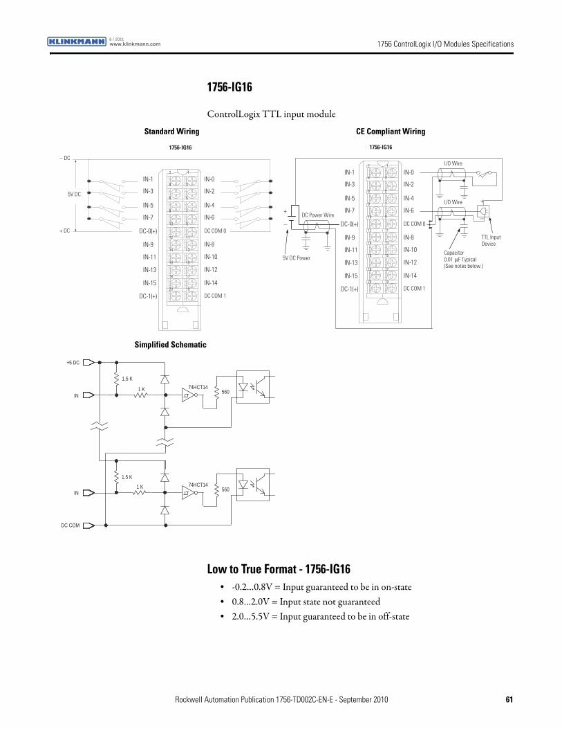
1756 ControlLogix I/O Modules Specificationswww.klinkmann.com6 / 2011
1756-IG16
ControlLogix TTL input module
Low to True Format - 1756-IG16• -0.2…0.8V = Input guaranteed to be in on-state• 0.8…2.0V = Input state not guaranteed• 2.0…5.5V = Input guaranteed to be in off-state
1
3
5
7
9
19
17
15
13
11
2
4
6
8
10
20
18
16
14
12
IN-1
IN-3
IN-5
IN-7
DC-0(+)
IN-0
IN-2
IN-4
IN-6
DC COM 0
IN-9
IN-11
IN-13
IN-15
DC-1(+)
IN-8
IN-10
IN-12
IN-14
DC COM 1
5V DC
+ DC
– DC
1756-IG16
1
3
5
7
9
19
17
15
13
11
2
4
6
8
10
20
18
16
14
12
IN-1
IN-3
IN-5
IN-7
DC-0(+)
IN-0
IN-2
IN-4
IN-6
DC COM 0
IN-9
IN-11
IN-13
IN-15
DC-1(+)
IN-8
IN-10
IN-12
IN-14
DC COM 1
Capacitor0.01 μF Typical (See notes below.)
5V DC Power
DC Power Wire
I/O Wire
+
–
I/O Wire
TTL Input Device
+
–
1756-IG16
+5 DC
IN
1.5 K
1 K 74HCT14
1.5 K
1 K
560
74HCT14560
DC COM
IN
Standard Wiring CE Compliant Wiring
Simplified Schematic
Rockwell Automation Publication 1756-TD002C-EN-E - September 2010 61
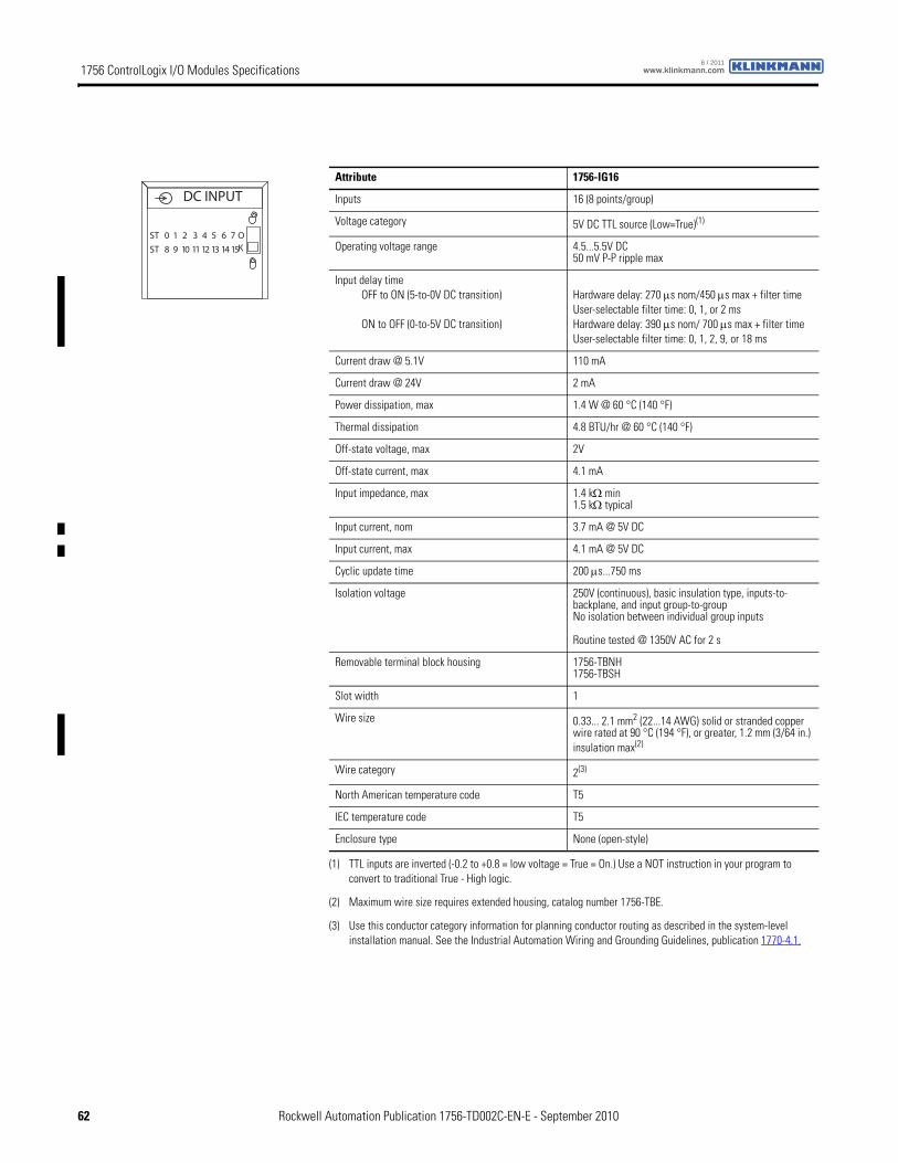
1756 ControlLogix I/O Modules Specifications www.klinkmann.com6 / 2011
Attribute 1756-IG16
Inputs 16 (8 points/group)
Voltage category 5V DC TTL source (Low=True)(1)
(1) TTL inputs are inverted (-0.2 to +0.8 = low voltage = True = On.) Use a NOT instruction in your program to convert to traditional True - High logic.
Operating voltage range 4.5...5.5V DC 50 mV P-P ripple max
Input delay timeOFF to ON (5-to-0V DC transition)
ON to OFF (0-to-5V DC transition)
Hardware delay: 270 μs nom/450 μs max + filter timeUser-selectable filter time: 0, 1, or 2 msHardware delay: 390 μs nom/ 700 μs max + filter timeUser-selectable filter time: 0, 1, 2, 9, or 18 ms
Current draw @ 5.1V 110 mA
Current draw @ 24V 2 mA
Power dissipation, max 1.4 W @ 60 °C (140 °F)
Thermal dissipation 4.8 BTU/hr @ 60 °C (140 °F)
Off-state voltage, max 2V
Off-state current, max 4.1 mA
Input impedance, max 1.4 kΩ min1.5 kΩ typical
Input current, nom 3.7 mA @ 5V DC
Input current, max 4.1 mA @ 5V DC
Cyclic update time 200 μs...750 ms
Isolation voltage 250V (continuous), basic insulation type, inputs-to-backplane, and input group-to-groupNo isolation between individual group inputs
Routine tested @ 1350V AC for 2 s
Removable terminal block housing 1756-TBNH1756-TBSH
Slot width 1
Wire size 0.33... 2.1 mm2 (22...14 AWG) solid or stranded copper wire rated at 90 °C (194 °F), or greater, 1.2 mm (3/64 in.) insulation max(2)
(2) Maximum wire size requires extended housing, catalog number 1756-TBE.
Wire category 2(3)
(3) Use this conductor category information for planning conductor routing as described in the system-level installation manual. See the Industrial Automation Wiring and Grounding Guidelines, publication 1770-4.1.
North American temperature code T5
IEC temperature code T5
Enclosure type None (open-style)
DC INPUT
ST 0 1 2 3 4 5 6 7
ST 8 9 10 11 12 13 14 15
OK
62 Rockwell Automation Publication 1756-TD002C-EN-E - September 2010
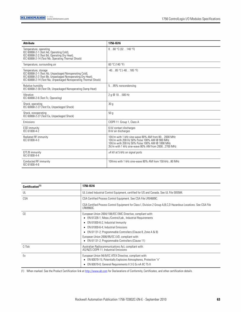
1756 ControlLogix I/O Modules Specificationswww.klinkmann.com6 / 2011
Attribute 1756-IG16
Temperature, operatingIEC 60068-2-1 (Test Ad, Operating Cold),IEC 60068-2-2 (Test Bd, Operating Dry Heat),IEC 60068-2-14 (Test Nb, Operating Thermal Shock)
0…60 °C (32…140 °F)
Temperature, surrounding air 60 °C (140 °F)
Temperature, storageIEC 60068-2-1 (Test Ab, Unpackaged Nonoperating Cold),IEC 60068-2-2 (Test Bb, Unpackaged Nonoperating Dry Heat),IEC 60068-2-14 (Test Na, Unpackaged Nonoperating Thermal Shock)
-40…85 °C (-40…185 °F)
Relative humidityIEC 60068-2-30 (Test Db, Unpackaged Nonoperating Damp Heat)
5…95% noncondensing
VibrationIEC 60068-2-6 (Test Fc, Operating)
2 g @ 10…500 Hz
Shock, operatingIEC 60068-2-27 (Test Ea, Unpackaged Shock)
30 g
Shock, nonoperatingIEC 60068-2-27 (Test Ea, Unpackaged Shock)
50 g
Emissions CISPR 11: Group 1, Class A
ESD immunityIEC 61000-4-2
6 kV contact discharges8 kV air discharges
Radiated RF immunityIEC 61000-4-3
10V/m with 1 kHz sine-wave 80% AM from 80... 2000 MHz10V/m with 200 Hz 50% Pulse 100% AM @ 900 MHz10V/m with 200 Hz 50% Pulse 100% AM @ 1890 MHz3V/m with 1 kHz sine-wave 80% AM from 2000...2700 MHz
EFT/B immunityIEC 61000-4-4
±4 kV at 5 kHz on signal ports
Conducted RF immunityIEC 61000-4-6
10Vrms with 1 kHz sine-wave 80% AM from 150 kHz...80 MHz
Certification(1) 1756-IG16
UL UL Listed Industrial Control Equipment, certified for US and Canada. See UL File E65584.
CSA CSA Certified Process Control Equipment. See CSA File LR54689C.
CSA Certified Process Control Equipment for Class I, Division 2 Group A,B,C,D Hazardous Locations. See CSA File LR69960C.
CE European Union 2004/108/IEC EMC Directive, compliant with:• EN 61326-1; Meas./Control/Lab., Industrial Requirements
• EN 61000-6-2; Industrial Immunity
• EN 61000-6-4; Industrial Emissions
• EN 61131-2; Programmable Controllers (Clause 8, Zone A & B)
European Union 2006/95/EC LVD, compliant with:• EN 61131-2; Programmable Controllers (Clause 11)
C-Tick Australian Radiocommunications Act, compliant with:AS/NZS CISPR 11; Industrial Emissions
Ex European Union 94/9/EC ATEX Directive, compliant with:• EN 60079-15; Potentially Explosive Atmospheres, Protection "n"
• EN 60079-0; General Requirements II 3 G Ex nA IIC T5 X
(1) When marked. See the Product Certification link at http://www.ab.com for Declarations of Conformity, Certificates, and other certification details.
Rockwell Automation Publication 1756-TD002C-EN-E - September 2010 63
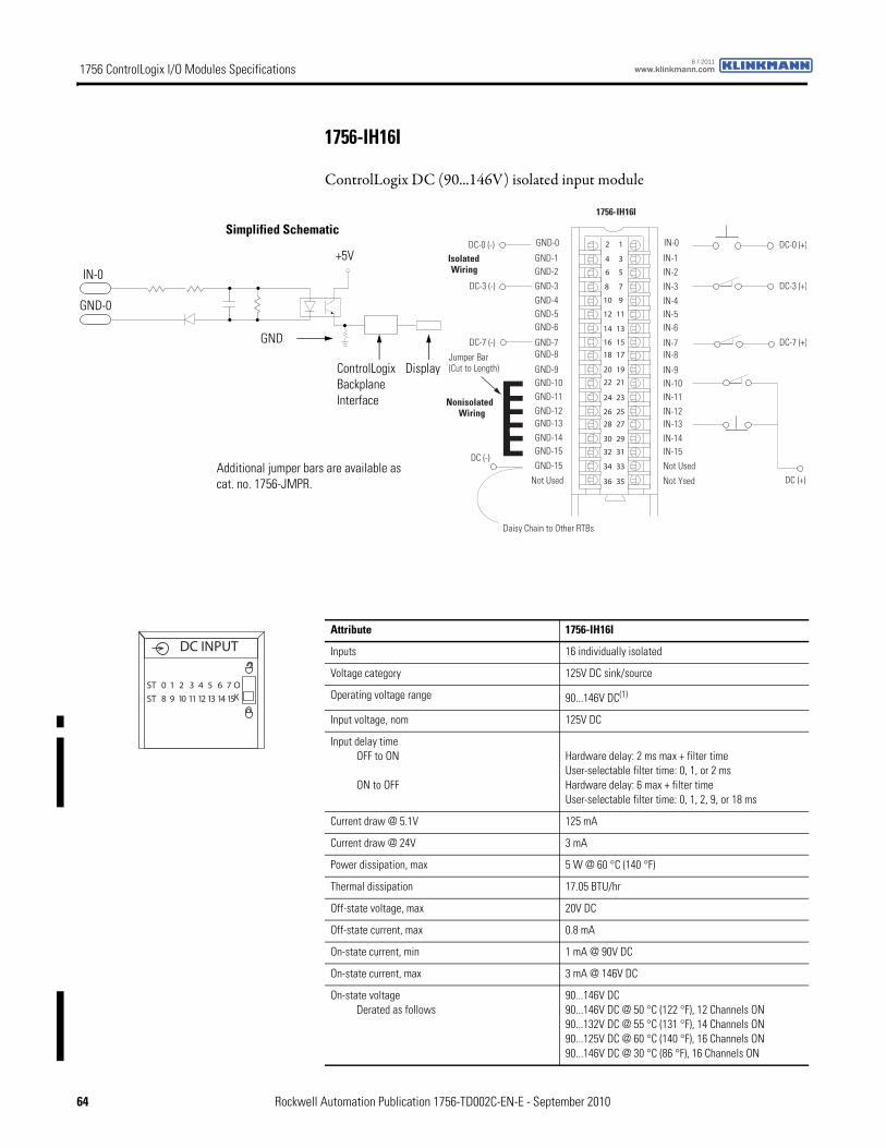
1756 ControlLogix I/O Modules Specifications www.klinkmann.com6 / 2011
1756-IH16I
ControlLogix DC (90...146V) isolated input module
12
34
56
78
910
1112
1314
1516
1718
1920
2122
2324
2526
2728
2930
3132
3334
3536
Nonisolated Wiring
IsolatedWiring
Daisy Chain to Other RTBs
1756-IH16I
DC (-)
Jumper Bar (Cut to Length)
)+( 7-CD)-( 7-CD
DC (+)
DC-0 (+)
DC-3 (+)
DC-0 (-)
DC-3 (-)
IN-0
IN-1IN-2
IN-3
IN-8
IN-4IN-5IN-6
IN-7
Not Ysed
IN-9IN-10IN-11
IN-12IN-13IN-14IN-15
Not Used
GND-0
GND-1GND-2
GND-3
GND-8
GND-4GND-5GND-6
GND-7
Not Used
GND-9GND-10GND-11GND-12GND-13GND-14GND-15
GND-15
ControlLogix Backplane Interface
Simplified Schematic
Display
GND-0
IN-0
GND
+5V
Additional jumper bars are available as cat. no. 1756-JMPR.
Attribute 1756-IH16I
Inputs 16 individually isolated
Voltage category 125V DC sink/source
Operating voltage range 90...146V DC(1)
Input voltage, nom 125V DC
Input delay timeOFF to ON
ON to OFF
Hardware delay: 2 ms max + filter timeUser-selectable filter time: 0, 1, or 2 msHardware delay: 6 max + filter timeUser-selectable filter time: 0, 1, 2, 9, or 18 ms
Current draw @ 5.1V 125 mA
Current draw @ 24V 3 mA
Power dissipation, max 5 W @ 60 °C (140 °F)
Thermal dissipation 17.05 BTU/hr
Off-state voltage, max 20V DC
Off-state current, max 0.8 mA
On-state current, min 1 mA @ 90V DC
On-state current, max 3 mA @ 146V DC
On-state voltageDerated as follows
90...146V DC90...146V DC @ 50 °C (122 °F), 12 Channels ON90...132V DC @ 55 °C (131 °F), 14 Channels ON90...125V DC @ 60 °C (140 °F), 16 Channels ON90...146V DC @ 30 °C (86 °F), 16 Channels ON
DC INPUT
ST 0 1 2 3 4 5 6 7
ST 8 9 10 11 12 13 14 15
OK
64 Rockwell Automation Publication 1756-TD002C-EN-E - September 2010
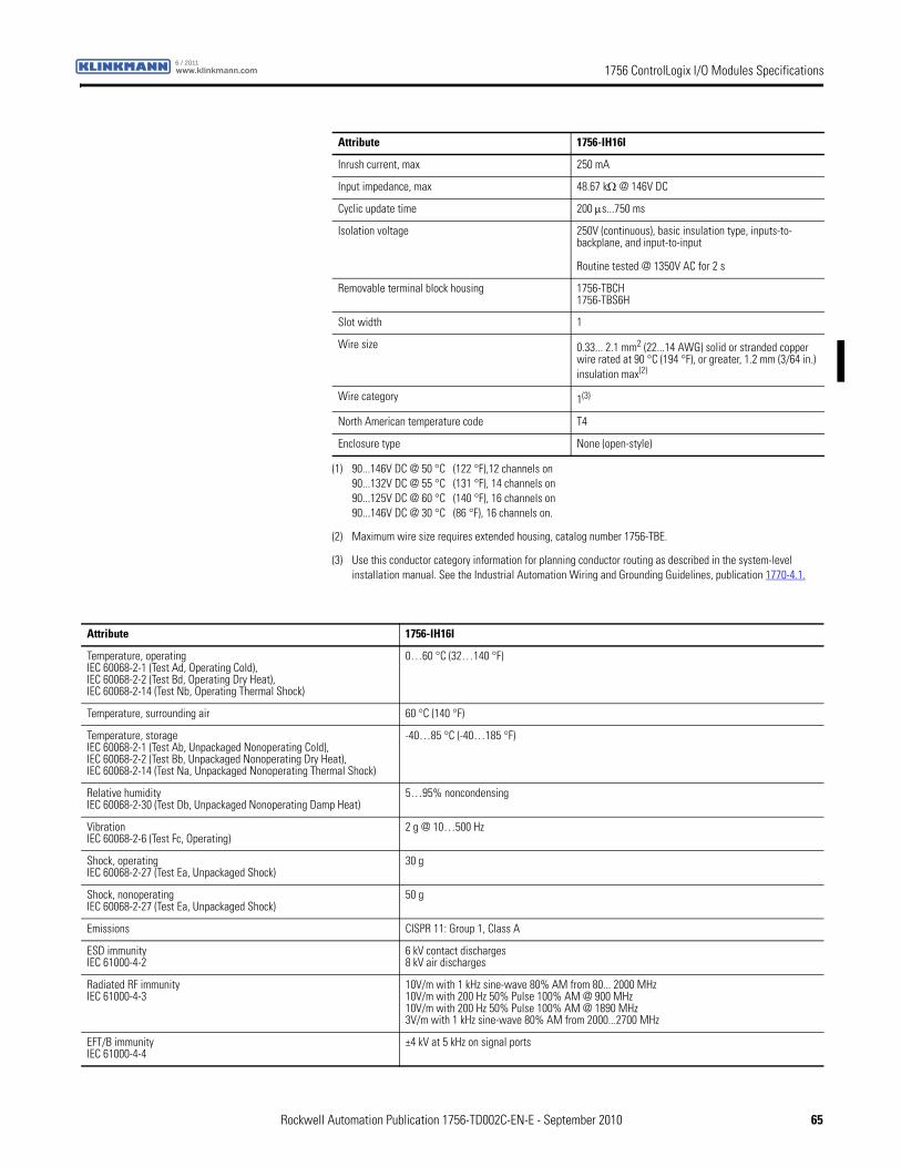
1756 ControlLogix I/O Modules Specificationswww.klinkmann.com6 / 2011
Inrush current, max 250 mA
Input impedance, max 48.67 kΩ @ 146V DC
Cyclic update time 200 μs...750 ms
Isolation voltage 250V (continuous), basic insulation type, inputs-to-backplane, and input-to-input
Routine tested @ 1350V AC for 2 s
Removable terminal block housing 1756-TBCH1756-TBS6H
Slot width 1
Wire size 0.33... 2.1 mm2 (22...14 AWG) solid or stranded copper wire rated at 90 °C (194 °F), or greater, 1.2 mm (3/64 in.) insulation max(2)
Wire category 1(3)
North American temperature code T4
Enclosure type None (open-style)
(1) 90...146V DC @ 50 °C (122 °F),12 channels on90...132V DC @ 55 °C (131 °F), 14 channels on90...125V DC @ 60 °C (140 °F), 16 channels on90...146V DC @ 30 °C (86 °F), 16 channels on.
(2) Maximum wire size requires extended housing, catalog number 1756-TBE.
(3) Use this conductor category information for planning conductor routing as described in the system-level installation manual. See the Industrial Automation Wiring and Grounding Guidelines, publication 1770-4.1.
Attribute 1756-IH16I
Attribute 1756-IH16I
Temperature, operatingIEC 60068-2-1 (Test Ad, Operating Cold),IEC 60068-2-2 (Test Bd, Operating Dry Heat),IEC 60068-2-14 (Test Nb, Operating Thermal Shock)
0…60 °C (32…140 °F)
Temperature, surrounding air 60 °C (140 °F)
Temperature, storageIEC 60068-2-1 (Test Ab, Unpackaged Nonoperating Cold),IEC 60068-2-2 (Test Bb, Unpackaged Nonoperating Dry Heat),IEC 60068-2-14 (Test Na, Unpackaged Nonoperating Thermal Shock)
-40…85 °C (-40…185 °F)
Relative humidityIEC 60068-2-30 (Test Db, Unpackaged Nonoperating Damp Heat)
5…95% noncondensing
VibrationIEC 60068-2-6 (Test Fc, Operating)
2 g @ 10…500 Hz
Shock, operatingIEC 60068-2-27 (Test Ea, Unpackaged Shock)
30 g
Shock, nonoperatingIEC 60068-2-27 (Test Ea, Unpackaged Shock)
50 g
Emissions CISPR 11: Group 1, Class A
ESD immunityIEC 61000-4-2
6 kV contact discharges8 kV air discharges
Radiated RF immunityIEC 61000-4-3
10V/m with 1 kHz sine-wave 80% AM from 80... 2000 MHz10V/m with 200 Hz 50% Pulse 100% AM @ 900 MHz10V/m with 200 Hz 50% Pulse 100% AM @ 1890 MHz3V/m with 1 kHz sine-wave 80% AM from 2000...2700 MHz
EFT/B immunityIEC 61000-4-4
±4 kV at 5 kHz on signal ports
Rockwell Automation Publication 1756-TD002C-EN-E - September 2010 65
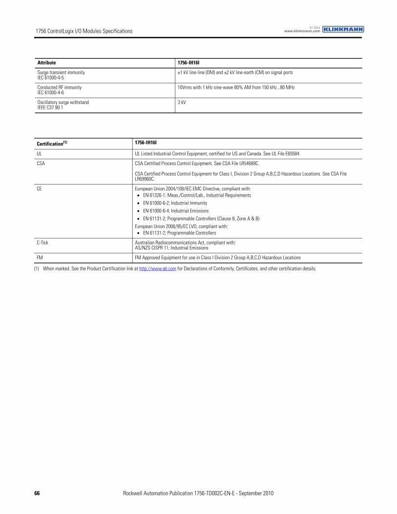
1756 ControlLogix I/O Modules Specifications www.klinkmann.com6 / 2011
Surge transient immunityIEC 61000-4-5
±1 kV line-line (DM) and ±2 kV line-earth (CM) on signal ports
Conducted RF immunityIEC 61000-4-6
10Vrms with 1 kHz sine-wave 80% AM from 150 kHz...80 MHz
Oscillatory surge withstandIEEE C37.90.1
3 kV
Attribute 1756-IH16I
Certification(1) 1756-IH16I
UL UL Listed Industrial Control Equipment, certified for US and Canada. See UL File E65584.
CSA CSA Certified Process Control Equipment. See CSA File LR54689C.
CSA Certified Process Control Equipment for Class I, Division 2 Group A,B,C,D Hazardous Locations. See CSA File LR69960C.
CE European Union 2004/108/IEC EMC Directive, compliant with:• EN 61326-1; Meas./Control/Lab., Industrial Requirements
• EN 61000-6-2; Industrial Immunity
• EN 61000-6-4; Industrial Emissions
• EN 61131-2; Programmable Controllers (Clause 8, Zone A & B)
European Union 2006/95/EC LVD, compliant with:• EN 61131-2; Programmable Controllers
C-Tick Australian Radiocommunications Act, compliant with:AS/NZS CISPR 11; Industrial Emissions
FM FM Approved Equipment for use in Class I Division 2 Group A,B,C,D Hazardous Locations
(1) When marked. See the Product Certification link at http://www.ab.com for Declarations of Conformity, Certificates, and other certification details.
66 Rockwell Automation Publication 1756-TD002C-EN-E - September 2010
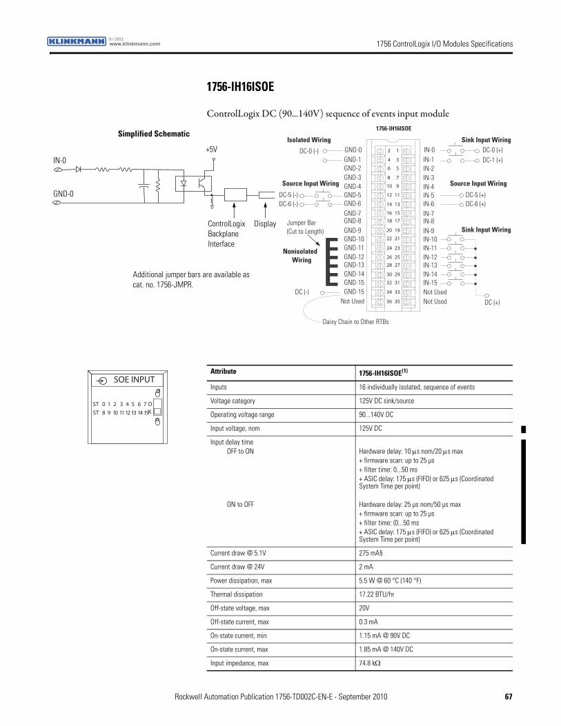
1756 ControlLogix I/O Modules Specificationswww.klinkmann.com6 / 2011
1756-IH16ISOE
ControlLogix DC (90...140V) sequence of events input module
12
34
56
78
910
1112
1314
1516
1718
1920
2122
2324
2526
2728
2930
3132
3334
3536
Nonisolated Wiring
Isolated Wiring
Daisy Chain to Other RTBs
DC (-)
Jumper Bar (Cut to Length)
)+( 6-CD)-( 6-CD
DC (+)
DC-0 (+)DC-1 (+)
DC-0 (-)
DC-5 (-)
IN-0IN-1IN-2IN-3
IN-8
IN-4IN-5IN-6IN-7
Not Used
IN-9IN-10IN-11IN-12IN-13IN-14IN-15Not Used
GND-0GND-1GND-2GND-3
GND-8
GND-4GND-5GND-6GND-7
Not Used
GND-9GND-10GND-11GND-12GND-13GND-14GND-15GND-15
DC-5 (+)
Sink Input Wiring
Source Input WiringSource Input Wiring
Sink Input Wiring
1756-IH16ISOESimplified Schematic
ControlLogix Backplane Interface
IN-0
GND-0
Display
+5V
Additional jumper bars are available as cat. no. 1756-JMPR.
Attribute 1756-IH16ISOE(1)
Inputs 16 individually isolated, sequence of events
Voltage category 125V DC sink/source
Operating voltage range 90...140V DC
Input voltage, nom 125V DC
Input delay timeOFF to ON
ON to OFF
Hardware delay: 10 μs nom/20 μs max+ firmware scan: up to 25 µs+ filter time: 0...50 ms+ ASIC delay: 175 μs (FIFO) or 625 μs (Coordinated System Time per point)
Hardware delay: 25 µs nom/50 µs max+ firmware scan: up to 25 µs+ filter time: (0...50 ms+ ASIC delay: 175 μs (FIFO) or 625 μs (Coordinated System Time per point)
Current draw @ 5.1V 275 mA§
Current draw @ 24V 2 mA
Power dissipation, max 5.5 W @ 60 °C (140 °F)
Thermal dissipation 17.22 BTU/hr
Off-state voltage, max 20V
Off-state current, max 0.3 mA
On-state current, min 1.15 mA @ 90V DC
On-state current, max 1.85 mA @ 140V DC
Input impedance, max 74.8 kΩ
SOE INPUT
ST 0 1 2 3 4 5 6 7
ST 8 9 10 11 12 13 14 15
OK
Rockwell Automation Publication 1756-TD002C-EN-E - September 2010 67
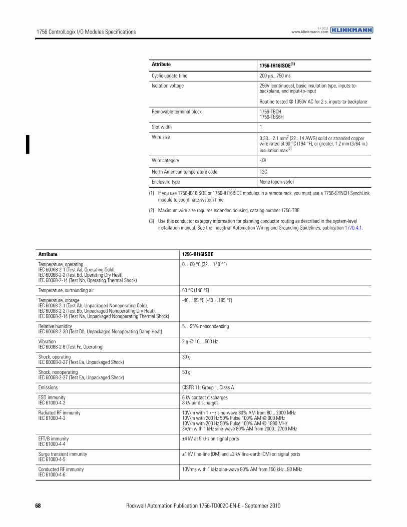
1756 ControlLogix I/O Modules Specifications www.klinkmann.com6 / 2011
Cyclic update time 200 μs...750 ms
Isolation voltage 250V (continuous), basic insulation type, inputs-to-backplane, and input-to-input
Routine tested @ 1350V AC for 2 s, inputs-to-backplane
Removable terminal block 1756-TBCH1756-TBS6H
Slot width 1
Wire size 0.33... 2.1 mm2 (22...14 AWG) solid or stranded copper wire rated at 90 °C (194 °F), or greater, 1.2 mm (3/64 in.) insulation max(2)
Wire category 1(3)
North American temperature code T3C
Enclosure type None (open-style)
(1) If you use 1756-IB16ISOE or 1756-IH16ISOE modules in a remote rack, you must use a 1756-SYNCH SynchLink module to coordinate system time.
(2) Maximum wire size requires extended housing, catalog number 1756-TBE.
(3) Use this conductor category information for planning conductor routing as described in the system-level installation manual. See the Industrial Automation Wiring and Grounding Guidelines, publication 1770-4.1.
Attribute 1756-IH16ISOE(1)
Attribute 1756-IH16ISOE
Temperature, operatingIEC 60068-2-1 (Test Ad, Operating Cold),IEC 60068-2-2 (Test Bd, Operating Dry Heat),IEC 60068-2-14 (Test Nb, Operating Thermal Shock)
0…60 °C (32…140 °F)
Temperature, surrounding air 60 °C (140 °F)
Temperature, storageIEC 60068-2-1 (Test Ab, Unpackaged Nonoperating Cold),IEC 60068-2-2 (Test Bb, Unpackaged Nonoperating Dry Heat),IEC 60068-2-14 (Test Na, Unpackaged Nonoperating Thermal Shock)
-40…85 °C (-40…185 °F)
Relative humidityIEC 60068-2-30 (Test Db, Unpackaged Nonoperating Damp Heat)
5…95% noncondensing
VibrationIEC 60068-2-6 (Test Fc, Operating)
2 g @ 10…500 Hz
Shock, operatingIEC 60068-2-27 (Test Ea, Unpackaged Shock)
30 g
Shock, nonoperatingIEC 60068-2-27 (Test Ea, Unpackaged Shock)
50 g
Emissions CISPR 11: Group 1, Class A
ESD immunityIEC 61000-4-2
6 kV contact discharges8 kV air discharges
Radiated RF immunityIEC 61000-4-3
10V/m with 1 kHz sine-wave 80% AM from 80... 2000 MHz10V/m with 200 Hz 50% Pulse 100% AM @ 900 MHz10V/m with 200 Hz 50% Pulse 100% AM @ 1890 MHz3V/m with 1 kHz sine-wave 80% AM from 2000...2700 MHz
EFT/B immunityIEC 61000-4-4
±4 kV at 5 kHz on signal ports
Surge transient immunityIEC 61000-4-5
±1 kV line-line (DM) and ±2 kV line-earth (CM) on signal ports
Conducted RF immunityIEC 61000-4-6
10Vrms with 1 kHz sine-wave 80% AM from 150 kHz...80 MHz
68 Rockwell Automation Publication 1756-TD002C-EN-E - September 2010
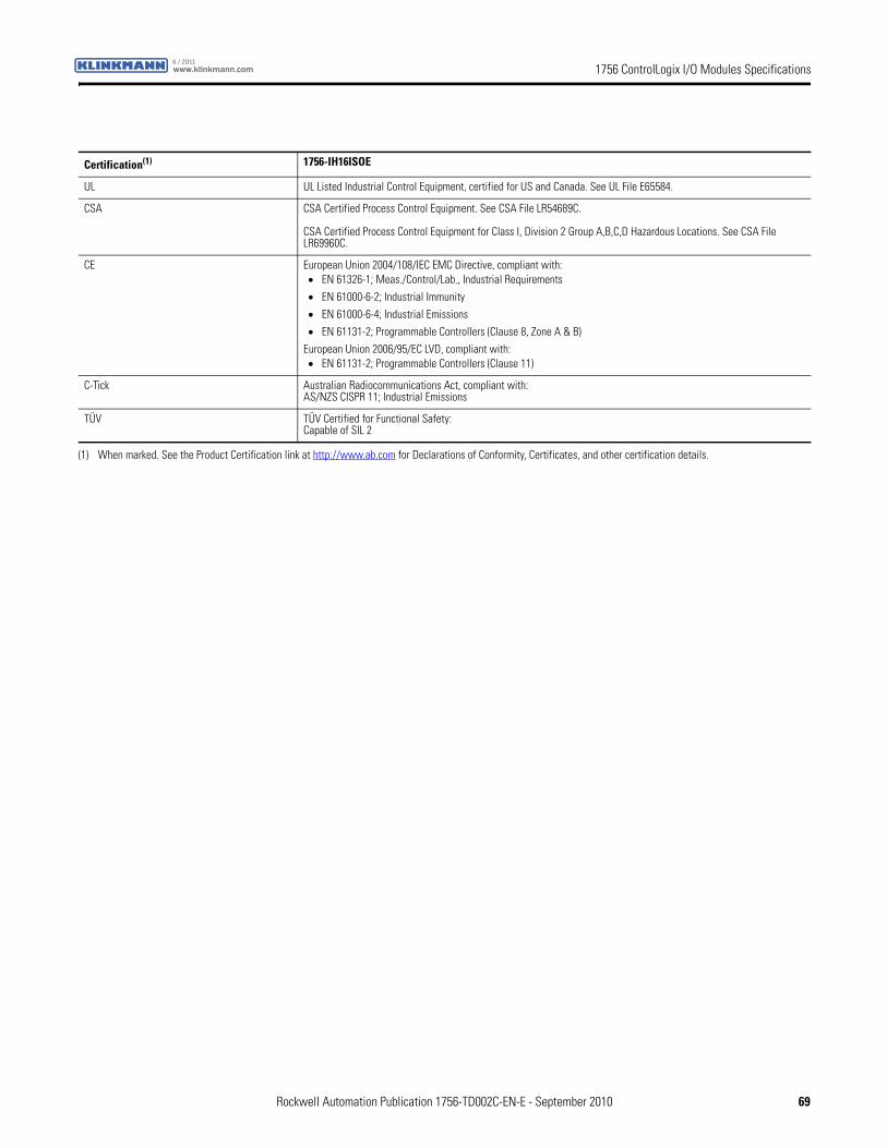
1756 ControlLogix I/O Modules Specificationswww.klinkmann.com6 / 2011
Certification(1) 1756-IH16ISOE
UL UL Listed Industrial Control Equipment, certified for US and Canada. See UL File E65584.
CSA CSA Certified Process Control Equipment. See CSA File LR54689C.
CSA Certified Process Control Equipment for Class I, Division 2 Group A,B,C,D Hazardous Locations. See CSA File LR69960C.
CE European Union 2004/108/IEC EMC Directive, compliant with:• EN 61326-1; Meas./Control/Lab., Industrial Requirements
• EN 61000-6-2; Industrial Immunity
• EN 61000-6-4; Industrial Emissions
• EN 61131-2; Programmable Controllers (Clause 8, Zone A & B)
European Union 2006/95/EC LVD, compliant with:• EN 61131-2; Programmable Controllers (Clause 11)
C-Tick Australian Radiocommunications Act, compliant with:AS/NZS CISPR 11; Industrial Emissions
TÜV TÜV Certified for Functional Safety:Capable of SIL 2
(1) When marked. See the Product Certification link at http://www.ab.com for Declarations of Conformity, Certificates, and other certification details.
Rockwell Automation Publication 1756-TD002C-EN-E - September 2010 69
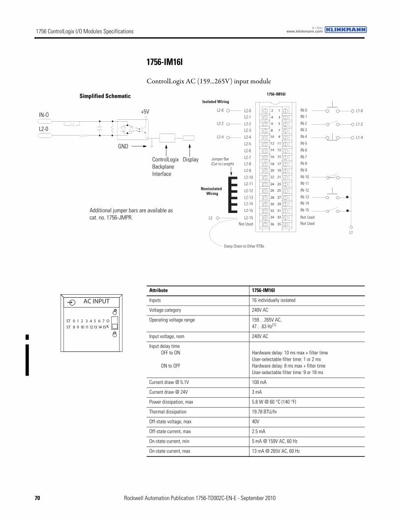
1756 ControlLogix I/O Modules Specifications www.klinkmann.com6 / 2011
1756-IM16I
ControlLogix AC (159...265V) input module
12
34
56
78
910
1112
1314
1516
1718
1920
2122
2324
2526
2728
2930
3132
3334
3536
Nonisolated Wiring
Isolated Wiring
Daisy Chain to Other RTBs
L2-0
1756-IM16I
L2-0L2-1
L2-2
L2-3
L2-8
L2-4
L2-5
L2-6
L2-7
Not Used
L2-9
L2-10
L2-11
L2-12
L2-13L2-14
L2-15
L2-15
IN-0IN-1
IN-2
IN-3
IN-8
IN-4
IN-5
IN-6
IN-7
Not Used
IN-9
IN-10
IN-11
IN-12
IN-13IN-14
IN-15
Not Used
L2-2
L2-4
L2
L1
L1-0
L1-2
L1-4
Jumper Bar (Cut to Length)
ControlLogix Backplane Interface
Simplified Schematic
Display
+5V
L2-0
IN-O
GND
Additional jumper bars are available as cat. no. 1756-JMPR.
Attribute 1756-IM16I
Inputs 16 individually isolated
Voltage category 240V AC
Operating voltage range 159…265V AC,47…63 Hz(1)
Input voltage, nom 240V AC
Input delay timeOFF to ON
ON to OFF
Hardware delay: 10 ms max + filter timeUser-selectable filter time: 1 or 2 msHardware delay: 8 ms max + filter timeUser-selectable filter time: 9 or 18 ms
Current draw @ 5.1V 100 mA
Current draw @ 24V 3 mA
Power dissipation, max 5.8 W @ 60 °C (140 °F)
Thermal dissipation 19.78 BTU/hr
Off-state voltage, max 40V
Off-state current, max 2.5 mA
On-state current, min 5 mA @ 159V AC, 60 Hz
On-state current, max 13 mA @ 265V AC, 60 Hz
ST 0 1 2 3 4 5 6 7
ST 8 9 10 11 12 13 14 15
OK
AC INPUT
70 Rockwell Automation Publication 1756-TD002C-EN-E - September 2010
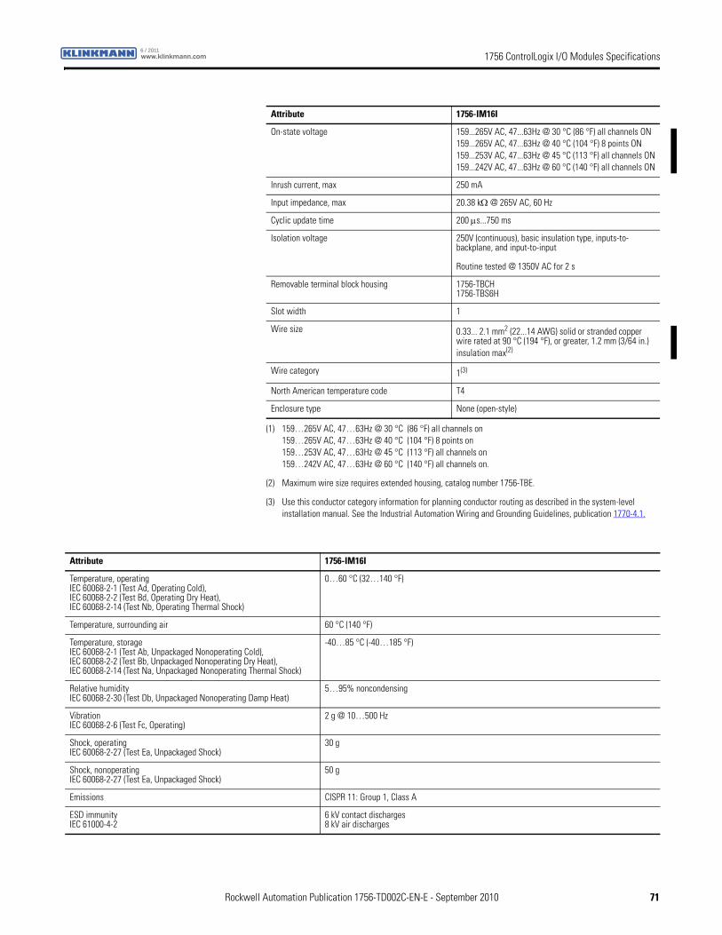
1756 ControlLogix I/O Modules Specificationswww.klinkmann.com6 / 2011
On-state voltage 159...265V AC, 47...63Hz @ 30 °C (86 °F) all channels ON159...265V AC, 47...63Hz @ 40 °C (104 °F) 8 points ON159...253V AC, 47...63Hz @ 45 °C (113 °F) all channels ON159...242V AC, 47...63Hz @ 60 °C (140 °F) all channels ON
Inrush current, max 250 mA
Input impedance, max 20.38 kΩ @ 265V AC, 60 Hz
Cyclic update time 200 μs...750 ms
Isolation voltage 250V (continuous), basic insulation type, inputs-to-backplane, and input-to-input
Routine tested @ 1350V AC for 2 s
Removable terminal block housing 1756-TBCH1756-TBS6H
Slot width 1
Wire size 0.33... 2.1 mm2 (22...14 AWG) solid or stranded copper wire rated at 90 °C (194 °F), or greater, 1.2 mm (3/64 in.) insulation max(2)
Wire category 1(3)
North American temperature code T4
Enclosure type None (open-style)
(1) 159…265V AC, 47…63Hz @ 30 °C (86 °F) all channels on159…265V AC, 47…63Hz @ 40 °C (104 °F) 8 points on159…253V AC, 47…63Hz @ 45 °C (113 °F) all channels on159…242V AC, 47…63Hz @ 60 °C (140 °F) all channels on.
(2) Maximum wire size requires extended housing, catalog number 1756-TBE.
(3) Use this conductor category information for planning conductor routing as described in the system-level installation manual. See the Industrial Automation Wiring and Grounding Guidelines, publication 1770-4.1.
Attribute 1756-IM16I
Attribute 1756-IM16I
Temperature, operatingIEC 60068-2-1 (Test Ad, Operating Cold),IEC 60068-2-2 (Test Bd, Operating Dry Heat),IEC 60068-2-14 (Test Nb, Operating Thermal Shock)
0…60 °C (32…140 °F)
Temperature, surrounding air 60 °C (140 °F)
Temperature, storageIEC 60068-2-1 (Test Ab, Unpackaged Nonoperating Cold),IEC 60068-2-2 (Test Bb, Unpackaged Nonoperating Dry Heat),IEC 60068-2-14 (Test Na, Unpackaged Nonoperating Thermal Shock)
-40…85 °C (-40…185 °F)
Relative humidityIEC 60068-2-30 (Test Db, Unpackaged Nonoperating Damp Heat)
5…95% noncondensing
VibrationIEC 60068-2-6 (Test Fc, Operating)
2 g @ 10…500 Hz
Shock, operatingIEC 60068-2-27 (Test Ea, Unpackaged Shock)
30 g
Shock, nonoperatingIEC 60068-2-27 (Test Ea, Unpackaged Shock)
50 g
Emissions CISPR 11: Group 1, Class A
ESD immunityIEC 61000-4-2
6 kV contact discharges8 kV air discharges
Rockwell Automation Publication 1756-TD002C-EN-E - September 2010 71
1756 ControlLogix I/O Modules Specifications www.klinkmann.com6 / 2011
Radiated RF immunityIEC 61000-4-3
10V/m with 1 kHz sine-wave 80% AM from 80... 2000 MHz10V/m with 200 Hz 50% Pulse 100% AM @ 900 MHz10V/m with 200 Hz 50% Pulse 100% AM @ 1890 MHz3V/m with 1 kHz sine-wave 80% AM from 2000...2700 MHz
EFT/B immunityIEC 61000-4-4
±4 kV at 5 kHz on signal ports
Surge transient immunityIEC 61000-4-5
±1 kV line-line (DM) and ±2 kV line-earth (CM) on signal ports
Conducted RF immunityIEC 61000-4-6
10Vrms with 1 kHz sine-wave 80% AM from 150 kHz...80 MHz
Attribute 1756-IM16I
Certification(1) 1756-IM16I
FM FM Approved Equipment for use in Class I Division 2 Group A,B,C,D Hazardous Locations
CSA CSA Certified Process Control Equipment. See CSA File LR54689C.
CSA Certified Process Control Equipment for Class I, Division 2 Group A,B,C,D Hazardous Locations. See CSA File LR69960C.
CE European Union 2004/108/IEC EMC Directive, compliant with:• EN 61326-1; Meas./Control/Lab., Industrial Requirements
• EN 61000-6-2; Industrial Immunity
• EN 61000-6-4; Industrial Emissions
• EN 61131-2; Programmable Controllers (Clause 8, Zone A & B)
European Union 2006/95/EC LVD, compliant with:• EN 61131-2; Programmable Controllers
C-Tick Australian Radiocommunications Act, compliant with:AS/NZS CISPR 11; Industrial Emissions
FM FM Approved Equipment for use in Class I Division 2 Group A,B,C,D Hazardous Locations
(1) When marked. See the Product Certification link at http://www.ab.com for Declarations of Conformity, Certificates, and other certification details.
72 Rockwell Automation Publication 1756-TD002C-EN-E - September 2010
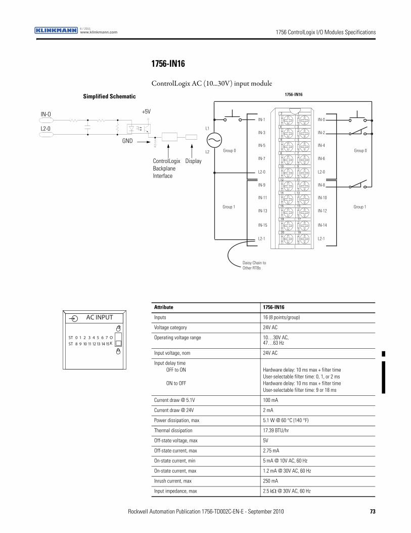
1756 ControlLogix I/O Modules Specificationswww.klinkmann.com6 / 2011
1756-IN16
ControlLogix AC (10...30V) input module
12
34
56
78
910
1112
1314
1516
1718
1920
Daisy Chain to Other RTBs
1756-IN16
Group 0Group 0
Group 1Group 1
IN-1
IN-3
IN-5
IN-7
L2-0
IN-9
IN-11
IN-13
IN-15
L2-1
IN-0
IN-2
IN-4
IN-6
L2-0
IN-8
IN-10
IN-12
IN-14
L2-1
L2
L1
ControlLogix Backplane Interface
Simplified Schematic
Display
+5V
L2-0
IN-O
GND
Attribute 1756-IN16
Inputs 16 (8 points/group)
Voltage category 24V AC
Operating voltage range 10…30V AC,47…63 Hz
Input voltage, nom 24V AC
Input delay timeOFF to ON
ON to OFF
Hardware delay: 10 ms max + filter timeUser-selectable filter time: 0, 1, or 2 msHardware delay: 10 ms max + filter timeUser-selectable filter time: 9 or 18 ms
Current draw @ 5.1V 100 mA
Current draw @ 24V 2 mA
Power dissipation, max 5.1 W @ 60 °C (140 °F)
Thermal dissipation 17.39 BTU/hr
Off-state voltage, max 5V
Off-state current, max 2.75 mA
On-state current, min 5 mA @ 10V AC, 60 Hz
On-state current, max 1.2 mA @ 30V AC, 60 Hz
Inrush current, max 250 mA
Input impedance, max 2.5 kΩ @ 30V AC, 60 Hz
ST 0 1 2 3 4 5 6 7
ST 8 9 10 11 12 13 14 15
OK
AC INPUT
Rockwell Automation Publication 1756-TD002C-EN-E - September 2010 73
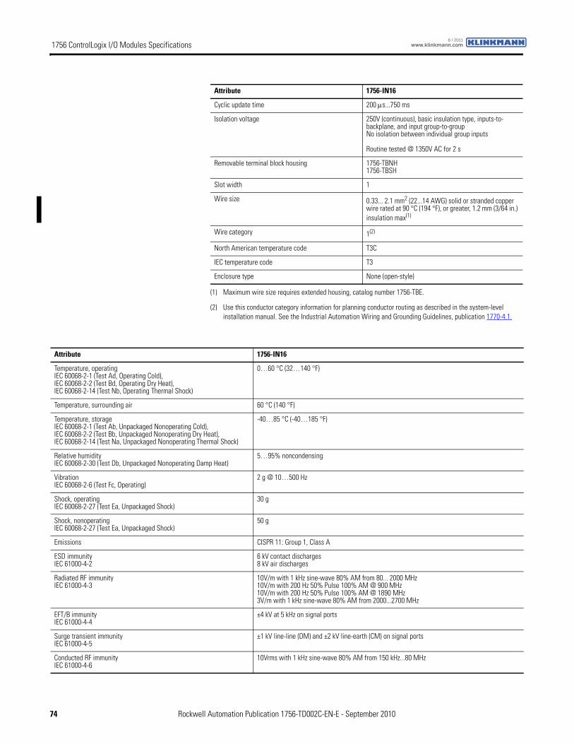
1756 ControlLogix I/O Modules Specifications www.klinkmann.com6 / 2011
Cyclic update time 200 μs...750 ms
Isolation voltage 250V (continuous), basic insulation type, inputs-to-backplane, and input group-to-groupNo isolation between individual group inputs
Routine tested @ 1350V AC for 2 s
Removable terminal block housing 1756-TBNH1756-TBSH
Slot width 1
Wire size 0.33... 2.1 mm2 (22...14 AWG) solid or stranded copper wire rated at 90 °C (194 °F), or greater, 1.2 mm (3/64 in.) insulation max(1)
Wire category 1(2)
North American temperature code T3C
IEC temperature code T3
Enclosure type None (open-style)
(1) Maximum wire size requires extended housing, catalog number 1756-TBE.
(2) Use this conductor category information for planning conductor routing as described in the system-level installation manual. See the Industrial Automation Wiring and Grounding Guidelines, publication 1770-4.1.
Attribute 1756-IN16
Attribute 1756-IN16
Temperature, operatingIEC 60068-2-1 (Test Ad, Operating Cold),IEC 60068-2-2 (Test Bd, Operating Dry Heat),IEC 60068-2-14 (Test Nb, Operating Thermal Shock)
0…60 °C (32…140 °F)
Temperature, surrounding air 60 °C (140 °F)
Temperature, storageIEC 60068-2-1 (Test Ab, Unpackaged Nonoperating Cold),IEC 60068-2-2 (Test Bb, Unpackaged Nonoperating Dry Heat),IEC 60068-2-14 (Test Na, Unpackaged Nonoperating Thermal Shock)
-40…85 °C (-40…185 °F)
Relative humidityIEC 60068-2-30 (Test Db, Unpackaged Nonoperating Damp Heat)
5…95% noncondensing
VibrationIEC 60068-2-6 (Test Fc, Operating)
2 g @ 10…500 Hz
Shock, operatingIEC 60068-2-27 (Test Ea, Unpackaged Shock)
30 g
Shock, nonoperatingIEC 60068-2-27 (Test Ea, Unpackaged Shock)
50 g
Emissions CISPR 11: Group 1, Class A
ESD immunityIEC 61000-4-2
6 kV contact discharges8 kV air discharges
Radiated RF immunityIEC 61000-4-3
10V/m with 1 kHz sine-wave 80% AM from 80... 2000 MHz10V/m with 200 Hz 50% Pulse 100% AM @ 900 MHz10V/m with 200 Hz 50% Pulse 100% AM @ 1890 MHz3V/m with 1 kHz sine-wave 80% AM from 2000...2700 MHz
EFT/B immunityIEC 61000-4-4
±4 kV at 5 kHz on signal ports
Surge transient immunityIEC 61000-4-5
±1 kV line-line (DM) and ±2 kV line-earth (CM) on signal ports
Conducted RF immunityIEC 61000-4-6
10Vrms with 1 kHz sine-wave 80% AM from 150 kHz...80 MHz
74 Rockwell Automation Publication 1756-TD002C-EN-E - September 2010

1756 ControlLogix I/O Modules Specificationswww.klinkmann.com6 / 2011
Certification(1) 1756-IN16
UL UL Listed Industrial Control Equipment, certified for US and Canada. See UL File E65584.
CSA CSA Certified Process Control Equipment. See CSA File LR54689C.
CSA Certified Process Control Equipment for Class I, Division 2 Group A,B,C,D Hazardous Locations. See CSA File LR69960C.
CE European Union 2004/108/IEC EMC Directive, compliant with:• EN 61326-1; Meas./Control/Lab., Industrial Requirements
• EN 61000-6-2; Industrial Immunity
• EN 61000-6-4; Industrial Emissions
• EN 61131-2; Programmable Controllers (Clause 8, Zone A & B)
European Union 2006/95/EC LVD, compliant with:• EN 61131-2; Programmable Controllers (Clause 11)
C-Tick Australian Radiocommunications Act, compliant with:AS/NZS CISPR 11; Industrial Emissions
Ex European Union 94/9/EC ATEX Directive, compliant with:• EN 60079-15; Potentially Explosive Atmospheres, Protection "n"
• EN 60079-0; General Requirements II 3 G Ex nA IIC T3 X
FM FM Approved Equipment for use in Class I Division 2 Group A,B,C,D Hazardous Locations
(1) When marked. See the Product Certification link at http://www.ab.com for Declarations of Conformity, Certificates, and other certification details.
Rockwell Automation Publication 1756-TD002C-EN-E - September 2010 75
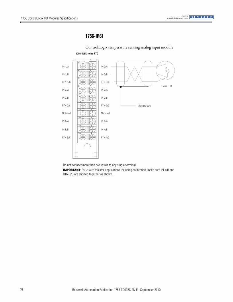
1756 ControlLogix I/O Modules Specifications www.klinkmann.com6 / 2011
1756-IR6I
ControlLogix temperature sensing analog input module
12
34
56
78
910
1112
1314
1516
1718
1920
1756-IR6I 3-wire RTD
3-wire RTD
Shield Ground
IN-1/A
IN-1/B
RTN-1/C
IN-3/A
IN-3/B
RTN-3/C
Not used
IN-5/A
IN-5/B
RTN-5/C
IN-0/A
IN-0/B
RTN-0/C
IN-2/A
IN-2/B
RTN-2/C
Not used
IN-4/A
IN-4/B
RTN-4/C
Do not connect more than two wires to any single terminal.IMPORTANT: For 2-wire resistor applications including calibration, make sure IN-x/B and RTN-x/C are shorted together as shown.
76 Rockwell Automation Publication 1756-TD002C-EN-E - September 2010
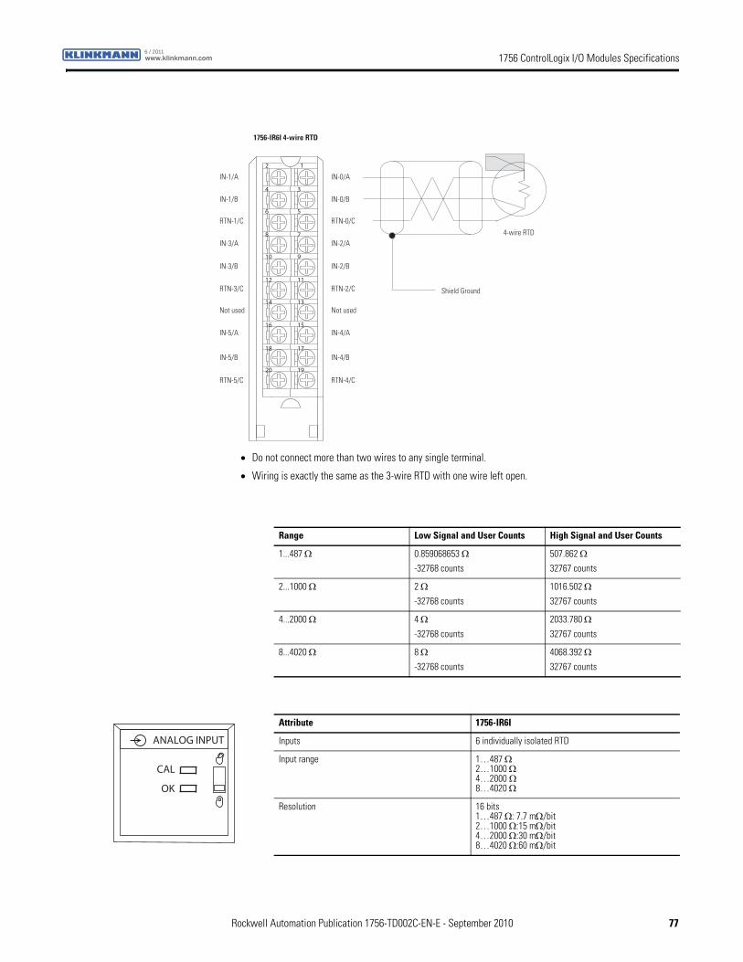
1756 ControlLogix I/O Modules Specificationswww.klinkmann.com6 / 2011
12
34
56
78
910
1112
1314
1516
1718
1920
1756-IR6I 4-wire RTD
4-wire RTD
Shield Ground
IN-1/A
IN-1/B
RTN-1/C
IN-3/A
IN-3/B
RTN-3/C
Not used
IN-5/A
IN-5/B
RTN-5/C
IN-0/A
IN-0/B
RTN-0/C
IN-2/A
IN-2/B
RTN-2/C
Not used
IN-4/A
IN-4/B
RTN-4/C
• Do not connect more than two wires to any single terminal.
• Wiring is exactly the same as the 3-wire RTD with one wire left open.
Range Low Signal and User Counts High Signal and User Counts
1...487 Ω 0.859068653 Ω-32768 counts
507.862 Ω32767 counts
2...1000 Ω 2 Ω-32768 counts
1016.502 Ω32767 counts
4...2000 Ω 4 Ω-32768 counts
2033.780 Ω32767 counts
8...4020 Ω 8 Ω-32768 counts
4068.392 Ω32767 counts
Attribute 1756-IR6I
Inputs 6 individually isolated RTD
Input range 1…487 Ω2…1000 Ω4…2000 Ω8…4020 Ω
Resolution 16 bits1…487 Ω: 7.7 mΩ/bit2…1000 Ω:15 mΩ/bit4…2000 Ω:30 mΩ/bit8…4020 Ω:60 mΩ/bit
ANALOG INPUT
CAL
OK
Rockwell Automation Publication 1756-TD002C-EN-E - September 2010 77
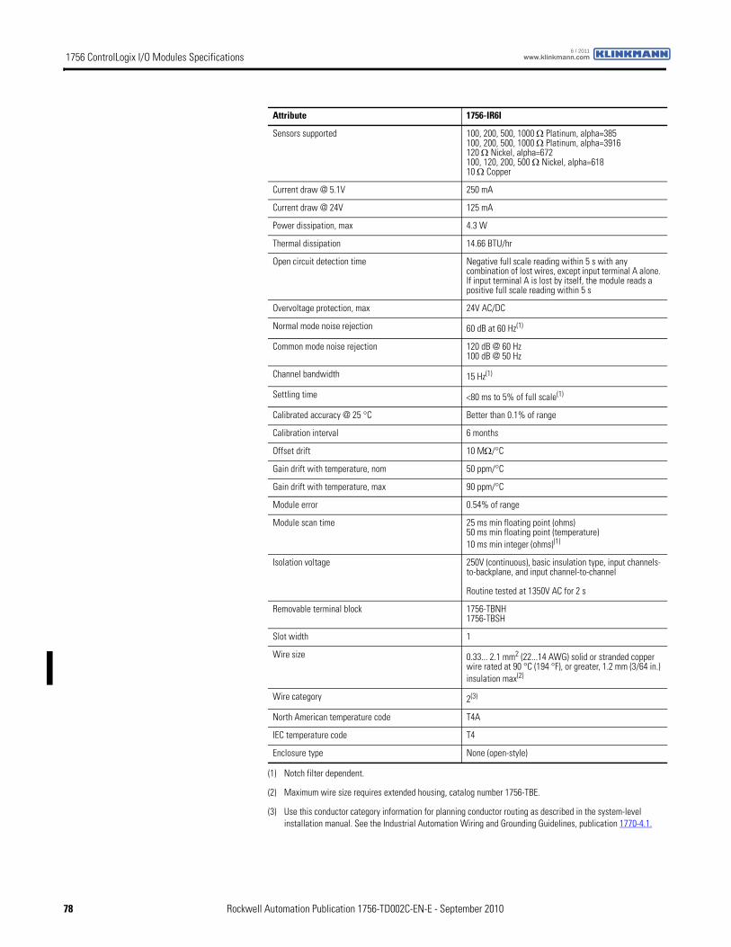
1756 ControlLogix I/O Modules Specifications www.klinkmann.com6 / 2011
Sensors supported 100, 200, 500, 1000 Ω Platinum, alpha=385100, 200, 500, 1000 Ω Platinum, alpha=3916120 Ω Nickel, alpha=672100, 120, 200, 500 Ω Nickel, alpha=61810 Ω Copper
Current draw @ 5.1V 250 mA
Current draw @ 24V 125 mA
Power dissipation, max 4.3 W
Thermal dissipation 14.66 BTU/hr
Open circuit detection time Negative full scale reading within 5 s with any combination of lost wires, except input terminal A alone. If input terminal A is lost by itself, the module reads a positive full scale reading within 5 s
Overvoltage protection, max 24V AC/DC
Normal mode noise rejection 60 dB at 60 Hz(1)
Common mode noise rejection 120 dB @ 60 Hz100 dB @ 50 Hz
Channel bandwidth 15 Hz(1)
Settling time <80 ms to 5% of full scale(1)
Calibrated accuracy @ 25 °C Better than 0.1% of range
Calibration interval 6 months
Offset drift 10 MΩ/°C
Gain drift with temperature, nom 50 ppm/°C
Gain drift with temperature, max 90 ppm/°C
Module error 0.54% of range
Module scan time 25 ms min floating point (ohms)50 ms min floating point (temperature)10 ms min integer (ohms)(1)
Isolation voltage 250V (continuous), basic insulation type, input channels-to-backplane, and input channel-to-channel
Routine tested at 1350V AC for 2 s
Removable terminal block 1756-TBNH1756-TBSH
Slot width 1
Wire size 0.33... 2.1 mm2 (22...14 AWG) solid or stranded copper wire rated at 90 °C (194 °F), or greater, 1.2 mm (3/64 in.) insulation max(2)
Wire category 2(3)
North American temperature code T4A
IEC temperature code T4
Enclosure type None (open-style)
(1) Notch filter dependent.
(2) Maximum wire size requires extended housing, catalog number 1756-TBE.
(3) Use this conductor category information for planning conductor routing as described in the system-level installation manual. See the Industrial Automation Wiring and Grounding Guidelines, publication 1770-4.1.
Attribute 1756-IR6I
78 Rockwell Automation Publication 1756-TD002C-EN-E - September 2010
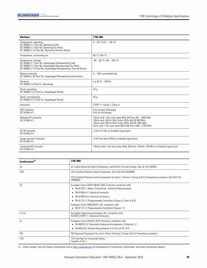
1756 ControlLogix I/O Modules Specificationswww.klinkmann.com6 / 2011
Attribute 1756-IR6I
Temperature, operatingIEC 60068-2-1 (Test Ad, Operating Cold),IEC 60068-2-2 (Test Bd, Operating Dry Heat),IEC 60068-2-14 (Test Nb, Operating Thermal Shock)
0…60 °C (32…140 °F)
Temperature, surrounding air 60 °C (140 °F)
Temperature, storageIEC 60068-2-1 (Test Ab, Unpackaged Nonoperating Cold),IEC 60068-2-2 (Test Bb, Unpackaged Nonoperating Dry Heat),IEC 60068-2-14 (Test Na, Unpackaged Nonoperating Thermal Shock)
-40…85 °C (-40…185 °F)
Relative humidityIEC 60068-2-30 (Test Db, Unpackaged Nonoperating Damp Heat)
5…95% noncondensing
VibrationIEC 60068-2-6 (Test Fc, Operating)
2 g @ 10…500 Hz
Shock, operatingIEC 60068-2-27 (Test Ea, Unpackaged Shock)
30 g
Shock, nonoperatingIEC 60068-2-27 (Test Ea, Unpackaged Shock)
50 g
Emissions CISPR 11: Group 1, Class A
ESD immunityIEC 61000-4-2
6 kV contact discharges8 kV air discharges
Radiated RF immunityIEC 61000-4-3
10V/m with 1 kHz sine-wave 80% AM from 80... 2000 MHz10V/m with 200 Hz 50% Pulse 100% AM @ 900 MHz10V/m with 200 Hz 50% Pulse 100% AM @ 1890 MHz3V/m with 1 kHz sine-wave 80% AM from 2000...2700 MHz
EFT/B immunityIEC 61000-4-4
±2 kV at 5 kHz on shielded signal ports
Surge transient immunityIEC 61000-4-5
±2 kV line-earth (CM) on shielded signal ports
Conducted RF immunityIEC 61000-4-6
10Vrms with 1 kHz sine-wave 80% AM from 150 kHz...80 MHz on shielded signal ports
Certification(1) 1756-IR6I
UL UL Listed Industrial Control Equipment, certified for US and Canada. See UL File E65584.
CSA CSA Certified Process Control Equipment. See CSA File LR54689C.
CSA Certified Process Control Equipment for Class I, Division 2 Group A,B,C,D Hazardous Locations. See CSA File LR69960C.
CE European Union 2004/108/IEC EMC Directive, compliant with:• EN 61326-1; Meas./Control/Lab., Industrial Requirements
• EN 61000-6-2; Industrial Immunity
• EN 61000-6-4; Industrial Emissions
• EN 61131-2; Programmable Controllers (Clause 8, Zone A & B)
European Union 2006/95/EC LVD, compliant with:• EN 61131-2; Programmable Controllers (Clause 11)
C-Tick Australian Radiocommunications Act, compliant with:AS/NZS CISPR 11; Industrial Emissions
Ex European Union 94/9/EC ATEX Directive, compliant with:• EN 60079-15; Potentially Explosive Atmospheres, Protection "n"
• EN 60079-0; General Requirements II 3 G Ex nA IIC T4 X
FM FM Approved Equipment for use in Class I Division 2 Group A,B,C,D Hazardous Locations
TÜV TÜV Certified for Functional Safety:Capable of SIL 2
(1) When marked. See the Product Certification link at http://www.ab.com for Declarations of Conformity, Certificates, and other certification details.
Rockwell Automation Publication 1756-TD002C-EN-E - September 2010 79
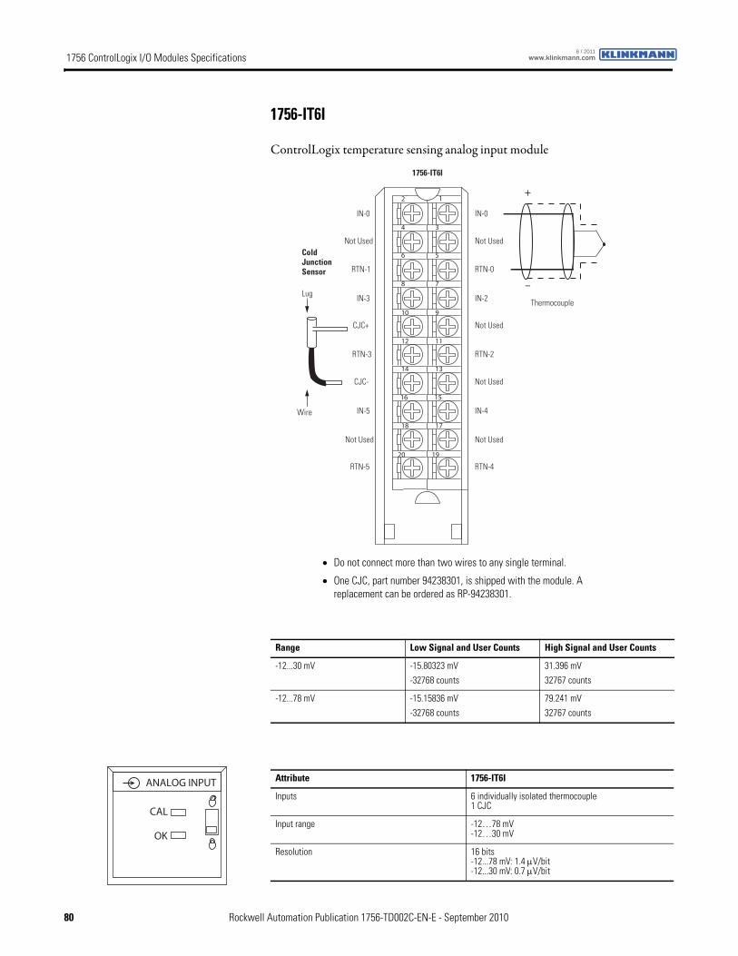
1756 ControlLogix I/O Modules Specifications www.klinkmann.com6 / 2011
1756-IT6I
ControlLogix temperature sensing analog input module
12
34
56
78
910
1112
1314
1516
1718
1920
+
–
Cold Junction Sensor
Thermocouple
Wire
IN-0
Not Used
RTN-0
IN-2
Not Used
RTN-2
Not Used
IN-4
Not Used
RTN-4
1756-IT6I
IN-0
Not Used
RTN-1
IN-3
CJC+
RTN-3
CJC-
IN-5
Not Used
RTN-5
Lug
• Do not connect more than two wires to any single terminal.
• One CJC, part number 94238301, is shipped with the module. A replacement can be ordered as RP-94238301.
Range Low Signal and User Counts High Signal and User Counts
-12...30 mV -15.80323 mV
-32768 counts
31.396 mV
32767 counts
-12...78 mV -15.15836 mV
-32768 counts
79.241 mV
32767 counts
Attribute 1756-IT6I
Inputs 6 individually isolated thermocouple1 CJC
Input range -12…78 mV-12…30 mV
Resolution 16 bits-12...78 mV: 1.4 μV/bit-12...30 mV: 0.7 μV/bit
ANALOG INPUT
CAL
OK
80 Rockwell Automation Publication 1756-TD002C-EN-E - September 2010
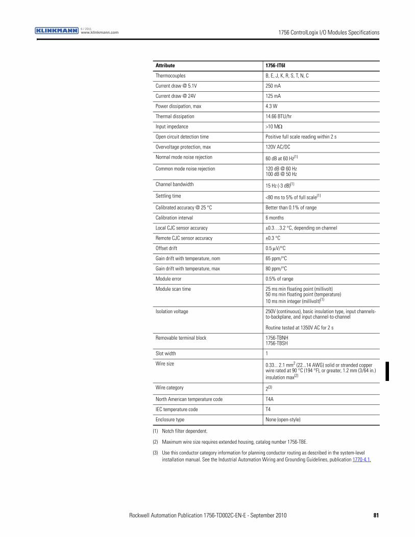
1756 ControlLogix I/O Modules Specificationswww.klinkmann.com6 / 2011
Thermocouples B, E, J, K, R, S, T, N, C
Current draw @ 5.1V 250 mA
Current draw @ 24V 125 mA
Power dissipation, max 4.3 W
Thermal dissipation 14.66 BTU/hr
Input impedance >10 MΩ
Open circuit detection time Positive full scale reading within 2 s
Overvoltage protection, max 120V AC/DC
Normal mode noise rejection 60 dB at 60 Hz(1)
Common mode noise rejection 120 dB @ 60 Hz100 dB @ 50 Hz
Channel bandwidth 15 Hz (-3 dB)(1)
Settling time <80 ms to 5% of full scale(1)
Calibrated accuracy @ 25 °C Better than 0.1% of range
Calibration interval 6 months
Local CJC sensor accuracy ±0.3…3.2 °C, depending on channel
Remote CJC sensor accuracy ±0.3 °C
Offset drift 0.5 μV/°C
Gain drift with temperature, nom 65 ppm/°C
Gain drift with temperature, max 80 ppm/°C
Module error 0.5% of range
Module scan time 25 ms min floating point (millivolt)50 ms min floating point (temperature)10 ms min integer (millivolt)(1)
Isolation voltage 250V (continuous), basic insulation type, input channels-to-backplane, and input channel-to-channel
Routine tested at 1350V AC for 2 s
Removable terminal block 1756-TBNH1756-TBSH
Slot width 1
Wire size 0.33... 2.1 mm2 (22...14 AWG) solid or stranded copper wire rated at 90 °C (194 °F), or greater, 1.2 mm (3/64 in.) insulation max(2)
Wire category 2(3)
North American temperature code T4A
IEC temperature code T4
Enclosure type None (open-style)
(1) Notch filter dependent.
(2) Maximum wire size requires extended housing, catalog number 1756-TBE.
(3) Use this conductor category information for planning conductor routing as described in the system-level installation manual. See the Industrial Automation Wiring and Grounding Guidelines, publication 1770-4.1.
Attribute 1756-IT6I
Rockwell Automation Publication 1756-TD002C-EN-E - September 2010 81
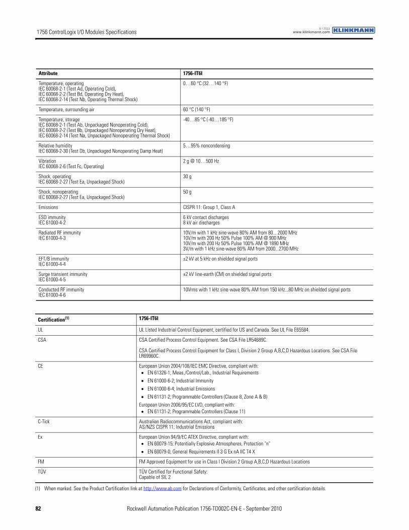
1756 ControlLogix I/O Modules Specifications www.klinkmann.com6 / 2011
Attribute 1756-IT6I
Temperature, operatingIEC 60068-2-1 (Test Ad, Operating Cold),IEC 60068-2-2 (Test Bd, Operating Dry Heat),IEC 60068-2-14 (Test Nb, Operating Thermal Shock)
0…60 °C (32…140 °F)
Temperature, surrounding air 60 °C (140 °F)
Temperature, storageIEC 60068-2-1 (Test Ab, Unpackaged Nonoperating Cold),IEC 60068-2-2 (Test Bb, Unpackaged Nonoperating Dry Heat),IEC 60068-2-14 (Test Na, Unpackaged Nonoperating Thermal Shock)
-40…85 °C (-40…185 °F)
Relative humidityIEC 60068-2-30 (Test Db, Unpackaged Nonoperating Damp Heat)
5…95% noncondensing
VibrationIEC 60068-2-6 (Test Fc, Operating)
2 g @ 10…500 Hz
Shock, operatingIEC 60068-2-27 (Test Ea, Unpackaged Shock)
30 g
Shock, nonoperatingIEC 60068-2-27 (Test Ea, Unpackaged Shock)
50 g
Emissions CISPR 11: Group 1, Class A
ESD immunityIEC 61000-4-2
6 kV contact discharges8 kV air discharges
Radiated RF immunityIEC 61000-4-3
10V/m with 1 kHz sine-wave 80% AM from 80... 2000 MHz10V/m with 200 Hz 50% Pulse 100% AM @ 900 MHz10V/m with 200 Hz 50% Pulse 100% AM @ 1890 MHz3V/m with 1 kHz sine-wave 80% AM from 2000...2700 MHz
EFT/B immunityIEC 61000-4-4
±2 kV at 5 kHz on shielded signal ports
Surge transient immunityIEC 61000-4-5
±2 kV line-earth (CM) on shielded signal ports
Conducted RF immunityIEC 61000-4-6
10Vrms with 1 kHz sine-wave 80% AM from 150 kHz...80 MHz on shielded signal ports
Certification(1) 1756-IT6I
UL UL Listed Industrial Control Equipment, certified for US and Canada. See UL File E65584.
CSA CSA Certified Process Control Equipment. See CSA File LR54689C.
CSA Certified Process Control Equipment for Class I, Division 2 Group A,B,C,D Hazardous Locations. See CSA File LR69960C.
CE European Union 2004/108/IEC EMC Directive, compliant with:• EN 61326-1; Meas./Control/Lab., Industrial Requirements
• EN 61000-6-2; Industrial Immunity
• EN 61000-6-4; Industrial Emissions
• EN 61131-2; Programmable Controllers (Clause 8, Zone A & B)
European Union 2006/95/EC LVD, compliant with:• EN 61131-2; Programmable Controllers (Clause 11)
C-Tick Australian Radiocommunications Act, compliant with:AS/NZS CISPR 11; Industrial Emissions
Ex European Union 94/9/EC ATEX Directive, compliant with:• EN 60079-15; Potentially Explosive Atmospheres, Protection "n"
• EN 60079-0; General Requirements II 3 G Ex nA IIC T4 X
FM FM Approved Equipment for use in Class I Division 2 Group A,B,C,D Hazardous Locations
TÜV TÜV Certified for Functional Safety:Capable of SIL 2
(1) When marked. See the Product Certification link at http://www.ab.com for Declarations of Conformity, Certificates, and other certification details.
82 Rockwell Automation Publication 1756-TD002C-EN-E - September 2010
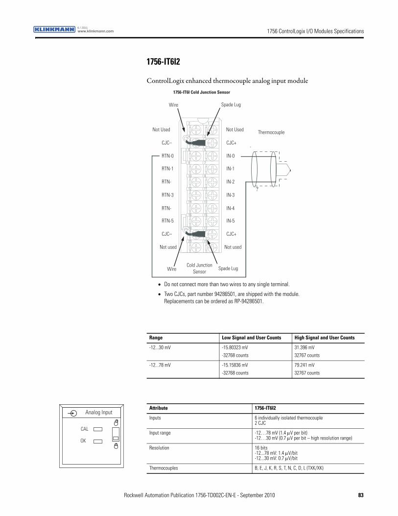
1756 ControlLogix I/O Modules Specificationswww.klinkmann.com6 / 2011
1756-IT6I2
ControlLogix enhanced thermocouple analog input module
?
Cold Junction Sensor
Thermocouple
Wire
Not Used
CJC–
RTN-0
RTN-1
RTN-
RTN-3
RTN-
RTN-5
CJC–
Not used
Spade Lug
Not Used
CJC+
IN-0
IN-1
IN-2
IN-3
IN-4
IN-5
CJC+
Not used
Wire Spade Lug
1756-IT6I Cold Junction Sensor
• Do not connect more than two wires to any single terminal.
• Two CJCs, part number 94286501, are shipped with the module. Replacements can be ordered as RP-94286501.
Range Low Signal and User Counts High Signal and User Counts
-12...30 mV -15.80323 mV
-32768 counts
31.396 mV
32767 counts
-12...78 mV -15.15836 mV
-32768 counts
79.241 mV
32767 counts
Attribute 1756-IT6I2
Inputs 6 individually isolated thermocouple2 CJC
Input range -12…78 mV (1.4 μV per bit)-12…30 mV (0.7 μV per bit – high resolution range)
Resolution 16 bits-12...78 mV: 1.4 μV/bit-12...30 mV: 0.7 μV/bit
Thermocouples B, E, J, K, R, S, T, N, C, D, L (TXK/XK)
Analog Input
CAL
OK
Rockwell Automation Publication 1756-TD002C-EN-E - September 2010 83
1756 ControlLogix I/O Modules Specifications www.klinkmann.com6 / 2011
Current draw @ 5.1V 200 mA
Current draw @ 24V 150 mA
Power dissipation, max 4.6 W
Thermal dissipation 15.7 BTU/hr
Open circuit detection time Positive full scale reading within 2 s
Overvoltage protection, max 120V AC/DC
Normal mode noise rejection 60 dB at 60 Hz(1)
Common mode noise rejection 160 dB min, tested @ 600V AC/60 Hz applied with 100 Ω differential resistance
Channel bandwidth 15 Hz(1)
Settling time <80 ms to 5% of full scale(1)
Calibrated accuracy @ 25 °C Better than 0.1% of range
Calibration interval 12 months
Local CJC sensor accuracy ±0.3 °C
Remote CJC sensor accuracy ±0.3 °C
Offset drift 0.5 μV/°C
Gain drift with temperature, nom 15 ppm/°C1.4 μV/°C for -12…78 mV0.6 μV/°C for -12…30 mV
Gain drift with temperature, max 25 ppm/°C2.3 μV/°C for -12…78 mV1.1 μV/°C for -12…30 mV
Module error 0.15% of range
Module scan time 25 ms min floating point (millivolt)50 ms min floating point (temperature)10 ms min integer (millivolt)(1)
Isolation voltage 250V (continuous), basic insulation type, input channels-to-backplane, and input channel-to-channel
Routine tested at 1350V AC for 2 s
Removable terminal block 1756-TBNH1756-TBSH
Slot width 1
Wire size 0.33... 2.1 mm2 (22...14 AWG) solid or stranded copper wire rated at 90 °C (194 °F), or greater, 1.2 mm (3/64 in.) insulation max(2)
Wire category 2(3)
North American temperature code T4A
IEC temperature code T4
Enclosure type None (open-style)
(1) Notch filter dependent.
(2) Maximum wire size requires extended housing, catalog number 1756-TBE.
(3) Use this conductor category information for planning conductor routing as described in the system-level installation manual. See the Industrial Automation Wiring and Grounding Guidelines, publication 1770-4.1.
Attribute 1756-IT6I2
84 Rockwell Automation Publication 1756-TD002C-EN-E - September 2010
1756 ControlLogix I/O Modules Specificationswww.klinkmann.com6 / 2011
Attribute 1756-IT6I2
Temperature, operatingIEC 60068-2-1 (Test Ad, Operating Cold),IEC 60068-2-2 (Test Bd, Operating Dry Heat),IEC 60068-2-14 (Test Nb, Operating Thermal Shock)
0…60 °C (32…140 °F)
Temperature, surrounding air 60 °C (140 °F)
Temperature, storageIEC 60068-2-1 (Test Ab, Unpackaged Nonoperating Cold),IEC 60068-2-2 (Test Bb, Unpackaged Nonoperating Dry Heat),IEC 60068-2-14 (Test Na, Unpackaged Nonoperating Thermal Shock)
-40…85 °C (-40…185 °F)
Relative humidityIEC 60068-2-30 (Test Db, Unpackaged Nonoperating Damp Heat)
5…95% noncondensing
VibrationIEC 60068-2-6 (Test Fc, Operating)
2 g @ 10…500 Hz
Shock, operatingIEC 60068-2-27 (Test Ea, Unpackaged Shock)
30 g
Shock, nonoperatingIEC 60068-2-27 (Test Ea, Unpackaged Shock)
50 g
Emissions CISPR 11: Group 1, Class A
ESD immunityIEC 61000-4-2
6 kV contact discharges8 kV air discharges
Radiated RF immunityIEC 61000-4-3
10V/m with 1 kHz sine-wave 80% AM from 80... 2000 MHz10V/m with 200 Hz 50% Pulse 100% AM @ 900 MHz10V/m with 200 Hz 50% Pulse 100% AM @ 1890 MHz3V/m with 1 kHz sine-wave 80% AM from 2000...2700 MHz
EFT/B immunityIEC 61000-4-4
±2 kV at 5 kHz on shielded signal ports
Surge transient immunityIEC 61000-4-5
±2 kV line-earth (CM) on shielded signal ports
Conducted RF immunityIEC 61000-4-6
10Vrms with 1 kHz sine-wave 80% AM from 150 kHz...80 MHz on shielded signal ports
Certification(1) 1756-IT6I2
UL UL Listed Industrial Control Equipment, certified for US and Canada. See UL File E65584.
CSA CSA Certified Process Control Equipment. See CSA File LR54689C.
CSA Certified Process Control Equipment for Class I, Division 2 Group A,B,C,D Hazardous Locations. See CSA File LR69960C.
CE European Union 2004/108/IEC EMC Directive, compliant with:• EN 61326-1; Meas./Control/Lab., Industrial Requirements
• EN 61000-6-2; Industrial Immunity
• EN 61000-6-4; Industrial Emissions
• EN 61131-2; Programmable Controllers (Clause 8, Zone A & B)
European Union 2006/95/EC LVD, compliant with:• EN 61131-2; Programmable Controllers (Clause 11)
C-Tick Australian Radiocommunications Act, compliant with:AS/NZS CISPR 11; Industrial Emissions
Ex European Union 94/9/EC ATEX Directive, compliant with:• EN 60079-15; Potentially Explosive Atmospheres, Protection "n"
• EN 60079-0; General Requirements II 3 G Ex nA IIC T4 X
FM FM Approved Equipment for use in Class I Division 2 Group A,B,C,D Hazardous Locations
TÜV TÜV Certified for Functional Safety:Capable of SIL 2
(1) When marked. See the Product Certification link at http://www.ab.com for Declarations of Conformity, Certificates, and other certification details.
Rockwell Automation Publication 1756-TD002C-EN-E - September 2010 85
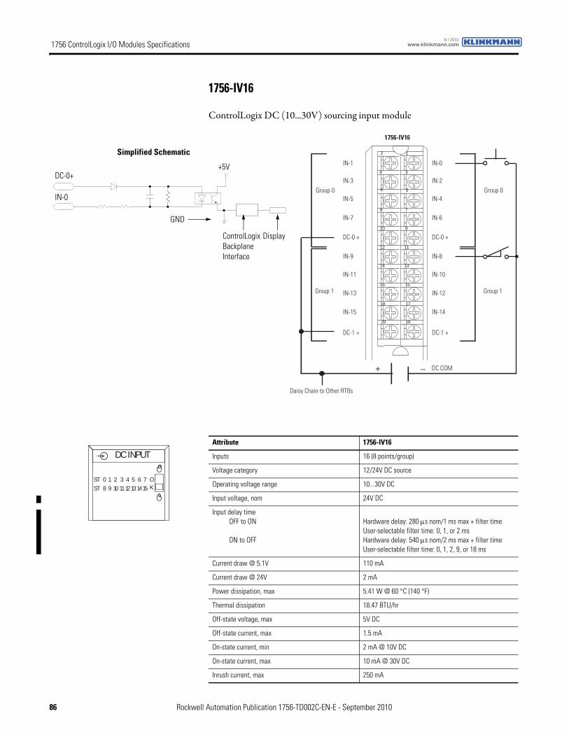
1756 ControlLogix I/O Modules Specifications www.klinkmann.com6 / 2011
1756-IV16
ControlLogix DC (10...30V) sourcing input module
1756-IV16
12
34
56
78
910
1112
1314
1516
1718
1920
–+
Daisy Chain to Other RTBs
Group 0Group 0
Group 1Group 1
DC COM
IN-0
IN-2
IN-4
IN-6
DC-0 +
IN-8
IN-10
IN-12
IN-14
DC-1 +
IN-1
IN-3
IN-5
IN-7
DC-0 +
IN-9
IN-11
IN-13
IN-15
DC-1 +
ControlLogix Backplane Interface
Simplified Schematic
Display
GND
IN-0
DC-0++5V
Attribute 1756-IV16
Inputs 16 (8 points/group)
Voltage category 12/24V DC source
Operating voltage range 10...30V DC
Input voltage, nom 24V DC
Input delay timeOFF to ON
ON to OFF
Hardware delay: 280 μs nom/1 ms max + filter timeUser-selectable filter time: 0, 1, or 2 msHardware delay: 540 μs nom/2 ms max + filter timeUser-selectable filter time: 0, 1, 2, 9, or 18 ms
Current draw @ 5.1V 110 mA
Current draw @ 24V 2 mA
Power dissipation, max 5.41 W @ 60 °C (140 °F)
Thermal dissipation 18.47 BTU/hr
Off-state voltage, max 5V DC
Off-state current, max 1.5 mA
On-state current, min 2 mA @ 10V DC
On-state current, max 10 mA @ 30V DC
Inrush current, max 250 mA
DC INPUT
ST 0 1 2 3 4 5 6 7ST 8 9 10 1112131415
OK
86 Rockwell Automation Publication 1756-TD002C-EN-E - September 2010
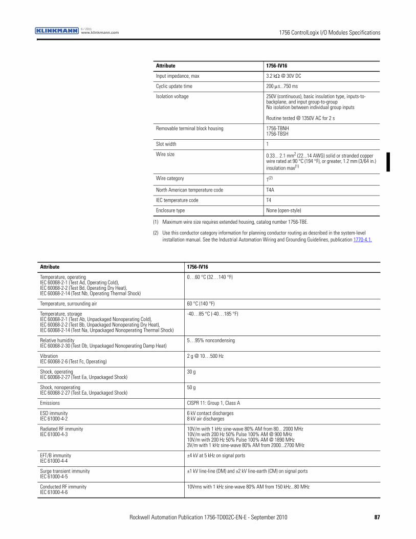
1756 ControlLogix I/O Modules Specificationswww.klinkmann.com6 / 2011
Input impedance, max 3.2 kΩ @ 30V DC
Cyclic update time 200 μs...750 ms
Isolation voltage 250V (continuous), basic insulation type, inputs-to-backplane, and input group-to-groupNo isolation between individual group inputs
Routine tested @ 1350V AC for 2 s
Removable terminal block housing 1756-TBNH1756-TBSH
Slot width 1
Wire size 0.33... 2.1 mm2 (22...14 AWG) solid or stranded copper wire rated at 90 °C (194 °F), or greater, 1.2 mm (3/64 in.) insulation max(1)
Wire category 1(2)
North American temperature code T4A
IEC temperature code T4
Enclosure type None (open-style)
(1) Maximum wire size requires extended housing, catalog number 1756-TBE.
(2) Use this conductor category information for planning conductor routing as described in the system-level installation manual. See the Industrial Automation Wiring and Grounding Guidelines, publication 1770-4.1.
Attribute 1756-IV16
Attribute 1756-IV16
Temperature, operatingIEC 60068-2-1 (Test Ad, Operating Cold),IEC 60068-2-2 (Test Bd, Operating Dry Heat),IEC 60068-2-14 (Test Nb, Operating Thermal Shock)
0…60 °C (32…140 °F)
Temperature, surrounding air 60 °C (140 °F)
Temperature, storageIEC 60068-2-1 (Test Ab, Unpackaged Nonoperating Cold),IEC 60068-2-2 (Test Bb, Unpackaged Nonoperating Dry Heat),IEC 60068-2-14 (Test Na, Unpackaged Nonoperating Thermal Shock)
-40…85 °C (-40…185 °F)
Relative humidityIEC 60068-2-30 (Test Db, Unpackaged Nonoperating Damp Heat)
5…95% noncondensing
VibrationIEC 60068-2-6 (Test Fc, Operating)
2 g @ 10…500 Hz
Shock, operatingIEC 60068-2-27 (Test Ea, Unpackaged Shock)
30 g
Shock, nonoperatingIEC 60068-2-27 (Test Ea, Unpackaged Shock)
50 g
Emissions CISPR 11: Group 1, Class A
ESD immunityIEC 61000-4-2
6 kV contact discharges8 kV air discharges
Radiated RF immunityIEC 61000-4-3
10V/m with 1 kHz sine-wave 80% AM from 80... 2000 MHz10V/m with 200 Hz 50% Pulse 100% AM @ 900 MHz10V/m with 200 Hz 50% Pulse 100% AM @ 1890 MHz3V/m with 1 kHz sine-wave 80% AM from 2000...2700 MHz
EFT/B immunityIEC 61000-4-4
±4 kV at 5 kHz on signal ports
Surge transient immunityIEC 61000-4-5
±1 kV line-line (DM) and ±2 kV line-earth (CM) on signal ports
Conducted RF immunityIEC 61000-4-6
10Vrms with 1 kHz sine-wave 80% AM from 150 kHz...80 MHz
Rockwell Automation Publication 1756-TD002C-EN-E - September 2010 87
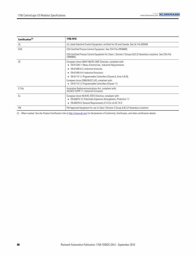
1756 ControlLogix I/O Modules Specifications www.klinkmann.com6 / 2011
Certification(1) 1756-IV16
UL UL Listed Industrial Control Equipment, certified for US and Canada. See UL File E65584.
CSA CSA Certified Process Control Equipment. See CSA File LR54689C.
CSA Certified Process Control Equipment for Class I, Division 2 Group A,B,C,D Hazardous Locations. See CSA File LR69960C.
CE European Union 2004/108/IEC EMC Directive, compliant with:• EN 61326-1; Meas./Control/Lab., Industrial Requirements
• EN 61000-6-2; Industrial Immunity
• EN 61000-6-4; Industrial Emissions
• EN 61131-2; Programmable Controllers (Clause 8, Zone A & B)
European Union 2006/95/EC LVD, compliant with:• EN 61131-2; Programmable Controllers (Clause 11)
C-Tick Australian Radiocommunications Act, compliant with:AS/NZS CISPR 11; Industrial Emissions
Ex European Union 94/9/EC ATEX Directive, compliant with:• EN 60079-15; Potentially Explosive Atmospheres, Protection "n"
• EN 60079-0; General Requirements II 3 G Ex nA IIC T4 X
FM FM Approved Equipment for use in Class I Division 2 Group A,B,C,D Hazardous Locations
(1) When marked. See the Product Certification link at http://www.ab.com for Declarations of Conformity, Certificates, and other certification details.
88 Rockwell Automation Publication 1756-TD002C-EN-E - September 2010
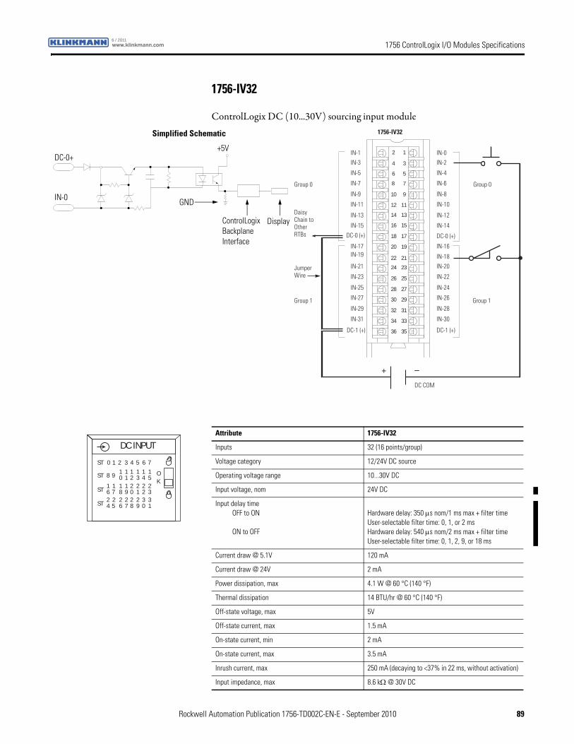
1756 ControlLogix I/O Modules Specificationswww.klinkmann.com6 / 2011
1756-IV32
ControlLogix DC (10...30V) sourcing input module
12
34
56
78
910
1112
1314
1516
1718
1920
2122
2324
2526
2728
2930
3132
3334
3536
+ –
Daisy Chain to Other RTBs
DC COM
0 puorG0 puorG
1 puorG1 puorG
1756-IV32
IN-1
IN-3
IN-5
IN-7
DC-0 (+)
IN-9
IN-11
IN-13
IN-15
DC-1 (+)
IN-17IN-19
IN-21
IN-23
IN-25
IN-27
IN-29
IN-31
IN-0
IN-2
IN-4
IN-6
DC-0 (+)
IN-8
IN-10
IN-12
IN-14
DC-1 (+)
IN-16
IN-18
IN-20
IN-22
IN-24
IN-26
IN-28
IN-30
Jumper Wire
ControlLogix Backplane Interface
Simplified Schematic
Display
IN-0 GND
DC-0++5V
Attribute 1756-IV32
Inputs 32 (16 points/group)
Voltage category 12/24V DC source
Operating voltage range 10...30V DC
Input voltage, nom 24V DC
Input delay timeOFF to ON
ON to OFF
Hardware delay: 350 μs nom/1 ms max + filter timeUser-selectable filter time: 0, 1, or 2 msHardware delay: 540 μs nom/2 ms max + filter timeUser-selectable filter time: 0, 1, 2, 9, or 18 ms
Current draw @ 5.1V 120 mA
Current draw @ 24V 2 mA
Power dissipation, max 4.1 W @ 60 °C (140 °F)
Thermal dissipation 14 BTU/hr @ 60 °C (140 °F)
Off-state voltage, max 5V
Off-state current, max 1.5 mA
On-state current, min 2 mA
On-state current, max 3.5 mA
Inrush current, max 250 mA (decaying to <37% in 22 ms, without activation)
Input impedance, max 8.6 kΩ @ 30V DC
DC INPUT
OK
ST 0 1 2 3 4 5 6 7
ST 8 9 10 21 3 4 5
1 1 1 11
ST 6 718 09 1 2 3
1 2 2 221 1
ST 4 526 87 9 0 1
2 2 2 332 2
Rockwell Automation Publication 1756-TD002C-EN-E - September 2010 89
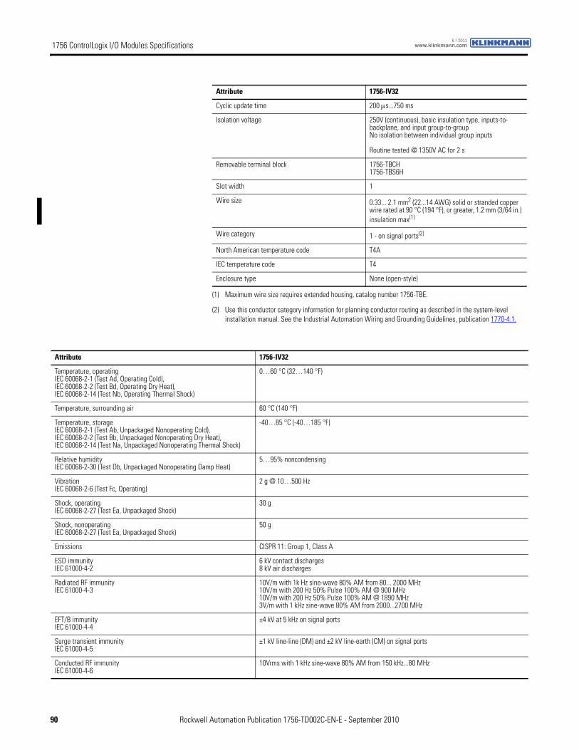
1756 ControlLogix I/O Modules Specifications www.klinkmann.com6 / 2011
Cyclic update time 200 μs...750 ms
Isolation voltage 250V (continuous), basic insulation type, inputs-to-backplane, and input group-to-groupNo isolation between individual group inputs
Routine tested @ 1350V AC for 2 s
Removable terminal block 1756-TBCH1756-TBS6H
Slot width 1
Wire size 0.33... 2.1 mm2 (22...14 AWG) solid or stranded copper wire rated at 90 °C (194 °F), or greater, 1.2 mm (3/64 in.) insulation max(1)
Wire category 1 - on signal ports(2)
North American temperature code T4A
IEC temperature code T4
Enclosure type None (open-style)
(1) Maximum wire size requires extended housing, catalog number 1756-TBE.
(2) Use this conductor category information for planning conductor routing as described in the system-level installation manual. See the Industrial Automation Wiring and Grounding Guidelines, publication 1770-4.1.
Attribute 1756-IV32
Attribute 1756-IV32
Temperature, operatingIEC 60068-2-1 (Test Ad, Operating Cold),IEC 60068-2-2 (Test Bd, Operating Dry Heat),IEC 60068-2-14 (Test Nb, Operating Thermal Shock)
0…60 °C (32…140 °F)
Temperature, surrounding air 60 °C (140 °F)
Temperature, storageIEC 60068-2-1 (Test Ab, Unpackaged Nonoperating Cold),IEC 60068-2-2 (Test Bb, Unpackaged Nonoperating Dry Heat),IEC 60068-2-14 (Test Na, Unpackaged Nonoperating Thermal Shock)
-40…85 °C (-40…185 °F)
Relative humidityIEC 60068-2-30 (Test Db, Unpackaged Nonoperating Damp Heat)
5…95% noncondensing
VibrationIEC 60068-2-6 (Test Fc, Operating)
2 g @ 10…500 Hz
Shock, operatingIEC 60068-2-27 (Test Ea, Unpackaged Shock)
30 g
Shock, nonoperatingIEC 60068-2-27 (Test Ea, Unpackaged Shock)
50 g
Emissions CISPR 11: Group 1, Class A
ESD immunityIEC 61000-4-2
6 kV contact discharges8 kV air discharges
Radiated RF immunityIEC 61000-4-3
10V/m with 1k Hz sine-wave 80% AM from 80... 2000 MHz10V/m with 200 Hz 50% Pulse 100% AM @ 900 MHz10V/m with 200 Hz 50% Pulse 100% AM @ 1890 MHz3V/m with 1 kHz sine-wave 80% AM from 2000...2700 MHz
EFT/B immunityIEC 61000-4-4
±4 kV at 5 kHz on signal ports
Surge transient immunityIEC 61000-4-5
±1 kV line-line (DM) and ±2 kV line-earth (CM) on signal ports
Conducted RF immunityIEC 61000-4-6
10Vrms with 1 kHz sine-wave 80% AM from 150 kHz...80 MHz
90 Rockwell Automation Publication 1756-TD002C-EN-E - September 2010

1756 ControlLogix I/O Modules Specificationswww.klinkmann.com6 / 2011
Certification(1) 1756-IV32
UL UL Listed Industrial Control Equipment, certified for US and Canada. See UL File E65584.
CSA CSA Certified Process Control Equipment. See CSA File LR54689C.
CSA Certified Process Control Equipment for Class I, Division 2 Group A,B,C,D Hazardous Locations. See CSA File LR69960C.
CE European Union 2004/108/IEC EMC Directive, compliant with:• EN 61326-1; Meas./Control/Lab., Industrial Requirements
• EN 61000-6-2; Industrial Immunity
• EN 61000-6-4; Industrial Emissions
• EN 61131-2; Programmable Controllers (Clause 8, Zone A & B)
European Union 2006/95/EC LVD, compliant with:• EN 61131-2; Programmable Controllers (Clause 11)
C-Tick Australian Radiocommunications Act, compliant with:AS/NZS CISPR 11; Industrial Emissions
Ex European Union 94/9/EC ATEX Directive, compliant with:• EN 60079-15; Potentially Explosive Atmospheres, Protection "n"
• EN 60079-0; General Requirements II 3 G Ex nA IIC T4 X
FM FM Approved Equipment for use in Class I Division 2 Group A,B,C,D Hazardous Locations
(1) When marked. See the Product Certification link at http://www.ab.com for Declarations of Conformity, Certificates, and other certification details.
Rockwell Automation Publication 1756-TD002C-EN-E - September 2010 91
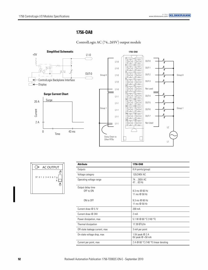
1756 ControlLogix I/O Modules Specifications www.klinkmann.com6 / 2011
1756-OA8
ControlLogix AC (74...265V) output module
12
34
56
78
910
1112
1314
1516
1718
1920
Daisy Chain to Other RTBs
Group 0Group 0
Group 1Group 1
L2
1756-OA8
L1-0
L1-0
L1-0
L1-0
L1-1
L1-1
L1-1
L1-1
L1-0
L1-1
OUT-0
OUT-1
OUT-2
OUT-3
OUT-4
OUT-5
OUT-6
OUT-7
Not used
Not Used
L1
ControlLogix Backplane Interface
Surge Current Chart
Curre
nt
Display
Simplified Schematic
OUT-0
Time
Surge
+5V L1-0
20 A
2 A
0 43 ms
Attribute 1756-OA8
Outputs 8 (4 points/group)
Voltage category 120/240V AC
Operating voltage range 74…265V AC47…63 Hz
Output delay timeOFF to ON
ON to OFF
9.3 ms @ 60 Hz11 ms @ 50 Hz
9.3 ms @ 60 Hz11 ms @ 50 Hz
Current draw @ 5.1V 200 mA
Current draw @ 24V 2 mA
Power dissipation, max 5.1 W @ 60 °C (140 °F)
Thermal dissipation 17.39 BTU/hr
Off-state leakage current, max 3 mA per point
On-state voltage drop, max 1.5V peak @ 2 A6V peak @ <50 mA
Current per point, max 2 A @ 60 °C (140 °F) linear derating
ST 0 1 2 3 4 5 6 7 OK
AC OUTPUT
92 Rockwell Automation Publication 1756-TD002C-EN-E - September 2010
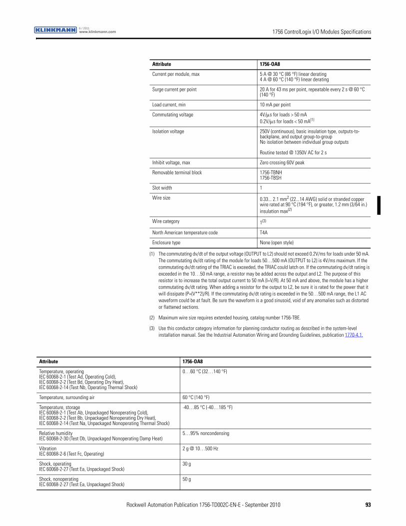
1756 ControlLogix I/O Modules Specificationswww.klinkmann.com6 / 2011
Current per module, max 5 A @ 30 °C (86 °F) linear derating4 A @ 60 °C (140 °F) linear derating
Surge current per point 20 A for 43 ms per point, repeatable every 2 s @ 60 °C (140 °F)
Load current, min 10 mA per point
Commutating voltage 4V/μs for loads > 50 mA0.2V/μs for loads < 50 mA(1)
Isolation voltage 250V (continuous), basic insulation type, outputs-to-backplane, and output group-to-groupNo isolation between individual group outputs
Routine tested @ 1350V AC for 2 s
Inhibit voltage, max Zero crossing 60V peak
Removable terminal block 1756-TBNH1756-TBSH
Slot width 1
Wire size 0.33... 2.1 mm2 (22...14 AWG) solid or stranded copper wire rated at 90 °C (194 °F), or greater, 1.2 mm (3/64 in.) insulation max(2)
Wire category 1(3)
North American temperature code T4A
Enclosure type None (open style)
(1) The commutating dv/dt of the output voltage (OUTPUT to L2) should not exceed 0.2V/ms for loads under 50 mA. The commutating dv/dt rating of the module for loads 50…500 mA (OUTPUT to L2) is 4V/ms maximum. If the commutating dv/dt rating of the TRIAC is exceeded, the TRIAC could latch on. If the commutating dv/dt rating is exceeded in the 10…50 mA range, a resistor may be added across the output and L2. The purpose of this resistor is to increase the total output current to 50 mA (I=V/R). At 50 mA and above, the module has a higher commutating dv/dt rating. When adding a resistor for the output to L2, be sure it is rated for the power that it will dissipate (P=(V**2)/R). If the commutating dv/dt rating is exceeded in the 50…500 mA range, the L1 AC waveform could be at fault. Be sure the waveform is a good sinusoid, void of any anomalies such as distorted or flattened sections.
(2) Maximum wire size requires extended housing, catalog number 1756-TBE.
(3) Use this conductor category information for planning conductor routing as described in the system-level installation manual. See the Industrial Automation Wiring and Grounding Guidelines, publication 1770-4.1.
Attribute 1756-OA8
Attribute 1756-OA8
Temperature, operatingIEC 60068-2-1 (Test Ad, Operating Cold),IEC 60068-2-2 (Test Bd, Operating Dry Heat),IEC 60068-2-14 (Test Nb, Operating Thermal Shock)
0…60 °C (32…140 °F)
Temperature, surrounding air 60 °C (140 °F)
Temperature, storageIEC 60068-2-1 (Test Ab, Unpackaged Nonoperating Cold),IEC 60068-2-2 (Test Bb, Unpackaged Nonoperating Dry Heat),IEC 60068-2-14 (Test Na, Unpackaged Nonoperating Thermal Shock)
-40…85 °C (-40…185 °F)
Relative humidityIEC 60068-2-30 (Test Db, Unpackaged Nonoperating Damp Heat)
5…95% noncondensing
VibrationIEC 60068-2-6 (Test Fc, Operating)
2 g @ 10…500 Hz
Shock, operatingIEC 60068-2-27 (Test Ea, Unpackaged Shock)
30 g
Shock, nonoperatingIEC 60068-2-27 (Test Ea, Unpackaged Shock)
50 g
Rockwell Automation Publication 1756-TD002C-EN-E - September 2010 93

1756 ControlLogix I/O Modules Specifications www.klinkmann.com6 / 2011
Emissions CISPR 11: Group 1, Class A
ESD immunityIEC 61000-4-2
6 kV contact discharges8k V air discharges
Radiated RF immunityIEC 61000-4-3
10V/m with 1 kHz sine-wave 80% AM from 80... 2000 MHz10V/m with 200 Hz 50% Pulse 100% AM @ 900 MHz10V/m with 200 Hz 50% Pulse 100% AM @ 1890 MHz3V/m with 1 kHz sine-wave 80% AM from 2000...2700 MHz
EFT/B immunityIEC 61000-4-4
±4 kV at 5 kHz on signal ports
Surge transient immunityIEC 61000-4-5
±1 kV line-line (DM) and ±2 kV line-earth (CM) on signal ports
Conducted RF immunityIEC 61000-4-6
10Vrms with 1 kHz sine-wave 80% AM from 150 kHz...80 MHz
Attribute 1756-OA8
Certification(1) 1756-OA8
UL UL Listed Industrial Control Equipment, certified for US and Canada. See UL File E65584.
CSA CSA Certified Process Control Equipment. See CSA File LR54689C.
CSA Certified Process Control Equipment for Class I, Division 2 Group A,B,C,D Hazardous Locations. See CSA File LR69960C.
CE European Union 2004/108/IEC EMC Directive, compliant with:• EN 61326-1; Meas./Control/Lab., Industrial Requirements
• EN 61000-6-2; Industrial Immunity
• EN 61000-6-4; Industrial Emissions
• EN 61131-2; Programmable Controllers (Clause 8, Zone A & B)
European Union 2006/95/EC LVD, compliant with:• EN 61131-2; Programmable Controllers
C-Tick Australian Radiocommunications Act, compliant with:AS/NZS CISPR 11; Industrial Emissions
FM FM Approved Equipment for use in Class I Division 2 Group A,B,C,D Hazardous Locations
(1) When marked. See the Product Certification link at http://www.ab.com for Declarations of Conformity, Certificates, and other certification details.
94 Rockwell Automation Publication 1756-TD002C-EN-E - September 2010
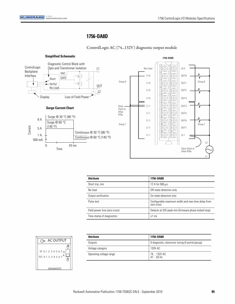
1756 ControlLogix I/O Modules Specificationswww.klinkmann.com6 / 2011
1756-OA8D
ControlLogix AC (74...132V) diagnostic output module
12
34
56
78
910
1112
1314
1516
1718
1920
Daisy Chain to Other RTBs
Daisy Chain to Other RTBs
Group 0Group 0
Group 1Group 1
L2
1756-OA8D
Not Used
L1-0
L1-0
L1-0
L1-1
L1-1
L1-1
L1-1
L1-0
L1-1
L2-0
OUT-0
OUT-1
OUT-2
OUT-4
OUT-5
OUT-6
OUT-7
OUT-3
L2-1
L1
ControlLogix Backplane Interface
Diagnostic Control Block with Opto and Transformer Isolation
Surge Current Chart
Continuous @ 30 °C (86 °F)Curre
nt
Display
Simplified Schematic
OUT
L1
Continuous @ 60 °C (140 °F)
Time
Surge @ 30 °C (86 °F)
Surge @ 60 °C(140 °F)
Loss of Field Power
Short
Verify/No Load
VAC
GATE
L2
500 mA
0 43 ms
1 A
5 A
8 A
Attribute 1756-OA8D
Short trip, min 12 A for 500 μs
No load Off-state detection only
Output verification On-state detection only
Pulse test Configurable maximum width and max time delay from zero cross
Field power loss (zero cross) Detects at 25V peak min (firmware phase locked loop)
Time stamp of diagnostics ±1 ms
Attribute 1756-OA8D
Outputs 8 diagnostic, electronic fusing (4 points/group)
Voltage category 120V AC
Operating voltage range 74…132V AC47…63 Hz
DIAGNOSTIC
ST 0 1 2 3 4 5 6 7 OK
AC OUTPUT
FLT 0 1 2 3 4 5 6 7
Rockwell Automation Publication 1756-TD002C-EN-E - September 2010 95
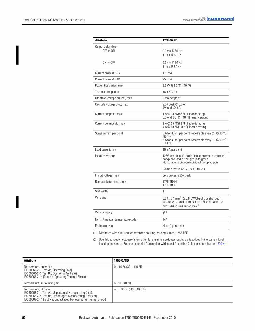
1756 ControlLogix I/O Modules Specifications www.klinkmann.com6 / 2011
Output delay timeOFF to ON
ON to OFF
9.3 ms @ 60 Hz11 ms @ 50 Hz
9.3 ms @ 60 Hz11 ms @ 50 Hz
Current draw @ 5.1V 175 mA
Current draw @ 24V 250 mA
Power dissipation, max 5.3 W @ 60 °C (140 °F)
Thermal dissipation 18.0 BTU/hr
Off-state leakage current, max 3 mA per point
On-state voltage drop, max 2.5V peak @ 0.5 A3V peak @ 1 A
Current per point, max 1 A @ 30 °C (86 °F) linear derating0.5 A @ 60 °C (140 °F) linear derating
Current per module, max 8 A @ 30 °C (86 °F) linear derating4 A @ 60 °C (140 °F) linear derating
Surge current per point 8 A for 43 ms per point, repeatable every 2 s @ 30 °C (86 °F)5 A for 43 ms per point, repeatable every 1 s @ 60 °C (140 °F)
Load current, min 10 mA per point
Isolation voltage 125V (continuous), basic insulation type, outputs-to-backplane, and output group-to-groupNo isolation between individual group outputs
Routine tested @ 1200V AC for 2 s
Inhibit voltage, max Zero crossing 25V peak
Removable terminal block 1756-TBNH1756-TBSH
Slot width 1
Wire size 0.33... 2.1 mm2 (22...14 AWG) solid or stranded copper wire rated at 90 °C (194 °F), or greater, 1.2 mm (3/64 in.) insulation max(1)
Wire category 1(2)
North American temperature code T4A
Enclosure type None (open style)
(1) Maximum wire size requires extended housing, catalog number 1756-TBE.
(2) Use this conductor category information for planning conductor routing as described in the system-level installation manual. See the Industrial Automation Wiring and Grounding Guidelines, publication 1770-4.1.
Attribute 1756-OA8D
Attribute 1756-OA8D
Temperature, operatingIEC 60068-2-1 (Test Ad, Operating Cold),IEC 60068-2-2 (Test Bd, Operating Dry Heat),IEC 60068-2-14 (Test Nb, Operating Thermal Shock)
0…60 °C (32…140 °F)
Temperature, surrounding air 60 °C (140 °F)
Temperature, storageIEC 60068-2-1 (Test Ab, Unpackaged Nonoperating Cold),IEC 60068-2-2 (Test Bb, Unpackaged Nonoperating Dry Heat),IEC 60068-2-14 (Test Na, Unpackaged Nonoperating Thermal Shock)
-40…85 °C (-40…185 °F)
96 Rockwell Automation Publication 1756-TD002C-EN-E - September 2010
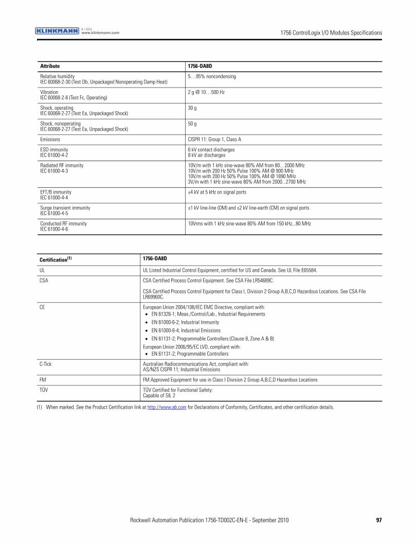
1756 ControlLogix I/O Modules Specificationswww.klinkmann.com6 / 2011
Relative humidityIEC 60068-2-30 (Test Db, Unpackaged Nonoperating Damp Heat)
5…95% noncondensing
VibrationIEC 60068-2-6 (Test Fc, Operating)
2 g @ 10…500 Hz
Shock, operatingIEC 60068-2-27 (Test Ea, Unpackaged Shock)
30 g
Shock, nonoperatingIEC 60068-2-27 (Test Ea, Unpackaged Shock)
50 g
Emissions CISPR 11: Group 1, Class A
ESD immunityIEC 61000-4-2
6 kV contact discharges8 kV air discharges
Radiated RF immunityIEC 61000-4-3
10V/m with 1 kHz sine-wave 80% AM from 80... 2000 MHz10V/m with 200 Hz 50% Pulse 100% AM @ 900 MHz10V/m with 200 Hz 50% Pulse 100% AM @ 1890 MHz3V/m with 1 kHz sine-wave 80% AM from 2000...2700 MHz
EFT/B immunityIEC 61000-4-4
±4 kV at 5 kHz on signal ports
Surge transient immunityIEC 61000-4-5
±1 kV line-line (DM) and ±2 kV line-earth (CM) on signal ports
Conducted RF immunityIEC 61000-4-6
10Vrms with 1 kHz sine-wave 80% AM from 150 kHz...80 MHz
Attribute 1756-OA8D
Certification(1) 1756-OA8D
UL UL Listed Industrial Control Equipment, certified for US and Canada. See UL File E65584.
CSA CSA Certified Process Control Equipment. See CSA File LR54689C.
CSA Certified Process Control Equipment for Class I, Division 2 Group A,B,C,D Hazardous Locations. See CSA File LR69960C.
CE European Union 2004/108/IEC EMC Directive, compliant with:• EN 61326-1; Meas./Control/Lab., Industrial Requirements
• EN 61000-6-2; Industrial Immunity
• EN 61000-6-4; Industrial Emissions
• EN 61131-2; Programmable Controllers (Clause 8, Zone A & B)
European Union 2006/95/EC LVD, compliant with:• EN 61131-2; Programmable Controllers
C-Tick Australian Radiocommunications Act, compliant with:AS/NZS CISPR 11; Industrial Emissions
FM FM Approved Equipment for use in Class I Division 2 Group A,B,C,D Hazardous Locations
TÜV TÜV Certified for Functional Safety:Capable of SIL 2
(1) When marked. See the Product Certification link at http://www.ab.com for Declarations of Conformity, Certificates, and other certification details.
Rockwell Automation Publication 1756-TD002C-EN-E - September 2010 97
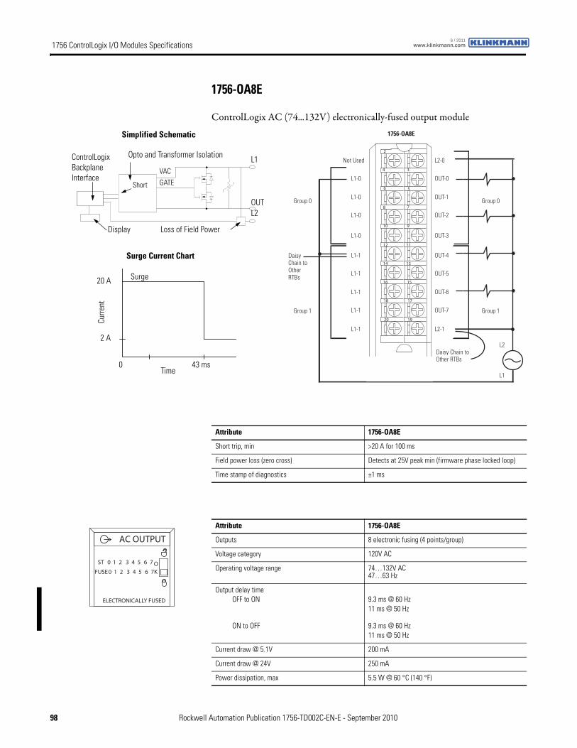
1756 ControlLogix I/O Modules Specifications www.klinkmann.com6 / 2011
1756-OA8E
ControlLogix AC (74...132V) electronically-fused output module
12
34
56
78
910
1112
1314
1516
1718
1920
Daisy Chain to Other RTBs
Group 0Group 0
Group 1Group 1
L2
1756-OA8E
Not Used
L1-0
L1-0
L1-0
L1-1
L1-1
L1-1
L1-1
L1-0
L1-1
L2-0
OUT-0
OUT-1
OUT-2
OUT-4
OUT-5
OUT-6
OUT-7
OUT-3
L2-1
Daisy Chain to Other RTBs
L1
ControlLogix Backplane Interface
Opto and Transformer Isolation
Surge Current Chart
Display
Simplified Schematic
OUT
L1
Time
Surge
Loss of Field Power
Short
VAC
GATE
0 43 ms
Curre
nt
20 A
2 A
L2
Attribute 1756-OA8E
Short trip, min >20 A for 100 ms
Field power loss (zero cross) Detects at 25V peak min (firmware phase locked loop)
Time stamp of diagnostics ±1 ms
Attribute 1756-OA8E
Outputs 8 electronic fusing (4 points/group)
Voltage category 120V AC
Operating voltage range 74…132V AC47…63 Hz
Output delay timeOFF to ON
ON to OFF
9.3 ms @ 60 Hz11 ms @ 50 Hz
9.3 ms @ 60 Hz11 ms @ 50 Hz
Current draw @ 5.1V 200 mA
Current draw @ 24V 250 mA
Power dissipation, max 5.5 W @ 60 °C (140 °F)
ST 0 1 2 3 4 5 6 7
FUSE 0 1 2 3 4 5 6 7OK
AC OUTPUT
ELECTRONICALLY FUSED
98 Rockwell Automation Publication 1756-TD002C-EN-E - September 2010
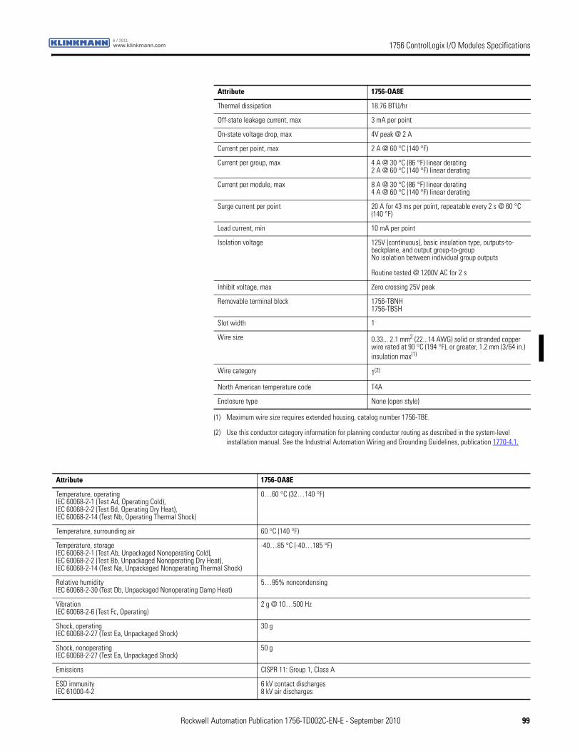
1756 ControlLogix I/O Modules Specificationswww.klinkmann.com6 / 2011
Thermal dissipation 18.76 BTU/hr
Off-state leakage current, max 3 mA per point
On-state voltage drop, max 4V peak @ 2 A
Current per point, max 2 A @ 60 °C (140 °F)
Current per group, max 4 A @ 30 °C (86 °F) linear derating2 A @ 60 °C (140 °F) linear derating
Current per module, max 8 A @ 30 °C (86 °F) linear derating4 A @ 60 °C (140 °F) linear derating
Surge current per point 20 A for 43 ms per point, repeatable every 2 s @ 60 °C (140 °F)
Load current, min 10 mA per point
Isolation voltage 125V (continuous), basic insulation type, outputs-to-backplane, and output group-to-groupNo isolation between individual group outputs
Routine tested @ 1200V AC for 2 s
Inhibit voltage, max Zero crossing 25V peak
Removable terminal block 1756-TBNH1756-TBSH
Slot width 1
Wire size 0.33... 2.1 mm2 (22...14 AWG) solid or stranded copper wire rated at 90 °C (194 °F), or greater, 1.2 mm (3/64 in.) insulation max(1)
Wire category 1(2)
North American temperature code T4A
Enclosure type None (open style)
(1) Maximum wire size requires extended housing, catalog number 1756-TBE.
(2) Use this conductor category information for planning conductor routing as described in the system-level installation manual. See the Industrial Automation Wiring and Grounding Guidelines, publication 1770-4.1.
Attribute 1756-OA8E
Attribute 1756-OA8E
Temperature, operatingIEC 60068-2-1 (Test Ad, Operating Cold),IEC 60068-2-2 (Test Bd, Operating Dry Heat),IEC 60068-2-14 (Test Nb, Operating Thermal Shock)
0…60 °C (32…140 °F)
Temperature, surrounding air 60 °C (140 °F)
Temperature, storageIEC 60068-2-1 (Test Ab, Unpackaged Nonoperating Cold),IEC 60068-2-2 (Test Bb, Unpackaged Nonoperating Dry Heat),IEC 60068-2-14 (Test Na, Unpackaged Nonoperating Thermal Shock)
-40…85 °C (-40…185 °F)
Relative humidityIEC 60068-2-30 (Test Db, Unpackaged Nonoperating Damp Heat)
5…95% noncondensing
VibrationIEC 60068-2-6 (Test Fc, Operating)
2 g @ 10…500 Hz
Shock, operatingIEC 60068-2-27 (Test Ea, Unpackaged Shock)
30 g
Shock, nonoperatingIEC 60068-2-27 (Test Ea, Unpackaged Shock)
50 g
Emissions CISPR 11: Group 1, Class A
ESD immunityIEC 61000-4-2
6 kV contact discharges8 kV air discharges
Rockwell Automation Publication 1756-TD002C-EN-E - September 2010 99

1756 ControlLogix I/O Modules Specifications www.klinkmann.com6 / 2011
Radiated RF immunityIEC 61000-4-3
10V/m with 1 kHz sine-wave 80% AM from 80... 2000 MHz10V/m with 200 Hz 50% Pulse 100% AM @ 900 MHz10V/m with 200 Hz 50% Pulse 100% AM @ 1890 MHz3V/m with 1 kHz sine-wave 80% AM from 2000...2700 MHz
EFT/B immunityIEC 61000-4-4
±4 kV at 5 kHz on signal ports
Surge transient immunityIEC 61000-4-5
±1k V line-line (DM) and ±2 kV line-earth (CM) on signal ports
Conducted RF immunityIEC 61000-4-6
10Vrms with 1 kHz sine-wave 80% AM from 150 kHz...80 MHz
Attribute 1756-OA8E
Certification(1) 1756-OA8E
UL UL Listed Industrial Control Equipment, certified for US and Canada. See UL File E65584.
CSA CSA Certified Process Control Equipment. See CSA File LR54689C.
CSA Certified Process Control Equipment for Class I, Division 2 Group A,B,C,D Hazardous Locations. See CSA File LR69960C.
CE European Union 2004/108/IEC EMC Directive, compliant with:• EN 61326-1; Meas./Control/Lab., Industrial Requirements
• EN 61000-6-2; Industrial Immunity
• EN 61000-6-4; Industrial Emissions
• EN 61131-2; Programmable Controllers (Clause 8, Zone A & B)
European Union 2006/95/EC LVD, compliant with:• EN 61131-2; Programmable Controllers
C-Tick Australian Radiocommunications Act, compliant with:AS/NZS CISPR 11; Industrial Emissions
FM FM Approved Equipment for use in Class I Division 2 Group A,B,C,D Hazardous Locations
(1) When marked. See the Product Certification link at http://www.ab.com for Declarations of Conformity, Certificates, and other certification details.
100 Rockwell Automation Publication 1756-TD002C-EN-E - September 2010
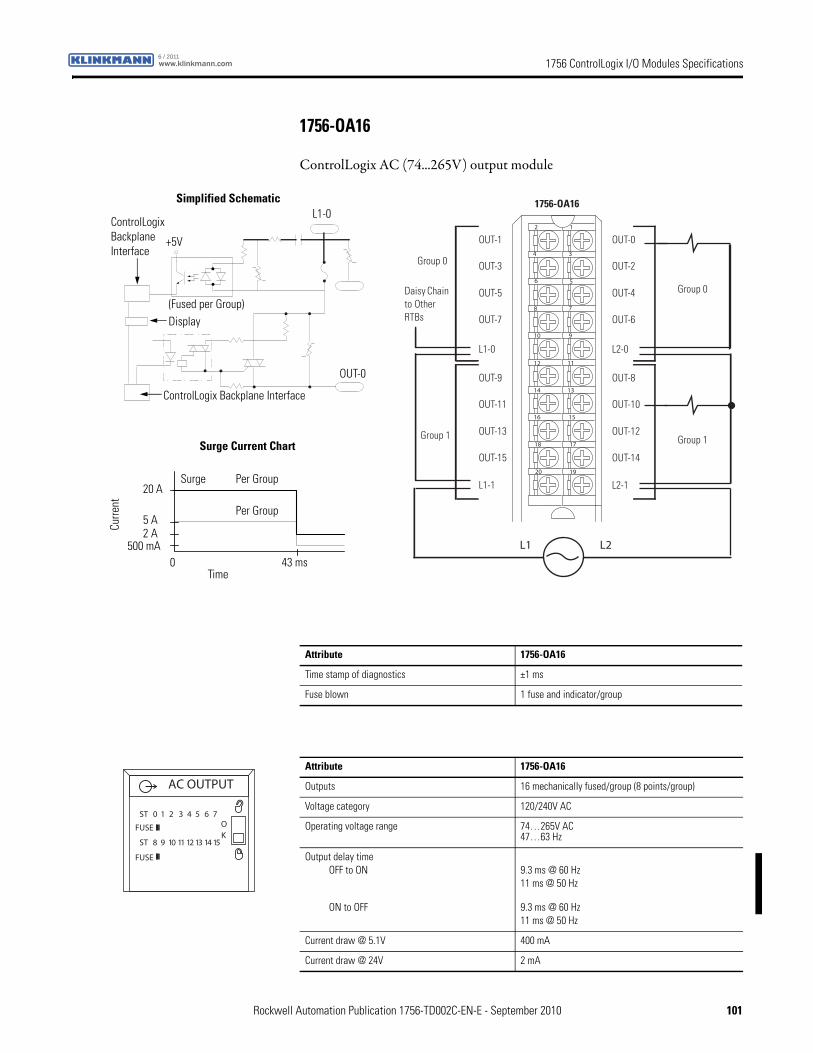
1756 ControlLogix I/O Modules Specificationswww.klinkmann.com6 / 2011
1756-OA16
ControlLogix AC (74...265V) output module
L1
12
34
56
78
910
1112
1314
1516
1718
1920
L1 L2
Daisy Chain to Other RTBs
1756-OA16
Group 0
Group 0
Group 1 Group 1
OUT-1
OUT-3
OUT-5
OUT-7
OUT-9
OUT-11
OUT-13
OUT-15
L1-0
L1-1
OUT-0
OUT-2
OUT-4
OUT-6
OUT-8
OUT-10
OUT-12
OUT-14
L2-0
L2-1
ControlLogix Backplane Interface
ControlLogix Backplane Interface
(Fused per Group)
Simplified Schematic
Per Group
Surge Current Chart
Per Group
Surge
Display
L1-0
OUT-0
Curre
nt
Time
500 mA0 43 ms
2 A5 A
20 A
+5V
Attribute 1756-OA16
Time stamp of diagnostics ±1 ms
Fuse blown 1 fuse and indicator/group
Attribute 1756-OA16
Outputs 16 mechanically fused/group (8 points/group)
Voltage category 120/240V AC
Operating voltage range 74…265V AC47…63 Hz
Output delay timeOFF to ON
ON to OFF
9.3 ms @ 60 Hz11 ms @ 50 Hz
9.3 ms @ 60 Hz11 ms @ 50 Hz
Current draw @ 5.1V 400 mA
Current draw @ 24V 2 mA
AC OUTPUT
ST 0 1 2 3 4 5 6 7
ST 8 9 10 11 12 13 14 15
OK
FUSE
FUSE
Rockwell Automation Publication 1756-TD002C-EN-E - September 2010 101
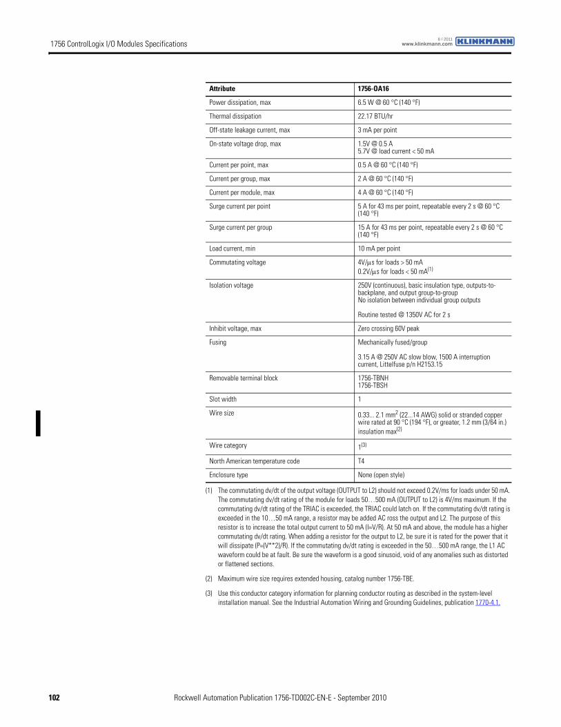
1756 ControlLogix I/O Modules Specifications www.klinkmann.com6 / 2011
Power dissipation, max 6.5 W @ 60 °C (140 °F)
Thermal dissipation 22.17 BTU/hr
Off-state leakage current, max 3 mA per point
On-state voltage drop, max 1.5V @ 0.5 A5.7V @ load current < 50 mA
Current per point, max 0.5 A @ 60 °C (140 °F)
Current per group, max 2 A @ 60 °C (140 °F)
Current per module, max 4 A @ 60 °C (140 °F)
Surge current per point 5 A for 43 ms per point, repeatable every 2 s @ 60 °C (140 °F)
Surge current per group 15 A for 43 ms per point, repeatable every 2 s @ 60 °C (140 °F)
Load current, min 10 mA per point
Commutating voltage 4V/μs for loads > 50 mA0.2V/μs for loads < 50 mA(1)
Isolation voltage 250V (continuous), basic insulation type, outputs-to-backplane, and output group-to-groupNo isolation between individual group outputs
Routine tested @ 1350V AC for 2 s
Inhibit voltage, max Zero crossing 60V peak
Fusing Mechanically fused/group
3.15 A @ 250V AC slow blow, 1500 A interruption current, Littelfuse p/n H2153.15
Removable terminal block 1756-TBNH1756-TBSH
Slot width 1
Wire size 0.33... 2.1 mm2 (22...14 AWG) solid or stranded copper wire rated at 90 °C (194 °F), or greater, 1.2 mm (3/64 in.) insulation max(2)
Wire category 1(3)
North American temperature code T4
Enclosure type None (open style)
(1) The commutating dv/dt of the output voltage (OUTPUT to L2) should not exceed 0.2V/ms for loads under 50 mA. The commutating dv/dt rating of the module for loads 50…500 mA (OUTPUT to L2) is 4V/ms maximum. If the commutating dv/dt rating of the TRIAC is exceeded, the TRIAC could latch on. If the commutating dv/dt rating is exceeded in the 10…50 mA range, a resistor may be added AC ross the output and L2. The purpose of this resistor is to increase the total output current to 50 mA (I=V/R). At 50 mA and above, the module has a higher commutating dv/dt rating. When adding a resistor for the output to L2, be sure it is rated for the power that it will dissipate (P=(V**2)/R). If the commutating dv/dt rating is exceeded in the 50…500 mA range, the L1 AC waveform could be at fault. Be sure the waveform is a good sinusoid, void of any anomalies such as distorted or flattened sections.
(2) Maximum wire size requires extended housing, catalog number 1756-TBE.
(3) Use this conductor category information for planning conductor routing as described in the system-level installation manual. See the Industrial Automation Wiring and Grounding Guidelines, publication 1770-4.1.
Attribute 1756-OA16
102 Rockwell Automation Publication 1756-TD002C-EN-E - September 2010
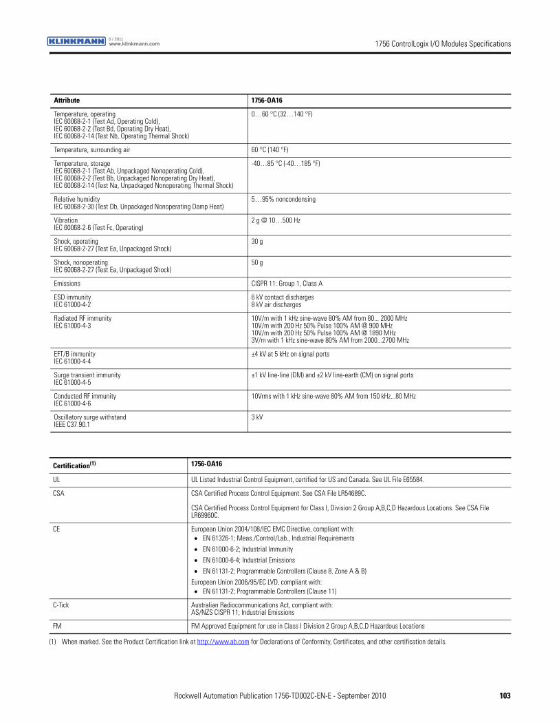
1756 ControlLogix I/O Modules Specificationswww.klinkmann.com6 / 2011
Attribute 1756-OA16
Temperature, operatingIEC 60068-2-1 (Test Ad, Operating Cold),IEC 60068-2-2 (Test Bd, Operating Dry Heat),IEC 60068-2-14 (Test Nb, Operating Thermal Shock)
0…60 °C (32…140 °F)
Temperature, surrounding air 60 °C (140 °F)
Temperature, storageIEC 60068-2-1 (Test Ab, Unpackaged Nonoperating Cold),IEC 60068-2-2 (Test Bb, Unpackaged Nonoperating Dry Heat),IEC 60068-2-14 (Test Na, Unpackaged Nonoperating Thermal Shock)
-40…85 °C (-40…185 °F)
Relative humidityIEC 60068-2-30 (Test Db, Unpackaged Nonoperating Damp Heat)
5…95% noncondensing
VibrationIEC 60068-2-6 (Test Fc, Operating)
2 g @ 10…500 Hz
Shock, operatingIEC 60068-2-27 (Test Ea, Unpackaged Shock)
30 g
Shock, nonoperatingIEC 60068-2-27 (Test Ea, Unpackaged Shock)
50 g
Emissions CISPR 11: Group 1, Class A
ESD immunityIEC 61000-4-2
6 kV contact discharges8 kV air discharges
Radiated RF immunityIEC 61000-4-3
10V/m with 1 kHz sine-wave 80% AM from 80... 2000 MHz10V/m with 200 Hz 50% Pulse 100% AM @ 900 MHz10V/m with 200 Hz 50% Pulse 100% AM @ 1890 MHz3V/m with 1 kHz sine-wave 80% AM from 2000...2700 MHz
EFT/B immunityIEC 61000-4-4
±4 kV at 5 kHz on signal ports
Surge transient immunityIEC 61000-4-5
±1 kV line-line (DM) and ±2 kV line-earth (CM) on signal ports
Conducted RF immunityIEC 61000-4-6
10Vrms with 1 kHz sine-wave 80% AM from 150 kHz...80 MHz
Oscillatory surge withstandIEEE C37.90.1
3 kV
Certification(1) 1756-OA16
UL UL Listed Industrial Control Equipment, certified for US and Canada. See UL File E65584.
CSA CSA Certified Process Control Equipment. See CSA File LR54689C.
CSA Certified Process Control Equipment for Class I, Division 2 Group A,B,C,D Hazardous Locations. See CSA File LR69960C.
CE European Union 2004/108/IEC EMC Directive, compliant with:• EN 61326-1; Meas./Control/Lab., Industrial Requirements
• EN 61000-6-2; Industrial Immunity
• EN 61000-6-4; Industrial Emissions
• EN 61131-2; Programmable Controllers (Clause 8, Zone A & B)
European Union 2006/95/EC LVD, compliant with:• EN 61131-2; Programmable Controllers (Clause 11)
C-Tick Australian Radiocommunications Act, compliant with:AS/NZS CISPR 11; Industrial Emissions
FM FM Approved Equipment for use in Class I Division 2 Group A,B,C,D Hazardous Locations
(1) When marked. See the Product Certification link at http://www.ab.com for Declarations of Conformity, Certificates, and other certification details.
Rockwell Automation Publication 1756-TD002C-EN-E - September 2010 103
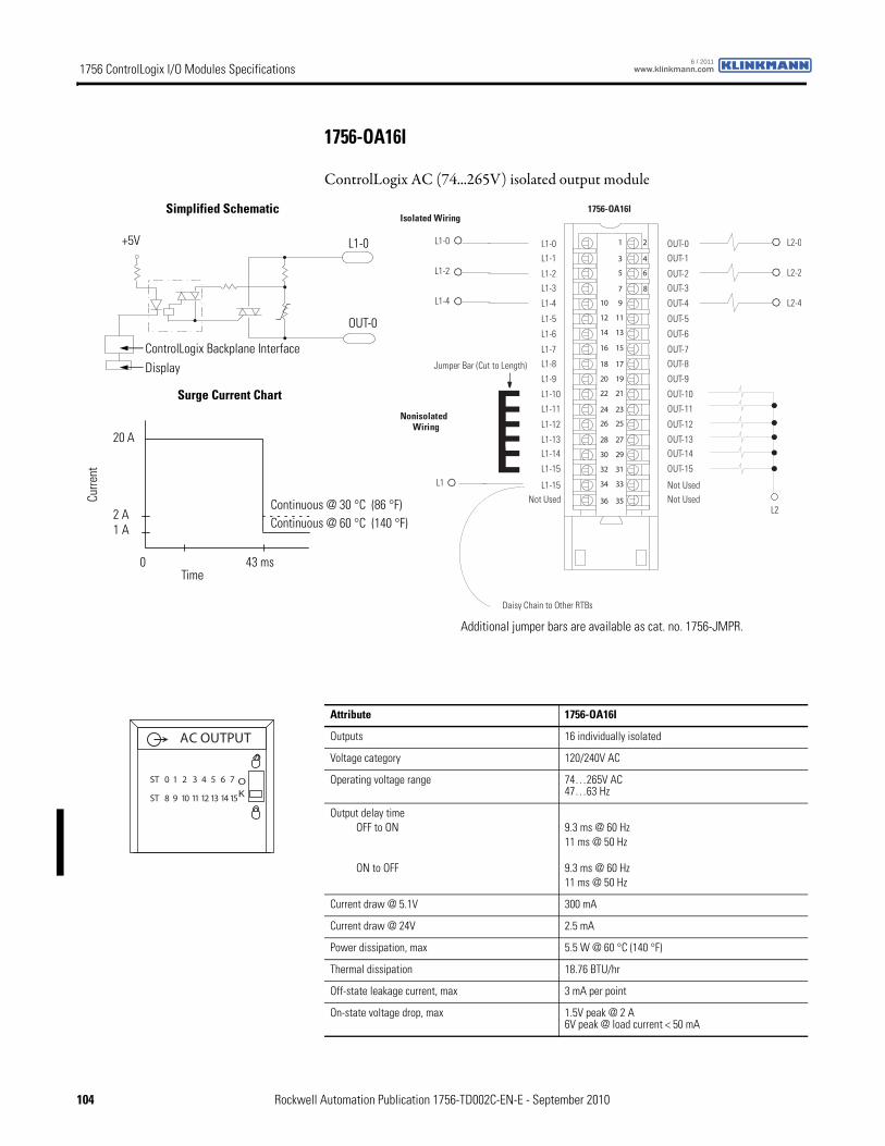
1756 ControlLogix I/O Modules Specifications www.klinkmann.com6 / 2011
1756-OA16I
ControlLogix AC (74...265V) isolated output module
1 2
3 4
5 6
7 8
01 9
21 11
41 31
61 51
81 71
02 91
22 12
42 32
62 52
82 72
03 92
23 13
43 33
63 53
Nonisolated Wiring
Isolated Wiring
Daisy Chain to Other RTBs
L1-0
1756-OA16I
L1-0
L1-1
L1-2
L1-3
L1-8
L1-4
L1-5
L1-6
L1-7
Not Used
L1-9
L1-10
L1-11
L1-12
L1-13L1-14
L1-15
L1-15
OUT-0
OUT-1
OUT-2
OUT-3
OUT-8
OUT-4
OUT-5
OUT-6
OUT-7
Not Used
OUT-9
OUT-10
OUT-11
OUT-12
OUT-13OUT-14
OUT-15
Not Used
L1-2
L1-4
L1
L2
L2-0
L2-2
L2-4
Jumper Bar (Cut to Length)
ControlLogix Backplane Interface
Surge Current Chart
Continuous @ 30 °C (86 °F)
Display
Simplified Schematic
OUT-0
L1-0
Continuous @ 60 °C (140 °F)
Curre
nt
Time
1 A
0 43 ms
2 A
20 A
+5V
Additional jumper bars are available as cat. no. 1756-JMPR.
Attribute 1756-OA16I
Outputs 16 individually isolated
Voltage category 120/240V AC
Operating voltage range 74…265V AC47…63 Hz
Output delay timeOFF to ON
ON to OFF
9.3 ms @ 60 Hz11 ms @ 50 Hz
9.3 ms @ 60 Hz11 ms @ 50 Hz
Current draw @ 5.1V 300 mA
Current draw @ 24V 2.5 mA
Power dissipation, max 5.5 W @ 60 °C (140 °F)
Thermal dissipation 18.76 BTU/hr
Off-state leakage current, max 3 mA per point
On-state voltage drop, max 1.5V peak @ 2 A6V peak @ load current < 50 mA
ST 0 1 2 3 4 5 6 7
ST 8 9 10 11 12 13 14 15
OK
AC OUTPUT
104 Rockwell Automation Publication 1756-TD002C-EN-E - September 2010
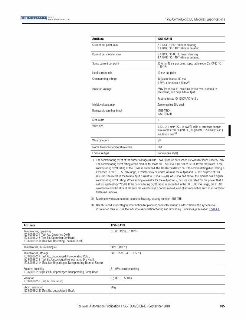
1756 ControlLogix I/O Modules Specificationswww.klinkmann.com6 / 2011
Current per point, max 2 A @ 30 ° (86 °F) linear derating1 A @ 60 °C (140 °F) linear derating
Current per module, max 5 A @ 30 °C (86 °F) linear derating4 A @ 60 °C (140 °F) linear derating
Surge current per point 20 A for 43 ms per point, repeatable every 2 s @ 60 °C (140 °F)
Load current, min 10 mA per point
Commutating voltage 4V/μs for loads > 50 mA0.2V/μs for loads < 50 mA(1)
Isolation voltage 250V (continuous), basic insulation type, outputs-to-backplane, and output-to-output
Routine tested @ 1350V AC for 2 s
Inhibit voltage, max Zero crossing 60V peak
Removable terminal block 1756-TBCH1756-TBS6H
Slot width 1
Wire size 0.33... 2.1 mm2 (22...14 AWG) solid or stranded copper wire rated at 90 °C (194 °F), or greater, 1.2 mm (3/64 in.) insulation max(2)
Wire category 1(3)
North American temperature code T4A
Enclosure type None (open style)
(1) The commutating dv/dt of the output voltage (OUTPUT to L2) should not exceed 0.2V/ms for loads under 50 mA. The commutating dv/dt rating of the module for loads 50…500 mA (OUTPUT to L2) is 4V/ms maximum. If the commutating dv/dt rating of the TRIAC is exceeded, the TRIAC could latch on. If the commutating dv/dt rating is exceeded in the 10…50 mA range, a resistor may be added AC ross the output and L2. The purpose of this resistor is to increase the total output current to 50 mA (I=V/R). At 50 mA and above, the module has a higher commutating dv/dt rating. When adding a resistor for the output to L2, be sure it is rated for the power that it will dissipate (P=(V**2)/R). If the commutating dv/dt rating is exceeded in the 50…500 mA range, the L1 AC waveform could be at fault. Be sure the waveform is a good sinusoid, void of any anomalies such as distorted or flattened sections.
(2) Maximum wire size requires extended housing, catalog number 1756-TBE.
(3) Use this conductor category information for planning conductor routing as described in the system-level installation manual. See the Industrial Automation Wiring and Grounding Guidelines, publication 1770-4.1.
Attribute 1756-OA16I
Attribute 1756-OA16I
Temperature, operatingIEC 60068-2-1 (Test Ad, Operating Cold),IEC 60068-2-2 (Test Bd, Operating Dry Heat),IEC 60068-2-14 (Test Nb, Operating Thermal Shock)
0…60 °C (32…140 °F)
Temperature, surrounding air 60 °C (140 °F)
Temperature, storageIEC 60068-2-1 (Test Ab, Unpackaged Nonoperating Cold),IEC 60068-2-2 (Test Bb, Unpackaged Nonoperating Dry Heat),IEC 60068-2-14 (Test Na, Unpackaged Nonoperating Thermal Shock)
-40…85 °C (-40…185 °F)
Relative humidityIEC 60068-2-30 (Test Db, Unpackaged Nonoperating Damp Heat)
5…95% noncondensing
VibrationIEC 60068-2-6 (Test Fc, Operating)
2 g @ 10…500 Hz
Shock, operatingIEC 60068-2-27 (Test Ea, Unpackaged Shock)
30 g
Rockwell Automation Publication 1756-TD002C-EN-E - September 2010 105
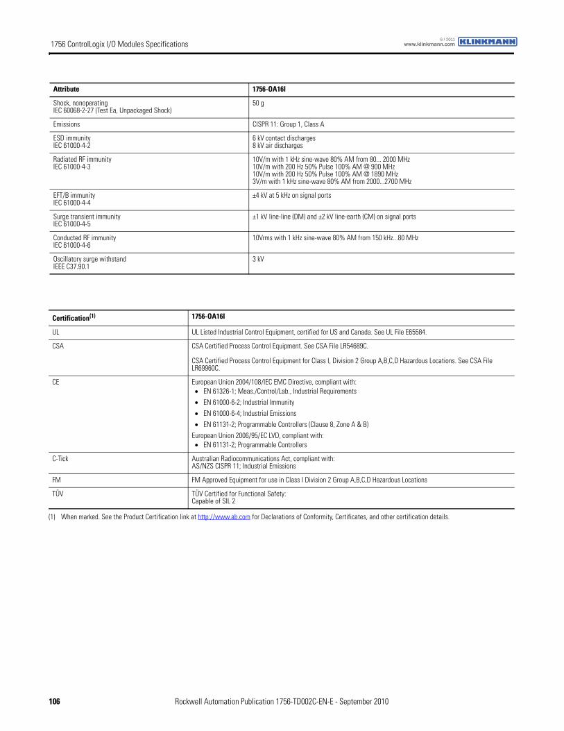
1756 ControlLogix I/O Modules Specifications www.klinkmann.com6 / 2011
Shock, nonoperatingIEC 60068-2-27 (Test Ea, Unpackaged Shock)
50 g
Emissions CISPR 11: Group 1, Class A
ESD immunityIEC 61000-4-2
6 kV contact discharges8 kV air discharges
Radiated RF immunityIEC 61000-4-3
10V/m with 1 kHz sine-wave 80% AM from 80... 2000 MHz10V/m with 200 Hz 50% Pulse 100% AM @ 900 MHz10V/m with 200 Hz 50% Pulse 100% AM @ 1890 MHz3V/m with 1 kHz sine-wave 80% AM from 2000...2700 MHz
EFT/B immunityIEC 61000-4-4
±4 kV at 5 kHz on signal ports
Surge transient immunityIEC 61000-4-5
±1 kV line-line (DM) and ±2 kV line-earth (CM) on signal ports
Conducted RF immunityIEC 61000-4-6
10Vrms with 1 kHz sine-wave 80% AM from 150 kHz...80 MHz
Oscillatory surge withstandIEEE C37.90.1
3 kV
Attribute 1756-OA16I
Certification(1) 1756-OA16I
UL UL Listed Industrial Control Equipment, certified for US and Canada. See UL File E65584.
CSA CSA Certified Process Control Equipment. See CSA File LR54689C.
CSA Certified Process Control Equipment for Class I, Division 2 Group A,B,C,D Hazardous Locations. See CSA File LR69960C.
CE European Union 2004/108/IEC EMC Directive, compliant with:• EN 61326-1; Meas./Control/Lab., Industrial Requirements
• EN 61000-6-2; Industrial Immunity
• EN 61000-6-4; Industrial Emissions
• EN 61131-2; Programmable Controllers (Clause 8, Zone A & B)
European Union 2006/95/EC LVD, compliant with:• EN 61131-2; Programmable Controllers
C-Tick Australian Radiocommunications Act, compliant with:AS/NZS CISPR 11; Industrial Emissions
FM FM Approved Equipment for use in Class I Division 2 Group A,B,C,D Hazardous Locations
TÜV TÜV Certified for Functional Safety:Capable of SIL 2
(1) When marked. See the Product Certification link at http://www.ab.com for Declarations of Conformity, Certificates, and other certification details.
106 Rockwell Automation Publication 1756-TD002C-EN-E - September 2010
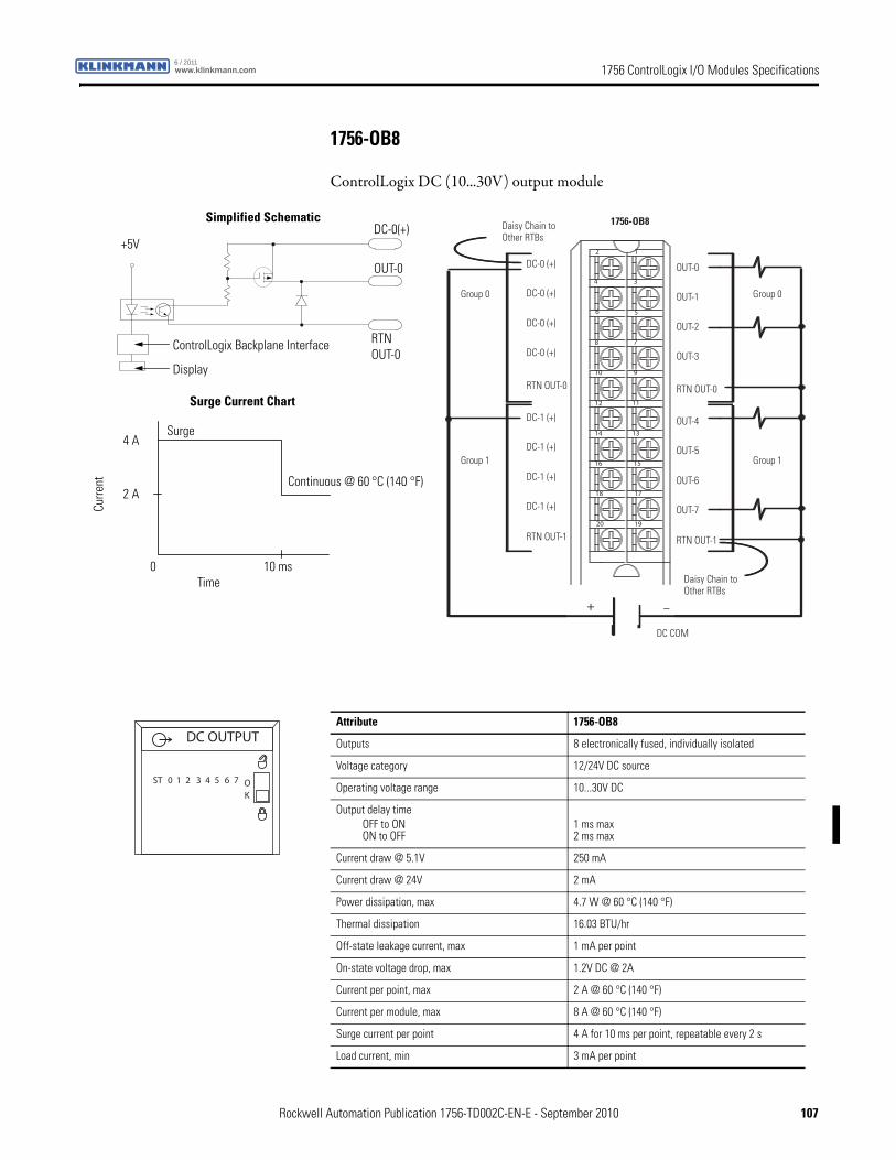
1756 ControlLogix I/O Modules Specificationswww.klinkmann.com6 / 2011
1756-OB8
ControlLogix DC (10...30V) output module
12
34
56
78
910
1112
1314
1516
1718
1920
+ –
Group 0Group 0
Group 1Group 1
Daisy Chain to Other RTBs
Daisy Chain to Other RTBs
DC COM
1756-OB8
DC-0 (+)
DC-0 (+)
DC-0 (+)
DC-0 (+)
DC-1 (+)
DC-1 (+)
DC-1 (+)
DC-1 (+)
RTN OUT-0
RTN OUT-1
OUT-0
OUT-1
OUT-2
OUT-3
OUT-4
OUT-5
OUT-6
OUT-7
RTN OUT-0
RTN OUT-1
RTNOUT-0
OUT-0
DC-0(+)
ControlLogix Backplane Interface
Display
Continuous @ 60 °C (140 °F)
Surge Current Chart
Simplified Schematic
Surge
+5V
Curre
nt
Time0 10 ms
2 A
4 A
Attribute 1756-OB8
Outputs 8 electronically fused, individually isolated
Voltage category 12/24V DC source
Operating voltage range 10...30V DC
Output delay timeOFF to ONON to OFF
1 ms max 2 ms max
Current draw @ 5.1V 250 mA
Current draw @ 24V 2 mA
Power dissipation, max 4.7 W @ 60 °C (140 °F)
Thermal dissipation 16.03 BTU/hr
Off-state leakage current, max 1 mA per point
On-state voltage drop, max 1.2V DC @ 2A
Current per point, max 2 A @ 60 °C (140 °F)
Current per module, max 8 A @ 60 °C (140 °F)
Surge current per point 4 A for 10 ms per point, repeatable every 2 s
Load current, min 3 mA per point
DC OUTPUT
ST 0 1 2 3 4 5 6 7 OK
Rockwell Automation Publication 1756-TD002C-EN-E - September 2010 107
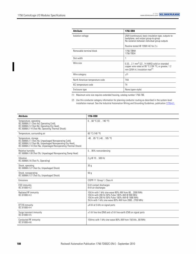
1756 ControlLogix I/O Modules Specifications www.klinkmann.com6 / 2011
Isolation voltage 250V (continuous), basic insulation type, outputs-to-backplane, and output group-to-groupNo isolation between individual group outputs
Routine tested @ 1350V AC for 2 s
Removable terminal block 1756-TBNH1756-TBSH
Slot width 1
Wire size 0.33... 2.1 mm2 (22...14 AWG) solid or stranded copper wire rated at 90 °C (194 °F), or greater, 1.2 mm (3/64 in.) insulation max(1)
Wire category 1(2)
North American temperature code T4A
IEC temperature code T4
Enclosure type None (open-style)
(1) Maximum wire size requires extended housing, catalog number 1756-TBE.
(2) Use this conductor category information for planning conductor routing as described in the system-level installation manual. See the Industrial Automation Wiring and Grounding Guidelines, publication 1770-4.1.
Attribute 1756-OB8
Attribute 1756-OB8
Temperature, operatingIEC 60068-2-1 (Test Ad, Operating Cold),IEC 60068-2-2 (Test Bd, Operating Dry Heat),IEC 60068-2-14 (Test Nb, Operating Thermal Shock)
0…60 °C (32…140 °F)
Temperature, surrounding air 60 °C (140 °F)
Temperature, storageIEC 60068-2-1 (Test Ab, Unpackaged Nonoperating Cold),IEC 60068-2-2 (Test Bb, Unpackaged Nonoperating Dry Heat),IEC 60068-2-14 (Test Na, Unpackaged Nonoperating Thermal Shock)
-40…85 °C (-40…185 °F)
Relative humidityIEC 60068-2-30 (Test Db, Unpackaged Nonoperating Damp Heat)
5…95% noncondensing
VibrationIEC 60068-2-6 (Test Fc, Operating)
2 g @ 10…500 Hz
Shock, operatingIEC 60068-2-27 (Test Ea, Unpackaged Shock)
30 g
Shock, nonoperatingIEC 60068-2-27 (Test Ea, Unpackaged Shock)
50 g
Emissions CISPR 11: Group 1, Class A
ESD immunityIEC 61000-4-2
6 kV contact discharges8 kV air discharges
Radiated RF immunityIEC 61000-4-3
10V/m with 1 kHz sine-wave 80% AM from 80... 2000 MHz10V/m with 200 Hz 50% Pulse 100% AM @ 900 MHz10V/m with 200 Hz 50% Pulse 100% AM @ 1890 MHz3V/m with 1 kHz sine-wave 80% AM from 2000...2700 MHz
EFT/B immunityIEC 61000-4-4
±4 kV at 5 kHz on signal ports
Surge transient immunityIEC 61000-4-5
±1 kV line-line (DM) and ±2 kV line-earth (CM) on signal ports
Conducted RF immunityIEC 61000-4-6
10Vrms with 1 kHz sine-wave 80% AM from 150 kHz...80 MHz
108 Rockwell Automation Publication 1756-TD002C-EN-E - September 2010

1756 ControlLogix I/O Modules Specificationswww.klinkmann.com6 / 2011
Certification(1) 1756-OB8
UL UL Listed Industrial Control Equipment, certified for US and Canada. See UL File E65584.
CSA CSA Certified Process Control Equipment. See CSA File LR54689C.
CSA Certified Process Control Equipment for Class I, Division 2 Group A,B,C,D Hazardous Locations. See CSA File LR69960C.
CE European Union 2004/108/IEC EMC Directive, compliant with:• EN 61326-1; Meas./Control/Lab., Industrial Requirements
• EN 61000-6-2; Industrial Immunity
• EN 61000-6-4; Industrial Emissions
• EN 61131-2; Programmable Controllers (Clause 8, Zone A & B)
European Union 2006/95/EC LVD, compliant with:• EN 61131-2; Programmable Controllers (Clause 11)
C-Tick Australian Radiocommunications Act, compliant with:AS/NZS CISPR 11; Industrial Emissions
Ex European Union 94/9/EC ATEX Directive, compliant with:• EN 60079-15; Potentially Explosive Atmospheres, Protection "n"
• EN 60079-0; General Requirements II 3 G Ex nA IIC T4 X
FM FM Approved Equipment for use in Class I Division 2 Group A,B,C,D Hazardous Locations
(1) When marked. See the Product Certification link at http://www.ab.com for Declarations of Conformity, Certificates, and other certification details.
Rockwell Automation Publication 1756-TD002C-EN-E - September 2010 109
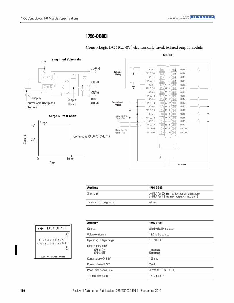
1756 ControlLogix I/O Modules Specifications www.klinkmann.com6 / 2011
1756-OB8EI
ControlLogix DC (10...30V) electronically-fused, isolated output module
1 2
3 4
5 6
7 8
01 9
21 11
41 31
61 51
81 71
02 91
22 12
42 32
62 52
82 72
03 92
23 13
43 33
63 53
+
+
-
-
+ –
DC-0 (+)
RTN OUT-0
DC-1 (+)
RTN OUT-1
DC-4 (+)
DC-2 (+)
RTN OUT-2
DC-3 (+)
RTN OUT-3
Not Used
RTN OUT-4DC-5 (+)
RTN OUT-5
DC-6 (+)
RTN OUT-6
DC-7 (+)
RTN OUT-7
Not Used
OUT-0
OUT-0
OUT-1
OUT-1
OUT-4
OUT-2
OUT-2
OUT-3
OUT-3
Not Used
OUT-4OUT-5
OUT-5
OUT-6
OUT-6
OUT-7
OUT-7
Not Used
DC COM
Isolated Wiring
1756-OB8EI
Daisy Chain toOther RTBs
Nonisolated Wiring
Daisy Chain toOther RTBs
Continuous @ 60 °C (140 °F)
ControlLogix Backplane Interface
Display OutputDevice
OUT-0
RTNOUT-0
DC-0(+)
OUT-0
Surge Current Chart
Simplified Schematic
Surge
+5V
Curre
nt
Time0 10 ms
2 A
4 A
Attribute 1756-OB8EI
Short trip > 4.5 A for 500 μs max (output on, then short)> 4.5 A for 1.5 ms max (output on into short)
Timestamp of diagnostics ±1 ms
Attribute 1756-OB8EI
Outputs 8 individually isolated
Voltage category 12/24V DC source
Operating voltage range 10...30V DC
Output delay timeOFF to ONON to OFF
1 ms max 5 ms max
Current draw @ 5.1V 165 mA
Current draw @ 24V 2 mA
Power dissipation, max 4.7 W @ 60 °C (140 °F)
Thermal dissipation 16.03 BTU/hr
DC OUTPUT
ST 0 1 2 3 4 5 6 7 OKFUSE
ELECTRONICALLY FUSED
0 1 2 3 4 5 6 7
110 Rockwell Automation Publication 1756-TD002C-EN-E - September 2010

1756 ControlLogix I/O Modules Specificationswww.klinkmann.com6 / 2011
Off-state leakage current, max 0.5 mA per point
On-state voltage drop, max 0.5V DC @ 2 A
Current per point, max 2 A @ 60 °C (140 °F)
Current per module, max 10 A @ 60 °C (140 °F)16 A @ 55 °C (131°F) linear derating
Surge current per point 4 A for 10 ms each, repeatable every 1 s @ 60 °C (140 °F)
Load current, min 2 mA
Isolation voltage 250V (continuous), basic insulation type, outputs-to-backplane, and output-to-output
Routine tested @ 1350V AC for 2 s
Removable terminal block 1756-TBCH1756-TBS6H
Slot width 1
Wire size 0.33... 2.1 mm2 (22...14 AWG) solid or stranded copper wire rated at 90 °C (194 °F), or greater, 1.2 mm (3/64 in.) insulation max(1)
Wire category 1(2)
North American temperature code T4A
IEC temperature code T4
Enclosure type None (open-style)
(1) Maximum wire size requires extended housing, catalog number 1756-TBE.
(2) Use this conductor category information for planning conductor routing as described in the system-level installation manual. See the Industrial Automation Wiring and Grounding Guidelines, publication 1770-4.1.
Attribute 1756-OB8EI
Attribute 1756-OB8EI
Temperature, operatingIEC 60068-2-1 (Test Ad, Operating Cold),IEC 60068-2-2 (Test Bd, Operating Dry Heat),IEC 60068-2-14 (Test Nb, Operating Thermal Shock)
0…60 °C (32…140 °F)
Temperature, surrounding air 60 °C (140 °F)
Temperature, storageIEC 60068-2-1 (Test Ab, Unpackaged Nonoperating Cold),IEC 60068-2-2 (Test Bb, Unpackaged Nonoperating Dry Heat),IEC 60068-2-14 (Test Na, Unpackaged Nonoperating Thermal Shock)
-40…85 °C (-40…185 °F)
Relative humidityIEC 60068-2-30 (Test Db, Unpackaged Nonoperating Damp Heat)
5…95% noncondensing
VibrationIEC 60068-2-6 (Test Fc, Operating)
2 g @ 10…500 Hz
Shock, operatingIEC 60068-2-27 (Test Ea, Unpackaged Shock)
30 g
Shock, nonoperatingIEC 60068-2-27 (Test Ea, Unpackaged Shock)
50 g
Emissions CISPR 11: Group 1, Class A
ESD immunityIEC 61000-4-2
6 kV contact discharges8 kV air discharges
Radiated RF immunityIEC 61000-4-3
10V/m with 1 kHz sine-wave 80% AM from 80... 2000 MHz10V/m with 200 Hz 50% Pulse 100% AM @ 900 MHz10V/m with 200 Hz 50% Pulse 100% AM @ 1890 MHz3V/m with 1 kHz sine-wave 80% AM from 2000...2700 MHz
Rockwell Automation Publication 1756-TD002C-EN-E - September 2010 111
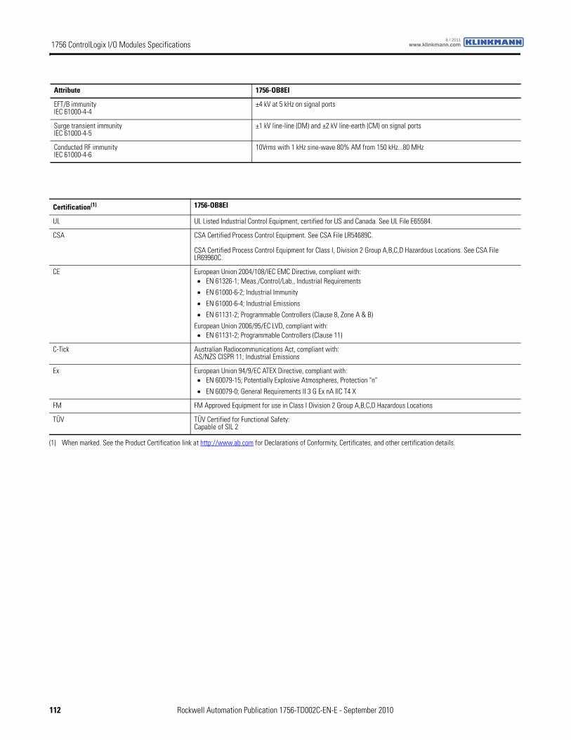
1756 ControlLogix I/O Modules Specifications www.klinkmann.com6 / 2011
EFT/B immunityIEC 61000-4-4
±4 kV at 5 kHz on signal ports
Surge transient immunityIEC 61000-4-5
±1 kV line-line (DM) and ±2 kV line-earth (CM) on signal ports
Conducted RF immunityIEC 61000-4-6
10Vrms with 1 kHz sine-wave 80% AM from 150 kHz...80 MHz
Attribute 1756-OB8EI
Certification(1) 1756-OB8EI
UL UL Listed Industrial Control Equipment, certified for US and Canada. See UL File E65584.
CSA CSA Certified Process Control Equipment. See CSA File LR54689C.
CSA Certified Process Control Equipment for Class I, Division 2 Group A,B,C,D Hazardous Locations. See CSA File LR69960C.
CE European Union 2004/108/IEC EMC Directive, compliant with:• EN 61326-1; Meas./Control/Lab., Industrial Requirements
• EN 61000-6-2; Industrial Immunity
• EN 61000-6-4; Industrial Emissions
• EN 61131-2; Programmable Controllers (Clause 8, Zone A & B)
European Union 2006/95/EC LVD, compliant with:• EN 61131-2; Programmable Controllers (Clause 11)
C-Tick Australian Radiocommunications Act, compliant with:AS/NZS CISPR 11; Industrial Emissions
Ex European Union 94/9/EC ATEX Directive, compliant with:• EN 60079-15; Potentially Explosive Atmospheres, Protection "n"
• EN 60079-0; General Requirements II 3 G Ex nA IIC T4 X
FM FM Approved Equipment for use in Class I Division 2 Group A,B,C,D Hazardous Locations
TÜV TÜV Certified for Functional Safety:Capable of SIL 2
(1) When marked. See the Product Certification link at http://www.ab.com for Declarations of Conformity, Certificates, and other certification details.
112 Rockwell Automation Publication 1756-TD002C-EN-E - September 2010
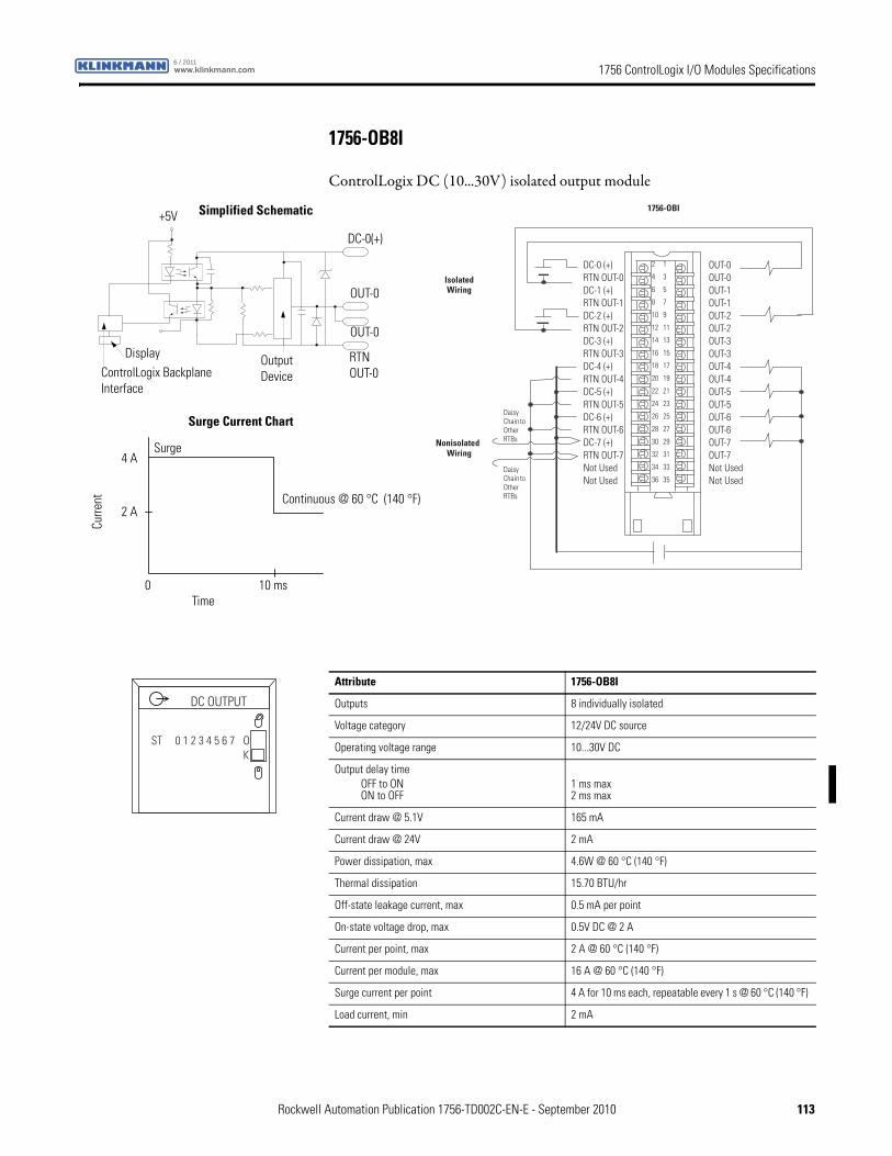
1756 ControlLogix I/O Modules Specificationswww.klinkmann.com6 / 2011
1756-OB8I
ControlLogix DC (10...30V) isolated output module
DC-0 (+) RTN OUT-0 DC-1 (+) RTN OUT-1 DC-2 (+) RTN OUT-2 DC-3 (+) RTN OUT-3 DC-4 (+) RTN OUT-4 DC-5 (+) RTN OUT-5 DC-6 (+) RTN OUT-6 DC-7 (+) RTN OUT-7 Not Used Not Used
OUT-0 OUT-0 OUT-1 OUT-1 OUT-2 OUT-2 OUT-3 OUT-3 OUT-4 OUT-4 OUT-5 OUT-5 OUT-6 OUT-6 OUT-7 OUT-7 Not Used Not Used
2
4
6
8
10
12
14
16
18
20
22
24
26
28
30
32
34
36
1
3
5
7
9
11
13
15
17
19
21
23
25
27
29
31
33
35Daisy Chain to Other RTBs
Daisy Chain to Other RTBs
1756-OBI
Isolated Wiring
Nonisolated Wiring
Continuous @ 60 °C (140 °F)
ControlLogix Backplane Interface
Display OutputDevice
OUT-0
RTNOUT-0
DC-0(+)
OUT-0
Surge Current Chart
Simplified Schematic
Surge
+5V
Curre
nt
Time0 10 ms
2 A
4 A
Attribute 1756-OB8I
Outputs 8 individually isolated
Voltage category 12/24V DC source
Operating voltage range 10...30V DC
Output delay timeOFF to ONON to OFF
1 ms max 2 ms max
Current draw @ 5.1V 165 mA
Current draw @ 24V 2 mA
Power dissipation, max 4.6W @ 60 °C (140 °F)
Thermal dissipation 15.70 BTU/hr
Off-state leakage current, max 0.5 mA per point
On-state voltage drop, max 0.5V DC @ 2 A
Current per point, max 2 A @ 60 °C (140 °F)
Current per module, max 16 A @ 60 °C (140 °F)
Surge current per point 4 A for 10 ms each, repeatable every 1 s @ 60 °C (140 °F)
Load current, min 2 mA
DC OUTPUT
ST 0 1 2 3 4 5 6 7 OK
Rockwell Automation Publication 1756-TD002C-EN-E - September 2010 113

1756 ControlLogix I/O Modules Specifications www.klinkmann.com6 / 2011
Isolation voltage 250V (continuous), reinforced insulation type, outputs-to-backplane250V (continuous), basic insulation type, output-to-output
Routine tested @ 1350V AC for 2 s
Removable terminal block 1756-TBCH1756-TBS6H
Slot width 1
Wire size 0.33... 2.1 mm2 (22...14 AWG) solid or stranded copper wire rated at 90 °C (194 °F), or greater, 1.2 mm (3/64 in.) insulation max(1)
Wire category 1(2)
North American temperature code T4A
Enclosure type None (open-style)
(1) Maximum wire size requires extended housing, catalog number 1756-TBE.
(2) Use this conductor category information for planning conductor routing as described in the system-level installation manual. See the Industrial Automation Wiring and Grounding Guidelines, publication 1770-4.1.
Attribute 1756-OB8I
Attribute 1756-OB8I
Temperature, operatingIEC 60068-2-1 (Test Ad, Operating Cold),IEC 60068-2-2 (Test Bd, Operating Dry Heat),IEC 60068-2-14 (Test Nb, Operating Thermal Shock)
0…60 °C (32…140 °F)
Temperature, surrounding air 60 °C (140 °F)
Temperature, storageIEC 60068-2-1 (Test Ab, Unpackaged Nonoperating Cold),IEC 60068-2-2 (Test Bb, Unpackaged Nonoperating Dry Heat),IEC 60068-2-14 (Test Na, Unpackaged Nonoperating Thermal Shock)
-40…85 °C (-40…185 °F)
Relative humidityIEC 60068-2-30 (Test Db, Unpackaged Nonoperating Damp Heat)
5…95% noncondensing
VibrationIEC 60068-2-6 (Test Fc, Operating)
2 g @ 10…500 Hz
Shock, operatingIEC 60068-2-27 (Test Ea, Unpackaged Shock)
30 g
Shock, nonoperatingIEC 60068-2-27 (Test Ea, Unpackaged Shock)
50 g
Emissions CISPR 11: Group 1, Class A
ESD immunityIEC 61000-4-2
6 kV contact discharges8k V air discharges
Radiated RF immunityIEC 61000-4-3
10V/m with 1 kHz sine-wave 80% AM from 80... 2000 MHz10V/m with 200 Hz 50% Pulse 100% AM @ 900 MHz10V/m with 200 Hz 50% Pulse 100% AM @ 1890 MHz3V/m with 1k Hz sine-wave 80% AM from 2000...2700 MHz
EFT/B immunityIEC 61000-4-4
±4 kV at 5 kHz on signal ports
Surge transient immunityIEC 61000-4-5
±1 kV line-line (DM) and ±2 kV line-earth (CM) on signal ports
Conducted RF immunityIEC 61000-4-6
10Vrms with 1 kHz sine-wave 80% AM from 150 kHz...80 MHz
114 Rockwell Automation Publication 1756-TD002C-EN-E - September 2010
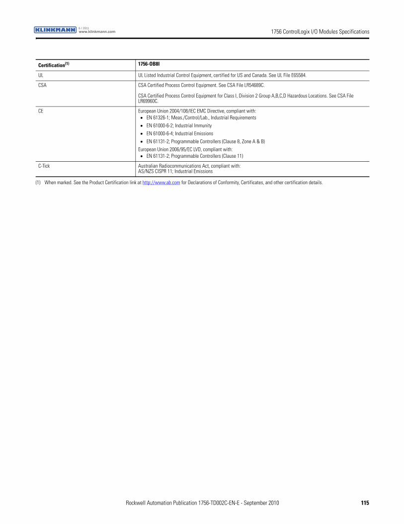
1756 ControlLogix I/O Modules Specificationswww.klinkmann.com6 / 2011
Certification(1) 1756-OB8I
UL UL Listed Industrial Control Equipment, certified for US and Canada. See UL File E65584.
CSA CSA Certified Process Control Equipment. See CSA File LR54689C.
CSA Certified Process Control Equipment for Class I, Division 2 Group A,B,C,D Hazardous Locations. See CSA File LR69960C.
CE European Union 2004/108/IEC EMC Directive, compliant with:• EN 61326-1; Meas./Control/Lab., Industrial Requirements
• EN 61000-6-2; Industrial Immunity
• EN 61000-6-4; Industrial Emissions
• EN 61131-2; Programmable Controllers (Clause 8, Zone A & B)
European Union 2006/95/EC LVD, compliant with:• EN 61131-2; Programmable Controllers (Clause 11)
C-Tick Australian Radiocommunications Act, compliant with:AS/NZS CISPR 11; Industrial Emissions
(1) When marked. See the Product Certification link at http://www.ab.com for Declarations of Conformity, Certificates, and other certification details.
Rockwell Automation Publication 1756-TD002C-EN-E - September 2010 115
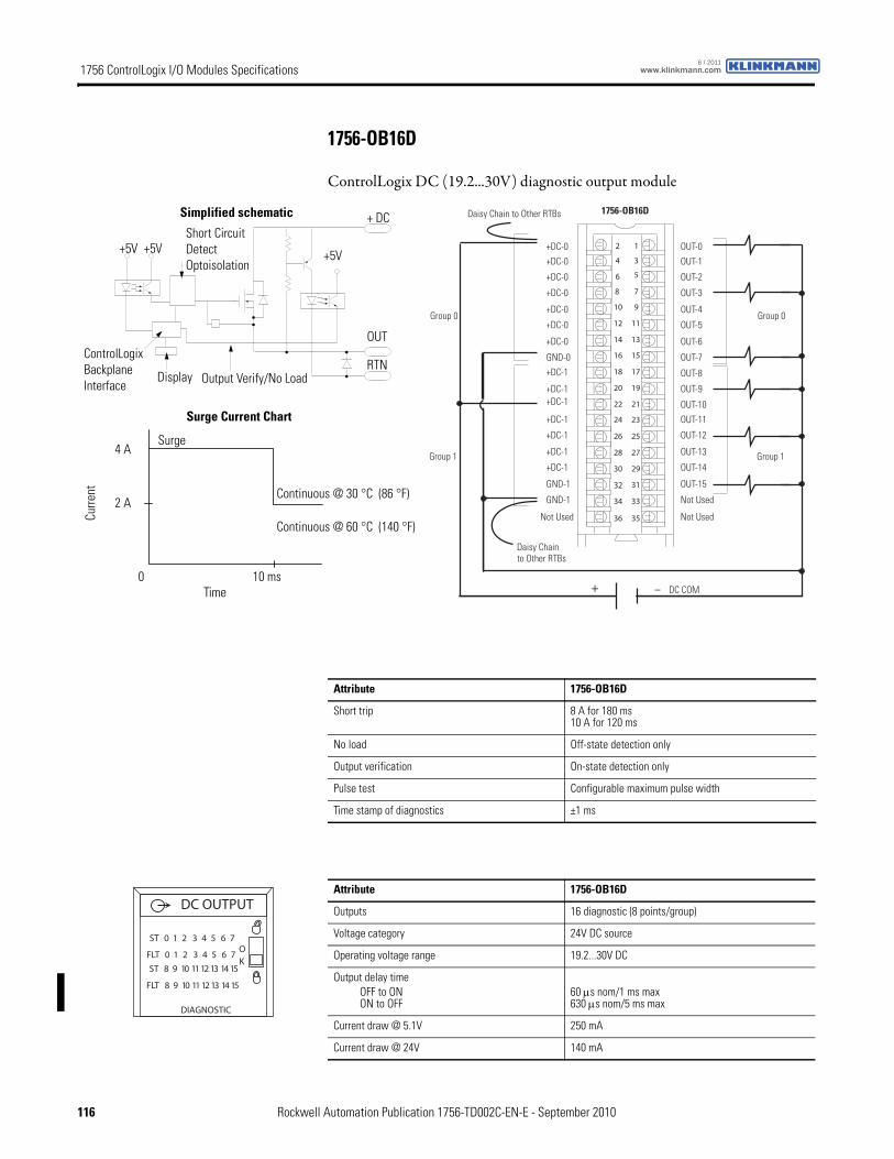
1756 ControlLogix I/O Modules Specifications www.klinkmann.com6 / 2011
1756-OB16D
ControlLogix DC (19.2...30V) diagnostic output module
12
34
56
78
910
1112
1314
1516
1718
1920
2122
2324
2526
2728
2930
3132
3334
3536
+ –
Daisy Chain to Other RTBs
DC COM
0 puorG0 puorG
1 puorG1 puorG
1756-OB16D
+DC-0
+DC-0
+DC-0
+DC-0
+DC-1
+DC-0
+DC-0
+DC-0
GND-0
Not Used
+DC-1+DC-1
+DC-1
+DC-1
+DC-1
+DC-1
GND-1
GND-1
OUT-0
OUT-1
OUT-2
OUT-3
OUT-8
OUT-4
OUT-5
OUT-6
OUT-7
Not Used
OUT-9
OUT-10
OUT-11
OUT-12
OUT-13
OUT-14
OUT-15
Not Used
Daisy Chain to Other RTBs
ControlLogix Backplane Interface
Display
+5VShort Circuit Detect Optoisolation
+5V
+ DC
OUT
RTNOutput Verify/No Load
Surge Current Chart
Continuous @ 30 °C (86 °F)
Simplified schematic
Continuous @ 60 °C (140 °F)
Surge
+5V
Curre
nt
Time0 10 ms
2 A
4 A
Attribute 1756-OB16D
Short trip 8 A for 180 ms10 A for 120 ms
No load Off-state detection only
Output verification On-state detection only
Pulse test Configurable maximum pulse width
Time stamp of diagnostics ±1 ms
Attribute 1756-OB16D
Outputs 16 diagnostic (8 points/group)
Voltage category 24V DC source
Operating voltage range 19.2...30V DC
Output delay timeOFF to ONON to OFF
60 μs nom/1 ms max 630 μs nom/5 ms max
Current draw @ 5.1V 250 mA
Current draw @ 24V 140 mA
ST 0 1 2 3 4 5 6 7
FLT 0 1 2 3 4 5 6 7
DIAGNOSTIC
ST 8 9 10 11 12 13 14 15
FLT 8 9 10 11 12 13 14 15
DC OUTPUT
OK
116 Rockwell Automation Publication 1756-TD002C-EN-E - September 2010
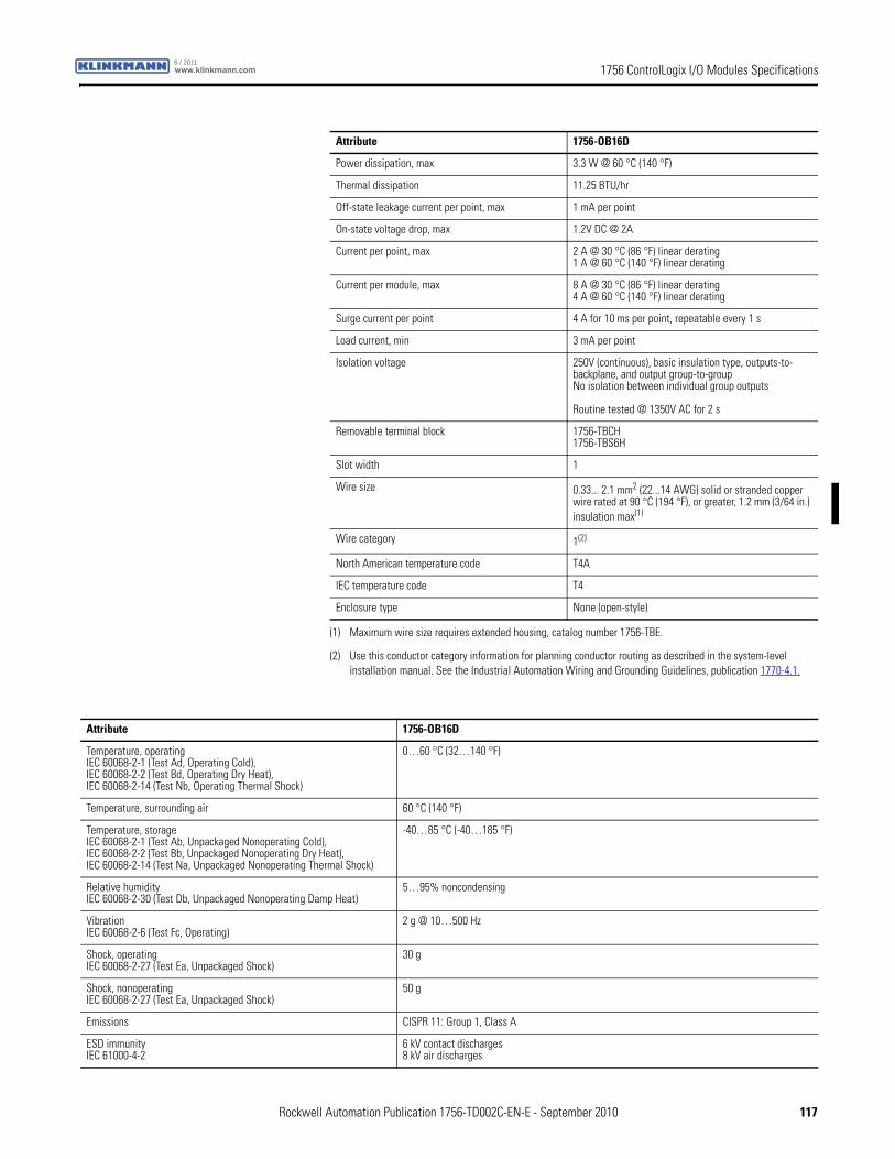
1756 ControlLogix I/O Modules Specificationswww.klinkmann.com6 / 2011
Power dissipation, max 3.3 W @ 60 °C (140 °F)
Thermal dissipation 11.25 BTU/hr
Off-state leakage current per point, max 1 mA per point
On-state voltage drop, max 1.2V DC @ 2A
Current per point, max 2 A @ 30 °C (86 °F) linear derating1 A @ 60 °C (140 °F) linear derating
Current per module, max 8 A @ 30 °C (86 °F) linear derating4 A @ 60 °C (140 °F) linear derating
Surge current per point 4 A for 10 ms per point, repeatable every 1 s
Load current, min 3 mA per point
Isolation voltage 250V (continuous), basic insulation type, outputs-to-backplane, and output group-to-groupNo isolation between individual group outputs
Routine tested @ 1350V AC for 2 s
Removable terminal block 1756-TBCH1756-TBS6H
Slot width 1
Wire size 0.33... 2.1 mm2 (22...14 AWG) solid or stranded copper wire rated at 90 °C (194 °F), or greater, 1.2 mm (3/64 in.) insulation max(1)
Wire category 1(2)
North American temperature code T4A
IEC temperature code T4
Enclosure type None (open-style)
(1) Maximum wire size requires extended housing, catalog number 1756-TBE.
(2) Use this conductor category information for planning conductor routing as described in the system-level installation manual. See the Industrial Automation Wiring and Grounding Guidelines, publication 1770-4.1.
Attribute 1756-OB16D
Attribute 1756-OB16D
Temperature, operatingIEC 60068-2-1 (Test Ad, Operating Cold),IEC 60068-2-2 (Test Bd, Operating Dry Heat),IEC 60068-2-14 (Test Nb, Operating Thermal Shock)
0…60 °C (32…140 °F)
Temperature, surrounding air 60 °C (140 °F)
Temperature, storageIEC 60068-2-1 (Test Ab, Unpackaged Nonoperating Cold),IEC 60068-2-2 (Test Bb, Unpackaged Nonoperating Dry Heat),IEC 60068-2-14 (Test Na, Unpackaged Nonoperating Thermal Shock)
-40…85 °C (-40…185 °F)
Relative humidityIEC 60068-2-30 (Test Db, Unpackaged Nonoperating Damp Heat)
5…95% noncondensing
VibrationIEC 60068-2-6 (Test Fc, Operating)
2 g @ 10…500 Hz
Shock, operatingIEC 60068-2-27 (Test Ea, Unpackaged Shock)
30 g
Shock, nonoperatingIEC 60068-2-27 (Test Ea, Unpackaged Shock)
50 g
Emissions CISPR 11: Group 1, Class A
ESD immunityIEC 61000-4-2
6 kV contact discharges8 kV air discharges
Rockwell Automation Publication 1756-TD002C-EN-E - September 2010 117
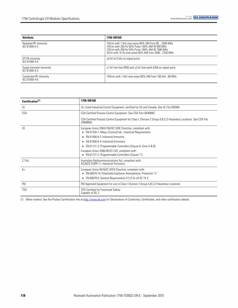
1756 ControlLogix I/O Modules Specifications www.klinkmann.com6 / 2011
Radiated RF immunityIEC 61000-4-3
10V/m with 1 kHz sine-wave 80% AM from 80... 2000 MHz10V/m with 200 Hz 50% Pulse 100% AM @ 900 MHz10V/m with 200 Hz 50% Pulse 100% AM @ 1890 MHz3V/m with 1k Hz sine-wave 80% AM from 2000...2700 MHz
EFT/B immunityIEC 61000-4-4
±4 kV at 5 kHz on signal ports
Surge transient immunityIEC 61000-4-5
±1 kV line-line (DM) and ±2 kV line-earth (CM) on signal ports
Conducted RF immunityIEC 61000-4-6
10Vrms with 1 kHz sine-wave 80% AM from 150 kHz...80 MHz
Attribute 1756-OB16D
Certification(1) 1756-OB16D
UL UL Listed Industrial Control Equipment, certified for US and Canada. See UL File E65584.
CSA CSA Certified Process Control Equipment. See CSA File LR54689C.
CSA Certified Process Control Equipment for Class I, Division 2 Group A,B,C,D Hazardous Locations. See CSA File LR69960C.
CE European Union 2004/108/IEC EMC Directive, compliant with:• EN 61326-1; Meas./Control/Lab., Industrial Requirements
• EN 61000-6-2; Industrial Immunity
• EN 61000-6-4; Industrial Emissions
• EN 61131-2; Programmable Controllers (Clause 8, Zone A & B)
European Union 2006/95/EC LVD, compliant with:• EN 61131-2; Programmable Controllers (Clause 11)
C-Tick Australian Radiocommunications Act, compliant with:AS/NZS CISPR 11; Industrial Emissions
Ex European Union 94/9/EC ATEX Directive, compliant with:• EN 60079-15; Potentially Explosive Atmospheres, Protection "n"
• EN 60079-0; General Requirements II 3 G Ex nA IIC T4 X
FM FM Approved Equipment for use in Class I Division 2 Group A,B,C,D Hazardous Locations
TÜV TÜV Certified for Functional Safety:Capable of SIL 2
(1) When marked. See the Product Certification link at http://www.ab.com for Declarations of Conformity, Certificates, and other certification details.
118 Rockwell Automation Publication 1756-TD002C-EN-E - September 2010
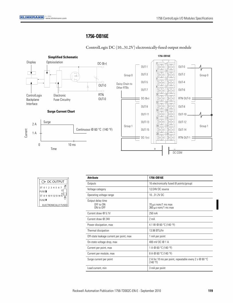
1756 ControlLogix I/O Modules Specificationswww.klinkmann.com6 / 2011
1756-OB16E
ControlLogix DC (10...31.2V) electronically-fused output module
12
34
56
78
910
1112
1314
1516
1718
1920
+ –
Daisy Chain to Other RTBs
Group 0Group 0
Group 1Group 1
DC COM
OUT-1
OUT-3
OUT-5
OUT-7
OUT-9
OUT-11
OUT-13
OUT-15
DC-0(+)
DC-1(+)
OUT-0
OUT-2
OUT-4
OUT-6
OUT-8
OUT-10
OUT-12
OUT-14
RTN OUT-0
RTN OUT-1
1756-OB16E
ControlLogix Backplane Interface
Electronic Fuse Circuitry
Continuous @ 60 °C (140 °F)
Display Optoisolation
RTNOUT-0
OUT-0
DC-0(+)
Surge Current Chart
Simplified Schematic
Surge
Curre
nt
Time0 10 ms
1 A
2 A
Attribute 1756-OB16E
Outputs 16 electronically fused (8 points/group)
Voltage category 12/24V DC source
Operating voltage range 10...31.2V DC
Output delay timeOFF to ONON to OFF
70 μs nom/1 ms max360 μs nom/1 ms max
Current draw @ 5.1V 250 mA
Current draw @ 24V 2 mA
Power dissipation, max 4.1 W @ 60 °C (140 °F)
Thermal dissipation 13.98 BTU/hr
Off-state leakage current per point, max 1 mA per point
On-state voltage drop, max 400 mV DC @ 1 A
Current per point, max 1 A @ 60 °C (140 °F)
Current per module, max 8 A @ 60 °C (140 °F)
Surge current per point 2 A for 10 ms per point, repeatable every 2 s @ 60 °C (140 °F)
Load current, min 3 mA per point
DC OUTPUT
ST 0 1 2 3 4 5 6 7
ST 8 9 10 11 12 13 14 15
OK
FUSE
FUSE
ELECTRONICALLY FUSED
Rockwell Automation Publication 1756-TD002C-EN-E - September 2010 119
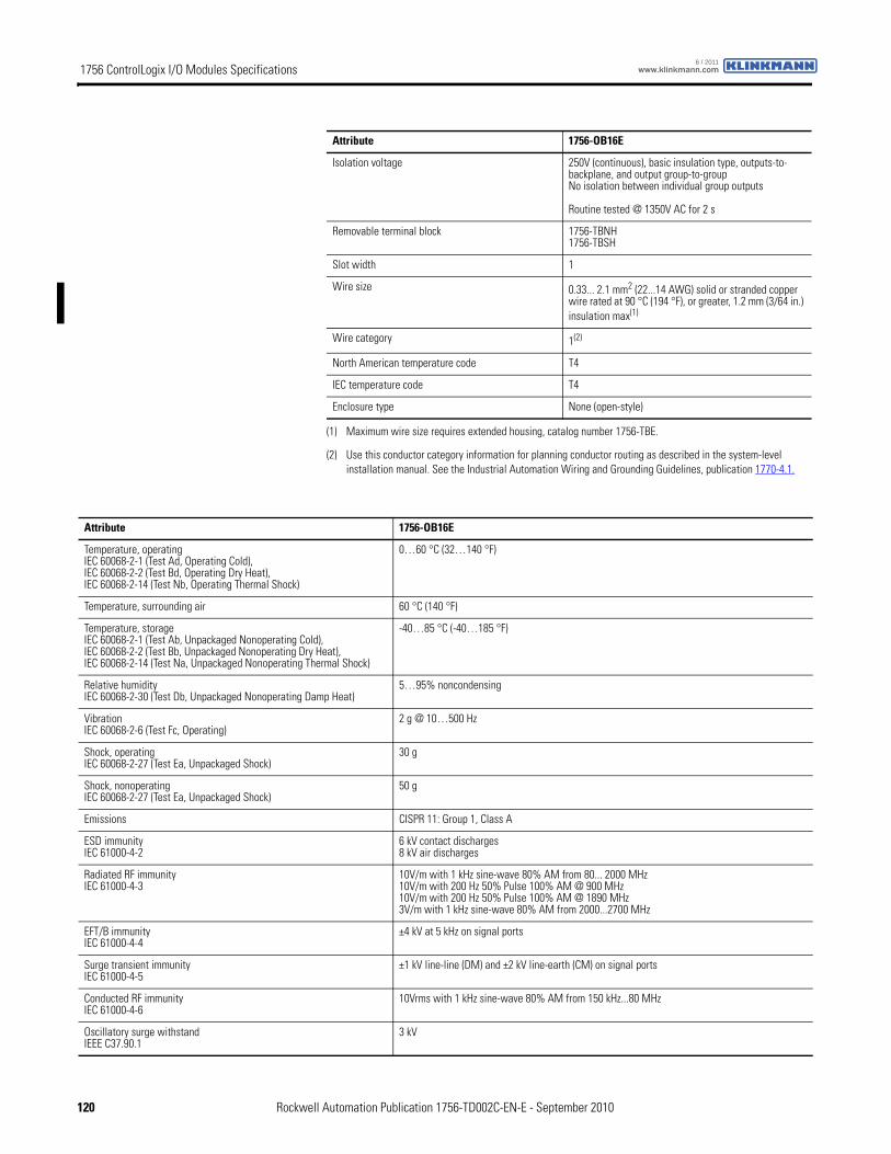
1756 ControlLogix I/O Modules Specifications www.klinkmann.com6 / 2011
Isolation voltage 250V (continuous), basic insulation type, outputs-to-backplane, and output group-to-groupNo isolation between individual group outputs
Routine tested @ 1350V AC for 2 s
Removable terminal block 1756-TBNH1756-TBSH
Slot width 1
Wire size 0.33... 2.1 mm2 (22...14 AWG) solid or stranded copper wire rated at 90 °C (194 °F), or greater, 1.2 mm (3/64 in.) insulation max(1)
Wire category 1(2)
North American temperature code T4
IEC temperature code T4
Enclosure type None (open-style)
(1) Maximum wire size requires extended housing, catalog number 1756-TBE.
(2) Use this conductor category information for planning conductor routing as described in the system-level installation manual. See the Industrial Automation Wiring and Grounding Guidelines, publication 1770-4.1.
Attribute 1756-OB16E
Attribute 1756-OB16E
Temperature, operatingIEC 60068-2-1 (Test Ad, Operating Cold),IEC 60068-2-2 (Test Bd, Operating Dry Heat),IEC 60068-2-14 (Test Nb, Operating Thermal Shock)
0…60 °C (32…140 °F)
Temperature, surrounding air 60 °C (140 °F)
Temperature, storageIEC 60068-2-1 (Test Ab, Unpackaged Nonoperating Cold),IEC 60068-2-2 (Test Bb, Unpackaged Nonoperating Dry Heat),IEC 60068-2-14 (Test Na, Unpackaged Nonoperating Thermal Shock)
-40…85 °C (-40…185 °F)
Relative humidityIEC 60068-2-30 (Test Db, Unpackaged Nonoperating Damp Heat)
5…95% noncondensing
VibrationIEC 60068-2-6 (Test Fc, Operating)
2 g @ 10…500 Hz
Shock, operatingIEC 60068-2-27 (Test Ea, Unpackaged Shock)
30 g
Shock, nonoperatingIEC 60068-2-27 (Test Ea, Unpackaged Shock)
50 g
Emissions CISPR 11: Group 1, Class A
ESD immunityIEC 61000-4-2
6 kV contact discharges8 kV air discharges
Radiated RF immunityIEC 61000-4-3
10V/m with 1 kHz sine-wave 80% AM from 80... 2000 MHz10V/m with 200 Hz 50% Pulse 100% AM @ 900 MHz10V/m with 200 Hz 50% Pulse 100% AM @ 1890 MHz3V/m with 1 kHz sine-wave 80% AM from 2000...2700 MHz
EFT/B immunityIEC 61000-4-4
±4 kV at 5 kHz on signal ports
Surge transient immunityIEC 61000-4-5
±1 kV line-line (DM) and ±2 kV line-earth (CM) on signal ports
Conducted RF immunityIEC 61000-4-6
10Vrms with 1 kHz sine-wave 80% AM from 150 kHz...80 MHz
Oscillatory surge withstandIEEE C37.90.1
3 kV
120 Rockwell Automation Publication 1756-TD002C-EN-E - September 2010
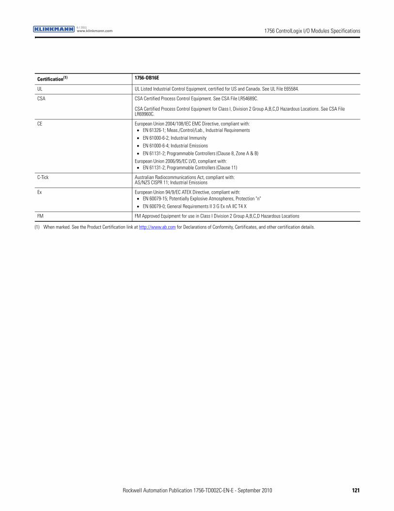
1756 ControlLogix I/O Modules Specificationswww.klinkmann.com6 / 2011
Certification(1) 1756-OB16E
UL UL Listed Industrial Control Equipment, certified for US and Canada. See UL File E65584.
CSA CSA Certified Process Control Equipment. See CSA File LR54689C.
CSA Certified Process Control Equipment for Class I, Division 2 Group A,B,C,D Hazardous Locations. See CSA File LR69960C.
CE European Union 2004/108/IEC EMC Directive, compliant with:• EN 61326-1; Meas./Control/Lab., Industrial Requirements
• EN 61000-6-2; Industrial Immunity
• EN 61000-6-4; Industrial Emissions
• EN 61131-2; Programmable Controllers (Clause 8, Zone A & B)
European Union 2006/95/EC LVD, compliant with:• EN 61131-2; Programmable Controllers (Clause 11)
C-Tick Australian Radiocommunications Act, compliant with:AS/NZS CISPR 11; Industrial Emissions
Ex European Union 94/9/EC ATEX Directive, compliant with:• EN 60079-15; Potentially Explosive Atmospheres, Protection "n"
• EN 60079-0; General Requirements II 3 G Ex nA IIC T4 X
FM FM Approved Equipment for use in Class I Division 2 Group A,B,C,D Hazardous Locations
(1) When marked. See the Product Certification link at http://www.ab.com for Declarations of Conformity, Certificates, and other certification details.
Rockwell Automation Publication 1756-TD002C-EN-E - September 2010 121
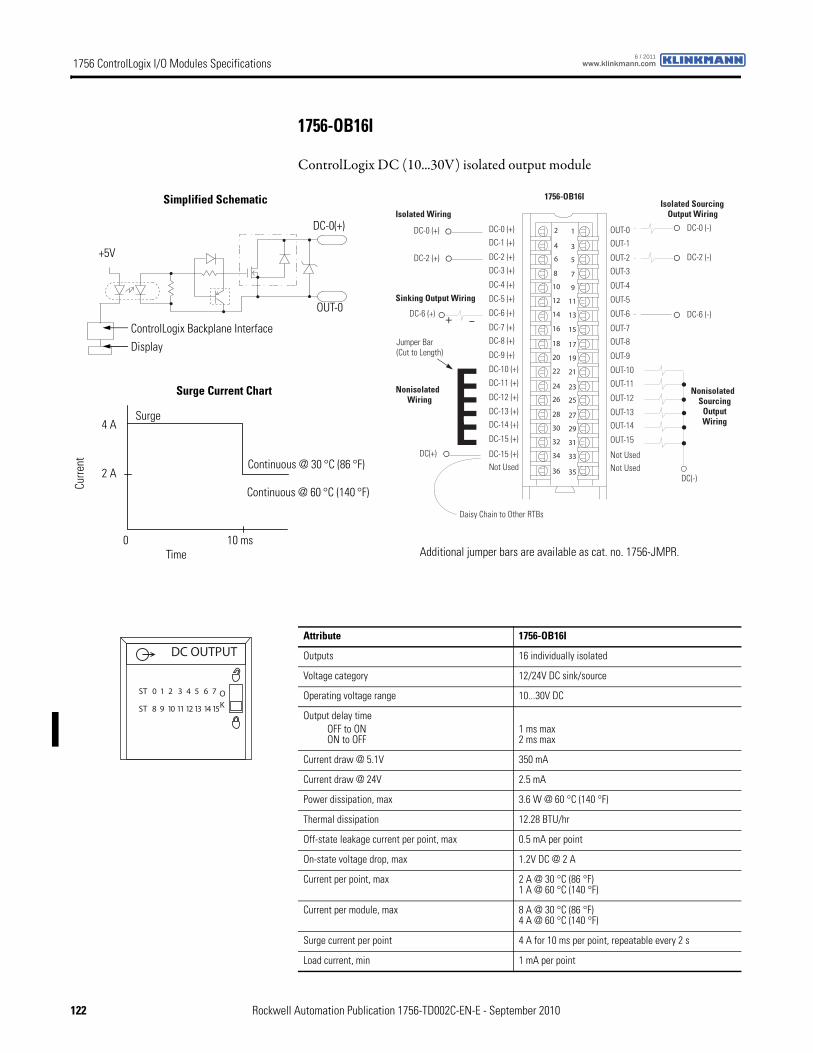
1756 ControlLogix I/O Modules Specifications www.klinkmann.com6 / 2011
1756-OB16I
ControlLogix DC (10...30V) isolated output module
12
34
56
78
910
1112
1314
1516
1718
1920
2122
2324
2526
2728
2930
3132
3334
3536
+ –
Nonisolated Wiring
Isolated Wiring
Daisy Chain to Other RTBs
1756-OB16I
DC-0 (+)DC-1 (+)
DC-2 (+)
DC-3 (+)
DC-8 (+)
DC-4 (+)
DC-5 (+)
DC-6 (+)
DC-7 (+)
Not Used
DC-9 (+)
DC-10 (+)
DC-11 (+)
DC-12 (+)
DC-13 (+)DC-14 (+)
DC-15 (+)
DC-15 (+)
OUT-0OUT-1
OUT-2
OUT-3
OUT-8
OUT-4
OUT-5
OUT-6
OUT-7
Not Used
OUT-9
OUT-10
OUT-11
OUT-12
OUT-13OUT-14
OUT-15
Not Used
DC-0 (+)
DC(+)
Jumper Bar (Cut to Length)
DC-2 (+)
DC-6 (+)
Sinking Output Wiring
Nonisolated Sourcing
Output Wiring
Isolated Sourcing Output Wiring
DC-0 (-)
DC-2 (-)
DC-6 (-)
DC(-)
ControlLogix Backplane Interface
Continuous @ 60 °C (140 °F)
Display
Surge Current Chart
Simplified Schematic
Surge
Continuous @ 30 °C (86 °F)
OUT-0
DC-0(+)
Curre
nt
Time0 10 ms
2 A
4 A
+5V
Additional jumper bars are available as cat. no. 1756-JMPR.
Attribute 1756-OB16I
Outputs 16 individually isolated
Voltage category 12/24V DC sink/source
Operating voltage range 10...30V DC
Output delay timeOFF to ONON to OFF
1 ms max 2 ms max
Current draw @ 5.1V 350 mA
Current draw @ 24V 2.5 mA
Power dissipation, max 3.6 W @ 60 °C (140 °F)
Thermal dissipation 12.28 BTU/hr
Off-state leakage current per point, max 0.5 mA per point
On-state voltage drop, max 1.2V DC @ 2 A
Current per point, max 2 A @ 30 °C (86 °F)1 A @ 60 °C (140 °F)
Current per module, max 8 A @ 30 °C (86 °F)4 A @ 60 °C (140 °F)
Surge current per point 4 A for 10 ms per point, repeatable every 2 s
Load current, min 1 mA per point
DC OUTPUT
ST 0 1 2 3 4 5 6 7
ST 8 9 10 11 12 13 14 15
OK
122 Rockwell Automation Publication 1756-TD002C-EN-E - September 2010
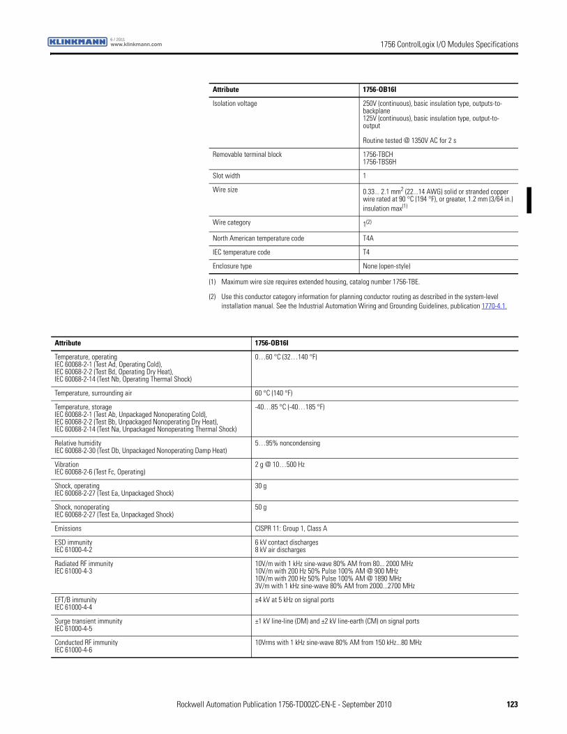
1756 ControlLogix I/O Modules Specificationswww.klinkmann.com6 / 2011
Isolation voltage 250V (continuous), basic insulation type, outputs-to-backplane125V (continuous), basic insulation type, output-to-output
Routine tested @ 1350V AC for 2 s
Removable terminal block 1756-TBCH1756-TBS6H
Slot width 1
Wire size 0.33... 2.1 mm2 (22...14 AWG) solid or stranded copper wire rated at 90 °C (194 °F), or greater, 1.2 mm (3/64 in.) insulation max(1)
Wire category 1(2)
North American temperature code T4A
IEC temperature code T4
Enclosure type None (open-style)
(1) Maximum wire size requires extended housing, catalog number 1756-TBE.
(2) Use this conductor category information for planning conductor routing as described in the system-level installation manual. See the Industrial Automation Wiring and Grounding Guidelines, publication 1770-4.1.
Attribute 1756-OB16I
Attribute 1756-OB16I
Temperature, operatingIEC 60068-2-1 (Test Ad, Operating Cold),IEC 60068-2-2 (Test Bd, Operating Dry Heat),IEC 60068-2-14 (Test Nb, Operating Thermal Shock)
0…60 °C (32…140 °F)
Temperature, surrounding air 60 °C (140 °F)
Temperature, storageIEC 60068-2-1 (Test Ab, Unpackaged Nonoperating Cold),IEC 60068-2-2 (Test Bb, Unpackaged Nonoperating Dry Heat),IEC 60068-2-14 (Test Na, Unpackaged Nonoperating Thermal Shock)
-40…85 °C (-40…185 °F)
Relative humidityIEC 60068-2-30 (Test Db, Unpackaged Nonoperating Damp Heat)
5…95% noncondensing
VibrationIEC 60068-2-6 (Test Fc, Operating)
2 g @ 10…500 Hz
Shock, operatingIEC 60068-2-27 (Test Ea, Unpackaged Shock)
30 g
Shock, nonoperatingIEC 60068-2-27 (Test Ea, Unpackaged Shock)
50 g
Emissions CISPR 11: Group 1, Class A
ESD immunityIEC 61000-4-2
6 kV contact discharges8 kV air discharges
Radiated RF immunityIEC 61000-4-3
10V/m with 1 kHz sine-wave 80% AM from 80... 2000 MHz10V/m with 200 Hz 50% Pulse 100% AM @ 900 MHz10V/m with 200 Hz 50% Pulse 100% AM @ 1890 MHz3V/m with 1 kHz sine-wave 80% AM from 2000...2700 MHz
EFT/B immunityIEC 61000-4-4
±4 kV at 5 kHz on signal ports
Surge transient immunityIEC 61000-4-5
±1 kV line-line (DM) and ±2 kV line-earth (CM) on signal ports
Conducted RF immunityIEC 61000-4-6
10Vrms with 1 kHz sine-wave 80% AM from 150 kHz...80 MHz
Rockwell Automation Publication 1756-TD002C-EN-E - September 2010 123
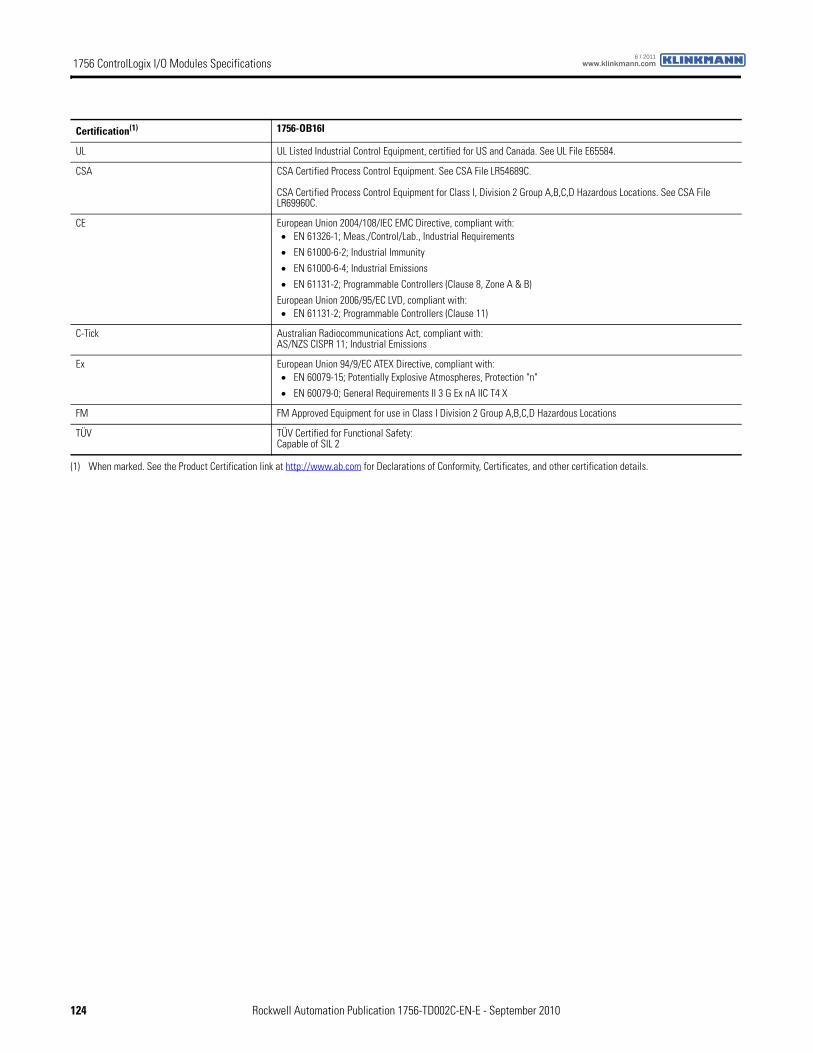
1756 ControlLogix I/O Modules Specifications www.klinkmann.com6 / 2011
Certification(1) 1756-OB16I
UL UL Listed Industrial Control Equipment, certified for US and Canada. See UL File E65584.
CSA CSA Certified Process Control Equipment. See CSA File LR54689C.
CSA Certified Process Control Equipment for Class I, Division 2 Group A,B,C,D Hazardous Locations. See CSA File LR69960C.
CE European Union 2004/108/IEC EMC Directive, compliant with:• EN 61326-1; Meas./Control/Lab., Industrial Requirements
• EN 61000-6-2; Industrial Immunity
• EN 61000-6-4; Industrial Emissions
• EN 61131-2; Programmable Controllers (Clause 8, Zone A & B)
European Union 2006/95/EC LVD, compliant with:• EN 61131-2; Programmable Controllers (Clause 11)
C-Tick Australian Radiocommunications Act, compliant with:AS/NZS CISPR 11; Industrial Emissions
Ex European Union 94/9/EC ATEX Directive, compliant with:• EN 60079-15; Potentially Explosive Atmospheres, Protection "n"
• EN 60079-0; General Requirements II 3 G Ex nA IIC T4 X
FM FM Approved Equipment for use in Class I Division 2 Group A,B,C,D Hazardous Locations
TÜV TÜV Certified for Functional Safety:Capable of SIL 2
(1) When marked. See the Product Certification link at http://www.ab.com for Declarations of Conformity, Certificates, and other certification details.
124 Rockwell Automation Publication 1756-TD002C-EN-E - September 2010
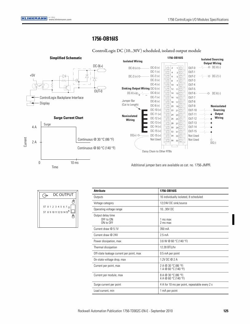
1756 ControlLogix I/O Modules Specificationswww.klinkmann.com6 / 2011
1756-OB16IS
ControlLogix DC (10...30V) scheduled, isolated output module
12
34
56
78
910
1112
1314
1516
1718
1920
2122
2324
2526
2728
2930
3132
3334
3536
+ –
Nonisolated Wiring
Isolated Wiring
Daisy Chain to Other RTBs
1756-OB16IS
DC-0 (+)DC-1 (+)DC-2 (+)DC-3 (+)
DC-8 (+)
DC-4 (+)DC-5 (+)DC-6 (+)DC-7 (+)
Not Used
DC-9 (+)DC-10 (+)DC-11 (+)DC-12 (+)DC-13 (+)DC-14 (+)DC-15 (+)DC-15 (+)
OUT-0OUT-1OUT-2OUT-3
OUT-8
OUT-4OUT-5OUT-6OUT-7
Not Used
OUT-9OUT-10OUT-11OUT-12OUT-13OUT-14OUT-15Not Used
DC-0 (+)
DC(+)
Jumper Bar (Cut to Length)
DC-2 (+)
DC-6 (+)
Sinking Output Wiring
NonisolatedSourcing
Output Wiring
Isolated Sourcing Output Wiring
DC-0 (-)
DC-2 (-)
DC-6 (-)
DC(-)
ControlLogix Backplane Interface
Continuous @ 60 °C (140 °F)
Display
Surge Current Chart
Simplified Schematic
Surge
Continuous @ 30 °C (86 °F)
OUT-0
DC-0(+)
Curre
nt
Time0 10 ms
2 A
4 A
+5V
Additional jumper bars are available as cat. no. 1756-JMPR.
Attribute 1756-OB16IS
Outputs 16 individually isolated, 8 scheduled
Voltage category 12/24V DC sink/source
Operating voltage range 10...30V DC
Output delay timeOFF to ONON to OFF
1 ms max 2 ms max
Current draw @ 5.1V 350 mA
Current draw @ 24V 2.5 mA
Power dissipation, max 3.6 W @ 60 °C (140 °F)
Thermal dissipation 12.28 BTU/hr
Off-state leakage current per point, max 0.5 mA per point
On-state voltage drop, max 1.2V DC @ 2 A
Current per point, max 2 A @ 30 °C (86 °F)1 A @ 60 °C (140 °F)
Current per module, max 8 A @ 30 °C (86 °F)4 A @ 60 °C (140 °F)
Surge current per point 4 A for 10 ms per point, repeatable every 2 s
Load current, min 1 mA per point
DC OUTPUT
ST 0 1 2 3 4 5 6 7
ST 8 9 10 11 12 13 14 15
OK
Rockwell Automation Publication 1756-TD002C-EN-E - September 2010 125

1756 ControlLogix I/O Modules Specifications www.klinkmann.com6 / 2011
Isolation voltage 250V (continuous), basic insulation type, outputs-to-backplane, and output-to-output
Routine tested @ 1350V AC for 2 s
Removable terminal block 1756-TBCH1756-TBS6H
Slot width 1
Wire size 0.33... 2.1 mm2 (22...14 AWG) solid or stranded copper wire rated at 90 °C (194 °F), or greater, 1.2 mm (3/64 in.) insulation max(1)
Wire category 1(2)
Wire type Copper
North American temperature code T4A
IEC temperature code T4
Enclosure type None (open-style)
(1) Maximum wire size requires extended housing, catalog number 1756-TBE.
(2) Use this conductor category information for planning conductor routing as described in the system-level installation manual. See the Industrial Automation Wiring and Grounding Guidelines, publication 1770-4.1.
Attribute 1756-OB16IS
Attribute 1756-OB16IS
Temperature, operatingIEC 60068-2-1 (Test Ad, Operating Cold),IEC 60068-2-2 (Test Bd, Operating Dry Heat),IEC 60068-2-14 (Test Nb, Operating Thermal Shock)
0…60 °C (32…140 °F)
Temperature, surrounding air 60 °C (140 °F)
Temperature, storageIEC 60068-2-1 (Test Ab, Unpackaged Nonoperating Cold),IEC 60068-2-2 (Test Bb, Unpackaged Nonoperating Dry Heat),IEC 60068-2-14 (Test Na, Unpackaged Nonoperating Thermal Shock)
-40…85 °C (-40…185 °F)
Relative humidityIEC 60068-2-30 (Test Db, Unpackaged Nonoperating Damp Heat)
5…95% noncondensing
VibrationIEC 60068-2-6 (Test Fc, Operating)
2 g @ 10…500 Hz
Shock, operatingIEC 60068-2-27 (Test Ea, Unpackaged Shock)
30 g
Shock, nonoperatingIEC 60068-2-27 (Test Ea, Unpackaged Shock)
50 g
Emissions CISPR 11: Group 1, Class A
ESD immunityIEC 61000-4-2
6 kV contact discharges8 kV air discharges
Radiated RF immunityIEC 61000-4-3
10V/m with 1 kHz sine-wave 80% AM from 80... 2000 MHz10V/m with 200 Hz 50% Pulse 100% AM @ 900 MHz10V/m with 200 Hz 50% Pulse 100% AM @ 1890 MHz3V/m with 1 kHz sine-wave 80% AM from 2000...2700 MHz
EFT/B immunityIEC 61000-4-4
±4 kV at 5 kHz on signal ports
Surge transient immunityIEC 61000-4-5
±1 kV line-line (DM) and ±2 kV line-earth (CM) on signal ports
Conducted RF immunityIEC 61000-4-6
10Vrms with 1 kHz sine-wave 80% AM from 150 kHz...80 MHz
126 Rockwell Automation Publication 1756-TD002C-EN-E - September 2010
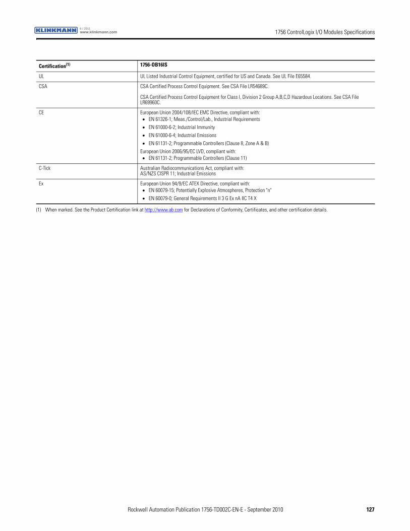
1756 ControlLogix I/O Modules Specificationswww.klinkmann.com6 / 2011
Certification(1) 1756-OB16IS
UL UL Listed Industrial Control Equipment, certified for US and Canada. See UL File E65584.
CSA CSA Certified Process Control Equipment. See CSA File LR54689C.
CSA Certified Process Control Equipment for Class I, Division 2 Group A,B,C,D Hazardous Locations. See CSA File LR69960C.
CE European Union 2004/108/IEC EMC Directive, compliant with:• EN 61326-1; Meas./Control/Lab., Industrial Requirements
• EN 61000-6-2; Industrial Immunity
• EN 61000-6-4; Industrial Emissions
• EN 61131-2; Programmable Controllers (Clause 8, Zone A & B)
European Union 2006/95/EC LVD, compliant with:• EN 61131-2; Programmable Controllers (Clause 11)
C-Tick Australian Radiocommunications Act, compliant with:AS/NZS CISPR 11; Industrial Emissions
Ex European Union 94/9/EC ATEX Directive, compliant with:• EN 60079-15; Potentially Explosive Atmospheres, Protection "n"
• EN 60079-0; General Requirements II 3 G Ex nA IIC T4 X
(1) When marked. See the Product Certification link at http://www.ab.com for Declarations of Conformity, Certificates, and other certification details.
Rockwell Automation Publication 1756-TD002C-EN-E - September 2010 127
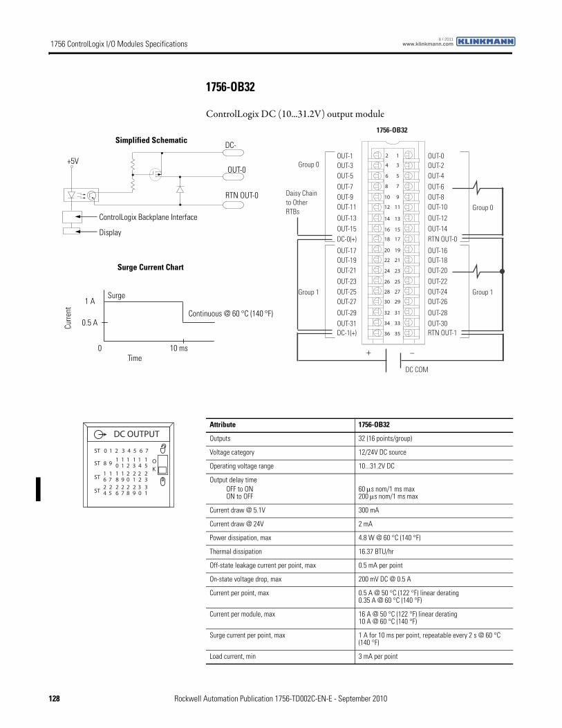
1756 ControlLogix I/O Modules Specifications www.klinkmann.com6 / 2011
1756-OB32
ControlLogix DC (10...31.2V) output module
12
34
56
78
910
1112
1314
1516
1718
1920
2122
2324
2526
2728
2930
3132
3334
3536
+ _
Daisy Chain to Other RTBs
Group 0
Group 1
Group 0
Group 1
DC COM
OUT-1OUT-3OUT-5OUT-7OUT-9OUT-11
OUT-13OUT-15DC-0(+)
DC-1(+)
OUT-0OUT-2OUT-4OUT-6OUT-8OUT-10
OUT-12OUT-14RTN OUT-0
RTN OUT-1
OUT-17OUT-19OUT-21OUT-23OUT-25OUT-27
OUT-29OUT-31
OUT-16OUT-18OUT-20OUT-22OUT-24OUT-26
OUT-28OUT-30
1756-OB32
Continuous @ 60 °C (140 °F)
+5V
RTN OUT-0
OUT-0
DC-
ControlLogix Backplane Interface
Display
Surge Current Chart
Simplified Schematic
Surge
Curre
nt
Time0 10 ms
0.5 A
1 A
Attribute 1756-OB32
Outputs 32 (16 points/group)
Voltage category 12/24V DC source
Operating voltage range 10...31.2V DC
Output delay timeOFF to ONON to OFF
60 μs nom/1 ms max 200 μs nom/1 ms max
Current draw @ 5.1V 300 mA
Current draw @ 24V 2 mA
Power dissipation, max 4.8 W @ 60 °C (140 °F)
Thermal dissipation 16.37 BTU/hr
Off-state leakage current per point, max 0.5 mA per point
On-state voltage drop, max 200 mV DC @ 0.5 A
Current per point, max 0.5 A @ 50 °C (122 °F) linear derating0.35 A @ 60 °C (140 °F)
Current per module, max 16 A @ 50 °C (122 °F) linear derating10 A @ 60 °C (140 °F)
Surge current per point, max 1 A for 10 ms per point, repeatable every 2 s @ 60 °C (140 °F)
Load current, min 3 mA per point
DC OUTPUT
OK
ST 0 1 2 3 4 5 6 7
ST 8 910 21 3 4 5
1 1 1 11
ST 6 718 09 1 2 3
1 2 2 221 1
ST 4 526 87 9 0 1
2 2 2 332 2
128 Rockwell Automation Publication 1756-TD002C-EN-E - September 2010
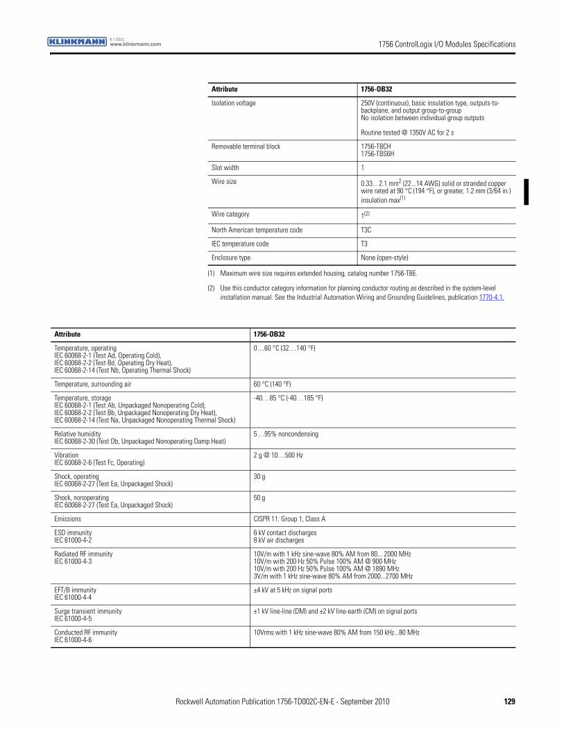
1756 ControlLogix I/O Modules Specificationswww.klinkmann.com6 / 2011
Isolation voltage 250V (continuous), basic insulation type, outputs-to-backplane, and output group-to-groupNo isolation between individual group outputs
Routine tested @ 1350V AC for 2 s
Removable terminal block 1756-TBCH1756-TBS6H
Slot width 1
Wire size 0.33... 2.1 mm2 (22...14 AWG) solid or stranded copper wire rated at 90 °C (194 °F), or greater, 1.2 mm (3/64 in.) insulation max(1)
Wire category 1(2)
North American temperature code T3C
IEC temperature code T3
Enclosure type None (open-style)
(1) Maximum wire size requires extended housing, catalog number 1756-TBE.
(2) Use this conductor category information for planning conductor routing as described in the system-level installation manual. See the Industrial Automation Wiring and Grounding Guidelines, publication 1770-4.1.
Attribute 1756-OB32
Attribute 1756-OB32
Temperature, operatingIEC 60068-2-1 (Test Ad, Operating Cold),IEC 60068-2-2 (Test Bd, Operating Dry Heat),IEC 60068-2-14 (Test Nb, Operating Thermal Shock)
0…60 °C (32…140 °F)
Temperature, surrounding air 60 °C (140 °F)
Temperature, storageIEC 60068-2-1 (Test Ab, Unpackaged Nonoperating Cold),IEC 60068-2-2 (Test Bb, Unpackaged Nonoperating Dry Heat),IEC 60068-2-14 (Test Na, Unpackaged Nonoperating Thermal Shock)
-40…85 °C (-40…185 °F)
Relative humidityIEC 60068-2-30 (Test Db, Unpackaged Nonoperating Damp Heat)
5…95% noncondensing
VibrationIEC 60068-2-6 (Test Fc, Operating)
2 g @ 10…500 Hz
Shock, operatingIEC 60068-2-27 (Test Ea, Unpackaged Shock)
30 g
Shock, nonoperatingIEC 60068-2-27 (Test Ea, Unpackaged Shock)
50 g
Emissions CISPR 11: Group 1, Class A
ESD immunityIEC 61000-4-2
6 kV contact discharges8 kV air discharges
Radiated RF immunityIEC 61000-4-3
10V/m with 1 kHz sine-wave 80% AM from 80... 2000 MHz10V/m with 200 Hz 50% Pulse 100% AM @ 900 MHz10V/m with 200 Hz 50% Pulse 100% AM @ 1890 MHz3V/m with 1 kHz sine-wave 80% AM from 2000...2700 MHz
EFT/B immunityIEC 61000-4-4
±4 kV at 5 kHz on signal ports
Surge transient immunityIEC 61000-4-5
±1 kV line-line (DM) and ±2 kV line-earth (CM) on signal ports
Conducted RF immunityIEC 61000-4-6
10Vrms with 1 kHz sine-wave 80% AM from 150 kHz...80 MHz
Rockwell Automation Publication 1756-TD002C-EN-E - September 2010 129
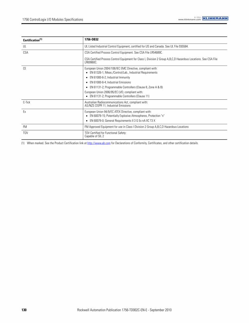
1756 ControlLogix I/O Modules Specifications www.klinkmann.com6 / 2011
Certification(1) 1756-OB32
UL UL Listed Industrial Control Equipment, certified for US and Canada. See UL File E65584.
CSA CSA Certified Process Control Equipment. See CSA File LR54689C.
CSA Certified Process Control Equipment for Class I, Division 2 Group A,B,C,D Hazardous Locations. See CSA File LR69960C.
CE European Union 2004/108/IEC EMC Directive, compliant with:• EN 61326-1; Meas./Control/Lab., Industrial Requirements
• EN 61000-6-2; Industrial Immunity
• EN 61000-6-4; Industrial Emissions
• EN 61131-2; Programmable Controllers (Clause 8, Zone A & B)
European Union 2006/95/EC LVD, compliant with:• EN 61131-2; Programmable Controllers (Clause 11)
C-Tick Australian Radiocommunications Act, compliant with:AS/NZS CISPR 11; Industrial Emissions
Ex European Union 94/9/EC ATEX Directive, compliant with:• EN 60079-15; Potentially Explosive Atmospheres, Protection "n"
• EN 60079-0; General Requirements II 3 G Ex nA IIC T3 X
FM FM Approved Equipment for use in Class I Division 2 Group A,B,C,D Hazardous Locations
TÜV TÜV Certified for Functional Safety:Capable of SIL 2
(1) When marked. See the Product Certification link at http://www.ab.com for Declarations of Conformity, Certificates, and other certification details.
130 Rockwell Automation Publication 1756-TD002C-EN-E - September 2010
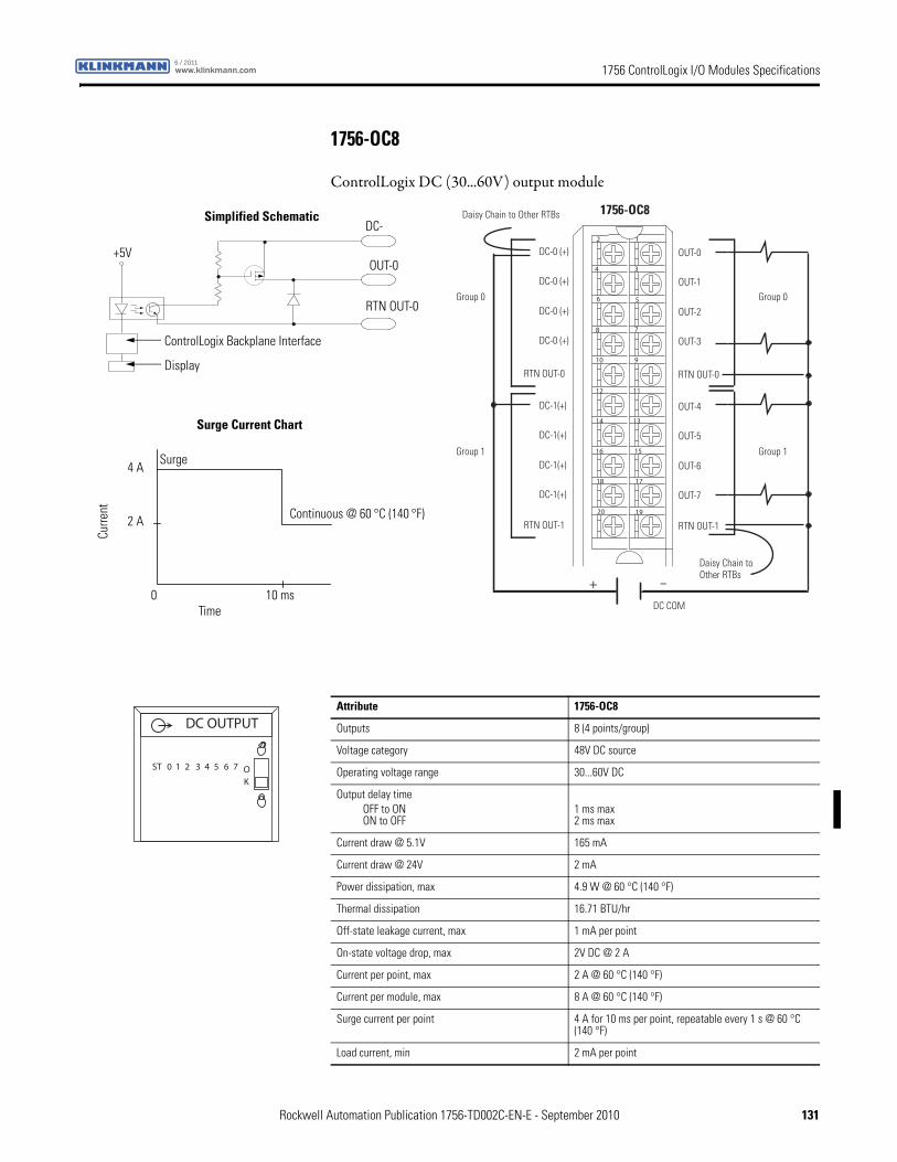
1756 ControlLogix I/O Modules Specificationswww.klinkmann.com6 / 2011
1756-OC8
ControlLogix DC (30...60V) output module
12
34
56
78
910
1112
1314
1516
1718
1920
+ –
Group 0
Group 1
Daisy Chain to Other RTBs
Daisy Chain to Other RTBs
1756-OC8
Group 0
Group 1
DC-0 (+)
DC-0 (+)
DC-0 (+)
DC-0 (+)
DC-1(+)
DC-1(+)
DC-1(+)
DC-1(+)
RTN OUT-0
RTN OUT-1
OUT-0
OUT-1
OUT-2
OUT-3
OUT-4
OUT-5
OUT-6
OUT-7
RTN OUT-0
RTN OUT-1
DC COM
Continuous @ 60 °C (140 °F)
+5V
RTN OUT-0
OUT-0
DC-
ControlLogix Backplane Interface
Display
Surge Current Chart
Simplified Schematic
Surge
Curre
nt
Time0 10 ms
2 A
4 A
Attribute 1756-OC8
Outputs 8 (4 points/group)
Voltage category 48V DC source
Operating voltage range 30...60V DC
Output delay timeOFF to ONON to OFF
1 ms max 2 ms max
Current draw @ 5.1V 165 mA
Current draw @ 24V 2 mA
Power dissipation, max 4.9 W @ 60 °C (140 °F)
Thermal dissipation 16.71 BTU/hr
Off-state leakage current, max 1 mA per point
On-state voltage drop, max 2V DC @ 2 A
Current per point, max 2 A @ 60 °C (140 °F)
Current per module, max 8 A @ 60 °C (140 °F)
Surge current per point 4 A for 10 ms per point, repeatable every 1 s @ 60 °C (140 °F)
Load current, min 2 mA per point
DC OUTPUT
ST 0 1 2 3 4 5 6 7 OK
Rockwell Automation Publication 1756-TD002C-EN-E - September 2010 131
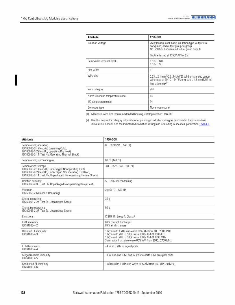
1756 ControlLogix I/O Modules Specifications www.klinkmann.com6 / 2011
Isolation voltage 250V (continuous), basic insulation type, outputs-to-backplane, and output group-to-groupNo isolation between individual group outputs
Routine tested at 1350V AC for 2 s
Removable terminal block 1756-TBNH1756-TBSH
Slot width 1
Wire size 0.33... 2.1 mm2 (22...14 AWG) solid or stranded copper wire rated at 90 °C (194 °F), or greater, 1.2 mm (3/64 in.) insulation max(1)
Wire category 1(2)
North American temperature code T4
IEC temperature code T4
Enclosure type None (open-style)
(1) Maximum wire size requires extended housing, catalog number 1756-TBE.
(2) Use this conductor category information for planning conductor routing as described in the system-level installation manual. See the Industrial Automation Wiring and Grounding Guidelines, publication 1770-4.1.
Attribute 1756-OC8
Attribute 1756-OC8
Temperature, operatingIEC 60068-2-1 (Test Ad, Operating Cold),IEC 60068-2-2 (Test Bd, Operating Dry Heat),IEC 60068-2-14 (Test Nb, Operating Thermal Shock)
0…60 °C (32…140 °F)
Temperature, surrounding air 60 °C (140 °F)
Temperature, storageIEC 60068-2-1 (Test Ab, Unpackaged Nonoperating Cold),IEC 60068-2-2 (Test Bb, Unpackaged Nonoperating Dry Heat),IEC 60068-2-14 (Test Na, Unpackaged Nonoperating Thermal Shock)
-40…85 °C (-40…185 °F)
Relative humidityIEC 60068-2-30 (Test Db, Unpackaged Nonoperating Damp Heat)
5…95% noncondensing
VibrationIEC 60068-2-6 (Test Fc, Operating)
2 g @ 10…500 Hz
Shock, operatingIEC 60068-2-27 (Test Ea, Unpackaged Shock)
30 g
Shock, nonoperatingIEC 60068-2-27 (Test Ea, Unpackaged Shock)
50 g
Emissions CISPR 11: Group 1, Class A
ESD immunityIEC 61000-4-2
6 kV contact discharges8 kV air discharges
Radiated RF immunityIEC 61000-4-3
10V/m with 1 kHz sine-wave 80% AM from 80... 2000 MHz10V/m with 200 Hz 50% Pulse 100% AM @ 900 MHz10V/m with 200 Hz 50% Pulse 100% AM @ 1890 MHz3V/m with 1 kHz sine-wave 80% AM from 2000...2700 MHz
EFT/B immunityIEC 61000-4-4
±4 kV at 5 kHz on signal ports
Surge transient immunityIEC 61000-4-5
±1 kV line-line (DM) and ±2 kV line-earth (CM) on signal ports
Conducted RF immunityIEC 61000-4-6
10Vrms with 1 kHz sine-wave 80% AM from 150 kHz...80 MHz
132 Rockwell Automation Publication 1756-TD002C-EN-E - September 2010
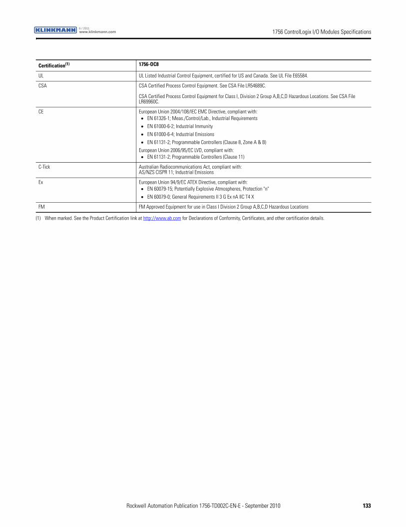
1756 ControlLogix I/O Modules Specificationswww.klinkmann.com6 / 2011
Certification(1) 1756-OC8
UL UL Listed Industrial Control Equipment, certified for US and Canada. See UL File E65584.
CSA CSA Certified Process Control Equipment. See CSA File LR54689C.
CSA Certified Process Control Equipment for Class I, Division 2 Group A,B,C,D Hazardous Locations. See CSA File LR69960C.
CE European Union 2004/108/IEC EMC Directive, compliant with:• EN 61326-1; Meas./Control/Lab., Industrial Requirements
• EN 61000-6-2; Industrial Immunity
• EN 61000-6-4; Industrial Emissions
• EN 61131-2; Programmable Controllers (Clause 8, Zone A & B)
European Union 2006/95/EC LVD, compliant with:• EN 61131-2; Programmable Controllers (Clause 11)
C-Tick Australian Radiocommunications Act, compliant with:AS/NZS CISPR 11; Industrial Emissions
Ex European Union 94/9/EC ATEX Directive, compliant with:• EN 60079-15; Potentially Explosive Atmospheres, Protection "n"
• EN 60079-0; General Requirements II 3 G Ex nA IIC T4 X
FM FM Approved Equipment for use in Class I Division 2 Group A,B,C,D Hazardous Locations
(1) When marked. See the Product Certification link at http://www.ab.com for Declarations of Conformity, Certificates, and other certification details.
Rockwell Automation Publication 1756-TD002C-EN-E - September 2010 133
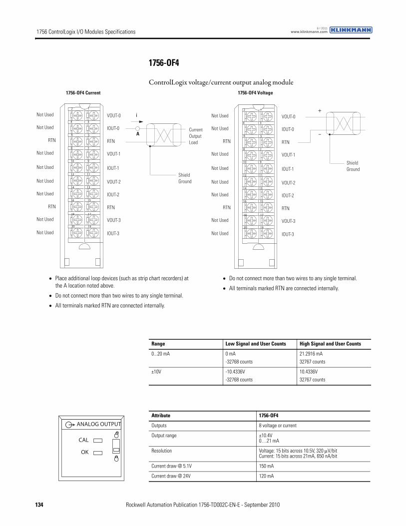
1756 ControlLogix I/O Modules Specifications www.klinkmann.com6 / 2011
1756-OF4
ControlLogix voltage/current output analog module
12
34
56
78
910
1112
1314
1516
1718
1920
i
Current Output Load
Shield Ground
1756-OF4 Current
Not Used
Not Used
RTN
Not Used
Not Used
Not Used
RTN
Not Used
Not Used
Not Used
VOUT-0
IOUT-0
RTN
VOUT-1
VOUT-2
IOUT-2
RTN
VOUT-3
IOUT-1
IOUT-3
A
12
34
56
78
910
1112
1314
1516
1718
1920
+
–
Shield Ground
1756-OF4 Voltage
Not Used
Not Used
RTN
Not Used
Not Used
Not Used
RTN
Not Used
Not Used
Not Used
VOUT-0
IOUT-0
RTN
VOUT-1
VOUT-2
IOUT-2
RTN
VOUT-3
IOUT-1
IOUT-3
• Place additional loop devices (such as strip chart recorders) at the A location noted above.
• Do not connect more than two wires to any single terminal.
• All terminals marked RTN are connected internally.
• Do not connect more than two wires to any single terminal.
• All terminals marked RTN are connected internally.
Range Low Signal and User Counts High Signal and User Counts
0...20 mA 0 mA
-32768 counts
21.2916 mA
32767 counts
±10V -10.4336V
-32768 counts
10.4336V
32767 counts
Attribute 1756-OF4
Outputs 8 voltage or current
Output range ±10.4V0…21 mA
Resolution Voltage: 15 bits across 10.5V, 320 μV/bitCurrent: 15 bits across 21mA, 650 nA/bit
Current draw @ 5.1V 150 mA
Current draw @ 24V 120 mA
ANALOG OUTPUT
CAL
OK
134 Rockwell Automation Publication 1756-TD002C-EN-E - September 2010
1756 ControlLogix I/O Modules Specificationswww.klinkmann.com6 / 2011
Power dissipation, max 3.25 W, 4 channel current
Thermal dissipation 10.91 BTU/hr
Open circuit detection Current output only (Output must be set to >0.1 mA)
Overvoltage protection 24V DC
Short circuit protection Electronically current limited to 21mA or less
Drive capability Voltage: >2000 ΩCurrent: 0…750 Ω
Settling time <2 ms to 95% of final value with resistive loads
Calibrated accuracy Better than 0.05% of range from 4…21 mA, -10.4…10.4V
Calibration interval 12 months typical
Offset drift 50 μV/ °C100 nA/°C
Gain drift with temperature Voltage: 25 ppm/°C, 520 μV/°CCurrent: 50 ppm/°C, 1050 μA/°C
Module error Voltage: 0.15% of rangeCurrent: 0.3% of range
Module scan time 12 ms floating point8 ms integer
Isolation voltage 250V (continuous), reinforced insulation type, output channels-to-backplaneNo isolation between individual output channels
Routine tested at 1350V AC for 2 s
Removable terminal block 1756-TBNH1756-TBSH
Slot width 1
Wire size 0.33... 2.1 mm2 (22...14 AWG) solid or stranded copper wire rated at 90 °C (194 °F), or greater, 1.2 mm (3/64 in.) insulation max(1)
Wire category 2(2)
North American temperature code T4A
IEC temperature code T4
Enclosure type None (open-style)
(1) Maximum wire size requires extended housing, catalog number 1756-TBE.
(2) Use this conductor category information for planning conductor routing as described in the system-level installation manual. See the Industrial Automation Wiring and Grounding Guidelines, publication 1770-4.1.
Attribute 1756-OF4
Attribute 1756-OF4
Temperature, operatingIEC 60068-2-1 (Test Ad, Operating Cold),IEC 60068-2-2 (Test Bd, Operating Dry Heat),IEC 60068-2-14 (Test Nb, Operating Thermal Shock)
0…60 °C (32…140 °F)
Temperature, surrounding air 60 °C (140 °F)
Temperature, storageIEC 60068-2-1 (Test Ab, Unpackaged Nonoperating Cold),IEC 60068-2-2 (Test Bb, Unpackaged Nonoperating Dry Heat),IEC 60068-2-14 (Test Na, Unpackaged Nonoperating Thermal Shock)
-40…85 °C (-40…185 °F)
Relative humidityIEC 60068-2-30 (Test Db, Unpackaged Nonoperating Damp Heat)
5…95% noncondensing
Rockwell Automation Publication 1756-TD002C-EN-E - September 2010 135
1756 ControlLogix I/O Modules Specifications www.klinkmann.com6 / 2011
VibrationIEC 60068-2-6 (Test Fc, Operating)
2 g @ 10…500 Hz
Shock, operatingIEC 60068-2-27 (Test Ea, Unpackaged Shock)
30 g
Shock, nonoperatingIEC 60068-2-27 (Test Ea, Unpackaged Shock)
50 g
Emissions CISPR 11: Group 1, Class A
ESD immunityIEC 61000-4-2
6 kV contact discharges8 kV air discharges
Radiated RF immunityIEC 61000-4-3
10V/m with 1 kHz sine-wave 80% AM from 80... 2000 MHz10V/m with 200 Hz 50% Pulse 100% AM @ 900 MHz10V/m with 200 Hz 50% Pulse 100% AM @ 1890 MHz3V/m with 1 kHz sine-wave 80% AM from 2000...2700 MHz
EFT/B immunityIEC 61000-4-4
±2 kV at 5 kHz on shielded signal ports
Surge transient immunityIEC 61000-4-5
±2 kV line-earth (CM) on shielded signal ports
Conducted RF immunityIEC 61000-4-6
10Vrms with 1 kHz sine-wave 80% AM from 150 kHz...80 MHz on shielded signal ports
Attribute 1756-OF4
Certification(1) 1756-OF4
UL UL Listed Industrial Control Equipment, certified for US and Canada. See UL File E65584.
CSA CSA Certified Process Control Equipment. See CSA File LR54689C.
CSA Certified Process Control Equipment for Class I, Division 2 Group A,B,C,D Hazardous Locations. See CSA File LR69960C.
CE European Union 2004/108/IEC EMC Directive, compliant with:• EN 61326-1; Meas./Control/Lab., Industrial Requirements
• EN 61000-6-2; Industrial Immunity
• EN 61000-6-4; Industrial Emissions
• EN 61131-2; Programmable Controllers (Clause 8, Zone A & B)
European Union 2006/95/EC LVD, compliant with:• EN 61131-2; Programmable Controllers (Clause 11)
C-Tick Australian Radiocommunications Act, compliant with:AS/NZS CISPR 11; Industrial Emissions
Ex European Union 94/9/EC ATEX Directive, compliant with:• EN 60079-15; Potentially Explosive Atmospheres, Protection "n"
• EN 60079-0; General Requirements II 3 G Ex nA IIC T4 X
FM FM Approved Equipment for use in Class I Division 2 Group A,B,C,D Hazardous Locations
(1) When marked. See the Product Certification link at http://www.ab.com for Declarations of Conformity, Certificates, and other certification details.
136 Rockwell Automation Publication 1756-TD002C-EN-E - September 2010
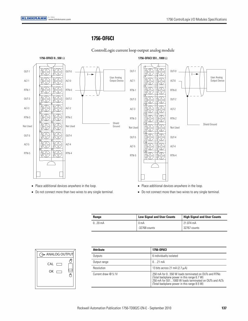
1756 ControlLogix I/O Modules Specificationswww.klinkmann.com6 / 2011
1756-OF6CI
ControlLogix current loop output analog module
12
34
56
78
910
1112
1314
1516
1718
1920
iOUT-1
ALT-1
RTN-1
OUT-3
RTN-3
Not Used
OUT-5
ALT-5
ALT-3
RTN-5
OUT-0
ALT-0
RTN-0
OUT-2
RTN-2
Not Used
OUT-4
ALT-4
ALT-2
RTN-4
User Analog Output Device
Shield Ground
1756-OF6CI 0...550 Ω
12
34
56
78
910
1112
1314
1516
1718
1920
iOUT-1
ALT-1
RTN-1
OUT-3
RTN-3
Not Used
OUT-5
ALT-5
ALT-3
RTN-5
OUT-0
ALT-0
RTN-0
OUT-2
RTN-2
Not Used
OUT-4
ALT-4
ALT-2
RTN-4
User Analog Output Device
Shield Ground
1756-OF6CI 551...1000 Ω
• Place additional devices anywhere in the loop.
• Do not connect more than two wires to any single terminal.
• Place additional devices anywhere in the loop.
• Do not connect more than two wires to any single terminal.
Range Low Signal and User Counts High Signal and User Counts
0...20 mA 0 mA
-32768 counts
21.074 mA
32767 counts
Attribute 1756-OF6CI
Outputs 6 individually isolated
Output range 0…21 mA
Resolution 13 bits across 21 mA (2.7 μA)
Current draw @ 5.1V 250 mA for 0...550 W loads terminated on OUTs and RTNs(Total backplane power in this range 6.7 W)250 mA for 551...1000 W loads terminated on OUTs and ALTs(Total backplane power in this range 8.5 W)
ANALOG OUTPUT
CAL
OK
Rockwell Automation Publication 1756-TD002C-EN-E - September 2010 137
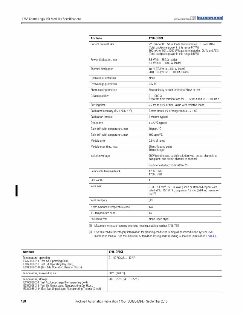
1756 ControlLogix I/O Modules Specifications www.klinkmann.com6 / 2011
Current draw @ 24V 225 mA for 0...550 W loads terminated on OUTs and RTNs(Total backplane power in this range 6.7 W)300 mA for 551...1000 W loads terminated on OUTs and ALTs(Total backplane power in this range 8.5 W)
Power dissipation, max 5.5 W (0…550 Ω loads)6.1 W (551…1000 Ω loads)
Thermal dissipation 18.76 BTU/hr (0…550 Ω loads)20.80 BTU/hr (551…1000 Ω loads)
Open circuit detection None
Overvoltage protection 24V DC
Short circuit protection Electronically current limited to 21mA or less
Drive capability 0…1000 ΩSeparate field terminations for 0…550 Ω and 551…1000 Ω
Settling time < 2 ms to 95% of final value with resistive loads
Calibrated accuracy @ 25 °C (77 °F) Better than 0.1% of range from 4…21 mA
Calibration interval 6 months typical
Offset drift 1 μA/°C typical
Gain drift with temperature, nom 60 ppm/°C
Gain drift with temperature, max 100 ppm/°C
Module error 0.6% of range
Module scan time, max 25 ms floating point10 ms integer
Isolation voltage 250V (continuous), basic insulation type, output channels-to-backplane, and output channel-to-channel
Routine tested at 1350V AC for 2 s
Removable terminal block 1756-TBNH1756-TBSH
Slot width 1
Wire size 0.33... 2.1 mm2 (22...14 AWG) solid or stranded copper wire rated at 90 °C (194 °F), or greater, 1.2 mm (3/64 in.) insulation max(1)
Wire category 2(2)
North American temperature code T4A
IEC temperature code T4
Enclosure type None (open-style)
(1) Maximum wire size requires extended housing, catalog number 1756-TBE.
(2) Use this conductor category information for planning conductor routing as described in the system-level installation manual. See the Industrial Automation Wiring and Grounding Guidelines, publication 1770-4.1.
Attribute 1756-OF6CI
Attribute 1756-OF6CI
Temperature, operatingIEC 60068-2-1 (Test Ad, Operating Cold),IEC 60068-2-2 (Test Bd, Operating Dry Heat),IEC 60068-2-14 (Test Nb, Operating Thermal Shock)
0…60 °C (32…140 °F)
Temperature, surrounding air 60 °C (140 °F)
Temperature, storageIEC 60068-2-1 (Test Ab, Unpackaged Nonoperating Cold),IEC 60068-2-2 (Test Bb, Unpackaged Nonoperating Dry Heat),IEC 60068-2-14 (Test Na, Unpackaged Nonoperating Thermal Shock)
-40…85 °C (-40…185 °F)
138 Rockwell Automation Publication 1756-TD002C-EN-E - September 2010
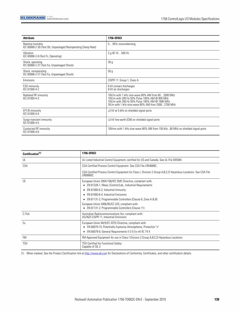
1756 ControlLogix I/O Modules Specificationswww.klinkmann.com6 / 2011
Relative humidityIEC 60068-2-30 (Test Db, Unpackaged Nonoperating Damp Heat)
5…95% noncondensing
VibrationIEC 60068-2-6 (Test Fc, Operating)
2 g @ 10…500 Hz
Shock, operatingIEC 60068-2-27 (Test Ea, Unpackaged Shock)
30 g
Shock, nonoperatingIEC 60068-2-27 (Test Ea, Unpackaged Shock)
50 g
Emissions CISPR 11: Group 1, Class A
ESD immunityIEC 61000-4-2
6 kV contact discharges8 kV air discharges
Radiated RF immunityIEC 61000-4-3
10V/m with 1 kHz sine-wave 80% AM from 80... 2000 MHz10V/m with 200 Hz 50% Pulse 100% AM @ 900 MHz10V/m with 200 Hz 50% Pulse 100% AM @ 1890 MHz3V/m with 1 kHz sine-wave 80% AM from 2000...2700 MHz
EFT/B immunityIEC 61000-4-4
±2 kV at 5 kHz on shielded signal ports
Surge transient immunityIEC 61000-4-5
±2 kV line-earth (CM) on shielded signal ports
Conducted RF immunityIEC 61000-4-6
10Vrms with 1 kHz sine-wave 80% AM from 150 kHz...80 MHz on shielded signal ports
Attribute 1756-OF6CI
Certification(1) 1756-OF6CI
UL UL Listed Industrial Control Equipment, certified for US and Canada. See UL File E65584.
CSA CSA Certified Process Control Equipment. See CSA File LR54689C.
CSA Certified Process Control Equipment for Class I, Division 2 Group A,B,C,D Hazardous Locations. See CSA File LR69960C.
CE European Union 2004/108/IEC EMC Directive, compliant with:• EN 61326-1; Meas./Control/Lab., Industrial Requirements
• EN 61000-6-2; Industrial Immunity
• EN 61000-6-4; Industrial Emissions
• EN 61131-2; Programmable Controllers (Clause 8, Zone A & B)
European Union 2006/95/EC LVD, compliant with:• EN 61131-2; Programmable Controllers (Clause 11)
C-Tick Australian Radiocommunications Act, compliant with:AS/NZS CISPR 11; Industrial Emissions
Ex European Union 94/9/EC ATEX Directive, compliant with:• EN 60079-15; Potentially Explosive Atmospheres, Protection "n"
• EN 60079-0; General Requirements II 3 G Ex nA IIC T4 X
FM FM Approved Equipment for use in Class I Division 2 Group A,B,C,D Hazardous Locations
TÜV TÜV Certified for Functional Safety:Capable of SIL 2
(1) When marked. See the Product Certification link at http://www.ab.com for Declarations of Conformity, Certificates, and other certification details.
Rockwell Automation Publication 1756-TD002C-EN-E - September 2010 139
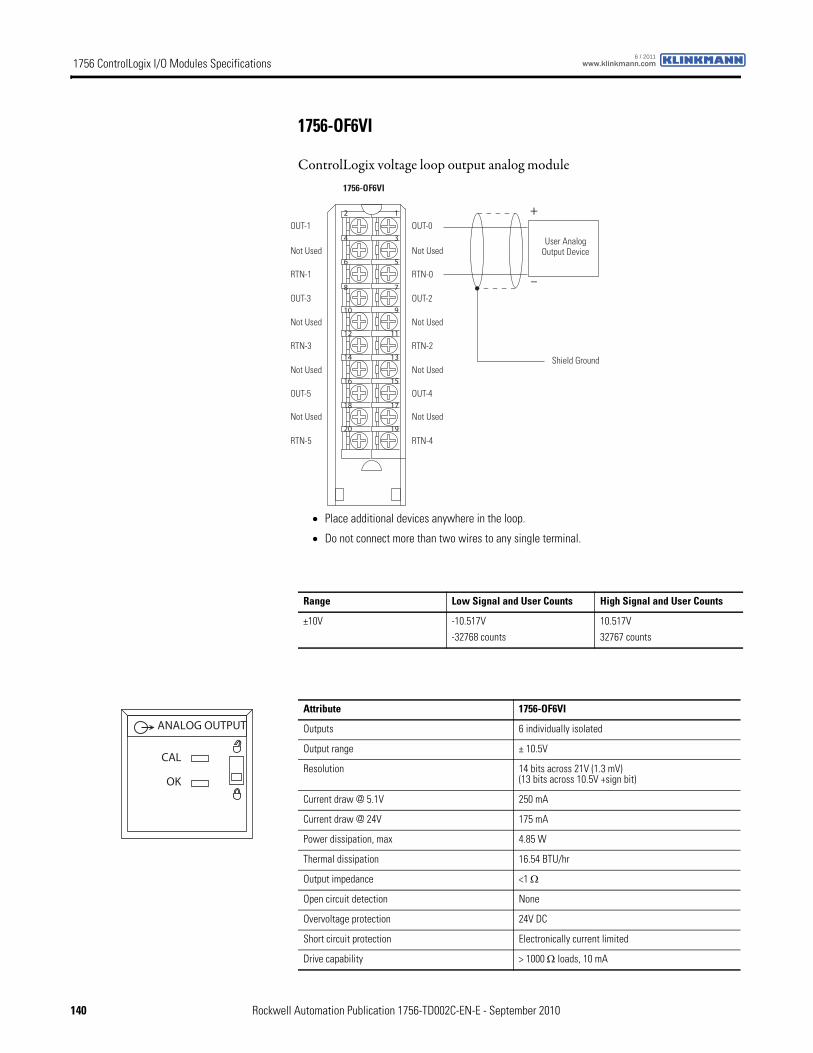
1756 ControlLogix I/O Modules Specifications www.klinkmann.com6 / 2011
1756-OF6VI
ControlLogix voltage loop output analog module
12
34
56
78
910
1112
1314
1516
1718
1920
+
–
Shield Ground
1756-OF6VI
OUT-1
Not Used
RTN-1
OUT-3
RTN-3
Not Used
OUT-5
Not Used
Not Used
RTN-5
OUT-0
Not Used
RTN-0
OUT-2
RTN-2
Not Used
OUT-4
Not Used
Not Used
RTN-4
User Analog Output Device
• Place additional devices anywhere in the loop.
• Do not connect more than two wires to any single terminal.
Range Low Signal and User Counts High Signal and User Counts
±10V -10.517V
-32768 counts
10.517V
32767 counts
Attribute 1756-OF6VI
Outputs 6 individually isolated
Output range ± 10.5V
Resolution 14 bits across 21V (1.3 mV)(13 bits across 10.5V +sign bit)
Current draw @ 5.1V 250 mA
Current draw @ 24V 175 mA
Power dissipation, max 4.85 W
Thermal dissipation 16.54 BTU/hr
Output impedance <1 Ω
Open circuit detection None
Overvoltage protection 24V DC
Short circuit protection Electronically current limited
Drive capability > 1000 Ω loads, 10 mA
ANALOG OUTPUT
CAL
OK
140 Rockwell Automation Publication 1756-TD002C-EN-E - September 2010
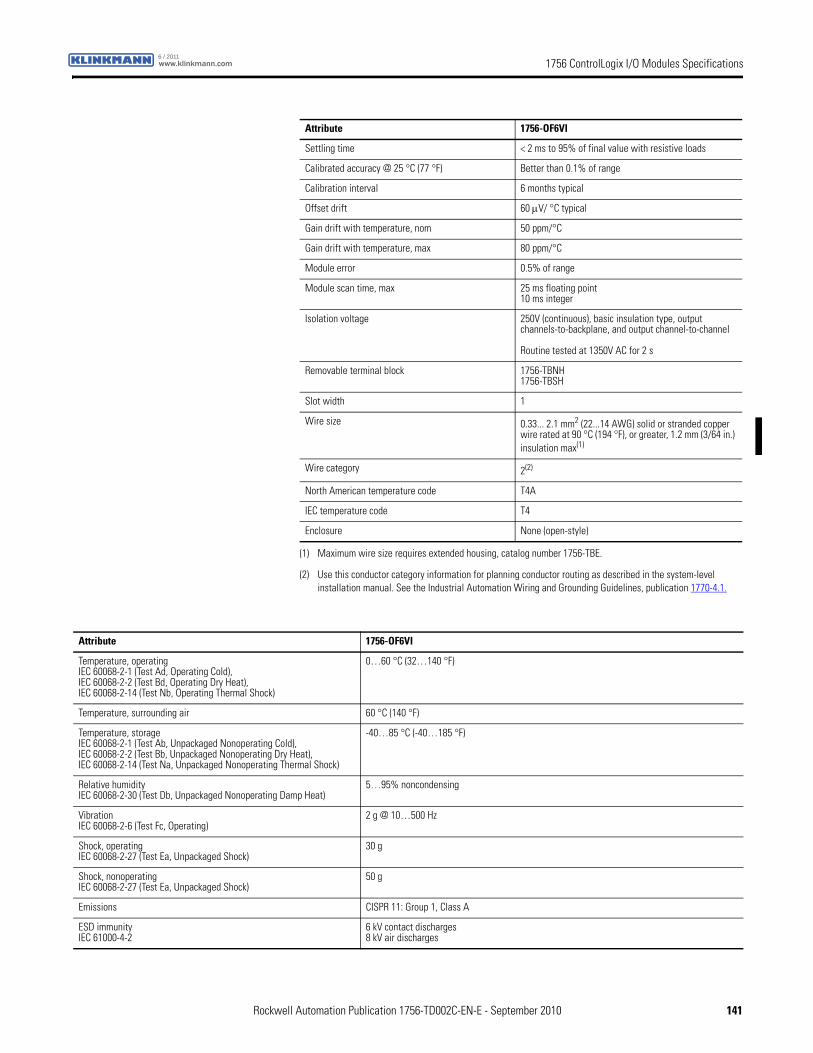
1756 ControlLogix I/O Modules Specificationswww.klinkmann.com6 / 2011
Settling time < 2 ms to 95% of final value with resistive loads
Calibrated accuracy @ 25 °C (77 °F) Better than 0.1% of range
Calibration interval 6 months typical
Offset drift 60 μV/ °C typical
Gain drift with temperature, nom 50 ppm/°C
Gain drift with temperature, max 80 ppm/°C
Module error 0.5% of range
Module scan time, max 25 ms floating point10 ms integer
Isolation voltage 250V (continuous), basic insulation type, output channels-to-backplane, and output channel-to-channel
Routine tested at 1350V AC for 2 s
Removable terminal block 1756-TBNH1756-TBSH
Slot width 1
Wire size 0.33... 2.1 mm2 (22...14 AWG) solid or stranded copper wire rated at 90 °C (194 °F), or greater, 1.2 mm (3/64 in.) insulation max(1)
Wire category 2(2)
North American temperature code T4A
IEC temperature code T4
Enclosure None (open-style)
(1) Maximum wire size requires extended housing, catalog number 1756-TBE.
(2) Use this conductor category information for planning conductor routing as described in the system-level installation manual. See the Industrial Automation Wiring and Grounding Guidelines, publication 1770-4.1.
Attribute 1756-OF6VI
Attribute 1756-OF6VI
Temperature, operatingIEC 60068-2-1 (Test Ad, Operating Cold),IEC 60068-2-2 (Test Bd, Operating Dry Heat),IEC 60068-2-14 (Test Nb, Operating Thermal Shock)
0…60 °C (32…140 °F)
Temperature, surrounding air 60 °C (140 °F)
Temperature, storageIEC 60068-2-1 (Test Ab, Unpackaged Nonoperating Cold),IEC 60068-2-2 (Test Bb, Unpackaged Nonoperating Dry Heat),IEC 60068-2-14 (Test Na, Unpackaged Nonoperating Thermal Shock)
-40…85 °C (-40…185 °F)
Relative humidityIEC 60068-2-30 (Test Db, Unpackaged Nonoperating Damp Heat)
5…95% noncondensing
VibrationIEC 60068-2-6 (Test Fc, Operating)
2 g @ 10…500 Hz
Shock, operatingIEC 60068-2-27 (Test Ea, Unpackaged Shock)
30 g
Shock, nonoperatingIEC 60068-2-27 (Test Ea, Unpackaged Shock)
50 g
Emissions CISPR 11: Group 1, Class A
ESD immunityIEC 61000-4-2
6 kV contact discharges8 kV air discharges
Rockwell Automation Publication 1756-TD002C-EN-E - September 2010 141
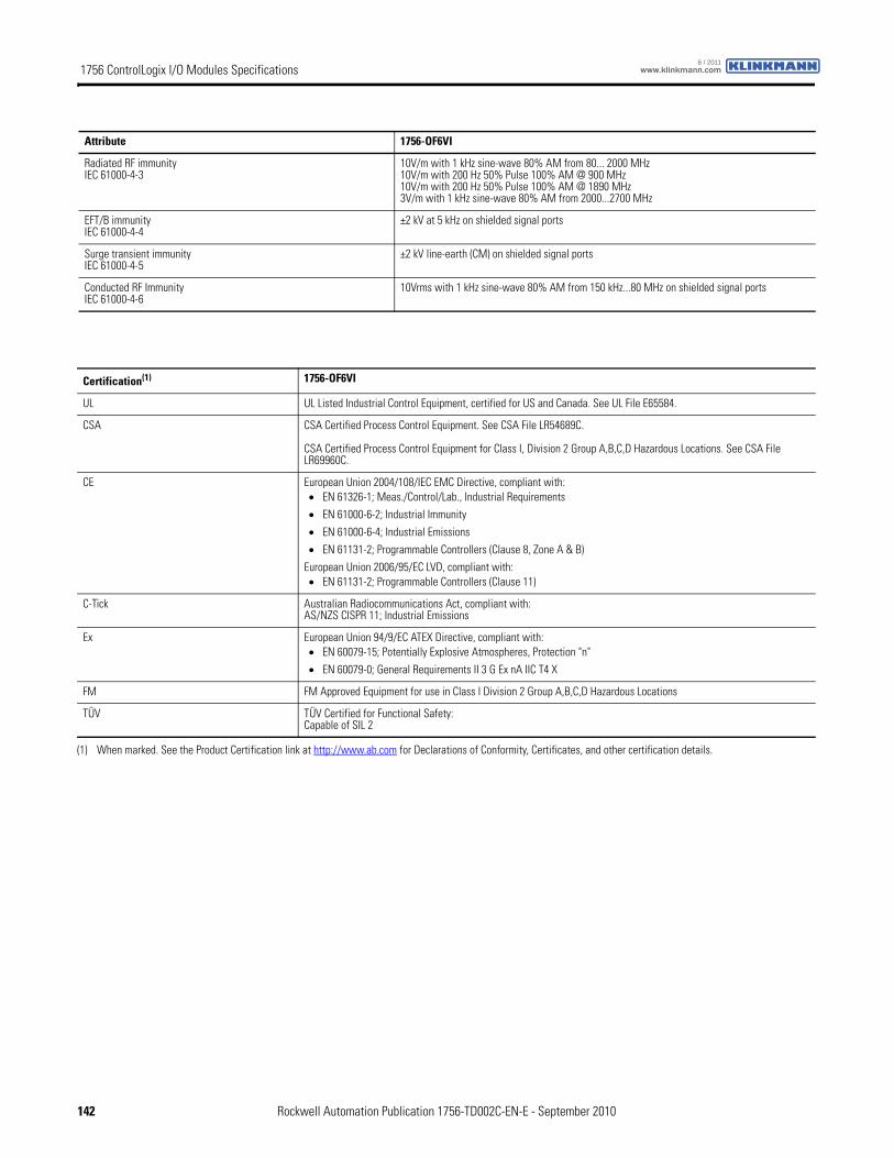
1756 ControlLogix I/O Modules Specifications www.klinkmann.com6 / 2011
Radiated RF immunityIEC 61000-4-3
10V/m with 1 kHz sine-wave 80% AM from 80... 2000 MHz10V/m with 200 Hz 50% Pulse 100% AM @ 900 MHz10V/m with 200 Hz 50% Pulse 100% AM @ 1890 MHz3V/m with 1 kHz sine-wave 80% AM from 2000...2700 MHz
EFT/B immunityIEC 61000-4-4
±2 kV at 5 kHz on shielded signal ports
Surge transient immunityIEC 61000-4-5
±2 kV line-earth (CM) on shielded signal ports
Conducted RF ImmunityIEC 61000-4-6
10Vrms with 1 kHz sine-wave 80% AM from 150 kHz...80 MHz on shielded signal ports
Attribute 1756-OF6VI
Certification(1) 1756-OF6VI
UL UL Listed Industrial Control Equipment, certified for US and Canada. See UL File E65584.
CSA CSA Certified Process Control Equipment. See CSA File LR54689C.
CSA Certified Process Control Equipment for Class I, Division 2 Group A,B,C,D Hazardous Locations. See CSA File LR69960C.
CE European Union 2004/108/IEC EMC Directive, compliant with:• EN 61326-1; Meas./Control/Lab., Industrial Requirements
• EN 61000-6-2; Industrial Immunity
• EN 61000-6-4; Industrial Emissions
• EN 61131-2; Programmable Controllers (Clause 8, Zone A & B)
European Union 2006/95/EC LVD, compliant with:• EN 61131-2; Programmable Controllers (Clause 11)
C-Tick Australian Radiocommunications Act, compliant with:AS/NZS CISPR 11; Industrial Emissions
Ex European Union 94/9/EC ATEX Directive, compliant with:• EN 60079-15; Potentially Explosive Atmospheres, Protection "n"
• EN 60079-0; General Requirements II 3 G Ex nA IIC T4 X
FM FM Approved Equipment for use in Class I Division 2 Group A,B,C,D Hazardous Locations
TÜV TÜV Certified for Functional Safety:Capable of SIL 2
(1) When marked. See the Product Certification link at http://www.ab.com for Declarations of Conformity, Certificates, and other certification details.
142 Rockwell Automation Publication 1756-TD002C-EN-E - September 2010
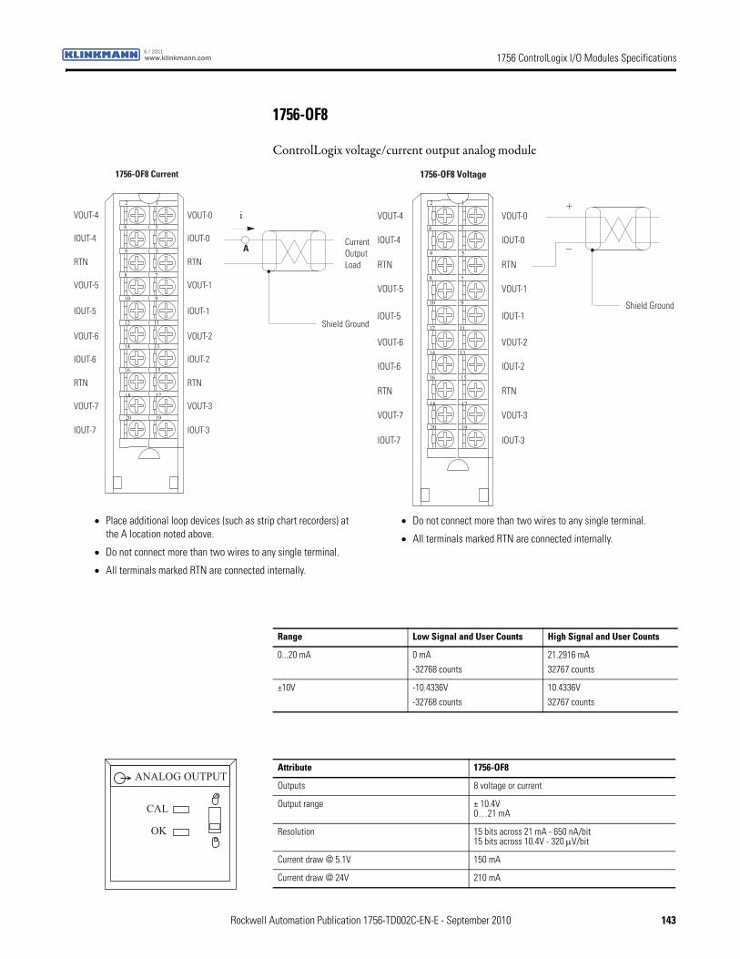
1756 ControlLogix I/O Modules Specificationswww.klinkmann.com6 / 2011
1756-OF8
ControlLogix voltage/current output analog module
12
34
56
78
910
1112
1314
1516
1718
1920
Shield Ground
i
Current OutputLoad
1756-OF8 Current
VOUT-4
IOUT-4
RTN
VOUT-5
VOUT-6
IOUT-6
RTN
VOUT-7
IOUT-5
IOUT-7
VOUT-0
IOUT-0
RTN
VOUT-1
VOUT-2
IOUT-2
RTN
VOUT-3
IOUT-1
IOUT-3
A
12
34
56
78
910
1112
1314
1516
1718
1920
+
–
Shield Ground
1756-OF8 Voltage
VOUT-4
IOUT-4
RTN
VOUT-5
VOUT-6
IOUT-6
RTN
VOUT-7
IOUT-5
IOUT-7
VOUT-0
IOUT-0
RTN
VOUT-1
VOUT-2
IOUT-2
RTN
VOUT-3
IOUT-1
IOUT-3
• Place additional loop devices (such as strip chart recorders) at the A location noted above.
• Do not connect more than two wires to any single terminal.
• All terminals marked RTN are connected internally.
• Do not connect more than two wires to any single terminal.
• All terminals marked RTN are connected internally.
Range Low Signal and User Counts High Signal and User Counts
0...20 mA 0 mA
-32768 counts
21.2916 mA
32767 counts
±10V -10.4336V
-32768 counts
10.4336V
32767 counts
Attribute 1756-OF8
Outputs 8 voltage or current
Output range ± 10.4V0…21 mA
Resolution 15 bits across 21 mA - 650 nA/bit15 bits across 10.4V - 320 μV/bit
Current draw @ 5.1V 150 mA
Current draw @ 24V 210 mA
ANALOG OUTPUT
CAL
OK
Rockwell Automation Publication 1756-TD002C-EN-E - September 2010 143
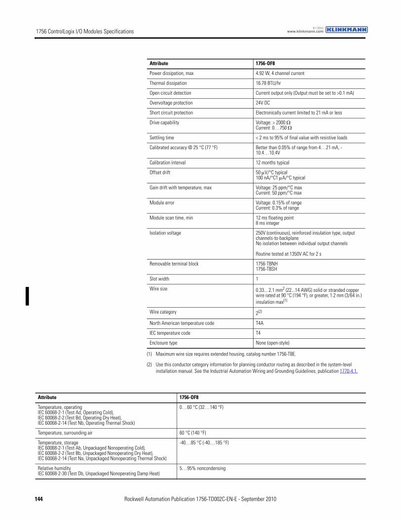
1756 ControlLogix I/O Modules Specifications www.klinkmann.com6 / 2011
Power dissipation, max 4.92 W, 4 channel current
Thermal dissipation 16.78 BTU/hr
Open circuit detection Current output only (Output must be set to >0.1 mA)
Overvoltage protection 24V DC
Short circuit protection Electronically current limited to 21 mA or less
Drive capability Voltage: > 2000 Ω Current: 0…750 Ω
Settling time < 2 ms to 95% of final value with resistive loads
Calibrated accuracy @ 25 °C (77 °F) Better than 0.05% of range from 4…21 mA, -10.4…10.4V
Calibration interval 12 months typical
Offset drift 50 μV/°C typical100 nA/°C1 μA/°C typical
Gain drift with temperature, max Voltage: 25 ppm/°C maxCurrent: 50 ppm/°C max
Module error Voltage: 0.15% of rangeCurrent: 0.3% of range
Module scan time, min 12 ms floating point8 ms integer
Isolation voltage 250V (continuous), reinforced insulation type, output channels-to-backplaneNo isolation between individual output channels
Routine tested at 1350V AC for 2 s
Removable terminal block 1756-TBNH1756-TBSH
Slot width 1
Wire size 0.33... 2.1 mm2 (22...14 AWG) solid or stranded copper wire rated at 90 °C (194 °F), or greater, 1.2 mm (3/64 in.) insulation max(1)
Wire category 2(2)
North American temperature code T4A
IEC temperature code T4
Enclosure type None (open-style)
(1) Maximum wire size requires extended housing, catalog number 1756-TBE.
(2) Use this conductor category information for planning conductor routing as described in the system-level installation manual. See the Industrial Automation Wiring and Grounding Guidelines, publication 1770-4.1.
Attribute 1756-OF8
Attribute 1756-OF8
Temperature, operatingIEC 60068-2-1 (Test Ad, Operating Cold),IEC 60068-2-2 (Test Bd, Operating Dry Heat),IEC 60068-2-14 (Test Nb, Operating Thermal Shock)
0…60 °C (32…140 °F)
Temperature, surrounding air 60 °C (140 °F)
Temperature, storageIEC 60068-2-1 (Test Ab, Unpackaged Nonoperating Cold),IEC 60068-2-2 (Test Bb, Unpackaged Nonoperating Dry Heat),IEC 60068-2-14 (Test Na, Unpackaged Nonoperating Thermal Shock)
-40…85 °C (-40…185 °F)
Relative humidityIEC 60068-2-30 (Test Db, Unpackaged Nonoperating Damp Heat)
5…95% noncondensing
144 Rockwell Automation Publication 1756-TD002C-EN-E - September 2010
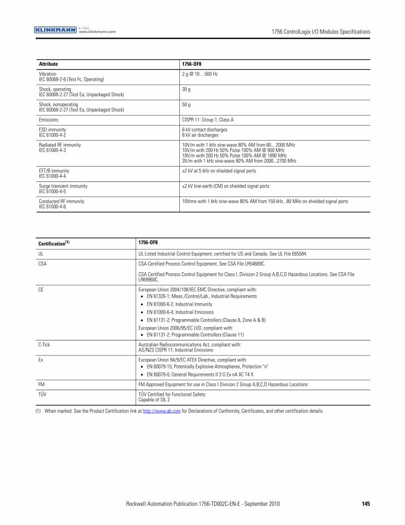
1756 ControlLogix I/O Modules Specificationswww.klinkmann.com6 / 2011
VibrationIEC 60068-2-6 (Test Fc, Operating)
2 g @ 10…500 Hz
Shock, operatingIEC 60068-2-27 (Test Ea, Unpackaged Shock)
30 g
Shock, nonoperatingIEC 60068-2-27 (Test Ea, Unpackaged Shock)
50 g
Emissions CISPR 11: Group 1, Class A
ESD immunityIEC 61000-4-2
6 kV contact discharges8 kV air discharges
Radiated RF immunityIEC 61000-4-3
10V/m with 1 kHz sine-wave 80% AM from 80... 2000 MHz10V/m with 200 Hz 50% Pulse 100% AM @ 900 MHz10V/m with 200 Hz 50% Pulse 100% AM @ 1890 MHz3V/m with 1 kHz sine-wave 80% AM from 2000...2700 MHz
EFT/B immunityIEC 61000-4-4
±2 kV at 5 kHz on shielded signal ports
Surge transient immunityIEC 61000-4-5
±2 kV line-earth (CM) on shielded signal ports
Conducted RF immunityIEC 61000-4-6
10Vrms with 1 kHz sine-wave 80% AM from 150 kHz...80 MHz on shielded signal ports
Attribute 1756-OF8
Certification(1) 1756-OF8
UL UL Listed Industrial Control Equipment, certified for US and Canada. See UL File E65584.
CSA CSA Certified Process Control Equipment. See CSA File LR54689C.
CSA Certified Process Control Equipment for Class I, Division 2 Group A,B,C,D Hazardous Locations. See CSA File LR69960C.
CE European Union 2004/108/IEC EMC Directive, compliant with:• EN 61326-1; Meas./Control/Lab., Industrial Requirements
• EN 61000-6-2; Industrial Immunity
• EN 61000-6-4; Industrial Emissions
• EN 61131-2; Programmable Controllers (Clause 8, Zone A & B)
European Union 2006/95/EC LVD, compliant with:• EN 61131-2; Programmable Controllers (Clause 11)
C-Tick Australian Radiocommunications Act, compliant with:AS/NZS CISPR 11; Industrial Emissions
Ex European Union 94/9/EC ATEX Directive, compliant with:• EN 60079-15; Potentially Explosive Atmospheres, Protection "n"
• EN 60079-0; General Requirements II 3 G Ex nA IIC T4 X
FM FM Approved Equipment for use in Class I Division 2 Group A,B,C,D Hazardous Locations
TÜV TÜV Certified for Functional Safety:Capable of SIL 2
(1) When marked. See the Product Certification link at http://www.ab.com for Declarations of Conformity, Certificates, and other certification details.
Rockwell Automation Publication 1756-TD002C-EN-E - September 2010 145
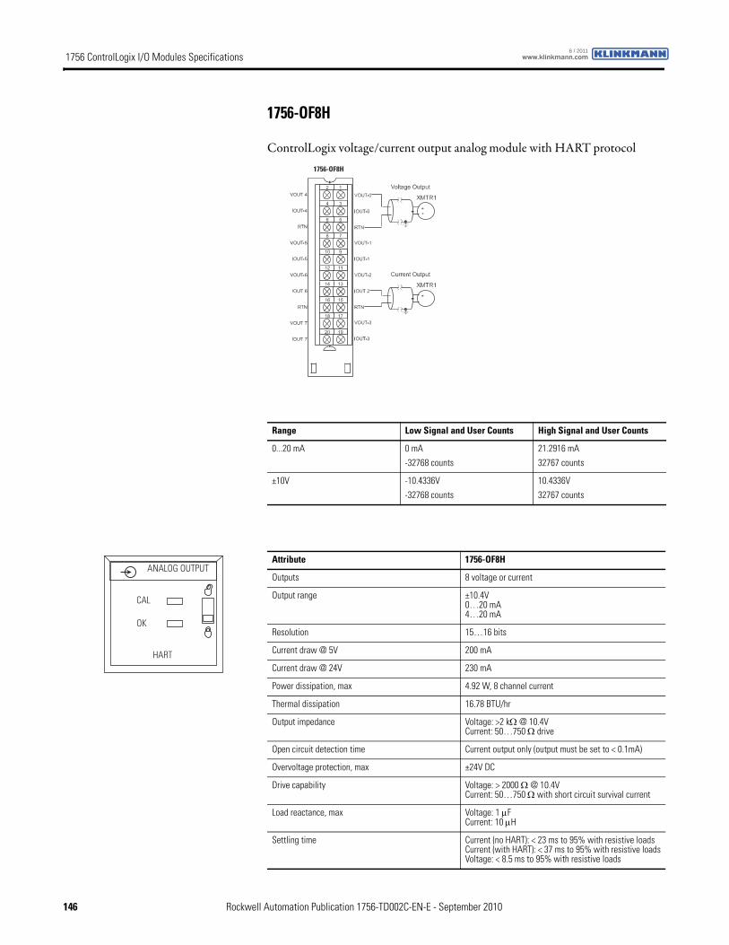
1756 ControlLogix I/O Modules Specifications www.klinkmann.com6 / 2011
1756-OF8H
ControlLogix voltage/current output analog module with HART protocol1756-OF8H
Range Low Signal and User Counts High Signal and User Counts
0...20 mA 0 mA
-32768 counts
21.2916 mA
32767 counts
±10V -10.4336V
-32768 counts
10.4336V
32767 counts
Attribute 1756-OF8H
Outputs 8 voltage or current
Output range ±10.4V0…20 mA4…20 mA
Resolution 15…16 bits
Current draw @ 5V 200 mA
Current draw @ 24V 230 mA
Power dissipation, max 4.92 W, 8 channel current
Thermal dissipation 16.78 BTU/hr
Output impedance Voltage: >2 kΩ @ 10.4VCurrent: 50…750 Ω drive
Open circuit detection time Current output only (output must be set to < 0.1mA)
Overvoltage protection, max ±24V DC
Drive capability Voltage: > 2000 Ω @ 10.4VCurrent: 50…750 Ω with short circuit survival current
Load reactance, max Voltage: 1 μFCurrent: 10 μH
Settling time Current (no HART): < 23 ms to 95% with resistive loadsCurrent (with HART): < 37 ms to 95% with resistive loadsVoltage: < 8.5 ms to 95% with resistive loads
ANALOG OUTPUT
CAL
OK
HART
146 Rockwell Automation Publication 1756-TD002C-EN-E - September 2010
1756 ControlLogix I/O Modules Specificationswww.klinkmann.com6 / 2011
Calibrated accuracy @ 25 °C (77 °F) Voltage: Better than 0.05% of rangeCurrent: Better than 0.15% of range
Calibration interval 12 months typical
Offset drift 100 μV/°C typical200 nA/°C typical
Gain drift with temperature Voltage: 20 ppm/°CCurrent: 35 ppm/°C
Module error Voltage: 0.15% of rangeCurrent: 0.3% of range
Module output scan time, min 12 ms floating point
Module HART scan time Typically 1 s per HART channel enabledEstimate 10 s if all 8 channels have HART enabledPass through messages, handheld communicators, secondary masters, communication errors, or configuration changes can significantly increase the update time
Isolation voltage 50V (continuous), basic insulation type, output channels-to-backplaneNo isolation between individual output channels
Type tested at 1500V AC for 60 s
Removable terminal block 1756-TBNH1756-TBSH
Slot width 1
Wire size 0.33... 2.1 mm2 (22...14 AWG) solid or stranded copper wire rated at 90 °C (194 °F), or greater, 1.2 mm (3/64 in.) insulation max(1)
Wire category 2(2)
North American temperature code T4A
IEC temperature code T4
Enclosure type None (open-style)
(1) Maximum wire size requires extended housing, catalog number 1756-TBE.
(2) Use this conductor category information for planning conductor routing as described in the system-level installation manual. See the Industrial Automation Wiring and Grounding Guidelines, publication 1770-4.1.
Attribute 1756-OF8H
Attribute 1756-OF8H
Temperature, operatingIEC 60068-2-1 (Test Ad, Operating Cold),IEC 60068-2-2 (Test Bd, Operating Dry Heat),IEC 60068-2-14 (Test Nb, Operating Thermal Shock)
0…60 °C (32…140 °F)
Temperature, surrounding air 60 °C (140 °F)
Temperature, storageIEC 60068-2-1 (Test Ab, Unpackaged Nonoperating Cold),IEC 60068-2-2 (Test Bb, Unpackaged Nonoperating Dry Heat),IEC 60068-2-14 (Test Na, Unpackaged Nonoperating Thermal Shock)
-40…85 °C (-40…185 °F)
Relative humidityIEC 60068-2-30 (Test Db, Unpackaged Nonoperating Damp Heat)
5…95% noncondensing
VibrationIEC 60068-2-6 (Test Fc, Operating)
2 g @ 10…500 Hz
Shock, operatingIEC 60068-2-27 (Test Ea, Unpackaged Shock)
30 g
Shock, nonoperatingIEC 60068-2-27 (Test Ea, Unpackaged Shock)
50 g
Rockwell Automation Publication 1756-TD002C-EN-E - September 2010 147
1756 ControlLogix I/O Modules Specifications www.klinkmann.com6 / 2011
Emissions CISPR 11: Group 1, Class A
ESD immunityIEC 61000-4-2
6 kV contact discharges8 kV air discharges
Radiated RF immunityIEC 61000-4-3
10V/m with 1 kHz sine-wave 80% AM from 80... 2000 MHz10V/m with 200 Hz 50% Pulse 100% AM @ 900 MHz10V/m with 200 Hz 50% Pulse 100% AM @ 1890 MHz3V/m with 1 kHz sine-wave 80% AM from 2000...2700 MHz
EFT/B immunityIEC 61000-4-4
±2 kV at 5 kHz on shielded signal ports
Surge transient immunityIEC 61000-4-5
±2 kV line-earth (CM) on shielded signal ports
Conducted RF immunityIEC 61000-4-6
10Vrms with 1 kHz sine-wave 80% AM from 150 kHz...80 MHz on shielded signal ports
Attribute 1756-OF8H
Certification(1) 1756-OF8H
c-UL-us UL Listed Industrial Control Equipment, certified for US and Canada. See UL File E65584.
CSA CSA Certified Process Control Equipment for Class I, Division 2 Group A,B,C,D Hazardous Locations. See CSA File LR101622C.
CE European Union 2004/108/IEC EMC Directive, compliant with:• EN 61326-1; Meas./Control/Lab., Industrial Requirements
• EN 61000-6-2; Industrial Immunity
• EN 61000-6-4; Industrial Emissions
• EN 61131-2; Programmable Controllers (Clause 8, Zone A & B)
C-Tick Australian Radiocommunications Act, compliant with:AS/NZS CISPR 11; Industrial Emissions
Ex European Union 94/9/EC ATEX Directive, compliant with:• EN 60079-15; Potentially Explosive Atmospheres, Protection "n"
• EN 60079-0; General Requirements II 3 G Ex nA IIC T4 X
FM FM Approved Equipment for use in Class I Division 2 Group A,B,C,D Hazardous Locations
TÜV TÜV Certified for Functional Safety:Capable of SIL 2
(1) When marked. See the Product Certification link at http://www.ab.com for Declarations of Conformity, Certificates, and other certification details.
148 Rockwell Automation Publication 1756-TD002C-EN-E - September 2010
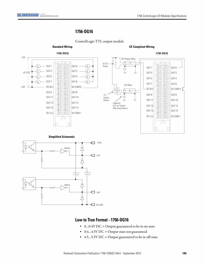
1756 ControlLogix I/O Modules Specificationswww.klinkmann.com6 / 2011
1756-OG16
ControlLogix TTL output module
Low to True Format - 1756-OG16• 0…0.4V DC = Output guaranteed to be in on-state• 0.4…4.5V DC = Output state not guaranteed• 4.5…5.5V DC = Output guaranteed to be in off-state
1
3
5
7
9
19
17
15
13
11
2
4
6
8
10
20
18
16
14
12
OUT-1
OUT-3
OUT-5
OUT-7
DC-0(+)
OUT-0
OUT-2
OUT-4
OUT-6
DC COM 0
OUT-9
OUT-11
OUT-13
OUT-15
DC-1(+)
OUT-8
OUT-10
OUT-12
OUT-14
DC COM 1
– DC
+ DC
+5 V DC
1756-OG16
1
3
5
7
9
19
17
15
13
11
2
4
6
8
10
20
18
16
14
12
OUT-1
OUT-3
OUT-5
OUT-7
DC-0(+)
OUT-0
OUT-2
OUT-4
OUT-6
DC COM 0
OUT-9
OUT-11
OUT-13
OUT-15
DC-1(+)
OUT-8
OUT-10
OUT-12
OUT-14
DC COM 1
Capacitor0.01 μF Typical (See notes below.)
DC Power Wire
I/O Wire
5V DC Power
+
–
+
–TTL Output Device
1756-OG16
DC COM
OUT
74AC14
OUT
+5 DC
74AC14
Standard Wiring CE Compliant Wiring
Simplified Schematic
Rockwell Automation Publication 1756-TD002C-EN-E - September 2010 149
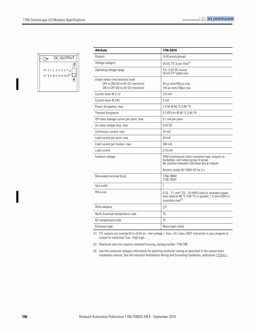
1756 ControlLogix I/O Modules Specifications www.klinkmann.com6 / 2011
Attribute 1756-OG16
Outputs 16 (8 points/group)
Voltage category 5V DC TTL (Low=True(1)
(1) TTL outputs are inverted (0 to +0.4V dc = low voltage = True = On.) Use a NOT instruction in your program to convert to traditional True - High logic.
Operating voltage range 4.5...5.5V DC source50 mV P-P ripple max
Output delay time (resistive load)OFF to ON (5V-to-0V DC transition)ON to OFF (0V-to-5V DC transition)
45 µs nom/450 µs max145 µs nom/700µs max
Current draw @ 5.1V 210 mA
Current draw @ 24V 2 mA
Power dissipation, max 1.5 W @ 60 °C (140 °F)
Thermal dissipation 5.2 BTU/hr @ 60 °C (140 °F)
Off-state leakage current per point, max 0.1 mA per point
On-state voltage drop, max 0.4V DC
Continuous current, max 24 mA
Load current per point, max 24 mA
Load current per module, max 384 mA
Load current 0.15 mA
Isolation voltage 250V (continuous), basic insulation type, outputs-to-backplane, and output group-to-groupNo isolation between individual group outputs
Routine tested @ 1350V AC for 2 s
Removable terminal block 1756-TBNH1756-TBSH
Slot width 1
Wire size 0.33... 2.1 mm2 (22...14 AWG) solid or stranded copper wire rated at 90 °C (194 °F), or greater, 1.2 mm (3/64 in.) insulation max(2)
(2) Maximum wire size requires extended housing, catalog number 1756-TBE.
Wire category 2(3)
(3) Use this conductor category information for planning conductor routing as described in the system-level installation manual. See the Industrial Automation Wiring and Grounding Guidelines, publication 1770-4.1.
North American temperature code T5
IEC temperature code T5
Enclosure type None (open-style)
DC OUTPUT
ST 0 1 2 3 4 5 6 7
ST 8 9 10 11 12 13 14 15
OK
150 Rockwell Automation Publication 1756-TD002C-EN-E - September 2010
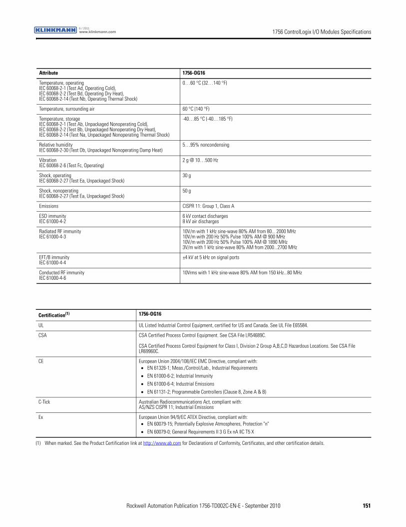
1756 ControlLogix I/O Modules Specificationswww.klinkmann.com6 / 2011
Attribute 1756-OG16
Temperature, operatingIEC 60068-2-1 (Test Ad, Operating Cold),IEC 60068-2-2 (Test Bd, Operating Dry Heat),IEC 60068-2-14 (Test Nb, Operating Thermal Shock)
0…60 °C (32…140 °F)
Temperature, surrounding air 60 °C (140 °F)
Temperature, storageIEC 60068-2-1 (Test Ab, Unpackaged Nonoperating Cold),IEC 60068-2-2 (Test Bb, Unpackaged Nonoperating Dry Heat),IEC 60068-2-14 (Test Na, Unpackaged Nonoperating Thermal Shock)
-40…85 °C (-40…185 °F)
Relative humidityIEC 60068-2-30 (Test Db, Unpackaged Nonoperating Damp Heat)
5…95% noncondensing
VibrationIEC 60068-2-6 (Test Fc, Operating)
2 g @ 10…500 Hz
Shock, operatingIEC 60068-2-27 (Test Ea, Unpackaged Shock)
30 g
Shock, nonoperatingIEC 60068-2-27 (Test Ea, Unpackaged Shock)
50 g
Emissions CISPR 11: Group 1, Class A
ESD immunityIEC 61000-4-2
6 kV contact discharges8 kV air discharges
Radiated RF immunityIEC 61000-4-3
10V/m with 1 kHz sine-wave 80% AM from 80... 2000 MHz10V/m with 200 Hz 50% Pulse 100% AM @ 900 MHz10V/m with 200 Hz 50% Pulse 100% AM @ 1890 MHz3V/m with 1 kHz sine-wave 80% AM from 2000...2700 MHz
EFT/B immunityIEC 61000-4-4
±4 kV at 5 kHz on signal ports
Conducted RF immunityIEC 61000-4-6
10Vrms with 1 kHz sine-wave 80% AM from 150 kHz...80 MHz
Certification(1) 1756-OG16
UL UL Listed Industrial Control Equipment, certified for US and Canada. See UL File E65584.
CSA CSA Certified Process Control Equipment. See CSA File LR54689C.
CSA Certified Process Control Equipment for Class I, Division 2 Group A,B,C,D Hazardous Locations. See CSA File LR69960C.
CE European Union 2004/108/IEC EMC Directive, compliant with:• EN 61326-1; Meas./Control/Lab., Industrial Requirements
• EN 61000-6-2; Industrial Immunity
• EN 61000-6-4; Industrial Emissions
• EN 61131-2; Programmable Controllers (Clause 8, Zone A & B)
C-Tick Australian Radiocommunications Act, compliant with:AS/NZS CISPR 11; Industrial Emissions
Ex European Union 94/9/EC ATEX Directive, compliant with:• EN 60079-15; Potentially Explosive Atmospheres, Protection "n"
• EN 60079-0; General Requirements II 3 G Ex nA IIC T5 X
(1) When marked. See the Product Certification link at http://www.ab.com for Declarations of Conformity, Certificates, and other certification details.
Rockwell Automation Publication 1756-TD002C-EN-E - September 2010 151
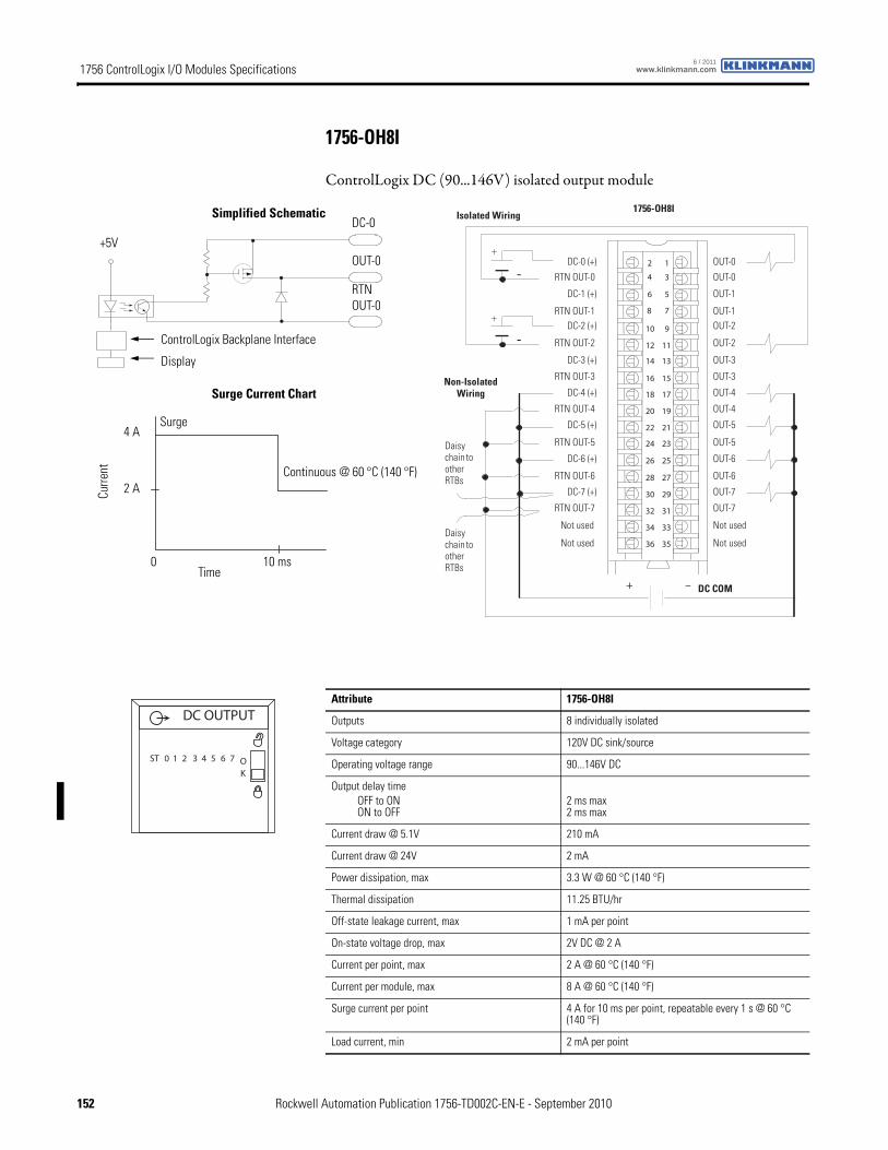
1756 ControlLogix I/O Modules Specifications www.klinkmann.com6 / 2011
1756-OH8I
ControlLogix DC (90...146V) isolated output module
12
34
56
78
910
1112
1314
1516
1718
1920
2122
2324
2526
2728
2930
3132
3334
3536
+
+
-
-
+ –
DC-0 (+)
RTN OUT-0
DC-1 (+)
RTN OUT-1
DC-4 (+)
DC-2 (+)
RTN OUT-2
DC-3 (+)
RTN OUT-3
Not used
RTN OUT-4
DC-5 (+)
RTN OUT-5
DC-6 (+)
RTN OUT-6
DC-7 (+)
RTN OUT-7
Not used
OUT-0
OUT-0
OUT-1
OUT-1
OUT-4
OUT-2
OUT-2
OUT-3
OUT-3
Not used
OUT-4
OUT-5
OUT-5
OUT-6
OUT-6
OUT-7
OUT-7
Not used
DC COM
Isolated Wiring
Daisy chain to other RTBs
Non-Isolated Wiring
1756-OH8I
Daisy chain to other RTBs
ControlLogix Backplane Interface
RTNOUT-0
DC-0
Display
Surge Current Chart
Simplified Schematic
Surge
+5V
Curre
nt
Time0 10 ms
2 A
4 A
OUT-0
Continuous @ 60 °C (140 °F)
Attribute 1756-OH8I
Outputs 8 individually isolated
Voltage category 120V DC sink/source
Operating voltage range 90...146V DC
Output delay timeOFF to ONON to OFF
2 ms max 2 ms max
Current draw @ 5.1V 210 mA
Current draw @ 24V 2 mA
Power dissipation, max 3.3 W @ 60 °C (140 °F)
Thermal dissipation 11.25 BTU/hr
Off-state leakage current, max 1 mA per point
On-state voltage drop, max 2V DC @ 2 A
Current per point, max 2 A @ 60 °C (140 °F)
Current per module, max 8 A @ 60 °C (140 °F)
Surge current per point 4 A for 10 ms per point, repeatable every 1 s @ 60 °C (140 °F)
Load current, min 2 mA per point
DC OUTPUT
ST 0 1 2 3 4 5 6 7 OK
152 Rockwell Automation Publication 1756-TD002C-EN-E - September 2010

1756 ControlLogix I/O Modules Specificationswww.klinkmann.com6 / 2011
Isolation voltage 250V (continuous), basic insulation type, outputs-to-backplane, and output-to-output
Routine tested @ 1350V AC for 2 s
Removable terminal block 1756-TBCH1756-TBS6H
Slot width 1
Wire size 0.33... 2.1 mm2 (22...14 AWG) solid or stranded copper wire rated at 90 °C (194 °F), or greater, 1.2 mm (3/64 in.) insulation max(1)
Wire category 1(2)
North American temperature code T4A
Enclosure type None (open-style)
(1) Maximum wire size requires extended housing, catalog number 1756-TBE.
(2) Use this conductor category information for planning conductor routing as described in the system-level installation manual. See the Industrial Automation Wiring and Grounding Guidelines, publication 1770-4.1.
Attribute 1756-OH8I
Attribute 1756-OH8I
Temperature, operatingIEC 60068-2-1 (Test Ad, Operating Cold),IEC 60068-2-2 (Test Bd, Operating Dry Heat),IEC 60068-2-14 (Test Nb, Operating Thermal Shock)
0…60 °C (32…140 °F)
Temperature, surrounding air 60 °C (140 °F)
Temperature, storageIEC 60068-2-1 (Test Ab, Unpackaged Nonoperating Cold),IEC 60068-2-2 (Test Bb, Unpackaged Nonoperating Dry Heat),IEC 60068-2-14 (Test Na, Unpackaged Nonoperating Thermal Shock)
-40…85 °C (-40…185 °F)
Relative humidityIEC 60068-2-30 (Test Db, Unpackaged Nonoperating Damp Heat)
5…95% noncondensing
VibrationIEC 60068-2-6 (Test Fc, Operating)
2 g @ 10…500 Hz
Shock, operatingIEC 60068-2-27 (Test Ea, Unpackaged Shock)
30 g
Shock, nonoperatingIEC 60068-2-27 (Test Ea, Unpackaged Shock)
50 g
Emissions CISPR 11: Group 1, Class A
ESD immunityIEC 61000-4-2
6 kV contact discharges8 kV air discharges
Radiated RF immunityIEC 61000-4-3
10V/m with 1 kHz sine-wave 80% AM from 80... 2000 MHz10V/m with 200 Hz 50% Pulse 100% AM @ 900 MHz10V/m with 200 Hz 50% Pulse 100% AM @ 1890 MHz3V/m with 1 kHz sine-wave 80% AM from 2000...2700 MHz
EFT/B immunityIEC 61000-4-4
±4 kV at 5 kHz on signal ports
Surge transient immunityIEC 61000-4-5
±1 kV line-line (DM) and ±2 kV line-earth (CM) on signal ports
Conducted RF immunityIEC 61000-4-6
10Vrms with 1 kHz sine-wave 80% AM from 150 kHz...80 MHz
Rockwell Automation Publication 1756-TD002C-EN-E - September 2010 153

1756 ControlLogix I/O Modules Specifications www.klinkmann.com6 / 2011
Certification(1) 1756-OH8I
UL UL Listed Industrial Control Equipment, certified for US and Canada. See UL File E65584.
CSA CSA Certified Process Control Equipment. See CSA File LR54689C.
CSA Certified Process Control Equipment for Class I, Division 2 Group A,B,C,D Hazardous Locations. See CSA File LR69960C.
CE European Union 2004/108/IEC EMC Directive, compliant with:• EN 61326-1; Meas./Control/Lab., Industrial Requirements
• EN 61000-6-2; Industrial Immunity
• EN 61000-6-4; Industrial Emissions
• EN 61131-2; Programmable Controllers (Clause 8, Zone A & B)
European Union 2006/95/EC LVD, compliant with:• EN 61131-2; Programmable Controllers
C-Tick Australian Radiocommunications Act, compliant with:AS/NZS CISPR 11; Industrial Emissions
FM FM Approved Equipment for use in Class I Division 2 Group A,B,C,D Hazardous Locations
(1) When marked. See the Product Certification link at http://www.ab.com for Declarations of Conformity, Certificates, and other certification details.
154 Rockwell Automation Publication 1756-TD002C-EN-E - September 2010
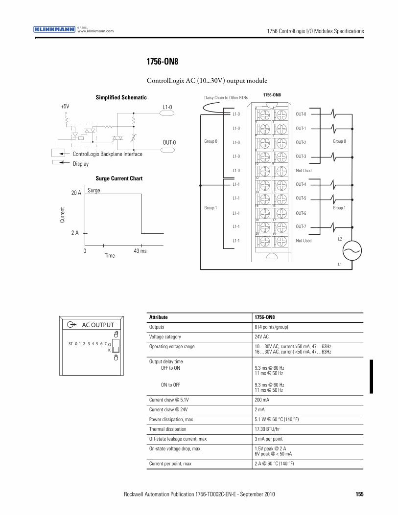
1756 ControlLogix I/O Modules Specificationswww.klinkmann.com6 / 2011
1756-ON8
ControlLogix AC (10...30V) output module
12
34
56
78
910
1112
1314
1516
1718
1920
Daisy Chain to Other RTBs
Group 0Group 0
Group 1Group 1
1756-ON8
L1-0
L1-0
L1-0
L1-0
L1-1
L1-1
L1-1
L1-1
L1-0
L1-1
OUT-0
OUT-1
OUT-2
OUT-3
OUT-4
OUT-5
OUT-6
OUT-7
Not Used
Not Used
L1
L2
ControlLogix Backplane Interface
OUT-0
L1-0
Display
Surge Current Chart
Simplified Schematic
Surge
+5V
Curre
nt
Time0 43 ms
2 A
20 A
Attribute 1756-ON8
Outputs 8 (4 points/group)
Voltage category 24V AC
Operating voltage range 10…30V AC, current >50 mA, 47…63Hz16…30V AC, current <50 mA, 47…63Hz
Output delay timeOFF to ON
ON to OFF
9.3 ms @ 60 Hz11 ms @ 50 Hz 9.3 ms @ 60 Hz11 ms @ 50 Hz
Current draw @ 5.1V 200 mA
Current draw @ 24V 2 mA
Power dissipation, max 5.1 W @ 60 °C (140 °F)
Thermal dissipation 17.39 BTU/hr
Off-state leakage current, max 3 mA per point
On-state voltage drop, max 1.5V peak @ 2 A6V peak @ < 50 mA
Current per point, max 2 A @ 60 °C (140 °F)
ST 0 1 2 3 4 5 6 7 OK
AC OUTPUT
Rockwell Automation Publication 1756-TD002C-EN-E - September 2010 155
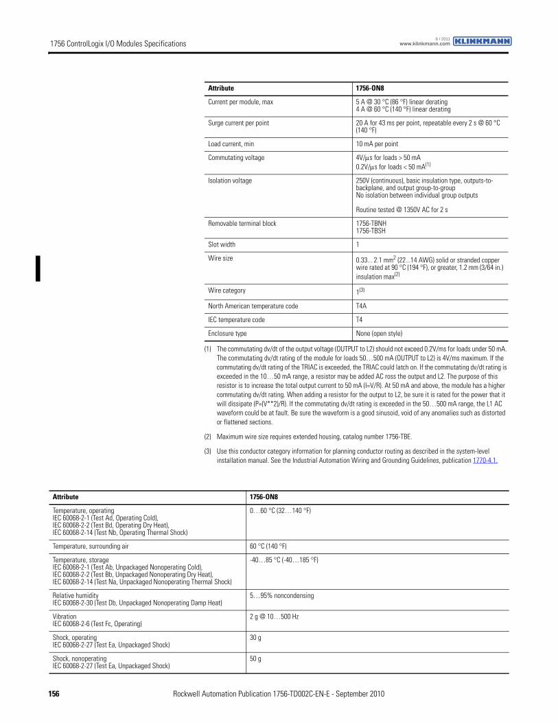
1756 ControlLogix I/O Modules Specifications www.klinkmann.com6 / 2011
Current per module, max 5 A @ 30 °C (86 °F) linear derating4 A @ 60 °C (140 °F) linear derating
Surge current per point 20 A for 43 ms per point, repeatable every 2 s @ 60 °C (140 °F)
Load current, min 10 mA per point
Commutating voltage 4V/μs for loads > 50 mA0.2V/μs for loads < 50 mA(1)
Isolation voltage 250V (continuous), basic insulation type, outputs-to-backplane, and output group-to-groupNo isolation between individual group outputs
Routine tested @ 1350V AC for 2 s
Removable terminal block 1756-TBNH1756-TBSH
Slot width 1
Wire size 0.33... 2.1 mm2 (22...14 AWG) solid or stranded copper wire rated at 90 °C (194 °F), or greater, 1.2 mm (3/64 in.) insulation max(2)
Wire category 1(3)
North American temperature code T4A
IEC temperature code T4
Enclosure type None (open style)
(1) The commutating dv/dt of the output voltage (OUTPUT to L2) should not exceed 0.2V/ms for loads under 50 mA. The commutating dv/dt rating of the module for loads 50…500 mA (OUTPUT to L2) is 4V/ms maximum. If the commutating dv/dt rating of the TRIAC is exceeded, the TRIAC could latch on. If the commutating dv/dt rating is exceeded in the 10…50 mA range, a resistor may be added AC ross the output and L2. The purpose of this resistor is to increase the total output current to 50 mA (I=V/R). At 50 mA and above, the module has a higher commutating dv/dt rating. When adding a resistor for the output to L2, be sure it is rated for the power that it will dissipate (P=(V**2)/R). If the commutating dv/dt rating is exceeded in the 50…500 mA range, the L1 AC waveform could be at fault. Be sure the waveform is a good sinusoid, void of any anomalies such as distorted or flattened sections.
(2) Maximum wire size requires extended housing, catalog number 1756-TBE.
(3) Use this conductor category information for planning conductor routing as described in the system-level installation manual. See the Industrial Automation Wiring and Grounding Guidelines, publication 1770-4.1.
Attribute 1756-ON8
Attribute 1756-ON8
Temperature, operatingIEC 60068-2-1 (Test Ad, Operating Cold),IEC 60068-2-2 (Test Bd, Operating Dry Heat),IEC 60068-2-14 (Test Nb, Operating Thermal Shock)
0…60 °C (32…140 °F)
Temperature, surrounding air 60 °C (140 °F)
Temperature, storageIEC 60068-2-1 (Test Ab, Unpackaged Nonoperating Cold),IEC 60068-2-2 (Test Bb, Unpackaged Nonoperating Dry Heat),IEC 60068-2-14 (Test Na, Unpackaged Nonoperating Thermal Shock)
-40…85 °C (-40…185 °F)
Relative humidityIEC 60068-2-30 (Test Db, Unpackaged Nonoperating Damp Heat)
5…95% noncondensing
VibrationIEC 60068-2-6 (Test Fc, Operating)
2 g @ 10…500 Hz
Shock, operatingIEC 60068-2-27 (Test Ea, Unpackaged Shock)
30 g
Shock, nonoperatingIEC 60068-2-27 (Test Ea, Unpackaged Shock)
50 g
156 Rockwell Automation Publication 1756-TD002C-EN-E - September 2010
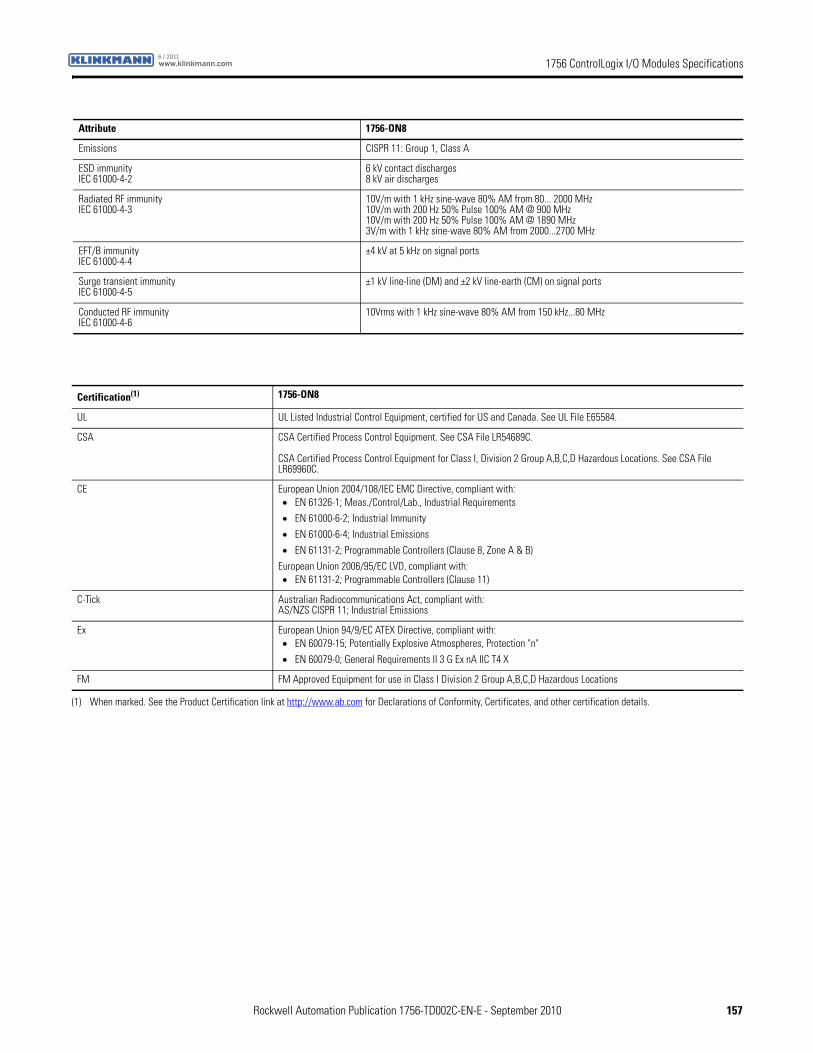
1756 ControlLogix I/O Modules Specificationswww.klinkmann.com6 / 2011
Emissions CISPR 11: Group 1, Class A
ESD immunityIEC 61000-4-2
6 kV contact discharges8 kV air discharges
Radiated RF immunityIEC 61000-4-3
10V/m with 1 kHz sine-wave 80% AM from 80... 2000 MHz10V/m with 200 Hz 50% Pulse 100% AM @ 900 MHz10V/m with 200 Hz 50% Pulse 100% AM @ 1890 MHz3V/m with 1 kHz sine-wave 80% AM from 2000...2700 MHz
EFT/B immunityIEC 61000-4-4
±4 kV at 5 kHz on signal ports
Surge transient immunityIEC 61000-4-5
±1 kV line-line (DM) and ±2 kV line-earth (CM) on signal ports
Conducted RF immunityIEC 61000-4-6
10Vrms with 1 kHz sine-wave 80% AM from 150 kHz...80 MHz
Attribute 1756-ON8
Certification(1) 1756-ON8
UL UL Listed Industrial Control Equipment, certified for US and Canada. See UL File E65584.
CSA CSA Certified Process Control Equipment. See CSA File LR54689C.
CSA Certified Process Control Equipment for Class I, Division 2 Group A,B,C,D Hazardous Locations. See CSA File LR69960C.
CE European Union 2004/108/IEC EMC Directive, compliant with:• EN 61326-1; Meas./Control/Lab., Industrial Requirements
• EN 61000-6-2; Industrial Immunity
• EN 61000-6-4; Industrial Emissions
• EN 61131-2; Programmable Controllers (Clause 8, Zone A & B)
European Union 2006/95/EC LVD, compliant with:• EN 61131-2; Programmable Controllers (Clause 11)
C-Tick Australian Radiocommunications Act, compliant with:AS/NZS CISPR 11; Industrial Emissions
Ex European Union 94/9/EC ATEX Directive, compliant with:• EN 60079-15; Potentially Explosive Atmospheres, Protection "n"
• EN 60079-0; General Requirements II 3 G Ex nA IIC T4 X
FM FM Approved Equipment for use in Class I Division 2 Group A,B,C,D Hazardous Locations
(1) When marked. See the Product Certification link at http://www.ab.com for Declarations of Conformity, Certificates, and other certification details.
Rockwell Automation Publication 1756-TD002C-EN-E - September 2010 157
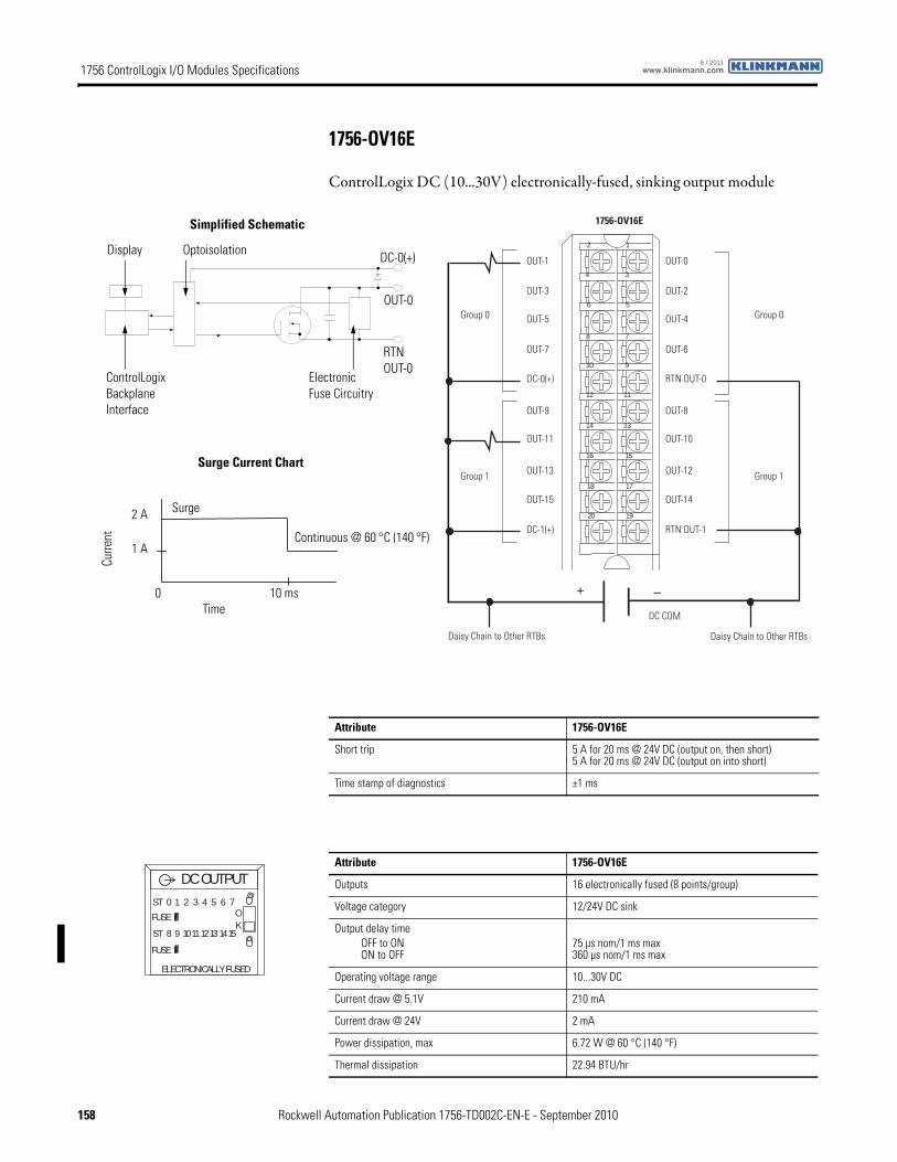
1756 ControlLogix I/O Modules Specifications www.klinkmann.com6 / 2011
1756-OV16E
ControlLogix DC (10...30V) electronically-fused, sinking output module
12
34
56
78
910
1112
1314
1516
1718
1920
+ –
Group 0Group 0
Group 1Group 1
DC COM
1756-OV16E
OUT-1
OUT-3
OUT-5
OUT-7
OUT-9
OUT-11
OUT-13
OUT-15
DC-0(+)
DC-1(+)
OUT-0
OUT-2
OUT-4
OUT-6
OUT-8
OUT-10
OUT-12
OUT-14
RTN OUT-0
RTN OUT-1
Daisy Chain to Other RTBs Daisy Chain to Other RTBs
ControlLogix Backplane Interface
Electronic Fuse Circuitry
Continuous @ 60 °C (140 °F)
Display Optoisolation
RTNOUT-0
OUT-0
DC-0(+)
Surge Current Chart
Simplified Schematic
Surge
Curre
nt
Time0 10 ms
1 A
2 A
Attribute 1756-OV16E
Short trip 5 A for 20 ms @ 24V DC (output on, then short)5 A for 20 ms @ 24V DC (output on into short)
Time stamp of diagnostics ±1 ms
Attribute 1756-OV16E
Outputs 16 electronically fused (8 points/group)
Voltage category 12/24V DC sink
Output delay timeOFF to ONON to OFF
75 µs nom/1 ms max360 µs nom/1 ms max
Operating voltage range 10...30V DC
Current draw @ 5.1V 210 mA
Current draw @ 24V 2 mA
Power dissipation, max 6.72 W @ 60 °C (140 °F)
Thermal dissipation 22.94 BTU/hr
DC OUTPUTST 0 1 2 3 4 5 6 7
ST 8 9 101112131415
OK
FUSE
FUSE
ELECTRONICALLY FUSED
158 Rockwell Automation Publication 1756-TD002C-EN-E - September 2010
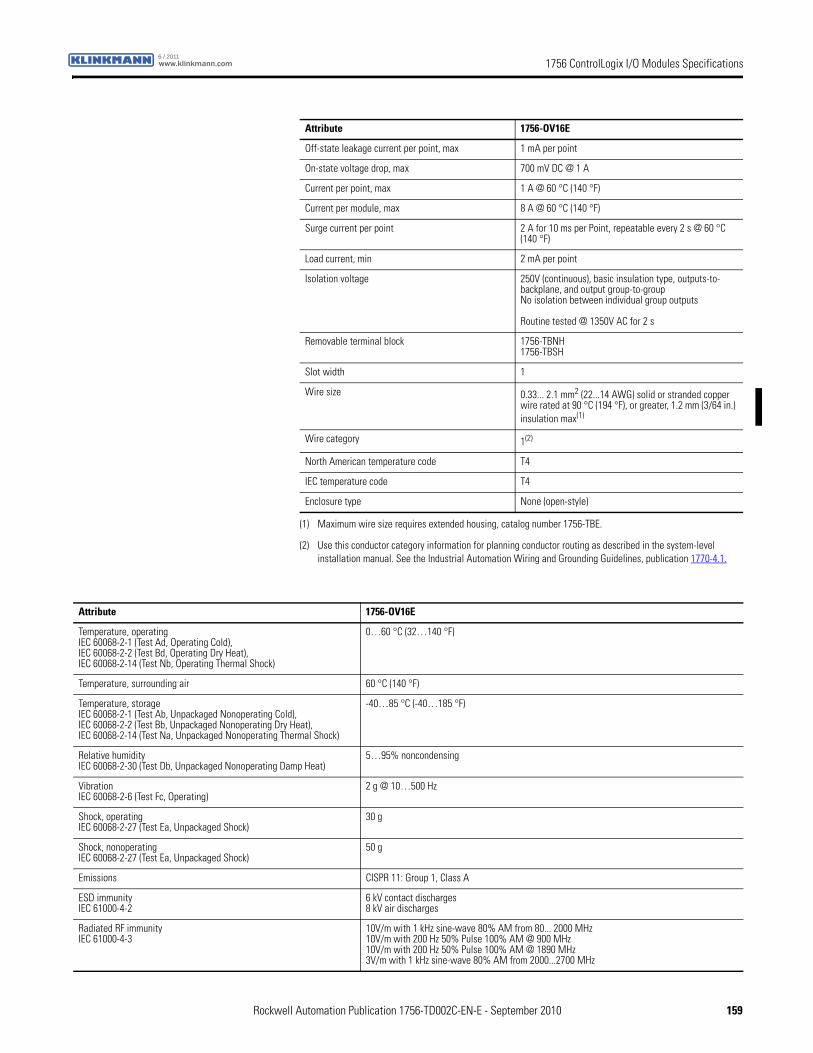
1756 ControlLogix I/O Modules Specificationswww.klinkmann.com6 / 2011
Off-state leakage current per point, max 1 mA per point
On-state voltage drop, max 700 mV DC @ 1 A
Current per point, max 1 A @ 60 °C (140 °F)
Current per module, max 8 A @ 60 °C (140 °F)
Surge current per point 2 A for 10 ms per Point, repeatable every 2 s @ 60 °C (140 °F)
Load current, min 2 mA per point
Isolation voltage 250V (continuous), basic insulation type, outputs-to-backplane, and output group-to-groupNo isolation between individual group outputs
Routine tested @ 1350V AC for 2 s
Removable terminal block 1756-TBNH1756-TBSH
Slot width 1
Wire size 0.33... 2.1 mm2 (22...14 AWG) solid or stranded copper wire rated at 90 °C (194 °F), or greater, 1.2 mm (3/64 in.) insulation max(1)
Wire category 1(2)
North American temperature code T4
IEC temperature code T4
Enclosure type None (open-style)
(1) Maximum wire size requires extended housing, catalog number 1756-TBE.
(2) Use this conductor category information for planning conductor routing as described in the system-level installation manual. See the Industrial Automation Wiring and Grounding Guidelines, publication 1770-4.1.
Attribute 1756-OV16E
Attribute 1756-OV16E
Temperature, operatingIEC 60068-2-1 (Test Ad, Operating Cold),IEC 60068-2-2 (Test Bd, Operating Dry Heat),IEC 60068-2-14 (Test Nb, Operating Thermal Shock)
0…60 °C (32…140 °F)
Temperature, surrounding air 60 °C (140 °F)
Temperature, storageIEC 60068-2-1 (Test Ab, Unpackaged Nonoperating Cold),IEC 60068-2-2 (Test Bb, Unpackaged Nonoperating Dry Heat),IEC 60068-2-14 (Test Na, Unpackaged Nonoperating Thermal Shock)
-40…85 °C (-40…185 °F)
Relative humidityIEC 60068-2-30 (Test Db, Unpackaged Nonoperating Damp Heat)
5…95% noncondensing
VibrationIEC 60068-2-6 (Test Fc, Operating)
2 g @ 10…500 Hz
Shock, operatingIEC 60068-2-27 (Test Ea, Unpackaged Shock)
30 g
Shock, nonoperatingIEC 60068-2-27 (Test Ea, Unpackaged Shock)
50 g
Emissions CISPR 11: Group 1, Class A
ESD immunityIEC 61000-4-2
6 kV contact discharges8 kV air discharges
Radiated RF immunityIEC 61000-4-3
10V/m with 1 kHz sine-wave 80% AM from 80... 2000 MHz10V/m with 200 Hz 50% Pulse 100% AM @ 900 MHz10V/m with 200 Hz 50% Pulse 100% AM @ 1890 MHz3V/m with 1 kHz sine-wave 80% AM from 2000...2700 MHz
Rockwell Automation Publication 1756-TD002C-EN-E - September 2010 159
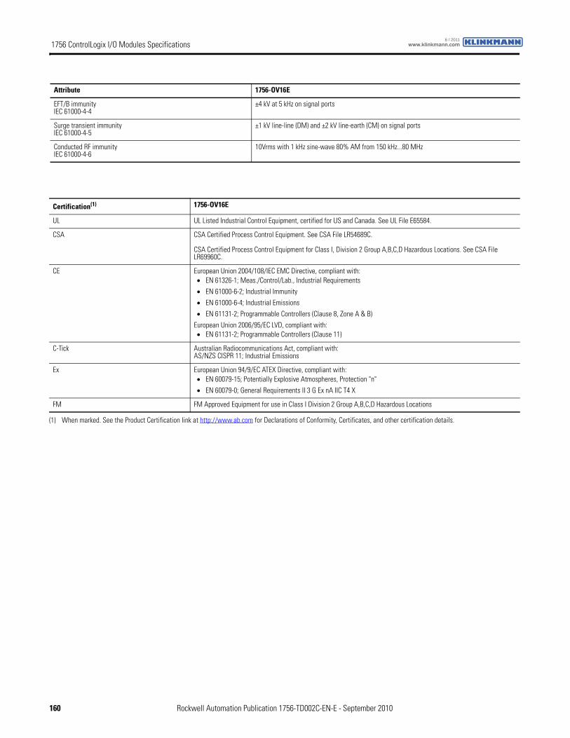
1756 ControlLogix I/O Modules Specifications www.klinkmann.com6 / 2011
EFT/B immunityIEC 61000-4-4
±4 kV at 5 kHz on signal ports
Surge transient immunityIEC 61000-4-5
±1 kV line-line (DM) and ±2 kV line-earth (CM) on signal ports
Conducted RF immunityIEC 61000-4-6
10Vrms with 1 kHz sine-wave 80% AM from 150 kHz...80 MHz
Attribute 1756-OV16E
Certification(1) 1756-OV16E
UL UL Listed Industrial Control Equipment, certified for US and Canada. See UL File E65584.
CSA CSA Certified Process Control Equipment. See CSA File LR54689C.
CSA Certified Process Control Equipment for Class I, Division 2 Group A,B,C,D Hazardous Locations. See CSA File LR69960C.
CE European Union 2004/108/IEC EMC Directive, compliant with:• EN 61326-1; Meas./Control/Lab., Industrial Requirements
• EN 61000-6-2; Industrial Immunity
• EN 61000-6-4; Industrial Emissions
• EN 61131-2; Programmable Controllers (Clause 8, Zone A & B)
European Union 2006/95/EC LVD, compliant with:• EN 61131-2; Programmable Controllers (Clause 11)
C-Tick Australian Radiocommunications Act, compliant with:AS/NZS CISPR 11; Industrial Emissions
Ex European Union 94/9/EC ATEX Directive, compliant with:• EN 60079-15; Potentially Explosive Atmospheres, Protection "n"
• EN 60079-0; General Requirements II 3 G Ex nA IIC T4 X
FM FM Approved Equipment for use in Class I Division 2 Group A,B,C,D Hazardous Locations
(1) When marked. See the Product Certification link at http://www.ab.com for Declarations of Conformity, Certificates, and other certification details.
160 Rockwell Automation Publication 1756-TD002C-EN-E - September 2010
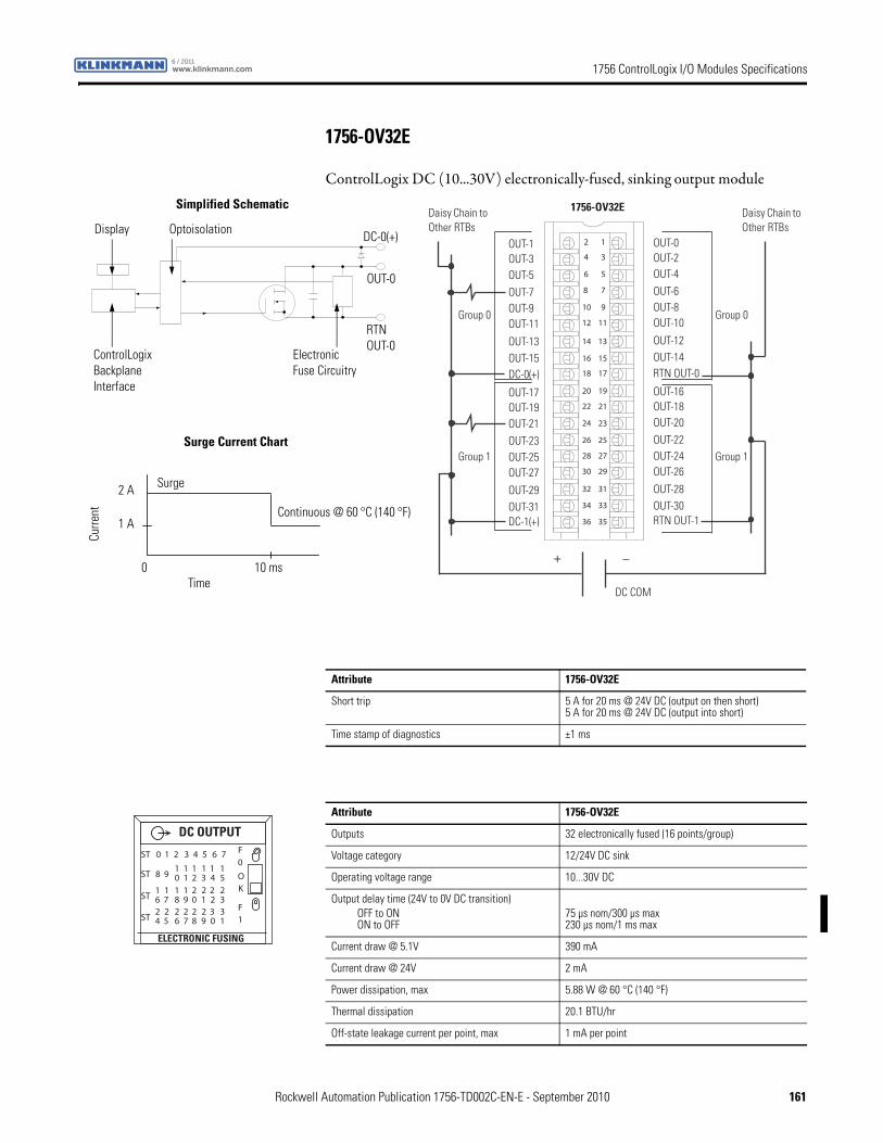
1756 ControlLogix I/O Modules Specificationswww.klinkmann.com6 / 2011
1756-OV32E
ControlLogix DC (10...30V) electronically-fused, sinking output module
12
34
56
78
910
1112
1314
1516
1718
1920
2122
2324
2526
2728
2930
3132
3334
3536
+ _
Daisy Chain to Other RTBs
Daisy Chain to Other RTBs
Group 0
Group 1
Group 0
Group 1
DC COM
OUT-1OUT-3OUT-5OUT-7OUT-9OUT-11
OUT-13OUT-15DC-0(+)
DC-1(+)
OUT-0OUT-2OUT-4OUT-6OUT-8OUT-10
OUT-12OUT-14RTN OUT-0
RTN OUT-1
OUT-17OUT-19OUT-21OUT-23OUT-25OUT-27
OUT-29OUT-31
OUT-16OUT-18OUT-20OUT-22OUT-24OUT-26
OUT-28OUT-30
1756-OV32E
ControlLogix Backplane Interface
Electronic Fuse Circuitry
Continuous @ 60 °C (140 °F)
Display Optoisolation
RTNOUT-0
OUT-0
DC-0(+)
Surge Current Chart
Simplified Schematic
Surge
Curre
nt
Time0 10 ms
1 A
2 A
Attribute 1756-OV32E
Short trip 5 A for 20 ms @ 24V DC (output on then short)5 A for 20 ms @ 24V DC (output into short)
Time stamp of diagnostics ±1 ms
Attribute 1756-OV32E
Outputs 32 electronically fused (16 points/group)
Voltage category 12/24V DC sink
Operating voltage range 10...30V DC
Output delay time (24V to 0V DC transition)OFF to ONON to OFF
75 µs nom/300 µs max230 µs nom/1 ms max
Current draw @ 5.1V 390 mA
Current draw @ 24V 2 mA
Power dissipation, max 5.88 W @ 60 °C (140 °F)
Thermal dissipation 20.1 BTU/hr
Off-state leakage current per point, max 1 mA per point
OK
ST 0 1 2 3 4 5 6 7
ST 8 910 21 3 4 5
1 1 1 11
ST 6 718 09 1 2 3
1 2 2 221 1
ST 4 526 87 9 0 1
2 2 2 332 2
DC OUTPUT
ELECTRONIC FUSING
F0
F1
Rockwell Automation Publication 1756-TD002C-EN-E - September 2010 161
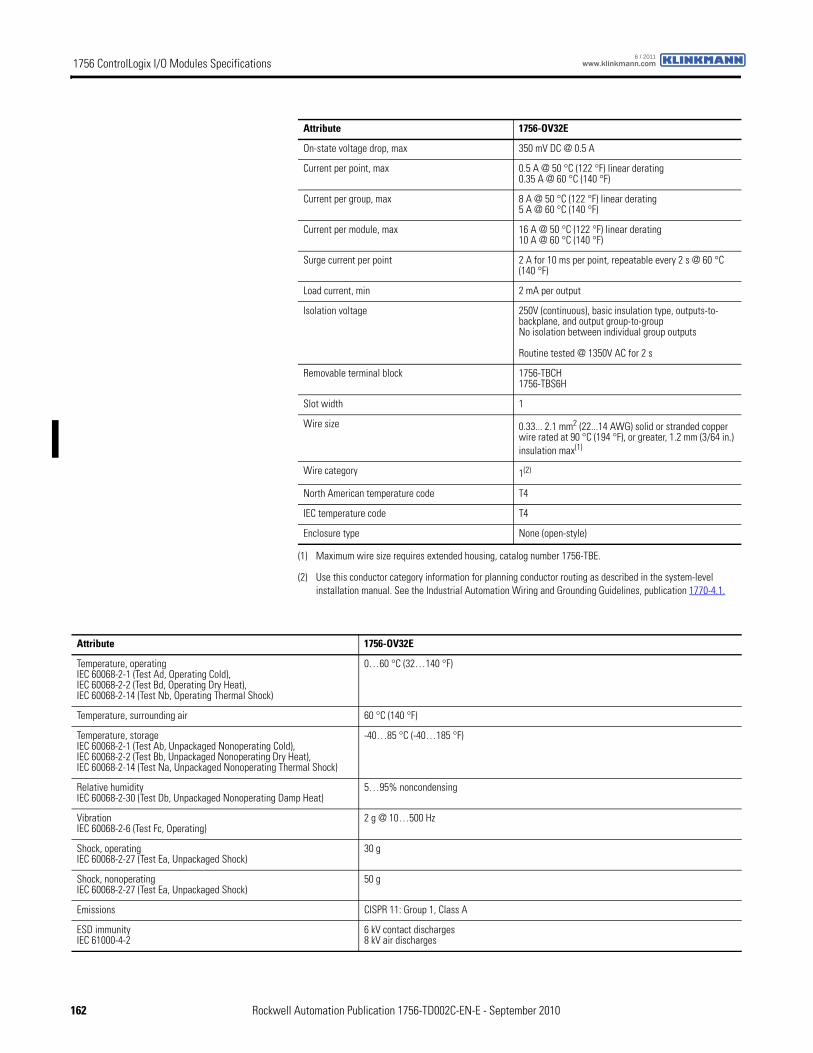
1756 ControlLogix I/O Modules Specifications www.klinkmann.com6 / 2011
On-state voltage drop, max 350 mV DC @ 0.5 A
Current per point, max 0.5 A @ 50 °C (122 °F) linear derating0.35 A @ 60 °C (140 °F)
Current per group, max 8 A @ 50 °C (122 °F) linear derating5 A @ 60 °C (140 °F)
Current per module, max 16 A @ 50 °C (122 °F) linear derating10 A @ 60 °C (140 °F)
Surge current per point 2 A for 10 ms per point, repeatable every 2 s @ 60 °C (140 °F)
Load current, min 2 mA per output
Isolation voltage 250V (continuous), basic insulation type, outputs-to-backplane, and output group-to-groupNo isolation between individual group outputs
Routine tested @ 1350V AC for 2 s
Removable terminal block 1756-TBCH1756-TBS6H
Slot width 1
Wire size 0.33... 2.1 mm2 (22...14 AWG) solid or stranded copper wire rated at 90 °C (194 °F), or greater, 1.2 mm (3/64 in.) insulation max(1)
Wire category 1(2)
North American temperature code T4
IEC temperature code T4
Enclosure type None (open-style)
(1) Maximum wire size requires extended housing, catalog number 1756-TBE.
(2) Use this conductor category information for planning conductor routing as described in the system-level installation manual. See the Industrial Automation Wiring and Grounding Guidelines, publication 1770-4.1.
Attribute 1756-OV32E
Attribute 1756-OV32E
Temperature, operatingIEC 60068-2-1 (Test Ad, Operating Cold),IEC 60068-2-2 (Test Bd, Operating Dry Heat),IEC 60068-2-14 (Test Nb, Operating Thermal Shock)
0…60 °C (32…140 °F)
Temperature, surrounding air 60 °C (140 °F)
Temperature, storageIEC 60068-2-1 (Test Ab, Unpackaged Nonoperating Cold),IEC 60068-2-2 (Test Bb, Unpackaged Nonoperating Dry Heat),IEC 60068-2-14 (Test Na, Unpackaged Nonoperating Thermal Shock)
-40…85 °C (-40…185 °F)
Relative humidityIEC 60068-2-30 (Test Db, Unpackaged Nonoperating Damp Heat)
5…95% noncondensing
VibrationIEC 60068-2-6 (Test Fc, Operating)
2 g @ 10…500 Hz
Shock, operatingIEC 60068-2-27 (Test Ea, Unpackaged Shock)
30 g
Shock, nonoperatingIEC 60068-2-27 (Test Ea, Unpackaged Shock)
50 g
Emissions CISPR 11: Group 1, Class A
ESD immunityIEC 61000-4-2
6 kV contact discharges8 kV air discharges
162 Rockwell Automation Publication 1756-TD002C-EN-E - September 2010
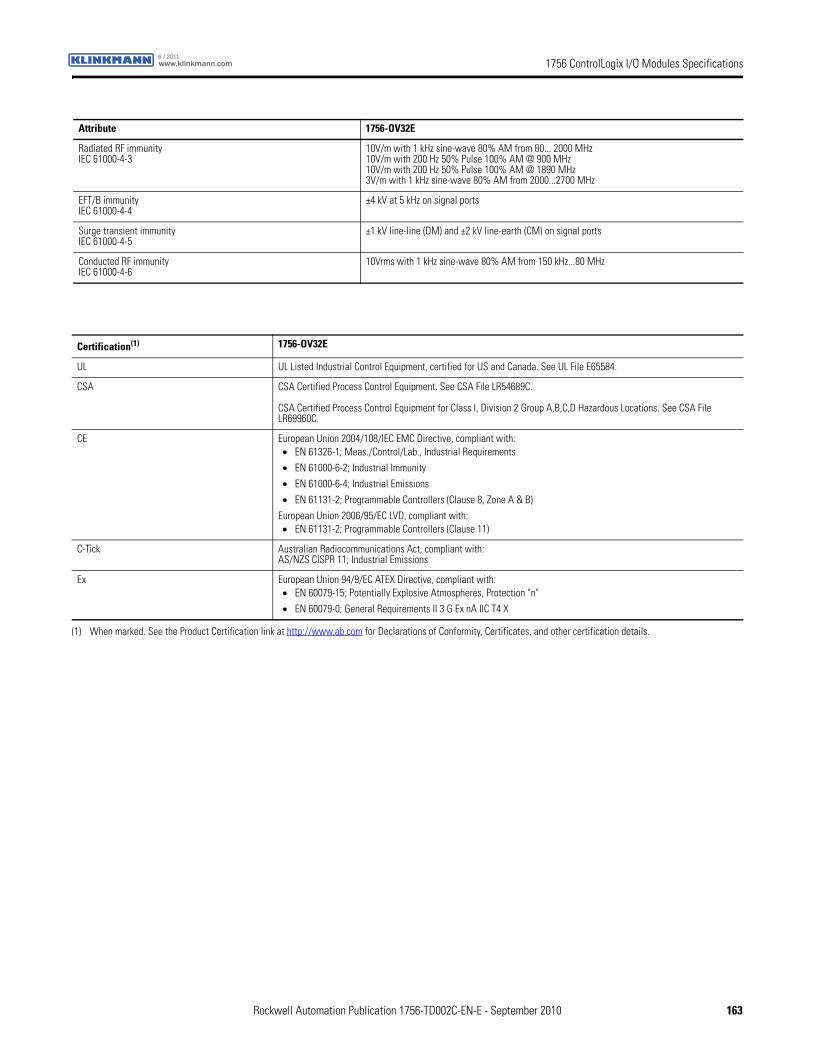
1756 ControlLogix I/O Modules Specificationswww.klinkmann.com6 / 2011
Radiated RF immunityIEC 61000-4-3
10V/m with 1 kHz sine-wave 80% AM from 80... 2000 MHz10V/m with 200 Hz 50% Pulse 100% AM @ 900 MHz10V/m with 200 Hz 50% Pulse 100% AM @ 1890 MHz3V/m with 1 kHz sine-wave 80% AM from 2000...2700 MHz
EFT/B immunityIEC 61000-4-4
±4 kV at 5 kHz on signal ports
Surge transient immunityIEC 61000-4-5
±1 kV line-line (DM) and ±2 kV line-earth (CM) on signal ports
Conducted RF immunityIEC 61000-4-6
10Vrms with 1 kHz sine-wave 80% AM from 150 kHz...80 MHz
Attribute 1756-OV32E
Certification(1) 1756-OV32E
UL UL Listed Industrial Control Equipment, certified for US and Canada. See UL File E65584.
CSA CSA Certified Process Control Equipment. See CSA File LR54689C.
CSA Certified Process Control Equipment for Class I, Division 2 Group A,B,C,D Hazardous Locations. See CSA File LR69960C.
CE European Union 2004/108/IEC EMC Directive, compliant with:• EN 61326-1; Meas./Control/Lab., Industrial Requirements
• EN 61000-6-2; Industrial Immunity
• EN 61000-6-4; Industrial Emissions
• EN 61131-2; Programmable Controllers (Clause 8, Zone A & B)
European Union 2006/95/EC LVD, compliant with:• EN 61131-2; Programmable Controllers (Clause 11)
C-Tick Australian Radiocommunications Act, compliant with:AS/NZS CISPR 11; Industrial Emissions
Ex European Union 94/9/EC ATEX Directive, compliant with:• EN 60079-15; Potentially Explosive Atmospheres, Protection "n"
• EN 60079-0; General Requirements II 3 G Ex nA IIC T4 X
(1) When marked. See the Product Certification link at http://www.ab.com for Declarations of Conformity, Certificates, and other certification details.
Rockwell Automation Publication 1756-TD002C-EN-E - September 2010 163
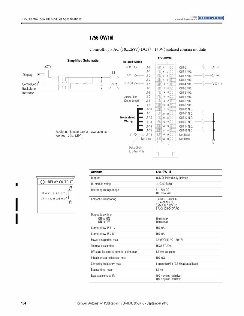
1756 ControlLogix I/O Modules Specifications www.klinkmann.com6 / 2011
1756-OW16I
ControlLogix AC (10...265V) DC (5...150V) isolated contact module
12
34
56
78
910
1112
1314
1516
1718
1920
2122
2324
2526
2728
2930
3132
3334
3536
Nonisolated Wiring
Isolated Wiring
Daisy Chain to Other RTBs
1756-OW16I
L1-0L1-1L1-2L1-3
L1-8
L1-4L1-5L1-6L1-7
L1-9L1-10L1-11L1-12L1-13L1-14L1-15
Not Used
OUT-0 OUT-1 N.O.OUT-2 N.O.OUT-3 N.O.
OUT-8 N.O.
OUT-4 N.O.OUT-5 N.O.OUT-6 N.O.OUT-7 N.O.
Not Used
OUT-9 N.O.OUT-10 N.O.OUT-11 N.O.OUT-12 N.O.OUT-13 N.O.OUT-14 N.O.OUT-15 N.ONot UsedL1
Jumper Bar (Cut to Length)
DC-4 (-)
L2
L1-15
L2-0
DC-4 (+)
L1-0
L1-2 L2-2
ControlLogix Backplane Interface
Display
OUT
L1
+24V
Simplified Schematic
Additional jumper bars are available as cat. no. 1756-JMPR.
Attribute 1756-OW16I
Outputs 16 N.O. individually isolated
UL module rating UL C300 R150
Operating voltage range 5...150V DC10...265V AC
Contact current rating 2 A @ 5…30V DC0.5 A @ 48V DC0.25 A @ 125V DC2 A @ 125/240V AC
Output delay timeOFF to ONON to OFF
10 ms max10 ms max
Current draw @ 5.1V 150 mA
Current draw @ 24V 150 mA
Power dissipation, max 4.5 W @ 60 °C (140 °F)
Thermal dissipation 15.35 BTU/hr
Off-state leakage current per point, max 1.5 mA per point
Initial contact resistance, max 100 mΩ
Switching frequency, max 1 operation/3 s (0.3 Hz at rated load)
Bounce time, mean 1.2 ms
Expected contact life 300 K cycles resistive100 K cycles inductive
ST 0 1 2 3 4 5 6 7
ST 8 9 10 11 12 13 14 15
OK
RELAY OUTPUT
164 Rockwell Automation Publication 1756-TD002C-EN-E - September 2010
1756 ControlLogix I/O Modules Specificationswww.klinkmann.com6 / 2011
Isolation voltage 250V (continuous), basic insulation type, outputs-to-backplane, and output-to-output
Routine tested @ 1350V AC for 2 s
Removable terminal block 1756-TBCH1756-TBS6H
Slot width 1
Wire size 0.33... 2.1 mm2 (22...14 AWG) solid or stranded copper wire rated at 90 °C (194 °F), or greater, 1.2 mm (3/64 in.) insulation max(1)
Wire category 1(2)
North American temperature code T4A
Enclosure type None (open-style)
(1) Maximum wire size requires extended housing, catalog number 1756-TBE.
(2) Use this conductor category information for planning conductor routing as described in the system-level installation manual. See the Industrial Automation Wiring and Grounding Guidelines, publication 1770-4.1.
Attribute 1756-OW16I
Attribute 1756-OW16I
Temperature, operatingIEC 60068-2-1 (Test Ad, Operating Cold),IEC 60068-2-2 (Test Bd, Operating Dry Heat),IEC 60068-2-14 (Test Nb, Operating Thermal Shock)
0…60 °C (32…140 °F)
Temperature, surrounding air 60 °C (140 °F)
Temperature, storageIEC 60068-2-1 (Test Ab, Unpackaged Nonoperating Cold),IEC 60068-2-2 (Test Bb, Unpackaged Nonoperating Dry Heat),IEC 60068-2-14 (Test Na, Unpackaged Nonoperating Thermal Shock)
-40…85 °C (-40…185 °F)
Relative humidityIEC 60068-2-30 (Test Db, Unpackaged Nonoperating Damp Heat)
5…95% noncondensing
VibrationIEC 60068-2-6 (Test Fc, Operating)
2 g @ 10…500 Hz
Shock, operatingIEC 60068-2-27 (Test Ea, Unpackaged Shock)
30 g
Shock, nonoperatingIEC 60068-2-27 (Test Ea, Unpackaged Shock)
50 g
Emissions CISPR 11: Group 1, Class A
ESD immunityIEC 61000-4-2
6 kV contact discharges8 kV air discharges
Radiated RF immunityIEC 61000-4-3
10V/m with 1 kHz sine-wave 80% AM from 80... 2000 MHz10V/m with 200 Hz 50% Pulse 100% AM @ 900 MHz10V/m with 200 Hz 50% Pulse 100% AM @ 1890 MHz3V/m with 1 kHz sine-wave 80% AM from 2000...2700 MHz
EFT/B immunityIEC 61000-4-4
±4 kV at 5 kHz on signal ports
Surge transient immunityIEC 61000-4-5
±1 kV line-line (DM) and ±2 kV line-earth (CM) on signal ports
Conducted RF immunityIEC 61000-4-6
10Vrms with 1 kHz sine-wave 80% AM from 150 kHz...80 MHz
Oscillatory surge withstandIEEE C37.90.1
3 kV
Rockwell Automation Publication 1756-TD002C-EN-E - September 2010 165
1756 ControlLogix I/O Modules Specifications www.klinkmann.com6 / 2011
Certification(1) 1756-OW16I
UL UL Listed Industrial Control Equipment, certified for US and Canada. See UL File E65584.
CSA CSA Certified Process Control Equipment. See CSA File LR54689C.
CSA Certified Process Control Equipment for Class I, Division 2 Group A,B,C,D Hazardous Locations. See CSA File LR69960C.
CE European Union 2004/108/IEC EMC Directive, compliant with:• EN 61326-1; Meas./Control/Lab., Industrial Requirements
• EN 61000-6-2; Industrial Immunity
• EN 61000-6-4; Industrial Emissions
• EN 61131-2; Programmable Controllers (Clause 8, Zone A & B)
European Union 2006/95/EC LVD, compliant with:• EN 61131-2; Programmable Controllers
C-Tick Australian Radiocommunications Act, compliant with:AS/NZS CISPR 11; Industrial Emissions
FM FM Approved Equipment for use in Class I Division 2 Group A,B,C,D Hazardous Locations
TÜV TÜV Certified for Functional Safety:Capable of SIL 2
(1) When marked. See the Product Certification link at http://www.ab.com for Declarations of Conformity, Certificates, and other certification details.
166 Rockwell Automation Publication 1756-TD002C-EN-E - September 2010
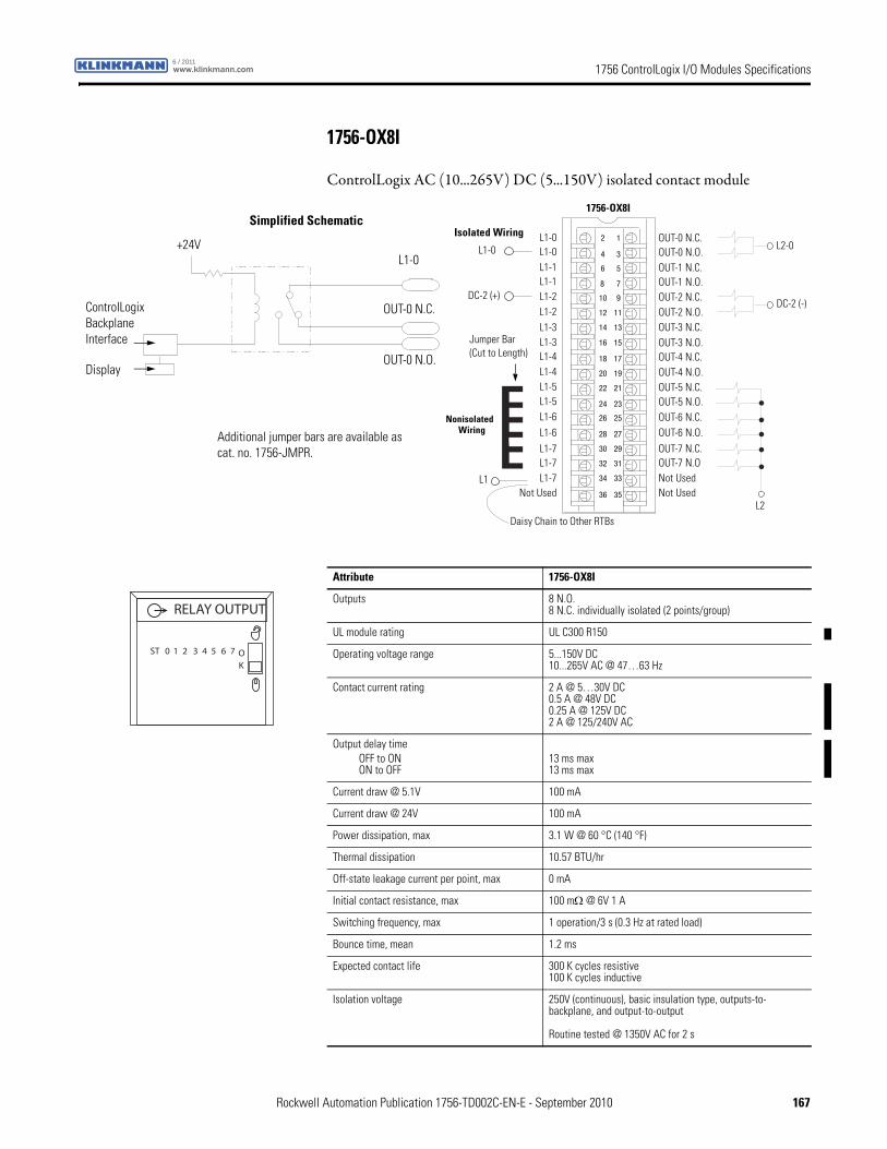
1756 ControlLogix I/O Modules Specificationswww.klinkmann.com6 / 2011
1756-OX8I
ControlLogix AC (10...265V) DC (5...150V) isolated contact module
12
34
56
78
910
1112
1314
1516
1718
1920
2122
2324
2526
2728
2930
3132
3334
3536
Nonisolated Wiring
Isolated Wiring
Daisy Chain to Other RTBs
1756-OX8I
L1-0L1-0L1-1L1-1
L1-4
L1-2L1-2L1-3L1-3
L1-4L1-5L1-5L1-6L1-6L1-7L1-7
Not Used
OUT-0 N.C.OUT-0 N.O.OUT-1 N.C.OUT-1 N.O.
OUT-4 N.C.
OUT-2 N.C.OUT-2 N.O.OUT-3 N.C.OUT-3 N.O.
Not Used
OUT-4 N.O.OUT-5 N.C.OUT-5 N.O.OUT-6 N.C.OUT-6 N.O.OUT-7 N.C.OUT-7 N.ONot UsedL1
DC-2 (-)
L2
L1-7
L2-0
DC-2 (+)
L1-0
Jumper Bar (Cut to Length)
ControlLogix Backplane Interface
+24V
Display
L1-0
OUT-0 N.C.
OUT-0 N.O.
Simplified Schematic
Additional jumper bars are available as cat. no. 1756-JMPR.
Attribute 1756-OX8I
Outputs 8 N.O.8 N.C. individually isolated (2 points/group)
UL module rating UL C300 R150
Operating voltage range 5...150V DC10...265V AC @ 47…63 Hz
Contact current rating 2 A @ 5…30V DC0.5 A @ 48V DC0.25 A @ 125V DC2 A @ 125/240V AC
Output delay timeOFF to ONON to OFF
13 ms max13 ms max
Current draw @ 5.1V 100 mA
Current draw @ 24V 100 mA
Power dissipation, max 3.1 W @ 60 °C (140 °F)
Thermal dissipation 10.57 BTU/hr
Off-state leakage current per point, max 0 mA
Initial contact resistance, max 100 mΩ @ 6V 1 A
Switching frequency, max 1 operation/3 s (0.3 Hz at rated load)
Bounce time, mean 1.2 ms
Expected contact life 300 K cycles resistive100 K cycles inductive
Isolation voltage 250V (continuous), basic insulation type, outputs-to-backplane, and output-to-output
Routine tested @ 1350V AC for 2 s
ST 0 1 2 3 4 5 6 7 OK
RELAY OUTPUT
Rockwell Automation Publication 1756-TD002C-EN-E - September 2010 167
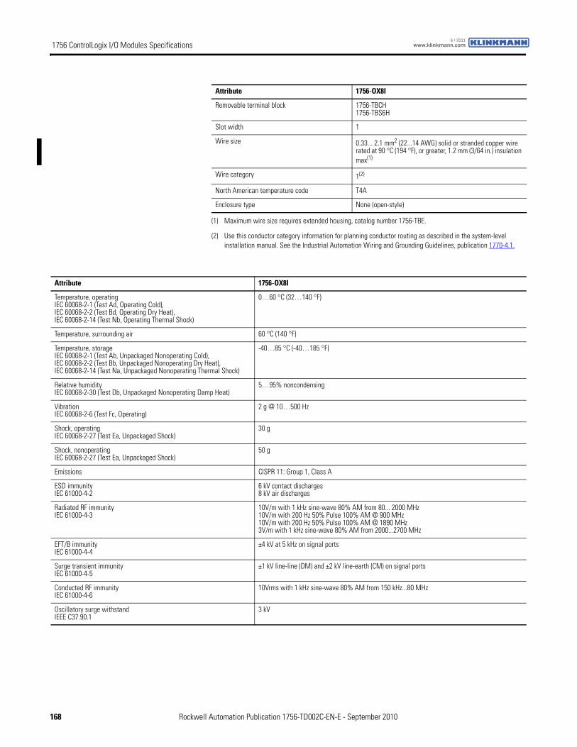
1756 ControlLogix I/O Modules Specifications www.klinkmann.com6 / 2011
Removable terminal block 1756-TBCH1756-TBS6H
Slot width 1
Wire size 0.33... 2.1 mm2 (22...14 AWG) solid or stranded copper wire rated at 90 °C (194 °F), or greater, 1.2 mm (3/64 in.) insulation max(1)
Wire category 1(2)
North American temperature code T4A
Enclosure type None (open-style)
(1) Maximum wire size requires extended housing, catalog number 1756-TBE.
(2) Use this conductor category information for planning conductor routing as described in the system-level installation manual. See the Industrial Automation Wiring and Grounding Guidelines, publication 1770-4.1.
Attribute 1756-OX8I
Attribute 1756-OX8I
Temperature, operatingIEC 60068-2-1 (Test Ad, Operating Cold),IEC 60068-2-2 (Test Bd, Operating Dry Heat),IEC 60068-2-14 (Test Nb, Operating Thermal Shock)
0…60 °C (32…140 °F)
Temperature, surrounding air 60 °C (140 °F)
Temperature, storageIEC 60068-2-1 (Test Ab, Unpackaged Nonoperating Cold),IEC 60068-2-2 (Test Bb, Unpackaged Nonoperating Dry Heat),IEC 60068-2-14 (Test Na, Unpackaged Nonoperating Thermal Shock)
-40…85 °C (-40…185 °F)
Relative humidityIEC 60068-2-30 (Test Db, Unpackaged Nonoperating Damp Heat)
5…95% noncondensing
VibrationIEC 60068-2-6 (Test Fc, Operating)
2 g @ 10…500 Hz
Shock, operatingIEC 60068-2-27 (Test Ea, Unpackaged Shock)
30 g
Shock, nonoperatingIEC 60068-2-27 (Test Ea, Unpackaged Shock)
50 g
Emissions CISPR 11: Group 1, Class A
ESD immunityIEC 61000-4-2
6 kV contact discharges8 kV air discharges
Radiated RF immunityIEC 61000-4-3
10V/m with 1 kHz sine-wave 80% AM from 80... 2000 MHz10V/m with 200 Hz 50% Pulse 100% AM @ 900 MHz10V/m with 200 Hz 50% Pulse 100% AM @ 1890 MHz3V/m with 1 kHz sine-wave 80% AM from 2000...2700 MHz
EFT/B immunityIEC 61000-4-4
±4 kV at 5 kHz on signal ports
Surge transient immunityIEC 61000-4-5
±1 kV line-line (DM) and ±2 kV line-earth (CM) on signal ports
Conducted RF immunityIEC 61000-4-6
10Vrms with 1 kHz sine-wave 80% AM from 150 kHz...80 MHz
Oscillatory surge withstandIEEE C37.90.1
3 kV
168 Rockwell Automation Publication 1756-TD002C-EN-E - September 2010
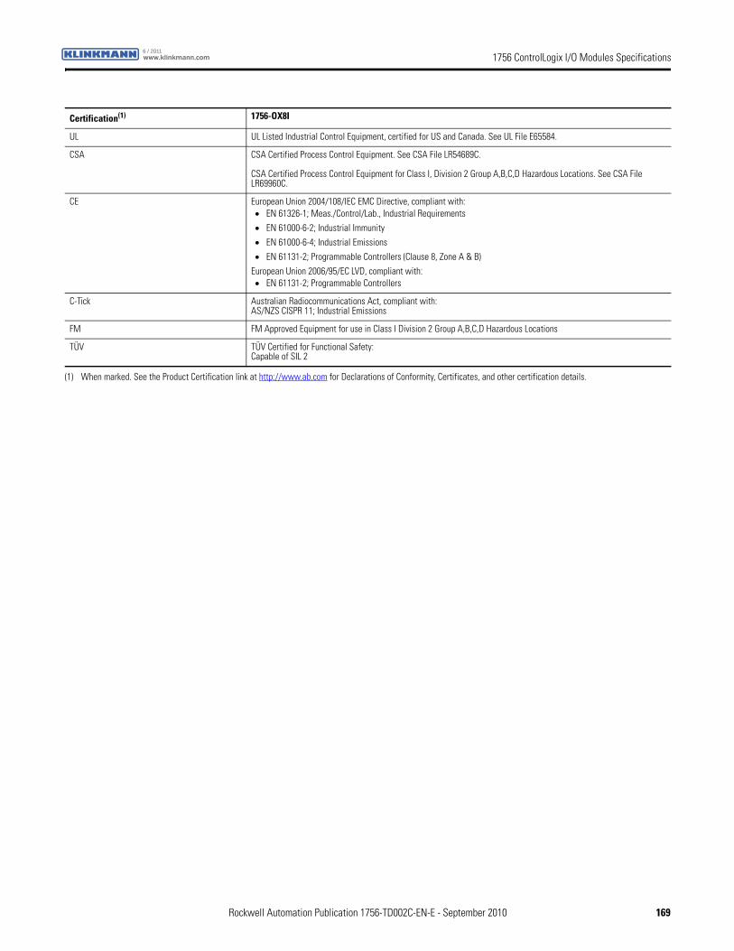
1756 ControlLogix I/O Modules Specificationswww.klinkmann.com6 / 2011
Certification(1) 1756-OX8I
UL UL Listed Industrial Control Equipment, certified for US and Canada. See UL File E65584.
CSA CSA Certified Process Control Equipment. See CSA File LR54689C.
CSA Certified Process Control Equipment for Class I, Division 2 Group A,B,C,D Hazardous Locations. See CSA File LR69960C.
CE European Union 2004/108/IEC EMC Directive, compliant with:• EN 61326-1; Meas./Control/Lab., Industrial Requirements
• EN 61000-6-2; Industrial Immunity
• EN 61000-6-4; Industrial Emissions
• EN 61131-2; Programmable Controllers (Clause 8, Zone A & B)
European Union 2006/95/EC LVD, compliant with:• EN 61131-2; Programmable Controllers
C-Tick Australian Radiocommunications Act, compliant with:AS/NZS CISPR 11; Industrial Emissions
FM FM Approved Equipment for use in Class I Division 2 Group A,B,C,D Hazardous Locations
TÜV TÜV Certified for Functional Safety:Capable of SIL 2
(1) When marked. See the Product Certification link at http://www.ab.com for Declarations of Conformity, Certificates, and other certification details.
Rockwell Automation Publication 1756-TD002C-EN-E - September 2010 169
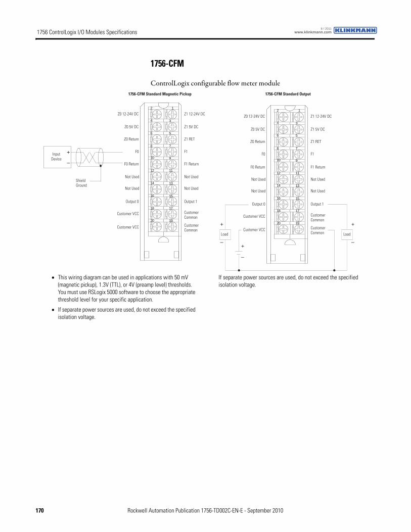
1756 ControlLogix I/O Modules Specifications www.klinkmann.com6 / 2011
1756-CFM
ControlLogix configurable flow meter module
Shield Ground
Input Device
1756-CFM Standard Magnetic Pickup
Z0 12-24V DC
Z0 5V DC
Z0 Return
Customer VCC
F0
F0 Return
Not Used
Not Used
Output 0
Customer VCC
Z1 12-24V DC
Z1 5V DC
Z1 RET
Not Used
Customer Common
Not Used
Output 1
F1
F1 Return
12
34
56
78
910
1112
1314
1516
1718
1920Customer Common
+
–
1756-CFM Standard Output
12
34
56
78
910
1112
1314
1516
1718
1920
Load
+
–
Z0 12-24V DC
Z0 5V DC
Z0 Return
Customer VCC
F0
F0 Return
Not Used
Not Used
Output 0
Customer VCC
Z1 12-24V DC
Z1 5V DC
Z1 RET
Not Used
Customer Common
Not Used
Output 1
F1
F1 Return
Customer Common Load
+
–+
–
• This wiring diagram can be used in applications with 50 mV (magnetic pickup), 1.3V (TTL), or 4V (preamp level) thresholds. You must use RSLogix 5000 software to choose the appropriate threshold level for your specific application.
• If separate power sources are used, do not exceed the specified isolation voltage.
If separate power sources are used, do not exceed the specified isolation voltage.
170 Rockwell Automation Publication 1756-TD002C-EN-E - September 2010
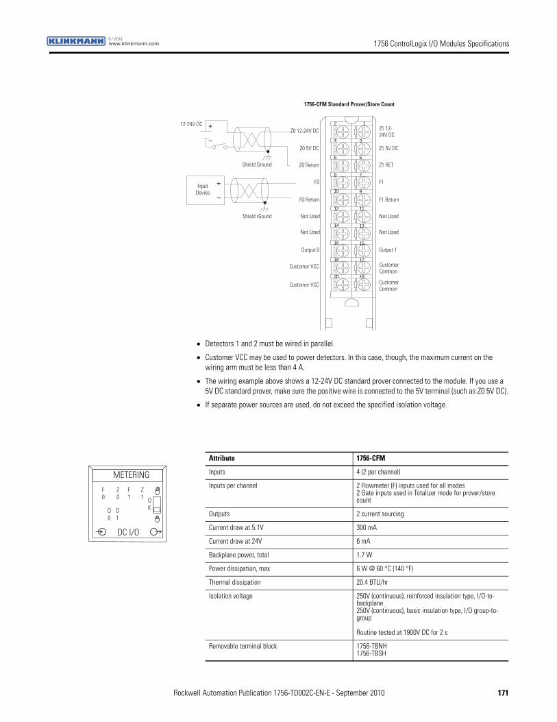
1756 ControlLogix I/O Modules Specificationswww.klinkmann.com6 / 2011
Shield rGound
Input Device
1756-CFM Standard Prover/Store Count
12
34
56
78
910
1112
1314
1516
1718
1920
+
–
Z0 12-24V DC
Z0 5V DC
Z0 Return
Customer VCC
F0
F0 Return
Not Used
Not Used
Output 0
Customer VCC
Z1 12- 24V DC
Z1 5V DC
Z1 RET
Not Used
Customer Common
Not Used
Output 1
F1
F1 Return
Customer Common
12-24V DC +
–
Shield Ground
• Detectors 1 and 2 must be wired in parallel.
• Customer VCC may be used to power detectors. In this case, though, the maximum current on the wiring arm must be less than 4 A.
• The wiring example above shows a 12-24V DC standard prover connected to the module. If you use a 5V DC standard prover, make sure the positive wire is connected to the 5V terminal (such as Z0 5V DC).
• If separate power sources are used, do not exceed the specified isolation voltage.
Attribute 1756-CFM
Inputs 4 (2 per channel)
Inputs per channel 2 Flowmeter (F) inputs used for all modes2 Gate inputs used in Totalizer mode for prover/store count
Outputs 2 current sourcing
Current draw at 5.1V 300 mA
Current draw at 24V 6 mA
Backplane power, total 1.7 W
Power dissipation, max 6 W @ 60 °C (140 °F)
Thermal dissipation 20.4 BTU/hr
Isolation voltage 250V (continuous), reinforced insulation type, I/O-to-backplane250V (continuous), basic insulation type, I/O group-to-group
Routine tested at 1900V DC for 2 s
Removable terminal block 1756-TBNH1756-TBSH
METERING
DC I/O
OK
F0
Z0
F1
Z1
O0
O1
Rockwell Automation Publication 1756-TD002C-EN-E - September 2010 171
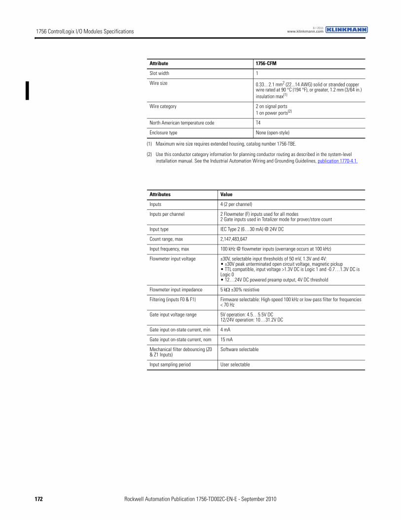
1756 ControlLogix I/O Modules Specifications www.klinkmann.com6 / 2011
Slot width 1
Wire size 0.33... 2.1 mm2 (22...14 AWG) solid or stranded copper wire rated at 90 °C (194 °F), or greater, 1.2 mm (3/64 in.) insulation max(1)
Wire category 2 on signal ports1 on power ports(2)
North American temperature code T4
Enclosure type None (open-style)
(1) Maximum wire size requires extended housing, catalog number 1756-TBE.
(2) Use this conductor category information for planning conductor routing as described in the system-level installation manual. See the Industrial Automation Wiring and Grounding Guidelines, publication 1770-4.1.
Attributes Value
Inputs 4 (2 per channel)
Inputs per channel 2 Flowmeter (F) inputs used for all modes2 Gate inputs used in Totalizer mode for prover/store count
Input type IEC Type 2 (6…30 mA) @ 24V DC
Count range, max 2,147,483,647
Input frequency, max 100 kHz @ flowmeter inputs (overrange occurs at 100 kHz)
Flowmeter input voltage ±30V, selectable input thresholds of 50 mV, 1.3V and 4V:• ±30V peak unterminated open circuit voltage, magnetic pickup• TTL compatible, input voltage >1.3V DC is Logic 1 and -0.7…1.3V DC is Logic 0• 12…24V DC powered preamp output, 4V DC threshold
Flowmeter input impedance 5 kΩ ±30% resistive
Filtering (inputs F0 & F1) Firmware selectable: High-speed 100 kHz or low-pass filter for frequencies < 70 Hz
Gate input voltage range 5V operation: 4.5…5.5V DC12/24V operation: 10…31.2V DC
Gate input on-state current, min 4 mA
Gate input on-state current, nom 15 mA
Mechanical filter debouncing (Z0 & Z1 Inputs)
Software selectable
Input sampling period User selectable
Attribute 1756-CFM
172 Rockwell Automation Publication 1756-TD002C-EN-E - September 2010
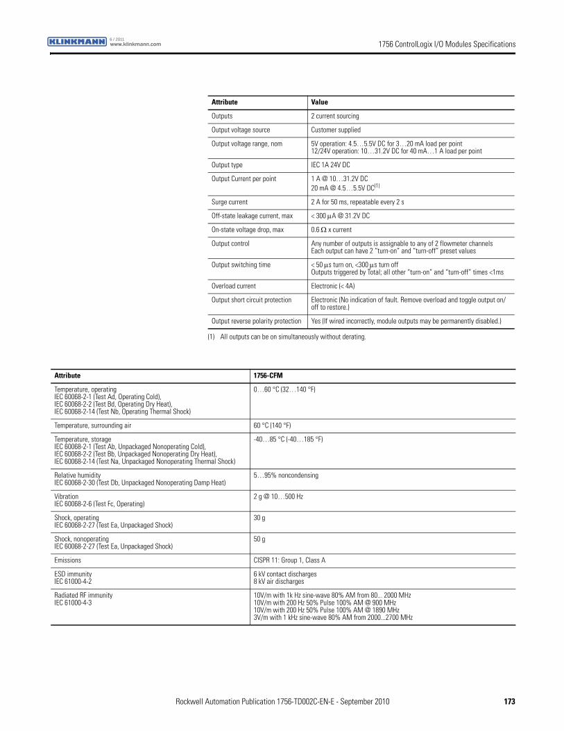
1756 ControlLogix I/O Modules Specificationswww.klinkmann.com6 / 2011
Attribute Value
Outputs 2 current sourcing
Output voltage source Customer supplied
Output voltage range, nom 5V operation: 4.5…5.5V DC for 3…20 mA load per point12/24V operation: 10…31.2V DC for 40 mA…1 A load per point
Output type IEC 1A 24V DC
Output Current per point 1 A @ 10…31.2V DC20 mA @ 4.5…5.5V DC(1)
(1) All outputs can be on simultaneously without derating.
Surge current 2 A for 50 ms, repeatable every 2 s
Off-state leakage current, max < 300 μA @ 31.2V DC
On-state voltage drop, max 0.6 Ω x current
Output control Any number of outputs is assignable to any of 2 flowmeter channelsEach output can have 2 “turn-on” and “turn-off” preset values
Output switching time < 50 μs turn on, <300 μs turn offOutputs triggered by Total; all other “turn-on” and “turn-off” times <1ms
Overload current Electronic (< 4A)
Output short circuit protection Electronic (No indication of fault. Remove overload and toggle output on/off to restore.)
Output reverse polarity protection Yes (If wired incorrectly, module outputs may be permanently disabled.)
Attribute 1756-CFM
Temperature, operatingIEC 60068-2-1 (Test Ad, Operating Cold),IEC 60068-2-2 (Test Bd, Operating Dry Heat),IEC 60068-2-14 (Test Nb, Operating Thermal Shock)
0…60 °C (32…140 °F)
Temperature, surrounding air 60 °C (140 °F)
Temperature, storageIEC 60068-2-1 (Test Ab, Unpackaged Nonoperating Cold),IEC 60068-2-2 (Test Bb, Unpackaged Nonoperating Dry Heat),IEC 60068-2-14 (Test Na, Unpackaged Nonoperating Thermal Shock)
-40…85 °C (-40…185 °F)
Relative humidityIEC 60068-2-30 (Test Db, Unpackaged Nonoperating Damp Heat)
5…95% noncondensing
VibrationIEC 60068-2-6 (Test Fc, Operating)
2 g @ 10…500 Hz
Shock, operatingIEC 60068-2-27 (Test Ea, Unpackaged Shock)
30 g
Shock, nonoperatingIEC 60068-2-27 (Test Ea, Unpackaged Shock)
50 g
Emissions CISPR 11: Group 1, Class A
ESD immunityIEC 61000-4-2
6 kV contact discharges8 kV air discharges
Radiated RF immunityIEC 61000-4-3
10V/m with 1k Hz sine-wave 80% AM from 80... 2000 MHz10V/m with 200 Hz 50% Pulse 100% AM @ 900 MHz10V/m with 200 Hz 50% Pulse 100% AM @ 1890 MHz3V/m with 1 kHz sine-wave 80% AM from 2000...2700 MHz
Rockwell Automation Publication 1756-TD002C-EN-E - September 2010 173
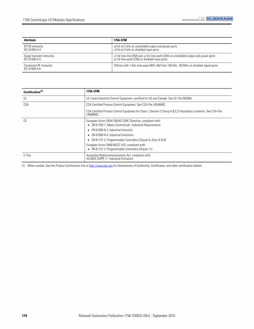
1756 ControlLogix I/O Modules Specifications www.klinkmann.com6 / 2011
EFT/B immunityIEC 61000-4-4
±4 kV at 5 kHz on unshielded output and power ports±4 kV at 5 kHz on shielded input ports
Surge transient immunityIEC 61000-4-5
±1 kV line-line (DM) and ±2 kV line-earth (CM) on unshielded output and power ports±2 kV line-earth (CM) on shielded input ports
Conducted RF immunityIEC 61000-4-6
10Vrms with 1 kHz sine-wave 80% AM from 150 kHz...80 MHz on shielded signal ports
Attribute 1756-CFM
Certification(1) 1756-CFM
UL UL Listed Industrial Control Equipment, certified for US and Canada. See UL File E65584.
CSA CSA Certified Process Control Equipment. See CSA File LR54689C.
CSA Certified Process Control Equipment for Class I, Division 2 Group A,B,C,D Hazardous Locations. See CSA File LR69960C.
CE European Union 2004/108/IEC EMC Directive, compliant with:• EN 61326-1; Meas./Control/Lab., Industrial Requirements
• EN 61000-6-2; Industrial Immunity
• EN 61000-6-4; Industrial Emissions
• EN 61131-2; Programmable Controllers (Clause 8, Zone A & B)
European Union 2006/95/EC LVD, compliant with:• EN 61131-2; Programmable Controllers (Clause 11)
C-Tick Australian Radiocommunications Act, compliant with:AS/NZS CISPR 11; Industrial Emissions
(1) When marked. See the Product Certification link at http://www.ab.com for Declarations of Conformity, Certificates, and other certification details.
174 Rockwell Automation Publication 1756-TD002C-EN-E - September 2010
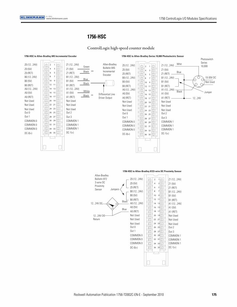
1756 ControlLogix I/O Modules Specificationswww.klinkmann.com6 / 2011
1756-HSC
ControlLogix high-speed counter module
12
34
56
78
910
1112
1314
1516
1718
1920
2122
2324
2526
2728
2930
3132
3334
3536
Z1 (12...24V)
Z1 (5V)Z1 (RET)B1 (12...24V)B1 (5V)
B1 (RET)A1 (12...24V)A1 (5V)
A1 (RET)Not UsedNot Used
Not Used
Z0 (12...24V)
Z0 (5V)Z0 (RET)B0 (12..24V)B0 (5V)
B0 (RET)A0 (12...24V)A0 (5V)
A0 (RET)Not UsedNot Used
Not Used
COMMON 0COMMON 0COMMON 0
DC-0(+)
Out 2
Out 3COMMON 1COMMON 1COMMON 1DC-1(+)
Out 0Out 1
Black
Black
White
Black
Blue
GreenAllen-Bradley Bulletin 845 IncrementalEncoder
Differential Line Driver Output
1756-HSC to Allen-Bradley 845 Incremental Encoder
12
34
56
78
910
1112
1314
1516
1718
1920
2122
2324
2526
2728
2930
3132
3334
3536
JumperBlack
Blue
Whit
Not Used
10-30V DC
Photoswitch Series 10,000 Z1 (12...24V)
Z1 (5V)Z1 (RET)B1 (12...24V)B1 (5V)
B1 (RET)A1 (12...24V)A1 (5V)
A1 (RET)Not UsedNot Used
Not Used
Z0 (12...24V)
Z0 (5V)Z0 (RET)B0 (12...24V)B0 (5V)
B0 (RET)A0 (12...24V)A0 (5V)
A0 (RET)Not UsedNot Used
Not Used
COMMON 0COMMON 0COMMON 0
DC-0(+)
Out 2
Out 3COMMON 1COMMON 1COMMON 1DC-1(+)
Out 0Out 1
12...24V
1756-HSC to Allen-Bradley Series 10,000 Photoelectric Sensor
12
34
56
78
910
1112
1314
1516
1718
1920
2122
2324
2526
2728
2930
3132
3334
3536
Jumpers
Black
Blue
Allen-Bradley Bulletin 872 3-wire DC ProximitySensor
Z1 (12...24V)
Z1 (5V)Z1 (RET)B1 (12...24V)B1 (5V)
B1 (RET)A1 (12...24V)A1 (5V)
A1 (RET)Not UsedNot Used
Not Used
Z0 (12...24V)
Z0 (5V)Z0 (RET)B0 (12...24V)B0 (5V)
B0 (RET)A0 (12...24V)A0 (5V)
A0 (RET)Not UsedNot Used
Not Used
COMMON 0COMMON 0COMMON 0
DC-0(+)
Out 2
Out 3COMMON 1COMMON 1COMMON 1DC-1(+)
Out 0Out 1
12...24V DC Return
12...24V DC
1756-HSC to Allen-Bradley 8723-wire DC Proximity Sensor
Rockwell Automation Publication 1756-TD002C-EN-E - September 2010 175
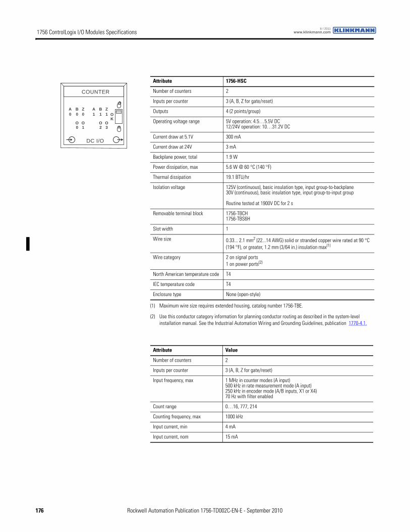
1756 ControlLogix I/O Modules Specifications www.klinkmann.com6 / 2011
Attribute 1756-HSC
Number of counters 2
Inputs per counter 3 (A, B, Z for gate/reset)
Outputs 4 (2 points/group)
Operating voltage range 5V operation: 4.5…5.5V DC12/24V operation: 10…31.2V DC
Current draw at 5.1V 300 mA
Current draw at 24V 3 mA
Backplane power, total 1.9 W
Power dissipation, max 5.6 W @ 60 °C (140 °F)
Thermal dissipation 19.1 BTU/hr
Isolation voltage 125V (continuous), basic insulation type, input group-to-backplane30V (continuous), basic insulation type, input group-to-input group
Routine tested at 1900V DC for 2 s
Removable terminal block 1756-TBCH1756-TBS6H
Slot width 1
Wire size 0.33... 2.1 mm2 (22...14 AWG) solid or stranded copper wire rated at 90 °C (194 °F), or greater, 1.2 mm (3/64 in.) insulation max(1)
(1) Maximum wire size requires extended housing, catalog number 1756-TBE.
Wire category 2 on signal ports1 on power ports(2)
(2) Use this conductor category information for planning conductor routing as described in the system-level installation manual. See the Industrial Automation Wiring and Grounding Guidelines, publication 1770-4.1.
North American temperature code T4
IEC temperature code T4
Enclosure type None (open-style)
Attribute Value
Number of counters 2
Inputs per counter 3 (A, B, Z for gate/reset)
Input frequency, max 1 MHz in counter modes (A input)500 kHz in rate measurement mode (A input)250 kHz in encoder mode (A/B inputs, X1 or X4)70 Hz with filter enabled
Count range 0…16, 777, 214
Counting frequency, max 1000 kHz
Input current, min 4 mA
Input current, nom 15 mA
AOK
COUNTER
B Z
O
0
DC I/O
A B Z0 0
O
1 1 1
0 1O O2 3
176 Rockwell Automation Publication 1756-TD002C-EN-E - September 2010
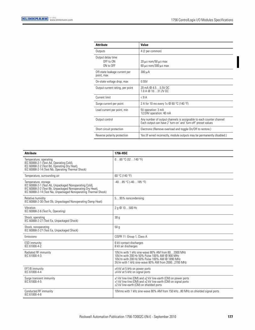
1756 ControlLogix I/O Modules Specificationswww.klinkmann.com6 / 2011
Attribute Value
Outputs 4 (2 per common)
Output delay timeOFF to ONON to OFF
20 μs nom/50 μs max 60 μs nom/300 μs max
Off-state leakage current per point, max
300 μA
On-state voltage drop, max 0.55V
Output current rating, per point 20 mA @ 4.5…5.5V DC1.0 A @ 10…31.2V DC
Current limit < 9 A
Surge current per point 2 A for 10 ms every 1s @ 60 °C (140 °F)
Load current per point, min 5V operation: 3 mA 12/24V operation: 40 mA
Output control Any number of output channels is assignable to each counter channelEach output can have 2 ’turn-on’ and ’turn-off’ preset values
Short circuit protection Electronic (Remove overload and toggle On/Off to restore.)
Reverse polarity protection Yes (If wired incorrectly, module outputs may be permanently disabled.)
Attribute 1756-HSC
Temperature, operatingIEC 60068-2-1 (Test Ad, Operating Cold),IEC 60068-2-2 (Test Bd, Operating Dry Heat),IEC 60068-2-14 (Test Nb, Operating Thermal Shock)
0…60 °C (32…140 °F)
Temperature, surrounding air 60 °C (140 °F)
Temperature, storageIEC 60068-2-1 (Test Ab, Unpackaged Nonoperating Cold),IEC 60068-2-2 (Test Bb, Unpackaged Nonoperating Dry Heat),IEC 60068-2-14 (Test Na, Unpackaged Nonoperating Thermal Shock)
-40…85 °C (-40…185 °F)
Relative humidityIEC 60068-2-30 (Test Db, Unpackaged Nonoperating Damp Heat)
5…95% noncondensing
VibrationIEC 60068-2-6 (Test Fc, Operating)
2 g @ 10…500 Hz
Shock, operatingIEC 60068-2-27 (Test Ea, Unpackaged Shock)
30 g
Shock, nonoperatingIEC 60068-2-27 (Test Ea, Unpackaged Shock)
50 g
Emissions CISPR 11: Group 1, Class A
ESD immunityIEC 61000-4-2
6 kV contact discharges8 kV air discharges
Radiated RF immunityIEC 61000-4-3
10V/m with 1 kHz sine-wave 80% AM from 80... 2000 MHz10V/m with 200 Hz 50% Pulse 100% AM @ 900 MHz10V/m with 200 Hz 50% Pulse 100% AM @ 1890 MHz3V/m with 1 kHz sine-wave 80% AM from 2000...2700 MHz
EFT/B immunityIEC 61000-4-4
±4 kV at 5 kHz on power ports±4 kV at 5 kHz on signal ports
Surge transient immunityIEC 61000-4-5
±1 kV line-line (DM) and ±2 kV line-earth (CM) on power ports±1 kV line-line (DM) and ±2 kV line-earth (CM) on signal ports±2 kV line-earth (CM) on shielded ports
Conducted RF immunityIEC 61000-4-6
10Vrms with 1 kHz sine-wave 80% AM from 150 kHz...80 MHz on shielded signal ports
Rockwell Automation Publication 1756-TD002C-EN-E - September 2010 177
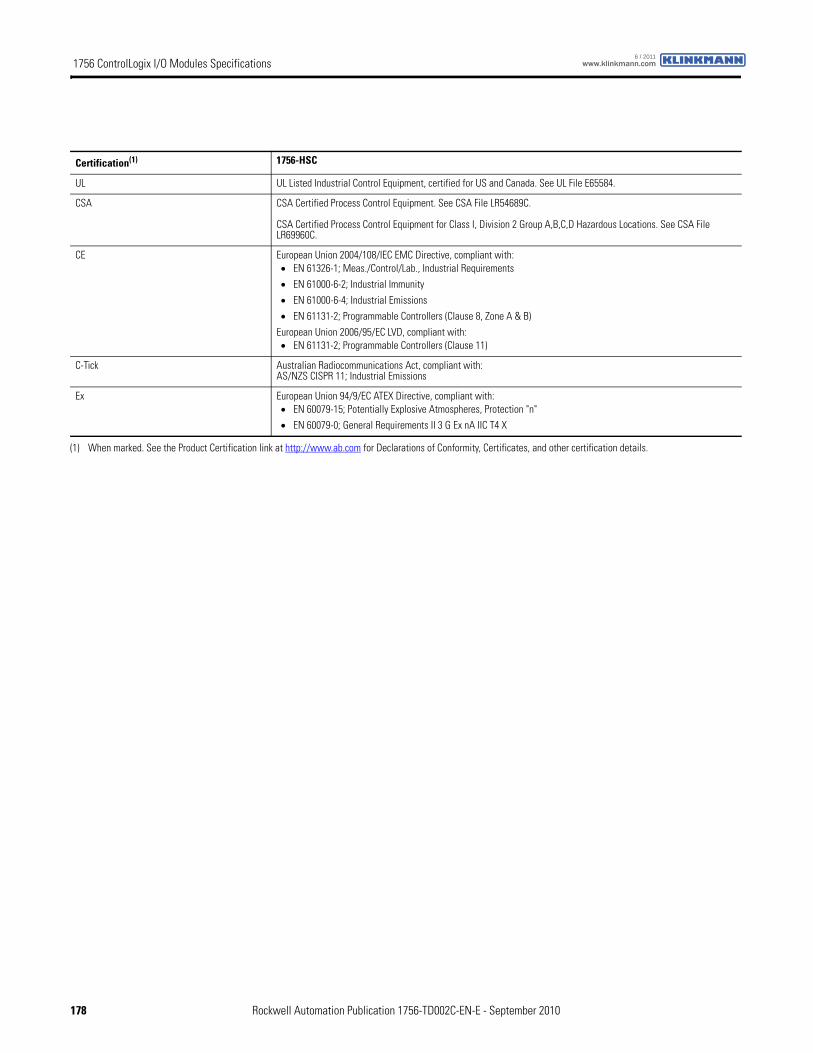
1756 ControlLogix I/O Modules Specifications www.klinkmann.com6 / 2011
Certification(1) 1756-HSC
UL UL Listed Industrial Control Equipment, certified for US and Canada. See UL File E65584.
CSA CSA Certified Process Control Equipment. See CSA File LR54689C.
CSA Certified Process Control Equipment for Class I, Division 2 Group A,B,C,D Hazardous Locations. See CSA File LR69960C.
CE European Union 2004/108/IEC EMC Directive, compliant with:• EN 61326-1; Meas./Control/Lab., Industrial Requirements
• EN 61000-6-2; Industrial Immunity
• EN 61000-6-4; Industrial Emissions
• EN 61131-2; Programmable Controllers (Clause 8, Zone A & B)
European Union 2006/95/EC LVD, compliant with:• EN 61131-2; Programmable Controllers (Clause 11)
C-Tick Australian Radiocommunications Act, compliant with:AS/NZS CISPR 11; Industrial Emissions
Ex European Union 94/9/EC ATEX Directive, compliant with:• EN 60079-15; Potentially Explosive Atmospheres, Protection "n"
• EN 60079-0; General Requirements II 3 G Ex nA IIC T4 X
(1) When marked. See the Product Certification link at http://www.ab.com for Declarations of Conformity, Certificates, and other certification details.
178 Rockwell Automation Publication 1756-TD002C-EN-E - September 2010
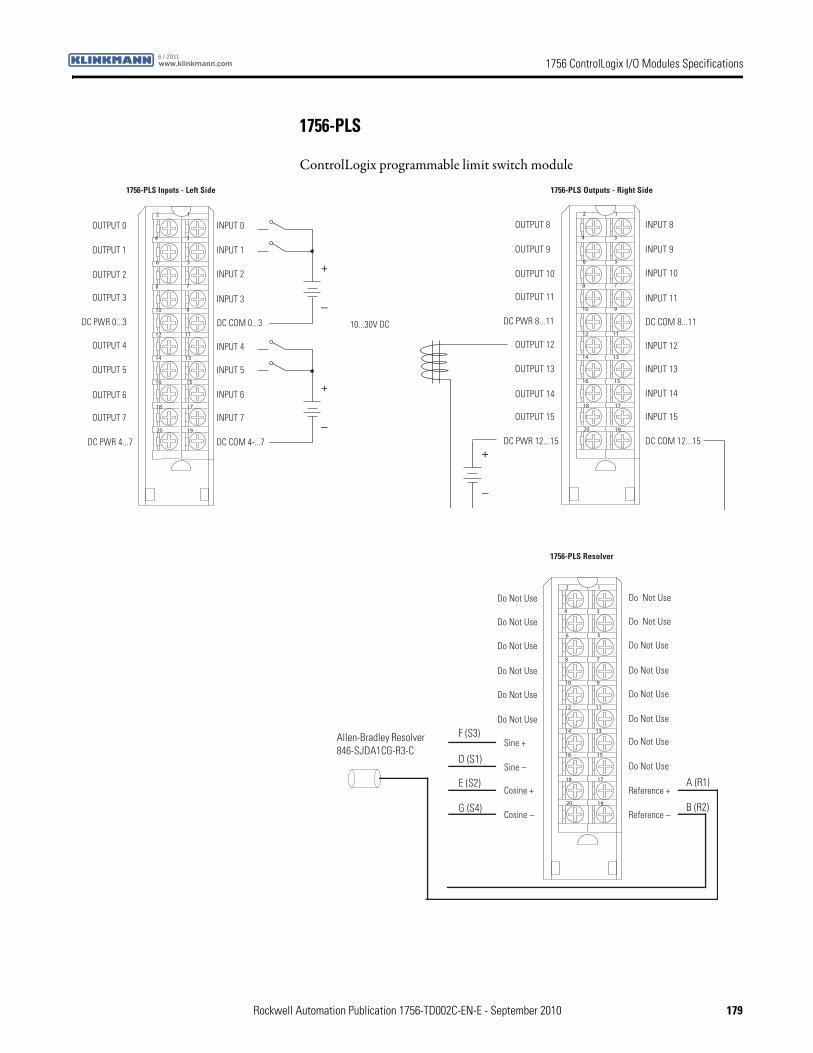
1756 ControlLogix I/O Modules Specificationswww.klinkmann.com6 / 2011
1756-PLS
ControlLogix programmable limit switch module
+
_
+
_
OUTPUT 0
OUTPUT 1
OUTPUT 2
OUTPUT 3
DC PWR 0...3
INPUT 1
INPUT 0
OUTPUT 4
OUTPUT 7
DC PWR 4...7
OUTPUT 5
OUTPUT 6
INPUT 2
INPUT 3
INPUT 4
INPUT 5
INPUT 6
INPUT 7
DC COM 4-...7
12
34
56
78
910
1112
1314
1516
1718
1920
10...30V DC
1756-PLS Inputs - Left Side
DC COM 0...3
+
_
OUTPUT 8
OUTPUT 9
OUTPUT 10
OUTPUT 11
DC PWR 8...11
INPUT 9
INPUT 8
OUTPUT 12
OUTPUT 15
DC PWR 12...15
OUTPUT 13
OUTPUT 14
INPUT 10
INPUT 11
INPUT 12
INPUT 13
INPUT 14
INPUT 15
DC COM 12...15
12
34
56
78
910
1112
1314
1516
1718
1920
1756-PLS Outputs - Right Side
DC COM 8...11
Do Not Use
Sine +
Sine –
Cosine +
Cosine –
12
34
56
78
910
1112
1314
1516
1718
1920
Allen-Bradley Resolver 846-SJDA1CG-R3-C
F (S3)
D (S1)
E (S2)
G (S4)
A (R1)
B (R2)
Reference +
Reference –
Do Not Use
Do Not Use
Do Not Use
Do Not Use
Do Not Use
Do Not Use
Do Not Use
Do Not Use
Do Not Use
Do Not Use
Do Not Use
Do Not Use
Do Not Use
1756-PLS Resolver
Rockwell Automation Publication 1756-TD002C-EN-E - September 2010 179
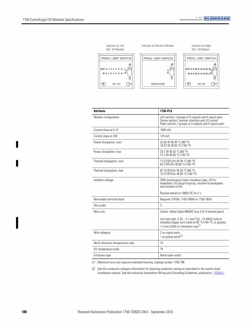
1756 ControlLogix I/O Modules Specifications www.klinkmann.com6 / 2011
Attribute 1756-PLS
Module configuration Left section: 2 groups of 4 outputs and 4 inputs eachCenter section: resolver interface and I/O controlRight section: 2 groups of 4 outputs and 4 inputs each
Current draw at 5.1V 1000 mA
Current draw at 24V 125 mA
Power dissipation, nom 22.62 W @ 30 °C (86 °F)18.22 W @ 60 °C (140 °F)
Power dissipation, max 25.7 W @ 30 °C (86 °F)21.3 W @ 60 °C (140 °F)
Thermal dissipation, nom 77.23 BTU/hr @ 30 °C (86 °F)62.2 BTU/hr @ 60 °C (140 °F)
Thermal dissipation, max 87.74 BTU/hr @ 30 °C (86 °F)72.72 BTU/hr @ 60 °C (140 °F)
Isolation voltage 250V (continuous), basic insulation type, I/O-to-backplane, I/O group-to-group, resolver-to-backplane, and resolver-to-I/O
Routine tested at 1900V DC for 2 s
Removable terminal block Requires 3 RTBs: 1756-TBNH or 1756-TBSH
Slot width 3
Wire size Center: Alpha Cable #6054C (use 3 of 4 twisted pairs)
Left and right: 0.33... 2.1 mm2 (22...14 AWG) solid or stranded copper wire rated at 90 °C (194 °F), or greater, 1.2 mm (3/64 in.) insulation max(1)
(1) Maximum wire size requires extended housing, catalog number 1756-TBE.
Wire category 2 on signal ports1 on power ports(2)
(2) Use this conductor category information for planning conductor routing as described in the system-level installation manual. See the Industrial Automation Wiring and Grounding Guidelines, publication 1770-4.1.
North American temperature code T4
IEC temperature code T4
Enclosure type None (open style)
OK
0 OK
31 42 5 6 7
0 31 42 5 6 7
OUT
IN
PROG. LIMIT SWITCHPROG. LIMIT SWITCH
REVLOSERO/I CD
8 OK
119 1210 13 14 15OUT
IN
PROG. LIMIT SWITCH
DC I/O
8 119 1210 13 14 15
Indicator for Left Slot I/O Module
Indicator for Resolver Module Indicator for Right Slot I/O Module
180 Rockwell Automation Publication 1756-TD002C-EN-E - September 2010
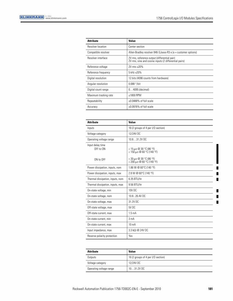
1756 ControlLogix I/O Modules Specificationswww.klinkmann.com6 / 2011
Attribute Value
Resolver location Center section
Compatible resolver Allen-Bradley resolver 846-SJxxxx-R3-x (x = customer options)
Resolver interface 2V rms, reference output (differential pair)2V rms, sine and cosine inputs (2 differential pairs)
Reference voltage 2V rms ±20%
Reference frequency 5 kHz ±20%
Digital resolution 12 bits (4096 counts from hardware)
Angular resolution 0.088 °/bit
Digital count range 0…4095 (decimal)
Maximum tracking rate ±1800 RPM
Repeatability ±0.0488% of full scale
Accuracy ±0.0976% of full scale
Attribute Value
Inputs 16 (2 groups of 4 per I/O section)
Voltage category 12/24V DC
Operating voltage range 10.8…31.2V DC
Input delay timeOFF to ON
ON to OFF
< 15 μs @ 30 °C (86 °F)< 150 μs @ 60 °C (140 °F)
< 30 μs @ 30 °C (86 °F)< 200 μs @ 60 °C (140 °F)
Power dissipation, inputs, nom 1.86 W @ 60°C (140 °F)
Power dissipation, inputs, max 2.8 W @ 60°C (140 °F)
Thermal dissipation, inputs, nom 6.35 BTU/hr
Thermal dissipation, inputs, max 9.56 BTU/hr
On-state voltage, min 10V DC
On-state voltage, nom 10.8...26.4V DC
On-state voltage, max 31.2V DC
Off-state voltage, max 5V DC
Off-state current, max 1.5 mA
On-state current, min 3 mA
On-state current, max 10 mA
Input impedance, max 3.3 kΩ @ 24V DC
Reverse polarity protection Yes
Attribute Value
Outputs 16 (2 groups of 4 per I/O section)
Voltage category 12/24V DC
Operating voltage range 10…31.2V DC
Rockwell Automation Publication 1756-TD002C-EN-E - September 2010 181
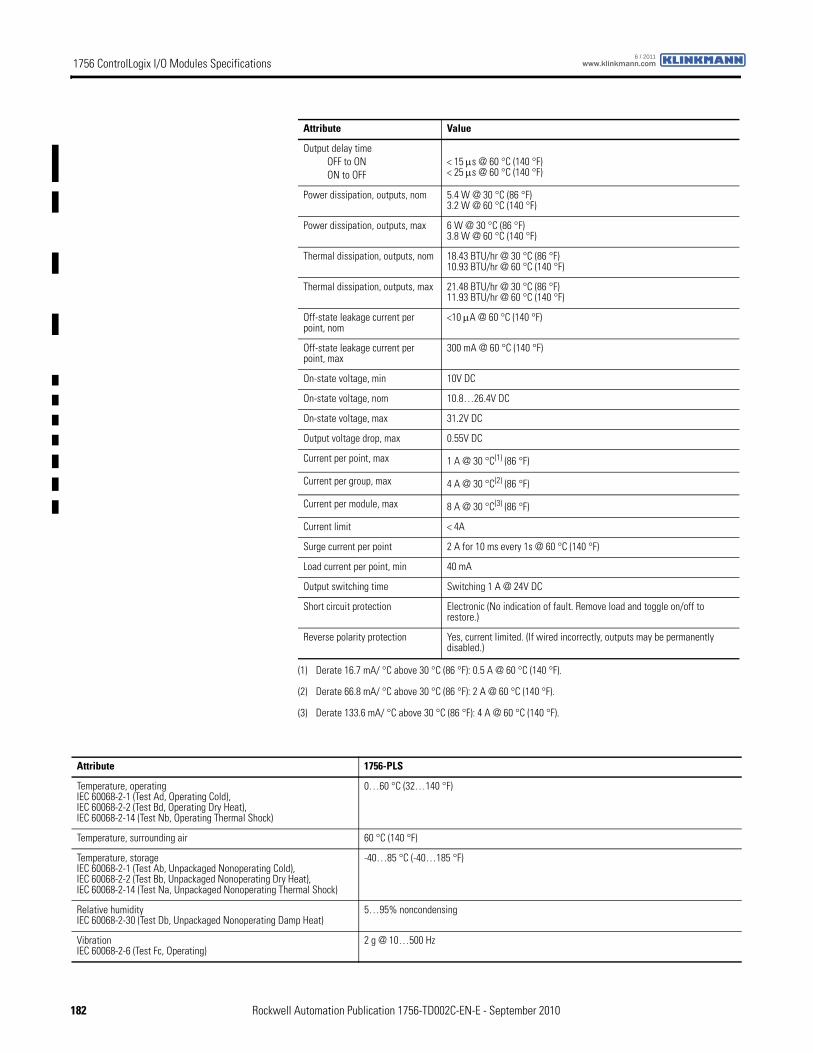
1756 ControlLogix I/O Modules Specifications www.klinkmann.com6 / 2011
Output delay timeOFF to ONON to OFF
< 15 μs @ 60 °C (140 °F) < 25 μs @ 60 °C (140 °F)
Power dissipation, outputs, nom 5.4 W @ 30 °C (86 °F)3.2 W @ 60 °C (140 °F)
Power dissipation, outputs, max 6 W @ 30 °C (86 °F)3.8 W @ 60 °C (140 °F)
Thermal dissipation, outputs, nom 18.43 BTU/hr @ 30 °C (86 °F)10.93 BTU/hr @ 60 °C (140 °F)
Thermal dissipation, outputs, max 21.48 BTU/hr @ 30 °C (86 °F)11.93 BTU/hr @ 60 °C (140 °F)
Off-state leakage current per point, nom
<10 μA @ 60 °C (140 °F)
Off-state leakage current per point, max
300 mA @ 60 °C (140 °F)
On-state voltage, min 10V DC
On-state voltage, nom 10.8…26.4V DC
On-state voltage, max 31.2V DC
Output voltage drop, max 0.55V DC
Current per point, max 1 A @ 30 °C(1) (86 °F)
Current per group, max 4 A @ 30 °C(2) (86 °F)
Current per module, max 8 A @ 30 °C(3) (86 °F)
Current limit < 4A
Surge current per point 2 A for 10 ms every 1s @ 60 °C (140 °F)
Load current per point, min 40 mA
Output switching time Switching 1 A @ 24V DC
Short circuit protection Electronic (No indication of fault. Remove load and toggle on/off to restore.)
Reverse polarity protection Yes, current limited. (If wired incorrectly, outputs may be permanently disabled.)
(1) Derate 16.7 mA/ °C above 30 °C (86 °F): 0.5 A @ 60 °C (140 °F).
(2) Derate 66.8 mA/ °C above 30 °C (86 °F): 2 A @ 60 °C (140 °F).
(3) Derate 133.6 mA/ °C above 30 °C (86 °F): 4 A @ 60 °C (140 °F).
Attribute Value
Attribute 1756-PLS
Temperature, operatingIEC 60068-2-1 (Test Ad, Operating Cold),IEC 60068-2-2 (Test Bd, Operating Dry Heat),IEC 60068-2-14 (Test Nb, Operating Thermal Shock)
0…60 °C (32…140 °F)
Temperature, surrounding air 60 °C (140 °F)
Temperature, storageIEC 60068-2-1 (Test Ab, Unpackaged Nonoperating Cold),IEC 60068-2-2 (Test Bb, Unpackaged Nonoperating Dry Heat),IEC 60068-2-14 (Test Na, Unpackaged Nonoperating Thermal Shock)
-40…85 °C (-40…185 °F)
Relative humidityIEC 60068-2-30 (Test Db, Unpackaged Nonoperating Damp Heat)
5…95% noncondensing
VibrationIEC 60068-2-6 (Test Fc, Operating)
2 g @ 10…500 Hz
182 Rockwell Automation Publication 1756-TD002C-EN-E - September 2010

1756 ControlLogix I/O Modules Specificationswww.klinkmann.com6 / 2011
Shock, operatingIEC 60068-2-27 (Test Ea, Unpackaged Shock)
30 g
Shock, nonoperatingIEC 60068-2-27 (Test Ea, Unpackaged Shock)
50 g
Emissions CISPR 11: Group 1, Class A
ESD immunityIEC 61000-4-2
6 kV contact discharges8 kV air discharges
Radiated RF immunityIEC 61000-4-3
10V/m with 1 kHz sine-wave 80% AM from 80... 2000 MHz10V/m with 200 Hz 50% Pulse 100% AM @ 900 MHz10V/m with 200Hz 50% Pulse 100% AM @ 1890 MHz3V/m with 1 kHz sine-wave 80% AM from 2000...2700 MHz
EFT/B immunityIEC 61000-4-4
±4 kV at 5 kHz on unshielded I/O and power ports±2 kV at 5 kHz on shielded resolver ports
Surge transient immunityIEC 61000-4-5
±1 kV line-line (DM) and ±2 kV line-earth (CM) on unshielded I/O and power ports±2 kV line-earth (CM) on shielded resolver ports
Conducted RF immunityIEC 61000-4-6
10Vrms with 1 kHz sine-wave 80% AM from 150 kHz...80 MHz on shielded signal ports
Attribute 1756-PLS
Certification(1) 1756-PLS
UL UL Listed Industrial Control Equipment, certified for US and Canada. See UL File E65584.
CSA CSA Certified Process Control Equipment. See CSA File LR54689C.
CSA Certified Process Control Equipment for Class I, Division 2 Group A,B,C,D Hazardous Locations. See CSA File LR69960C.
CE European Union 2004/108/IEC EMC Directive, compliant with:• EN 61326-1; Meas./Control/Lab., Industrial Requirements
• EN 61000-6-2; Industrial Immunity
• EN 61000-6-4; Industrial Emissions
• EN 61131-2; Programmable Controllers (Clause 8, Zone A & B)
European Union 2006/95/EC LVD, compliant with:• EN 61131-2; Programmable Controllers (Clause 11)
C-Tick Australian Radiocommunications Act, compliant with:AS/NZS CISPR 11; Industrial Emissions
Ex European Union 94/9/EC ATEX Directive, compliant with:• EN 60079-15; Potentially Explosive Atmospheres, Protection "n"
• EN 60079-0; General Requirements II 3 G Ex nA IIC T4 X
(1) When marked. See the Product Certification link at http://www.ab.com for Declarations of Conformity, Certificates, and other certification details.
Rockwell Automation Publication 1756-TD002C-EN-E - September 2010 183
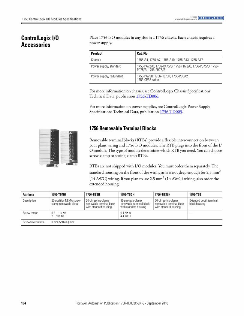
1756 ControlLogix I/O Modules Specifications www.klinkmann.com6 / 2011
ControlLogix I/O Accessories
Place 1756 I/O modules in any slot in a 1756 chassis. Each chassis requires a power supply.
For more information on chassis, see ControlLogix Chassis Specifications Technical Data, publication 1756-TD006.
For more information on power supplies, see ControlLogix Power Supply Specifications Technical Data, publication 1756-TD005.
1756 Removable Terminal Blocks
Removable terminal blocks (RTBs) provide a flexible interconnection between your plant wiring and 1756 I/O modules. The RTB plugs into the front of the I/O module. The type of module determines which RTB you need. You can choose screw-clamp or spring-clamp RTBs.
RTBs are not shipped with I/O modules. You must order them separately. The standard housing on the front of the wiring arm is not deep enough for 2.5 mm2 (14 AWG) wiring. If you plan to use 2.5 mm2 (14 AWG) wiring, also order the extended housing.
Product Cat. No.
Chassis 1756-A4, 1756-A7, 1756-A10, 1756-A13, 1756-A17
Power supply, standard 1756-PA72/C, 1756-PA75/B, 1756-PB72/C, 1756-PB75/B, 1756-PC75/B, 1756-PH75/B
Power supply, redundant 1756-PA75R, 1756-PB75R, 1756-PSCA21756-CPR2 cable
Attribute 1756-TBNH 1756-TBSH 1756-TBCH 1756-TBS6H 1756-TBE
Description 20-position NEMA screw-clamp removable block
20-pin spring-clamp removable terminal block with standard housing
36-pin cage-clamp removable terminal block with standard housing
36-pin spring-clamp removable terminal block with standard housing
Extended depth terminal block housing
Screw torque 0.8…1 N•m7…9 lb•in
0.4 N•m4.4 lb•in
—
Screwdriver width 8 mm (5/16 in.) max
184 Rockwell Automation Publication 1756-TD002C-EN-E - September 2010
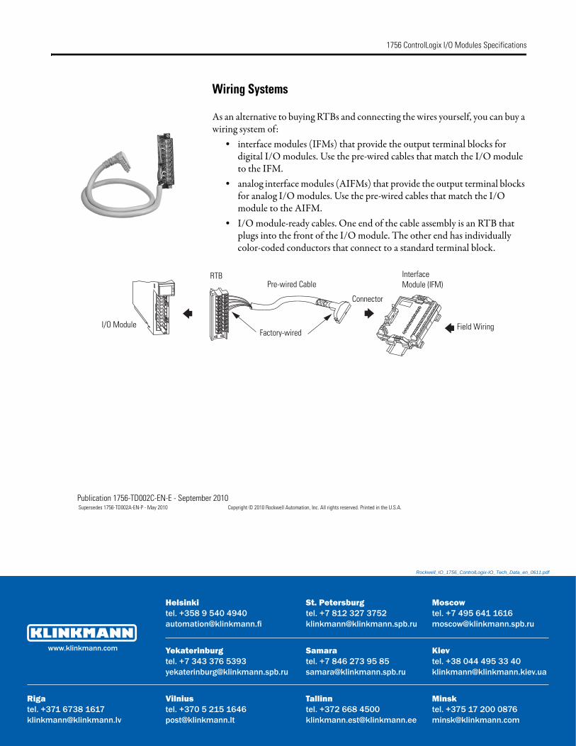
1756 ControlLogix I/O Modules Specifications
11.pdf
Rigatel. +klink
ua
Wiring Systems
As an alternative to buying RTBs and connecting the wires yourself, you can buy a wiring system of:• interface modules (IFMs) that provide the output terminal blocks for
digital I/O modules. Use the pre-wired cables that match the I/O module to the IFM.
• analog interface modules (AIFMs) that provide the output terminal blocks for analog I/O modules. Use the pre-wired cables that match the I/O module to the AIFM.
• I/O module-ready cables. One end of the cable assembly is an RTB that plugs into the front of the I/O module. The other end has individually color-coded conductors that connect to a standard terminal block.
RTB
I/O ModuleFactory-wired
Pre-wired Cable
Connector
Interface Module (IFM)
Field Wiring
Publication 1756-TD002C-EN-E - September 2010 Supersedes 1756-TD002A-EN-P - May 2010 Copyright © 2010 Rockwell Automation, Inc. All rights reserved. Printed in the U.S.A.
Rockwell_IO_1756_ControlLogix-IO_Tech_Data_en_06
Samaratel. +7 846 273 95 [email protected]
Yekaterinburgtel. +7 343 376 [email protected]
St. Petersburgtel. +7 812 327 [email protected]
Moscowtel. +7 495 641 [email protected]
Helsinkitel. +358 9 540 [email protected]
Vilnius МinskTallinn
Кievtel. +38 044 495 33 [email protected].
www.klinkmann.com
tel. +370 5 215 [email protected]
371 6738 [email protected]
tel. +375 17 200 [email protected]
tel. +372 668 [email protected]