roadway intersection lighting - … iii 2015 presentations...roadway & intersection lighting ......
TRANSCRIPT
Roadway & Intersection LightingJuly 15, 2015
1
Rochelle Garrett, PEWilliam Parman

Brief History of Lighting
2
First use of street lighting is believed to be in Ancient Greece around the 4th Century in the City of Antioch.
Next significant use was in Cordova in the Arab Empire around 9thand 10th Century, then London in about 1417.
It was introduced in the US by Benjamin Franklin in Philadelphia, using candles in lanterns which he fashioned to have 4 separate glass sides.
William Murdoch introduced gas lighting to London in 1792 and the US followed soon with gas lighting in Newport RI around 1803.

3
Electric Light bulbs for street lamps were developed soon after Edison’s invention of the incandescent bulb
The first City to use electric lights was Wabash Indiana in 1880.
Introduced in 1948 mercury vapor was the first major improvement to the incandescent street light.
In 1957 Westinghouse introduced the cobrahead, GE its followed later with its own version.
High Pressure Sodium (HPS) was invented in 1970 and in wide use since the 80’s.
Light Emitting Diode (LED) Roadway Luminaire not introduced until more recently, mid 2000’s, is FDOT preferred lighting on new systems.
Brief History of Lighting
Wikipedia

4
Purpose
• Reduce nighttime vehicle crashes , injuries and fatalities
• Reduce nighttime pedestrian and bicycle crashes, injuries and fatalities

Safety
5
Numerous studies have shown nighttime fatal crashes have been reduced up to 60% with installation of roadway lighting.*
Elvik and Vaa (2004) 64% reduction of fatal crashes, 28% reduction and 17% reduction in property damage only crashes after lighting installed.
Per Ole Wanvik (2009) 28% reduction in injury crashes, 60% reduction in fatal crashes, a 45% reduction in injury crashes involving pedestrians
Minnesota Local Road Research Board (2006) before and after study found that 44% of the intersections showed reduction in number of nighttime crashes.
*FHWA Lighting Handbook Aug 2012

Highway Safety Improvements with the Highest Benefit‐Cost Ratios (1974‐1995)*
1. Illumination 26.8
2. Upgrade Median Barrier 22.6
3. Traffic Signs 22.4
4. Relocate/Breakaway Util. Poles 17.7
5. Remove Obstacles 10.7
6. New Traffic Signals 8.5
7. Impact Attenuators 8.0
8. New Median Barrier 7.6
9. Upgrade Guardrail 7.5
10. Upgrade Traffic Signals 7.4
6*Review of the Safety Benefits and Other Effects of Roadway Lighting for NCHRP/TRB June 2009

Positive Impacts
Improve view of roadway geometry and adjacent environment.
Increase sight distance to improve response to hazards and decision points.
Eliminate dark spots and improve the mutual view of motorists and pedestrians.
Provide clearer view during police, emergency, construction and maintenance activities or events.
7

Positive Impacts
8
Well designed lighting helps with adjustment to avoid affects of glare
Roadway lighting helps the eye adapt to increased levels of luminance
Older drivers and pedestrians benefit from increased lighting levels

Negative Impacts
Glare‐ often referred to as Veiling Luminance
Spill light – light that falls outside the area intended to be lit
Sky Glow – Light that is reflected up into the atmosphere from source, road or other surfaces
9
•Light Trespass

10
•Light Trespass
FHWA Lighting Handbook Aug 2012
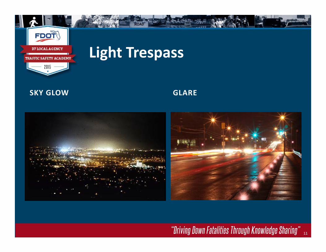
Light Trespass
SKY GLOW GLARE
11

Lighting Justification
Follow the guidance outlined in the Manual on Uniform Traffic Studies, chapter 15
Requires a Letter of Acceptance or Memo of Understanding (MOU)
Safety analysis or study showing that lighting would be a cost –effective alternative or countermeasure using the AASHTO or (HSM)predictive or other methodology
Meeting the warrants does not guarantee that lighting must beinstalled
12
Warrant analysis is required for FDOT Projects

Lighting Justification
Step 1
AASHTO Warrants
Traffic Volumes (ADT)
Ratio of Night to Day Crashes (2.0 or greater)
Local Government Participation in Cost‐ local government agreements
25 % (or greater) Nighttime crashes
13MUTS Chapter15
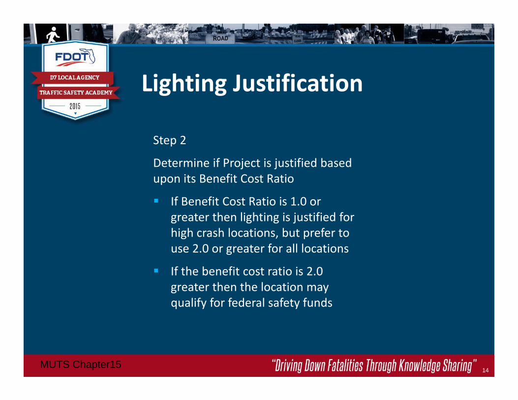
Lighting Justification
Step 2
Determine if Project is justified based upon its Benefit Cost Ratio
If Benefit Cost Ratio is 1.0 or greater then lighting is justified for high crash locations, but prefer to use 2.0 or greater for all locations
If the benefit cost ratio is 2.0 greater then the location may qualify for federal safety funds
14MUTS Chapter15

Lighting Justification
15
Map showing corridors with 25% or greater nighttime crashes
Available through District 7 Traffic Operations Safety Office
http://d7sharepoint.dot.state.fl.us/Operations/trafficSafety/Miscellaneous/Maps/Forms/AllItems.aspx
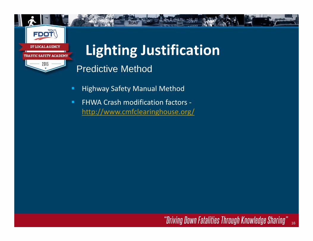
Highway Safety Manual Method
FHWA Crash modification factors ‐http://www.cmfclearinghouse.org/
16
Lighting JustificationPredictive Method

FDOT policy to light all interchanges
Lighting in adjacent areas
Presence of crosswalks or medians
Constructability, feasibility
Engineering Judgement
17
Lighting JustificationOther Important factors:

Lighting Analysis
Software packages
1. AGI 32
2. Visual
3. Cala‐holophane
4. Alladin‐GE
18

Lighting Analysis Report
Project overview or description (location)
Purpose‐ specify lighting criteria, document methodology for selection
Procedure‐ project designed to FDOT standards and PPM
Analysis‐ software tool used Alternatives‐ (parameters) describe luminaires (LED for new system), wattage, mounting
height, cost comparisons, pole spacing
Design‐ criteria , photo metric analysis and lighting calculations
Recommendations
Lighting and Voltage Drop Calculations (Appendices)
19

LIGHTING ANALYSIS
20

Selection Factors
Meets or exceeds , standards and specifications
Photometric performance
Durability, Aesthetics
Availability
Maintenance requirements
Costs‐initial and operation
21

Florida Department of Transportation (FDOT)FDOT Design StandardsPlans Preparation Manual (PPM)
Federal Highway Administration (FHWA) American Association State Highway Transportation Officials
(AASHTO) Illuminating Engineering Society of North America (IESNA) Local Agencies and Power Companies
22
Design Standards

Design Standards
FDOT lighting standards can be found in the Design Standard Indexes 17500 to 17515
23FDOT Design Standard Index 17515

24
Staggered Median
Design Standards

25
One Side Opposite
Design Standards

26
Design Standards

Design Standards
FDOT lighting clear zone requirements for Conventional Lighting
• Urban curb and gutter < 45 – minimum 4’ from face of curb
• All other roadways ‐ 20’ from travel lane or clear zone if less than 20’
• Breakaway supports unless median barrier mounted or shielded
27PPM vol. 1 Chapter 2 Table 2.11.2

The Department uses the illuminance technique for all lighting design.
Illuminance – It is a measure of how much light illuminates a surface.
Foot‐candle – The illuminance cast on a surface by a one‐candela source one foot away.
28
Design Standards
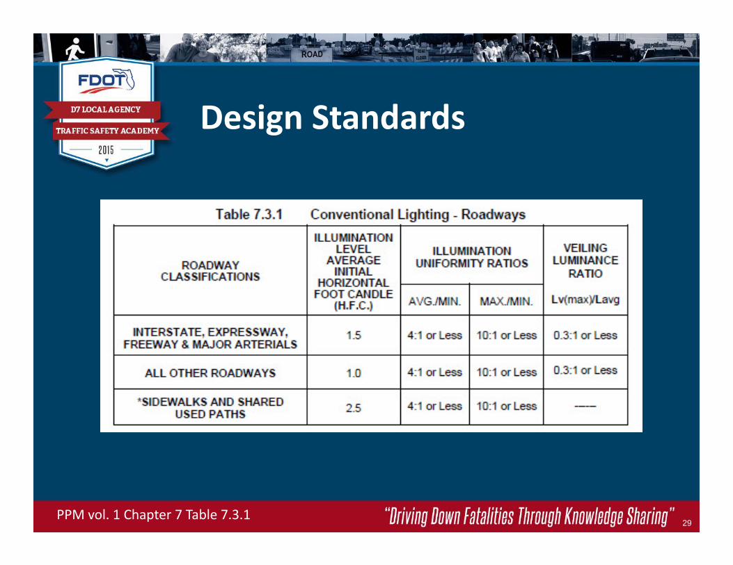
Design Standards
29PPM vol. 1 Chapter 7 Table 7.3.1

Design Standards
Example of poor uniformity ratios
30

Proposed Design Standards
Where are we going?
Proposed changes to Chapter 7 include:
1. Methodology
Analysis Zones
Use Polygon Method for all Photometric Calculations
Lighting Criteria
2. Intersection Criteria
31

Proposed Design Standards
Urban and Rural FDOT Facilities Divided Roadway Segments Undivided Roadway Segments Signalized Intersection Segments

Proposed Design Standards
Photometric Calculations – Polygon Method
Roadway Segments15 Feet Longitudinally5 Feet Transversely
Signalized Intersection Segments5 Feet Longitudinally5 Feet Transversely
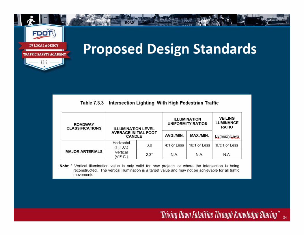
34
Proposed Design Standards

Proposed Design Standards
Vertical Illuminance is the primary design value to be used to measure pedestrian visibility.

Proposed Design Standards
The vertical illuminance calculation method to be used at intersections will be the variable light meter aimed toward the driver’s location.
The driver’s location from the approach to the crosswalk is established based on the stopping sight distance for the posted approach speed.

Proposed Design Standards
The vertical illuminance method will be calculated for three movements at the intersection.
1. Near Side Crosswalk Approach2. Right Turn Movement3. Left Turn Movement

Proposed Design StandardsNear Side Approach

Proposed Design StandardsRight Turn Movement

Proposed Design StandardsLeft Turn Movement

Lighting Challenges
Intersection Luminaire Photometrics
High Overall Lighting Levels
Transition Lighting Requirements

42
Turtle Nesting http://ca.dep.state.fl.us/mapdirect
Nocturnal Animals
Development
Pedestrian activity level (conflicts)
Lighting Challenges

Roadside safety considerations
Available power
Presence of overhead and underground utilities
Proximity to Railroads and Airports
Maintenance agreements
Existing lighting
43
Lighting Challenges

Lighting Challenges
44
Transmission Lines
Other Utilities
Neutral LineOSHA Min.Clearance
Voltage (kV)
X (Min. ClearanceDist. in ft.)
Up to 50 10
>50 - 200 15
>200 - 350 20
>350 - 500 25
>500 - 750 35
>750 -1000
45
>1000 As per utility owner /reg. prof. engineer
X’

LOCATION MATTERS
Stay out of the bottom of the
ditch
45
Lighting Challenges
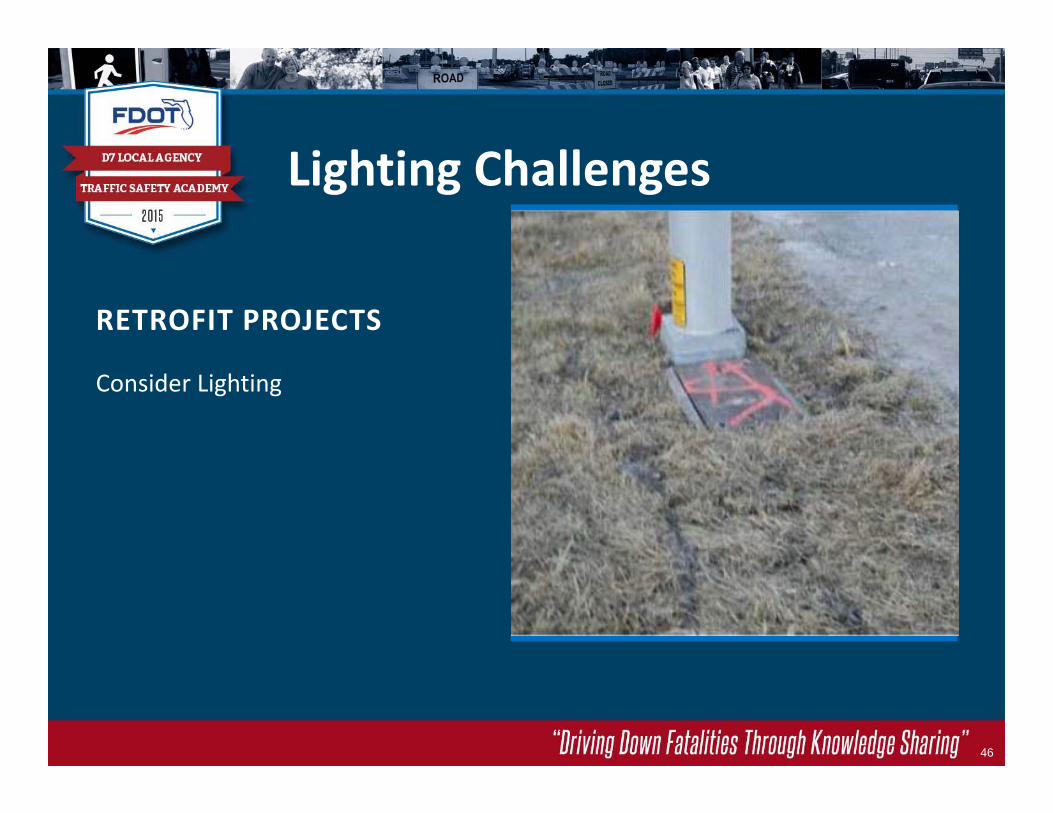
RETROFIT PROJECTS
Consider Lighting
46
Lighting Challenges

RETROFIT PROJECTS
Consider Lighting
47
Lighting Challenges
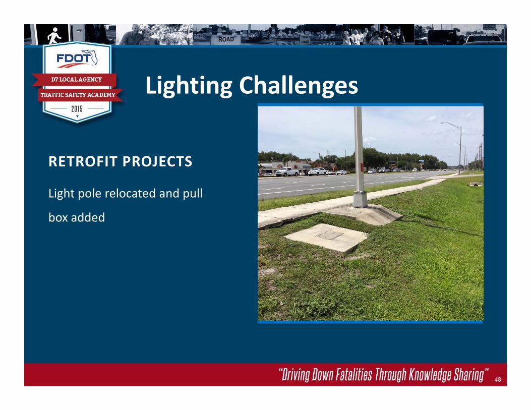
RETROFIT PROJECTS
Light pole relocated and pull
box added
48
Lighting Challenges

RETROFIT PROJECTS
Adjust pole location, path
location, ditch location or all of
the above
49
Lighting Challenges

HIGH MAST LIGHTING
Consider the needs of adjacent
properties and add shades if
needed
50
Lighting Challenges

INTERSECTION LIGHTING
Power Company lighting on
utility pole
51
Lighting Challenges
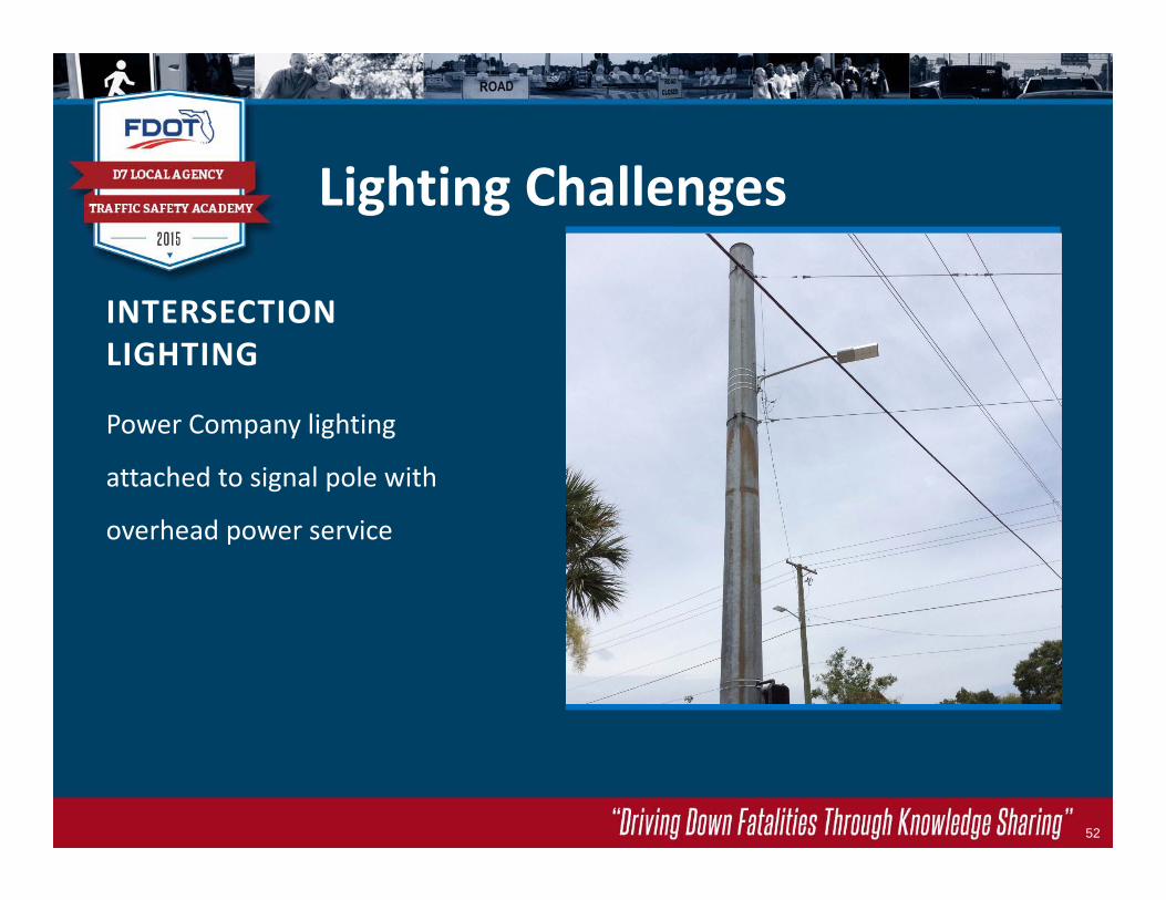
INTERSECTION LIGHTING
Power Company lighting
attached to signal pole with
overhead power service
52
Lighting Challenges

INTERSECTION LIGHTING
LED Lighting installed to
improve pedestrian visibility
53
Lighting Challenges

INTERSECTION LIGHTING
Power Company lighting on
stand‐alone pole
54
Lighting Challenges

DAY NIGHT
55
Lighting Challenges

INTERSECTION LIGHTING
Stand‐alone DOT pole
56
Lighting Challenges

INTERSECTION LIGHTING
DOT luminaire attached to a
signal pole
57
Lighting Challenges

EXAMPLE OFLUMINAIRE ATTACHMENTAdd note
requiring a
Shop drawing
submittal
58
Lighting Challenges

INTERSECTION LIGHTING
Powered through the traffic signal source
59
Lighting Challenges

INTERSECTION LIGHTING
County owned stand‐alone light poles
60
Lighting Challenges

NIGHT TIME DAYLIGHT
61
Lighting Challenges

INTERSECTION LIGHTING
62
Lighting Challenges
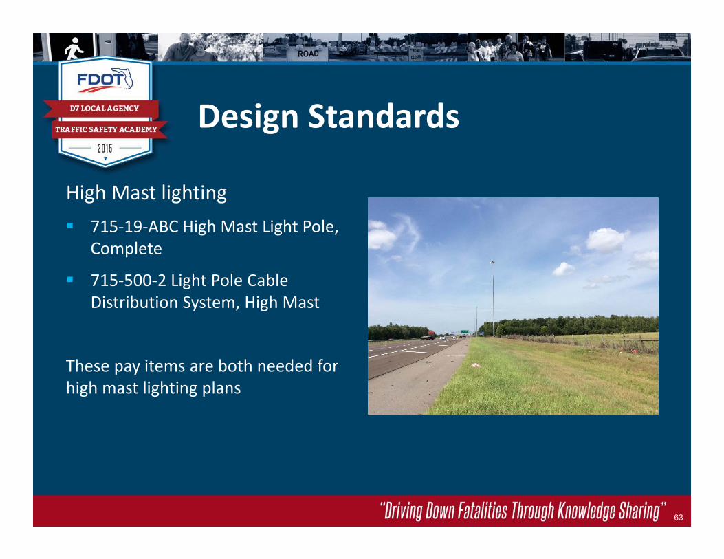
Design Standards
High Mast lighting 715‐19‐ABC High Mast Light Pole,
Complete
715‐500‐2 Light Pole Cable Distribution System, High Mast
These pay items are both needed for high mast lighting plans
63
Sources, Resources and Credits
FHWA‐ Lighting Handbook 2012
FDOT‐ PPM, MUTS, Design Standards, “Greenbook”‐ Ch. 6
ASSHTO‐ Roadway Lighting Design Guide
IESNA (IES)‐ Illuminating Engineering Society of North America
IMSA‐ International Municipal Signal Association
ANSI‐ American National Standards Institute
Chester Henson, State Traffic Standards Engineer
Review of the Safety Benefits and Other Effects of Roadway Lighting for NCHRP –TRB, Final Report‐ Rensselaer Poly Inst. And Penn. State U.
History‐Wikipedia
64

Questions?
65