rl circuit - department of...
TRANSCRIPT
RL Circuit
Equipment: Capstone with 850 interface, 2 voltage sensors, RLC circuit board, 2 male to malebanana leads approximately 80 cm in length
1 Introduction
The three basic linear circuit elements are the resistor, the capacitor, and the inductor. This lab isconcerned with the characteristics of inductors and circuits consisting of a resistor and an inductorin series (RL circuits). The primary focus will be on the response of an RL circuit to a step voltageand a voltage square wave.
2 Theory
2.1 Inductors
An inductor is a 2-terminal circuit element that stores energy in its magnetic field. Inductors areusually constructed by winding a coil with wire. Initially, as the current increases in the coil, amagnetic field begins building across the coil. When the current stops flowing, the inductor willoppose the current change (Lenz’s law) and try to keep the flow of current. This will be doneproducing a current in the opposite direction by the magnetic field it had stored. To increase themagnetic field inductors that are used for low frequencies often have the inside of the coil filledwith a magnetic material. (At high frequencies such coils can be too loosy.) Inductors are the leastperfect of the basic circuit elements due to the resistance of the wire they are made from. Oftenthis resistance is not negligible, which will become apparent when the voltages and currents in anactual circuit are measured.
If a current I is flowing through an inductor, the voltage VL across the inductor is proportionalto the time rate of change of I, or dI
dt . We may write
VL = LdI
dt, (1)
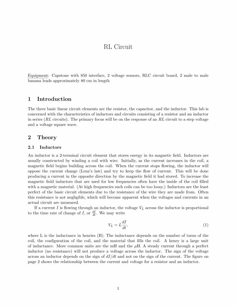
where L is the inductance in henries (H). The inductance depends on the number of turns of thecoil, the configuration of the coil, and the material that fills the coil. A henry is a large unitof inductance. More common units are the mH and the µH. A steady current through a perfectinductor (no resistance) will not produce a voltage across the inductor. The sign of the voltageacross an inductor depends on the sign of dI/dt and not on the sign of the current. The figure onpage 2 shows the relationship between the current and voltage for a resistor and an inductor.
1
General Physics II Lab: RL Circuit
Relationship between current and voltage in a resistor and inductor
The arrow indicates the positive direction of the current through the two devices (resistor andinductor). That is, if the current is in the direction of the arrow, then I > 0. [Note that justbecause the arrows point down doesn’t mean that the current is flowing in the downward direction.The current can also flow in the upwards direction, but in that case I < 0.]
As mentioned above, the coil of wire making up an inductor has some resistance RL. Thisresistance acts like a resistor RL that is in series with an ideal inductor. (An ideal inductor is onewith no resistance.) In this situation, the voltage across the inductor is
VL = LdI
dt+RL I. (2)
3 RL Circuits
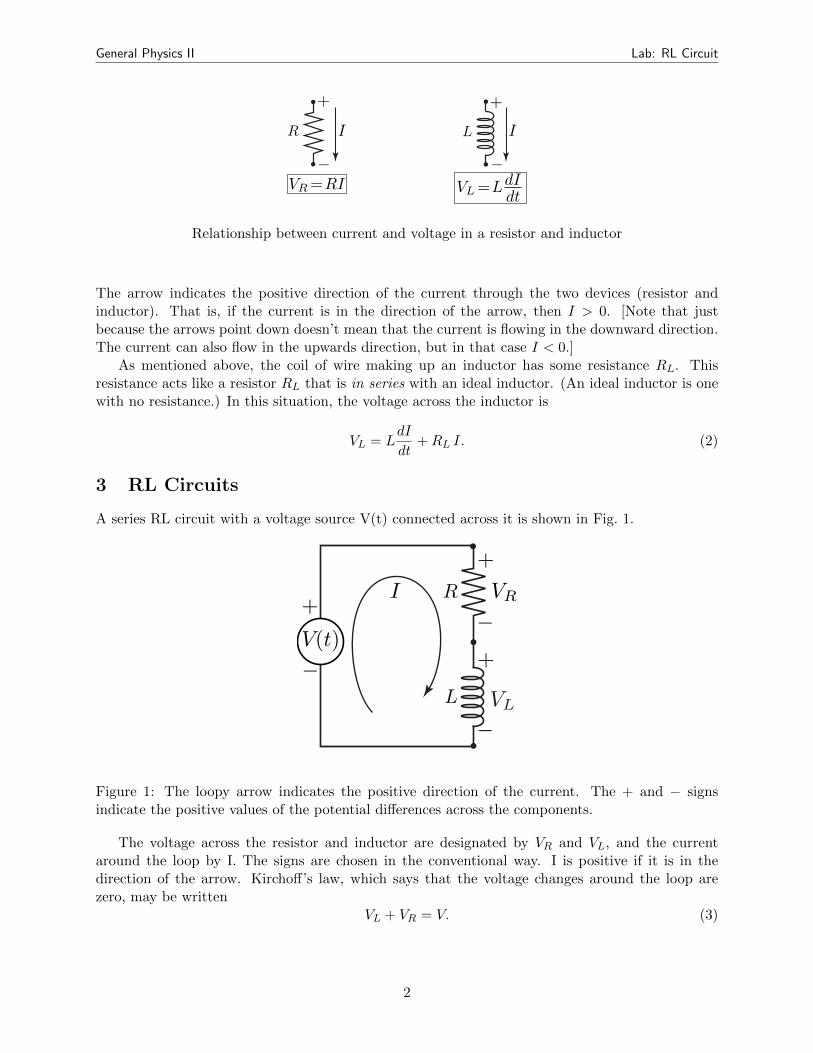
A series RL circuit with a voltage source V(t) connected across it is shown in Fig. 1.
Figure 1: The loopy arrow indicates the positive direction of the current. The + and − signsindicate the positive values of the potential differences across the components.
The voltage across the resistor and inductor are designated by VR and VL, and the currentaround the loop by I. The signs are chosen in the conventional way. I is positive if it is in thedirection of the arrow. Kirchoff’s law, which says that the voltage changes around the loop arezero, may be written
VL + VR = V. (3)
2
General Physics II Lab: RL Circuit
VR Voltage VR across the resistor
0
V0
time
VL Voltage VL across the inductor
0
0
V0
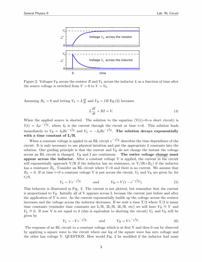
Figure 2: Voltages VR across the resistor R and VL across the inductor L as a function of time afterthe source voltage is switched from V = 0 to V = V0.
Assuming RL = 0 and letting VL = LdIdt and VR = IR Eq.(3) becomes
LdI
dt+RI = V. (4)
When the applied source is shorted. The solution to the equation (V(t)=0=a short circuit) is
I(t) = I0e− t
L/R , where I0 is the current through the circuit at time t=0. This solution leads
immediately to VR = I0Re− t
L/R and VL = −I0Re−t
L/R . The solution decays exponentiallywith a time constant of L/R.
When a constant voltage is appled to an RL circuit e− t
L/R describes the time dependence of thecircuit. It is only necessary to use physical intuition and put the appropriate 2 constants into thesolution. One guiding principle is that the current and VR do not change the instant the voltageacross an RL circuit is changed. VR and I are continuous. The entire voltage change mustappear across the inductor. After a constant voltage V is applied, the current in the circuitwill exponentially approach V/R if the inductor has no resistance, or V/(R+RL) if the inductorhas a resistance RL. Consider an RL circuit where V=0 and there is no current. We assume thatRL = 0. If at time t=0 a constant voltage V is put across the circuit, VL and VR are given by, fort≥0,
VL = V e− t
L/R and VR = V (1 − e− t
L/R ). (5)
This behavior is illustrated in Fig. 2. The current is not plotted, but remember that the currentis proportional to VR. Initially all of V appears across L because the current just before and afterthe application of V is zero. As the current exponentially builds up the voltage across the resistorincreases and the voltage across the inductor decreases. If we wait a time T/2 where T/2 is manytime constants (reminder time constants are L/R, 2L/R, 3L/R, etc) we will have VR ∼= V andVL ∼= 0. If now V is set equal to 0 (this is equivalent to shorting the circuit) VL and VR will begiven by
VL = −V e−t
L/R and VR = V e− t
L/R . (6)
The response of an RL circuit to a constant voltage which is at first V and then 0 can be observedby applying a square wave to the circuit where one leg of the square wave has zero voltage andthe other has voltage V. QUESTION. How would Fig. 2 be modified if the inductor had some
3
General Physics II Lab: RL Circuit
resistance? QUESTION. If T L/R, what is the response of an RL circuit to a symmetric squarewave that oscillates between +V and -V (assume RL = 0)?
If a high frequency square wave, such that T L/R, is applied to an RL circuit, the changesin current and VR are minimal. There is not enough time for the current through the inductor tochange much before the voltage is reversed. If the square wave is not symmetric with respect toground the average VR will be the average voltage of the square wave, assuming RL = 0.
4 Measuring RL
In this section the DC value of RL will be measured. Run the Capstone software. Go to thehardware setup window. Click on the output of the 850 interface and select Output Voltage -Current Senor. In the tools column, select Signal Generator icon and click on the 850 output1. In waveform, pick DC, program it for 2 volts DC, and click on Auto. Next, setup a digitsdisplay and in select measurements pick Output Current. Program the digits display for at least 2decimal places.
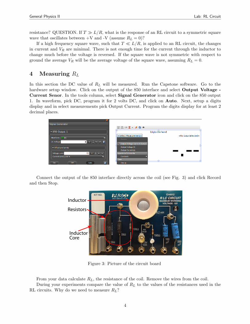
Connect the output of the 850 interface directly across the coil (see Fig. 3) and click Recordand then Stop.
Inductor
InductorCore
Resistors
Figure 3: Picture of the circuit board
From your data calculate RL, the resistance of the coil. Remove the wires from the coil.During your experiments compare the value of RL to the values of the resistances used in the
RL circuits. Why do we need to measure RL?
4
General Physics II Lab: RL Circuit
5 Experiments
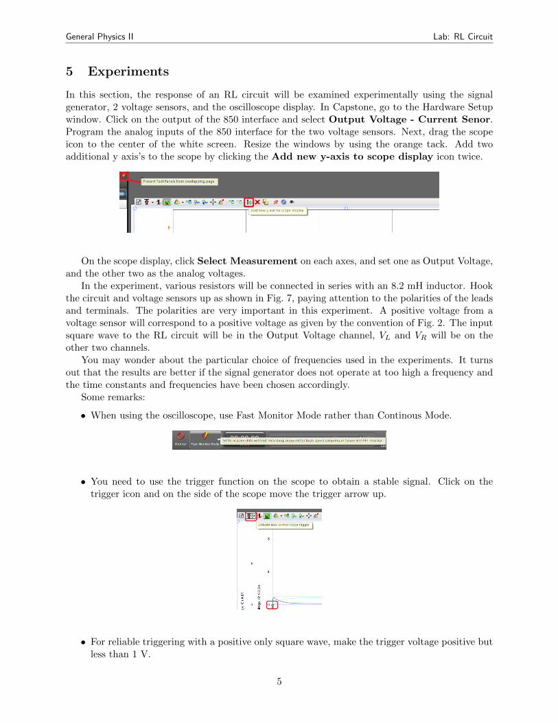
In this section, the response of an RL circuit will be examined experimentally using the signalgenerator, 2 voltage sensors, and the oscilloscope display. In Capstone, go to the Hardware Setupwindow. Click on the output of the 850 interface and select Output Voltage - Current Senor.Program the analog inputs of the 850 interface for the two voltage sensors. Next, drag the scopeicon to the center of the white screen. Resize the windows by using the orange tack. Add twoadditional y axis’s to the scope by clicking the Add new y-axis to scope display icon twice.
On the scope display, click Select Measurement on each axes, and set one as Output Voltage,and the other two as the analog voltages.
In the experiment, various resistors will be connected in series with an 8.2 mH inductor. Hookthe circuit and voltage sensors up as shown in Fig. 7, paying attention to the polarities of the leadsand terminals. The polarities are very important in this experiment. A positive voltage from avoltage sensor will correspond to a positive voltage as given by the convention of Fig. 2. The inputsquare wave to the RL circuit will be in the Output Voltage channel, VL and VR will be on theother two channels.
You may wonder about the particular choice of frequencies used in the experiments. It turnsout that the results are better if the signal generator does not operate at too high a frequency andthe time constants and frequencies have been chosen accordingly.
Some remarks:
• When using the oscilloscope, use Fast Monitor Mode rather than Continous Mode.
• You need to use the trigger function on the scope to obtain a stable signal. Click on thetrigger icon and on the side of the scope move the trigger arrow up.
• For reliable triggering with a positive only square wave, make the trigger voltage positive butless than 1 V.
5
General Physics II Lab: RL Circuit
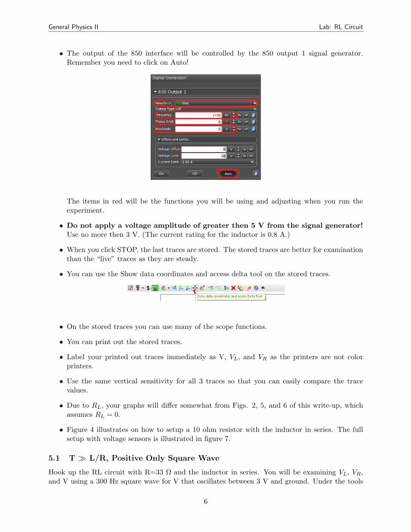
• The output of the 850 interface will be controlled by the 850 output 1 signal generator.Remember you need to click on Auto!
The items in red will be the functions you will be using and adjusting when you run theexperiment.
• Do not apply a voltage amplitude of greater then 5 V from the signal generator!Use no more then 3 V. (The current rating for the inductor is 0.8 A.)
• When you click STOP, the last traces are stored. The stored traces are better for examinationthan the “live” traces as they are steady.
• You can use the Show data coordinates and access delta tool on the stored traces.
• On the stored traces you can use many of the scope functions.
• You can print out the stored traces.
• Label your printed out traces immediately as V, VL, and VR as the printers are not colorprinters.
• Use the same vertical sensitivity for all 3 traces so that you can easily compare the tracevalues.
• Due to RL, your graphs will differ somewhat from Figs. 2, 5, and 6 of this write-up, whichassumes RL = 0.
• Figure 4 illustrates on how to setup a 10 ohm resistor with the inductor in series. The fullsetup with voltage sensors is illustrated in figure 7.
5.1 T L/R, Positive Only Square Wave
Hook up the RL circuit with R=33 Ω and the inductor in series. You will be examining VL, VR,and V using a 300 Hz square wave for V that oscillates between 3 V and ground. Under the tools
6
General Physics II Lab: RL Circuit
column in Capstone, select Signal Generator, and click on 850 Output 1. In waveform, pickPositive Square Wave. Set the frequency ti 300 Hz, the Amplitude to 3 V, and click Auto.Click Monitor and don’t forget to use the trigger on the scope! Click stop. What is the time constantand how does it compare to the period of a 300 Hz square wave? Is there an effect due to RL?Use the Show data coordinates and access delta tool to measure the time constant of theexponentials (1/e=0.37) and compare your measurements to L/R and to L/(R+RL). Which ofthese expressions do you think is the best one to use?
5.2 T L/R, Symmetric Square Wave
Use the same parameters as in section 5.1 except use a square wave that is symmetric with respectto ground. Compare your results to what you expect. Due to limitations in the equipment usedand the non-zero value of RL, the peak voltages will be less than calculated.
5.3 T L/R, Positive Only Square Wave
Apply a 3,000 Hz positive only square wave to an RL circuit with R=10 Ω. What is the timeconstant and how does it compare to T? Compare your results to Fig. 5. In Fig. 5 is approximatingthe exponentials by straight lines reasonable? Note the distortion in the square wave.
5.4 T L/R, Symmetric Square Wave
Use the same parameters as in section 5.3 except use a square wave that is symmetric with respectto ground. Compare to Fig. 6. The effect of RL is quite small here as the average current is small.
5.5 T ≈ L/R, Symmetric Square Wave
Apply a 1100 Hz square wave to an RL circuit with R=10 Ω. Are the results what you expect?Try a lower frequency and a higher frequency. What are the differences in the voltage plots of theinductor and resistor? Why?
6 Finishing Up
Please leave the lab bench as you found it. Thank you.
7

General Physics II Lab: RL Circuit
Figure 4: In this example the resistor is connected in series with inductor and the current is flowingfirst through the resistor then through the inductor.
Figure 5: The signal in the first row is the voltage supply. The signal in the second row is thevoltage across the resistor and in the bottom row is the voltage across the inductor.
8
General Physics II Lab: RL Circuit
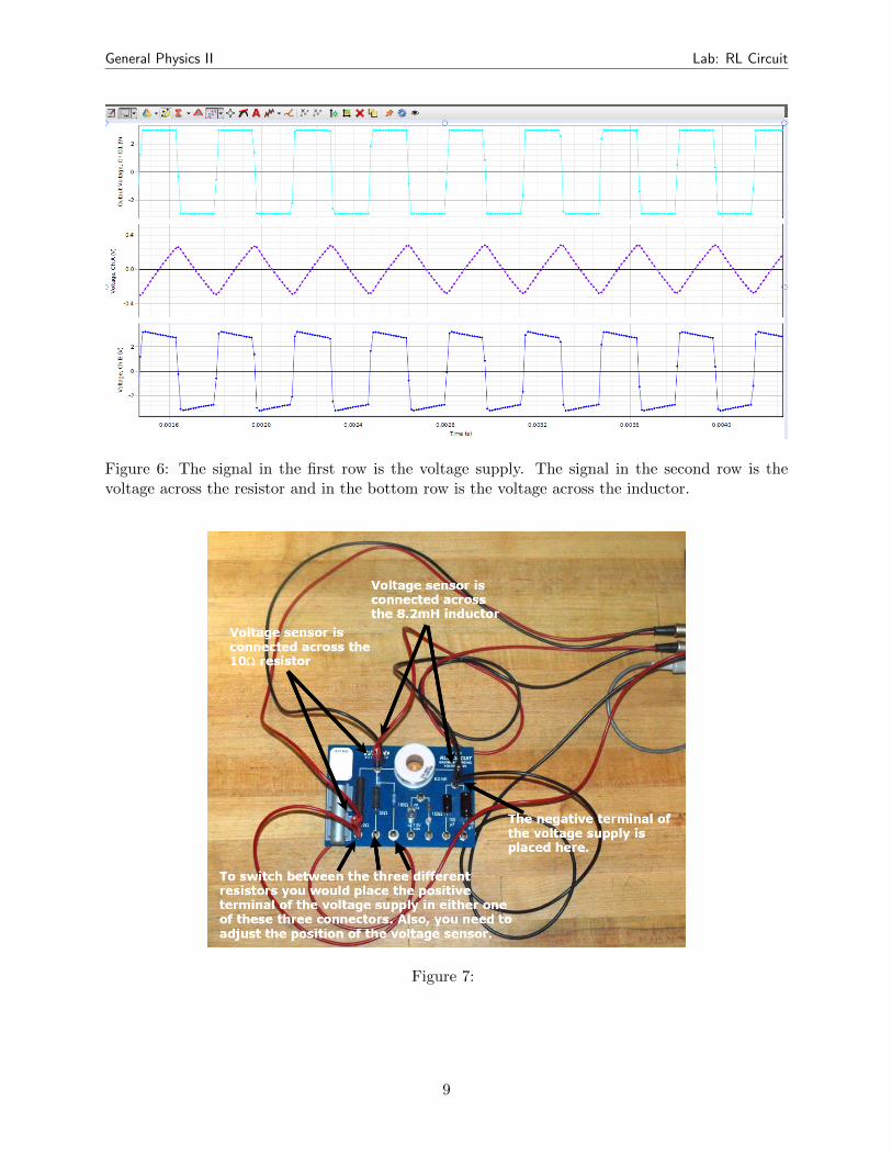
Figure 6: The signal in the first row is the voltage supply. The signal in the second row is thevoltage across the resistor and in the bottom row is the voltage across the inductor.
Figure 7:
9