ripple tank system -...
TRANSCRIPT
www.pasco.com
Waves and Sound – Ripple Tank
286
Ripple Tank SystemWA-9899
Typical Applications:
A Speed of Wave Propagation
A Superposition of Waves
A Effects of Varying Water Depth
A Reflection, Refraction and Diffraction
A Completely Redesigned System
A More Affordable
A Integrated strobe/ripple generator simplifies operation
A Foam “beach” design dramatically reduces reflections from walls
A Silent operation
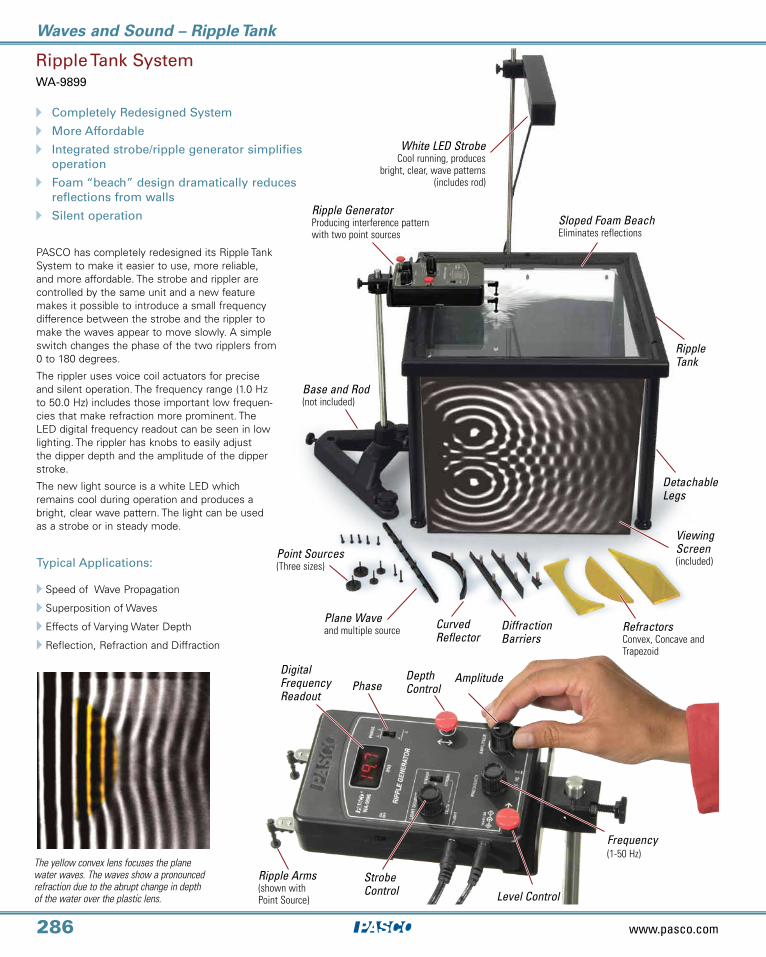
PASCO has completely redesigned its Ripple Tank System to make it easier to use, more reliable, and more affordable. The strobe and rippler are controlled by the same unit and a new feature makes it possible to introduce a small frequency difference between the strobe and the rippler to make the waves appear to move slowly. A simple switch changes the phase of the two ripplers from 0 to 180 degrees.
The rippler uses voice coil actuators for precise and silent operation. The frequency range (1.0 Hz to 50.0 Hz) includes those important low frequen-cies that make refraction more prominent. The LED digital frequency readout can be seen in low lighting. The rippler has knobs to easily adjust the dipper depth and the amplitude of the dipper stroke.
The new light source is a white LED which remains cool during operation and produces a bright, clear wave pattern. The light can be used as a strobe or in steady mode.
The yellow convex lens focuses the plane water waves. The waves show a pronounced refraction due to the abrupt change in depth of the water over the plastic lens.
PhaseDepth Control
Amplitude
Frequency(1-50 Hz)
Level Control
Strobe Control
Digital Frequency Readout
Ripple Arms(shown with Point Source)
White LED StrobeCool running, produces
bright, clear, wave patterns(includes rod)
Ripple GeneratorProducing interference pattern with two point sources
Ripple Tank
Sloped Foam BeachEliminates reflections
Detachable Legs
Viewing Screen(included)
Base and Rod(not included)
Point Sources(Three sizes)
Curved Reflector
RefractorsConvex, Concave and Trapezoid
Diffraction Barriers
Plane Waveand multiple source

Waves and Sound – Ripple Tank
287
Order Information:
Order Information:
Order Information:
Order Information:
Ripple Tank System......................................................................................................................WA-9899
Required:
Large Rod Base .............................................................................................................................ME-8735 p. 212
90 cm Rod ................................................................................................................................................ME-8738 p. 212
Replacement:
Ripple Tank Replacement Set ..........................................................................................WA-9898
Ripple Generator/Light SourceWA-9896
Ripple TankWA-9897
Ripple Tank Replacement SetWA-9898
Ripple Tank .............................................................WA-9897
Includes:Ripple Tank WA-9897 (complete components list at right)Ripple Generator/Light Source WA-9896 (complete components list at right)Water Resistant Storage Box included (64 cm x 52 cm x 17 cm)
Includes:Ripple Generator/Strobe driver with Power AdapterLED Strobe Assembly
Includes:Plastic Storage Box for ComponentsDippersPipetteFoam Beach
Ripple Tank Generator/Light Source .......................WA-9896
Ripple Tank Optics ........................................WA-9898
RefractorsCurved ReflectorDiffraction Barriers
Includes:Tank with legsProjection Mirror and ScreenStrobe Mounting RodRefractors (convex, concave, rhomboid)Curved ReflectorDiffraction Barriers (2 long, 1 short, 1 mini)Plastic Storage Box for components
SurfactantDrainage tube (30 cm) with clamp1 liter Plastic BeakerPipetteClear Plastic RulerWater Resistant Storage Box for Entire System
Plane Wave Generator with multi-point dippersPoint Sources (3 sizes)
Diffraction Barriers are used to create a double slit to show interference. The barriers can be changed to adjust the slit width and slit separation.
The Doppler Effect is clearly demonstrated by moving the dipper. In this picture the
movement is downward.
Specifications Ripple Tank (WA-9897)
Viewing Area: 34 cm x 34 cmUsable Tank Depth: 1 cmDrain Tube: 30 cm longProjection Screen: 35.6 cm x 38.8 cm wideAcrylic Mirror: 49.8 cm x 38.8 cm wideLight Source Support Rod: 46 cm longWater Resistant Storage Box: 64 cm x 52 cm x 17 cm
Specifications Ripple Generator/Light Source (WA-9896)Voice Coil Actuator Frequency Range: 1.0 to 50.0 Hz with 0.1 Hz ResolutionLight Source: Strobe or Steady, 5 W White LEDDigital LED Display: Frequency/DeltaAdjustable Delta Frequency Between Ripple Generator and Strobe: ± 45%frequency setting in steps of 9%Phase Switch: 0 or 180 degreesDepth, Tilt and Amplitude Adjustment ControlsPower Supply: 15 VDC at 1.5 A with On/Off SwitchRippler Case Dimensions: 10.5 cm x 16.3 cm x 3.9 cm
Specifications given at left
Specifications given at left
Specifications given at left
Refraction occurs at the boundaries of this rhomboid shape.

www.pasco.com
Waves and Sound – Mechanical Waves
288
Order Information:
String VibratorWA-9857
A Great Tool for Mechanical Wave Demonstrations
A Uses Magnetic Field to DriveFlexible Tongue
A Includes Constant FrequencyPower Supply
ClampingConvenient for clamping the String Vibrator to the tabletop or any other edge. Holes allow permanent mounting to a surface.
Built-in Rod Clamps
For mounting on either a horizontal
or vertical rod.
Custom Plastic CaseTough enough for
student use; stacking posts allow several
units to be vertically
stacked for storage.
Power InputsDrive String Vibrator’s coil with included power supply, Sine Wave Generator or 750 Interface.
Stainless Steel TongueFlexible metal strip mounted to a powerful neodymium magnet; includes a hole for connecting string or wave cord. Air Vents
Provides good circulation of air around coil.
The String Vibrator transforms mechanical wave demonstrations to hands-on activities that every lab group can easily perform. Featuring an elegant design with no motors or speakers, the String Vibrator allows students to study the fundamental characteristics of mechanical waves including wave speed, frequency, wavelength, amplitude, interference and resonance.
By varying the amplitude and frequency of the AC signal, standing waves are created in the vibrating string.
Powering the String VibratorConstant Frequency Power Supply: Use the included powersupply to create waves at a constant 60 Hz frequency. By changing the tension, various standing wave patterns can be created.
Sine Wave Generator: Use this versatile device to drive the String Vibrator over a range of amplitudes and frequencies (0-800 Hz). A special mode allows the Sine Wave Generator to “learn” the fundamental frequency and scan through each of the resonant frequencies. See page 289 for more details.
750 Interface: The String Vibrator can also be powered by the 750 Interface (CI-7650) directly or by using the Power Amp (CI-6552A).
Includes:String Vibrator UnitConstant Frequency Power Supply (60 Hz)Wave Cord (not shown) (3 meters)
How it WorksA neodymium magnet fastened to the stainless steel tongue is free to move within a coil. By supplying AC current to the coil, an alternat-ing magnetic field is created which vibrates the magnet and tongue.
Typical ApplicationsA Standing Wave Patterns: Students learn about constructive and
destructive interference by studying these waveforms
A Mechanical Wave Characteristics: Wave speed, string density, frequency, amplitude and wavelength can all be examined
Power the String Vibrator by plugging the included power supply into the wall outlet. The waveform is varied by changing the tension in the elastic Wave Cord.
String Vibrator ...........................................................................................................WA-9857 Recommended:Sine Wave Generator........................................................................................WA-9867
Waves and Sound – Mechanical Waves
289
Order Information:
Sine Wave GeneratorWA-9867
A Sine Wave Output up to 800 Hz
A Ideal for Driving Speakers and Wave Drivers
A Auto-Scan of Resonant Frequencies
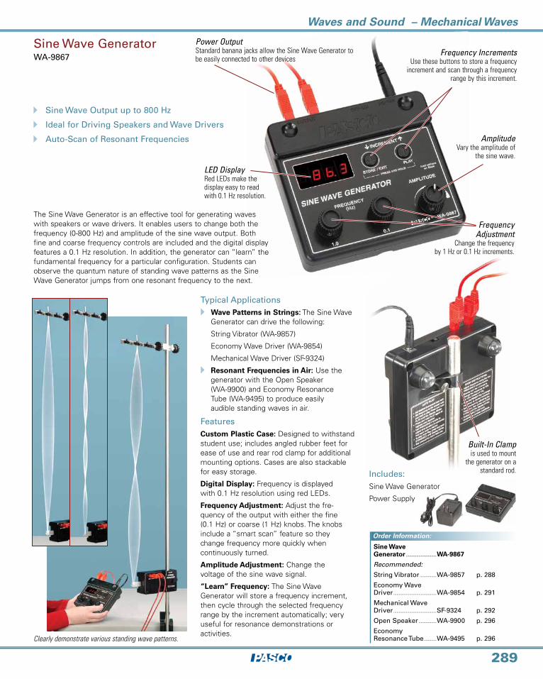
The Sine Wave Generator is an effective tool for generating waves with speakers or wave drivers. It enables users to change both the frequency (0-800 Hz) and amplitude of the sine wave output. Both fine and coarse frequency controls are included and the digital display features a 0.1 Hz resolution. In addition, the generator can “learn” the fundamental frequency for a particular configuration. Students can observe the quantum nature of standing wave patterns as the Sine Wave Generator jumps from one resonant frequency to the next.
Typical ApplicationsA Wave Patterns in Strings: The Sine Wave
Generator can drive the following:
String Vibrator (WA-9857)
Economy Wave Driver (WA-9854)
Mechanical Wave Driver (SF-9324)
A Resonant Frequencies in Air: Use the generator with the Open Speaker (WA-9900) and Economy Resonance Tube (WA-9495) to produce easily audible standing waves in air.
FeaturesCustom Plastic Case: Designed to withstand student use; includes angled rubber feet for ease of use and rear rod clamp for additional mounting options. Cases are also stackable for easy storage.
Digital Display: Frequency is displayed with 0.1 Hz resolution using red LEDs.
Frequency Adjustment: Adjust the fre-quency of the output with either the fine (0.1 Hz) or coarse (1 Hz) knobs. The knobs include a “smart scan” feature so they change frequency more quickly when continuously turned.
Amplitude Adjustment: Change the voltage of the sine wave signal.
“Learn” Frequency: The Sine Wave Generator will store a frequency increment, then cycle through the selected frequency range by the increment automatically; very useful for resonance demonstrations or activities.
LED DisplayRed LEDs make the display easy to read with 0.1 Hz resolution.
Power OutputStandard banana jacks allow the Sine Wave Generator to be easily connected to other devices
Frequency IncrementsUse these buttons to store a frequency
increment and scan through a frequency range by this increment.
Frequency Adjustment
Change the frequency by 1 Hz or 0.1 Hz increments.
AmplitudeVary the amplitude of
the sine wave.
Built-In Clampis used to mount
the generator on a standard rod.
Clearly demonstrate various standing wave patterns.
Includes:Sine Wave Generator
Power Supply
Sine Wave Generator .............................WA-9867
Recommended:
String Vibrator ................WA-9857 p. 288
Economy Wave Driver .........................................WA-9854 p. 291
Mechanical Wave Driver .........................................SF-9324 p. 292
Open Speaker .................WA-9900 p. 296
Economy Resonance Tube ............WA-9495 p. 296

www.pasco.com
Waves and Sound – Mechanical Waves
290
Includes:Control Box and one Strobe Module
A 1 Hz to 500 HzA Variable IntensityA Low Cost
Visualize motion with PASCO’s NEW modular LED Strobe.
Strobe.....................................................................................................................ME-6978. .(Includes Control Box and one Strobe Module)
Additional Strobe Module ...........................................................ME-6982
Shown in use with:
String Vibrator .............................................................................................WA-9857 p. 288
Small “A” Base ............................................................................................ME-8976 p. 212
Large Rod Base ..........................................................................................ME-8735 p. 212
60 cm long Steel Rod (threaded) ....................................ME-8977 p. 212
90 cm long Steel Rod (non-threaded) .......................ME-8738 p. 212
Pendulum Clamp ...................................................................................SE-9443 p. 214
Shown using ME-6978 Strobe (with Strobe Module) and three additional ME-6982 Strobe Modules.
WA-9857 String Vibrator includes a constant frequency (60 Hz) brick power supply. Can also be used with the WA-9867 Sine Wave Generator to vary the amplitude and frequency.
StrobeME-6978
Specifications:
Frequency.Range: 1 Hz to 500 HzResolution: 0.1 HzAccuracy: 0.1%Lamp.Life: 50,000 hours.Brightness:.230 lumens (peak) per module
Unique modular design makes it easy to light any geometry. The ME-6978 Strobe includes the Strobe Control Box and one Strobe Module. Additional Strobe Modules (ME-6982) can be purchased separately (see below) for up to a total of four lamp modules per controller, and multiple control boxes can be connected together using the External Trigger. The Strobe Modules have a tilting lamp head on a sturdy base that sits on the table or fastens to a rod stand.
FeaturesDisplay frequency in Hz or rpm
Adjustable light intensity
External Trigger to Daisy-chain multiple controllers together
Trigger strobe using external input such as the ME-9498A photogate.
Frequency Adjustment
Digital Display
Lamp ON/OFF
Tilting lamp head on a sturdy base sits on the table or fastens to a rod stand.
Brightness Control
Order Information:
Waves and Sound – Mechanical Waves
291
Order Information:Order Information:
Order Information:
Economy Wave DriverWA-9854
A Economical Tool for the Study of Mechanical Waves
A Includes Constant Frequency Power Supply
A Can Also be Driven with PASCO’s Sine Wave Generator or 750 Interface
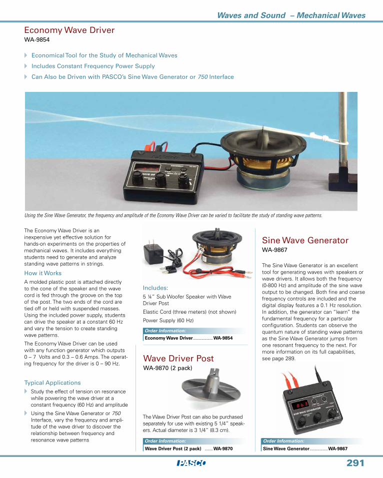
Using the Sine Wave Generator, the frequency and amplitude of the Economy Wave Driver can be varied to facilitate the study of standing wave patterns.
Includes:5 ¼” Sub Woofer Speaker with Wave Driver Post
Elastic Cord (three meters) (not shown)
Power Supply (60 Hz)
Sine Wave GeneratorWA-9867
The Sine Wave Generator is an excellent tool for generating waves with speakers or wave drivers. It allows both the frequency (0-800 Hz) and amplitude of the sine wave output to be changed. Both fine and coarse frequency controls are included and the digital display features a 0.1 Hz resolution. In addition, the generator can “learn” the fundamental frequency for a particular configuration. Students can observe the quantum nature of standing wave patterns as the Sine Wave Generator jumps from one resonant frequency to the next. For more information on its full capabilities, see page 289.
The Economy Wave Driver is an inexpensive yet effective solution for hands-on experiments on the properties of mechanical waves. It includes everything students need to generate and analyze standing wave patterns in strings.
How it WorksA molded plastic post is attached directly to the cone of the speaker and the wave cord is fed through the groove on the top of the post. The two ends of the cord are tied off or held with suspended masses. Using the included power supply, students can drive the speaker at a constant 60 Hz and vary the tension to create standing wave patterns.
The Economy Wave Driver can be used with any function generator which outputs 0 – 7 Volts and 0.3 – 0.6 Amps. The operat-ing frequency for the driver is 0 – 90 Hz.
Typical ApplicationsA Study the effect of tension on resonance
while powering the wave driver at a constant frequency (60 Hz) and amplitude
A Using the Sine Wave Generator or 750 Interface, vary the frequency and ampli-tude of the wave driver to discover the relationship between frequency and resonance wave patterns
The Wave Driver Post can also be purchased separately for use with existing 5 1/4” speak-ers. Actual diameter is 3 1/4” (8.3 cm).
Wave Driver Post WA-9870 (2 pack)
Sine.Wave.Generator..........................WA-9867.
Economy.Wave.Driver............................WA-9854.
Wave.Driver.Post.(2.pack)..............WA-9870.
www.pasco.com
Waves and Sound – Mechanical Waves
292
Order Information:
Mechanical Wave Driver Accessories
Chladni Plates KitWA-9607
In the early nineteenth century, Ernst Chladni added another dimension to wave experiments by sprinkling sand on a thin plate and using a violin bow to induce vibrations. The sand collected along the nodal lines of the wave patterns painted clear and beautiful pictures of the various modes of vibration.
The Chladni Plates Kit and a Wave Driver allow continuous vibrations to be produced at measurable frequencies. Students can determine the resonant frequencies of the plates and examine the modes of vibration at any frequency.
The Chladni Plates Kit includes a 24 cm x 24 cm square plate, round plate, 0.8 kg of extra-fine sand and a sand shaker. The round plate can be vibrated about its center or an offset point to investigate both symmetric and asymmetric modes of vibration.
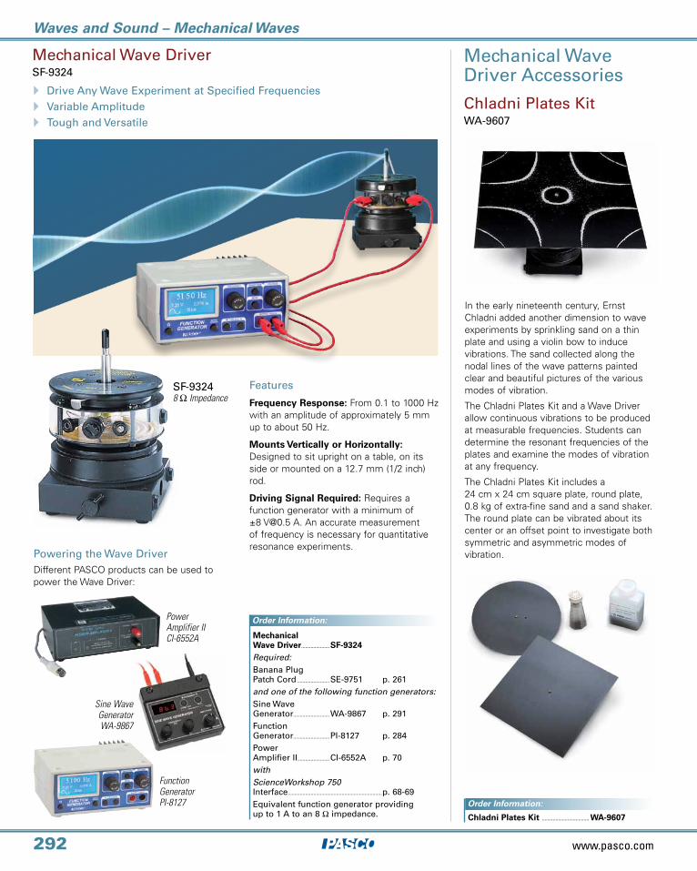
Mechanical Wave DriverSF-9324
SF-9324 8 Ω Impedance
Mechanical Wave Driver .....................SF-9324 Required:Banana Plug Patch Cord ........................SE-9751 p. 261 and one of the following function generators:Sine Wave Generator...........................WA-9867 p. 291 Function Generator...........................PI-8127 p. 284 Power Amplifier II........................CI-6552A p. 70 withScienceWorkshop 750 Interface ......................................................................p. 68-69Equivalent function generator providing up to 1 A to an 8 Ω impedance.
Power Amplifier II CI-6552A
Sine Wave Generator WA-9867
Powering the Wave DriverDifferent PASCO products can be used to power the Wave Driver:
Order Information:
Chladni Plates Kit ................................... WA-9607
A Drive Any Wave Experiment at Specified FrequenciesA Variable AmplitudeA Tough and Versatile
Function Generator PI-8127
Features
Frequency Response: From 0.1 to 1000 Hz with an amplitude of approximately 5 mm up to about 50 Hz.
Mounts Vertically or Horizontally: Designed to sit upright on a table, on its side or mounted on a 12.7 mm (1/2 inch) rod.
Driving Signal Required: Requires afunction generator with a minimum of ±8 [email protected] A. An accurate measurement of frequency is necessary for quantitative resonance experiments.
Waves and Sound – Mechanical Waves
293
String HoldersSlot (set of 4) SF-9322
Mechanical Wave Driver Accessories
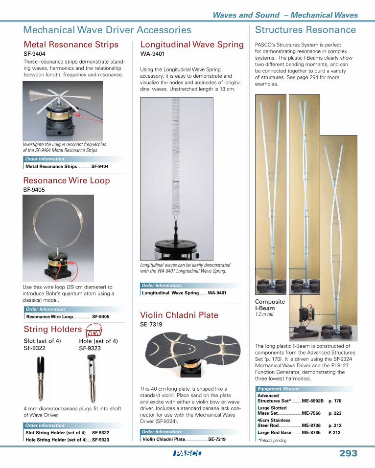
Investigate the unique resonant frequencies of the SF-9404 Metal Resonance Strips.
Metal Resonance StripsSF-9404
Longitudinal Wave SpringWA-9401
Longitudinal waves can be easily demonstrated with the WA-9401 Longitudinal Wave Spring.
Resonance Wire LoopSF-9405
Violin Chladni PlateSE-7319
This 40 cm-long plate is shaped like a standard violin. Place sand on the plate and excite with either a violin bow or wave driver. Includes a standard banana jack con-nector for use with the Mechanical Wave Driver (SF-9324).
Using the Longitudinal Wave Spring accessory, it is easy to demonstrate and visualize the nodes and antinodes of longitu-dinal waves. Unstretched length is 13 cm.
These resonance strips demonstrate stand-ing waves, harmonics and the relationship between length, frequency and resonance.
Use this wire loop (29 cm diameter) to introduce Bohr’s quantum atom using a classical model.
Metal Resonance Strips ................. SF-9404
Resonance Wire Loop ......................... SF-9405
Longitudinal Wave Spring ........... WA-9401
Violin Chladni Plate ............................... SE-7319
Order Information:
Order Information:
Order Information:
Equipment Shown:
Order Information:
Advanced Structures Set* ..............ME-6992B p. 170
Large Slotted Mass Set .................................ME-7566 p. 223
45cm Stainless Steel Rod................................ME-8736 p. 212
Large Rod Base ..............ME-8735 P. 212
Structures Resonance
Composite I-Beam 1.2 m tall
PASCO’s Structures System is perfect for demonstrating resonance in complex systems. The plastic I-Beams clearly show two different bending moments, and can be connected together to build a variety of structures. See page 294 for more examples.
The long plastic I-Beam is constructed of components from the Advanced Structures Set (p. 170). It is driven using the SF-9324 Mechanical Wave Driver and the PI-8127 Function Generator, demonstrating the three lowest harmonics.
*Patents pending
Order Information:
4 mm diameter banana plugs fit into shaft of Wave Driver.
Slot String Holder (set of 4) ........ SF-9322
Hole String Holder (set of 4) ...... SF-9323
Hole (set of 4)SF-9323

www.pasco.com
Waves and Sound – Resonance
294
Experiments on this page shown in use with:
Advanced Structures Set* ..............................ME-6992B p. 172 Load Cell Amplifier* ...............................................PS-2198 p. 32 5 N Load Cell* ................................................................PS-2201 p. 33 Function Generator ..................................................PI-8127 p. 284 Mechanical Wave Driver ....................................SF-9324 p. 292 Mass and Hanger Set............................................ME-8979 p. 223 Short Slotted Mass Set .......................................ME-7589 p. 223 Rods and Stands ........................................................................................................p. 212
This building frame is built with an Advanced Structures Set. The building is being shaken with the Mechanical Wave Driver. Additional mass is added to the foam core floors (not included). See page 184 for an example of passive pendulum damping with the shaking tower.
The bridge shown here was constructed using the Advanced Structures Set (pages 170-171), plus additional Truss Sets (page 168). The bridge is driven using the SF -9324 Mechanical Wave Driver and the PI-8127 Function Generator.
Tied Arch Bridge2 m long
Demonstrate resonance in complex systems.
Function Generator (PI-8127)
Mechanical Wave Driver (SF-9324)
Load Cell Amplifier (PS-2198)
Short Slotted Mass Set (ME-7589)
Students can analyze phase relationship between the driving force (blue trace)
and resulting acceleration of the bridge (red trace).
Shaking Tower75 cm tall
5N Load Cell
*Patents pending
The resonance of the bridge is characterized by driving the bridge at different frequencies, and measuring the resulting accelerations using Load Cells at vari-ous locations. The graph above (orange trace) shows the response in the 1 Hz to 10 Hz frequency range. The students can also look at the free vibration of the bridge by simply hitting it with a hammer! The resulting FFT (blue trace) shows the correlation between the forced and free vibrations.
Measure acceleration with a 5N Load CellConnect one end of a load cell to the structure and attach a mass to the other end of the load cell. The acceleration of the structure is graphed in real time as the structure shakes.
Waves and Sound – Mechanical Waves
295
Order Information:
A Investigate Waves on a Wire
A Control Length, Tension, Density and Driving Frequency
A Observe and Measure the Waveforms on an Oscilloscope
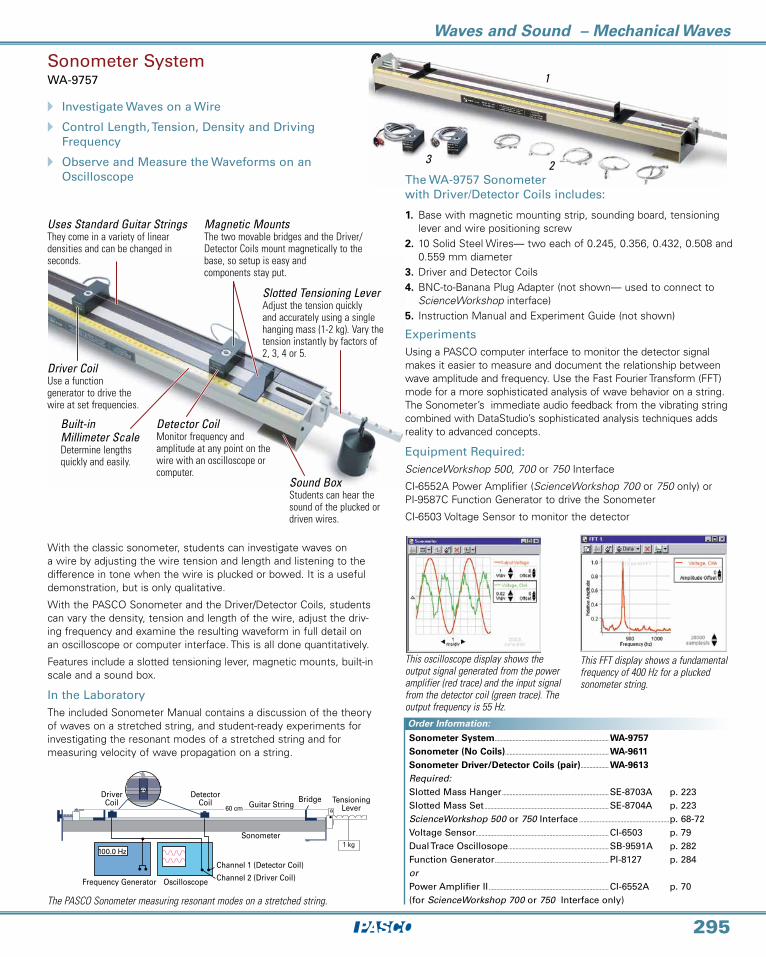
Driver Coil Use a function generator to drive the wire at set frequencies.
Built-in Millimeter Scale Determine lengths quickly and easily.
Detector CoilMonitor frequency and amplitude at any point on the wire with an oscilloscope or computer.
Sound BoxStudents can hear the sound of the plucked or driven wires.
Slotted Tensioning LeverAdjust the tension quickly and accurately using a single hanging mass (1-2 kg). Vary the tension instantly by factors of 2, 3, 4 or 5.
Magnetic Mounts The two movable bridges and the Driver/Detector Coils mount magnetically to the base, so setup is easy and components stay put.
Uses Standard Guitar Strings They come in a variety of linear densities and can be changed in seconds.
100.0 Hz
Frequency Generator Oscilloscope Channel 2 (Driver Coil)
Channel 1 (Detector Coil)
Driver Coil
Detector Coil Guitar String
Bridge Tensioning Lever
Sonometer
60 cm
1 kg
Sonometer SystemWA-9757
With the classic sonometer, students can investigate waves on a wire by adjusting the wire tension and length and listening to the difference in tone when the wire is plucked or bowed. It is a useful demonstration, but is only qualitative.
With the PASCO Sonometer and the Driver/Detector Coils, students can vary the density, tension and length of the wire, adjust the driv-ing frequency and examine the resulting waveform in full detail on an oscilloscope or computer interface. This is all done quantitatively.
Features include a slotted tensioning lever, magnetic mounts, built-in scale and a sound box.
In the LaboratoryThe included Sonometer Manual contains a discussion of the theory of waves on a stretched string, and student-ready experiments for investigating the resonant modes of a stretched string and for measuring velocity of wave propagation on a string.
The PASCO Sonometer measuring resonant modes on a stretched string.
This FFT display shows a fundamental frequency of 400 Hz for a plucked sonometer string.
This oscilloscope display shows the output signal generated from the power amplifier (red trace) and the input signal from the detector coil (green trace). The output frequency is 55 Hz.
ExperimentsUsing a PASCO computer interface to monitor the detector signal makes it easier to measure and document the relationship be tween wave amplitude and frequency. Use the Fast Fourier Transform (FFT) mode for a more sophisticated analysis of wave behavior on a string. The Sonometer’s immediate audio feedback from the vibrating string combined with DataStudio’s sophisticated analysis tech niques adds reality to advanced concepts.
Equipment Required:ScienceWorkshop 500, 700 or 750 Interface
CI-6552A Power Amplifier (ScienceWorkshop 700 or 750 only) or PI-9587C Function Generator to drive the Sonometer
CI-6503 Voltage Sensor to monitor the detector
1
3 2
1. Base with magnetic mounting strip, sounding board, tensioning lever and wire positioning screw
2. 10 Solid Steel Wires— two each of 0.245, 0.356, 0.432, 0.508 and 0.559 mm diameter
3. Driver and Detector Coils4. BNC-to-Banana Plug Adapter (not shown— used to connect to
ScienceWorkshop interface)5. Instruction Manual and Experiment Guide (not shown)
The WA-9757 Sonometer with Driver/Detector Coils includes:
Sonometer System ............................................................................. WA-9757 Sonometer (No Coils) ...................................................................... WA-9611 Sonometer Driver/Detector Coils (pair) ................... WA-9613 Required:Slotted Mass Hanger ........................................................................ SE-8703A p. 223 Slotted Mass Set .................................................................................... SE-8704A p. 223 ScienceWorkshop 500 or 750 Interface .............................................................p. 68-72Voltage Sensor.......................................................................................... CI-6503 p. 79 Dual Trace Oscillosope .................................................................... SB-9591A p. 282 Function Generator ............................................................................. PI-8127 p. 284 orPower Amplifier II ................................................................................. CI-6552A p. 70 (for ScienceWorkshop 700 or 750 Interface only)

www.pasco.com
Waves and Sound – Sound
296
SpecificationsFrequency Response: 75 - 8000 HzImpedance: 8 ohmsInput Power: 60 watts (max)
Open SpeakerWA-9900
Economy Resonance TubeWA-9495
Features a high-quality, 13.3 cm woofer mounted on a sturdy base with standard banana jack inputs. The Open Speaker is not enclosed inside a case, making it perfect for resonance experiments.
Students will have no difficulty hearing resonant frequencies from this tube. Two nested cardboard tubes allow the length of the air column to be easily varied, and the inner tube contains a removable end-cap to change from a “closed” to an “open” tube. The length of the resonating column can be read directly off the metric scale for both open and closed operation.
WA-9495 Includes:Outer Tube (length 1.3m; diameter 0.15m)
Inner Tube (Includes measuring tape and removable end-cap)
Tube Stands (2)
Economy Resonance Tube ...................................WA-9495
Shown in use with:
Open Speaker ......................................................................WA-9900
Sine Wave Generator..................................................WA-9867 p. 289
Nested Tubes
The removable end-cap on the inner tube allows the air column to act as either an “open” or a “closed” tube.
Closed tube (with end cap in place)
Open tube (with end cap removed)
Shown in use with the Open Speaker (WA-9900) and the Sine Wave Generator (WA-9867)
Metric Scale Directly measures
length of air column for open and closed tube.
Stand
Demonstrate Acoustic Resonance
Order Information:
Order Information:
Open Speaker .......................................................................................................WA-9900

Waves and Sound – Sound
297
Resonance TubeWA-9612
A Investigate Sound Waves in a Closed or Open Tube
A Observe Waveforms on an Oscilloscope
A Movable Piston and Microphone
Movable piston
Microphone on probe rod
This Resonance Tube brings the same advantages to longitudinal wave experiments that PASCO’s Sonometer brings to transverse wave experiments. Drive the speaker with a function generator to create stable wave patterns at specified frequencies. Then connect an oscilloscope or ScienceWorkshop computer interface to the microphone to examine the waveforms in detail. The 90 cm long, clear plastic tube is simple and rugged.
Built-in Metric ScaleMakes it easy to measure tube length and microphone position.
Movable MicrophonePosition the microphone at the edge of the tube or use the probe to position it anywhere inside the tube. Easily locate all the nodes and antinodes of a stand-ing wave pattern.
Musical Instrument HolesA pair of holes in the tube let students investigate the effects of closed and open holes in musical instruments. When performing other experiments, the holes can be covered with the included slip rings.
Built-in Speaker/ Microphone AssemblySetup is easy. A function generator is used to drive the speaker.
Movable PistonPush in the piston to adjust the tube length.
Two methods of investigating wave patterns:
with a movable piston and fixed microphone...
with a fixed piston and movable microphone.
Includes:1. 90 cm Acrylic Tube with mounting stand and built-in
millimeter scale
2. Piston and Rod for adjusting tube length
3. Miniature Microphone
4. Microphone Probe Rod for examining the waveform inside the tube
5. Speaker Assembly
6. Two holes with slip ring covers
7. BNC-to-Banana Plug Adapter (not shown— used to connect to ScienceWorkshop interface)
8. Instruction Manual and Experiment Guide (not shown)
This DataStudio FFT display shows the
frequency spectrum for a sound above 600
Hz recorded by the Resonance Tube’s
microphone.
The oscilloscope display shows two traces: the green trace is the output signal from the Resonance Tube’s microphone, and the red trace is the output signal from DataStudio’s Signal Generator.
Equipment Required:ScienceWorkshop 700 or 750 Interface
CI-6552A Power Amplifier (ScienceWorkshop 700 or 750 only) orPI-9587C Function Generator to drive the Resonance Tube
CI-6503 Voltage Sensor to monitor the detector
Resonance Tube ....................................................................................... WA-9612 Required for use with ScienceWorkshop:ScienceWorkshop 750 Interface ..................................................................................p. 68-72Voltage Sensor.......................................................................................... CI-6503 p. 79 Power Amplifier II ................................................................................. CI-6552A p. 70 (for ScienceWorkshop 700 or 750 Interface only)Required for use without sensors:20 MHz Dual Trace Oscilloscope ........................................ SB-9591A p. 282 Function Generator ............................................................................. PI-8127 p. 284 Replacement Supplies:Replacement Speaker ...................................................................... WA-9662
Order Information:

www.pasco.com
Waves and Sound – Transverse Waves
298
Complete Wave Motion Demonstrator SE-9600
SE-9600 Complete Wave Motion Demonstrator: in three sections. The high-amplitude, slow-moving waves provide a fascinating introduction to basic wave phenomena. The SE-9601 Single Section Wave Motion Demonstrator:
A-frame design collapses for easy storage.
Single Section Wave Motion Demonstrator SE-9601
A Produces Slow-Moving, High-Amplitude Transverse WavesA Demonstrates All Basic Wave Phenomena
The PASCO SE-9600 Complete (Transverse) Wave Motion Demonstrator allows mechani-cal waves to be created to demonstrate the behavior and properties common to many types of waves.
How It WorksA series of steel rods is attached at their centers to a torsion wire. When a rod is displaced and released, a wave propagates along the rod. Velocity depends on the torsion constant of the wire and the moment of inertia of the rods.
Features2.3 Meters Long: Plenty of room to watch the wave develop and interact.
Three Wave Sections: Each section has rods of different lengths, allowing reflection and transmission demonstrations.
- Section 1 is 92 cm long with 46 cm rods.
- Section 2 is 92 cm long with 23 cm rods. The resulting wave velocity is about three times as fast.
- Section 3 is 46 cm long with rods that vary exponentially from 46 cm to 23 cm. This section acts as an impedance-matching unit.
Yellow Rod Tips: Easy viewing and high-lights wave motion.
Folds for Compact Storage
Easy Setup
Matter ModelME-9825A
Transverse Waves
Longitudinal Waves
Includes:Atoms (40)Heavy springs (60) (350 N/m spring constant)Light springs (60) (70 N/m spring constant)Long Springs (60)Nuts (30) (for increasing the atom mass)Brass rod (1)
A Dynamic Model of Solid Materials
A Excellent Visualization of Wave Motion
A Easily Assembled into a Variety of Configurations
Students can investigate wave properties including reflection, wave speed, and standing waves. See page 204 for more information on Matter Model.
Complete Wave Motion Demonstrator ..........................SE-9600
Single Section Wave Motion Demonstrator ..........................SE-9601
Matter Model .............................................ME-9825A
Includes:Section 1 (46 cm long rods)
Length of section: 92 cm
Clamp for rigid termination
Dash Pot for liquid damping
Order Information:
Order Information:Order Information:
Waves and Sound – Wave Media
299
Single Section Wave Motion Demonstrator SE-9601
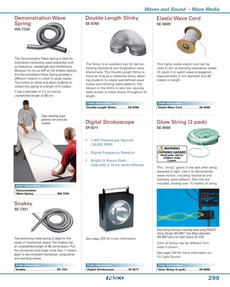
Double-Length SlinkySE-8760
The extra-long metal spring is ideal for the study of mechanical waves. The Snakey has an unstretched length of 80 centimeters. Pull the convenient end loops more than 7 meters apart to demonstrate transverse, longitudinal and standing waves.
Demonstration Wave SpringWA-7334
The Demonstration Wave Spring is ideal for illustrating mechanical wave properties such as frequency, wavelength and interference. Because it’s not as stiff as the Snakey (below), the Demonstration Wave Spring provides a different medium in which to study waves. Two hooks on either end allow students to stretch this spring to a length of 8 meters.
It has a diameter of 2.3 cm and an unstretched length of 80 cm.
SnakeySE-7331
Clear standing wave patterns can easily be created.
The Slinky is an excellent tool for demon-strating transverse and longitudinal wave phenomena. This Double-Length Slinky is twice as long as a traditional slinky, allow-ing students to create well-defined wave pulses and standing wave patterns. The tension in the Slinky is very low, causing wave pulses to travel slowly throughout its length.
Elastic Wave Cord.......................................SE-9409
Glow String (2 pack) ..............................SE-8690
Elastic Wave CordSE-9409
Glow String (2 pack)SE-8690
Glow String forming a standing wave using PASCO’s String Vibrator WA-9857, Sine Wave Generator WA-9867 and a UV Light Source SE-7228.
Digital StroboscopeSF-9211
A 1-300 Flashes per Second
(18,000 RPM)
A Digital Frequency Readout
A Bright: A Xenon flashtube with a 14 cm wide reflector
See page 225 for more information.
Digital Stroboscope ................................SF-9211
This highly visible elastic cord can be used to set up standing transverse waves. Or, pluck it to watch wave propagation. Approximately 3 mm diameter and 90 meters in length.
Color of string may be different from what is shown.
See page 334 for more information on UV Light Source.
Demonstration Wave Spring ......................................................WA-7334
Double-Length Slinky ...........................SE-8760
This “string” glows in the dark after being exposed to light. Use it to demonstrate wave motion, including resonance and standing wave patterns. Two rolls are included, totaling over 15 meters of string.
Order Information:
Order Information:
Order Information:
Order Information: Order Information:
Order Information:
Snakey ......................................................................SE-7331
www.pasco.com
Waves and Sound – WAVEPORT
300
Order Information:
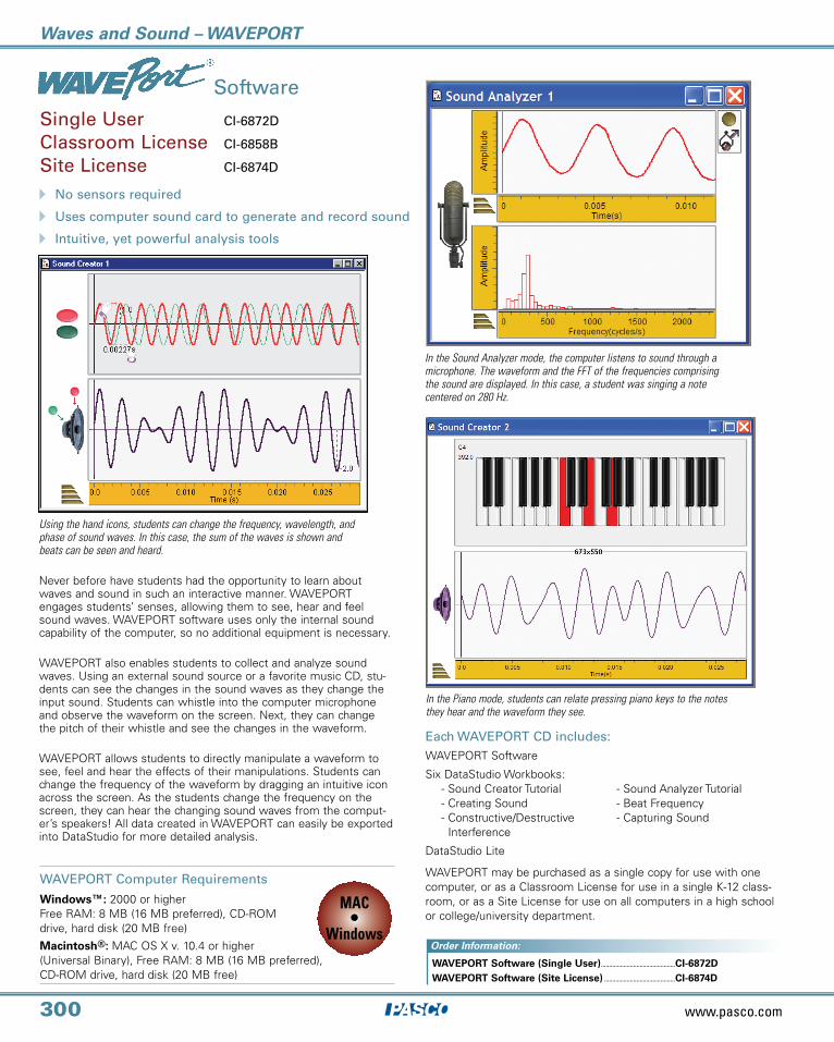
Never before have students had the opportunity to learn about waves and sound in such an interactive manner. WAVEPORT engages students’ senses, allowing them to see, hear and feel sound waves. WAVEPORT software uses only the internal sound capability of the computer, so no additional equipment is necessary.
WAVEPORT also enables students to collect and analyze sound waves. Using an external sound source or a favorite music CD, stu-dents can see the changes in the sound waves as they change the input sound. Students can whistle into the computer microphone and observe the waveform on the screen. Next, they can change the pitch of their whistle and see the changes in the waveform.
WAVEPORT allows students to directly manipulate a waveform to see, feel and hear the effects of their manipulations. Students can change the frequency of the waveform by dragging an intuitive icon across the screen. As the students change the frequency on the screen, they can hear the changing sound waves from the comput-er’s speakers! All data created in WAVEPORT can easily be exported into DataStudio for more detailed analysis.
Software
Each WAVEPORT CD includes:WAVEPORT Software
Six DataStudio Workbooks: - Sound Creator Tutorial - Sound Analyzer Tutorial - Creating Sound - Beat Frequency - Constructive/Destructive - Capturing Sound
Interference
DataStudio Lite
A No sensors required
A Uses computer sound card to generate and record sound
A Intuitive, yet powerful analysis tools
Single User CI-6872D
Classroom License CI-6858B
Site License CI-6874D
WAVEPORT may be purchased as a single copy for use with one computer, or as a Classroom License for use in a single K-12 class-room, or as a Site License for use on all computers in a high school or college/university department.
Using the hand icons, students can change the frequency, wavelength, and phase of sound waves. In this case, the sum of the waves is shown and beats can be seen and heard.
In the Piano mode, students can relate pressing piano keys to the notes they hear and the waveform they see.
In the Sound Analyzer mode, the computer listens to sound through a microphone. The waveform and the FFT of the frequencies comprising the sound are displayed. In this case, a student was singing a note centered on 280 Hz.
WAVEPORT Software (Single User) ..............................................CI-6872D WAVEPORT Software (Site License) ............................................CI-6874D
MAC•
Windows
WAVEPORT Computer Requirements
Windows™: 2000 or higherFree RAM: 8 MB (16 MB preferred), CD-ROM drive, hard disk (20 MB free)
Macintosh®: MAC OS X v. 10.4 or higher (Universal Binary), Free RAM: 8 MB (16 MB preferred), CD-ROM drive, hard disk (20 MB free)
Waves and Sound – Doppler
301
Order Information:
O-rings Remove easily to change battery
Skinned Foam BodyProtects buzzer during impact
Rope TubePass rope through to fly horizontally
The Doppler Rocket combines the elements of a toy with an audio Doppler shift to create an educational experience students won’t forget. The Doppler Rocket emits a true, sinusoidal sound waveform at a constant frequency of approximately 620 Hz. The circuit and speaker are housed in skinned foam that protect the unit during normal impacts. The circuit is powered by a 9V battery. As the Doppler Rocket passes the students, they hear a noticeable shift in frequency. Velocities of 10 m/s can be easily achieved, resulting in a 20 Hz shift in frequency.
A Experience the Frequency Shift of Sound Waves
A Easily Generate High Velocity Motion A Rugged Construction
Doppler RocketWA-9826
Flying Horizontally — A set of two ropes can be passed through the center of the unit. This allows students to use the included handles to propel the Doppler Rocket across the room at high velocities. The unit is guided by the ropes. Students hear the change in pitch as the Doppler Rocket flies past them.
Includes:Doppler RocketRope (30 meters)Handles (4)Handle Cushions (4)Battery (9 Volt)
Doppler Rocket.........................................................................................................WA-9826
Ripple Tank SystemWA-9899
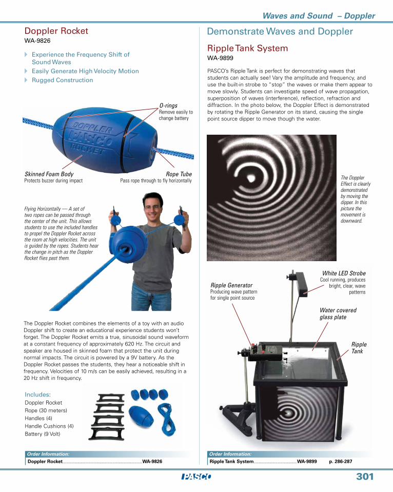
The Doppler Effect is clearly demonstrated by moving the dipper. In this picture the movement is downward.
Demonstrate Waves and Doppler
PASCO’s Ripple Tank is perfect for demonstrating waves that students can actually see! Vary the amplitude and frequency, and use the built-in strobe to “stop” the waves or make them appear to move slowly. Students can investigate speed of wave propagation, superposition of waves (interference), reflection, refraction and diffraction. In the photo below, the Doppler Effect is demonstrated by rotating the Ripple Generator on its stand, causing the single point source dipper to move though the water.
White LED StrobeCool running, produces
bright, clear, wave patterns
Ripple GeneratorProducing wave pattern for single point source
Ripple Tank
Water covered glass plate
Order Information:
Ripple Tank System.........................................................WA-9899 p. 286-287

www.pasco.com
Waves and Sound – Tuning Forks
302
(b)
(a)
Chime SetSE-9081
The Chime Set features three chimes which produce easily heard tones at 1750, 2650 and 3500 Hz. The highest frequency chime is one octave above the lowest frequency chime. Use WAVEPORT software to analyze the sound waves from the Chime Set. Length of bars (1.2 cm diameter): 17.7 cm, 14.4 cm, 12.4 cm.
Tuning Fork SetSE-7342
The tuning fork has long been the tool of choice for helping students understand the relationship between wave frequency and pitch. These high-quality aluminum tuning forks are both rugged and economical. The set includes eight forks representing a full octave of frequencies, a soft protective case and a rubber mallet.
Sympathetic Resonance Box SetHardwood resonance box with a 256 Hz A4 tuning fork (a)
Hardwood resonance box with an adjustable tuning fork (b)
Resonance Box (Single)Hardwood resonance box with a 256 Hz A4 tuning fork (a)
Resonance Boxes
Resonance boxes are great instruments for amplifying sound from a tuning fork. These boxes are constructed from hardwood and feature an A4 tuning fork mounted directly to the box. Use WAVEPORT software to measure the sound waves and beat frequencies created by these resonance boxes.
Resonance Box (Single) SE-7344
Sympathetic Resonance Box Set SE-7345
Adjustable Tuning ForkSE-7343
Use the Adjustable Tuning Fork to demon-strate how to change the frequency of a tuning fork. Includes a 240 Hz tuning fork and two adjustable masses. The adjust-able masses can be moved up and down to change the pitch. Conveniently labeled notches allow an entire octave from “C” to “B” to be produced.
C 256 Hz
D 288 Hz
E 320 Hz
F 341.3 Hz
G 384 Hz
A 426.7 Hz
B 480 Hz
C 512 Hz
Note Frequency
Resonance Box ..............................................SE-7344
Sympathetic Resonance Box Set ....................................................................SE-7345
Recommended: WAVEPORT Software ............................CI-6872D
Chime Set ............................................................SE-9081
Tuning Fork Set .............................................SE-7342
Adjustable Tuning Fork ........................SE-7343
TM
Ideal for use with
TM
Ideal for use with
TM
Ideal for use with
Order Information: Order Information:
Order Information:
Order Information:

Waves and Sound
303
Acoustics Demonstration DiscSE-9410
A 39 Aural Demonstrations
A High-Quality Compact Disc
Digital Sound Level MeterSE-9761C
A Compact, Easy to UseA Versatile MeasurementsA ±1.5 dB Accuracy
Between the physics of sound and the app re ciation of a Bach fugue lies the fasci-nating field of psychoacoustics. The basic question is simple: What is the relationship be tween physical vibrations in the air and the sounds we perceive?
The high-quality digital compact disc provides 39 aural demonstrations that intro-duce the key elements of human sound perception. Each demonstration highlights a particular aspect of human hearing.
Investigate:Frequency analysis and critical bands
Sound pressure, power and loudness
Masking
Pitch
Timbre
Beats, combination tones, distortion and echoes
Biaural effects
FeaturesEasy push button operation
Wide range; 40 to 130 dB
Large 3-1/2 digit display
Variable response rate
The Digital Sound Level Meter comes ready-to-use with a built-in microphone and four AAA batteries.
Specifications
Ranges: 40 to 130 dBAccuracy: ± 1.5 dB Frequency Range: 31.5 Hz to 8 kHzFrequency Weighting: A and CTime Weighting: Fast and Slow Auxiliary Outputs: AC conditioned, 0.707 V rms Display: 3-1/2 digit LCD
Power: Four AAA batteries (included)
The Digital Sound Lever Meter provides greater accuracy and more sophisticated measuring capabilities than an analog meter.
SE-9410 Acoustics Demonstration Disc: 39 aural demonstrations introduce students to the fascinating field of psychoacoustics.
Acoustics Demonstration Disc ..............................SE-9410
Required:
Compact Disc Player (Headphones required for biaural demonstrations)
Digital Sound Level Meter ...................................................................SE-9761C
Slide Whistles (4 pack)SE-8686
Sound Tubes (4 pack)SE-8692
These brightly colored whistles are a great tool for demonstrating the relationship between tube length and pitch. Students blow into the mouthpiece and change the length of the tube by pulling the piston han-dle. As the length of the tube is increased, the frequency of the whistle varies from approximately 1500 Hz to a minimum of 500 Hz.
When students spin these tubes over their heads the tube produces an audible tone similar to that produced by blowing across the mouth of a bottle. As the tube is spun faster, the resonant frequency increases. Five different frequencies can be achieved. Four tubes of various colors are included.
Slide Whistles (4 pack) ........................SE-8686
Sound Tubes (4 pack) ............................SE-8692
TM
Ideal for use withTM
Ideal for use with
Order Information:
Order Information:
Order Information:
Order Information: