rigblaster advantage - master instruments to digital-mode operating ... ham radio deluxe ..... 21...
TRANSCRIPT
www.westmountainradio.com1020 Spring City DriveWaukesha, WI 53186
©2012 West Mountain Radio, All rights reserved. All trademarks are the property of their respective owners.
RIGblasterAdvantage
Table of Contents
Introduction RIGblaster Advantage Introduction . . . . . . . . . . . . . . . . . . 3 Introduction to Digital-Mode Operating . . . . . . . . . . . . . . . 4
Package Contents . . . . . . . . . . . . . . . . . . . . . . . . . . . . . . . . . 5
Controls, Connections and Features . . . . . . . . . . . . . . . . . . 6
Software Driver Installation Linux, Mac and Windows Drivers . . . . . . . . . . . . . . . . . . . 7 How to Renumber the RIGblaster Advantage COM port . . 9
Transceiver Connections . . . . . . . . . . . . . . . . . . . . . . . . . . . 10 Choosing the Correct ISC . . . . . . . . . . . . . . . . . . . . . . . . . 11 Required Connections . . . . . . . . . . . . . . . . . . . . . . . . . . . . 12 Optional Connections . . . . . . . . . . . . . . . . . . . . . . . . . . . . 12
Setting Audio Levels Windows XP Audio Levels . . . . . . . . . . . . . . . . . . . . . . . . . 15 Windows 7 Audio Levels . . . . . . . . . . . . . . . . . . . . . . . . . . 17Digital-Mode Operating Multi-Mode: FLDigi . . . . . . . . . . . . . . . . . . . . . . . . . . . . . . 18 Rig Control: Ham Radio Deluxe . . . . . . . . . . . . . . . . . . . . 21 RTTY:ConfiguringMMTTYforFSK . . . . . . . . . . . . . . . . . 24 CW: Using MRP40 for CW . . . . . . . . . . . . . . . . . . . . . . . . 27 JT65:ConfiguringJT65-HF . . . . . . . . . . . . . . . . . . . . . . . 29 WinMOR: Using RMS Express/Winlink 2000 . . . . . . . . . . 31 Packet/APRS:ConfiguringAGWPacketEngine . . . . . . . 33 SSTV: Using MMSSTV for Analog SSTV . . . . . . . . . . . . . 38 SSTV: Using EasyPal for Digital SSTV . . . . . . . . . . . . . . 40
Reference RIGblaster Advantage Connection Diagram . . . . . . . . . . . 43 ISC & Jumper Wiring . . . . . . . . . . . . . . . . . . . . . . . . . . . . . 45 Digital-Modes, Software and Frequencies . . . . . . . . . . . . 48 Troubleshooting . . . . . . . . . . . . . . . . . . . . . . . . . . . . . . . . . 49
Warranty Information on back
3West Mountain Radio Operating Manual
Introduction To The RIGblaster AdvantageWe understand you have a choice when buying Amateur Radio products and we would like to take a moment to thank you for choosing West Mountain Radio. The RIGblaster Advantage has been designed with you, the digital-mode operator in mind. It has many outstanding features which will at the same time enhance and simplify your operating.
Some of the features of the RIGblaster Advantage which put it ahead of the competition include;
•COM port push-to-talk (PTT) keying.•A high-quality built-in USB sound card with level controls (both RX
& TX) on the front panel.•Pre-wired Instant Setup Connectors – no more complex jumper
wiring!•Rig-control (CAT/CI-V).* • FSKjackforoperatingFSKRTTY.**•CW keying jack for operating Morse Code.•Digital VOX with adjustable delay.•Separate audio jacks for received and transmitted audio.• Foot-switch PTT input.•USB virtual serial port with real RS-232C DB9.• TX inhibit switch.
Connection to your computer is made very simple with the supplied USB cable. We will go into connecting up your RIGblaster Advantage in the firstchaptersodo not hook it up right away. Please read through this manualfirst(especiallythedriverinstallationsection)andyouwillfindthe RIGblaster Advantage will provide you with many years of reliable service and enjoyment.
* Rig control is only available on certain transceivers.** FSK requires the transceiver to have a dedicated RTTY mode with FSK input and the software must support COM port FSK.
4West Mountain Radio Operating Manual
Introduction To Digital-Mode OperatingThe DVD is a collection of various digital-mode software programs for use with the RIGblaster Advantage. The software is all Third-Party software programs, however, we have tested our products on the majority of them. Amateur radio software is constantly evolving and we encourage you to visit the author’s website to check for updates for software you wish to use.
Most modern digital-modes can be operated on the RIGblaster Advantage.Someofthesemaybefamiliartoyou.ForinstancePSK31,JT65 & RTTY are very commonly heard on the bands.
Try tuning to 14.070MHz (usb) and chances are you will hear multiple PSK31QSOstakingplace.Tuneto14.076MHzandyouwilloftenhearJT65signals.Goingupanother10KHzlandsyourightinaverypopular RTTY segment. Other modes that will work with the RIGblaster Advantage include, but not limited to, Olivia, Hellschreiber, WinMOR, DominoEX, SSTV, Packet and ALE.
It is worth noting there are some modes in use which cannot be used with the RIGblaster Advantage in Windows (nor any sound-card based interface).ThesearetheARQmodesPactor-I/II/IIIandAmtor.Thesemodes require very precise timing cycles which Windows is unable to deliver. Amtor is very rarely used these days but Pactor is commonly employed for mail messaging using the Winlink 2000 system. In practice this is not much of a limitation as the RMS Express software (WinMOR) makes mail/e-mail messaging simple using the RIGblaster Advantage.
Manydigital-modes(suchasPSK31)willworkfardownintothenoiselevel. It is not uncommon to see copy on your screen even when you havedifficultyhearingthesignalonyourspeaker.
This also implies you do not need to run high power levels during normal conditionsandformostdigital-modesyouwillfind20-40Wample.Infact, running close to maximum output on your radio is self-defeating. In this case you stand a very good chance of having a spread-out badly distortedsignal(thinkQRM!)andyoumayevendamageyourrigonlong overs as many transceivers are not designed to run high duty-cycle transmissions for extended periods.
Atthebackofthismanualyouwillfindasimplechartofdigital-modes,software and frequencies to try. These are just suggestions but will help you get started navigating the world of HF digital-modes.
5West Mountain Radio Operating Manual
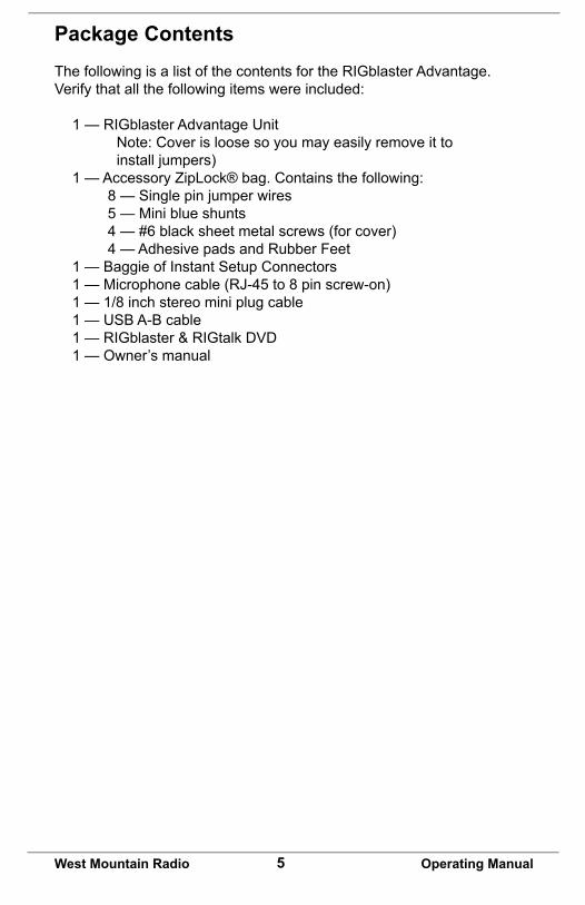
Package ContentsThe following is a list of the contents for the RIGblaster Advantage. Verify that all the following items were included:
1 — RIGblaster Advantage Unit Note: Cover is loose so you may easily remove it to install jumpers) 1 — Accessory ZipLock® bag. Contains the following: 8 — Single pin jumper wires 5 — Mini blue shunts 4 — #6 black sheet metal screws (for cover) 4 — Adhesive pads and Rubber Feet 1 — Baggie of Instant Setup Connectors 1 — Microphone cable (RJ-45 to 8 pin screw-on) 1 — 1/8 inch stereo mini plug cable 1 — USB A-B cable 1 — RIGblaster & RIGtalk DVD 1 — Owner’s manual
6West Mountain Radio Operating Manual
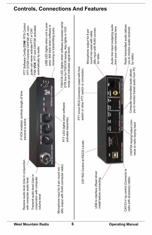
Controls, Connections And Features
Mic
roph
one
outp
ut fo
r 8 p
in
roun
d m
ic:u
sed
with
cab
le
(Mic
inpu
t with
RJ4
5 co
nnec
-to
r rad
io
PTT
in/o
ut R
CA
Con
nect
or (u
sed
with
foot
-sw
itch
or o
ther
PTT
sw
itch
or c
onne
ctio
n.
Aud
io li
ne in
put (
outg
oing
aud
io
from
you
r rad
io c
onne
cts
here
Rad
io tr
ansm
itted
aud
io (a
llow
s yo
u to
mon
itor a
udio
rece
ived
by
radi
o)C
ompu
ter t
rans
mitt
ed a
udio
allo
ws
you
to m
onito
r tra
nsit
audi
o fro
m P
CCW/FSKkeyingoutput(con-
nect
s to
radi
o ke
ying
inpu
t
CAT
RIG
Con
trol a
t RS
232
Leve
ls
CAT
/CI-V
rig
cont
rol (
Con
nect
s to
ra
dio
with
acc
esso
ry c
able
)
US
B to
inte
rface
(Rea
d dr
iver
in
stal
l bef
ore
conn
ectin
g.
PTT
SoftwareConfigC
OM
: RTS
Con
trol
PTT
DTG
RControlsCW/FSKoff:com
-pu
ter c
an n
ever
act
ivat
e P
TT o
r CW
/FS
K V
OX:PTT
andCW/FSKactivated
auto
mat
ical
ly b
y au
dio.
US
B L
ED
(lig
hts
whe
n un
it is
pow
-er
ed. W
ill b
link
whe
n so
ftwar
e is
re
ceiv
ing
or tr
ansm
ittin
g au
dio
PTT
LE
D (l
ight
s w
hen
softw
are
activ
ates
tran
smits
)
Mic
roph
one
inpu
t for
8 p
in ro
und
mic
(M
ic o
utpu
t with
RJ4
5 co
nnec
tor r
adio
)
Tran
smit
audi
o le
vel (
Use
in
conj
unct
ion
with
com
pute
r vo
lum
e le
vel
Rec
eive
aud
io le
vel (
Use
in c
onju
nctio
n w
ith c
ompu
ter a
udio
leve
l
If V
OX
ena
bled
, con
trols
leng
th o
f tim
e tra
nsm
it is
act
ive
FSK/CWLED(lightswhensoftw
areaccessesserial
DTR
lineforF
SK/CWkeying.AlsolightsinVOX
mod
e an
d in
dica
tes
sign
al le
vel)
7West Mountain Radio Operating Manual
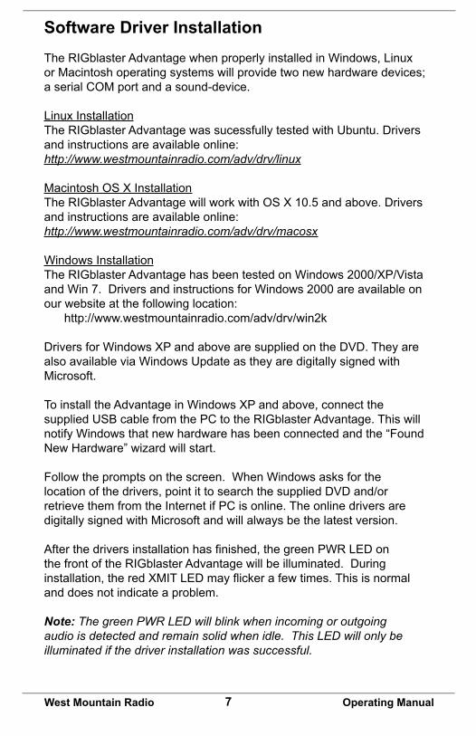
Software Driver InstallationThe RIGblaster Advantage when properly installed in Windows, Linux or Macintosh operating systems will provide two new hardware devices; a serial COM port and a sound-device.
Linux InstallationThe RIGblaster Advantage was sucessfully tested with Ubuntu. Drivers and instructions are available online:http://www.westmountainradio.com/adv/drv/linux
Macintosh OS X InstallationThe RIGblaster Advantage will work with OS X 10.5 and above. Drivers and instructions are available online:http://www.westmountainradio.com/adv/drv/macosx
Windows InstallationThe RIGblaster Advantage has been tested on Windows 2000/XP/Vista and Win 7. Drivers and instructions for Windows 2000 are available on our website at the following location: http://www.westmountainradio.com/adv/drv/win2k
Drivers for Windows XP and above are supplied on the DVD. They are also available via Windows Update as they are digitally signed with Microsoft.
To install the Advantage in Windows XP and above, connect the supplied USB cable from the PC to the RIGblaster Advantage. This will notify Windows that new hardware has been connected and the “Found New Hardware” wizard will start.
Follow the prompts on the screen. When Windows asks for the location of the drivers, point it to search the supplied DVD and/or retrieve them from the Internet if PC is online. The online drivers are digitally signed with Microsoft and will always be the latest version.
Afterthedriversinstallationhasfinished,thegreenPWRLEDonthe front of the RIGblaster Advantage will be illuminated. During installation,theredXMITLEDmayflickerafewtimes.Thisisnormaland does not indicate a problem.
Note: The green PWR LED will blink when incoming or outgoing audio is detected and remain solid when idle. This LED will only be illuminated if the driver installation was successful.
8West Mountain Radio Operating Manual
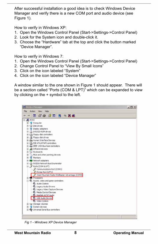
After successful installation a good idea is to check Windows Device Manager and verify there is a new COM port and audio device (see Figure 1).
How to verify in Windows XP:1. Open the Windows Control Panel (Start->Settings->Control Panel)2. Look for the System icon and double-click it.3. Choose the “Hardware” tab at the top and click the button marked “Device Manager”.
How to verify in Windows 7:1. Open the Windows Control Panel (Start->Settings->Control Panel)2. Change Control Panel to “View By Small Icons”3. Click on the icon labeled “System”4. Click on the icon labeled “Device Manager”
A window similar to the one shown in Figure 1 should appear. There will be a section called “Ports (COM & LPT)” which can be expanded to view by clicking on the + symbol to the left.
Fig 1 - Windows XP Device Manager
9West Mountain Radio Operating Manual
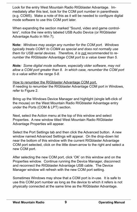
Look for the entry West Mountain Radio RIGblaster Advantage. Im-mediately after this text, look for the COM port number in parenthesis (e.g.COM5).Makeanoteofthisasitwillbeneededtoconfiguredigitalmode software to use this COM port later.
When expanding the section marked “Sound, video and game control-lers”, notice the new entry labeled USB Audio Device (or RIGblaster Advantage Audio in Win 7).
Note: Windows may assign any number for the COM port. Windows typically treats COM1 to COM4 as special and does not normally use them for USB serial devices. Therefore, it is not recommended to re-number the RIGblaster Advantage COM port to a value lower than 5.
Note: Some digital mode software, especially older software, may not allow a COM port greater than 8. In which case, renumber the COM port to a value within the range 5-8.
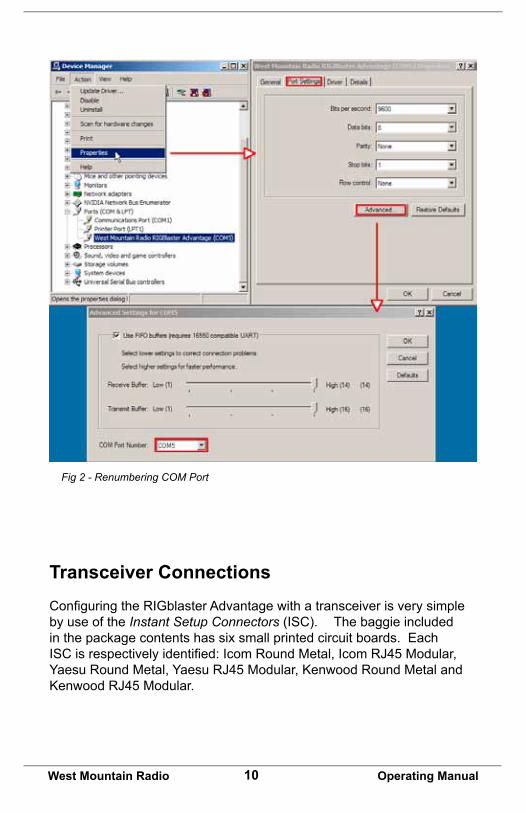
How to renumber the RIGblaster Advantage COM port.If needing to renumber the RIGblaster Advantage COM port in Windows, refer to Figure 2.
Bring up the Windows Device Manager and highlight (single left-click of the mouse) on the West Mountain Radio RIGblaster Advantage entry under the Ports (COM & LPT) section.
Next, select the Action menu at the top of this window and select Properties. A new window titled West Mountain Radio RIGblaster Advantage Properties will appear.
Select the Port Settings tab and then click the Advanced button. A new window named Advanced Settings will appear. On the drop-down list near the bottom of this window with the current RIGblaster Advantage COM port selected, click on the little down-arrow to the right and select a new COM port.
AfterselectingthenewCOMport,click‘OK’onthiswindowandontheProperties window. Continue running the Device Manager, disconnect and reconnect the RIGblaster Advantage USB cable. The Device Manager window will refresh with the new COM port setting.
Sometimes Windows may show that a COM port is in-use. It is safe to use this COM port number as long as the device to which it refers is not physically connected at the same time as the RIGblaster Advantage.
10West Mountain Radio Operating Manual
Fig 2 - Renumbering COM Port
Transceiver ConnectionsConfiguringtheRIGblasterAdvantagewithatransceiverisverysimpleby use of the Instant Setup Connectors (ISC). The baggie included in the package contents has six small printed circuit boards. Each ISCisrespectivelyidentified:IcomRoundMetal,IcomRJ45Modular,YaesuRoundMetal,YaesuRJ45Modular,KenwoodRoundMetalandKenwoodRJ45Modular.
11West Mountain Radio Operating Manual
Depending on the transceiver in use, one of these ISCs will need to be installed inside the RIGblaster Advantage before use. They take care of all the microphone connection wiring that previously was done by installing jumper wires and shunts. If using a non-standard microphone wiring, jumper wires and and blue shunts have been provided in the package contents. The ISCs cover most popular brands and models of radios.
Choosing the Correct ISC
Observe the microphone connector on the radio. Typically it will be one of two types – either an 8-pin round metal connector or an RJ-45 “square” modular jack. The RIGblaster Advantage is designed to interface the transceiver through the microphone jack. Be sure to select the ISC that matches the connector on the radio. If unsure which ISC to use,refer to the back of this manual and for a chart of common radios and the correct ISC to use.
Example:TheIcom706MKIIGusesanIcom RJ45 Modular jack. A Yaesu FT-897D uses a Yaesu RJ45 Modularjack.AKenwood TS-590S uses a Kenwood 8 Pin Round Metal jack.
Note: Some radios use a 4-pin round microphone connector, these include some Kenwood and Ten-Tec radios. An adapter will be needed to use the RIGblaster Advantage with these radios. The correct adapter is sku #58136-1000 and available online for purchase.
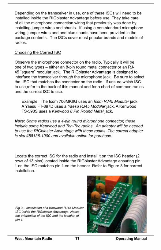
Fig 3 – Installation of a Kenwood RJ45 Modular ISC inside the RIGblaster Advantage. Notice the orientation of the ISC and the location of pin 1.
Locate the correct ISC for the radio and install it on the ISC header (2 rows of 13 pins) located inside the RIGblaster Advantage ensuring pin 1 on the ISC matches pin 1 on the header. Refer to Figure 3 for correct installation.
12West Mountain Radio Operating Manual
Now hook up the RIGblaster Advantage to the radio. Follow the steps in the next section and refer to the connection diagram at the back of this manual.
Required Connections
1. Disconnect the microphone from the transceiver.
2. Reconnect the microphone to the RIGblaster Advantage. Note: There will be only one connector on the Advantage that will mate with the microphone plug; either the 8-pin round metal socket mating to the front panel or the square RJ-45 connector mating to the rear panel.
3. Connect the 8-pin (round) to RJ-45 (square) microphone cable, included in the package contents, to the transceiver’s microphone input socket. There will be only one end that will mate with the transceiver’s microphone socket.
4. Connect the other end of the microphone cable to the RIGblaster Advantage.
5. Take the 1/8” inch stereo patch cable and connect one end to the transceiver’s speaker out (or headphone) jack. Note: If the transceiver uses a 1/4” jack, it will require use of 1/8” inch to 1/4” stereo adapter.
6. The other end of the patch cable should be connected to the jack labeled LINE IN on the rear of the RIGblaster Advantage.
Optional Connections
Additional jacks are provided on the rear of the RIGblaster Advantage for operation enhancement:
1. Serial DB-9. This connector can be used to interface some transceivers that require RS-232C level CAT. Note: This serial connector is a hardware extension of the USB virtual serial port. All lines are connected but take note that some control lines are used by the RIGblaster Advantage for PTT & CW/FSK. See page 14 for details.
13West Mountain Radio Operating Manual
2. CTL IN/OUT. This is a TTL level jack providing CI-V/CAT rig control. Many radios can be interfaced to this jack with a low-cost cable for complete rig control with suitable software (e.g. Ham Radio Deluxe, OmniRig, DX Labs Commander etc.)
3. CW/FSK.ThisjackcanbeusedforserialportCWkeyingorFSK shift if your transceiver supports it. See page 14 for details.
4. AUDIO OUT. This jack provides a transmitted audio output. Connect an external speaker here for transmit monitoring.
5. SPKR OUT. This jack provides a rig receive audio output. Connect an external speaker here to hear receive audio.
6. PTT IN/OUT. This RCA phono jack is primarily used for connection to a foot-switch for PTT. The contacts are in parallel with the Advantage PTT relay (rated 30 VDC 2A max.) and in parallelwiththetransceiver’smicrophonePTTline,andwillfloat at the same voltage.
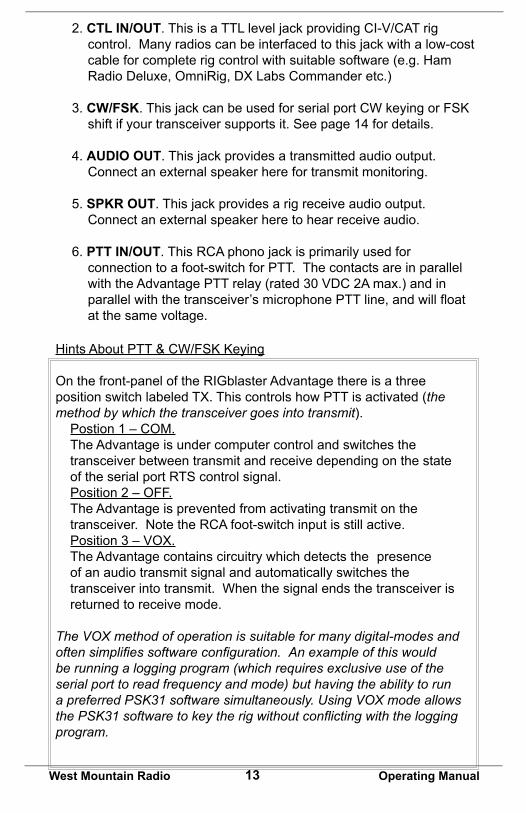
HintsAboutPTT&CW/FSKKeying
On the front-panel of the RIGblaster Advantage there is a three position switch labeled TX. This controls how PTT is activated (the method by which the transceiver goes into transmit).
Postion 1 – COM.The Advantage is under computer control and switches the transceiver between transmit and receive depending on the state of the serial port RTS control signal.Position 2 – OFF.The Advantage is prevented from activating transmit on the transceiver. Note the RCA foot-switch input is still active.Position 3 – VOX.The Advantage contains circuitry which detects the presence of an audio transmit signal and automatically switches the transceiver into transmit. When the signal ends the transceiver is returned to receive mode.
The VOX method of operation is suitable for many digital-modes and often simplifies software configuration. An example of this would be running a logging program (which requires exclusive use of the serial port to read frequency and mode) but having the ability to run a preferred PSK31 software simultaneously. Using VOX mode allows the PSK31 software to key the rig without conflicting with the logging program.
14West Mountain Radio Operating Manual
Note that this method of VOX operation applies only to the RIGblaster Advantage – there is no need to use the transceiver VOX setting.
Morse (CW) Operation
The RIGblaster Advantage has two methods of sending Morse Code (CW). One method is using MCW (Modulated or Tone CW) in SSB or FM modes. Some computer software will only produce this type of CW.
The second, and preferred, method is to use serial port keying. Connect a stereo patch cable from the RIGblaster Advantage’s CW/FSKjacktothetransceiver’sCWkeyingjack.ThiswillpermitMorseoperation when using the radio’s CW mode with suitable software.
This hardware CW keying can be realized by use of the DTR control lineontheUSBvirtualCOMport.Inpractice,needingtoconfigurethe CW software to use RTS for PTT and DTR for keying. Refer to page 28 of this manual for an example of setting up CW keying using the MRP40 software.
It is also possible to operate MCW in VOX mode, in which case the DTR circuit is logically OR’ed with PTT - the result is hardware keying from software which only uses the MCW method. Further, by disconnecting the microphone cable, but leave the CW keying cable connected,allowingtooperateQSK(break-inCW)frommostCWsoftware.
By using a dual 1/8th inch stereo adaptor plug (or ‘Y’ splitter cable), connecttheMorseKeyinparallelwiththeCWjack.Theoutputisopencollectorsoissafetousewithcontact-closureMorseKeysand modern “pull to ground” electronic keyers. This will allow to send computerMorseorusethekeyformaximumflexibility.Warning: Do not attempt this if your radio uses grid-block keying or cathode keying - you will destroy your Advantage!
RTTY Operation
Similar to CW, there are two methods used to generate RTTY signals.MethodoneisAFSKRTTYbeingusedinSSBmode.Thisrelies on the software to generate the RTTY tones. Most digital-mode software will use this method.
15West Mountain Radio Operating Manual
Setting Audio LevelsProper audio level setting is crucial to successful digital-mode transmission. The RIGblaster Advantage transmit audio level can be set by use of the Windows volume slider and the front-panel XMIT LEVEL control. Receive level can be set by the Windows recording volume slider and the front-panel RCV LEVEL control.
It is recommended to set the RIGblaster Advantage audio device levels to 50% for both “recording” and “playback” within Windows. Fine tuning can then be made using the XMIT & RCV level controls on the front of the Advantage.
Note: It is important not to set the RIGblaster Advantage as the default Windows audio device. This will prevent any unintentional transmissions if operating in VOX mode (Windows audio-alerts, music etc).
Note: Some older digital-mode software only uses the default sound-card in Windows for output. If using older software be careful when changing the default Windows sound-card to the Advantage. In this case, it is recommended to change the Windows sound scheme to silent.
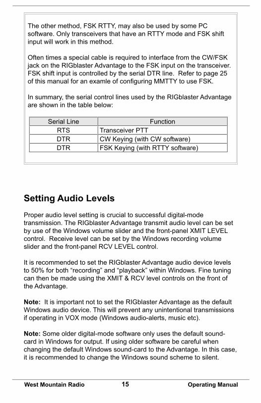
Serial Line FunctionRTS Transceiver PTTDTR CWKeying(withCWsoftware)DTR FSKKeying(withRTTYsoftware)
Theothermethod,FSKRTTY,mayalsobeusedbysomePCsoftware.OnlytransceiversthathaveanRTTYmodeandFSKshiftinput will work in this method.
OftentimesaspecialcableisrequiredtointerfacefromtheCW/FSKjackontheRIGblasterAdvantagetotheFSKinputonthetransceiver.FSKshiftinputiscontrolledbytheserialDTRline.Refertopage25ofthismanualforanexamleofconfiguringMMTTYtouseFSK.
In summary, the serial control lines used by the RIGblaster Advantage are shown in the table below:
16West Mountain Radio Operating Manual
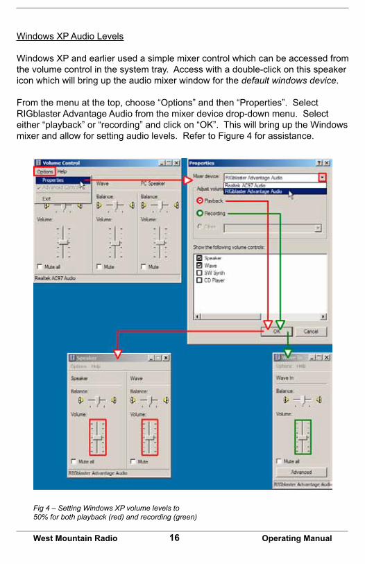
Fig 4 – Setting Windows XP volume levels to50% for both playback (red) and recording (green)
Windows XP Audio Levels
Windows XP and earlier used a simple mixer control which can be accessed from the volume control in the system tray. Access with a double-click on this speaker icon which will bring up the audio mixer window for the default windows device.
From the menu at the top, choose “Options” and then “Properties”. Select RIGblaster Advantage Audio from the mixer device drop-down menu. Select either“playback”or“recording”andclickon“OK”.ThiswillbringuptheWindowsmixer and allow for setting audio levels. Refer to Figure 4 for assistance.
17West Mountain Radio Operating Manual
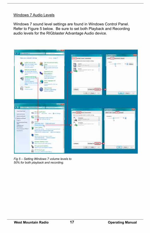
Windows 7 Audio Levels
Windows 7 sound level settings are found in Windows Control Panel. Refer to Figure 5 below. Be sure to set both Playback and Recording audio levels for the RIGblaster Advantage Audio device.
Fig 5 – Setting Windows 7 volume levels to50% for both playback and recording.
18West Mountain Radio Operating Manual
Digital-Mode OperatingThis section provides a quick overview of some of the most popular and current ham radio software that has been tested with the Advantage. KeepinginmindthattheseareThird-Partysoftwareprograms,WestMountain Radio cannot guarantee it will work with every particular PC & radio. Most of this software is under constant development so some features referred to in this manual may not be exactly as described in future versions released by the respective authors. Also included are screencapturestoaidinconfiguringthesoftwarewiththeRIGblasterAdvantage.
Multi-Mode Software: FLDigi
Modescovered:CW,Contestia,DominoEX,Hell,MFSK,MT63,Olivia,PSK,QPSK,PSKR,RTTY,THOR,Throb,WEFAX,NBEMSmodes.
W1HKJ’sFLdigiisaverycapable,cost-free,andeasytousedigital-mode program. It has all of the most popular modes in use today (includingPSK31)anditsdecodeperformanceishighlyregarded.Itis used by HF operators, ragchewers, contesters, experimenters and EMCOMM users alike. Many of its EMCOMM modes (NBEMS) are used on HF & VHF under control of other software which provides error-checkingandautomaticrepeatrequest(ARQ).Italsosupportslogging-integrated rig-control (CAT/CI-V) by a variety of methods.
Note: The CW mode in FLdigi is tone modulated Morse Code (MCW). Normally operated in SSB mode on HF and FM mode on VHF/UHF.
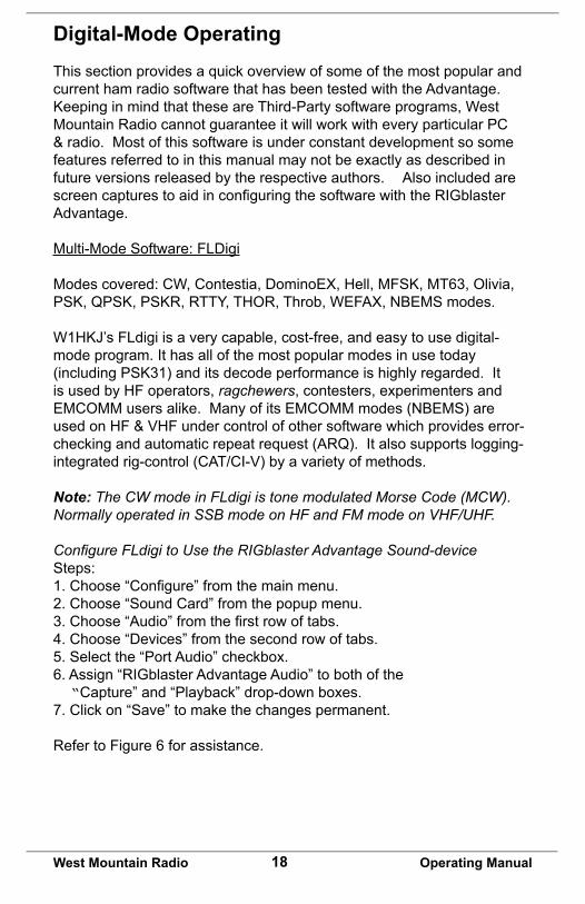
Configure FLdigi to Use the RIGblaster Advantage Sound-deviceSteps:1.Choose“Configure”fromthemainmenu.2. Choose “Sound Card” from the popup menu.3.Choose“Audio”fromthefirstrowoftabs.4. Choose “Devices” from the second row of tabs.5. Select the “Port Audio” checkbox.6. Assign “RIGblaster Advantage Audio” to both of the “Capture” and “Playback” drop-down boxes.7. Click on “Save” to make the changes permanent.
Refer to Figure 6 for assistance.
19West Mountain Radio Operating Manual
Fig 6 – Configuring FLdigi to use the RIGblaster Advantage sound-device.
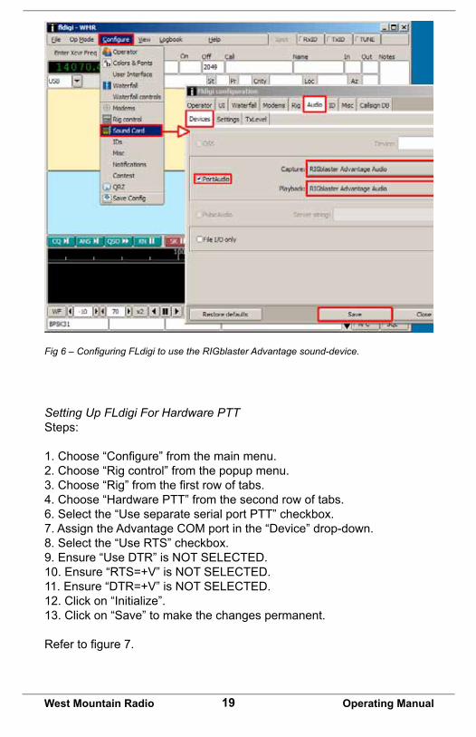
Setting Up FLdigi For Hardware PTTSteps:
1.Choose“Configure”fromthemainmenu.2. Choose “Rig control” from the popup menu.3.Choose“Rig”fromthefirstrowoftabs.4. Choose “Hardware PTT” from the second row of tabs.6. Select the “Use separate serial port PTT” checkbox.7. Assign the Advantage COM port in the “Device” drop-down.8. Select the “Use RTS” checkbox.9. Ensure “Use DTR” is NOT SELECTED.10. Ensure “RTS=+V” is NOT SELECTED.11. Ensure “DTR=+V” is NOT SELECTED.12. Click on “Initialize”.13. Click on “Save” to make the changes permanent.
Refertofigure7.
20West Mountain Radio Operating Manual
Fig 7 – Configuring PTT in FLdigi.
Setting Up FLdigi For Rig-controlFLdigi offers a number of methods of rig-control; beyond the scope of this manual to detail them all. Hamlib (on the rig-control tab) may be the simplestmethod,asFLdigicomeswithrigdescriptionfilesforthislibrary.
RigCATisanothergoodmethod.Downloadarigdescriptionfileforaspecificradiobygoingto:http://www.w1hkj.com/xmlarchives.html.
TypicalConfiguration:
1. Specify the Advantage COM port as the rig-control “device”. Note: Do not set RTS or DTR high, otherwise, the transceiver may go into transmit when the program first loads!
2. Match the transceiver’s communication settings – check CAT baud rate and CI-V address (Icom).
3. Flow control is not usually needed, but if needed, use XON/XOFF as the method. Never choose hardware CTS/RTS.
21West Mountain Radio Operating Manual
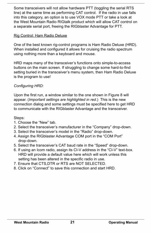
Some transceivers will not allow hardware PTT (toggling the serial RTS line) at the same time as performing CAT control. If the radio in use falls into this category, an option is to use VOX mode PTT or take a look at the West Mountain Radio RIGtalk product which will allow CAT control on a separate serial port, freeing the RIGblaster Advantage for PTT.
Rig Control: Ham Radio Deluxe
One of the best known rig-control programs is Ham Radio Deluxe (HRD). Wheninstalledandconfigureditallowsforcruisingtheradiospectrumusing nothing more than a keyboard and mouse.
HRD maps many of the transceiver’s functions onto simple-to-access buttonsonthemainscreen.Ifstrugglingtochangesomehard-to-findsetting buried in the transceiver’s menu system, then Ham Radio Deluxe is the program to use!
Configuring HRD:
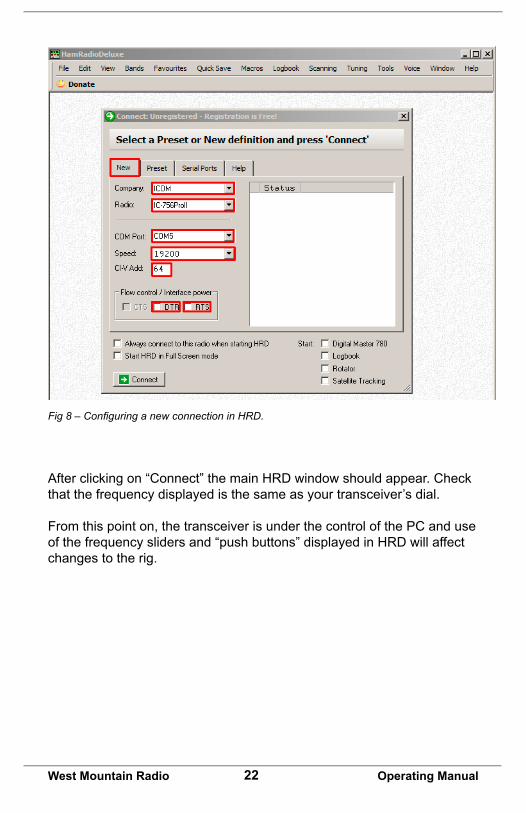
Uponthefirstrun,awindowsimilartotheoneshowninFigure8willappear. (Important settings are highlighted in red.) This is the new connectiondialogandsomesettingsmustbespecifiedheretogetHRDto communicate with the RIGblaster Advantage and the transceiver.
Steps:1. Choose the “New” tab.2. Select the transceiver’s manufacturer in the “Company” drop-down.3. Select the transceiver’s model in the “Radio” drop-down.4. Assign the RIGblaster Advantage COM port in the “COM Port” drop-down.5. Select the transceiver’s CAT baud rate in the “Speed” drop-down.6. If using an Icom radio, assign its CI-V address in the “CI-V” text-box. HRD will provide a default value here which will work unless this settinghasbeenalteredinthespecificradioinuse.7. Ensure that CTS,DTR or RTS are NOT SELECTED.8. Click on “Connect” to save this connection and start HRD.
22West Mountain Radio Operating Manual
After clicking on “Connect” the main HRD window should appear. Check that the frequency displayed is the same as your transceiver’s dial.
From this point on, the transceiver is under the control of the PC and use of the frequency sliders and “push buttons” displayed in HRD will affect changes to the rig.
Fig 8 – Configuring a new connection in HRD.
23West Mountain Radio Operating Manual
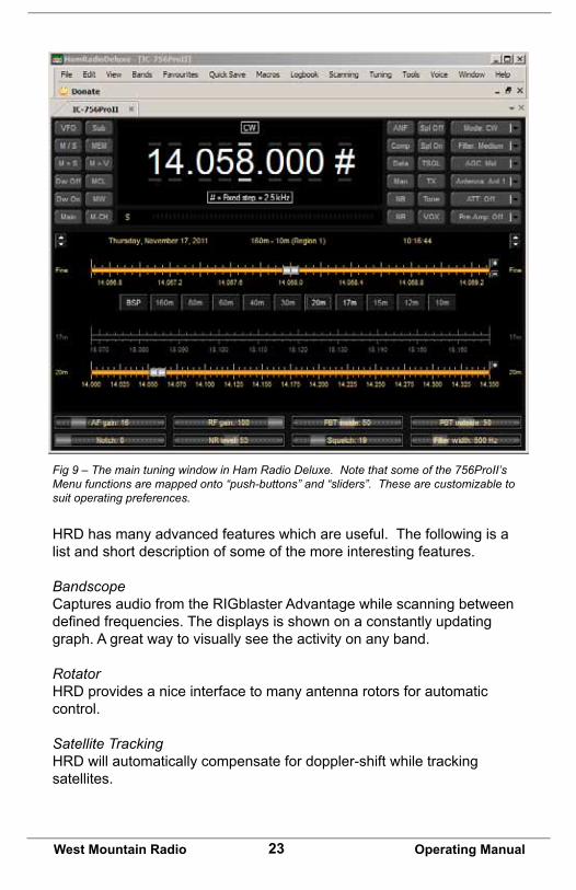
Fig 9 – The main tuning window in Ham Radio Deluxe. Note that some of the 756ProII’s Menu functions are mapped onto “push-buttons” and “sliders”. These are customizable to suit operating preferences.
HRD has many advanced features which are useful. The following is a list and short description of some of the more interesting features.
BandscopeCaptures audio from the RIGblaster Advantage while scanning between definedfrequencies.Thedisplaysisshownonaconstantlyupdatinggraph. A great way to visually see the activity on any band.
RotatorHRD provides a nice interface to many antenna rotors for automatic control.
Satellite TrackingHRD will automatically compensate for doppler-shift while tracking satellites.
24West Mountain Radio Operating Manual
DM780Digital Master 780 is a very feature-rich digital-Mode program. Operate PSK31andmanyothermodeswhileintegratingloggingwithHamRadioDeluxe. Consider trying the “Super Browser” which will decode multiple PSK31transmissionssimultaneously.
IP ServerProvides a TCP/IP interface for remote station control. Use HRD to control your radio from anywhere with an internet connection.
RTTY:ConfiguringMMTTYForFSKMMTTY by Makoto Mori (JE3HHT) is used worldwide for RTTY and for good reason – its decode performance is excellent, makes tuning RTTY signals very simple, and integrates into popular contest logging software. The latest version of MMTTY can be downloaded from Mako’s website at: http://hamsoft.ca
One of the features that make MMTTY (almost) unique is that it supports FSKRTTYwhichisoftenthepreferredwaytogenerateRTTYtonesifthe transceiver supports it.
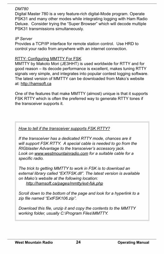
How to tell if the transceiver supports FSK RTTY?
If the transceiver has a dedicated RTTY mode, chances are it will support FSK RTTY. A special cable is needed to go from the RIGblaster Advantage to the transceiver’s accessory jack. Look on www.westmountainradio.com for a suitable cable for a specific radio.
The trick to getting MMTTY to work in FSK is to download an external library called “EXTFSK.dll”. The latest version is available on Mako’s website at the following location: http://hamsoft.ca/pages/mmtty/ext-fsk.php
Scroll down to the bottom of the page and look for a hyperlink to a zip file named “ExtFSK106.zip”.
Download this file, unzip it and copy the contents to the MMTTY working folder, usually C:\Program Files\MMTTY.
25West Mountain Radio Operating Manual
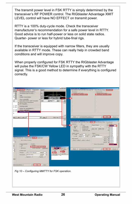
Then follow the steps below and refer to figure 10 to configure MMTTY with the RIGblaster Advantage.
1. Select the “Option” menu from MMTTY.2. Choose “Setup MMTTY”.3. From the setup window choose “SoundCard” from the tabs at the top of the window.4. Select RIGblaster Advantage Audio for both “Reception” and “Transmission”. Although we are not actually using the Advantage sound-card for RTTY transmission (using FSK) setting it this way will allow for monitoring the signals on the AUDIO OUT jack in addition to keying the FSK line of the transceiver.5. Choose the “MISC” tab from the tabs at the top of the window.6. Select “Sound + COM-TxD (FSK)” in the “TX Port” frame.7. Choose the “TX” tab from the tabs at the top of the window.8. Select EXTFSK from the “Port” drop-down.9. A new window will appear titled “EXTFSK 1.06”. On this window, assign the RIGblaster Advantage COM port and choose DTR for “FSK output” and RTS for “PTT output”. Notice the “Status: OK” message near the top. If it is showing red and “NG” then MMTTY is reporting it was unable to open the COM port. Make sure no other software is running which has already claimed the COM port (e.g. HRD).10. Verify that the optional RTTY FSK cable is connected to the transceiver from the Advantage CW/FSK jack.11. Put the transceiver into its RTTY mode.
HintsAboutOperatingFSKRTTY
ChecktheFSKsettingsontheradio–for45baudRTTY,theshift shoud be set to 170Hz. Many radios also offer a choice of MARKtones(e.g.2125Hz,1275Hz).Therewillbenodifferenceinoperating when choosing either setting.
FSKpolarityvariesfromrigtorig,soattempttotuneinsomeRTTYto check that it is not “Upside Down”. A friendly station can help check your transmissions for correct polarity.
(cont’d)
26West Mountain Radio Operating Manual
ThetransmitpowerlevelinFSKRTTYissimplydeterminedbythetransceiver’s RF POWER control. The RIGblaster Advantage XMIT LEVEL control will have NO EFFECT on transmit power.
RTTY is a 100% duty-cycle mode. Check the transceiver manufacturer’s recommendation for a safe power level in RTTY. Good advice is to run half-power or less on solid state radios. Quarter-powerorlessforhybridtube-finalrigs.
Ifthetransceiverisequippedwithnarrowfilters,theyareusuallyavailable in RTTY mode. These can really help in crowded band conditions and will improve copy.
WhenproperlyconfiguredforFSKRTTYtheRIGblasterAdvantagewillpulsetheFSK/CWYellowLEDinsympathywiththeRTTYsignal.Thisisagoodmethodtodetermineifeverythingisconfiguredcorrectly.
Fig 10 – Configuring MMTTY for FSK operation.
27West Mountain Radio Operating Manual
CW:ConfiguringMRP40ForCWOperation
Although there are free CW (Morse Code) decoding programs the performance of many leave a lot to be desired. MRP40 by Norbert Pieper is an excellent CW decoder, even under weak signal conditions &QSB.ItsupportstransmissionofMorseCodefromthePCkeyboardusingtheCW/FSKjackontheRIGblasterAdvantage.
A 30 day trial version of the software is available to download from: http://www.polar-electric.com/
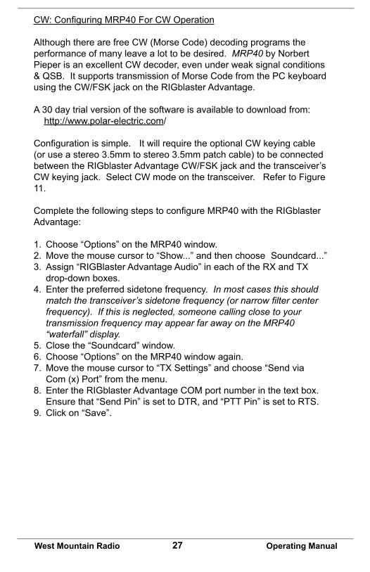
Configurationissimple. It will require the optional CW keying cable (or use a stereo 3.5mm to stereo 3.5mm patch cable) to be connected betweentheRIGblasterAdvantageCW/FSKjackandthetransceiver’sCW keying jack. Select CW mode on the transceiver. Refer to Figure 11.
CompletethefollowingstepstoconfigureMRP40withtheRIGblasterAdvantage:
1. Choose “Options” on the MRP40 window.2. Move the mouse cursor to “Show...” and then choose Soundcard...”3. Assign “RIGBlaster Advantage Audio” in each of the RX and TX drop-down boxes.4. Enter the preferred sidetone frequency. In most cases this should match the transceiver’s sidetone frequency (or narrow filter center frequency). If this is neglected, someone calling close to your transmission frequency may appear far away on the MRP40 “waterfall” display.5. Close the “Soundcard” window.6. Choose “Options” on the MRP40 window again.7. Move the mouse cursor to “TX Settings” and choose “Send via Com (x) Port” from the menu.8. Enter the RIGblaster Advantage COM port number in the text box. Ensure that “Send Pin” is set to DTR, and “PTT Pin” is set to RTS.9. Click on “Save”.
28West Mountain Radio Operating Manual
Other Ideas For CW (Morse Code)• If you want to try a freeware CW decoder then take a look at
FLdigi as it’s CW performance, while not as good as MRP40, is certainly good enough to copy the stronger stations that send well-formed Morse Code.
• CWType is a freeware CW keyboard terminal (no decoding) but thissoftwarewillletyoutransmitMorseCodeusingtheCW/FSKjack. See http://www.dxsoft.com/en/products/cwtype/
• MultiPSKalsohasagoodCWdecoderandisfreeforthispurpose. Check out http://f6cte.free.fr/
• Learn Morse Code, purchase our TOUCHkeyer and have some hands-on CW fun!
Fig 11 – Setting up MRP40 to use hardware keying with the RIGblaster Advantage.
29West Mountain Radio Operating Manual
JT65:ConfiguringJT65-HF.
The“JT”seriesofmodeswereoriginallydevelopedbyJoeTaylor,K1JTto be very weak signal VHF modes suitable for EME, Troposcatter & Meteor trail methods of ionospheric propagation. Since that time, one mode JT65(A) has become very popular on HF for long-distance low-powercontacts.ContactsmaybeabettertermthanQSOasthetransmission rate is very slow with each “over” taking a little less than 1 minute in each direction.
Signal-to-noise ratios are often well below hearing threshold and it is not uncommon to perfectly decode a transmission at levels around -25dB S/N. Originally JT65 operation was only possible using WSJT software producedbyK1JTandshortlyaftertheMultiPSKprogram(F6CTE).While both of these programs are technically excellent they are not necessarily the easiest to use.
JT65-HFisarecentadditiondevelopedbyJoeLarge,W6CQZ.Forstraightforward HF operation in JT65 this is the easiest software to configureandsimplesttouse.
FollowthestepsbelowtoconfigureJT65-HF.RefertoFigure12forassistance.
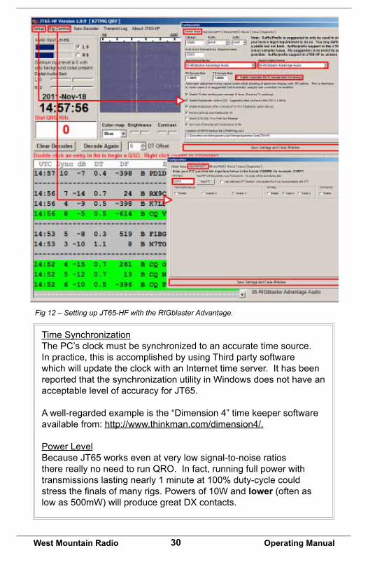
1. Click on “Setup” on the JT65-HF main window.2. Selectthe“StationSetup”tabatthetopoftheconfigurationwindow.3. Assign the RIGblaster Advantage Audio to the sound-card input & output device drop-down boxes.4. Ensure “Enable Automatic RX/TX Sample Rate Correction” is checked.5. Be sure to enter your callsign and Maidenhead grid locator.6. Selectthe“RigControl/PTT”tabatthetopoftheconfiguration window.7. Type the RIGblaster Advantage COM port into the “PTT port”.8. Click on “Save Settings and Close Window”.
Hints for JT65-HF
Receive Audio LevelIt is very important to set the receive level correctly for optimum JT65 decoding. Notice the “Adjust Input Levels” box in Figure 12. The sliders are adjustable, but it is easier to adjust the RIGblaster Advantage RCV LEVEL control until L0 and R0 (on a quiet frequency) are achieved.
30West Mountain Radio Operating Manual
Fig 12 – Setting up JT65-HF with the RIGblaster Advantage.
Time SynchronizationThe PC’s clock must be synchronized to an accurate time source. In practice, this is accomplished by using Third party software which will update the clock with an Internet time server. It has been reported that the synchronization utility in Windows does not have an acceptable level of accuracy for JT65.
A well-regarded example is the “Dimension 4” time keeper software available from: http://www.thinkman.com/dimension4/.
Power LevelBecause JT65 works even at very low signal-to-noise ratios therereallynoneedtorunQRO.Infact,runningfullpowerwithtransmissions lasting nearly 1 minute at 100% duty-cycle could stressthefinalsofmanyrigs.Powersof10Wandlower (often as low as 500mW) will produce great DX contacts.
31West Mountain Radio Operating Manual
WinMOR: Using RMS Express & Winlink 2000
Until recently there wre few choices of sound-card software which could interface to the Winlink 2000 radio e-mail system. Most users bought expensive Pactor modems for HF and TNC’s for VHF.
On VHF it was possible to use sound-card packet, but it was not easy to integrate with a mail client. On HF, the choices were even more limited and still did not integrate with a simple mail client.
RickMuething,KN6KBrecentlydevelopedtheWinMORsound-cardmodem which made the Winlink 2000 system available for anyone with an HF transceiver. The WinMOR software modem was integrated into a full mail client by the Winlink development team. This product is called RMS Express and is freely down-loadable from the Winlink 2000 website: http://www.winlink.org/ClientSoftware
Using RMS Express requires an understanding of the Winlink 2000 system. This manual only covers getting it working with the RIGblaster Advantage.
To learn more, we recommend starting at the Winlink 2000 website: http://www.winlink.org/, especially http://www.winlink.org/GetStarted.
ConfiguringRMSExpress
RefertoFigure13andcompletethestepsthatfollowtoconfigureRMSExpress with the RIGblaster Advantage.
Steps:1. SelectWinmorWL2Kfromthedrop-downboxontheRMS Express main window.2. Click on “Open Session” (to the left of the dropdown).3. The “Winmor Winlink 2000 Session” window will appear.4. Choose “Setup” from the menu at the top of this window.
32West Mountain Radio Operating Manual
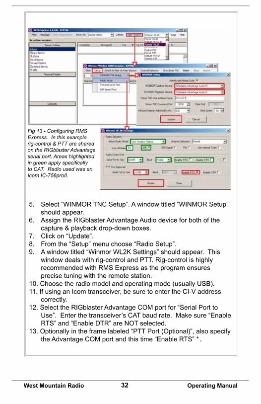
5. Select “WINMOR TNC Setup”. A window titled “WINMOR Setup” should appear.6. Assign the RIGblaster Advantage Audio device for both of the capture & playback drop-down boxes.7. Click on “Update”.8. From the “Setup” menu choose “Radio Setup”.9. Awindowtitled“WinmorWL2KSettings”shouldappear.This window deals with rig-control and PTT. Rig-control is highly recommended with RMS Express as the program ensures precise tuning with the remote station.10. Choose the radio model and operating mode (usually USB).11. If using an Icom transceiver, be sure to enter the CI-V address correctly.12. Select the RIGblaster Advantage COM port for “Serial Port to Use”. Enter the transceiver’s CAT baud rate. Make sure “Enable RTS” and “Enable DTR” are NOT selected. 13. Optionally in the frame labeled “PTT Port (Optional)”, also specify the Advantage COM port and this time “Enable RTS” *.
Fig 13 - Configuring RMSExpress. In this example rig-control & PTT are shared on the RIGblaster Advantage serial port. Areas highlighted in green apply specifically to CAT. Radio used was an Icom IC-756proII.
33West Mountain Radio Operating Manual
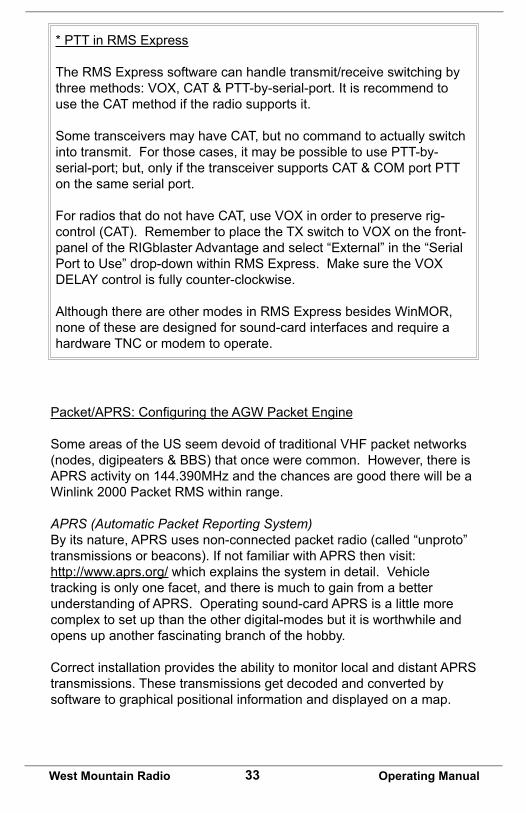
* PTT in RMS Express
The RMS Express software can handle transmit/receive switching by three methods: VOX, CAT & PTT-by-serial-port. It is recommend to use the CAT method if the radio supports it.
Some transceivers may have CAT, but no command to actually switch into transmit. For those cases, it may be possible to use PTT-by-serial-port; but, only if the transceiver supports CAT & COM port PTT on the same serial port.
For radios that do not have CAT, use VOX in order to preserve rig-control (CAT). Remember to place the TX switch to VOX on the front-panel of the RIGblaster Advantage and select “External” in the “Serial Port to Use” drop-down within RMS Express. Make sure the VOX DELAY control is fully counter-clockwise.
Although there are other modes in RMS Express besides WinMOR, none of these are designed for sound-card interfaces and require a hardware TNC or modem to operate.
Packet/APRS:ConfiguringtheAGWPacketEngine
Some areas of the US seem devoid of traditional VHF packet networks (nodes, digipeaters & BBS) that once were common. However, there is APRS activity on 144.390MHz and the chances are good there will be a Winlink 2000 Packet RMS within range.
APRS (Automatic Packet Reporting System)By its nature, APRS uses non-connected packet radio (called “unproto” transmissions or beacons). If not familiar with APRS then visit:http://www.aprs.org/ which explains the system in detail. Vehicle tracking is only one facet, and there is much to gain from a better understanding of APRS. Operating sound-card APRS is a little more complex to set up than the other digital-modes but it is worthwhile and opens up another fascinating branch of the hobby.
Correct installation provides the ability to monitor local and distant APRS transmissions. These transmissions get decoded and converted by software to graphical positional information and displayed on a map.
34West Mountain Radio Operating Manual
Other information that is encapsulated in the transmission can include weather observations, real-time hazards, telemetry, messaging and local information for travelers. Look for a possible APRS transmissions that have been “digipeated” via the International Space Station (ISS).
Get Started with Packet Radio ExampleThis example will use the AGWPE software written by George Rossopoulos (SV2AGW).
Packet radio is a layered technology. One layer is the actual hardware, (in this case the radio and the RIGblaster Advantage), on top of that layer is a packet driver (the AGW program) and on top of that layer would be the APRS program itself.
1. Install the AGWPE software. The latest version may be down- loaded from: http://www.sv2agw.com/downloads/default.htm2. LookforthefilecalledAGWPE.zip.Thisisthefreewareversion. SV2AGW also has a “pro” version which has expanded features and may work better with Windows 7. The upgrade may be worth- while if planning to use Packet Radio often.3. Unzipthefiletoafolder(suggestedC:\AGW).Thereisnoinstall program, so execute by double-clicking on the “AGW Packet Engine.exe”file.4. A“splash”screenwillfirstappearexplainingAGWPEandanew icon will appear in the Windows system tray.5. Refer to Figures 14 & 15 while performing the following steps:
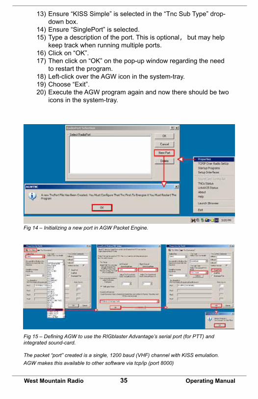
1) Left-click over the AGW icon in the system tray.2) Choose “Properties” from the pop-up menu.3) Click on “New Port” from the RadioPort Selection window.4) Clickon“OK”onthepop-updialogwindowinformingofthe new TNC port that has been created.5) A new window titled “Properties For Port1” should appear.6) Select the RIGblaster Advantage COM port in the “Select Port” drop-down box.8) Ignore the “SerialPort/Modem Baudrate” drop-down.9) Choose “SoundCard” from the “TNC Type” drop-down box. Then another window titled “SoundCard Modem/TNC Setup” will appear.10) Ensure that both left & right channels are set to 1200 baud.11) Assign “RIGblaster Advantage Audio” in the sound-card drop-down box.12) Clickon“OK”togobacktothepreviouswindow.
35West Mountain Radio Operating Manual
13)Ensure“KISSSimple”isselectedinthe“TncSubType”drop- down box.14) Ensure “SinglePort” is selected.15) Type a description of the port. This is optional, but may help keep track when running multiple ports.16)Clickon“OK”.17)Thenclickon“OK”onthepop-upwindowregardingtheneed to restart the program.18) Left-click over the AGW icon in the system-tray.19) Choose “Exit”.20) Execute the AGW program again and now there should be two icons in the system-tray.
Fig 15 – Defining AGW to use the RIGblaster Advantage’s serial port (for PTT) and integrated sound-card. The packet “port” created is a single, 1200 baud (VHF) channel with KISS emulation. AGW makes this available to other software via tcp/ip (port 8000)
Fig 14 – Initializing a new port in AGW Packet Engine.
36West Mountain Radio Operating Manual
Thattakescareofthefirstandsecond“layer”ofpacket-radio.Thisdefinedapacketport(withKISSemulation)whichcannowbeusedbyother software.
The AGWTracker software will now be used for an APRS example, again written by George Rossopoulos (SV2AGW).
Check for the latest version to install: http://www.sv2agw.com/downloads/default.htm
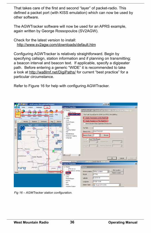
ConfiguringAGWTrackerisrelativelystraightforward.Beginbyspecifying callsign, station information and if planning on transmitting; a beacon interval and beacon text. If applicable, specify a digipeater path. Before entering a generic “WIDE” it is recommended to take a look at http://wa8lmf.net/DigiPaths/ for current “best practice” for a particular circumstance.
RefertoFigure16forhelpwithconfiguringAGWTracker.
Fig 16 – AGWTracker station configuration.
37West Mountain Radio Operating Manual
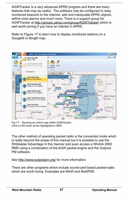
AGWTracker is a very advanced APRS program and there are many featuresthatmaybeuseful.Thesoftwaremaybeconfiguredtorelaymonitored beacons to the Internet, add and manipulate APRS objects, definezonealarmsandmuchmore.ThereisasupportgroupforAGWTracker at http://groups.yahoo.com/group/AGWTracker/ which is well worth joining if you have an interest in APRS.
Refer to Figure 17 to learn how to display monitored stations on a Google® or Bing® map.
Fig 17 – Opening an online map within AGWTracker.Click on the down-arrow highlighted in RED.
The other method of operating packet radio is the connected mode which is really beyond the scope of this manual but it is possible to use the RIGblaster Advantage in this manner and even access a Winlink 2000 RMS using a combination of the AGW packet engine and the Outpost PM software.
See http://www.outpostpm.org/ for more information.
There are other programs which include sound-card based packet-radio whichareworthtrying.ExamplesareMixWandMultiPSK.
38West Mountain Radio Operating Manual
SSTV: Using MMSSTV For Analog SSTV
SSTV – Slow Scan Television has been in use on the ham bands since the late 1960s. It has come a long way since the early black and white transmissions using all analog equipment. Since the advent of the personal computer with color graphics, there has been much improvement in quality and resolution.
The RIGblaster Advantage can operate all the common SSTV modes in use today by using the highly regarded (and free) MMSSTV software written by Makoto Mori (JE3HHT).
Find latest software version by visiting Mako’s website: http://hamsoft.ca/pages/mmsstv.php.
BeforeconfiguringMMSSTV,alittlediscussionaboutsampleratesisneeded. The RIGblaster Advantage uses a modern sound-card chipset whichisbasedona48KHzsamplerate.IftheMMSSTVsoftwaregoesuncalibrated, the received images are slanted and may be impossible to viewproperly.Whenfirstinstalled,MMSSTVdefaultstoasamplerateof 11025Hz which may not work properly with the RIGblaster Advantage in some earlier Windows operating systems. (Windows Vista and Windows 7 will use the 11025Hz rate properly.) IT is necessary to specify MMSSTV to use a sample rate compatible with a modern sound-card. A good choice is 12000Hz.
Configuring MMSSTVRefer to Figures 18 and 19 for calibrating MMSSTV.
1. Select the “Option” menu from the main MMSSTV window.2. Choose “Setup MMSSTV(O)”.3. Select the “TX” tab from the top of the options window.4. Assign the RIGblaster Advantage COM port to the “PTT Port” drop-down box.5. Be sure to enter your callsign in this screen!6. Click the “MISC” tab from the top of the options window.7. Assign the RIGblaster Advantage Audio for both “In” & “Out” in the Sound-card section.8. Select “12000” in the “Clock” drop-down.9. Clickon“OK”andanalertwillshowindicatingMMSSTVneeds to be restarted.10. Exit and re-run the MMSSTV software.11. Bringuptheconfigurationoptionsonceagain.12. Select the “MISC” tab.
39West Mountain Radio Operating Manual
13. Tune the radio to a WWV frequency. The WWV transmitters are precisely controlled and a suitable signal source to accurately calibrate MMSSTV. Note: Set your radio to AM mode and tune to the loudest and clearest WWV transmitter that can be heard on either 5.00MHz, 10.00MHz, 15.00MHz or 20.00MHz.
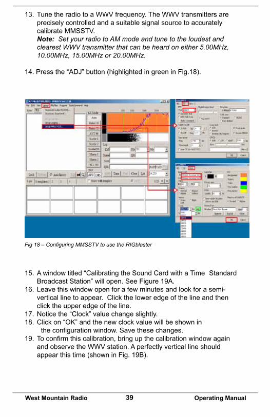
14. Press the “ADJ” button (highlighted in green in Fig.18).
Fig 18 – Configuring MMSSTV to use the RIGblaster
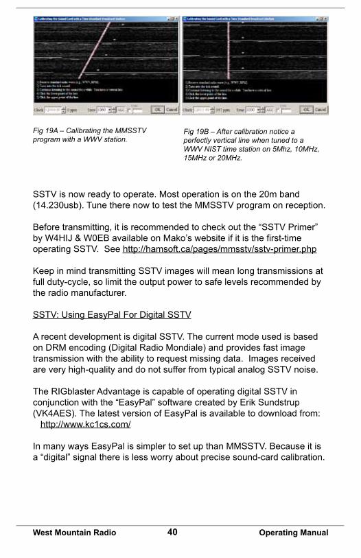
15. A window titled “Calibrating the Sound Card with a Time Standard Broadcast Station” will open. See Figure 19A.16. Leave this window open for a few minutes and look for a semi- vertical line to appear. Click the lower edge of the line and then click the upper edge of the line.17. Notice the “Clock” value change slightly.18.Clickon“OK”andthenewclockvaluewillbeshownin theconfigurationwindow.Savethesechanges.19.Toconfirmthiscalibration,bringupthecalibrationwindowagain and observe the WWV station. A perfectly vertical line should appear this time (shown in Fig. 19B).
40West Mountain Radio Operating Manual
Fig 19A – Calibrating the MMSSTV program with a WWV station.
Fig 19B – After calibration notice a perfectly vertical line when tuned to a WWV NIST time station on 5Mhz, 10MHz, 15MHz or 20MHz.
SSTV is now ready to operate. Most operation is on the 20m band (14.230usb). Tune there now to test the MMSSTV program on reception.
Before transmitting, it is recommended to check out the “SSTV Primer” byW4HIJ&W0EBavailableonMako’swebsiteifitisthefirst-timeoperating SSTV. See http://hamsoft.ca/pages/mmsstv/sstv-primer.php
KeepinmindtransmittingSSTVimageswillmeanlongtransmissionsatfull duty-cycle, so limit the output power to safe levels recommended by the radio manufacturer.
SSTV: Using EasyPal For Digital SSTV
A recent development is digital SSTV. The current mode used is based on DRM encoding (Digital Radio Mondiale) and provides fast image transmission with the ability to request missing data. Images received are very high-quality and do not suffer from typical analog SSTV noise.
The RIGblaster Advantage is capable of operating digital SSTV in conjunction with the “EasyPal” software created by Erik Sundstrup (VK4AES).ThelatestversionofEasyPalisavailabletodownloadfrom: http://www.kc1cs.com/
In many ways EasyPal is simpler to set up than MMSSTV. Because it is a “digital” signal there is less worry about precise sound-card calibration.
41West Mountain Radio Operating Manual
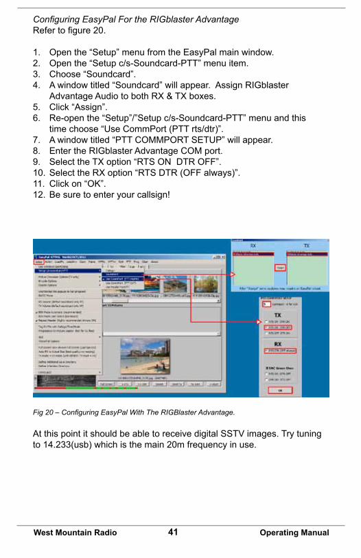
Configuring EasyPal For the RIGblaster AdvantageRefertofigure20.
1. Open the “Setup” menu from the EasyPal main window.2. Open the “Setup c/s-Soundcard-PTT” menu item.3. Choose “Soundcard”.4. A window titled “Soundcard” will appear. Assign RIGblaster Advantage Audio to both RX & TX boxes.5. Click “Assign”.6. Re-open the “Setup”/”Setup c/s-Soundcard-PTT” menu and this time choose “Use CommPort (PTT rts/dtr)”.7. A window titled “PTT COMMPORT SETUP” will appear.8. Enter the RIGblaster Advantage COM port.9. Select the TX option “RTS ON DTR OFF”.10. Select the RX option “RTS DTR (OFF always)”.11.Clickon“OK”.12. Be sure to enter your callsign!
Fig 20 – Configuring EasyPal With The RIGBlaster Advantage.
At this point it should be able to receive digital SSTV images. Try tuning to 14.233(usb) which is the main 20m frequency in use.
42West Mountain Radio Operating Manual
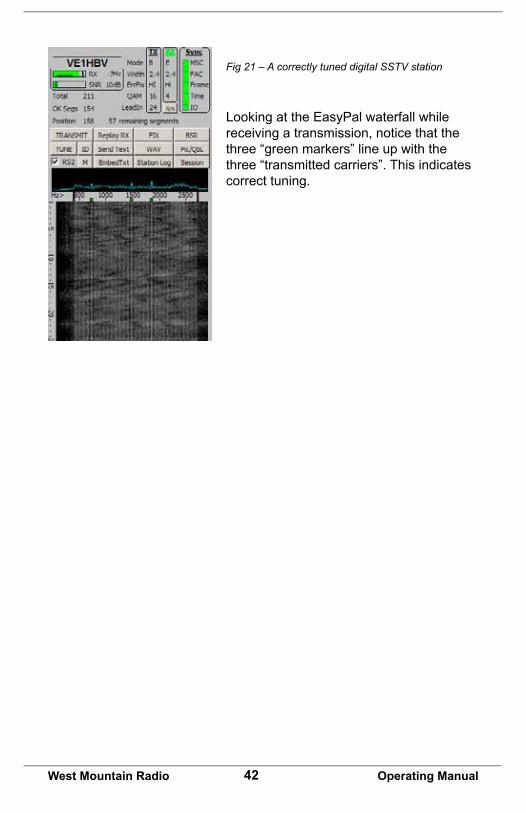
Fig 21 – A correctly tuned digital SSTV station
Looking at the EasyPal waterfall while receiving a transmission, notice that the three “green markers” line up with the three “transmitted carriers”. This indicates correct tuning.
43West Mountain Radio Operating Manual
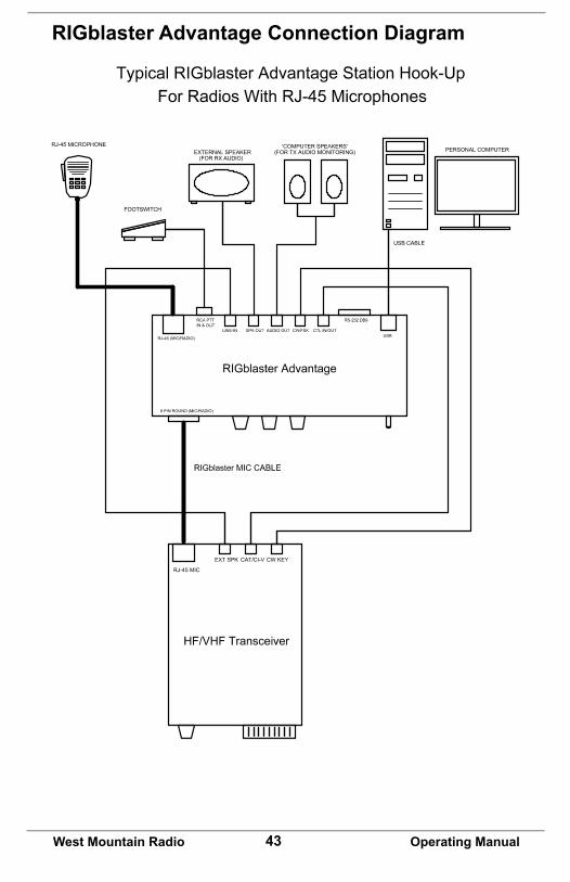
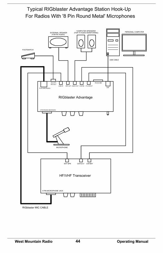
RIGblaster Advantage Connection Diagram
44West Mountain Radio Operating Manual
45West Mountain Radio Operating Manual
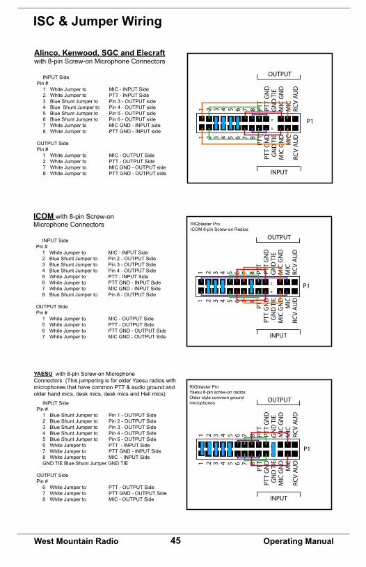
ISC & Jumper Wiring
""
11
22
33
44
55
66
77
88
PTT
PTT
GN
DG
ND
TIE
MIC
GN
DM
ICRC
V AU
D
PTT
PTT
GN
DG
ND
TIE
MIC
GN
DM
ICRC
V AU
D
INPUT
OUTPUT
P1
Alinco, Kenwood, SGC and Elecraftwith 8-pin Screw-on Microphone Connectors
INPUT SidePin # 1 White Jumper to MIC - INPUT Side 2 White Jumper to PTT - INPUT Side 3 Blue Shunt Jumper to Pin 3 - OUTPUT side 4 Blue Shunt Jumper to Pin 4 - OUTPUT side 5 Blue Shunt Jumper to Pin 5 - OUTPUT side 6 Blue Shunt Jumper to Pin 6 - OUTPUT side 7 White Jumper to MIC GND - INPUT side 8 White Jumper to PTT GND - INPUT side
OUTPUT SidePin # 1 White Jumper to MIC - OUTPUT Side 2 White Jumper to PTT - OUTPUT Side 7 White Jumper to MIC GND - OUTPUT side 8 White Jumper to PTT GND - OUTPUT side
""
11
22
33
44
55
66
77
88
PTT
PTT
GN
DG
ND
TIE
MIC
GN
DM
ICRC
V AU
D
PTT
PTT
GN
DG
ND
TIE
MIC
GN
DM
ICRC
V AU
D
INPUT
OUTPUT
ICOM with 8-pin Screw-on Microphone Connectors
INPUT SidePin # 1 White Jumper to MIC - INPUT Side 2 Blue Shunt Jumper to Pin 2 - OUTPUT Side 3 Blue Shunt Jumper to Pin 3 - OUTPUT Side 4 Blue Shunt Jumper to Pin 4 - OUTPUT Side 5 White Jumper to PTT - INPUT Side 6 White Jumper to PTT GND - INPUT Side 7 White Jumper to MIC GND - INPUT Side 8 Blue Shunt Jumper to Pin 8 - OUTPUT Side
OUTPUT SidePin # 1 White Jumper to MIC - OUTPUT Side 5 White Jumper to PTT - OUTPUT Side 6 White Jumper to PTT GND - OUTPUT Side 7 White Jumper to MIC GND - OUTPUT Side
P1
RIGblaster Pro ICOM 8-pin Screw-on Radios
""
11
22
33
44
55
66
77
88
PTT
PTT
GN
DG
ND
TIE
MIC
GN
DM
ICRC
V AU
D
PTT
PTT
GN
DG
ND
TIE
MIC
GN
DM
ICRC
V AU
D
INPUT
OUTPUT
YAESU with 8-pin Screw-on Microphone Connectors (This jumpering is for older Yaesu radios with microphones that have common PTT & audio ground and older hand mics, desk mics, desk mics and Heil mics) INPUT SidePin # 1 Blue Shunt Jumper to Pin 1 - OUTPUT Side 2 Blue Shunt Jumper to Pin 2 - OUTPUT Side 3 Blue Shunt Jumper to Pin 3 - OUTPUT Side 4 Blue Shunt Jumper to Pin 4 - OUTPUT Side 5 Blue Shunt Jumper to Pin 5 - OUTPUT Side 6 White Jumper to PTT - INPUT Side 7 White Jumper to PTT GND - INPUT Side 8 White Jumper to MIC - INPUT Side GND TIE Blue Shunt Jumper GND TIE
OUTPUT SidePin # 6 White Jumper to PTT - OUTPUT Side 7 White Jumper to PTT GND - OUTPUT Side 8 White Jumper to MIC - OUTPUT Side
RIGblaster ProYaesu 8-pin screw-on radiosOlder style common ground microphones
P1
46West Mountain Radio Operating Manual
""
11
22
33
44
55
66
77
88
PTT
PTT
GN
DG
ND
TIE
MIC
GN
DM
ICRC
V AU
D
PTT
PTT
GN
DG
ND
TIE
MIC
GN
DM
ICRC
V AU
D
INPUT
OUTPUT
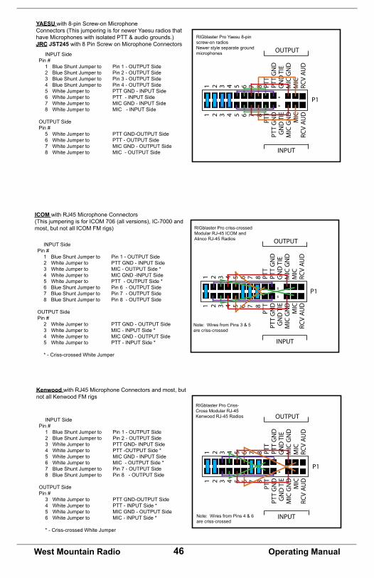
YAESU with 8-pin Screw-on Microphone Connectors (This jumpering is for newer Yaesu radios that have Microphones with isolated PTT & audio grounds.)JRC JST245 with 8 Pin Screw on Microphone Connectors
INPUT SidePin # 1 Blue Shunt Jumper to Pin 1 - OUTPUT Side 2 Blue Shunt Jumper to Pin 2 - OUTPUT Side 3 Blue Shunt Jumper to Pin 3 - OUTPUT Side 4 Blue Shunt Jumper to Pin 4 - OUTPUT Side 5 White Jumper to PTT GND - INPUT Side 6 White Jumper to PTT - INPUT Side 7 White Jumper to MIC GND - INPUT Side 8 White Jumper to MIC - INPUT Side OUTPUT SidePin # 5 White Jumper to PTT GND-OUTPUT Side 6 White Jumper to PTT - OUTPUT Side 7 White Jumper to MIC GND - OUTPUT Side 8 White Jumper to MIC - OUTPUT Side
RIGblaster Pro Yaesu 8-pin screw-on radiosNewer style separate ground microphones
P1
""
11
22
33
44
55
66
77
88
PTT
PTT
GN
DG
ND
TIE
MIC
GN
DM
ICRC
V AU
D
PTT
PTT
GN
DG
ND
TIE
MIC
GN
DM
ICRC
V AU
D
INPUT
OUTPUT
P1
ICOM with RJ45 Microphone Connectors(This jumpering is for ICOM 706 (all versions), IC-7000 and most, but not all ICOM FM rigs)
INPUT SidePin # 1 Blue Shunt Jumper to Pin 1 - OUTPUT Side 2 White Jumper to PTT GND - INPUT Side 3 White Jumper to MIC - OUTPUT Side * 4 White Jumper to MIC GND -INPUT Side 5 White Jumper to PTT - OUTPUT Side * 6 Blue Shunt Jumper to Pin 6 - OUTPUT Side 7 Blue Shunt Jumper to Pin 7 - OUTPUT Side 8 Blue Shunt Jumper to Pin 8 - OUTPUT Side OUTPUT SidePin # 2 White Jumper to PTT GND - OUTPUT Side 3 White Jumper to MIC - INPUT Side * 4 White Jumper to MIC GND - OUTPUT Side 5 White Jumper to PTT - INPUT Side * * - Criss-crossed White Jumper
Note: Wires from Pins 3 & 5 are criss-crossed
RIGblaster Pro criss-crossed Modular RJ-45 ICOM and Alinco RJ-45 Radios
P1
""
11
22
33
44
55
66
77
88
PTT
PTT
GN
DG
ND
TIE
MIC
GN
DM
ICRC
V AU
D
PTT
PTT
GN
DG
ND
TIE
MIC
GN
DM
ICRC
V AU
D
INPUT
OUTPUT
Kenwood with RJ45 Microphone Connectors and most, but notallKenwoodFMrigs
INPUT SidePin # 1 Blue Shunt Jumper to Pin 1 - OUTPUT Side 2 Blue Shunt Jumper to Pin 2 - OUTPUT Side 3 White Jumper to PTT GND- INPUT Side 4 White Jumper to PTT -OUTPUT Side * 5 White Jumper to MIC GND - INPUT Side 6 White Jumper to MIC - OUTPUT Side * 7 Blue Shunt Jumper to Pin 7 - OUTPUT Side 8 Blue Shunt Jumper to Pin 8 - OUTPUT Side OUTPUT SidePin # 3 White Jumper to PTT GND-OUTPUT Side 4 White Jumper to PTT - INPUT Side * 5 White Jumper to MIC GND - OUTPUT Side 6 White Jumper to MIC - INPUT Side *
* - Criss-crossed White Jumper
RIGblaster Pro Criss-Cross Modular RJ-45 KenwoodRJ-45Radios
Note: Wires from Pins 4 & 6 are criss-crossed
47West Mountain Radio Operating Manual
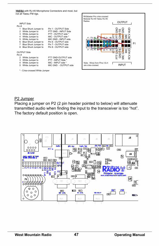
P2 JumperPlacing a jumper on P2 (2 pin header pointed to below) will attenuate transmittedaudiowhenfindingtheinputtothetransceiveristoo“hot”.The factory default position is open.
P1
""
11
22
33
44
55
66
77
88
PTT
PTT
GN
DG
ND
TIE
MIC
GN
DM
ICRC
V AU
D
PTT
PTT
GN
DG
ND
TIE
MIC
GN
DM
ICRC
V AU
D
INPUT
OUTPUT
YAESU with RJ-45 Microphone Connectors and most, but not all Yaesu FM rigs.
INPUT SidePin # 1 Blue Shunt Jumper to Pin 1 - OUTPUT Side 2 White Jumper to PTT GND - INPUT Side 3 White Jumper to PTT - OUTPUT side * 4 White Jumper to MIC - OUTPUT side * 5 White Jumper to MIC GND - INPUT side 6 Blue Shunt Jumper to Pin 6 - OUTPUT side 7 Blue Shunt Jumper to Pin 7 - OUTPUT side 8 Blue Shunt Jumper to Pin 8 - OUTPUT side OUTPUT SidePin # 2 White Jumper to PTT GND-OUTPUT side 3 White Jumper to PTT - INPUT Side * 4 White Jumper to MIC - INPUT side * 5 White Jumper to MIC GND - OUTPUT side
* - Criss-crossed White Jumper
RIGblaster Pro criss-crossed Modular RJ-45 Yaesu RJ-45 Radios
Note: Wires from Pins 3 & 4are criss-crossed
48West Mountain Radio Operating Manual
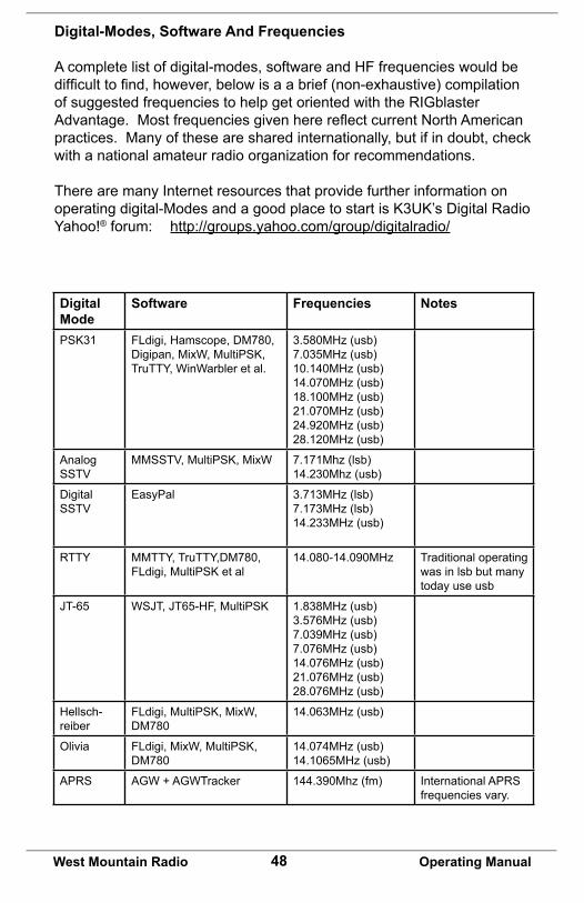
Digital-Modes, Software And Frequencies
A complete list of digital-modes, software and HF frequencies would be difficulttofind,however,belowisaabrief(non-exhaustive)compilationof suggested frequencies to help get oriented with the RIGblaster Advantage.MostfrequenciesgivenherereflectcurrentNorthAmericanpractices. Many of these are shared internationally, but if in doubt, check with a national amateur radio organization for recommendations.
There are many Internet resources that provide further information on operatingdigital-ModesandagoodplacetostartisK3UK’sDigitalRadioYahoo!® forum: http://groups.yahoo.com/group/digitalradio/
Digital Mode
Software Frequencies Notes
PSK31 FLdigi, Hamscope, DM780, Digipan,MixW,MultiPSK,TruTTY, WinWarbler et al.
3.580MHz (usb)7.035MHz (usb)10.140MHz (usb)14.070MHz (usb)18.100MHz (usb)21.070MHz (usb)24.920MHz (usb)28.120MHz (usb)
Analog SSTV
MMSSTV,MultiPSK,MixW 7.171Mhz (lsb)14.230Mhz (usb)
Digital SSTV
EasyPal 3.713MHz (lsb)7.173MHz (lsb)14.233MHz (usb)
RTTY MMTTY, TruTTY,DM780, FLdigi,MultiPSKetal
14.080-14.090MHz Traditional operating was in lsb but many today use usb
JT-65 WSJT,JT65-HF,MultiPSK 1.838MHz (usb)3.576MHz (usb)7.039MHz (usb)7.076MHz (usb)14.076MHz (usb)21.076MHz (usb)28.076MHz (usb)
Hellsch-reiber
FLdigi,MultiPSK,MixW,DM780
14.063MHz (usb)
Olivia FLdigi,MixW,MultiPSK,DM780
14.074MHz (usb)14.1065MHz (usb)
APRS AGW + AGWTracker 144.390Mhz (fm) International APRS frequencies vary.
49West Mountain Radio Operating Manual
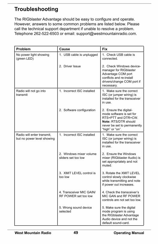
TroubleshootingTheRIGblasterAdvantageshouldbeeasytoconfigureandoperate.However, answers to some common problems are listed below. Please call the technical support department if unable to resolve a problem. Telephone 262-522-6503 or email: [email protected].
Problem Cause FixNo power light showing (green LED)
1. USB cable is unplugged
2. Driver Issue
1. Check USB cable is connected.
2. Check Windows device-manager for RIGblaster Advantage COM port conflictsandre-installdrivers/change COM port if necessary.
Radio will not go into transmit
1. Incorrect ISC installed
2.Softwareconfiguration
1. Make sure the correct ISC (or jumper wiring) is installed for the transceiver in use.
2. Ensure the digital-mode software is set for RTS=PTT and DTR=CW.Note: RTS/DTR should never be set to permanently “high” or “on”.
Radio will enter transmit, but no power level showing
1. Incorrect ISC installed
2. Windows mixer volume sliders set too low
3. XMIT LEVEL control is too low
4. Transceiver MIC GAIN/RF POWER set too low
5. Wrong sound device selected
1. Make sure the correct ISC (or jumper wiring) is installed for the transceiver in use.
2. Ensure the Windows mixer (RIGblaster Audio) is set appropriately and not muted.
3. Rotate the XMIT LEVEL control slowly clockwise while transmitting and note if power out increases.
4. Check the transceiver’s MIC GAN and RF POWER controls are not set too low.
5. Make sure the digital mode program is using the RIGblaster Advantage Audio device and not the default sound-card.
50West Mountain Radio Operating Manual
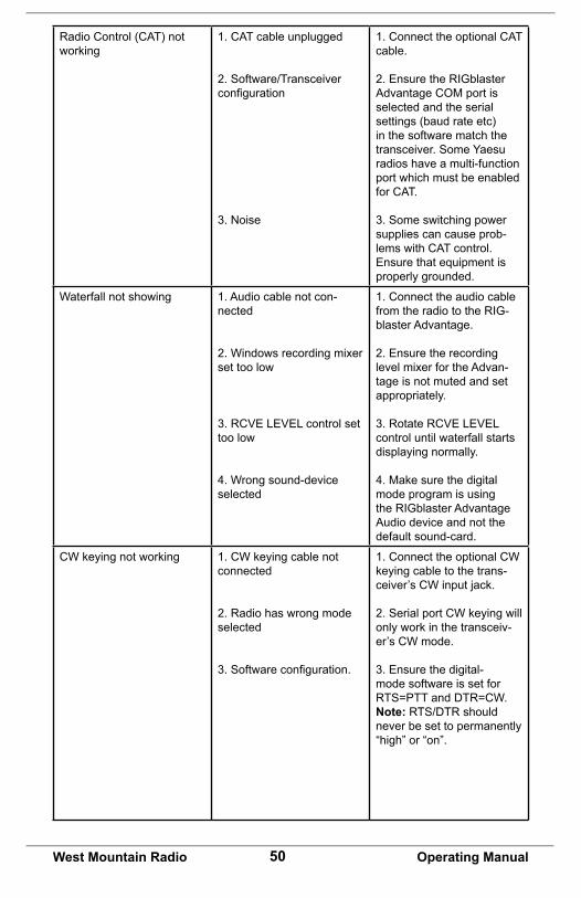
Radio Control (CAT) not working
1. CAT cable unplugged
2. Software/Transceiver configuration
3. Noise
1. Connect the optional CAT cable.
2. Ensure the RIGblaster Advantage COM port is selected and the serial settings (baud rate etc) in the software match the transceiver. Some Yaesu radios have a multi-function port which must be enabled for CAT.
3. Some switching power supplies can cause prob-lems with CAT control. Ensure that equipment is properly grounded.
Waterfall not showing 1. Audio cable not con-nected
2. Windows recording mixer set too low
3. RCVE LEVEL control set too low
4. Wrong sound-device selected
1. Connect the audio cable from the radio to the RIG-blaster Advantage.
2. Ensure the recording level mixer for the Advan-tage is not muted and set appropriately.
3. Rotate RCVE LEVEL control until waterfall starts displaying normally.
4. Make sure the digital mode program is using the RIGblaster Advantage Audio device and not the default sound-card.
CW keying not working 1. CW keying cable not connected
2. Radio has wrong mode selected
3.Softwareconfiguration.
1. Connect the optional CW keying cable to the trans-ceiver’s CW input jack.
2. Serial port CW keying will only work in the transceiv-er’s CW mode.
3. Ensure the digital-mode software is set for RTS=PTT and DTR=CW.Note: RTS/DTR should never be set to permanently “high” or “on”.
51West Mountain Radio Operating Manual
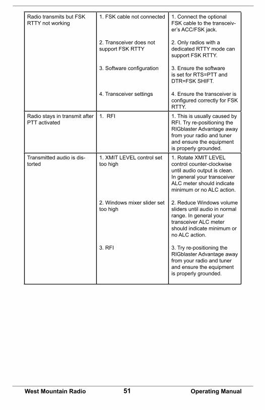
RadiotransmitsbutFSKRTTY not working
1.FSKcablenotconnected
2. Transceiver does not supportFSKRTTY
3.Softwareconfiguration
4. Transceiver settings
1. Connect the optional FSKcabletothetransceiv-er’sACC/FSKjack.
2. Only radios with a dedicated RTTY mode can supportFSKRTTY.
3. Ensure the software is set for RTS=PTT and DTR=FSKSHIFT.
4. Ensure the transceiver is configuredcorrectlyforFSKRTTY.
Radio stays in transmit after PTT activated
1. RFI 1. This is usually caused by RFI. Try re-positioning the RIGblaster Advantage away from your radio and tuner and ensure the equipment is properly grounded.
Transmitted audio is dis-torted
1. XMIT LEVEL control set too high
2. Windows mixer slider set too high
3. RFI
1. Rotate XMIT LEVEL control counter-clockwise until audio output is clean. In general your transceiver ALC meter should indicate minimum or no ALC action.
2. Reduce Windows volume sliders until audio in normal range. In general your transceiver ALC meter should indicate minimum or no ALC action.
3. Try re-positioning the RIGblaster Advantage away from your radio and tuner and ensure the equipment is properly grounded.
RIGblaster Advantage WarrantyRIGblaster Advantage is warranted against failure due to defects in workmanship or materials for one year after the date of purchase from West Mountain Radio. Warranty does not cover damage caused by abuse, accident, misuse, improper or abnormal usage, failure to follow instructions, improper installation, alteration, lightning, or other incidence of excessive voltage or current. If failure occurs within this period, return the RIGblaster Advantage or accessory to West Mountain Radio at your shipping expense. The device or accessory will be repaired or replaced, at our option, without charge, and returned to you at our shipping expense. Repaired or replaced items are warranted for the remainder of the original warranty period. You will be charged for repair or replacement of the RIGblaster Advantage or accessory made after the expiration of the warranty period.
The Compact Disc of Radio Amateur Software Collection is excluded from any and all warranties by West Mountain Radio. Note that the programs have been provided as shareware or freeware by the software authors to the amateur radio community for their use and enjoyment. The DVD is to be used at your own risk.
West Mountain Radio shall have no liability or responsibility to customer or any other person or entity with respect to any liability, loss, or damage caused directly or indirectly by use or performance of the products or arising out of any breach of this warranty, including, but not limited to, any damages resulting from inconvenience, loss of time, data, property, revenue, or profit, or any indirect, special incidental, or consequential damages, even if West Mountain Radio has been advised of such damages.
Except as provided herein, West Mountain Radio makes no express warranties and any implied warranties, including fitness for a particular purpose, are limited in duration to the stated duration provided herein. www.westmountainradio.com 1020 Spring City Drive, Waukesha, WI 53186 tel 262-522-6503 fax 262-522-6504