rfid assisted vehicle positioning in vanets
TRANSCRIPT
Pervasive and Mobile Computing 8 (2012) 167–179
Contents lists available at SciVerse ScienceDirect
Pervasive and Mobile Computing
journal homepage: www.elsevier.com/locate/pmc
RFID assisted vehicle positioning in VANETsEun-Kyu Lee a, Soon Y. Oh b,∗, Mario Gerla a
a Department of Computer Science, University of California, Los Angeles, CA 90095, USAb UtopiaCompression, 11150 Olympic Blvd. # 820, Los Angeles, CA 90064, USA
a r t i c l e i n f o
Article history:Available online 8 July 2011
Keywords:VANETLocalizationRFID
a b s t r a c t
With technological advancement, recent VANET applications such as safe drivingand emergency rescue often demand high position accuracy. Unfortunately, however,conventional localization systems, e.g., GPS, hardly meet new accuracy requirements. Toovercome this limitation, this paper proposes an RFID-assisted localization system. Theproposed system employs the DGPS concept to improve GPS accuracy. A vehicle obtainstwodifferent position data: GPS coordinate from its ownGPS receiver and accurate physicalposition via RFID communication. Then, it computes GPS error and shares it with neighborsto help them correct inaccurate GPS coordinates. To evaluate the proposed system, weconduct extensive experiments both on a simulator and on a real world test-bed. Thesimulation shows that, with the RFID-assisted localization system, vehicles can acquireaccurate position both on a freeway and in an urban area. The results from the test-bed experiments demonstrate that the proposed system is feasible in the real VANETenvironment.
© 2011 Elsevier B.V. All rights reserved.
1. Introduction
In Vehicular Ad hoc Networks (VANETs), vehicles exchange data with each other or with a roadside infrastructure inorder to use various applications from Internet access to safety applications. The VANET applications often assume thatvehicles’ real-time position is provided. This is reasonable because GPS receivers have become popular in vehicles today. Forinstance, navigation applications make use of GPS data for finding their location. However, critical applications that supportsafe driving require more accurate position information so that advanced localization techniques have been proposed tosupport them.
In wireless networks, signal propagation properties, e.g., Received Signal Strength Indicator (RSSI) or Time of Arrival(ToA), have been exploited for localization. Cellular localization [1] uses propagation delay of the signals from transmissiontowers to calculate the ‘‘absolute’’ position. Kukshya et al. [2] use the propagation properties to estimate distance betweenneighbor vehicles and ‘‘relative’’ position. However, due to distortion and interference, a wireless channel is too unstableto guarantee consistent and accurate position. Trilateration, a well-known positioning technique in VANETs to find relativelocation, requires at least three neighbors within the radio range to determine position so that it cannot easily providelocation in sparse traffic environments. Another VANET localization approach, data fusion, calculates position by integratingseveral types of data obtained from different devices, e.g., a GPS, a digital camera, a smart-phone, etc [3,4]. Positionaccuracy in data fusion relies on the number and quality of engaging sensors and pre-training may be necessary for betterperformance. Among existing schemes, Differential GPS (DGPS) improves position accuracy to the level of tens of centimetersin the best case [5]. In road environment, however, its accuracy degrades steeply as a vehicle goes far away from a referencepoint.
∗ Corresponding author. Tel.: +1 310 339 9538.E-mail addresses: [email protected] (E.-K. Lee), [email protected], [email protected] (S.Y. Oh), [email protected] (M. Gerla).
1574-1192/$ – see front matter© 2011 Elsevier B.V. All rights reserved.doi:10.1016/j.pmcj.2011.06.001
168 E.-K. Lee et al. / Pervasive and Mobile Computing 8 (2012) 167–179
In order to provide accurate position in VANET, this paper proposes a novel localization system assisted by Radio-Frequency IDentification (RFID). The main inspiration of our design is the notion of DGPS to improve GPS accuracy. A GPSvehicle, a vehicle equipped with a GPS system, obtains exact position data from an RFID tag on a roadside unit using anRFID reader while driving. Then, it broadcasts the calculated GPS error value to neighbor vehicles via IEEE 802.11 radio. Anon-GPS vehicle, which does not have a GPS system, computes its position using our single peer localization scheme. Whenthe non-GPS vehicle encounters a vehicle having accurate position data, they exchange position and travel information viaRFID and 802.11 radio, respectively. At the end of this process, the non-GPS vehicle can estimate its accurate position fromthe received data.
Our primary contribution is the design of a novel accurate localization system that does not use signal strength orpropagation properties. Moreover, a non-GPS vehicle is able to estimate its own accurate position from a neighbor vehicle.To prove feasibility, we investigate the various parameters of the RFID technology and analyze their impact on accuratepositioning in VANET. We also build a test-bed on a road and conduct experiments driving a car equipped with the RFIDsystem. Simulation and experiment results show that the RFID-assisted localization is feasible on the road and can providesufficient accuracy for critical VANET applications.
The rest of the paper is organized as follows. Section 2 reviews related works: two systems to improve GPS accuracy;and the RFID system and its VANET applications. Section 3 presents the proposed RFID-assisted localization system, whichis followed by its evaluation via simulation in Section 4. In Sections 5 and 6, we describe our test bed set up on a real roadenvironment and demonstrate the experimental results, respectively. Finally, we conclude the paper in Section 7.
2. Related works
2.1. GPS error correction
Differential GPS was used first for a maritime navigation system [6]. DGPS leverages the scientific observation that thedistance to the satellites is so far that GPS receiverswithin a nearby area on the Earth experience the same signal propagationdelay, which leads to the same GPS error. In the DGPS system, a reference point is installed near the coast line, e.g., alighthouse, and calculates GPS error that is the difference between a GPS value received from its own GPS receiver andexact locationmeasured on its installation. GPS error is then delivered to ships passing nearby so that they correct their GPScoordinates. Because there are no obstacles distorting GPS signals in the sea, the reference point and the ships passing nearthe point have the same GPS error. In this way, each ship is able to maintain accurate position. In an urban area, however,tall buildings obstruct and distort GPS signals so that each block shows different GPS error values even within a small area.Thus, the DGPS system cannot guarantee consistent position accuracy. In addition, it is too expensive to be installed in avehicle.
Dead Reckoning (DR) is another GPS error correction technique [7], which is applied when a GPS signal is temporarilyunavailable. Once a mobile node fails to receive GPS signals, it estimates current position based on last recorded locationfrom the GPS system and its mobility information, e.g., speed, orientation, and time. Vehicular applications employ DR insuch placeswhere the GPS signal cannot be reached such as tunnels and indoor parking lots. DR guarantees accurate positiononly for a short time because estimation error quickly accumulates. The estimation error depends on accuracy of on-boardspeed and orientation sensors. As a term of comparison, a speedometer has ±3%– ± 10% error range, and a digital compassor a gyroscope has 10°/s orientation error at maximum.
2.2. RFID system
An RFID system is composed of an RFID tag storing an object identity and an RFID reader that accesses the tag’s data.The difference of the RFID system from traditional bar code is its use of electromagnetic waves for data transmission. TheRFID system operates in various frequency bands and provides corresponding radio ranges. Among them,many applicationsprefer a passive RFID system in Ultra High Frequency (UHF, 860MHz–2.45 GHz) because of low tag price (less than 10 cents)and relatively long radio range (up to approximately 10m). In the passive RFID system, the RFID reader emits RF radiowaveseliciting a signal back from the tag. The RFID tag storing its ID in thememory works without an external power source. Moreprecisely, upon receiving the radio waves, the tag absorbs energy and pumps back the waves modulated with its own IDsignature. This battery-free operation is the most remarkable advantage of the system.
2.3. RFID applications in VANET
The RFID system has been applied to VANET applications in two different ways. First, an RFID tag is attached to a vehicle,and an RFID reader is installed on a roadside. In the Automatic Toll Collection (ATC) system, the RFID reader installed on atoll booth reads the RFID tag on a vehicle when it passes by the booth. The ATC system identifies the passing vehicle andcharges toll road fee automatically. In the Automatic Vehicle Location (AVL) in Vejle, Denmark, RFID tags are attached tothe front bumper of buses, and RFID readers are installed on the road along the bus route in order to identify passing buses.In Edinburgh, UK, RFID tags are attached to buses and emergency vehicles so that RFID readers on the roadside monitor

E.-K. Lee et al. / Pervasive and Mobile Computing 8 (2012) 167–179 169
Fig. 1. The proposed localization system: RF-GPS and single peer localization.
the flow of public transportation and detect emergency situations. Upon receiving this information, a traffic control centercontrols traffic signals to resolve traffic congestion and to prevent car accidents.
In a second type of application, the RFID reader is on the vehicle, whereas RFID tags are on the roadside unit. In RoadBeacon System (RBS) [8], RFID readers on the vehicles gather road information from RFID tags buried under the pavement.In [9], an RFID tag is assumed to have accurate position data, and vehicles with an RFID reader update their locations whenpassing over the tags on the road. Previous research has addressed the issue of installing the RFID reader on a vehiclewithout any verification, but this paper proposes a novel localization system with protocol design and verification withreal implementation and experiments. Moreover, we tackle a new possibility that a vehicle is equipped with both the RFIDtag and the RFID reader, which, we believe, is the future direction of VANET RFID applications.
3. RFID-assisted localization system
3.1. Preliminary
We assume that all the vehicles are equipped with the RFID system and IEEE 802.11 radio (e.g., 802.11p-Dedicated ShortRange Communications [DSRC] [10]), but a GPS receiver is installed only in a fraction of vehicles. The vehicles broadcastpackets to one-hop neighbors via 802.11 radio while the RFID tag/reader set is used for short-ranged RFID communication.A lane on the road is 3mwide, and RFID tags are installed either in roadside units or on the road surface. Fig. 1 illustrates theproposed localization system in a freeway, consisting of RFID assisted GPS and single peer localization. Terminology used inthis paper is as follows.
• Stationary RFID tag is a short radio range (e.g., 3–4 m) passive tag affixed to a roadside unit, e.g., a speed sign, or attachedto the road surface. The tag stores its own absolute position data and transmits it to passing vehicles.
• Mobile RFID tag is a passive tag attached to a vehicle. It stores the vehicle’s ID.• Mobile RFID reader is an interrogator on a vehicle that reads data from either a stationary or a mobile RFID tag.• Reference vehicle is a GPS vehicle that has obtained absolute position data from a stationary RFID tag. It is the mobile
version of a reference point in the DGPS system. After calculating GPS error, it broadcasts the error to neighbors via the802.11 radio.
• GPS coords is coordinate data obtained from a GPS receiver on a vehicle. Abs(olute) coords is coordinate data stored in astationary RFID tag reporting the exact position. Accurate coords (Accurate position data) is a vehicle’s position data witha 3 m error range. Diff(erential) coords is difference between GPS coords and Accurate coords in a vehicle. It representsGPS error at the point.
• Travel data is information of a vehicle’s movement including vehicle ID, Accurate coords, speed, and orientation.
3.2. RF-GPS
RFID assisted GPS (RF-GPS) improves GPS position accuracy by exploiting reference vehicles on a road. Unlike thetraditional DGPS system that uses a fixed reference point, a GPS vehicle becomes a moving reference point temporarily.Upon passing by a stationary RFID tag, the vehicle acquires Abs coords and calculates GPS error value using its own GPScoords. Then, it broadcasts GPS error (Diff coords) to neighbors to support them to correct their GPS coords.
Stationary RFID contact: Stationary RFID tags that store Abs coords in memory are installed on roadside units. Whena (non-) GPS vehicle travels into the radio range of the stationary tag, TS in Fig. 1, the mobile RFID reader on the vehicleobtains Abs coords from TS via RFID communication. Due to the short radio range of RFID communication (3–4 m), only
170 E.-K. Lee et al. / Pervasive and Mobile Computing 8 (2012) 167–179
those vehicles traveling on the lane closest to the road divider (or to the curb) can read the Abs coords from TS . If the vehiclehas a GPS system, then it calculates Diff coords by subtracting Accurate coords from its own GPS coords. The vehicle nowbecomes a reference vehicle (VR in Fig. 1). Note that a non-GPS vehicle cannot be a reference vehicle since it does not haveGPS coords.
Broadcasting: The reference vehicle VR broadcasts Diff coords to one-hop neighbors via the 802.11 radio. Since vehicleswithin the radio range, say, on the freeway, are highly likely to have the same GPS error, a nearby GPS vehicle (VG in Fig. 1)can calculate their Accurate coords using Diff coords received. VR does not repeat Diff coords broadcasting, and VG also doesnot forward it to the neighbors. Furthermore, if the reference vehicle hears a broadcast from another reference vehicle, itdoes not broadcast Diff coords within a short interval even though it obtains Abs coords from a stationary RFID tag. We callthis mechanism as broadcast restriction. Therefore, the Diff coords broadcasting overhead is minimum. However, it is stillpossible that it receives multiple Diff coords from different neighbors. Since two consecutive stationary RFID tags are apartlonger than the radio range (5 km in the evaluation), multiple Diff coords usually come from vehicles encountering the samestationary tag. In this case, VG ignores newer Diff coords if they are the same value; otherwise, it uses the latest informationto calculate its own Accurate coords. We also note that non-GPS vehicles (VN ) within the range cannot compute Accuratecoords since they do not have their own GPS coords.
3.3. Single peer localization
In the basic RF-GPS scheme, a non-GPS vehicle obtains accurate position only via the stationary RFID contact. To enhancepositioning of non-GPS vehicles, we propose a single peer localization scheme. When a non-GPS vehicle encounters a GPSvehicle having Accurate coords, they establish two wireless connections; mobile RFID contact and IEEE 802.11 peer-to-peerlink. Upon receiving data via the connections, the non-GPS vehicle computes its accurate position.
Mobile RFID Contact: When a non-GPS vehicle (VN ) passes a GPS vehicle (VG), VN reads VG’s ID, IDG, via the mobile RFIDcontact: The mobile RFID reader on VN accesses the mobile RFID tag on VG. For future calculation, VN records mobile RFIDcontact information, e.g., vehicle’s ID (IDG) and contact time (TM ), and then they establish peer-to-peer connection via 802.11.
802.11 Peer-to-Peer Connection: The mobile RFID contact triggers an 802.11 peer-to-peer connection: VG broadcasts amessage containing its ID, accurate position, and travel data. Because VG knows that VN is in the vicinity (within 3–4 m),it reduces transmission power to minimize signal interference. Upon receiving the message, VN records current time TGand acquires data tuple, {ID′
G, (xG, yG), SG,OG}, which are the vehicle’s ID, Accurate coords, speed, and orientation of VG. VNverifies the data comparing two IDs, IDG and ID′
G. VN also takes its own travel data {SN ,ON} to compute its Accurate coords(xN , yN ). Define 1T = TG − TM , 1O = OG − ON , and 1L = width of the lane. Then, xN and yN can be evaluated by Eq. (1).
xN = xG + 1T ∗ (SG − SN ∗ cos(1O))
yN = yG − 1T ∗ SN ∗ sin(1O) − 1L.(1)
Dead-Reckoning: Dead-Reckoning is used by a GPS vehicle when GPS signal is not available. It estimates current positionbased on previously recorded position and vehicles speeds over elapsed time and course. In the RF-GPS system, non-GPSvehicles employ DR to compensate for unavailable real-time GPS coordinate data. After obtaining Accurate coords from thestationary RFID contact or the single peer localization, the non-GPS vehicle keeps updating current position using DR. Yet,its error could accumulate quickly and go beyond some satisfactory level. In the following subsection, position accuracy ofRF-GPS and DR is analyzed in detail.
3.4. Position accuracy
In the maritime navigation, DGPS provides accurate position to a ship up to 300 km away from the reference point.The US Department of Transportation estimated error that is 0.67 m per 100 km from the coast-line reference point [11].But, the same level of accuracy is not possible in the VANET scenario. Obstacles on the road affect GPS signal delays, andthus GPS receivers even in a small area could experience different GPS error. The proposed mobile DGPS approach providesaccurate positionusing distributedRFID tags andmoving reference vehicles. TheGPS errormeasuredby the reference vehicleis broadcast only to one-hop neighbor vehicles via 802.11 radio. Thus, propagation of obsolete and erroneous position isprevented. The accuracy level of the mobile DGPS approach is strongly related to the frequency of GPS error measurement,and thus DGPS error can be reduced by pervasive deployment of stationary RFID tags that provide Abs coords. In addition,the traffic pattern is also critical to DGPS error.
Many researchers have investigated and published GPS and DR errors in the literature. Shengbo et al. [12] show thatthe position estimation error in a conventional DR scheme is around 1%–2% of travel distance. According to such error rate,around 20 m of position error occurs in 30 s at 100 km/h vehicle speed. The estimated error rate in a VANET scenario,however, could decrease, because vehicles travel only along the roads and rarely turn their orientation sharply. Specifically,on a freeway, the estimated error rate goes down to 0.3% of travel distance [7]. Say, there would be 2.5 m estimation errorsin 30 s at 100 km/h vehicle speed. We expect 3 m error range in DGPS, which is the width of a lane. At 100 km/h speed, 3 merror occurs after driving 150 m with 2% error rate and 1000 m with 0.3% error rate. Once calculating elapsed time, DR cankeep within 3 m position error for 5.39 and 35.97 s with 2% and 0.3% of error rate, respectively. Similarly, to support less
E.-K. Lee et al. / Pervasive and Mobile Computing 8 (2012) 167–179 171
Table 1Scenario parameters.
Scenario parameter Default value
Number of vehicles 200Percentage of non-GPS vehicles 50%Speed range of vehicles 20–30 m/sInterval of stationary RFID tag 5 km
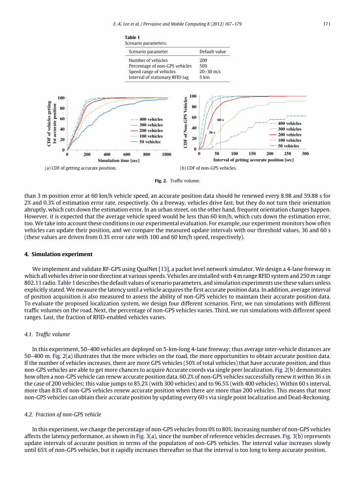
(a) CDF of getting accurate position. (b) CDF of non-GPS vehicles.
Fig. 2. Traffic volume.
than 3 m position error at 60 km/h vehicle speed, an accurate position data should be renewed every 8.98 and 59.88 s for2% and 0.3% of estimation error rate, respectively. On a freeway, vehicles drive fast, but they do not turn their orientationabruptly, which cuts down the estimation error. In an urban street, on the other hand, frequent orientation changes happen.However, it is expected that the average vehicle speed would be less than 60 km/h, which cuts down the estimation error,too.We take into account these conditions in our experimental evaluation. For example, our experimentmonitors howoftenvehicles can update their position, and we compare the measured update intervals with our threshold values, 36 and 60 s(these values are driven from 0.3% error rate with 100 and 60 km/h speed, respectively).
4. Simulation experiment
We implement and validate RF-GPS using QualNet [13], a packet level network simulator. We design a 4-lane freeway inwhich all vehicles drive in one direction at various speeds. Vehicles are installedwith 4m range RFID systemand250m range802.11 radio. Table 1describes the default values of scenario parameters, and simulation experiments use these values unlessexplicitly stated.Wemeasure the latency until a vehicle acquires the first accurate position data. In addition, average intervalof position acquisition is also measured to assess the ability of non-GPS vehicles to maintain their accurate position data.To evaluate the proposed localization system, we design four different scenarios. First, we run simulations with differenttraffic volumes on the road. Next, the percentage of non-GPS vehicles varies. Third, we run simulations with different speedranges. Last, the fraction of RFID-enabled vehicles varies.
4.1. Traffic volume
In this experiment, 50–400 vehicles are deployed on 5-km-long 4-lane freeway; thus average inter-vehicle distances are50–400 m. Fig. 2(a) illustrates that the more vehicles on the road, the more opportunities to obtain accurate position data.If the number of vehicles increases, there are more GPS vehicles (50% of total vehicles) that have accurate position, and thusnon-GPS vehicles are able to get more chances to acquire Accurate coords via single peer localization. Fig. 2(b) demonstrateshowoften a non-GPS vehicle can renew accurate position data. 60.2% of non-GPS vehicles successfully renew itwithin 36 s inthe case of 200 vehicles; this value jumps to 85.2% (with 300 vehicles) and to 96.5% (with 400 vehicles). Within 60 s interval,more than 83% of non-GPS vehicles renew accurate position when there are more than 200 vehicles. This means that mostnon-GPS vehicles can obtain their accurate position by updating every 60 s via single point localization and Dead-Reckoning.
4.2. Fraction of non-GPS vehicle
In this experiment, we change the percentage of non-GPS vehicles from0% to 80%. Increasing number of non-GPS vehiclesaffects the latency performance, as shown in Fig. 3(a), since the number of reference vehicles decreases. Fig. 3(b) representsupdate intervals of accurate position in terms of the population of non-GPS vehicles. The interval value increases slowlyuntil 65% of non-GPS vehicles, but it rapidly increases thereafter so that the interval is too long to keep accurate position.

172 E.-K. Lee et al. / Pervasive and Mobile Computing 8 (2012) 167–179
(a) Probability of getting accurate position in GPS vehicles andnon-GPS vehicles.
(b) Mean and median of renewing accurate position in a non-GPSvehicle.
Fig. 3. Fraction of non-GPS vehicles.
(a) Speed configuration. (b) Cumulative percentage of non-GPS vehicles.
Fig. 4. Speed variables.
4.3. Impact of speed variables
This experiment investigates the effect of vehicle speed on localization performance. We divide speed ranges into threegroups; 15–30, 20–30, and 25–30 m/s. In addition, each group has two different settings: first, all vehicles randomly selectspeed from the given speed, and second lanes are divided into faster lanes and slower lanes (vehicle speed is still selectedfrom the given range). Fig. 4(a) depicts the speed configuration. The lines show the speed ranges, and the small rectangles inthe middle of the lines are the average speed of vehicles. The bars represent standard deviation indicating speed variations.Fig. 4(b) exhibits the average update interval of accurate position in non-GPS vehicles. High speed and large speed variationshorten the update interval since this configuration provides more chances to encounter GPS vehicles.
4.4. Fraction of RFID-enabled vehicle
In this experiment, we assume all vehicles have a GPS system, but an RFID system is installed on a portion of the vehicles.Other parameters are same to those in Table 1. In Fig. 5(a), the performance of RF-GPS degrades as the number of RFID-enabled vehicles decreases. With 20% of RFID-enabled vehicles, performance degrades 60 times compared to the 100% case,mainly because the number of broadcast messages containing Diff coords decreases. This reasoning is enumerated with theresults in Fig. 5(b), showing that the average number of broadcast messages proportionally increases to the number of theRFID-enabled vehicles. The update intervals of Diff coords are also shown in Fig. 5(b) (see the third bars). If the RFID systemis installed on 80% of vehicles, each GPS vehicle receives Diff coords and thus corrects GPS error every 45 s. The resultsimply that RF-GPS can maintain position accuracy even in the GPS deprived zones provided if there are sufficient numbersof RF-GPS vehicles and stationary RFID tags. For example, properly deployed stationary RFID tags in a tunnel can help GPSvehicles maintain accurate position.
5. RFID test-bed experiment
The goal of our test-bed experiments is to prove the feasibility of RFID communication in a highlymobile VANET scenario.We install an RFID reader at the front bumper of a vehicle and place RFID tags on a road. We deploy RFID tags on roadsurface instead of the road side unit because this setting simulates the harshest environment for RFID communication.During experiments, we measure RFID read rate while the vehicle is driving over the RFID tags.

E.-K. Lee et al. / Pervasive and Mobile Computing 8 (2012) 167–179 173
(a) Probability of getting accurate position in GPS vehicles. (b) Messages on RF-GPS.
Fig. 5. Fraction of RFID-enabled vehicles.
Fig. 6. RFID system: reader, reader antenna, and tag.
Table 2Hardware specification of the used RFID system.
RFID reader
Frequency 910–914 MHzRF power 4W EIRPRead distance Less than 5 mModulation ASKRadio access FHSS
RFID reader antennaAngle 60°(3 dB)Gain 6 dBiSize 215(W)× 420(L)× 55(H)
Forward FW Jamie McMaster
RFID tag Data 64bitData rate 256 kbps
5.1. RFID system specification
We select a UHF RFID system because of its long range and fast transmission time. Table 2 summarizes the specificationof the used RFID system. The reader is KIS900RE operating in 900–914 MHz [14]. It provides an anti-collision algorithmfor multiple readers using Frequency-Hopping Spread Spectrum (FHSS) in 200 kHz bandwidth. An RFID reader antennaKIS900AE has 60° of angle and 6 dBi of gain. The EM4222 chip is used in an RFID tag to transmit 64bit data at 256 kbps rate.For anti-collision, each tag gives random jitter, pause time, before sending data out. The maximum pause time is 62.5 ms.Fig. 6 shows the RFID system including a computer for gathering and processing RFID data.

174 E.-K. Lee et al. / Pervasive and Mobile Computing 8 (2012) 167–179
(a) Front view. (b) Side view.
Fig. 7. RFID read area.
Table 3Moving speed of RFID read area (time to pass over a fixed RFID tagwith h = 37.5 cm and θ = 45°).
Speed (km/h) Theoretical value (s) Experiment value (s)
10 0.665 0.36020 0.332 0.18030 0.222 0.12040 0.166 0.09050 0.133 0.07260 0.111 0.06070 0.095 0.05180 0.083 0.04590 0.074 0.040
100 0.067 0.036
5.2. RFID communication in VANET
In the VANET scenario, an RFID reader and an RFID tag encounter during a very short time period since the reader atthe vehicle moves at a very high speed. We define RFID read latency as a required time period during which the readersuccessfully obtains the tag data after it meets a valid tag.
To compute the read latency, we use 68° of an RFID reader angle [9], and Fig. 7 presents the corresponding RFID read areawhere a signal from the RFID reader could reach. The width (x1) and the length (x2) of the area are calculated by Eq. (2).
x1 = 2 × h × tan 34°
x2 =h
tan(56° + θ°)+
htan(56° − θ°)
(2)
where h and θ are the height and the pitch angle of the reader antenna (−56° < θ < 56°), respectively. If h = 37.5 cm andθ = 45°, then we can compute x1 = 58.58 cm and x2 = 185.63 cm. Using these values, the maximum time, during which atag can stay in the moving RFID read area, is derived in terms of vehicle speed as shown in Table 3. The values in the secondcolumn ‘‘Theoretical values’’ are computed by Eq. (2), whereas those in the next column ‘‘Experimental values’’ result fromour experiments. A big gap between two values is mainly attributed that the RFID signal range in the real world (i.e., in theexperiment) is shorter than theoretical values. For instance, x2 value is only 1 m instead of 1.85 m in practice.
Data transmission rate at the RFID tag introduces another issue. According to specification, the tag has 256 kbps data rate,and it takes 0.22 ms to transmit 64bit data. However, in our experiment, the average read latency records 38.89 ms becauseof the pause time at the tag, i.e., the maximum pause time is 62.5 ms. To solve this problem, we propose RFID performanceenhancement technique and antenna setting in the next subsection.
5.3. Laboratory experiment and RFID system installation
To investigate the best setting that enhances RFID performance, we conduct laboratory experiments. We install a readerantenna with h = 30 cm and pitch angle, θ = 30° as shown in Fig. 8.
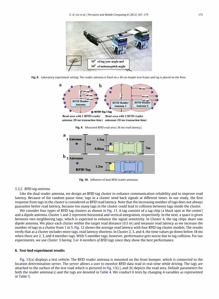
5.3.1. RFID reader antennaTo improve read rate, we install dual RFID antennas as shown in Fig. 9. If one reader antenna is mounted, the read area is
86 cm in width while the width is extended to 130 cmwith dual antennas. Thus, RFID read rate is also expected to increase.As shown in Fig. 10, a vehicle can contact tags even though it deviates from the center of a lane. In the test-bed experiments,dual RFID reader antennas is used; otherwise explicitly stated.
The height h and the angle θ of the reader are also critical for RFID performance, since they determine beam shape anddirection. Through extensive experiments in our laboratory setting, we find that RFID read latency is within 18 ms with0–30 cm height and 20°–40° angle. For simple installation, the reader is placed at 30 cm height and with 30° angle in thetest vehicle.
E.-K. Lee et al. / Pervasive and Mobile Computing 8 (2012) 167–179 175
Fig. 8. Laboratory experiment setting. The reader antenna is fixed on a 30 cm-height iron frame and tag is placed on the floor.
Fig. 9. Measured RFID read area (18 ms read latency).
Fig. 10. Influence of dual RFID reader antennas.
5.3.2. RFID tag antennaLike the dual reader antenna, we design an RFID tag cluster to enhance communication reliability and to improve read
latency. Because of the random pause time, tags in a cluster send back signals at different times. In our study, the firstresponse from tags in the cluster is considered as RFID read latency. Note that the increasing number of tags does not alwaysguarantee better read latency, because too many tags in the cluster could lead to collision between tags inside the cluster.
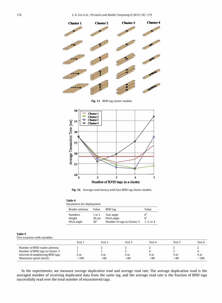
We consider four types of RFID tag clusters as shown in Fig. 11. A tag consists of a tag chip (a black spot at the center)and a dipole antenna. Cluster 1 and 2 represent horizontal and vertical integration, respectively. In the next, a space is givenbetween two neighboring tags, which is expected to enhance the signal sensitivity. In Cluster 4, the tag chips share onedipole antenna. We place each cluster within the target read distance (0.5 m) and measure read latency as we increase thenumber of tags in a cluster from 1 to 5. Fig. 12 shows the average read latency with four RFID tag cluster models. The resultsverify that as a cluster includesmore tags, read latency shortens. In Cluster 2, 3, and 4, the time values go down below 18mswhen there are 2, 3, and 4member tags. With 5member tags, however, performance gets worse due to tag collision. For ourexperiments, we use Cluster 3 having 3 or 4 members of RFID tags since they show the best performance.
6. Test-bed experiment results
Fig. 13(a) displays a test vehicle. The RFID reader antenna is mounted on the front bumper, which is connected to thelocation determination server. The server allows a user to monitor RFID data read in real-time while driving. The tags areattached to the surface of the test road which is pictured in Fig. 13(c), and (b) depicts the read area. Default parameters forboth the reader antenna(s) and the tags are denoted in Table 4. We conduct 6 tests by changing 4 variables as representedin Table 5.
176 E.-K. Lee et al. / Pervasive and Mobile Computing 8 (2012) 167–179
Fig. 11. RFID tag cluster models.
Fig. 12. Average read latency with four RFID tag cluster models.
Table 4Parameters for deployment.
Reader antenna Value RFID tag Value
Numbers 1 or 2 Yaw angle 0°Height 30 cm Pitch angle 0°Pitch angle 30° Number of tags in Cluster 3 1, 3, or 4
Table 5Test scenarios with variables.
Test 1 Test 2 Test 3 Test 4 Test 5 Test 6
Number of RFID reader antenna 1 2 2 2 2 2Number of RFID tags in Cluster 3 1 1 3 4 3 4Interval of neighboring RFID tags 2 m 2 m 2 m 2 m 5 m 5 mMaximum speed (km/h) ∼100 ∼80 ∼80 ∼80 ∼80 ∼100
In the experiments, we measure average duplication read and average read rate. The average duplication read is theaveraged number of receiving duplicated data from the same tag, and the average read rate is the fraction of RFID tagssuccessfully read over the total number of encountered tags.

E.-K. Lee et al. / Pervasive and Mobile Computing 8 (2012) 167–179 177
Fig. 13. Testbed: RFID system, a vehicle, and a road.
6.1. Effect of antenna diversity
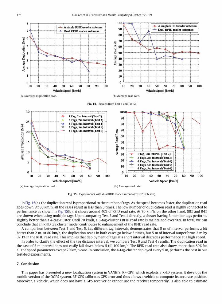
Test 1 and Test 2 share the same configuration except the number of RFID reader antenna. In Fig. 14(a), single and dualantenna systems show similar duplication number and they decline as vehicle speed increases. Furthermore, in Fig. 14(b),average read rates drop rapidly as vehicles’ speed becomes faster. After 40 km/h of speed, the read rates drop to 40%–50%.Unfortunately, we could not find a big difference between them, since the test vehicle travels along the center of the lane.But, as shown in Fig. 10, the dual reader antenna widens the read area so we believe that tag miss is decreased in the realworld.
6.2. Effect of tag multiplicity
With dual RFID reader antennas, we vary the number of member tags in Cluster 3 and the interval between tag clusters,i.e., Test 2–Test 6. The results are shown in Fig. 15.
178 E.-K. Lee et al. / Pervasive and Mobile Computing 8 (2012) 167–179
(a) Average duplication read. (b) Average read rate.
Fig. 14. Results from Test 1 and Test 2.
(a) Average duplication read. (b) Average read rate.
Fig. 15. Experiments with dual RFID reader antenna (Test 2 to Test 6).
In Fig. 15(a), the duplication read is proportional to the number of tags. As the speed becomes faster, the duplication readgoes down. At 80 km/h, all the cases result in less than 5 times. The low number of duplication read is highly connected toperformance as shown in Fig. 15(b); it shows around 40% of RFID read rate. At 70 km/h, on the other hand, 80% and 94%are shown when using multiple tags. Upon comparing Test 3 and Test 4 directly, a cluster having 3 member tags performsslightly better than a 4-tag-cluster. Until 70 km/h, a 3-tag-cluster’s RFID read rate is maintained over 90%. In total, we canconclude that an RFID tag cluster model contributes to enhancement of the RFID read rate.
A comparison between Test 3 and Test 5, i.e., different tag intervals, demonstrates that 5 m of interval performs a bitbetter than 2 m. At 80 km/h, the duplication reads in both cases go below 5 times, but 5 m of interval outperforms 2 m by37.1% in the RFID read rate. This implies that deployment of tags at a short interval degrades performance at a high speed.
In order to clarify the effect of the tag distance interval, we compare Test 6 and Test 4 results. The duplication read inthe case of 5 m interval does not easily fall down below 5 till 100 km/h. The RFID read rate also shows more than 80% forall the speed parameters except 70 km/h case. In conclusion, the 4-tag-cluster deployed every 5 m, performs the best in ourtest-bed experiments.
7. Conclusion
This paper has presented a new localization system in VANETs, RF-GPS, which exploits a RFID system. It develops themobile version of the DGPS system. RF-GPS calibrates GPS error and thus allows a vehicle to compute its accurate position.Moreover, a vehicle, which does not have a GPS receiver or cannot use the receiver temporarily, is also able to estimate
E.-K. Lee et al. / Pervasive and Mobile Computing 8 (2012) 167–179 179
its accurate position with the single peer localization scheme. The proposed RFID-assisted localization system has beenevaluated extensively via simulations and real world experiments. The results from QualNet-based simulations showed theimpact of traffic volume and speed variations on the performance of the RF-GPS system.We also estimated the consequencesof penetration of theGPS systemand the RFID systemover the road. The test-bed experiments focusedmore on the feasibilityof theRFID systemona vehicular environment. In particular,we evaluated the reliability of RFID communication over variousvehicle speed ranges. The results showed that the off-the-shelf commodities could tolerate fast-moving vehicles: An RFIDreader on a vehicle can access data of an RFID tag on road surface while the vehicle drives fast. The simulations and the realworld experiments together show feasibility and performance of the proposed RF-GPS system.
References
[1] A. Varshavsky, M. Chen, E. deLara, J. Froehlich, D. Haehnel, J. Hightower, A. LaMarca, F. Potter, T. Sohn, K. Tang, I. Smith, Are GSM phones the solutionfor localization? in: 7th IEEE Workshop on Mobile Computing Systems and Applications, WMCSA, 2006, pp. 20–28.
[2] V. Kukshya, H. Krishnan, C. Kellum, Design of a system solution for relative positioning of vehicles using vehicle-to-vehicle radio communicationsduring GPS outages, in: IEEE Vehicular Technology Conference—Fall, vol. 2, 2005, pp. 1313–1317.
[3] R. Schubert, M. Schlingelhof, H. Cramer, G. Wanielik, Accurate positioning for vehicular safety applications—the safespot approach, in: IEEE VehicularTechnology Conference—Spring, Dublin, Ireland, 2007.
[4] A. Boukerche, H. Oliveira, E. Nakamura, A. Loureiro, Vehicular ad hoc networks: a new challenge for localization-based systems, in: IEEE ComputerCommunications, vol. 31, 2008, pp. 2838–2849.
[5] N. Drawil, Improving the VANET vehicles’ localization accuracy using GPS receiver inmultipath environments,Master’s Thesis, University ofWaterloo,2007.
[6] Navigation center differential GPS. http://www.navcen.uscg.gov/?pageName=dgpsMain.[7] T. King, H. Fubler, M. Transier, W. Effelsberg, Dead-reckoning for position-based forwarding on highways, in: International Workshop on Intelligent
Transportation, WIT, 2006, pp. 199–204.[8] R.B.S. (RBS), in: http://www.roadbeacon.com/.[9] H. Chon, S. Jun, H. Jung, S. An, Using RFID for accurate positioning, in: International Symposium on GNSS/GPS 2004, 2004.
[10] Standard Specification for Telecommunications and Information Exchange Between Roadside and Vehicle Systems—5 GHz Band Dedicated ShortRange Communications (DSRC) Medium Access Control (MAC) and Physical Layer (PHY) Specifications, September 2003.
[11] 2001 federal radionavigation plan, Tech. Rep., Department of Transportation and Department of Defense, March 2002.[12] Q. Shengbo, D. Keliang, L. Qingli, An effective GPS/DR device and algorithm used in vehicle positioning system, in: IEEE ITS Conference, 2003.[13] Scalable Networs Inc., QualNet. http://www.scalble-networks.com.[14] Kiscom, in: http://www.kiscom.co.kr/.