reverse martensite transformation in iron nanocrystals under severe plastic deformation
TRANSCRIPT
Materials Letters 83 (2012) 183–185
Contents lists available at SciVerse ScienceDirect
Materials Letters
j ourna l homepage: www.e lsev ie r .com/ locate /mat le t
Reverse martensite transformation in iron nanocrystals under severeplastic deformation
A.S. Aronin ⁎, G.E. AbrosimovaInstitute of Solid State Physics RAS, Chernogolovka, Moscow District, 2 Academician Ossipyan str., 142432 Russia
⁎ Corresponding author. Tel.: +7 4965224689; fax: +E-mail address: [email protected] (AS. Aronin).
0167-577X/$ – see front matter © 2012 Elsevier B.V. Aldoi:10.1016/j.matlet.2012.05.107
a b s t r a c t
a r t i c l e i n f oArticle history:Received 17 May 2012Accepted 27 May 2012Available online 8 June 2012
Keywords:NanocrystalsHREMAmorphous alloys
Structure of amorphous Fe80B20 alloy was studied after high‐pressure torsion method. The deformation leads tonanocrystallization with α-Fe particle formation. Although the average size of α-Fe particles does not exceed10 nm, some particles sized of 20 nm were observed as well. These particles consist of α-Fe and γ-Fe regions.The lattices of these regions are in orientation relationship testifying martensite transformation. The martensitetransformation occurring in the largest nanocrystals lead to fragmentation of the nanocrystals.
© 2012 Elsevier B.V. All rights reserved.
1. Introduction
Increasing interest to nanomaterials is determined by their promis-ing physical properties. Crystallization of melt quenching amorphousalloy ribbons is one of the techniques of producing nanocrystallinealloys. Among such amorphous nanocrystalline alloys of special signifi-cance are iron-based alloys with pronounced magnetic properties.Some recent papers have reported on nanocrystallizaton of amorphousalloys occurring under severe plastic deformation (SPD) [1–4]. The SPDtechnique allows achieving the nanocrystalline state in alloys in whichit cannot be done by traditional methods [4]. In [5] the authors considerthe mechanisms of SPD-induced evolution of nanostructures. The pre-sent paper addresses experimental investigation of deformation-induced evolution of nanostructure, the feasibility of deformationfragmenting of nanocrystals and deformation-induced phase transfor-mations in nanocrystals.
2. Materials and methods
Samples of amorphous Fe80B20 alloy were prepared as ribbons byrapid melt quenching. They were subjected to severe plastic deforma-tion using the high‐pressure torsion method at Р=4 GPa and 200 °С.The sample was placed between Bridgman anvils, the upper one ro-tating during deformation. The deformation made up to 15 rotations.The structure of regions located at 1 mm from the sample center wasinvestigated.
7 4965228160.
l rights reserved.
3. Results and discussion
The structure of the deformed sample is composed of an amor-phous matrix and matrix-distributed iron crystals. The nanocrystallattice parameter corresponds to the lattice of pure iron. In accor-dance with the phase equilibrium diagram, boron is practically iron-insoluble [6]. However, the situation can be different for nanocrystals.The solubility of boron in BCC iron, produced by rapid quenchingtechnique can amount to 12 at% [7]. Since boron can dissolve in theiron lattice by the substitution as well as interstitial mechanisms, itssmall concentrations have no effect on the lattice parameter. There-fore, in principle, the nanocrystals observed can appear as a solid so-lution of boron in iron.
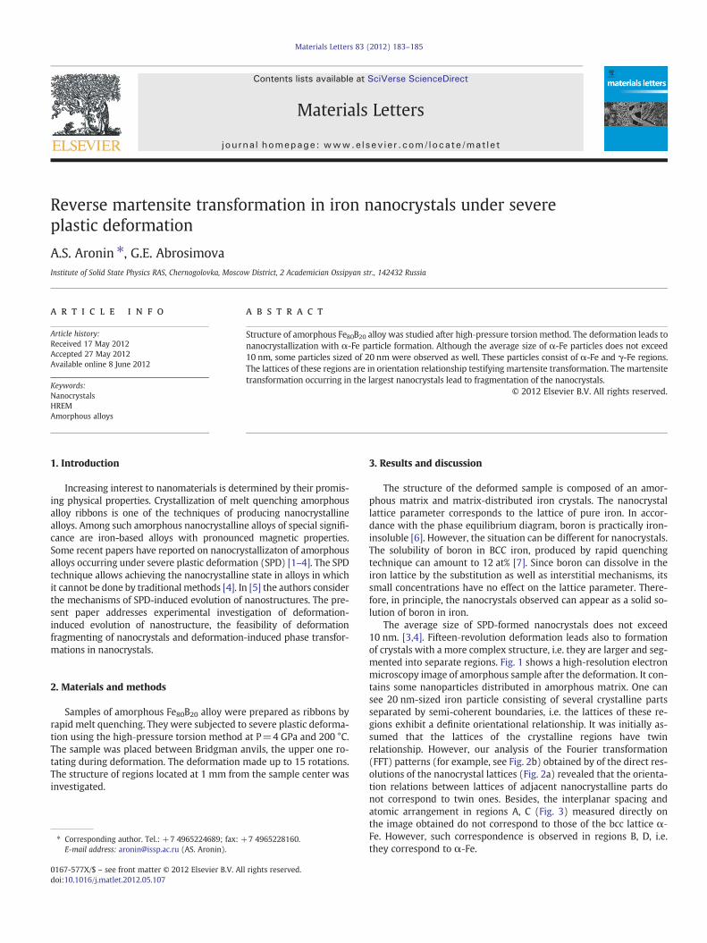
The average size of SPD-formed nanocrystals does not exceed10 nm. [3,4]. Fifteen‐revolution deformation leads also to formationof crystals with a more complex structure, i.e. they are larger and seg-mented into separate regions. Fig. 1 shows a high‐resolution electronmicroscopy image of amorphous sample after the deformation. It con-tains some nanoparticles distributed in amorphous matrix. One cansee 20 nm-sized iron particle consisting of several crystalline partsseparated by semi-coherent boundaries, i.e. the lattices of these re-gions exhibit a definite orientational relationship. It was initially as-sumed that the lattices of the crystalline regions have twinrelationship. However, our analysis of the Fourier transformation(FFT) patterns (for example, see Fig. 2b) obtained by of the direct res-olutions of the nanocrystal lattices (Fig. 2a) revealed that the orienta-tion relations between lattices of adjacent nanocrystalline parts donot correspond to twin ones. Besides, the interplanar spacing andatomic arrangement in regions A, C (Fig. 3) measured directly onthe image obtained do not correspond to those of the bcc lattice α‐Fe. However, such correspondence is observed in regions B, D, i.e.they correspond to α‐Fe.
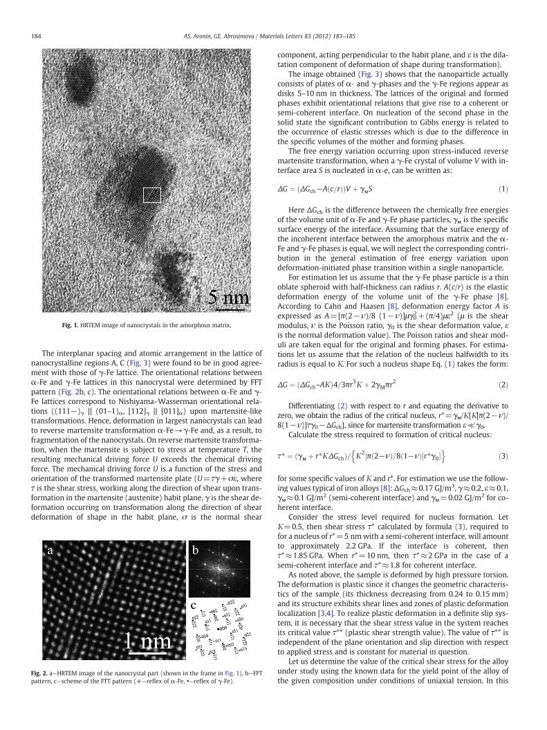
Fig. 1. HRTEM image of nanocrystals in the amorphous matrix.
184 AS. Aronin, GE. Abrosimova / Materials Letters 83 (2012) 183–185
The interplanar spacing and atomic arrangement in the lattice ofnanocrystalline regions A, C (Fig. 3) were found to be in good agree-ment with those of γ‐Fe lattice. The orientational relations betweenα‐Fe and γ‐Fe lattices in this nanocrystal were determined by FFTpattern (Fig. 2b, c). The orientational relations between α‐Fe and γ‐Fe lattices correspond to Nishiyama–Wasserman orientational rela-tions ((111−)γ || (01–1)α, [112]γ || [011]α) upon martensite-liketransformations. Hence, deformation in largest nanocrystals can leadto reverse martensite transformation α‐Fe→γ‐Fe and, as a result, tofragmentation of the nanocrystals. On reverse martensite transforma-tion, when the martensite is subject to stress at temperature T, theresulting mechanical driving force U exceeds the chemical drivingforce. The mechanical driving force U is a function of the stress andorientation of the transformed martensite plate (U=τγ+σε, whereτ is the shear stress, working along the direction of shear upon trans-formation in the martensite (austenite) habit plane, γ is the shear de-formation occurring on transformation along the direction of sheardeformation of shape in the habit plane, σ is the normal shear
Fig. 2. a—HRTEM image of the nanocrystal part (shown in the frame in Fig. 1), b—FFTpattern, c—scheme of the FTT pattern (+—reflex of α‐Fe, •—reflex of γ‐Fe).
component, acting perpendicular to the habit plane, and ε is the dila-tation component of deformation of shape during transformation).
The image obtained (Fig. 3) shows that the nanoparticle actuallyconsists of plates of α‐ and γ‐phases and the γ‐Fe regions appear asdisks 5–10 nm in thickness. The lattices of the original and formedphases exhibit orientational relations that give rise to a coherent orsemi-coherent interface. On nucleation of the second phase in thesolid state the significant contribution to Gibbs energy is related tothe occurrence of elastic stresses which is due to the difference inthe specific volumes of the mother and forming phases.
The free energy variation occurring upon stress-induced reversemartensite transformation, when a γ‐Fe crystal of volume V with in-terface area S is nucleated in α‐e, can be written as:
ΔG ¼ ΔGch−A c=rð Þð ÞV þ γмS ð1Þ
Here ΔGch is the difference between the chemically free energiesof the volume unit of α‐Fe and γ‐Fe phase particles, γм is the specificsurface energy of the interface. Assuming that the surface energy ofthe incoherent interface between the amorphous matrix and the α‐Fe and γ‐Fe phases is equal, we will neglect the corresponding contri-bution in the general estimation of free energy variation upondeformation-initiated phase transition within a single nanoparticle.
For estimation let us assume that the γ‐Fe phase particle is a thinoblate spheroid with half-thickness сan radius r. A(c/r) is the elasticdeformation energy of the volume unit of the γ‐Fe phase [8].According to Cahn and Haasen [8], deformation energy factor А isexpressed as А=[π(2−ν)/8 (1−ν)]μγ0
2+(π/4)με2 (μ is the shearmodulus, ν is the Poisson ratio, γ0 is the shear deformation value, εis the normal deformation value). The Poisson ratios and shear mod-uli are taken equal for the original and forming phases. For estima-tions let us assume that the relation of the nucleus halfwidth to itsradius is equal to К. For such a nucleus shape Eq. (1) takes the form:
ΔG ¼ ΔGch–АКð Þ4=3πr3К þ 2γMπr2 ð2Þ
Differentiating (2) with respect to r and equating the derivative tozero, we obtain the radius of the critical nucleus, r*=γм/К{К[π(2−ν)/8(1−ν)]τγ0−ΔGch}, since for martensite transformation ε≪γ0.
Calculate the stress required to formation of critical nucleus:
τ� ¼ γм þ r�КΔGchð Þ= К2 π 2−νð Þ=8 1−νð Þ�r�γ0½ �n o
ð3Þ
for some specific values of К and r*. For estimation we use the follow-ing values typical of iron alloys [8]: ΔGch≈0.17 GJ/m3, γ≈0.2, ε≈0.1,γм≈0.1 GJ/m2 (semi-coherent interface) and γм=0.02 GJ/m2 for co-herent interface.
Consider the stress level required for nucleus formation. LetК=0.5, then shear stress τ* calculated by formula (3), required tofor a nucleus of r*=5 nmwith a semi-coherent interface, will amountto approximately 2.2 GPa. If the interface is coherent, thenτ*≈1.85 GPa. When r*=10 nm, then τ*≈2 GPa in the case of asemi-coherent interface and τ*≈1.8 for coherent interface.
As noted above, the sample is deformed by high pressure torsion.The deformation is plastic since it changes the geometric characteris-tics of the sample (its thickness decreasing from 0.24 to 0.15 mm)and its structure exhibits shear lines and zones of plastic deformationlocalization [3,4]. To realize plastic deformation in a definite slip sys-tem, it is necessary that the shear stress value in the system reachesits critical value τ** (plastic shear strength value). The value of τ** isindependent of the plane orientation and slip direction with respectto applied stress and is constant for material in question.
Let us determine the value of the critical shear stress for the alloyunder study using the known data for the yield point of the alloy ofthe given composition under conditions of uniaxial tension. In this
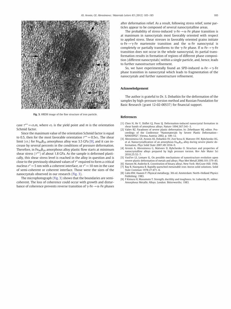
Fig. 3. HREM image of the fine structure of iron particle.
185AS. Aronin, GE. Abrosimova / Materials Letters 83 (2012) 183–185
case τ**=στm, where στ is the yield point and m is the orientationSchmid factor.
Since the maximum value of the orientation Schmid factor is equalto 0.5, then for the most favorable orientation τ**=0.5στ. The shearlimit (στ) for Fe80В20 amorphous alloy was 3.5 GPa [9], and it can in-crease by several percents in the conditions of pressure deformation.Therefore, in Fe80В20 amorphous alloy plastic flow starts at minimumshear stress (τ**) of about 1.8 GPa. As the sample is deformed plasti-cally, this shear stress level is reached in the alloy in question and isclose to the previously obtained values of τ* required to form a criticalnucleus r*=5 nm with a coherent interface, or r*=10 nm in the caseof semi-coherent or coherent interface. Those were the sizes of thenanocrystals observed in our research (Fig. 3).
The microphotograph (Fig. 3) shows that the boundaries are semi-coherent. The loss of coherence could occur with growth and distur-bance of coherence prevents reverse transition of γ‐Fe→α‐Fe phases
after deformation relief. As a result, following stress relief, some par-ticles appear to be composed of several nanocrystalline areas.
The probability of stress-induced γ‐Fe→α‐Fe phase transition isat maximum in nanocrystals most favorably oriented with respectto applied stress. Shear stresses in favorably oriented grains initiateα‐Fe→γ‐Fe martensite transition and the α‐Fe nanocrystal iscompletely or partially transforms to the γ‐Fe phase. If α‐Fe→γ‐Fetransition does not occur in the whole nanocrystal, its partial trans-formation results in formation of regions of different phase composi-tion (different nanocrystals) within a single particle, and, hence, leadsto further nanostructure refinement.
So, we have experimentally found an SPD-induced α‐Fe→γ‐Fephase transition in nanocrystal which leads to fragmentation of thenanocrystals and further nanostructure refinement.
Acknowledgement
The author is grateful to Dr. S. Dobatkin for the deformation of thesamples by high‐pressure torsion method and Russian Foundation forBasic Research (grant 12-02-00537) for financial support.
References
[1] Chen H, He Y, Shiflet GJ, Poon SJ. Deformation-induced nanocrystal formation inshear bands of amorphous alloys. Nature 1994;367:541–3.
[2] Valiev RZ. Paradoxes of severe plastic deformation. In: Zehetbauer MJ, editor. Pro-ceedings of the Conference “Nanomaterials by Severe Plastic Deformation—NANOSPD2”, Vienna, Austria; 2002. p. 109–12.
[3] Abrosimova GE, Aronin AS, Dobatkin SV, Zver'kova II, Matveev DV, Rybchenko OG,et al. Nanocrystallization of an amorphous Fe80B20 alloy during severe plastic de-formation. Phys Solid State 2007;49:1034–9.
[4] Aronin A, Abrosimova G, Matveev D, Rybchenko O. Structure and properties ofnanocrystalline alloys prepared by high pressure torsion. Rev Adv Mater Sci2010;25:52–7.
[5] Vasil‘ev LS, Lomaev IL. On possible mechanisms of nanostructure evolution uponsevere plastic deformation of metals and alloys. Phys Met Metall 2006;101:379–85.
[6] Hansen M, Anderko K. Constitution of binary alloys. New York: McGraw-Hill; 1958.[7] Ray R, Hasegawa R. Rapidly quenched metastable iron–boron solid solutions. Solid
State Commun 1978;27:471–6.[8] Cahn RW, Haasen P. Physical metallurgy. 3th ed. Amsterdam: North–Holland Physics
Publishing; 1983.[9] F Kimura H, Masumoto T. Strength, ductility and toughness. In: Luborsky FL, editor.
Amorphous Metallic Alloys. London: Bitterworths; 1983.