rev-2015-03-16 residential blower door and gauge testing · residential blower door and gauge...
TRANSCRIPT

Retrotec Inc.
Residential
Blower Door and Gauge
Testing
rev-2015-03-16

Page 2 of 80 ©Retrotec Inc. 2014
Copyright © 2014 Retrotec Inc.,
All rights reserved.
This document contains materials protected under International and Federal Copyright Laws. No part of this book may be reproduced or transmitted in any form or by any means, electronic or mechanical, including photocopying, recording, or by any information storage and retrieval system without express written permission from Retrotec Inc.
Retrotec makes no warranties with respect to this documentation and disclaims any implied warranties of merchantability, quality, or fitness for any particular purpose. The information in this document is subject to change without notice. Retrotec reserves the right to make revisions to this publication without obligation to notify any person or entity of any such changes.
DucTester, Infiltrometer, FanTestic are Trademarks of Retrotec Inc. Other trademarks or brand names mentioned herein are trademarks or registered trademarks of their respective owners.
Table of Contents
..................................................................................................................................................... 1
Residential ..................................................................................................................................... 1
Blower Door and Gauge ................................................................................................................ 1
Testing .......................................................................................................................................... 1
1. Air leaks when there is a pressure difference across a hole ................................... 6
1.1 Pressure differences you will see in a home ........................................................................ 6
1.1.1. Stack pressure is the major force in energy loss ................................................................ 6
1.1.2. Wind pushes air into and pulls air out of buildings ............................................................ 6
1.1.3. Exhaust mechanically removes energy but at least it can be controlled ........................... 7
1.1.4. Leaky ducts and imbalanced systems cause pressure differences ..................................... 7
1.2 Where Houses Leak ............................................................................................................ 7
1.3 Warm Moist Air does damage in walls ................................................................................ 8
1.4 What Does Air Leakage Cost? ............................................................................................. 8
1.5 How Blower Doors Measure Air Leakage ............................................................................ 9
1.6 Reduce causes of Bias pressure to get good test results ...................................................... 9
1.7 Reduce uncertainty in results by taking lots of readings .................................................... 11
2. Preparing a Building for Air Leakage Testing ......................................................... 12
2.1 First considerations .......................................................................................................... 12
2.2 Preparation Checklist ....................................................................................................... 13
2.3 Preparation of Intentional Openings ................................................................................. 14
2.3.1. Select a Doorway .............................................................................................................. 14
2.3.2. Windows and Doors .......................................................................................................... 15

Page 3 of 80
2.3.3. Exhausts and Intakes ......................................................................................................... 16
2.4 Other Precautions ............................................................................................................ 18
2.4.1. Suspended Ceilings & Fluorescent Light Diffusers ............................................................ 18
2.4.2. Fragile Decorations ........................................................................................................... 19
2.4.3. Flying Floors ...................................................................................................................... 19
2.4.4. Airstreams ......................................................................................................................... 19
2.4.5. Energy Efficient New Homes............................................................................................. 19
2.4.6. Plumbing Traps ................................................................................................................. 19
2.5 Return the House to Pre-Test Condition. .......................................................................... 19
2.6 Site Conditions affect tests so need to be recorded ........................................................... 19
2.6.1. Estimate the Wind Speed ................................................................................................. 19
2.6.2. If needed, measure the inside and outside Temperatures .............................................. 19
2.6.3. Measure and record any Existing Pressure Differentials .................................................. 20
2.6.4. Interaction with Other Site Activities ............................................................................... 20
2.7 Only Measure the Building if required - takes a long time ................................................. 20
2.7.1. Volume needed for air change rates (ACH50) .................................................................. 20
2.7.2. Surface Area needed for normalized leakage areas or permeability ............................... 20
2.7.3. Floor Area needed by some protocols .............................................................................. 20
3. Test a house for total Air Leakage ........................................................................ 21
3.1 Initial set-up ..................................................................................................................... 21
3.2 Take Building Measurements ........................................................................................... 21
3.3 Perform Basic Tests .......................................................................................................... 21
3.3.1. Use the fan in the door panel to pressurize or depressurize the house .......................... 21
3.4 Find Air Leakage Locations by feeling for air flow .............................................................. 21
3.4.1. Locating Leaks without Tools just using your senses ....................................................... 22
3.4.2. Locating Leaks with Chemical Smoke that moves with air currents ................................ 22
3.4.3. Locating Leaks with Theatrical Smoke that oozes out the cracks .................................... 22
3.4.4. Locating Leaks with Infrared Camera to see different temperatures at leak locations ... 22
3.5 Perform a Single Point Test for a Standard or Protocol ...................................................... 22
3.6 Perform a Multi-Point Test ............................................................................................... 23
3.7 Use a Computer to run the multi-point Air Leakage Test ................................................... 24
3.8 Set the gauge to give results for tests based on Standards ................................................ 24
3.9 Standards specify test procedures for air leakage testing .................................................. 25

Page 4 of 80 ©Retrotec Inc. 2014
Notes on Standards ..................................................................................................................... 25
4. Use the Blower Door System to do other tests ..................................................... 28
4.1 Measure Pressure Difference/Air flow between Areas ...................................................... 28
4.2 Test how much Ducts Leak to Outdoors ............................................................................ 29
4.2.1. Measure Duct Leakage to Outdoors by Subtraction for tight houses .............................. 29
4.2.2. Test Duct Leakage to Outdoors by measuring air flow with a Flow Hood ....................... 31
4.2.3. Check to avoid errors in Leakage to Outdoors measurement .......................................... 31
4.2.4. Create a leakage map of the duct system with a Pressure Pan test on each register ..... 32
4.2.5. In a pressurized house, smoke will be pulled quickly into the duct near the leaks ......... 33
4.3 Closed bedroom door test to check pressure balance ....................................................... 33
4.4 Apartment air leakage ...................................................................................................... 34
4.5 Closed door leakage ......................................................................................................... 34
4.6 Measure air handler flow using a blower door .................................................................. 35
4.6.1. Supply Plenum Pressure Matching Method ..................................................................... 36
4.6.2. Using your Blower Door as a Powered Flow Hood ........................................................... 38
4.7 Measure large exhaust and intake flow rates .................................................................... 41
5. Some Tests Require Pressure Gauge Only! ........................................................... 42
5.1 Combustion and Safety Tests ............................................................................................ 42
5.1.1. CAZ Pressure Measurement ............................................................................................. 42
5.1.2. Flue Draft Measurement................................................................................................... 43
5.2 Pressure Balancing and Performance Testing .................................................................... 47
5.2.1. Pressure Imbalances can be Due to Forced Air Systems .................................................. 47
5.2.2. Run a Dominant Duct Leakage Test .................................................................................. 47
5.2.3. See if rooms with Closed Doors get pressurized by air handler running ......................... 47
5.2.4. See if the house or any room gets pressurized when all Interior Doors are closed ......... 48
5.2.5. Measure household exhaust fan flow .............................................................................. 48
5.2.6. Use a pre-built Exhaust Fan Flow Meter instead of building your own box .................... 49
5.2.7. Measure air handler flow with a Flow Grid ...................................................................... 50
Appendix A: Air Tightness Requirements Tables ........................................................ 58
Residential Air Tightness Requirements ....................................................................................... 59
Large Building Air Tightness Requirements .................................................................................. 62
Air Tightness Requirements for Assemblies ................................................................................. 64
Comparison of different Air Leakage Results for the same enclosure ............................................ 64

Page 5 of 80
Appendix B: Calculate flow if required test pressure cannot be reached .................... 67
“n” setting for estimating flow @ pressure during house and duct leakage test ........................... 67
Extrapolation Error for Flow if gauge “n” doesn’t match actual “n” .............................................. 68
Cannot Reach 50 Pa Factors for houses ........................................................................................ 69
Cannot Reach 25 Pa Factors for ducts .......................................................................................... 71
Appendix C: Test Forms ............................................................................................. 72
ASTM Air Leakage Testing Procedure: .......................................................................................... 74
Glossary ...................................................................................................................... 78
rev-2015-03-16 Section 4.6 revised for CEC. Added Russ’s powered flow hood graphics.

Page 6 of 80 ©Retrotec Inc. 2014
1. Air leaks when there is a pressure difference across a hole Air leakage is the infiltration or exfiltration of air from a building. In order for leakage to occur, there must be a hole, and there must be a pressure difference across the hole. Holes, both intentional and unintentional, are unfortunately all too common in buildings.
There are five common issues that create a pressure imbalance: stack pressure, wind, exhaust or supply flows, duct leakage and forced air duct systems.
1.1 Pressure differences you will see in a home
1.1.1. Stack pressure is the major force in energy loss
The stack effect, or stack pressure, comes from the process of hot air rising, and cold air dropping. Typically, warmer inside air tends to rise in a building, and leak out of holes near the top. This air is replaced by colder outside air leaking into holes around the bottom. In warmer climates, this effect can be reversed, as the interior air is cooler, and drops to leak out of the bottom.
Stack pressure can be calculated. The pressure difference experienced is a product of a constant (0.0342), the atmospheric pressure, the building height, and the temperature difference (between the top and bottom of the stack). Essentially, pressure due to stack is proportional to the height, and temperature difference.
Figure 1: Stack pressure is caused by warm air rising and cool air falling.
1.1.2. Wind pushes air into and pulls air out of buildings
When the wind blows, pressures are created where the stream of air is stopped or slowed down by a wall, or some other part of the house. Because air has mass and wind has velocity, when the wind stops moving (as it hits a wall), its momentum turns into pressure. Everyone has felt the pressure on their body when walking on a windy day, or holding their hand out the window of your car. This pressure can be called velocity pressure. A building experiences a positive pressure that pushes against the wall on the windward side and a negative

Page 7 of 80
pressure on the leeward (downwind) side. This has the effect of pushing air in through the holes on the windward side and pulling air out through the holes on the leeward side.
Figure 2: Wind effects on a building; the windward side is affected differently than the leeward side.
Wind pressure is a square function with velocity, which means that when the wind speed doubles the pressure quadruples. That would mean that a 20 mph wind would have four times as much force or pressure on the wall as a 10 mph wind. In a windy environment, this can translate to a significant amount of leakage.
There are two types of pressure that wind creates, stagnation pressure and velocity pressure.
Stagnation pressure- is felt over a large area in the windward side and for several feet from the building and is a result of the air stacking up due to the wind velocity. The wind's velocity is converted to a pressure.
Stagnation pressures are reduced by moving the outdoor pickup point about 15 feet from the building or away from any object that the wind will strike. Place the tube at ground level with a flat plate covering the tube. The pressure field around the building changes from side to side and because the wind direction varies somewhat; using two pickup points at least 20 feet apart will reduce these fluctuations.
Velocity pressure – is caused by the velocity impinging in the end of the tube and converting itself into a pressure at the tube end.
1.1.3. Exhaust mechanically removes energy but at least it can be controlled
Mechanical ventilation systems in a house include ones that exhaust (chimneys and exhaust fans), or supply air (supply fans). These systems can each act to pressurize or depressurize all or parts of a house. If they're not accounted for, these pressure imbalances can force air into and out of leaks in the building envelope.
1.1.4. Leaky ducts and imbalanced systems cause pressure differences
Leaky duct systems can cause pressure imbalances. If the leaks are to the outside (not to conditioned areas of the home), air will be pulled in (through leaks in the supply), or pushed out (through leaks in the return).
Forced air duct systems can contribute to air leakage if they are not correctly balanced. Unfortunately, even a well-designed system can be thrown off from the simple act of closing a door. A closed door can effectively close off a portion of a house from the duct system, limiting the flow of return air and causing a pressure imbalance.
1.2 Where Houses Leak
The attic is a major (if not the major) place to find leaks. Plumbing stacks often have large holes around them, as do chimneys. Beneath the insulation, a number of other leaks can usually be found. The top plate, and wire

Page 8 of 80 ©Retrotec Inc. 2014
penetrations are typically quite leaky. In many cases, a dark attic is brightened by spots of light from the room below; each spot is a leak of air to the attic.
In a typical house, windows and doors occupy a very small percentage of the total leakage in a house. Where the house sits on its foundation is another major source of leakage. Dissimilar materials, usually wood and concrete, are in contact with each other, and are rarely adequately sealed. The bottom portion of the house is also where there are penetrations for plumbing and wiring. These holes are very significant, since negative pressure is usually greatest at the bottom of the house.
Figure 3: Houses typically experience common leak locations, including penetrations into the attic, and where dissimilar building materials meet. (Source: InsulationSmart.com)
Duct systems can also be significant contributors to air leakage. In many cases, these leaks can be the hardest to find and fix. Even small leaks in duct systems can be a major problem, if air is pulled in from polluted or contaminated areas such as carports or damp, moldy crawlspaces.
1.3 Warm Moist Air does damage in walls
In a warm humid climate, even a 1 Pa depressurization can lead to moisture problems, as moist air from outside is drawn into leaky duct systems and into the walls. This moist air then condenses and molds.
1.4 What Does Air Leakage Cost?
FanTestic software from Retrotec can calculate the annual cost for both heating and cooling associated with measured air leakage. The software uses the established Lawrence Berkeley Lab calculation technique to provide a reasonable estimate of typical air leakage.
To calculate annual heating cost
Use the following equation: 26 ×𝐻𝐷𝐷 ×𝐹𝑢𝑒𝑙 𝑃𝑟𝑖𝑐𝑒 ×𝐶𝐹𝑀50 ×0.6
𝑁 ×𝑆𝑒𝑎𝑠𝑜𝑛𝑎𝑙 𝐸𝑓𝑓𝑖𝑐𝑖𝑒𝑛𝑐𝑦
HDD is the annual heating degree days (base 65° F) for the building location
Fuel Price is the cost of fuel in dollars per BTU
N is the Energy Climate Factor from the Climate Information Screen
Seasonal Efficiency is the AFUE rating of the heating system
To calculate annual cooling cost

Page 9 of 80
Use the following equation: 0.026 ×𝐶𝐷𝐷 ×𝐹𝑢𝑒𝑙 𝑃𝑟𝑖𝑐𝑒 ×𝐶𝐹𝑀50
𝑁 ×𝑆𝐸𝐸𝑅
CDD is the cooling degree days (base 70° F) for the building location
Fuel Price is the cost of electricity in dollars per kWh.
N is the Energy Climate Factor from the Climate Information Screen
SEER is the SEER rating for the air conditioner.
1.5 How Blower Doors Measure Air Leakage
All Blower Door Systems consist of a door panel (which temporarily seals an open doorway), and a calibrated fan (which is installed in the panel). Fan speed is controlled either manually (with a manual dial) or automatically (with a digital gauge or specially designed software). A calibrated gauge can display results in a variety of units. Computer software can display similar results but will add more complex data analysis and automatic testing.
See Retrotec's Blower Door Operation Manual for more information on how to install and run a Blower Door system.
Figure 5: A Blower Door can be used to measure whole house leakage from any exterior doorway.
1.6 Reduce causes of Bias pressure to get good test results
Wind blowing across the tip of a tube will cause a significant pressure to appear on the gauge. High fluctuations of bias (baseline) pressures on the gauge (greater than 2 Pa) are a good indication that wind may be a large source of error.
Figure 4: Components of a Blower Door system.

Page 10 of 80 ©Retrotec Inc. 2014
Another thing to notice when the wind is blowing is that it’s very difficult to establish and maintain the test pressure. In windy conditions, the readings on the house/room gauge will fluctuate. For example, when trying to establish 50 Pa, the wind will cause that pressure to go up to 55 Pa and down to 45 Pa, making it very difficult to take a reading.
There are other reasons a large Bias or Baseline pressure can appear on the gauge and these should be eliminated first before assuming wind is causing the problem. If the tube is being moved by the wind, a large rapidly fluctuating pressure will appear but can easily be eliminated by taping or tying down the tube. Next, a large and steady pressure of 10 to 70 Pa will appear if the tube end has touched water and a drop has sealed off the end. Stepping on the tube, or pinching the tube will induce a Bias pressure, so ensure that tubes are not pinched and are located away from walkways.
If air inside the exterior heats up due to the Sun shining on it and if the tube end is above or below the point where it leaves the enclosure, a stack pressure will build up inside the tube that will create a steady pressure that may increase as the tube gets hotter.
Wind velocity is always lower on the leeward side of the building. Moving pickup points away from the windward side reduces the magnitude of wind induced pressures.
Wind velocity increases with height from the ground, so placing our pickup points at ground level reduces the magnitude of fluctuations.
Covering the end of the tube without blocking it helps because the static pressure is reduced. Pop bottles or other containers help. Some testers dig holes to place the tube in. All these methods work. Flat plates on the ground work best because the openings face all directions, and the pickup point is low down. A T works well too.
Combining these methods gives a list you can go by if Baseline pressures are above 2 Pa or you simply want to increase repeatability. Your outdoor pressure pickup tube should:
Be 15 feet from the building
Terminate in a T
Have 2 pickup points at least 20 feet apart attached to either side of the T
Each point should be covered with a flat plate or box
These steps will reduce the magnitude and variation of the Baseline pressures your gauge will see. After that, time averaging or long Baseline recordings will reduce the impact of these wind pressures.

Page 11 of 80
1.7 Reduce uncertainty in results by taking lots of readings
Table 1 shows tests with approximate uncertainties that can result from applying various number of Baseline points, Baseline times, and Time Averaging when taking induced pressures. As the number of Baseline points, the Baseline time, and Time Averaging used for induced pressure readings increase, the uncertainties decrease. For example, repeating the test using the same fan reduces the uncertainty by 5% in each case. Typical uncertainties would be less than half of the values shown, however the table exaggerates the uncertainty trend assuming there are errors while testing with different fans, gauges, and test conditions.
Table 1: Test result uncertainties vary by changing the number of baseline points, the baseline time, and Time Averaging for induced pressures.
Gauge error
Fan error
Baseline points
Baseline time
Baseline variation
Time Averaging for induced pressure
Uncertainty
1% 5% 1 5 s 1.5 Pa 5 s 22%
1% 5% 30 5 s 1.5 Pa 10 s 8.6%
1% 5% 30 10 s 1.5 Pa 10 s 7.9%
1% 5% 30 10 s 1.5 Pa 100 s 6.5%
1% 5% 30 20 s 0.5 Pa 100 s 5.9%

Page 12 of 80 ©Retrotec Inc. 2014
2. Preparing a Building for Air Leakage Testing
Figure 6: There are many things to consider before beginning a Blower Door test - follow the house setup check list to prepare for an air leakage test.
2.1 First considerations
It is important to properly prepare the testing area to protect testing personnel, occupants, and property. Pay special attention to safety, and basic pre-test procedures in order to ensure that a proper, accurate, and efficient job is done.
Safety
A poorly prepared house is a safety hazard. Fire is a danger, as open flames in fireplaces or gas appliances can potentially burn down a house, or asphyxiate testing staff and occupants during the test! Dust, smoke, flue gas, sewer gas, mold spores, insecticides, car exhaust and other polluting chemicals may be drawn into the house during a depressurization test and may require protection for both the tester and the occupants. Make sure these chemicals will not be drawn in during the test or protect the tester and the occupants or perform a pressurization test instead of a depressurization test. The only hazard with pressurization testing is that in cold weather, a large amount of cold air will be blown into one location in the house causing discomfort and perhaps freezing house plants.
Accuracy
Testing is meaningless if the results are not accurately recorded. A properly prepared house and equipment, as well as knowledge of the equipment and procedures, will provide more accurate results.
Consistency
Testing methods and house preparation must be consistent, in order to make test results comparable. This is particularly important during retrofitting, as it is important to know how a house performs before and after a retrofit.

Page 13 of 80
Avoid Mess and Trouble
Extensive repair and cleaning costs can result from a poorly prepared enclosure. Ceiling tiles and other loose objects can all be damaged by the airflow created during a test. Watch out for fireplace soot especially.
Speak with the owner/occupants
Before beginning any preparation or testing, always explain to the occupants the testing procedure and what needs to be done. In most cases, access will be required to all areas of the house or enclosure. Advanced warning to the owner/occupants will allow them to protect valuables, and make arrangements for their time. In all cases, the test requires that all exhaust fans be off during the test, including turning the furnace/air conditioner off for the few minutes while the test is being conducted.
It is important that the homeowner not turn anything back on while the test is being performed without checking with testing staff first.
2.2 Preparation Checklist
Use the House Preparation Checklist on every test to ensure all preparation and safety checks are made on each test. Review the checklist afterwards to ensure the house is returned to its original condition.
Table 2: House Preparation Checklist
Before After Task Notes
House envelope preparation
Select most appropriate doorway to install the Blower Door system
Close all exterior doors (except test doorway)
Door to basement, open if conditioned, close if not
Close all windows, storms, and skylights
Close all attic accesses inside the house
Seal any dog or cat doors with tape or grill mask
Close any fireplace dampers
Inside house preparation
Move any loose items in the direct path of the fan airflow
Open any interior doors to conditioned spaces
Remove fluorescent light & skylight diffusers
Turn off all ceiling fans
Check for any open flames or hot embers Immediately discontinue test if found
Cover any cold ashes
Buffer zones: open to the outside
Attic
Basement if unconditioned
Garage
Porch
Crawl space
Exhaust appliances: turn off

Page 14 of 80 ©Retrotec Inc. 2014
Kitchen & bath exhaust fans
Whole house fan
Clothes dryer
Central vacuum system
Attic & crawl space power ventilators
Other Devices:
Evaporative coolers - turn off
Window a/c units - turn off
Close fresh/outside air vents
Wall furnace - turn off
Central heating & cooling system:
Turn off
Remove filter from grills
Open supply diffusers
If subtraction test: tape over supplies & returns
Close damper over fresh/make-up air intake
Turn off fresh air ventilation system
Water heater:
Turn to pilot position, and leave keys on heater
2.3 Preparation of Intentional Openings
A major test objective is to ensure that the entire conditioned (heated or cooled) space is kept at the same pressure relative to outside during the test. For example, when there is a 50 Pa pressure difference between the front hallway (where the Blower Door is located) and the outdoors, there also needs to be a 50 Pa pressure difference between the back bedroom and the outdoors. In order to achieve this, exterior openings such as windows must be closed and doors to conditioned spaces must be opened.
Establish what the conditioned space of the enclosure is. Conditioned areas must be included in testing, and will need to be pressurized. Unconditioned space should be allowed to match the exterior pressure.
2.3.1. Select a Doorway
It’s important to select the correct doorway to use for testing.
To select a doorway
1. Select a doorway that will fit the specific Blower Door system. If the doorway is abnormally tall or wide, it will be easier to pick a different door rather than try to use cardboard or something makeshift to make the system work.
2. Ensure that there is enough space to work, including assembling the door frame and storing tools and cases, around the door area. Equipment and pressure tubing will need to be kept out of the path of the fan airflow.

Page 15 of 80
3. Watch out for small objects, valuable and loose papers. It may be easier to pick a different door to install the Blower Door in, than to secure the occupant’s personal possessions that will be disturbed by the flow of air.
Figure 7: Properly select doorways in which to install the Blower Door system.
2.3.2. Windows and Doors
2.3.2.1. Windows
Close all windows and skylights, including the outer storm windows. Be especially aware of old hinged windows, which are sometimes poorly latched and may swing open when the pressure changes during the test. If a room or area is meant to be unconditioned, a window must be left open to allow the area to be at the outside air pressure.
2.3.2.2. Exterior Doors
Close all doors leading outside the conditioned space. This includes all exterior doors, and usually includes the door into the garage (as most garages are not conditioned). It sometimes also includes the door to the basement, if the basement is considered unconditioned.
2.3.2.3. Interior Doors
In general, open all interior doors.
Doors leading to rooms which are intentionally cooled or heated should always be open. Typically this will include doors to all rooms which have air supplies, registers, or are insulated from the outside. Closet doors must be open if there is a supply register, attic hatch or other obvious possible leak within. Although, in practice, doors to small linen closets aren’t always opened, in theory all rooms inside the conditioned space should be open. Not opening these spaces could make a difference if there were large holes/leaks inside the closet.
Doors to conditioned attached garages (these are rare) must be opened.
2.3.2.4. Doors to Basements
Doors leading from upstairs into most basements (in northern climates) should be open during the test, as basements are normally conditioned by supply registers, un-insulated ducts, pipes and the un-insulated floor above.

Page 16 of 80 ©Retrotec Inc. 2014
If the basement has no usable living space, supply registers, or has insulated supply ducts or an insulated ceiling, it could be considered unconditioned, in which case the door from upstairs should be shut during the test and a basement window should be open so that the basement is at outdoor pressure.
2.3.2.5. Attic Hatches and Pull-Down Stairs
Attic hatches:
If in the conditioned space, must be closed for the test.
If outside the conditioned space, should be open for the test.
If the attic access is in the ceiling of an unconditioned garage, or outside of the thermal envelope, the access and the main garage overhead door should be open (even though this may not be the normal position). This is especially true if ducts or the air handler are located in the attic above, or in the garage itself. The objective is to ensure that during the test, the same pressure difference is created across all the surfaces of the pressure envelope. This requires that the attic be well ventilated.
2.3.2.6. Garage Door
Large garage doors are usually left closed. However, they must be open if the Blower Door is installed in the main door between the house and the garage. It should also be open if the air handler/furnace is located in the garage, or if there is an attic access in the garage ceiling which is being left open during the test.
2.3.2.7. Unconditioned Crawlspace Vents and Hatches
Unconditioned crawlspace vents and hatches should be open during the test.
2.3.2.8. Skylights
If the skylight has a moveable opening in it, such as a ventilation slot, it should be shut. Some skylights have lay-in translucent plastic panels at ceiling level to diffuse direct sunlight. They are sometimes quite flimsy and brittle and can get pulled down (and broken) during a test. Remove or secure them if required.
2.3.3. Exhausts and Intakes
2.3.3.1. Enclosed Furnace Rooms or Closets
Furnace rooms with separate combustion air intakes from outside (or an attic or crawlspace) are to be considered outside the thermal envelope. Ensure that gas or fuel oil appliances won't fire (for safety), but do not seal the air intakes or flues. The door to the house should be closed.
2.3.3.2. Fireplaces
Glass doors should be closed. If a damper is in place, it should be shut before conducting a test. Even when shut, many dampers will leak a considerable amount of air, often enough to blow ashes out onto the living room floor during depressurization. Clear out the fireplace or lay newspaper sections over the ashes to deflect the air stream.
The fireplace must be cold and completely out. If a house has hot, smouldering coals or ashes, but no fire, the fire will still need to be put out. The best solution is to use a metal ash bucket and take everything outdoors before quenching the coals with water.
For fireplace chimneys without a damper, perform the test without sealing the chimney. It's a big leak that needs to get fixed.
2.3.3.3. Exhaust Fans and Other Air Moving Equipment

Page 17 of 80
Turn everything off that exhausts air from, or blows air into, the house. This includes central air systems, bathroom fans, clothes dryers, and all other vents. It is always best if the homeowner turns them off, so that they are responsible for turning them back on when testing is complete.
Possible exhaust appliances inside of the home:
Kitchen exhaust fans
Downdraft stove top exhaust units
Bathroom exhaust fans
Clothes dryers
Whole house cooling fans (usually located in the hallway ceiling)
Whole house vacuums vented to outdoors
Green-space ventilation fans
2.3.3.4. Exhaust Appliances Outside of the Home
Attic exhaust fans (powered attic ventilators) may throw off the test by depressurizing the house itself. There are two ways to shut exhaust fans down: turn the exhaust fan off with the circuit breaker, or access the attic to adjust the built in thermostat. Although less common, crawlspace ventilators can also cause this problem.
2.3.3.5. Window Air Conditioners
Window air conditioners must be off during the test. Be aware that in a northern climate, air conditioners may be removed in the fall. During summertime testing, consider sealing it off with tape and plastic to get the most representative reading for the winter operating conditions. In the south they are often left in place year-round, and testing can be conducted without any special procedures.
2.3.3.6. Central Air Conditioners
Central air conditioners must be off during the test, including the air handler. If the ducts leak to the outside, the test will be inaccurate if the air handler is running.
2.3.3.7. Cooling Ceiling Fans
It is usually ok to leave ceiling fans on, as they only blow air around in the room. However, in some cases they will accelerate leakage at the ceiling fixture, and will interfere with leak detection if using smoke, so it is recommended that they be turned off.
2.3.3.8. Solar Panel Fans
If the house has solar panels that use air from the home, the fan should not be running during the test.
2.3.3.9. Fuel Fired Appliances
Gas, oil or propane fired furnaces and water heaters must be prevented from firing during the test.
Flame rollout can occur if a vented combustion appliance fires during a depressurization test. This is a very definite fire and safety hazard. Under no circumstances should a test be conducted if measures haven't been taken to prevent appliances from firing!
All vented combustion appliances must be disabled prior to the test, including those outside the thermal envelope being tested (e.g. furnaces and water heaters in buffer zones such as combustion closets, garages,

Page 18 of 80 ©Retrotec Inc. 2014
attics and crawl spaces). Buffer zones are often influenced by pressure changes in the conditioned space and may also be depressurized during the test.
To shut down fuel fired appliances:
For gas systems, turn the appliance's gas valve control from "On" to "Pilot" and leave the pilot light operating while the test is being conducted.
For fuel oil systems (with no gas valve), the main power switch can be thrown, or the fuse can be removed or switched off at the electrical panel.
Although it is best to go to the gas valve or main power switch, furnaces can also be turned off at the thermostat (if it has a Heat - Off - Cool switch). However, be aware that the homeowner may easily turn the furnace back on in the middle of the test if only the switch has been changed. Do not rely on turning the thermostat way down or way up. During a long test, the furnace may still turn on.
In cold weather, it is generally best to turn the thermostat down when first arriving in the home to allow the chimney to flush itself of smoke and for the flue pipe to cool down, as it may need to be temporarily sealed for a new home test per R-2000.
Although rare, sometimes a pilot light will go out during the test and must be re-lit. The furnace pilot is usually easily seen but water heater pilot lights are not. The water heater should fire right up when it is turned back on. If it does not, check that the pilot light is still lit by making a pencil mark on the temperature dial and turning the knob to “HOT”, it should fire immediately. Return the knob to its original setting, and re-light the pilot if necessary.
Never leave a home without ensuring that the systems turned off are reactivated. A simple precaution is to leave car keys or other valuables on top of the unit, which are only reclaimed once the system is back to normal.
2.3.3.10. Airtight Wood Stoves and Wood Furnaces
Airtight wood stoves and wood furnaces must not be operating when conducting a depressurization test, as they can leak smoke into the home. Notify homeowners ahead of time, so that they can ensure that the stove or furnace is not in use.
If the stove is airtight and is still smouldering, but has no fuel in it, close down the combustion air inlets and conduct a pressurization measurement. The potential for accelerating the fire in the stove must be minimized before attempting to depressurize. Disperse any coals in the stove and remove unburned material. When conducting the test, periodically shut off the Blower Door and monitor the firebox. Do not continue if there is any risk of over-firing the stove or starting a chimney fire.
2.4 Other Precautions
2.4.1. Suspended Ceilings & Fluorescent Light Diffusers
Suspended ceilings using T-bars and acoustical tiles may not be able to withstand the 50 Pa of negative pressure created during a multi-reading (point) test. The same is true for the plastic light diffusers under some fluorescent lamps. If the tile ceiling or lights are installed under an older plaster or sheetrock ceiling which has many penetrations through it, remove a tile or light diffuser leading into this cavity before starting the test.
If the suspended ceiling is the thermal envelope (such as in the typical commercial building that has insulation batts on the ceiling), removing a tile may give a very erroneous reading. Perform a single reading test at a lower
Figure 8. Leave your car keys on top of the furnace so you don't forget to reactivate the system.

Page 19 of 80
pressure and don't increase the pressure without keeping an eye on the ceiling. A pressurization test isn't recommended as the tiles may lift up and give erroneous readings.
2.4.2. Fragile Decorations
Ask the homeowner to move any fragile decorations, bric-a-brac, papers etc..., which may get disturbed by the Blower Door airflow. If this is not possible, pick another doorway, or do the entire test under negative pressure only.
2.4.3. Flying Floors
Under negative pressure, a one-piece vinyl floor may rise up if it is over a leaky crawlspace. It is rare, but will significantly affect test results. Testing under positive pressure will prevent this.
2.4.4. Airstreams
Watch out for doors that may slam shut from the pressure changes during a test. In a smaller, tighter home, a sudden increase in negative pressure (from the door shutting) can spike the house pressure, and pull the whole Blower Door out of the doorway. This is highly embarrassing for the tester, and potentially damaging to the homeowner’s floors.
2.4.5. Energy Efficient New Homes
Testing new energy efficient homes for a utility sponsored program, or for a builder who is building energy efficient homes, may require a different house preparation than what is described. For example, the Canadian R-2000 program specifies that furnace, water heater, wood stove and fireplace flues may be sealed for the test. Some intentional ventilation openings such as air-to-air heat exchanger intakes and exhausts may be sealed as well. The objective is to measure the tightness of the building envelope itself, independent of any mechanical systems and intentional openings. Contact the local program administrators for current requirements. Note that extra time is generally needed if openings are to be sealed off.
2.4.6. Plumbing Traps
In many homes, especially newly built ones, considerable amounts of air can flow in through the drainage system (if there is no water in the traps). This should be stopped in new construction by filling the traps with water. Use antifreeze if the home is unheated and if freezing is possible after the testing is complete.
2.5 Return the House to Pre-Test Condition.
Ensure that the building is returned to its original condition before leaving. This includes turning the thermostat and water heater temperature controls to their original setting. Always check to see that furnace, water heater and gas fireplace pilot lights have not been blown out during the test; re-light them if necessary. Remove any temporary seals from fireplaces or other openings sealed during the test. Occupants may not be aware of what was turned off or sealed for the test.
2.6 Site Conditions affect tests so need to be recorded
2.6.1. Estimate the Wind Speed
Wind speed is occasionally required to be measured for certain testing protocols. In most cases, it is simply estimated so that differences in results during retest can be explained.
2.6.2. If needed, measure the inside and outside Temperatures

Page 20 of 80 ©Retrotec Inc. 2014
Temperature measurement is not required for most tests, but there are cases where testing protocols require temperature corrections that can be 1 - 2% in total.
2.6.3. Measure and record any Existing Pressure Differentials
Prior to creating an artificial test pressure there may already be an existing pressure differential due to stack pressures, wind or HVAC operation. Checking pressure differentials across the envelope prior to installing the Blower Door equipment is recommended to identify these pressure sources.
2.6.4. Interaction with Other Site Activities
Construction and other activities require people to move in and out of the building during a leakage test. Accommodations must be made to prevent these activities from spoiling the test. In most cases if the building can remain closed for at least 10 minutes, a single point reading can be taken. If more complex tests are required, complete access to the building may be required for 30 to 90 minutes.
2.7 Only Measure the Building if required - takes a long time
Do not make these measurements unless the test results require these dimensions, because they are very time-consuming. In almost all cases, inside measurements are required.
2.7.1. Volume needed for air change rates (ACH50)
Some protocols require the volume of the building to the measured in order to calculate air-change rates. If this measurement is being made directly from the building, it may take 10 to 60 minutes to complete. It is recommended to complete this prior to installing any equipment. Volumes of the areas between floors are generally included but specific testing standards must be referenced to ascertain what is required.
2.7.2. Surface Area needed for normalized leakage areas or permeability
If normalized leakage areas or permeability is required, then the surface area of the building must be measured. This can take 10-60 minutes, and equipment should not be set up until the measurements are completed. Some testing protocols may require the dimension to be read off building plans, other times it must be measured directly on site. Recording all measurements in an organized way is recommended. The surface area of exterior walls is usually measured as if intermediate floors do not exist.
2.7.3. Floor Area needed by some protocols
In some cases, floor area must be measured in order to calculate specific leakage area that is required by some testing protocols. The floor area is generally measured to the outside walls, and does not include the area of partition walls.

Page 21 of 80
3. Test a house for total Air Leakage
3.1 Initial set-up
Set up the Blower Door system(s) for a total house leakage test. Ensure that the checklist has been followed, and all precautions have been taken before turning on the fan(s). Ensure the tubing is correctly set up.
3.2 Take Building Measurements 3.3 Perform Basic Tests
3.3.1. Use the fan in the door panel to pressurize or depressurize the house
A basic air leakage test can be used to measure the total house leakage in a very short amount of time. It can also be used to locate leaks and to conduct simple zone testing.
To conduct a basic air leakage test
1. Decide whether to pressurize or depressurize the enclosure. 2. Set the door panel and fan up according to the system specifications. 3. Increase the fan speed to achieve a pressure difference of 50 Pa (this is the most common
residential test pressure). 4. Measure the total house leakage.
3.4 Find Air Leakage Locations by feeling for air flow
Once a building has a pressure difference with respect to the outdoors, it can be quite easy to locate air leaks. Sealing the leaks, however, can be more difficult because air leakage often takes creative paths through a building envelope.

Page 22 of 80 ©Retrotec Inc. 2014
Figure 9: Common leak locations in a house.
Where to look for leaks
With the Blower Door running, take a walk around the house. There are a few common leakage sites.
Ductwork
Floor spaces (especially floors over unconditioned spaces, like garages)
Recessed lights
Attic accesses
Chimneys
Wall penetrations
Sliding doors
Rim joists (along foundations, plumbing penetrations)
Soffits, false ceilings
Exhaust fans
3.4.1. Locating Leaks without Tools just using your senses
The simplest and quickest method to locate air leaks is to walk around looking for leaks without any tools at all. If the door to a leaky room is nearly closed, a strong flow of air can be felt flowing through the small opening. Running a hand along a leaky window sill, or beneath leaky pot lights, will quickly determine if those are sites of leaks as well.
3.4.2. Locating Leaks with Chemical Smoke that moves with air currents
Chemical smoke is often a neutral buoyancy smoke, that doesn’t move unless air is flowing in one direction. Release small puffs of smoke near potential leakage sites, and observe the smoke movement.
3.4.3. Locating Leaks with Theatrical Smoke that oozes out the cracks
Theatrical smoke can provide quite a show. It is recommended that theatrical smoke only be used in a pressurization test, since that will force the smoke outdoors, and not draw it into the house.
3.4.4. Locating Leaks with Infrared Camera to see different temperatures at leak
locations
An infrared camera can be used to detect warm and cold locations, which can indicate leakage. Some training is required to operate an infrared camera properly.
3.5 Perform a Single Point Test for a Standard or Protocol
Some protocols require completion of a single-point test in order to be in compliance with the standard. In this case, the test procedure can be based on recording the result observed on a digital gauge.
1. Record all relevant test and building information before beginning the test (i.e. building dimensions, time, temperature, equipment information). A sample test form can be found in Appendix B.
2. Set up the fan to take bias pressures. This will normally be with the fan cover on, with the L4 Flow Range set-up, however follow the procedure set out by the standard for which the test is being run.
3. To collect bias pressure readings, set the gauge for 10s time averaging and put the gauge down on a table, fan case, floor, or somewhere convenient.

Page 23 of 80
4. Wait 20 seconds before taking note of the pressure reading on channel A (“PrA”). Record this value directly into a software program, or on the sample test form to be entered into a software program at a later date.
5. Wait another 20 seconds before taking the next reading, and put this value into the second yellow box in the Bias Pressure row in the software.
6. Continue this process for as many bias pressure readings as the protocol requires (up to 12 individual readings).
7. Uncover the fan and employ the Flow Range that is believed to be the best one for the desired building pressure. This can easily be changed: if the flow reads “TOO LOW” on the gauge switch to a Flow Range with a smaller hole, or if the fan speed is too high, and the target pressure can’t be reached, switch to a Flow Range with a larger hole.
8. Use the gauge or speed control knob to turn on the fan to reach the desired building pressure (usually 50 Pa). Example: On the DM-2 gauge press [Set Pressure] [5] [0] [Enter]
9. Once the fan adjusts to the desired pressure, wait 20 seconds to record the “PrA” value (building pressure), and record the fan pressure “Pr B”, with both readings in Pa. Make sure that the correct Device and Flow Range are selected on the gauge, otherwise the results may be inaccurate. It may be easier to record results with the Hold, @ Pressure, and/or Time Averaging features active (if available).
10. Collect final bias pressures in the same fashion as was done in step 3. Make sure to put the fan back to the position it must be in to follow the guidelines (i.e. covered, or on the L4 Flow Range). Record the bias pressures.
3.6 Perform a Multi-Point Test
Some protocols require completion of a multi-point test in order to be in compliance with the standard. If this is the case, a multi-point test can be completed either manually (with results recorded by hand from the gauge) or automatically with a gauge connected to a computer. The following procedure details how to collect the data by recording results from a digital gauge, with examples using the Retrotec DM-2 gauge.
1. Record the appropriate building and tester information on the sample test form provided in Appendix B.
2. Set up the fan(s) to take bias pressures: this will normally be with the fan cover on, with the L4 Flow Range set-up. However, it is recommended to follow the procedure set out by the standard for which the test is being run.
3. For a multiple fan set-up, make sure all fans are covered, properly connected to their respective gauges, and all gauges are visible to the tester.
4. To collect bias pressure readings, set the gauge(s) for 10s time averaging, and put them down on a table, fan case, floor, or somewhere convenient. Wait 20 seconds before taking note of the pressure reading on channel A, “PrA”. Record this value.
5. Wait another 20 seconds before taking the next reading, and continue in this way until all required bias reading points have been collected.
6. Decide on the range of building pressures that will be required, and how many test points will be taken. This will likely be defined in the protocol/standard being followed.
7. Determine the best Flow Range plate to use, in order to minimize Flow Range changes during the test. You can test this by setting the pressure to both the low end and the high end of the selected building pressure range. If the flow reads “TOO LOW” on the gauge, switch to a smaller Flow Range. If the fan speed reaches 100% without reaching the desired pressure on Channel A, switch to a larger Flow Range.
8. Uncover the fan(s) and attach the Range Ring or Plate believed to be the best one for the building pressure being induced.
9. Use the gauge(s) to turn on the fan(s), in order to reach the first desired building pressure point. Example: To begin testing at 10 Pa, press [Set Pressure] [1] [0] [Enter]

Page 24 of 80 ©Retrotec Inc. 2014
10. Once the fan(s) adjust to the desired pressure, wait 20 seconds, and press [Jog/Hold] twice to hold the reading currently displayed on the screen(s). Record the “PrA” value (building pressure) and the fan pressure “PrB”, both in Pa. If using multiple fans, make sure to indicate which fans experience which pressures.
11. There are two methods to reach different test pressures during a test:
a. With the DM-2, use the Jog function accessed with the Jog/Hold key to increase or decrease the building pressure to be induced. This is ideal if performing a multiple point test with closely spaced points. For instance, if you begin with a 10 Pa building pressure, and want to take the next point at 15 Pa, press [Jog/Hold] [2], this will increase the “PrA” pressure by 5 Pa. Holding the arrow key will increase the pressure continuously by 10 Pa (release the button to stop).
b. Use the Set Pressure function to set the next pressure point. This method is ideal if performing a test with a wide range between points.
12. Once the full range of building pressures and corresponding fan pressures have been recorded, take final bias pressures, in the same fashion as in step 3.
3.7 Use a Computer to run the multi-point Air Leakage Test
Performing automatic tests with a software program provides the same function as performing the tests manually. However, in this case the settings for single or multi-point tests can be preset and a simple click of a button will run the whole test without the need for user input (except for optional covering of the fan(s) during bias pressure readings and any fan range changes required during the test).
Before performing an automatic test, the panels, fans and gauges must be set up properly. After set-up, manually run the fan to make sure you can achieve minimum and maximum pressures required for your automatic test (this will assure that the fan is on the correct Flow Range). Ensure that your gauge is displaying the correct device and correct Flow Range. Press [Mode] to change to the “Flow” mode, so that the gauge displays the maximum and minimum flow. If "TOO LOW" appears on your gauge screen, you must change to a lower Flow Range and try again (if this happens during a test run, the test will pause for you to change the Flow Range).
Ensure that the settings for the test protocol chosen match the guidelines being followed. Any software program that is used should have a way to change settings, or to choose a particular protocol to follow. For instance, in FanTestic, Tools Options Settings tab. See the FanTestic Manual for more information specific to this program.
3.8 Set the gauge to give results for tests based on Standards
In order to meet specific standards, the Retrotec gauge can be configured in a specific way to match the testing standard and have the gauge automatically calculate the required results. Use the instructions below to setup the gauge to calculate results that meet the listed standard.
Configure the Retrotec gauge as indicated in Table 3.
Table 3: Retrotec gauge setup conditions for various standards.
[Setup] Eco-Energy,
Canada Title-24-CA,
USA LEED,
apartment test DS/EN 13829,
& France ATTMA TS-1
n= 0.65 0.6 0.65 0.65 0.65
Surface Area sq ft or m2 sq ft or m2 sq ft m2 m2
Building Volume Unit cu ft or m3 cu ft or m3 cu ft
European Separator No No No Yes No
Page 25 of 80
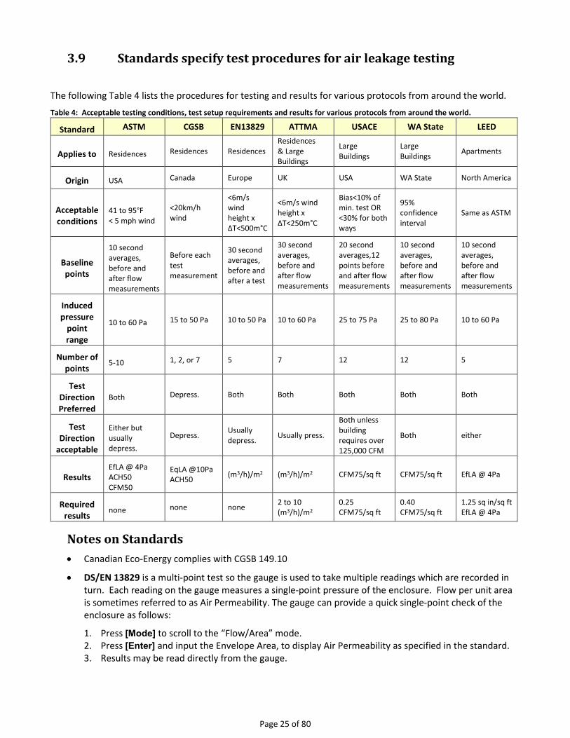
3.9 Standards specify test procedures for air leakage testing
The following Table 4 lists the procedures for testing and results for various protocols from around the world.
Table 4: Acceptable testing conditions, test setup requirements and results for various protocols from around the world.
Standard ASTM CGSB EN13829 ATTMA USACE WA State LEED
Applies to Residences Residences Residences Residences & Large Buildings
Large Buildings
Large Buildings
Apartments
Origin USA Canada Europe UK USA WA State North America
Acceptable conditions
41 to 95°F < 5 mph wind
<20km/h wind
<6m/s wind height x ΔT<500m°C
<6m/s wind height x ΔT<250m°C
Bias<10% of min. test OR <30% for both ways
95% confidence interval
Same as ASTM
Baseline points
10 second averages, before and after flow measurements
Before each test measurement
30 second averages, before and after a test
30 second averages, before and after flow measurements
20 second averages,12 points before and after flow measurements
10 second averages, before and after flow measurements
10 second averages, before and after flow measurements
Induced pressure
point range
10 to 60 Pa 15 to 50 Pa 10 to 50 Pa 10 to 60 Pa 25 to 75 Pa 25 to 80 Pa 10 to 60 Pa
Number of points
5-10 1, 2, or 7 5 7 12 12 5
Test Direction Preferred
Both Depress. Both Both Both Both Both
Test Direction
acceptable
Either but usually depress.
Depress. Usually depress.
Usually press.
Both unless building requires over 125,000 CFM
Both either
Results EfLA @ 4Pa ACH50 CFM50
EqLA @10Pa ACH50
(m3/h)/m2 (m3/h)/m2 CFM75/sq ft CFM75/sq ft EfLA @ 4Pa
Required results
none none none 2 to 10 (m3/h)/m2
0.25 CFM75/sq ft
0.40 CFM75/sq ft
1.25 sq in/sq ft EfLA @ 4Pa
Notes on Standards
Canadian Eco-Energy complies with CGSB 149.10
DS/EN 13829 is a multi-point test so the gauge is used to take multiple readings which are recorded in turn. Each reading on the gauge measures a single-point pressure of the enclosure. Flow per unit area is sometimes referred to as Air Permeability. The gauge can provide a quick single-point check of the enclosure as follows:
1. Press [Mode] to scroll to the “Flow/Area” mode. 2. Press [Enter] and input the Envelope Area, to display Air Permeability as specified in the standard. 3. Results may be read directly from the gauge.

Page 26 of 80 ©Retrotec Inc. 2014
ATTMA: TS-1 is a UK standard is similar to DS/EN 13829. However, it has the Air Leakage Index added, which uses the same units as permeability except it uses the exposed envelope area rather than the total envelope area that permeability requires.
1. Press [Mode] key to scroll to the “Flow/Area” mode 2. Press [Enter] and input either the Envelope Area to display Air Permeability or the Exposed
Envelope Area to display Air Leakage Index, as specified in the standard 3. Press [@ Pressure] to display the Flow @ 50 Pa, Air Changes @ 50 Pa, and either Air Permeability or
Air Leakage Index @ 50 Pa 4. In order to record both Air Permeability and Air Leakage Index, re-enter the different areas from
steps 1 and 2. Results may be read directly from the gauge.
Title-24 is a California standard. It is used to measure duct leakage in CFM at 25 Pa under pressurization, and house leakage at 50 Pa under pressurization.
1. Assess and measure the Conditioned Floor Area CFA in sq ft as specified in the Standard. 2. Press [Mode] to scroll to the “EqLA/Area” mode. 3. Press [Enter] and input the CFA as measured in step 1. 4. Press [@ Pressure] to display the Flow @ 25 Pa. 5. Results for default, heating only analysis may be read. 6. “EqLA/Area” may be read directly from the gauge.
LEED is a multi-point test so the gauge is used to take multiple readings which are recorded in turn. Each reading on the gauge measures a single-point pressure of the enclosure. The gauge can also provide a quick single-point check of the enclosure as follows:
1. Press [Mode] key to scroll to the “Flow/Area” mode. 2. Press [Enter] and input the Envelope Area to display Air Permeability as specified in the standard. 3. Results may be read directly from the gauge.
Table 5: Summary of esults required for various energy efficiency programs around the world.
Standard:
Eco-Energy LEED, apartment
test
USACE DS/EN 13829;
ATTMA TS-1
FR/EN 13829
Northwest ENERGY
STAR
ENERGY STAR
Region: Canada North
America USA Europe/UK France
ID MO OR WA
North America
Pressure Pa Pa Pa Pa Pa Pa Pa
Flow L/s or CFM Off CFM m3/h m3/h CFM CFM
(Flow) @ Pressure
Off n/a 75 Pa 50 Pa 50 Pa 50 Pa 50 Pa
EqLA sq in or cm2 Off sq ft Off Off Off Off
(EqLA) @ Pressure
10 Pa n/a 75 n/a n/a n/a n/a
EfLA, Effective Leakage Area
Off sq in Off Off cm2 Off Off
(EfLA) @ Pressure
n/a 4 Pa n/a n/a 4 Pa n/a n/a
Air Changes /h Off Off /h /h /h /h

Page 27 of 80
(Air Changes) @ Pressure
50 Pa n/a n/a 50 Pa 50 Pa 50 Pa 50 Pa
Flow per Area Off Off CFM/sq ft (m3/h)/m2 (m3/h)/m2 CFM/sq ft CFM/100 sq ft
(Flow per Area) @ Pressure
n/a n/a 75 50 Pa 4 Pa 50 Pa 25 Pa
EqLA per Area cm2/m2 or sq in /100 sq ft
Off Off Off Off Off
Off
(EqLA per Area) @ Pressure
10 Pa n/a n/a n/a n/a n/a n/a
EfLA per Area Off sq in / 100 sq ft
Off Off Off Off Off
(EfLA per Area) @ Pressure
n/a 4 Pa n/a n/a n/a n/a n/a

Page 28 of 80 ©Retrotec Inc. 2014
4. Use the Blower Door System to do other tests In addition to the standard Blower Door tests, it is possible to conduct a number of other tests with a Blower Door system.
4.1 Measure Pressure Difference/Air flow between Areas
Measuring the pressure difference or air flow between areas is often called a zone test. The area under test is called the zone and the other area is called the reference area. A basic zone test is no more than the following:
1. Check Baseline pressure: Have the gauge measure a “Baseline” for at least 60 seconds. 2. Connect the red tube to the “Ref A” (red ) port on the gauge, and place the other end of the tube in
the reference area. 3. Connect the blue tube to the “Input A” (blue) port on the gauge. Place the other end of the tube in
the zone. 4. Channel A, “PrA” on the gauge display, displays the pressure difference between the zone and the
reference area.
It is also possible to measure the pressures in zones that are outside the conditioned space, relative to the house pressure.
To measure zone pressure relative to the house pressure
1. Set up the fan system with a manual speed control and pressurize/depressurize the house to your normal test pressure (typically 50 Pa).
2. Leave the fan running so that the house is at the test (50 Pa) pressure difference to the outside. Disconnect the tubing from the Blower Door when the test pressure has been reached and is stable.
3. Connect a long blue tube to the “Input A” (blue) port on the gauge. Leave the “Ref A” (red) port open to the house.
4. Insert the other end of the blue tube into the zones to be tested. “PrA” will display the difference between the house and the tested zone. If the tested zone has many leaks to the outdoors allowing its pressure to drop to close to the outdoor pressure, you would expect the measured pressure between house and the tested zone to be close to the set test pressure difference between the house and the outdoors (50 Pa). If the zone has few leaks to the outdoors, the measured pressure will be close to 0 Pa since the zone will stay at close to the house pressure.
To measure zone pressure relative to the outdoors
1. Set up the fan system with a manual speed control and pressurize/depressurize the house to your normal test pressure (typically 50 Pa).
2. Leave the fan running so that the house is at the test (50 Pa) pressure difference to the outside. Disconnect the tubing from the Blower Door when the test pressure has been reached and is stable.
3. Connect a long blue tube to the “Input A” (blue) port on the gauge. 4. Connect a long red tube to the “Ref A” (red) port on the gauge, and run the other end outdoors. 5. Insert the other end of the blue tube into the zones to be tested. “PrA” will display the pressure
difference between the tested zone and the outdoors. If the tested zone has many leaks to the outdoors, you would expect the measured pressure to be close to 0 Pa because the zone is more connected to the outdoors. If the zone has few leaks to the outdoors, then you would expect the measured pressure to be close to the set house pressure (50 Pa).
Pressure relief may be needed in any particular room that is pressurized or depressurized by 3 Pa or more, compared to the main body of the house. If combustion appliances are in a depressurized area, even a minor depressurization can interfere with their ability to draft properly.

Page 29 of 80
4.2 Test how much Ducts Leak to Outdoors
A Blower Door can be used to measure “Duct Leakage to Outside” which we prefer to call “Duct Leakage to Outdoors” because “Outside” could be taken to means outside a particular zone which may still be inside the building but the intention here is to measure leakage to the great outdoors.
4.2.1. Measure Duct Leakage to Outdoors by Subtraction for tight houses
Very few State Codes allow this method: Georgia allows it. The entire house enclosure must be finished and tight.
Inaccuracy of this method
This method works reasonably well if the house is 5 ACH50 or less and the ducts are fairly leaky because this method relies on subtracting total house leakage from total house leakage with ducts sealed. Since the house leakage is often 1000 to 5000 CFM but the duct leakage to outdoors must be less than 100 CFM, repeatability is extremely important. Repeatability is typically 1 to 3% depending on the wind and how long readings are taken for. This 1 to 3% translates into 10 to 150 CFM meaning that measuring 100 CFM could be in error by 10 to 150%. Still, if you have a blower door and no DucTester, this method could be useful although adding the DucTester and using the Blower Door gauge would make it inexpensive to add the DucTester.
“If you want to measure how much a cup a coffee weighs. The method I use is - I step on my bathroom scale and weigh myself and then re-do with the cup of coffee. I subtract the 2 measurements to determine the weight of the coffee. How accurate is this method?”
Courtesy of Joe Medosch of the Moultrie Technical College
Modified Blower Door Subtraction Test using a DM-2
1. Setup for a depressurization basic air leakage test. 2. With the air handler off, open all registers, and remove all filters from the HVAC. 3. Seal all exterior combustion air intakes and vents, connected to the ducts. 4. Press [Set Pressure] [50] [Enter] to depressurize the building to -50 Pa (or manually adjust the fan
speed to reach -50 Pa). Press [@ Pressure] until “@50” is displayed or “@25” if results at 25 are required to improve accuracy. Note: the value the [@ Pressure] key displays can be changed in using the Setup key.
5. The measured flow is the Whole House Leakage at 50 Pa or at 25 Pa if “@25” was used. 6. Press [Exit] to turn the Blower Door off. 7. Seal all supply and return registers with Grill Mask. 8. Depressurize the house to -50 Pa again. The measured flow is the Envelope Leakage at 50 Pa. 9. Measure the pressure in the duct system, either at the return or supply plenum, or behind the Grill
Mask at a supply or return register. This is the Duct Pressure. 10. Use the measured Duct Pressure and determine the correction factor from Table 6. 11. Calculate the “Duct Leakage to Outdoors” by subtracting the Envelope Leakage (step 8) from the
Whole House leakage (step 5), and then multiplying that result by the correction factor.
(Whole House CFM50 − Envelope CFM50) × (Correction factor ) = Duct leakage to outdoors at 50 Pa
Table 6: Correction factors for duct pressure
Duct Pressure Subtraction
Correction Factor Duct Pressure Subtraction
Correction Factor
11 6.71 31 2.14

Page 30 of 80 ©Retrotec Inc. 2014
Duct Pressure Subtraction
Correction Factor Duct Pressure Subtraction
Correction Factor
12 6.12 32 2.06
13 5.63 33 1.98
14 5.20 34 1.91
15 4.83 35 1.84
16 4.51 36 1.78
17 4.23 37 1.71
18 3.97 38 1.65
19 3.74 39 1.60
20 3.54 40 1.54
21 3.35 41 1.49
22 3.18 42 1.44
23 3.03 43 1.39
24 2.89 44 1.34
25 2.76 45 1.29
26 2.64 46 1.24
27 2.52 47 1.19
28 2.42 48 1.14
29 2.32 49 1.09
30 2.23 50 1.00
To get duct leakage to a more commonly used 25 Pa, multiply the result by 0.64. Alternatively, set the pressure to 50 Pa for the test but use the “@25Pa” feature to estimate the flow at the desired test pressure. You must still correct this result using the Subtraction Correction Factor.
Example: Whole House leakage is 2200 CFM50; Envelope leakage with ducts sealed off is 2100 CFM50 the duct pressure is 39 Pa giving a correction factor of 1.60. Calculate as follows: 2200-2100 = 100 x 1.60 = 160 which means the ducts leak 160 CFM at 50 Pa. For duct leakage at 25 Pa which is required by most Codes, Multiply 160 X 0.64 = 102 CFM
Improve the accuracy and ease of testing by pressurizing and other methods
Pressurize instead of depressurizing the house because the tape will not be blown off the registers. Retrotec 1000 and 2000 fans don’t require any changes when pressurizing so long as the red tube is connected to the red port the gauge will show the positive pressure and correct automatically but other fan makes require a reference tube be attached between the gauge and outdoors on Channel B (this step is usually missed) otherwise huge error will result. Most Codes require testing in the opposite direction (depressurization) for house leakage measurement which means another test should be performed in that direction for house leakage although both results should be very similar.
Use the @50 Pa or @25 Pa feature on the gauge depending on at what pressure you want results. Take the house test pressure up to 50 Pa for both tests but the gauge will display the reading at exactly the pressure you need which will eliminate the inaccuracy of needing to get the test pressure exactly right.
Set the Time Average to 20 seconds on a calm day and one minute on a windy day or even 2 minutes on a very windy day. This will alleviate the largest source of error and takes less time than performing a multipoint test

Page 31 of 80
with a computer which doesn’t add much more in the way of accuracy. Take test points for at least as long as the time averaging setting.
4.2.2. Test Duct Leakage to Outdoors by measuring air flow with a Flow Hood
A flow hood can be used to measure the flow going in to or coming out of a register, and can therefore determine total duct leakage to the outdoors. The house is pressurized or depressurized with all the ducts sealed and a flow hood on one register. If there is any flow measured at the register, it will be due to the pressure difference between the house and outdoors through the ducts.
To measure duct leakage with a flow hood
1. Setup the house for a basic air leakage test. 2. Turn off the air handler, and open all registers. Remove all HVAC filters. 3. Seal all combustion appliance air intakes. 4. Seal all ventilation intakes that are connected to the duct system. 5. Seal all supply and return registers, but leave the largest register that is close to the air handler
open. 6. Pressurize the house to 50 Pa (or depressurize to -50 Pa). 7. Place the flow hood over the open register. Record the flow. The measured flow is an estimate of
the total duct leakage to the outdoors.
Most flow hoods are capable of measuring airflow in both directions, and the house can be pressurized or depressurized. Make sure to follow the manufacturer's guidelines for proper operation of the flow hood.
4.2.3. Check to avoid errors in Leakage to Outdoors measurement
When estimating duct leakage to the outdoors with any of the methods described above, it is important to make sure that unconditioned spaces that contain ductwork have a balanced pressure with the outdoors. The estimate of duct leakage to the outdoors will be inaccurate if the unconditioned spaces become partially pressurized during the test. One way to verify that the unconditioned spaces have an equal pressure balance is to conduct a simple zone test on the unconditioned spaces.
To check the zone pressure in unconditioned spaces
1. Open vents, doors, or windows from the unconditioned spaces to the outdoors. 2. Perform a zone test on the unconditioned spaces, with the Blower Door on.

Page 32 of 80 ©Retrotec Inc. 2014
3. If the house to unconditioned space pressure difference is equal (or nearly equal) to the pressure difference between the house and outdoors, then there is nothing to worry about.
4. If the pressure difference does not equal the pressure difference between the house and outdoors, and the variance is more than 5 Pa, then the measured duct leakage to outside will be artificially low.
Figure 10: Zonal pressures in a home's unconditioned spaces.
In the picture in Figure 10, all displayed pressures are relative to the outdoors. The house is pressurized to 50 Pa. The unconditioned garage is open to the outdoors and has no pressure difference. The unconditioned attic, however, does not open to the outdoors, and displays a 10 Pa relative to the outdoors. Duct leaks in the attic, therefore, will not be fully reflected in the measurements made in any of the procedures as described above.
4.2.4. Create a leakage map of the duct system with a Pressure Pan test on each
register
A pressure pan can be used to locate Duct Leakage to the Outdoors with a Blower Door. With the building pressurized to 50 Pa, a pressure pan can be placed over each register to take a measurement of the pressure between the duct and the room where the register is located. The larger the pressure difference, the larger the leak(s) in the nearby ducts. A general leakage map of the duct systems can be made by testing each register in the building. This method can also be used after duct repairs, to determine if all major leakage sites have been fixed.
A measurement of 50 Pa would indicate a complete disconnect of the duct system, because it indicates there is pressure difference between the house and the duct which is the same as the pressure difference between house and outdoors. Typically, a pressure pan will have a reading of 0 to - 20 Pa when the house is depressurized to -50 Pa. Higher readings indicate a higher degree of connectivity to the outdoors than to the house, and the presence of large leaks in the duct system. Ultimately, a measurement of 0 Pa would indicate no
50 Pa
10 Pa
0 Pa

Page 33 of 80
leakage from the duct system because it shows that the ducts are at the same pressure as the house (0 Pa difference).
Figure 11 Small and Large Pressure Pans
To test registers using a pressure pan
1. Connect a pressure tube from the “Input A” (blue) port on the gauge to the port on the pressure pan.
2. Place the pressure pan over the register, so that it is completely blocked. If the register is too large and cannot be totally covered by the pressure pan, seal around the register with Grill Mask, until the remaining hole can be covered by the pressure pan.
Channel A displays the pressure difference between the house and the duct system behind the register.
4.2.5. In a pressurized house, smoke will be pulled quickly into the duct near the
leaks
One of the simplest ways to identify leaky sections of duct is with a smoke tester while the house is pressurized. Large duct leaks will pull a lot of air into the duct system nearby the leaky sections. This test works because when the house is pressurized, the ducts should be similarly pressurized. However, when there are large leaks to the outdoors in the duct system, the area around the leak will be at a smaller pressure than the rest of the house/duct system. Air, therefore, will be pulled into the lower pressure area, and out through the leak.
To perform a smoke test for leaky ducts
1. Turn off the air handler, and open all registers. The air filter should be removed. 2. Setup the Blower Door for a basic air leakage test, and pressurize the building to about 25 Pa. 3. Squirt a small amount of chemical smoke near each register. If the smoke is pulled into the register
quickly, it is an indication that there is a significant leak to the outdoors in the nearby ducts. If the smoke does not enter the ducts, or does so slowly, there is little to no leakage in the area.
4.3 Closed bedroom door test to check pressure balance
Some rooms, especially large master bedrooms, can cause pressure balancing problems when the door to the room is closed. In some cases, a room may be more connected to the outdoors than to the rest of the house when air isn’t able to pass through the doorway.
To conduct a closed room door test

Page 34 of 80 ©Retrotec Inc. 2014
1. Pressurize or depressurize the house to 50 or -50 Pa as for a basic air leakage test. 2. Use a second gauge or manually control the fan speed so that the gauge can be used for zone
testing. 3. Close the door to the room and make sure the house pressure is still at 50 Pa. 4. Conduct a zone pressure test of the room. 5. If the room pressure is similar to the house pressure, then the room is well connected to the house.
If the room pressure is more similar to the outside pressure (there is close to a 50 Pa difference between room and house), then the room is more connected to the outside.
4.4 Apartment air leakage
Apartments are unique in that air leakage can be from the apartment to the outdoors as in a house, but also from one apartment to an adjacent unit, to the floor above or below, or to the hall. In order to measure leakage in one specific direction, it is necessary to open doors to adjacent spaces to pressurize them the same as the outdoors, or to pressurize adjacent spaces to the same test pressure to neutralize leaks in one direction.
4.5 Closed door leakage
To measure the leakage of a door in a house:
1. Set the Blower Door up over top of the existing door with the existing door closed. 2. Measure the flow when pressurized – this is due to leakage of the door and Blower Door Panel 3. Seal the door with tape 4. Measure the flow when pressurized –this is due to leakage of the Blower Door Panel 5. Subtract measurement in Step 4 from Step 2. That gives the flow due to door leakage alone.

Page 35 of 80
4.6 Measure air handler flow using a blower door
A blower door can be the ideal tool to measure air handler flow because it has more flow capacity than any residential airhandler. A Duct Tester can also be used in some cases but will not measure the largest residential air handler flows. In California for example, 400 CFM is required per Ton; so a 5 Ton system would need 2000 CFM of airhandler flow. Below the capacity of any duct tester.
Using the methods described in the next two sections, may be the lowest cost alternative since either a Blower Door and/or Duct Tester may already be on site when the system airflow must be measured. All that is required is to connect them to the duct work with the flexduct. Both
methods will typically have errors of less than 7% or 5 CFM whichever is greater.
Since flow will be measured in real time, airhandler flow rate can be displayed on a Smart Device while adjustments are made to the system; such as opening register control dampers, opening and closing interior doors that will all affect total airhandler flow rate.
Both methods duplicate the inlet conditions to those that would be in effect at the register prior to measurement. In other words, the procedure attempts to make the flow measurement in such a way that the flow rate itself if not affected. This is in contrast to using another device such as a passive flow hood that adds resistance to flow caused by the restriction of its hood.
In the case of the first choice, the “Supply plenum matching method”, the air handler flow in unaffected because the supply plenum pressure is returned to its original value by adjusting the Blower Door speed. In the case of the second choice, where the Blower Door is used as a “Powered Flow Hood”, the air handler flow is also unaffected because the pressure in front of the hood set to zero by adjusting the Blower Door speed.
Figure 13 Flow-Box™ by Sierra Building Science, Inc.
Figure 12 Flex attached to Blower Door

Page 36 of 80 ©Retrotec Inc. 2014
4.6.1. Supply Plenum Pressure Matching Method
After inserting the Blower Door or DucTester (Test Fan) into the system, the flow will be altered. Usually reduced. The Test Fan speed is increased to compensate. Adjusting the Test Fan until the supply plenum pressure returns to its original value will ensure the true flow rate is being measured. The original flow can now be measured directly by the Test Fan.

Page 37 of 80
1. Run the airhandler at full speed with a clean filter in place.
2. Measure the static pressure in the supply plenum with the Blue tube going to Channel A. Insert a static pressure probe in an area in the plenum where the pressure signal is stable meaning it does not fluctuate more than 3% on 5 second averaging. Record this pressure.
3. Connect a flex duct to the outlet of your Blower Door or Duct Tester (Test Fan).
4. Connect the other end of the flex to a return or air handler cabinet using a hood that could be a flange or box attached to the flex duct. The yellow Fan Pressure tube must be connected between your test fan and gauge.
5. Adjust the Test Fan speed to recreate the original plenum pressure by tapping on “Set Pressure” then the value of the original plenum pressure measured in Step 2. Or, use the alternative method.
6. Use the “@” feature which will extrapolate your readings to the exact pressure. Go to Step 9.
7. Record the plenum pressure before and during the flow measurement and the flow measurement.
When the plenum pressure is matched, the pressure where the Test Fan connects to the register will be very close to zero with respect to the room such that small leaks around the connection will be insignificant. When connecting to the air handler cabinet, gaps will create more errors since the negative pressure in the cabinet will cause any leaks around the connection to be unmeasured.
If there is one main return and several small returns, the smaller ones should be taped over so all the flow is being measured through the main return. Total airhandler flow rate will be the sum of the measured value plus any leakage (hopefully minor) through the return ductwork. If this leakage is major, then obviously it must be fixed which will then yield a higher air flow measurement.
Alternative method using Set Speed:
5. Adjust the Test Fan speed using [Set Speed] to recreate the original plenum pressure.
6. Under [Settings] change the [Default @ pressure] to the original plenum pressure. Use the “@” feature which will extrapolate your readings to the exact pressure.
Alternative method using manual speed control with the knob:
5. Adjust the Test Fan speed with the control knob to recreate the original plenum pressure. If the knob appears unresponsive. Turn it to zero and then clockwise to get the fan started.
6. If there is a difference between before and after pressures, correct using this formula: CFM at normal conditions = CFM measured X square root of [(original plenum pressure)/(plenum pressure during test)].
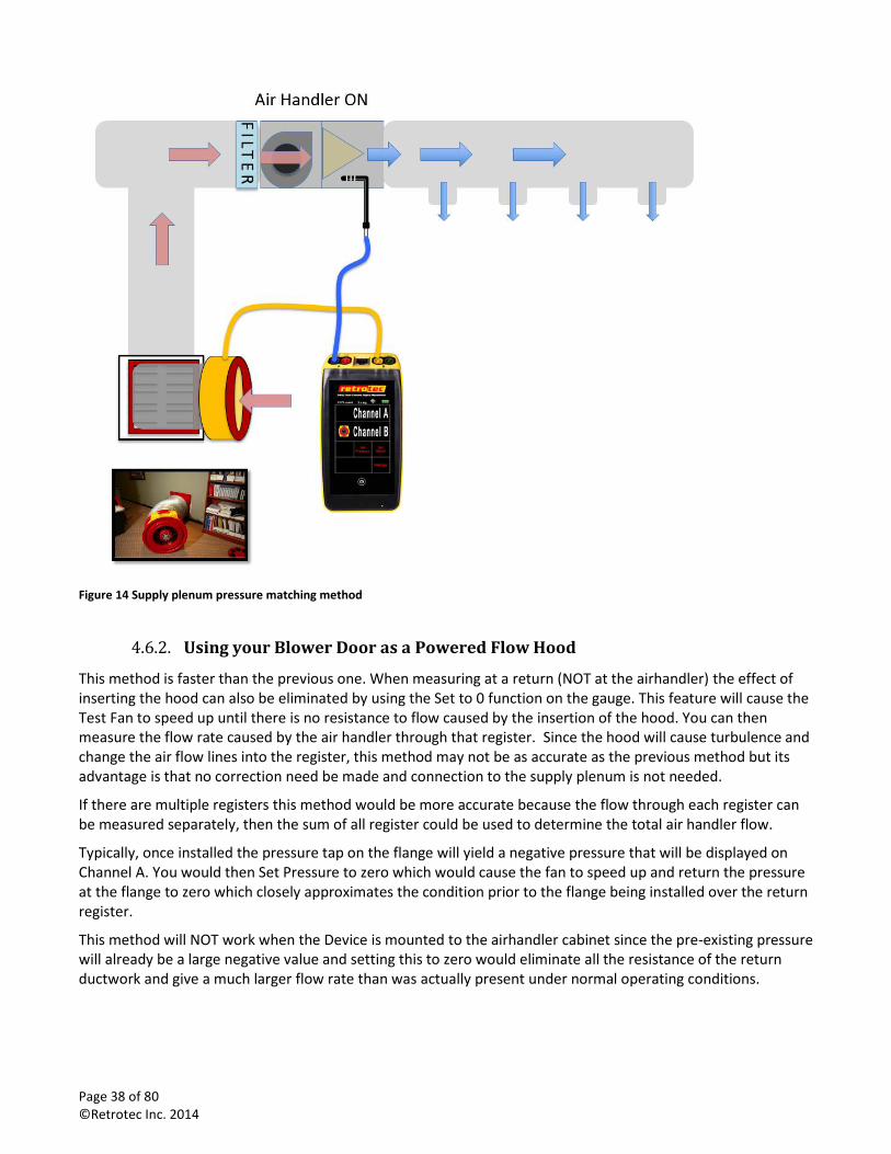
Page 38 of 80 ©Retrotec Inc. 2014
Figure 14 Supply plenum pressure matching method
4.6.2. Using your Blower Door as a Powered Flow Hood
This method is faster than the previous one. When measuring at a return (NOT at the airhandler) the effect of inserting the hood can also be eliminated by using the Set to 0 function on the gauge. This feature will cause the Test Fan to speed up until there is no resistance to flow caused by the insertion of the hood. You can then measure the flow rate caused by the air handler through that register. Since the hood will cause turbulence and change the air flow lines into the register, this method may not be as accurate as the previous method but its advantage is that no correction need be made and connection to the supply plenum is not needed.
If there are multiple registers this method would be more accurate because the flow through each register can be measured separately, then the sum of all register could be used to determine the total air handler flow.
Typically, once installed the pressure tap on the flange will yield a negative pressure that will be displayed on Channel A. You would then Set Pressure to zero which would cause the fan to speed up and return the pressure at the flange to zero which closely approximates the condition prior to the flange being installed over the return register.
This method will NOT work when the Device is mounted to the airhandler cabinet since the pre-existing pressure will already be a large negative value and setting this to zero would eliminate all the resistance of the return ductwork and give a much larger flow rate than was actually present under normal operating conditions.

Page 39 of 80
1. Connect the flex duct to the outlet of your Blower Door or Duct Tester (Test Fan).
2. Connect the other end of the flex to a return register using a Hood which could be a flange or box attached to the flex duct.
3. The yellow Fan Pressure tube must be connected between your test fan and gauge.
4. Connect the Blue tube between Channel A and the connection point on the Hood.
5. Run the airhandler at full speed with a clean filter in place.
6. Set gauge to 5 second averaging.
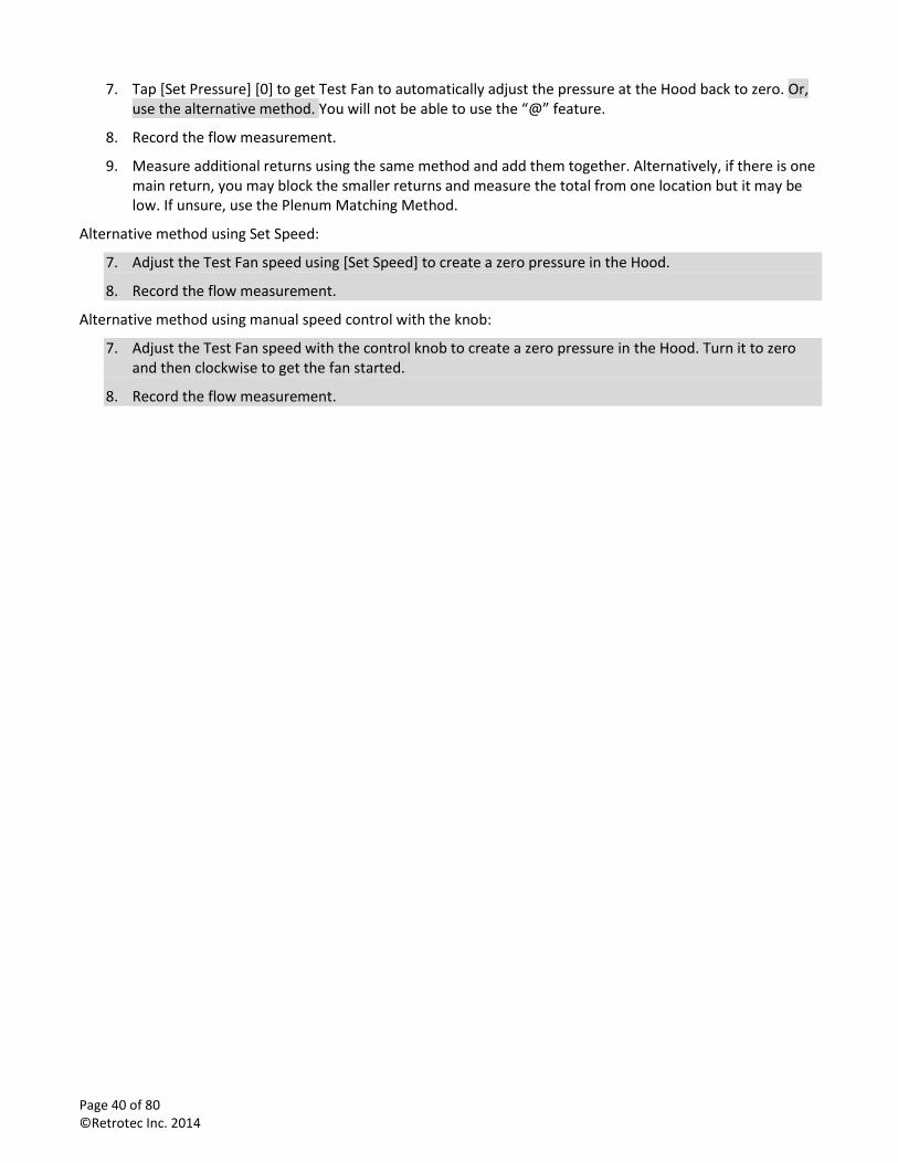
Page 40 of 80 ©Retrotec Inc. 2014
7. Tap [Set Pressure] [0] to get Test Fan to automatically adjust the pressure at the Hood back to zero. Or, use the alternative method. You will not be able to use the “@” feature.
8. Record the flow measurement.
9. Measure additional returns using the same method and add them together. Alternatively, if there is one main return, you may block the smaller returns and measure the total from one location but it may be low. If unsure, use the Plenum Matching Method.
Alternative method using Set Speed:
7. Adjust the Test Fan speed using [Set Speed] to create a zero pressure in the Hood.
8. Record the flow measurement.
Alternative method using manual speed control with the knob:
7. Adjust the Test Fan speed with the control knob to create a zero pressure in the Hood. Turn it to zero and then clockwise to get the fan started.
8. Record the flow measurement.

Page 41 of 80
4.7 Measure large exhaust and intake flow rates
The previous methods can be utilized to measure large rooftop exhaust or air intake flow rates. The essential idea behind the test method is to construct a tent over the source of the flow and to use a blower door to bring the pressure inside the measurement tent to zero and in so doing to not affect the flow rate that was there originally. There are two methods to do this:
1. Measure the pressure difference across the tent with at least two pressure hoses T’d together going to the Blue port of the gauge and to connect the red port of the gauge to at least two pressure hoses T’d together going to the Red port of the gauge. This works well in calm weather but when the wind is blowing it will be difficult to determine zero pressure.
2. Measure the pressure difference between inside the duct referenced to indoors. This pressure signal can be WiFi’ d to the operator on the roof who can measure the flow rate into or out of the tent required to re-establish the pressure in the duct prior to the installation of the tent.
Construction of the tent is from stock PRV pipe parts. They can be press fit together to create a framework and covered in plastic using Red Tuck Tape to hold 3 mil Poly together. The blower door fan may rest on the ground and be taped to the poly our mounted in a panel that is taped to the poly. Super tight fit is not essential because the tent will be very close to zero pressure during the measurements.
Use the “Set Pressure” function on the gauge to set the pressure to zero for method 1 and to the duct pressure in Method 2. Do NOT use the “@” function for Method 1 but you should use it for Method 2.
Rough guidelines for the minimum size of the tent are?
Tent size on each side Maximum flow into tent Maximum flow out of tent
2 feet 750 CFM 1500 CFM
3 feet 1500 CFM 3000 CFM
4 feet 3000 CFM 6000 CFM
6 feet 6000 CFM 12000 CFM
Larger tents generally work better because velocities are lower.
Figure 15 Tent made of poly and PVC pipe courtesy of Terry Brennan of Camroden Associates

Page 42 of 80 ©Retrotec Inc. 2014
5. Some Tests Require Pressure Gauge Only! Some pressure measurements can be done with a pressure gauge alone. These tests do not require a Blower Door be installed.
5.1 Combustion and Safety Tests
Combustion and safety tests are best done first, because serious system problems may prevent any further testing. Combustion Appliance Zone (CAZ) testing is an important aspect of house testing that can determine if there are any major safety problems. In some cases, air sealing activities done in conjunction with a Blower Door test can cause safety problems, as a tighter house is more likely to have depressurization problems (which can lead to combustion products and/or exhaust air leaking into the house).
Please note that the combustion and safety tests in this document are for general reference only. They should not take the place of local code requirements or procedures.
Combustion products can be spilled back into the building because of the following:
Poor or improper installation of HVAC equipment
Blocked or partially blocked chimneys, vents, or vent connectors
Damaged heat exchangers
Duct systems leaks
Cold temperatures in the chimney stack do not allow for much draft in the chimney flue
Depressurization in the Combustion Appliance Zone (air sealing can cause hazardous depressurization conditions from exhaust fans and forced air system imbalances)
5.1.1. CAZ Pressure Measurement
Vented combustion appliances require external venting of combustion by-products for safety reasons. If any appliances are vented, it is important to determine whether any of the exhaust can back draft (be pulled back into the house).
Worst Case Depressurization Test
There are a number of combustion tests that can be performed, however the most common, and simplest test is a Worst Case CAZ test. A Worst Case test looks to see if the combined force of all depressurization devices (exhaust fans) can create a negative pressure (relative to the outdoors), in an area containing a combustion appliance. If this situation exists, it's possible that the combustion products, including the very dangerous carbon monoxide, can be pulled into the house and not be vented outside.
To setup the house for a CAZ test
1. Seal the house by closing all exterior windows and doors 2. Open all interior doors 3. Open all supply and return registers 4. Turn off all combustion appliances
The following devices can create a negative pressure (with respect to the outdoors)
Bath exhaust fans
Range hoods
Clothes dryers

Page 43 of 80
Laundry room exhaust
Attic exhaust
HVAC air handler
Central vacuum with canister in unconditioned space
To conduct a Worst Case Depressurization Test
1. Connect the red pressure tube to the “Ref A” (red) port on the gauge, and run it outside. 2. Press [Baseline] to start taking a baseline reading. 3. Wait for 60 seconds. Press [Enter] to apply the baseline to the Channel A readings. 4. Turn on all of the exhaust devices. 5. Close interior doors that do not lead to rooms with an exhaust device. 6. Interior doors can have different effects on house pressure. Some experimentation may be required
when choosing to open or close an interior doorway. Monitor the interior pressure when interior doors are open. If the CAZ pressure becomes more negative, close the door, if not, the door can be left open.
7. A Blower Door can be used to simulate exhaust of 300 CFM for houses with fireplaces. Note: It is not safe to test with an actual fire burning.
8. Turn on the air handler. 9. If the pressure in the CAZ increases (becomes more positive), turn the air handler off. Interior door
positions may need to be changed with the air handler on. 10. Once the most negative possible pressure has been reached, record the value of “PrA” from the
gauge as the Worst Case Depressurization pressure.
Test each room with a combustion appliance. Depending on the appliances, there are safety standards that help determine the maximum safe depressurization limits. In general, a negative pressure in excess of -3 Pa would indicate a possible unsafe situation for atmospherically vented appliances. Induced draft appliances will not cause air quality problems until the negative pressure reaches -15 Pa. Discontinue testing if an excessive negative pressure develops. Potentially deadly buildups of Carbon Monoxide (CO) are possible if combustion appliances continue to run with a negative pressure in the house.
Table 7: BPI CAZ Pressure Limits
CAZ Depressurization Limits
Venting Condition Limit (Pa)
Orphan natural draft water heater (including outside chimneys) -2
Natural draft boiler or furnace commonly vented with water heater -3
Natural draft boiler or furnace with damper commonly vented with water heater -5
Individual natural draft boiler or furnace -5
Induced draft boiler or furnace commonly vented with water heater -5
Power vented or induced draft boiler or furnace alone, or fan assisted DHW alone -15
Chimney-top draft inducer; exhaust type or equivalent; high static pressure flame retention head oil burner; Direct vented appliances; Sealed combustion appliances
-50
5.1.2. Flue Draft Measurement
Measuring flue draft is another useful test to check the integrity of the venting system. Natural draft combustion appliances with a negative pressure inside the vent can begin back drafting combustion products back into the house.

Page 44 of 80 ©Retrotec Inc. 2014
To conduct a draft test
1. Drill a small hole in the vent pipe at the location identified in Figure 16. 2. Connect the red pressure tube to the “Ref A” (red) port on the gauge, and run it outside. 3. Connect the green pressure tube from the “Input B” (green) port on the gauge to the static pressure
probe (which is inserted into the drilled hole in the appliance vent). 4. The static pressure probe will cut down the effect of air flowing quickly past the tube, which can
have the same effect as wind on the pressure readings. 5. The “Ref B” (yellow) and “Input A” (blue) ports on the gauge must be open to the combustion room
pressure. 6. Press [Baseline] to start taking a baseline reading. 7. Wait for 60 seconds, or for the baseline measurement to be steady. Press [Enter] to apply the
baseline to the Channel A readings. 8. Turn the appliance ON, allow it to run for 5 minutes. 9. Set the gauge to measure pressure on Channel B (Mode “PrB”). 10. “PrA” is measuring the pressure from the outdoors to the CAZ, and “PrB” is measuring the draft
pressure.
Figure 16: Combustion appliance: Drill a small vent hole where indicated by the red star

Page 45 of 80
Operator inside of the CAZ Operator outside of the CAZ
Figure 17: Tubing set-up for CAZ tests with the operator inside and outside of the CAZ.
Ven
t
Combustion Appliance
Static Pressure Probe
Red hose to outside Hose to Vent
Blue/ yellow ports open
to CAZ
Ven
t
Combustion Appliance
Static Pressure Probe
Red hose to outside
Hose to Vent
Blue/ yellow hoses to CAZ

Page 46 of 80 ©Retrotec Inc. 2014
Figure 18: Example worst case flue draft test form
Worse case acceptable draft reading per outdoor temp

Page 47 of 80
5.2 Pressure Balancing and Performance Testing
5.2.1. Pressure Imbalances can be Due to Forced Air Systems
Air handlers typically move from 500 to 2000 CFM of air. When their supply and return flows are not in balance, the building itself can be subject to pressure imbalances. This can increase air infiltration rates, and cause susceptibility to radon and moisture entry, combustion appliance spillage, and backdrafting. A pressure imbalance of as low as 2 Pa can cause back drafting. It is important to understand how a home’s HVAC system contributes to the comfort and safety of the occupants.
Pressure imbalances can also be caused by duct leakage to the outdoors, and are exacerbated when the air handler/exhaust fans are on. If there are leaks in the supply duct, the building can suffer depressurization. Depressurization, even by 1 Pa, can lead to severe moisture problems in warm humid climates where infiltrating air carries high volumes of moisture. Infiltrating air will contact cooler surfaces (i.e. backside of gypsum board), reach the dew point and condense. Over time, this can create building integrity issues. When the leaks are in the return duct, the building will tend towards pressurization. When supply and return leaks are equivalent in size, the positive and negative pressures balance out. However this is not often the case.
The following is a set of diagnostic test procedures to help find pressure imbalances caused by leaks in the duct system. Note that these tests are sensitive to wind fluctuations so must be performed under calm conditions.
5.2.2. Run a Dominant Duct Leakage Test
This test will measure the depressurization or pressurization of the building caused by duct leakage to the outdoors while the air handler fan is running.
1. Close all exterior doors and windows, and open all interior doors. 2. Replace (cleaned) HVAC filters. Make sure the air handler and exhaust fans are off. 3. Connect the red tube to the “Ref A” (red) port on the gauge and send it outside. Keep the “Input A”
(blue) port open to the building. 4. Take a Baseline on the gauge to zero out any existing bias pressures in the building. 5. Record the air handler OFF pressure from “PrA” 6. Turn on the air handler fan (or exhaust fan) and record the air handler ON pressure 7. Calculate the pressure difference between ON and OFF readings.
Repeat this test several times for more accuracy in your results.
The results can indicate the following:
Consistent positive pressures indicate a leaky return duct system
Consistent negative results suggest a leaky supply duct system
The magnitude of the pressure reading will depend on the amount of imbalance and the tightness of the building being tested
No change in building pressure indicates that there is either equal supply and return leakage to the outside, no leaks to the outside, or the building is too leaky for the duct leakage to create a measurable pressure change
5.2.3. See if rooms with Closed Doors get pressurized by air handler running
The master bedroom is often the largest room in the home and can contain several supply registers, but no return registers. Measuring the effect of closing the bedroom door on the pressure in the main part of the house can determine whether or not the bedroom is becoming pressurized during air handler activity, while other parts of the home are being depressurized. This test can be repeated for other rooms in the building that have registers, and can be closed off from the main body of the house.

Page 48 of 80 ©Retrotec Inc. 2014
1. Connect the red tube to the “Ref A” (red) port and send the tube outside. The “Input A” (blue) port should remain open to the main body of the house.
2. To monitor the pressure in the room as well, connect the green tube to the “Input B” (green) port and put the other end of the tube under the bedroom door. Keep the “Ref B“ (yellow) port open to the main body of the house.
3. Turn on the air handler and close the bedroom door. Record the pressure changes that occur after closing the bedroom door. Channel A will show the pressure difference between the main body of the house and the outdoors, while Channel B will measure the pressure difference between the main body of the house and the bedroom.
4. If the pressure in the main body of the house changes by 1 Pa or more (in either direction), consider pressure relief measures.
5.2.4. See if the house or any room gets pressurized when all Interior Doors are
closed
Similar to the closed bedroom door test, this test looks at the pressure imbalances created when all interior doors are closed.
1. Set up the gauge to measure building pressure with respect to outside (red tube outside, blue port open). Take note of the pressure in the house with respect to outdoors.
2. Close all interior doors and turn on the air handler. Record the pressure change in the main body of the house. If the pressure changes by more than 2 Pa, consider pressure relief measures.
You can also measure the pressures induced by the air handler in each room by connecting the red tube to the gauge “Ref A”. Slide the end of the red tube under each door in turn to see the difference in pressure between the room and the main body of the house. Consider pressure relief measures if pressure differences exceed 3 Pa with respect to the main body.
This is often done for combustion appliance rooms to detect the potential for back drafting and spilling of combustion gases into the house.
5.2.5. Measure household exhaust fan flow
The Retrotec gauge can be used to measure the amount of air flowing through a hole. This feature enables the gauge to be used as an Exhaust Fan Flow Meter, by simply cutting a couple of holes in a cardboard box. The open end of the flow box should have rough dimensions which are at least two times the register dimensions, and the depth of the box should be at least the average of the other two dimensions.
To create an Exhaust Fan Flow Meter
1. Cut a hole in one side of a medium-sized cardboard box where it is only one layer thick, and leaving about one inch of cardboard around the edge for stiffness.
2. Cut a 2" x 2" square hole in the center of the other side of the box, again where the cardboard is only one layer thick. This is the flow measuring hole. For accuracy, the small hole should be at least 1.5 inches from the edge of the box and its area should be less than half the area of the end of the box.
3. Tape any cracks in the other sides of the box to prevent air from leaking. 4. Punch a 0.25 inch diameter hole near a corner of the open end of the box for the pressure tube.
Insert a tube in the hole. 5. Connect the tube to the “Ref B” (yellow) and "Input A" (blue) ports of the gauge using a T connector. 6. Fit the box over the exhaust fan grille while it is running, and seal in place around the box edges. 7. Observe the pressure in the box on “PrA”. The same pressure will show on “PrB” if “Mode” is set to
Pressure.
Figure 19: Exhaust fan flow meter

Page 49 of 80
8. Increase the size of the flow measuring hole in the box until the pressure is between 2 and 8 Pa. 9. Look up the Exhaust Flow in Table 7 based on the pressure in the box (from “PrA”) and the final area
of the flow measuring hole. 10. If you have a Retrotec gauge, it can calculate the exhaust fan flow for you.
a. Set the “Mode” to “Hole Flow”. b. Enter the area of the hole into the gauge using the [Area] key. c. Read the Exhaust Flow in CFM directly from the gauge on Channel B, “Hole Flow”.
Tip: Box pressure of 8 Pa or less is recommended because higher pressures will decrease the exhaust fan flow rate. Box pressures below 3 Pa are less accurate because small fluctuations in pressure will affect the flow a lot. Try the same fan with different holes to see the different results.
Table 8: Determine exhaust fan flow in CFM (grey cells) with a known hole size under known pressure conditions.
Exhaust Flow
(CFM)
Hole Size (sq in)
4 5 6 8 10 12 14 16 18 20 25 30 35 40 45 50 55 60 65 70
Pre
ssu
re (
Pa)
1 4 5 6 9 11 13 15 17 19 22 27 32 38 43 48 54 59 65 70 75
2 5 7 8 11 13 16 18 21 24 26 33 40 46 53 59 66 72 79 86 92
2 6 8 9 12 15 18 21 24 27 30 38 46 53 61 68 76 84 91 99 106
3 7 9 11 15 19 22 26 30 34 37 47 56 65 75 84 93 102 112 121 130
4 9 11 13 17 22 26 30 34 39 43 54 65 75 86 97 108 118 129 140 151
5 10 12 14 19 24 29 34 38 43 48 60 72 84 96 108 120 132 144 156 168
6 11 13 16 21 26 32 37 42 47 53 66 79 92 105 119 132 145 158 171 184
7 11 14 17 23 28 34 40 46 51 57 71 85 100 114 128 142 157 171 185 199
8 12 15 18 24 30 37 43 49 55 61 76 91 106 122 137 152 167 183 198 213
9 13 16 19 26 32 39 45 52 58 65 81 97 113 129 145 161 177 194 210 226
10 14 17 20 27 34 41 48 54 61 68 85 102 119 136 153 170 187 204 221 238
11 14 18 21 29 36 43 50 57 64 71 89 107 125 143 161 178 196 214 232 250
5.2.6. Use a pre-built Exhaust Fan Flow Meter instead of building your own box
There are pre-built meters available, which are just a box with a hole in it of a known size as described in the previous section on “Create an Exhaust Fan Flow Meter”. If you wish to use a manufactured box with a hole in it such as the “Exhaust Fan Flow Meter” built by The Energy Conservatory, you can measure the pressure in the flow meter box on any channel of the gauge and look up the flow in the manufacturer’s table reproduced in this document. You can also use the “Hole Flow” Mode on the Retrotec gauge to do the calculation and read the result directly from the gauge as described in the previous instructions.
The Retrotec DM32 and later models of the DM-2 works directly with the “Exhaust Fan Flow Meter”. Set your gauge’s Device to “Mn Exhaust Fan” on the DM-2 or change the Device to “Exhaust” on your DM32. Connect the Meter to Channel B and read off the flow directly. Make sure you are on the correct Range Configuration which should be E1, E2 or E3. You should also check the pressure inside the flow box to ensure it’s not above 10 Pa since this excessive pressure will reduce the fan’s flow rate. If greater than 10 Pa, change to a more open Configuration on the box.

Page 50 of 80 ©Retrotec Inc. 2014
Older models of DM-2 gauge may not give flow readings. Above 10 Pa, this Mode should work fine but the procedure outlined below will always work.
When the “Exhaust Fan Flow Meter” box itself is physically set to a Range of E1, enter an area of 40.7 square inches for the “Hole Flow” Mode on your DM-2 gauge because this is the size of the hole in that box and has been verified to give the same results as the table above. If you change hole size on the “Exhaust Fan Flow Meter”, change the area in the gauge to match:
1. E1 setting, Enter 40.7 square inches 2. E2 setting, Enter 19.3 square inches 3. E3 setting, Enter 9.4 square inches
Table 9: Manufactured Flow Meter Pressure-Flow Look-up
5.2.7. Measure air handler flow with a Flow Grid
Temporarily replacing the filter in the air handler distribution system with a grid containing holes of a known size while the air handler is running allows measurement of the airflow being produced by the air handler. If the

Page 51 of 80
filter location is directly adjacent to the air handler, the process will measure the total air handler flow. If the filter is located remotely at a central return, the process will measure airflow through the central return.
The Retrotec gauge can be used with the TrueFlow® Air Handler Flow Meter built by The Energy Conservatory to measure the system air flow using the reading from the Grid and the operating pressure.
Measure the Normal System Operating Pressure (NSOP)
1. Identify the air handler filter, and replace it if dirty. 2. Open all supply and return registers, and open a window or door between the building and the
outside. 3. Insert a static pressure probe into the duct system in any of the following locations:
A side of the supply plenum that does not have a trunk line, supply register, or distribution duct connected.
A corner of the plenum that does not have any connections within eight inches.
A side of the return plenum that does not have a trunk line, supply register, or distribution duct connected, and that is a minimum of 24 inches upstream of the TrueFlow® Meter and a minimum of 24 inches downstream of any 90 degree bends in the duct, or trunk line connections.
4. Connect a pressure tube from the static pressure probe to the “Input A” (blue) port on the gauge. If the gauge is not located inside of the house for this test, run a pressure tube from the “Ref A” (red) port to the inside of the house.
5. Turn the air handler on. 6. “PrA” is measuring the Normal System Operating Pressure in Pa. 7. Press [Time Avg] to select 1m (one minute) for a one minute averaging on the reading. 8. Wait two minutes before recording the Normal System Operating Pressure. 9. If the measured pressure is less than 10 Pa, or fluctuating significantly, try a different location for
the static pressure probe.
Measure the TrueFlow® System Operating Pressure (TFSOP) and Total Air Handler Flow
10. After measuring the Normal System Operating Pressure, turn the air handler off and remove the existing filter.
11. Assemble the metering plate, with the necessary spacers to match the filter slot (see Table 14). 12. Install the metering plate. The front of the plate should face into the airflow. Close the filter access
opening. If the plate is installed in a filter grille from a single return duct system, leave the grille door open.
13. Turn the air handler back on (to the same full blower speed setting used to measure the Normal System Operating Pressure).
14. Connect a tube from the red hose on the pressure grid to the Green “Input B” port on the gauge. 15. Connect a tube from the green hose on the pressure grid to the Yellow “Ref B” port on the gauge. 16. Choose the True Flow® as the Device on the gauge. 17. On DM-2, select the Range as either the #14 or #22 Plate.
a. #22 must be selected on the DM-2 for Plate #20 on the True Flow Grid. 18. On DM32, select the Range as either the #14 or #20 Plate. 19. Set the gauge to display Flow on Channel B.

Page 52 of 80 ©Retrotec Inc. 2014
20. Channel A now displays the TrueFlow® System Operating Pressure, and Channel B displays the Total Air Handler Flow. If flow is not displayed, temporarily disconnect the tube on Channel A and the flow will be displayed. Channel A pressure must be at least 10 Pa otherwise no flow reading will be displayed because 10 Pa is the minimum pressure signal; even then, at pressures below 25 Pa the Flow Grid will not be very accurate. Notice the table does not show flows for Channel B less than 10 Pa.
21. To calculate the Adjusted Total Air Handler Flow choose The easy way or The hard way below. Only Retrotec has the exclusive option to make this calculation the easy way.
Correct Total Air Handler Flow reading to what it would be if the standard filter was in place instead of the TrueFlow®
The flow reading on Channel B is the Total Air Handler Flow. In order to determine the actual flow, as it would be with a standard filter in place, the Adjusted Total Air Handler Flow needs to be calculated from the Normal System Operating Pressure (NSOP) and the TrueFlow® System Operating Pressure (TFSOP).
The easy way
With a Retrotec gauge, first set n to 0.5 using the Set Up key. Then measure the supply pressure in a stable location under normal conditions with a clean filter. Let’s say its 121 Pa. Set Pressure on the gauge to 121 Pa and Enter even though we aren’t going to use the gauge to control anything, this step makes the calculation that comes next, easy. With the Flow Grid installed and Gauge set to the Flow Grid, measure the flow at say 1000 CFM on Channel B with a pressure of 100 Pa on Channel A. To get the gauge to perform the correction, press the [@] key until the previous supply plenum pressure appears, such as “1100 CFM @121 Pa” for this example. The flow is now corrected without any further calculations.
To confirm this calculation is correct you can set NSOP to 121 and TFSOP to 100 in the below equation. Now, do it the easy way.
The hard way:
The Adjusted Total Air Handler Flow = √NSOP
TFSOP × 𝑇𝑜𝑡𝑎𝑙 𝐴𝑖𝑟 𝐻𝑎𝑛𝑑𝑙𝑒𝑟 𝐹𝑙𝑜𝑤
Eg: A total air handler flow of 1000 CFM is measured, the NSOP=75 Pa and the TFSOP =60Pa. Calculate 75/60= 1.25. Square root of 1.25 = 1.118 Multiply air handler flow of 1000 CFM by 1.118 to get an Adjusted Total Air Handler Flow of 1,118 CFM which represents the actual system air handler flow.
√NSOP
TFSOP can be calculated directly or read from Table 10.
Table 10: Square roots of Normal to TrueFlow® System Operating Pressure ratios.
𝑵𝑺𝑶𝑷
𝑻𝑭𝑺𝑶𝑷 √
𝑵𝑺𝑶𝑷
𝑻𝑭𝑺𝑶𝑷 𝑵𝑺𝑶𝑷
𝑻𝑭𝑺𝑶𝑷 √
𝑵𝑺𝑶𝑷
𝑻𝑭𝑺𝑶𝑷
1.40 1.183 1.05 1.025
1.39 1.179 1.04 1.020
1.38 1.175 1.03 1.015
1.37 1.170 1.02 1.010
1.36 1.166 1.01 1.005
1.35 1.162 1.00 1.000
1.34 1.158 0.99 0.995

Page 53 of 80
1.33 1.153 0.98 0.990
1.32 1.149 0.97 0.985
1.31 1.145 0.96 0.980
1.30 1.140 0.95 0.975
1.29 1.136 0.94 0.970
1.28 1.131 0.93 0.964
1.27 1.127 0.92 0.959
1.26 1.122 0.91 0.954
1.25 1.118 0.90 0.949
1.24 1.114 0.89 0.943
1.23 1.109 0.88 0.938
1.22 1.105 0.87 0.933
1.21 1.100 0.86 0.927
1.20 1.095 0.85 0.922
1.19 1.091 0.84 0.917
1.18 1.086 0.83 0.911
1.17 1.082 0.82 0.906
1.16 1.077 0.81 0.900
1.15 1.072 0.80 0.894
1.14 1.068 0.79 0.889
1.13 1.063 0.78 0.883
1.12 1.058 0.77 0.877
1.11 1.054 0.76 0.872
1.10 1.049 0.75 0.866
1.09 1.044 0.74 0.860
1.08 1.039 0.73 0.854
1.07 1.034 0.72 0.849
1.06 1.030 0.71 0.843
Determine Adjusted Total Air Handler Flow manually using gauge and look up tables
1. Connect the tubing from the installed metering plate to the yellow and green ports (“Ref B” and “Input B”) on the gauge.
2. Display Pressure on Channel B, “PrB” in Pascals (Pa) and record “PrB”. 3. Use Table 11 to determine the flow (in CFM) at the recorded pressure. 4. Use Table 12 to calculate adjusted airflow.
Table 11: Flow through TrueFlow® metering plates at various pressures
Pressure (Pa)
#14 (CFM)
#20 (CFM) Pressure
(Pa)
#14 (CFM)
#20 (CFM) Pressure
(Pa)
#14 (CFM)
#20 (CFM)
10 364 487 70 962 1288 130 1311 1756
11 381 511 71 969 1298 131 1316 1763
12 398 533 72 976 1307 132 1321 1769
13 415 555 73 983 1316 133 1326 1776
14 430 576 74 989 1325 134 1331 1783
15 445 596 75 996 1334 135 1336 1789
16 460 616 76 1003 1343 136 1341 1796
17 474 635 77 1009 1351 137 1346 1803
18 488 653 78 1016 1360 138 1351 1809
19 501 671 79 1022 1369 139 1356 1816
20 514 689 80 1029 1377 140 1361 1822
21 527 706 81 1035 1386 141 1366 1829
22 539 722 82 1041 1395 142 1370 1835
23 552 739 83 1048 1403 143 1375 1842
24 563 754 84 1054 1411 144 1380 1848
25 575 770 85 1060 1420 145 1385 1854
26 586 785 86 1066 1428 146 1390 1861
27 598 800 87 1073 1436 147 1394 1867
28 609 815 88 1079 1445 148 1399 1873
29 619 829 89 1085 1453 149 1404 1880
30 630 843 90 1091 1461 150 1408 1886
31 640 857 91 1097 1469 151 1413 1892
32 651 871 92 1103 1477 152 1418 1899

Page 54 of 80 ©Retrotec Inc. 2014
Pressure (Pa)
#14 (CFM)
#20 (CFM) Pressure
(Pa)
#14 (CFM)
#20 (CFM) Pressure
(Pa)
#14 (CFM)
#20 (CFM)
33 661 885 93 1109 1485 153 1422 1905
34 671 898 94 1115 1493 154 1427 1911
35 680 911 95 1121 1501 155 1432 1917
36 690 924 96 1127 1509 156 1436 1923
37 700 937 97 1133 1517 157 1441 1930
38 709 949 98 1138 1525 158 1446 1936
39 718 962 99 1144 1532 159 1450 1942
40 727 974 100 1150 1540 160 1455 1948
41 736 986 101 1156 1548 161 1459 1954
42 745 998 102 1161 1555 162 1464 1960
43 754 1010 103 1167 1563 163 1468 1966
44 763 1022 104 1173 1570 164 1473 1972
45 771 1033 105 1178 1578 165 1477 1978
46 780 1044 106 1184 1586 166 1482 1984
47 788 1056 107 1190 1593 167 1486 1990
48 797 1067 108 1195 1600 168 1491 1996
49 805 1078 109 1201 1608 169 1495 2002
50 813 1089 110 1206 1615 170 1499 2008
51 821 1100 111 1212 1622 171 1504 2014
52 829 1111 112 1217 1630 172 1508 2020
53 837 1121 113 1222 1637 173 1513 2026
54 845 1132 114 1228 1644 174 1517 2031
55 853 1142 115 1233 1651 175 1521 2037
56 861 1152 116 1239 1659 176 1526 2043
57 868 1163 117 1244 1666 177 1530 2049
58 876 1173 118 1249 1673 178 1534 2055
59 883 1183 119 1255 1680 179 1539 2060
60 891 1193 120 1260 1687 180 1543 2066
61 898 1203 121 1265 1694 181 1547 2072
62 906 1213 122 1270 1701 182 1551 2078
63 913 1222 123 1275 1708 183 1556 2083
64 920 1232 124 1281 1715 184 1560 2089
65 927 1242 125 1286 1722 185 1564 2095
66 934 1251 126 1291 1729 67 941 1261 127 1296 1735 68 948 1270 128 1301 1742 69 955 1279 129 1306 1749

Page 55 of 80
Table 12: Flow Resistance Correction Factors for TrueFlow® Grid Operation (10-50 Pa).
Tru
eFl
ow
® S
yste
m O
pe
rati
ng
Pre
ssu
re (
Pa)
Normal System Operating Pressure (Pa)
10 12 14 16 18 20 22 24 26 28 30 32 34 36 38 40 42 44 46 48 50
10 1 1.1 1.18 1.26 1.34 1.41 1.48 1.55 1.61 1.67 1.73 1.79 1.84 1.9 1.95 2 2.05 2.1 2.14 2.19 2.24
12 0.91 1 1.08 1.15 1.22 1.29 1.35 1.41 1.47 1.53 1.58 1.63 1.68 1.73 1.78 1.83 1.87 1.91 1.96 2 2.04
14 0.85 0.93 1 1.07 1.13 1.2 1.25 1.31 1.36 1.41 1.46 1.51 1.56 1.6 1.65 1.69 1.73 1.77 1.81 1.85 1.89
16 0.79 0.87 0.94 1 1.06 1.12 1.17 1.22 1.27 1.32 1.37 1.41 1.46 1.5 1.54 1.58 1.62 1.66 1.7 1.73 1.77
18 0.75 0.82 0.88 0.94 1 1.05 1.11 1.15 1.2 1.25 1.29 1.33 1.37 1.41 1.45 1.49 1.53 1.56 1.6 1.63 1.67
20 0.71 0.77 0.84 0.89 0.95 1 1.05 1.1 1.14 1.18 1.22 1.26 1.3 1.34 1.38 1.41 1.45 1.48 1.52 1.55 1.58
22 0.67 0.74 0.8 0.85 0.9 0.95 1 1.04 1.09 1.13 1.17 1.21 1.24 1.28 1.31 1.35 1.38 1.41 1.45 1.48 1.51
24 0.65 0.71 0.76 0.82 0.87 0.91 0.96 1 1.04 1.08 1.12 1.15 1.19 1.22 1.26 1.29 1.32 1.35 1.38 1.41 1.44
26 0.62 0.68 0.73 0.78 0.83 0.88 0.92 0.96 1 1.04 1.07 1.11 1.14 1.18 1.21 1.24 1.27 1.3 1.33 1.36 1.39
28 0.6 0.65 0.71 0.76 0.8 0.85 0.89 0.93 0.96 1 1.04 1.07 1.1 1.13 1.16 1.2 1.22 1.25 1.28 1.31 1.34
30 0.58 0.63 0.68 0.73 0.77 0.82 0.86 0.89 0.93 0.97 1 1.03 1.06 1.1 1.13 1.15 1.18 1.21 1.24 1.26 1.29
32 0.56 0.61 0.66 0.71 0.75 0.79 0.83 0.87 0.9 0.94 0.97 1 1.03 1.06 1.09 1.12 1.15 1.17 1.2 1.22 1.25
34 0.54 0.59 0.64 0.69 0.73 0.77 0.8 0.84 0.87 0.91 0.94 0.97 1 1.03 1.06 1.08 1.11 1.14 1.16 1.19 1.21
36 0.53 0.58 0.62 0.67 0.71 0.75 0.78 0.82 0.85 0.88 0.91 0.94 0.97 1 1.03 1.05 1.08 1.11 1.13 1.15 1.18
38 0.51 0.56 0.61 0.65 0.69 0.73 0.76 0.79 0.83 0.86 0.89 0.92 0.95 0.97 1 1.03 1.05 1.08 1.1 1.12 1.15
40 0.5 0.55 0.59 0.63 0.67 0.71 0.74 0.77 0.81 0.84 0.87 0.89 0.92 0.95 0.97 1 1.02 1.05 1.07 1.1 1.12
42 0.49 0.53 0.58 0.62 0.65 0.69 0.72 0.76 0.79 0.82 0.85 0.87 0.9 0.93 0.95 0.98 1 1.02 1.05 1.07 1.09
44 0.48 0.52 0.56 0.6 0.64 0.67 0.71 0.74 0.77 0.8 0.83 0.85 0.88 0.9 0.93 0.95 0.98 1 1.02 1.04 1.07
46 0.47 0.51 0.55 0.59 0.63 0.66 0.69 0.72 0.75 0.78 0.81 0.83 0.86 0.88 0.91 0.93 0.96 0.98 1 1.02 1.04
48 0.46 0.5 0.54 0.58 0.61 0.65 0.68 0.71 0.74 0.76 0.79 0.82 0.84 0.87 0.89 0.91 0.94 0.96 0.98 1 1.02
50 0.45 0.49 0.53 0.57 0.6 0.63 0.66 0.69 0.72 0.75 0.77 0.8 0.82 0.85 0.87 0.89 0.92 0.94 0.96 0.98 1

Page 56 of 80 ©Retrotec Inc. 2014
Table 13: Flow Resistance Correction Factors for TrueFlow® Operation (50-150 Pa).
Tru
eFl
ow
® S
yste
m O
pe
rati
ng
Pre
ssu
re (
Pa)
Normal System Operating Pressure (Pa)
50 55 60 65 70 75 80 85 90 95 100 105 110 115 120 125 130 135 140 145 150
50 1 1.05 1.1 1.14 1.18 1.22 1.26 1.3 1.34 1.38 1.41 1.45 1.48 1.52 1.55 1.58 1.61 1.64 1.67 1.7 1.73
55 0.95 1 1.04 1.09 1.13 1.17 1.21 1.24 1.28 1.31 1.35 1.38 1.41 1.45 1.48 1.51 1.54 1.57 1.6 1.62 1.65
60 0.91 0.96 1 1.04 1.08 1.12 1.15 1.19 1.22 1.26 1.29 1.32 1.35 1.38 1.41 1.44 1.47 1.5 1.53 1.55 1.58
65 0.88 0.92 0.96 1 1.04 1.07 1.11 1.14 1.18 1.21 1.24 1.27 1.3 1.33 1.36 1.39 1.41 1.44 1.47 1.49 1.52
70 0.85 0.89 0.93 0.96 1 1.04 1.07 1.1 1.13 1.16 1.2 1.22 1.25 1.28 1.31 1.34 1.36 1.39 1.41 1.44 1.46
75 0.82 0.86 0.89 0.93 0.97 1 1.03 1.06 1.1 1.13 1.15 1.18 1.21 1.24 1.26 1.29 1.32 1.34 1.37 1.39 1.41
80 0.79 0.83 0.87 0.9 0.94 0.97 1 1.03 1.06 1.09 1.12 1.15 1.17 1.2 1.22 1.25 1.27 1.3 1.32 1.35 1.37
85 0.77 0.8 0.84 0.87 0.91 0.94 0.97 1 1.03 1.06 1.08 1.11 1.14 1.16 1.19 1.21 1.24 1.26 1.28 1.31 1.33
90 0.75 0.78 0.82 0.85 0.88 0.91 0.94 0.97 1 1.03 1.05 1.08 1.11 1.13 1.15 1.18 1.2 1.22 1.25 1.27 1.29
95 0.73 0.76 0.79 0.83 0.86 0.89 0.92 0.95 0.97 1 1.03 1.05 1.08 1.1 1.12 1.15 1.17 1.19 1.21 1.24 1.26
100 0.71 0.74 0.77 0.81 0.84 0.87 0.89 0.92 0.95 0.97 1 1.02 1.05 1.07 1.1 1.12 1.14 1.16 1.18 1.2 1.22
105 0.69 0.72 0.76 0.79 0.82 0.85 0.87 0.9 0.93 0.95 0.98 1 1.02 1.05 1.07 1.09 1.11 1.13 1.15 1.18 1.2
110 0.67 0.71 0.74 0.77 0.8 0.83 0.85 0.88 0.9 0.93 0.95 0.98 1 1.02 1.04 1.07 1.09 1.11 1.13 1.15 1.17
115 0.66 0.69 0.72 0.75 0.78 0.81 0.83 0.86 0.88 0.91 0.93 0.96 0.98 1 1.02 1.04 1.06 1.08 1.1 1.12 1.14
120 0.65 0.68 0.71 0.74 0.76 0.79 0.82 0.84 0.87 0.89 0.91 0.94 0.96 0.98 1 1.02 1.04 1.06 1.08 1.1 1.12
125 0.63 0.66 0.69 0.72 0.75 0.77 0.8 0.82 0.85 0.87 0.89 0.92 0.94 0.96 0.98 1 1.02 1.04 1.06 1.08 1.1
130 0.62 0.65 0.68 0.71 0.73 0.76 0.78 0.81 0.83 0.85 0.88 0.9 0.92 0.94 0.96 0.98 1 1.02 1.04 1.06 1.07
135 0.61 0.64 0.67 0.69 0.72 0.75 0.77 0.79 0.82 0.84 0.86 0.88 0.9 0.92 0.94 0.96 0.98 1 1.02 1.04 1.05
140 0.6 0.63 0.65 0.68 0.71 0.73 0.76 0.78 0.8 0.82 0.85 0.87 0.89 0.91 0.93 0.94 0.96 0.98 1 1.02 1.04
145 0.59 0.62 0.64 0.67 0.69 0.72 0.74 0.77 0.79 0.81 0.83 0.85 0.87 0.89 0.91 0.93 0.95 0.96 0.98 1 1.02
150 0.58 0.61 0.63 0.66 0.68 0.71 0.73 0.75 0.77 0.8 0.82 0.84 0.86 0.88 0.89 0.91 0.93 0.95 0.97 0.98 1

Page 57 of 80
Installing spacers for the metering plate
The accuracy of the metering plate is reduced if there are obstructions with six inches upstream, or two inches downstream of the plate, or if there is a 90 degree bend in the duct directly downstream. The spacers (if attached) can be used to lessen the impact of any obstructions. Simply place the spacers against the obstructions, if possible, or install the spacer so that it is on the inside corner of the bend.
Table 14: TrueFlow® Metering Plate spacer selection depending on filter size
Filter Size Plate # Spacer 1 Spacer 2
14x20 #14– select 14 on the DM2 - -
14x25 #14 “ 5x14 -
16x20 #14 “ 2x20 -
16x24 #14 “ 2x20 4x16
16x25 #14 “ 2x20 5x16
18x20 #14 “ 4x20 -
20x20 #20 – select 22 on the DM2 - -
20x22 #20 “ 2x20 -
20x24 #20 “ 4x20 -
20x25 #20 “ 5x20 -
20x30 #20 “ 10x20 -
24x24 #20 “ 4x20 4x24

Page 58 of 80 ©Retrotec Inc. 2014
Appendix A: Air Tightness Requirements Tables Many of the air tightness requirements depend on the climate zone. Climate zone information can be found at the US Department of Energy Climate Zones page.

Page 59 of 80
Residential Air Tightness Requirements
Table 15: Residential airtightness requirements based on floor area of 2,250 sq ft, height of 8 ft, n=0.65.

Page 60 of 80 ©Retrotec Inc. 2014

Page 61 of 80

Page 62 of 80 ©Retrotec Inc. 2014
Large Building Air Tightness Requirements
Table 16: Commercial airtightness requirements based on a 4 storey building, 120 x 110 x 8 ft per storey, n=0.65
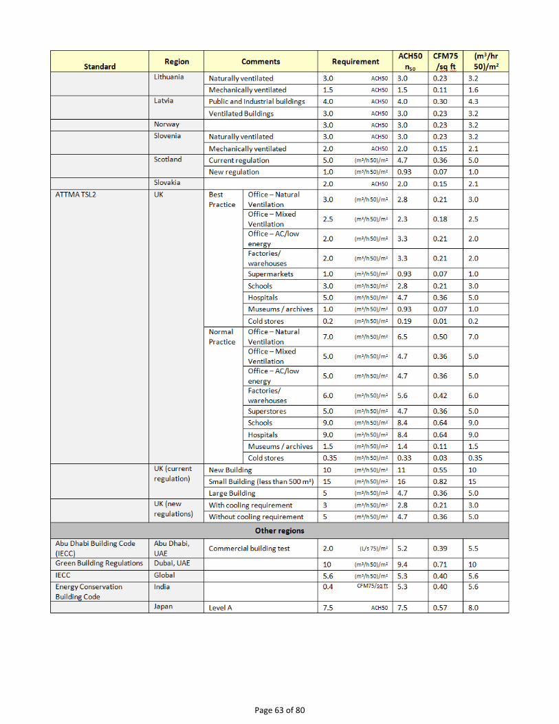
Page 63 of 80

Page 64 of 80 ©Retrotec Inc. 2014
Air Tightness Requirements for Assemblies
Table 17: Air tightness requirements for Assemblies
Standard Region Comments Requirement ACH50
n50 CFM75
/sq ft (m3/hr)50
/m2
North America
Canadian NBC for RH Canada 0.1 (L/s 50)/m2 0.26 0.02 0.28
National Canadian Building Code
Canada Assemblies 0.15 (L/s 50)/m2 0.33 0.025 0.35
Comparison of different Air Leakage Results for the same enclosure
Table 18: Comparison of different units for a house 50 x 30 x 20 feet, with n=0.65; proposed units are highlighted
Result Units Application
1,191 CFM50 House leakage in the US
1,550 CFM75 Large building leakage in the US
0.397 CFM50/sq ft House and duct leakage in the US
0.253 CFM50/sq ft House and duct leakage in the US, MLR
0.192 CFM50/sq ft House and duct leakage in the US
0.250 CFM75/sq ft Large building leakage in the US
0.249 (CFM @ 0.3 in WC)/sq ft Large building leakage in the US
66 sq in EfLA4 House leakage in the US
1.06 sq in EfLA4/100 sq ft Environmental Tobacco Smoke - apartment leakage in the US
123 sq in EqLA10 House leakage in Canada and US
157 sq in EqLA50
1.98 sq in EqLA10/100 sq ft
2.53 sq in EqLA50/100 sq ft
2.38 ACH50, n50 Proposed for houses and large buildings worldwide
0.000107 SLA, sq in EfLA50/ sq in House leakage in WA state must be 0.00030 or less
107 EfLA50/106 sq in
175 EqLA50/106 sq in (surface area) Proposed for all buildings
0.56 Q50, m3/s Large building leakage in Europe
196 V4 , m3/h All building leakage in France
2,023 V50 , m3/h Large building leakage in Europe

Page 65 of 80
Result Units Application
3.5115 Permeability, (m3/h)/m2 Large building leakage in the UK
4.63 Air Leakage index, (m3/h)/m2 Large building leakage in the UK
562 Q50, L/s House leakage in Canada and Europe
731 Q75, L/s Large building leakage in Canada and Europe
0.98 (L/s 50)/m2 Large building leakage in Canada and Europe @ 50 Pa
1.27 (L/s 75)/m2 Large building leakage in Canada and Europe @ 75 Pa
428 cm2 EfLA4
0.74 cm2 EfLA4/ m2
794 cm2 EqLA10 House leakage in Canada
1,010 cm2 EqLA50 House leakage in Canada and Europe
1.38 NLA, cm2 EqLA10/m2 House leakage in Canada
1.75 cm2 EqLA50/m2 Large building leakage in Canada and Europe
1.35 (cm2 [email protected])/m2 House leakage per unit floor are in Japan at 9.8 Pa
Table 19: Description of units used in requirements for air leakage
Acronym Requirement units Description
ACH50, n50 /h Air Changes per Hour, at 50 Pa induced pressure
CFM50/sq ft Cubic feet per minute, at 50 Pa induced pressure, per square foot of total enclosure
surface area
CFM75/sq ft Cubic Feet per Minute, at 75 Pa per square foot of total enclosure surface area
cm2 EqLA50/m2 Square centimeters of Equivalent Leakage Area, at 50 Pa induced pressure, per square
metre of enclosure surface area
EfLA50/106 Surface area Effective Leakage Area, at 50 Pa induced pressure, per million units of envelope area
EqLA50/106 Surface area Equivalent Leakage Area, at 50 Pa induced pressure, per million units of envelope area
(L/s)/m2 Litres per second per square metre of enclosure surface area
(L/s 50)/m2 Litres per second per square metre of enclosure surface area, at 50 Pa induced pressure
(m3/h)/m2 Permeability or air leakage index usually taken at 50 Pa induced pressure
(m3/h 50)/m2 Cubic metres per hour, at an induced pressure of 50 Pa, per square metre of total
enclosure area to outdoors including the ground. Usually under pressurization only although most Standards recommend testing both ways.
NLA sq in/sq ft Square inches of EqLA referenced to 10Pa per square foot of floor area.
Q50 L/s Volumetric air flow rate, in litres per second at 50 Pa induced pressure
ELA sq in EfLA4 Square inches of Effective Leakage Area at a reference pressure of 4 Pa extrapolated
from multiple test points taken between 15 and 60 Pa under depressurization.
sq in EfLA4/100 sq ft Square inches of Effective Leakage Area at 4 Pa per 100 square feet of enclosure surface
area extrapolated from multiple test points taken between 15 and 60 Pa under depressurization
V4 m3/h Volumetric air flow rate, in cubic meters per hour at 4 Pa induced pressure

Page 66 of 80 ©Retrotec Inc. 2014
Table 20: Resulting natural ventilation and potential savings in energy for various ACH50 values
ACH50
Natural Air
Change Rating
% of Energy
bill
% savings potential
Ventilation requirements
1.5 0.075 Super 2% none Requires constant energy recovery ventilation
3.5 0.18 Excellent 6% 1 to 3% Will require occasional forced ventilation
5 0.25 Better 10% 2 to 4% May require occasional forced ventilation
7 0.35 Good 14% 2 to 5% Does not require additional ventilation
10 0.50 Fair 20% 3 to 10% Start of excessive energy loss and over -ventilation
20 1.0 Bad 40% 5 to 20% Excessive energy loss and over –ventilation.
With reference to the Table 20 above:
ACH50 is the air flow at 50 Pa in CFM divided by the conditioned volume of the house.
Natural Air Change is the number of times per hour that all the air in the house will be changed, based on the value for ACH50. It is generally considered that 0.35 is sufficient but the amount is dependent upon occupancy, building dimensions, indoor pollution sources, and weather. Most homes will be under and over ventilated at different times.
% of energy bill is the amount of the total energy bill that can be attributed to air leakage.
% savings potential is attributed to the fact that leakage can be reduced by 12 to 50 % with the average being 25%. Duct leakages can double these losses.

Page 67 of 80
Appendix B: Calculate flow if required test pressure cannot be reached
“n” setting for estimating flow @ pressure during house and duct leakage test
Houses and ducts have leaks through holes that will have both turbulent and laminar flow going through them. The relationship between pressure and flow is as follows:
𝑓𝑙𝑜𝑤 = 𝑃𝑟𝑒𝑠𝑠𝑢𝑟𝑒𝑛 × 𝐶
The actual flow exponent n for an enclosure can be calculated by measuring enclosure leakage at multiple pressure differences, from 10 to 50 Pa, and determining the slope of the line when graphing log of flow versus log of pressure. The graph of pressure versus flow will be linear if graphed on a log-log scale, and the slope will be n. The constant C is a value depending on the flow characteristics of the opening through which the air is moving, and can be thought of as the flow at 1 Pa. Once n is known, flow at 1 Pa can be found using the graph.
A wide open hole has an n of 0.5, meaning that when the pressure is quadrupled, the flow doubles. That is due to completely turbulent flow going through that hole (flow = square root of pressure, a constant for that particular hole).
𝑓𝑙𝑜𝑤 = 𝑃𝑟𝑒𝑠𝑠𝑢𝑟𝑒𝑛
𝑓𝑙𝑜𝑤 = 𝑃𝑟𝑒𝑠𝑠𝑢𝑟𝑒0.5
An n value of 1.0 represents tiny little holes, so small that the air would not be turbulent but rather would go through the holes as laminar flow. This means that when pressure is quadrupled, the flow will also be quadrupled.
𝑓𝑙𝑜𝑤 = 𝑃𝑟𝑒𝑠𝑠𝑢𝑟𝑒1
𝑓𝑙𝑜𝑤 = 𝑃𝑟𝑒𝑠𝑠𝑢𝑟𝑒
4 ∗ 𝑓𝑙𝑜𝑤 = 4 ∗ 𝑃𝑟𝑒𝑠𝑠𝑢𝑟𝑒
Duct holes tend to be slightly larger so tend towards more laminar with less turbulent flow and larger n values, whereas houses have more prevalent long tiny cracks, and therefore tend to have lower n values.
The n value is saved in the gauge. Set it to 0.65 for houses, and 0.60 for ductwork. Set to 0.5 for tests on the Retrotec house simulator, while measuring air handler flow and for any large hole that is not composed of long thin cracks.
The gauge uses the n value to extrapolate for flows at other pressures using the following formula:
𝐹𝑙𝑜𝑤 𝑎𝑡 𝑑𝑒𝑠𝑖𝑟𝑒𝑑 𝑡𝑒𝑠𝑡 𝑝𝑟𝑒𝑠𝑠𝑢𝑟𝑒 = (𝐹𝑙𝑜𝑤 𝑎𝑡 𝑚𝑒𝑎𝑠𝑢𝑟𝑒𝑑 𝑝𝑟𝑒𝑠𝑠𝑢𝑟𝑒) ∗ (𝑑𝑒𝑠𝑖𝑟𝑒𝑑 𝑡𝑒𝑠𝑡 𝑝𝑟𝑒𝑠𝑠𝑢𝑟𝑒
𝑚𝑒𝑎𝑠𝑢𝑟𝑒𝑑 𝑝𝑟𝑒𝑠𝑠𝑢𝑟𝑒)
𝑛
Note that because the formula is using a ratio of the two pressures, and both pressures will have the same C, the C value is not required for the extrapolation.
For example: If we guess at the n value of a duct as being 0.6 and measure 100 CFM at 20 Pa (by accident or by design), then the gauge will complete the following calculation to estimate the flow at 25 Pa:
𝑓𝑙𝑜𝑤@25 𝑃𝑎 = 𝑓𝑙𝑜𝑤@20 𝑃𝑎 ×250.6
200.6
If the test pressure (20 in this case) is close to the desired reference pressure (25 Pa in this case), then the correction is small and the value of n does not play as large a role. However, if the test pressure is much higher or lower than the reference pressure, the error can be greater.

Page 68 of 80 ©Retrotec Inc. 2014
The @ Pressure extrapolation feature is very useful for ensuring that results taken for flow reflect the flow at the desired test pressure, even when the pressure was not adjusted perfectly and was within 5 to 10 Pa of the desired test pressure.
Extrapolation Error for Flow if gauge “n” doesn’t match actual “n”
To continue the above example: The flow at 20 Pa is 100 CFM. Assume the actual n is 0.7, but this is unknown. Instead, 0.6 will be used.
The gauge would calculate:
𝐹𝑙𝑜𝑤@25 𝑃𝑎 = 25𝑛 × 𝐶𝐹𝑀
20𝑛
𝐹𝑙𝑜𝑤@25 𝑃𝑎 = 250.6 × 100
200.6
𝐹𝑙𝑜𝑤@25 𝑃𝑎 = 114 𝐶𝐹𝑀
However, if actual n was 0.7, the flow at 25 should have been:
𝐹𝑙𝑜𝑤@25 𝑃𝑎 = 250.7 × 100
200.7
𝐹𝑙𝑜𝑤@25 𝑃𝑎 = 117 𝐶𝐹𝑀
This value is less than 3% off from what it should be. If the test pressure was within 1 or 2 Pa of the reference pressure of 25 Pa, the @ Pressure reading would be exact.
If a gauge has the extrapolation or flow exponent “n” set to an assumed value but the actual exponent (the true exponent value that describes the enclosure) differs, the flow values estimated by the gauge when extrapolating will be off by a small error amount. The tables below show the percent error that can result from entering an incorrect exponent value in the gauge and using the [@ Pressure] function.
If the “n” value on the gauge is set to 0.65 and the actual enclosure n is different, a small error, as shown in Table 21 will result if the [@ Pressure] function is used at the Achieved Pressure to estimate a result at 50 Pa.
Table 21: Errors in Estimated Flow at 50 Pa if gauge "n"= 0.65 differs from actual n
Actual Flow Exponent (n) of Enclosure
0.50 0.55 0.60 0.65 0.70 0.75
Achieved Pressure (Pa)
10 -21.4% -14.9% -7.7% 0.0% 8.4% 17.5%
15 -16.5% -11.3% -5.8% 0.0% 6.2% 12.8%
20 -12.8% -8.8% -4.5% 0.0% 4.7% 9.6%
25 -9.9% -6.7% -3.4% 0.0% 3.5% 7.2%
30 -7.4% -5.0% -2.5% 0.0% 2.6% 5.2%
35 -5.2% -3.5% -1.8% 0.0% 1.8% 3.6%
40 -3.3% -2.2% -1.1% 0.0% 1.1% 2.3%
45 -1.6% -1.0% -0.5% 0.0% 0.5% 1.1%
50 0.0% 0.0% 0.0% 0.0% 0.0% 0.0%
55 1.4% 1.0% 0.5% 0.0% -0.5% -0.9%
60 2.8% 1.8% 0.9% 0.0% -0.9% -1.8%
65 4.0% 2.7% 1.3% 0.0% -1.3% -2.6%
70 5.2% 3.4% 1.7% 0.0% -1.7% -3.3%

Page 69 of 80
If the “n” value on the gauge is set to 0.60 and the building n is different, a small error, as shown in Table 22 will result if the [@ Pressure] function is used at the Achieved Pressure to estimate a result at 50 Pa.
Table 22: Errors in Estimated Flow at 50 Pa if gauge "n" = 0.60 differs from actual n
Actual Flow Exponent (n) of Enclosure
0.50 0.55 0.60 0.65 0.70 0.75
Achieved Pressure (Pa)
10 -14.9% -7.7% 0.0% 8.4% 17.5% 27.3%
15 -11.3% -5.8% 0.0% 6.2% 12.8% 19.8%
20 -8.8% -4.5% 0.0% 4.7% 9.6% 14.7%
25 -6.7% -3.4% 0.0% 3.5% 7.2% 11.0%
30 -5.0% -2.5% 0.0% 2.6% 5.2% 8.0%
35 -3.5% -1.8% 0.0% 1.8% 3.6% 5.5%
40 -2.2% -1.1% 0.0% 1.1% 2.3% 3.4%
45 -1.0% -0.5% 0.0% 0.5% 1.1% 1.6%
50 0.0% 0.0% 0.0% 0.0% 0.0% 0.0%
55 1.0% 0.5% 0.0% -0.5% -0.9% -1.4%
60 1.8% 0.9% 0.0% -0.9% -1.8% -2.7%
65 2.7% 1.3% 0.0% -1.3% -2.6% -3.9%
70 3.4% 1.7% 0.0% -1.7% -3.3% -4.9%
Achieved pressure is the actual maximum pressure achieved in the enclosure during the test.
Error = (Pressure of Interest
Achieved Pressure)
(Actual n−Assumed n)
In the tables, the Pressure of Interest is 50Pa, and Assumed n is 0.65 or 0.60
The actual flow exponent n for an enclosure can be calculated by measuring enclosure leakage at multiple pressure differences, from 10 to 50 Pa, and determining the slope of the line on the graph of pressure versus flow which will be linear if graphed on a log-log scale, and the slope will be n.
Cannot Reach 50 Pa Factors for houses
If you have a situation where you cannot reach the required 50 Pa during the test, there is a way to estimate the flow at that pressure based on the measured pressure and flow you did achieve. This is the procedure the gauge uses for extrapolating the flow at the required pressure when you use the [@ Pressure] key. The following equation describes the relationship between the flow at the required pressure of 50 Pa and the actual measured flow at the measured pressure:
Flow at 50 Pa = (Flow at measured pressure) ∗ (50 Pa
measured pressure)
n

Page 70 of 80 ©Retrotec Inc. 2014
CFM50 = CFMP ∗ (50
P)
n
Typically for ducts, the n value is 0.60, and for houses the n value is 0.65. For the flow at 25 Pa, replace “50” with “25.”
Rather than using the equation in the situation where the 50 Pa test pressure cannot be achieved, you can use tables with the factors already calculated and the following procedure. Take a flow (CFM) reading at the pressure achieved and multiply by the "Cannot reach 50 Pa factor” from Table 23 to get an estimate of the flow that would result at 50 Pa.
For example, if you read 1000 CFM at a building pressure of 30 Pa, the "Cannot reach 50 factor" from Table 23 is 1.39. To get the estimated flow at 50 Pa, make the following calculation:
1000 CFM × 1.39 = 1390 CFM
Thus the estimated result for CFM at 50 Pa will be 1390 CFM.
The factors depend on the “n” value chosen, and Table 23 is for “n” of 0.65 which is typical for houses.
Table 23: Factors for when a building pressure of 50 Pa cannot be reached (“n” value of 0.65)
Pressure achieved
Cannot reach 50 factor
Pressure achieved
Cannot reach 50 factor
50 1.00 25 1.57
49 1.01 24 1.61
48 1.03 23 1.66
47 1.04 22 1.71
46 1.06 21 1.76
45 1.07 20 1.81
44 1.09 19 1.88
43 1.10 18 1.94
42 1.12 17 2.02
41 1.14 16 2.10
40 1.16 15 2.19
39 1.18 14 2.29
38 1.20 13 2.40
37 1.22 12 2.53
36 1.24 11 2.68
35 1.26 10 2.85
34 1.28 9 3.05
33 1.31 8 3.29
32 1.34 7 3.59
31 1.36 6 3.97
30 1.39 5 4.47
29 1.42
28 1.46

Page 71 of 80
27 1.49
26 1.53
Cannot Reach 25 Pa Factors for ducts
Rather than using the equation in the situation where the 25 Pa test pressure cannot be achieved, you can use tables with the factors already calculated and the following procedure. Take a flow (CFM) reading at the pressure achieved and multiply by the "Cannot reach 25 Pa factor” from Table 24 to get an estimate of the flow that would result at 25 Pa.
For example, if you read 600 CFM at a building pressure of 19 Pa, the "Cannot reach 25 factor" from Table 24 is 1.18. To get the estimated flow at 25 Pa, make the following calculation:
600 CFM × 1.18 = 708 CFM
Thus the estimated result for CFM at 25 Pa will be 708 CFM.
The factors depend on the “n” value chosen, and Table 24 is for “n” of 0.60 which is typical for ducts.
Table 24: Factors for when a building pressure of 25 Pa cannot be reached (“n” value of 0.6).
Pressure achieved
Cannot reach 25 factor
25 1.00
24 1.02
23 1.05
22 1.08
21 1.11
20 1.14
19 1.18
18 1.22
17 1.26
16 1.31
15 1.36
14 1.42
13 1.48
12 1.55
11 1.64
10 1.73
9 1.85
8 1.98
7 2.15
6 2.35
5 2.63

Page 72 of 80 ©Retrotec Inc. 2014
Appendix C: Test Forms The following four sheets act as a complete test form for a residential air leakage test under the ASTM protocol. This form should accompany the tester to the testing location, where he/she will fill in the necessary information and perform a manual or automatic (with software) test-fan test on the building. This information can then be used to create a report for the client, or be entered into FanTestic software, which will produce a report automatically.
To use these forms:
1. Select and copy the following four (4) pages. 2. Paste the copied pages into a new Word document. 3. Print the document (or take it to the site electronically).

Page 73 of 80
Test and Building Information:
Test Technician: Fan: S/N: Gauge: S/N:
Building Description and Information: Contact Name:
Contact Phone:
Building Address:
Date: Time:
Pre-Test Checklist:
Before After Task Notes
House envelope preparation
Select most appropriate doorway to install the Blower Door system
Close all exterior doors (except test doorway)
Door to basement, open if conditioned, close if not
Close all windows, storms, and skylights
Close all attic accesses inside the house
Close any fireplace dampers, open dampers afterwards
Inside house preparation
Move any loose items in the direct path of the fan airflow
Open any interior doors to conditioned spaces
Turn off all ceiling fans
Check for any open flames or hot embers (if found, immediately discontinue test), cover cold ashes
Open to the outside (buffer zones)
Attic
Basement if unconditioned
Garage
Crawl space
Exhaust appliances: turn off
Kitchen & bath exhaust fans
Whole house fan
Clothes dryer
Central vacuum system
Other Devices:
Evaporative coolers - turn off
Window a/c units - turn off
Close outdoor air vents
Central heating & cooling system, Gas water heater:
Turn off
Building Air Leakage Test Form – ASTM E779-10

Page 74 of 80 ©Retrotec Inc. 2014
Open supply diffusers
Close damper over fresh/make-up air intake
Turn off fresh air ventilation system
Turn to pilot position, and leave keys on heater (so you remember to turn it back on)
ASTM Air Leakage Testing Procedure:
Make general observations (condition of windows, doors, walls, roof, floor, etc) and record enclosure measurements (area, volume, height). Sketch plan view of building to aid in calculating area and volume measurements.
Record information from the following steps in the appropriate sections on sheet 3 of this document.
Measure and record indoor and outdoor air temperatures before and after the test.(If the product between the difference in indoor/outdoor temperature multiplied by the building height is greater than 1180˚F, do not proceed with the test because stack pressure is too high to allow for accurate interpretation of results)
Set up the fan in your selected doorway Extend pressure tubing (red) through the door panel to the outdoors (if possible, use more than one location for pressure measurement (see ASTM standard). Buildings higher than 25ft should measure exterior pressure at more than one height and average the pressure pickups using a manifold.
Seal the fan before taking bias pressure (zero Fan Pressure measurements) readings Use the C range plate plugs or a nylon fan cover to cover the fan.
Take a (1) bias pressure reading averaged over at least 10s before the test begins (if it is windy, or there are high bias pressures, increase the averaging period of this bias pressure reading).
Induce pressures between 10 and 60 Pa, with increments between 5 and 10 Pa; measure building pressure and air flow rate over a 20s period. Use the “Set Pressure” feature on the gauge to induce pressures between 10 and 60 Pa (example, for 15Pa push: [Set Pressure] [1] [5] [Enter]) Record “PrA” values in the “Building gauge pressure” line Record “PrB” values in the “Blower Door pressure” line Record the flow range on the fan through which the pressures are being induced
Take a bias pressure reading averaged over at least 10s after the test ends (if it is windy, or there are high bias pressures, increase the averaging period of this bias pressure reading).
Repeat steps 4 to 9 in the opposite direction (i.e. perform both a pressurization AND depressurization set)
Elevation above sea level:
ft
Height above ground: ft
Enclosure Volume: cu ft
Floor Area: sq ft
Enclosure Area: sqft
Building Air Leakage Test Form – ASTM E779-10

Page 75 of 80
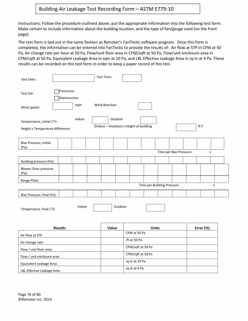
Page 76 of 80 ©Retrotec Inc. 2014
Instructions: Follow the procedure outlined above; put the appropriate information into the following test form. Make certain to include information about the building location, and the type of fan/gauge used (on the front page).
The test form is laid out in the same fashion as Retrotec’s FanTestic software program. Once this form is completed, the information can be entered into FanTestic to provide the results of: Air flow at STP in CFM at 50 Pa, Air change rate per hour at 50 Pa, Flow/unit floor area in CFM/sqft at 50 Pa, Flow/unit enclosure area in CFM/sqft at 50 Pa, Equivalent Leakage Area in sqin at 10 Pa, and LBL Effective Leakage Area in sq in at 4 Pa. These results can be recorded on this test form in order to keep a paper record of this test.
Test Date: Test Time:
Test Set: Pressurize
Depressurize
Wind speed: mph Wind direction:
Temperature, initial (˚F): Indoor Outdoor
Height x Temperature difference: (Indoor – Outdoor) x height of building ft˚F
Bias Pressure, initial [Pa]:
Time per Bias Pressure: s
Building pressure [Pa]:
Blower Door pressure [Pa]:
Range Plate:
Time per Building Pressure: s
Bias Pressure, final [Pa]:
Temperature, final (˚F): Indoor Outdoor
Results Value Units Error (%)
Air flow at STP CFM at 50 Pa
Air change rate /h at 50 Pa
Flow / unit floor area CFM/sqft at 50 Pa
Flow / unit enclosure area CFM/sqft at 50 Pa
Equivalent Leakage Area sq in at 10 Pa
LBL Effective Leakage Area sq in at 4 Pa
Building Air Leakage Test Recording Form – ASTM E779-10

Page 77 of 80
©Retrotec Inc. 2012
Test Date: Test Time:
Test Set: Pressurize
Depressurize
Wind speed: mph Wind direction:
Temperature, initial (˚F): Indoor Outdoor
Height x Temperature difference: (Indoor – Outdoor) x height of building ft˚F
Baseline Pressure, initial [Pa]:
Time per Bias Pressure: s
Building pressure [Pa]:
Fan pressure [Pa]:
Range:
Time per Building Pressure: s
Baseline Pressure, final [Pa]:
Temperature, final (˚F): Indoor Outdoor
Results Value Units Error (%)
Air flow at STP CFM at 50 Pa
Air change rate /h at 50 Pa
Flow / unit floor area CFM/sqft at 50 Pa
Flow / unit enclosure area CFM/sqft at 50 Pa
Equivalent Leakage Area sq in at 10 Pa
LBL Effective Leakage Area sq in at 4 Pa
Comments:
Building Air Leakage Test Form – ASTM E779-10

Page 78 of 80 ©Retrotec Inc. 2014
Glossary Term
Definition
ACH50 or ACH @ 50 Pa
Designation for “Air Changes at 50 Pa”. Can be calculated by taking CFM50 x 60 minutes/ hour, divided by the house volume.
Air Changes per Hour The number or times per hour that the volume of air in the enclosure will flow out of the enclosure. A flow rate normalized to the volume of the enclosure and allows comparison of the “leakiness” of larger volumes to the “leakiness” of smaller volumes. Always expressed in units of /h. Calculated as: General: Flow / Volume
Units: 1
h
= CFM ∗ (60 min
1 h ) ∗ (
1
ft3 )
= (m3
h) ∗ (
1
m3)
= (m3
s) ∗ (
60 s
1 min) ∗ (
60 min
1 h) ∗ (
1
m3)
= (l
s) ∗ (
60 s
1 min) ∗ (
60 min
1 h) ∗ (
1 m3
1000 l)
airtightness Pertains to how free air leakage may be in an enclosure. In actual fact, measurements can only be made of air leakage rates not airtightness itself, so one could think of these terms as being opposites. In spite of the confusion, the terms are used interchangeably. Airtightness is determined by measuring the air flow rate required to maintain a specific induced test pressure. (e.g. airtightness can be measured and reported in units of CFM/sq ft of air leakage at a uniform test pressure of 75 Pa)
ATTMA Airtightness Testing and Measurement Association
Baseline Pressure Pressure that exists when the enclosure has been prepared for the test, but before the fan is activated. There is always some Baseline pressure due to stack, wind, flues and active HVAC systems. There are two components of Baseline pressure. A fixed Baseline offset (usually due to stack or HVAC) and a fluctuating pressure (usually due to wind or elevator operation). A method determining baseline pressure is by having a digital gauge accumulate readings over an adjustable time period (Note: The terms “static pressure”, “bias pressure,” and “zero Fan Pressure difference” are used interchangeably with the term baseline pressure in other documents/standards used in the industry.)
Blower The calibrated fan unit that induces pressure differences causing air flow and provides a Fan Pressure signal from which flow is calculated.
Blower Door See “Door Fan”. A test instrument that fits into an open doorway in order to pressurize or depressurize an enclosure. It is a calibrated fan capable of measuring air-flow, and is used while mounting it into an opening in the enclosure under test. A blower most accurately describes an air moving device of the squirrel cage variety; hence the adjective “blower” does not normally apply to the bulk of Blower Doors since they do not use a blower.
CFM Cubic feet per minute, the units of volumetric flow
CFM50
or CFM @ 50 Pa
CFM @ 50 Pa is the flow rate, in cubic feet per minute, required to depressurize/pressurize the building to 50 Pascals.
CGSB Canadian General Standards Board
Conditioned Space An area or volume that is normally air-conditioned or heated (i.e. inside the thermal envelope). Even though supply ducts may not discharge directly into these spaces, they are considered “conditioned” if their temperature follows indoor temperature closer than outdoor. (e.g. Any space maintained above 50 F in winter and below 80 F in summer)

Page 79 of 80
©Retrotec Inc. 2012
Term Definition
Control Cable An Ethernet style cable used to control Retrotec fans from a gauge
Depressurization The process of creating a negative pressure in the enclosure by blowing air out of it. Air is drawn in from outside to replace it, showing up as “geysers” when checked with an air current tester.
Door Fan Commonly used term for a “Blower Door”, a test instrument that fits into an open doorway in order to pressurize or depressurize an enclosure. It is a calibrated fan capable of measuring air-flow, and is used while mounting it into an opening in the enclosure under test. A Door Fan is often called a “Blower Door” or an “Infiltrometer™”. Door Fan is more linguistically correct than the common term “blower door”, since it is not a “door,” but rather a “fan” and since it does not use a “blower”. The “Door Fan” is a calibrated fan temporarily mounted in doorway, hence the adjective “door” prefixing “fan”.
Effective Leakage Area A common term used to describe air flow at a pressure by equating it to an equivalent size hole in an elliptical nozzle that would pass the same air flow at the same test pressure. It is usually taken at 4 Pa and incorporates a 1.0 discharge coefficient. It is typically about half the size of an Equivalent Leakage Area that describes the same air flow rate. See ASTM E779-10, equation (5).
EfLA See “Equivalent Leakage Area”
EN European Norm – a set of standards in Europe
Enclosure The surface bounding a volume, which is connected to outdoors directly. For example an apartment whose only access to outdoors was through a doorway that leads directly outdoors. Or, a building with a series of apartments or offices whose only access to the outdoors is through a common hallway then the enclosure would be the volume that bounds all of the apartments or offices.
Envelope The surfaces composed of floor and walls and floors that separate the test volume from volume surrounding the test volume. Also see” enclosure”
EqLA See “Equivalent Leakage Area”
Equivalent Leakage Area (ELA or EqLA)
In layman’s terms: the ELA is the size of hole we would have if all the cracks and holes in the building could somehow be brought together in one spot. Also called: Whole Room Leakage and includes leaks through the ceiling and below the ceiling (BCLA). In CA2001 we measure this in units ofsq ft or m2 at a reference pressure in Pascals (Pa). In Engineer’s terms: the equivalent size of hole required in a flat plate to give the same flow rate having a discharge coefficient of 0.61 and taken at the Reference Pressure. This ELA is sometimes called the EqLA or Canadian ELA because it was first used in the Canadian (CGSB) air leakage standard for houses. This ELA enjoys worldwide acceptance by most testers, even in the US. This ELA should not be confused with another ELA that is often called the EfLA or Effective Leakage Area. It is very unfortunate that both these ELA’s have the same acronym of ELA. The EfLA was developed for the US ASTM Standard and is smaller than the EqLA by at least a factor of 0.61 because it uses a discharge coefficient of 1.0. This EfLA is sometimes called the LBL or Lawrence Berkley Labs ELA because it was developed there and is used in the LBL Natural Air Change Model that enjoys wide usage. Apart from that usage, the EfLA is not used very much but the existence of both can create huge problems that are totally lost on some users. When EqLA is taken at a reference pressure of 75 Pa, it is often referred to as EqLA75. EqLA is typically about twice the size of an Effective Leakage Area that describes the same air flow rate. See ASTM E779-10, equation (5).
Fan Pressure The pressure difference between inside the Blower Door and the surrounding air. This pressure can be read as “PrB” from Channel B on the gauge. It is used by the computer to calculate the air flow rate through the Blower Door.
Fan Top Part of the fan where the tubing, Speed Control Cable, and power cable are connected.
HVAC Heating Ventilating and Air conditioning system.

Page 80 of 80 ©Retrotec Inc. 2014
Term Definition
Leakage A general term used to describe holes or the area of holes in or around an enclosure.
Leakage Area This is the same as “Leakage” but expressed in square feet or m2.
LEED Leadership in Energy and Environmental Design
Normalized Leakage Area, NLA
Total leakage air flow divided by test enclosure surface area.
Open Range A Range configuration on a Blower Door that has no Range Rings or Range Plates attached. On Retrotec fans it is sometimes referred to as Open (22) Range since its diameter is 22 inches.
outdoors Outside the building in the area around the building.
Pascal (Pa)
Often shown as “Pa”. A very small metric unit of pressure. There are 249 Pascals in 1 in WC, the pressure required to push water up 1 inch in a tube. 1 Pa = 0.000145 psi.
Pressurization
The process of creating a positive pressure in the house by blowing air into the enclosure. Air is pushed out through all the leaks, causing the smoke to move away from the operator when checked with an air current tester.
Range Plate The metal Range attachment on the Retrotec Door, which holds Ranges C8, C6, C4, C3, C2, C1, L4, L2, and L1. See the Retrotec Range Configuration QuickGuide.
Range Ring The plastic Range attachments on the Retrotec Door, which include Range A and Range B. See the Retrotec Range Configuration QuickGuide.
Reading A set of simultaneous Room Pressure and Fan Pressure readings. Sometimes referred to as a data set or test point because it is plotted as one point on a graph.
Reference Pressure The pressure at which the ELA is calculated, usually at the test pressure.
room See “Enclosure”.
Room Pressure The pressure difference created by the Blower Door between inside and outside of the enclosure, in this case a room. This pressure is commonly measured by Channel A on the gauge or off of the Infiltrometer 60 Pa gauge.
test boundary Boundary of the portion of the building which is actually tested. The area of this boundary is used in the results calculation.
Test Points Consists of a group of readings taken over a time period, which are typically averaged to produce one test point that could be used as one of the multiple points in a curve fit or overall average
Time Averaging Refers to the digital gauge display that must have an adjustable averaging from 1 second to 1 minute for the purpose of averaging fluctuating pressure signals. Averaging can be block averages that will update for the length of the average or rolling (moving) averages that will update continuously by displaying the average over the past time period.
USACE US Army Corps of Engineers
Zero Fan Pressure ASTM E779-10 terminology for baseline pressure.