resume presentation
TRANSCRIPT

Mobile Robot Programming and
Detector Technology Analysis
Final Design Presentation
May 1, 2014
Alex Parker
Nichole McCoy
Johnnie Contreras
Tyler Colluro

Presentation Content
I.MRPT Algorithm
II.Thermal Imaging
III.Detectors
IV.Deployment Analysis
V.Integration and Conclusions
2

Objective Statement
• To create and model a Mobile Robot Programming
Toolkit, that has applicability in the Nuclear Engineering
field and more specifically accident analysis/awareness
intervention.
• Writing a useable code that is able to replicate in a 3-D
model it’s visualized environment through an Xbox
Kinect camera.
• A supporting cast of ranging detectors will be optimized
in order to be used with the main camera system to
provide meaningful data to the user.
3

MRPT Objective Statement: Tyler Colluro
• To utilize the Mobile Robot Programming Toolkit to model
any area which has applicability in the Nuclear
Engineering field and more specifically accident
analysis/awareness intervention.
• Writing a useable code that is able to replicate in a 3-D
model it’s visualized environment through an Xbox
Kinect camera.
4

What is MRPT?
• The MRPT (Mobile Robot Programming Toolkit) is a C++
code with accompanying libraries to allow a camera to
model its environment onto a computer
• The main functionality of the code comes from the SLAM
(simultaneous localization and mapping) algorithm
• The libraries that come with MRPT help the algorithm
receive proper data from the camera and draw it to the
screen
5

The SLAM algorithm
• The algorithm picks several points in series,
each point with different x,y,z coordinates
• It links them together to form a plane surface
• When enough planes are created near each
other, the algorithm “identifies” the actual
surface
• It then relays this data to the remainder of the
code so that it can be drawn
6
MRPT Application
• The purpose of the MRPT for this project
is to fully model areas such as rooms in a
nuclear power plant
• It can help guide first responders during an
emergency by finding a safer route or help
in day to day inspections
7

MRPT in Action
8

MRPT Limitations
• The program is only meant to handle one room at a time. Afterwards the model must be reset for remodeling to begin. This also means that the user must always be watching the model so that it can be reset when necessary since the program does not do it on its own.
• This is because all of the modeling must be confined to the space available on the screen being used. If too much area is covered, the entire model will be scaled down in size to fit more area and many details will be lost
• The “sight” range of the Kinect is much shorter than expected. The modeling process only works on objects within several yards of the Kinect. For aerial vehicles, a far better camera will be required
• If the Kinect faces a new surface too quickly, the resulting model will look patchy as some surfaces will be skipped
9

Problems Encountered
• Current versions of Microsoft Visual Studios, which helps display the results of the program, has a documented error in one of its library files that caused errors so a fix had to be found online
• Many of the library import lines of code were incorrect and referencing file locations that did not exist. Nearly one thousand lines of code had to be entirely rewritten with correct file paths
• Several parts of the program were not being connected with the rest of the code. The source of this error had to be back traced and had to implement a series of trial and error fixes until the error disappeared
10

11
• Thermal imaging in modern emergency response.
• Thermal cameras are used in personnel recovery and
detection of local hot spots in low visibility areas.
• Thermal imagery used is used for insulation optimization,
leading to the idea to use it for leak detection in nuclear
facilities.

Military Use
• The military uses thermal imaging in the field to access
targets in low visibility
• Thermal imaging has been used in the defense of
locations such as nuclear plants, petrochemical
installations, warehouses, ports and airports
• Military grade thermal imagery is widely used by UAV’s
Emergency Response
• In 2001 FEMA began issuing $100 million in
grants to U.S. Fire agencies under the FIRE act for
the purchase of new equipment (namely, new
thermal imagers)
• “Perhaps the best advance in fire equipment in
the last 25 years-and the most expensive (Los
Angeles Times, 2000)
12

Thermal Analysis Objectives
• Obtain accurate temperature measurements of nuclear facility systems remotely.
• Live stream thermal imagery directly to an easily readable display via Wi-Fi or Bluetooth.
• Use temperature results to improve emergency response to nuclear incidents.
13
Must-Have Design Capability
14
Emergency Response to Nuclear Incidents
• Help guide the robot vehicle through potentially hazardous high temperature environments.
• Provide first responders with useful information of the environment for safe navigation.
• Locate and identify the most hazardous regions within the accident location.
• Results indicate a high level of usability in an accident scenario

Experimentation and Testing
15
Serious Accident with Potential Danger to Emergency Response
ii. Emissivity setting determined using the emissivity of 316 stainless steel at approximately 300° C

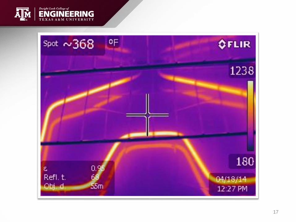
Experimentation and Testing
• Interested in how the camera
perceives high temperatures.
• Emissivity and distance set for
316 stainless steel at 5 meters.
• Does not read air temperature!
• Results are appropriate.
• Impressive distinction between
high temperature and very high
temperature. (over 1000ºF)16
17

Daily Operation of Nuclear Facilities
• Daily monitoring of nuclear facilities in order to make the robot more
economically feasible.
• Mapping and monitoring of steam lines during normal operation in order
to determine where leaks may be present.
• Use thermal data to better insulate locations of significant heat loss.
(Resulting in energy loss in the steam)
18
Experimentation and Testing
19
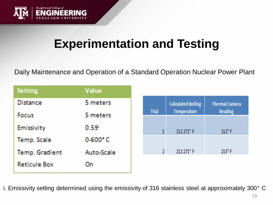
Daily Maintenance and Operation of a Standard Operation Nuclear Power Plant
i. Emissivity setting determined using the emissivity of 316 stainless steel at approximately 300° C

Experimentation and Testing
20

Nice to Have Design Features
• Ability to obtain accurate temperature measurements from long ranges for use in aerial drones.
• Applicable in level 6-7 events where containment/facility structures have severe damage.
• Moderate distances do not appear to affect the temperature readings.
21

Temperature Accuracy Testing
Thermometer vs. Thermal Camera
• A glass of room temperature
water was used to compare
temperature readings.
• Interested in the proper
emissivity settings and how
distance effects temperature data
point gathering
• The distance from the object
does not change the temperature
reading.
• We know that the settings are
appropriate!
22

Main Objective for Detectors: John Contreras
• A supporting cast of ranging detectors will be optimized
in order to be used with the main camera system to
provide meaningful data to the user.
• Coding the detectors uploading capability to be more
informative when existing with a camera system then
simply by hand.
• Have ample amount of data collection to allow engineers
to be able to make decisions regarding safety analysis.
23

• Kinect is a line of motion sensing input devices by Microsoft for Xbox
360 and Xbox One video game consoles and Windows PCs
• Kinect has a two camera overlay system. Using 3-D, thermal, and an
infrared sensor as its camera optics.
• Kinect builds on software technology developed internally by Rare,
which developed a system that can interpret specific gestures, making
completely hands-free control of electronic devices possible by using
an infrared projector and camera and a special microchip to track the
movement of objects and individuals in three dimensions.
24

MAESTRO MCA Emulation Software• The spectrum window is often the primary
user focus when using MAESTRO and up
to eight live detectors and eight saved
spectra can be displayed concurrently.
• When viewing a live detector, the spectrum
view is updated in real time and provides
current spectral data, live peak calculations,
and hardware properties
• The interface between hardware and
software is provided through the ORTEC
CONNECTIONS framework. This
application layer encompasses all of the
hardware drivers and communication
protocols that are necessary for software
applications to control the MCB
instruments.
25

MAESTRO MCA: Advanced Functions
• Nuclide identification from libraries
tailored to the application, isotope
markers that show the location of
the library energies and an
assumption driven estimation
occurs to confirm its identity.
• A very important factor is the
ability to control number of
channels averaged to determine
background through multiple
selection of detectors.
• Using the Mariscotti Peak search
to locate areas of interest is done
internally
26

MAESTRO MCA: Sample Data Acquisition
• Sample environment showing a spill inside a
contained area, allows the concentration to show
by calculating 1/R as the count rate decreases
exponentionally.
• Quality of results increase as the
knowledge of the program and
detector increased. Much more
efficient at gathering data as well.27

28

• Using FLUKA which is a Monte Carlo simulation package
used for interaction between transport and interaction of
particles and nuclei in matter
• Defining the parameters of conditions that can generally be
seen in plant operations.
Lead Glass Concrete Human Units
Particle Numbers 1500 1500 1500
Thickness 5 20 30 cm
Height 100 200 60 cm
Width 100 200 28 cm
Density 3.1 2.35 1 g/cm3
29

Energy in Glass 5.78E-02 GeV/cm3/particle → 8.66E+01 GeV/cm3
Energy Escaped 1.88E-01 GeV/cm3/particle → 9.41E-01 GeV/cm3
Dose of Glass 4.30E-05 Gy → 4.30E+01 mrem
Energy in Concrete 0.236202 GeV/cm3/particle → 354.3024 GeV/cm3 → 2.83E+08 GeV
Energy Escaped 0 GeV/cm3/particle → 0 GeV/cm3 →
Dose of Concrete 0.000133 Gray → 133.3989 mrem
FLUKA Simulation Analysis• Sample environment using samples of lead that can be found after some type
of accident.
• Sample exposure to actual environment on a small 10ft x 10ft scale to show
evidence of actual radiation leak exposure.
30

Scintillation Parameters
• Luminescent
materials, when struck
by an incoming
particle, absorb its
energy and scintillate
energy in the form of
light.
• PMT's absorb the light
emitted by the
scintillator and reemit it
in the form of electrons
via the photoelectric
effect.
31

• The detector above is known as the
digiBASE-E High Performance, Ethernet
All-In-A-PMT-Base Digital Gamma
Spectrometer.
• This detector is optimized for the ranges
that the autonomous vehicle would be
exposed to using PoE to power the
device this solves part of the energy
issue we were having
• The Multi-channel Analyzed is the main
driving force in the detector analysis portion of
the project.
• Analyzing a stream of voltage pulses and
sorts them into a histogram or spectrum of
number of events versus pulse-height which
may often relate to energy or time.
32

33

• Being able to appropriate results calibrated to a video recording device,
that allows enough data points to provide a meaningful simulation for the
viewer.
• The detectors would not be able to operate at 100% efficiency with this
since ideal placement and location would not be so easily accessible.
• The range of detectors available had to meet certain criteria: portability,
Wi-Fi application, resistance to point radiation, data acquisition software.
• All our current efforts have been bettered with increasing technology,
cheaper material costs and finally more cohesive interactions between
different detectors
34

Detectors
• To have a reasonable detector network that can co-exist
with the MRV and provide useful and accurate data to be
used in a safety analysis.
• To have absolute synchronization with the detector network
we created, to be able to identify issues within the
environment itself and adjust its course of action
• The software and coding that has been created for the project serves as more
than just a guideline and actually is the most accurate and easily accessible way
to establish the parameters in the environment or routine scans.
• On expanding the detector network and what results are able to be seen and
possibly predict what occurs within a few hours after accidents. Having an
understanding of the basic programs and functions during the first portion of the
project will lead to very significant results in the second portion as the software
had very large learning curve and provide a large amount of errors with little
outside help.
Xbox One Kinect (2013)
35
Integration of Parts
• Since the Kinect is the focal point of the project, it seemed most fitting if the code was altered to integrate the other parts of this project
• Several ideas were made: overlaying ,map “pings”, and screen shotting but none of these proved to be adequate
• The overlaying method involved having the outputs from the thermal camera and MRPT “sitting” on top of each other
• This proved to be very difficult since the MRPT’s output is not in the form of a video feed. It was then considered to try “coloring” the MRPT output map with the images from the thermal camera but that would involve directly interfacing with the camera through coding
36

Integration of Parts Cont.
• The map “pings” idea involved placing markers on the map whenever the user hit a certain key on the keyboard. Different keys would place different colored pings on the map to indicate different things found such as abnormal thermal gradients or radiation
• This proved unsuccessful for two reasons: if the pings became a part of the map, the MRPT could draw over it again if the Kinect were to look in the direction of where the ping was placed. If the ping were arbitrarily floating over the map, the ping would become misrepresentative of the desired location as the model became scaled down
• The final thought was to use a system of screen shotting. The user could take a screen shot of the model whenever they wanted by using a key. They could do this for a number reasons including detecting something abnormal from the detectors or to keep a log of every room the device passes through
37

Future Work
• This project has plenty of potential to be used in the real world and as it sits, it isn’t too far from that
• In order to properly integrate the different devices, all the parts would need to be able to interact with the MRPT code through device drivers. This implies that all of the necessary drivers would need to be made since neither of the other devices used came with the drivers needed
• If this can be done, the program will be able to access data from each of them as it would the Kinect. It could handle placing static markers on the map on its own without user intervention
38

Deployment Analysis
• Radiation Damage to Electronics
• High Temperature Electronics
• Accident Environment Analysis
• Shielding Requirements
• Cost Analysis
39

Radiation Damage to Electronics
Three typical radiation effects
• Physical effects- disruption of a material by the displacement of atoms within a crystal. Such as the reduction in the amplification factors of transistors
• Chemical effects- breaking of chemical bonds or the formation of new bonds due to radiation. These chemical effects can cause material to undergo changes. Such as rolled paper expanding out of its case in a capacitor due to radiation degradation of the oil.
• Ionizing effects- creates electrical paths that allow electric charges to break down isolations and barriers. Such as leakage currents of insulators or semiconductors that can be large and temporary.
40

Radiation Damage to
Electronics
• Study from ASTRA research reactor in Seibersdorf, Austria. Table shows the sensitivity of electronics to gamma radiation (60Co source).
• Majority of components are stable to an absorbed dose of 1000 Gy.
• At 109 Gy, most components no longer operate.
• Want to account for the lowest dose that causes damage.
41

High Temperature Electronics
• High temperature use is categorized to be above 150 °C which ,in the case
of fires/explosions/core melt, is very easily reached.
• Below is a table with Max Rated Temperatures of a few electronic
components.
• Therefore, want to keep temperature below 175 °C or provide thermal
shielding.
42

Accident Environment Analysis
• Based on the International Nuclear Event Scale created by the IAEA
• Provides basic on and offsite implications of various level incidents/accidents
43

Accident Environment Analysis
Level 7: Case Study-Chernobyl NPP
• External release quantities are radiologically equivalent to more than 10,000’s TBq of Iodine-131. (Multiplication factor for other relevant isotopes)
• Extreme Damage to the installation
• High on-site dose rates (.03-300 Sv/hr)- No radiation detectors survived the accident. These reading were taken shortly after with a portable device.
• Thermal Considerations: Steam explosion, fire and core material released
44

Accident Environment Analysis
Level 6 : External release radiologically equivalent to 1000’s to 10,000’s of TBq 131I. (The Kyshtym Disaster)
Level 5 : External release radiologically equivalent to 100s to 1000’s of TBq 131I. (Three Mile Island)
• Severe to significant installation damage
• High on-site radiation levels (not as severe off-site)
• Thermal Considerations: Explosion, fire, partial core melting
45

Accident Environment Analysis
For lower level accidents/incidents(4-1):
• Little to no offsite release of radioactive material
• Level 4- Overexposure with likelihood of early
death
• Level 1- Exceed annual worker dose limit
• Installation damage not severe.
46

Accident Environment Analysis
Rating
Level Radiation Onsite
External Radiation
Release Thermal Considerations
7
High: Chernobyl Dose Rates
ranged 300-0.03 Sv/hr 10,000's TBq
Core Melting, LOCA, Explosions
and/or Fire
6 High 1000's-10000's TBq
Core Melting, LOCA, Explosions
and/or Fire
5 High: 370 Ebq in containment 100's-1000's TBq
Partial Core Melting, LOCA,
Explosions and/or Fire
4 1000's TBq in Primary few mSv
Partial Core Melting, LOCA,
Explosions and/or Fire
3 1000's TBq in Secondary .01mSv Normal Op
2 50 mSv/hr None Normal Op
1 Exceed Worker annual Limits None Normal Op
0 None None Normal Op
47

Shielding
Revisiting Level 7-
Chernobyl Accident
• Using Rad Pro
Calculator
• Desired Dose
rate set to
background
• For electronics,
dose rate can be
significantly
higher than
background
LocationSieverts per
hour (SI Unit)
Shielding (Lead in cm)
required for desired dose rateConcrete in cm
Vicinity of the reactor
core300 12.4 80.8
Fuel fragments 150–200 11.8-12 77.2-78.7
Debris heap at the
place of circulation
pumps
100 11.5 75.2
Debris near the
electrolyzers50–150 11-11.8 71.6-77.2
Water in the Level +25
feedwater room50 11 71.6
Level 0 of the turbine
hall5–150 9.2-11.8 60-77.2
Area of the affected
unit10–15 9.7-10.1 63.5-65.5
Water in Room 712 10 9.7 63.5
Control room 0.03–0.05 5.2-5.6 35.5-37.8
Hydropower
Installation0.3 7 46.3
Nearby concrete
mixing unit0.10–0.15 6.1-6.4 41.1-43
48

Rad Pro Calculator
49

Issues with Shielding
• Radiation readings will not be accurate if shielding included
• Thermal readings will not be accurate with shielding
• The best radiation shielding materials are the worst at thermal shielding
• The best thermal shielding material requires a lot more shielding
50
Thermal
Conductivity of
Lead is 34.7 W/m
K
Thermal
Conductivity of
Concrete is 0.8
W/m K

Cost Analysis
Component Cost
Microsoft Kinect $150
FLIR Thermal Imager $4000-8000(Resolution)
Radiation Detector $1200
Total Cost of Imaging Device Only $5350-9350
51

Cost Analysis
Probabilistic Approach. Actual cost
will depend greatly on the robotics
used.
52

Cost Analysis
53

JOHN CONTRERAS - Detectors
• To have a reasonable detector network that can co-exist with the
MRV and provide useful and accurate data to be used in a safety
analysis.
TYLER CULLERO – Algorithm Analysis
• To allow the syncing of the image capture system to overlay
its data to depict a useful 3-D environment where the detector
portion can interact and associate values on the output video.
ALEX PARKER – Thermal Analysis
• To be able to overlay the image results from the thermal
analysis and have them synchronize using some type of time-
dependent analysis that can interact with the set of algorithms.
NICHOLE MCCOY- Deployment Analysis
• To optimize the design by exploring various level
events. This will provide thermal and radiation
ranges that the device could be exposed to and
provide a basis for shielding requirements. 54

AcknowledgementsWithout the help of these individuals our project would have not been the amazing
journey and experience we were all able to go through the semester, so thank you
all for your input and knowledge.
Dr. Cable Kurwitz Texas A&M Technical Advisor
Dr. Karen Vierow Texas A&M Associate Professor
Rodolfo Vaghetto Texas A&M
55
References
• 1. "Discover MRPT." MRPT.org. Web. 16 Apr. 2014.
• 5."Kinect for Windows SDK Beta Launches, Wants PC Users to Get a Move on."Engadget. Web. 16 Feb. 2014. <http://www.engadget.com/2011/06/16/microsoft-launches-kinect-for-windows-sdk-beta-wants-pc-users-t/>.
• 6. "Microsoft Releases Kinect for Windows SDK." Latimes.com. Web. 16 Feb. 2014. <http://latimesblogs.latimes.com/technology/2011/06/microsoft-releases-kinect-for-windows-sdk.html>.
• 7. "DepthImageFormat Enumeration." Microsoft. Web. 16 Apr. 2014. <http://msdn.microsoft.com/en-us/library/microsoft.kinect.depthimageformat.aspx>.
• 8. Peter Henry, Michael Krainin, Evan Herbst, Xiaofeng Ren, Dieter Fox. RGB-D Mapping: Using Depth Cameras for Dense 3D Modeling of Indoor Environments. International Symposium on Experimental Robotics, 2010. Print.
• 9. Automatic Radiation Detection and Monitoring System.
• 10. S. Moser, W. Harder, C. Hurlbut, and M. Kusner "Principles and Practice of Plastic Scintillator Design.” Radiation Physics and Chemistry 41.1-2(1993): 31-36.
• 11. Knoll, Glenn F. Radiation Detection and Measurement. New York: Wiley, 2000.Print.
• 12. J. Guo “Comparison of the performance of different converter for neutron radiography and tomography using fission neutrons.” Nuclear Instruments and Methods in Physics 605.1-2 (2009): 69-72.
• 13. Gilmore, Gordon, and John D. Hemingway. Practical Gamma-ray Spectrometry. Chichester: John Wiley, 1995. Print.
• 14. S. Battisti, R. Bossart, H. Schonbacher and M. Van de Voorde. “Radiation Damage to Electronic Components.” Nuclear Instruments and Methods 136.3 (1976): 451-472.
• 15. R. Lipton. “Radiation Damage in Detectors and Electronic.” Nuclear Instruments and Methods 130.1 (1975): 291-300.
• 16. J. Watson and G. Castro. High-Temperature Electronics Pose Design and Reliability Challenges. Analog Devices, Apr. 2012. Web. Mar. 2014. <http://www.analog.com/library/analogdialogue/archives/46-04/high_temp_electronics.pdf.>
• 17. International Atomic Energy Agency. The International Nuclear Event Scale User’s Manual Vienna: IAEA, 2001. Print.
• 18. International Atomic Energy Agency. Generic Procedures for Monitoring in a Nuclear or Radiological Emergency. Vienna, Austria: IAEA, 1999. Print
• 19. G. MEDVEDEV.”JPRS Report: Soviet Union Economic Affairs Chernobyl Notebook.” Foreign Broadcast Information Service. June 1989. Web. 16 Apr. 2014. <http://handle.dtic.mil/100.2/ADA335076>.
• 20. D. Soran, D. Stillman. "Analysis of the alleged Kyshtym disaster."Los Alamos National Lab” Web. 16 Feb. 2014. < http://www.iaea.org/inis/collection/NCLCollectionStore/_Public/14/724/14724059.pdf>.
• 21. Vierow, K. NUEN406&410 Design of Nuclear Reactors Course Notes. Department of Nuclear Engineering : Texas A&M University, 16 Apr. 2014.
• 22. "Consejo De Seguridad Nuclear(Spanish Office of Nuclear Safety)."International Atomic Energy Agency (IAEA). Web. 16 Feb. 2014. <http://www.csn.es/descarga/NWASCO140408.pdf>.(IN SPANISH)
• 23. "Report on the preliminary fact finding mission following the accident at the nuclear fuel processing facility in Tokaimura, Japan."International Atomic Energy Agency (IAEA).1999. Web. 16 Feb. 2014.
• 24. McGinnis, Ray. "Rad Pro Calculator: Gamma Activity, Dose Rate and Shielding Calculator." Web. 16 Apr. 2014. <http://www.radprocalculator.com/Gamma.aspx>.
56

QUESTIONS?
57