resource road rehabilitation handbook: planning...
TRANSCRIPT
Resource Road Rehabilitation Handbook:Planning and Implementation Guidelines
(Interim Methods)
by
G.D. Moore
Watershed Restoration Technical Circular No. 3July 1994
Funded by:
Watershed Restoration ProgramMinistry of Environment, Lands and Parks
and Ministry of Forests
The formatting and images in this document may vary slightly from the printed version.

Acknowledgments Interim Methods: July 1994 L
Acknowledgments
The material in this handbook is based in part on an unpublished draft reportdeveloped by a technical working committee comprised of ministry, forestindustry and environmental agency representatives. Members of thatcommittee included: Don Dobson of Dobson Engineering, Bill Rand of WestFraser Mills Ltd., Ron MacLeod of MacMillan Bloedel Ltd., John Lamb ofFisheries and Oceans Canada, Dwain Boyer of Ministry of Environment,Lands and Parks, and Marty Osberg, Gary Zsomber, and Glenn Moore of theMinisty of Forests. This committee’s early work was revised (in some partsextensively) and expanded to address the increased scope of the WatershedRestoration Program.
The author wishes to thank the following people for their helpful suggestionsand comments during the preparation of this interim handbook: FrankBaumann and Doug VanDine, consultants; Glynnis Horel of MacMillanBloedel Ltd.’s Woodlands Services Division and Don Jones of TimberWestForest Ltd.’s South Island Region; and Norm Brook, Brian Chow,Carl Erickson, Bela Hirczy, Ron Jordens, Younas Mirza, Ken Nelson andRon Poets of the Ministry of Forests. The Preface of the handbook waswritten by Tom Johnston of Fisheries Branch, Ministry of Environment,Lands and Parks.
Much of the word processing was provided by Linda Turnbull of the Ministryof Forests; her efforts are greatly appreciated. Many thanks are due to staff atInternational Wordsmiths Ltd. for their assistance in editing and formattingthe text excluding the appendices. Thanks also go to Technical andAdministrative Services Branch, Ministry of Forests, for arranging productionand distribution of the handbook.
The author is also grateful for permission to reproduce the following material.
• Figures 1 and 2 are based on the work of Dan Hogan, Research Branch,Ministry of Forests
• Photographs in Appendices A, B and C are courtesy of Forest Sciences,Vancouver Forest Region, Ministry of Forests
• The Road Rehabilitation Plans for the Theodosia and Dalgiesh areas andthe Mamquam River Road Deactivation Plan in Appendix I arereproduced courtesy of MacMillan Bloedel Limited, Woodlands ServicesDivision
• Document 2 of Appendix H, and Appendix J, are reprinted courtesy of theauthor, W.E. Weaver, Pacific Watersheds Associates, Arcata, California

Preface Interim Methods: July 1994 LL
Preface
The Watershed Restoration Program (WRP) is an initiative under theprovincial Forest Renewal Plan to restore the productive capacity of fisheries,forest and water resources that have been adversely impacted by past forest-harvest practices. The goals of the Water Restoration Program are:
• to restore, protect, and maintain fisheries, aquatic, and forest resources thathave been adversely impacted by forest-harvesting practices and thatwould require several decades to recover naturally
• to provide community-based employment, training, and stewardshipopportunities throughout the province
• to provide a mechanism to bridge historical forest harvesting practices andthe new standards established by the Forest Practices Code by diversifyingjobs in the forest sector.
This manual is one of a series to assist in planning programs to restorewatersheds. Watershed restoration attempts to re-establish conditions moresimilar to those found in unimpacted watersheds by altering the rates of theprocesses that control the physical and biological structure of watersheds. Assuch, it encompasses activities ranging from hillslope stabilization and roadrehabilitation to riparian revegetation and fish habitat improvement.
This series of manuals provides a common set of techniques to assessopportunities for restoration activities. The first two manuals provide anoverview of the planning process and the assessment process for determiningthe current state of the watershed. The remaining manuals describeprocedures for assessing specific watershed components in more detail andspecify activities and standards to assist rehabilitation of watersheds. Thetitles in the series are:
• Planning and Assessment Procedures for Watershed Restoration Projects• Watershed Assessment Procedure (Interim Methods)• Resource Road Rehabilitation Handbook (Interim Methods)• Forest Site Rehabilitation for Coastal British Columbia (Interim Methods)• Gully Assessment Procedure for British Columbia Forests (Interim
Methods)• Riparian Assessment Procedures (Interim Methods)• Stream Channel Assessment (Interim Methods)• Fish Habitat Assessment (Interim Methods)

Preface Interim Methods: July 1994 LLL
In planning restoration activities, it is important to recognize the linkagesamong the various physical and biological subcomponents of watersheds andto integrate activities to ensure their successful implementation. Although themanuals treat particular aspects of watershed restoration separately, youshould use them together to develop an integrated program that considersactivities for the entire watershed and proceeds successively from thehillslopes to the floodplain to the riparian area to the stream channel.
Many WRP (preliminary) assessment procedures overlap with procedures thatwill be required as part of the new Forest Practices Code (FPC). When theForest Practice Code manuals are published, beginning in fall 1994, they willsupersede the WRP manuals.
Table of Contents Interim Methods: July 1994 LY
Table of Contents
Introduction ................................................................................................... 1
Organization of the Handbook .......................................................................... 1
Overview of the Watershed Rehabilitation Process.......................................... 2
Problems Caused by Abandoned Resource Roads............................................ 6
Overview of the Road Rehabilitation Process................................................... 7
Step 1: Planning Project Objectives ........................................................... 9
Identifying Project Planning Priorities by Zone................................................ 9
Preparing Road Inventory Base Maps............................................................. 10
Identifying Access Needs................................................................................ 12
Identifying Access Management Strategy....................................................... 13
Defining Project Scope and Objectives for the Zone...................................... 16
Step 2: Conducting Field Assessments ..................................................... 20
Recommended Qualification of Field Inspection Staff................................... 20
Level I Field Assessment ................................................................................ 21
Level II Field Assessment (Mandatory).......................................................... 27
Step 3: Preparing Reports and Maps....................................................... 36
Level I Field Assessment Report .................................................................... 36
Level II Field Assessment Report ................................................................... 37
Step 4: Implementing the Project ............................................................. 40
Scheduling Implementation of Site Works ..................................................... 40
Site Works Supervision................................................................................... 40
Step 5: Monitoring and Evaluating Results............................................. 41
Additional Sources of Information............................................................ 42
Table of Contents Interim Methods: July 1994 Y
Bibliography ................................................................................................ 44
Feedback Request Form ............................................................................. 47
Appendix A: Typical Mechanisms of Road-Associated Erosion and Sediment Production
Appendix B: Explanation of Some Road Deactivation Measures
Appendix C: Tschaplinsky, P. J. (1992). Effects of Roads on Freshwater Fish Habitats andFish Production. Victoria, British Columbia: Research Branch, B.C.Ministry of Forests
Appendix D: Types of Resource Roads, Logging Trails, and Permits
Appendix E: British Columbia. B.C. Ministry of Forests (1993). Risk AssessmentProcedure. Engineering Manual – Chapter 8. Victoria, British Columbia:Engineering Section, Timber Harvesting Branch (pp. 7-20)
Appendix F: Example Road Inspection Forms
Appendix G: British Columbia Forest Practices Code (Draft) Standards, May 1994 forRoad Maintenance and Deactivation
Appendix H: Document 1British Columbia. B.C. Ministry of Forests (1992-1993). Road Construction,Maintenance and Deactivation Handbook. Burnaby, British Columbia:Engineering, Vancouver Forest Region.
Document 2Weaver, W. E. and D. K. Hagans (1990). Techniques and costs for effectiveroad closure, Technical paper #90-1. Arcata, California: Pacific WatershedsAssociates
Appendix I: Examples of Road Deactivation Reports and Maps
Appendix J: Waver, W.E. and R.A. Sonnevil (1984). Relative cost-effectiveness of erosioncontrol for forest land rehabilitation, Redwood National Park, In: ErosionControl…Man and Nature, Proceedings of Conference XV, InternationalErosion Control Association, February 23 and 24, 1984, Denver, Colorado,pp. 83-115

Resource Road Rehabilitation Handbook
Introduction Interim Methods: July 1994 1
Introduction
Organization of the Handbook
This handbook is divided into six sections. The Introduction gives anoverview of:
• the contents of the handbook• the problems caused by abandoned resource roads• the process for rehabilitating resource roads.
The remaining sections give more detailed descriptions of each of the steps inthe rehabilitation process.
Contents of the Handbook
Resource road rehabilitation is the upgrading of resource roads1 to currentstandards, or the deactivation of resource roads to one of three levels—temporary, semi-permanent, or permanent. This handbook provides technicalinformation and methodologies to help plan and organize resource roadrehabilitation projects in areas of past timber harvesting activities, and in areasof other past resource management activities (e.g., mining, mineral claim, andpetroleum development). Although the emphasis is on rehabilitatingabandoned roads, many of the techniques and processes described apply toabandoned logging trails and to active and permitted, resource roads andlogging trails.
This handbook is designed primarily for registered professionals and forestrytechnologists qualified in resource road engineering, hydrology, and landslidehazard assessment. It focuses on:
• preventing and remedying soil erosion, landslides, and streamsedimentation hazards resulting from resource roads
• restoring hillslope hydrology
________________________1 Resource roads are forest roads, mining and mineral claim access roads, and petroleumdevelopment roads. Forest roads are Forest Service Roads and Operations roads built for useby logging trucks to transport logs and other forest products from a landing to a reloading siteor conversion facility. Do not confuse forest roads with logging trails – see Appendix D fordefinitions of logging trails.
Resource Road Rehabilitation Handbook
Introduction Interim Methods: July 1994 2
• restoring some road sites to productive forest land.
In addition, this handbook contains the following information to help youidentify problems on roads and prescribe treatments to remedy them:
• a process to assign work priorities for corrective action based on thedegree of risk to the environment and other values
• a methodology for thoroughly and consistently examining road prisms anddrainage structures
• a suggested process to record problems and deficiencies along the roadright of way, and existing or potential off-site impacts on the environmentand on other resources
• a suggested format for presenting inventory map information, andpreliminary time and cost estimates
• a list of site factors to evaluate during the prescription phase of detailedroad deactivation planning
• operational strategies for implementing field projects, and planning tipsfor supervising and monitoring physical remedial works.
Overview of the Watershed Rehabilitation Process
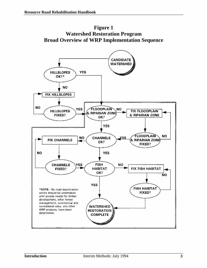
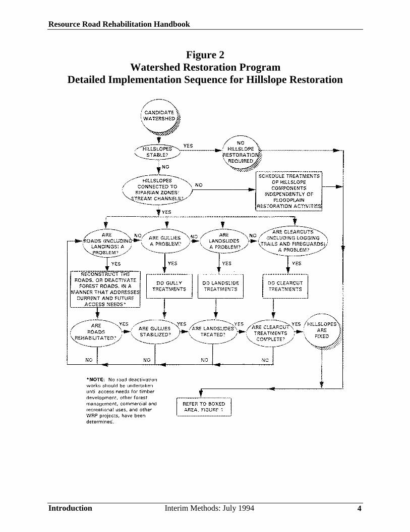
Watershed restoration activities are designed to speed the recovery ofenvironmental values in watersheds that have been degraded by past resourcemanagement activities. The rehabilitation of logging-degraded hillslopes andvalley flats or floodplains must progress in a logical manner to ensure thesuccess and cost effectiveness of the overall Watershed Restoration Program.Therefore, rehabilitation activities must follow a sequential, top downimplementation approach, as illustrated in Figures 1 and 2.
The following questions clearly demonstrate the key links between restorationactivities and the importance of carrying out remedial works on roadsaccording to the need for current and future access.
Resource Road Rehabilitation Handbook
Introduction Interim Methods: July 1994 3
Figure 1Watershed Restoration Program
Broad Overview of WRP Implementation Sequence
Resource Road Rehabilitation Handbook
Introduction Interim Methods: July 1994 4
Figure 2Watershed Restoration Program
Detailed Implementation Sequence for Hillslope Restoration
Resource Road Rehabilitation Handbook
Introduction Interim Methods: July 1994 5
Hillslope Components
• Are there existing or potential problems with hillslope components suchas upper, middle, and lower slope roads (including landings), gullies,landslides, and clear cut areas (including logging trails and fireguards)?
• Do any hillslope components threaten human life?
• Do any hillslope components threaten resource values, such as communitywater supplies and water quality, fish habitat, landscape aesthetics, timbergrowing site productivity, and recreational values?
• Are hillslope components connected to riparian zones or stream channels?If so, treat hillslope components before restoring stream channels and fishhabitat; if not, you can schedule treatments of hillslope componentsindependently of valley flat or floodplain restoration activities.
• Is access required now or in the future for logging, forest, or otherresource management, commercial and recreational activities?
• Have stakeholder groups reviewed and approved access requirementsbefore approval of road rehabilitation projects and other proposed WRPprojects:
Valley Flat and Flood Plain Areas
• Are there any existing or potential problems with valley flat or floodplainareas?
• Are there problems with roads on the valley flat or floodplain? Is accessrequired now or in the future for logging, forest, or other resourcemanagement, commercial and recreational activities?
• Have stakeholder groups reviewed and approved access requirementsbefore approval of road rehabilitation projects and other proposed WRPprojects? If so, rehabilitate the roads.
• Has the riparian zone recovered? Is the floodplain stable? Are streamchannels stable? If not, repair the riparian zone and stabilize floodplainsand stream channels next. Finally, restore and mitigate lost habitat instream channels, or if stable, conduct necessary off channel habitatimprovement activities.
Resource Road Rehabilitation Handbook
Introduction Interim Methods: July 1994 6
Problems Caused by Abandoned Resource Roads
While many resource roads are needed on a long-term basis to manage forestresources, a significant number are not required when resource managementactivities end. Today, it is recognized that roads and their associateddevelopments, such as landings, logging trails, fireguards, and civil structures,must be deactivated2 when they are no longer maintained or used. However,in the past, many roads were simply abandoned after use and were notdeactivated; these untreated and industrially inactive roads belong to acategory of resource roads called abandoned resource roads.
Abandoned resource roads are not under active permit, such as a Road Permit,Road Use Permit, Cutting Permit, or Special Use Permit and are notmaintained by the forest licensees, the Ministry of Forests, mining andmineral claim companies, or by petroleum development companies. On suchroads, there is usually no organization allocating resources to maintain theintegrity of road cuts, fills, and drainage works, or to close the roads foraccess management and safety purposes. Consequently, many abandonedresource roads have been left unattended and have deteriorated over time.
In their current deteriorated condition, many abandoned resource roads havethe potential to trigger landslides, produce sediment, and cause sedimentationof streams, particularly where they traverse steep and sensitive terrain.Appendix A, Typical Mechanisms of Road-Associated Erosion and SedimentProduction, describes the most common problems encountered on roads.Impacts recorded in the past have included damage to water quality, watersupply systems, fish habitat, landscape aesthetics, site productivity, privateproperty and utilities, and threat to human life. Natural erosion anddeterioration processes have also weakened bridges, major culverts andretaining walls, and other related civil structures.
________________________2 The purpose of deactivating roads is to minimize the risk of road-related failures, such aslandslides, surface soil erosion, and stream sedimentation. Road deactivation measures give aroad system a number of basic failsafe water control elements and road prism constructionmodifications. These are designed to maintain the integrity of the environment, control accessfor safety and natural resource conservation, and protect the road investment itself whenfuture vehicle access is planned, during the times that use or maintenance of the road issuspended.
Resource Road Rehabilitation Handbook
Introduction Interim Methods: July 1994 7
A large inventory of abandoned road networks in the provincial forests needto be either upgraded to current standards or deactivated to an appropriatelevel to prevent potential road-related environmental damage. If you areunfamiliar with road deactivation measures, refer to Appendix B, Explanationof Some Road Deactivation Measures. Appendix C, Effects of Roads onFreshwater Fish Habitats and Fish Production provides a comprehensivediscussion of impacts of hydrological effects and increased levels ofsedimentation on fish habitat, and points out the importance of roaddeactivation.
Overview of the Road Rehabilitation Process
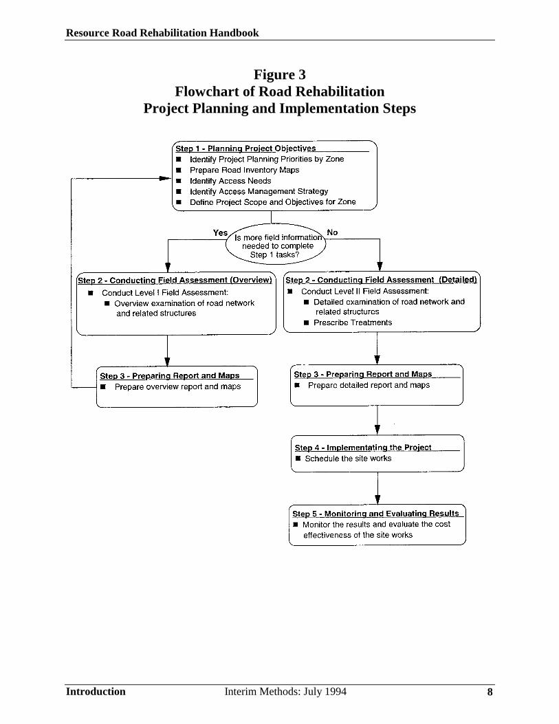
Recognized, qualified personnel must assess each road rehabilitation projectindividually and plan and organize it according to the following steps (seeFigure 3):
• Step 1:Planning project objectives• Step 2:Conducting field assessments• Step 3:Preparing reports and maps• Step 4:Implementing the project• Step 5:Monitoring and evaluating results
Resource Road Rehabilitation Handbook
Introduction Interim Methods: July 1994 8
Figure 3Flowchart of Road Rehabilitation
Project Planning and Implementation Steps
Resource Road Rehabilitation Handbook
Planning Project Objectives Interim Methods: July 1994 9
Step 1: Planning Project Objectives
This first step involves five tasks:
1. Identifying project planning priorities by zone.2. Preparing road inventory base maps.3. Identifying access needs.4. Identifying access management strategies.5. Defining project scope and objectives for each zone.
Identifying Project Planning Priorities by Zone
Rehabilitating forest roads in areas of past harvesting is a large scale initiativethat can be quite complex in scope. To make planning and implementing suchprojects manageable, divide large land management areas into manageable“zones,” by watershed, well-defined geographical boundaries, specific roadnetworks, or other logical means.
Within a particular zone of interest, you should not begin detailed fieldexamination of roads unless you have prepared road inventory base maps andclearly identified the project scope and objectives. The maps should show thelocations of existing active and abandoned roads, the current and future accessneeds, and other pertinent information (see Preparing Road Inventory BaseMaps below).
You determine the highest priority zones for planning inventory mapping andfield assessments based on the potential risk that abandoned road networkspose to the environment and social and economic values. Local knowledge ofproblem sites and recognition of special concerns should also play major rolein prioritizing zones. It is often efficient to carry out fly-overs using fixedwing aircraft or helicopters to establish or confirm zone priorities (see Level IField Assessment in Step 2: Conducting Field Assessments).
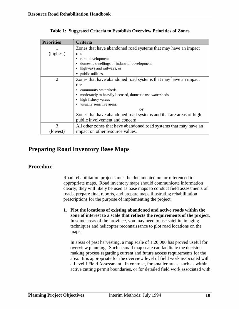
The rating system in Table 1 may help you prioritize zones for planningpurposes.
Resource Road Rehabilitation Handbook
Planning Project Objectives Interim Methods: July 1994 10
Table 1: Suggested Criteria to Establish Overview Priorities of Zones
Priorities Criteria1
(highest)Zones that have abandoned road systems that may have an impacton:• rural development• domestic dwellings or industrial development• highways and railways, or
• public utilities.
2 Zones that have abandoned road systems that may have an impacton:• community watersheds• moderately to heavily licensed, domestic use watersheds• high fishery values• visually sensitive areas.
orZones that have abandoned road systems and that are areas of highpublic involvement and concern.
3(lowest)
All other zones that have abandoned road systems that may have animpact on other resource values.
Preparing Road Inventory Base Maps
Procedure
Road rehabilitation projects must be documented on, or referenced to,appropriate maps. Road inventory maps should communicate informationclearly; they will likely be used as base maps to conduct field assessments ofroads, prepare final reports, and prepare maps illustrating rehabilitationprescriptions for the purpose of implementing the project.
1. Plot the locations of existing abandoned and active roads within thezone of interest to a scale that reflects the requirements of the project.In some areas of the province, you may need to use satellite imagingtechniques and helicopter reconnaissance to plot road locations on themaps.
In areas of past harvesting, a map scale of 1:20,000 has proved useful foroverview planning. Such a small map scale can facilitate the decisionmaking process regarding current and future access requirements for thearea. It is appropriate for the overview level of field work associated witha Level I Field Assessment. In contrast, for smaller areas, such as withinactive cutting permit boundaries, or for detailed field work associated with
Resource Road Rehabilitation Handbook
Planning Project Objectives Interim Methods: July 1994 11
a Level II Field Assessment, we suggest a map scale of 1:5,000. (See Step2: Conducting Field Assessments for descriptions of Level I and Level IIField Assessments.)
2. Name or number all roads plotted on maps sheets for identificationpurposes.
3. Plot the locations of road-related landslides. Also identify andhighlight stream systems, gullies and community water supplies, andoutline the perimeter boundaries of any developed areas that are accessedby the road system (e.g., cutblocks, recreation areas, mines, etc.)
4. Document the recommended access management strategy for eachroad. (See Identifying Access Management Strategy).
5. Gather information on both timber and non-timber values adjacent toand downslope of the road networks. It is useful to overlay thisinformation, and other existing resource management information (streamclasses and terrain classes) directly on the map sheets.
Sources of Information
Sources of information to prepare road inventory base map sheets mayinclude:
• forest cover maps• TRIM (Terrain Resource Information Management) topographic maps• other topographic maps• current aerial photographs• Forest Development Plans• Access Management Plans• community watershed maps• water rights maps• terrain stability maps and reports• soils maps• current Coordinated Access Management Plan (CAMP) Maps• Forest District tenure maps• specialist reports and studies• plans that show access needs for future timber harvesting and silviculture
activities• other reports, maps and information.
Resource Road Rehabilitation Handbook
Planning Project Objectives Interim Methods: July 1994 12
Note: If 1:20,000 scale reference maps are not available use 1:50,000 scalemaps. The 1:50,000 scale maps may be enlarged to a 1:20,000 scale forpreparing road inventory base maps.
Identifying Access Needs
Once the road inventory base maps are prepared, you can begin to establishcurrent and future access needs for the zone. This process called “accessmanagement planning” is explained in British Columbia Institute ofTechnology (BCIT) course manual, “Forest Road Deactivation RRET 410.”It requires you to answer several questions:
• What types of vehicles currently use the road? Example: heavy trucks,light trucks, no apparent vehicle use. Why is the road currently used andwho uses it?
• Which roads are currently required? Which roads are required in thefuture? Who requires them?
• Which organizations are interested in maintaining and inspecting the roadother than the Ministry of Forests?
• How can all the various interest groups best be accommodated?
• What are the short and long-term budget requirements for road inspectionsand maintenance? Can the roads required for access be physically keptopen over the period of planned use, given the anticipated fundinglimitations?
To answer these questions, you need to assess and evaluate the followingfactors as outlined in the BCIT course manual:
1. Present condition of roads and terrain sensitivity.
• hillslope processes- are landslides and debris torrents likely to occur?- are unstable roads and debris accumulations located upslope?- are streams actively transporting sediment and debris across the road?- does the road have large cut and fill slopes that appear unstable?
• terrain and slope stability- are landslides and surface soil erosion evident in the area?
• potential erosion effects of water- are segments of the road subject to flooding or erosion due to potential
stream channel changes?
Resource Road Rehabilitation Handbook
Planning Project Objectives Interim Methods: July 1994 13
• condition and past construction/maintenance history of the road- what is the age of the road and how was it built?- does the road contain unstable subgrade materials such as rotting
wood?- has the road been maintained adequately?- are drainage structures in good condition or are they worn out?
• climate factors- do floods, avalanches, or snowmelt conditions affect the road
annually?- is the area subject to rain-on-snow events or very high seasonal
rainfall?
2. Current and future use requirements for the road.
• Are future users expected to be industrial?- log hauling?- special forest products?- silvicultural?- other industrial users?
• Are future users expected to be recreational?- vehicular?- ATV?- other?
3. Availability of funding for inspections and maintenance.
As a general rule, industrial users are required to fund road inspections andmaintenance on active roads. Users, other than industrial users, may be providedwith subsidies to carry out required road inspections and maintenance; these comefrom either industrial users, or from general public funding (either recreation, fireprotection, silviculture, or some other budget).
Roads, which are to be dedicated to non-industrial uses for long periods, shouldbe deactivated to appropriate levels (see Identifying Access Management Strategy)if users cannot secure funds for road inspections and maintenance.
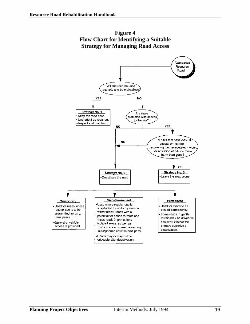
Identifying Access Management Strategy
Identify a suitable strategy for managing road access. There are three possiblestrategies (see Figure 4):
Resource Road Rehabilitation Handbook
Planning Project Objectives Interim Methods: July 1994 14
• Strategy 1: Leave the road open for regular use, upgrade it to currentstandards if necessary, then inspect and maintain it. The road is called a“maintained road.” You must name the agency or organizationresponsible for inspections and maintenance.
• Strategy 2: Deactivate the road to a temporary, semi-permanent, orpermanent level, based on the term and type of access desired and onsilviculture objectives.
• Strategy 3: For sites that have very difficult access or that are partlyrecovering (i.e., revegetated), leave the road alone if site works could domore harm than good.
Document the recommended strategy for each road directly on the roadinventory base maps, map overlays, or tabulated lists, whichever is mostappropriate for field use.
You will probably need to reassess recommended strategies for managingaccess as field assessments proceed—strategies can change based on fieldevaluations of the severity of road problems and the sensitivity of the terrain.For example, you originally target a road for “semi-permanent deactivation”and four wheel drive access. Later you find that this road cannot bemaintained because of stability considerations or because no agency ororganization will commit to maintaining it. In this case, you should revise theaccess management strategy to “permanent deactivation” and prescribetreatments consistent with the new strategy.
Here are detailed descriptions of the requirements for each strategy.
Strategy 1: Inspect and Maintain Roads and Bridges
• If you decide to reinstate regular inspection and maintenance operationson abandoned road systems, clearly name the agency or organization thatis responsible for the inspection and maintenance.
• The named agency or organization should carry out corrective action onthese road systems as soon as possible to address any identified erosionand slope stability hazards.
• Abandoned roads could be maintained under the requirements of RoadUse Permits, Road Permits, Cutting Permits, Special Use Permits, or othertenure obligations. Appendix D, Types of Resource Roads, LoggingTrails, and Permits, explains the various types of road permits.
Resource Road Rehabilitation Handbook
Planning Project Objectives Interim Methods: July 1994 15
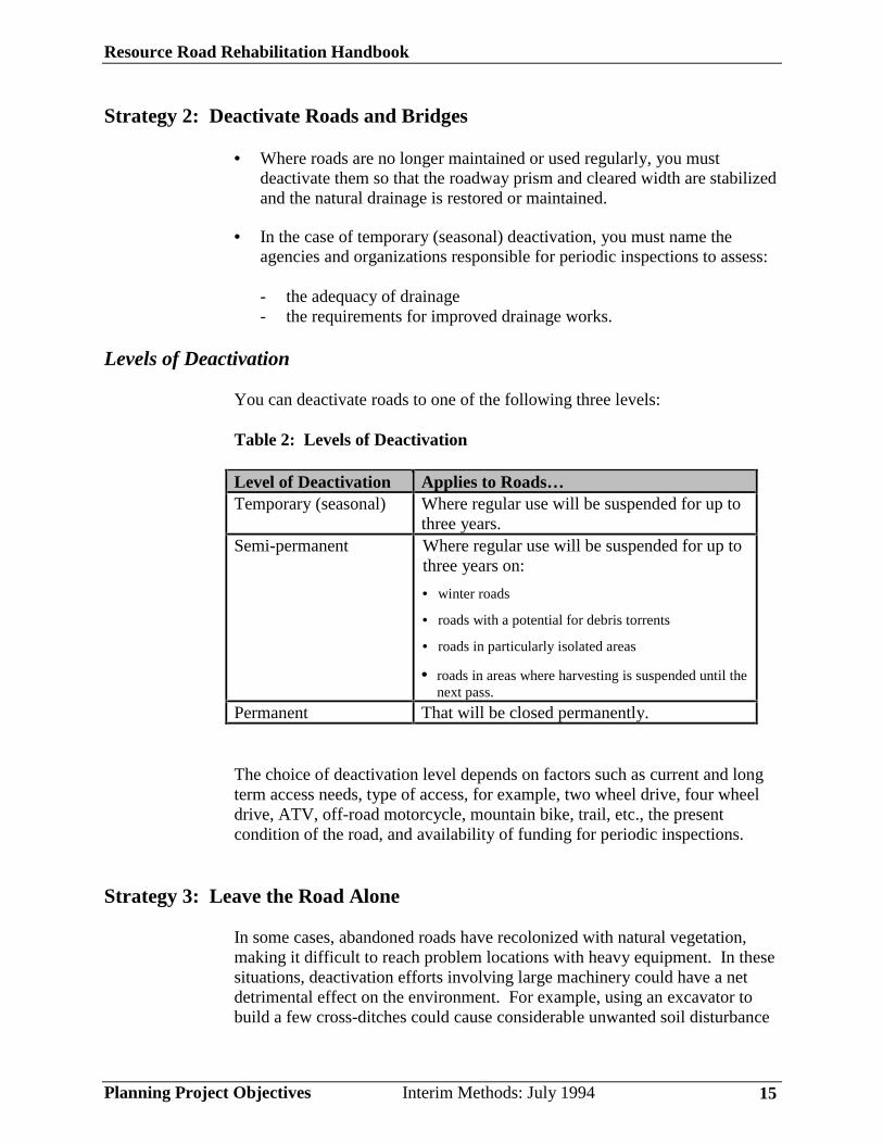
Strategy 2: Deactivate Roads and Bridges
• Where roads are no longer maintained or used regularly, you mustdeactivate them so that the roadway prism and cleared width are stabilizedand the natural drainage is restored or maintained.
• In the case of temporary (seasonal) deactivation, you must name theagencies and organizations responsible for periodic inspections to assess:
- the adequacy of drainage- the requirements for improved drainage works.
Levels of Deactivation
You can deactivate roads to one of the following three levels:
Table 2: Levels of Deactivation
Level of Deactivation Applies to Roads…Temporary (seasonal) Where regular use will be suspended for up to
three years.Semi-permanent Where regular use will be suspended for up to
three years on:
• winter roads
• roads with a potential for debris torrents
• roads in particularly isolated areas
• roads in areas where harvesting is suspended until thenext pass.
Permanent That will be closed permanently.
The choice of deactivation level depends on factors such as current and longterm access needs, type of access, for example, two wheel drive, four wheeldrive, ATV, off-road motorcycle, mountain bike, trail, etc., the presentcondition of the road, and availability of funding for periodic inspections.
Strategy 3: Leave the Road Alone
In some cases, abandoned roads have recolonized with natural vegetation,making it difficult to reach problem locations with heavy equipment. In thesesituations, deactivation efforts involving large machinery could have a netdetrimental effect on the environment. For example, using an excavator tobuild a few cross-ditches could cause considerable unwanted soil disturbance
Resource Road Rehabilitation Handbook
Planning Project Objectives Interim Methods: July 1994 16
and destruction of vegetation. However, in some cases where heavy treegrowth exists within the road prism, using excavators or explosives may bewarranted to retrieve or remove any unstable sidecast fills. Therefore, acomplete field assessment of site conditions must compare the level of sitedisturbance that carrying out remedial works using heavy equipment (or othermeans) might cause with the possible consequences of leaving the site alone.
In some situations, although culverts still remain in the road fills, the naturaldrainage system may have re-established itself. Therefore, the culverts maypose no threat of landslides or continued surface erosion; the drainagestructures can remain in place. However, where existing drainage structuresdo pose a definite risk of slope failure, remove them. For sites that areinaccessible, controlled blasting or hand labour may be appropriate methodsto remove culverts, install cross ditches and waterbars, or relieveoversteepened fillslopes.
Often, light deactivation work on difficult sites can be done by hand labour. Itis quite easy to build small cross-ditches and ditch blocks, breach old graderwindrows, and remove small culverts using a hand held or hand operated tool.In addition, carrying out small scale deactivation works by manual labour canbe cheaper than using heavy equipment. For example, 20 man-days of manuallabour might build as many cross-ditches for the same cost as bringing in anexcavator to an inaccessible location.
Defining Project Scope and Objectives for the Zone
You should clearly define the project scope and formulate a clear statement ofproject objectives for the zone of interest before you ask technicians andspecialists to conduct a Level II Field Assessment (see Figure 3). This isimportant information to the personnel who conduct such detailed assessmentsbecause it guides their selection of appropriate road rehabilitationprescriptions. Before proceeding to a Level II Field Assessment, consult withthe Ministry of Forests to obtain its comments or suggestions concerning theproject scope and statement of objectives.
Scope of the Rehabilitation Project
In many situations, abandoned road networks provide access to landslidetracks and gullies, and cutblocks (including logging trails and fireguards) thatneed remedial works. Often, these hillslope components can only be treatedcost effectively when the road network remain open. It is important to decidehow and when to schedule Level II Field Assessments and rehabilitation siteworks for these other hillslope components.
Resource Road Rehabilitation Handbook
Planning Project Objectives Interim Methods: July 1994 17
Plan to make effective use of specialists, technicians, and equipment, whilethey are on site within the zone of interest. Typically, Level II FieldAssessments for road deactivation projects also include examinations of, andprescriptions for, gullies and landslide tracks located along the road corridor.It may be appropriate to schedule Level II Field Assessments for clearcuts(including logging trails and fireguards) separately if they require theinvolvement and input of specialists with backgrounds other than resourceroad engineering, such as silviculturalists and soil scientists. Also, askyourself the following question: Could the proposed road deactivation isolateuntreated sites outside the zone, such as roads (including landings), gullies,landslide tracks, pits and quarries, and clearcuts (including logging trails andfireguards)? If so, expand the zone of interest to include these other sites.
You should specify what is and what is not part of the Level II FieldAssessment. Examples: “silviculture site treatments are not part of the fieldwork,” or “prescriptions for gullies and landslide tracks are included in thescope of field work,” or “clearcuts (including logging trails and fireguards)are not included in the scope of the field work,” etc. Make reference to theroad names or numbers on the inventory base maps to accurately delineate thescope of the work.
Objectives of the Road Rehabilitation Project
To define complete project objectives for the zone, you should consider therisk to timber and non-timber values, the strategies for managing access, theroad conditions, and other important factors. For example, consider thefollowing factors in setting the rehabilitation project objectives for the LevelII Field Assessment:
• the overall condition of the road network, including the integrity andcapability of its drainage structures, and the likelihood of potential slopestability and surface erosion problems
• the need to protect human life, and property, if threatened
• the need to protect water quality, water supply, fish habitat, visualaesthetics, and site productivity and timber resources, if threatened
• the requirements for current and future road access, including access needsfor timber development, other forest management, commercial andrecreational uses, and other WRP Projects. You should review therequirements of existing Access Management Plans, Management Plansand Forest Development Plans for an area.

Resource Road Rehabilitation Handbook
Planning Project Objectives Interim Methods: July 1994 18
• the requirements for silviculture enhancement (new growing sites)
• the requirements for long-term road inspections and maintenance
• the rainfall regime, climate, snowmelt, and runoff intensities
• other factors
A statement of objectives should include:
• a general description of the zone
• the intent of the road rehabilitation project. For example: “reduce the riskof slope failure and surface soil erosion that could have an impact on highvalue fisheries and community water supply”
• the primary concerns that have initiated the project. For example:potential road related slope stability problems, potential erosion ofexposed mineral soils across landslide tracks, potential for torrenting ofgullies, need for erosion control and water management, etc.
• the recommended access strategy for each road, clearly referenced to theinventory base maps.
Resource Road Rehabilitation Handbook
Planning Project Objectives Interim Methods: July 1994 19
Figure 4 Flow Chart for Identifying a Suitable Strategy for Managing Road Access

Resource Road Rehabilitation Handbook
Conducting Field Assessments Interim Methods: July 1994 20
Step 2: Conducting Field AssessmentsThere are two levels of field assessments (see Figure 3):
• During a Level I Field Assessment, you conduct an overviewexamination of the road network and related structures. This level of fieldassessment is required only if more information is needed to completeStep 1 tasks.
• During a Level II Field Assessment, you conduct a more detailedexamination and prescribe treatments. This level of field assessment isconducted after completing Step 1 tasks; it is mandatory for all roadrehabilitation projects.
This section describes the two levels of field assessments as well as therecommended qualifications for field inspection staff.
Recommended Qualifications of Field Inspection Staff
Recognized, qualified professionals and technicians who possess ademonstrated ability and understanding in applying of sound resource roadengineering practices should conduct field inspections of roads. Ideally, theseindividuals should have the following knowledge and skills:
• a thorough understanding of terrain and landslide processes and foresthydrology
• a thorough understanding of road reconstruction, maintenance, anddeactivation practices.
• an ability to recognize field indicators of active or potential road-relatedproblems.
• an ability to make rational recommendations for remedial action
• the common sense to know when to seek the assistance of specialists.
Specialists
Field staff must consult specialists when solutions to complex road problemsrequire expert advice, and when these problems are perceived or identified tobe a threat to human life, private property, highways, railways, or publicutilities. Specialists include B.C. registered Professional Engineers,Geoscientists, and others with relevant training and experience. If the
Resource Road Rehabilitation Handbook
Conducting Field Assessments Interim Methods: July 1994 21
problem site has prevailed for some time, you will probably also require theextensive help of specialists in road and slope stability, hydrology andrevegetation during the field assessment stage and when laying out the workin the field.
In some cases, the specialist must also prepare a prescription for deactivationwork. The May 1994 version of the British Columbia Forest Practices Code(Draft) Standards, Section 9.9(5) states the following:
Prescriptions for deactivation work must be submitted and approvedbefore work begins. A professional engineer or professional geoscientistmust prepare a prescription for deactivation work in areas that may beprone to mass wasting and, where so specified in the prescription, mustcertify that the deactivation work was carried out in conformance to theprescription.
Level I Field Assessment
Conduct a Level I Field Assessment if you need more field information tocomplete the tasks in Step 1 (see Figure 3). The field work carried out under aLevel I program can be designed to obtain an overview level of informationfor a variety of purposes:
• Level I Field information helps confirm the priorities of zones for roadinventory mapping and Level II Field Assessments identified in Step 1.
• In some areas of the province, information on the condition of abandonedforest roads is limited. For example, often no local knowledge about thecondition of roads exists, despite aerial photograph coverage. A Level IField Assessment can provide additional information to help you identifynew high priority zones for planning road inventory mapping and Level IIField Assessments.
• Level I field information can help establish the best strategy for managingaccess in a particular zone.
• Level I field information can be useful in preparing preliminary budgetsand schedules, and to better define the rehabilitation project scope andobjectives for future Level II Field Assessments and site works.
Important: Level I Field Assessments are not suitable for prescribingtreatments. Only Level II Field Assessments are suitable for such purposes.
Resource Road Rehabilitation Handbook
Conducting Field Assessments Interim Methods: July 1994 22
The types of activities carried out for a Level I Field Assessment will dependon what information you need to complete Step 1 tasks. A Level I FieldAssessment may include some or all the following activities:
• conducting overview field inspections of existing road conditions• conducting overview risk assessments• verifying road inventory base map information• preparing overview cost and time estimates.
These are explained in more detail below:
Conducting Overview Field Inspections of Existing Road Conditions
You can drive, walk, or ride mountain bikes or ATV’s over the road, orvisually assess it from the air. The method you choose depends on existingaccess and the level of information desired. Where time and resources arelimited, or where information is scarce, a helicopter reconnaissance may oftenyield a cost-effective overview of site conditions. Certain downslope impactsand drainage patterns may be best detected by aerial reconnaissance.However, there are certain details you cannot examine from a helicopter, suchas blocked drainage structures, tension cracks in road subgrade, or old stumpssupporting sidecast fill. Helicopter reviews may only be valuable inidentifying high hazard road segments and erosion sites that need closerexamination on the ground.
Record the following information in your field notes or on field record forms:
1. General Information:
• geographic area• terrain hazard class• zone/watershed/map reference• road name/number• road type (main, branch, spur, block logging trail, other)• date of field inspection• assessor• weather details• licensee (if applicable)• file name• apparent use status (heavy or light vehicle use or no apparent use)• planned road management strategy• method of inspection (helicopter, drive, walk, ATV, other)
Resource Road Rehabilitation Handbook
Conducting Field Assessments Interim Methods: July 1994 23
2. Existing and potential problems identified along the road corridor,including problems with gullies and landslide tracks that must becorrected. You should record your general observations for each roadexamined. The following problems are often typical of abandoned forestroads.
• plugged ditches/no ditches• no ditchblocks• ditchwater flowing directly into streams• plugged/damaged culverts• insufficient cross-drain culverts• undersized cross-drain culverts• natural drainage blocked/diverted• ditchline/road surface erosion• unstable or eroding cut/fill slopes• washout of road/bridge• damaged/unsafe bridge• landslide tracks• tension cracks on road• fill/debris in channels• beaver dams• cattle usage• organic material & stumps supporting sidecast fill
Take photographs or videos and regular field notes for documentationpurposes. Photographs or videos taken from a helicopter are invaluable forshowing an overview of the actual site conditions for later review andanalysis.
Appendix F provides examples of road inspection forms that may be usefulfor recording field data obtained during a Level 1 Field Assessment. Youshould develop your own field record forms to meet your specific needs. Besure to use a data format that can be readily entered into a computer data base.
Important: Alert all appropriate agencies immediately if there is a perceivedor identified threat to onsite, upslope, or downslope areas along road corridorsthat contain rural development, domestic dwellings or industrial development,highways, railways, public utilities, water supplies or fisheries habitat.
Resource Road Rehabilitation Handbook
Conducting Field Assessments Interim Methods: July 1994 24
Conducting Overview Risk Assessments
Record inventories of existing and potential hazards, such as surface soilerosion, landslides, and stream sedimentation. Assess the level of risk to theenvironment and to social and economic values by considering the factorslisted in Table 3. Use the following rating system:
• Very High (VH)• High (H)• Moderate (M)• Low (L)
For additional information on assessing risk, refer to Appendix E, RiskAssessment Procedure. Also make a preliminary judgment about how quicklythe problems, must be corrected. Based on the guidelines in Table 4,prioritize the work sequence for the zone as:
• High (H)• Medium (M)• Low (L)• No Work necessary (N)
Verifying Road Inventory Base Map Information
At the time of overview field inspections, verify and augument road inventorymap information, as required.
Preparing Overview Cost and Time Estimates
Prepare preliminary estimates of cost, time and equipment requirements basedon an overview assessment of the likely treatments required to correctproblems.
Resource Road Rehabilitation Handbook
Conducting Field Assessments Interim Methods: July 1994 25
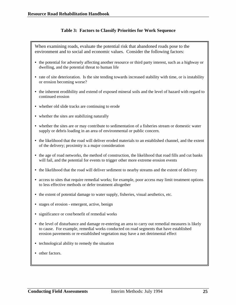
Table 3: Factors to Classify Priorities for Work Sequence
When examining roads, evaluate the potential risk that abandoned roads pose to theenvironment and to social and economic values. Consider the following factors:
• the potential for adversely affecting another resource or third party interest, such as a highway ordwelling, and the potential threat to human life
• rate of site deterioration. Is the site tending towards increased stability with time, or is instabilityor erosion becoming worse?
• the inherent erodibility and extend of exposed mineral soils and the level of hazard with regard tocontinued erosion
• whether old slide tracks are continuing to erode
• whether the sites are stabilizing naturally
• whether the sites are or may contribute to sedimentation of a fisheries stream or domestic watersupply or debris loading in an area of environmental or public concern.
• the likelihood that the road will deliver eroded materials to an established channel, and the extentof the delivery; proximity is a major consideration
• the age of road networks, the method of construction, the likelihood that road fills and cut bankswill fail, and the potential for events to trigger other more extreme erosion events
• the likelihood that the road will deliver sediment to nearby streams and the extent of delivery
• access to sites that require remedial works; for example, poor access may limit treatment optionsto less effective methods or defer treatment altogether
• the extent of potential damage to water supply, fisheries, visual aesthetics, etc.
• stages of erosion - emergent, active, benign
• significance or cost/benefit of remedial works
• the level of disturbance and damage re-entering an area to carry out remedial measures is likelyto cause. For example, remedial works conducted on road segments that have establishederosion pavements or re-established vegetation may have a net detrimental effect
• technological ability to remedy the situation
• other factors.
Resource Road Rehabilitation Handbook
Conducting Field Assessments Interim Methods: July 1994 26
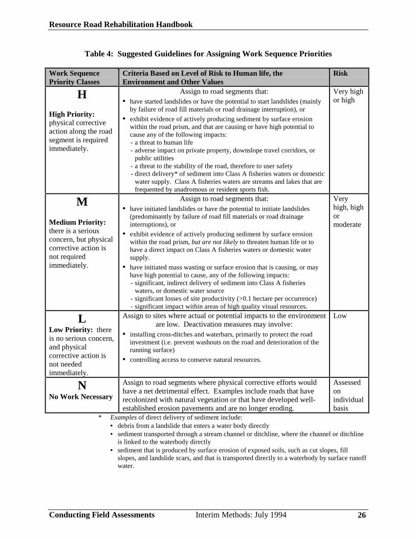
Table 4: Suggested Guidelines for Assigning Work Sequence Priorities
Work SequencePriority Classes
Criteria Based on Level of Risk to Human life, theEnvironment and Other Values
Risk
H
High Priority:physical correctiveaction along the roadsegment is requiredimmediately.
Assign to road segments that:• have started landslides or have the potential to start landslides (mainly
by failure of road fill materials or road drainage interruption), or
• exhibit evidence of actively producing sediment by surface erosionwithin the road prism, and that are causing or have high potential tocause any of the following impacts:- a threat to human life- adverse impact on private property, downslope travel corridors, or
public utilities- a threat to the stability of the road, therefore to user safety- direct delivery* of sediment into Class A fisheries waters or domestic
water supply. Class A fisheries waters are streams and lakes that arefrequented by anadromous or resident sports fish.
Very highor high
M
Medium Priority:there is a seriousconcern, but physicalcorrective action isnot requiredimmediately.
Assign to road segments that:• have initiated landslides or have the potential to initiate landslides
(predominantly by failure of road fill materials or road drainageinterruptions), or
• exhibit evidence of actively producing sediment by surface erosionwithin the road prism, but are not likely to threaten human life or tohave a direct impact on Class A fisheries waters or domestic watersupply.
• have initiated mass wasting or surface erosion that is causing, or mayhave high potential to cause, any of the following impacts:- significant, indirect delivery of sediment into Class A fisheries
waters, or domestic water source- significant losses of site productivity (>0.1 hectare per occurrence)- significant impact within areas of high quality visual resources.
Veryhigh, highormoderate
LLow Priority: thereis no serious concern,and physicalcorrective action isnot neededimmediately.
Assign to sites where actual or potential impacts to the environmentare low. Deactivation measures may involve:
• installing cross-ditches and waterbars, primarily to protect the roadinvestment (i.e. prevent washouts on the road and deterioration of therunning surface)
• controlling access to conserve natural resources.
Low
NNo Work Necessary
Assign to road segments where physical corrective efforts wouldhave a net detrimental effect. Examples include roads that haverecolonized with natural vegetation or that have developed well-established erosion pavements and are no longer eroding.
Assessedonindividualbasis
* Examples of direct delivery of sediment include:• debris from a landslide that enters a water body directly• sediment transported through a stream channel or ditchline, where the channel or ditchline
is linked to the waterbody directly• sediment that is produced by surface erosion of exposed soils, such as cut slopes, fill
slopes, and landslide scars, and that is transported directly to a waterbody by surface runoffwater.

Resource Road Rehabilitation Handbook
Conducting Field Assessments Interim Methods: July 1994 27
Level II Field Assessment (Mandatory)
You must conduct a Level II Field Assessment to prepare road rehabilitationprescriptions (see Figure 3).
General Guidelines
Within a zone of interest, detailed field work is normally carried out on allroad networks (including specified related developments) using a 1:5,000scale inventory map for field referencing purposes.
• Carry out field work for Level II Field Assessments using methods thatwill permit close examination of the road prism, drainage controls,bridges, structures, landings, pits and quarries, gullies, landslides, andclearcut areas (including logging trails and fireguards). Typically, in areasprone to mass wasting, you walk the roads., We do not recommendconducting inspections from a moving vehicle or from the air to prescriberemedial measures on roads.
• You must carry out ground inspections when there is no snow cover.
• Inspections carried out during rainy periods can provide invaluableinformation regarding the capability of culverts and general watermanagement along the road.
Procedure
1. Review the projects scope and objectives defined for the zone, and askyourself the following questions:
• Will prescriptions be limited to the roads, including landings, drainagecontrols, bridges, retaining walls, other civil structures, and gullies andlandslide tracks?
• Will prescriptions also cover pits and quarries, and clearcuts, includinglogging trails and fireguards? If not, when will inspections for thesecomponents be carried out?
The next four procedural steps assume that the inspections are limited tothe roads (including landings) and gullies and landslides located along theroad corridor.
2. Verify and augment road inventory map information, as required.
3. Accurately identify active erosion and potential problems within theroad right-of-way, and upslope and downslope, where applicable,through examinations on the ground. Assess and visually locate the

Resource Road Rehabilitation Handbook
Conducting Field Assessments Interim Methods: July 1994 28
source of problems, such as water diverted down a road, and notesediment and delivery routes. Record this information in field notes. Youcan also plot it (in the field) on 1:5,000 inventory maps, if appropriate.Assess the level of risk to the environment and to social and economicvalues by considering the factors listed in Table 3.
4. Prioritize the work sequence for sites based on the factors in Table 3
and the guidelines in Table 4.
Use the following rating system:
• High (H)• Medium (M)• Low (L)• No Work necessary (N)
You will use this information later to establish project schedules (see Step3: Preparing Reports and Maps).
To help assign priorities, assess the stage of the erosion process. Forexample, controlling or preventing early stage erosion on sites isconsidered more cost effective and more urgent than carrying outcorrective measures on sites that are in an advanced stage of erosion. Sitesin an advanced stage have begun natural recovery through vegetationre-colonization or have very limited potential for continued sedimentproduction and delivery. When assigning priorities to actively erodingsites, consider the magnitude of the erosion and sediment problem and theimmediacy of the impact or potential for initiating greater problems.
5. Make prescriptions. The prescription phase takes place in the field. Inthis phase, you identify and evaluate particular problems, then determine acourse of action to address them. Recommended prescriptions must beconsistent with the objectives of the rehabilitation project and theapproved strategy for managing access in the area. Write clear anddetailed prescriptions; they will be used as specifications in site workscontracts and must be complete to accurately describe what is required.Refer to Level II Field Assessment Report in Step 3: Preparing Reportsand Maps and Appendix I for formats to present prescriptions.
This task also includes laying out the work on site by flagging usingcolored ribbons, staking, painting marks, or be other suitable means.Make sure that the marking system used clearly indicates what is requiredto work crews and equipment operators. Forestry paint works best formarking prescriptions in the field. However, be aware that paint markingsmade in the field during wet weather will soon disappear. During poorweather conditions, use stakes or other methods that provide durable fieldidentification. Weathering and animals will remove colored ribbons over
Resource Road Rehabilitation Handbook
Conducting Field Assessments Interim Methods: July 1994 29
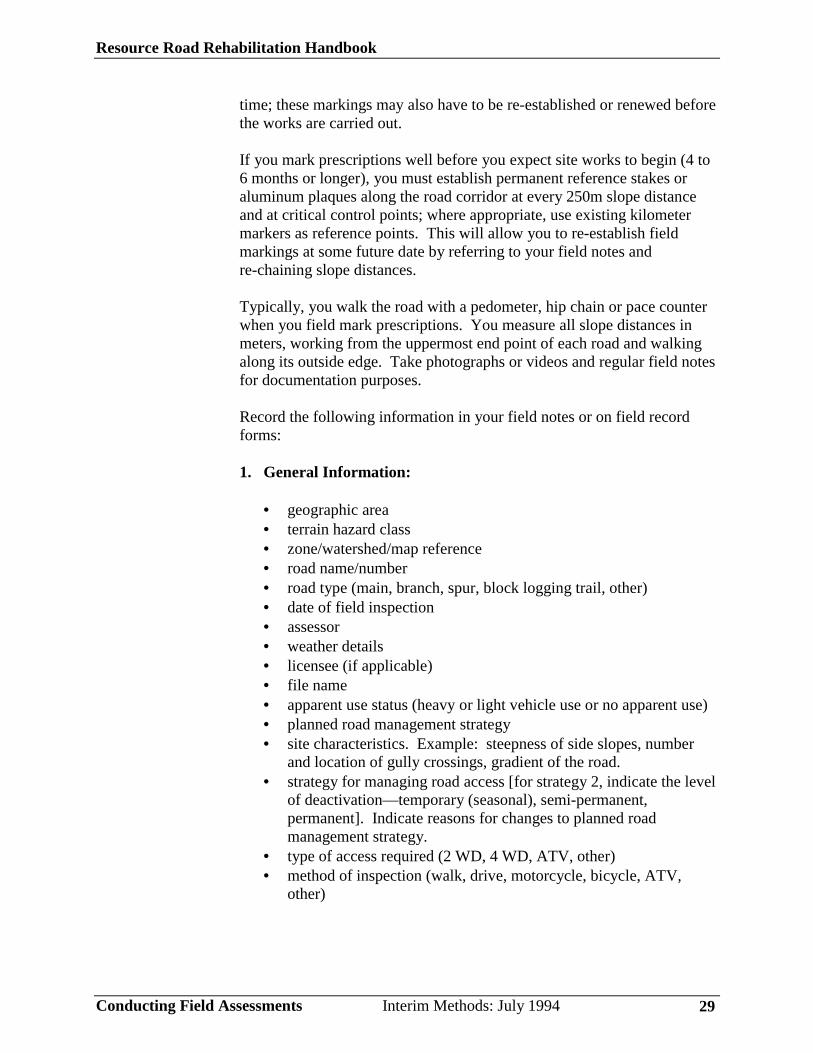
time; these markings may also have to be re-established or renewed beforethe works are carried out.
If you mark prescriptions well before you expect site works to begin (4 to6 months or longer), you must establish permanent reference stakes oraluminum plaques along the road corridor at every 250m slope distanceand at critical control points; where appropriate, use existing kilometermarkers as reference points. This will allow you to re-establish fieldmarkings at some future date by referring to your field notes andre-chaining slope distances.
Typically, you walk the road with a pedometer, hip chain or pace counterwhen you field mark prescriptions. You measure all slope distances inmeters, working from the uppermost end point of each road and walkingalong its outside edge. Take photographs or videos and regular field notesfor documentation purposes.
Record the following information in your field notes or on field recordforms:
1. General Information:
• geographic area• terrain hazard class• zone/watershed/map reference• road name/number• road type (main, branch, spur, block logging trail, other)• date of field inspection• assessor• weather details• licensee (if applicable)• file name• apparent use status (heavy or light vehicle use or no apparent use)• planned road management strategy• site characteristics. Example: steepness of side slopes, number
and location of gully crossings, gradient of the road.• strategy for managing road access [for strategy 2, indicate the level
of deactivation—temporary (seasonal), semi-permanent,permanent]. Indicate reasons for changes to planned roadmanagement strategy.
• type of access required (2 WD, 4 WD, ATV, other)• method of inspection (walk, drive, motorcycle, bicycle, ATV,
other)
Resource Road Rehabilitation Handbook
Conducting Field Assessments Interim Methods: July 1994 30
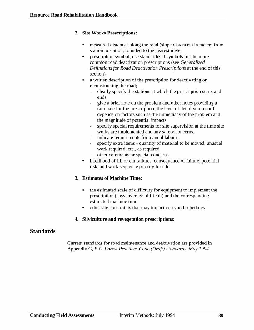
2. Site Works Prescriptions:
• measured distances along the road (slope distances) in meters fromstation to station, rounded to the nearest meter
• prescription symbol; use standardized symbols for the morecommon road deactivation prescriptions (see GeneralizedDefinitions for Road Deactivation Prescriptions at the end of thissection)
• a written description of the prescription for deactivating orreconstructing the road;- clearly specify the stations at which the prescription starts and
ends.- give a brief note on the problem and other notes providing a
rationale for the prescription; the level of detail you recorddepends on factors such as the immediacy of the problem andthe magnitude of potential impacts.
- specify special requirements for site supervision at the time siteworks are implemented and any safety concerns.
- indicate requirements for manual labour.- specify extra items - quantity of material to be moved, unusual
work required, etc., as required- other comments or special concerns
• likelihood of fill or cut failures, consequence of failure, potentialrisk, and work sequence priority for site
3. Estimates of Machine Time:
• the estimated scale of difficulty for equipment to implement theprescription (easy, average, difficult) and the correspondingestimated machine time
• other site constraints that may impact costs and schedules
4. Silviculture and revegetation prescriptions:
Standards
Current standards for road maintenance and deactivation are provided inAppendix G, B.C. Forest Practices Code (Draft) Standards, May 1994.
Resource Road Rehabilitation Handbook
Conducting Field Assessments Interim Methods: July 1994 31
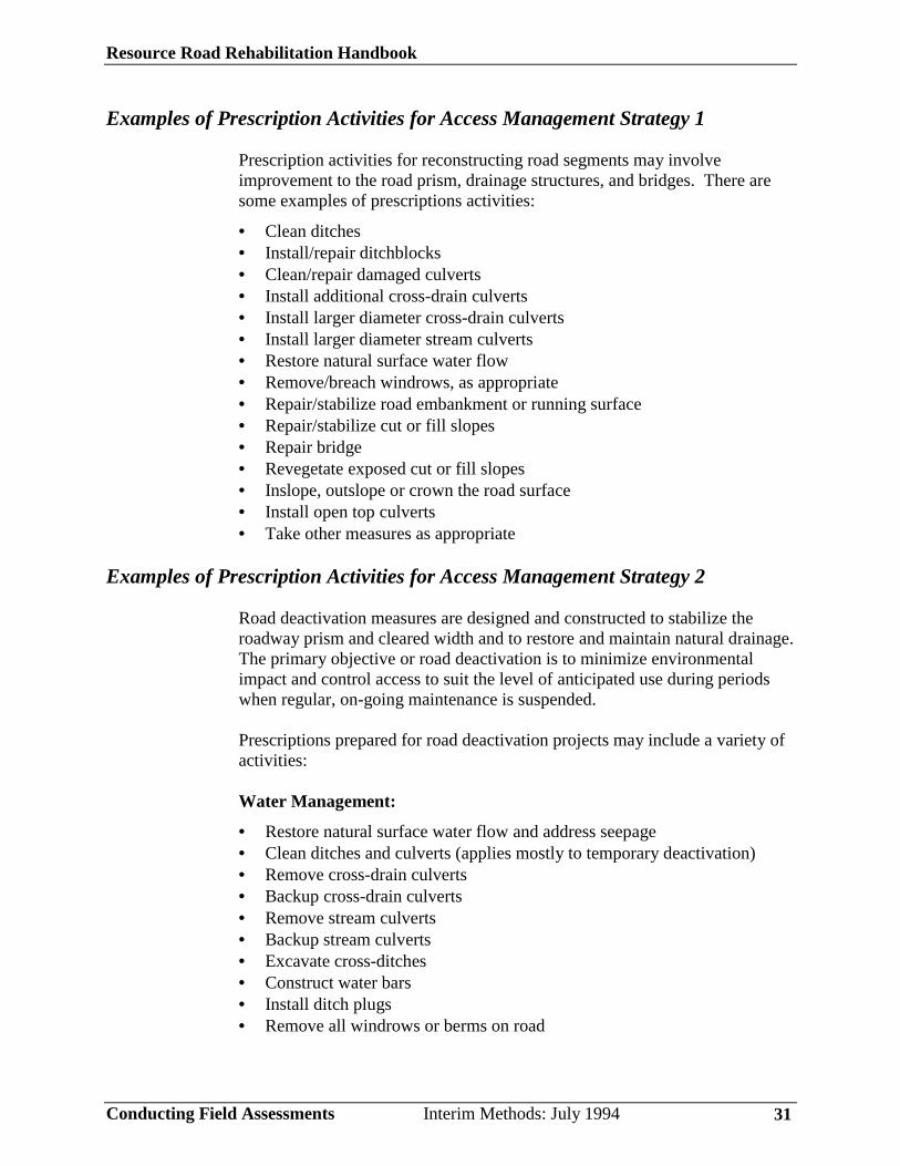
Examples of Prescription Activities for Access Management Strategy 1
Prescription activities for reconstructing road segments may involveimprovement to the road prism, drainage structures, and bridges. There aresome examples of prescriptions activities:
• Clean ditches• Install/repair ditchblocks• Clean/repair damaged culverts• Install additional cross-drain culverts• Install larger diameter cross-drain culverts• Install larger diameter stream culverts• Restore natural surface water flow• Remove/breach windrows, as appropriate• Repair/stabilize road embankment or running surface• Repair/stabilize cut or fill slopes• Repair bridge• Revegetate exposed cut or fill slopes• Inslope, outslope or crown the road surface• Install open top culverts• Take other measures as appropriate
Examples of Prescription Activities for Access Management Strategy 2
Road deactivation measures are designed and constructed to stabilize theroadway prism and cleared width and to restore and maintain natural drainage.The primary objective or road deactivation is to minimize environmentalimpact and control access to suit the level of anticipated use during periodswhen regular, on-going maintenance is suspended.
Prescriptions prepared for road deactivation projects may include a variety ofactivities:
Water Management:
• Restore natural surface water flow and address seepage• Clean ditches and culverts (applies mostly to temporary deactivation)• Remove cross-drain culverts• Backup cross-drain culverts• Remove stream culverts• Backup stream culverts• Excavate cross-ditches• Construct water bars• Install ditch plugs• Remove all windrows or berms on road
Resource Road Rehabilitation Handbook
Conducting Field Assessments Interim Methods: July 1994 32
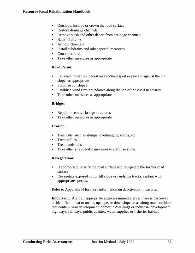
• Outslope, inslope or crown the road surface• Restore drainage channels• Remove slash and other debris from drainage channels• Backfill ditches• Armour channels• Install subdrains and other special measures• Construct fords• Take other measures as appropriate
Road Prism:
• Excavate unstable sidecast and endhaul spoil or place it against the cutslope, as appropriate
• Stabilize cut slopes• Establish wind firm boundaries along the top of the cut if necessary• Take other measures as appropriate
Bridges:
• Repair or remove bridge structures• Take other measures as appropriate
Erosion:
• Treat cuts, such as slumps, overhanging scarps, etc.• Treat gullies• Treat landslides• Take other site specific measures to stabilize slides
Revegetation:
• If appropriate, scarify the road surface and revegetate the former roadsurface
• Revegetate exposed cut or fill slope or landslide tracks; replant withappropriate species.
Refer to Appendix H for more information on deactivation measures.
Important: Alert all appropriate agencies immediately if there is perceivedor identified threat to onsite, upslope, or downslope areas along road corridorsthat contain rural development, domestic dwellings or industrial development,highways, railways, public utilities, water supplies or fisheries habitat.
Resource Road Rehabilitation Handbook
Conducting Field Assessments Interim Methods: July 1994 33
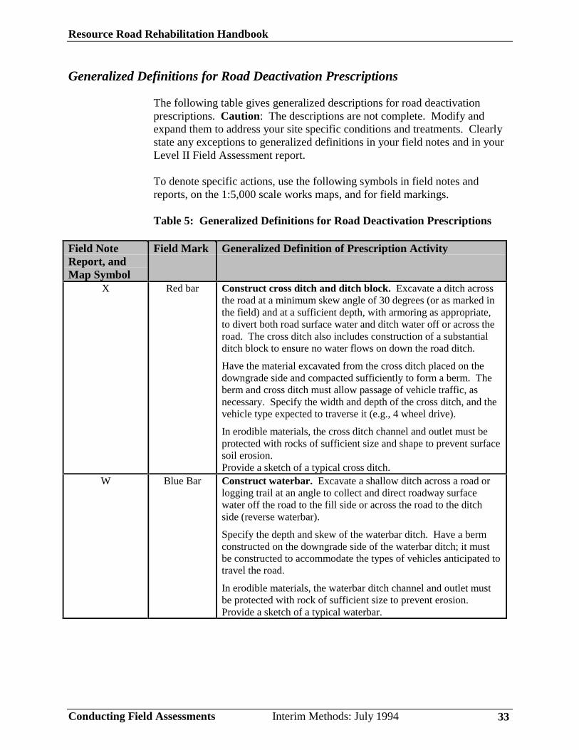
Generalized Definitions for Road Deactivation Prescriptions
The following table gives generalized descriptions for road deactivationprescriptions. Caution: The descriptions are not complete. Modify andexpand them to address your site specific conditions and treatments. Clearlystate any exceptions to generalized definitions in your field notes and in yourLevel II Field Assessment report.
To denote specific actions, use the following symbols in field notes andreports, on the 1:5,000 scale works maps, and for field markings.
Table 5: Generalized Definitions for Road Deactivation Prescriptions
Field NoteReport, andMap Symbol
Field Mark Generalized Definition of Prescription Activity
X Red bar Construct cross ditch and ditch block. Excavate a ditch acrossthe road at a minimum skew angle of 30 degrees (or as marked inthe field) and at a sufficient depth, with armoring as appropriate,to divert both road surface water and ditch water off or across theroad. The cross ditch also includes construction of a substantialditch block to ensure no water flows on down the road ditch.
Have the material excavated from the cross ditch placed on thedowngrade side and compacted sufficiently to form a berm. Theberm and cross ditch must allow passage of vehicle traffic, asnecessary. Specify the width and depth of the cross ditch, and thevehicle type expected to traverse it (e.g., 4 wheel drive).
In erodible materials, the cross ditch channel and outlet must beprotected with rocks of sufficient size and shape to prevent surfacesoil erosion.Provide a sketch of a typical cross ditch.
W Blue Bar Construct waterbar. Excavate a shallow ditch across a road orlogging trail at an angle to collect and direct roadway surfacewater off the road to the fill side or across the road to the ditchside (reverse waterbar).
Specify the depth and skew of the waterbar ditch. Have a bermconstructed on the downgrade side of the waterbar ditch; it mustbe constructed to accommodate the types of vehicles anticipated totravel the road.
In erodible materials, the waterbar ditch channel and outlet mustbe protected with rock of sufficient size to prevent erosion.Provide a sketch of a typical waterbar.

Resource Road Rehabilitation Handbook
Conducting Field Assessments Interim Methods: July 1994 34
Field NoteReport, andMap Symbol
Field Mark Generalized Definition of Prescription Activity
F F Construct ford. Construct a dip in the roadbed at a streamcrossing, instead of a culvert or bridge. The streambed must beerosion-resistant material, or such material must be placed incontact with the streambed. Specify construction details,including erosion protection, and types of vehicles expected totravel over it.
CC CC Clean or repair culvert (for maintenance purposes or temporarydeactivation).
RWC RWC Remove wood culvert and build cross ditch and ditch block. Itis critical to provide erosion protection at the outlet.
RMC RMC Remove metal culvert and build cross ditch and ditch block. Itis critical to provide erosion protection at the outlet.
BWC BWC Backup wood culvert and build cross ditch on the upgradeside. It is critical to provide erosion protection at the outlet.
BMC BMC Backup metal culvert and build cross ditch on the upgradeside. It is critical to provide erosion protection at the outlet.
RW RW Remove windrow. Remove accumulated pile of road fill orsurfacing material left on the road shoulder by graders.
RB RB Remove bridge. Specify components to remove, disposal ofmaterials, window for work, and construction detail for ford.
PFH Pink Stripe Pull back sidecast fill (heavy). For stability reasons, retrievesidecast fill materials. All material reached by full extension ofthe excavator bucket should be removed.
The fill retrieved should be placed tightly against the inside of theroadway and contoured to recreate natural cross slope topography.The roadway ditch must be filled and made inoperable. Old roadsurface should slope slightly outward. There should be no areasleft that will allow water to accumulate along the former roadsurface.
The old ditch should not trap or direct ground water. Make sureyou leave no windrow or spoil.Specify the width of the pullback and approximate depth ofexcavation at the road shoulder.
PFM 2OrangeStripes
Pullback sidecast fill (moderate). For stability reasons, retrievesidecast fill materials. Description is between light and heavy.Specify the width of the pullback and approximate depth ofexcavation at the road shoulder.
PFL 1YellowStripe
Pullback sidecast fill (light). For stability reasons, retrievesidecast fill materials. Specify the width of the pullback andapproximate depth of excavation at the road shoulder.

Resource Road Rehabilitation Handbook
Conducting Field Assessments Interim Methods: July 1994 35
Field NoteReport, andMap Symbol
Field Mark Generalized Definition of Prescription Activity
H H Leave heli-pad site. Site must be flat with clear approaches.Knock down any projections. Specify dimensions based onTransport Canada’s recommendations.
PL PL Pullback landing. Specify requirements in design notes.PWD PWD Pullback woody debris. Pull woody debris off slope and pile on
adjacent road or nearby flat area. Typically required to preventwater course damage or plugging if this material moves intochannel.
PO PO Pull down overhang cut.PS PS Pullback for silviculture purposes.SR SR Scarify the road surface.OS OS Outslope the road surface. For water management reasons.
Specify cross slope.IS IS Inslope the road surface. For water management reasons.
Specify cross slope.EH EH End haul excavation waste materials. Specify end haul spoil
site.Use a symbol
other than onesused above.
Use a symbolother than ones
used above.
Take other measures as required (define the prescription activity).
Resource Road Rehabilitation Handbook
Preparing Reports and Maps Interim Methods: July 1994 36
Step 3: Preparing Reports and Maps
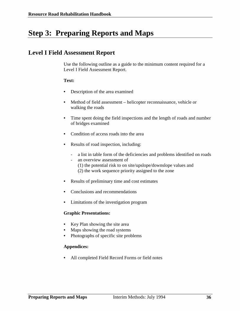
Level I Field Assessment Report
Use the following outline as a guide to the minimum content required for aLevel I Field Assessment Report.
Text:
• Description of the area examined
• Method of field assessment – helicopter reconnaissance, vehicle orwalking the roads
• Time spent doing the field inspections and the length of roads and numberof bridges examined
• Condition of access roads into the area
• Results of road inspection, including:
- a list in table form of the deficiencies and problems identified on roads- an overview assessment of
(1) the potential risk to on site/upslope/downslope values and(2) the work sequence priority assigned to the zone
• Results of preliminary time and cost estimates
• Conclusions and recommendations
• Limitations of the investigation program
Graphic Presentations:
• Key Plan showing the site area• Maps showing the road systems• Photographs of specific site problems
Appendices:
• All completed Field Record Forms or field notes
Resource Road Rehabilitation Handbook
Preparing Reports and Maps Interim Methods: July 1994 37
Level II Field Assessment Report
Appendix I gives examples of road deactivation reports and maps. A roadrehabilitation report should include the following information:
1. Introduction. Describe:
• the area and general geology, terrain, and hydrological environment• general condition of the roads and sites assessed• overall severity of problems encountered, and condition of access
roads into area• field observations and special concerns
2. Objectives of the rehabilitation project. Describe the purpose of theLevel II Field Assessment and the specific concerns to be addressed in thesite assessment.
3. Field work procedures. Describe:
• field work done• methods used to identify prescriptions in the field• dates of the site visits• weather details• personnel who carried out the prescriptions and those who may have
helped.
4. Definitions of symbols used for marking prescriptions in the field anddenoting specific actions on maps.
5. A summary, in spread sheet form, of the details of the work on astation by station or site specific basis. It must be concise, and directedtoward a machine operator. Include the following information:
Resource Road Rehabilitation Handbook
Preparing Reports and Maps Interim Methods: July 1994 38
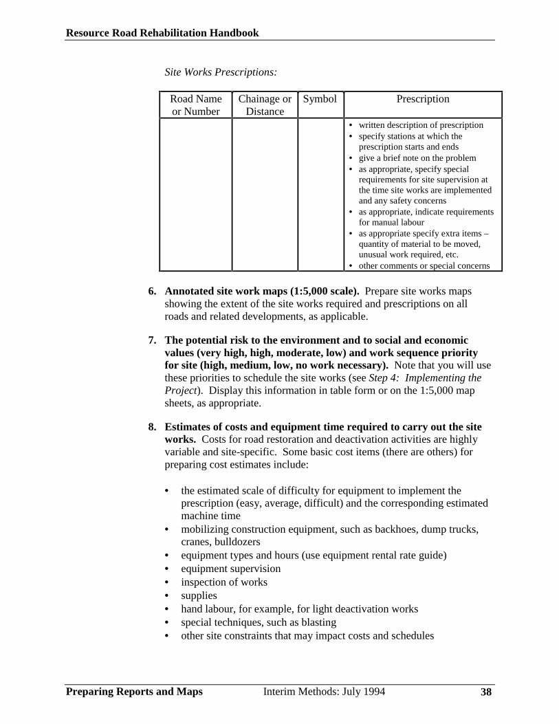
Site Works Prescriptions:
Road Nameor Number
Chainage orDistance
Symbol Prescription
• written description of prescription• specify stations at which the
prescription starts and ends• give a brief note on the problem• as appropriate, specify special
requirements for site supervision atthe time site works are implementedand any safety concerns
• as appropriate, indicate requirementsfor manual labour
• as appropriate specify extra items –quantity of material to be moved,unusual work required, etc.
• other comments or special concerns
6. Annotated site work maps (1:5,000 scale). Prepare site works mapsshowing the extent of the site works required and prescriptions on allroads and related developments, as applicable.
7. The potential risk to the environment and to social and economicvalues (very high, high, moderate, low) and work sequence priorityfor site (high, medium, low, no work necessary). Note that you will usethese priorities to schedule the site works (see Step 4: Implementing theProject). Display this information in table form or on the 1:5,000 mapsheets, as appropriate.
8. Estimates of costs and equipment time required to carry out the siteworks. Costs for road restoration and deactivation activities are highlyvariable and site-specific. Some basic cost items (there are others) forpreparing cost estimates include:
• the estimated scale of difficulty for equipment to implement theprescription (easy, average, difficult) and the corresponding estimatedmachine time
• mobilizing construction equipment, such as backhoes, dump trucks,cranes, bulldozers
• equipment types and hours (use equipment rental rate guide)• equipment supervision• inspection of works• supplies• hand labour, for example, for light deactivation works• special techniques, such as blasting• other site constraints that may impact costs and schedules
Resource Road Rehabilitation Handbook
Preparing Reports and Maps Interim Methods: July 1994 39
Make recommendations for timing of the site works.
9. Revegetation recommendations. Clearly state the objectives ofrevegetation work for each site, such as erosion and siltation control,visual cover, or maintaining productive tree growth. The choice oftechnique is critical to ensure successful, cost effective results. Seek theadvice of an erosion control specialist, forester or silviculturist, asappropriate.
In your recommendations, specify the following:
• objectives• type of revegetation (seeding, planting)• method of application (dry seeding, hydroseeding)• equipment (hand seeders, truck based, helicopter)• timing (season, dates, sequence of multi-stage operations)• seeding materials and rates (seed mix, fertilizer types if suitable for the
site, mulch, tackifier)• planting materials and density (species, seedling stock type, cuttings)• bioengineering techniques, if applicable• cost estimate• site preparation and access requirements to facilitate revegetation).
10. Site supervision requirements. State recommendations for sitesupervision (full time, periodic); also specify the operations or work areasthat will require mandatory full time supervision during implementation ofthe site works.
11. Safety concerns. State any concern for safety during implementation ofsite works (e.g., unstable cut or fill slopes that equipment operators shouldbe aware of).
12. Recommendations for future work.
13. Appendices. Provide a copy of all completed field notes or Field RecordForms.

Resource Road Rehabilitation Handbook
Implementing the Project Interim Methods: July 1994 40
Step 4: Implementing the Project
Scheduling Implementation of Site WorksThe schedule for carrying out site works depends on:
• work sequence priorities for sites established during the field work (referto Step 2: Conducting Field Assessments)
• availability of funds• seasonal or other operational constraints• future access requirements• logistics, such as work sequences progressing from the farthest end of the
road system and access requirements and constraints• stability concerns, such as a high potential for a slide to occur at the road,
cutting off future access.
Schedules can have multi-staged plans for certain activities, such as seedingand replanting, or stabilizing major slides. In preparing a schedule, take noteof any special materials or equipment that will require special planning orprocurement in advance.
Site Works SupervisionIdeally, the individual that has made the prescriptions should work closelywith the equipment operator to review the work and to ensure that the operatorunderstands why and how certain activities are carried out. This will help theequipment operator make final adjustments in the recommended work basedon actual site conditions encountered. For example, the operator can decideexactly how much fill is pulled back in a specific place to ensure that neithertoo much or too little work is done.
The site supervisor should check off work done against the work map andspecifications. Site supervisors may have to collect the following data:
• equipment types used, rates, dates, and hours• equipment time and motion studies• labour hours and costs• deficiencies or revisions from original work map and specifications• photographs of the site before and after implementation of site works
(these can be used as a valuable learning tool for training of equipmentoperators in the techniques of road rehabilitation)
• over or under expenditures from original cost estimates and budgets• any unforeseen occurrences.
The site works supervisor should prepare a final inspection report oncompletion of the work.

Resource Road Rehabilitation Handbook
Monitoring and Evaluating Results Interim Methods: July 1994 41
Step 5: Monitoring and Evaluating Results
After site works have been implemented, monitor and evaluate the success ofthe treatment techniques employed.
• Determine whether the techniques employed have achieved the desiredobjectives.
• Check for renewed erosion or instability.• Inspect the progress of revegetation.• Determine the cost-effectiveness of prescriptions, and if their use is
justified for future projects.
Experience is invaluable for determining what does and does not work. Asuccessful watershed restoration program builds on past successes; we alsolearn from failures.
Maintain a data base of successes and failures for future reportingrequirements.
Appendix J, pages 102 to 114 of Cost-effectiveness of Erosion Control forForest Land Rehabilitation, Redwood National Park, provides some ideas onhow to predict and evaluate the cost effectiveness of erosion control.

Resource Road Rehabilitation Handbook
Additional Sources of Information Interim Methods: July 1994 42
Additional Sources of Information
Best, D. W., H. M. Kelsey, D. K. Hagans and M. J. Alpert (in press). Role offluvial hillslope erosion and road construction in the sediment budget ofGarrett Creek, Humboldt County, California. In: K. M. Noland, H. M.Kelsey and D. C. Marron (Ed), Geomorphic process and aquatic habitat inthe Redwook Creek basin, northern California, USGS Prof. Paper 1454.
British Columbia. B.C. Ministry of Transportation and Highways, and B.C.Hydro and Power Authority and B.C. Rail Ltd. (1994). Equipment RentalRate Guide. Victoria, British Columbia: B.C. Ministry of Transportationand Highways.
British Columbia Institute of Technology (1994). RRET 3310/3311 RoadConstruction Practices and Procedures, Seminar Manual (ForestEngineering Technology). Burnaby, British Columbia: B.C. Institute ofTechnology.
Gerath, R. F., O. Hungr and D. F. VanDine (1994). Landslide HazardMapping Guidelines for British Columbia. Vancouver , British Columbia:The Earth Sciences Task Force, B.C. Government Resources InventoryCommittee.
Hammond, Carol, David Hall, Stanley Miller, Paul Swetik (1992). Level IStability Analysis (LISA) Documentation for Version 2.0, GeneralTechnical Report INT-285. Ogden, UT: United States Department ofAgriculture, Forest Service, Intermountain Research Station.
Pacific Watershed Associates (1994-in press). Handbook for forest and ranchroads. California: prepared for the Mendocino County ResourceConservation District in cooperation with the California Department ofForestry and the U.S. Soil Conservation Service.
Pacific Watershed Associates (1994). Action plan for restoration of the SouthFork Trinity River watershed and its fisheries. Weaverville, California:prepared for the U.S. Bureau of Reclamation, and Trinity River TaskForce.
Pacific Watershed Associates (1993). Treatment recommendations andspecifications for road rehabilitation and road closure, Upper CampbellCreek, Six Rivers National Forest, Humboldt County California.California: prepared for USDA Forest Service, Six Rivers NationalForest, Lower Tinity Ranger District.
Resource Road Rehabilitation Handbook
Additional Sources of Information Interim Methods: July 1994 43
Ryder, J. M. and Associates (1994). Guidelines and Standards to TerrainGeology Mapping in British Columbia. Vancouver, British Columbia:Terrain Geology Task Group, Earth Science Task Force, ResourceInventory Committee.
Stathers, R. J., T. P. Rollerson and S. J. Mitchell (1994). WindthrowHandbook for British Columbia Forests. Victoria, British Columbia:B.C. Research Branch, Ministry of Forests.
Washington State. Washington Forest Practices Board (1993). BoardManual: Standard Methodology for Conducting Watershed AnalysisUnder Chapter 222-22 WAC, Version 2.0. Olympia, Washington:Washington State Department of Natural Resources.
Weaver, W. E., D. K. Hagans and H. J. Popenoe (in press). Magnitude andcause of gully erosion in the lower Redwood Creek drainage basin. In:K. M. Nolan, H. M. Kelsey and D. C. Marron (Ed.), Geomorphic processand aquatic habitat in the Redwood Creek basin, northern California,USGS Prof. Paper 1454.
Resource Road Rehabilitation Handbook
Bibliography Interim Methods: July 1994 44
Bibliography
British Columbia. B.C. Ministry of Forests and B.C. Ministry ofEnvironment, Lands and Parks (1994). British Columbia Forest PracticesCode Standards. Victoria, British Columbia: B.C. Ministry of Forestsand B.C. Ministry of Environment, Lands and Parks, 79-100.
British Columbia. B.C. Ministy of Forests (1993). Engineering Manual.Victoria, British Columbia: Timber Harvesting Branch, B.C. Ministry ofForests.
British Columbia. B.C. Ministry of Forests (1993). Forest Road and LoggingTrail Engineering Practices (Interim) and Instructions for ItsImplementation. Victoria, British Columbia: Timber Harvesting Branch,B.C. Ministry of Forests.
British Columbia. B.C. Ministry of Environment, Lands and Parks (1988). AGuide to the Hierarchical Watershed Coding System for British Columbia.Victoria, British Columbia: B.C. Ministry of Environment, Lands andParks, 1-7.
British Columbia. Forest Renewal B.C. (1994). British Columbia’s ForestRenewal Plan Working in Partner ship, Watershed Restoration Program-Program Overview and Application Package. Victoria, British Columbia:B.C. Ministry of Environment, Lands and Parks and B.C. Ministry ofForests.
British Columbia Institute of Technology (1993). Forest Road DeactivationRRET 410. Burnaby, British Columbia: B.C. Institute of Technology.
Carr, W. W. (1980). Handbook for Forest Roadside Erosion Control in B.C.Number 4, Land Management Report No. 4. Victoria, British Columbia:B.C. Ministry of Forests.
Carr, W. W. and I. Wright (1992). A Soil Erosion and Sediment ControlPlanning System for Managed Forest Land: A Case Study at ShomarCreek, Queen Charlotte Islands, Land Management Report No. 69.Victoria, British Columbia: B.C. Ministry of Forests.
Chatwin, S. C., D. E. Howes, J. W. Schwab and D. N. Swanston (1994). AGuide for Management of Landslide-Prone Terrain in the PacificNorthwest, Land Management Handbook No. 18. Victoria, BritishColumbia: B.C. Ministry of Forests.
Resource Road Rehabilitation Handbook
Bibliography Interim Methods: July 1994 45
Hammond, H. L. (1988). Soil Degradation: Costs of Rehabilitation VersusCosts of Prevention, Land Management Report No. 56. Victoria, BritishColumbia: B.C. Ministry of Forests, 227-237.
Horel, G. (1993). Planning and Implementing Site Rehabilitation and RoadDeactivation (Draft). Nanaimo, British Columbia: MacMillan BloedelLimited, Woodlands Services Division.
Krag, R. K., E. A. Sauder and G. V. Welburn (1986). A Forest EngineeringAnalysis of Landslides in Logged Areas on the Queen Charlotte Islands,British Columbia Land Management Report No. 43. Victoria, BritishColumbia: B.C. Ministry of Forests, 18-38.
Lousier, J. D. (1990). Impacts of Forest Harvesting and Regeneration onForest Sites, Land Management Report No. 67. Victoria, BritishColumbia: B.C. Ministry of Forests.
Miller, P. A. (1988). Logging Roads: Landscape Management Implicationsof Soil Disturbance and Erosion, Land Management Report No. 56.Victoria, British Columbia: B.C. Ministry of Forests, 66-73.
Ottens, J. and J. Rudd. (1977). Environmental Protection Costs in LoggingRoad Design and Construction to prevent Increased Sedimentation in theCarnation Creek Watershed. Victoria, British Columbia: Fisheries andEnvironment Canada, Canadian Forestry Service.
Rollerson, T. (1991). Watershed Rehabilitation Strategies – Draft. Burnaby,British Columbia: Forest Sciences, Vancouver Forest Region, B.C.Ministry of Forests.
Sauder, E. A., R. K. Krag and G. V. Wellburn (1987). Logging and MassWasting in the Pacific Northwest with Application to the Queen CharlotteIslands, B.C.: A Literature Review, Land Management Report No. 53.Victoria, British Columbia: B.C. Ministry of Forests.
Schwab, J. W. (1988). Mass Wasting Impacts to Forest Land: ForestManagement Implications, Queen Charlotte Timber Supply Area, LandManagement Report No. 56. Victoria, British Columbia: B.C. Ministry ofForests, 104-115.
Tripp, D.A. Nixon and R. Dunlop. (1992). The Application and Effectivenessof the Coastal Fisheries Forestry Guidelines in Selected Cut Blocks onVancouver Island. Nanaimo, British Columbia: B.C. Ministry ofEnvironment, Lands and Parks.

Resource Road Rehabilitation Handbook
Bibliography Interim Methods: July 1994 46
Tschaplinsky, P. J. (1992). Effects of Roads on Freshwater Fish Habitats andFish Production. Victoria, British Columbia: Forest Science ResearchBranch, B.C. Ministry of Forests.
Weaver, W. E. and D. K. Hagans (1990). Techniques and costs for effectiveroad closure, Technical paper #90-1, Arcata, California: PacificWatershed Associates.
Weaver, W. E. and R. A. Sonnevil (1984). Relative cost-effectiveness orerosion control for forest land rehabilitation, Redwood National Park. In:Erosion Control…Man and Nature, Proceedings of Conference XV,International Erosion Control Association, February 23 and 24, 1984,Denver, Colorado, pp. 83-115
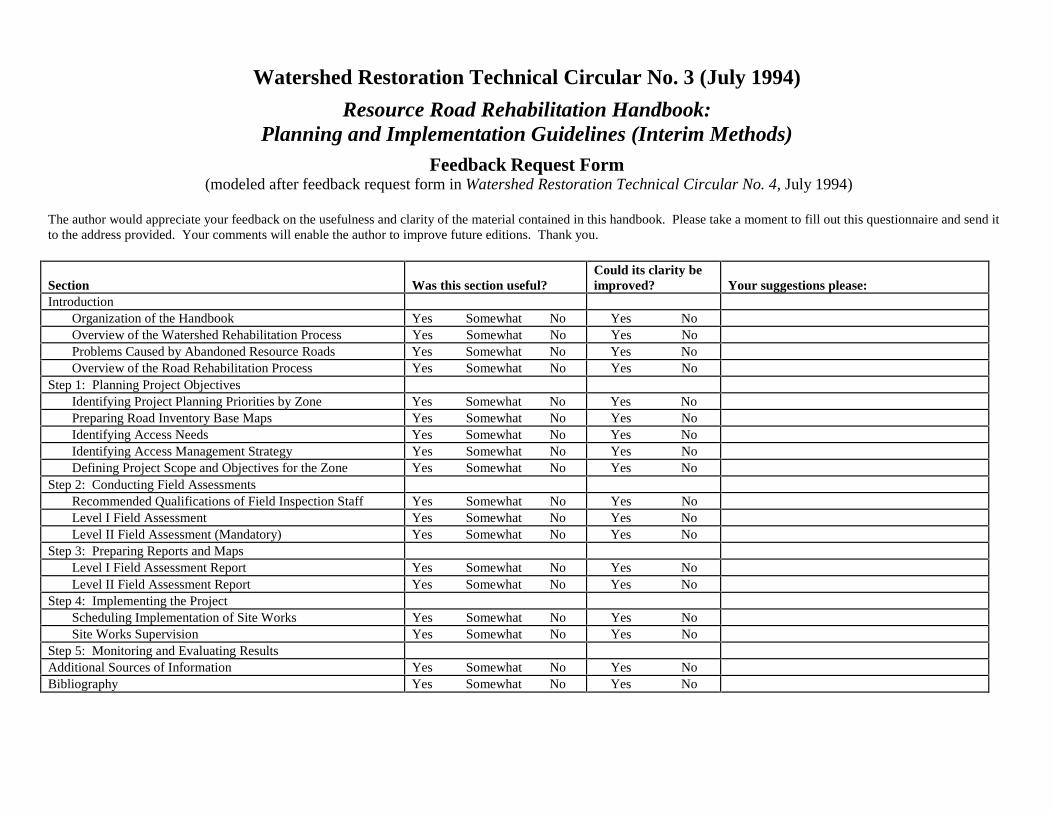
Watershed Restoration Technical Circular No. 3 (July 1994)
Resource Road Rehabilitation Handbook:Planning and Implementation Guidelines (Interim Methods)
Feedback Request Form (modeled after feedback request form in Watershed Restoration Technical Circular No. 4, July 1994)
The author would appreciate your feedback on the usefulness and clarity of the material contained in this handbook. Please take a moment to fill out this questionnaire and send itto the address provided. Your comments will enable the author to improve future editions. Thank you.
Section Was this section useful?Could its clarity beimproved? Your suggestions please:
IntroductionOrganization of the Handbook Yes Somewhat No Yes NoOverview of the Watershed Rehabilitation Process Yes Somewhat No Yes NoProblems Caused by Abandoned Resource Roads Yes Somewhat No Yes NoOverview of the Road Rehabilitation Process Yes Somewhat No Yes No
Step 1: Planning Project ObjectivesIdentifying Project Planning Priorities by Zone Yes Somewhat No Yes NoPreparing Road Inventory Base Maps Yes Somewhat No Yes NoIdentifying Access Needs Yes Somewhat No Yes NoIdentifying Access Management Strategy Yes Somewhat No Yes NoDefining Project Scope and Objectives for the Zone Yes Somewhat No Yes No
Step 2: Conducting Field AssessmentsRecommended Qualifications of Field Inspection Staff Yes Somewhat No Yes NoLevel I Field Assessment Yes Somewhat No Yes NoLevel II Field Assessment (Mandatory) Yes Somewhat No Yes No
Step 3: Preparing Reports and MapsLevel I Field Assessment Report Yes Somewhat No Yes NoLevel II Field Assessment Report Yes Somewhat No Yes No
Step 4: Implementing the ProjectScheduling Implementation of Site Works Yes Somewhat No Yes NoSite Works Supervision Yes Somewhat No Yes No
Step 5: Monitoring and Evaluating ResultsAdditional Sources of Information Yes Somewhat No Yes NoBibliography Yes Somewhat No Yes No

Section Was this section useful?Could its clarity beimproved? Your suggestions please:
Appendix A: Typical Mechanisms of Road-Associated Erosionand Sediment Production
Yes Somewhat No Yes No
Appendix B: Explanation of Some Road Deactivation Measures Yes Somewhat No Yes NoAppendix C: Effects of Roads on Freshwater Fish Habitats and
Fish ProductionYes Somewhat No Yes No
Appendix D: Types of Resource Roads, Logging Trails, &Permits
Yes Somewhat No Yes No
Appendix E: Timber Harvesting Branch “Risk AssessmentProcedure”
Yes Somewhat No Yes No
Appendix F: Miscellaneous Road Inspection Forms Yes Somewhat No Yes NoAppendix G: May 1994 Forest Practices Code Standards for
Road Maintenance and DeactivationYes Somewhat No Yes No
Appendix H: Document 1: Vancouver Forest Region, RoadConstruction , Maintenance and DeactivationHandbookDocument 2: Pacific Watersheds Associates,Techniques and costs for effective road closure
Yes Somewhat No Yes No
Appendix I: Examples of Road Deactivation Reports and Maps Yes Somewhat No Yes NoAppendix J: Relative Cost-Effectiveness of Erosion Control Yes Somewhat No Yes No
Additional Comments:

Your Occupation: _____________________________________ Please mail this form to:
The following information is optional; however, we would like to Glenn Moorehave the option to contact you and discuss your suggestions. Engineering Section
Timber Harvesting BranchYour Name: __________________________________________ B.C. Ministry of Forests
3rd Floor, 1450 Government St.Phone #: _____________________________________________ Victoria, B.C.
V8W 3E7Fax #: _______________________________________________
APPENDIX A
Typical Mechanisms of Road-AssociatedErosion and Sediment Production

Forest Roads and Slope Stability
Erosion and Sedimentation Problems
The general term ‘erosion’ refers to the detachment and transport of soil materialsfrom place to place. There are two types of erosion processes: surface soilerosion and mass wasting. Surface soil erosion is the transport of individual soilparticles primarily by the action of water, wind and frost, whereas mass wasting isthe movement of large volumes of soil or rock primarily under the influence ofgravity. Sedimentation is the deposition of eroded soil material in water.
In the natural forest environment, a thin mantle of vegetation and forest litterprotects the soil surface. This organic layer is highly porous, and because of itshigh rainfall infiltration capacity, surface runoff does not usually occur. Soilerosion is a natural process in a forested watershed but it happens at almostimperceptible rates if the forest floor remains undisturbed.
Forest road construction typically involves clearing the timber to the requiredwidth limits, grubbing and stripping at least within the running width,constructing cut and fill slopes, constructing ditches and installing culverts, andpreparing a strong subgrade to carry vehicle design wheel loads (see Figure A-1).These activities result in destruction or burial of the protective forest floor cover,and in exposure of unprotected mineral soils, and cause the rates of naturalsurface soil erosion and mass wasting to accelerate. Mass wasting, landslides,slope movements, slope failures and failures are used interchangeably throughoutthis appendix.
In the context of forest roads:
Surface Soil Erosion includes shallow erosion and gullying by running wateracross the road surface or cut and fill surfaces.
Mass Wasting includes several dominant groups of landslide processes: debrisfalls, debris slides, debris avalanches, debris flows, debris torrents, rockfalls,rockslides, slumps and earthflows, and small scale slumping, collapse, andraveling of road cuts and fills.
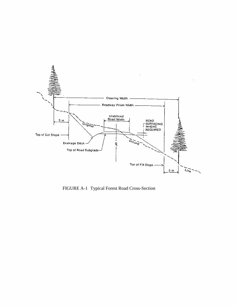
FIGURE A-1 Typical Forest Road Cross-Section
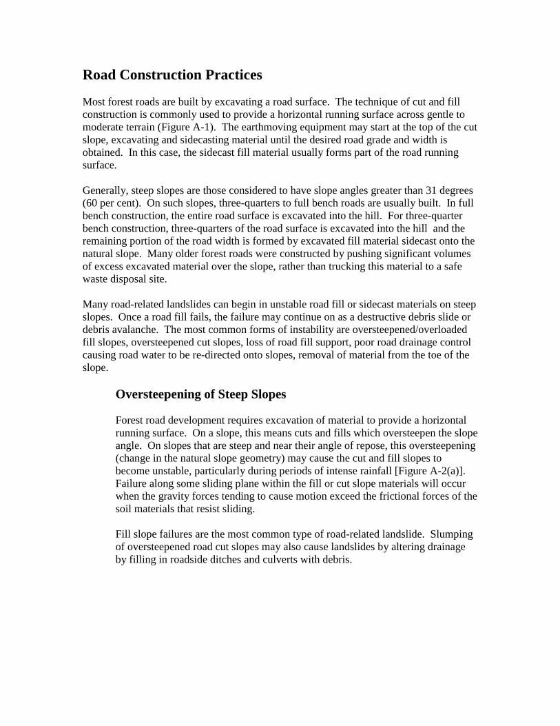
Road Construction Practices
Most forest roads are built by excavating a road surface. The technique of cut and fillconstruction is commonly used to provide a horizontal running surface across gentle tomoderate terrain (Figure A-1). The earthmoving equipment may start at the top of the cutslope, excavating and sidecasting material until the desired road grade and width isobtained. In this case, the sidecast fill material usually forms part of the road runningsurface.
Generally, steep slopes are those considered to have slope angles greater than 31 degrees(60 per cent). On such slopes, three-quarters to full bench roads are usually built. In fullbench construction, the entire road surface is excavated into the hill. For three-quarterbench construction, three-quarters of the road surface is excavated into the hill and theremaining portion of the road width is formed by excavated fill material sidecast onto thenatural slope. Many older forest roads were constructed by pushing significant volumesof excess excavated material over the slope, rather than trucking this material to a safewaste disposal site.
Many road-related landslides can begin in unstable road fill or sidecast materials on steepslopes. Once a road fill fails, the failure may continue on as a destructive debris slide ordebris avalanche. The most common forms of instability are oversteepened/overloadedfill slopes, oversteepened cut slopes, loss of road fill support, poor road drainage controlcausing road water to be re-directed onto slopes, removal of material from the toe of theslope.
Oversteepening of Steep Slopes
Forest road development requires excavation of material to provide a horizontalrunning surface. On a slope, this means cuts and fills which oversteepen the slopeangle. On slopes that are steep and near their angle of repose, this oversteepening(change in the natural slope geometry) may cause the cut and fill slopes tobecome unstable, particularly during periods of intense rainfall [Figure A-2(a)].Failure along some sliding plane within the fill or cut slope materials will occurwhen the gravity forces tending to cause motion exceed the frictional forces of thesoil materials that resist sliding.
Fill slope failures are the most common type of road-related landslide. Slumpingof oversteepened road cut slopes may also cause landslides by altering drainageby filling in roadside ditches and culverts with debris.
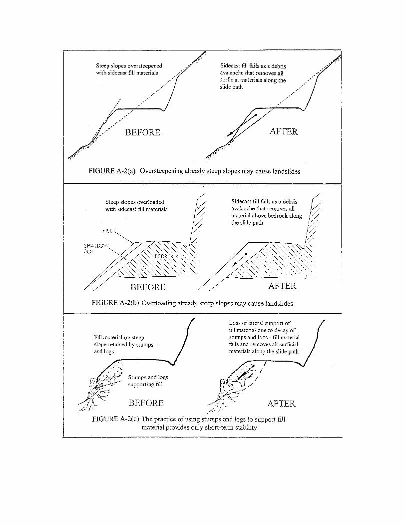
Overloading of Steep Slopes
The practice of sidecasting excavated material onto steep, sensitive natural slopescan result in overloading these slopes [Figure A-2(b)]. Most forest roads builtbefore the mid-1970’s were constructed using bulldozers or line shovels. Inbuilding roads on steep slopes, bulldozers and line shovels had limited ability tocontrol sidecast or to use excavated soil and rock to finish the roads. Such roadsbuilt on steep slopes typically involved three-quarter to full bench cuts, usually inrock. The excavated material was commonly piled loosely on the outer edge ofthe road subgrade, without end-hauling of the waste materials.
The sidecast material was commonly placed in contact with the surface of thenatural ground. As more material was sidecast, more weight was added to theslope. Since there is very little bonding of the sidecast material to the underlyingshallow topsoil and competent material, the entire slope is said to be overloaded.
Over time, and particularly during periods of heavy rainfall, the subsurface topsoilor humus layer may weaken and reduce the overall stability of the fill slope.Under these circumstances, the road fill, together with the underlying shallowtopsoil layer, may fail and form a destructive landslide.
Loss of Fill Support
As described earlier, many older forest roads were built using bulldozers and lineshovels. Such machinery had difficulty in carrying out stripping operations andsubgrade preparation in a controlled manner. By comparison, present dayhydraulic excavators are better able to strip away stumps and vegetation andseparate soil materials to produce clean, well-formed subgrades.
The limited maneuverability of machinery, and poor construction practices,resulted in many cases of older forest roads built on steep slopes by sidecastingexcavated material against large stumps, fallen logs, and ground vegetation[Figure A-2(c)]. The stability of the sidecast relied primarily on the holdingpower of the root system and vegetation. In other cases, older forest roads werebuilt on steep slopes using a retaining wall system to support the sidecast fill.This was achieved by stacking logs to form a wall on the downslope side of theroad, and tying the logs from stump to stump to resist the lateral earth pressures.Decay of the stumps, root system, and logs over the years can result in an unstableroad prism.
Lateral movements of the sidecast fill material often result in tension cracksforming along the edge of the road bed (Photo A-1). This is an indicator of anunstable road fill and that the fill may be moving downslope. Infiltration of waterinto tension cracks during heavy winter rains can trigger the road fill to failcompletely. Where roads on steep slopes exhibit such tension cracks, thepotential exists for large landslides to occur.
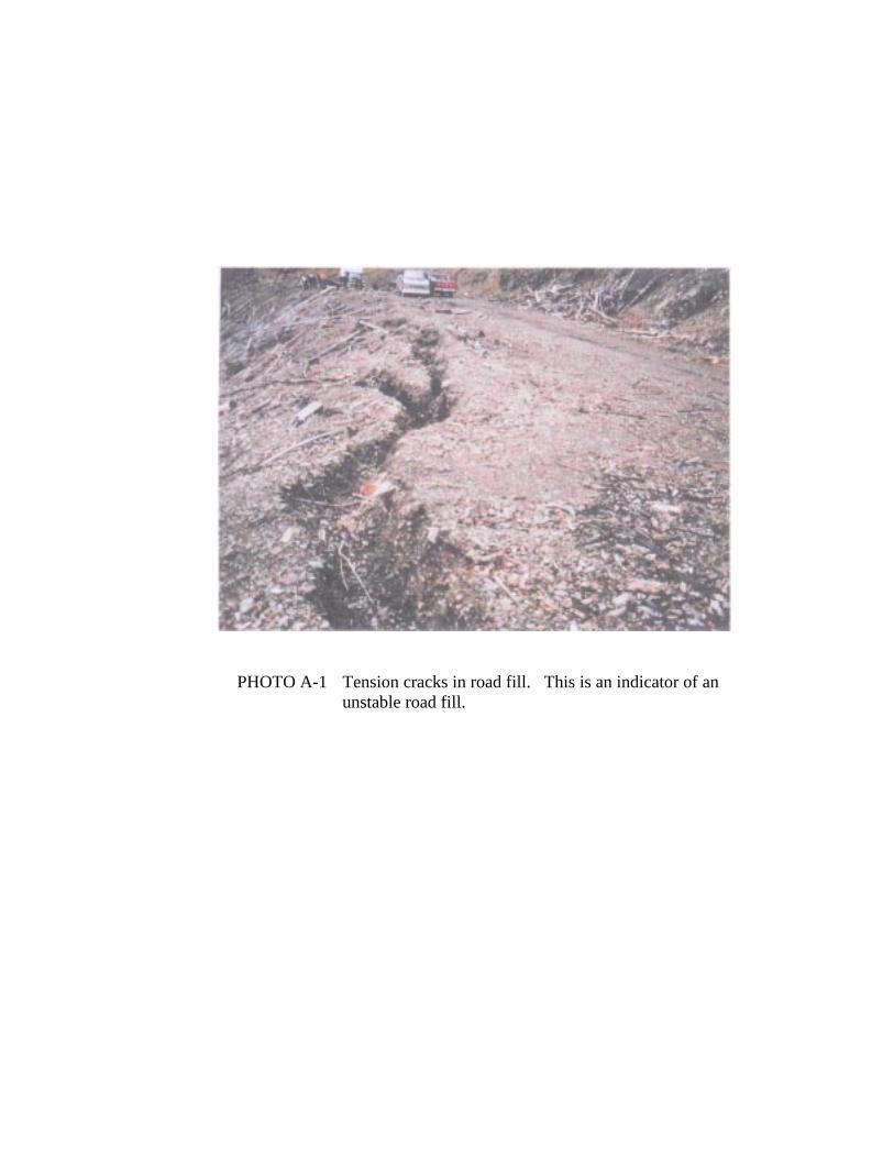
PHOTO A-1 Tension cracks in road fill. This is an indicator of anunstable road fill.
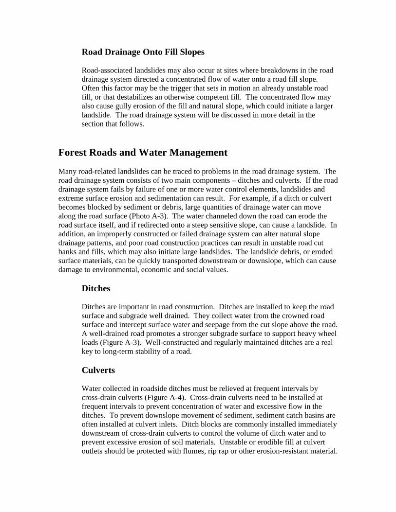
Road Drainage Onto Fill Slopes
Road-associated landslides may also occur at sites where breakdowns in the roaddrainage system directed a concentrated flow of water onto a road fill slope.Often this factor may be the trigger that sets in motion an already unstable roadfill, or that destabilizes an otherwise competent fill. The concentrated flow mayalso cause gully erosion of the fill and natural slope, which could initiate a largerlandslide. The road drainage system will be discussed in more detail in thesection that follows.
Forest Roads and Water Management
Many road-related landslides can be traced to problems in the road drainage system. Theroad drainage system consists of two main components – ditches and culverts. If the roaddrainage system fails by failure of one or more water control elements, landslides andextreme surface erosion and sedimentation can result. For example, if a ditch or culvertbecomes blocked by sediment or debris, large quantities of drainage water can movealong the road surface (Photo A-3). The water channeled down the road can erode theroad surface itself, and if redirected onto a steep sensitive slope, can cause a landslide. Inaddition, an improperly constructed or failed drainage system can alter natural slopedrainage patterns, and poor road construction practices can result in unstable road cutbanks and fills, which may also initiate large landslides. The landslide debris, or erodedsurface materials, can be quickly transported downstream or downslope, which can causedamage to environmental, economic and social values.
Ditches
Ditches are important in road construction. Ditches are installed to keep the roadsurface and subgrade well drained. They collect water from the crowned roadsurface and intercept surface water and seepage from the cut slope above the road.A well-drained road promotes a stronger subgrade surface to support heavy wheelloads (Figure A-3). Well-constructed and regularly maintained ditches are a realkey to long-term stability of a road.
Culverts
Water collected in roadside ditches must be relieved at frequent intervals bycross-drain culverts (Figure A-4). Cross-drain culverts need to be installed atfrequent intervals to prevent concentration of water and excessive flow in theditches. To prevent downslope movement of sediment, sediment catch basins areoften installed at culvert inlets. Ditch blocks are commonly installed immediatelydownstream of cross-drain culverts to control the volume of ditch water and toprevent excessive erosion of soil materials. Unstable or erodible fill at culvertoutlets should be protected with flumes, rip rap or other erosion-resistant material.
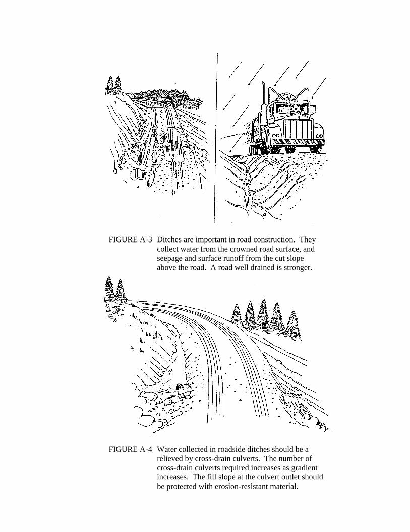
FIGURE A-3 Ditches are important in road construction. Theycollect water from the crowned road surface, andseepage and surface runoff from the cut slopeabove the road. A road well drained is stronger.
FIGURE A-4 Water collected in roadside ditches should be arelieved by cross-drain culverts. The number ofcross-drain culverts required increases as gradientincreases. The fill slope at the culvert outlet shouldbe protected with erosion-resistant material.

In addition to cross-drain culverts, which provide ditch water relief, streamculverts or fords should be installed at all crossings of established permanent orseasonal watercourses.
Culverts that are improperly installed and designed, and not maintained regularly,are directly or indirectly responsible for a large number of road-associatedlandslides.
Construction Factors
Both construction and maintenance factors can contribute to road-associatedlandslides as a result of problems in the road drainage network. Ditches causeproblems when they are constructed too shallow or when they do not havesufficient gradient. A deep ditch allows rapid drainage of the road subgrade orthe sidecast material, which reduces the build-up of high water pressures andhelps maintain high soil strength and improved slope stability. Water that maypond in shallow ditch lines can saturate the subgrade rather than drain it.
The gradient of ditches is largely determined by the gradient of the road. Thegradient should be sufficient to prevent ponding of ditch water; where grades arelow, the best way to prevent ponding is by installing more frequent cross drains.
Cross drain culverts should be spaced at appropriate intervals to minimize thetransport of sediment. Cross drain culvert spacing is a function of the road grade,soil type, and rainfall intensity. In general, cross-drain culverts that are spacedtoo far apart can allow ditches to collect too much water. On steep road gradientsthis can result in severe erosion of the ditchline and plugging of culvert inlets withsediment and debris. Wide culvert spacing can contribute to off-road failures bycollecting drainage from large areas and concentrating it onto small slope areas.
If ditches are ineffective, or if cross-drain culverts and stream culverts are sizedtoo small to accommodate peak ditch and stream flows, drainage water maybreach the road and flow across the road. This situation can quickly erode the fillslope, causing oversteepening and possibly slope failure.
A cascading outfall from the exit end of a cross-drain culvert can erode andundermine the fill slope. An apron of coarse rock or rip-rap installed over the fillslope at the outlet end of a culvert can prevent erosion and undercutting of theslope. An unprotected fill slope at a culvert outlet can result in significant erosion(Photo A-2). If the undercut slope is not repaired, a larger landslide can result.
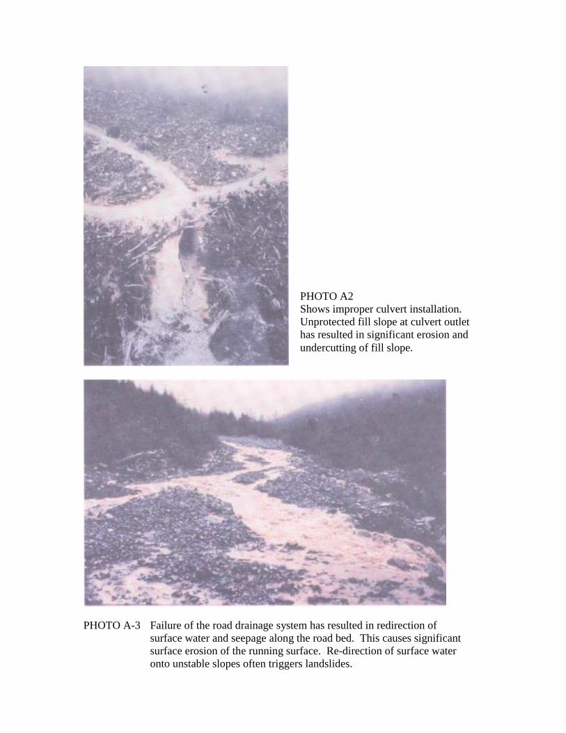
PHOTO A-3 Failure of the road drainage system has resulted in redirection ofsurface water and seepage along the road bed. This causes significantsurface erosion of the running surface. Re-direction of surface wateronto unstable slopes often triggers landslides.
PHOTO A2Shows improper culvert installation.Unprotected fill slope at culvert outlethas resulted in significant erosion andundercutting of fill slope.

Maintenance Factors
Although construction factors are commonly involved, most road fill slopefailures can be attributed to problems with road drainage, which occurs because ofinadequate maintenance of the road-side ditches and culverts. Regularmaintenance operations of the road drainage system include:
• cleaning and grading of ditches• cleaning and repairing culverts• inspections of drainage system structures after major storms, during spring
breakup and prior to fall rains to assess their adequacy
The quality of road construction governs the risk of slope failure in the short term,but maintenance of the ditches and culverts determines the road’s stability in thelong term. Hence, even if new roads are better built, and existing active roads arefully maintained and properly deactivated before maintenance funding terminates,the extensive network of old Abandoned roads that remain will continue to be asource of landslides, surface soil erosion and sedimentation.
Sediment production from roads can be caused by erosion of road surfaces,sidecast fills, cut bank slopes, and ditch line. Removal of sediment from erodingroad surfaces may also adversely affect road stability. As the road erodes, thedrainage capacity of ditches and culverts can be reduced, road banks undercut,and the road surface undermined. Such surface erosion can then lead to masserosion.
A large portion of this eroded material comes to rest in the road drainage system.While in the road drainage system, the soil will reduce the effective water-carrying capacities of the drainage structures, jeopardizing road stability and alsooverall slope stability. Hence, although surface erosion is not as spectacular asmass-wasting, it is a serious but less visible problem.
If the road drainage system is not regularly maintained, ditches fill in withsediment and culverts become plugged with sediment and debris. Ineffectiveditches and blocked culverts can cause ponding of water, saturation of the fillslope and breaching of the road. Blocked culverts are more often a problem thanare undersize culverts. Relatively minor blockages can lead to spectacular erosionand landslides.

Road Drainage and Off-Road Landslides
Poorly constructed road drainage systems, and/or lack or absence of drainagemaintenance, can alter natural slope drainage patterns. Plugged culverts or filledin ditches can permit road drainage to be channeled down the road (Photo A-3)and redirected across the road onto either unstable fill slopes, or sensitive naturalslopes downhill. The channeling of road drainage down the road will also causemajor surface soil erosion.
In addition, inadequate relief of ditch water can create major slope stabilityproblems. In this situation, runoff that would usually drain into natural drainagebasins may be conveyed away (in the ditchline) from the natural drainages into adrainage area that previously received less water. Pirating of water in this mannerincreases the size of the affected drainage area and may initiate large landslidesdownhill of the road location.
APPENDIX B
Explanation of Some CommonRoad Deactivation Measures

Cross-Ditches and Waterbars
Water management is the most important task in road deactivation. In lieu ofmaintenance, water control elements that require maintenance can frequently be“failsafed” by adding self-maintained water control elements to accomplish the sameobjectives. The water control element in this case is backup, i.e., an addition to thedrainage system that ensures control if another element fails because of unreliable orcomplete absence of maintenance. The backup element is typically less prone to failure,if properly installed, and hence is self-maintained. Restoring natural drainage patternscan be achieved by adding many self-maintained water control elements such as cross-ditches, waterbars, and outsloping or insloping the road grade.
The purpose of a cross-ditch (Figure B-1 and Photo B-1) is to capture and divert bothroad surface water and ditch water off and/or across the road, to prevent surface soilerosion, ditchline erosion, and concentration of drainage water (surface and subsurface).A cross-ditch directs and disperses surface water flow off a road to stable sites on thedownhill side of the road. Cross-ditches perform the same function as culverts, butunlike culverts, very little or no maintenance is required to ensure water flow when theyare properly constructed, placed in correct locations, and spaced closely.
An overflow cross-ditch provides an overflow channel across the road that will conveywater across without excessive erosion if/when an existing culvert plugs or its capacity isexceeded. An example of an overflow cross ditch is illustrated in Photo B-2.
The purpose of a waterbar (Figure B-1) is to prevent excessive flow down the roadsurface and erosion of road surface materials. The waterbar may be installed to captureand divert road surface water off the road and into the ditchline, or across the road. Thewaterbar is unlike the cross-ditch because ditch water is not a concern.
The locations or cross-ditches and waterbars are determined by grade, slope length,nature of the road surface materials, and surface and subsurface flows.
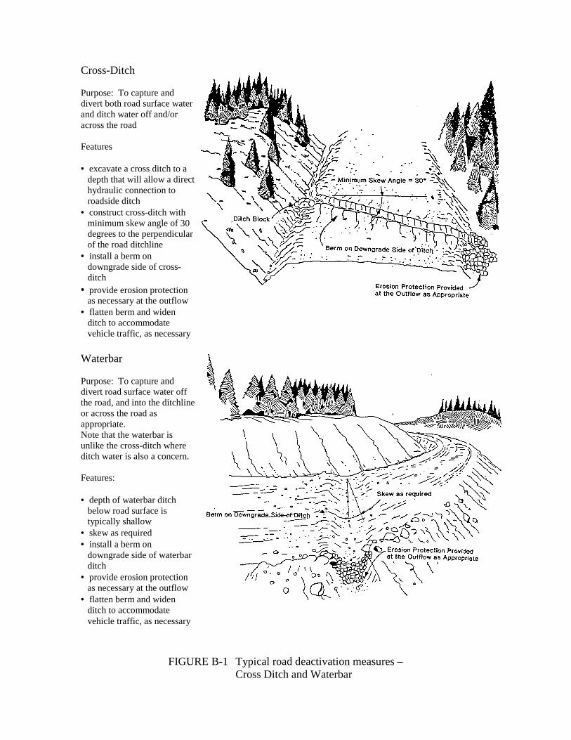
Cross-Ditch
Purpose: To capture anddivert both road surface waterand ditch water off and/oracross the road
Features
• excavate a cross ditch to adepth that will allow a directhydraulic connection toroadside ditch
• construct cross-ditch withminimum skew angle of 30degrees to the perpendicularof the road ditchline
• install a berm ondowngrade side of cross-ditch
• provide erosion protectionas necessary at the outflow
• flatten berm and widenditch to accommodatevehicle traffic, as necessary
FIGURE B-1 Typical road deactivation measures –Cross Ditch and Waterbar
Waterbar
Purpose: To capture anddivert road surface water offthe road, and into the ditchlineor across the road asappropriate.Note that the waterbar isunlike the cross-ditch whereditch water is also a concern.
Features:
• depth of waterbar ditchbelow road surface istypically shallow
• skew as required• install a berm on
downgrade side of waterbarditch
• provide erosion protectionas necessary at the outflow
• flatten berm and widenditch to accommodatevehicle traffic, as necessary
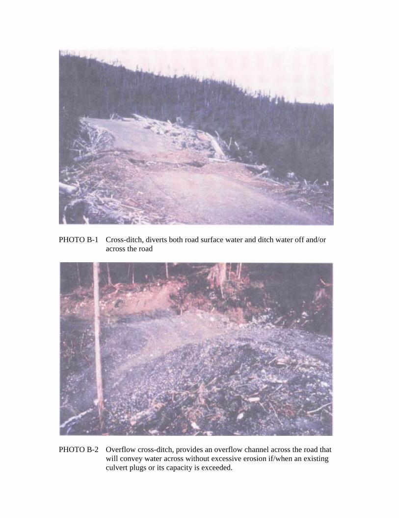
PHOTO B-1 Cross-ditch, diverts both road surface water and ditch water off and/oracross the road
PHOTO B-2 Overflow cross-ditch, provides an overflow channel across the road thatwill convey water across without excessive erosion if/when an existingculvert plugs or its capacity is exceeded.
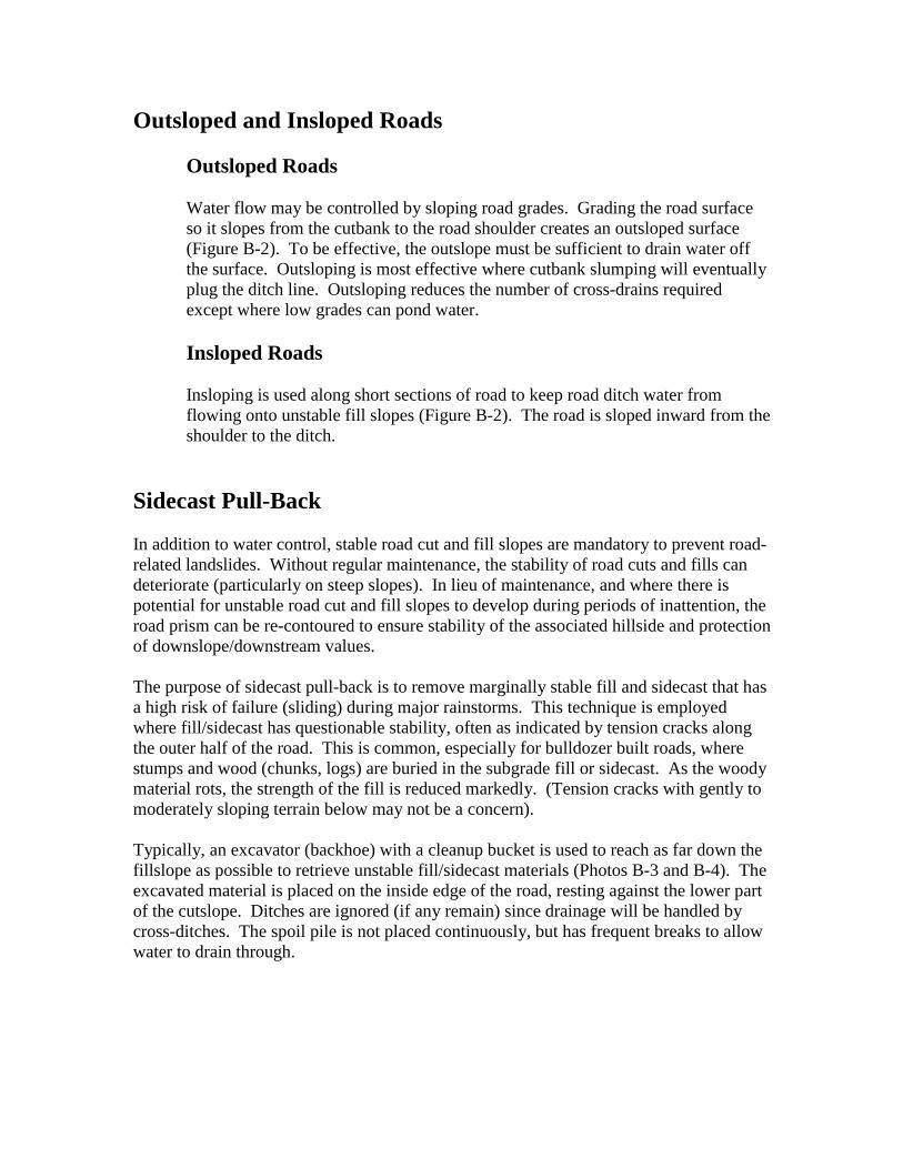
Outsloped and Insloped Roads
Outsloped Roads
Water flow may be controlled by sloping road grades. Grading the road surfaceso it slopes from the cutbank to the road shoulder creates an outsloped surface(Figure B-2). To be effective, the outslope must be sufficient to drain water offthe surface. Outsloping is most effective where cutbank slumping will eventuallyplug the ditch line. Outsloping reduces the number of cross-drains requiredexcept where low grades can pond water.
Insloped Roads
Insloping is used along short sections of road to keep road ditch water fromflowing onto unstable fill slopes (Figure B-2). The road is sloped inward from theshoulder to the ditch.
Sidecast Pull-Back
In addition to water control, stable road cut and fill slopes are mandatory to prevent road-related landslides. Without regular maintenance, the stability of road cuts and fills candeteriorate (particularly on steep slopes). In lieu of maintenance, and where there ispotential for unstable road cut and fill slopes to develop during periods of inattention, theroad prism can be re-contoured to ensure stability of the associated hillside and protectionof downslope/downstream values.
The purpose of sidecast pull-back is to remove marginally stable fill and sidecast that hasa high risk of failure (sliding) during major rainstorms. This technique is employedwhere fill/sidecast has questionable stability, often as indicated by tension cracks alongthe outer half of the road. This is common, especially for bulldozer built roads, wherestumps and wood (chunks, logs) are buried in the subgrade fill or sidecast. As the woodymaterial rots, the strength of the fill is reduced markedly. (Tension cracks with gently tomoderately sloping terrain below may not be a concern).
Typically, an excavator (backhoe) with a cleanup bucket is used to reach as far down thefillslope as possible to retrieve unstable fill/sidecast materials (Photos B-3 and B-4). Theexcavated material is placed on the inside edge of the road, resting against the lower partof the cutslope. Ditches are ignored (if any remain) since drainage will be handled bycross-ditches. The spoil pile is not placed continuously, but has frequent breaks to allowwater to drain through.
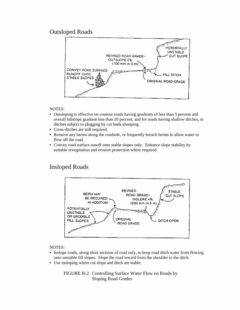
Outsloped Roads
NOTES:• Outsloping is effective on contour roads having gradients of less than 5 percent and
overall hillslope gradient less than 20 percent, and for roads having shallow ditches, orditches subject to plugging by cut bank slumping.
• Cross-ditches are still required.• Remove any berms along the roadside, or frequently breach berms to allow water to
flow off the road.• Convey road surface runoff onto stable slopes only. Enhance slope stability by
suitable revegetation and erosion protection where required.
Insloped Roads
NOTES:• Inslope roads, along short sections of road only, to keep road ditch water from flowing
onto unstable fill slopes. Slope the road inward from the shoulder to the ditch.• Use insloping where cut slope and ditch are stable.
FIGURE B-2 Controlling Surface Water Flow on Roads bySloping Road Grades
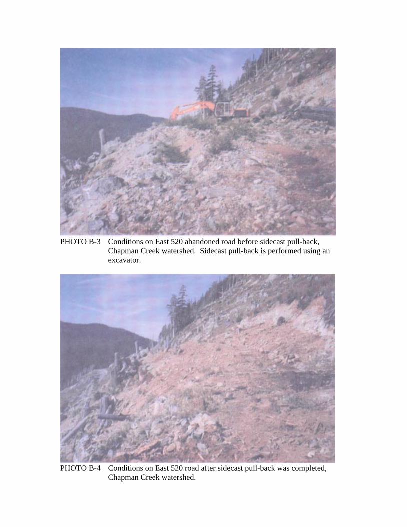
PHOTO B-3 Conditions on East 520 abandoned road before sidecast pull-back,Chapman Creek watershed. Sidecast pull-back is performed using anexcavator.
PHOTO B-4 Conditions on East 520 road after sidecast pull-back was completed,Chapman Creek watershed.

Revegetation
Revegetation measures, including seeding of erosion control mixes, and planting ofshrubs and trees are best applied after physical stability has been attained. Revegetationof exposed mineral soils associated with the road system and slide tracks and masswasting areas is necessary to minimize erosion and sedimentation of streams and to addsignificant root strength to total soil strength .
If limited road access is maintained, then fillslopes should be grass seeded. Where roaddeactivation practices involve sidecast pull-back and the planned loss of road access, allexposed mineral soils (cuts, road surface, pull-back material piled on road, and fillslopes)would require revegetation (Figure B-3 and Photo B-5).
If the objective is to return the site to productive forest, the road surface is decompacted(as appropriate) and planted with suitable conifers.
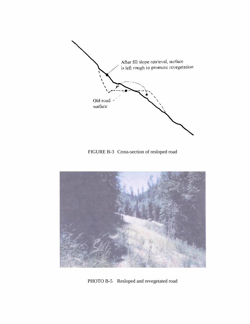
FIGURE B-3 Cross-section of resloped road
PHOTO B-5 Resloped and revegetated road

APPENDIX C
Tschaplinskly, P. J. (1992). Effects of Roads on Freshwater Fish Habitats andFish Production. Victoria, British Columbia: ResearchBranch, B.C. Ministry of Forests

Effects of Roads on Freshwater Fish Habitats and FishProduction
Introduction
Forest harvest causes a number of physical changeswithin watersheds which affect a spectrum of physical,chemical, and biological processes. However, forest harvestinvolves a complex spectrum of activities including roadconstruction and maintenance, falling, yarding, and post-harvest silviculture treatments including prescribed burning,scarification, tree planting, and herbicide use. Each ofthese activities has specific effects and biologicalconsequences; however, the effects of many of these activitiesare overlapping and occur at the same time that fishpopulations are managed for both commercial and sportfisheries.
Interactions between complex aquatic ecosystems,which are variable both spatially and temporally, with themultiple and concurrent effects of both forest-harvest andfish-harvest management makes separation of cause-and-effectrelationships for watersheds and their fish species difficult.Therefore, quantifying the specific effects of one componentsuch as forest roads on fish habitats and production requireslong-term, time-series studies of ecosystem processes in orderto accurately quantify and partition the effects of manyinteracting variables. Despite this complexity, several long-term investigations conducted in British Columbia, WashingtonState, and Oregon have demonstrated some clear effects of roadconstruction, operation, and maintenance on watershedprocesses and the abundance and survival of resident fishpopulations.
Forestry-related activities are not always harmfulto freshwater fish populations. For example, a long-term,intensive study of logging on fish populations in CarnationCreek, Vancouver Island revealed that the annual growth ofjuvenile coho salmon (Oncorhynchus kisutch) actually increasedin years immediately after logging due to increases in air andwater temperatures in the drainage basin after forest canopyremoval. Larger size permitted these fry and yearlings tosurvive the winter in refuge habitats at higher rates thanwere observed prior to logging (Hartman and Scrivener 1990;Holtby 1988; Tschaplinski and Hartman 1983). However, no suchpositive effects on fish growth and survival have ever beenassociated with the construction, use, or maintenance offorest roads.

�
Discussion
Road-related changes that are harmful to fishhabitats and fish populations are brought about principally byalterations to the input, character, and transport of water,sediment, and organic matter through the stream system. Thesechanges, despite linkages, can be divided broadly intoalterations in hydrologic regime and sedimentation.
Hydrological Effects
Many hydrological changes associated with forestryare directly attributable to roads. At Carnation Creek, roadconstruction interrupted sub-surface water flow, increasedsurface erosion, and re-routed water in the drainage basinthrough culverts and ditches to the fish-bearing part of thestream such that: (1) time between peak rainfall and peakstream discharge was reduced, and consequently, (2) peakseasonal flows increased in magnitude and erosive energy(Cheng 1988; Hetherington 1982, 1988).
Increased erosive energy is especially harmful tofish habitats and fish survival in winter when heavy rainfalloccurs frequently. Seasonal increases in the frequency andseverity of landslides, and subsequent reductions in chinook(O. tshawytscha) and coho populations were associated withroads in the Clearwater River drainage in the western slopesof the Olympic Mountains, Washington (Cederholm et al. 1978,Cederholm and Lestelle 1974, Cederholm and Reid 1987,Cederholm and Salo 1979).
Increased peak flows due to road-related hydrologicchanges resulted in debris torrents entering winter refugehabitats used by juvenile salmonids, and morphologicalalterations to main fish-bearing streams by scouring spawninggravels and causing large movements of stream substrates(Cederholm et al. 1981). Stream channel erosion thus resultedin less habitat suitable for salmonid spawning and eggincubation during autumn and winter. Additionally, lessrearing habitat was available for juveniles in summer becausebedload movements filled in pools which also became lessabundant due to the removal large woody debris necessary fortheir stability. During one winter following roadconstruction, 40 – 50 % of previously-constructed redds weredestroyed by streambed scour and bedload movements (Cederholmet al. 1981, Cederholm and Salo 1979). These observationsclearly illustrated the sensitivity of salmon eggs and alevinsto hydrologic conditions and were consistent with thediscovery of a significant inverse relationship betweenchinook fry abundance in summer and maximum peak discharge of

�
the previous winter in these northwestern Washington streams(Cederholm et al. 1981, 1987). Clearly, even small increasesin the magnitude and frequency of peak discharges can reducethe survival of salmon eggs and alevins in streams.
Sedimentation
It is widely accepted that high levels ofsedimentation lower salmonid production from freshwaterenvironments (Gibbons and Salo 1973, Iwamoto et al. 1978,Everest et al. 1978). All salmon life stages are adverselyaffected by sedimentation. Mortality in eggs and alevins hasbeen shown to be due to increases in fine sediments throughreductions of stream gravel porosity, intragravel flows, anddissolved oxygen concentrations (Everest et al. 1987; Hall1984; Koski 1966, 1975; Wickett 1954, 1958). Eggs andemerging fish may be buried and can suffocate when excessivefine sediments infiltrate spawning/incubation gravels (Koski1975).
Eggs, alevins, and older juvenile salmonids may alsobe stranded in secondary channels due to coarse sedimentinflux in combination with road-related hydrological changes.Sedimentation may cause some of these channels to become dryin summer. For example, one tributary in the Clearwater Riverdrainage became seasonally dry after a road-related debristorrent caused heavy sediment deposition. Annual smoltproduction from that tributary consequently fell from 350 –1 000 fish to 50 – 400 fish (Cederholm and Reid 1987).
Direct habitat reductions for stream-dwellingjuvenile salmonids can occur through reductions in pool depthand alterations in channel morphology in both summer rearingareas in streams and in winter refuge habitats in smallfloodplain channels (Cederholm and Reid 1987).
Fry, smolts and adult salmonids can bephysiologically stressed by turbidity due to the input of finesediments alone into streams. High levels of suspendedsediments can kill fish by abrading and clogging their gills.Campbell (1954) reported that caged rainbow trout (O. mykiss)were killed within 20 days in the Powder River, Oregon whensuspended sediment concentrations were 1 000 – 2 500 ppm.
Finally, increases in sedimentation on aquaticsubstrates and within them have been shown to reduce (1) themacroinvertebrate food resources which juvenile salmonids usefor food (Culp and Davies 1983, Ziebell 1960), and (2) primaryproducers which support some of these invertebratepopulations. Hynes (1960) reported that high turbidity due toheavy sediment loads can prevent photosynthesis. Culp and

�
Davies (1983) showed that macroinvertebrate densities insummer were reduced by 23 – 50 % during logging in CarnationCreek. Culp et al. (1986) experimentally introduced finesediments (0.5 – 2.0 mm in diameter) into Carnation Creekriffles and observed 50 % reductions in macroinvertebratebiomass and abundance within 24 hours.
All species of salmonids in freshwater habitats areadversely affected by excess sedimentation. For example,sediment-related changes in channel morphology and diversityof rearing and overwintering habitats will affect all streamfishes, especially coho salmon, some chinook, and rainbow andcutthroat trout (O. clarki) because these species may spendone or more years in streams and lakes. However, even speciessuch as pink salmon (O. gorbuscha) and chum (O. keta), whosefry leave streams for the ocean shortly after they emerge fromthe stream gravel, are sensitive to sedimentation. Everest etal. (1987) thought that fine-particle sedimentation from roadsurfaces probably presented a greater hazard to the eggs andalevins of pink and chum because (1) these species spawn inthe lowermost reaches of streams where fine-sedimentdeposition is frequently prevalent, and (2) roads produce achronic supply of fine-grained sediments.
Conclusions drawn by Everest et al. (1987) aresupported by observations made elsewhere. Hartman andScrivener (1990) summarized that egg-to-fry survivals inCarnation Creek were reduced by one-half for both chum andcoho salmon between pre-logging and post-logging periods.Prior to logging, survivals were 20.3 and 28.8 % for chum andcoho salmon respectively. These respective percentages fellto 10.9 and 15.6 % in post-logging years. Annual chumescapements to Carnation Creek fell drastically frompre-logging and during-logging levels of 275 – 4 168 to only28 adults in 1991. Although logging-related effects such assedimentation were clearly only one factor, this reduction instock size was dramatic and parallels other southern BC stocksof chum salmon which face the dual impacts of freshwaterhabitat deterioration and reductions in marine survival.
Numerous studies have shown that forest roads areprincipal sources of logging-related sediment in streams(Brown and Krygier 1971, Cederholm et al. 1981, Cederholm andReid 1987, Megahan and Kidd 1972, Reid et al. 1981, Rice etal. 1979). For example, Beschta (1978) reported that annualyields of fine sediments (<0.85 mm diameter) increased from27 – 97 tons/km 2 to 90 – 300 tons/km 2 after road constructionand forest harvesting in the Alsea watershed, Oregon.
An intensive (eight-year) study involving 45 salmonproducing sub-basins within the Clearwater River system inwestern Washington revealed that anadromous fish populations
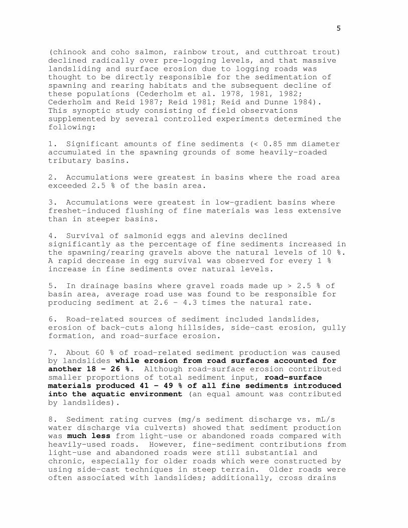
�
(chinook and coho salmon, rainbow trout, and cutthroat trout)declined radically over pre-logging levels, and that massivelandsliding and surface erosion due to logging roads wasthought to be directly responsible for the sedimentation ofspawning and rearing habitats and the subsequent decline ofthese populations (Cederholm et al. 1978, 1981, 1982;Cederholm and Reid 1987; Reid 1981; Reid and Dunne 1984).This synoptic study consisting of field observationssupplemented by several controlled experiments determined thefollowing:
1. Significant amounts of fine sediments (< 0.85 mm diameteraccumulated in the spawning grounds of some heavily-roadedtributary basins.
2. Accumulations were greatest in basins where the road areaexceeded 2.5 % of the basin area.
3. Accumulations were greatest in low-gradient basins wherefreshet-induced flushing of fine materials was less extensivethan in steeper basins.
4. Survival of salmonid eggs and alevins declinedsignificantly as the percentage of fine sediments increased inthe spawning/rearing gravels above the natural levels of 10 %.A rapid decrease in egg survival was observed for every 1 %increase in fine sediments over natural levels.
5. In drainage basins where gravel roads made up > 2.5 % ofbasin area, average road use was found to be responsible forproducing sediment at 2.6 – 4.3 times the natural rate.
6. Road-related sources of sediment included landslides,erosion of back-cuts along hillsides, side-cast erosion, gullyformation, and road-surface erosion.
7. About 60 % of road-related sediment production was causedby landslides while erosion from road surfaces accounted foranother 18 – 26 %. Although road-surface erosion contributedsmaller proportions of total sediment input, road-surfacematerials produced 41 – 49 % of all fine sediments introducedinto the aquatic environment (an equal amount was contributedby landslides).
8. Sediment rating curves (mg/s sediment discharge vs. mL/swater discharge via culverts) showed that sediment productionwas much less from light-use or abandoned roads compared withheavily-used roads. However, fine-sediment contributions fromlight-use and abandoned roads were still substantial andchronic, especially for older roads which were constructed byusing side-cast techniques in steep terrain. Older roads wereoften associated with landslides; additionally, cross drains

�
on these roads were often poorly protected from gully erosionand frequently resulted in undercutting of fills and eventualslumping. Newer road-building methods incorporating erosion-prevention measures vastly reduced these problems.
The overall conclusions from studies in theClearwater River drainage were that production of sedimentsfrom logging roads resulted in significant decreases insalmonid (especially coho salmon) egg survival to emergence,and thus lowered the success of salmonid spawning andrecruitment from this major drainage basin. These reductionswere potentially serious for some small and sensitive stocksof coho salmon which at the same time were being heavilyfished in coastal marine waters (Cederholm et al. 1981,Cederholm and Reid 1987).
From the results of Clearwater River study, theinvestigators recommended several alternative methods of roadconstruction, erosion prevention, and forest harvesttechniques to reduce the effect of roads on salmonidpopulations. One recommendation was to put old roads “tobed”; that is, to close them off to traffic and to water-barthem to prevent surface erosion.
The intrusion of fine-grained sediments in theClearwater system was the most significant forestry-relatedadverse effect on its fish populations. The effects of road-related sedimentation on fish will certainly varygeographically according to local conditions of hydrology,geology, stream gradient and geometry, and dominant erosion-transport processes (Everest et al. 1987). However,persistent sediment sources such as roads are potentially moredetrimental than other, more temporary, sources. Roadsurfaces are subject to repeated heavy rains and freshets, andcan cause fine sediments to accumulate in streams and relatedaquatic habitats for years whenever their introduction ratesoutstrip their rates of removal by scour. Salmonid fisheriesresources are clearly economically and socially important inwestern North America. One relatively inexpensive method toprotect these resources from excess sedimentation infreshwater environments after local forestry-relatedactivities are concluded, is to deactivate road systems inwatersheds.
�
REFERENCES CITED
BESCHTA, R. L. 1978. Long-term pattern of sediment productionfollowing road construction and logging in the Oregoncoast range. Water Resour. Res. 14: 1011 – 1016.
BROWN, G. W. and J. T. KRYGIER. 1971. Clear-cut logging andsediment production in the Oregon Coast Range. WaterResour. Res. 7(5): 1189 – 1198.
CAMPBELL, H. J. 1954. The effect of siltation from golddredging on survival of rainbow trout and eyed eggs inPowder River, Oregon. Oregon State Game Commission Report.3p.
CEDERHOLM, C. J. and L. C. LESTELLE. 1974. Observations onthe effects of landslide siltation on salmon and troutresources of the Clearwater River, Jefferson County,Washington, 1972 – 1973. Final Report: Part 1. FRI-UW-7404. Fisheries Research Institute, University ofWashington, Seattle. 89 p.
CEDERHOLM, C. J. AND L. C. LESTELLE, B. G. EDIE, D. J. MARTIN,J. V. TAGGART, and E. O. SALO. 1978. Observations on theeffects of landslide siltation on salmon and troutresources of Stequaleho Creek and the main ClearwaterRiver, Jefferson County, Washington, 1972 - 1975. FinalReport: Part 2. FRI-UW-7804. Fisheries ResearchInstitute, University of Washington, Seattle. 53 p.
CEDERHOLM, C. J. and L. M. Reid. 1987. Impact of forestmanagement on coho salmon (Oncorhynchus kisutch)populations in the Clearwater River, Washington. InStreamside management: Forestry and fishery interactions.Edited by E. O. Salo and T. W. Cundy. University ofWashington, Institute of Forest Resources Contribution No.57. pp. 373 – 398.
CEDERHOLM, C. J., L. M. REID, B. G. EDIE, and E.O. SALO.1982. Effects of forest road erosion on salmonid spawninggravel composition and populations of the ClearwaterRiver, Washington. In Habitat disturbance and recovery:Proceedings of a symposium. pp. 1 – 17. California TroutInc., San Francisco. CA.

�
CEDERHOLM, C. J., L. M. REID, and E. O. SALO. 1981.Cumulative effects of logging road sediment on salmonidpopulations in the Clearwater River, Jefferson County,Washington. In Proceedings from the conference. Salmon-spawning gravel: A renewable resource in the Pacificnorthwest? pp. 39 – 74. Rep. 39. State of WashingtonWater Research Center, Pullman, WA.
CEDERHOLM, C. J. and E. O. SALO. 1979. The effects oflogging road landslide siltation on salmon and troutspawning gravels of Stequaleho Creek and the ClearwaterRiver basin, Jefferson County, Washington, 1972 – 1978.Final Report: Part 2. FRI-UW-7915. Fisheries ResearchInstitute, University of Washington, Seattle. 99pp.
CHENG, J. D. 1988. Subsurface stormflows in the highlypermeable forested watersheds of southwestern BritishColumbia. J. Contam. Hydro. 3: 171 – 191.
CULP, J. M. and R. W. DAVIES. 1983. An assessment of theeffects of streambank clear-cutting on macroinvertebratecommunities in a managed watershed. Can. Tech. Rep. Fish.Aquat. Sci. 1208: 116 p.
CULP, J. M., F. J. WRONA, and R. W. DAVIES. 1986. Responsesof stream benthos and drift to fine sediment depositionversus transport. Can. J. Zool. 64: 1345 – 1351.
EVEREST, F. H., R. L. BESCHTA, J. C. SCRIVENER, K. V. KOSKI,J. R. SEDELL, and C. J. CEDERHOLM. 1987. Fine sedimentsand salmonid production: A paradox. In Streamsidemanagement: Forestry and fishery interactions. Edited byE. O. Salo and T. W. Cundy. University of Washington,Institute of Forest Resources Contribution No. 57. pp. 98– 142.
GIBBONS, D. R. and E. O. SALO. 1973. An annotatedbibliography of the effects of logging on fish of thewestern United States and Canada. USDA For. Serv. Gen.Tech. Rep. PNW-10. Pac. Northwest For. and Range Exp.Stn., Portland Oregon. 145 p.
HALL, T. 1984. A laboratory study of the effects ofsediments of two different size characteristics onsurvival of rainbow trout (Salmo gairdneri) embryos to fryemergence. Tech. Bull. 492. National Council of thePaper Industry for Air and Stream Improvement. 49 p.
HARTMAN, G. F. and J. C. SCRIVENER. 1990. Impacts offorestry practices on a coastal stream system, CarnationCreek, British Columbia. Can. Bull. Fish. Aquat. Sci.223: 148 p.

�
HETHERINGTON, E. D. 1982. A first look at logging effects onthe hydrologic regime of Carnation Creek experimentalwatershed. In Proceedings of the Carnation Creekworkshop, A 10-year review. 24 – 26 February 1982. pp.45 – 63. Edited by G. F. Hartman. Pacific BiologicalStation, Nanaimo, BC. 404 p.
HETHERINGTON, E. D. 1988. Hydrology and logging in theCarnation Creek watershed - what have we learned? pp. 11- 15. In Proceedings of the workshop: Applying 15 yearsof Carnation Creek results. 13 - 15 January 1987. Editedby T. W. Chamberlin. Pacific Biological Station, Nanaimo,BC. 239 p.
HOLTBY, L. B. 1988. Effects of logging on streamtemperatures in Carnation Creek, British Columbia, andassociated impacts on the coho salmon (Oncorhynchuskisutch). Can. J. Fish. Aquat. Sci. 45: 502 – 515.
HYNES, H. B. N. 1960. The biology of polluted waters.Liverpool University Press, Liverpool, England. 202 p.
IWAMOTO, R. N., E. O. SALO, M. A. MADEJ, and R. L. MCCOMAS.1978. Sediment and water quality: A review of theliterature including a suggested approach for waterquality criteria. U.S. Environmental Protection Agency,Region 10, Seattle. 151 p.
KOSKI, K. V. 1966. The survival of coho salmon (Oncorhynchuskisutch) from egg deposition to emergence in three Oregoncoastal streams. M.Sc. Thesis. Oregon State University,Corvallis, OR. 84 p.
KOSKI, K. V. 1975. The survival and fitness of two stocks ofchum, salmon (Oncorhynchus keta) from egg deposition toemergence in a controlled stream environment at Big BeefCreek. Ph.D. Thesis. University of Washington, Seattle,WA. 212 p.
MEGAHAN, W. F. and W. J. KIDD JR. 1972. Effects of loggingroads on sediment production rates in the Idaho batholith.USDA For. Serv. Res. Pap. INT-123. Intermountain For. andRange Exp. Stn., Ogden, UT. 14 p.
REID, L. M. 1981. Sediment production from gravel-surfacedforest roads, Clearwater basin, Washington. FRI-UW-8108.Fisheries Research Institute, University of Washington,Seattle. 247 p.
REID, L. M. and T. DUNNE. 1984. Sediment production fromforest road surfaces. Water Resour. Res. 20(11): 1753 –1761.

��
REID, L. M., T. DUNNE, and C. J. CEDERHOLM. 1981.Application of sediment budget studies to the evaluationof logging road impact. NZ. J. Hydrol. 20: 49 – 62.
RICE, R. M., F. B. TILLEY, and P. DATZMAN. 1979. Awatershed’s response to logging and roads: South fork ofCaspar Creek, California, 1967 – 1976. USDA For. Serv.Res. Pap. PSW-146. Pac. Southwest For. and Range Exp.Stn., Berkeley, CA. 12 p.
TSCHAPLINSKI, P. J. and G. F. HARTMAN 1983. Winterdistribution of juvenile coho salmon (Oncorhynchuskisutch) before and after logging in Carnation Creek,British Columbia, and some implications for overwintersurvival. Can. J. Fish. Aquat. Sci. 40: 452 – 461.
WICKETT, W. P. 1954. The oxygen supply to salmon eggs inspawning beds. J. Fish. Res. Board Can. 11(6): 933 –953.
WICKETT, W. P. 1958. Review of certain factors affecting theproduction of pink and chum salmon. J. Fish. Res. BoardCan. 15(5): 1103 – 1126.
ZIEBELL, C. D. 1960. Problems associated with spawning andgrowth of salmonids in Northwest watersheds. Proceedings,seventh symposium on water pollution research. UnitedStates Department of Health, Education, and Welfare,Portland, OR.
APPENDIX D
Types of Resource Roads, Logging Trails,and Permits
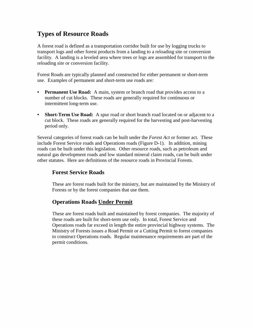
Types of Resource Roads
A forest road is defined as a transportation corridor built for use by logging trucks totransport logs and other forest products from a landing to a reloading site or conversionfacility. A landing is a leveled area where trees or logs are assembled for transport to thereloading site or conversion facility.
Forest Roads are typically planned and constructed for either permanent or short-termuse. Examples of permanent and short-term use roads are:
• Permanent Use Road: A main, system or branch road that provides access to anumber of cut blocks. These roads are generally required for continuous orintermittent long-term use.
• Short-Term Use Road: A spur road or short branch road located on or adjacent to acut block. These roads are generally required for the harvesting and post-harvestingperiod only.
Several categories of forest roads can be built under the Forest Act or former act. Theseinclude Forest Service roads and Operations roads (Figure D-1). In addition, miningroads can be built under this legislation. Other resource roads, such as petroleum andnatural gas development roads and low standard mineral claim roads, can be built underother statutes. Here are definitions of the resource roads in Provincial Forests.
Forest Service Roads
These are forest roads built for the ministry, but are maintained by the Ministry ofForests or by the forest companies that use them.
Operations Roads Under Permit
These are forest roads built and maintained by forest companies. The majority ofthese roads are built for short-term use only. In total, Forest Service andOperations roads far exceed in length the entire provincial highway systems. TheMinistry of Forests issues a Road Permit or a Cutting Permit to forest companiesto construct Operations roads. Regular maintenance requirements are part of thepermit conditions.
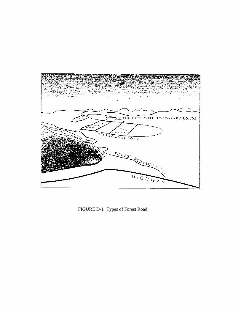
FIGURE D-1 Types of Forest Road
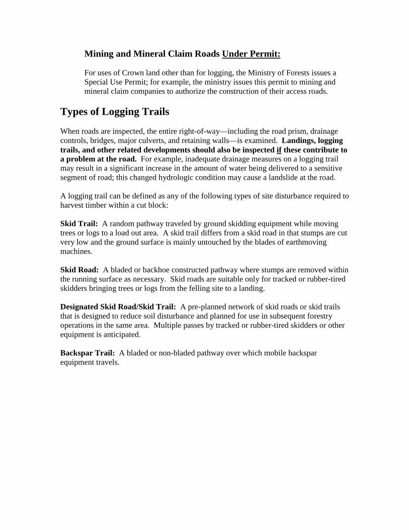
Mining and Mineral Claim Roads Under Permit:
For uses of Crown land other than for logging, the Ministry of Forests issues aSpecial Use Permit; for example, the ministry issues this permit to mining andmineral claim companies to authorize the construction of their access roads.
Types of Logging Trails
When roads are inspected, the entire right-of-way—including the road prism, drainagecontrols, bridges, major culverts, and retaining walls—is examined. Landings, loggingtrails, and other related developments should also be inspected if these contribute toa problem at the road. For example, inadequate drainage measures on a logging trailmay result in a significant increase in the amount of water being delivered to a sensitivesegment of road; this changed hydrologic condition may cause a landslide at the road.
A logging trail can be defined as any of the following types of site disturbance required toharvest timber within a cut block:
Skid Trail: A random pathway traveled by ground skidding equipment while movingtrees or logs to a load out area. A skid trail differs from a skid road in that stumps are cutvery low and the ground surface is mainly untouched by the blades of earthmovingmachines.
Skid Road: A bladed or backhoe constructed pathway where stumps are removed withinthe running surface as necessary. Skid roads are suitable only for tracked or rubber-tiredskidders bringing trees or logs from the felling site to a landing.
Designated Skid Road/Skid Trail: A pre-planned network of skid roads or skid trailsthat is designed to reduce soil disturbance and planned for use in subsequent forestryoperations in the same area. Multiple passes by tracked or rubber-tired skidders or otherequipment is anticipated.
Backspar Trail: A bladed or non-bladed pathway over which mobile backsparequipment travels.

Types of Permits
On Crown land, works cannot be carried out, and resource roads cannot be built ormodified, without the appropriate authorization. The following permits are issued andadministered by the Ministry of Forests:
1. F.S. 582 Road Permit (Build, Modify and Use): Part 8 of the Forest Act deals withRoads and Right-of-Way and provides the authority to access timber. Roadconstruction for harvesting purposes must be authorized by either a Road Permit (FS582) or a cutting authority. All roads other than those spurs situated on a cut block,must be authorized by a Road Permit (FS 582).
The Road Permit is issued to forest companies to construct Operations roads whenthey have a right to harvest timber. Maintenance, and now deactivation requirements,are part of the Road Permit condition. The Road Permit also authorizes the use ormodifications of existing abandoned roads for timber harvesting. Since loggingactivities frequently move from place to place and new permits are issued and oldones expire, the number of kilometres of Operations roads and abandoned roads arealways in a constant state of influx.
2. F.S. 102 Road Use Permit (Use of a Forest Service Road): The Road Use Permitis issued to all industrial users of Forest Service roads unless exempted by a DistrictManager. Among other purposes, the Road Use Permit controls maintenanceoperations on Forest Service roads, especially where there are several industrial userssharing a common road.
3. F.S. Special Use Permit: The Special Use Permit is used to authorize the use ofCrown land in Provincial Forests. Typical use of Crown land by mining companies isthe construction of an access road to mine or a mineral claim.
4. Cutting Permit: The Cutting Permit document or, in the case of the Small BusinessForest Enterprise Program (SBFEP), the Timber Sale Licence (and associatedamendments), constitutes the legal cutting authority.
The authority for requiring a Cutting Permit before harvesting can begin is found inthe Forest Act and pertains to major tenures as follows.
1. Forest Licence Forest Act, Section 12(f)2. Tree Farm Licence Forest Act, Section 28(f)3. Timber Sale Licence Forest Act, Section 17(d)4. Timber Licence Forest Act, Section 25(f)

APPENDIX E
British Columbia. B.C. Ministry of Forest (1993). Risk Assessment Procedure.Engineering Manual - Chapter 8. Victoria, British Columbia:Engineering Section, Timber Harvesting Branch (pp. 7-20).

)6�����+7+������
CHAPTER
Province of Ministry ofBritish Columbia Forests
CHAPTER 8 - MonitoringLicensees’ Forest Road Practices
SECTION
ENGINEERING MANUAL 8.3 Risk Assessment Procedure
REVISION NO. DATE PAGE
July 1993 7
8.3 Risk Assessment Procedure
Currently, the ministry’s Engineering Program requires that risk assessment beused as a decision-making tool for:
1. preparing the engineering component of Forest Development Plans(see Chapter 9);
2. providing a rationale for “triggering” a road survey and design submission(see Chapter 9); and
3. allocating staff and funding for effective and efficient monitoring of licensees’forest road practices.
This chapter deals with risk management, and risk assessment, for purposes ofallocating staff and funding to monitoring activities.
Purpose of Risk Management and Risk Assessment:
Risk Management is a rational decision-making process. It involves planning,organizing, directing and controlling resources to minimize detrimental impacts atthe least possible costs.
Risk assessment is the basis for allocating staff and funding. Roads that imposehigher risks to on-site/downslope/downstream values require more frequent, andintense, monitoring than roads that impose lower risks. The ministry selects thedegree of risk it can afford to accept and then allocates suitable resources to carryout the corresponding level of monitoring.
The ministry uses two approaches to monitor road development activities:
• a process-oriented monitoring program• a results-oriented monitoring program
All roads require a results-oriented monitoring program to assess the impact of thefinal road construction works on user safety, and to determine that workconformed with the ministry’s Forest Road and Logging Trail EngineeringPractices (Interim) document.
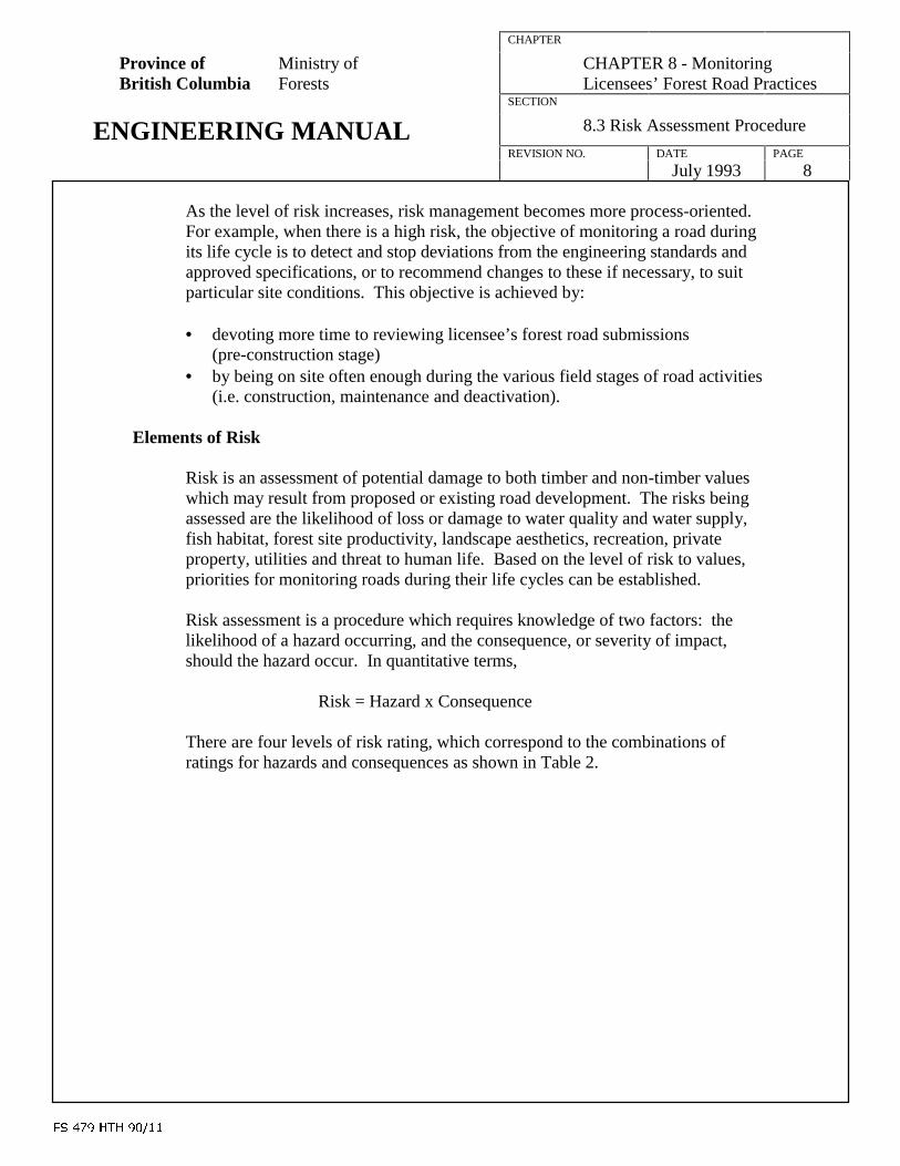
)6�����+7+������
CHAPTER
Province of Ministry ofBritish Columbia Forests
CHAPTER 8 - MonitoringLicensees’ Forest Road Practices
SECTION
ENGINEERING MANUAL 8.3 Risk Assessment Procedure
REVISION NO. DATE PAGE
July 1993 8
As the level of risk increases, risk management becomes more process-oriented.For example, when there is a high risk, the objective of monitoring a road duringits life cycle is to detect and stop deviations from the engineering standards andapproved specifications, or to recommend changes to these if necessary, to suitparticular site conditions. This objective is achieved by:
• devoting more time to reviewing licensee’s forest road submissions(pre-construction stage)
• by being on site often enough during the various field stages of road activities(i.e. construction, maintenance and deactivation).
Elements of Risk
Risk is an assessment of potential damage to both timber and non-timber valueswhich may result from proposed or existing road development. The risks beingassessed are the likelihood of loss or damage to water quality and water supply,fish habitat, forest site productivity, landscape aesthetics, recreation, privateproperty, utilities and threat to human life. Based on the level of risk to values,priorities for monitoring roads during their life cycles can be established.
Risk assessment is a procedure which requires knowledge of two factors: thelikelihood of a hazard occurring, and the consequence, or severity of impact,should the hazard occur. In quantitative terms,
Risk = Hazard x Consequence
There are four levels of risk rating, which correspond to the combinations ofratings for hazards and consequences as shown in Table 2.

)6�����+7+������
CHAPTER
Province of Ministry ofBritish Columbia Forests
CHAPTER 8 - MonitoringLicensees’ Forest Road Practices
SECTION
ENGINEERING MANUAL 8.3 Risk Assessment Procedure
REVISION NO. DATE PAGE
July 1993 9
Table 2 - RISK RATING CHART
HAZARD RATING CONSEQUENCE RATING RISK RATING
High x High = VERY HIGH
High x Moderate = HIGHModerate x High = HIGH
High x Low = MODERATEModerate x Moderate = MODERATELow x High = MODERATE
Moderate x Low = LOWLow x Moderate = LOWLow x Low = LOW
Hazard
Hazard refers to the probability of increased erosion and stream sedimentationevents during or after road construction. Erosion includes mass movement (masswasting) events originating in upland areas, and surface soil erosion processes.Sedimentation is the deposition of eroded soil materials in water.
In the context of logging roads:
• mass wasting includes several dominant groups of landslide processes: debrisfalls, debris slides, debris avalanches, debris flows, debris torrents, rockfalls,rockslides, slumps and earthflows, and small scale slumping, collapse, andravelling of road cuts and fills;
• surface soil erosion includes shallow erosion and gullying by running wateracross the road surface or cuts and fills.
Although many events that contribute to risk are naturally occurring, it is widelyrecognized that logging activities, and logging roads in particular, increase theprobability of landslides and debris flows in potentially hazardous terrain. Masswasting erosion is the predominant mode of sediment transport from forest roads.Compared to the hazard of road-related surface soil erosion, landslides initiated oraccelerated by road construction can cause the greatest damage to values. Theconstruction or roads across some slopes can initiate or accelerate slope failurefrom several to hundreds of times, depending on such variables as soil type, slopesteepness, presence of subsurface water and road location.
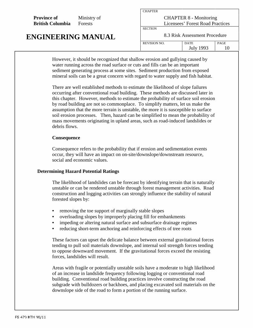
)6�����+7+������
CHAPTER
Province of Ministry ofBritish Columbia Forests
CHAPTER 8 - MonitoringLicensees’ Forest Road Practices
SECTION
ENGINEERING MANUAL 8.3 Risk Assessment Procedure
REVISION NO. DATE PAGE
July 1993 10
However, it should be recognized that shallow erosion and gullying caused bywater running across the road surface or cuts and fills can be an importantsediment generating process at some sites. Sediment production from exposedmineral soils can be a great concern with regard to water supply and fish habitat.
There are well established methods to estimate the likelihood of slope failuresoccurring after conventional road building. These methods are discussed later inthis chapter. However, methods to estimate the probability of surface soil erosionby road building are not so commonplace. To simplify matters, let us make theassumption that the more terrain is unstable, the more it is susceptible to surfacesoil erosion processes. Then, hazard can be simplified to mean the probability ofmass movements originating in upland areas, such as road-induced landslides ordebris flows.
Consequence
Consequence refers to the probability that if erosion and sedimentation eventsoccur, they will have an impact on on-site/downslope/downstream resource,social and economic values.
Determining Hazard Potential Ratings
The likelihood of landslides can be forecast by identifying terrain that is naturallyunstable or can be rendered unstable through forest management activities. Roadconstruction and logging activities can strongly influence the stability of naturalforested slopes by:
• removing the toe support of marginally stable slopes• overloading slopes by improperly placing fill for embankments• impeding or altering natural surface and subsurface drainage regimes• reducing short-term anchoring and reinforcing effects of tree roots
These factors can upset the delicate balance between external gravitational forcestending to pull soil materials downslope, and internal soil strength forces tendingto oppose downward movement. If the gravitational forces exceed the resistingforces, landslides will result.
Areas with fragile or potentially unstable soils have a moderate to high likelihoodof an increase in landslide frequency following logging or conventional roadbuilding. Conventional road building practices involve constructing the roadsubgrade with bulldozers or backhoes, and placing excavated soil materials on thedownslope side of the road to form a portion of the running surface.
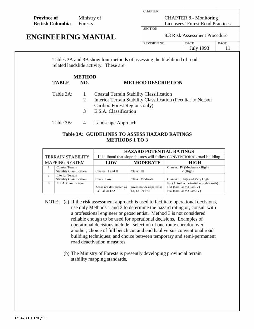
)6�����+7+������
CHAPTER
Province of Ministry ofBritish Columbia Forests
CHAPTER 8 - MonitoringLicensees’ Forest Road Practices
SECTION
ENGINEERING MANUAL 8.3 Risk Assessment Procedure
REVISION NO. DATE PAGE
July 1993 11
Tables 3A and 3B show four methods of assessing the likelihood of road-related landslide activity. These are:
METHODTABLE NO. METHOD DESCRIPTION
Table 3A: 1 Coastal Terrain Stability Classification2 Interior Terrain Stability Classification (Peculiar to Nelson
Cariboo Forest Regions only)3 E.S.A. Classification
Table 3B: 4 Landscape Approach
Table 3A: GUIDELINES TO ASSESS HAZARD RATINGSMETHODS 1 TO 3
HAZARD POTENTIAL RATINGSTERRAIN STABILITY Likelihood that slope failures will follow CONVENTIONAL road-building
MAPPING SYSTEM LOW MODERATE HIGH1 Coastal Terrain
Stability Classification Classes: I and II Class: IIIClasses: IV (Moderate - High)
V (High)2 Interior Terrain
Stability Classification Class: Low Class: Moderate Classes: High and Very High3 E.S.A. Classification
Areas not designated asEs, Es1 or Es2
Areas not designated asEs, Es1 or Es2
Es (Actual or potential unstable soils)Es1 (Similar to Class V)Es2 (Similar to Class IV)
NOTE: (a) If the risk assessment approach is used to facilitate operational decisions,use only Methods 1 and 2 to determine the hazard rating or, consult witha professional engineer or geoscientist. Method 3 is not consideredreliable enough to be used for operational decisions. Examples ofoperational decisions include: selection of one route corridor overanother; choice of full bench cut and end haul versus conventional roadbuilding techniques; and choice between temporary and semi-permanentroad deactivation measures.
(b) The Ministry of Forests is presently developing provincial terrainstability mapping standards.
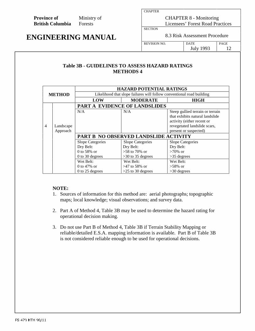
)6�����+7+������
CHAPTER
Province of Ministry ofBritish Columbia Forests
CHAPTER 8 - MonitoringLicensees’ Forest Road Practices
SECTION
ENGINEERING MANUAL 8.3 Risk Assessment Procedure
REVISION NO. DATE PAGE
July 1993 12
Table 3B - GUIDELINES TO ASSESS HAZARD RATINGSMETHODS 4
HAZARD POTENTIAL RATINGSMETHOD Likelihood that slope failures will follow conventional road building
LOW MODERATE HIGHPART A EVIDENCE OF LANDSLIDES
4 LandscapeApproach
N/A N/A Steep gullied terrain or terrainthat exhibits natural landslideactivity (either recent orrevegetated landslide scars,present or suspected)
PART B NO OBSERVED LANDSLIDE ACTIVITYSlope CategoriesDry Belt:0 to 58% or0 to 30 degrees
Slope CategoriesDry Belt:>58 to 70% or>30 to 35 degrees
Slope CategoriesDry Belt:>70% or>35 degrees
Wet Belt:0 to 47% or0 to 25 degrees
Wet Belt:>47 to 58% or>25 to 30 degrees
Wet Belt:>58% or>30 degrees
NOTE:1. Sources of information for this method are: aerial photographs; topographic
maps; local knowledge; visual observations; and survey data.
2. Part A of Method 4, Table 3B may be used to determine the hazard rating foroperational decision making.
3. Do not use Part B of Method 4, Table 3B if Terrain Stability Mapping orreliable/detailed E.S.A. mapping information is available. Part B of Table 3Bis not considered reliable enough to be used for operational decisions.

)6�����+7+������
CHAPTER
Province of Ministry ofBritish Columbia Forests
CHAPTER 8 - MonitoringLicensees’ Forest Road Practices
SECTION
ENGINEERING MANUAL 8.3 Risk Assessment Procedure
REVISION NO. DATE PAGE
July 1993 13
Rate the likelihood of road-related landslide activity using the following scale:
Low Hazard Potential: LowModerate Hazard Potential: Mod.High Hazard Potential: High
To evaluate risk to values from landslide and sedimentation hazards, a third factorneeds to be considered in addition to the consequence rating and the likelihood oflandslide hazard. This third factor is sediment deliverability, or the likelihood ofsediment from a landslide reaching on-site/downslope/downstream values (see 5thstep of risk assessment procedures).
The length of the runout zone of potential road-related landslides is an importantconsideration. If the likelihood is high that sediment from potential road-relatedlandslide occurrences will reach values such as water supply, fish habitat,life/property/transportation or utilities, do not adjust the risk rating determined inthe 4th step of the risk rating procedure. If the likelihood of sedimentdeliverability is low for these four values mentioned, decrease the risk determinedin the 4th step by at least one rating.
The likelihood of sediment deliverability may be determined often from terrainstability maps. When included, these maps have landslide runout distancesymbols on each terrain polygon.
Where terrain stability maps are not available, or if runout distance symbols arenot included on polygons, adopt the following rationale for establishing risk forpurposes of prioritizing monitoring activities:
• Where streams, highways and other roads, railways, residential or commercialdevelopments, or utilities are separated from the toe of steep slopes by a flatbench or terrace (e.g. at least 200 m from a slope less than 20 degrees),decrease the risk by at least one rating.
• If no such separation exists, do not adjust the risk rating.
Where there is some question about the length of the runout zone of potentialroad-related landslides, consult with a specialist.
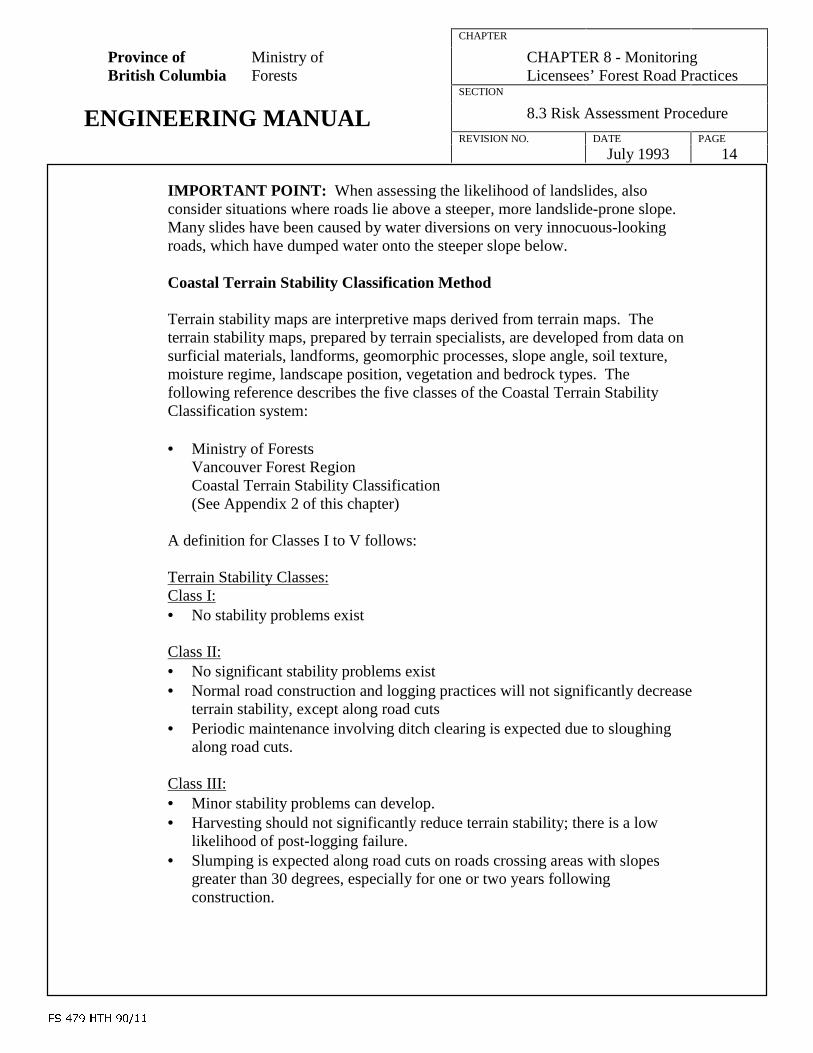
)6�����+7+������
CHAPTER
Province of Ministry ofBritish Columbia Forests
CHAPTER 8 - MonitoringLicensees’ Forest Road Practices
SECTION
ENGINEERING MANUAL 8.3 Risk Assessment Procedure
REVISION NO. DATE PAGE
July 1993 14
IMPORTANT POINT: When assessing the likelihood of landslides, alsoconsider situations where roads lie above a steeper, more landslide-prone slope.Many slides have been caused by water diversions on very innocuous-lookingroads, which have dumped water onto the steeper slope below.
Coastal Terrain Stability Classification Method
Terrain stability maps are interpretive maps derived from terrain maps. Theterrain stability maps, prepared by terrain specialists, are developed from data onsurficial materials, landforms, geomorphic processes, slope angle, soil texture,moisture regime, landscape position, vegetation and bedrock types. Thefollowing reference describes the five classes of the Coastal Terrain StabilityClassification system:
• Ministry of ForestsVancouver Forest RegionCoastal Terrain Stability Classification(See Appendix 2 of this chapter)
A definition for Classes I to V follows:
Terrain Stability Classes:Class I:• No stability problems exist
Class II:• No significant stability problems exist• Normal road construction and logging practices will not significantly decrease
terrain stability, except along road cuts• Periodic maintenance involving ditch clearing is expected due to sloughing
along road cuts.
Class III:• Minor stability problems can develop.• Harvesting should not significantly reduce terrain stability; there is a low
likelihood of post-logging failure.• Slumping is expected along road cuts on roads crossing areas with slopes
greater than 30 degrees, especially for one or two years followingconstruction.

)6�����+7+������
CHAPTER
Province of Ministry ofBritish Columbia Forests
CHAPTER 8 - MonitoringLicensees’ Forest Road Practices
SECTION
ENGINEERING MANUAL 8.3 Risk Assessment Procedure
REVISION NO. DATE PAGE
July 1993 15
Class IV:• Expected to contain areas where there is a moderate to high likelihood of
slope failures following conventional road construction. Wet periodconstruction will significantly increase the potential for slope failure.
• There is a moderate likelihood of failure in logged areas.• A specialist should inspect these areas prior to any development in order to
assess in detail the stability of the affected area.
Class V:• Contain areas of natural instability.• There is a high likelihood that slope failure will follow logging or
conventional road building.• A specialist should inspect these areas prior to development in order to assess
in detail the stability of the affected area.
The five class terrain stability system only flags the likelihood for any landslide tooccur. It does not provide the expected size or frequency of landslide failures.For example, a Class V polygon on the east side of Vancouver Island mayexperience 1 slide/100 hectares/10 years, while a Class V on the west coast of theQueen Charlottes will experience about 10 slides/100 hectares/10 years. Toaddress this, the risk to values within areas of very high frequency of intenserainfall (e.g. west and north coast of Vancouver Island, west coast Charlottes,mid-coast, Mission-Hope area, etc.) should be increased by at least one rating (see6th step of risk rating procedure).
Interior Terrain Stability Classification Method
Nelson and Cariboo Forest Regions have in the past used a different terrainstability classification system than the Coast. The Nelson and Cariboo ForestRegions use a low, moderate, high and very high (or extreme) system. It isexpected that provincial terrain stability mapping standards, which are currentlybeing developed, will adopt only the Five Class Terrain Stability ClassificationSystem for the whole province.
The very high and high classes used in the Nelson and Cariboo Regions arecomparable to the V and IV classes used on the Coast. The following referencesprovide some additional information on the Interior Terrain Stability classes:
• Ministry of Forests, Developing Timber Harvesting Prescriptions to MinimizeSite Degradation - Interior Sites, Land Management Handbook No. 62

)6�����+7+������
CHAPTER
Province of Ministry ofBritish Columbia Forests
CHAPTER 8 - MonitoringLicensees’ Forest Road Practices
SECTION
ENGINEERING MANUAL 8.3 Risk Assessment Procedure
REVISION NO. DATE PAGE
July 1993 16
E.S.A. Classification Method:
Environmentally sensitive areas (E.S.A.) are identified and delineated during aforest inventory through photo interpretation, ground investigation, low-levelhelicopter flights, and data provided by other resource agencies and public interestgroups. The E.S.A. classification system recognizes these E.S.A. categories: soil(Es), forest regeneration (Ep), snow avalanche (Ea), recreation (Er), wildlife(Ew), water (Eh), and fisheries (fisheries symbols).
Except for Tree Farm Licence (TFL) areas and private land, forest inventory mapinformation exists for all areas of the province. Inventory Branch is responsiblefor collecting and updating the information.
The following references provide details on each E.S.A. Category:
• Ministry of ForestsVancouver Forest RegionMemo April 7, 1992File: 870-3 (See Appendix 1 of this chapter)
• Ministry of ForestsInventory ManualVolume 1, Chapter 2
For the soil (Es) category, and most other categories, two E.S.A. classes arerecognized: high and moderate. These are denoted by the subscripts 1 and 2,respectively (Es1 and Es2).
Definitions for Es1 and Es2 classes are:
Soil Sensitivity (Stability) Class Definitions:Es1:• It is highly likely that landslides will follow logging or conventional road
construction.Es2• Expected to contain areas where there is moderate likelihood of landslides
following logging and a moderate to high likelihood of landslides followingconventional road construction.
For consistency, the Es1 and Es2 categories are roughly equivalent, but morecrudely mapped, to the Class V and IV categories, respectively, of the Five ClassTerrain Stability Classification System. This five class system is in widespreaduse on the B.C. coast.
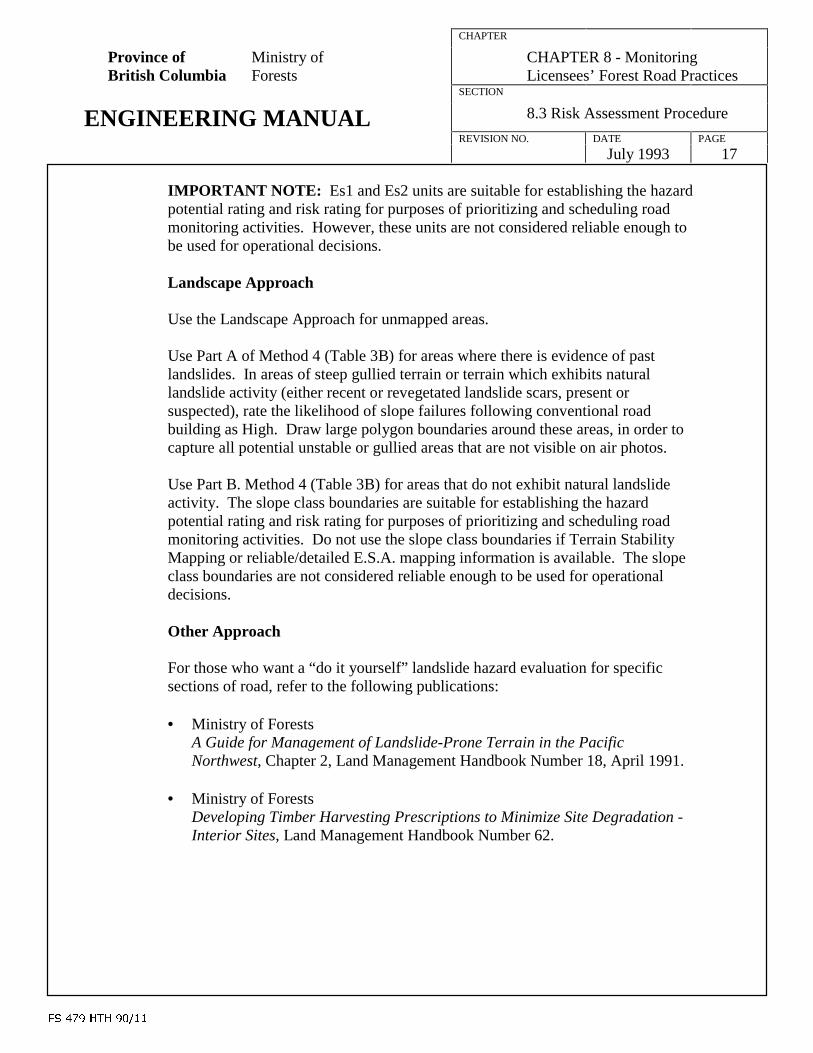
)6�����+7+������
CHAPTER
Province of Ministry ofBritish Columbia Forests
CHAPTER 8 - MonitoringLicensees’ Forest Road Practices
SECTION
ENGINEERING MANUAL 8.3 Risk Assessment Procedure
REVISION NO. DATE PAGE
July 1993 17
IMPORTANT NOTE: Es1 and Es2 units are suitable for establishing the hazardpotential rating and risk rating for purposes of prioritizing and scheduling roadmonitoring activities. However, these units are not considered reliable enough tobe used for operational decisions.
Landscape Approach
Use the Landscape Approach for unmapped areas.
Use Part A of Method 4 (Table 3B) for areas where there is evidence of pastlandslides. In areas of steep gullied terrain or terrain which exhibits naturallandslide activity (either recent or revegetated landslide scars, present orsuspected), rate the likelihood of slope failures following conventional roadbuilding as High. Draw large polygon boundaries around these areas, in order tocapture all potential unstable or gullied areas that are not visible on air photos.
Use Part B. Method 4 (Table 3B) for areas that do not exhibit natural landslideactivity. The slope class boundaries are suitable for establishing the hazardpotential rating and risk rating for purposes of prioritizing and scheduling roadmonitoring activities. Do not use the slope class boundaries if Terrain StabilityMapping or reliable/detailed E.S.A. mapping information is available. The slopeclass boundaries are not considered reliable enough to be used for operationaldecisions.
Other Approach
For those who want a “do it yourself” landslide hazard evaluation for specificsections of road, refer to the following publications:
• Ministry of ForestsA Guide for Management of Landslide-Prone Terrain in the PacificNorthwest, Chapter 2, Land Management Handbook Number 18, April 1991.
• Ministry of ForestsDeveloping Timber Harvesting Prescriptions to Minimize Site Degradation -Interior Sites, Land Management Handbook Number 62.

)6�����+7+������
CHAPTER
Province of Ministry ofBritish Columbia Forests
CHAPTER 8 - MonitoringLicensees’ Forest Road Practices
SECTION
ENGINEERING MANUAL 8.3 Risk Assessment Procedure
REVISION NO. DATE PAGE
July 1993 18
Determining Consequence Ratings
Hazards such as landslides, surface soil erosion and sedimentation can imposehigh economic, environmental and social consequences. The values that may beaffected by erosion and sedimentation include:
On-Site/Downslope/Downstream Resource Values
• water quality and supply• fish habitat• wildlife habitat and migration• forest site productivity
On-Site/Downslope Social and Economic Values
• human life; private property or equipment; downslope railways, highways andother roads
• utilities• landscape values• recreation values
Identify the types and sensitivity of social, economic, and forest resource valuesin areas located along a proposed or existing road. There are a number of ways toassess the types and sensitivity of values that may be affected by erosion andsedimentation:
Map Overview
• reviewing the on-site and downslope/downstream areas on the district atlas,forest cover maps and other maps. These maps are typically plotted at1:20,000 scale
Contracting Other Users• contacting other resource agencies, utility companies and local land owners
Local Knowledge• local knowledge and observation through aerial photography overview,
ground traverse, or viewing adjacent development
NOTE: Document local knowledge and observations
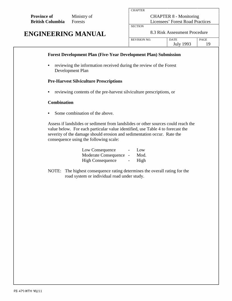
)6�����+7+������
CHAPTER
Province of Ministry ofBritish Columbia Forests
CHAPTER 8 - MonitoringLicensees’ Forest Road Practices
SECTION
ENGINEERING MANUAL 8.3 Risk Assessment Procedure
REVISION NO. DATE PAGE
July 1993 19
Forest Development Plan (Five-Year Development Plan) Submission
• reviewing the information received during the review of the ForestDevelopment Plan
Pre-Harvest Silviculture Prescriptions
• reviewing contents of the pre-harvest silviculture prescriptions, or
Combination
• Some combination of the above.
Assess if landslides or sediment from landslides or other sources could reach thevalue below. For each particular value identified, use Table 4 to forecast theseverity of the damage should erosion and sedimentation occur. Rate theconsequence using the following scale:
Low Consequence - LowModerate Consequence - Mod.High Consequence - High
NOTE: The highest consequence rating determines the overall rating for theroad system or individual road under study.

TABLE 4: GUIDELINES TO ASSESS CONSEQUENCE RATINGS
ON-SITE DOWNSLOPE/DOWNSTREAMVALUES ADJACENT
CONSEQUENCE (OR SEVERITY) RATINGSForecast the consequence or severity of the damage or loss to a specific value,
should erosion and sedimentation occur
TO ROAD ALIGNMENT LOW MODERATE HIGH
ENVI
WATER SUPPLY Areas not rated asModerate or High
Areas having very high watervalues, but less sensitive thanthose with High ratings (e.g.,Eh2 class areas; individuallicensed domestic use water-shed, licensed irrigation/industrial users)
Areas having very high watervalues which, if damaged, wouldhave a serious long-term effect onwater quality (e.g., Eh1 classareas; all community watersheds;and moderately to heavily licenseddomestic use water-sheds)
RONMEN
FISH HABITAT Areas having low fisheryvalues (e.g., Class IVstream and not tributary toClass I, II or III streams)
Areas having moderatefishery values (e.g., Class IIIstream and not tributary toClass I and II streams)
Areas having high to very highfishery values (e.g., Class I and IIstreams, or Class III and IVstreams with potential to causesedimentation of Class I and IIsteams)
TAL
WILDLIFEHABITAT ANDMIGRATION
Areas not rated asModerate or High
Areas having high wildlifevalues, but less sensitive thanthose with High ratings (e.g.,Ew2 class areas
Areas having critical importanceto wildlife (e.g., Ew1 class areas)
FORESTRY SITEPRODUCTIVITY
Areas not rated asModerate or High
Areas having moderatepotential to growmerchantable timber
Areas having high potential togrow merchantable timber which,if damaged, would have a seriouslong-term effect on regeneration
SOCIA
HUMAN LIFE,PRIVATEPROPERTY,ROADS ANDRAILWAYS
Areas that are uninhabitedand undeveloped, oroccasionally inhabitedterritory and cultivatedfarmland
N/A Areas having rural development,domestic dwellings or industrialdevelopment, highways andrailways
L
A
UTILITIES Areas with no utilities N/A Areas having electric transmissiontowers, gas and oil lines or fibreoptic cable
ND
ECO
LANDSCAPE(VISUAL)FEATURES
Areas having non-visibledevelopment or LowLandscape Sensitivity
Areas having high value forviewing, but less sensitivethan those with High ratings(e.g., Er2 class areas ofMedium LandscapeSensitivity)
Areas having exceptionally highvalue for viewing (e.g., Er1 classareas and areas of High LandscapeSensitivity)
NOMIC
RECREATIONALFEATURES(PHYSICAL,BIOLOGICAL,CULTURAL ORHISTORIC)
Areas absent of, or havinglow, physical, biological,cultural or historic features
Areas having high value forrecreation, but less sensitivethan those with High rating(e.g., Er2 class areas)
Areas having exceptionally highvalue for recreation (e.g., Er1 classareas)
APPENDIX F
Miscellaneous Road Inspection Forms
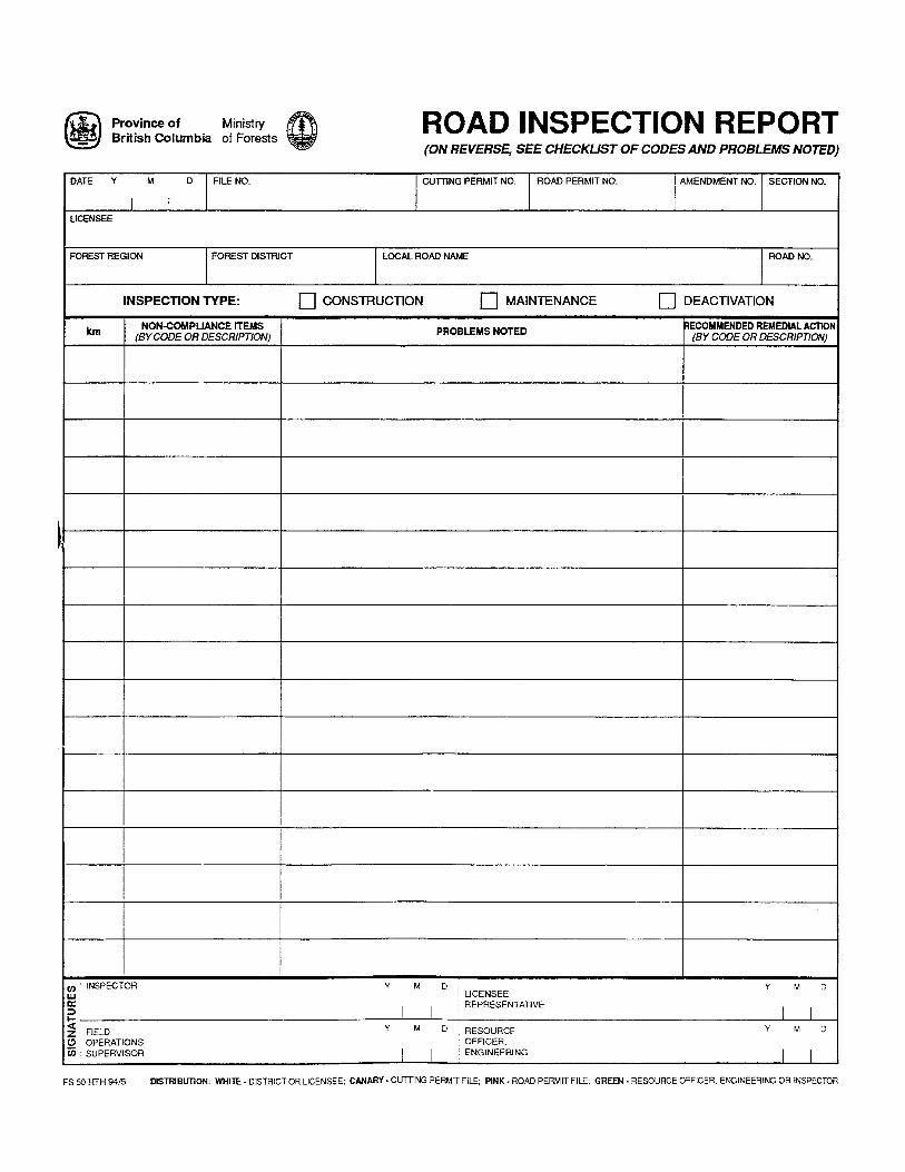


APPENDIX G
British Columbia. B.C. Ministry of Forests and B.C. Ministry of Environment,Lands and Parks (1994). British Columbia Forest Practices CodeStandards. Victoria, British Columbia: B.C. Ministry of Forests andB.C. Ministry of Environment, Lands and Parks, 79-100.
Proposed Forest Practices Standards
9 / Forest road engineering 79
9 Forest road engineering
Guiding principles
• The establishment, maintenance, and deactivation of forestroads should maximize public benefits by optimizing theintegration of identified resource values.
• Planning for road establishment, maintenance, anddeactivation should be carried out within the framework offorest development planning to facilitate coordination withharvesting activities and to simplify public participation andagency referral. Forest development planning should ensurethat roads are planned at least five years into the future over alogical geographic unit.
• Forest road networks should be planned to optimize industrialefficiency and minimize environmental impact whileproviding for user safety. Consistent with these objectives,such networks should avoid unstable or otherwise hazardousterrain, incorporate well-designed and properly placeddrainage structures, and minimize the total length of road for agiven unit.
• Where alternatives exist, stream crossings should beminimized and sensitive areas such as critical wildlife habitat,steep slopes, areas with high-value aesthetic values, andriparian areas should be avoided. Where stream crossingscannot be minimized or sensitive resource areas avoided,mitigating measures or different harvesting methods should beused.
• Roads should be either fully maintained or appropriatelydeactivated in order to provide for user safety, to protect theroad investment, and to minimize any negative effects onresource values. The main concern to be addressed bymaintenance or deactivation activities, after safety ofstructures, should be the prevention of soil erosion and masswasting.

Proposed Forest Practices Standards
9 / Forest road engineering 80
Note: Requirements for forest practices within classified areas andcommunity watersheds are listed at the end of this section.
9.1 Road planning
9.1.1 Access development planning
1 Access development planning must be carried out for all roadconstruction or reconstruction, as part of a Forest DevelopmentPlan or an Access Management Plan, and must identify:• objectives for access development and short- and long- term
forest management goals;• resource values and the effects of the road on those values;• the extent of known hazards and their consequences;• primary route corridors (projections) from the logging areas to
the existing road system;• proposed roads from the logging areas to the existing road
system;• duration and periods of use (seasonal or all-weather) and
anticipated traffic types and volumes;• other known users;• existing roads (including the road network tie-in to the public
road system, processing plant, or log dump) and bridges andmajor culverts (2000 mm diameter or greater);
• proposed and existing log dumps and other log handling andstorage areas;
• private properties; and,• public utilities.
2 Roads must be planned to avoid known hazards. Where it isnecessary to traverse areas with known hazards, those areas mustbe identified so that mitigating measures can be prescribed. Thedistrict manager, in consultation with other appropriate agencies,must approve the areas to be traversed.
3 Duplication of access must be avoided, existing access must beused, and roads must be matched to harvesting methods andresource uses, all to the fullest extent possible.
Field Guides:Under preparation: how to carry out access planning; how toprepare access development information as part of ForestDevelopment Plans or Access Management Plans
Proposed Forest Practices Standards
9 / Forest road engineering 81
9.1.2 Road maintenance planning
1 Road maintenance planning must be carried out annually as partof a Forest Development Plan or an Access Management Plan,for all roads that are in use and have not been deactivated.
2 Road maintenance planning must identify the forest roads to beused each year for forest management, industrial, and otherpurposes, and maintained to:• protect the structural integrity of the road, the structures on the
road, and the cleared area;• minimize the environmental impact; and,• meet user safety requirements.
Field Guides:P1Under preparation: how to prepare maintenance planninginformation as part of Forest Development Plans or AccessManagement Plans.
9.1.3 Road deactivation planning
1 Three-year road deactivation planning must be carried outannually, as part of a Forest Development Plan or AccessManagement Plan, for all roads, including the structures on them,that will no longer be regularly maintained.
2 Road deactivation planning must detail the following:• mapping of roads that are currently deactivated to a temporary
or semi-permanent level;• roads that have been permanently deactivated, by year and
level of deactivation; and,• a list that identifies the roads, level of deactivation by year,
and types of vehicles expected to use each road afterdeactivation.
Field Guides:P1, P2Under preparation: how to prepare deactivation information aspart of Forest Development Plans or Access Management Plans
Proposed Forest Practices Standards
9 / Forest road engineering 82
9.2 Reconnaissance
1 The optimum road location must be selected on the basis of theaccess development planning information.
2 The optimum road location must be marked in the field.
3 Areas that may be prone to mass wasting must be identified sothat mitigating measures can be prescribed where roads areanticipated to traverse these areas.
4 Areas that may be prone to surface soil erosion must beidentified so that mitigating measures can be prescribed whereroads are anticipated to traverse these areas.
5 Roads must be located to protect and maintain identified resourcevalues as specified in landscape level management objectives orhigher-level plans. Road locations that conflict with identifiedresources must be approved by the district manager inconsultation with other appropriate resource agencies.
6 Watercourse crossings must be selected such that channel andbank disturbances can be prevented or mitigated and structuresecurity provided.
7 Road location lines must be tied to references, other controlpoints, and other identified resource data.
Field Guides:Under preparation: how to identify areas prone to masswasting/soil erosion
9.3 Survey
1 A site survey must be carried out for all bridges and for culverts(2000 mm diameter or greater).
Proposed Forest Practices Standards
9 / Forest road engineering 83
Standards:
1 Site surveys must record: Contents of a site survey
• stream/lake class;• high water mark;• streamflow measurements;• description of streambed materials;• streambed gradient;• cross-section and profile of crossing;• date of survey; and,• existing improvements and other known resource values.
2 A location survey to obtain data for detailed road design must becarried out in areas with slopes greater than 50%, in areasidentified as having terrain stability class IV or V slopes, orwhere they are required in higher level plans.
Field Guides:P1, P3Under preparation: how to select an appropriate level of survey
9.4 Roadway design
1 Road widths must be designed to accommodate the intendedvehicle sizes and traffic volume.
2 Clearing widths must be the minimum required to accommodatethe road prism, user safety, subgrade drainage, subgrade stability,spoil areas, equipment operability, snow removal, and fencingand other structures.
3 Road alignment must be designed to provide for user safety byincluding, for example:• turnouts;• traffic controls;• appropriate travel speeds and stopping distance; and• suitable stopping and sight distances at road junctions.
4 Road designs must incorporate measures to mitigate surface soilerosion.

Proposed Forest Practices Standards
9 / Forest road engineering 84
5 A geometric road design must be carried out, based on thelocation survey data in areas with slopes greater than 50% and inareas identified as having terrain stability class IV or V slopes.
6 Fill slope angles must be designed such that they do not exceedthe angle of repose of the soil or rock materials.
7 Cut slope angles must be designed so as to remain stable over theexpected life of the road, unless ravelling or sloughing of the cutbank would not be expected to contribute to slope failures.
Field Guides:P1Under preparation: how to mitigate surface soil erosion
9.5 Drainage design criteria
1 Bridges, culverts, and fords must be designed to maintain naturalsurface drainage patterns.
2 Bridges and culverts must be designed to prevent or mitigatechannel and bank disturbance and to provide structure security.
3 Cross-drain culverts must be spaced and ditches designed toprevent ditch water accumulation and accelerated ditch erosion.
Standards:
1 Unless soil and runoff conditions require increased sizes, Minimum culvert sizes
minimum pipe culvert diameter sizes must be 400 mm eastof the Cascade Mountains and 600 mm west of the CascadeMountains, and minimum opening size for log culvertsmust be 0.5 m in depth and 1.5 m in width.
4 Culvert inlet and outlet protection measures must be designed toprovide protection against erosion and mass wasting.
5 Crossings in fish-bearing waters must be designed to providesafe fish passage.

Proposed Forest Practices Standards
9 / Forest road engineering 85
6 Culverts on all seasonal and continuous watercourses must bedesigned so as not to destabilize the stream channel.
7 Protective measures must be designed to protect the structuralintegrity of culverts where debris cannot safely pass.
8 New bridges, their approaches, and stream culvert structuresmust be designed to meet the peak flow criteria as shown in thefollowing table:
Minimum design peak flow
All stream culverts 100-year return periodPermanent bridges 100-year return periodSemi-permanent bridges 100-year return periodTemporary bridges 50-year return period
However, bridges whose vulnerable components are removed attimes of risk must be designed to pass expected flows for theseasons of use.
9 Design drawings and technical specifications must be preparedfor bridges and major culverts.
10 Full-width decking between curbs must be designed for new andreplacement decks.
Field Guides:P1Under preparation: design of fords and log culverts; culvertsizing and spacing; preparation of design drawings /specifications; culvert design / material selection
9.6 Design by professional engineersand professional geoscientists
1 Where it is necessary to traverse areas identified on terrainhazard mapping as having a terrain stability class IV or V slopes,suitable mitigating measures must be prescribed by aprofessional engineer or professional geoscientist.
2 Cattleguard fabrication, retaining walls, and other specialstructures must be designed by a professional engineer.

Proposed Forest Practices Standards
9 / Forest road engineering 86
3 All bridges and log culverts must be designed by a professionalengineer, except where both of the following conditions apply:• the structures are composed of single-span, temporary log
superstructures on timber cribs or sills, with the superstructuresized from tables or design aids prepared by a professionalengineer; and,
• the designer can show from past experience with similarstructures that the structure is adequate for the given sitecondition.
4 The size and installation of all permanent material culvertshaving a pipe diameter of 2000 mm or greater, or having amaximum design discharge of more than 6 m3/second, must bedesigned by a professional engineer.
5 Professional engineers must design permanent and semi-permanent bridges according to the latest code requirements ofthe Canadian Standards Association for Design of HighwayBridges, CAN/CSA-S6 and the latest version of the CanadianFoundation Engineering Manual. The peculiarities of loggingtruck unbalanced loads and eccentricities must be considered inall bridge design.
Field Guides:P1, P4
9.7 Construction
9.7.1 Clearing
1 All standing trees within the clearing width must be felled.Natural surface drainage patterns must be maintained.
2 Trees must be directionally felled away from watercourses, to thefullest extent possible. Felling and yarding techniques must beselected to prevent streambanks from destabilizing.
3 Danger trees (as defined by the Workers’ Compensation Board)with the potential to reach the proposed road surface must befelled concurrently with clearing operations.
4 All stumps, roots, embedded logs, organics, and other unsuitablesoils within the roadway prism width must be removed, except

Proposed Forest Practices Standards
9 / Forest road engineering 87
those organics outside the road subgrade width portion of theroad on the downhill side, in areas having slopes other thanterrain stability class IV or V slopes, and where downslopeconsequences are rated low.
Note: This Rule does not apply to overlanding or snow roads.Also, potentially unstable slopes must be pulled back when theroad is deactivated.
5 Full bench cuts and end haul must be used on short-term roadsbuilt on areas identified as having terrain stability class IV or Vslopes, unless other measures are designed by a professionalengineer or professional geoscientist.
Note: If stumps and logs are left under or against the fill, the fillslopes must be pulled when the road is semi-permanently orpermanently deactivated.
Field Guides:P1
9.7.2 Slash and debris
1 Slash and debris must be disposed of in an environmentally safemanner, reflecting the visual quality objectives described inlandscape level management objectives or higher level plans.
Standards:
1 Disposal of slash and debris must be carried out by one or Methods for disposing of
more of the following methods, unless otherwise exempted slash and debris
by the district manager in consultation with appropriateagencies:
• Scattering: Excess slash and debris must be pileddownslope of the road shoulder and, except for bufferzones in visually sensitive sites, away from standingtimber. The material must be spread to make snowremoval easier and piles must be breached to permitcontrolled drainage and wildlife passage.
Proposed Forest Practices Standards
9 / Forest road engineering 88
• Pile and burning: Slash and debris must be piled awayfrom standing timber and burned no later than the firstburning season after construction.
• Burying: Slash and debris must be buried between thelower clearing width boundary and the toe of the road,where it conforms with existing ground profiles and doesnot interfere with runoff and natural watercourses.Buried slash must be covered with at least 0.3 m of soil.
• End-hauling: Unsuitable materials must be end-hauledto a designated waste site.
2 Slash and debris must not be deposited in a watercourse ordeposited in a location where such material could reasonably beapproved by the district manager with agreement fromappropriate resource agencies.
Field Guides:P1
9.7.3 Subgrade construction
1 Temporary or permanent drainage systems must be builtconcurrently with subgrade construction and must be fullyfunctional.
2 Excavated material must not be sidecast on slopes identified asbeing terrain stability class IV or V, unless the sidecasting hasbeen prescribed by a professional engineer or professionalgeoscientist.
3 If there is an approved prescription prepared by a professionalengineer or professional geoscientist, the road must beconstructed according to that prescription and, where so specifiedin the approved prescription, the resulting construction workmust be certified by a professional engineer or professionalgeoscientist as being in general conformance with the approvedprescription.
4 Roads that have been designed to incorporate measures tomitigate surface soil erosion must be constructed according tothose design measures.

Proposed Forest Practices Standards
9 / Forest road engineering 89
5 In rock work, only rock drilling and blasting techniques thatminimize flyrock and reduce the potential for landslides or slopeinstability must be used. The scheduling and procedures forblasting must accommodate other identified resources andexisting improvements.
6 Borrow pits, quarries, waste areas, and end-haul disposal sitesmust be located on sites where eroded soil materials or otherdeleterious materials can be prevented from enteringwatercourses. These site must be left in a stable condition and avisually acceptable state.
7 The construction site must be kept clean of deleterioussubstances.
8 Construction surveys must be used to control constructionoperations in areas identified as having terrain stability class IVor V slopes.
Standards:
1 Construction surveys must ensure that design specifications Required survey activities
are met. These surveys must include:• marking of the clearing width boundaries;• re-establishment of the road centreline;• grade staking; and,• centreline relocations and redesigns, as needed to
accommodate unforeseen site conditions.
9 Ground disturbance must be minimized during snow roadconstruction through the use of clean compacted snow and ice asfill material.
10 Roads must be constructed in general conformance to theapproved layout and design. To deal with previously unforeseenground conditions, modifications that may adversely impactother resources must be approved by the district manager beforecontinuing with construction.
11 Roads must be constructed so that the road surface is above thewater table during the operating period.
Proposed Forest Practices Standards
9 / Forest road engineering 90
12 Unprotected erodible fill material must not be placed below thehigh water level of adjacent watercourses, whether thesewatercourses are continuous or seasonal.
13 Construction equipment must not be serviced adjacent to, orwashed in, watercourses.
14 Equipment crossings must be limited to one location on a stream,for each road crossing of the stream. Otherwise the districtmanager, in consultation with other agencies, must approve anyadditional equipment crossing locations.
Field Guides:P1, P5Under preparation: road construction specifications; controlledrock blasting/blasting specifications
9.7.4 Drainage
1 Bridges, culverts, fords, and ditches must be constructed tomaintain natural drainage patterns.
2 Bridges, culverts, or fords must be installed at all crossings ofpermanent or seasonal watercourses.
3 Drainage systems must be provided to intercept sidehill drainage,drain ditches, control ditch erosion, prevent ponding of waterwhere instability may occur, prevent water from being directedonto sensitive soils, or prevent deleterious materials from beingdeposited directly into watercourses.
4 Stream and cross-drain culverts must be constructed to ensurethey are structurally sound, functional, and stable.
Standards:
1 All culverts must have a depth of fill cover as required by Required depth of fill
manufacturers’ specifications, but at least 300 mm. cover for culverts
5 Road embankment and waste materials must be prevented fromencroaching on culvert inlets and outlets.

Proposed Forest Practices Standards
9 / Forest road engineering 91
6 Unstable or erodible fill at culvert outlets must be protected witherosion-resistant materials or drainage structures.
7 Bridges and culverts must be constructed to prevent or mitigatestreambank disturbance and to protect downstream water quality.
8 Crossings in fish-bearing streams must be constructed at a timeand in a way that provide safe fish passage and protect fish andfish habitat.
Standards:
1 A fish salvage plan, approved by a designated B.C. Fish salvage plan
Environment official, must be in place where any in-stream work has the potential to temporarily strand fish,and required fish salvage must be implemented accordingto the approved plan.
2 Ice/snow bridges must be removed before snowmelt freshet Ice/snow bridge removal
and, on fish-bearing streams, must provide for fish passage.The district manager, in consultation with appropriateresource agencies, may permit such bridges to be left inplace during the snowmelt freshet.
9 Once construction of those bridges and major culverts requiringprofessional design is completed, a professional engineer mustcertify that the entire structure is in general conformance with thedesign drawings and specifications and is at least as durable andas strong as the original design intended.
10 Ditch blocks must be installed immediately downstream of allcross-drain culvert inlets, except where ditch water converges atthe culvert inlet.
Standards:
1 Ditch blocks, made up of material resistant to erosion or Installation requirements
displacement by ditch flows, must be installed such thattheir crests are between the top of the culvert and 150 mmbelow the adjacent road surface.
Proposed Forest Practices Standards
9 / Forest road engineering 92
11 Geotextile filter fabrics must be used to prevent migration offines on gravel surface log stringer bridges and log culverts.
12 Catch basin or other sediment control devices must beconstructed adjacent to the inlet of cross-drain culverts wheresedimentation may adversely affect downslope resources.
13 Fords and approaches must be composed or constructed oferosion-resistant materials capable of withstanding the intendedtraffic.
14 All permanent bridge and culvert materials must be fabricatedaccording to standards of the Canadian Standards Association.
15 Pile driving records and, for new materials, mill test certificates,in-plant steel fabrication drawings, concrete test results,compaction results, and other pertinent field and constructiondata must be obtained and kept. As-built drawings must beprepared and kept.
Standards:
1 An as-built set of drawings must be prepared, reflecting all Requirements for as-built
changes made during construction. For structures designed drawings
by a professional engineer, the as-built drawings must besealed by an inspecting professional engineer. In addition,the certification of construction must be kept on file.
Field Guides:P1, P6Under preparation: construction of fords and log culverts;processes related to ditch drainage
9.7.5 Road surfacing
1 Road surfacing materials must be applied where, except atbreakup, the subgrade material cannot carry the design wheelloads or where erosion of the subgrade material may adverselyaffect adjacent watercourses.
Proposed Forest Practices Standards
9 / Forest road engineering 93
Field Guides:Under preparation: guidelines for capping road surfaces tominimize surface erosion in sensitive areas
9.7.6 Revegetation
1 Seed must be applied to all exposed soil that will supportvegetation in the first growing season after construction, and thesoil must be revegetated within two years of road construction.The areas to be treated this way are:• inactive borrow pits;• waste areas;• road cuts;• fill slopes; and,• other disturbed areas within the cleared width.
The district manager, in consultation with appropriate resourceagencies, may vary the time requirement.
Field Guides:Under preparation: revegetation prescriptions for exposed roadsoils
9.8 Maintenance
9.8.1 Bridge and major culvert inspection,evaluation, and maintenance
1 All temporary and semi-permanent bridges and major culvertsmust be inspected by qualified inspectors at least once every twoyears and permanent bridges at least once every three years, orafter unusually heavy floods or other unexpected events that arelikely to damage the structures. More frequent inspections mustbe carried out where structural defects are evident. Records ofinspection, noting the general condition of all components, mustbe kept.
Standards:
1 Bridge and major culvert inspections must record: Contents of bridge and• condition of components; culvert inspections
• recommendation for repairs;• date of inspection;• next inspection date; and,• schedule for repairs.
Proposed Forest Practices Standards
9 / Forest road engineering 94
2 If, as a result of inspection by a qualified inspector, a bridge issuspected of having structural deficiencies, a professionalengineer must evaluate the bridge according to the latest coderequirements of the Canadian Standards Association for Designof Highway Bridges, CAN/CSA-S6.
3 Any deficiencies that put road users or the environment at riskmust be corrected. Otherwise, the structure must be closed,restricted to traffic, or removed.
4 Where a professional engineer has determined that a bridge isunable to carry its original design load, a sign must be placed oneach bridge approach stating the actual capacity of the bridge.
9.8.2 Road inspection and maintenance
1 Roads must be inspected and maintained to:• protect the structural integrity of the road prism and cleared
area;• keep the drainage systems functional;• minimize sediment production and the effects on other
resources; and,• meet user safety requirements.
2 Road maintenance inspections must be carried out at frequenciescommensurate with the risk to the road, its users, and adjacentresources, and must assess the adequacy of ditches and culverts,the requirements for improved drainage works or road surfacingor revegetation, and other elements of road integrity and safety.
3 Maintenance work must be carried out according to the approvedForest Development Plan or Access Management Plan.
Standards:
1 Maintenance must be carried out as described in the Required maintenance
approved Forest Development Plan or Access Management activities
Plan, including:• providing vegetation control to provide safe travel, sight
distance, and unobstructed ditches;• cleaning and grading ditches;

Proposed Forest Practices Standards
9 / Forest road engineering 95
• cleaning and repairing culverts and ancillary drainageworks; and
• maintaining and repairing road surfaces and subgradesand bridge and other structure components.
4 Remedial works identified by inspections must be carried outwithin a period of time that is commensurate with the risk to theroad, its users, and the environment.
5 Roads must be maintained until the road is deactivated accordingto the approved Forest Development Plan or AccessManagement Plan.
Field Guides:P1, P6, P7Under preparation: road inspection frequencies,reports/checklists; suitable levels of maintenance
9.9 Deactivation
1 Roads must be deactivated, according to the approved ForestDevelopment Plan or Access Management Plan, when they areno longer in regular use and are not being maintained, such thatthe roadway prism and cleared width are stabilized and thenatural drainage is restored or maintained.
2 Integrated resource management objectives and ongoing andfuture vehicle access requirements must be incorporated intodeactivation planning.
3 The extent of deactivation must be commensurate with the periodof time that regular use of the road is to be suspended, and withthe risk to other resources.
4 Information must be posted to advise road users of hazards thatmay be expected due to deactivation.

Proposed Forest Practices Standards
9 / Forest road engineering 96
5 Prescriptions for deactivation work must be submitted andapproved before work begins. A professional engineer orprofessional geoscientist must prepare a prescription fordeactivation work in areas that may be prone to mass wastingand, where so specified in the prescription, must certify that thedeactivation work was carried out in conformance to theprescription.
6 Site-specific measures must be applied to reduce erosion andmust be consistent with the processes described below:
Temporary (seasonal) deactivation: Temporary deactivationmust be used for roads whose regular use is to be suspended forup to three years.
• Windrows on the outer edge of the road surface must beremoved or breached.
• Inspections must be carried out at frequencies commensuratewith the risk to the road, its users, and adjacent resources, toassess the adequacy of ditches and culverts and therequirements for improved drainage works, road surfacing, orrevegetation.
• Remedial works identified by inspections must be carried outwithin a period of time that is commensurate with the risk tothe road, its users, and the environment.
• Bridges must be repaired or removed, as necessary.• Waterbars or cross-ditches must be constructed along the road
or the road must be insloped or outsloped, as appropriate,where there is a risk of adversely impacting the road and otherresources through erosion, to prevent excessive flowaccumulating and channeling down the road surface.
Semi-permanent deactivation: Semi-permanent deactivationmust be used where regular use is suspended for up to three yearson: winter roads, roads with a potential for debris torrents, andthose roads in particularly isolated areas, as well as on roads inareas where harvesting is suspended until the next pass.• For areas with slopes greater than 50% and areas identified as
having terrain stability class IV or V slopes, the natural flowpatterns must be restored through the removal of all existingstream culverts, the restoration of channel stability, and theinstallation of fords, where possible, if access is requiredduring the period of deactivation. Alternatively, streamculverts must be backed up with similarly sized cross-ditcheson the downhill side.

Proposed Forest Practices Standards
9 / Forest road engineering 97
• For areas with slopes greater than 50% and areas identified ashaving terrain stability class IV or V slopes, all cross-drainculverts must be removed and replaced with cross-ditches, andditch blocks must be intact. Alternatively, cross-drain culvertsmust be backed up with similarly sized cross-ditches on thedownhill side.
• Additional cross-ditches must be constructed where there aresteep grades, heavy ground water seepage, or switchbacks androad junctions, and where ditches are prone to plugging.
• Where overflow of the stream channel is expected, streamculvert excavations must be backed up with a cross-ditch onthe downhill side.
• Temporary and semi-permanent bridges must be removed or,if the bridges are to be left in service, must be repaired orreplaced, as necessary, to protect users during the period ofdeactivation.
• Windrows on the road surface must be removed or breached.• The road surface must be outsloped or insloped, as
appropriate.• Sidecast fill must be pulled back onto the outsloped road grade
to ensure drainage where there is a high risk of slope failure orwhere stability of the fill is questionable. Fill material placedagainst the cut slope must not exceed its angle of repose.
• Cross-ditches must be installed where the ditchline ends.• Exposed soil surfaces must be revegetated.
Permanent deactivation: Permanent deactivation must be usedfor roads to be closed permanently.• The natural flow patterns must be restored through the removal
of all existing stream culverts and the restoration of channelstability.
• Where overflow of the stream channel is expected, streamculvert excavations must be backed up with a cross-ditch onthe downhill side.
• All cross-drain culverts must be removed and replaced withcross-ditches, and ditch blocks must be intact.
• Additional cross-ditches must be constructed where there aresteep grades, where there is heavy ground water seepage,where switchbacks and road junctions are located, and whereditches are prone to plugging.
• All bridge superstructures must be removed. Substructuresmust be removed where failure will affect downstream values.
• Windrows on the road surface must be removed.• The road surface must be outsloped or insloped, as
appropriate.
Proposed Forest Practices Standards
9 / Forest road engineering 98
• Sidecast fill must be pulled back onto the outsloped road gradeto ensure drainage where there is a high risk of slope failure orwhere stability of the fill is questionable. Fill material placedagainst the cut slope must not exceed its angle or repose.
• Cross-ditches must be installed where the ditchline ends.• Deactivation measures must be carried out to increase site
productivity on reception sites and must include, but not belimited to, decompaction of the soils within the road prism,revegetation of exposed soil surfaces, and reforestation.
Field Guides:Under preparation: guidelines for monitoring/tracking ofdeactivated roads
9.10 Classified areas
Note: For a complete list of Standards, see Section 3.4, Classifiedareas.
Riparian management areas
Standards:
1 The tracks or wheels of ground-based machinery such as Equipment-related
bulldozers, skidders, and excavators are not permitted restrictions in the RMA
within 5 m of the streambank (as measured from the edgesof the stream channel), unless at a designated crossing siteor as required for habitat restoration work.
2 Equipment, other than that which is hand-held, must not befueled or serviced within a riparian management area,unless otherwise approved by the district manager.
3 On class A steams, fill heights above culverts measured at Culvert installation and
the road centre-line must not exceed 4 m unless protective design
measures are designed by a professional engineer.
4 Riparian management areas must be marked in the field Marking of the RMA
before any road operations are conducted that could affectthose areas.

Proposed Forest Practices Standards
9 / Forest road engineering 99
5 Gravel or fill material must not be removed within riparian Restriction on gravel
management areas, unless approved in advance by the removal
district manager in consultation with appropriate agencies.
6 Bridge or culvert material storage and equipment Storage and equipment
turnaround sites must be provided outside riparian turnaround sites
management areas, where the normal cleared width cannotaccommodate such sites.
9.11 Community watersheds
Note: For a complete list of Standards, see Section 3.5, Communitywatersheds.
Standards:
1 Where road construction work will proceed after snowfall, Marking of stream courses
all stream courses must be marked before snowfall so as tobe visible at the time of construction.
2 At least 48 hours before the start of road construction, the Notification before the
road operator or proponent must notify water purveyors and start of construction
appropriate resource agencies of the start date ofconstruction.
3 All road construction materials placed below the high water Restriction on placement
mark of adjacent watercourses must be non-toxic. of construction materials
4 An impermeable absorbent mat must placed under Preventing fluid spills
equipment during servicing, to catch spills of fluids and during equipment servicing
waste materials.
5 Fill heights above culverts measured at the road centre-line Culvert installation and
must not exceed 4 m unless protective measures are design
designed by a professional engineer.
6 Culverts must be designed to pass the 100 year returnperiod instantaneous peak discharge with zero head abovethe top of the culvert inlet, unless a professional engineerhas designed inlet and outlet protection measures.

Proposed Forest Practices Standards
9 / Forest road engineering 100
7 Stripped topsoil or slash and other organic debris must not Keeping water intakes and
be placed within a 100 m radius of a water intake, measured culverts free of organic
above the intake. debris
8 Culverts must be installed in such a way as to enablemaintenance equipment to remove obstacles at the culvertends.
9 Those portions of stream channels upstream of culverts Protection of stream
located outside the cleared width must not be altered unless channels upstream of
a designated B.C. Environment official gives approval to do culverts
so.
10 Within community watesheds, roads that are constructed of Road surfacing requirements
erodible parent material must be surfaced with erosion-resistant, compactible gravel or rock to a minimum depth of150 mm. Otherwise, suitable mitigative measures must bedesigned, approved, and carried out to accomplish theobjectives of surfacing.
11 Road building is not permitted on sites with terrain stability Restriction on road building
class III slopes and a high risk of sediment delivery, or on on unstable slopes
terrain stability class IV or V slopes, unless a detailedassessment and road design by a professional engineer orprofessional geoscientist demonstrate that slope stabilityand water quality impacts can be mitigated.
12 Rock from known acid-generating rock formations must Road construction without
not be used for road construction. acid-generating rock
13 Roads and landings must be located so as to maintain the Springs
infiltration capacity and subsurface flow paths of a springrecharge area
Field Guides:P1K1Under preparation: community watershed guidelines;biodiversity guidelines

APPENDIX H
Document 1: British Columbia. B.C. Ministry of Forests (1992-1993). RoadConstruction, Maintenance and Deactivation Handbook. Burnaby,British Columbia: Engineering, Vancouver Forest Region
Document 2: Weaver, W. E. and D. K. Hagans (1990). Techniques and costs foreffective road closure, Technical Paper #90-1. Arcata, California:Pacific Watershed Associates.

NOTICE
1. Some of the material contained in this binder is still under development.Check with your local Forest Service Office (Resource Officer Engineering)for the most up-to-date version.
____________
2. Comments regarding the material are welcomed for improvement purposes.Contact the Ministry of Forests, Ron Jordens, at 4595 Canada Way, Burnaby,B.C. V5G 4L9, Phone 660-7640, Fax 660-7778 or your local Forest ServiceOffice - Resource Officer Engineering
____________
3. This material is the property of the Ministry of Forests. Contact Dennis Smith,Regional Engineering Officer, 660-7633 if you wish to use any of the material.
January 4, 1993 1

INTRODUCTION
This is NOT a road building course. Rather it is a collection of information thatthe Ministry wishes to show to and discuss with road builders, and those associatedwith roads including Ministry of Forests and other agency staff for the purposes of
minimizing the negative impact of roads.____________
Logging roads can cause damage to forest resourcesand impair water quality.
____________
The Ministry of Forests and the forest industry have a responsibility to minimize the negative impacts of road and logging related activities.
____________
Poor road construction/maintenance and deactivation practicescan cause unnecessary erosion, siltation and landslides.
____________
The Coast Fish/Forestry Guidelines and the new Ministry Roads Standardsset the principles and guidelines for road and logging activities.
____________
Everybody associated with roads within our forests must becompletely familiar with these two important documents.
____________
The material that follows focuses on the practical aspects of road construction,maintenance and deactivation activities covered in these documents.
December 31, 1992 2

COURSEOBJECTIVES
To encourage discussion and solutions of road relatedissues between road builders and government agencies.
____________
To understand the impact of road construction on other resourcesand resource users.
____________
To enable the identification and resolution of road-related problemsbefore they happen.
____________
To promote the understanding of the types and stepsof road deactivation.
____________
To provide knowledge about environmentally safe practicesfor road construction, maintenance and deactivation.
December 31, 1992 3
GENERAL
FOREST ROADS
- All roads built in the forests are reviewed and approved by the Forest Service.Road Permits and Cutting Permits containing specifications authorize theconstruction of roads.
- Roads can be either permanent or temporary.
- Temporary or Permanent roads constructed on side slopes greater than60% require a higher degree of planning and engineering and must havesite specific constraints about sidecasting and drainage control. Thefollowing sketches give some conditions under which forest roads can bebuilt.
December 31, 1992 4

The following series of drawings show the desired results for temporaryand permanent roads in different soils [rock or OM (other material)],
and on different side slopes.
The drawings are generic and are meant to generate ideas, conceptsand options and will not necessarily solve site specific situations.
NOTE THE FOLLOWING ABOUT THE DRAWINGS:
1. Scale is 1:100.
2. The cuts and fills are to scale. Fills contain a 33% swell factor.
3. Distance to the edge of the right-of-way is 3m from top of cut and 3 m from toeof the stump and overburden pile, unless otherwise approved by the ForestService.
For permanent roads, excavate cut slopes to their stable angle of repose.
It is normally the downhill slope on which sidecasted material is to be placed thatrequires our attention.
It is critical that everyone (especially the operator) knows in advance exactlywhat disposal criteria apply for excavated material to each particular sectionof road; if not - ask!
January 4, 1993 5
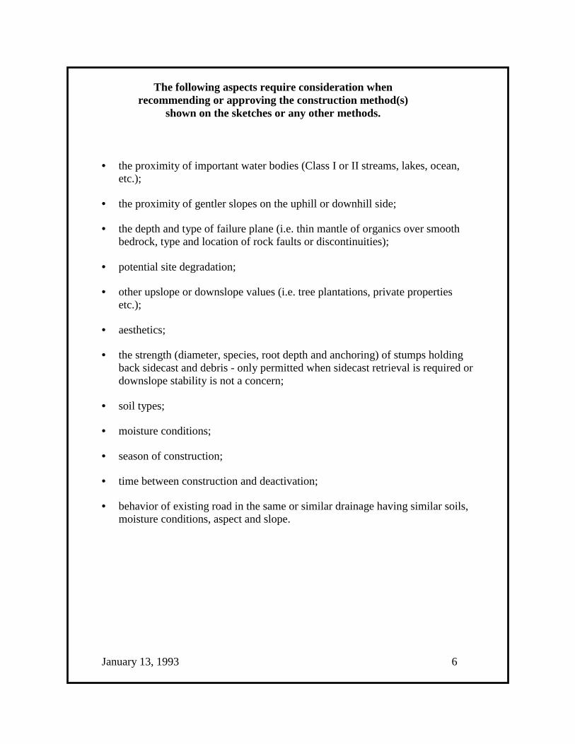
The following aspects require consideration whenrecommending or approving the construction method(s)
shown on the sketches or any other methods.
• the proximity of important water bodies (Class I or II streams, lakes, ocean,etc.);
• the proximity of gentler slopes on the uphill or downhill side;
• the depth and type of failure plane (i.e. thin mantle of organics over smoothbedrock, type and location of rock faults or discontinuities);
• potential site degradation;
• other upslope or downslope values (i.e. tree plantations, private propertiesetc.);
• aesthetics;
• the strength (diameter, species, root depth and anchoring) of stumps holdingback sidecast and debris - only permitted when sidecast retrieval is required ordownslope stability is not a concern;
• soil types;
• moisture conditions;
• season of construction;
• time between construction and deactivation;
• behavior of existing road in the same or similar drainage having similar soils,moisture conditions, aspect and slope.
January 13, 1993 6
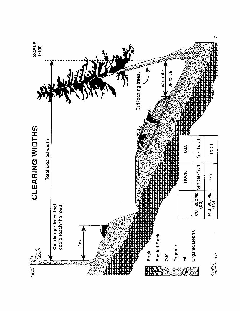

FALLING
Ensure that the clearing width is wide enough to accommodate thenecessary cut and fill slopes and also provide room for debris disposal.
Minimum clearance on cut side is 3 metres - fill side is variable.
____________
Buck logs into length that maximize market value.
____________
Recover any trees that have been felled into standing timber.
____________
Fall any danger trees that may fall or blow down onto the road.
December 31, 1992 8
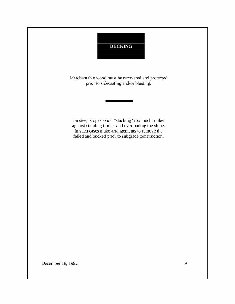
DECKING
Merchantable wood must be recovered and protectedprior to sidecasting and/or blasting.
____________
On steep slopes avoid "stacking" too much timberagainst standing timber and overloading the slope.
In such cases make arrangements to remove thefelled and bucked prior to subgrade construction.
December 18, 1992 9

ROAD WIDTH
Road widths are to be such that they aresafe for use for their intended purpose yet site loss is minimized.
____________
The Ministry standard is 5m ofuseable running surface.
However:
• road widening is necessary for∗ side tracking for curves and∗ turnouts
• narrower roads are encouragedwhenever conditions permit
February 11, 1993 10
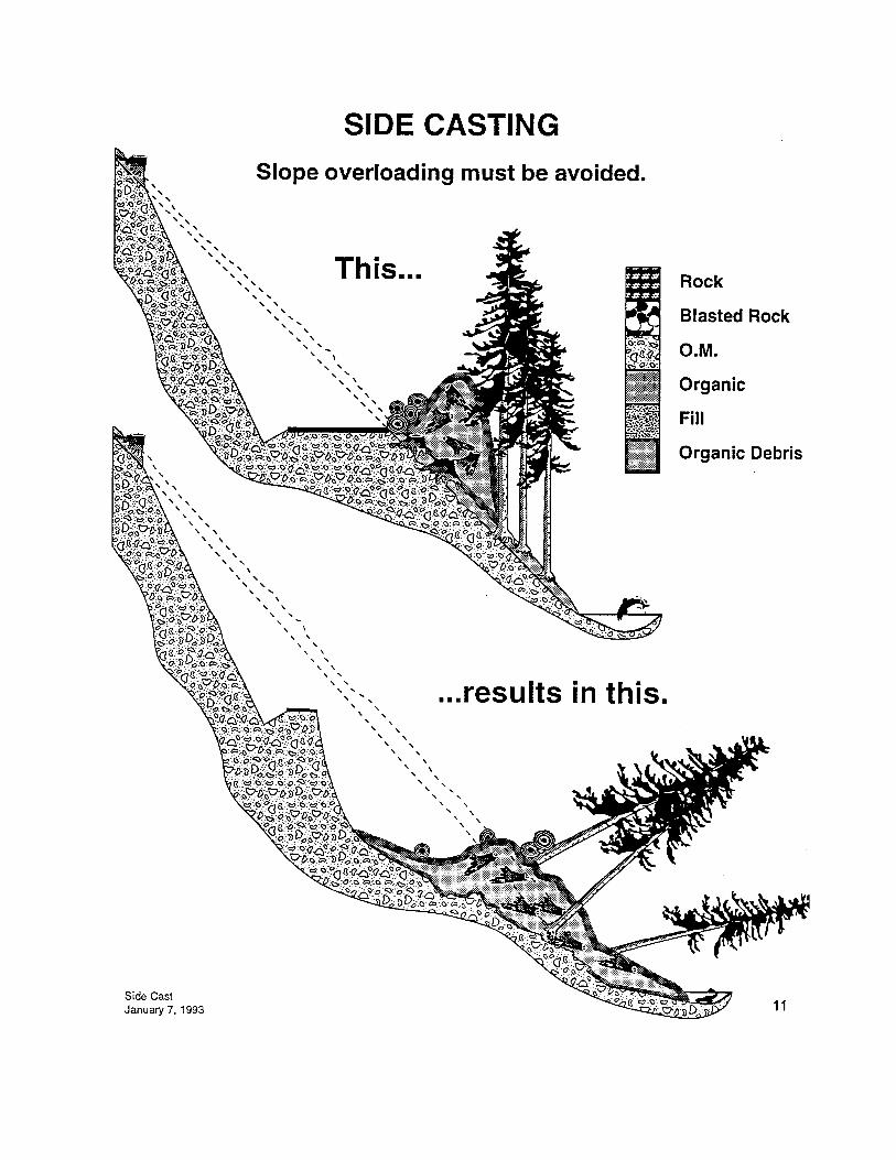
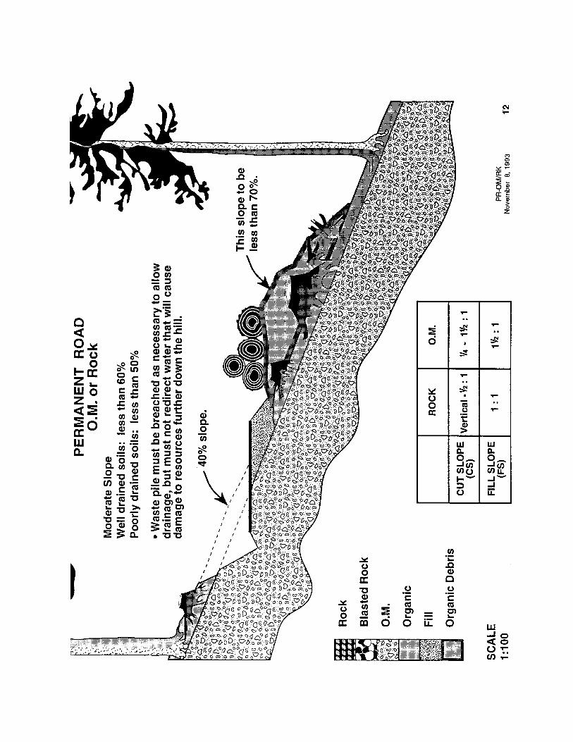
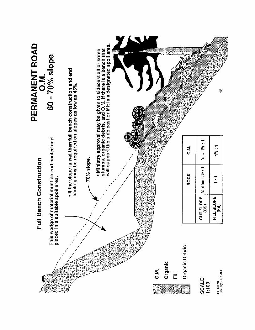
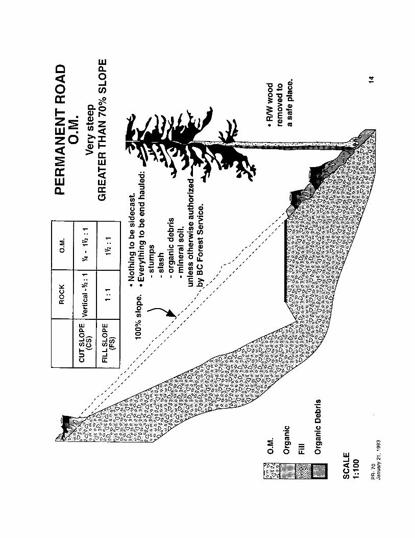
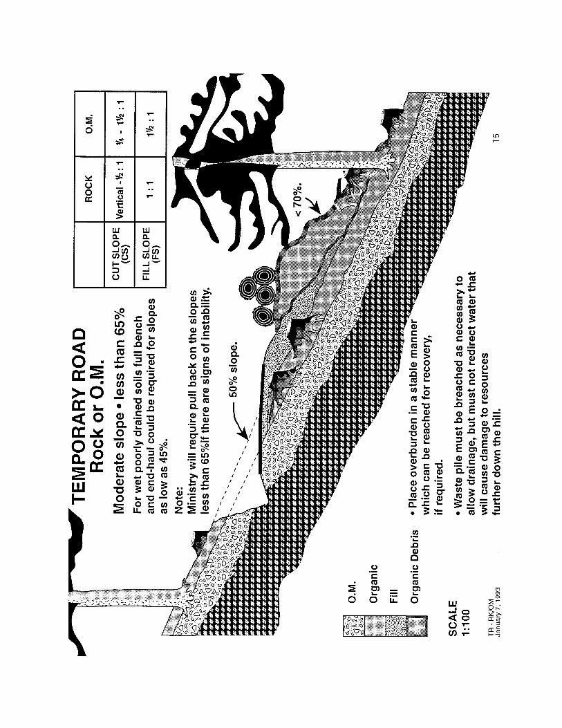
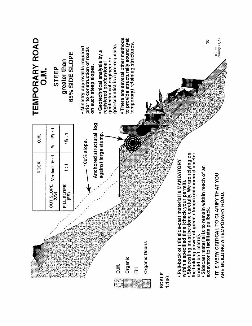
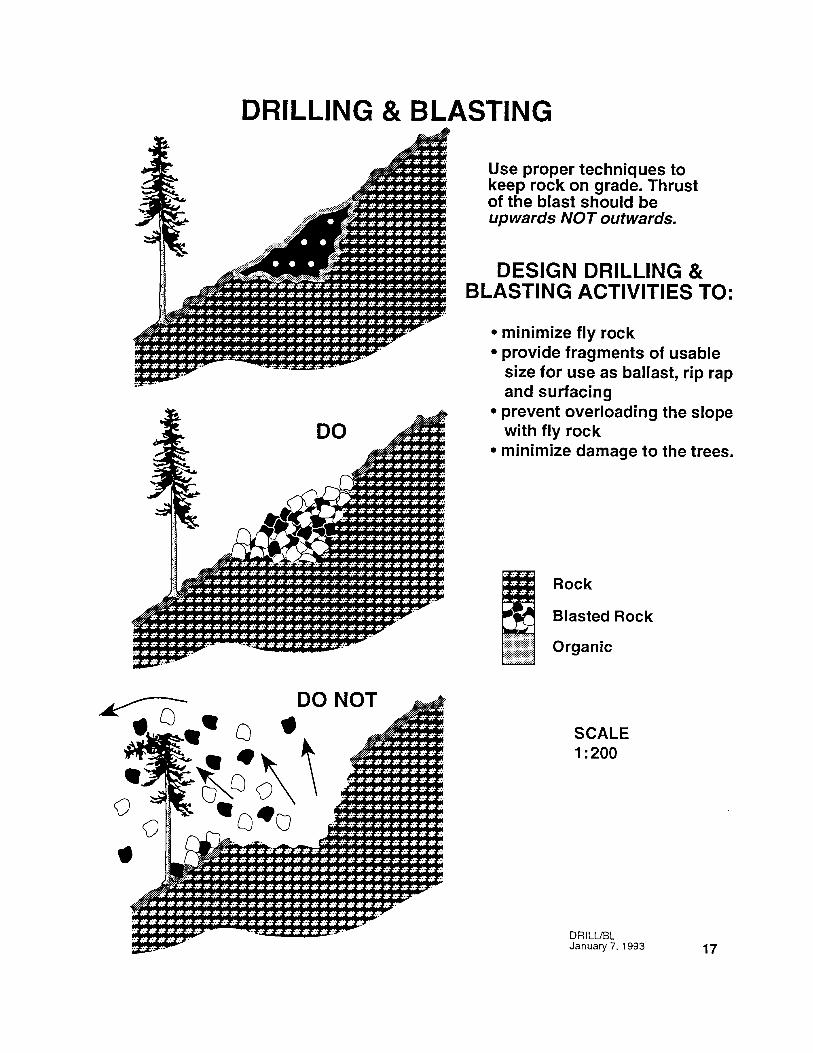

DRILLING&
BLASTING
Drilling and blasting techniques must accommodate:
• volume of material to be moved or created• sensitivity for rock type and structure• minimal flyrock• retention of blasted material on site• required rock fragmentation
The following general practices apply:
1. Drill holes to be in parallel, evenly spaced lines to achieve consistent burdenbetween individual holes, and between holes and outside edge of the rockformation.
____________
2. Stemming of all holes with 12 mm (1/2 in.) to 19 mm (3/4 in.) crushed rock ordrilling chips is required. Drill dust or dry dirt is not allowed. Stemming depthto be calculated with a minimum of 1.22 metres. Where required on horizontalholes utilize bags and a loading pole.
____________
3. All holes are to be drilled below subgrade using a rule of thumb 0.3 x burden.
November 30, 1992 18

4. The minimum stiffness ratio will be greater than 2 when using a 6.35 (2.5 in.)
cm hole and when the hole is greater than 3.05 metres (10 ft.) in length.
____________
5. In order to energize one row ahead before each row fires, timing delays will beutilized on each hole using the recommended m.s./ft delays for individual rocktypes.
____________
6. Stick powder is preferred where it is anticipated, or found, that normal blastingagents will not achieve the desired results. This does not preclude the use ofother agents and suitable multiple delay systems.
____________
7. Utilize the expertise of explosive suppliers and drilling and blastingprofessionals where required.
December 31, 1992 19
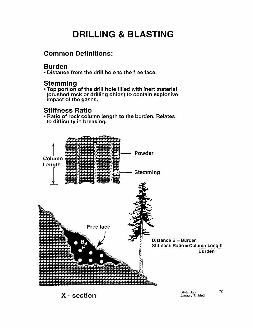
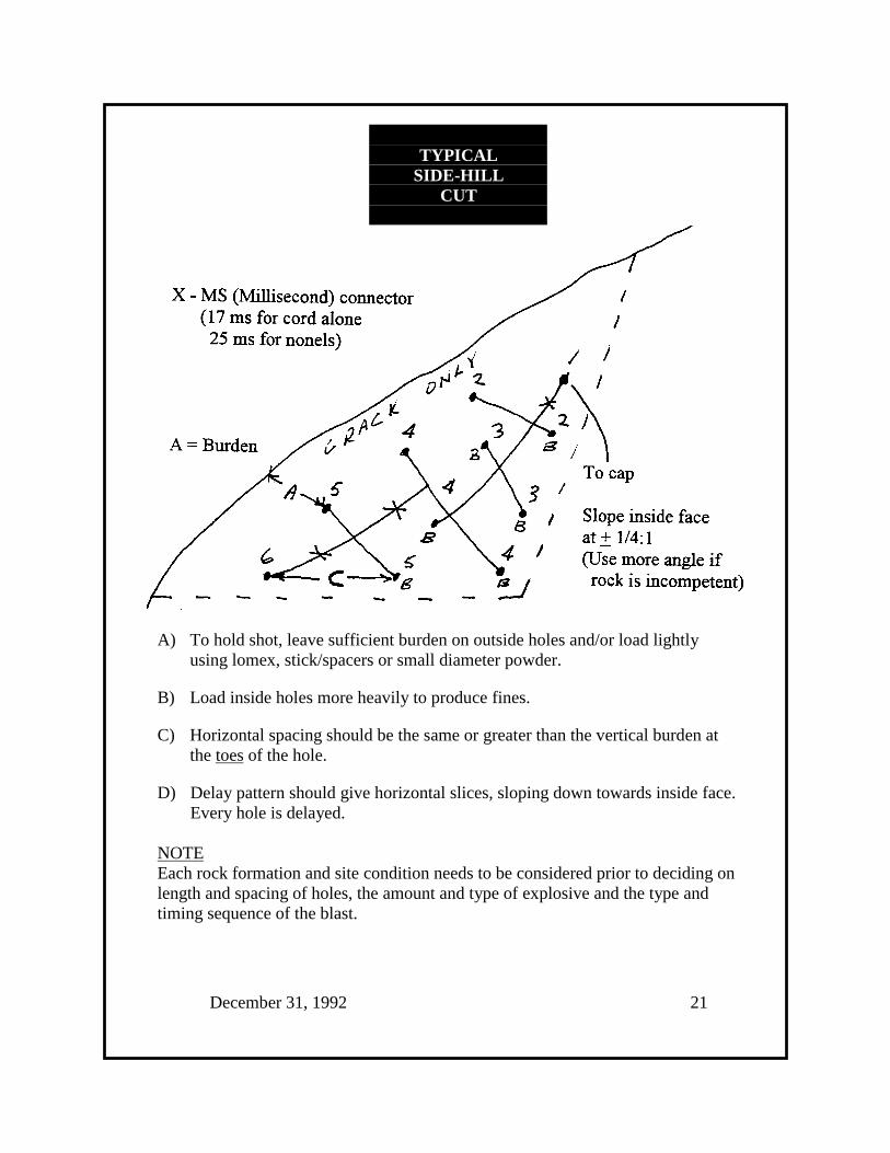
TYPICALSIDE-HILL
CUT
A) To hold shot, leave sufficient burden on outside holes and/or load lightlyusing lomex, stick/spacers or small diameter powder.
B) Load inside holes more heavily to produce fines.
C) Horizontal spacing should be the same or greater than the vertical burden atthe toes of the hole.
D) Delay pattern should give horizontal slices, sloping down towards inside face.Every hole is delayed.
NOTEEach rock formation and site condition needs to be considered prior to deciding onlength and spacing of holes, the amount and type of explosive and the type andtiming sequence of the blast.
December 31, 1992 21
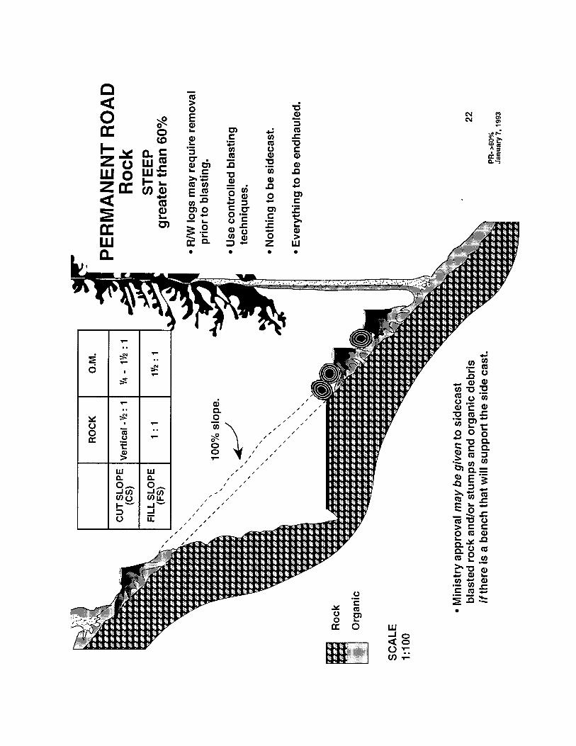
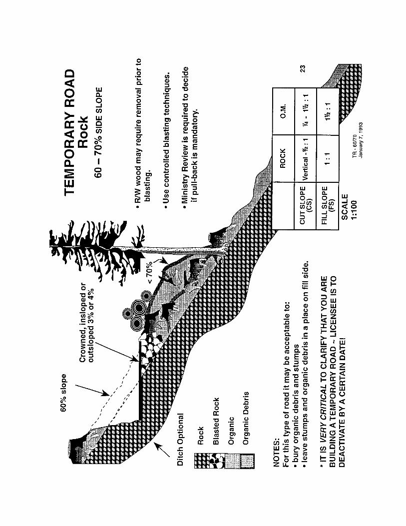
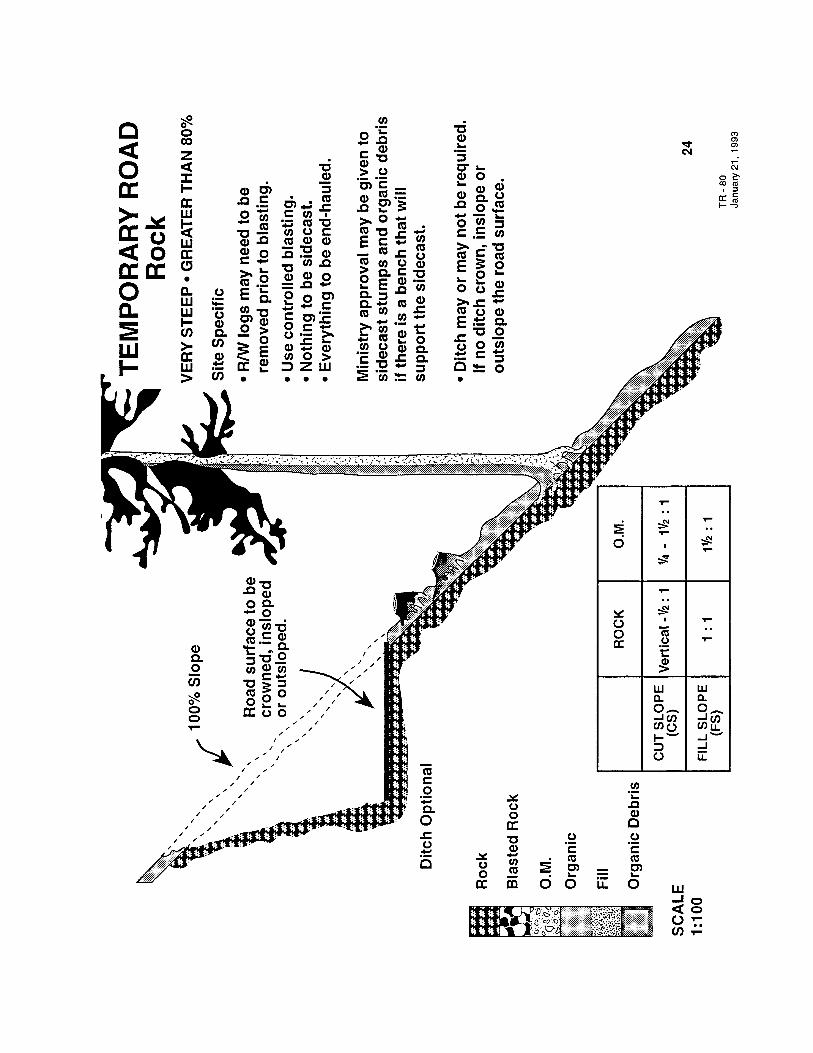
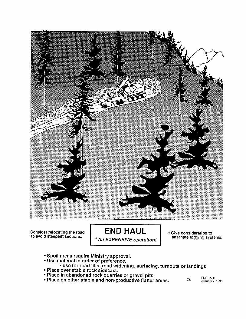
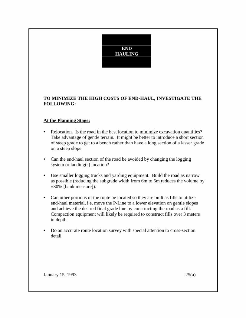
ENDHAULING
TO MINIMIZE THE HIGH COSTS OF END-HAUL, INVESTIGATE THEFOLLOWING:
At the Planning Stage:
• Relocation. Is the road in the best location to minimize excavation quantities?Take advantage of gentle terrain. It might be better to introduce a short sectionof steep grade to get to a bench rather than have a long section of a lesser gradeon a steep slope.
• Can the end-haul section of the road be avoided by changing the loggingsystem or landing(s) location?
• Use smaller logging trucks and yarding equipment. Build the road as narrowas possible (reducing the subgrade width from 6m to 5m reduces the volume by±30% [bank measure]).
• Can other portions of the route be located so they are built as fills to utilizeend-haul material, i.e. move the P-Line to a lower elevation on gentle slopesand achieve the desired final grade line by constructing the road as a fill.Compaction equipment will likely be required to construct fills over 3 metersin depth.
• Do an accurate route location survey with special attention to cross-sectiondetail.
January 15, 1993 25(a)

At the Design Stage:
• Design the road to minimize quantities by adjusting the horizontal and verticalalignments.
• Make the cut slope as steep as possible yet still stable.
• Calculate the amount of end-haul material required to be moved and calculatethe area planned for disposal to insure sufficient area is available. Rememberto use a suitable expansion and compaction factors.
• Place grade stakes on the cut side to insure only the amount of material neededto be excavated is excavated. Place fill stakes as required at the disposal site.
At the Construction Stage:
• Can a "tote road" be built through or around the end-haul section in order toutilize end-haul material for fill section(s) up-chainage of the end-haul section?This should also be a consideration at the location and design stage.
• Utilize the end-haul material for fills, ballasting, surfacing, turnouts andlandings.
At All Stages:
• Be innovative.
• Explore options.
• Have the road foreman and crew involved at any or all stages of the project toinsure the final plan is practical and can be done.
• Communicate the plan to all involved.
January 15, 1993 25(b)
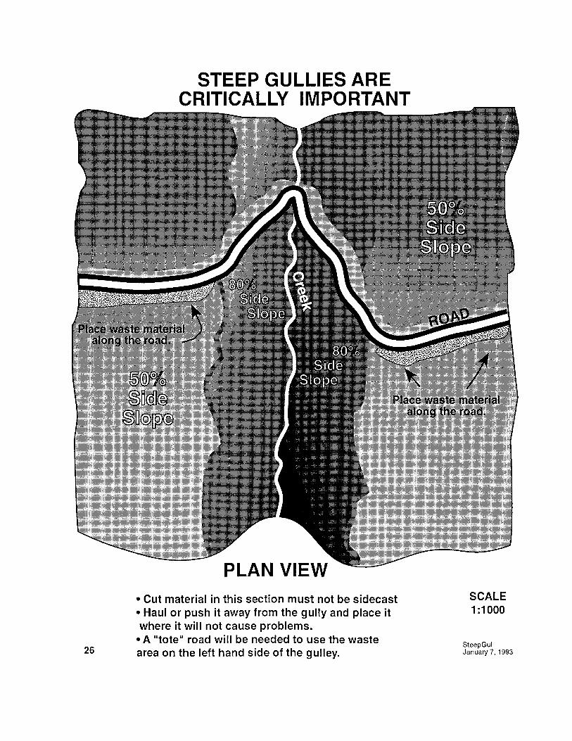

DRAINAGEPRINCIPLES
Maintain the natural drainage pattern.
____________
Every ephemeral, seasonal and perennial stream must have theirown drainage structure. Can be metal, wood, plastic, concrete
or in some cases a ford.
____________
In addition, install ditch culverts to handle road surface runoff,water seeping through the cut slopes and overland flow.
____________
DO NOT ALLOW
1. Silt laden ditch water to directly enter a Class I or II stream.
2. Water to run over unprotected, erodible sidecast∗ that is what causes erosion, siltation, road failures and in some cases,
landslides.
3. Water to pond in a ditch (except for catchment basins), on the road, or onsidecasted material.
February 11, 1993 27
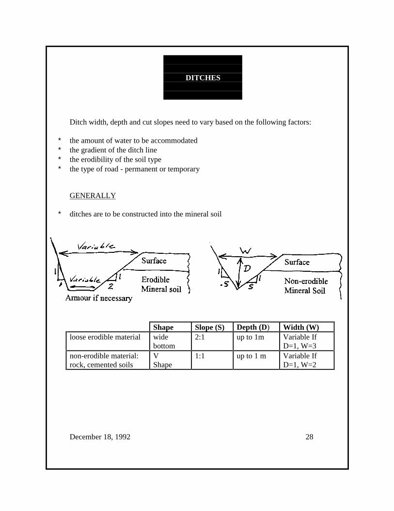
DITCHES
Ditch width, depth and cut slopes need to vary based on the following factors:
∗ the amount of water to be accommodated∗ the gradient of the ditch line∗ the erodibility of the soil type∗ the type of road - permanent or temporary
GENERALLY
∗ ditches are to be constructed into the mineral soil
Shape Slope (S) Depth (D) Width (W)loose erodible material wide
bottom2:1 up to 1m Variable If
D=1, W=3non-erodible material:rock, cemented soils
VShape
1:1 up to 1 m Variable IfD=1, W=2
December 18, 1992 28

Ditches may not always be required.
The construction of ditches requires additional excavation into the slope. Thisincreases the amount of material to be removed by the square of the horizontalwidth of the full bench, i.e.: full bench no ditch - 5 metres wide
full bench with 1 m ditch - 6
Increase in volume of excavated material is 62 - 52 = 36 - 25 = 11
11 x 100% = 44%25
____________
This increased volume results in:
∗ increase costs for excavation and sidecasting
∗ more exposed area for potential erosion and source of siltation
∗ increased volume to be sidecasted and possible slope overloading
∗ extra growing site disturbed
____________
Ditches may not be required for:
∗ top of vertical curves∗ temporary roads in rock∗ outslope or inslope roads∗ roads with swales built in
∗ full bench rock cuts(crown, inslope or outslope)
∗ overland construction
December 31, 1992 29

BUT
∗ if there is no ditch road and bank seepage water must be controlled bycrowning, insloping and/or by constructing a sufficient number of adequatedrainage grade breaks and swales at predetermined intervals.
____________
Open top culverts are also a good solution for roads without ditches and/or tointercept road surface water on long, steep gradients.
Grade Breaks and Rolling Dip (Swales) also are an excellent "self maintaining"drainage structure.
Ditch gradients steeper than 8% can give collected water too much momentum andthe ability to carry excessive sediment and debris for great distances.
This erosion leads to filling up the ditch where the gradient is shallow, cloggingculvert inlets and creating the possibility of carrying sediment into streams.
December 31. 1992 30
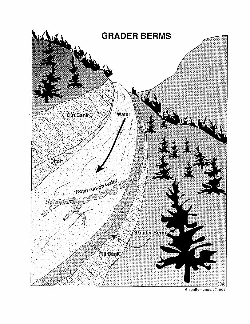
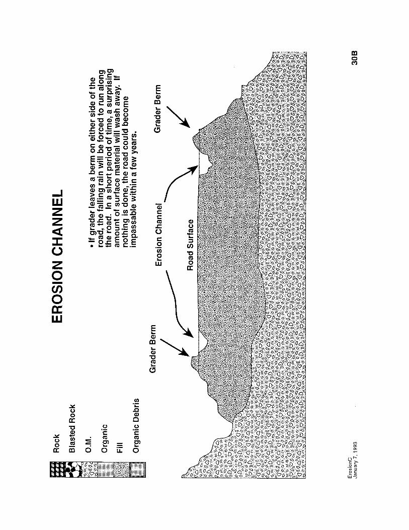
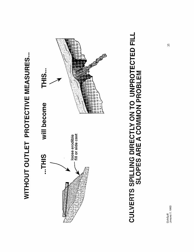
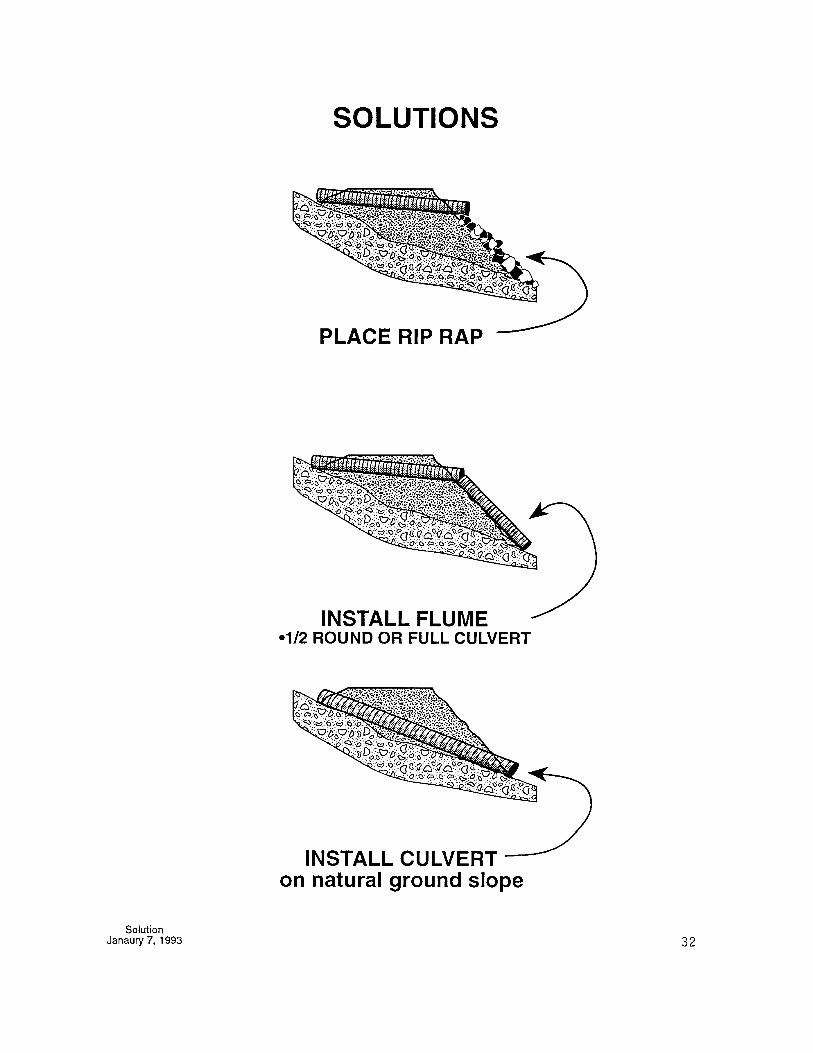
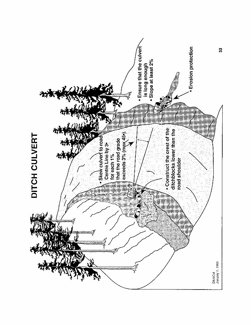
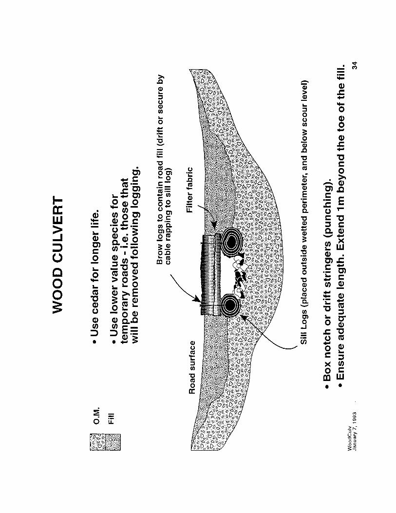
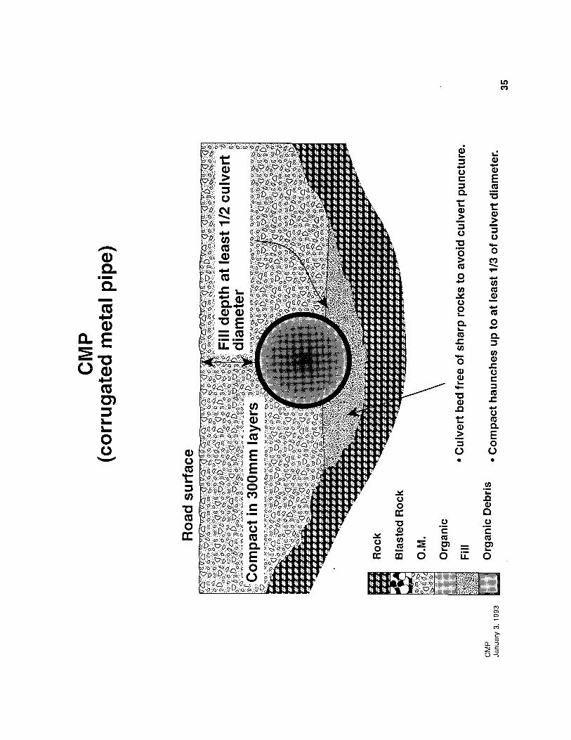
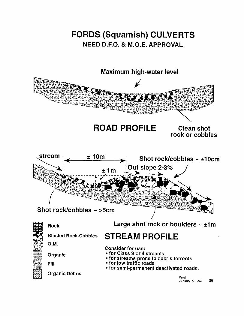
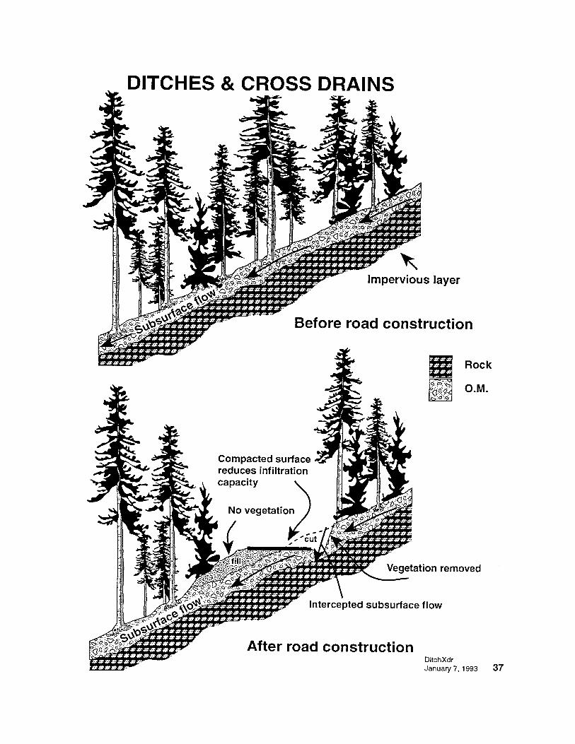
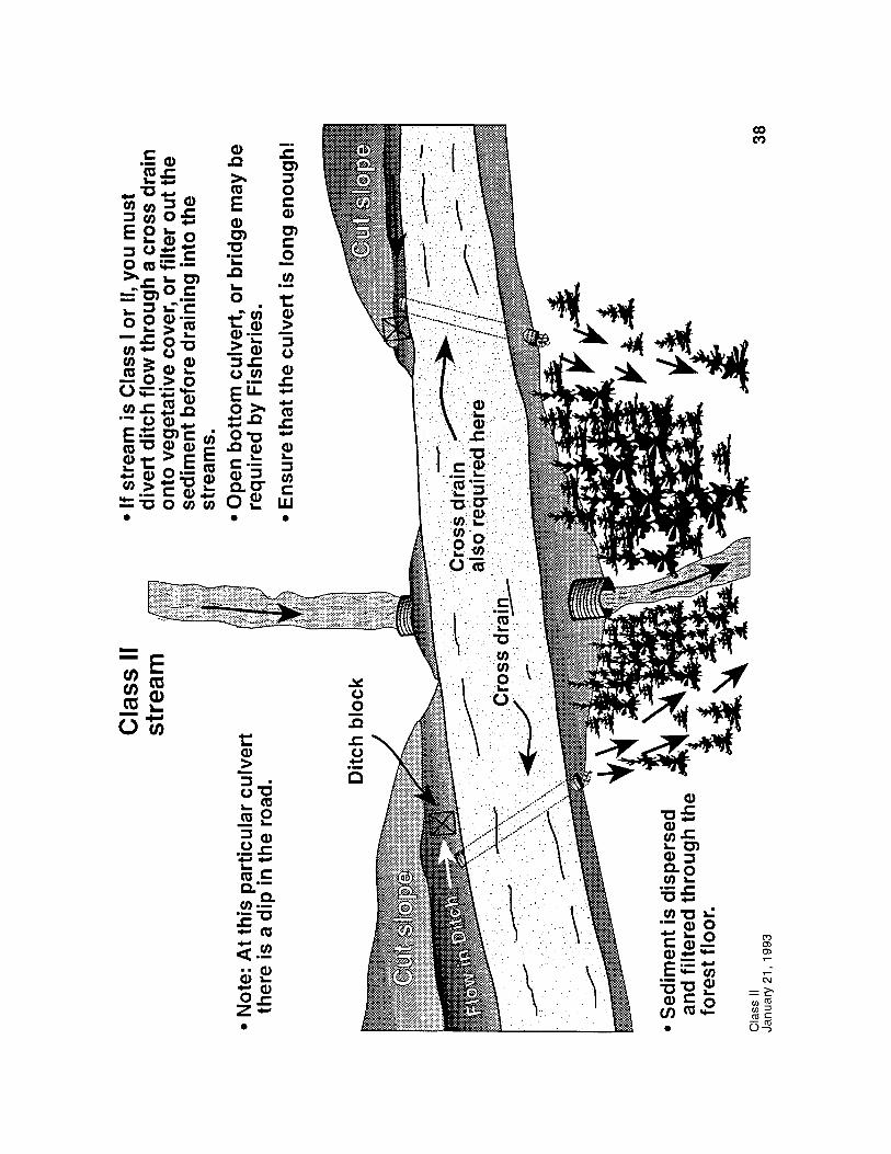
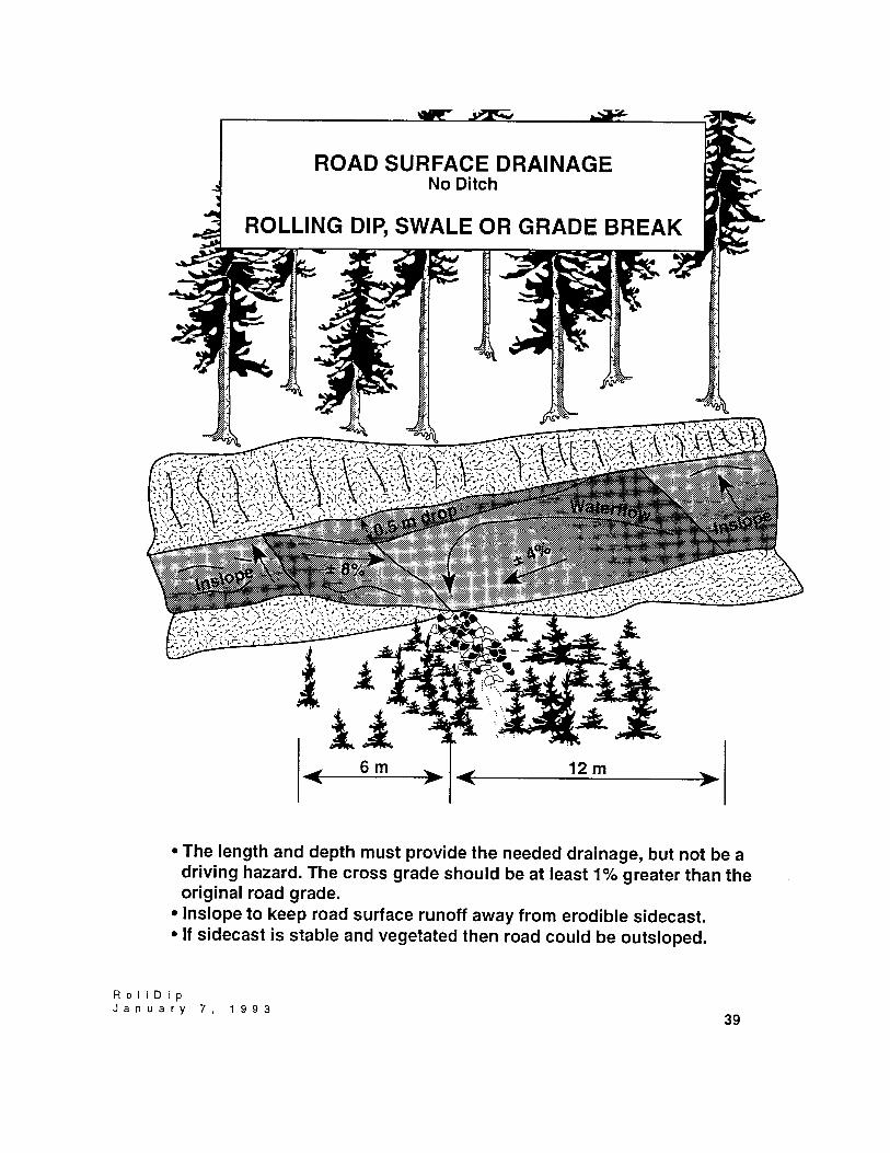
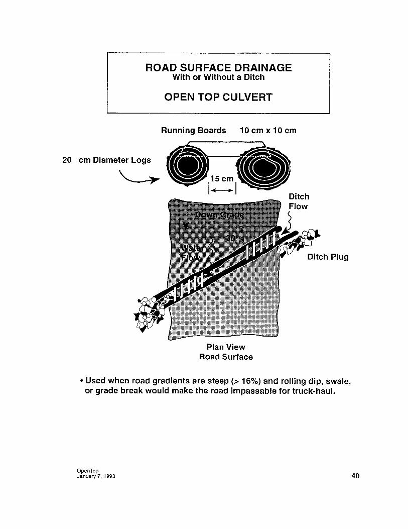

REVEGETATION
ObjectiveTo minimize surface erosion revegetate all exposed and plantable surfaces with:
∗ Grasses and legumes - by hand- by hydraulic seeder
∗ Shrubs
∗ Specie selection for both can be site specific. Check the local MinistryR.O. Engineering for advice.
____________
• When building road by sidecasting save the top soil and place it on top ofmineral soil to provide a better growing medium. Overburden from landingsand pits can also be stockpiled for future use.
• Keep the sidecast slope <70% and make it rough to provide plantable sites.
Areas of priority∗ around streams∗ erodible sidecasts and fills∗ bridge fills∗ ditches∗ plantable cut slopes∗ spoil areas∗ gravel pits
• The time to seed is after construction in the spring after thaw and/or the fallbefore the freeze.
December 31, 1992 41

MAINTENANCE
Often it is not the road construction that causes the damage but the lack ofmaintenance. Somebody has to be appointed to be responsible for maintenance.
1. Clean out culverts before they wash out. A 5 minute stop by an alert operatoror resource assistant could prevent major damage!
2. If ditch erosion is becoming noticeable do something about it. Considerinstalling another cross-drain culvert.
3. Clean out ditches and culverts during and/or immediately after yardingoperations and when necessary.
4. Ensure road surface drains properly. Maintain adequate crown orinslope/outslope the road surface.
5. Look for and repair sloughing cut banks.6. Drain ponding water7. Look for tension cracks. If a failure appears likely, pull back the sidecast. If it
is settlement, fill in the tension cracks by excavating and repacking the roadbed to prevent water from entering and further saturating the fill andlubricating a potential failure plane. Keep water away from such areas.
8. Minimize disturbance to revegetated areas. Revegetate disturbed areas causedby maintenance activities.
9. Inspect roads:
∗ during and after logging; clean out ditches and culverts;∗ prior to Fall rains;∗ during and/or after major storms;
∗ while you are driving the road; fix what you can while you are there andreport potential problems to those who are responsible for that road.
10. Remove or frequently breach grader berms to provide drainage relief. Carerequired to choose outlet location.
February 11, 1993 42

DEACTIVATION
KEY POINTS
• Locate and construct the road to minimize the need for deactivation works.____________
• There must be a deactivation plan - know what it is and carry it out.____________
• It must identify the short/long term needs for the road.____________
• Deactivate as you go - expensive to bring equipment back.____________
• Deactivation measures can include:
∗ bridge and culvert removal∗ construction of fords∗ road crowning, insloping or outsloping∗ construction of cross-ditches and/or water bars∗ cut slope stabilization∗ ditching∗ sidecast pull back∗ slide rehab projects∗ armouring∗ vegetation
February 11, 1993 43

DEACTIVATION
• Depending on what the short and long term plan for the road or area is,deactivation of a road can include some or all of the above measures.
• Deactivation work is best done during dry weather.
• The main concept for all levels of deactivation is to insure the "naturaldrainage pattern" is established in a maintenance free fashion and that water isdispersed in small amounts in intervals that do not cause damage.
• Always be careful where water is to be directed. Many slides or other types ofdamage has occurred because of the lack of attention to this importantconsideration.
• Don’t trust ditches
THE MINISTRY HAS 3 LEVELS OF DEACTIVATION:
1. Temporary (Seasonal)2. Semi-Permanent (Rotation Maintenance)3. Permanent
February 11, 1993 44(a)
1. Temporary (Seasonal) Deactivation:
• Use temporary deactivation when regular use of the road is to be suspendedfor up to three years.
• Do when a road is to be left unmaintained.
• Do for roads or road sections having ditches prone to plugging or washingout.
• Decide what kind of access is required (2wd, 4wd, ATV, Mountain Bike,Trail, etc.).
(a) Remove or breach any windrows on the outer edge of the road surface.(b) Carry out inspections after major storms, during spring breakup and prior
to fall rains, to assess the adequacy of ditches and culverts, andrequirements for improved drainage works or road surfacing orrevegetation.
(c) Carry out required maintenance.(d) Repair bridges as necessary to protect the user during the period of
deactivation.(e) In areas of sensitive and steep terrain, or heavy rainfall, construct
waterbars or cross-ditches along the road to prevent accumulation andchannelizing of excessive flow down the road surface or ditch line.
(f) Do whatever is required to protect the road and the other resource valuesthat may be affected.
(g) Remove drainage structures as required.(h) Drain the road surface as necessary by crowning, insloping or outsloping.
February 11, 1993 44(b)
2. Semi-Permanent Deactivation (Rotation Maintenance):
Use semi-permanent deactivation for winter roads, for roads in particularlyisolated areas where regular use is suspended for up to three years, and whenharvesting is suspended until further logging or the next rotation.
• Decide what type of access is required (2wd, 4wd, ATV, Mountain Bike,Trail, etc.).
(a) Except for flat areas with minimal downslope consequences, restore thenatural flow patterns by removing all existing stream culverts, restoringchannel stability, and installing fords where possible if access is requiredduring the period of deactivation. Alternatively, back up stream culvertswith similarly sized cross-ditches on the downhill side.
(b) Back up stream culvert excavations with a cross-ditch on the downhillside, where overflow of the stream channel is anticipated.
(c) Except for flat areas with minimal downslope consequences, remove allcross-drain culverts and replace with cross-ditches. Ensure that ditchblocks are intact.
(d) Construct additional cross-ditches on steep grades, at locations of heavyground water seepage, at switchbacks and at road junctions.
(e) Construct cross-ditches using the criteria given in the sketch on Page 47.(f) Remove temporary and semi-permanent bridges or, if the bridges are to
be left in service, repair and replace them as necessary to protect usersduring the period of deactivation.
(g) Remove or breach any windrows on the road surface.(h) Outslope/inslope the road surface, as appropriate.(i) Pull-back sidecast fill onto the outsloped road grade, to ensure drainage,
where there is a high risk of slope failure where stability of the fill isquestionable. Place this fill material against the cut slope at the angle ofrepose or flatter. Ensure that cross-ditches are installed where theditchline ends. Revegetate exposed soils surfaces.
(j) If erosion or sedimentation is a concern, armour the exposed erodiblebottom surfaces of waterbars, x-ditches and fords and their outlets.
February 11, 1993 44(c)

3. Permanent Deactivation:
Use permanent deactivation when the road is to be closed permanently.
(a) Restore the natural flow patterns by removing all existing stream culvertsand restoring channel stability.
(b) Back up stream culvert excavations with a cross-ditch on the downhillside, where overflow of the stream channel is anticipated.
(c) Remove all cross-drain culverts and replace with open cross-ditches, andensure that ditch blocks are intact.
(d) Construct additional cross-ditches at locations of steep grades, heavyground water seepage, at switchbacks and at road junctions, and whereditches are prone to plugging.
(e) Construct cross-ditches using criteria given in the sketch on Page 47.(f) Remove all bridge superstructures. Remove substructures where failure
will affect downstream values.(g) Remove any windrows on the road surface.(h) Outslope/inslope the road surface, as appropriate.(i) Pull-back sidecast fill onto the outsloped road grade, to ensure drainage,
where there is a high risk of slope failure during major rainstorms, orwhere stability of the fill is questionable. Place this fill material againstthe cut slope at the angle of repose or flatter. Ensures that cross-ditchesare installed where the ditchline ends. Revegetate exposed soil surfaces.
(j) Scarify the road surface, if required, and revegetate.
January 13, 1993 45

CROSS DITCHES& WATER BARS
Cross-ditch
Purpose:To capture and divert both road surface water and ditch water off and/or across theroad.
____________
Notes:• Excavate the cross-ditch to a depth that will allow a direct hydraulic
connection to road-side ditch.• Provide a ditch block on the downhill side of the cross-ditch.• Construct cross-ditch with minimum skew angle of 30 degrees to the
perpendicular of the road centre-line.• Construct a berm on downgrade side of cross-ditch.• Flatten berm and widen ditch to accommodate vehicle traffic, as necessary.• Do not direct water to an erodible area.• Protect cross ditch channel and outlet as necessary to prevent excessive
erosion.
January 5, 1993 46
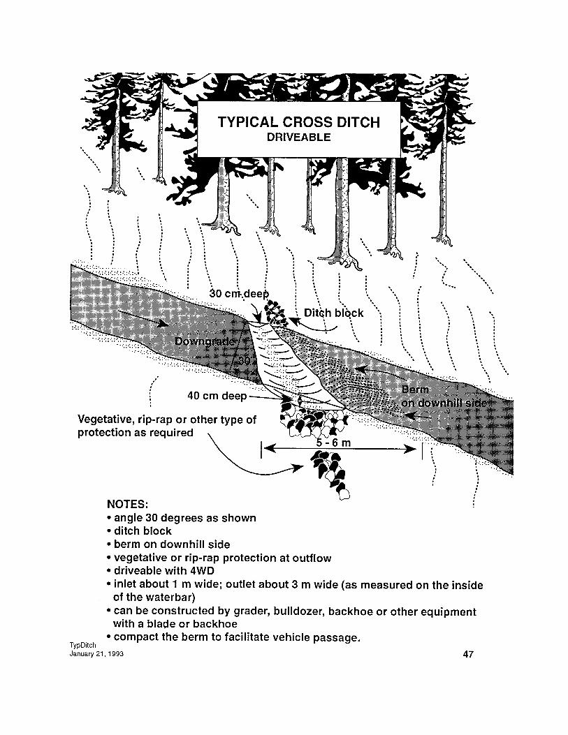

Waterbar
Purpose:To capture and divert road surface water off the road to the fill side or across theroad to the ditch side (reverse waterbar).
Note that the waterbar is unlike the cross-ditch where the ditch water is also aconcern.
____________
Notes:• Depth of waterbar ditch below the road surface is typically shallow.• Skew as required.• Install a berm on downgrade side of waterbar ditch.• Flatten berm and widen ditch to accommodate vehicle traffic as necessary.
• Provide erosion protection as necessary at the outflow.
January 4, 1993 48
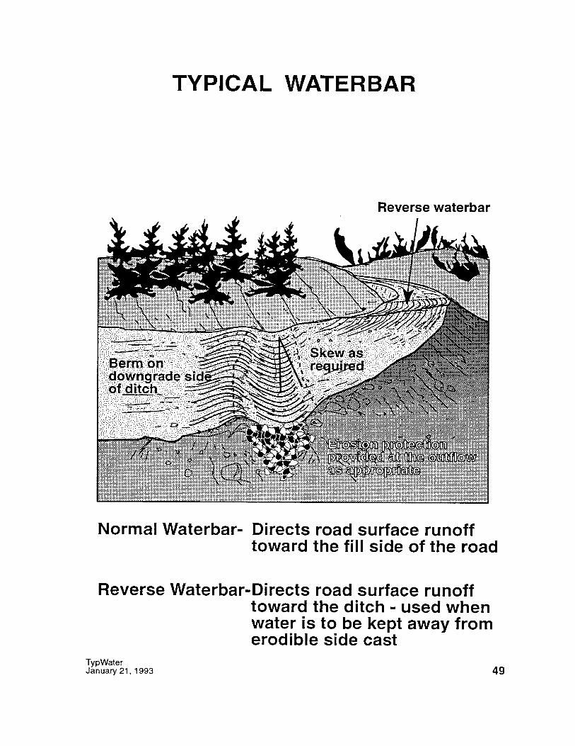
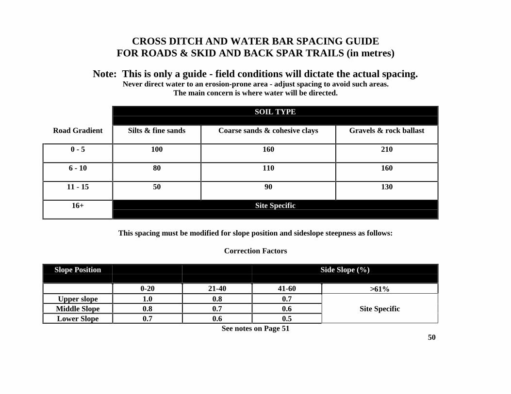
CROSS DITCH AND WATER BAR SPACING GUIDEFOR ROADS & SKID AND BACK SPAR TRAILS (in metres)
Note: This is only a guide - field conditions will dictate the actual spacing.Never direct water to an erosion-prone area - adjust spacing to avoid such areas.
The main concern is where water will be directed.
SOIL TYPE
Road Gradient Silts & fine sands Coarse sands & cohesive clays Gravels & rock ballast
0 - 5 100 160 210
6 - 10 80 110 160
11 - 15 50 90 130
16+ Site Specific
This spacing must be modified for slope position and sideslope steepness as follows:
Correction Factors
Slope Position Side Slope (%)
0-20 21-40 41-60 >61%Upper slope 1.0 0.8 0.7
Middle Slope 0.8 0.7 0.6 Site SpecificLower Slope 0.7 0.6 0.5
See notes on Page 5150
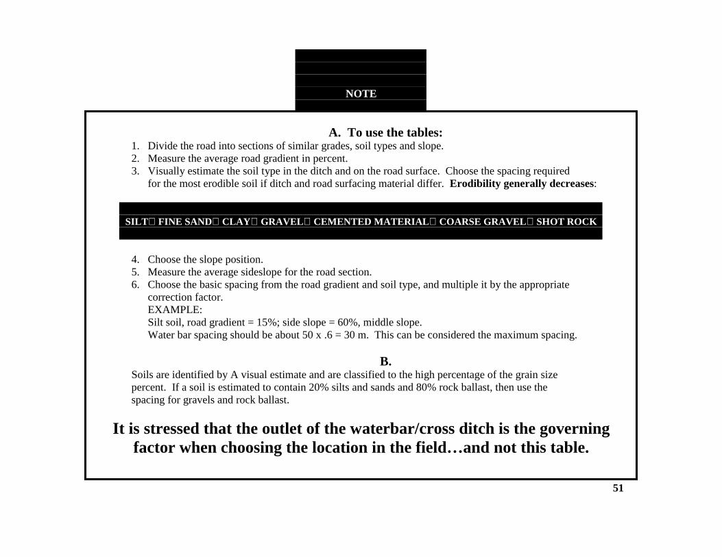
NOTE
A. To use the tables:1. Divide the road into sections of similar grades, soil types and slope.2. Measure the average road gradient in percent.3. Visually estimate the soil type in the ditch and on the road surface. Choose the spacing required
for the most erodible soil if ditch and road surfacing material differ. Erodibility generally decreases:
SILTFINE SANDCLAYGRAVELCEMENTED MATERIALCOARSE GRAVELSHOT ROCK
4. Choose the slope position.5. Measure the average sideslope for the road section.6. Choose the basic spacing from the road gradient and soil type, and multiple it by the appropriate
correction factor.EXAMPLE:Silt soil, road gradient = 15%; side slope = 60%, middle slope.Water bar spacing should be about 50 x .6 = 30 m. This can be considered the maximum spacing.
B.Soils are identified by A visual estimate and are classified to the high percentage of the grain sizepercent. If a soil is estimated to contain 20% silts and sands and 80% rock ballast, then use thespacing for gravels and rock ballast.
It is stressed that the outlet of the waterbar/cross ditch is the governingfactor when choosing the location in the field…and not this table.
51
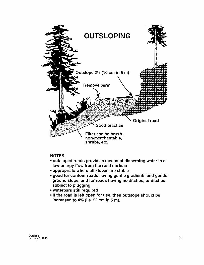
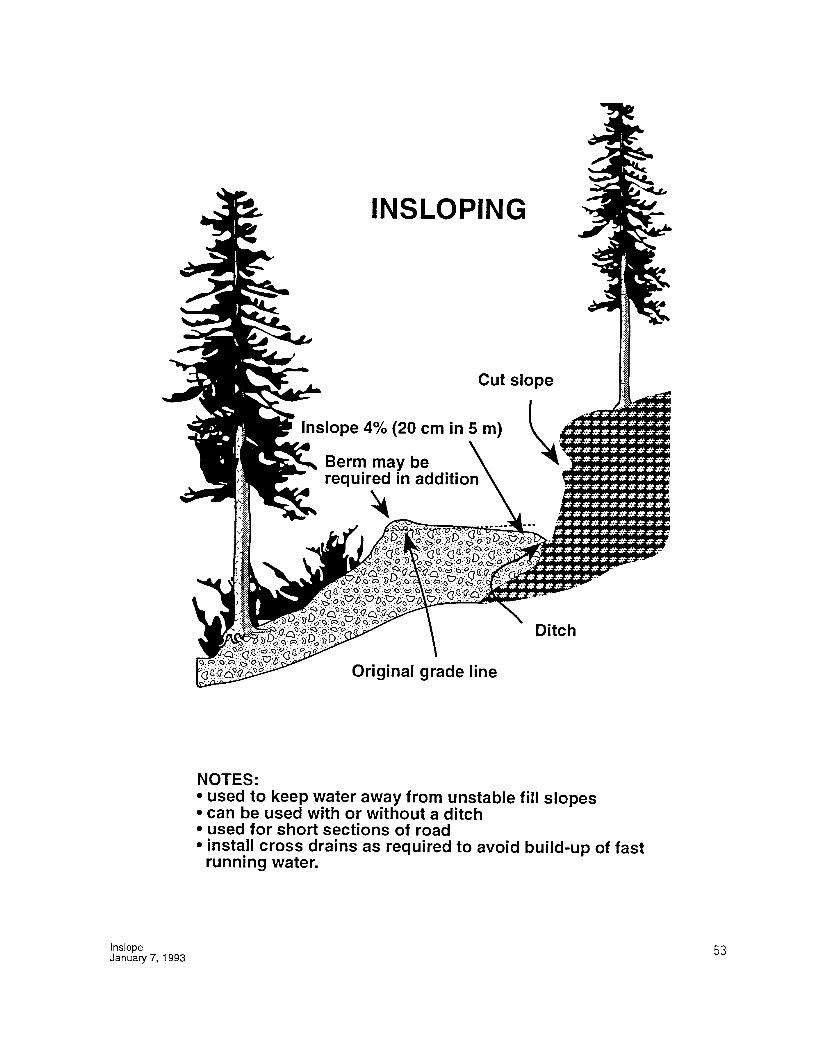
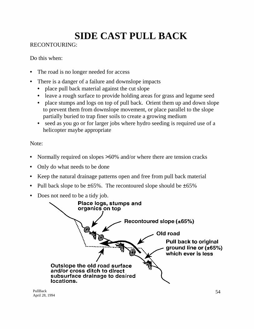
SIDE CAST PULL BACKRECONTOURING:
Do this when:
• The road is no longer needed for access
• There is a danger of a failure and downslope impacts• place pull back material against the cut slope• leave a rough surface to provide holding areas for grass and legume seed• place stumps and logs on top of pull back. Orient them up and down slope
to prevent them from downslope movement, or place parallel to the slopepartially buried to trap finer soils to create a growing medium
• seed as you go or for larger jobs where hydro seeding is required use of ahelicopter maybe appropriate
Note:
• Normally required on slopes >60% and/or where there are tension cracks
• Only do what needs to be done
• Keep the natural drainage patterns open and free from pull back material
• Pull back slope to be ±65%. The recontoured slope should be ±65%
• Does not need to be a tidy job.
PullBackApril 28, 1994
54
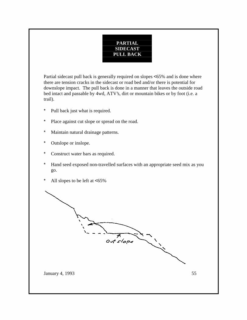
PARTIALSIDECAST
PULL BACK
Partial sidecast pull back is generally required on slopes <65% and is done wherethere are tension cracks in the sidecast or road bed and/or there is potential fordownslope impact. The pull back is done in a manner that leaves the outside roadbed intact and passable by 4wd, ATV’s, dirt or mountain bikes or by foot (i.e. atrail).
∗ Pull back just what is required.
∗ Place against cut slope or spread on the road.
∗ Maintain natural drainage patterns.
∗ Outslope or inslope.
∗ Construct water bars as required.
∗ Hand seed exposed non-travelled surfaces with an appropriate seed mix as yougo.
∗ All slopes to be left at <65%
January 4, 1993 55
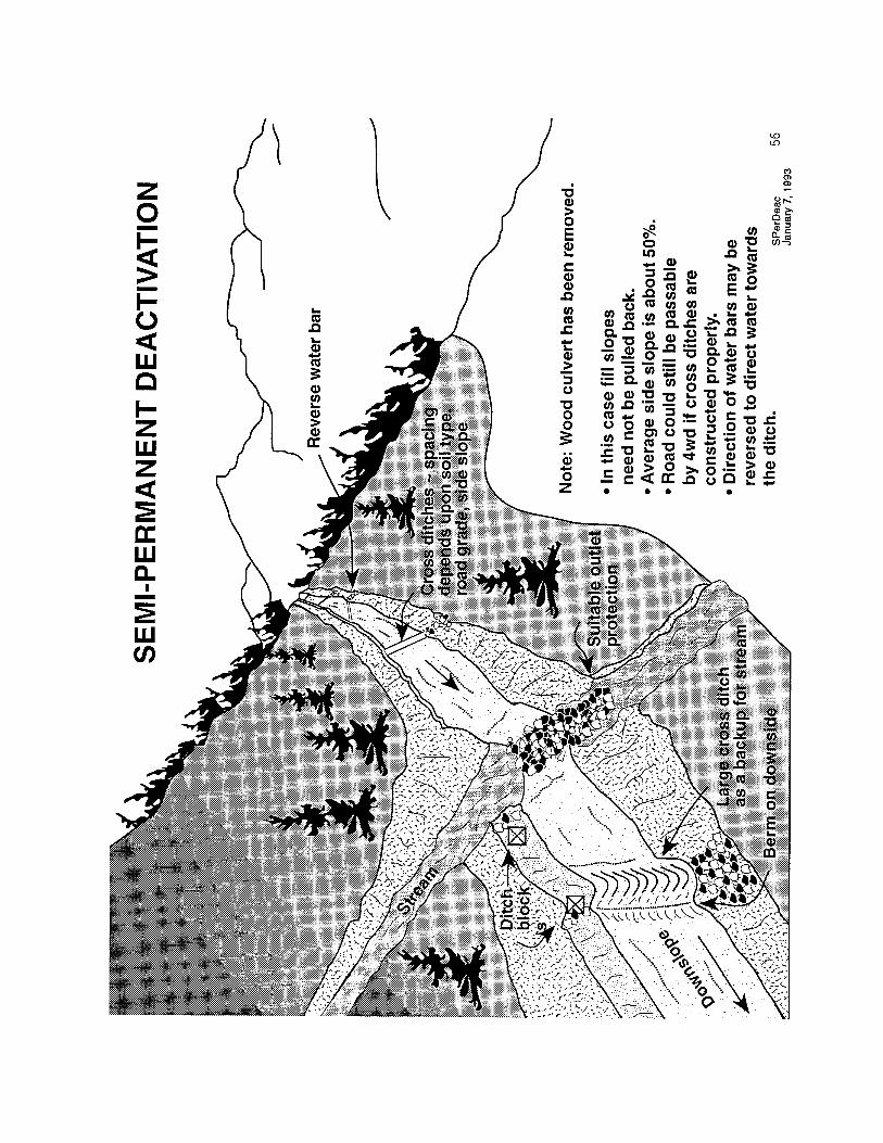
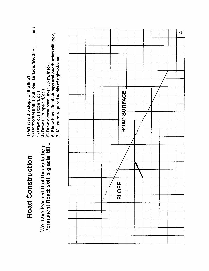
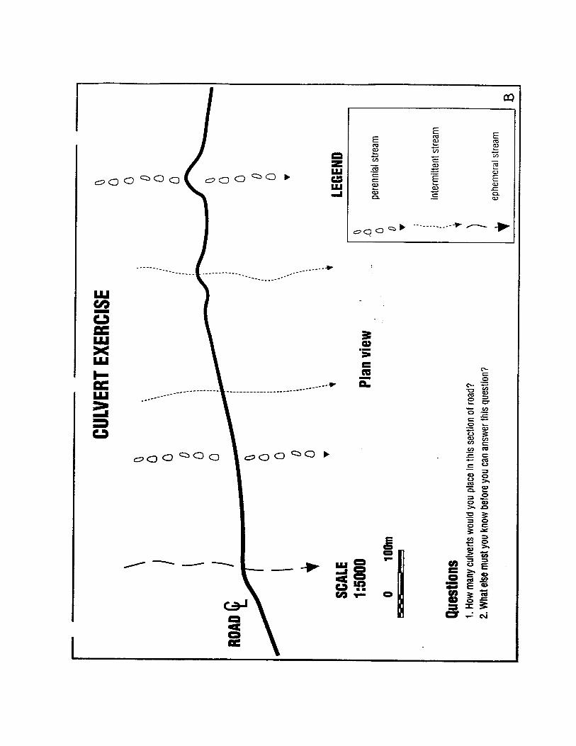

CULVERTEXCERCISE
Refer to page ’D’
1. Clearly indicate location of ditch blocks.
2. What things would you consider before decidingwhether or not to use a "trash rack" at this site?
3. Where might you place the "trash rack"?
C
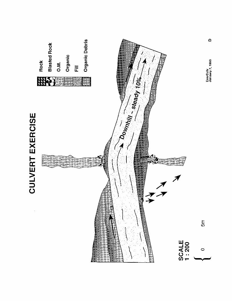

DEACTIVATIONEXCERCISE
Refer to page ’D’
If you were permanently deactivating thisroad and you were worried about the largeamount of debris upstream, what wouldyou do for this section of road?
E

DEACTIVATIONEXCERCISE
Refer to page ’G’
1. Clearly note on the attached sketch what shouldbe done to permanently deactivate this road.
• Road grade is 15% (up hill to the right).• Soil is sandy.
Use these symbols:
F
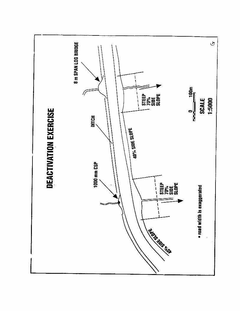
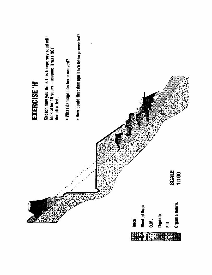
*HRPRUSKLF�6WXGLHV�•�(URVLRQ��6HGLPHQWDWLRQ�3URFHVVHV�•�:LOGODQG�+\GURORJ\�•�(URVLRQ�&RQWURO3�2��%R[������•�$UFDWD��&DOLIRUQLD�•�������•�������������
Techniques and Costs ForEffective Road Closure
William WeaverDanny Hagans
IntroductionMost private and public forest lands in the western U.S. are plagued by extensive networks ofabandoned, currently unused or unwanted access and service roads built by landowners andresource managers. For example, after timber harvest and restocking, there may be little need orincentive for forest landowners to properly maintain spur roads which no longer accessmarketable timber resources. The tendency is to abandon these currently unneeded roads untilaccess to the area is again desired.
In steepland areas of northwestern California, many harvested watersheds contain extensiveroad networks that have been progressively constructed over several decades. For example, in a30,000 acre area of the Redwood Creek basin that is currently managed for timber resources,over 175 miles of logging road have been constructed since 1947. As of 1985, from 65 percentto over 90 percent of the road systems in four inventoried sub-basins were no longer beingmaintained. An average of 53 percent of the road network was no longer passable to vehicles.Many sections of these abandoned and unmaintained roads exhibit serious and persistent erosionproblems. Other roads remain largely intact but display the potential for substantial erosionduring future winter storms.
The degree of erosion and off-site sedimentation effects caused by abandoned roads isdependent upon a number of factors including: 1) the date of road abandonment, in relation tothe occurrence of past and future winter storms and flood events, 2) terrain characteristics(slope steepness, the number and size of stream channels crossed, natural slope and soil stability,and soil erodibility), and 3) road characteristics (adequate culvert size, proper culvert locationand installation, adequate debris "filters" to prevent culvert plugging, and the grade of theroadbed over the stream crossing).
Erosion and sedimentation effects caused by forest roads can be both local and far removedfrom the site. For example, an undersized culvert which becomes plugged or whose capacity isexceeded by storm runoff can cause erosion at the site where it is installed as all or part of thefill crossing is washed out. In addition, streamflow can be diverted from the channel and causeconsiderable erosion in downslope areas where gullies will form, and in far removed fish-bearing streams where the sediment is finally deposited.
In addition to being spatially displaced from its source, the adverse effect may also be delayed intime. The undersized culvert on an abandoned road may not plug or its capacity be exceeded formany years, and the resultant erosion and sedimentation may not occur for decades after theoriginal disturbance. An entire road network, which is not being permanently maintained orwhose culverts have been under-designed (because they were installed many years ago), may
3DFLILF�:DWHUVKHG�$VVRFLDWHV���3�2��%R[��������$UFDWD���&$�������������������������
(URVLRQ�3URRILQJ���SDJH��
not reveal significant erosional impacts from road construction until a major storm causeswidespread culvert failure, stream crossing erosion and stream diversions. Similarly, mass soilmovement of unstable sidecast materials may not occur for years following placement, asorganic debris decomposes and subsurface hydrology interacts with newly loaded slopes.
Fluvial (Gully) Erosion from Abandoned RoadsStream diversions at logging road and side trail stream crossings have been found to be theoverwhelming, leading cause of sediment production from abandoned, unmaintained roads inthe 280 mi2 Redwood Creek basin. Diverted waters often created large, complex gully systemswhich are responsible for documented increases in hillslope drainage density, sedimentproduction and yield, and enlarged stream channels. These hillslope processes, in turn, led tofurther off-site impacts associated with stream channel aggradation. Although most road-relatederosion occurs during relatively short-lived, large magnitude storms, the heavy runoff merelyacts to trigger accelerated erosion that had been pre-destined by certain landuse practices.
Triggering mechanisms for stream diversions are almost always traceable to either culvertplugging, undersized culverts whose capacity is exceeded during storms, or the absence of aculvert at the crossing of an intermittent or ephemeral stream. By whatever method the culvertis overtopped, diversion of streamflow can only occur if the stream crossing itself wasconstructed with a high diversion potential (DP); that is, at locations where the road and ditchsystem slope away from the crossing in at least one direction. This allows streamflow to bediverted down the road.
To describe this situation, a diversion potential rating system was developed. It is based solelyand simply on the gradient of the road as it crosses a stream channel. Each crossing is examinedin the field and assigned one of two potentials. For crossings with no diversion potential, theroad gradient on both approaches dips into the stream channel at the crossing. Even if theculvert plugs, flow cannot escape the drainage system. For crossings with a high diversionpotential, the road surface slopes away (down) from the stream crossing in at least one direction.The steepness of the road as it slopes away from the crossing affected the size of the gully thatdeveloped on the road or in the ditch, but any slope more than about 0.5 percent was found to besufficient to divert the streamflow.
Uncontrolled streamflow at crossings constructed with no diversion potential can, at worst, onlyerode the volume of material placed in the fill crossing; no extensive gully networks can developfrom diverted water. However, stream crossings constructed with a high diversion potentialhave been inadvertently designed to create extensive gully systems on adjacent hillslopes whenstream flow exceeds the capacity of the culvert, for whatever reason, and is diverted out of itsnatural channel.
There are thousands of stream crossings in the Redwood Creek watershed, and on other landsthroughout northern California, which exhibit high diversion potentials but whose culverts havenot yet plugged. These crossings are "loaded guns" waiting for a large storm and flood to cause
3DFLILF�:DWHUVKHG�$VVRFLDWHV���3�2��%R[��������$UFDWD���&$�������������������������
(URVLRQ�3URRILQJ���SDJH��
culvert plugging and stream diversion. Many other culverted crossings have already pluggedand experienced stream diversions at least once since they were installed.
For example, 70 percent of the logging road stream crossings surveyed in the lower RedwoodCreek basin were constructed with a high diversion potential. Of these, 56 percent haveexperienced diversions at least once, only to be reconstructed again with a high diversionpotential. Based on the sample percentages, we estimate there are over 5,200 stream crossingsin the 280 mi2 Redwood Creek basin alone which have been constructed with a high streamdiversion potential. When major storms occur in the future, or if the stream bed very mobile atthese sites, the mechanism still exists to once again plug the culvert, divert the flow andsignificantly accelerate fluvial sediment yield to stream channels through hillslope gullying.
Mass Movement of Sidecast MaterialsThe winter of 1981-2 produced several moderate precipitation events (maximum ten-year returninterval for 24 hour rainfall) which resulted in numerous hillslope failures in the lower RedwoodCreek basin. Each was in some way associated with logging roads or tractor skid trailsconstructed for previous timber harvesting. Particularly evident were debris flows and debristorrents. Coincidentally, these are the hillslope landslides that are most amenable to cost-effective treatment and prevention.
A detailed study of these failures yielded a data base which has been used to refine watershedrehabilitation and erosion control practices in the basin and could be of considerable utility inimproving and directing road construction, road closure and road abandonment practices onsteep forest land elsewhere (LaHusen, 1984). Identification of their pre-failure morphology andlikely location are essential for effectively closing and erosion-proofing roads which cross steep,steam-side slopes.
All 40 hillslope failures observable from low altitude aerial reconnaissance of a 77 mi2 studyarea were examined. In addition to a dimensional survey, a field inspection of each failure wasperformed to document slope shape, slope gradient, hillslope aspect, and distances to streamsand the nearest major change in slope gradient. Site examination also included soil profiledescriptions, vegetative associations and spatial relationships to roads, skid trails, and tractor orcable yarded harvest units. The year of road construction and harvest histories were determinedfrom aerial photographs. Impacts inventoried included: 1) size and quantity of sediment andorganic debris delivered to streams, 2) formation of log-jams and 3) damage to old growthforest lands. Local continuous rainfall records wee analyzed to define precipitation intensitiesand to identify possible hydrologic controls on slope stability.
Although the failure volumes (157 yd3 - 12,550 yd3) and sediment delivery volumes 0 yd3 -8.250 yd3) varied widely, specific site conditions were remarkably similar. All debris flowsoriginated in and consisted predominately of landing, road or skid trail side-cast fill material.Once initiated, these mass movements often induced failure in original ground.
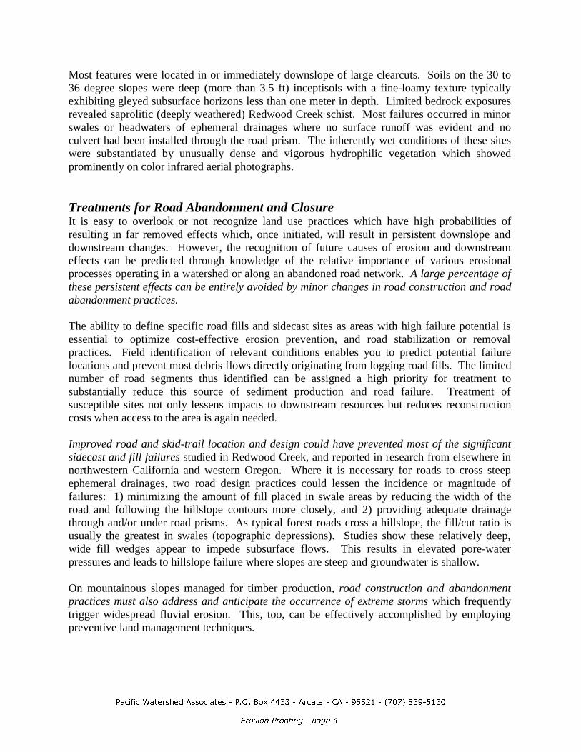
3DFLILF�:DWHUVKHG�$VVRFLDWHV���3�2��%R[��������$UFDWD���&$�������������������������
(URVLRQ�3URRILQJ���SDJH��
Most features were located in or immediately downslope of large clearcuts. Soils on the 30 to36 degree slopes were deep (more than 3.5 ft) inceptisols with a fine-loamy texture typicallyexhibiting gleyed subsurface horizons less than one meter in depth. Limited bedrock exposuresrevealed saprolitic (deeply weathered) Redwood Creek schist. Most failures occurred in minorswales or headwaters of ephemeral drainages where no surface runoff was evident and noculvert had been installed through the road prism. The inherently wet conditions of these siteswere substantiated by unusually dense and vigorous hydrophilic vegetation which showedprominently on color infrared aerial photographs.
Treatments for Road Abandonment and ClosureIt is easy to overlook or not recognize land use practices which have high probabilities ofresulting in far removed effects which, once initiated, will result in persistent downslope anddownstream changes. However, the recognition of future causes of erosion and downstreameffects can be predicted through knowledge of the relative importance of various erosionalprocesses operating in a watershed or along an abandoned road network. A large percentage ofthese persistent effects can be entirely avoided by minor changes in road construction and roadabandonment practices.
The ability to define specific road fills and sidecast sites as areas with high failure potential isessential to optimize cost-effective erosion prevention, and road stabilization or removalpractices. Field identification of relevant conditions enables you to predict potential failurelocations and prevent most debris flows directly originating from logging road fills. The limitednumber of road segments thus identified can be assigned a high priority for treatment tosubstantially reduce this source of sediment production and road failure. Treatment ofsusceptible sites not only lessens impacts to downstream resources but reduces reconstructioncosts when access to the area is again needed.
Improved road and skid-trail location and design could have prevented most of the significantsidecast and fill failures studied in Redwood Creek, and reported in research from elsewhere innorthwestern California and western Oregon. Where it is necessary for roads to cross steepephemeral drainages, two road design practices could lessen the incidence or magnitude offailures: 1) minimizing the amount of fill placed in swale areas by reducing the width of theroad and following the hillslope contours more closely, and 2) providing adequate drainagethrough and/or under road prisms. As typical forest roads cross a hillslope, the fill/cut ratio isusually the greatest in swales (topographic depressions). Studies show these relatively deep,wide fill wedges appear to impede subsurface flows. This results in elevated pore-waterpressures and leads to hillslope failure where slopes are steep and groundwater is shallow.
On mountainous slopes managed for timber production, road construction and abandonmentpractices must also address and anticipate the occurrence of extreme storms which frequentlytrigger widespread fluvial erosion. This, too, can be effectively accomplished by employingpreventive land management techniques.
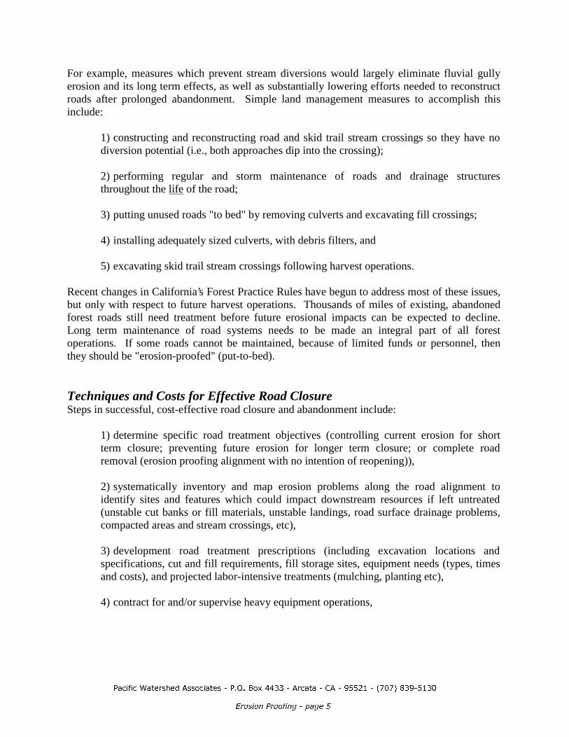
3DFLILF�:DWHUVKHG�$VVRFLDWHV���3�2��%R[��������$UFDWD���&$�������������������������
(URVLRQ�3URRILQJ���SDJH��
For example, measures which prevent stream diversions would largely eliminate fluvial gullyerosion and its long term effects, as well as substantially lowering efforts needed to reconstructroads after prolonged abandonment. Simple land management measures to accomplish thisinclude:
1) constructing and reconstructing road and skid trail stream crossings so they have nodiversion potential (i.e., both approaches dip into the crossing);
2) performing regular and storm maintenance of roads and drainage structuresthroughout the life of the road;
3) putting unused roads "to bed" by removing culverts and excavating fill crossings;
4) installing adequately sized culverts, with debris filters, and
5) excavating skid trail stream crossings following harvest operations.
Recent changes in California’s Forest Practice Rules have begun to address most of these issues,but only with respect to future harvest operations. Thousands of miles of existing, abandonedforest roads still need treatment before future erosional impacts can be expected to decline.Long term maintenance of road systems needs to be made an integral part of all forestoperations. If some roads cannot be maintained, because of limited funds or personnel, thenthey should be "erosion-proofed" (put-to-bed).
Techniques and Costs for Effective Road ClosureSteps in successful, cost-effective road closure and abandonment include:
1) determine specific road treatment objectives (controlling current erosion for shortterm closure; preventing future erosion for longer term closure; or complete roadremoval (erosion proofing alignment with no intention of reopening)),
2) systematically inventory and map erosion problems along the road alignment toidentify sites and features which could impact downstream resources if left untreated(unstable cut banks or fill materials, unstable landings, road surface drainage problems,compacted areas and stream crossings, etc),
3) development road treatment prescriptions (including excavation locations andspecifications, cut and fill requirements, fill storage sites, equipment needs (types, timesand costs), and projected labor-intensive treatments (mulching, planting etc),
4) contract for and/or supervise heavy equipment operations,

3DFLILF�:DWHUVKHG�$VVRFLDWHV���3�2��%R[��������$UFDWD���&$�������������������������
(URVLRQ�3URRILQJ���SDJH��
5) apply the most cost-effective hand-labor erosion control and revegetation treatmentsto sites which were disturbed during heavy equipment operations, and
6) fully document and evaluate the work effort (costs and hours) and results(effectiveness).
1. Determine objectives: The specific objectives set for road treatment affect all future workprescriptions and the level of road closure costs. For this reason, it is imperative to developmentconcise, clearly stated objectives that are within the available budget and accomplish the desiredresult. Three different types of objectives are listed above. Each implies differing levels ofeffort and expense.
2. Inventory potential erosion problems: Once objectives are set, sites along the road alignmentare inventoried (on erosion inventory forms) and mapped on aerial photos. Collectedinformation includes a site number, the location of the site, nature of the erosion problem(potential landslide, fill failure, stream crossing, etc.), the volume of erosion likely to occur inthe future, the amount expected to be delivered to a stream (if any), the likelihood the erosionwill actually occur (erosion potential), an evaluation of its treatability, and the heavy equipmentand labor-intensive work prescriptions (including expected times and excavation volumes)needed to solve the problem or prevent it from occurring.
The location of all existing and potential erosion problems along the road alignment must beclearly identified, described and quantified. Using a standardized data form, the informationfrom each site can be input to a database program, compared with other sites and prioritizedaccording to the need for the treatment and the projected cost-effectiveness of performing thework.
Erosion problems along the road are differentiated according to whether or not they: 1) threatenthe future integrity of the roadbed, 2) threaten to damage dowstream resources throughincreased sedimentation, or 3) both. The volume of potential future erosion at each potentialwork site must then be quantified to finally determine the cost-effectiveness of treatment areasalong the road alignment. Those possible treatments that are not cost-effective, or otherwiserequired, become lower priority elements of the road closure plan. Erosion problem areas andwork sites that would, if left untreated, severely damage the road or cause downstreamsedimentation become high priority for treatment.
3. Develop treatment prescriptions: The third step in a cost-effective road closure plan is todevelop specific heavy equipment prescriptions and to implement the erosion control anderosion prevention work at the selected work sites. It is very likely that most road segments willrequire intensive treatment at only a few locations. The remainder of the alignment may requirevery little work to prevent future erosion and maintain the integrity of the roadbed. Thus mostor the road bed may be left largely intact.
There are seven basic heavy equipment techniques used for road closure or road removal (Table1). Typical road treatments include (from least intensive to most intensive) surface
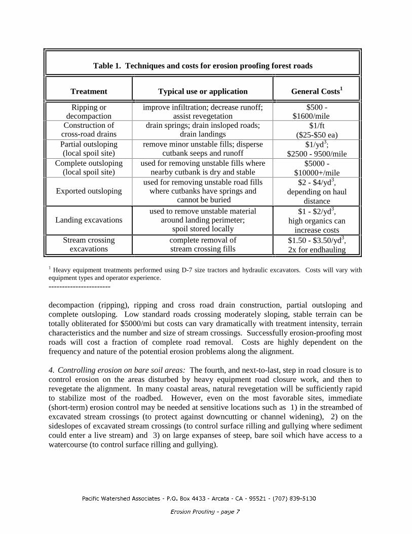
3DFLILF�:DWHUVKHG�$VVRFLDWHV���3�2��%R[��������$UFDWD���&$�������������������������
(URVLRQ�3URRILQJ���SDJH��
Table 1. Techniques and costs for erosion proofing forest roads
Treatment Typical use or application General Costs1
Ripping ordecompaction
improve infiltration; decrease runoff;assist revegetation
$500 -$1600/mile
Construction ofcross-road drains
drain springs; drain insloped roads;drain landings
$1/ft($25-$50 ea)
Partial outsloping(local spoil site)
remove minor unstable fills; dispersecutbank seeps and runoff
$1/yd3;$2500 - 9500/mile
Complete outsloping(local spoil site)
used for removing unstable fills wherenearby cutbank is dry and stable
$5000 -$10000+/mile
Exported outslopingused for removing unstable road fills
where cutbanks have springs and cannot be buried
$2 - $4/yd3,depending on haul
distance
Landing excavationsused to remove unstable material
around landing perimeter;spoil stored locally
$1 - $2/yd3,high organics can
increase costsStream crossing
excavationscomplete removal ofstream crossing fills
$1.50 - $3.50/yd3,2x for endhauling
1 Heavy equipment treatments performed using D-7 size tractors and hydraulic excavators. Costs will vary withequipment types and operator experience.-----------------------
decompaction (ripping), ripping and cross road drain construction, partial outsloping andcomplete outsloping. Low standard roads crossing moderately sloping, stable terrain can betotally obliterated for $5000/mi but costs can vary dramatically with treatment intensity, terraincharacteristics and the number and size of stream crossings. Successfully erosion-proofing mostroads will cost a fraction of complete road removal. Costs are highly dependent on thefrequency and nature of the potential erosion problems along the alignment.
4. Controlling erosion on bare soil areas: The fourth, and next-to-last, step in road closure is tocontrol erosion on the areas disturbed by heavy equipment road closure work, and then torevegetate the alignment. In many coastal areas, natural revegetation will be sufficiently rapidto stabilize most of the roadbed. However, even on the most favorable sites, immediate(short-term) erosion control may be needed at sensitive locations such as 1) in the streambed ofexcavated stream crossings (to protect against downcutting or channel widening), 2) on thesideslopes of excavated stream crossings (to control surface rilling and gullying where sedimentcould enter a live stream) and 3) on large expanses of steep, bare soil which have access to awatercourse (to control surface rilling and gullying).
3DFLILF�:DWHUVKHG�$VVRFLDWHV���3�2��%R[��������$UFDWD���&$�������������������������
(URVLRQ�3URRILQJ���SDJH��
Most of these erosion control practices are performed using hand labor, perhaps with someequipment assistance. The costs and general effectiveness of these techniques have beendocumented for steeplands in the Redwood Creek basin and elsewhere (Weaver and Sonnevil, 1984).A summary table of costs and cost-effectiveness, and technical specifications is available from theauthor.
5. Monitoring and documentation: The fifth and final step in the road closure process consists ofpost-project documentation of work (rates and volumes) and costs (labor and equipment hours foreach job element). Quantitative documentation is critical to derive cost estimates for future work, toimprove the cost-effectiveness of work prescriptions and to justify future projects based on acomparison with typical costs of road reconstruction where road closure has not been performed.Photographic documentation can also be a valuable tool for training future equipment operators inthe techniques for road closure.
ConclusionIt is no longer enough to close roads by simply closing the gate or blocking the road. Specifictechniques are available to successfully prevent road- and landing-related debris flows, to prevent orcorrect stream diversions (the leading cause of serious gullying in many areas), to prevent streamcrossing washouts, to prevent fill failures and to dewater gullies and landslides fed by road runoff.Existing Forest Practice Rules already specify employing such preventive practices for stabilizingnew temporary roads.
Planned, systematic road closure can be an inexpensive and successful technique for minimizinglong term resource damage caused by roads built in steepland areas. It provides land managers withthe opportunity to permanently prevent or control the majority of post-construction road-relatederosion, and its associated on-site and downstream impacts. Implementing technically sound roadclosure practices also minimizes structural damage to widespread, expensive forest road networksthat cannot be economically maintained for the long time period between harvest rotations.