research on photovoltaic grid-connected generation system
TRANSCRIPT
Research on Photovoltaic Grid-Connected Generation System
YANG Shu-ying1,a, WU Li-hong2,b and LIU Zhao-xia3,c
1Department of Electrical Engineering, North China Electric Power University, Baoding, China
2.3.Department of Electrical Engineering, North China Electric Power University, Baoding, China
[email protected], [email protected]
Keywords: Grid-connected inverter, Photovoltaic, Maximum power tracking control(MPPT)
Abstract. This dissertation researches on photovoltaic grid-connected generation system.
Photovoltaic grid-connected generation system has two core parts which are maximum power
tracking control(MPPT) of photovoltaic cells and the control of the grid-connected inverter.
Firstly,this paper introduces the operational principle and performance characteristic of photovoltaic
cells,and describes the equivalent circuit and mathematical model. Secondly,this paper introduces
several traditional MPPT control algorithms. Based on the maximum power of the fast track process
and stability, an improved intermittent scan method is designed to implement the maximum power
output in the photovoltaic grid-connection generation system and improve system performance and
maximum power point tracking speed. Finally, this dissertation analyses the targets of grid-
connected inverter control and studies the control strategies, and then designs mathematical model
of control system in photovoltaic grid-connected voltage/current inverter based on Sinusoidal Pulse
Width Modulation (SPWM).
Introduction
With the situation of energy resource crisis and the problem of circumstance pollution become more
and more severity, exploitation and utilization the clean and regeneration energy resource is
imperative. Solar energy is one of the most clean,practical and large scale regeneration energy
resources. The whole world focuses on the use of Photovoltaic(PV).The PV grid-connected system
will be the main utilization of solar energy, so it will be developed rapidly. Furthermore, with the
development of high-performance Digital Signal Processor (DSP)chip, it is possible that some most
advanced control strategies can be used to the PV grid-connected system. Under this background,
the dissertation deeply researches the PV grid-connected inverter. It has significance to research on
the PV grid-connected system.
The operational principle and performance characteristic of photovoltaic cell
The operational principle of photovoltaic cells bases on the photovoltaic effect of semiconductor
PN junction. The so-called photovoltaic effect, that is, when the object is irradiated by light,
electromotive force and electric current will generated with the changes of charge distribution in the
object. When sunlight or other light irradiates semiconductor PN junction, the voltage which was
commonly known as photovoltaic voltage will be generated between the two sides of the PN
junction, so that the short-circuit current will be generated when the PN junction in short circuit.
The phenomenon is well-known photovoltaic effect.
Equivalent Circuit and Mathematical Model of photovoltaic cell. In order to describe the
working status of the cells, an equivalent circuit offen is used to simulate the cells and load systems.
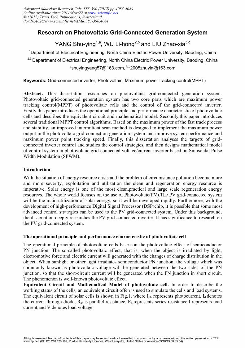
The equivalent circuit of solar cells is shown in Fig.1, where Iph represents photocurrent, Id denotes
the current through diode, Rsh is parallel resistance, Rs represents series resistance,I represents load
current,and V denotes load voltage.
Advanced Materials Research Vols. 383-390 (2012) pp 4084-4089Online available since 2011/Nov/22 at www.scientific.net© (2012) Trans Tech Publications, Switzerlanddoi:10.4028/www.scientific.net/AMR.383-390.4084
All rights reserved. No part of contents of this paper may be reproduced or transmitted in any form or by any means without the written permission of TTP,www.ttp.net. (ID: 128.210.126.199, Purdue University Libraries, West Lafayette, United States of America-03/10/13,08:35:54)
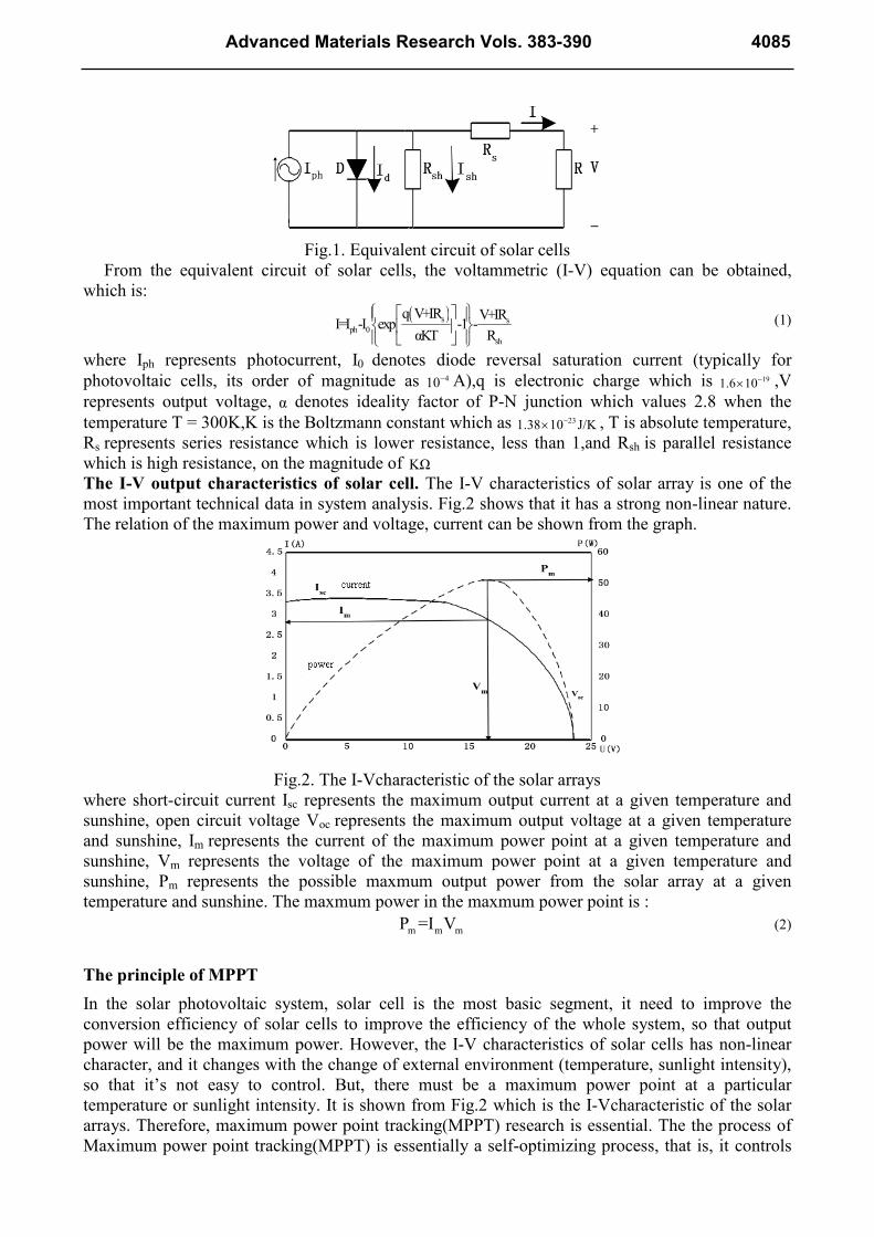
Fig.1. Equivalent circuit of solar cells
From the equivalent circuit of solar cells, the voltammetric (I-V) equation can be obtained,
which is:
( )s sph 0
sh
q V+IR V+IRI=I -I exp -1 -
αKT R
(1)
where Iph represents photocurrent, I0 denotes diode reversal saturation current (typically for
photovoltaic cells, its order of magnitude as 410− A),q is electronic charge which is 191.6 10−× ,V
represents output voltage, α denotes ideality factor of P-N junction which values 2.8 when the
temperature T = 300K,K is the Boltzmann constant which as 231.38 10 J/K−× , T is absolute temperature,
Rs represents series resistance which is lower resistance, less than 1,and Rsh is parallel resistance
which is high resistance, on the magnitude of KΩ
The I-V output characteristics of solar cell. The I-V characteristics of solar array is one of the
most important technical data in system analysis. Fig.2 shows that it has a strong non-linear nature.
The relation of the maximum power and voltage, current can be shown from the graph.
Fig.2. The I-Vcharacteristic of the solar arrays
where short-circuit current Isc represents the maximum output current at a given temperature and
sunshine, open circuit voltage Voc represents the maximum output voltage at a given temperature
and sunshine, Im represents the current of the maximum power point at a given temperature and
sunshine, Vm represents the voltage of the maximum power point at a given temperature and
sunshine, Pm represents the possible maxmum output power from the solar array at a given
temperature and sunshine. The maxmum power in the maxmum power point is :
m m mP =I V (2)
The principle of MPPT
In the solar photovoltaic system, solar cell is the most basic segment, it need to improve the
conversion efficiency of solar cells to improve the efficiency of the whole system, so that output
power will be the maximum power. However, the I-V characteristics of solar cells has non-linear
character, and it changes with the change of external environment (temperature, sunlight intensity),
so that it’s not easy to control. But, there must be a maximum power point at a particular
temperature or sunlight intensity. It is shown from Fig.2 which is the I-Vcharacteristic of the solar
arrays. Therefore, maximum power point tracking(MPPT) research is essential. The the process of
Maximum power point tracking(MPPT) is essentially a self-optimizing process, that is, it controls
Advanced Materials Research Vols. 383-390 4085
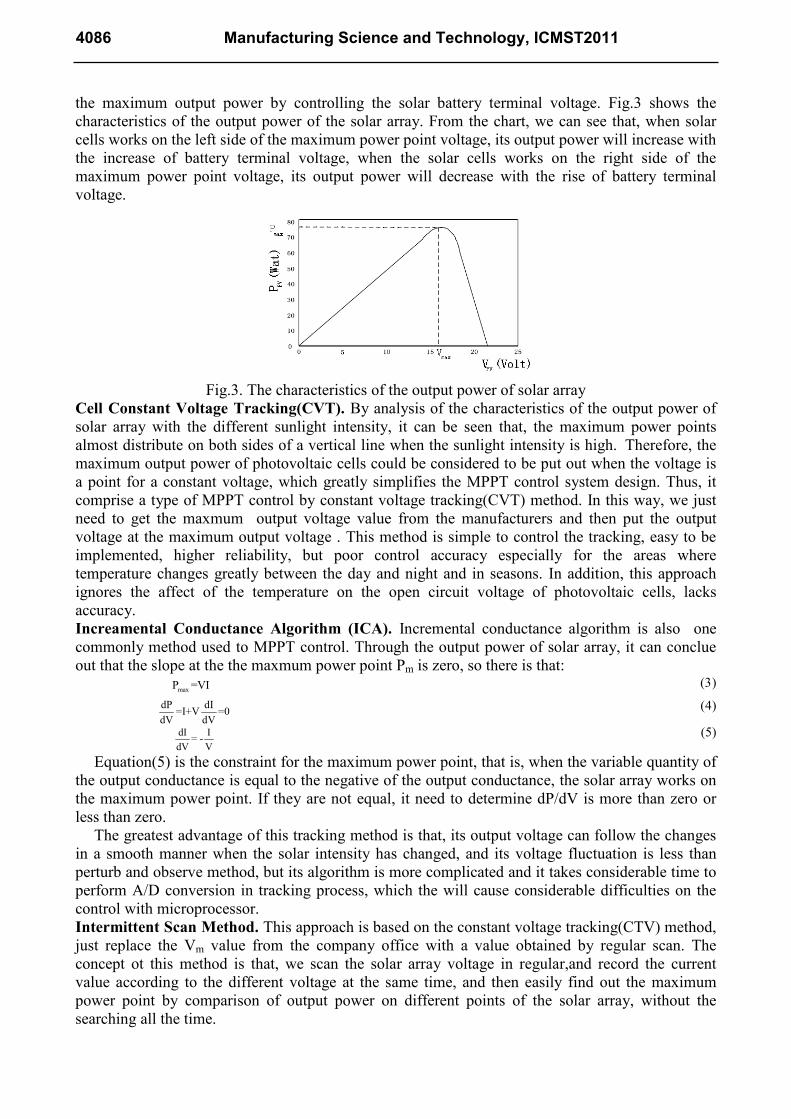
the maximum output power by controlling the solar battery terminal voltage. Fig.3 shows the
characteristics of the output power of the solar array. From the chart, we can see that, when solar
cells works on the left side of the maximum power point voltage, its output power will increase with
the increase of battery terminal voltage, when the solar cells works on the right side of the
maximum power point voltage, its output power will decrease with the rise of battery terminal
voltage.
Fig.3. The characteristics of the output power of solar array
Cell Constant Voltage Tracking(CVT). By analysis of the characteristics of the output power of
solar array with the different sunlight intensity, it can be seen that, the maximum power points
almost distribute on both sides of a vertical line when the sunlight intensity is high. Therefore, the
maximum output power of photovoltaic cells could be considered to be put out when the voltage is
a point for a constant voltage, which greatly simplifies the MPPT control system design. Thus, it
comprise a type of MPPT control by constant voltage tracking(CVT) method. In this way, we just
need to get the maxmum output voltage value from the manufacturers and then put the output
voltage at the maximum output voltage . This method is simple to control the tracking, easy to be
implemented, higher reliability, but poor control accuracy especially for the areas where
temperature changes greatly between the day and night and in seasons. In addition, this approach
ignores the affect of the temperature on the open circuit voltage of photovoltaic cells, lacks
accuracy.
Increamental Conductance Algorithm (ICA). Incremental conductance algorithm is also one
commonly method used to MPPT control. Through the output power of solar array, it can conclue
out that the slope at the the maxmum power point Pm is zero, so there is that:
maxP =VI (3)
dP dI=I+V =0
dV dV
(4)
dI I= -
dV V
(5)
Equation(5) is the constraint for the maximum power point, that is, when the variable quantity of
the output conductance is equal to the negative of the output conductance, the solar array works on
the maximum power point. If they are not equal, it need to determine dP/dV is more than zero or
less than zero.
The greatest advantage of this tracking method is that, its output voltage can follow the changes
in a smooth manner when the solar intensity has changed, and its voltage fluctuation is less than
perturb and observe method, but its algorithm is more complicated and it takes considerable time to
perform A/D conversion in tracking process, which the will cause considerable difficulties on the
control with microprocessor.
Intermittent Scan Method. This approach is based on the constant voltage tracking(CTV) method,
just replace the Vm value from the company office with a value obtained by regular scan. The
concept ot this method is that, we scan the solar array voltage in regular,and record the current
value according to the different voltage at the same time, and then easily find out the maximum
power point by comparison of output power on different points of the solar array, without the
searching all the time.
4086 Manufacturing Science and Technology, ICMST2011
This intermittent scan method need only milliseconds (5-10ms)to determine, while the time of
the regular scan could extend to second grade. We should calculat the maximum power and the
mathching voltage Vm with a specific light intensity and temperature by scanning and control the
output of the Pulse Width Modulation(PWM), so that we can make the system work on the point
according to the Vm . This approach generally does not cause swing.
The MPPT of the photovoltaic grid-connected inverter
To find out the best MPPT control method, we should not only compare the advantages and
disadvantages of each method, but also select the optimal algorithm of the topology and load
characteristics of the photovoltaic system according to the actual applications. We assume that the
system uses two grid-connected inverter, MPPT is implemented at the first stage of transformation,
and the control of connecting grid and other controls are implemented at the second stage of
transformation, so that we reduce the complexity of controls and increase the accuracy of each stage
control.
Targets of Photovoltaic Grid-connected inverter control. Photovoltaic system is a device which
transforms direct current (DC) from the solar panels into alternating current(AC) and then supply
power to the power system. It is actually an active inverter system. The target of the photovoltaic
grid-connected control is that: control the output alternating current from the inverter to be the
stable, high-quality sine wave and the AC must be the same frequency, phase with the net voltage.
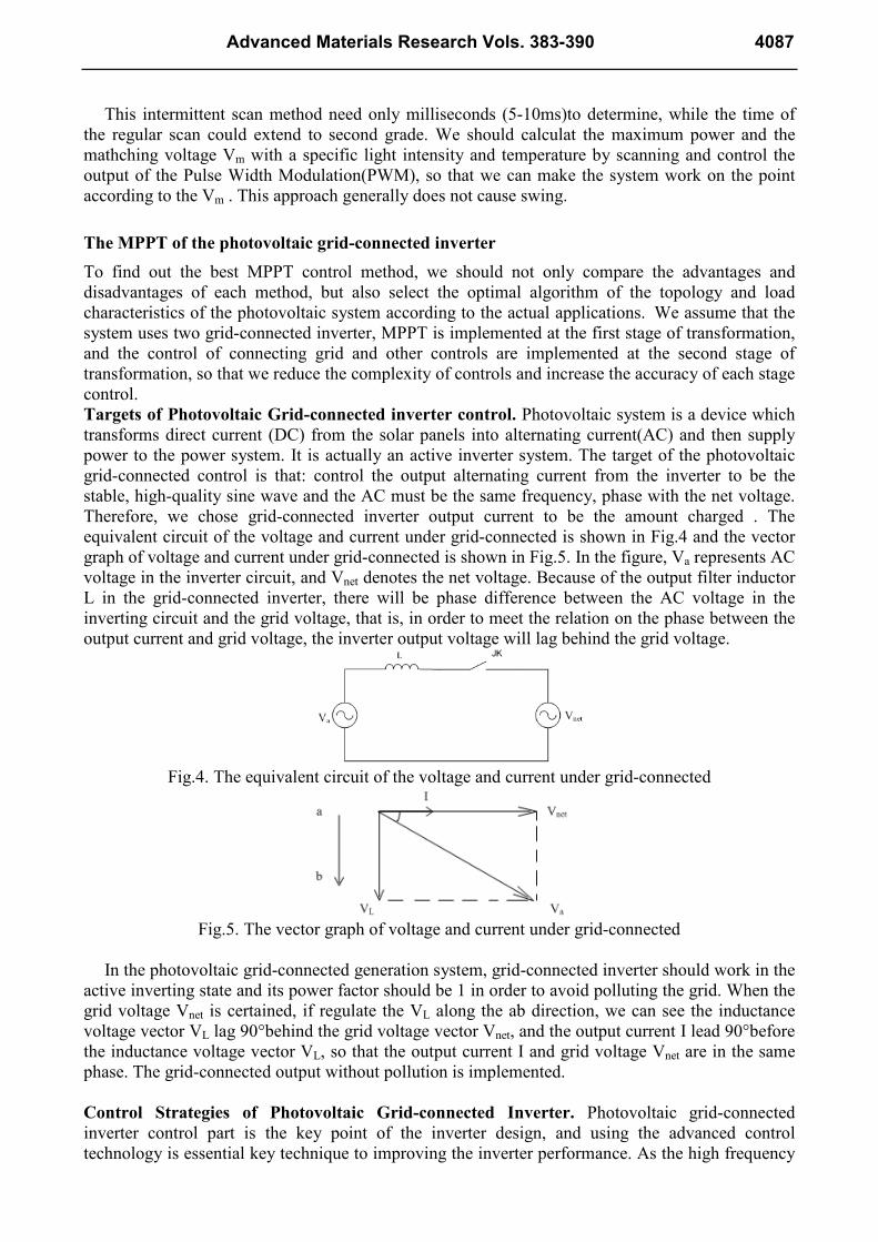
Therefore, we chose grid-connected inverter output current to be the amount charged . The
equivalent circuit of the voltage and current under grid-connected is shown in Fig.4 and the vector
graph of voltage and current under grid-connected is shown in Fig.5. In the figure, Va represents AC
voltage in the inverter circuit, and Vnet denotes the net voltage. Because of the output filter inductor
L in the grid-connected inverter, there will be phase difference between the AC voltage in the
inverting circuit and the grid voltage, that is, in order to meet the relation on the phase between the
output current and grid voltage, the inverter output voltage will lag behind the grid voltage.
Fig.4. The equivalent circuit of the voltage and current under grid-connected
Fig.5. The vector graph of voltage and current under grid-connected
In the photovoltaic grid-connected generation system, grid-connected inverter should work in the
active inverting state and its power factor should be 1 in order to avoid polluting the grid. When the
grid voltage Vnet is certained, if regulate the VL along the ab direction, we can see the inductance
voltage vector VL lag 90°behind the grid voltage vector Vnet, and the output current I lead 90°before
the inductance voltage vector VL, so that the output current I and grid voltage Vnet are in the same
phase. The grid-connected output without pollution is implemented.
Control Strategies of Photovoltaic Grid-connected Inverter. Photovoltaic grid-connected
inverter control part is the key point of the inverter design, and using the advanced control
technology is essential key technique to improving the inverter performance. As the high frequency
Advanced Materials Research Vols. 383-390 4087
of power electronic devices and the increase of the computing speed of the microprocessor,
especially with the emerge of high-performance digital signal processor (DSP), it is possible to use
advanced control strategies into the photovoltaic grid-connected control.
At present, the program widely used in the photovoltaic grid-connected generation system is
that: firstly, transform the solar energy into electric energy form; secondly, a djust the electric
energy into DC voltage which meets the requirements of full-bridge SPWM inverter; finally,
convert solar energy back to the AC power system though the full-bridge SPWM inverter. The
leading section in the whole system is the inverter, in which we use the SPWM inverting
technology. In order to reduce the grid-connected devices’ impacts in the grid-connected operating,
the network inverter should meet the following conditions according to qualifications of granted
cycle parallelling of the power system:
• Inverter output voltage should be about equal to the grid voltage, and the general error should
be within 10%;
• Inverter output frequency should be close to the grid frequency, and the general frequency
error should be no more than 0.4Hz;
• Inverter output voltage and grid voltage should be the same phase, and the general phase error
should be no more than 10 degrees.
Therefore, the control system need to accomplish the following tasks:
• Collect analogues such as DC,AC voltage and current used to monitor and control;
• Provide the SPWM signals whose pulse width and frequency can be changed from time to time
to the power device driver;
• Detect the frequency of the grid voltage and the phase should be digital phase-locked;
• Receive the protection signals such an over-current, over-voltage, and implement automatic
protection.
Conclusions
In the photovoltaic grid-connected generation system, solar cell is the most basic segment, It must
to improve the solar cell conversion efficiency to improve the efficiency of the whole system, which
makes the output power to be the maximum efficiency. This paper introduces the constant voltage
tracking(CVT), the incremental conductance algorithm(ICA), intermittent scan method and so. This
paper focuses on the maxmum power point tracking(MPPT) of the photovoltaic grid-connected
inverter, studies the control targets and control strategies, and finally designs mathematical model
of control system in photovoltaic grid-connected voltage/current inverter based on Sinusoidal Pulse
Width Modulation (SPWM).
References
[1] Yeong-Chau Kuo, Tsorng-Juu Liang, Jiann-Fuh Chen Novel: "Maximum Power Point Tracking
Controller for Photovoltaic Energy Conversion System". IEEE Transactions on Industrial
Electronics.Vol.48, No.3,2001, pp594-601
[2] Zmood D N,Holmes D G: "Stationary frame current regulation of PWM inverters with zero
steady-state error".IEEE Transactions on Power Electronics, 2003,18(3):814-822
[3] Eftichios koutroulis, Kostas kalaitza kis, Nicholas C.Voulgaris: " Development of a
Microcontroller-Based, Photovoltaic Maximum Power Point Tracking Control System".IEEE
Transactions on Power Electrics.Vol.16,No.1,Jan 2001,pp46-54
4088 Manufacturing Science and Technology, ICMST2011

[4] Toshihiko Noguchi, Shigenori Togashi, and Ryo Nakamoto: "Short-Current Photovoltaic and
Converter Module System".IEEE Transactions on Industrial Electronics.Vol.49,No.1
2002,pp217-223
[5] Xuejun Liu,Luiz A.C.Lopes. "An Improved Perturbation and Observation Maximum Power
Point Tracking Algorthm for PV arrays". 2004 35th
Annul IEEE Power Electronics Specialists
Conference, Vol.3,2004,pp2005-2010
[6] Kojabadi H M, Bin Yu, Gadoura I A,et al. "A novel DSP-based current-controlled PWM
strategy for single phase grid connected inverter".IEEE Transactions on Power Electronics,
2006,21(4):985-993
Advanced Materials Research Vols. 383-390 4089

Manufacturing Science and Technology, ICMST2011 10.4028/www.scientific.net/AMR.383-390 Research on Photovoltaic Grid-Connected Generation System 10.4028/www.scientific.net/AMR.383-390.4084
DOI References
[6] Kojabadi H M, Bin Yu, Gadoura I A, et al. A novel DSP-based current-controlled PWM strategy for
single phase grid connected inverter,. IEEE Transactions on Power Electronics, 2006, 21(4): 985-993.
http://dx.doi.org/10.1109/TPEL.2006.876851