research article radio-wave propagation in salt domes...
TRANSCRIPT
Research ArticleRadio-Wave Propagation in Salt Domes: Implications fora UHE Cosmic Neutrino Detector
Alina-Mihaela Badescu1 and Alexandra Saftoiu2
1 University Politehnica of Bucharest, Boulevard Iuliu-Maniu, No. 1-3, Bucharest, Romania2 IFIN-Horia Hulubei, Strada Reactorului No. 30, P.O. Box MG-6, Bucharest-Magurele, Romania
Correspondence should be addressed to Alina-Mihaela Badescu; [email protected]
Received 3 September 2013; Revised 21 December 2013; Accepted 24 December 2013; Published 20 January 2014
Academic Editor: Mehmet Bektasoglu
Copyright © 2014 A.-M. Badescu and A. Saftoiu.This is an open access article distributed under theCreativeCommonsAttributionLicense, which permits unrestricted use, distribution, and reproduction in anymedium, provided the originalwork is properly cited.The publication of this article was funded by SCOAP3.
Salt deposits can be used as a natural dielectric medium for a UHE cosmic neutrino radio detector. Such a detector relies on thecapability of reconstructing the initial characteristics of the cosmic neutrino from the measured radio electrical field produced atneutrino’s interaction in salt by the subsequent particle shower. A rigorous characterization of the propagation medium becomescompulsory. It is shown here that the amplitude of the electric field vector is attenuated by almost 90% after 100m of propagation ina typical salt rock volume.The heterogeneities in salt also determine the minimal uncertainty (estimated at 19%) and the resolutionof the detector.
1. Introduction
Ultra high energy neutrinos can be a proof of the theoreticalupper limit on the energy of cosmic rays fromdistant sources,play an important role in the Big Bang scenario, and alsounveil the mystery of the cosmic accelerator (pulsars, activegalactic nuclei, etc.). In the same time they travel undeflectedby intervening magnetic fields and interact very weakly. Thismakes their observation a scientifical and technical challenge.
A cosmic neutrino detector images the sky using interac-tions of a nearly massless subatomic particle called neutrino.Neutrinos are weakly interacting particles that cannot bedetected directly. Their properties are deduced by analyzingthe showers resulted from their interaction with nuclei in themedium.
One detection method was proposed by Askaryan [1].He suggested that if a particle, including neutrinos, interactswithin a volume of dielectric, a broadband electromagnetic(EM) field (including radio frequencies), that can be mea-sured, will be generated. In order to compensate for the smallinteraction probability of the neutrino [2], a huge volume ofdetecting material is required that can be found in naturaldielectric volumes, such as the ice sheets at the poles ornatural salt domes. The medium should be transparent forthe produced waves to ensure large propagation distances.
Thus, ice can serve as the detecting medium for optical andradio waves (an example is the IceCube detector [3] that usesphotomultipliers tomeasure the EMfield) and salt—for radiowaves. The latter was tested at Stanford Linear Acceleratorwhere radio waves from high energy particles interacting insynthetic rock salt were detected [4].
One of the key problems associated with a neutrinoradio detector in salt is the capability of reconstructing thecharacteristics of the cosmic neutrinos that interact in thesalt volume frommeasurements of the radio radiation whichresulted in their interaction. Detection can be performedusing arrays of (standard) radio antennas placed in boreholes:the more transparent the medium, the larger the usabledistance between antennas.The radio waves produced by theneutrino-induced shower travel through salt so the prop-agation medium has a huge impact on measurements andresults. Most of the medium’s properties can be describedusing the relative permittivity. In order to achieve the highestdetection performances, antennas should be placed awayfrom the periphery of the dome (including its cap rock).
The existing optical neutrino detector at the South PoleIceCube pointed out serious problems in detection and dataanalysis due to the effects that the nonideal medium hason wave propagation. A detailed study of the properties ofthe glacial ice at the South Pole has been performed by the
Hindawi Publishing CorporationAdvances in High Energy PhysicsVolume 2014, Article ID 901434, 9 pageshttp://dx.doi.org/10.1155/2014/901434
2 Advances in High Energy Physics
AMANDA collaboration [5].They found that ice is very clearin the optical and near UV regions but both scattering andabsorption are strongly depth dependent. At each 10m depthinterval, the effective scattering and absorption lengths as afunction of wavelength were determined.
In this work, we investigate the possibility of detectingcosmic neutrinos in salt by measuring and analyzing theirinteraction products: radio waves [6, 7]. Radio waves are theresult of the Askaryan effect [1]. The broadband frequencyspectrum peaks at a few GHz, but due to several reasons(attenuation, temperature dependence, etc.) we decided toselect an operating frequency of about 200MHz [6]. Aswavespropagate in a nonideal medium before being measured, it ismandatory to have first a good geophysical material descrip-tion for radio waves propagation. Hapke already remarkedthat this regime is not well understood [8]. It was suggestedthat an effective-medium theory should be applied to calcu-late the permittivity.
The influence of the medium can be quantified bytransmission—a parameter that incorporates all propagationeffects (more details are given in Section 3). Transmissionshould be estimated because the data to be analyzed—forexample, measurements recorded by each antenna—is pro-portional to the product of transmission and the radio fieldgenerated at interaction. For the latter, the model in [9, 10]will be used.
One method to achieve medium characterization is bydownhole geophysical logging. This technique involvesinstalling sensing devices into a borehole to record physicalparameters thatmay be interpreted as specific rock character-istics.The geological mapping of undergroundmine workingand geological logging of core samples are insufficient tomake an identification of the internal structure of evaporites[11].
Another method to obtain information about the spa-tial variation in dielectric properties is ground penetratingradar. A pulse radar emits an electromagnetic pulse from adipole antenna into a rock and the returned signal containsreflections caused by subsurface contrasts in electromagneticimpedance. The travel time reflects the depth to the impe-dance contrasts [12].
The same issue—good geophysical material descriptionfor radio waves propagation—has been addressed by othertypes of applications: locating buried utilities [13–15], detect-ing buried land mines [16–18], profiling the subsurfaceof highway pavement, and so forth. Although theoreticalapproaches have been reported by [19, 20] and others, modelsfor propagation are rare because the heterogeneity in saltclearly affects radio waves. First tests on determining theattenuation length of a radio signal at 400 and 800MHz onsamples from the “Unirea” salt dome in Slanic Prahova,Romania, showed a large deviation from the ideal mediumcase [21]. The “Unirea” salt mine will be considered a conser-vative case. It was chosen in our analysis because we alreadyhave a working laboratory installed so we had access todifferent results concerning the purity of salt.
In the following we investigate and quantify the effectof the medium on wave propagation. In Section 2 we brieflyreview the geological properties of salt domes, includingmain
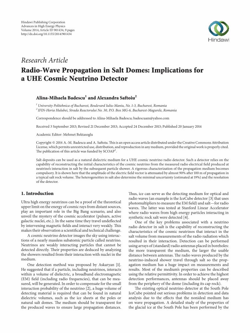
Figure 1: Genesis Room (54m height, 208m depth) of the “Unirea”salt mine, Slanic Prahova, Romania. Photo courtesy of © AndreiNiculescu.
heterogeneities and other factors that can affect propagation.In the next section, natural occurring impurities and mainheterogeneities in a salt dome and their effects on radiowave propagation are analyzed.The last part summarizes ourresults.
2. Geological Properties of Salt Mines
Rock salt deposits are widely distributed throughout theworld. The salt accumulations in Romania are among thelargest in Europe and thus construction of a neutrino detectorwould be well justified here. The salt that forms diapirs stud-ied here is EarlyMiocene in age [22]. In the following, we willonly refer toUnireamine, in Slanic Prahova (Romania), char-acterized by a domal folding structure (Figure 1).
This salt dome represents a gigantic plug that has risenupward diapirically, because of its low density, into the overly-ing strata [22]. Originally the sedimentary salt deposits wereat depths of several kilometers. Under hydrostatic pressure,the very plastic salt of lower density starts to flow upwardthrough sediments of greater density. Salt flow is controlledthrough the fault intersections resulting in a domal structure.The shape of the salt deposit depends on the specific condi-tions of its emplacement in geological environment (“Unirea”dome has a lenticular shape) [22].
Following [11], we considered four basic heterogeneousinternal structures of the salt deposits.
2.1. Domal Heterogeneity. The main characteristic of domalheterogeneity is the mixture of halite and anhydrite. Darkersalts owe their color to dissemination of anhydrite. Amixtureof salt and anhydrite can be found in various proportionsat short distance, which will result in extreme heterogeneity.Generally, the content of anhydrite in salt dome varies from1% to 80%.
The effect of the main domal heterogeneities (listed inTable 1) was simulated and their influence on the propertiesof the medium was presented in [23].
Advances in High Energy Physics 3
Table 1: Concentration of main impurities in Slanic Prahova mine,according to [38].
Al Ca Ti Fe V Mn Cu Br𝐶 [𝜇g/kg] 14.7 2190 2260 33 14.9 61.7 7.9 126
𝛼
Layer 2
Layer 1
Layer n
dL1
dL2𝛼t
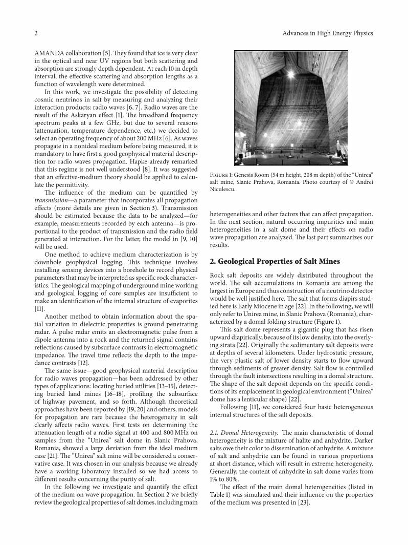
Figure 2: An unaltered sedimentary structure of a salt dome [23].The solid thin lines represent waves that propagate in each layer.Thedashed lines show the reflected ones. The thick solid line shows thewave that enters in a layer after multiple reflections.The thickness oflayer 𝑖 is 𝑑
𝐿𝑖.
2.2. Sedimentary Heterogeneity. On ancient oceans bottoms,layers of sediment were deposited as a sequence of horizontalbeds. An unaltered sedimentary structure of a dome isrepresented by a column of various beds which could begrouped in function of their chemical composition or facialdevelopment (Figure 2) [11].Thick sedimentary beds are clas-sified as relatively homogeneous, nondispersive, isotropic,and linear medium. In this model, we ignored interbeddedlayers as they are not a common feature in salt diapirs. Thetransmission coefficient 𝜏 due towave propagation from layer1 to layer 3 (that is the fraction of wave energy that reacheslayer 3) is given by [24]
𝜏 = |𝑤|2, (1)
where 𝑤 is
𝑤 =1 − 𝑟2
12
exp (−𝑖Ψ) − 𝑟212exp (𝑖Ψ)
, (2)
with
Ψ =𝜔
𝑐ℎ2√𝜀𝑟2− sin2𝛼 (3)
being a measure of the absorption in medium 2; ℎ2is the
height of the second medium (layer’s thickness), 𝜀𝑟2
is thepermittivity of medium 2, and 𝛼 is the incidence angle withrespect to the normal (Figure 2).
The coefficient 𝑟12
describes the reflections at the firstinterface. If one considers nonpolarized waves, then
𝑟 =𝑟12𝑠+ 𝑟12𝑝
2, (4)
where 𝑟12𝑠,𝑝
is the ratio of the amplitudes of the reflected elec-tric field to the incident one when the field vector is perpen-dicular (index 𝑠)/parallel (index 𝑝) to the propagation plane.The reflection coefficients are given by [8]
𝑟12𝑠=2 cos𝛼
cos𝛼 + 𝑚 cos𝛼𝑡
,
𝑟12𝑝=2 cos𝛼
𝑚 cos𝛼 + cos𝛼𝑡
,
(5)
where 𝑚 is the ratio of the refractive indexes (the refractiveindex of a medium is defined as the square root of themedium’s permittivity) and𝛼
𝑡is the angle that the transmitted
wave makes with the normal at the interface with the secondmedium. It can be calculated using Snell’s law of refraction:
sin𝛼 = 𝑚 sin𝛼𝑡. (6)
If the permittivity is a complex number, 𝛼𝑡will also be
complex. The physical meaning of a complex number is aphase shift of the transmitted wave.
The sedimentary heterogeneity effect (the transmittedfraction from layer 1 to layer 𝑛) can be evaluated usingthe model described by (1)–(6). As shown in Figure 2, theelectromagnetic radiation crosses the first layer and only afraction of it enters the second layer.The reminder is reflectedand can be regarded as a loss. In order to show that the lossassumption is well justified, the power of the transmittedwaves in layer two (thick arrow in Figure 2) that resides aftermultiple reflections in layer 1 (dashed arrow in Figure 2) hasbeen calculated. As it is more than three orders of smallermagnitude it can be ignored [7].
2.3. Mineral Heterogeneity. With respect to mineral het-erogeneity, the spatial relationship between halite salts andpotassium salts is primarily important. The multimineraldevelopment is of a complex nature and is usually locatedat the boundary of a sedimentary basin. The developmentof potassium salts in a majority of cases occurs like a framearound the rock salt body.
Themineral heterogeneity will not be further investigatedin this paper, due to lack of experimental probes. For furtherprocessing, multiple samples should be collected from differ-ent locations and chemically analyzed. We estimate that thisheterogeneity (associated with peripheral areas of the dome)can be disregarded in the case of a neutrino detector sincedata acquisition will be made only in the central parts of thesalt block.
2.4. Structural Heterogeneities. Structural heterogeneities ofevaporated strata are the product of tectonic movements ofthe earth’s crust in the region of their deposition.
The structural heterogeneities in evaporated strata couldvary significantly due to differences in elasticity of individuallayers. For example, gypsum, anhydrite, marl, and othersmight have developed an apparent internal blocky structure.It is specific to cap rocks or other types of folding structuresand thus it will not represent a case study here.
4 Advances in High Energy Physics
Another geological property of a salt mine is the faultingstructures. A problem associated with the step faults is thatthey can be a water feeder to the salt deposits.
Investigations of radio wave propagation in salt are diffi-cult because a priori knowledge of the location of water- orbrine-bearing zones is seldom available.
Rock salt is a conductor for electric current mostly due tointernally contained water in the pores’ interstices. The waterinduced conductivity in rock salt can be determined usingthe model in [25]. The value for the conductivity induced bya 0.02% water content is 2 × 10⁻⁶Ω−1m−1 [26]. Such smallwater content is not expected to decrease significantly thetransmission in salt beds.
The effect of brines in forms of fluid inclusions was alsoestimated in [23]. The brine induced radio wave attenuationwas calculated following [27, 28]. If thewaves travel a distanceof 1.1 cm in brine, about 70% of their energy will be lost.If the distance increases to 1.4 cm, only 20% of energy willremain. For propagation distances larger than 2.1 cm, thetransmission coefficient will be smaller than 10%.
It is concluded that connate water and secondary trappedwater [11] will absorb all radio electromagnetic radiation.Location of such caverns must be determined a priori. Theycan be traced only experimentally (i.e., using GPR measure-ments, as suggested in [29]). Another groundwater sourcetracer can be achieved by chemical composition analysis (e.g.,a high MgCl
2content indicates connate water, the Cl/Br
coefficient-primary trapped water etc. [11]).
3. Propagation Studies
3.1. Effect of Heterogeneous Zones on Electromagnetic Waves.Pure sodium chloride is an isotropic crystal. Entering radi-ation is refracted at a constant angle and passes throughthe crystal at a single velocity without being polarized byinteraction with the electronic components of the crystallinelattice.Thus, for as long as impurities are in small number, onecan expect no birefringence phenomenon in all frequencybands.
The electromagnetic (EM) data observed in geophysicalexperiments in heterogeneous media generally reflect twophenomena: electromagnetic induction (EMI) in the earth andthe induced polarization (IP) effect related to the relaxation ofpolarized charges in rock formations. The IP effect is causedby the complex electrochemical reactions phenomena thataccompany current flow in the earth and it is manifestedby accumulating electric charges on the surface of differentgrains forming the rock.
EMI and IP phenomena occur in rock formations inareas of mineralization (areas withmineralized particles) andhydrocarbon reservoirs [30].
Areas of mineralization are observed in salt dome’s caprock.The cap rock is composedmainly of anhydrite, gypsum,and calcite arranged in heterogeneous layers. Cap rocklayering is irregular and varies greatly from dome to dome.Structural deformation and fracturing are common, as arecavernous voids. Analysis of other features as the locations ofkimberlites, faulting, including zones of mineralization, canbe determined from, for example, aeromagnetic data [31].
Salt is impermeable and when it reaches a layer of per-meable rock, in which hydrocarbons are migrating, it blocksthe pathway in much the same manner as a fault trap. Dueto that, the region around the perimeter of the salt dome is anideal geologic environment for hydrocarbon traps [32].
The fracturing of surrounding rocks due to the intrudingsalt and the lifting of the rocks above the salt dome alsoprovide an environment for the existence of fault traps andanticlinal traps in addition to the salt dome traps around theperimeter of the dome. A salt dome region, therefore, is anexcellent geologic environment for all types of traps [33].Moreover, association with evaporite minerals can provideexcellent sealing capabilities. The monitoring of reservoirproduction can be performed using EMmethods [34].
Since in the case of a cosmic neutrino detector the detect-ing elements are placed away from periphery of the dome, wecan conclude that neither EMI nor IP will affect radio wavepropagation. Moreover, these effects are important at kHzfrequencies, so observations at∼200MHzwill not be affected.
3.2. Radio Transmission Estimates. We consider long-rangepropagation of radio waves, which implies a large number ofcrossed sedimentary layers. For this purpose, we will intro-duce the transmission—that is, the ratio of the transmittedelectric field strength after propagation through the entire saltmedium to the initial electrical field strength. Absorption andscattering effects are also included in this quantity.
For the simulations presented in this paper, we consideredthe classical propagation model. We assumed that there areonly a forward and a backward traveling wave in each layer.A limitation of the model that would require further investi-gation is connected to the evanescent fields at the separationborders between layers which could react with the evanescentfields of adjacent layers.
In real situations, one can neither predict normeasure thepermittivities of all the salt layers (especially when the volumeof interest is of the order of cubic kilometers) and extendedinvasive procedures are not an option before excavatingthe boreholes. Thus, one should investigate the possibilityof approximating the real environment by considering an“equivalent permittivity” of the medium (given by the meanof the permittivities of the constituents layers, here consid-ered equal in size).The assumption of amedia build of homo-geneous layers with constant thickness does not fit the in situcharacteristics of a salt dome in most cases, but it is treatedhere as a conservative case.
To study the effect of the impurities on long-range prop-agation, we simulated a situation where only one impurityis changing its concentration from layer to layer. If thelayer to layer variations in concentration are small (about0.1𝐶element—where𝐶element is the concentration of the elementgiven in Table 1), the results are independent of the impuritytype that varies its concentration. This is due to the fact thatmost of the power is lost by reflections between layers whileabsorption and scattering due to impurities are very small.
Absorption remains small compared to reflections evenif layer to layer difference in concentration is large (about0.5𝐶element). The transmission is poorer for impurities ofhigher physical dimension. Most losses are associated with
Advances in High Energy Physics 5
0.94
0.93
0.92
0.91
0.910 20 30 40
Number of layers
(Et/Ei),
Br (
equi
vale
nt)
(a)
0.385
0.38
0.375
0.37
0.365
0.3610 20 30 40
Number of layers
(Et/Ei),
Br (
laye
red)
(b)
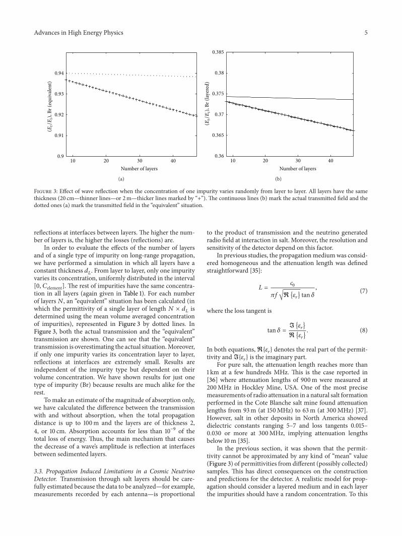
Figure 3: Effect of wave reflection when the concentration of one impurity varies randomly from layer to layer. All layers have the samethickness (20 cm—thinner lines—or 2m—thicker lines marked by “+”). The continuous lines (b) mark the actual transmitted field and thedotted ones (a) mark the transmitted field in the “equivalent” situation.
reflections at interfaces between layers. The higher the num-ber of layers is, the higher the losses (reflections) are.
In order to evaluate the effects of the number of layersand of a single type of impurity on long-range propagation,we have performed a simulation in which all layers have aconstant thickness 𝑑
𝐿. From layer to layer, only one impurity
varies its concentration, uniformly distributed in the interval[0, 𝐶element]. The rest of impurities have the same concentra-tion in all layers (again given in Table 1). For each numberof layers𝑁, an “equivalent” situation has been calculated (inwhich the permittivity of a single layer of length 𝑁 × 𝑑
𝐿is
determined using the mean volume averaged concentrationof impurities), represented in Figure 3 by dotted lines. InFigure 3, both the actual transmission and the “equivalent”transmission are shown. One can see that the “equivalent”transmission is overestimating the actual situation.Moreover,if only one impurity varies its concentration layer to layer,reflections at interfaces are extremely small. Results areindependent of the impurity type but dependent on theirvolume concentration. We have shown results for just onetype of impurity (Br) because results are much alike for therest.
Tomake an estimate of themagnitude of absorption only,we have calculated the difference between the transmissionwith and without absorption, when the total propagationdistance is up to 100m and the layers are of thickness 2,4, or 10 cm. Absorption accounts for less than 10−9 of thetotal loss of energy. Thus, the main mechanism that causesthe decrease of a wave’s amplitude is reflection at interfacesbetween sedimented layers.
3.3. Propagation Induced Limitations in a Cosmic NeutrinoDetector. Transmission through salt layers should be care-fully estimated because the data to be analyzed—for example,measurements recorded by each antenna—is proportional
to the product of transmission and the neutrino generatedradio field at interaction in salt. Moreover, the resolution andsensitivity of the detector depend on this factor.
In previous studies, the propagationmediumwas consid-ered homogeneous and the attenuation length was definedstraightforward [35]:
𝐿 =𝑐0
𝜋𝑓√R {𝜀𝑟} tan 𝛿, (7)
where the loss tangent is
tan 𝛿 =I {𝜀𝑟}
R {𝜀𝑟}. (8)
In both equations,R{𝜀𝑟} denotes the real part of the permit-
tivity andI{𝜀𝑟} is the imaginary part.
For pure salt, the attenuation length reaches more than1 km at a few hundreds MHz. This is the case reported in[36] where attenuation lengths of 900m were measured at200MHz in Hockley Mine, USA. One of the most precisemeasurements of radio attenuation in a natural salt formationperformed in the Cote Blanche salt mine found attenuationlengths from 93m (at 150MHz) to 63m (at 300MHz) [37].However, salt in other deposits in North America showeddielectric constants ranging 5–7 and loss tangents 0.015–0.030 or more at 300MHz, implying attenuation lengthsbelow 10m [35].
In the previous section, it was shown that the permit-tivity cannot be approximated by any kind of “mean” value(Figure 3) of permittivities from different (possibly collected)samples. This has direct consequences on the constructionand predictions for the detector. A realistic model for prop-agation should consider a layered medium and in each layerthe impurities should have a random concentration. To this
6 Advances in High Energy Physics
0.3
0.25
0.2
0.15
0.1
0.05
030 40 50 60 70 80 90 100
Propagation distance (m)
Et/Ei
dL = 2 cmdL = 4 cmdL = 10 cm
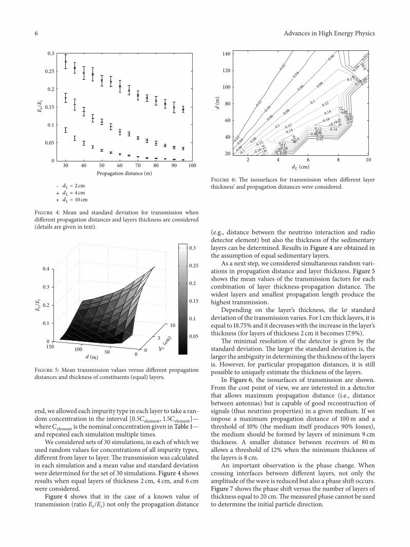
Figure 4: Mean and standard deviation for transmission whendifferent propagation distances and layers thickness are considered(details are given in text).
Et/Ei
d (m)
d L(cm
)
0.4
0.3
0.2
0.1
0150
10050 0
0
5
10
0.3
0.25
0.2
0.15
0.1
0.05
Figure 5: Mean transmission values versus different propagationdistances and thickness of constituents (equal) layers.
end, we allowed each impurity type in each layer to take a ran-dom concentration in the interval [0.5𝐶element, 1.5𝐶element]—where𝐶element is the nominal concentration given in Table 1—and repeated each simulation multiple times.
We considered sets of 30 simulations, in each of which weused random values for concentrations of all impurity types,different from layer to layer. The transmission was calculatedin each simulation and a mean value and standard deviationwere determined for the set of 30 simulations. Figure 4 showsresults when equal layers of thickness 2 cm, 4 cm, and 6 cmwere considered.
Figure 4 shows that in the case of a known value oftransmission (ratio 𝐸
𝑡/𝐸𝑖) not only the propagation distance
140
120
100
80
60
40
20
2 4 6 8 10
0.02
0.02
0.02
0.02
0.02
0.02
0.02
0.02
0.04
0.04
0.04
0.04
0.04
0.04
0.04
0.04
0.06
0.06
0.06
0.06
0.06
0.06
0.06
0.06
0.06
0.08
0.08
0.08
0.08
0.08
0.08
0.08
0.1
0.1
0.1
0.1
0.1
0.1
0.1
0.12
0.12
0.12 0.12
0.12
0.12
0.14
0.14
0.14
0.14
0.14
0.16
0.16
0.16
0.16
0.18
d(m
)
dL (cm)
Figure 6: The isosurfaces for transmission when different layerthickness’ and propagation distances were considered.
(e.g., distance between the neutrino interaction and radiodetector element) but also the thickness of the sedimentarylayers can be determined. Results in Figure 4 are obtained inthe assumption of equal sedimentary layers.
As a next step, we considered simultaneous random vari-ations in propagation distance and layer thickness. Figure 5shows the mean values of the transmission factors for eachcombination of layer thickness-propagation distance. Thewidest layers and smallest propagation length produce thehighest transmission.
Depending on the layer’s thickness, the 1𝜎 standarddeviation of the transmission varies. For 1 cm thick layers, it isequal to 18.75% and it decreases with the increase in the layer’sthickness (for layers of thickness 2 cm it becomes 17.9%).
The minimal resolution of the detector is given by thestandard deviation. The larger the standard deviation is, thelarger the ambiguity in determining the thickness of the layersis. However, for particular propagation distances, it is stillpossible to uniquely estimate the thickness of the layers.
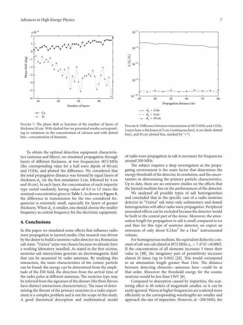
In Figure 6, the isosurfaces of transmission are shown.From the cost point of view, we are interested in a detectorthat allows maximum propagation distance (i.e., distancebetween antennas) but is capable of good reconstruction ofsignals (thus neutrino properties) in a given medium. If weimpose a maximum propagation distance of 100m and athreshold of 10% (the medium itself produces 90% losses),the medium should be formed by layers of minimum 9 cmthickness. A smaller distance between receivers of 80mallows a threshold of 12% when the minimum thickness ofthe layers is 8 cm.
An important observation is the phase change. Whencrossing interfaces between different layers, not only theamplitude of the wave is reduced but also a phase shift occurs.Figure 7 shows the phase shift versus the number of layers ofthickness equal to 20 cm.Themeasured phase cannot be usedto determine the initial particle direction.
Advances in High Energy Physics 7
2
1
0
−1
−2
−3
−4
−5
−6
Phas
e shi
ft (d
eg)
×10−6
CaTi
10 20 30 40
Number of layers
Figure 7: The phase shift as function of the number of layers ofthickness 20 cm.With dashed line we presented results correspond-ing to variations in the concentration of calcium and with dottedline—concentration of titanium.
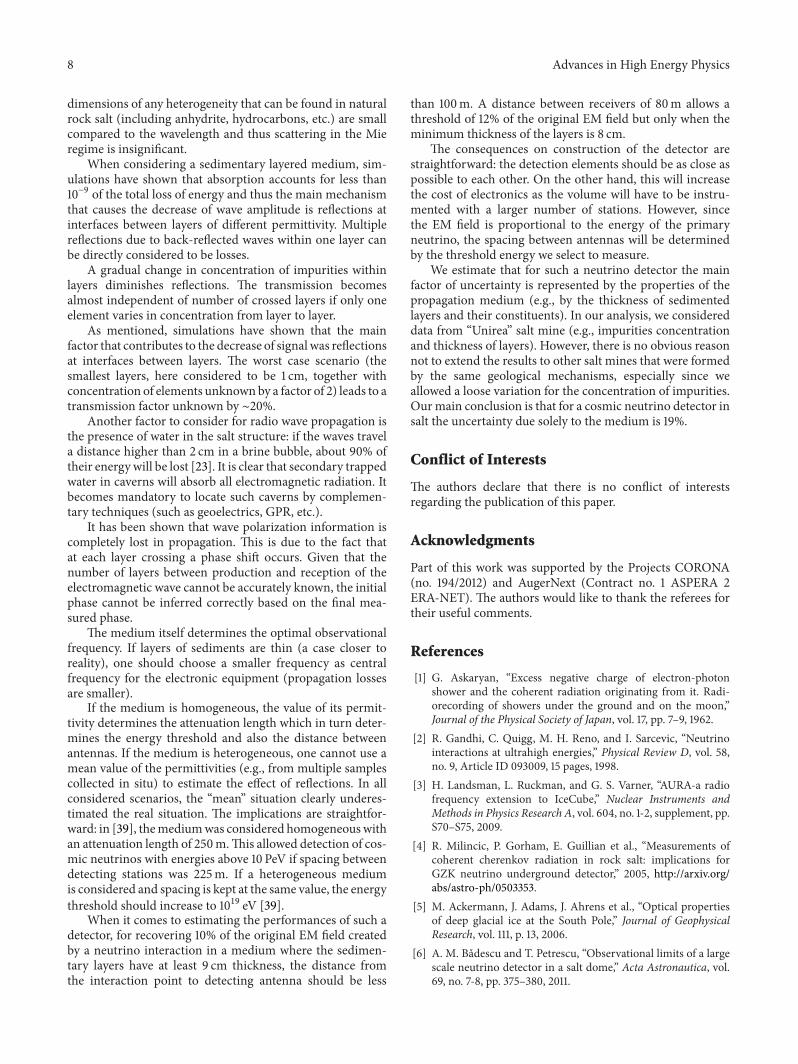
To obtain the optimal detection equipment characteris-tics (antenna and filters), we simulated propagation throughlayers of different thickness, at two frequencies: 187.5MHz(the corresponding value for a half wave dipole of 80 cm)and 1GHz, and plotted the difference. We considered thatthe total propagation distance was formed by equal layers ofthickness 𝑑
𝐿(in the first simulation 2 cm, followed by 4 cm
and 10 cm). In each layer, the concentration of each impuritytype varied randomly, having values of 0.5 to 1.5 times thenominal concentration given inTable 1. As shown in Figure 8,the difference in transmission for the two considered fre-quencies is extremely small, especially for layers of greaterthickness. When 𝑑
𝐿is smaller, one should choose the smaller
frequency as central frequency for the electronic equipment.
4. Conclusions
In this paper, we simulated some effects that influence radiowave propagation in layered media. Our research was drivenby the desire to build a neutrino radio detector in a Romaniansalt mine. “Unirea” mine was chosen because we already havea working laboratory installed. As stated in the first section,neutrino-salt interactions generate an electromagnetic fieldthat can be measured by radio antennas. By studying thisinteraction, the main characteristics of the cosmic particlecan be found: the energy can be determined from the ampli-tude of the EM field, the direction from the arrival time ofthe radio pulse at different antennas. The neutrino type maybe inferred from the signature of the shower (the three flavorshave distinct interactions characteristics). The issue of deter-mining the flavour of the primary neutrino in a radio experi-ment is a complex problem and is not the scope of this study.A good theoretical description and mathematical model
10−2
10−4
10−6
10−8
10−10
30 40 50 60 70 80
Propagation distance (m)
dL = 2 cmdL = 4 cmdL = 10 cm
Δ(E
t/Ei)
Figure 8: Difference between transmission at 187.5MHz and 1GHz.Layers have a thickness of 2 cm (continuous line), 4 cm (dash-dottedline), and 10 cm (dotted line, marked by “+”).
of radio wave propagation in salt is necessary for frequenciesaround 200MHz.
The subject requires a deep investigation as the propa-gating environment is the main factor that determines theenergy threshold of the detector, its resolution, and the uncer-tainties in determining the primary particle characteristics.Up to date, there are no extensive studies on the effects thatthe layered medium has on the performances of the detector.
We analyzed all possible types of salt heterogeneitiesand concluded that in the specific case of a radio neutrinodetector in “Unirea” salt mine only sedimentary and domalheterogeneities will affect radio wave propagation. Peripheralassociated effects can be excluded because the detector wouldbe built in the central part of the dome. Moreover, the atten-uation length for propagation in salt is small compared to iceand thus for this type of neutrino detector, we expect anextension of only about 0.2 km3 for a 1 km3 instrumentedvolume.
For homogeneousmedium, the equivalent dielectric con-stant of salt was calculated at 187.5MHz: 𝜀
𝑟= 7.4747+𝑖0.0003.
If the concentration of all elements increases 5 times theirvalue in [38], the imaginary part of permittivity increasesalmost 10 times (up to 0.002) [23]. This would correspondto an attenuation length greater than 1 km. The distancebetween detecting elements—antennas here—could be atthat order. Moreover the threshold energy for the cosmicneutrino would be less than 1 PeV [6].
Compared to absorption caused by impurities, the scat-tering effect is 40 orders of magnitude smaller, so it can beeasily ignored.Waves at higher frequencies are scatteredmoreefficiently as the corresponding wavelengths are smaller andapproach the size of impurities. However, at ∼200MHz, the
8 Advances in High Energy Physics
dimensions of any heterogeneity that can be found in naturalrock salt (including anhydrite, hydrocarbons, etc.) are smallcompared to the wavelength and thus scattering in the Mieregime is insignificant.
When considering a sedimentary layered medium, sim-ulations have shown that absorption accounts for less than10−9 of the total loss of energy and thus the main mechanismthat causes the decrease of wave amplitude is reflections atinterfaces between layers of different permittivity. Multiplereflections due to back-reflected waves within one layer canbe directly considered to be losses.
A gradual change in concentration of impurities withinlayers diminishes reflections. The transmission becomesalmost independent of number of crossed layers if only oneelement varies in concentration from layer to layer.
As mentioned, simulations have shown that the mainfactor that contributes to the decrease of signal was reflectionsat interfaces between layers. The worst case scenario (thesmallest layers, here considered to be 1 cm, together withconcentration of elements unknownby a factor of 2) leads to atransmission factor unknown by ∼20%.
Another factor to consider for radio wave propagation isthe presence of water in the salt structure: if the waves travela distance higher than 2 cm in a brine bubble, about 90% oftheir energy will be lost [23]. It is clear that secondary trappedwater in caverns will absorb all electromagnetic radiation. Itbecomes mandatory to locate such caverns by complemen-tary techniques (such as geoelectrics, GPR, etc.).
It has been shown that wave polarization information iscompletely lost in propagation. This is due to the fact thatat each layer crossing a phase shift occurs. Given that thenumber of layers between production and reception of theelectromagnetic wave cannot be accurately known, the initialphase cannot be inferred correctly based on the final mea-sured phase.
The medium itself determines the optimal observationalfrequency. If layers of sediments are thin (a case closer toreality), one should choose a smaller frequency as centralfrequency for the electronic equipment (propagation lossesare smaller).
If the medium is homogeneous, the value of its permit-tivity determines the attenuation length which in turn deter-mines the energy threshold and also the distance betweenantennas. If the medium is heterogeneous, one cannot use amean value of the permittivities (e.g., from multiple samplescollected in situ) to estimate the effect of reflections. In allconsidered scenarios, the “mean” situation clearly underes-timated the real situation. The implications are straightfor-ward: in [39], themediumwas considered homogeneouswithan attenuation length of 250m.This allowed detection of cos-mic neutrinos with energies above 10 PeV if spacing betweendetecting stations was 225m. If a heterogeneous mediumis considered and spacing is kept at the same value, the energythreshold should increase to 1019 eV [39].
When it comes to estimating the performances of such adetector, for recovering 10% of the original EM field createdby a neutrino interaction in a medium where the sedimen-tary layers have at least 9 cm thickness, the distance fromthe interaction point to detecting antenna should be less
than 100m. A distance between receivers of 80m allows athreshold of 12% of the original EM field but only when theminimum thickness of the layers is 8 cm.
The consequences on construction of the detector arestraightforward: the detection elements should be as close aspossible to each other. On the other hand, this will increasethe cost of electronics as the volume will have to be instru-mented with a larger number of stations. However, sincethe EM field is proportional to the energy of the primaryneutrino, the spacing between antennas will be determinedby the threshold energy we select to measure.
We estimate that for such a neutrino detector the mainfactor of uncertainty is represented by the properties of thepropagation medium (e.g., by the thickness of sedimentedlayers and their constituents). In our analysis, we considereddata from “Unirea” salt mine (e.g., impurities concentrationand thickness of layers). However, there is no obvious reasonnot to extend the results to other salt mines that were formedby the same geological mechanisms, especially since weallowed a loose variation for the concentration of impurities.Ourmain conclusion is that for a cosmic neutrino detector insalt the uncertainty due solely to the medium is 19%.
Conflict of Interests
The authors declare that there is no conflict of interestsregarding the publication of this paper.
Acknowledgments
Part of this work was supported by the Projects CORONA(no. 194/2012) and AugerNext (Contract no. 1 ASPERA 2ERA-NET). The authors would like to thank the referees fortheir useful comments.
References
[1] G. Askaryan, “Excess negative charge of electron-photonshower and the coherent radiation originating from it. Radi-orecording of showers under the ground and on the moon,”Journal of the Physical Society of Japan, vol. 17, pp. 7–9, 1962.
[2] R. Gandhi, C. Quigg, M. H. Reno, and I. Sarcevic, “Neutrinointeractions at ultrahigh energies,” Physical Review D, vol. 58,no. 9, Article ID 093009, 15 pages, 1998.
[3] H. Landsman, L. Ruckman, and G. S. Varner, “AURA-a radiofrequency extension to IceCube,” Nuclear Instruments andMethods in Physics Research A, vol. 604, no. 1-2, supplement, pp.S70–S75, 2009.
[4] R. Milincic, P. Gorham, E. Guillian et al., “Measurements ofcoherent cherenkov radiation in rock salt: implications forGZK neutrino underground detector,” 2005, http://arxiv.org/abs/astro-ph/0503353.
[5] M. Ackermann, J. Adams, J. Ahrens et al., “Optical propertiesof deep glacial ice at the South Pole,” Journal of GeophysicalResearch, vol. 111, p. 13, 2006.
[6] A. M. Badescu and T. Petrescu, “Observational limits of a largescale neutrino detector in a salt dome,” Acta Astronautica, vol.69, no. 7-8, pp. 375–380, 2011.

Advances in High Energy Physics 9
[7] A. M. Badescu, T. Petrescu, O. Fratu et al., “Propagation effectson radio signals emitted in salt by neutrino-induced elec-tromagnetic showers,” in Proceedings of the 21st InternationalConference Radioelektronika, pp. 1–4, Brno, Czech Republic,April 2011.
[8] B. Hapke, Theory of Reflectance and Emittance Spectroscopy,Cambridge University Press, Cambridge, UK, 1993.
[9] J. Alvarez-Muniz, R. A. Vazquez, and E. Zas, “Calculationmethods for radio pulses from high energy showers,” PhysicalReview D, vol. 62, no. 6, Article ID 063001, 9 pages, 2000.
[10] J. Alvarez-Muniz, E. Marques, R. A. Vazquez, and E. Zas,“Coherent radio pulses from showers in different media: aunified parameterization,” Physical Review D, vol. 74, no. 7,2006.
[11] M. Jeremic, Rock Mechanics in Salt Mining, Taylor and Francis,New York, NY, USA, 1994.
[12] V. Gundelach and D. Eisenburger, “Principle of a directionsensitive borehole antenna with advanced technology and dataexamples,” in Proceedings of the 4th International Workshop onAdvanced Ground Penetrating Radar (IWAGPR ’07), pp. 28–31,June 2007.
[13] W. Al-Nuaimy, Y. Huang, M. Nakhkash, M. T. C. Fang, V. T.Nguyen, andA. Eriksen, “Automatic detection of buried utilitiesand solid objects with GPR using neural networks and patternrecognition,” Journal of Applied Geophysics, vol. 43, no. 2–4, pp.157–165, 2000.
[14] D. L. Moffatt and R. J. Puskar, “A subsurface electromagneticpulse radar,” Geophysics, vol. 41, no. 3, pp. 506–518, 1976.
[15] L. Peters Jr. and J. D. Young, “Applications of subsurfacetransient radars,” inTime-DomainMeasurements in Electromag-netics, E. K. Miller, Ed., Van Nostrand Reinhold, London, UK,1986.
[16] O.Missaoui,H. Frigui, andP.Gader, “Land-mine detectionwithground-penetrating radar using multistream discrete hiddenMarkov models,” IEEE Transactions on Geoscience and RemoteSensing, vol. 49, no. 6, pp. 2080–2099, 2011.
[17] Z. Zyada, T. Matsuno, Y. Hasegawa, S. Sato, and T. Fukuda,“Advances in GPR-based landmine automatic detection,” Jour-nal of the Franklin Institute, vol. 348, no. 1, pp. 66–78, 2011.
[18] M. E. Bechtel and A. V. Alongi, “Antennas and pulses fora vehicular-mounted mine detector,” Report MA-5366-E-1,Calspan Corporation, Buffalo, NY, USA, 1974.
[19] G. S. Smith and W. R. Scott, “A scale model for studyingground penetrating radars,” IEEE Transactions on Geoscienceand Remote Sensing, vol. 27, no. 4, pp. 358–363, 1989.
[20] D. A. Hill, “Fields of horizontal currents located above theearth,” IEEE Transactions on Geoscience and Remote Sensing,vol. 26, no. 6, pp. 726–732, 1988.
[21] A. M. Badescu, V. Savu, and O. Fratu, “Preliminary testsin Unirea salt mine (Slanic Prahova, Romania),” Report 4,University Politehnica of Bucharest, Bucharest, Romania, 2011.
[22] M. Stefanescu, O. Dicea, and G. Tari, “Influence of extensionand compression on salt diapirism in its type area, EastCarpathians Bend area, Romania,” Geological Society SpecialPublication, vol. 174, pp. 131–147, 2000.
[23] A. M. Badescu, “Considerations on an underground neutrinoradio detector in salt,” Journal of Instrumentation, 2013.
[24] L. D. Landau and E.M. Lifschitz, Electrodynamics of ContinuousMedia, Tehnica, Bucharest, Romania, 1968.
[25] G. E. Archie, “Electrical resistivity as an aid in core analysisinterpretation,” Transaction of the American Institute of MiningEngineers, vol. 146, pp. 4–2, 1942.
[26] U. Yaramanci, “Geoelectric exploration and monitoring in rocksalt for the safety assessment of underground waste disposalsites,” Journal of Applied Geophysics, vol. 44, no. 2-3, pp. 181–196,2000.
[27] R. Somaraju and J. Trumpf, “Frequency, temperature and salin-ity variation of the permittivity of seawater,” IEEE Transactionson Antennas and Propagation, vol. 54, no. 11, pp. 3441–3448,2006.
[28] T. Meissner and F. J. Wentz, “The complex dielectric constantof pure and sea water from microwave satellite observations,”IEEE Transactions on Geoscience and Remote Sensing, vol. 42,no. 9, pp. 1836–1849, 2004.
[29] M. Sato and R. Thierbach, “Analysis of a borehole radar incross-hole mode,” IEEE Transactions on Geoscience and RemoteSensing, vol. 29, no. 6, pp. 899–904, 1991.
[30] M. Zhdanov, “Generalized effective-medium theory of inducedpolarization,” Geophysics, vol. 73, no. 5, pp. F197–F211, 2008.
[31] M. D. O’Connell, “A heuristic method of removing micropulsa-tions from airborne magnetic data,” The Society of ExplorationGeophysicists, vol. 20, no. 11, pp. 1242–1246, 2001.
[32] J. Melvin, Evaporites Petroleum and Mineral Resources, Elsevier,London, UK, 1991.
[33] A. S. Alsharhan and M. G. Salah, “Tectonic implications ofdiapirism on hydrocarbon accumulation in the United ArabEmirates,” Bulletin of Canadian Petroleum Geology, vol. 45, no.3, pp. 279–296, 1997.
[34] N. Black and M. S. Zhdanov, “Active geophysical monitoring ofhydrocarbon reservoirs using EMmethods,” in Active Geophys-ical Monitoring, J. Kasahara, V. Korneev, and M. S. Zhdanov,Eds., pp. 135–159, Elsevier, London, UK, 2010.
[35] P. Gorham, D. Saltzberg, A. Odian et al., “Measurements of thesuitability of large rock salt formations for radio detection ofhigh-energy neutrinos,” Nuclear Instruments and Methods inPhysics Research A, vol. 490, no. 3, pp. 476–491, 2002.
[36] M. Chiba, T. Kamijo, O. Yasuda et al., “Salt neutrino detectorfor ultrahigh-energy neutrinos,” Physics of Atomic Nuclei, vol.67, no. 11, pp. 2050–2053, 2004.
[37] A. Connolly, A. Goodhue, C. Miki, R. Nichol, and D. Saltzberg,“Measurements of radio propagation in rock salt for thedetection of high-energy neutrinos,” Nuclear Instruments andMethods in Physics Research A, vol. 599, no. 2-3, pp. 184–191,2009.
[38] C. Cristache, C. A. Simion, R.M.Margineanu et al., “Epithermalneutrons activation analysis, radiochemical and radiometricinvestigations of evaporitic deposits of Slanic-Prahova (Roma-nia) salt mine,” Radiochimica Acta, vol. 97, no. 6, pp. 333–337,2009.
[39] P. W. Gorham, D. Saltzberg, R. C. Field et al., “Accelerator mea-surements of the Askaryan effect in rock salt: a roadmap towardteraton underground neutrino detectors,” Physical Review D,vol. 72, no. 2, Article ID 023002, pp. 1–22, 2005.

Submit your manuscripts athttp://www.hindawi.com
Hindawi Publishing Corporationhttp://www.hindawi.com Volume 2014
High Energy PhysicsAdvances in
The Scientific World JournalHindawi Publishing Corporation http://www.hindawi.com Volume 2014
Hindawi Publishing Corporationhttp://www.hindawi.com Volume 2014
FluidsJournal of
Atomic and Molecular Physics
Journal of
Hindawi Publishing Corporationhttp://www.hindawi.com Volume 2014
Hindawi Publishing Corporationhttp://www.hindawi.com Volume 2014
Advances in Condensed Matter Physics
OpticsInternational Journal of
Hindawi Publishing Corporationhttp://www.hindawi.com Volume 2014
Hindawi Publishing Corporationhttp://www.hindawi.com Volume 2014
AstronomyAdvances in
International Journal of
Hindawi Publishing Corporationhttp://www.hindawi.com Volume 2014
Superconductivity
Hindawi Publishing Corporationhttp://www.hindawi.com Volume 2014
Statistical MechanicsInternational Journal of
Hindawi Publishing Corporationhttp://www.hindawi.com Volume 2014
GravityJournal of
Hindawi Publishing Corporationhttp://www.hindawi.com Volume 2014
AstrophysicsJournal of
Hindawi Publishing Corporationhttp://www.hindawi.com Volume 2014
Physics Research International
Hindawi Publishing Corporationhttp://www.hindawi.com Volume 2014
Solid State PhysicsJournal of
Computational Methods in Physics
Journal of
Hindawi Publishing Corporationhttp://www.hindawi.com Volume 2014
Hindawi Publishing Corporationhttp://www.hindawi.com Volume 2014
Soft MatterJournal of
Hindawi Publishing Corporationhttp://www.hindawi.com
AerodynamicsJournal of
Volume 2014
Hindawi Publishing Corporationhttp://www.hindawi.com Volume 2014
PhotonicsJournal of
Hindawi Publishing Corporationhttp://www.hindawi.com Volume 2014
Journal of
Biophysics
Hindawi Publishing Corporationhttp://www.hindawi.com Volume 2014
ThermodynamicsJournal of