requirements for the polish digital terrestrial television receiver...
TRANSCRIPT

REQUIREMENTS FOR THE POLISH
DIGITAL TERRESTRIAL TELEVISION
RECEIVER
Profiles 0, 1 and 2
Version 0.6
Prepared by:
Problem Group for Technology & Equipment of the Interdepartmental Team for Digital Broadcasting
Coordinated by:
Digital Broadcasting Section of the Polish Chamber for Commerce for Electronics and Telecommunications
Warszawa, June 2009
® ®


Requirements for the Polish DTT Receiver v. 0.6 1/54
CONTENTS
INTRODUCTION ................................................................................................................... 5
1. SCOPE ............................................................................................................................ 6
2. DOCUMENT HISTORY ....................................................................................................... 6
3. NORMATIVE REFERENCES ................................................................................................ 6
4. DEFINITIONS .................................................................................................................... 9
5. ABBREVIATIONS AND ACRONYMS.................................................................................... 10
6. GENERAL CHARACTERISTIC OF THE DIGITAL RECEIVER ................................................... 13
6.1. Introduction ........................................................................................................ 13
6.2. Receiving Capabilities ....................................................................................... 14
6.3. Scanning Procedure........................................................................................... 14
6.4. Access to Services............................................................................................. 14
6.5. SI Navigator ........................................................................................................ 14
6.6. Auto Installation ................................................................................................. 14
6.7. Conditional Access (option) .............................................................................. 14
6.8. Parental Access Control .................................................................................... 14
6.9. Video Decoder .................................................................................................... 14
6.10. Audio decoder .................................................................................................... 14
6.11. Teletext and DVB Subtitles ................................................................................ 15
6.12. API ....................................................................................................................... 15
6.13. Return Channel................................................................................................... 15
6.14. System Software Update.................................................................................... 15
6.15. Power Supply Requirements ............................................................................. 15
7. RF TUNER AND DEMODULATOR OF THE DIGITAL RECEIVER ............................................. 15
7.1. Scanning Procedure........................................................................................... 15
7.2. Quality Reception Detector................................................................................ 16
7.3. Parameters of RF Tuner and Demodulator....................................................... 16
8. MPEG-2 DEMULTIPLEXER ............................................................................................. 20
8.1. General Requirements ....................................................................................... 20
8.2. Constraints and Extensions .............................................................................. 20
8.3. DVB Descrambler Performance......................................................................... 21
8.4. System Clock Recovery..................................................................................... 21
9. VIDEO DECODER ........................................................................................................... 21
9.1. Basic Requirements........................................................................................... 21
9.2. Constraints and Extensions .............................................................................. 21
10. AUDIO DECODER ........................................................................................................... 24
10.1. Basic Requirements........................................................................................... 24
10.2. Scope of Requirements ..................................................................................... 24
10.3. Constraints and Extensions .............................................................................. 24
11. TELETEXT AND DVB SUBTITLES ..................................................................................... 27

2/54 Requirements for the Polish DTT Receiver v. 0.6
11.1. Teletext................................................................................................................27
11.2. DVB Subtitles......................................................................................................27
12. GRAPHICS PROCESSOR .................................................................................................27
12.1. Profile 0 ...............................................................................................................27
12.2. Profile 1 and 2.....................................................................................................28
13. INTERFACES AND SIGNAL LEVELS OF THE RECEIVER .......................................................28
13.1. Introduction ........................................................................................................28
13.2. Analogue TV Reception (option) .......................................................................28
13.3. Digital Interfaces.................................................................................................29
13.4. Analogue Interfaces ...........................................................................................31
13.5. Remote Control Interface...................................................................................32
13.6. Cordless Keyboard Interface (option)...............................................................32
14. INTERFACES FOR CONDITIONAL ACCESS.........................................................................32
14.1. General Remarks................................................................................................32
14.2. Minimum Requirements .....................................................................................32
14.3. Use of the DVB-CI...............................................................................................32
14.4. Use of Smart-Card Reader .................................................................................33
15. ELECTRICAL PERFORMANCE ..........................................................................................34
15.1. Introduction ........................................................................................................34
15.2. Video Performance of RGB and PAL Signals...................................................34
15.3. Audio Performance of Decoded Digital Signal .................................................35
16. SYSTEM SOFTWARE UPDATE..........................................................................................36
16.1. Introduction ........................................................................................................36
16.2. Minimum Requirements .....................................................................................36
17. SERVICE INFORMATION ..................................................................................................36
18. NAVIGATOR ...................................................................................................................37
18.1. General Requirements .......................................................................................37
18.2. Service List .........................................................................................................37
18.3. Event Schedule Guide (ESG) .............................................................................39
19. SYSTEM SOFTWARE AND API .........................................................................................40
19.1. Profile 0 ...............................................................................................................40
19.2. Profile 1 ...............................................................................................................40
19.3. Profile 2 ...............................................................................................................40
20. USER PREFERENCES .....................................................................................................40
20.1. Stored Preferences.............................................................................................40
20.2. Deletion of Service List ......................................................................................40
20.3. Reset to Factory Settings ..................................................................................40
21. REQUIREMENTS OF POWER SUPPLY OF DIGITAL RECEIVER..............................................41
22. SAFETY REQUIREMENTS OF DIGITAL RECEIVER...............................................................41
23. ELECTROMAGNETIC COMPATIBILITY OF DIGITAL RECEIVER..............................................41
23.1. Common Requirements .....................................................................................41
23.2. Profile 0 and 1 without data interface ...............................................................41

Requirements for the Polish DTT Receiver v. 0.6 3/54
23.3. Profile 0 and 1 with data interface or Profile 2 ................................................. 41
ANNEX A.............................................................................................................................. 43
1. LIST OF DVB-T CHANNELS IN BAND III OF VHF RANGE ................................................... 43
2. LIST OF DVB-T CHANNELS IN BAND IV AND V OF UHF RANGE......................................... 43
ANNEX B.............................................................................................................................. 45
1. REMOTE CONTROL UNIT (RCU) ..................................................................................... 45
1.1. General Remarks................................................................................................ 45
1.2. Functions ............................................................................................................ 45
1.3. Design and finishing .......................................................................................... 48
2. CORDLESS KEYBOARD .................................................................................................. 48
ANNEX C.............................................................................................................................. 49
1. COMPARISON OF PROFILES OF DIGITAL RECEIVERS FOR POLAND .................................... 49
1.1. Introduction ........................................................................................................ 49
1.2. Description of Columns of Table 19.................................................................. 49

4/54 Requirements for the Polish DTT Receiver v. 0.6
LIST OF TABLES
Table 1. Delta values between picture failure point and reference BER .......................17
Table 2. C/N for reference BER (dB) ................................................................................18
Table 3. Long echo test profile ........................................................................................20
Table 4. Short echo test profile........................................................................................20
Table 5. Audio formats presentation on digital outputs.................................................25
Table 6. Electrical performance of TV modulator ...........................................................29
Table 7. SCART interfaces requirements ........................................................................31
Table 8. Video performance of digital receiver ...............................................................35
Table 9. Audio performance of digital receiver...............................................................35
Table 10. NIT descriptors .................................................................................................38
Table 11. SDT descriptors ................................................................................................38
Table 12. EIT p/f descriptors ............................................................................................39
Table 13. EIT schedule descriptors .................................................................................39
Table 14. TOT descriptor ..................................................................................................40
Table 15. List of DVB-T channels in Band III of VHF range............................................43
Table 16. List of DVB-T channels in Band IV of UHF range ...........................................43
Table 17. List of DVB-T channels in Band V of UHF range ............................................44
Table 18. Sequence of characters assigned to numeric pad.........................................46
Table 19. Comparison of requirements of digital receiver .............................................49

Requirements for the Polish DTT Receiver v. 0.6 5/54
INTRODUCTION
Television has evolved over the last half century from an up-market entertainment medium to becoming the major information tool around the world. At present television is available to virtually all people around the globe, be it individually or in a community setting and the num-ber of used TV-sets has already long ago exceeded the number of fixed phones.
The advent of the personal computer enabling via Internet instant access to the huge amount of information caused that broadcasters to survive on the market began to seek new means of improvement of their offer and delivering it to consumers with best transport channels.
Digitalisation, taken from the world of information technology was the obvious choice. First distribution channel subjected to this process was satellite broadcasting. At present in the most of European countries a digital terrestrial television broadcasting is introduced on the basis of governmental strategies taking into account the role of this mass-media in building of information society. It is necessary to expect that CATV networks, distributing signals re-ceived from satellite and terrestrial, also will switch to digital in the nearest time.
Success of the Polish Government strategy to switch to digital transmission depends mainly on the society conviction that new offer will be attractive and affordable as well as the access will not be too complicated and will not be connected with considerable additional costs. It can be assured by setting out one transmission standard and the minimum set of technical parameters for a DTT receiver, giving the stable and safe foundation for development of new services and applications as well as for launching mass-production of receivers what, thanks to the effect of an economy of scale, should bring the significant cost reduction.
The effect of mass-production scale of receivers is additionally strengthen if the unification of parameters encompasses more than one country. For example, Scandinavian countries made so adopting common requirements for the transmission system and minimum set of parameters of the digital receiver.
Due to limited accessibility to the spectrum for terrestrial digital television in the period of the indispensable coexistence of analogue and digital transmissions (simulcasting) it was adopted in Poland that already from the launch of DTT transmissions the most effective compression technology available for video and audio signals should be adopted.
Moreover, in view of more and more deployment of TV-sets ready to display of HD pictures, the digital receivers should be ready to receive and decode terrestrial HD transmissions to make possible switchover to the terrestrial high resolution digital television (HDTV) as quickly as possible without necessity to keep the parallel transmission of the same programs in stan-dard resolution (SDTV).
Above goals laid down at foundations of assumptions on which this document is based. The draft has been developed in the Digital Broadcasting Section of the KIGEiT. The EN 62216 [39] and the NorDig Unified Requirements [57] were mainly used as a reference.

6/54 Requirements for the Polish DTT Receiver v. 0.6
1. SCOPE Present document sets out the technical and exploitation requirements whose fulfilment is indispensable for the correct reception of signals delivered by means of the terrestrial broad-casting using the DVB-T system and MPEG-2 transport stream to deliver audio-visual con-tent and another services. As essential requirements we adopted parameters of the digital television receiver defined in ETSI TS 101 154 [14] as „25 Hz H.264/AVC HDTV video, MPEG-2 Layer 2 and E-AC-3 audio, for a Baseline IRD able to decode up to 1920 x 1080 interlaced 25 Hz video pictures or 1280 x 720 progressive 50 Hz video pictures”.
The requirements refer to the integrated digital receiver with decoder (IRD) available as in-dependent device (STB) or composing a relevant part of the integrated TV-set (iDTV), both supplied from the power network of the alternating current. Receivers supplied from battery or through any computer interface are not covered by this specification.
The document was divided on following parts:
• general characteristics – describes basic features from the user point of view;
• specification of the electric part – includes detailed description of electric parameters of the receiver;
• software specification – includes detailed description of requirements and recom-mendations for each elements constituting the software of the receiver.
When a given feature is mandatory, the word “shall” is used and if it is not mandatory the word „should” or “option” is used.
The necessity of meeting requirements of this specification does not preclude expendability of the receiver for other features improving its functionality or usefulness.
2. DOCUMENT HISTORY
Date Version Changes
April 2005 0.1 First draft for thr Group for technology and equipment of the Interde-partmental Team for Digital Broadcasting
December 2008 0.4 Draft limited to the DTT only
January 2009 0.5 Draft to be agreed within the STiRC KIGEiT
June 2009 0.6 Draft agreed by the Group for technology and equipment of the Inter-departmental Team
3. NORMATIVE REFERENCES The following documents contain provisions which, through reference in this text, constitute provisions of the present document.
• References are either specific (identified by date of publication and/or edition num-ber or version number) or non-specific.
• For a specific reference, subsequent revisions do not apply.
• For a non-specific reference, the latest version applies.
[1] DVB A011 Common Scrambling Algorithm. DVB Blue Book A011
[2] EG 202 116 V1.2.1 Human Factors (HF); Guidelines for ICT products and services; "Design for All". ETSI
[3] EN 300 468 V1.9.1 Digital Video Broadcasting (DVB); Specification for Service Infor-mation (SI) in DVB systems. ETSI

Requirements for the Polish DTT Receiver v. 0.6 7/54
[4] EN 300 472 V1.3.1 Digital Video Broadcasting (DVB); Specification for Conveying ITU-R System B Teletext in DVB Bitstreams. ETSI
[5] EN 300 706 V1.2.1 Enhanced Teletext specification. ETSI
[6] EN 300 743 V1.3.1 Digital Video Broadcasting (DVB); DVB Subtitling Systems. ETSI
[7] EN 300 744 V1.6.1 Digital Video Broadcasting (DVB); Framing structure, channel co-ding and modulation for digital terrestrial television. ETSI
[8] ES 201 381 V1.1.1 Human Factors (HF); Telecommunications keypads and keyboards; Tactile identifiers. ETSI
[9] ES 202 130 V2.1.2 Human Factors (HF); User Interfaces; Character repertoires, order-ings and assignments to the 12-key telephone keypad (for European languages and other languages used in Europe). ETSI
[10] ETR 162 Digital Broadcasting Systems for Television, Sound and Data Services; Allo-cation of Service Information (SI) Codes for Digital Video Broadcasting (DVB) Systems. ETSI
[11] ETR 289 Digital Video Broadcasting (DVB); Support for use of scrambling and Condi-tional Access within digital broadcasting systems. ETSI
[12] ETS 300 640 Human Factors (HF); Assignment of alphabetic letters to digits on stan-dard telephone keypad arrays. ETSI
[13] TR 101 211 V1.8.1 Digital Broadcasting Systems for Television, Sound and Data Ser-vices; Guidelines on the Implementation and Usage of DVB Service Information. ETSI
[14] TS 101 154 V1.8.1 Digital Video Broadcasting (DVB); Implementation guidelines for the use Video and Audio Coding in Broadcasting Applications based on the MPEG-2 Transport Stream. ETSI
[15] TS 101 699 V1.1.1 Digital Video Broadcasting (DVB); Extensions to the Common Inter-face Specification. ETSI
[16] TS 102 006 V1.3.2 Digital Video Broadcasting (DVB); Specification for System Soft-ware Update in DVB systems. ETSI
[17] TS 102 201 V1.2.1 Digital Video Broadcasting (DVB); Interfaces for DVB Integrated Receiver Decoder (DVB-IRD). ETSI
[18] TS 102 366 V1.2.1 Digital Video Broadcasting (DVB); Digital Audio Compression (AC-3, Enhanced AC-3) Standard. ETSI
[19] TS 102 590 V.1.1.1 Digital Video Broadcasting (DVB); Multimedia Home Platform (MHP) Specification 1.2. ETSI
[20] ISO 639-2:1998 Codes for the representation of names of languages – Part 2: Alpha-3 code
[21] ISO/IEC 7816, 1-3 Identification cards – Integrated circuit cards with contacts, Parts 1-3
[22] ISO/IEC 8859-2:1999 Information technology – 8-bit single-byte coded graphic charac-ter sets – Part 2: Latin alphabet No. 2
[23] ISO/IEC 13818-1 Information Technology – Generic Coding of Moving Pictures and Associated Audio Information. Part 1: Systems
[24] ISO/IEC 13818-3:1998 Information technology – Generic coding of moving picture and associated audio information; Part 3: Audio
[25] EN 50049-1:1997 + A1:1998 Domestic electronic equipment interconnection require-ments: Peritelevision Connector. CENELEC

8/54 Requirements for the Polish DTT Receiver v. 0.6
[26] EN 50083-7:1996 + A1:2000 Cable networks for television signals, sound signals and interactive services – Part 7: System performance. CENELEC
[27] EN 50157-2-1:1998 Domestic and similar equipment interconnection requirements: AV link-Part 2-1: Signal quality matching and automatic selection of source devices. CENELEC
[28] EN 50160:2007 Voltage characteristics of electricity supplied by public distribution sys-tems. CENELEC
[29] EN 50221:1997 Common Interface for Conditional Access and other DVB Decoder Ap-plications. CENELEC
[30] EN 55013:1997 + A1:2003 + A2:2006 Sound and television broadcast receivers and associated equipment – Radio disturbance characteristics – Limits and methods of measurement. CENELEC
[31] EN 55020:2007 Sound and television broadcast receivers and associated equipment - Immunity characteristics - Limits and methods of measurement. CENELEC
[32] EN 55022:2006 + A1:2007 Information technology equipment – Radio disturbance characteristics – Limits and methods of measurement. CENELEC
[33] EN 55024:1998 + A1:2001 + A2:2003 + IS1:2007 Information technology equipment – Immunity characteristics – Limits and methods of measurement. CENELEC
[34] EN 60065:2002 + A1:2006 + A11:2008 Audio, video and similar electronic apparatus – Safety requirements. CENELEC
[35] EN 60958 Digital audio interface. (Part 1 General, Part 3 Consumer). CENELEC
[36] EN 61000-6-1:2007 Electromagnetic compatibility (EMC) – Part 6-1: Generic standards – Immunity for residential, commercial and light-industrial environments. CENELEC
[37] EN 61000-6-3:2007 Electromagnetic Compatibility (EMC) – Part 6-3: Generic stan-dards – Emission standard for residential, commercial and light-industrial environ-ments. CENELEC
[38] EN 61937:2007 Digital audio - Interface for non-linear PCM audio bitstreams applying IEC 60958 – (Part 1: General. Part 3. Nonlinear PCM bitstreams according to AC-3 and enhanced AC-3 formats) CENELEC
[39] EN 62216:2009 Digital terrestrial television receivers for the DVB-T system. CENELEC
[40] IEC 60038:2002 IEC standard voltages
[41] IEC 60169-2:1965 + A1:1982 Radio-frequency connectors, Part 2: Coaxial unmatched connectors
[42] IEC 60603-14:1998 Connectors for frequencies below 3 MHz for use with printed boards – Part 14: Detail specification for circular connectors for low frequency audio and video applications such as audio, video and audio-visual equipment
[43] ITU-R Recommendation BS.468 Measurement of audio-frequency noise voltage level in sound broadcasting
[44] ITU-R Recommendation BT.1700 Characteristics of composite video signals for con-ventional analogue television systems
[45] ITU-R Recommendation BT.1701 Characteristics of radiated signals for conventional analogue television systems
[46] ITU-T Recommendation E.161:2001 Arrangement of digits, letters and symbols on tele-phones and other devices that can be used for gaining access to a telephone network

Requirements for the Polish DTT Receiver v. 0.6 9/54
[47] ITU-T Recommendation H.264:2007 Advanced video coding for generic audiovisual services
[48] ITU-T Recommendation J.61:1990 + A1:2007 Transmission performance of television circuits designed for use in international connections
[49] ITU-T Recommendation V.90:1998 A digital modem and analogue modem pair for use on the Public Switched Telephone Network (PSTN) at data signalling rates of up to 56 000 bit/s downstream and up to 33 600 bit/s upstream
[50] IEEE 802.3 IEEE Standard for Information Technology –Telecommunications and in-formation exchange between systems – Local and metropolitan area networks –Specific requirements Part 3: Carrier Sense Multiple Access with Collision Detection (CSMA/CD) Access Method and Physical Layer Specifications
[51] IEEE 802.11 IEEE Standard for Information Technology – Telecommunications and information exchange between systems – Local and metropolitan area network-Specific requirements Part 11: Wireless LAN Medium Access Control (MAC) and Physical Layer (PHY) Specifications
[52] IEEE 1394:2008 Standard for a high performance serial bus
[53] Bluetooth 2.0 Specification of the Bluetooth System, 4 November 2004. Bluetooth SIG
[54] CEA-770.3 Consumer Electronics Association (CEA): Standard Definition TV Analogue Component Video Interface, CEA -770.2C, November 2001. www.ce.org/Standards
[55] “High-Definition Multimedia Interface”, ver. 1.3a, November 10, 2006. HDMI Licensing, LLC. www.hdmi.org/download/HDMISpecification13a.pdf
[56] “High-Bandwidth Digital Content Protection System”, rev. 1.3, December 21, 2006. Digital Content Protection LLC. www.digital-cp.com
[57] NorDig Unified Requirements for Integrated Receiver-Decoder for use in cable, satel-lite, terrestrial and IP-based networks, ver. 2.0, July 2008
[58] Universal Serial Bus Port Specification, Revision 2.0, April 27, 2000
[59] R206-001:1998 Guidelines for Implementation and Use of the Common Interface for DVB Decoder Applications. CENELEC
[60] Code of Conduct on Energy Efficiency of Digital TV Service Systems. Version 7. Ispra, 15 January 2008. European Commission, Directorate-General JRC. http://re.jrc.ec.europa.eu/energyefficiency/pdf/CoC%20Digital%20TV-version%207.pdf
[61] Dolby Technical Bulletin 11: Requirement Updates For Dolby Digital and Dolby Digital Plus in DVB Products. 2007 Dolby Labs Inc.
[62] Regulation of the Minister of Infrastructure of … 2009 on technical and exploitation re-quirements for consumer equipment used for reception of digital terrestrial television transmissions. O. J. No.
4. DEFINITIONS Terms used in this document mean:
4.1. Bootloader – built-in loading software enabling remote update of the system software after switch-on of the receiver.
4.2. Bouquet – collection of Radio and/or TV services marketed as a single entity.
4.3. Digital platform – bouquet of programs and digital services offered usually by one pro-vider. It is recommended so that all terrestrial multiplexes in Poland constitute one digi-tal platform.

10/54 Requirements for the Polish DTT Receiver v. 0.6
4.4. Digital receiver – a consumer equipment used for the reception of digital terrestrial television signals consisting of at least RF-tuner, demodulator, demultiplexer and de-coders of received services, with display (iDTV) or without display (STB).
4.5. Event – grouping of elementary broadcast data streams with a defined start and end time belonging to a common service.
4.6. Interactive receiver – digital receiver allowing to use interactive TV services locally or via return channel.
4.7. Interactive television (iTV) – applications allowing the user to access additional content and services, connected or not with broadcasted programme, by means of the interac-tion performed by the user interface with the receiver or by means of any return chan-nel.
4.8. Letterbox – manner of display of a panoramic picture (usually in aspect ratio 16:9) while preserving original aspect ratio on the screen with aspect ratio 4:3 by adding black horizontal bars at the top and the bottom of the screen.
4.9. SCART (Peritelevision) – interface consistent with EN 50049-1 [13].
5. ABBREVIATIONS AND ACRONYMS Abbreviations and acronyms used in the document mean:
5.1 5 audio channels in full band and one LFE
AC-3 Dolby Audio Coding 3 (trade name: Dolby Digital)
API Application Programming Interface
AFD Active Format Description
AVC Advanced Video Coding acc. to H.264 [47]
BER Bit Error Ratio
C/N Carrier-to-Noise Ratio
C/I Carrier-to-Interference Ratio
CA Conditional Access
CAM Conditional Access Module
CAS Conditional Access System
CAT Conditional Access Table
CENELEC Comité Européen de Normalisation ELECtrotechnique
CI Common Interface
CLUT Colour Look Up Table
CSO Composite Second Order (Beat)
CTB Composite Triple (Order) Beat
CVBS Composite Video Baseband Signal
D/A Digital-to-Analogue Converter
DDS Display Definition Segment
DHCP Dynamic Host Configuration Protocol
DVB Digital Video Broadcasting
DVB-MHP Digital Video Broadcasting – Multimedia Home Platform
DVB-T Digital Video Broadcasting – Terrestrial
E-AC-3 Enhanced AC-3 (trade name: Dolby Digital Plus)
ECM Entitlement Control Message
EDID Extended Display Identification Data

Requirements for the Polish DTT Receiver v. 0.6 11/54
EDS End of Display Set
EG ETSI Guide
EICTA European Information, Communications and Consumer Electronics Technology Industry Association (also DIGITALEUROPE)
EIT Event Information Table
EMM Entitlement Management Message
EN European Norm
ENF Equivalent Noise Floor
EPG Electronic Program Guide
ESG Event Schedule Guide
ETR ETSI Technical Report
ETSI European Telecommunications Standards Institute
FS Full Scale
FTA Free-to-Air
GIF Graphics Interchange Format
GOP Group Of Pictures
GPRS General Packet Radio Service
HD High Definition – here: 1920 × 1080 or 1280 × 720 pixels
HDCP High-Bandwidth Digital Content Protection System
HDMI High-Definition Multimedia Interface
HDTV High-Definition TV
iDTV integrated Digital TV-set (IRD + display)
IEC International Electrotechnical Commission
IEEE Institute for Electrical and Electronic Engineers
IP Internet Protocol
IRD Integrated Receiver-Decoder
ISO International Organisation for Standardisation
ITU International Telecommunication Union
ITU-R ITU Radiocommunications Sector
ITU-T ITU Telecommunications Sector
JPEG Joint Photographic Experts Group
Leq(A) Long-Term Equivalent Sound Pressure Level, A-weighted
LFE Low Frequency Effects (20-120 Hz)
LPCM Linear PCM
MFN Multi-Frequency Network
MHP Media Home Platform
MPEG Moving Picture Experts Group
MPEG-2 Family of standards for vision and sound coding described in ISO/IEC 13818
MPEG-I Sequence of MPEG Intra-coded frames
NIT Network Information Table
OSD On-Screen Display
PAL Phase Alternating Line
PAT Program Association Table
PCM Pulse Code Modulation
PCR Program Clock Reference

12/54 Requirements for the Polish DTT Receiver v. 0.6
PID Packet Identifier
PMT Program Map Table
PNG Portable Network Graphics
PSI Program Specific Information
PSTN Public Switched Telephone Network
PTS Presentation Time Stamps
QAM Quadrature Amplitude Modulation
QPSK Quaternary Phase Shift Keying
RCA Radio Corporation of America – here: name of a coaxial connector known also as a “cinch” or “phono jack”
RCU Remote Control Unit
RF Radio Frequency
RGB Red, Green, Blue
S/N Signal-to-Noise Ratio
S/PDIF Sony/Philips Digital Interconnect Format
SCART Syndicat des Constructeurs d'Appareils Radiorécepteurs et Téléviseurs
SD Standard Definition – here: 720 × 576 pixels
SDT Service Description Table
SDTV Standard-Definition TV
SFN Single Frequency Network
SI Service Information
SSU System Software Update
STB Set-Top Box (IRD as a stand-alone appliance connected to the TV-set)
STC System Time Clock
TCP Transmission Control Protocol
TDT Time and Date Table
TID Table IDentifier
TOSLINK TOShiba LINK (optical link of S/PDIF)
TOT Time Offset Table
TPS Transmission Parameter Signalling
TR ETSI Technical Report
TS Technical Specification (before 6-digit number)
TS Transport Stream
TV TeleVision
UHF Ultra-High Frequency (300-3 000 MHz)
UNT Update Notification Table
UTC Universal Time, Coordinated
VBI Video Blanking Interval
VCR Video Cassette Recorder
VHF Very-High Frequency (30-300 MHz)
WLAN Wireless Local Area Network
YPbPr analogue video signal consisting of baseband signals: luminance (Y), differential blue (Pb = B-Y) and differential red (Pr = R-Y)

Requirements for the Polish DTT Receiver v. 0.6 13/54
6. GENERAL CHARACTERISTIC OF THE DIGITAL RECEIVER
6.1. Introduction
The specification defines three (backwards compatible) profiles of the digital receiver:
• Profile 0 refers to the simple receiver of digital television signals (zapper);
• Profile 1 refers to the locally interactive receiver (without return channel);
• Profile 2 refers to the bidirectionally interactive receiver (with return channel).
This chapter introduces a short review of features of the digital terrestrial TV receiver con-forming to this specification and the Regulation of the Minister of the Infrastructure of … 2009 on technical and exploitation requirements for consumer equipment used for reception of digital terrestrial television transmissions [62]. Features referring to the Profile 1 and 2 as well as to the STB and the iDTV are clearly indicated. Detailed requirements are included in chapters 7 to 23.
Figure 1 shows an IRD block diagram, that is a part of the digital receiver whose this specifi-cation refers to, i.e. video and audio signal processing, receiver control and interfaces where mandatory and optional elements are indicated.
Figure 1. IRD block diagram
Smart card
RF Tuner UHF
Modulator Decoder
A/V
Demodulator Demux/
Descrambler Graphics Processor
Memory Controller/ Bootloader
HDMI with HDCP
SCART
D/A Convert. Audio
S/PDIF
Return Channel
CAM Smart card
Elements optional for STB
Elements characteristic for STB
Elements characteristic for Profile 2
RF Out (option) RF In
HD Out
A/V Out
L+R Out
AC-3 PCM
Remote Control/ Keyboard
Common Interface

14/54 Requirements for the Polish DTT Receiver v. 0.6
6.2. Receiving Capabilities
Digital receiver shall provide with DVB-T digital signals reception conforming to ETSI EN 300 744 [7] transmitted in frequency bands: VHF (174-230 MHz) using 7 MHz channel bandwidth and UHF (470-862 MHz) using 8 MHz channel bandwidth.
6.3. Scanning Procedure
Digital receiver shall be able to the automatic scanning through the whole frequency range available for the RF-tuner and tune in to the correct DVB-T framing structure, channel coding and modulation to deliver the incoming transport stream to the next modules. The tuning data shall be stored in a service list, in order to allow a quick tune in to the selected transport stre-am.
6.4. Access to Services
Digital receiver shall support at least following services:
• free-to-air TV broadcast;
• free-to-air sound programme broadcast;
• multilingual sound;
• teletext associated with TV programme;
• multilingual subtitles (teletext or DVB);
• picture formatting for aspect ratios of 4:3 and 16:9;
• parental access control to selected channels or broadcasts.
6.5. SI Navigator
The digital receiver shall implement a basic Navigator, which enables the user access to sys-tem information transmitted in SI tables and allows the user to control the receiver.
6.6. Auto Installation
Digital receiver shall allow access to all receivable services mentioned in section 6.4 and shall use mandatory information of the NIT and SDT to automatically create the service list and its subsequent updates thereof.
6.7. Conditional Access (option)
Digital receiver shall be capable to receive free-to-air and pay services coded in accordance with the DVB common scrambling algorithm. Digital receiver should be flexible enough to al-low latter introduction of given technical solutions (Conditional Access System will be se-lected by its provider).
6.8. Parental Access Control
Digital receiver shall enable to block the access to entire channels or to selected categories of broadcast, if „parental_rating_descriptor” appears in the bitstream.
6.9. Video Decoder
Video decoder shall be able to correctly decode digital video bitstreams of H.264/AVC with SD and HD resolution constrained according to ETSI TS 101 154 [14].
6.10. Audio decoder
Audio decoder shall be able to decode digital audio bitstreams of MPEG-2 Layer II as well as AC-3 and E-AC-3 constrained according to ETSI TS 101 154 [14].

Requirements for the Polish DTT Receiver v. 0.6 15/54
6.11. Teletext and DVB Subtitles
6.11.1. Teletext
Digital receiver shall select teletext data complying with requirements of ETSI EN 300 706 [5] for Level 1.5. Teletext transmitted in a packetised format in digital bitstreams shall be de-coded as follows:
• by internal decoder and displayed in the OSD mode; or
• by insertion of the teletext data on the selected lines in the VBI (STB only).
6.11.2. DVB Subtitles
Digital receiver shall be able to decode and display the DVB subtitles transmitted in accor-dance with ETSI EN 300 743 [6].
6.12. API
Digital receivers of the Profile 1 and 2 shall be able to correctly receive and execute applica-tions meeting the MHP 1.2 requirements.
6.13. Return Channel
Digital receivers conforming with the Profile 2 shall allow an access to the return channel by PSTN, Ethernet or other – wired or wireless transmission channel – using built-in module or an external device connected to the receiver through the data transmission digital interface.
6.14. System Software Update
Digital receiver shall support the service of the System Software Update which is intended for the maintenance and/or the functionality improvement of the receiver software after sale.
6.15. Power Supply Requirements
Digital receiver shall be adapted to the power supply of an alternating current with 230 V ±10% voltage and 47-53 Hz frequency. Design of the receiver shall assure a minimization of power consumption on each allowed operation mode. Manufacturers of receivers are rec-ommended to follow the European Commission “Code of Conduct on Energy Efficiency of Digital TV Service Systems” [60].
7. RF TUNER AND DEMODULATOR OF THE DIGITAL RECEIVER
7.1. Scanning Procedure
Digital receiver shall be able to scan through the whole frequency range defined in section 7.3.2 and tune in to the correct DVB framing structure, channel coding and modulation to de-liver the incoming transport stream to next modules.
The receiver shall also be able to receive and react on tuning parameters found in PSI/SI (e.g. NIT information). During phase of scanning the frequency band (installation or network modification) a demodulator shall detect information provided by TPS carriers. Since modula-tion parameters can change in time, the demodulator shall deliver the error-free data stream using the information from TPS data. Regeneration time shall not be longer than 1 s in this case.
Tuning data shall be stored in a service list, in order to allow a quick tune in to the selected transport stream.
The digital receiver shall support following functionalities regarding the scanning procedure:

16/54 Requirements for the Polish DTT Receiver v. 0.6
1. scanning the available frequency range during the first installation procedure and day-to-day automatic update, to create and maintain the full service list; if the same service can be reached from several frequencies the one with best quality criterion of RF-channel based on the reception quality using a combination of C/N and BER shall be chosen.
2. scanning the available frequency range initiated by the user, to update the channel and service list.
3. single channel scan for one TV-channel manually selected by the user, to update the service list.
Note: Because the usage of band BIII for DVB-T in Poland is not precluded, it is proposed that the receiver should start the scan from the UHF range as a default option in order to shorten time taken for the list of services creation.
7.2. Quality Reception Detector
The digital receiver shall have a reception quality detector indicating an input signal level and BER after Viterbi decoding.
7.3. Parameters of RF Tuner and Demodulator
7.3.1. General Information
The digital receiver shall include one RF-tuner and demodulator for reception of signals from terrestrial transmitters broadcasting signals in accordance with ETSI EN 300 744 [7]. The digital transmissions may share frequency bands with other transmissions; successful recep-tion will depend inter alia on network configuration, channel characteristics, time-varying in-terference from other transmitters (analogue and digital) and the receiver performance. The DVB-T broadcasting network may also include single frequency networks (SFN).
7.3.2. Frequencies and Channels Bandwidths
The digital receiver shall be able to receive all channels in TV bands:
• BIII (174-230 MHz),
• BIV/V (470-862 MHz).
The RF-tuner shall be capable of tuning to every centre frequency fc of the incoming DVB-T RF signal. Relationship between the TV-channel number and the centre frequency value is given below.
In Band III of the VHF range the channel bandwidth is 6,66 MHz and the centre frequency fc of the received RF signal shall assume one of the following values:
fc = 177,5 MHz + (N – 5) × 7 MHz + foffset
N = 5, ..., 12 (VHF channel number).
In Bands IV and V of the UHF range the channel bandwidth is 7,61 MHz and the centre fre-quency fc of the received RF signal shall assume one of the following values:
fc = 474 MHz + (N – 21) × 8 MHz + foffset
N = 21, ..., 69 (UHF channel number)
the frequency foffset shall assume values from the range (-50 kHz, +50 kHz).
Note. Annex A contains the list of TV-channels with their characteristic frequencies.
Requirements for the Polish DTT Receiver v. 0.6 17/54
7.3.3. DVB-T Modes
The front-end (RF-tuner and demodulator) of the digital receiver shall be capable of correctly demodulating all transmissions modes specified in ETSI EN 300 744 [7]. The front-end shall therefore be able to work with any combination of following parameters:
• transmission mode: 2K or 8K;
• constellation: QPSK, 16-QAM, 64-QAM, hierarchical (16- and 64-QAM);
• hierarchical mode: α = 1, 2 or 4;
• code rate R: 1/2, 2/3, 3/4, 5/6 or 7/8;
• guard interval: 1/4, 1/8, 1/16 or 1/32.
During channel search the digital receiver shall automatically detect which mode is being used. The digital receiver fed with one of hierarchical modes (16- or 64-QAM) specified in ETSI EN 300 744 [7] shall be capable of correctly demodulating whichever of the high or low priority streams is selected by the user.
7.3.4. RF Input Connector
The digital receiver shall have one input tuner connector, type IEC female in accordance with IEC 60169-2 [41]. The input impedance shall be 75 Ω. The return loss of the RF-input shall be at least 6 dB.
The input connector can, as an optional feature, deliver DC-power supply for an active indoor antenna in compliance with the following specification:
• voltage: 5 V, the centre contact as a positive terminal;
• current: 30 mA min. with short circuit proof;
• control: switchable by software;
• default state: switched off.
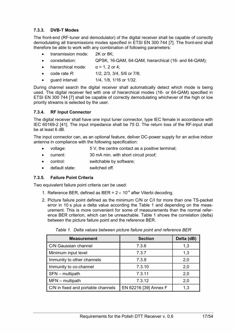
7.3.5. Failure Point Criteria
Two equivalent failure point criteria can be used:
1. Reference BER, defined as BER = 2 × 10⁻⁴ after Viterbi decoding.
2. Picture failure point defined as the minimum C/N or C/I for more than one TS-packet error in 10 s plus a delta value according the Table 1 and depending on the meas-urement. This is more convenient for some of measurements than the normal refer-ence BER criterion, which can be unreachable. Table 1 shows the correlation (delta) between the picture failure point and the reference BER.
Table 1. Delta values between picture failure point and reference BER
Measurement Section Delta (dB)
C/N Gaussian channel 7.3.6 1,3
Minimum input level 7.3.7 1,3
Immunity to other channels 7.3.9 2,0
Immunity to co-channel 7.3.10 2,0
SFN – multipath 7.3.11 2,0
MFN – multipath 7.3.12 2,0
C/N in fixed and portable channels EN 62216 [39] Annex F 1,3
18/54 Requirements for the Polish DTT Receiver v. 0.6
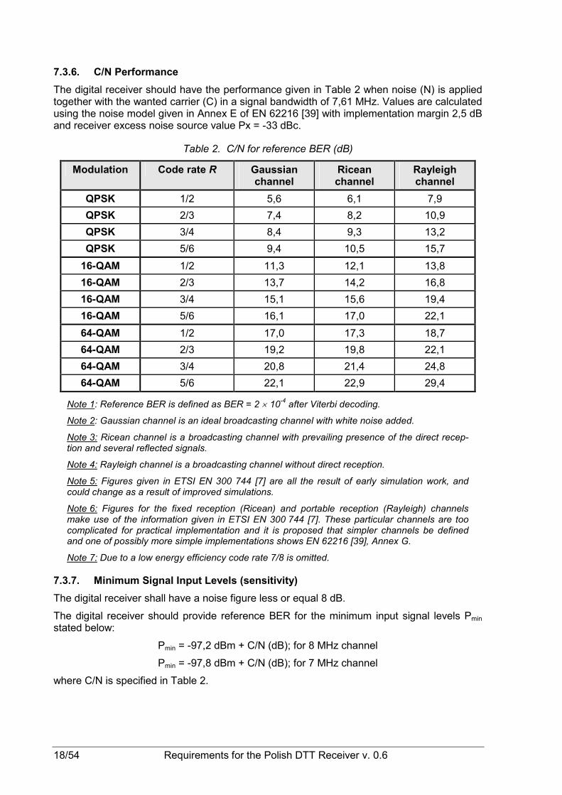
7.3.6. C/N Performance
The digital receiver should have the performance given in Table 2 when noise (N) is applied together with the wanted carrier (C) in a signal bandwidth of 7,61 MHz. Values are calculated using the noise model given in Annex E of EN 62216 [39] with implementation margin 2,5 dB and receiver excess noise source value Px = -33 dBc.
Table 2. C/N for reference BER (dB)
Modulation Code rate R Gaussian channel
Ricean channel
Rayleigh channel
QPSK 1/2 5,6 6,1 7,9
QPSK 2/3 7,4 8,2 10,9
QPSK 3/4 8,4 9,3 13,2
QPSK 5/6 9,4 10,5 15,7
16-QAM 1/2 11,3 12,1 13,8
16-QAM 2/3 13,7 14,2 16,8
16-QAM 3/4 15,1 15,6 19,4
16-QAM 5/6 16,1 17,0 22,1
64-QAM 1/2 17,0 17,3 18,7
64-QAM 2/3 19,2 19,8 22,1
64-QAM 3/4 20,8 21,4 24,8
64-QAM 5/6 22,1 22,9 29,4
Note 1: Reference BER is defined as BER = 2 × 10⁻⁴ after Viterbi decoding.
Note 2: Gaussian channel is an ideal broadcasting channel with white noise added.
Note 3: Ricean channel is a broadcasting channel with prevailing presence of the direct recep-tion and several reflected signals.
Note 4: Rayleigh channel is a broadcasting channel without direct reception.
Note 5: Figures given in ETSI EN 300 744 [7] are all the result of early simulation work, and could change as a result of improved simulations.
Note 6: Figures for the fixed reception (Ricean) and portable reception (Rayleigh) channels make use of the information given in ETSI EN 300 744 [7]. These particular channels are too complicated for practical implementation and it is proposed that simpler channels be defined and one of possibly more simple implementations shows EN 62216 [39], Annex G.
Note 7: Due to a low energy efficiency code rate 7/8 is omitted.
7.3.7. Minimum Signal Input Levels (sensitivity)
The digital receiver shall have a noise figure less or equal 8 dB.
The digital receiver should provide reference BER for the minimum input signal levels Pmin stated below:
Pmin = -97,2 dBm + C/N (dB); for 8 MHz channel
Pmin = -97,8 dBm + C/N (dB); for 7 MHz channel
where C/N is specified in Table 2.

Requirements for the Polish DTT Receiver v. 0.6 19/54
Note: Above figures are based on an ideal transmitter. An example of non-ideal transmitter figures can be achieved using the C/N-table in EN 62216 [39] Annex F “An example of C/N-performance with a practical transmitter”.
7.3.8. Maximum Input Signal Levels
The digital receiver shall be able to handle DVB-T signals up to a level of -35 dBm while pro-viding the performance specified in this section. Maximum tolerated level of analogue signals carriers is -25 dBm (84 dBµV). Both levels are valid for receivers operating on all DVB-T modes.
7.3.9. Immunity to Analogue and/or Digital Signals in Other Channels
The following performance shall be met for the wanted DVB-T signal in the channel N for (8K, 64-QAM, 2/3) and all more resistant (requiring less C/N) transmission modes.
• Signal level of D1/PAL in adjacent channel (N + 1 or N - 1) can be at most 33 dB higher than wanted signal level. In other not adjacent channels (< N - 1, > N + 1) analogue signal level can be at most 46 dB higher than the wanted signal.
• DVB-T signal in adjacent channel (N + 1 or N - 1) or image channel can be at most 30 dB higher than wanted signal level. In other not adjacent channels (< N - 1, > N + 1) level of interference DVB-T signal can be at most 40 dB higher than the wanted signal.
7.3.10. Immunity to Co-channel Interference from Analogue TV Signals
The immunity is defined as the minimum useful to interfering signal ratio (C/I) required for the reception with reference BER. For transmission mode (8K, 64-QAM, 2/3) and all more resis-tant ones this parameter shall not be higher than 3 dB.
7.3.11. Guard Interval Utilization in Single Frequency Networks
For transmission modes:
• 8K, 64-QAM, R = 2/3,
• 8K, 64-QAM, R = 3/4,
• 8K, 16-QAM, R = 1/2,
• 8K, 16-QAM, R = 2/3,
• 8K, 16-QAM, R = 3/4
and all guard intervals, the receiver shall assure the reception with reference BER when the
channel contains two static paths with relative delay from 0,2 µs up to 0,9 times the guard interval length independently of the relative amplitudes and phases of the two paths. No noise is added.
7.3.12. MFN Multipath Performance
7.3.12.1. Performance with Long Echoes
The digital receiver shall provide the reception with the reference BER when C/N ≥ 24,2 dB with the mode (2K, 64-QAM, 2/3, 1/32) when the channel profile given in the Table 3 is ap-plied. The selected mode is used as representative for the assessment the overall echo per-formance of the receiving circuit.

20/54 Requirements for the Polish DTT Receiver v. 0.6
Table 3. Long echo test profile
Tap Delay (µs) Relative attenuation (dB)
1 0 0
2 5 9
3 14 22
4 35 25
5 54 27
6 75 28
7.3.12.2. Performance with Short Echoes
The digital receiver shall provide the reception with a reference BER when C/N ≥ 24,2 dB with the mode (2K, 64-QAM, 2/3, 1/32) when the channel profile given in the Table 4 is ap-plied. The selected mode is used as representative for the assessment the overall echo per-formance of the receiving circuit.
Table 4. Short echo test profile
Tap Delay (µs) Relative attenuation (dB)
1 0,0 2,8
2 0,05 0,0
3 0,4 3,8
4 1,45 0,1
5 2,3 2,6
6 2,8 1,3
8. MPEG-2 DEMULTIPLEXER
8.1. General Requirements
Demultiplexer of the digital receiver shall be compliant to the MPEG-2 transport layer defined in ISO/IEC 13818-1 [23].
8.2. Constraints and Extensions
• the receiver shall utilize the MPEG-PSI data as specified in Annex C of ISO/IEC 13818-1 [23];
• the receiver shall interpret the CA descriptor data as defined in ETSI ETR 289 [11];
• the demultiplexer shall be able to decode an ISO/IEC 13818-1 [23] stream with data rates up to 58 Mb/s;
• the receiver shall be capable to utilise at least 32 elementary streams simultane-ously which requires 32 PID filters, in order to receive any single service;
• the demultiplexer shall provide at least 32 simultaneous section filters;
• the receiver shall use the video stream descriptor to recognise still picture data;
• the receiver shall support variable bitrate elementary streams within a constant bi-trate transport stream (excluding audio);
• the receiver shall support a mixture of service types within the same MPEG-2 trans-port stream (i.e. SDTV, HDTV and sound programmes).

Requirements for the Polish DTT Receiver v. 0.6 21/54
8.3. DVB Descrambler Performance
The descrambler unit shall be based on the common scrambling algorithm in version 2 as specified by DVB (see DVB A011 [1]). See also section 14.4.3 (ECM and EMM Filtering). It shall be able to descramble on transport level and on PES format. The digital receiver shall be able to process in parallel up to at least 6 different streams (either PES or transport level) with different access conditions. Data streams without access control shall be bypassed by the descrambling unit.
Note 1: This requirement is not applicable to the digital receivers working with an external CA module.
Note 2: ETSI acts as a neutral custodian for the distribution of the system information con-cerning the common scrambling system.
8.4. System Clock Recovery
During the system time clock (STC) acquisition audio shall be muted and video shall be black or frozen. (The transition shall be smooth and seamless when the user changes the chan-nel). The decoder shall be able to:
• recover STC using PCR with maximum jitter of ±10 µs;
• track long-term variations in the frequency of the encoder STC.
For each service, the demultiplexer shall recover the source clock by extracting the associ-ated PCR values received within the incoming multiplex and insert them into the appropriate Phase Locked Loop.
9. VIDEO DECODER
9.1. Basic Requirements
The video decoder shall able to decode digital video bitstreams encoded according to ITU-T Recommendation H.264 [48] with constraints stipulated for the receiver 25 Hz H.264/AVC SDTV and HDTV set out in ETSI TS 101 154 [14], section:
• 5.5 for all streams;
• 5.6 for MP@L3 streams with a standard resolution (SD); and
• 5.7 for HP@L4 streams with a high resolution (HD).
9.2. Constraints and Extensions
This section sets out additional requirements to the video decoder with reference to those given in ETSI TS 101 154 [14].
9.2.1. Active Format Descriptor
The digital receiver shall support Active Format Descriptor (AFD) as defined in Annex B of ETSI TS 101 154 [14].
9.2.2. Luminance Resolution
The digital receiver shall support all luminance resolutions as specified in ETSI TS 101 154 [14], section 5.6.2.3 for SD resolution and section 5.7.1.5 for HD resolution. Up-sampling of sub-sampled resolutions shall also be made in accordance with ETSI TS 101 154 [14], i.e. sub-sampled luminance resolutions shall be up-converted into the video raster selected by
the viewer from among: 1920 × 1080, 1280 × 720 or 720 × 576. For an iDTV all resolutions shall be converted to the native resolution of the screen.

22/54 Requirements for the Polish DTT Receiver v. 0.6
When up-converting the 720 × 576 resolution to any square pixel format (i.e. 1920 × 1080 or
1280 × 720) only the centred 702 pixels of the horizontal 720 shall be used. Those 702 pixels correspond to the 52 µs of an active line, hence preserves correct geometry in the up-conversion process.
When up-converting other valid input line resolution format to any square pixel format (i.e.
1920 × 1080 or 1280 × 720) only the centred horizontal pixels shall be used; e.g. when up-
converting 544 × 576 line resolution format to any square pixel format, only the centred 530 pixels of the horizontal 544 shall be used.
9.2.3. Display Mode for 16:9 Material on 4:3 Monitors
The viewer shall be able to choose at least one of the following storable display mode pref-erences:
1. display 16:9 material as „letterbox” using full width of the screen.
2. display a centre-cut of the picture using full height of the screen.
In addition the viewer shall be able to enable or discard the AFD operation when this mode is available for the receiver. If the AFD is enable and valid AFD data is received the above set-tings shall be overridden.
9.2.4. Displaying 4:3 Material on 16:9 Monitors
The digital receiver shall signal the 4:3 material as specified in section 13.4.1 for SCART sig-nalling and equivalent for the iDTV.
The viewer shall be able to enable or discard usage of the AFD.
9.2.5. 16:9-letterbox Conversion
16:9 letterbox conversion (i.e. 16:9 broadcast, which the IRD converts into 16:9 letterbox in-side a 4:3 frame raster edge) shall be implemented for the display of video using the 16:9 aspect ratio on 4:3 monitors. This conversion shall be implemented by vertical filtering. Sig-nal degradation due to the filtering should be subjectively imperceptible. Line 23 and line 623 should be masked before the letterbox conversion to avoid the irritating half lines.
9.2.6. Down-conversion
The receiver shall support down-conversion from any valid full input resolution (720 × 576,
544 × 576, 480 × 576, 352 × 576 or 352 × 288 pixels) to 1/4 respective 1/16 of displayed
screen size (352 × 288 or 176 × 144). It shall be possible to locate the down-converted video anywhere on the screen.
Note 1: Not applicable for the Profile 0.
Note 2: The control of down-conversion (size and position) is handled by DVB-MHP API.
9.2.7. Up-conversion
Up-sampling of video shall be supported from any valid full input resolution (720 × 576,
544 × 576, 480 × 576, 352 × 576 or 352 × 288 pixels) to the any valid resolution. It shall be possible to locate the up-converted video anywhere on the screen.
Note 1: Up-conversion to other values than full 720 × 576 is optional for the Profile 0.
Note 2: The control of up-conversion (size and position) is performed by DVB-MHP API.

Requirements for the Polish DTT Receiver v. 0.6 23/54
9.2.8. Default Location Mode
If no application requests a specific location of the up-converted video the following default mode shall apply:
An input video with the resolution 704 × 576 shall not be up-sampled, thus it shall be located as indicated below.
If the result of the up-sampling process is less than 720 pixels wide then the output of the video decoder shall be centred within the region of 720 active digital video pixels. The offset from the start of the active digital video pixel area to the first (left most) pixel of video decoder output is the difference in their widths divided by 2 and truncated towards zero. Equivalent centring should be used to position the video decoder vertically within the 576 active lines of the analogue display.
If the result of the up-sampling process is greater than 720 pixels wide then the output of the video decoder shall be cropped symmetrically to fit within the region of 720 active video pix-els. The number of pixels cropped from the left-hand side of the video decoder output shall be the difference between its width and 720 divided by 2 and truncated towards zero. The remaining difference shall be cropped from the right hand side of the video decoder output.
9.2.9. Still Pictures Support
The digital receiver shall support the decoding and displaying of still pictures (frame) for all valid AVC profiles. A still picture is a video sequence containing exactly one intra-coded pic-ture. Such a video stream will cause the buffer to underflow. In this situation, while the de-coding process shall continue to examine the buffer, the display process associated with the decoder shall repeat the previously decoded picture until the normal operation of the buffer can resume.
For the signalling of the still picture the AVC descriptor in PMT will be used as specified in ISO/IEC 13818-1 [23] (the flag AVC_still_present will be set).
9.2.10. Video Minimum Bitrate
The digital receiver shall be able to decode video streams down to 250 kb/s. Still pictures transmitted with the minimum bitrate of 100 kb/s shall also be correctly decoded.
9.2.11. HDMI Video Output and HD Display
The STB shall be able to use the EDID information provided by the display module to deter-mine automatically the STB output and to accept a manual setting of the STB output, as specified in section 13.3.1.
For iDTVs the IRD output video shall always be converted to the display’s native resolution.
9.2.12. Analogue Video Output (optional for iDTV)
The digital receiver shall deliver video signal with SD resolution only, at any analogue video output, regardless of the resolution of the incoming signal.
Down-conversion of pictures to SD resolution 720 × 576 shall be implemented, from any of
the incoming encoded HD full screen luminance resolution values (1920 × 1080,
1440 × 1080, 1280 × 1080, 960 × 1080, 1280 × 720, 960 × 720 and 640 × 720).
When down-converting any format using the square pixel (i.e. 1920 × 1080 or 1280 × 720) to
720 × 576 resolution, the target shall be 702 × 576 pixels to be centred in the 720 × 576 grid with nine black pixels inserted as the start of the 720 pixel active line and nine pixels inserted as the end of the 720 pixel active line.
Down-converted HD video shall be displayed as 16:9 letterbox on 4:3 displays.

24/54 Requirements for the Polish DTT Receiver v. 0.6
10. AUDIO DECODER
10.1. Basic Requirements
The audio decoder shall be able to decode digital audio bitstreams encoded according to MPEG-2 Layer II in compliance with ISO/IEC 13818-3 [24] constrained according to ETSI TS 101 154 [14], section 6.1 and E-AC-3 in compliance with ETSI TS 102 366 [18] constrained according to section 6.2.
In all cases the number of audio channels for the single service shall be limited to 5.1.
10.2. Scope of Requirements
These requirements on audio signals apply to applications including, but not limited to, those listed below:
• primary and other language audio channels for TV programmes;
• sound broadcasting services;
• audio description (for the visually impaired);
• clean dialogue (for the hearing impaired).
10.3. Constraints and Extensions
10.3.1. Audio/Video Synchronization
The digital receiver shall not introduce more then ±5 ms of relative delay between the video and any audio component (relative to the times indicated by their respective PTSs).
10.3.2. Audio Metadata
The digital receiver shall be able to correctly receive and interpret the Dolby metadata trans-mitted in the AC-3 or E-AC-3 audio bitstreams in order to:
• normalise the level of the audio between different services;
• downmix any multichannel audio to stereo;
• mix any secondary decoded audio bitstream with the main decoded audio stream.
10.3.3. Analogue Audio Output
Regardless of the coding system and the number of the transmitted audio channels the de-coder shall deliver the stereo signal at each analogue audio output of the receiver unless a mono or dual sound is transmitted. Then the decoder shall deliver a mono sound selected by the user at both channels.
10.3.4. Digital Audio Output
10.3.4.1. HDMI (STB only)
The digital receiver shall deliver following data formats on the HDMI output:
• pass-through of a native bitstream (AC-3 or E-AC-3);
• E-AC-3 bitstream transcoded to AC-3 stream;
• LPCM stereo bitstream from decoded or down-mixed bitstream.
10.3.4.2. S/PDIF
The digital receiver shall deliver following data formats on the S/PDIF output:
• pass-through of AC-3 bitstream;
• E-AC-3 bitstream transcoded to AC-3 stream;

Requirements for the Polish DTT Receiver v. 0.6 25/54
• LPCM stereo bitstream from the decoded or down-mixed bitstream.
The digital audio output shall always give either a valid LPCM output according to IEC 60958 [35] or a non-PCM encoded audio bitstream according to IEC 61937 [38]. The user shall be able to choose between the following storable output modes on the digital audio output inter-face:
1. Forced LPCM output according to EN 60958 [35].
2. Non-audio-data output according to IEC 61937 [39] when present and if not present output LPCM according to IEC 60958 [35]. Non-audio-data-formats like AC-3 shall be possible to order and enable/disable according to priority set by the user.
Note 1. If the receiver can also receive analogue PAL transmissions and NICAM-stereo (if present) or alternatively analogue audio shall be AD-converted to LPCM-audio as stereo or 2 channels of mono to be output at the S/PDIF interface.
Note 2. The requirement of the presence of the S/PDIF interface does not refer to the digital receiver with at least 5 analogue audio outputs for the surround sound.
10.3.4.3. Audio Prioritising
The factory default settings of the IRD for digital audio output shall be LPCM-stereo accord-ing to IEC 60958 [35]. The IRD shall provide output formats in accordance with Table 5. The user shall be able to select multi-channel audio for the digital outputs, when the outputs are equipped for multi-channel audio.
Table 5. Audio formats presentation on digital outputs
Default (stereo) Multichannel audio Available combinations of the input formats S/PDIF and HDMI S/PDIF HDMI
MPEG-2 Layer II LPCM LPCM LPCM
AC-3 LPCM AC-3 AC-3
MPEG-2 Layer II and AC-3 LPCM AC-3 AC-3
E-AC-3 LPCM E-AC-3 transcoded to AC-3
E-AC-3
MPEG-2 Layer II and E-AC-3 LPCM E-AC-3 transcoded to AC-3
E-AC-3
Note 1: When an HDMI-Sink device indicates in its E-EDID structure that it only supports Basic Audio (i.e. two-channel LPCM from the original stereo signal or from a stereo down-mix from the multi-channel signal), then the HDMI output will provide Basic Audio.
Note 2: If an HDMI-Sink device indicates in its E-EDID structure that AC-3 decoding is sup-ported, but E-AC3 decoding is not supported, the IRD shall transcode E-AC-3 streams to AC-3 prior to HDMI transmission.
10.3.5. Audio Handling when Changing Audio Streams
The digital receiver shall be able to read and use the ISO 639-2 [21] language descriptors associated with the audio-streams in the ISO/IEC 13818-1 [23] MPEG-2 transport stream.
The user shall be able to select storable preferences for primary and secondary audio lan-guage. If an audio-stream according to the primary audio language preference is not associ-ated with the chosen service the IRD shall automatically choose the audio stream according to the secondary audio language preference, if present. In addition the user shall be able to manually select between all audio-streams that are associated with the active service.

26/54 Requirements for the Polish DTT Receiver v. 0.6
The IRD shall be able to handle dynamic changes of audio component(s) (PID/PIDs) in a service. The IRD shall automatically identify if an audio component is added or removed be-tween two programme events in the same service. The IRD should have minimum distur-bance for such changes of audio format.
The IRD shall be able to handle the following dynamic changes without user interaction and start decoding within 1 s after reception of a change (like PMT update, elementary stream header signalling):
• change of number of audio channels (e.g. from mono to stereo and vice versa);
• change of bitrate for an audio component;
• change of audio PID value (e.g. for regional inserts);
• change from dual channel audio into mono or stereo and vice versa;
• removal of one audio component (PID), the IRD shall use next preferred audio stream;
• addition of one audio component with higher preferred user settings.
The IRD shall handle the dynamic changes after change of selected service (zapping) (i.e. shall not require to re-install services) and shall be able to handle the following dynamic changes without user interaction and start decoding within 1 s after reception of change:
• change of an audio codec (e.g. change from MPEG-2 Layer II into E-AC-3);
• change of the ISO 639-2 [21] language for an audio component.
The IRD shall be able to read the audio information contained in DVB_stream_content and component_type of the component descriptor of defined in EN 300 468 [2]. The IRD should be able to present the audio information, including the descriptors for audio description for the visually impaired and audio for the hard of hearing, contained in the component descrip-tor to the user for information and selection purposes.
10.3.6. Adjustment of Video/Audio Delay
The STB shall support the possibility to adjust the audio-delay on the S/PDIF output up to 250 ms in 10 ms steps, in order to set delays introduced by different audio amplifiers or ex-ternal displays connected to the STB.
10.3.7. Audio Handling when Changing Service or Audio Format
The digital receiver should gracefully handle change of service or audio format at the audio output without audible disturbances to the end user.
10.3.8. IRD Internal Reference Level
The digital receiver shall have an internal digital audio reference level equivalent to the Dolby dialogue normalization reference of -31 dBFS (equivalent to -20 dBFS Leq(A) for the ana-logue outputs.
The digital receiver shall adjust the output level of all audio decoders to match the internal reference level so that perceived programme loudness is consistent for all audio coding schemes. When decoding E-AC-3 stream the IRD shall be consistent with Dolby Technical Bulletin 11 [61]. The digital receiver shall include the PCM Level Control feature described therein.

Requirements for the Polish DTT Receiver v. 0.6 27/54
11. TELETEXT AND DVB SUBTITLES
11.1. Teletext
During decoding of the audio, video and data bitstreams, the digital receiver shall be able to demultiplex in parallel the teletext service transmitted in packetised format according to ETSI EN 300 472 [4].
The IRD shall be able to receive teletext data meeting ETSI EN 300 706 [5] (enhanced teletext specification - Level 1.5 for Polish language) and support following operation modes:
• active mode: Teletext is decoded by the receiver and display using OSD, or
• passive mode (STB only): Teletext data are inserted in the lines 6 to 22 and 320 to 335 during VBI of the CVBS output signal according to ETSI EN 300 706 [5].
11.2. DVB Subtitles
The digital receiver shall be able to decode and display the DVB subtitles transmitted with SD or HD resolution according to ETSI EN 300 743 [6] and with following additional require-ments:
• mandatory presence of EDS segment;
• mandatory presence of DDS in HD transmissions, where maximum_display_with shall be 1919 and maximum_display_hight shall be 1079;
• presence of objects type (0x00) ‘basic object, bitmap’;
• number of objects shall not exceed 128 for bitstreams without DDS and 256 for bit-streams with DDS.
In the case that both of DVB and teletext subtitles are available with the same language and type parameters then, displaying the DVB subtitles has priority over displaying the teletext subtitles.
The user shall be able to select default and preferred primary and secondary language of the DVB subtitles.
12. GRAPHICS PROCESSOR The digital receiver shall support an OSD graphics meeting following requirements:
12.1. Profile 0
1. The STB shall support a minimum graphics resolution of 1280 x 720 pixels. The iDTV shall support a minimum graphics resolution of half the horizontal and vertical native resolution of the display. It is recommended that all receivers support graphics resolu-tion of 1920 x 1080 pixels.
2. Support at least one colour look-up table (CLUT) with a minimum of 16 entries includ-ing transparency. It should be possible to choose any 24-bit RGB colour into the 16 entries.
3. Support 2 logical displays planes:
a) video plane for full screen video,
b) graphic plane for graphics (used for menus, teletext, DVB subtitles etc.).
4. Support blending of the graphics with video or stills backgrounds. At least 3 levels of transparency shall be provided (0%, 30%, 100%).
5. Support aspect ratios as set in the installation setting (at SCART-TV interface or equivalent for iDTV).

28/54 Requirements for the Polish DTT Receiver v. 0.6
12.2. Profile 1 and 2
1. Support resolution of 1920 x 1080 pixels and lower.
2. Support at least one colour look-table (CLUT) with a minimum 256 entries including transparency. It should be possible to choose any 24-bit RGB colour into the 256 en-tries. The actual presentation shall be specified as defined in the DVB-MHP specifica-tion.
3. Support simultaneously 3 logical display planes:
a) graphic plane I for MPEG-I still frames, JPEGs, GIFs, PNGs or decimated live video;
b) video plane for full screen video,
c) graphic plane II for full screen graphics.
4. Support blending of the graphics with video or stills backgrounds. At least 16 levels of transparency shall be provided.
5. Support aspect ratios for SDTV signals as set in the installation setting (at SCART-TV interface or equivalent for iDTV).
13. INTERFACES AND SIGNAL LEVELS OF THE RECEIVER
13.1. Introduction
This chapter includes electric requirements to external interfaces of the digital receiver, ex-cept for the RF-tuner and demodulator that are described in chapter 7.
The specification is based on ETSI TS 102 201 [17] describing recommended interfaces used for the connection of the digital receiver with external devices and RF signals.
13.2. Analogue TV Reception (option)
The digital receiver should support analogue TV reception, particularly in the first phase of digitization of the transmission, when not all analogue TV services be accessible in digital form from the beginning.
It can be done by one of the following manner:
1. by embedding in parallel one analogue TV demodulator, a combiner for mixing of CVBS with the OSD and switches to allow the CVBS and associated audio to appear at the SCART and audio output.
2. by embedding an RF loop-through providing with split the RF input signal at the RF output and further to the RF antenna input of the analogue TV-set.
13.2.1. RF Loop-through
The STB should be equipped with RF loop-through for splitting of RF input signal. The RF signal shall be available at the output connector, type IEC male in accordance with IEC 60169-2 [41]. The output impedance shall be 75 Ω. The return loss of the RF output shall be at least 6 dB.
RF signal level at the antenna output shall be less than 3 dB below and les than 3 dB above the RF signal at the antenna input, measured over the complete RF bandwidth from 110 to 862 MHz. The overall S/N degradation introduced by the RF loop-through shall be less than 1 dB.
The noise factor of the RF loop-through shall be less or equal 9 dB, CSO/CTB shall be in conformity with values given in EN 50083-7 [26], section 5.7.3, i.e.:

Requirements for the Polish DTT Receiver v. 0.6 29/54
• -57 dB for every group of composite intermodulation products with negative modula-tion;
• -52 dB for every group of composite intermodulation products with positive modula-tion;
• -52 dB for negative modulation and 47 dB for positive modulation for added up groups, calculated in compliance with EN 50083-7 [26].
The RF signals shall be by-passed from the RF antenna input to the output independently from the status of the digital receiver (operational or stand by) so that connected equipment (e.g. TV-set) can operate even the digital receiver is in stand by.
Note: The composite D1/PAL TV-signal from the local modulator can be connected to the RF antenna output.
13.2.2. Output of Composite D1/PAL TV-signal
The STB should have a double sideband modulator according to ITU-R Recommendation BT.1701 [45] for the D1/PAL standard and parameters given in Table 6:
Table 6. Electrical performance of TV modulator
Parameter Min Max Unit
TV Standard D1/PAL
Video frequency tuning range TV channel 21-69
Output impedance 75 Ω
Video carrier level 64 74 dBµV
Audio to video carrier level ratio -17 -13 dBc
Sound carried deviation 50 kHz at -9 dBFS
Signal to nose ratio ≥ 45 dB
Modulation depth 74 86 %
Video frequency inaccuracy -150 150 kHz
Differential audio frequency inaccuracy -2 +2 kHz
Spurious emissions level -45 - dBc
13.3. Digital Interfaces
13.3.1. HDMI Interface
13.3.1.1. General Requirements
The STB shall have the HDMI output with type A connector conforming with requirements of “High-Definition Multimedia Interface” [55].
13.3.1.2. Video Output
The STB shall be able to use the EDID information provided by the display module to auto-matically determine of the HDMI output parameters.
The STB shall provide an “Original Format” option, i.e. to output the same format as received if supported by the display, as indicated by the EDID information. If the received format is not supported, the STB should select the display mode providing the best possible video quality. This is to avoid the STB output to go black, if there is a mismatch between received format and display capabilities.

30/54 Requirements for the Polish DTT Receiver v. 0.6
It shall also be possible to manually set the default output format from the received format to a fixed format. The fixed format shall include at least one of the following formats:
1280 × 720p50 Hz, 1920 × 1080i25 Hz/1920 × 1080p25 Hz and 1920 × 1080p50 Hz.
The preferred default output shall be stored in the STB memory.
13.3.1.3. Audio Output
According to rules described in section 10.3.4.3.
13.3.1.4. HD Signal Protection
The HDMI interface shall be protected against unauthorized access to audio-visual content by the HDCP system according to “High-Bandwidth Digital Content Protection System” [56].
The received service may be flagged with a need for content protection or not (CP “ON” or “OFF”) via either the PMT-table or the CA-system or both, as specified by the relevant net-work/CA-operator.
Signals that the IRD is entitled to receive shall be sent to the HDMI-sink (display) in accor-dance with the following conditions:
1. In case the received service is flagged with no need for content protection, the signal may be sent to the sink with HDCP disabled. In case both the PMT-table and the CA-system are used for signalling of such flag, and the HDCP is set to ”OFF”, the signal shall only be sent to the sink when both the flag received via the PMT-table and the flag received via the CA-system indicate no need for content protection.
2. In case the received service is flagged with content protection required via either the PMT-table or the CA-system, the signal shall only be sent to the sink with the HDCP enabled, i.e. when the HDMI sink satisfies the HDCP requirements and HDCP pro-tection is established on the HDM-Ilink.
STB shall provide an option for setting the preferred HDCP state (HDCP-user setting) to ei-ther „ON” or „OFF”. The „HDCP-user setting” shall apply to all services receivable by STB.
13.3.2. S/PDIF Interface
The digital receiver shall have the S/PDIF interface with a coaxial (RCA) or optical (TOS-LINK) connector according to EN 60958 [35] and IEC 61937 [38].
Note. This requirement does not refer to the digital receiver with at least 5 analogue audio outputs for the surround sound.
13.3.3. Return Channel Interface
The digital receiver of the Profile 2 shall support at least one of the following return channel interfaces:
• Ethernet according to IEEE 802.3 [50] (at least 100Base-T, Auto-sense DHCP);
• WLAN according to IEEE 802.11, b, g [51];
• the V.90 modem [49] (56 kb/s).
13.3.4. Data Interface (option)
The digital receiver should support local data interface from mentioned below:
• RS-232C – according to ETSI TS 102 201 [17] section 4.7.1;
• USB 2.0 – according to [58];
• Ethernet – according to IEEE 802.3 [50] (at least 100Base-T);
• WLAN – according to IEEE 802.11 [51];

Requirements for the Polish DTT Receiver v. 0.6 31/54
• Bluetooth 2.0 – according to [53];
• FireWire – according to IEEE 1394 [52].
Note. The output from the local data interface shall only allow data as broadcast, without any change of access control. I.e. it shall not t include any data or bitstreams that have been de-scrambled/removed of access control introduced by the relevant CAS operator.
13.4. Analogue Interfaces
13.4.1. SCART Interfaces
The STB shall have in at least one SCART interface in accordance with EN 50049-1 [25] and EN 50157-2-1 [27].
Table 7shows which signals shall be accessible on the SCART interfaces.
Table 7. SCART interfaces requirements
SCART Presence CVBS/Audio RGB Pin 8 Pin 16
1. TV Mandatory Output Output Output Output
2. VCR Optional Input and Output Input Input Input
Note 1: OSD graphics should not be present on the SCART-VCR output except for the DVB subtitles (if present and chosen).
Note 2: Control voltages applied to the pin 8 or 16 of the SCART-VCR input should be for-warded to suitable pins of the SCART-OTV output.
Note 3. Control voltages of the SCART interface are defined as follows:
Pin 8: nom. 0 V: internal source of the TV-set; nom. 6 V: external source, 16:9 format; nom. 12 V: external source, 4:3 format.
Pin 16: nom. 0 V: CVBS active mode; 1-3 V: RGB active mode.
Note 4. The difference in delay between the CVBS and RGB signals should be user adjustable
by up to at least ±1,5 µs.
13.4.2. YPbPr Video Output (option)
The digital receiver may have one analogue video output in the YPbPr format in confor-mance with CEA-770.3, High Definition TV Analogue Component the Video Interface [54]. Regardless of the input signal resolution, the decoder shall always deliver the SD resolution signal in compliance with requirements of section 9.2.12.
13.4.3. Audio Interfaces (option)
13.4.3.1. SCART-VCR Connector
The audio interface SCART for analogue recording (SCART-VCR) shall deliver the same au-dio signal as available at the SCART interface for the TV-set (SCART-TV). The internal vol-ume control should only affect the audio signal at SCART-TV interface, but not the audio sig-nal of the SCART-VCR audio interface.
13.4.3.2. RCA Connector
The audio interface using the RCA connector should have two RCA sockets conforming with IEC 60603-14 [42]. Audio output signals shall meet the requirements of section 10.3.3.

32/54 Requirements for the Polish DTT Receiver v. 0.6
13.5. Remote Control Interface
The digital receiver shall have remote control. Manufacturer will determine the RCU interface and its functionality.
Minimum-requirements for the RCU are defined in Annex B.
13.6. Cordless Keyboard Interface (option)
The receiver of the Profile 2 should have a cordless keyboard interface.
14. INTERFACES FOR CONDITIONAL ACCESS
14.1. General Remarks
The digital receiver should be prepared to receive existing and future pay-TV services. This requires that the receiver can accommodate Conditional Access (CA) systems chosen later by service providers.
14.2. Minimum Requirements
To enable receivers with a built-in CA-system to receive additional services via simulcrypt techniques the DVB Common Scrambling Algorithm shall be implemented according to ETSI ETR 289 [11]. It is recommended that CA-modules support simulcrypt on the same basis.
The digital receiver should implement the DVB Common Interface (CI) to allow later adoption of a CA system by means of a plug-in CA-module. The iDTV-sets with screen diagonals lar-ger than 30 cm shall be equipped with at least one DVB-CI slot complying with following ETSI and CENELEC standards:
• DVB A011 rev.1 [1],
• EN 50221 [29],
• ETSI ETR 289 [11],
• CENELEC R206-001 [59],
• ETSI TS 101 699 [15].
Profile 2 as defined in ETSI TS 101 699 [15] shall be implemented as minimum. With respect to features being mandatory or optional, the guidelines in R206-001 [59] shall only be inter-preted as further refinements on EN 50221 [29] and ETSI TS 101 699 [15] to improve inter-operability, not as functional extensions to EN 50221 [29] and ETSI TS 101 699 [15]. This is also stipulated in the profile definitions of ETSI TS 101 699 [15].
If the CA-system on the CI-module requires a smart-card reader, this reader shall be imple-mented on the CI-module.
The conditional access may be also supported by the CA built-in system with the smart-card reader.
Note. It is recommended, for the user convenience, to choose a common CA-system for all paid services delivered within one digital platform.
14.3. Use of the DVB-CI
14.3.1. General Remarks
The DVB-CI can be used to the conditional access and other purposes. The CA-module may be inserted in the CI-slot of the digital receiver in order to provide access control of the in-coming services.

Requirements for the Polish DTT Receiver v. 0.6 33/54
14.3.2. Minimum Requirements for the CI
Each CI-slot shall meet the specification EN 50221 [29] and be prepared for modules of type 2.
14.3.3. Minimum-Requirements for CA-Modules
14.3.3.1. General Requirements
The CA-module may contain the CA security device (“CA-module with fully embedded CA-system”) or a smart-card interface for connection to an external smart-card (“CA-module with partly embedded CA-system”).
14.3.3.2. CAM with fully embedded CAS
The CA-module will be CA-system specific and contain all CA-functions, including the secu-rity device. For this case the relevant specifications have to be obtained from the relevant CA-system vendor.
14.3.3.3. CAM with partly embedded CAS
The CAM will be connected to a security device (smart-card). The CAM shall provide the CI-functions specified in EN 50221 [29] and the additional functions specified by the relevant CA-system vendor for the smart-card interface.
14.4. Use of Smart-Card Reader
14.4.1. General Requirements
The smart-card hardware with associated software can be used for conditional access and other purposes. This section will only consider use related to conditional access.
The smart card reader shall support an interface as partially specified in section 14.3.2 below and hardware/firmware for descrambling as specified below.
The digital receiver shall be capable of replacing the CA-system software by download of new IRD and CA-system software via the bootloader, over air or locally.
14.4.2. Smart-Card Interface
14.4.2.1. All Digital Receiver Profiles
The digital receiver should include at least one embedded smart-card reader for use with conditional access and/or other applications.
The smart card interface shall comply with ISO/IEC 7816 Part 1-3 [20]. The support of syn-chronous cards is not required. The receiver shall implement all aspects related to asynchro-nous cards with following exceptions:
• support for Vpp is not required,
• support for AFNOR pin-outs is not required,
• Vcc range is 5 V ±5%,
• Icc max is 65 mA.
The clock frequency shall be at least 5 MHz.
The possibility of using the data exchange protocol T = 0 shall be supported. It shall be pos-sible to include support for the data exchange protocol T = 1 through an IRD software up-grade.
14.4.2.2. Profiles 1 and 2
The smart-card interface of the interactive receiver shall support the non-CA smart card API as defined in DVB-MHP and CA functions, in addition to the requirements in section 14.4.2.1.

34/54 Requirements for the Polish DTT Receiver v. 0.6
14.4.3. ECM and EMM Filtering
The digital receiver shall implement ECM and EMM acquisition in accordance with ETSI ETR 289 [11].
The digital receiver shall be able to simultaneously acquire at least two ECM streams. The ECMs shall be filtered based on PID, TID and toggle bit.
The receiver shall be able to acquire EMMs from at least one EMM stream (one PID). The EMMs shall be filtered based on PID, TID and section address field. The section address field is CA system specific, and described as part of the smart card application interface. The IRD shall be able to filter on three TID and address field combinations simultaneously.
14.4.4. Descrambling of Selected Services
The receiver shall implement descrambling of selected services, see also section 8.3.
14.4.5. Application Level Interface for CA
The application level smart card interface for conditional access is CA-system specific. The application level interface definitions are restricted information that can be obtained from relevant CA-system vendors. It should be possible to add the support of other application of the interface of the conditional access through the upgrade of the receiver software.
The interactive receiver shall support the CA interface application level defined in the specifi-cation of DVB-MHP.
15. ELECTRICAL PERFORMANCE
15.1. Introduction
In this chapter the performance of decoded digital video and audio signals at the analogue outputs of the digital receiver are specified.
15.2. Video Performance of RGB and PAL Signals
RGB and CVBS signals at the appropriate interfaces of the digital receiver shall meet charac-teristics given in the Recommendation ITU-R BT.1700 [44]. The digital receiver shall at least satisfy the performance as stated in Table 8.

Requirements for the Polish DTT Receiver v. 0.6 35/54
Table 8. Video performance of digital receiver
Parameter Min Max Unit
S/N weighted, acc. ITU-T Rec. J.61 [48] 54 dB
Output impedance tolerance (relative to 75 Ω) ±10 %
Bar amplitude tolerance (relative to 700 mV) ±1 dB
Sync pulse tolerance (relative to 700 mV) ±1 dB
Burst amplitude tolerance (relative to 700 mV) ±1 dB
2T pulse response 5 %
Amplitude Characteristics (0,1-4,8 MHz) ±3 dB
R, G, B, PAL nonlinearity 6 %
Chroma/Luma intermodulation 5 %
Intercomponent level inequality (RGB) ±0,5 dB
Intercomponent timing (RGB) 40 ns
Local oscillator phase noise at 10 kHz -80 dBc/Hz
15.3. Audio Performance of Decoded Digital Signal
Reference for the performance of all audio measurement is 12 dB below full scale. All mea-surement shall be made at a sampling rate 48 kHz.
The digital receiver shall at least satisfy the performance as stated in Table 9.
Table 9. Audio performance of digital receiver
Parameter Min Max Unit
Output impedance 1000 Ω
Output level 500 2000 mVRMS at 1 kΩ
Flatness of amplitude response in band: 40-80 Hz 80-13 500 Hz 13,5-20 kHz
-2 -1 -2
+2 +1 +2
dB
Dynamic range 80 dB
Harmonic distortion ratio 0,1 %
Cross-talk between channels in band 20 Hz to 20 kHz -60 dB
Hum suppression 60 dB
S/N (weighted, quasi peak, acc. ITU-R Rec. BS.468 [43] 66 dB
Phase difference between channels in band: 40-13 500 Hz 13,5-15 kHz
10 15
deg
Amplitude difference between channels in band 20 Hz to 20 kHz
±1 dB
Volume control range 6 dB
Signal attenuation at mute 70 dB
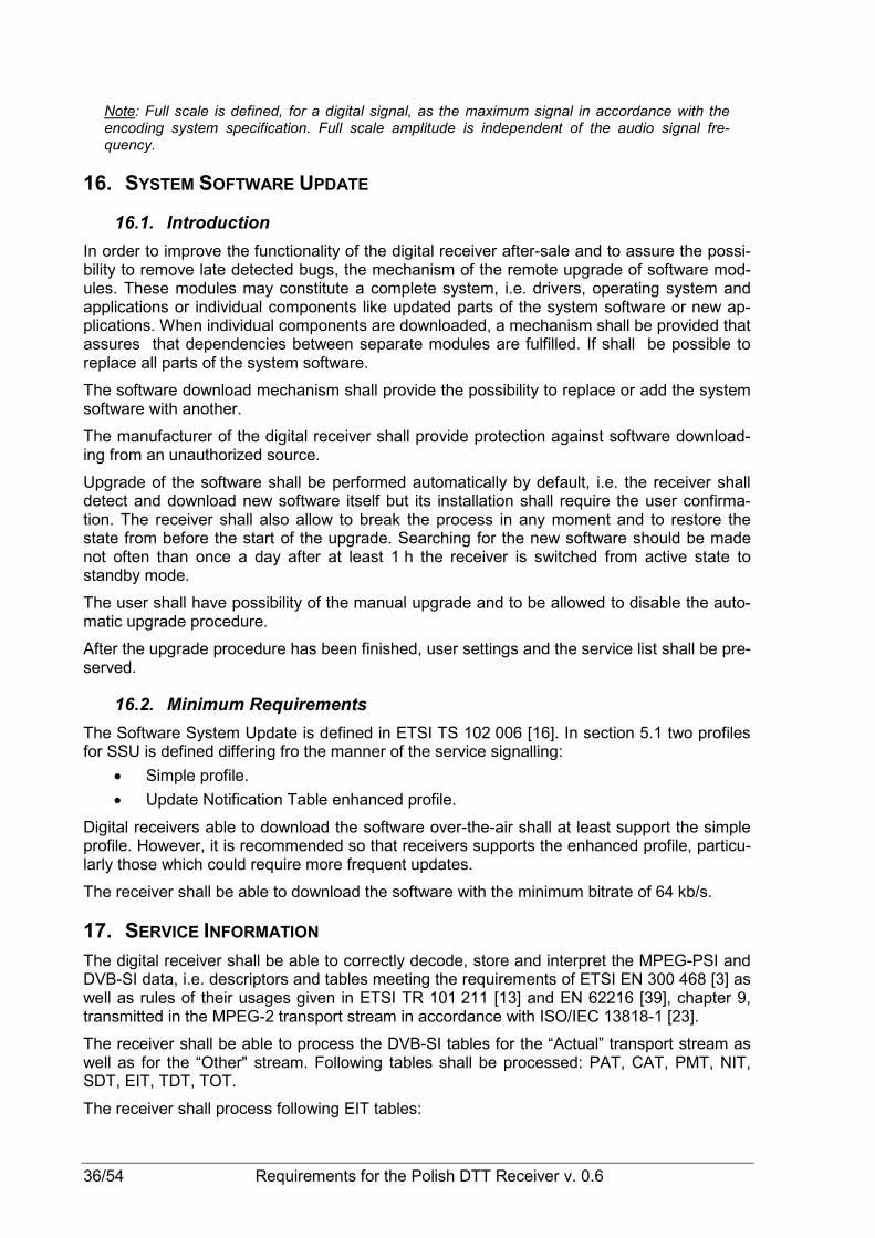
36/54 Requirements for the Polish DTT Receiver v. 0.6
Note: Full scale is defined, for a digital signal, as the maximum signal in accordance with the encoding system specification. Full scale amplitude is independent of the audio signal fre-quency.
16. SYSTEM SOFTWARE UPDATE
16.1. Introduction
In order to improve the functionality of the digital receiver after-sale and to assure the possi-bility to remove late detected bugs, the mechanism of the remote upgrade of software mod-ules. These modules may constitute a complete system, i.e. drivers, operating system and applications or individual components like updated parts of the system software or new ap-plications. When individual components are downloaded, a mechanism shall be provided that assures that dependencies between separate modules are fulfilled. If shall be possible to replace all parts of the system software.
The software download mechanism shall provide the possibility to replace or add the system software with another.
The manufacturer of the digital receiver shall provide protection against software download-ing from an unauthorized source.
Upgrade of the software shall be performed automatically by default, i.e. the receiver shall detect and download new software itself but its installation shall require the user confirma-tion. The receiver shall also allow to break the process in any moment and to restore the state from before the start of the upgrade. Searching for the new software should be made not often than once a day after at least 1 h the receiver is switched from active state to standby mode.
The user shall have possibility of the manual upgrade and to be allowed to disable the auto-matic upgrade procedure.
After the upgrade procedure has been finished, user settings and the service list shall be pre-served.
16.2. Minimum Requirements
The Software System Update is defined in ETSI TS 102 006 [16]. In section 5.1 two profiles for SSU is defined differing fro the manner of the service signalling:
• Simple profile.
• Update Notification Table enhanced profile.
Digital receivers able to download the software over-the-air shall at least support the simple profile. However, it is recommended so that receivers supports the enhanced profile, particu-larly those which could require more frequent updates.
The receiver shall be able to download the software with the minimum bitrate of 64 kb/s.
17. SERVICE INFORMATION The digital receiver shall be able to correctly decode, store and interpret the MPEG-PSI and DVB-SI data, i.e. descriptors and tables meeting the requirements of ETSI EN 300 468 [3] as well as rules of their usages given in ETSI TR 101 211 [13] and EN 62216 [39], chapter 9, transmitted in the MPEG-2 transport stream in accordance with ISO/IEC 13818-1 [23].
The receiver shall be able to process the DVB-SI tables for the “Actual” transport stream as well as for the “Other" stream. Following tables shall be processed: PAT, CAT, PMT, NIT, SDT, EIT, TDT, TOT.
The receiver shall process following EIT tables:

Requirements for the Polish DTT Receiver v. 0.6 37/54
• EIT actual (present/following/scheduled),
• EIT other (present/following/scheduled).
The digital receiver of the Profile 1 and 2 shall additionally process data delivered by the DVB-MHP API in version 1.2 with all additions for DVB-SI defined in compliance with ETSI TS 102 590 [19].
Descriptors or other data structures illegible for the receiver shall be skipped and shall not cause any harm.
18. NAVIGATOR
18.1. General Requirements
The digital receiver shall implement the a basic Navigator function, which provides the user access to the services information and allows the user to control the operation of the re-ceiver. The navigator is by definition part of the system software. A minimum functionality is required as specified below.
The Navigator shall include a service list function and a basic Event Schedule Guide (ESG) described in ETSI EN 300 468 [3]. The Navigator shall also initiated bootloading, as de-scribed in chapter 16.
The Navigator shall support the Polish language at all menu levels of the digital receiver and correctly display characters of the Polish alphabet transmitted in SI/PSI tables encoded in compliance with ISO/IEC 8859-2 [22] (ISO Latin 2).
18.2. Service List
18.2.1. Service List Requirements
The digital receiver shall maintain a service list based on DVB -SI. The receiver univocally identifies a DVB service by the unique combination of three elements:
• original_network_id,
• transport_stream_id,
• service_id.
Note. In order to assure the correct operation of receivers, broadcasters and network opera-tors are recommended to coordinate the usage of each codes and their ranges.
The services list shall include the services and should also include the corresponding net-work names. The receiver shall allow the user to completely update of the service list by ini-tialisation of the scanning procedure (see section 7.1). The corresponding part of the service list shall be updated within 1 s after reception of an updated SI table; updates shall be made automatically, not often than once a day after at least 0.5 h the receiver is switched from ac-tive state to standby mode.
The digital receiver shall build up different sections inside one service list or build up several service lists, one for each different service category as the default service list(s). Minimum three different sections/lists shall be supported for three different categories of service_types:
• Television,
• Sound broadcasting,
• Data/Other (not applicable for Profile 0).
The service list shall be displayed to the user. The user shall be able to select a service from the displayed service list. The selected service shall appear immediately (se section 15.4).
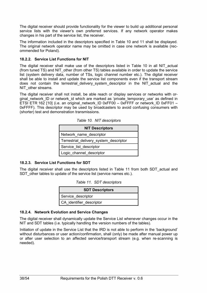
38/54 Requirements for the Polish DTT Receiver v. 0.6
The digital receiver should provide functionality for the viewer to build up additional personal service lists with the viewer’s own preferred services. If any network operator makes changes in his part of the service list, the receiver.
The information included in the descriptors specified in Table 10 and 11 shall be displayed. The original network operator name may be omitted in case one network is available (rec-ommended for Poland).
18.2.2. Service List Functions for NIT
The digital receiver shall make use of the descriptors listed in Table 10 in all NIT_actual (from tuned TS) and NIT_other (from other TS) tables available in order to update the service list (system delivery data, number of TSs, logic channel number etc.). The digital receiver shall be able to install and update the service list components even if the transport stream does not contain the terrestrial_delivery_system_descriptor in the NIT_actual and the NIT_other streams.
The digital receiver shall not install, be able reach or display services or networks with or-ginal_network_ID or network_id which are marked as ‘private_temporary_use’ as defined in ETSI ETR 162 [10] (i.e. an original_network_ID 0xFF00 – 0xFFFF or network_ID 0xFF01 – 0xFFFF). This descriptor may be used by broadcasters to avoid confusing consumers with (shorter) test and demonstration transmissions.
Table 10. NIT descriptors
NIT Descriptors
Network_name_descriptor
Terrestrial_delivery_system_descriptor
Service_list_descriptor
Logic_channel_descriptor
18.2.3. Service List Functions for SDT
The digital receiver shall use the descriptors listed in Table 11 from both SDT_actual and SDT_other tables to update of the service list (service names etc.).
Table 11. SDT descriptors
SDT Descriptors
Service_descriptor
CA_identifier_descriptor
18.2.4. Network Evolution and Service Changes
The digital receiver shall dynamically update the Service List whenever changes occur in the NIT and SDT tables (i.e. typically handling the version numbers of the tables).
Initiation of update in the Service List that the IRD is not able to perform in the ‘background’ without disturbances or user action/confirmation, shall (only) be made after manual power up or after user selection to an affected service/transport stream (e.g. when re-scanning is needed).

Requirements for the Polish DTT Receiver v. 0.6 39/54
18.3. Event Schedule Guide (ESG)
18.3.1. ESG Requirements
The ESG shall include the EIT present/following tables, see ETSI EN 300 468 [16] and should include the EIT schedule.
The digital receiver shall be able to handle situations when the EIT is not present.
The ESG shall be non-discriminatory and display all services on an equal basis.
The ESG shall process and display the relevant content of the following tables (including start-time, end-time/duration and content of all descriptors specified below):
18.3.2. EIT p/f
The digital receiver shall make use of the EIT p/f tables from both EIT_actual and EIT_other tables.
The digital receiver manufacturer shall provide a procedure that allows the user to configure blanking of video and muting of sound for certain parental rating values as well as a protec-tion against settings modification made by unauthorised person.
The receiver shall allow selection from among at least 4 levels of the parental control: up to 7 years, up to 12years, up to 16 years and up to 18 years.
If information is missing (i.e. not included in the transmission) the ESG shall not display an error message, instead the text information field shall stay empty.
Table 12. EIT p/f descriptors
EIT p/f Descriptors
Short_event_descriptor
Extended_event_descriptor
Component_descriptor
Content_descriptor
Parental_rating_descriptor
18.3.3. EIT Schedule
Upon user request for EIT schedule information, the IRD shall look for the reference using linkage descriptor mechanism in the NIT and perform a frequency re-tuning if necessary. Linkage_type 0x04 (“Transport Stream containing complete network/bouquet SI”) shall be used to refer to EIT schedule information.
Table 13. EIT schedule descriptors
EIT Schedule Descriptors
Short_event_descriptor
Component_descriptor
Content_descriptor
Parental_rating_descriptor
CA_identifier_descriptor (option)
40/54 Requirements for the Polish DTT Receiver v. 0.6
18.3.4. TDT and TOT
The ESG shall display correct event times as conveyed by the TDT, adjusted by the offset relayed in the TOT and the country name selected by the user.
Table 14. TOT descriptor
TOT Descriptor
Local_time_offset_descriptor
Note. TDT contains UTC time but no descriptors.
19. SYSTEM SOFTWARE AND API
19.1. Profile 0
The digital receiver of the Profile 0 shall have a system software for interpretation and han-dling of the active service information and control of the local hardware/software.
19.2. Profile 1
The digital receiver of the Profile 1 shall support the API and content formats mandatory for the Enhanced Broadcast Profile, as defined in ETSI TS 102 590 [19] for DVB-MHP 1.2.
19.3. Profile 2
The digital receiver of the Profile 2 shall support the API and contents formats mandatory for the Interactive Broadcast Profile, as defined ETSI TS 102 590 [19] for DVB-MHP 1.2.
20. USER PREFERENCES
20.1. Stored Preferences
The user shall be able to store preferences in non-volatile memory of the digital receiver. The following preferences of the user shall be implemented:
• Video display preferences as specified in section 9.2.
• Audio preferences as specified in section 10.3.4 and 10.3.5.
• Primary and secondary audio language as specified in section 10.3.5.
• Audio delay in S/PDIF output as specified in section 10.3.6.
• Primary and secondary subtitling language as specified in section 11.2.
• Service list as specified in section 18.2.
In addition STB shall store following user preferences related to HDMI output:
• Output video format: automatic or fixed mode, as specified in section 13.3.1.2.
• Output audio format as specified in section 10.3.4.
• HDCP preferences as specified in the subsection 13.3.1.4.
20.2. Deletion of Service List
The receiver shall provide a function to remove all service lists (default and user defined) without affecting other parameters (e.g. user preferences).
20.3. Reset to Factory Settings
The receiver shall provide a function to reset all parameters to factory mode, thus removing all service lists, user preferences, etc. After reset, the IRD shall enter installation state.

Requirements for the Polish DTT Receiver v. 0.6 41/54
21. REQUIREMENTS OF POWER SUPPLY OF DIGITAL RECEIVER The digital receiver shall be adapted to the power supply from the power network of the al-ternating current with following parameters:
• Voltage: 230 V ±10% in compliance with IEC 60038 [40],
• Frequency: 47-53 Hz in compliance with EN 50160 [28].
Construction of the receiver shall assure a minimization of power consumption on each al-lowed operation mode. Manufacturers of receivers are recommended to follow the “Code of Conduct on Energy Efficiency of Digital TV Service Systems” [60] developed by the Euro-pean Commission.
22. SAFETY REQUIREMENTS OF DIGITAL RECEIVER Safety of the digital receiver is defined in EN 60065 [34] for Class II equipment.
23. ELECTROMAGNETIC COMPATIBILITY OF DIGITAL RECEIVER
23.1. Common Requirements
Each digital receiver shall meet requirement of EN 61000-6-1 [36] and EN 61000-6-3 [37].
23.2. Profile 0 and 1 without data interface
Digital receivers of the Profile 0 or 1 without any data interface, i.e. receivers without any in-terface described in sections 13.3.3 and 13.3.4 shall meet requirements of EN 55013 [30] and EN 55020 [31].
23.3. Profile 0 and 1 with data interface or Profile 2
Digital receivers equipped with any interface described in sections 13.3.3 or 13.3.4 shall meet requirements of EN 55022 [32] and EN 55024 [33].

42/54 Requirements for the Polish DTT Receiver v. 0.6

Requirements for the Polish DTT Receiver v. 0.6 43/54
Annex A
1. LIST OF DVB-T CHANNELS IN BAND III OF VHF RANGE
Table 15. List of DVB-T channels in Band III of VHF range
Channel borders Channel number fmin (MHz) fmax (MHz)
fc (MHz)
5 174 181 177,5
6 181 188 184,5
7 188 195 191,5
8 195 202 198,5
9 202 209 205,5
10 209 216 212,5
11 216 223 219,5
12 223 230 226,5
2. LIST OF DVB-T CHANNELS IN BAND IV AND V OF UHF RANGE
Table 16. List of DVB-T channels in Band IV of UHF range
Channel borders Channel number fmin (MHz) fmax (MHz)
fc (MHz)
21 470 478 474
22 478 486 482
23 486 494 490
24 494 502 498
25 502 510 506
26 510 518 514
27 518 526 522
28 526 534 530
29 534 542 538
30 542 550 546
31 550 558 554
32 558 566 562
33 566 574 570
34 574 582 578

44/54 Requirements for the Polish DTT Receiver v. 0.6
Table 17. List of DVB-T channels in Band V of UHF range
Channel borders Channel number fmin (MHz) fmax (MHz)
fc (MHz)
35 582 590 586
36 590 598 594
37 598 606 602
38 606 614 610
39 614 622 618
40 622 630 626
41 630 638 634
42 638 646 642
43 646 654 650
44 654 662 658
45 662 670 666
46 670 678 674
47 678 686 682
48 686 694 690
49 694 702 698
50 702 710 706
51 710 718 714
52 718 726 722
53 726 734 730
54 734 742 738
55 742 750 746
56 750 758 754
57 758 766 762
58 766 774 770
59 774 782 778
60 782 790 786
61 790 798 794
62 798 806 802
63 806 814 810
64 814 822 818
65 822 830 826
66 830 838 834
67 838 846 842
68 846 854 850
69 854 862 858

Requirements for the Polish DTT Receiver v. 0.6 45/54
Annex B
1. REMOTE CONTROL UNIT (RCU)
1.1. General Remarks
Digital receiver of Profile 0 shall be equipped with remote control. Manufacturer will deter-mine its functionality following rules given in ETSI EG 202 116 [2].
Remaining Profiles shall have remote control with properties as specified in section below.
It is recommended to equip the receiver of the Profile 2 with a cordless keyboard.
1.2. Functions
RCU of the interactive receiver shall include at least following functions:
1.2.1. Numeric Pad
1.2.1.1. General Requirements
RCU shall have 10 digit buttons, labelled 0 – 9 in the layout conforming with ITU-T Recom-mendation E.161 [46]. Letters of the alphabet shall be assigned to buttons in compliance with ETSI ETS 300 640 [12].
The example-solution of the numeric pad is shown on Figure 2.
Figure 2. Block of numeric pad
1.2.1.2. Text Entry
The numeric pad shall enable to enter any text using all the Polish character set. It is made by multiple tapping of suitable buttons until the intentional effect is got. Table 18 shows rec-ommended assignment and sequences of characters for each button based on ETSI ES 202 130 [9]. The character set assigned to the “1” button should be considered as a minimum.
1 .,;@
2 abc
3 def
4 ghi
5 jkl
6 mno
0
7 pqrs
8 tuv
9 wxyz

46/54 Requirements for the Polish DTT Receiver v. 0.6
Table 18. Sequence of characters assigned to numeric pad
Key Character sequence
. , ; @ 1 ? ! : ” % ( ) + - / * & ' = < > #
a b c 2 ą ć A B C Ą Ć
d e f 3 ę D E F Ę
g h i 4 G H I
j k l 5 ł J K L Ł
m n o 6 ń ó M N O Ń Ó
p q r s 7 ś P Q R S Ś
t u v 8 T U V
w x y z 9 ź Ŝ W X Y Z Ź ś
0 „space” „new line”
1.2.2. TV Pad
RCU should have following buttons for the basic TV reception functionality. If present, they shall have following functions:
• Power On/Off – turns the receiver on and off;
• Mute – muting the sound volume;
• Programme Up/Down – switching programs one up or down (Pr+, Pr-);
• Volume Up/Down – adjusting volume output level (Vol+, Vol-);
• TV/Radio – function that puts the receiver directly into conventional television mode, i.e. only audio, video and subtitling or sound programme;
• Text – function allowing to display teletext defined in section 12.1, if present;
• Menu – function that activates displaying setting menu of the receiver.
The example-solution of the TV pad is shown on Figure 3.
0
9 wxyz
8 tuv
7 pqrs
6 mno
5 jkl
4 ghi
1 ,.;@
3 def
2 abc

Requirements for the Polish DTT Receiver v. 0.6 47/54
Figure 3. Block of TV pad
1.2.3. Interactive Pad
RCU shall have following buttons for navigation on receiver interface and MHP applications. Buttons shall realize following functions:
• Navigation or pointing system for navigation on the OSD layer (Arrows: Up/Down, Right/Left);
• OK – function that selects or conforms current choice or statement;
• Back – function that returns to the previous state of the receiver or menu level;
• Exit –function of exit to the menu top level or the basic state;
• Multifunctional buttons – 4 colour-coded buttons placed horizontally in the following order, starting from left: red (R), green (G), yellow (Y) and blue (B) for functions not assigned in advance.
The example-solution of the interactive pad is shown on Figure 4.
Figure 4. Block of interactive pad
1.2.4. Navigation Pad
RCU should have following buttons for basic Navigator functionality. If are present, then shall realize following functions:
Mute
TV/ Radio
+
Vol -
+
Pr -
Menu
Text
R G Y B
OK
Back Exit
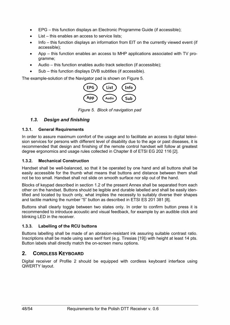
48/54 Requirements for the Polish DTT Receiver v. 0.6
• EPG – this function displays an Electronic Programme Guide (if accessible);
• List – this enables an access to service lists;
• Info – this function displays an information from EIT on the currently viewed event (if accessible);
• App – this function enables an access to MHP applications associated with TV pro-gramme;
• Audio – this function enables audio track selection (if accessible);
• Sub – this function displays DVB subtitles (if accessible).
The example-solution of the Navigator pad is shown on Figure 5.
Figure 5. Block of navigation pad
1.3. Design and finishing
1.3.1. General Requirements
In order to assure maximum comfort of the usage and to facilitate an access to digital televi-sion services for persons with different level of disability due to the age or past diseases, it is recommended that design and finishing of the remote control handset will follow at greatest degree ergonomics and usage rules collected in Chapter 8 of ETSI EG 202 116 [2].
1.3.2. Mechanical Construction
Handset shall be well-balanced, so that it be operated by one hand and all buttons shall be easily accessible for the thumb what means that buttons and distance between them shall not be too small. Handset shall not slide on smooth surface nor slip out of the hand.
Blocks of keypad described in section 1.2 of the present Annex shall be separated from each other on the handset. Buttons should be legible and durable labelled and shall be easily iden-tified and located by touch only, what implies the necessity to suitably diverse their shapes and tactile marking the number “5” button as described in ETSI ES 201 381 [8].
Buttons shall clearly toggle between two states only. In order to confirm button press it is recommended to introduce acoustic and visual feedback, for example by an audible click and blinking LED in the receiver.
1.3.3. Labelling of the RCU buttons
Buttons labelling shall be made of an abrasion-resistant ink assuring suitable contrast ratio. Inscriptions shall be made using sans serif font (e.g. Tiresias [19]) with height at least 14 pts. Button labels shall directly match the on-screen menu options.
2. CORDLESS KEYBOARD Digital receiver of Profile 2 should be equipped with cordless keyboard interface using QWERTY layout.
Info List EPG
Sub Audio App

Requirements for the Polish DTT Receiver v. 0.6 49/54
Annex C
1. COMPARISON OF PROFILES OF DIGITAL RECEIVERS FOR POLAND
1.1. Introduction
This Annex gives a comparison of requirements for each profile of the digital receiver (IRD) defined in the par. 4.4 of the present specification. Table 19 lists all chapters and sections containing the requirements pointing in the same time how to apply them towards each pro-file as well as towards STB and iDTV.
1.2. Description of Columns of Table 19
Profiles are described in section 6.1 as:
• Profile 0 which refers simple receiver of TV signals (zapper);
• Profile 1 which refers locally interactive receiver (without return channel);
• Profile 2 which refers a bidirectionally interactive receiver (with return channel).
Symbols placed in each cell of Table 19 means:
-: requirement does not refer the indicated receiver version,
x: requirement is mandatory for the indicated receiver version,
o: requirement is optional for the indicated receiver version.
It should be noted that above symbols refers to all chapters or sections of the present docu-ment. Actual requirements can only be found in relevant part of the document.
Table 19. Comparison of requirements of digital receiver
Profile 0 Profile 1 Profile 2 Chapter/Section
STB iDTV STB iDTV STB iDTV
6. General Characteristics of the Digital Receiver - - - - - -
6.1. Introduction - - - - - -
6.2. Receiving Capabilities x x x x x x
6.3. Scanning Procedure x x x x x x
6.4. Access to Services x x x x x x
6.5. Navigator SI x x x x x x
6.6..Auto Installation x x x x x x
6.7. Conditional Access (option) o o o o o o
6.8. Parental Access Control x x x x x x
6.9. Video Decoder x x x x x x
6.10. Audio Decoder x x x x x x
6.11. Teletext and DVB Subtitles - - - - - -
6.11.1. Teletext x1 x1 x1 x1 x1 x1
6.11.2. DVB Subtitles x x x x x x
6.12. API - - x x x x

50/54 Requirements for the Polish DTT Receiver v. 0.6
Profile 0 Profile 1 Profile 2 Chapter/Section
STB iDTV STB iDTV STB iDTV
6.13. Return Channel - - - - x x
6.14. System Software Update x x x x x x
6.15. Power Supply Requirements x x x x x x
7. RF Tuner and Demodulator of the Digital De-coder - - - - - -
7.1. Scanning Procedure x x x x x x
7.2. Quality Reception Detector x x x x x x
7.3. Parameters of RF tuner and demodulator - - - - - -
7.3.1. General Information x x x x x x
7.3.2. Frequencies and Channels Bandwidths x x x x x x
7.3.3. DVB-T Modes x x x x x x
7.3.4. RF Input Connector x x x x x x
7.3.5. Failure Point Criteria x x x x x x
7.3.6. C/N Performance x x x x x x
7.3.7. Minimum Signal Input levels (sensitivity) x x x x x x
7.3.8. Maximum Input Signal Levels x x x x x x
7.3.9. Immunity to Analogue and/or Digital Signals in Other Channels
x x x x x x
7.3.10. Immunity to Co-channel Interference from Analogue TV Signals
x x x x x x
7.3.11. Guard Interval Utilization in Single Fre-quency Networks
x x x x x x
7.3.12. MFN Multipath Performance x x x x x x
7.3.12.1. Performance with Long Echoes x x x x x x
7.3.12.2. Performance with Short Echoes x x x x x x
8. MPEG-2Demultiplexer - - - - - -
8.1. General Requirements x x x x x x
8.2. Constraints and Extensions x x x x x x
8.3. DVB Descrambler Performance x x x x x x
8.4. System Clock Recovery x x x x x x
9. Video Decoder - - - - - -
9.1. Basic Requirements x x x x x x
9.2. Constraints and Extensions - - - - - -
9.2.1. Active Format Descriptor x x x x x x
9.2.2. Luminance Resolution x x x x x x
9.2.3. Display Mode for 16:9 Material on 4:3 Monitors
x x x x x x
9.2.4. Displaying 4:3 Material on 16:9 Monitors x x x x x x
9.2.5. 16:9-letterbox Conversion x x x x x x
9.2.6. Down-conversion - - x x x x
9.2.7. Up-conversion x x x x x x

Requirements for the Polish DTT Receiver v. 0.6 51/54
Profile 0 Profile 1 Profile 2 Chapter/Section
STB iDTV STB iDTV STB iDTV
9.2.8. Default Location Mode x x x x x x
9.2.9. Still Pictures Support x x x x x x
9.2.10. Video Minimum Bitrate x x x x x x
9.2.11. HDMI Video Output and HD Display x x x x x x
9.2.12. Analogue Video Output x o x o x o
10. Audio Decoder - - - - - -
10.1. Basic Requirements x x x x x x
10.2. Scope of Requirements x x x x x x
10.3. Constraints and Extensions - - - - - -
10.3.1. Audio/Video Synchronization x x x x x x
10.3.2. Audio Metadata x x x x x x
10.3.3. Analogue Audio Output x x x x x x
10.3.4. Digital Audio Output - - - - - -
10.3.4.1. HDMI (STB only) x - x - x -
10.3.4.2. S/PDIF x3 x3 x3 x3 x3 x3
10.3.4.3. Audio Prioritising x x x x x x
10.3.5. Audio Handling when Changing Audio Streams
x x x x x x
10.3.6. Adjustment of Video/Audio Delay x x x x x x
10.3.7. Audio Handling when Changing Ser-vice or Audio Format
x x x x x x
10.3.8. IRD Internal Reference Level x x x x x x
11. Teletext and DVB Subtitles - - - - - -
11.1. Teletext x1 x1 x1 x1 x1 x1
11.2. DVB Subtitles x x x x x x
12. Graphics Processor - - - - - -
12.1. Profile 0 x x - - - -
12.2. Profile 1 i 2 - - x x x x
13. Interfaces and Signal Levels of the Receiver - - - - - -
13.1. Introduction - - - - - -
13.2. Analogue TV Reception (option) o o o o o o
13.2.1. RF Loop-through o - o - o -
13.2.2. Output of Composite D1/PAL TV-signal o - o - o -
13.3. Digital Interfaces - - - - - -
13.3.1. HDMI Interface - - - - - -
13.3.1.1. General Requirements x - x - x -
13.3.1.2. Video Output x - x - x -
13.3.1.3. Audio Output x - x - x -
13.3.1.4. HD Signal Protection x - x - x -
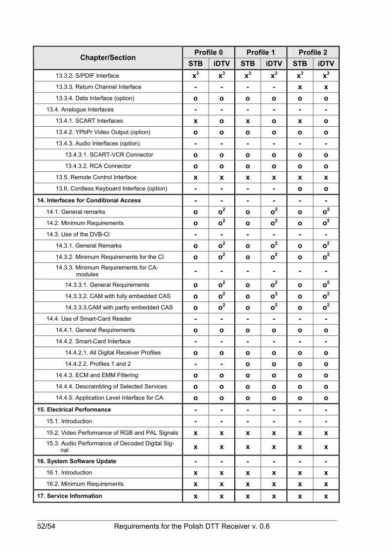
52/54 Requirements for the Polish DTT Receiver v. 0.6
Profile 0 Profile 1 Profile 2 Chapter/Section
STB iDTV STB iDTV STB iDTV
13.3.2. S/PDIF Interface x3 x3 x3 x3 x3 x3
13.3.3. Return Channel Interface - - - - x x
13.3.4. Data Interface (option) o o o o o o
13.4. Analogue Interfaces - - - - - -
13.4.1. SCART Interfaces x o x o x o
13.4.2. YPbPr Video Output (option) o o o o o o
13.4.3. Audio Interfaces (option) - - - - - -
13.4.3.1. SCART-VCR Connector o o o o o o
13.4.3.2. RCA Connector o o o o o o
13.5. Remote Control Interface x x x x x x
13.6. Cordless Keyboard Interface (option) - - - - o o
14. Interfaces for Conditional Access - - - - - -
14.1. General remarks o o2 o o2 o o2
14.2. Minimum Requirements o o2 o o2 o o2
14.3. Use of the DVB-CI - - - - - -
14.3.1. General Remarks o o2 o o2 o o2
14.3.2. Minimum Requirements for the CI o o2 o o2 o o2
14.3.3. Minimum Requirements for CA-modules
- - - - - -
14.3.3.1. General Requirements o o2 o o2 o o2
14.3.3.2. CAM with fully embedded CAS o o2 o o2 o o2
14.3.3.3.CAM with partly embedded CAS o o2 o o2 o o2
14.4. Use of Smart-Card Reader - - - - - -
14.4.1. General Requirements o o o o o o
14.4.2. Smart-Card Interface - - - - - -
14.4.2.1. All Digital Receiver Profiles o o o o o o
14.4.2.2. Profiles 1 and 2 - - o o o o
14.4.3. ECM and EMM Filtering o o o o o o
14.4.4. Descrambling of Selected Services o o o o o o
14.4.5. Application Level Interface for CA o o o o o o
15. Electrical Performance - - - - - -
15.1. Introduction - - - - - -
15.2. Video Performance of RGB and PAL Signals x x x x x x
15.3. Audio Performance of Decoded Digital Sig-nal
x x x x x x
16. System Software Update - - - - - -
16.1. Introduction x x x x x x
16.2. Minimum Requirements x x x x x x
17. Service Information x x x x x x

Requirements for the Polish DTT Receiver v. 0.6 53/54
Profile 0 Profile 1 Profile 2 Chapter/Section
STB iDTV STB iDTV STB iDTV
18 Navigator - - - - - -
18.1. General Requirements x x x x x x
18.2. Service List - - - - - -
18.2.1. Service List Requirements x x x x x x
18.2.2. Service List Functions for NIT x x x x x x
18.2.3. Service List Functions for SDT x x x x x x
18.2.4. Network Evolution and Service Changes
x x x x x x
18.3. Event Schedule Guide (ESG) - - - - - -
18.3.1. ESG Requirements x x x x x x
18.3.2. EIT p/f x x x x x x
18.3.3. EIT Schedule x x x x x x
18.3.4. TDT and TOT x x x x x x
19. System Software and API - - - - - -
19.1. Profile 0 x x - - - -
19.2. Profile 1 - - x x - -
19.3. Profile 2 - - - - x x
20. User Preferences - - - - - -
20.1. Stored Preferences x x x x x x
20.2. Deletion of Service List x x x x x x
20.3. Reset to Factory Settings x x x x x x
21. Requirements of Power Supply of Digital Re-ceiver x x x x x x
22. Safety Requirements of Digital Receiver x x x x x x
23. Electromagnetic Compatibility of Digital Re-ceiver - - - - - -
23.1. Common Requirements x x x x x x
23.2. Profile 0 and 1 without data interface x x x x - -
23.3. Profile 0 and 1 with data interface or Profile 2
x x x x x x
Annex A - - - - - - 1. List of DVB-T Channels in Band III of VHF
Range x x x x x x
2. List of DVB-T Channels in Band IV and V of UHF Range x x x x x x
Annex B - - - - - -
1. Remote Control Unit (RCU) - - - - - -
1.1. General Remarks x x - - - -
1.2. Functions - - x x x x
1.2.1. Numeric Pad - - x x x x
1.2.1.1. General Requirements - - x x x x

54/54 Requirements for the Polish DTT Receiver v. 0.6
Profile 0 Profile 1 Profile 2 Chapter/Section
STB iDTV STB iDTV STB iDTV
1.2.1.2. Text Entry - - x x x x
1.2.2. TV Pad - - x x x x
1.2.3. Interactive Pad - - x x x x
1.2.4. Navigation Pad - - x x x x
1.3. Design and finishing - - x x x x
1.3.1. General Requirements - - x x x x
1.3.2. Mechanical Construction - - x x x x
1.3.3. Labelling of the RCU buttons - - x x x x
2. Cordless Keyboard o o o o o o
Note 1: The first possibility of teletext decoding refers to STB and iDTV and second only to STB.
Note 2: At least one CI-socked is mandatory for iDTV with diagonal of the screen at least 30 cm.
Note 3: It does not refer the digital receiver with at least 5 analogue outputs for surround sound.