report documentation page form approved ... of auxiliary brake systems in heavy trucks, regenerative...
TRANSCRIPT
Standard Form 298 (Rev. 8-98) Prescribed by ANSI Std. Z39-18
REPORT DOCUMENTATION PAGE Form Approved OMB No. 0704-0188
The public reporting burden for this collection of information is estimated to average 1 hour per response, including the time for reviewing instructions, searching existing data sources, gathering and maintaining the data needed, and completing and reviewing the collection of information. Send comments regarding this burden estimate or any other aspect of this collection of information, including suggestions for reducing this burden, to Department of Defense, Washington Headquarters Services, Directorate for information on Operations and Reports (0704-0188), 1215 Jefferson Davis Highway, Suite 1204, Arlington, VA 22202-4302. Respondents should be aware that notwithstanding any other provision of law, no person shall be subject to any penalty for failing to comply with a collection of information if it does not display a currently valid OMB control number. PLEASE DO NOT RETURN YOUR FORM TO THE ABOVE ADDRESS.
1. REPORT DATE (DD-MM-YYYY) 20-05-2008
2. REPORT TYPE Final
3. DATES COVERED (From - To)
5a. CONTRACT NUMBER
5b. GRANT NUMBER
4. TITLE AND SUBTITLE Test Operations Procedure (TOP) 2-2-608 Braking, Wheeled Vehicles
5c. PROGRAM ELEMENT NUMBER
5d. PROJECT NUMBER
5e. TASK NUMBER
6. AUTHORS
5f. WORK UNIT NUMBER
7. PERFORMING ORGANIZATION NAME(S) AND ADDRESS(ES) Automotive Test Division (TEDT-AT-AD-I) US Army Aberdeen Test Center 400 Colleran Road Aberdeen Proving Ground, MD 21005-5059
8. PERFORMING ORGANIZATION REPORT NUMBER TOP 2-2-608
10. SPONSOR/MONITOR’S ACRONYM(S)
9. SPONSORING/MONITORING AGENCY NAME(S) AND ADDRESS(ES) Test Business Management Division (TEDT-TMB) US Army Developmental Test Command 314 Longs Corner Road Aberdeen Proving Ground, MD 21005-5055
11. SPONSOR/MONITOR’S REPORT NUMBER(S) Same as item 8
12. DISTRIBUTION/AVAILABILITY STATEMENT Approved for public release; distribution unlimited.
13. SUPPLEMENTARY NOTES Defense Technical Information Center (DTIC), AD No.: This TOP supersedes TOP 2-2-608, dated 29 October 1987. 14. ABSTRACT This TOP provides standardized tests for evaluating wheeled vehicle braking systems. Because it is associated with personnel safety, thorough testing and evaluation of a vehicle's braking capability is required to assure dependability and effectiveness under a variety of conditions. Major factors to be considered in the evaluation of vehicle braking systems are stopping and grade holding ability, vehicle stability and control during brake applications, and individual braking component endurance under various operational conditions. The use of advanced technologies in brake system design will dictate the test design necessary to ensure the system is safe and effective. Some of these technologies include the use of auxiliary brake systems in heavy trucks, regenerative braking in hybrid vehicles, antilock braking systems, and electronic stability control brake systems. Requirements and procedures for brake system testing are contained in documents such as the Federal Motor Vehicle Safety Standards and the Society of Automotive Engineers procedures. This TOP identifies procedures and requirements for vehicles designed for military operations. 15. SUBJECT TERMS Brake burnish Brake balance Brake effectiveness Maximum pedal effort Deceleration rate Roller dynamometer Auxiliary braking devices Regenerative braking Mountain highway brake test Brake fade Trailer compatibility Peak friction coefficient (skid number) 16. SECURITY CLASSIFICATION OF:
a. REPORT B. ABSTRACT C. THIS PAGE
19a. NAME OF RESPONSIBLE PERSON
Unclassified Unclassified Unclassified
17. LIMITATION OF ABSTRACT SAR
18. NUMBER OF PAGES
60 19b. TELEPHONE NUMBER (include area code)

US ARMY DEVELOPMENTAL TEST COMMAND TEST OPERATIONS PROCEDURE
*Test Operations Procedure 2-2-608 20 May 2008 DTIC AD No.
BRAKING, WHEELED VEHICLES Page Paragraph 1. SCOPE ............................................................................................. 2 1.1 Purpose............................................................................................. 2 1.2 Limitations ....................................................................................... 2 2. FACILITIES AND INSTRUMENTATION ................................... 3 2.1 Facilities and Test Courses .............................................................. 3 2.2 Test Instrumentation ........................................................................ 4 2.3 Specialized Equipment/Facilities .................................................... 5 3. REQUIRED TEST CONDITIONS ................................................. 6 3.1 Preparation for Test.......................................................................... 6 3.2 Test Controls.................................................................................... 6 3.3 Restrictions ...................................................................................... 7 4. TEST PROCEDURES..................................................................... 7 4.1 Brake System Inspection/Characterization ...................................... 7 4.2 Safety/Performance Evaluation ....................................................... 8 4.3 Endurance/Durability Testing.......................................................... 12 5. DATA REQUIRED ......................................................................... 14 5.1 Brake System Inspection/Characterization ...................................... 14 5.2 Safety / Performance Evaluation ..................................................... 15 5.3 Endurance /Durability Testing......................................................... 19 6. PRESENTATION OF DATA ......................................................... 20 6.1 Brake System Inspection/Characterization ...................................... 20 6.2 Safety/Performance Evaluation ....................................................... 20 6.3 Endurance/Durability Testing.......................................................... 21 APPENDIX A. MOUNTAIN HIGHWAY BRAKE TEST OUTLINE ...................... A-1 B. BRAKE BURNISH PROCEDURE .................................................. B-1 C. BRAKE DATA SHEETS .................................................................. C-1 D. REFERENCES APPENDIX............................................................... D-1 *This TOP supersedes TOP 2-2-608, dated 29 October 1987.
Approved for public release; distribution unlimited.

TOP 2-2-608 20 May 2008
2
1. SCOPE. This Test Operations Procedure (TOP) provides standardized tests for evaluating wheeled vehicle braking systems. 1.1 Purpose. Braking is a basic element of automotive testing and, because of its association with personnel safety, dictates the requirement for particularly thorough testing and evaluation of wheeled vehicle braking systems to assure dependability and effectiveness under all conditions. Major factors considered in the evaluation of wheeled vehicle braking systems are stopping and grade holding ability, vehicle stability and control when applying brakes, and individual braking system component endurance under various operational conditions. The use of advanced technologies in the design of vehicle braking systems will dictate the test design necessary to ensure that the system is safe and effective. Some of these technologies include the use of auxiliary brake systems in heavy trucks including various power train retarding systems (e.g. engine braking, transmission braking), regenerative braking in hybrid vehicles, antilock brake systems (ABS), and electronic stability control (ESC) brake systems. Brake testing involves not only tests on straight, level roads but tests on mountain highways that have long grades requiring many brake applications. Brake test evaluation also includes brake recovery capability following water immersion of the vehicle brakes in a fording basin. Requirements and procedures for brake systems testing are contained in documents such as the Federal Motor Vehicle Safety Standards (FMVSS) and the various Society of Automotive Engineers (SAE) procedures. This test procedure identifies pertinent procedures and requirements useful for testing vehicles designed for military operations. 1.2 Limitations. This TOP describes tests to assess wheeled vehicle braking systems for compliance with applicable standards and to assess their operational capabilities. This TOP applies to wheeled vehicles designed for highway operation. These procedures may be used for both developmental and production tests. Vehicles designed specifically for off-highway operation that do not possess a maximum vehicle speed capability of at least 64 km/hr will be considered on an individual basis. Specific test parameters and criteria will be provided in plans of test prepared for each particular vehicle design.

TOP 2-2-608 20 May 2008
3
2. FACILITIES AND INSTRUMENTATION. 2.1 Facilities and Test Courses.
Item Requirements Level Paved Road A straight, level, paved road with a lane width
of not less than 3.7 m, a longitudinal gradient ≤ 1%, and a side-to-side gradient ≤ 2%. Length of the roadway should be sufficient to allow the test vehicle, at its required payload condition, to accelerate to 96 km/hr (or maximum speed if lower than 96 km/hr) and then safely stop.
Longitudinal Grades Longitudinal slopes ranging from 5 to 60 percent grade and of sufficient length to accommodate vehicles of various dimensions.
Fording Basin A water basin of sufficient length and depth to completely submerge the service brake assemblies of all sizes of wheeled vehicles.
Mountain Highway Course Reference Appendix A. Downhill Roadway A roadway ranging from 9 to 11 percent grade
for a distance of approximately 2 miles with a reasonably level surface at the bottom of the grade of sufficient length to permit a 64 km/hr brake stop.
Road Surfaces of Various Friction Levels
SAE J461** describes the split friction surface, the changing friction surface, and the lane change test surface.
Curved Roadway Low friction, 500 -ft. radius curved roadway as described in paragraph 12 of SAE J16262.
Hilly Course, Paved Paved course with grades of less than 11% that allow moderate to high road speeds; e.g., Harford Loop roadway at Aberdeen Test Center (ATC) and the Mountain Test Course (reference Appendix A).
Hilly Course, Off-road Cross-country; moderate to rough native soil and stone with grades less than 30%; e.g., Churchville Test Area (CTA) course B. Secondary; improved gravel road with grades less than 10%; e.g., CTA course C and Munson Test Area (MTA) gravel course.
** Superscript numbers correspond to those in Appendix D, References.
TOP 2-2-608 20 May 2008
4
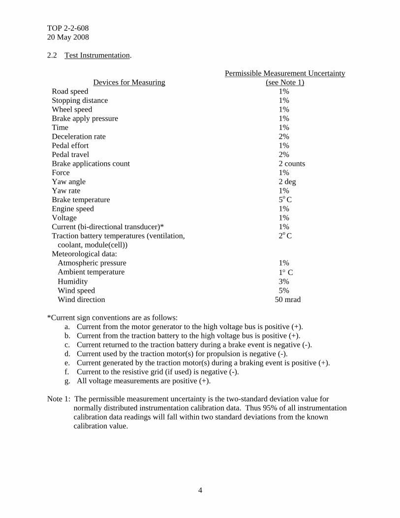
2.2 Test Instrumentation.
Devices for Measuring Permissible Measurement Uncertainty
(see Note 1) Road speed 1% Stopping distance 1% Wheel speed 1% Brake apply pressure 1% Time 1% Deceleration rate 2% Pedal effort 1% Pedal travel 2% Brake applications count 2 counts Force 1% Yaw angle 2 deg Yaw rate 1% Brake temperature 5o C Engine speed 1% Voltage 1% Current (bi-directional transducer)* 1% Traction battery temperatures (ventilation, coolant, module(cell))
2o C
Meteorological data: Atmospheric pressure 1% Ambient temperature 1° C Humidity 3% Wind speed 5% Wind direction 50 mrad
*Current sign conventions are as follows: a. Current from the motor generator to the high voltage bus is positive (+). b. Current from the traction battery to the high voltage bus is positive (+). c. Current returned to the traction battery during a brake event is negative (-). d. Current used by the traction motor(s) for propulsion is negative (-). e. Current generated by the traction motor(s) during a braking event is positive (+). f. Current to the resistive grid (if used) is negative (-). g. All voltage measurements are positive (+). Note 1: The permissible measurement uncertainty is the two-standard deviation value for normally distributed instrumentation calibration data. Thus 95% of all instrumentation calibration data readings will fall within two standard deviations from the known calibration value.
TOP 2-2-608 20 May 2008
5
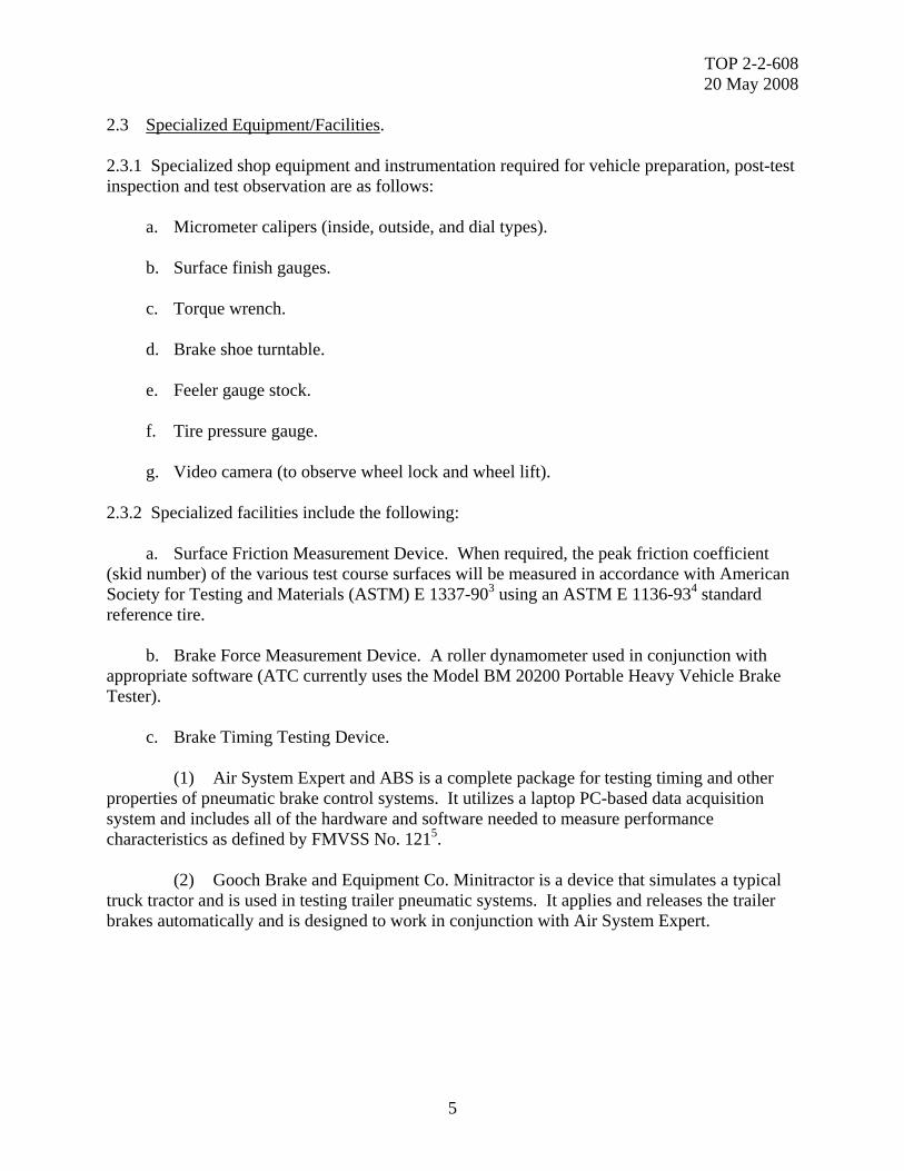
2.3 Specialized Equipment/Facilities. 2.3.1 Specialized shop equipment and instrumentation required for vehicle preparation, post-test inspection and test observation are as follows: a. Micrometer calipers (inside, outside, and dial types). b. Surface finish gauges. c. Torque wrench. d. Brake shoe turntable. e. Feeler gauge stock. f. Tire pressure gauge. g. Video camera (to observe wheel lock and wheel lift). 2.3.2 Specialized facilities include the following: a. Surface Friction Measurement Device. When required, the peak friction coefficient (skid number) of the various test course surfaces will be measured in accordance with American Society for Testing and Materials (ASTM) E 1337-903 using an ASTM E 1136-934 standard reference tire. b. Brake Force Measurement Device. A roller dynamometer used in conjunction with appropriate software (ATC currently uses the Model BM 20200 Portable Heavy Vehicle Brake Tester). c. Brake Timing Testing Device. (1) Air System Expert and ABS is a complete package for testing timing and other properties of pneumatic brake control systems. It utilizes a laptop PC-based data acquisition system and includes all of the hardware and software needed to measure performance characteristics as defined by FMVSS No. 1215. (2) Gooch Brake and Equipment Co. Minitractor is a device that simulates a typical truck tractor and is used in testing trailer pneumatic systems. It applies and releases the trailer brakes automatically and is designed to work in conjunction with Air System Expert.
TOP 2-2-608 20 May 2008
6
3. REQUIRED TEST CONDITIONS. 3.1 Preparation for Test. a. Review all instructional material issued with the test vehicles by the manufacturer, contractor, or government, as well as reports of previous similar tests on the same types of vehicles. b. Select the applicable test procedures to be used based on the requirements documents and purpose of the test. Obtain copies of and review the applicable FMVSS and SAE test procedures. These procedures can be listed in the detailed test plan. c. Prepare data collection sheets to record all pre-test information, conditions of test, test results, observations, and measurements that would be valuable in analysis and assessment. d. Ensure that all test personnel are familiar with the required technical and operational characteristics of the item and with the required test procedures. 3.2 Test Controls. a. Prior to testing ensure that: (1) The vehicle has been prepared and equipped in accordance with standard use and/or within the specifications presented in the test plan. (2) The vehicle is payloaded in accordance with the test plan. (3) The vehicle has received the proper break-in operation. (4) The braking system components are either in good serviceable condition or new, if required. (5) If vehicle stability is a concern, rollover protection and/or tractor/trailer articulation restraints must be considered. (6) The peak friction coefficient (skid number) of each test track must meet the requirements of the procedural documents for both dry and wet road surfaces. The skid number will be determined in accordance with ASTM E 1337-90. (7) Initial brake temperature means the average temperature of the surface brakes on the hottest axle of the vehicle 0.3km before any brake application. Final brake temperature is the average temperature of the service brakes on the hottest axle of the vehicle as soon as the vehicle is stopped and while the brake is applied. (8) Automatic adjusters must remain activated for the duration of the test.
TOP 2-2-608 20 May 2008
7
(9) Brakes shall be adjusted, per the vehicle manufacturer’s recommended procedure, at the beginning of the test. They may only be re-adjusted where specifically indicated in the test procedure. 3.3 Restrictions. Tests are not conducted at night, during inclement weather, in congested traffic, or when the road surface may introduce a hazard to the test vehicle or other traffic on the road. Dry, un-obstructed surfaces are used unless the test plan introduces a specific requirement. Local safety and operational procedures will be carefully followed. Desirable environmental conditions for test conduct are as follows: a. Wind speed: ≤ 3 m/s average value b. Ambient temperature: 0 ≤ T ≤ 30 °C c. Humidity: ≤ 95% 4. TEST PROCEDURES. 4.1 Brake System Inspection/Characterization. 4.1.1 Basic Measurements/Condition. Specific test and vehicle identification characteristics and basic measurements and condition of components of the vehicle brake system should be recorded. SAE J1626 provides recommended vehicle and brake characteristics to include type, make, size, lining material, etc. Recommended brake inspection procedures and acceptance criteria for trucks equipped with hydraulic or air brakes are provided in American Association of Motor Vehicle Administrators6. 4.1.2 Brake Pneumatic Timing (Air and Air Over Hydraulic Brake Systems Only). Brake timing characterizes how fast brakes can be applied and released. Testing is conducted in accordance with FMVSS No. 121. The brake actuation and release times are determined by instrumenting the brake system with pressure transducers mounted at the brake chambers and the service glad hand. The brake apply and release times are measured with the Air System Expert test apparatus. A minimum of six brake applications should be conducted during testing and the results from each application are averaged. If a specific criterion is not presented in the test plan, the requirements of FMVSS No. 121, paragraphs S5.3.3 and S5.3.4, apply. 4.1.3 Brake Balance. Determination of a vehicle’s brake balance is a method of assessing the condition of its brake system prior to the initiation of brake testing. Determining the brake balance of a vehicle is accomplished by measuring the brake force distribution to individual wheels at various input pressures.

TOP 2-2-608 20 May 2008
8
4.1.4 Brake Force Distribution and Threshold Pressures. Brake force distribution and threshold pressure characteristics are determined in a shop setting by means of a Portable Heavy Vehicle Brake Tester as described in paragraph 2.3. In lieu of a brake tester, SAE J1505 and J18547 provide road test procedures and requirements for determination of a vehicle’s brake force distribution and threshold pressures. 4.1.5 Pedal Effort Characteristics. The brake pedal force versus brake apply pressure characteristics are determined by instrumenting the system to measure brake pedal apply force and the resultant brake system apply pressures. Pedal effort force is measured by means of a calibrated load cell (mounted on the brake pedal) and read-out system. The driver should apply a constant brake pressure at which time the pedal effort and resultant brake system pressures are recorded. The pedal effort should be determined at various pressure increments up to the vehicle's maximum hydraulic pressure or governed air pressure. After completion of these tests, the pedal-mounted load cell should be removed to preclude interference with normal driving operations. The criterion for pedal effort is that vehicle stopping ability be in accordance with the appropriate test document (i.e., FMVSS No. 121, FMVSS No. 1058, etc.) at a pedal force designated in the test plan for each specific vehicle test program. In the absence of specific criteria, a maximum pedal force of 800 N will be used per MIL-STD-1472F9. 4.2 Safety/Performance Evaluation. 4.2.1 Brake Burnish. Friction material burnishing is accomplished by utilizing the procedure described in the test plan designated requirements document, i.e.: a. FMVSS 121, paragraph 6.1.8 (air brakes). b. FMVSS 105, paragraphs 7.4.1 and 7.4.2 (hydraulic brakes) c. SAE J46/J253610, paragraph 7. d. Mountain Brake burnish procedure (Appendix B). No brake burnish criterion is presented for the FMVSS and SAE test procedures. However, the criterion for friction material burnishing for the brake burnish procedure presented in Appendix B is that not less than 80 percent of the friction material surface area be in contact with the swept area of the rotating brake member (drum or disk).
TOP 2-2-608 20 May 2008
9
4.2.2 Grade Holding Ability. The vehicle is parked on dry, paved, longitudinal slopes in both ascending and descending attitudes. Service and parking brake systems are engaged separately to assure their individual capability to hold the vehicle stationary. When testing a trailer or semi-trailer a safe disconnect (mechanical, electrical, pneumatic, and hydraulic connections) from the prime mover is maintained. Apply the service or parking brake(s) in accordance with the manufacturer’s recommendation. The test sequence should as a minimum be as follows: a. Position the vehicle on the designated slope. b. Apply the service/parking brake(s). c. Disengage the transmission. d. If testing parking brake, release the service brake. e. Stop the engine. f. Wait a minimum of five minutes. g. Observe vehicle and/or wheel movement. The criterion for grade holding ability for both service and parking brake systems of wheeled vehicles is that each system, independent of the other, hold the vehicle stationary in both ascending and descending attitudes on the maximum longitudinal slope over which the vehicle is required to operate. To determine the longitudinal grade parking brake performance of trucks, trailers, and buses intended for highway use only, the test procedures and requirements presented in SAE J36011, J145212, and J29313 can be utilized. 4.2.3 Brake Effectiveness. Brake stopping distances are obtained from 32 and 64 km/hr and from additional road speeds if specifically requested. Stopping distances are measured over the input pressure range up to the point of wheel locking. Brake drum temperatures should not exceed 121° C, or as otherwise specified, during these tests. These tests will be conducted on a level, hard-surfaced roadway (with proper skid number) with the vehicle at curb weight and at its rated payload condition. The criteria for brake stopping ability are as follows: a. Wheeled vehicles of gross vehicle weight up to and including 22680 kg will be capable of making a straight line full stop from a road speed of 32 km/hr within a distance of 9.1 m; they will be capable of making a full stop from a vehicle speed of not less than 64 km/hr at an average deceleration rate of 4.4 m/s2.
TOP 2-2-608 20 May 2008
10
b. Wheeled vehicles of gross vehicle weight exceeding 22680 kg will be capable of making a straight line full stop from a road speed of 32 km/hr within a distance of 12.2 m; they will be capable of making a full stop from a vehicle speed of not less than 64 km/hr at an average deceleration rate of 3.4 m/s2. c. During all brake stops, vehicle slew shall not exceed the limits of a roadway lane width equal to 1-1/2 times the overall width of the test vehicle. For vehicles equipped with an air brake system the procedures and requirements of FMVSS 121, paragraph 5.3.1 will apply. For vehicles equipped with a hydraulic brake system, the procedures and requirements FMVSS 105, paragraph 5.1.1 will apply. Vehicles and vehicle combinations operating on a public highway must be capable of the brake performance described in FMCSR 393.5214. 4.2.4 Brake Recovery after Water Immersion. Wheeled vehicle braking systems will be completely submerged in water for a period of 15 to 30 minutes. After immersion, recovery is determined by making brake applications from a road speed of 32 km/hr at a pre-selected input pressure at 1-minute intervals. Results will be compared to the dry brake performance previously established for the vehicle. The criterion for brake recovery is that after immersion in water for a period of 15 to 30 minutes, brake stopping ability shall have achieved complete recovery after 10 brake applications over a period of 12 minutes. 4.2.5 Trailer Breakaway. This test phase will be performed in both ascending and descending attitudes on paved, longitudinal slopes. The test trailer, payloaded to its gross vehicle weight rating, will be parked on the designated grade and a safe disconnect (mechanical, electrical, pneumatic, and hydraulic connections) from the prime mover will be maintained. Local safety regulations will be followed. Due to safety concerns associated with disconnecting a trailer from its prime mover on slopes of increasing percentage, the trailer’s breakaway holding capability can be determined by simulating the force provided by the slope. With the trailer positioned on a level, paved surface and its breakaway feature activated, a longitudinal force, measured by an in-line load cell, will be applied to the trailer until either the wheels slide or roll. This force is then used to calculate the slope holding capability. The criterion for trailer breakaway holding ability is that the safety brake feature be capable of holding the vehicle stationary in both ascending and descending attitudes on the maximum slope over which the vehicle is designed to operate for a period of 30 minutes. The maximum grade will be designated in the plan of test for each specific vehicle.
TOP 2-2-608 20 May 2008
11
4.2.6 Emergency Braking (Single Point Failure). The test vehicle emergency brake system will be evaluated as follows: a. For air braked systems an emergency stopping distance test will be conducted in accordance with SAE J1626, paragraph 14. The criteria for these tests are presented in Table II of FMVSS 121. b. For hydraulic braked systems an emergency stopping distance test will be conducted in accordance with SAE J1626, paragraph 15. The criteria for these tests are presented in the vehicle brake performance table located in FMVSR 393.52(d). 4.2.7 Trailer Compatibility. a. Statically, a braking compatibility check between a truck/trailer combination can be determined using the Portable Heavy Vehicle Brake Tester to measure threshold pressures and brake force balance. b. Dynamically, the test combination can perform a series of brake snubs on a level, paved test course at a low deceleration rate (0.9-1.5 m/s2) at pre-selected road speeds (i.e.,80-64 km/hr) until brake temperature stabilization occurs. Repeat at a higher deceleration rate(1.5-2.1 km/hr). Brake temperature balance provides a measure of compatibility. 4.2.8 Maximum Pedal Effort Braking (maximum safe speed). Maximum pedal effort brake stops will be made in the forward vehicle direction on a dry, level, paved surface at 8-km/hr road speed increments over a speed range span of 32 km/hr to maximum vehicle speed (or to the highest speed where safe maximum pedal effort braking can be achieved) and in the reverse vehicle direction at a road speed of 8 km/hr. The criteria for maximum pedal-effort braking is: a. Wheeled vehicles must be capable of making maximum pedal-effort brake stops in both forward and reverse directions without damage to the brake, wheel, or suspension systems as follows: (1) Reverse direction – at road speeds up to 8 km/hr. (2) Forward direction – at road speeds up to 80 km/hr (essential). - at road speeds up to maximum vehicle speed (desired). b. Vehicle slew shall not exceed the limits of a roadway lane width equal to 1-1/2 times the overall width of the test vehicle.
TOP 2-2-608 20 May 2008
12
4.2.9 Constant, Split, and Changing Surface Friction Tests. The ability of the test vehicle(s) to maintain satisfactory control and provide adequate stopping capability on various road surface conditions during full brake pedal applications will be evaluated utilizing the procedures contained in SAE J46 and/or J2536. 4.2.10 Regenerative Brake Performance. Hybrid electric vehicles may employ a primary or secondary braking system that uses recovered energy from the drive motors to slow the vehicle by retarding the driveline speed. This feature is referred to as regenerative braking. Depending on the vehicle design and control strategy employed, regenerative braking can range from unnoticeable to the operator to very aggressive. The ability of the vehicle to recover energy during braking events is a desirable trait and is used to help maintain the traction battery’s state of charge. Brake performance of a hybrid vehicle is evaluated using the same test procedures as a conventional drive vehicle to include brake effectiveness (paragraph 4.2.3) and maximum pedal effort braking (paragraph 4.2.8). In addition to the normal brake test parameters, the state of the traction battery, resistance grid, and motors must also be measured. In addition, hilly test course duty cycles can be used to evaluate the capabilities of regenerative braking systems. Both paved courses (ATC’s Harford Loop and the Mountain Highway Course) and off-road courses (CTA’s B and C courses and the MTA gravel course) are required. The specific test course is traversed while maintaining a predetermined speed. The service brakes are used to control test speed. For comparative purposes, if vehicle design permits, testing is repeated with the regenerative feature turned off. The acquired data are used to determine the power and energy developed/consumed by each major component during a single braking event or upon completion of a specific duty cycle/test course from which an energy balance can be assessed. 4.2.11 Auxiliary Braking Devices. a. The performance of a vehicle’s auxiliary braking device (engine brake, exhaust brake, etc.) can be assessed utilizing the coast-down method described in TOP 2-2-60515. The vehicle is accelerated to maximum speed on a level, paved road surface before coasting to a stop. While decelerating, vehicle road speed versus time is measured and used to calculate the deceleration rate. This rate and the known vehicle mass are used to calculate the resistive force and power. Coast-down testing is conducted with the transmission in drive and with and without the auxiliary device activated. These values, in conjunction with the engine’s rated horsepower, are used to determine the percentage of rated horsepower (efficiency) absorbed by the device.
TOP 2-2-608 20 May 2008
13
b. The effectiveness of an auxiliary braking device can also be evaluated during mountain brake testing. The vehicle performs a minimum of one fade and one cross-country test run described for its weight class in the mountain brake test procedure presented in Appendix A, both with and without the braking device activated. The vehicle is allowed to coast down each mountain applying brake snubs when needed to maintain the prescribed speed and deceleration rate. Each subsequent snub can only be performed if and when the vehicle coasts to the target speed. The total number of snubs and overall brake temperature rise are recorded and used to determine the effectiveness of the braking device. 4.3 Endurance/Durability Testing. 4.3.1 Structural Integrity. The test method described in SAE J29416, paragraph 6.5, Structural Ultimate Strength Test, will be performed to evaluate the structural integrity of the brake system of new vehicles and those whose brake systems have been modified. Service brake structural integrity criteria are presented in SAE J140417. 4.3.2 Low Temperature Effects. This test is conducted to ensure satisfactory operation of the moving components of the vehicle braking system under extreme cold environmental conditions. Testing is accomplished by actuating the braking system while the vehicle is stationary. This test is usually conducted during other cold tests (TOP 2-2-65018 and TOP 2-2-81619). The criterion for this test is that braking system components function satisfactorily at ambient air temperatures designed in the test plan for each specific vehicle without damage to seals, gaskets, or moving parts. In the absence of a specific standard, -46° C will be used. 4.3.3 Mountain Highway Brake System Tests. These tests are designed to be conducted over a 40-km section of US Route 30 in the Jennerstown area of western Pennsylvania. The mountain brake test course is depicted in Appendix A, Figure A-1. 4.3.3.1 Brake Fade Test. Brake fade characteristics will be determined during repeated braking operation over a downhill roadway of approximately 9 to 11 percent grade over a distance of approximately 3.2 km and a full stop at the bottom of the grade. Fade test procedures will vary for vehicles of gross vehicle weight (GVW) classifications as shown in Appendix A, item 13.
TOP 2-2-608 20 May 2008
14
The criteria for brake fade are: a. Immediately following the downgrade brake snubbing procedure, the test vehicle must demonstrate the capability of making a full stop at the bottom of the grade as shown in the following table:
Gross Vehicle Weight –kg Deceleration Rate –m/s2 Initial Braking Speed –km/hr Up to 5440 4.4 64
5440 to 20400 4.4 64 More than 20400 3.6 48
b. Vehicle slew shall not exceed roadway lane width limits equal to 1-1/2 times the overall width of the test vehicle. As an alternative for determining the brake system fade characteristics of vehicles whose GVW is less than 4540 kg, SAE J124720, Simulated Mountain Brake Test Procedures, could be substituted. 4.3.3.2 High Temperature Endurance Test. A high temperature highway brake test is conducted for the purpose of evaluating the performance, fade, wear, and endurance characteristics of wheeled vehicle braking systems under conditions where elevated brake system temperatures and braking torques are a factor. The specific test procedure is outlined in Appendix A. The criteria are: a. After the complete mountain highway brake test, brake component deterioration shall not have reduced vehicle stopping ability to a point below the minimum requirements stated in paragraph 4.2.3. b. Damage to brake, wheel, and suspension system components, such as bending, twisting, or breakage, shall not occur as a result of test operations. 4.3.4 Brake Durability and Wear. a. The mileages accumulated during tests outlined in TOP 2-2-50621 will be used for brake endurance evaluation as applicable for off-highway and general operation. Various components of wheeled vehicle braking systems are subject to failure during these tests due to contamination by foreign abrasives and lubricants. Test operators will report incipient failures during the conduct of these tests for the determination of causes of specific malfunctions. During the tests all failed parts will be labeled and retained along with samples of brake fluids and contaminating elements. b. Brake effectiveness tests will be performed initially, at prescribed test mileage intervals, and at the conclusion of each designated endurance phase.
TOP 2-2-608 20 May 2008
15
The criteria for off-highway braking system endurance are: a. Brake component wear attributable to abrasives accumulated during normal vehicle endurance testing shall not reduce vehicle stopping ability to a point below the minimum requirements stated in paragraph 4.2.3 over an accumulated span of 500 miles when test course surfaces are in a wet, muddy condition. b. Damage to brake, wheel, and suspension system components, such as bending, twisting, or breakage, shall not occur as a result of test operation 5. DATA REQUIRED. 5.1 Brake System Inspection/Characterization. (1) Type of test. (2) Dates of test (3) Vehicle identification data. (4) Vehicle weight distribution characteristics. (5) Center of gravity (CG) location. (6) Tire description, condition. (7) Brake system component description (use SAE J1626, data sheet 1 as a guide). (8) Characterize features for disc brake pads, drum brake linings, and bonded lined shoes as presented in ISO International Standard, Committee Draft CD 2257422, March 2005. 5.1.1 Brake Timing. (1) Brake system air pressure. (2) Time required for service brake actuation and release at the service brake chambers and in an 820 cu cm reservoir attached to the control (service) gladhand.
5.1.2 Brake Balance. a. Brake force / weight ratio. b. Rolling resistance force / weight ratio. c. Parking brake force / weight ratio.

TOP 2-2-608 20 May 2008
16
5.1.3 Brake Force Distribution. a. Brake pedal force. b. Primary control pressure (brake apply). c. Brake chamber pressure. d. Maximum brake force for each wheel. e. Static wheel weight. f. Dynamic wheel weight. g. Maximum parking brake force for each wheel. h. Threshold pressure for each wheel. i. Crack pressure. 5.1.4 Pedal Effort Characteristics. a. Pedal force. b. Brake input pressure. c. Pertinent individual system pressures, if required. 5.2 Safety / Performance Evaluation. 5.2.1 Brake Burnish. a. Deceleration rate, brake application pressure, odometer reading, and brake temperatures for each of the designated stops and snubs listed in the data collection form in Appendix B, page B-2. b. Vehicle instability, brake noise, and wheel locking. 5.2.2 Grade Holding Ability. a. Slope grade. b. Vehicle attitude. c. Distance vehicle moved (note wheel role or slide).
TOP 2-2-608 20 May 2008
17
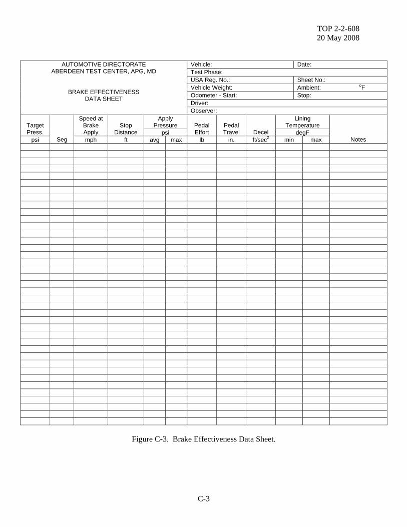
d. Test duration. e. Brake control force, if required. f. Brake temperature, if required. g. Comments on vehicle behavior. 5.2.3 Brake Effectiveness. a. Vehicle speed. b. Stopping distance. c. Brake apply pressure. d. Deceleration rate. e. Temperature of brakes. f. Steering correction, if required. g. Comments on vehicle behavior or brake noise. h. Test course skid number. i. Brake Effectiveness Data Sheet located in Appendix C, page C-3, can be used. 5.2.4 Brake Recovery After Water Immersion. a. Initial vehicle speed. b. Brake input pressure. c. Number of brake application to full recovery. d. Time of each brake application. e. Deceleration rate. f. Distance traveled. 5.2.5 Trailer Breakaway. a. Vehicle weight.
TOP 2-2-608 20 May 2008
18
b. Slope grade. c. Vehicle attitude. d. Time of test. 5.2.6 Emergency Braking (Single Point Failure). a. Initial vehicle speed. b. Brake input pressure. c. Stopping distance. d. Deceleration rate. e. Initial brake temperature. f. Comments on vehicle behavior and wheel lock-up. 5.2.7 Trailer Compatibility. a. Threshold pressure. b. Brake force. c. Vehicle speed. d. Deceleration rate. e. Lining temperature. 5.2.8 Maximum Pedal Effort Braking (maximum safe speed). a. Vehicle speed and direction. b. Stopping distance. c. Deceleration rate. d. Wheel locking. e. Vehicle slew. If required, data obtained from inspection of wheel, brake, and suspension system components.

TOP 2-2-608 20 May 2008
19
5.2.9 Constant, Split, and Changing Friction Surface Tests. a. Vehicle speed. b. Stopping distance. c. Deceleration rate. d. Brake apply pressure. e. Brake lining temperature. f. Lateral deviation. g. Yaw rate (optional). h. Wheel speed (optional). i. Wheel locking location. j. Maximum drive through speed. k. Test course skid number. 5.2.10 Regenerative Brake Performance. a. Vehicle speed. b. Engine speed. c. Stopping distance. d. Brake apply pressure. e. Deceleration rate. f. Brake temperature. g. Test course description (skid number, if applicable). h. Current and voltage of specific driveline components. i. Traction battery ventilation temperatures. j. Traction battery coolant temperatures.
TOP 2-2-608 20 May 2008
20
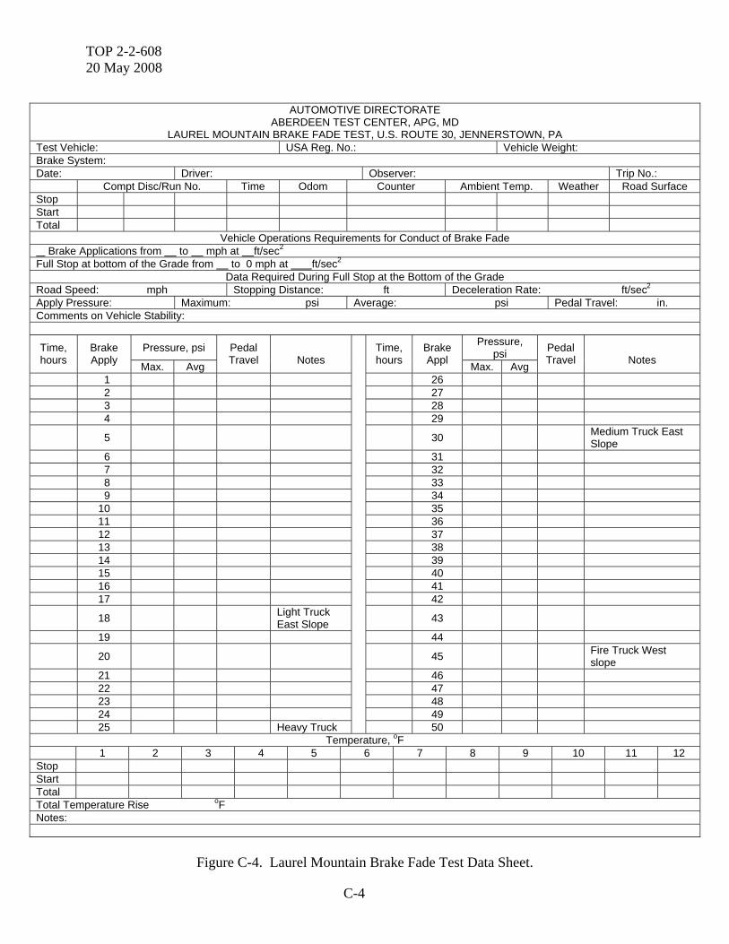
k. Traction battery module (cell) temperatures. l. Traction battery module (cell) voltages. 5.2.11 Auxiliary Braking Devices. a. Vehicle weight. b. Vehicle speed. c. Deceleration time. d. Resistance-to-motion force and power. e. Test configuration (gear range and/or auxiliary brake setting). f. Efficiency. g. Brake temperature rise. h. Number of brake snubs per test run. 5.3 Endurance /Durability Testing. 5.3.1 Structural Integrity. a. Vehicle speed. b. Brake lining temperature. c. Deceleration rate. d. Brake apply pressure. 5.3.2 Low Temperature Effects. a. Ambient temperature and humidity test conditions. b. Any damage to brake system components. 5.3.3 Mountain Highway Brake System Tests. 5.3.3.1 Brake Fade Test. Data required will be in accordance with the data sheet in Appendix C, Figure C-4.
TOP 2-2-608 20 May 2008
21
5.3.3.2 High Temperature Endurance Test. Data required will be in accordance with the data sheets in Appendix C, Figures C-1 through C-3 and C-5 through C-7. 5.3.4 Brake Durability and Wear. a. Vehicle mileage. b. Test course description/conditions. c. Brake stopping distances prior to, during, and after the endurance test. d. Extent of damage sustained by braking system components. e. Label and retain all failed parts and samples of fluids 6. PRESENTATION OF DATA. 6.1 Brake System Inspection/Characterization. a. Listing of vehicle and brake system descriptions (use SAE J1626, data sheet 1 as a guide). b. Tabulation of average brake apply and release times versus axle location. c. Tabulation of service and parking brake forces, service and parking brake force to weight ratios, and rolling resistance to weight ratio versus individual wheel location. d. Graph depicting brake pedal effort versus input pressure. 6.2 Safety/Performance Evaluation. a. Graphs. (1) Stopping distance and deceleration rate versus input pressure. (2) Stopping distance and deceleration rate versus road speed. (3) Brake recovery; stopping distance versus number of application. (4) Resistance-to-motion force and power versus road speed for each transmission and/or auxiliary brake condition.

TOP 2-2-608 20 May 2008
22
b. Tabulations. (1) Maximum grade holding ability for each brake applied and vehicle direction. (2) Stopping distance and deceleration rate versus road speed. (3) Trailer compatibility; threshold pressure and brake force for each wheel location and average maximum brake temperature for each wheel following brake snubbing procedure. (4) Target stopping distance, normalized stopping distance, and deceleration rate versus test course surface friction condition. (5) Notation of vehicle behavior, brake noise, wheel locking, steering correction, etc. (6) Maximum drive through speed and performance ratio achieved during low-friction surface lane change testing. (7) Regenerative braking; (a) Energy developed/consumed by each major component (motor generator, traction motor, traction battery, resistance grid) for each test performed. (b) Energy recovery (ratio of the traction battery energy to the developed traction motor energy) during each braking event. (c) Energy losses (ratio of motor generator and/or resistance grid energy change to the traction motor energy developed) during each braking event. (d) Computed efficiencies for each vehicle configuration, speed, and/or duty cycle. (8) Resistance-to-motion force and power versus road speed for each transmission and/or auxiliary brake setting. (9) Power absorbed by the auxiliary brake and its percentage of available engine power (efficiency) versus road speed. 6.3 Endurance/Durability Testing. a. Graphs. (1) Brake effectiveness from 32 and 64 km/hr; stopping distance and deceleration rate versus input pressure. (2) Brake fade and endurance test temperature profile; lining temperature versus time.
TOP 2-2-608 20 May 2008
23
b. Tabulations. (1) Low temperature effects; listing of damage to brake system components. (2) Brake drum/disc and lining/pad wear characteristics versus wheel location. (3) Brake effectiveness from 32 and 64 km/hr; stopping distance and deceleration rate versus input pressure. (4) Brake fade test; lining temperature, input pressure, vehicle speed, stopping distance, deceleration rate, for each fade test run. (5) High temperature endurance test; average and maximum lining temperatures and average input pressure for each cross-country run.

TOP 2-2-608 20 May 2008
A-1
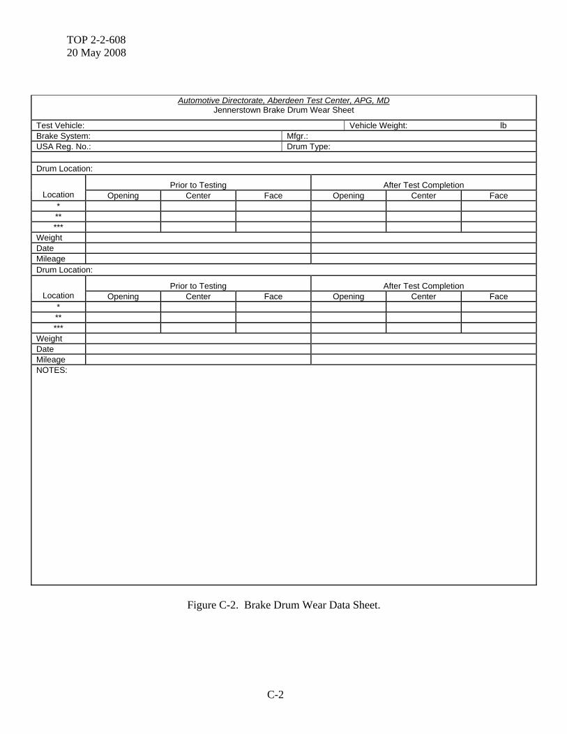
APPENDIX A. MOUNTAIN HIGHWAY BRAKE TEST OUTLINE 1. Disassemble brake system completely. 2. Provide all new brake components. 3. Make pertinent initial brake component measurements, recording data on forms shown in Figures C-1 and C-2. 4. Install calibrated brake test instrumentation (Paragraph 2.2). 5. Reassemble brake system. 6. Adjust lining material to drum clearances to manufacturer's specifications. 7. Bleed hydraulically actuated brake systems per manufacturer's recommended procedure. 8. Run pre-burnish effectiveness tests from 32 km/hr. 9. Burnish brakes to achieve at least 80 percent contact between the surface areas of the lining and the drum (use procedure summarized in Appendix B). 10. Readjust brakes to recommended clearances. 11. Measure pedal force requirements over brake input pressure range. 12. Run initial effectiveness tests from 32 and 64 km/hr (reference Paragraph 4.2.3), recording data on form shown as Figure C-3 13. Run Fade Test No.1 (east side of Laurel Mountain, Figure A-1), operating the vehicle downgrade and accelerating between brake applications as necessary to achieve required number of applications. a. Snubbing and stopping rates per vehicle gross weight are as follows:
TOP 2-2-608 20 May 2008
A-2
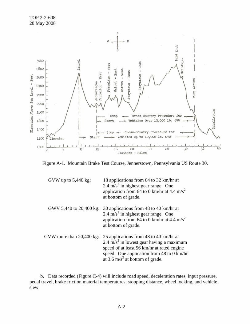
Figure A-1. Mountain Brake Test Course, Jennerstown, Pennsylvania US Route 30.
GVW up to 5,440 kg: 18 applications from 64 to 32 km/hr at 2.4 m/s2 in highest gear range. One application from 64 to 0 km/hr at 4.4 m/s2 at bottom of grade. GWV 5,440 to 20,400 kg: 30 applications from 48 to 40 km/hr at 2.4 m/s2 in highest gear range. One application from 64 to 0 km/hr at 4.4 m/s2 at bottom of grade.
GVW more than 20,400 kg: 25 applications from 48 to 40 km/hr at
2.4 m/s2 in lowest gear having a maximum speed of at least 56 km/hr at rated engine speed. One application from 48 to 0 km/hr at 3.6 m/s2 at bottom of grade.
b. Data recorded (Figure C-4) will include road speed, deceleration rates, input pressure, pedal travel, brake friction material temperatures, stopping distance, wheel locking, and vehicle slew.
TOP 2-2-608 20 May 2008
A-3
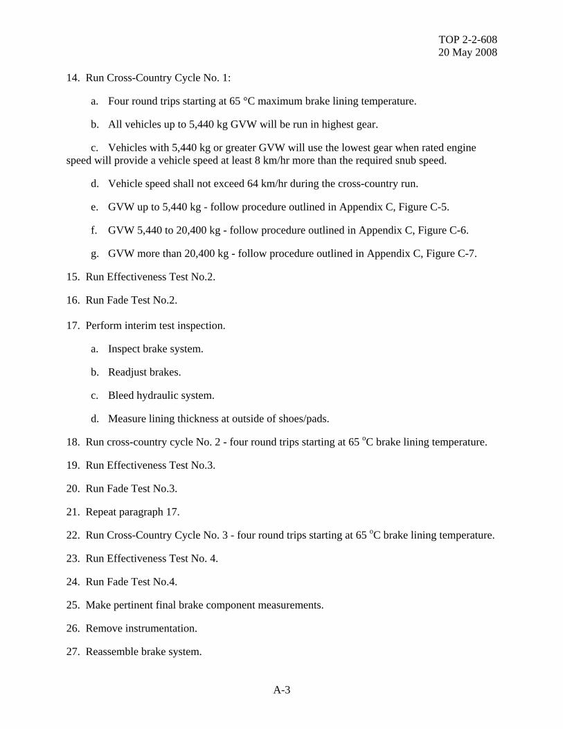
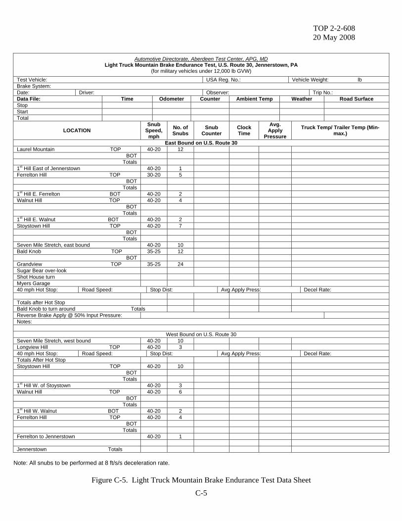
14. Run Cross-Country Cycle No. 1: a. Four round trips starting at 65 °C maximum brake lining temperature. b. All vehicles up to 5,440 kg GVW will be run in highest gear. c. Vehicles with 5,440 kg or greater GVW will use the lowest gear when rated engine speed will provide a vehicle speed at least 8 km/hr more than the required snub speed. d. Vehicle speed shall not exceed 64 km/hr during the cross-country run. e. GVW up to 5,440 kg - follow procedure outlined in Appendix C, Figure C-5. f. GVW 5,440 to 20,400 kg - follow procedure outlined in Appendix C, Figure C-6. g. GVW more than 20,400 kg - follow procedure outlined in Appendix C, Figure C-7. 15. Run Effectiveness Test No.2. 16. Run Fade Test No.2.
17. Perform interim test inspection. a. Inspect brake system. b. Readjust brakes. c. Bleed hydraulic system. d. Measure lining thickness at outside of shoes/pads. 18. Run cross-country cycle No. 2 - four round trips starting at 65 oC brake lining temperature. 19. Run Effectiveness Test No.3. 20. Run Fade Test No.3. 21. Repeat paragraph 17. 22. Run Cross-Country Cycle No. 3 - four round trips starting at 65 oC brake lining temperature. 23. Run Effectiveness Test No. 4. 24. Run Fade Test No.4. 25. Make pertinent final brake component measurements. 26. Remove instrumentation. 27. Reassemble brake system.

TOP 2-2-608 20 May 2008
B-1
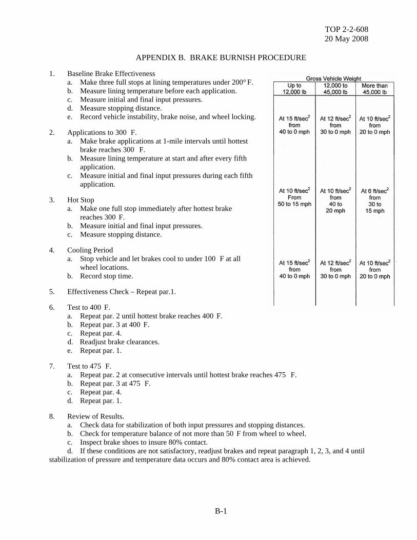
APPENDIX B. BRAKE BURNISH PROCEDURE 1. Baseline Brake Effectiveness a. Make three full stops at lining temperatures under 200° F. b. Measure lining temperature before each application. c. Measure initial and final input pressures. d. Measure stopping distance. e. Record vehicle instability, brake noise, and wheel locking. 2. Applications to 300 F. a. Make brake applications at 1-mile intervals until hottest brake reaches 300 F. b. Measure lining temperature at start and after every fifth application. c. Measure initial and final input pressures during each fifth application. 3. Hot Stop a. Make one full stop immediately after hottest brake reaches 300 F. b. Measure initial and final input pressures. c. Measure stopping distance. 4. Cooling Period a. Stop vehicle and let brakes cool to under 100 F at all wheel locations. b. Record stop time. 5. Effectiveness Check – Repeat par.1. 6. Test to 400 F. a. Repeat par. 2 until hottest brake reaches 400 F. b. Repeat par. 3 at 400 F. c. Repeat par. 4.
d. Readjust brake clearances. e. Repeat par. 1. 7. Test to 475 F. a. Repeat par. 2 at consecutive intervals until hottest brake reaches 475 F. b. Repeat par. 3 at 475 F. c. Repeat par. 4. d. Repeat par. 1. 8. Review of Results. a. Check data for stabilization of both input pressures and stopping distances. b. Check for temperature balance of not more than 50 F from wheel to wheel. c. Inspect brake shoes to insure 80% contact. d. If these conditions are not satisfactory, readjust brakes and repeat paragraph 1, 2, 3, and 4 until stabilization of pressure and temperature data occurs and 80% contact area is achieved.
TOP 2-2-608
20 M
ay 2008
B-2
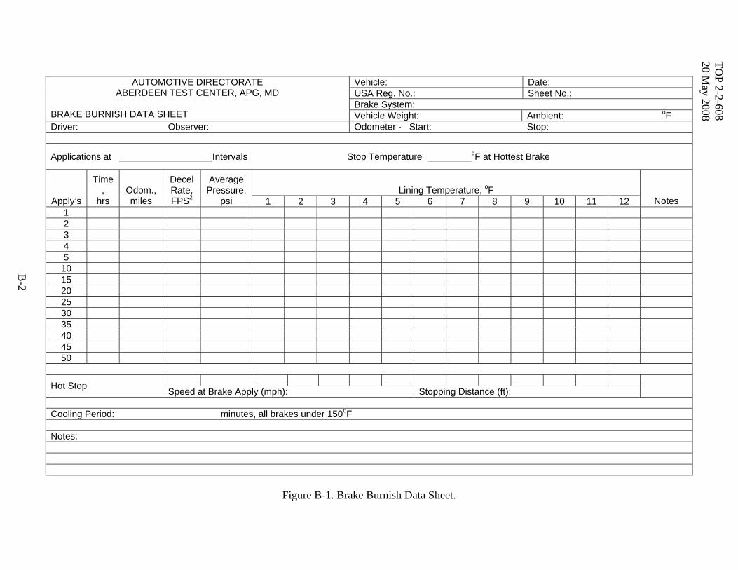
Figure B-1. Brake Burnish Data Sheet.
Vehicle: Date: USA Reg. No.: Sheet No.: Brake System:
AUTOMOTIVE DIRECTORATE ABERDEEN TEST CENTER, APG, MD
BRAKE BURNISH DATA SHEET Vehicle Weight: Ambient: oF Driver: Observer: Odometer - Start: Stop:
Applications at Intervals Stop Temperature oF at Hottest Brake
Lining Temperature, oF Apply’s
Time,
hrs Odom., miles
Decel Rate, FPS2
Average Pressure,
psi 1 2 3 4 5 6 7 8 9 10 11 12 Notes 1 2 3 4 5 10 15 20 25 30 35 40 45 50
Hot Stop Speed at Brake Apply (mph): Stopping Distance (ft):
Cooling Period: minutes, all brakes under 150oF
Notes:
TOP 2-2-608 20 May 2008
C-1
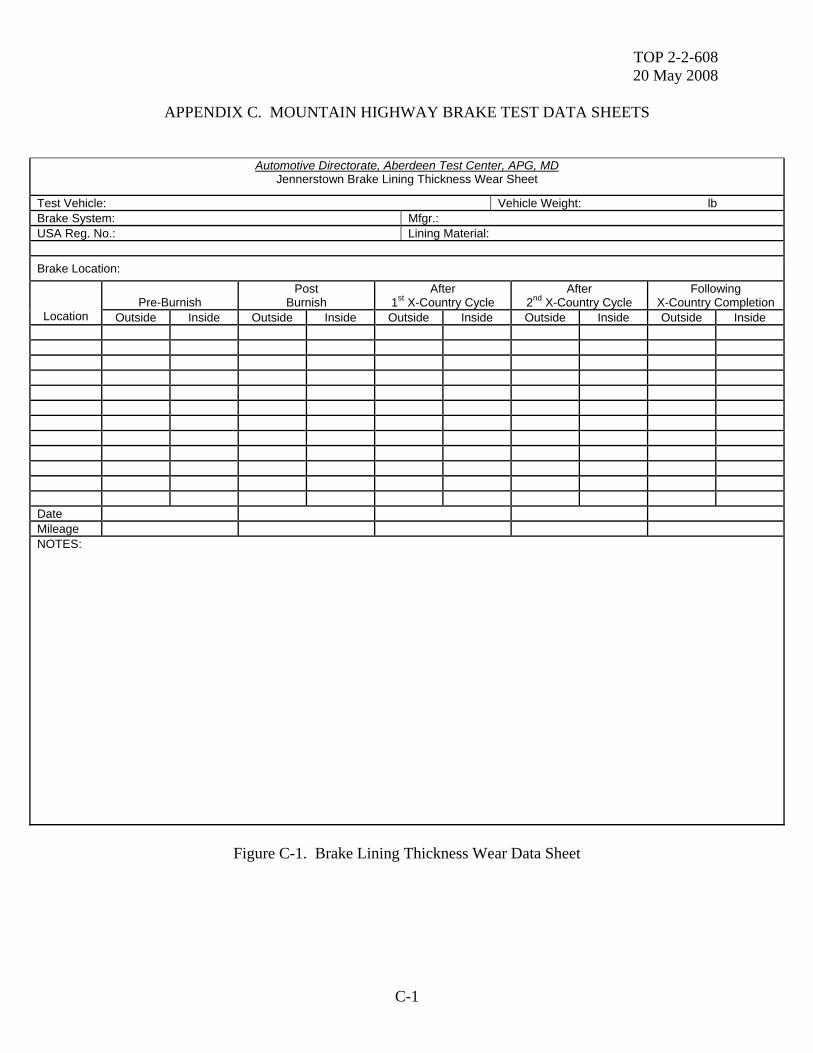
APPENDIX C. MOUNTAIN HIGHWAY BRAKE TEST DATA SHEETS
Automotive Directorate, Aberdeen Test Center, APG, MD Jennerstown Brake Lining Thickness Wear Sheet
Test Vehicle: Vehicle Weight: lb Brake System: Mfgr.: USA Reg. No.: Lining Material:
Brake Location:
Pre-Burnish Post
Burnish After
1st X-Country Cycle After
2nd X-Country Cycle Following
X-Country Completion Location Outside Inside Outside Inside Outside Inside Outside Inside Outside Inside
Date Mileage NOTES:
Figure C-1. Brake Lining Thickness Wear Data Sheet
TOP 2-2-608 20 May 2008
C-2
Automotive Directorate, Aberdeen Test Center, APG, MD Jennerstown Brake Drum Wear Sheet
Test Vehicle: Vehicle Weight: lb Brake System: Mfgr.: USA Reg. No.: Drum Type: Drum Location:
Prior to Testing After Test Completion Location Opening Center Face Opening Center Face
* ** ***
Weight Date Mileage Drum Location:
Prior to Testing After Test Completion Location Opening Center Face Opening Center Face
* ** ***
Weight Date Mileage NOTES:
Figure C-2. Brake Drum Wear Data Sheet.
TOP 2-2-608 20 May 2008
C-3
Vehicle: Date: Test Phase: USA Reg. No.: Sheet No.: Vehicle Weight: Ambient: oF Odometer - Start: Stop: Driver:
AUTOMOTIVE DIRECTORATE ABERDEEN TEST CENTER, APG, MD
BRAKE EFFECTIVENESS DATA SHEET
Observer: Apply
Pressure Lining
Temperature Target Press.
Speed at Brake Apply
Stop Distance psi
Pedal Effort
Pedal Travel Decel degF
psi Seg mph ft avg max lb in. ft/sec2 min max Notes
Figure C-3. Brake Effectiveness Data Sheet.
TOP 2-2-608 20 May 2008
C-4
AUTOMOTIVE DIRECTORATE
ABERDEEN TEST CENTER, APG, MD LAUREL MOUNTAIN BRAKE FADE TEST, U.S. ROUTE 30, JENNERSTOWN, PA
Test Vehicle: USA Reg. No.: Vehicle Weight: Brake System: Date: Driver: Observer: Trip No.:
Compt Disc/Run No. Time Odom Counter Ambient Temp. Weather Road Surface Stop Start Total
Vehicle Operations Requirements for Conduct of Brake Fade Brake Applications from to mph at ft/sec2 Full Stop at bottom of the Grade from to 0 mph at ft/sec2
Data Required During Full Stop at the Bottom of the Grade Road Speed: mph Stopping Distance: ft Deceleration Rate: ft/sec2 Apply Pressure: Maximum: psi Average: psi Pedal Travel: in. Comments on Vehicle Stability:
Pressure, psi Pressure, psi Time,
hours Brake Apply Max. Avg
Pedal Travel
Notes
Time, hours
Brake Appl Max. Avg
Pedal Travel
Notes
1 26 2 27 3 28 4 29
5 30 Medium Truck East Slope
6 31 7 32 8 33 9 34 10 35 11 36 12 37 13 38 14 39 15 40 16 41 17 42
18 Light Truck East Slope 43
19 44
20 45 Fire Truck West slope
21 46 22 47 23 48 24 49 25 Heavy Truck
50 Temperature, oF
1 2 3 4 5 6 7 8 9 10 11 12 Stop Start Total Total Temperature Rise oF Notes:
Figure C-4. Laurel Mountain Brake Fade Test Data Sheet.
TOP 2-2-608 20 May 2008
C-5
Note: All snubs to be performed at 8 ft/s/s deceleration rate.
Figure C-5. Light Truck Mountain Brake Endurance Test Data Sheet
Automotive Directorate, Aberdeen Test Center, APG, MD Light Truck Mountain Brake Endurance Test, U.S. Route 30, Jennerstown, PA
(for military vehicles under 12,000 lb GVW) Test Vehicle: USA Reg. No.: Vehicle Weight: lb Brake System: Date: Driver: Observer: Trip No.: Data File: Time Odometer Counter Ambient Temp Weather Road Surface Stop Start Total
LOCATION Snub
Speed, mph
No. of Snubs
Snub Counter
Clock Time
Avg. Apply
Pressure
Truck Temp/ Trailer Temp (Min-max.)
East Bound on U.S. Route 30 Laurel Mountain TOP 40-20 12
BOT Totals
1st Hill East of Jennerstown 40-20 1 Ferrelton Hill TOP 30-20 5
BOT Totals
1st Hill E. Ferrelton BOT 40-20 2 Walnut Hill TOP 40-20 4
BOT Totals
1st Hill E. Walnut BOT 40-20 2 Stoystown Hill TOP 40-20 7
BOT Totals
Seven Mile Stretch, east bound 40-20 10 Bald Knob TOP 35-25 12
BOT Grandview TOP 35-25 24 Sugar Bear over-look Shot House turn Myers Garage 40 mph Hot Stop: Road Speed: Stop Dist: Avg Apply Press: Decel Rate: Totals after Hot Stop Bald Knob to turn around Totals Reverse Brake Apply @ 50% Input Pressure: Notes:
West Bound on U.S. Route 30 Seven Mile Stretch, west bound 40-20 10 Longview Hill TOP 40-20 3 40 mph Hot Stop: Road Speed: Stop Dist: Avg Apply Press: Decel Rate: Totals After Hot Stop Stoystown Hill TOP 40-20 10
BOT Totals
1st Hill W. of Stoystown 40-20 3 Walnut Hill TOP 40-20 6
BOT Totals
1st Hill W. Walnut BOT 40-20 2 Ferrelton Hill TOP 40-20 4
BOT Totals
Ferrelton to Jennerstown 40-20 1 Jennerstown Totals
TOP 2-2-608 20 May 2008
C-6
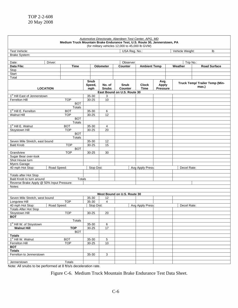
Automotive Directorate, Aberdeen Test Center, APG, MD
Medium Truck Mountain Brake Endurance Test, U.S. Route 30, Jennerstown, PA (for military vehicles 12,000 to 45,000 lb GVW)
Test Vehicle: USA Reg. No.: Vehicle Weight: lb Brake System: Date: Driver: Observer: Trip No.: Data File: Time Odometer Counter Ambient Temp Weather Road Surface Stop Start Total
LOCATION
Snub Speed,
mph
No. of Snubs
Snub
Counter
Clock Time
Avg. Apply
Pressure Truck Temp/ Trailer Temp (Min-
max.)
East Bound on U.S. Route 30 1st Hill East of Jennerstown 35-30 3 Ferrelton Hill TOP 30-25 10
BOT Totals
1st Hill E. Ferrelton BOT 35-30 6 Walnut Hill TOP 30-25 12
BOT Totals
1st Hill E. Walnut BOT 35-30 4 Stoystown Hill TOP 30-25 20
BOT Totals
Seven Mile Stretch, east bound 35-30 12 Bald Knob TOP 30-25 15
BOT Grandview TOP 30-25 30 Sugar Bear over-look Shot House turn Myers Garage 40 mph Hot Stop: Road Speed: Stop Dist: Avg Apply Press: Decel Rate: Totals after Hot Stop Bald Knob to turn around Totals Reverse Brake Apply @ 50% Input Pressure: Notes:
West Bound on U.S. Route 30 Seven Mile Stretch, west bound 35-30 12 Longview Hill TOP 35-30 4 40 mph Hot Stop: Road Speed: Stop Dist: Avg Apply Press: Decel Rate: Totals After Hot Stop Stoystown Hill TOP 30-25 20 BOT
Totals 1st Hill W. of Stoystown 35-30 6
Walnut Hill TOP 30-25 17 BOT
Totals 1st Hill W. Walnut BOT 35-30 5 Ferrelton Hill TOP 30-25 10 BOT Totals Ferrelton to Jennerstown 35-30 3 Jennerstown Totals
Note: All snubs to be performed at 8 ft/s/s deceleration rate.
Figure C-6. Medium Truck Mountain Brake Endurance Test Data Sheet.
TOP 2-2-608 20 May 2008
C-7
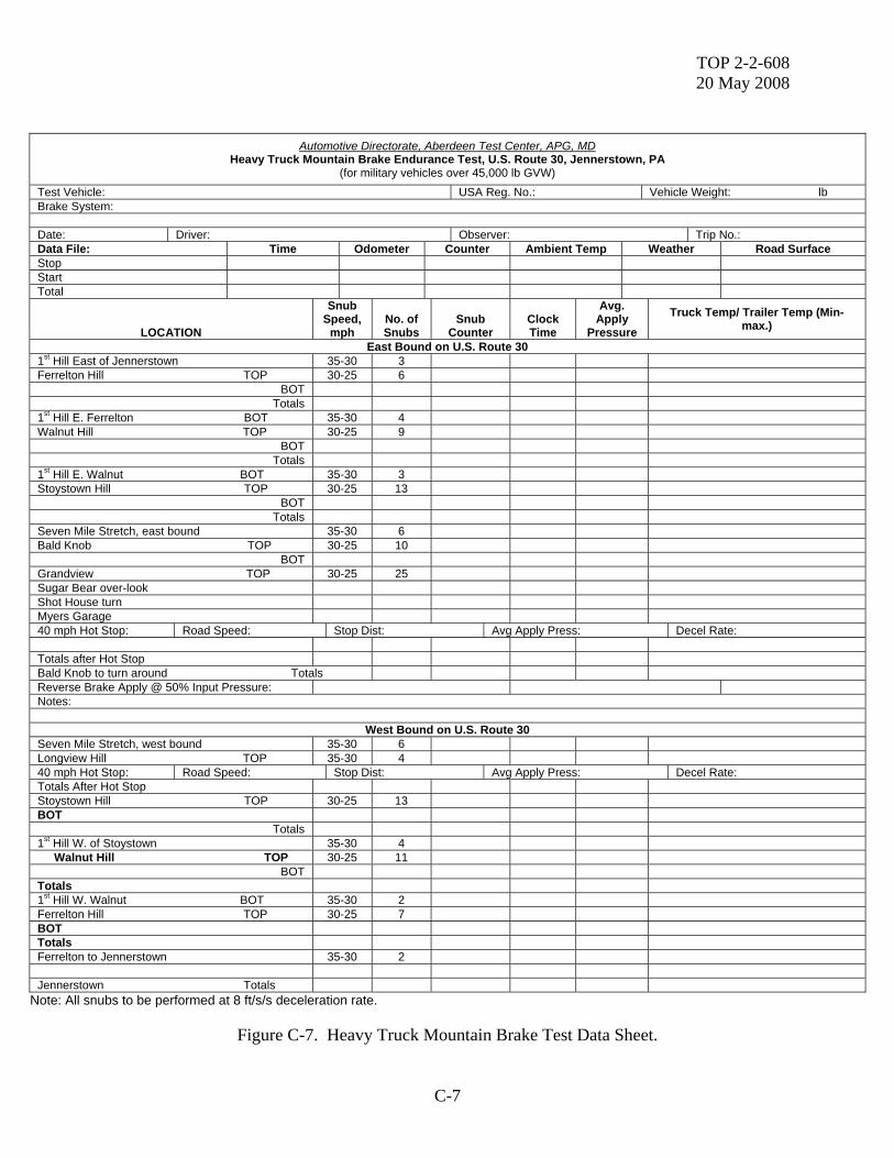
Automotive Directorate, Aberdeen Test Center, APG, MD
Heavy Truck Mountain Brake Endurance Test, U.S. Route 30, Jennerstown, PA (for military vehicles over 45,000 lb GVW)
Test Vehicle: USA Reg. No.: Vehicle Weight: lb Brake System: Date: Driver: Observer: Trip No.: Data File: Time Odometer Counter Ambient Temp Weather Road Surface Stop Start Total
LOCATION
Snub Speed,
mph
No. of Snubs
Snub
Counter
Clock Time
Avg. Apply
Pressure Truck Temp/ Trailer Temp (Min-
max.)
East Bound on U.S. Route 30 1st Hill East of Jennerstown 35-30 3 Ferrelton Hill TOP 30-25 6
BOT Totals
1st Hill E. Ferrelton BOT 35-30 4 Walnut Hill TOP 30-25 9
BOT Totals
1st Hill E. Walnut BOT 35-30 3 Stoystown Hill TOP 30-25 13
BOT Totals
Seven Mile Stretch, east bound 35-30 6 Bald Knob TOP 30-25 10
BOT Grandview TOP 30-25 25 Sugar Bear over-look Shot House turn Myers Garage 40 mph Hot Stop: Road Speed: Stop Dist: Avg Apply Press: Decel Rate: Totals after Hot Stop Bald Knob to turn around Totals Reverse Brake Apply @ 50% Input Pressure: Notes:
West Bound on U.S. Route 30 Seven Mile Stretch, west bound 35-30 6 Longview Hill TOP 35-30 4 40 mph Hot Stop: Road Speed: Stop Dist: Avg Apply Press: Decel Rate: Totals After Hot Stop Stoystown Hill TOP 30-25 13 BOT
Totals 1st Hill W. of Stoystown 35-30 4
Walnut Hill TOP 30-25 11 BOT
Totals 1st Hill W. Walnut BOT 35-30 2 Ferrelton Hill TOP 30-25 7 BOT Totals Ferrelton to Jennerstown 35-30 2 Jennerstown Totals
Note: All snubs to be performed at 8 ft/s/s deceleration rate.
Figure C-7. Heavy Truck Mountain Brake Test Data Sheet.


TOP 2-2-608 20 May 2008
D-1
APPENDIX D: BRAKE SYSTEM INSPECTION PROCEDURES
Hydraulic Brake Systems Regardless of the number of axles, all vehicles fitted with original equipment brakes by the manufacturer must have those brakes in proper working order before the vehicle can pass inspection. If the front axle brakes are fitted but are not operative, the front brakes must be returned to the proper working order before the vehicle can pass inspection. If the original manufacturer’s front axle brake components have been removed, they must be replaced and the front brake system brought into proper working order. Properly functioning brakes must be fitted on a all two- and three-axle trucks and two-axle truck tractors before a vehicle can pass inspection. In the United States, trucks and truck tractors, with three or more axles require front brakes if manufactured after July 24, 1980. In Canada, truck tractors manufactured without front brakes must be fitted with front brakes to OEM specifications for the axle by January 1, 1995, if the vehicle is converted for use as a straight truck (subject to provincial legislation). Internal components of brake systems should be inspected as follows: 1. When evidence of defect(s) on internal brake components is disclosed during inspection of external or internal brake components, the affected brake drum(s) should be removed for further inspection and repair. 2. When no evidence of brake defect(s) exists, inspection of internal components should be performed as follows: a. Remove brake drums and inspect the internal brake components, measure and record the internal brake drum diameter, and measure and record the brake lining edge thickness at the center of the brake shoe; or b. If fitted with removable dust shields or no dust shields are in place; with the dust shields removed, inspect the internal brake components, measure and record the internal brake drum diameter, and measure and record the brake lining edge thickness at the center of the brake shoe. c. If fitted with non-removable dust shields or backing plates: (1) When the owner provides proof that wheel removal and inspection of internal brake components was conducted within the preceding 24 months, perform a visual inspection through the inspection holes;
TOP 2-2-608 20 May 2008
D-2
(2) When proof of wheel removal is not provided by the owner or no inspection holes are present, remove the brake drum(s) and inspect the internal brake components, measure and record the internal brake drum diameter, and measure and record the brake lining edge thickness at the center of the brake shoe. Note: Proof of brake drum removal and inspection of internal brake components should include the brake drum diameter and brake lining thickness measurements. The registered owner of the vehicle or a person designated by the owner is responsible for providing proof of inspection of the internal brake components. 1. Parking Brakes Procedure: Step 1: With the engine idling, apply parking brakes. Place and automotive transmission into drive. For a manual transmission, shift into gear and partially engage the clutch. Step 2: Visually inspect the function of the parking brakes, indicator lamp (if equipped), brake application, mechanism, cables (If equipped) and lining (if equipped). Reject the vehicle if:
• The parking brake fails to hold. • The indicator lamp (if equipped) fails to illuminate. • The parking brake fails to fully apply or release. • The mechanism binds or is inoperable. • Cables are frayed, broken or missing. • Lining (if equipped) is less than 1.6 mm (1/16 inch) above the shoe on an external
clamping type. HAZARDOUS CONDITION
• The brake fails to hold the vehicle when the parking brake is actuated. 2. Hydraulic System Procedure: Visually inspect the lines, hoses, master cylinder and cap. Reject the vehicle if:
• Lines and hoses are leaking, welded, cracked, chafed, flattened, insecurely mounted or have restricted sections.
• Repairs to lines and hoses have been made with anything other than steel tubing. • Connections are anything other than double flared. • The master cylinder is leaking, loose or the fluid level is below 12.7 mm (1/2 inch) from
the top. • The cap is missing or loose, vent holes are plugged, or the gasket is missing or damaged.
TOP 2-2-608 20 May 2008
D-3
HAZARDOUS CONDITION • Any brake hose or line seeps or swells under pressure. • Any brake hose is cracked to the second layer. • The master cylinder reservoir is less than one-quarter full.
3. Dual Hydraulic Circuit Step 1: Visually and manually inspect the warning indicator. Reject the vehicle if the warning indicator lamp illuminates in the “ON” position, it fails to operate in a “START” position, or it operates continuously. Step 2: With the engine running, press the brake pedal with a heavy foot force (about 55 kg/125 lbs. force) and inspect the pressure differential switch. Observe the warning lamp. Reject the vehicle if the warning indicator lamp comes on. HAZARDOUS CONDITION
• The brake failure lamp illuminates continuously. 4. Hydraulic Brake Leakage and Pedal Reserve Procedure: If testing power brakes, do this procedure with the engine running. Apply a moderate foot force to the pedal and maintain for one minute. Do not pump or repeatedly apply the brake pedal. Using a measuring device, visually inspect for leakage and brake pedal travel. Reject the vehicle if:
• The pedal moves in applied direction. • Pedal travel from its free height to its depressed height is more that 65 percent of this
total or does not meet manufacturer’s specifications. HAZARDOUS CONDITION
• Any fluid leakage is observed in the system. • The service brake pedal requires pumping to maintain the pedal reserve. • Pedal free play exceeds 80 percent.
5. Hydraulic System with Hydraulic Assist Procedure: Step 1: Inspect for leakage and test the pedal reserve following the same procedures and rejection criteria as above in Chapter 3, Item 4. Vehicles equipped with an electrically driven hydraulic pump that functions in the event of a power steering failure, can be checked by applying moderate pressure on the brake pedal. Visually and audibly inspect pedal travel, the warning indicator lamp (if applicable), pump reservoir, lines, hoses, belt and motor operation.
TOP 2-2-608 20 May 2008
D-4
Reject the vehicle if: • No movement in the pedal is detected. • The warning indicator lamp is inoperable when the power steering pump is stopped. • The pump reservoir is below the indicated “ADD” mark. • Lines and hoses are leaking. • The belt is loose, cracked or excessively worn. • The motor fails to operate when the engine is not running. Step 2: With the ignition in the “OFF” position and the engine stopped, depress the brake pedal several times. Apply moderate foot pressure on the brake pedal and start the engine. Reject the vehicle if no pedal movement is observed.
HAZARDOUS CONDITION
• Power assist unit fails to operate. • The service brake pedal does not move toward the floorboard with the brakes applied
when the engine is started. 6. Vacuum System Procedure: Visually and manually inspect the lines and hoses, and the condition of the system, clamps and tank(s). Reject the vehicle if:
• Lines and hoses are collapsed, broken, chafed, insecurely mounted, less than 38 mm (1.5 inch) from any part of the exhaust system.
• The system is leaking. • Clamps are loose, missing or broken. • Any tank is missing, loose, damaged or leaking.
HAZARDOUS CONDITION
• Power assist unite fails to operate. • The check valve is missing or inoperative. • The service brake pedal does not move toward the floorboard with the brakes applied
when the engine is started. 7. Vacuum Booster Procedure: With the engine off, press the brake pedal several times to eliminate vacuum. Apply light force on the brake pedal (12 kg/25 lbs.) and then start the ending. Visually inspect the vacuum booster operation and condition.
TOP 2-2-608 20 May 2008
D-5
Reject the vehicle if: • Brake pedal movement cannot be detected. • The vacuum booster is loose, damaged, or the mounting is cracked.
HAZARDOUS CONDITION
• The power assist unit fails to operate. • The check valve is missing or inoperative. • The service brake pedal does not move toward the floorboard with the brakes applied
when the engine is started. 8. Vacuum Reserve Procedure: Start the engine and build up full vacuum. Shut the engine off and make three full brake applications. Manually and visually inspect the pedal reserve and the buzzer or brake indicator lamp (if applicable). Reject the vehicle if:
• The pedal reserve is insufficient to assist three full applications • The brake indicator lamp or buzzer fails to operate when the system is reduced to 2 kpa
(8 inches) of vacuum, or it operates continuously after one application. 9. Vacuum Pump Procedure: Step 1: If a vehicle is equipped with a vacuum pump, deplete all vacuum by pumping the brakes. If the system also uses engine vacuum, disconnect the source. Step 2: Operate the engine at approximately 1,200 rpm. Visually inspect the reserve. Reject the vehicle if:
• The vacuum pump is unable to achieve and maintain 4.5 kpa (18 inches) of vacuum.
HAZARDOUS CONDITION • The power assist unit fails to operate.
10. Front Drum Brakes Procedure: Equipment needed: Steel scale or Vernier caliper. Step 1: Visually inspect and measure the bonded lining for wear and condition.
TOP 2-2-608 20 May 2008
D-6
Reject the vehicle if: • Bonded lining is worn to 1.6 mm (1/16 inch) or less at the center or at any point other
than the chamfered area of the shoe. • Bonded lining is cracked, insecurely bonded to the shoe, contaminated or worn extremely
unevenly.
Step 2: Visually inspect and measure the riveted lining for wear and condition. Reject the vehicle if:
• Riveted lining is worn to 3.2 mm (1/8 inch) or less at the center or at any point other than the chamfered area of the shoe.
• Riveted lining is broken, cracked, contaminated or worn extremely unevenly. Step 3: Visually inspect the mechanical components including the self-adjusters, self-adjuster cables and linkage, anchor pins and springs, backing plate, and axle and spindles. Reject the vehicle if:
• Self-adjusters are seized, excessively worn, inoperable, missing or the wrong thread for the wheel has been installed.
• Self-adjuster cables and linkage are missing, loose, broken, inoperable or the cables are frayed.
• Anchor pins and springs are missing, loose, broken excessively worn or stretched. • The backing plate is worn so as to restrict free movement of the shoes. • The axle and spindles show evidence of cracking.
Step 4: Visually inspect the wheel cylinders for operation, condition and dust seals. Reject the vehicle if:
• Wheel cylinders are inoperable or seized. • Wheel cylinders are leaking, damaged or mounted insecurely. • Dust seals are damaged, missing or deteriorated.
Step 5: When the wheels are removed, the brake drums must be inspected as per this section. Visually inspect for the condition of the brake drums. Reject the vehicle if:
• Cracks extend to the open edge of the drum. • Any external cracks are present • Any hot spots that cannot be removed by machining drum limits are present in more than
three locations. • {CANADA} Friction surface is uneven.
Step 6: Measure the inside diameter of the drum at two different locations approximately 90 degrees apart. Equipment needed: A drum measuring gauge approved by the jurisdiction.
TOP 2-2-608 20 May 2008
D-7
Reject the vehicle if: • Drum has one or more grooves worn so that the measurement in the groove exceeds the
wear limit. • Drum is out of round more than 0.25 mm (.010 inch) on drums 280 mm (11 inches) in
diameter and smaller. • Drum is out of round more than 0.63 mm (.025 inch) on drums greater than 280 mm (11
inches) in diameter. • Drum exceeds specifications as set out in Chapter 3, Item 14.
Step 7: Apply the breaks and try to rotate the wheel. Reject the vehicle if the wheel rotates. HAZARDOUS CONDITION
• The brake drum is in a condition that would indicate that failure is imminent. 11. Front Disc Brakes Procedure: Step 1: Visually inspect and measure rotors, calipers, and pads. Equipment needed: Micrometer and dial indicator. Reject the vehicle if:
• Rotors are broken or damaged, or cracks on the surface extend to the outer edges. • Two grooves on the rotors are worn beyond the maximum 2.3 mm (0.09 inch). • Lateral runout exceeds 0.128 mm (.005 inch) on discs 380 mm (15 inches) in diameter or
less. • Lateral runout exceeds 0.25 mm (0.010 inch) on discs greater than 380 mm (15 inches). • Rotors exceed the wear limits in Chapter 3, Item 14. • Calipers are leaking, the piston is seized or the caliper is seized. • Pads are damaged, contaminated or worn to the following measurements:
o Bonded Pads: 1.6 mm (1/16 inch) or less at the thinnest point. o Riveted Lining: 3.2 mm (1/8 inch) or less at the thinnest point.
Step 2: Apply the brakes and attempt to rotate the wheel assembly. HAZARDOUS CONDITION
• Any rotor is cracked to the hub or failure appears to be imminent. 12. Rear Brakes Procedure: Step 1: Visually inspect and measure the lining for wear and condition.
TOP 2-2-608 20 May 2008
D-8
Equipment needed: Vernier caliper or a steel scale. Reject the vehicle if:
• Bonded lining is worn to 1.6 mm (1/16 inch) or less at the center or any point other than the chamfered area of the shoe.
• The bonded lining is cracked, contaminated or insecurely bonded to the shoe. • Riveted lining is worn to 3.2 mm (1/8 inch) or less at the center or at any point other than
the chamfered area of the shoe. • Riveted lining is broken, cracked or contaminated.
Step 2: Visually inspect the mechanical components of the rear brakes, including the self-adjusters, self-adjuster cable and linkage, anchor pins and springs, backing plate and the parking brake cables and linkage. Reject the vehicle if:
• Self-adjusters are seized, worn, inoperable, missing, or the wrong thread for the wheel is installed.
• The self-adjuster cable and linkage is missing, loose, broken, inoperable or the cables are frayed.
• Anchor pins and springs are missing, loose, broken, excessively worn or stretched. • The backing plate is worn so as to restrict free movement of the shoes. • The parking brake cables and linkage are missing, loose, broken, inoperable or the cables
are frayed. Step 3: Visually inspect the wheel cylinders. Reject the vehicle if:
• Wheel cylinders are inoperable or seized. • Wheel cylinders are leaking. • Dust seals are damaged, missing or deteriorated.
Step 4: Visually inspect the brake drums for condition and wear. Measure the inside diameter of the drum at two locations approximately 90 degrees apart using an approved gauge. Note: When wheels are removed the brake drums must be inspected as per this section. Reject the vehicle if:
• Cracks extend to the open edge of the drum • Any external cracks are present. • Hot spots than cannot be removed by machining within drum limits are present in more
than three locations. • The friction surface is uneven. • The drum has more than two grooves worn so that the measurement in the grooves
exceeds the wear limits as per Chapter 3, Item 14. • The drum is out-of-round more than 0.25 mm (0.010 inch) on drums 280 mm (11 inches)
and smaller.
TOP 2-2-608 20 May 2008
D-9
• Out-of-round is more than 0.63 mm (0.025 inch) on drums greater than 280 mm (11 inches).
• The drum exceeds wear limits as set out in Chapter 3, Item 14. HAZARDOUS CONDITION
• The brake drum is in a condition that indicated that failure is imminent. 13. Anti-lock Brake Systems (ABS) Trucks with hydraulic brakes manufactured after March 1, 1999, must be equipped with anti-lock brakes when they are operated in the United States. USA Procedure If a vehicle is equipped with an ABS, visually and manually inspect the warning light. Reject the vehicle if:
• The warning light fails to illuminate during the cycle or self-check, or a self-diagnostic error is indicated.
14. Machining and Wear Limits, Brake Drums and Rotors A. Brake Drums No combination of machining and wear may exceed the manufacturer’s stamped limit. If the manufacturer’s limit is not available, then no combination of wear and machining may exceed:
• 2.3 mm (0.090 inch) over original; drum diameter of 350 mm (14 inches) or less. • 3.0 mm (0.120 inch) over original; drum diameter of greater than 350 mm (14 inches).
B. Brake Rotors The original thickness may not be decreased by any combination of wear and machining below the manufacturer’s minimum thickness.
Air Actuated Brake Systems
Internal Brake Inspections: Regardless of the number of axels, all vehicles fitted with original equipment brakes by the manufacturer must have those brakes in proper working order before the vehicle can pass inspection. If the front axel brakes are fitted, but are not operative, the front brakes must be returned to proper working order before the vehicle can pass inspection.
TOP 2-2-608 20 May 2008
D-10
If the original manufacturer’s front axle brake components have been removed, they must be replaced and the front brake system brought into proper working order. Properly functioning brakes must be fitted on all two- and three-axles trucks and two-axle truck tractors before a vehicle can pass inspection. USA In the United States, trucks and truck tractors, with three or more axles require front brakes if manufactured after July 24, 1980. CANADA In Canada, truck-tractors manufactured without front brakes must be fitted with front brakes to OEM specifications for that axle by January 1, 1995, if the vehicle is converted for use as a straight truck (subject to provincial legislation). Internal components of brake systems should be inspected as follows: 1. When evidence of defect(s) on internal brake components is disclosed during inspection of external or internal brake components, the affected brake drum(s) should be removed for further inspection and repair. 2. When no evidence of defect(s) exists, inspection of internal components should be performed as follows: a. Remove brake drums and inspect internal brake components, measure and record internal brake drum diameter, and measure and record brake lining edge thickness as the center of the brake shoes: or b. If fitted with removable dust shields or no dust shields are in place: (1) With dust shields removes, inspect internal brake components, measure and record internal brake drum diameter and measure and record brake lining edge thickness at the center of the brake shoe; or (2) With dust shields removed, inspect the internal brake components, perform a camshaft rotation test and record the measurement obtained. c. If with non-removable dust shields: (1) When the owner provides proof that wheel removal and inspection of internal brake components was conducted within the preceding 24 months, perform a camshaft rotation test and record the measurement. (2) When proof of wheel removal is not provided, remove brake drum(s) and inspect the internal broke components, measure and record the internal brake drum diameter, and measure and record the brake lining edge thickness at the center of the brake shoe. Note: Proof of brake drum removal and inspection of internal brake components should include the brake drum inside diameter and braking lining thickness measurements. The registered owner of the vehicle or a person designated by the owner is responsible for providing proof of inspection of internal brake components.
TOP 2-2-608 20 May 2008
D-11
1. Air Compressor Procedure: Manually and visually inspect the compressor, belts (if so equipped), compressor mount (if so equipped), air filter and pulley (if so equipped). Reject the vehicle if:
• The compressor is loose. • Belts are deteriorated, frayed loose (maximum deflection of 12.7 to 19 mm (1/2 to ¾
inch). • The compressor mount is loose, cracked or bolts are missing. • The air filter is missing or contaminated to as to affect the airflow. • The pulley is bent or damaged.
HAZARDOUS CONDITION
• A belt or pulley is in such a condition or contaminated so as to affect the airflow • The compressor is mounted insecurely and has shifted from its normal position.
2. Compressor Air-build time Procedure With the spring brakes released, and with the wheel chocked, reduce the pressure in the system until the pressure gauge indicator is less than 350 kpa (50psi). Run the engine at 1200 rpm and record the time required to raiser the air pressure from 350 to 600 kpa (50 to 90 psi) on the gauge. Inspect the air-build time. Reject the vehicle if:
• Air-build time exceeds three minutes. 3. Air Governor Procedure: Step 1: Continue running the engine and observe the gauge pressure when the governor cuts out. Reject the vehicle if:
• The gauge pressure is not between 805 and 945 kpa (115 to 135 psi). Step 2: with the spring brakes released at maximum pressure and with the engine idling, make a rapid serious of brake applications and observe the gauge pressure when the governor cuts in. Reject the vehicle if:
• The governor cut-in pressure is below 560 kpa (80 psi).
TOP 2-2-608 20 May 2008
D-12
4. Low Air Pressure Warning System Procedure: Visually and audibly inspect the warning system (lamp, buzzer, or wig-wag). Reject the vehicle if:
• The warning system fails to operate below 382 kpa (55 psi) or one-half governor cut-out pressure, whichever is less.
• The warning system is missing. HAZARDOUS CONDITION
• The warning system is missing or fails to operate below 382 kpa (55 psi). 5. Air system Leakage Procedure: With a fully charged air system and with the spring brakes released, make a full service brake application. Shut down the engine and record the pressure drop in kpa (psi) per minute. Conduct the test for at least two minutes. Inspect for leakage. Reject the vehicle if:
• The pressure drop exceeds 20 kpa (3 psi) per minute. • The pressure drop exceeds 28 kpa (4 psi) per minute of connected to a trailer.
HAZARDOUS CONDITION
• Single vehicle: If the pressure drop exceeds 40 kpa (6psi) per minute. • Two vehicles: If the pressure drop exceeds 48 kpa (7 psi) per minute. • Three vehicles: If the pressure drop exceeds 62 kpa (9 psi) per minute. • Reservoir pressure between 560 and 600 kpa (80 and 90 psi) is not maintained with the
service brakes applied and the engine at idle. 6. Compressed Air Reserve. This is a reserve air inspection only and must not be used as an indicator that brakes are properly adjusted. Procedure: With a fully charged air system and spring brakes released, shut down the engine and make one full service brake application. Visually inspect the drop in reservoir pressure. Reject the vehicle if the reservoir pressure is lowered more than 130 kpa (18 psi). Note: If defective, recheck after brake adjustment.
TOP 2-2-608 20 May 2008
D-13
7. Air Reservoir and Check Valves With the air system fully charged and wheel chocks installed, open the drain valve on the primary (wet) tank or on a service tank. Check valve(s) should close and retain compressed air in the secondary (dry) tank(s), then open the secondary tank valve. Visually inspect the check valve(s). Reject the vehicle if check valve(s) do not close. HAZARDOUS CONDITION
• Check valve(s) are inoperable or missing. 8. Quick-release Valves Procedure: With the spring brakes released, apply the service brake and then release it. Inspect the valve operation and mounting. Reject the vehicle if:
• Air is not quickly exhausted through the exhaust port of the valve when the brakes are released.
• The mounting is insecure of the bracket is broken or loose. 9. Relay Valves With the spring brakes released, apply the service brakes and observe the application of brake chambers served by the relay valve being tested. Then release the brakes. Inspect the operation and mounting of the valves. Reject the vehicle if:
• Air is not quickly exhausted through the exhaust port of the valve when the brakes are released.
• The mounting is insecure of the bracket is broken or loose. 10. Tractor-protection Valve and Push-pull Control Valve There are different systems designed for the operation of the tractor protection system. Check the system as the design allows. Inspect applicable units without trailers attached. Procedure: Build up air pressure to approximately 690 kpa (100 psi). With the engine shut down, push in the trailer control valve and observe the air pressure escaping through the emergency glad hand. Also take note that there is no air pressure leakage through the service line glad hand.
TOP 2-2-608 20 May 2008
D-14
When the gauge pressure has dropped to 138 kpa (20 psi) or greater, the push-pull control valve should actuate, closing the tractor-protection valve, and the pressure should be maintained at 138 kpa (20 psi) or greater in the power unit air system. Reject the vehicle if:
• The tractor-protection control valve does not pop out or close at or above 138 kpa (20 psi), retaining 138 kpa (20 psi) or greater of air in the power unit system.
• Air leakage is still noticeable at the emergency glad hand after the control valve has operated.
11. Air Parking and Emergency Brake Application Vehicles originally equipped with mechanically operated parking brakes are permitted. Procedure: Step 1: Using the park spring brake control valve, release the air pressure from the spring brakes. Visually inspect the pushrod location. Reject the vehicle if:
• Pushrods are in fully extended position and the vehicle can be moved. • The parking brake is not fully applied when the air pressure is exhausted.
Step 2: Recharge the system and release the spring brakes. Reject the vehicle if:
• The spring brakes do not fully release. HAZARDOUS CONDITION
• The parking system fails to hold the vehicle. 12. Air Brake Components Procedure: Visually inspect glad hands, air lines, air line connectors, air tanks, air tank brackets and straps, drain cocks, splices and moisture ejectors (manual or automatic). Reject the vehicle if:
• Glad hands are damaged, cracked, corroded, insecurely mounted or seals are damaged. • Air lines are abraded to the first body ply cord, or they are insecure, flattened, cracked,
broken, kinked or leaking. • Air lines are within 50 mm (2 inches) of the exhaust and there is not a heat shield. • Air lines do not meet OEM design standards. • The braid is exposed at the first layer on a braided line. • Air line connectors do not meet OEM design standards. • Air tanks are missing, leaking, loose or damaged so as to cause possible failure.
TOP 2-2-608 20 May 2008
D-15
• Air tank brackets and straps are cracked, broken, missing or an inferior substitute has been used.
• Drain cocks are missing, loose, leaking, inoperable or do not meet OEM design standards. • Moisture ejectors (manual or automatic) are inoperable or not present on each tank.
HAZARDOUS CONDITION • Failure of any line appears imminent. • Any line bulges under pressure. • Any splice does not meet OEM design standards.
13. Brake Mechanical Components Procedure: Visually inspect the brake chambers, mounting brackets, clevis pins, clevis yokes, pushrods, slack adjusters, slack adjuster nut self-locking sleeve, pushrod clevis pin hole setting, return springs, rollers, brake shoe, anchor pins and spiders. Reject the vehicle if:
• Clevis pins are excessively worn, a cotter pin is missing or an inferior substitute, such as a nut and bolt, has been used.
• Clevis yokes are excessively worn, cracked, broken or bent. • Pushrods are bent, broken or misaligned to slack adjuster. • Pushrods do not form a 90 degree angle or as close as practical with the slack adjuster
when the brakes are applied with approximately 260 kpa (90 psi). Note: The 90 degree angle is a suggested guideline only. Not all brakes achieve 90 degrees, therefore check with the manufacturer’s specifications.
• Slack adjusters are bent, broken, excessively worn, seized or function improperly. • Slack adjuster nut self-locking sleeve is seized or inoperable. • Pushrod clevis pin hole setting is not the same hole on the same axle, and the distance
from the center of the cam to the hole is not the same on the same axle. • Return springs are missing, stretched or do not hold the lower roller to the cam. • Rollers are missing, have flat spots or are the wrong size. • Brake shoe and anchor pins are missing or worn so that the lining protrudes outside the
edge of the brake drum. • Spiders are bent, loose or bolts are missing.
HAZARDOUS CONDITION
• Any one brake fails to operate on a steering axle (if so equipped). • CANADA Defective brakes on a unit are equal to or greater than 20 percent of all brakes
on the unit. A defective brake is considered to be any brake that does not meet the standards as per Chapter 3A of this manual.
TOP 2-2-608 20 May 2008
D-16
14. Self-adjusting Slack Adjuster USA In the United States, vehicle with an external adjustment mechanism and exposed push rods manufactured after October 20, 1994, must be equipped with automotive brake adjustment and brake adjustment indicators. CANADA In Canada, vehicles with an external adjustment mechanism and exposed pushrods manufactured after May 31, 1996, must be equipped with automatic brake adjustment and brake adjustment indicators. Procedure: Step 1: Inspect for the presence of automatic brake adjustment and brake adjustment indicators, if so equipped. Reject the vehicle if:
• Automatic brake adjusters and brake adjustment indicators are missing or inoperative. • Indicators are not clearly visible.
Step 2: If applicable, with the assistance of a second party, make a treadle valve application and note the pushrod level. Inspect the adjustment. Reject the vehicle if:
• The adjustment is not within the manufacturer’s specifications. 15. Brake Camshafts Procedure: With spring and service brakes released, manually check for movement between the camshaft and bushings, and inspect the bushings using a dial indicator. Equipment needed: Dial indicator. Reject the vehicle if:
• Bushings on the camshaft are worn more than 2.1 mm (0.085 inch).
16. Camshaft Travel Procedure: Step 1: Back off the slack adjuster until movement is noticed in the brake chamber pushrod. The roller will now be in the bottom position of the S-cam. Brake S-cam bushings should be inspected at this time. Step 2: Mark the slack adjuster in relation to the camshaft with chalk. Adjust the brakes to lock the wheel, and visually inspect travel. Note: Ensure brakes are properly adjusted after the test.

TOP 2-2-608 20 May 2008
D-17
Reject the vehicle if: • The difference between the marks is more than 120 degree or one-third of camshaft travel. • It is overcammed.
HAZARDOUS CONDITION
• Cam travel exceeds 120 degrees. • Cam is inoperable • Oversized rollers were used.
17. Rear Brake Linings Procedure: Step 1: Visually inspect the brake shoes and lining. If the shoes and lining cannot be seen, remove the lower portion of the dust cover. It may be necessary to back off the slack adjusters to accurately measure the brake lining. Reject the vehicle if:
• Brake shoes or lining are broken, cracked or contaminated (i.e., oil) • Lining protrudes outside the drum. • There is a parting of the lining from the shoe. • Shims were used between the lining and the shoe. • Brake Lining is worn to 8 mm (5/16 inch) or less at the center or at any point other than
the chamfered area of the shoe. • Wheel seals are leaking. Note: Seepage is not cause for rejection.
HAZARDOUS CONDITION
• Any lining is worn below 6.3 mm (1/4 inch).
18. Brake Drums When wheels are removed, the brake drums must be inspected as per this section. Procedure: Visually inspect the brake drums and measure the inside diameter of the drum at two different locations approximately 90 degrees apart, using an approved gauge. Reject the vehicle if:
• Cracks extend to the outer edge of the drum. • Any external cracks are present. • Hot spots that cannot be removed by machining within the drum limits are present in
more than three locations. • CANADA The friction surface is uneven. • A drum has one or more grooves worn so that the measurement in the groove exceeds the
wear limit:
TOP 2-2-608 20 May 2008
D-18
Out-of-round more than 0.25 mm (.010 inch) on drums 280 mm (11 inches) in diameter and smaller
Out-of-round more than 0.63 mm (.025 inch) on drums greater than 280 mm (11 inches) diameter.
Exceeds the specifications as set out in Chapter 3A, Item 24. HAZARDOUS CONDITION
• A brake drum is in a condition that indicates that failure is imminent. 19. Spring Brakes Procedure: Visually inspect the spring brakes. Reject the vehicle if:
• Spring brakes have been rendered inoperable by use of caging bolts or other mechanical means.
• Spring brakes cannot be released mechanically. WARNING! DANGER! Do not attempt to dismantle the double diaphragm spring brake unit. Using a safety cage, remove the entire unit from the vehicle. Replace the unit with a new or rebuilt assembly. 20. Brake Adjustment A. S-CAM BRAKES Procedure: Step 1: Support the vehicle on safety stands or with the wheels on the grounds and spring brakes released, apply the service brakes at approximately 620 kpa (90 psi) and visually inspect the angle between the pushrod and the slack adjuster. Reject the vehicle if:
• The angle between the pushrod and the slack adjuster is not 90 degrees or as close as practical. Note: The 90 degree angle is a suggested guideline only. Not all brakes achieve 90 degrees, therefore check with the manufacturer’s specifications.
• Pushrod travel is not between 19 to 37.5 mm (3/4 to 1 ½ inch) or manufacturer’s specifications.
• Pushrod travel is not with 6.4 mm (1/4 inch) for chambers of the same type and size on the same axle.
Step 2: Try to rotate the wheel. Reject the vehicle if the wheel rotates.
TOP 2-2-608 20 May 2008
D-19
B. WEDGE BRAKES Visually and manually inspect the application of the wedge brakes and measure the distance the lining travels from full release to the fully applied position. Reject the vehicle if:
• The wheel rotates. • Travel exceeds 1.6 mm (1/16 inch).
HAZARDOUS CONDITION • Adjustment exceeds the standards defined in this chapter.
21. Disc Brakes Procedure: Step 1: Visually inspect and measure the disk brake rotor, calipers, anchor plates, pads and wheel seals. Equipment needed: Micrometer and dial indicator. Reject the vehicle if:
• Adjustment cannot be made to meet the manufacturer’s specifications. • Wheel seals are leaking. Note: Seepage is not cause for rejection. • Cracks on the surface extend to the outer edges of the rotor. • The rotor is damaged or two or more grooves are worn beyond 21.25 mm (.090 inch). • Calipers are seized or loose. • Anchor plates are loose or bolts are missing. • Pads are damaged, contaminated or worn.
o Riveted pad: 4.8 mm (3/16 inch) or less thickness. o Bonded pad: 3.2 mm (1/8 inch) or less thickness.
Step 2: Apply the brakes and try to rotate the wheel. Reject the vehicle if:
• The wheel rotates when the brakes are applied. HAZARDOUS CONDITION
• Any disc is cracked or does not meet the standards as defined in Chapter 3A Item 24. 22. Front Brakes Procedure: Step 1: After adjustment, measure the pushrod-to-slack adjuster angle and lining thickness. Reject the vehicle if:
• The angle between the pushrod and slack adjuster is not 90 degrees or as close as practical. Note: The 90 degree angle is a suggested guideline only. Not all brakes achieve 90 degrees, therefore check with the manufacturer’s specifications.
TOP 2-2-608 20 May 2008
D-20
• Pushrod travel is not between 19 to 31 mm (3/4 to 1 ¼ inch) or within the manufacturer’s specifications.
• Each side is not within 6.4 mm (1/4 inch). Step 2: Visually inspect and measure the brake diaphragm, slack adjuster and lining thickness. Reject the vehicle if:
• The brake diaphragm and slack adjuster are not the same type and size on each side of the axle.
• Lining thickness is less than 4.8 mm (3/16 inch) above the shoe at the center or at any point other than the chamfered area.
Step 3: Apply the brakes and try to rotate the wheel. Inspect the wheel seals and limiting valve. Reject the vehicle if:
• The wheel rotates. • Wheel seals are leaking. Note: Seepage is not cause for rejection. • Brakes fail to apply
HAZARDOUS CONDITION
• Braking action is not evident. 23. Anti-lock Brake Systems (ABS) USA Tractors manufactured after March 1, 1997, and trucks manufactured after March 1, 1998, must be equipped with anti-lock brakes when they are operated in the United States. Procedure: If a vehicle is equipped with an ABS, visually and manually inspect the warning light. Reject the vehicle if:
• The warning light fails to illuminate during the cycle or self-check, or a self-diagnostic error is indicated.
24. Machining and Wear Limits-Brake Drums and Rotors A. BRAKE DRUMS No combination of machining and wear may exceed the manufacturer’s stamped limit. If the manufacturer’s limit is not available, then no combination of wear and machining may exceed:
• 2.3 mm (0.090 inch) over the original drum diameter of 350 mm (14 inches) or less. • 3.0 mm (.120 inch) over the original drum diameter of greater than 350 mm (14 inches)
B. BRAKE ROTORS Original thickness may not be decreased by any combination of wear or machining below the manufacturer’s thickness.

TOP 2-2-608 20 May 2008
E-1
APPENDIX E. REFERENCES 1. Society of Automotive Engineers (SAE), J46, Wheel-Slip Brake Control System Road Test Code, October 1993. 2. SAE J1626, Braking Stability and Control Performance Test Procedures for Air and Hydraulic Brake Equipped Trucks, Truck/Tractors, and Buses, June 1999. 3. American Society for Testing and Materials (ASTM), E 1337-90, Standard Test Method for Determining Longitudinal Peak Braking Coefficient of Paved Surfaces Using a Standard Reference Test Tire. 4. ASTM, E 1136-93, Standard Specification for a Radial Standard Reference Test Tire. 5. Federal Motor Vehicles Safety Standards (FMVSS) No. 121 - Air Brake Systems - Trucks, Buses, and Trailers, 11 August 2003. 6. SAE J1505, Brake Force Distribution Test Procedure-Trucks and Buses, April 2004. 7. SAE J1854, Brake Force Distribution Performance Guide-Truck and Bus, September 2003. 8. FMVSS No. 105 - Hydraulic and Electric Brake Systems, 30 June 2005. 9. MIL-STD-1472F, Human Engineering, 25 May 2003. 10. SAE J2536, Anti-Lock Brake System (ABS) Road Test Evaluation Procedure for Trucks, Truck-Tractors and Buses, January 2004. 11. SAE J360, Truck and Bus Grade Parking Performance Test Procedure, December 2001. 12. SAE J1452, Trailer Grade Parking Performance Test Procedure, December 2002. 13. SAE J293, Truck and Bus Grade Parking Performance Requirements, January 2004. 14. Federal Motor Carrier Safety Regulations, CSR 393, Subpart C-Brakes, August 2005. 15. Test Operating Procedure (TOP) 2-2-605, Wheeled Vehicle Towing Resistance, 29 July 1993. 16. SAE J294, Service Brake Structural Integrity Test Procedure, Vehicles over 4,500 kg (10,000 lb.) GVWR, August 2004. 17. SAE J1404, Service Brake Structural Integrity Requirements, Vehicles Over 4,500 kg. (10,000 lb.) GVWR, August 2004. 18. TOP 2-2-650, Engine Cold Starting and Warm-up Tests, 18 July 1980.
TOP 2-2-608 20 May 2008
E-2
19. TOP 2-2-816, High and Low Temperature Tests of Vehicles, 21 March 1979. 20. SAE J1247, Simulated Mountain Brake Test Procedures (less than 10,000 lb GVW), August 2002. 21. TOP 2-2-506, Endurance Testing of Tracked and Wheeled Vehicles, 26 June 1981. 22. International Organization for Standardization (ISO), Committee Draft CD 22574, March 2005.
TOP 2-2-608 20 May 2008
Forward comments, recommended changes, or any pertinent data which may be of use in improving this publication to the following address: Test Business Management Division (TEDT-TMB), US Army Developmental Test Command, 314 Longs Corner Road Aberdeen Proving Ground, MD 21005-5055. Technical information may be obtained from the preparing activity: Automotive Test Division (TEDT-AT-AD-I), US Army Aberdeen Test Center, 400 Colleran Road, Aberdeen Proving Ground, MD 21005-5059. Additional copies can be requested through the following website: http://itops.dtc.army.mil/RequestForDocuments.aspx, or through the Defense Technical Information Center, 8725 John J. Kingman Rd., STE 0944, Fort Belvoir, VA 22060-6218. This document is identified by the accession number (AD No.) printed on the first page.