renewable and alternative energies - … and alternative energies degree in energy resources...
TRANSCRIPT
RENEWABLE AND ALTERNATIVE ENERGIES
Degree in Energy Resources Engineering Academic year 2014-15 Prof. Pablo Castro
Department of Electrical and Energy Engineering
CONTENTS
Part I. Wind Energy
Part II. Solar Energy
Part III. Ocean Energy
Part IV. Hydropower
Part V. Geothermal Energy
Part VI. Biomass and Biofuels
Part VII. Energy of hydrogen
Department of Electrical and Energy Engineering
PART III. OCEAN ENERGY
3.1. Introduction.
3.2. Wave power. 3.3. Tidal power.
3.4. Ocean thermal energy.
Department of Electrical and Energy Engineering
PART III. OCEAN ENERGY
3.1. Introduction.
3.2. Wave power. 3.3. Tidal power.
3.4. Ocean thermal energy.
Department of Electrical and Energy Engineering
3.1. INTRODUCTION
Department of Electrical and Energy Engineering
Ocean (marine) energy refers to the energy derived from oceans or seas. Oceans cover about 70% of the Earth’s surface, making it the world’s largest solar energy collector and energy storage system.
Theoretically, 60 million square kilometers of tropical seas absorb an amount of solar radiation that is equivalent to 250 billion barrels of oil per day in terms of energy content.
This could meet the world’s energy requirements many times over, but they
are extremely difficult to harvest economically for large scale production.
3.1. INTRODUCTION
Department of Electrical and Energy Engineering
The energy can be harvested from the ocean by taking advantage of waves,
tidal current, and the thermal gradients that exist within the body of water. These can be potentially utilized to generate electricity.
As of the mid-1990s, about 12 types of wave energy systems were proposed to extract energy from surface waves, pressure fluctuations below the water surface, and from the full wave utilization. As of 2002, one MW of grid-connected generating capacity using wave energy is operating worldwide.
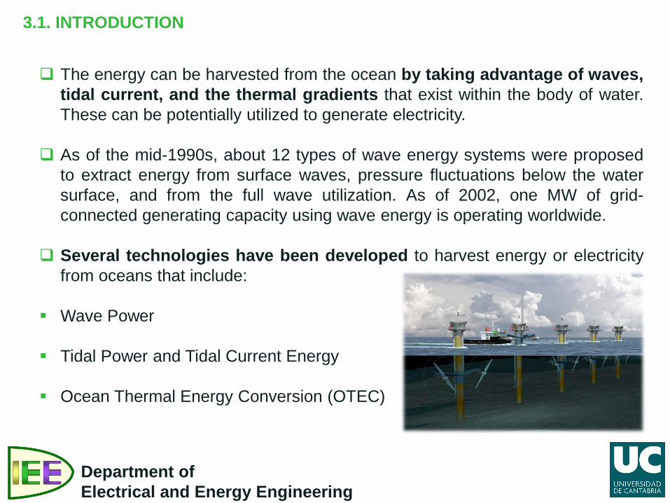
Several technologies have been developed to harvest energy or electricity from oceans that include:
Wave Power
Tidal Power and Tidal Current Energy
Ocean Thermal Energy Conversion (OTEC)
PART III. OCEAN ENERGY
3.1. Introduction.
3.2. Wave power. 3.3. Tidal power.
3.4. Ocean thermal energy.
Department of Electrical and Energy Engineering
3.2. WAVE POWER
Department of Electrical and Energy Engineering
Wind blowing over the surface of the ocean create waves that can be harvested for energy.
In several parts of the world, ocean waves are fairly consistent to produce energy on a continuous basis.
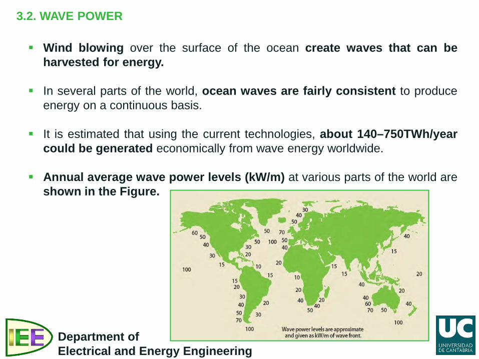
It is estimated that using the current technologies, about 140–750TWh/year could be generated economically from wave energy worldwide.
Annual average wave power levels (kW/m) at various parts of the world are shown in the Figure.
3.2. WAVE POWER
Department of Electrical and Energy Engineering
Very large energy fluxes can occur in deep water sea waves. The power in the wave is proportional to the square of the amplitude and to the period of the motion.
Therefore the long period (∼10 s), large amplitude (∼2m) waves have considerable interest for power generation, with energy fluxes commonly averaging between 50 and 70kW.m−1 width of oncoming wave.
There are many difficulties facing wave power developments: • Wave patterns are irregular in amplitude, phase and direction. It is
difficult to design devices to extract power efficiently over the wide range of variables.
• There is probability of extreme gales or hurricanes producing waves of freak intensity and the structure of the power devices must be able to withstand ∼100 times the power intensity to which they are matched.
• Wave periods are commonly ∼5–10 s (frequency ∼0.1Hz). It is extremely
difficult to couple this irregular slow motion to electrical generators requiring ∼500 times greater frequency.
3.2. WAVE POWER
Department of Electrical and Energy Engineering
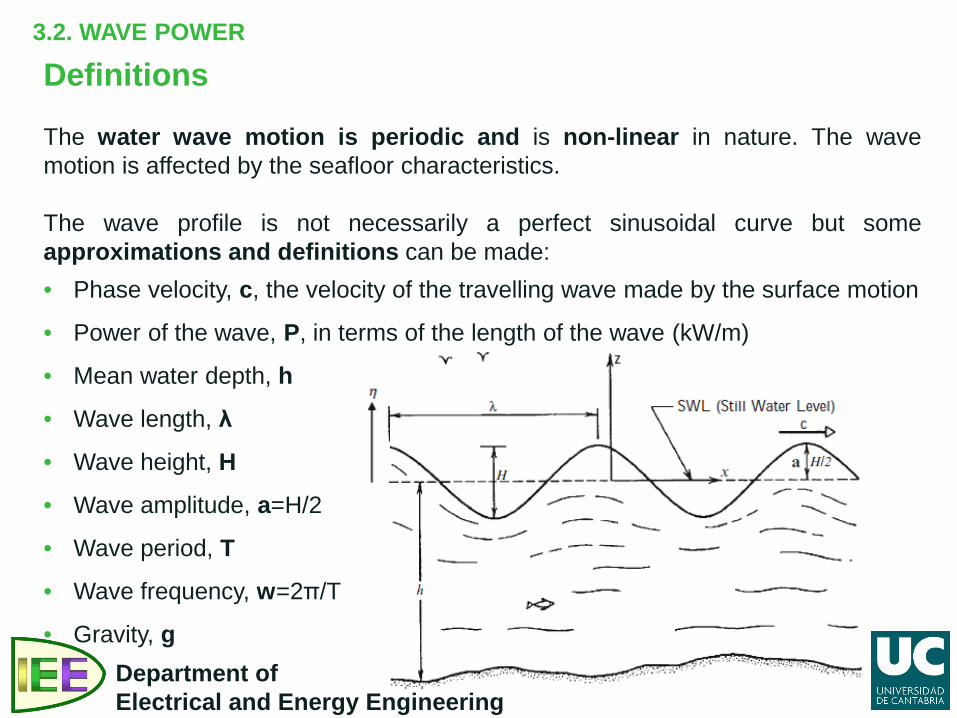
Definitions The water wave motion is periodic and is non-linear in nature. The wave motion is affected by the seafloor characteristics. The wave profile is not necessarily a perfect sinusoidal curve but some approximations and definitions can be made: • Phase velocity, c, the velocity of the travelling wave made by the surface motion
• Power of the wave, P, in terms of the length of the wave (kW/m)
• Mean water depth, h
• Wave length, λ
• Wave height, H
• Wave amplitude, a=H/2
• Wave period, T
• Wave frequency, w=2π/T
• Gravity, g
3.2. WAVE POWER
Department of Electrical and Energy Engineering
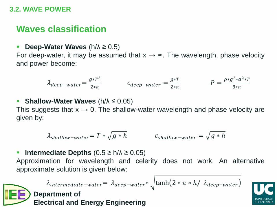
Waves classification Deep-Water Waves (h/λ ≥ 0.5) For deep-water, it may be assumed that x → ∞. The wavelength, phase velocity and power become:
𝜆𝑑𝑑𝑑𝑑−𝑤𝑤𝑤𝑑𝑤= 𝑔∗𝑇2
2∗𝜋 𝑐𝑑𝑑𝑑𝑑−𝑤𝑤𝑤𝑑𝑤 = 𝑔∗𝑇
2∗𝜋 𝑃 = 𝜌∗𝑔2∗𝑤2∗𝑇
8∗𝜋
Shallow-Water Waves (h/λ ≤ 0.05) This suggests that x → 0. The shallow-water wavelength and phase velocity are given by:
𝜆𝑠𝑠𝑤𝑠𝑠𝑠𝑤−𝑤𝑤𝑤𝑑𝑤= 𝑇 ∗ 𝑔 ∗ ℎ 𝑐𝑠𝑠𝑤𝑠𝑠𝑠𝑤−𝑤𝑤𝑤𝑑𝑤 = 𝑔 ∗ ℎ Intermediate Depths (0.5 ≥ h/λ ≥ 0.05) Approximation for wavelength and celerity does not work. An alternative approximate solution is given below:
𝜆𝑖𝑖𝑤𝑑𝑤𝑖𝑑𝑑𝑖𝑤𝑤𝑑−𝑤𝑤𝑤𝑑𝑤= 𝜆𝑑𝑑𝑑𝑑−𝑤𝑤𝑤𝑑𝑤∗ tanh 2 ∗ 𝜋 ∗ ℎ/ 𝜆𝑑𝑑𝑑𝑑−𝑤𝑤𝑤𝑑𝑤
3.2. WAVE POWER
Department of Electrical and Energy Engineering
Wave power systems Wave power systems can be installed near shore, offshore, or far
offshore. The design of the energy extraction systems depends on these locations.
In near shore systems, all the devices are within 20 km of the shore. Near shore operations have to consider how the plant will affect the aesthetic influence of the area. The impact on shipping lane and marine life also requires assessment.
A depth greater than 40–50 m will constitute an offshore operation. Even for an offshore operation, the preference is to install all the equipment and control systems at or near the water’s surface.
When installing energy extraction systems, the orientation of the turbines to the waves with which they are interacting should be taken into account. The electricity production depends heavily on these factors.
3.2. WAVE POWER
Department of Electrical and Energy Engineering
Wave power systems Five basic devices have been proposed or employed for electricity
generation from wave energy, and they are:
o Tapered Channel (TAPCHAN)
o Oscillating water column (OWC) o Point Absorber
o Attenuators
o Overtopping Devices
3.2. WAVE POWER
Department of Electrical and Energy Engineering
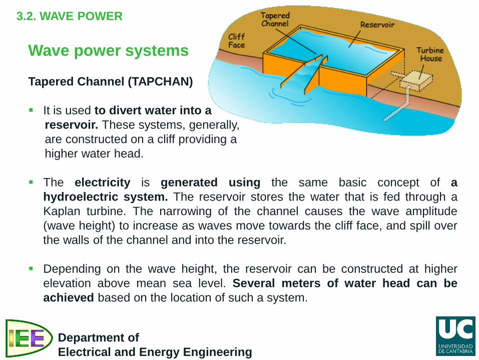
Wave power systems Tapered Channel (TAPCHAN) It is used to divert water into a reservoir. These systems, generally, are constructed on a cliff providing a higher water head.
The electricity is generated using the same basic concept of a
hydroelectric system. The reservoir stores the water that is fed through a Kaplan turbine. The narrowing of the channel causes the wave amplitude (wave height) to increase as waves move towards the cliff face, and spill over the walls of the channel and into the reservoir.
Depending on the wave height, the reservoir can be constructed at higher elevation above mean sea level. Several meters of water head can be achieved based on the location of such a system.
3.2. WAVE POWER
Department of Electrical and Energy Engineering
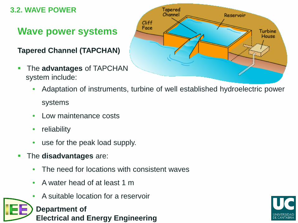
Wave power systems Tapered Channel (TAPCHAN) The advantages of TAPCHAN system include:
• Adaptation of instruments, turbine of well established hydroelectric power
systems
• Low maintenance costs
• reliability
• use for the peak load supply.
The disadvantages are:
• The need for locations with consistent waves
• A water head of at least 1 m
• A suitable location for a reservoir
3.2. WAVE POWER
Department of Electrical and Energy Engineering
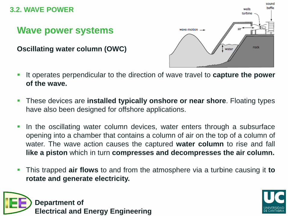
Wave power systems Oscillating water column (OWC)
It operates perpendicular to the direction of wave travel to capture the power
of the wave.
These devices are installed typically onshore or near shore. Floating types have also been designed for offshore applications.
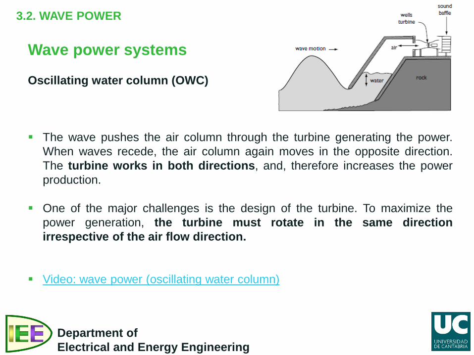
In the oscillating water column devices, water enters through a subsurface opening into a chamber that contains a column of air on the top of a column of water. The wave action causes the captured water column to rise and fall like a piston which in turn compresses and decompresses the air column.
This trapped air flows to and from the atmosphere via a turbine causing it to rotate and generate electricity.
3.2. WAVE POWER
Department of Electrical and Energy Engineering
Wave power systems Oscillating water column (OWC)
The wave pushes the air column through the turbine generating the power. When waves recede, the air column again moves in the opposite direction. The turbine works in both directions, and, therefore increases the power production.
One of the major challenges is the design of the turbine. To maximize the power generation, the turbine must rotate in the same direction irrespective of the air flow direction.
Video: wave power (oscillating water column)
3.2. WAVE POWER
Department of Electrical and Energy Engineering
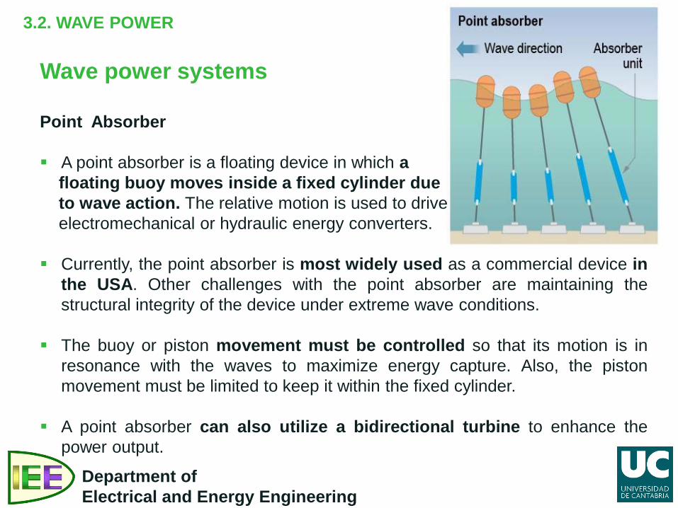
Wave power systems Point Absorber A point absorber is a floating device in which a floating buoy moves inside a fixed cylinder due to wave action. The relative motion is used to drive electromechanical or hydraulic energy converters.
Currently, the point absorber is most widely used as a commercial device in
the USA. Other challenges with the point absorber are maintaining the structural integrity of the device under extreme wave conditions.
The buoy or piston movement must be controlled so that its motion is in resonance with the waves to maximize energy capture. Also, the piston movement must be limited to keep it within the fixed cylinder.
A point absorber can also utilize a bidirectional turbine to enhance the
power output.
3.2. WAVE POWER
Department of Electrical and Energy Engineering
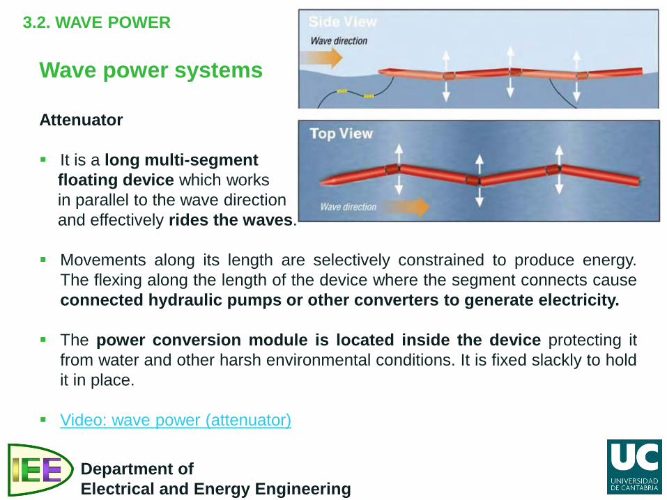
Wave power systems Attenuator It is a long multi-segment floating device which works in parallel to the wave direction and effectively rides the waves.
Movements along its length are selectively constrained to produce energy.
The flexing along the length of the device where the segment connects cause connected hydraulic pumps or other converters to generate electricity.
The power conversion module is located inside the device protecting it
from water and other harsh environmental conditions. It is fixed slackly to hold it in place.
Video: wave power (attenuator)
3.2. WAVE POWER
Department of Electrical and Energy Engineering
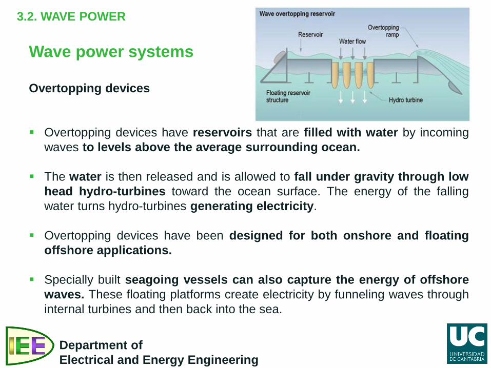
Wave power systems Overtopping devices Overtopping devices have reservoirs that are filled with water by incoming
waves to levels above the average surrounding ocean. The water is then released and is allowed to fall under gravity through low
head hydro-turbines toward the ocean surface. The energy of the falling water turns hydro-turbines generating electricity.
Overtopping devices have been designed for both onshore and floating
offshore applications.
Specially built seagoing vessels can also capture the energy of offshore waves. These floating platforms create electricity by funneling waves through internal turbines and then back into the sea.
PART III. OCEAN ENERGY
3.1. Introduction.
3.2. Wave power. 3.3. Tidal power.
3.4. Ocean thermal energy.
Department of Electrical and Energy Engineering
3.3. TIDAL POWER
Department of Electrical and Energy Engineering
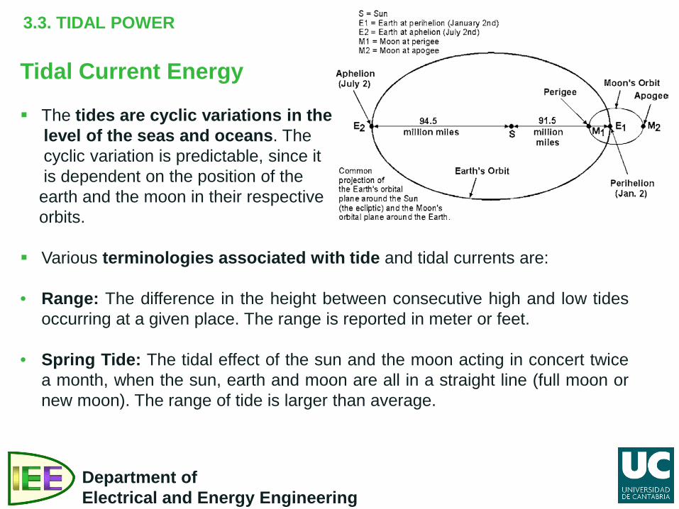
Tidal Current Energy The tides are cyclic variations in the level of the seas and oceans. The cyclic variation is predictable, since it is dependent on the position of the earth and the moon in their respective orbits.
Various terminologies associated with tide and tidal currents are:
• Range: The difference in the height between consecutive high and low tides
occurring at a given place. The range is reported in meter or feet.
• Spring Tide: The tidal effect of the sun and the moon acting in concert twice a month, when the sun, earth and moon are all in a straight line (full moon or new moon). The range of tide is larger than average.
3.3. TIDAL POWER
Department of Electrical and Energy Engineering
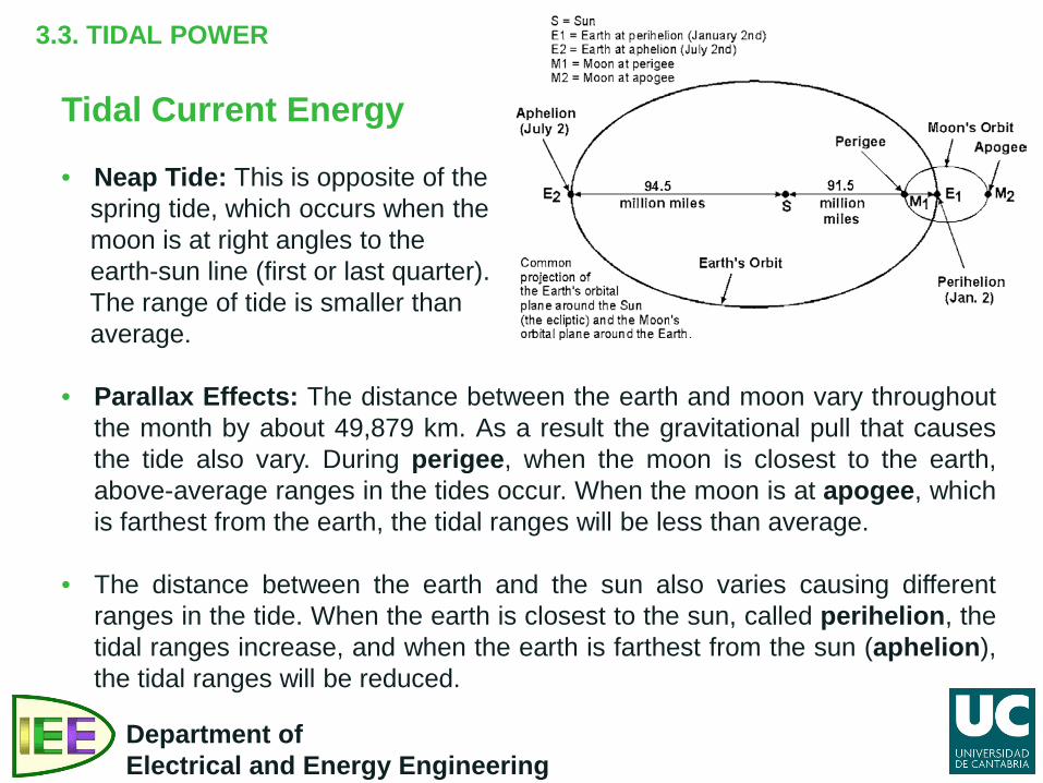
Tidal Current Energy • Neap Tide: This is opposite of the spring tide, which occurs when the moon is at right angles to the earth-sun line (first or last quarter). The range of tide is smaller than average.
• Parallax Effects: The distance between the earth and moon vary throughout
the month by about 49,879 km. As a result the gravitational pull that causes the tide also vary. During perigee, when the moon is closest to the earth, above-average ranges in the tides occur. When the moon is at apogee, which is farthest from the earth, the tidal ranges will be less than average.
• The distance between the earth and the sun also varies causing different
ranges in the tide. When the earth is closest to the sun, called perihelion, the tidal ranges increase, and when the earth is farthest from the sun (aphelion), the tidal ranges will be reduced.
3.3. TIDAL POWER
Department of Electrical and Energy Engineering
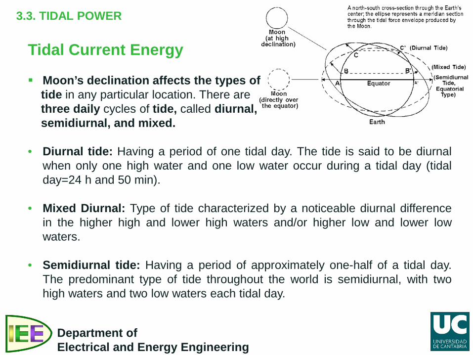
Tidal Current Energy Moon’s declination affects the types of tide in any particular location. There are three daily cycles of tide, called diurnal, semidiurnal, and mixed. • Diurnal tide: Having a period of one tidal day. The tide is said to be diurnal
when only one high water and one low water occur during a tidal day (tidal day=24 h and 50 min).
• Mixed Diurnal: Type of tide characterized by a noticeable diurnal difference in the higher high and lower high waters and/or higher low and lower low waters.
• Semidiurnal tide: Having a period of approximately one-half of a tidal day. The predominant type of tide throughout the world is semidiurnal, with two high waters and two low waters each tidal day.
3.3. TIDAL POWER
Department of Electrical and Energy Engineering
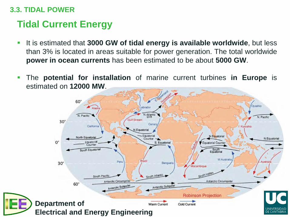
Tidal Current Energy It is estimated that 3000 GW of tidal energy is available worldwide, but less
than 3% is located in areas suitable for power generation. The total worldwide power in ocean currents has been estimated to be about 5000 GW.
The potential for installation of marine current turbines in Europe is estimated on 12000 MW.
3.3. TIDAL POWER
Department of Electrical and Energy Engineering
Tidal Power Technologies Tidal power technologies may be categorized into two groups as follows:
• Tidal Barrage or Dam Method • Tidal Turbine Method
Tidal Barrage Method A barrage or dam is typically used to force the water during high tide into a
reservoir. When the tides produce an adequate difference in the level of the water on the opposite side of the dam, the gates are opened.
The water is allowed to flow through a low head turbine, in a similar manner as a hydroelectric system. Gates and turbines are installed along the dam. The turbines turn an electric generator to produce electricity.
There are currently two commercial barrages in operations. One is located in La Rance, France and the other one is in Annapolis Royal, Nova Scotia, Canada.
3.3. TIDAL POWER
Department of Electrical and Energy Engineering
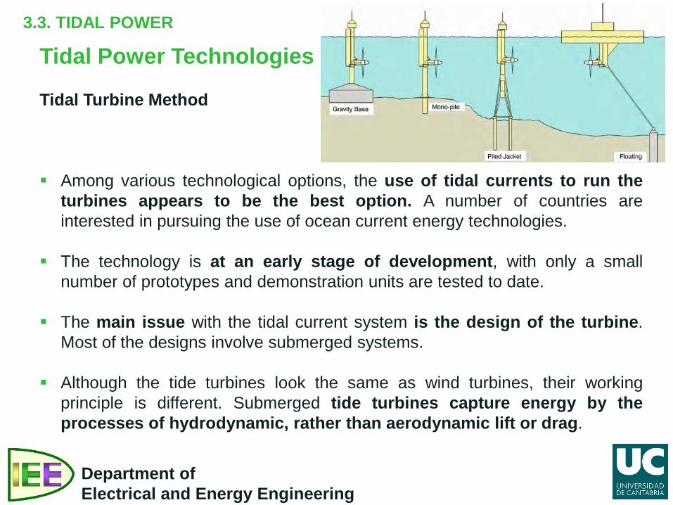
Tidal Power Technologies Tidal Turbine Method Among various technological options, the use of tidal currents to run the
turbines appears to be the best option. A number of countries are interested in pursuing the use of ocean current energy technologies.
The technology is at an early stage of development, with only a small number of prototypes and demonstration units are tested to date.
The main issue with the tidal current system is the design of the turbine. Most of the designs involve submerged systems.
Although the tide turbines look the same as wind turbines, their working principle is different. Submerged tide turbines capture energy by the processes of hydrodynamic, rather than aerodynamic lift or drag.
3.3. TIDAL POWER
Department of Electrical and Energy Engineering
Tidal Power Technologies Tidal Turbine Method These turbines have rotor blades, a generator for converting the rotational
energy into electricity, and a means for transporting the electrical current to shore for incorporation into the electrical grid.
Four types of turbine have been explored for generating electricity from the tidal current, and these include:
• Horizontal Axis Turbines: Similar to wind turbines. The power output depends
on the rotor diameter and the stream flow rate and can be controlled using pitch controlled blades.
Video: Tidal Horizontal Turbine. • Vertical Axis Turbines: In vertical axis turbines, water stream flow is
perpendicular to the rotational axis of the turbine. Several vertical axis turbines have been designed for their feasibility in commercial applications.
Video: Tidal Vertical Turbine.
3.3. TIDAL POWER
Department of Electrical and Energy Engineering
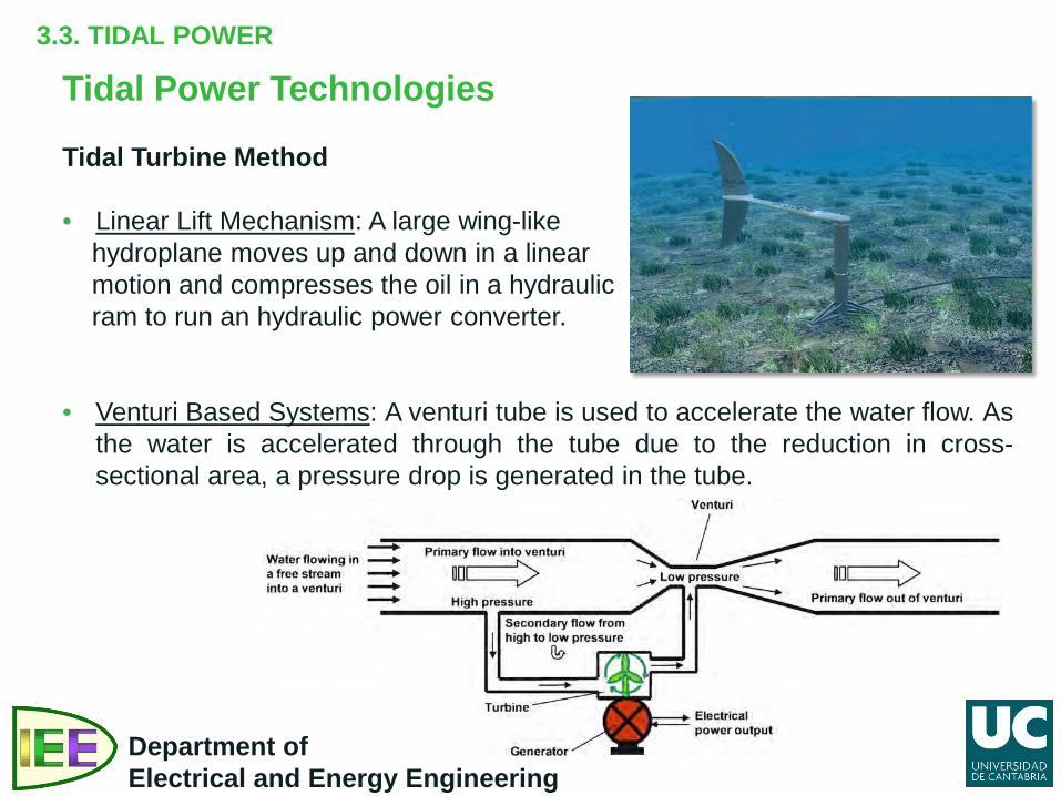
Tidal Power Technologies Tidal Turbine Method • Linear Lift Mechanism: A large wing-like hydroplane moves up and down in a linear motion and compresses the oil in a hydraulic ram to run an hydraulic power converter. • Venturi Based Systems: A venturi tube is used to accelerate the water flow. As
the water is accelerated through the tube due to the reduction in cross-sectional area, a pressure drop is generated in the tube.
PART III. OCEAN ENERGY
3.1. Introduction.
3.2. Wave power. 3.3. Tidal power.
3.4. Ocean thermal energy.
Department of Electrical and Energy Engineering
3.4. OCEAN THERMAL ENERGY
Department of Electrical and Energy Engineering
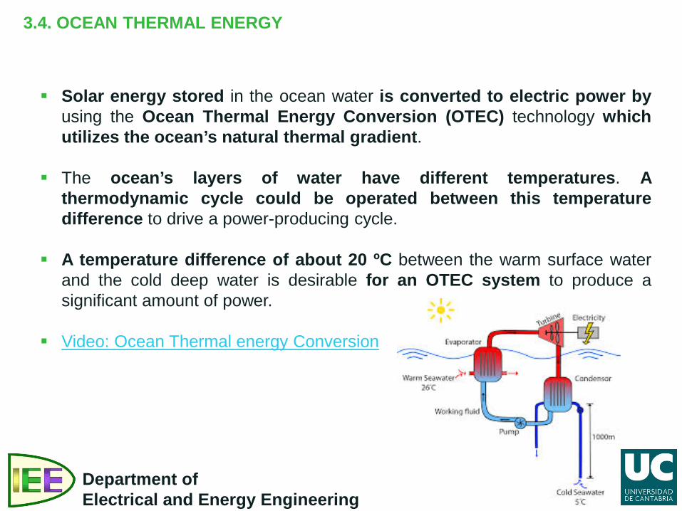
Solar energy stored in the ocean water is converted to electric power by using the Ocean Thermal Energy Conversion (OTEC) technology which utilizes the ocean’s natural thermal gradient.
The ocean’s layers of water have different temperatures. A thermodynamic cycle could be operated between this temperature difference to drive a power-producing cycle.
A temperature difference of about 20 ºC between the warm surface water and the cold deep water is desirable for an OTEC system to produce a significant amount of power.
Video: Ocean Thermal energy Conversion
3.4. OCEAN THERMAL ENERGY
Department of Electrical and Energy Engineering
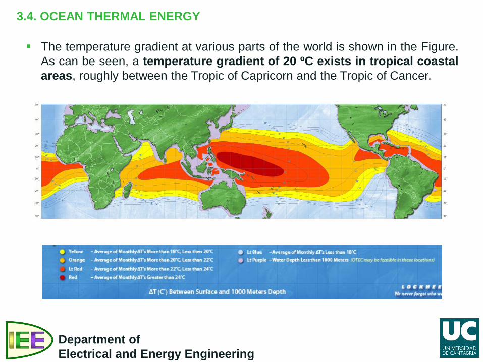
The temperature gradient at various parts of the world is shown in the Figure. As can be seen, a temperature gradient of 20 ºC exists in tropical coastal areas, roughly between the Tropic of Capricorn and the Tropic of Cancer.
3.4. OCEAN THERMAL ENERGY
Department of Electrical and Energy Engineering
Ocean thermal generation has the following advantages and disadvantages. Advantages: • The energy is free – no fuel is needed and no waste is produced • Not expensive to operate and maintain • Can produce a significant amount of energy
Disadvantages: • Variable energy supply but more consistent than wind or solar energy • Needs a suitable site, where waves or currents are consistently strong • Must be able to withstand very rough weather • Costly to develop • Visual impact if turbines are above water or on shore • Can disturb or disrupt marine life – including changes in the distribution and
types of marine life near the shore • Poses a possible threat to navigation from collisions • May interfere with mooring and anchorage lines with commercial fishing • May degrade scenic ocean front views from wave energy devices located
near or on the shore, and from onshore overhead electric transmission lines
3.4. OCEAN THERMAL ENERGY
Department of Electrical and Energy Engineering
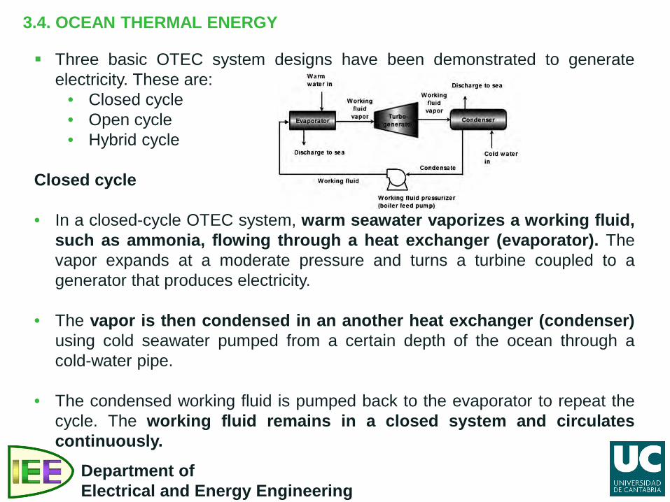
Three basic OTEC system designs have been demonstrated to generate electricity. These are:
• Closed cycle • Open cycle • Hybrid cycle
Closed cycle • In a closed-cycle OTEC system, warm seawater vaporizes a working fluid,
such as ammonia, flowing through a heat exchanger (evaporator). The vapor expands at a moderate pressure and turns a turbine coupled to a generator that produces electricity.
• The vapor is then condensed in an another heat exchanger (condenser) using cold seawater pumped from a certain depth of the ocean through a cold-water pipe.
• The condensed working fluid is pumped back to the evaporator to repeat the cycle. The working fluid remains in a closed system and circulates continuously.
3.4. OCEAN THERMAL ENERGY
Department of Electrical and Energy Engineering
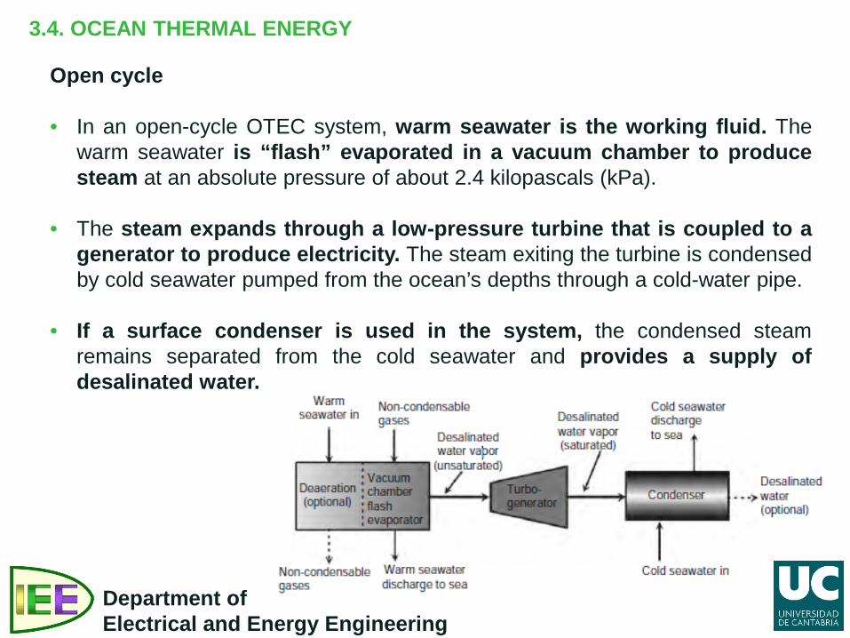
Open cycle • In an open-cycle OTEC system, warm seawater is the working fluid. The
warm seawater is “flash” evaporated in a vacuum chamber to produce steam at an absolute pressure of about 2.4 kilopascals (kPa).
• The steam expands through a low-pressure turbine that is coupled to a generator to produce electricity. The steam exiting the turbine is condensed by cold seawater pumped from the ocean’s depths through a cold-water pipe.
• If a surface condenser is used in the system, the condensed steam remains separated from the cold seawater and provides a supply of desalinated water.
3.4. OCEAN THERMAL ENERGY
Department of Electrical and Energy Engineering
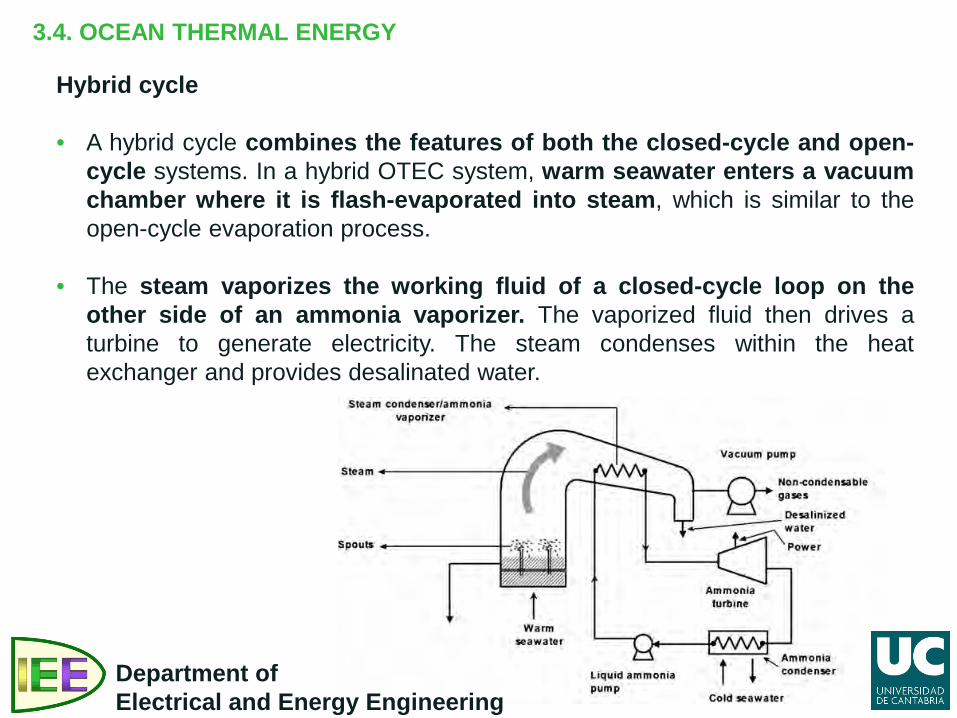
Hybrid cycle • A hybrid cycle combines the features of both the closed-cycle and open-
cycle systems. In a hybrid OTEC system, warm seawater enters a vacuum chamber where it is flash-evaporated into steam, which is similar to the open-cycle evaporation process.
• The steam vaporizes the working fluid of a closed-cycle loop on the other side of an ammonia vaporizer. The vaporized fluid then drives a turbine to generate electricity. The steam condenses within the heat exchanger and provides desalinated water.
SOURCES: Twidell, John; Weir, Tony. Renewable Energy Resources (2006). Taylor &
Francis. Tushar K. Ghosh; Mark A. Prelas. Energy Resources and Systems. Volume 2:
Renewable Resources. (2011). Springer. Paul Breeze; Aldo Vieira et all. Renewable Energy Focus Handbook. (2009).
Elsevier.
Department of Electrical and Energy Engineering