renault megane service manual
DESCRIPTION
Service and reparation tips for Renault MeganeTRANSCRIPT
77 11 176 201 APRIL 1995 Edition Anglaise
General
"The repair methods given by the manufacturer in this document are based on thetechnical specifications current when it was prepared.
The methods may be modified as a result of changes introduced by themanufacturer in the production of the various component units and accessoriesfrom which his vehicles are constructed."
All copyrights reserved by the Regie Nationale des Usines Renault.
Copying or translating, in part or in full, of this document or use of the service partreference numbering system is forbidden without the prior written authority of theRegie Nationale des Usines Renault.
Régie Nationale des Usines Renault S.A. 1995
SPECIFICATIONS
LIFTING
TOWING
LUBRICANTS CONSUMABLES
DRAINING, RE-FILLING
BA0A - BA0E - BA0F - BA0G - BA0L - BA0U
C
VALUES AND SETTINGS
SECTION VIEW
TOWING
All types
Contents
SPECIFICATIONS
Engine - Clutch - GearboxVehicle identification
01-101-2
LIFTING
Trolley jack - Axle standsVehicle lifts
Page
01
02
03
General
02-102-2
03-1
LUBRICANTS - CONSUMABLES
Packaging 04-1
DRAINING, RE-FILLING
EngineGearboxPower assisted steering
04
05
05-105-305-4
VALUES AND SETTINGS
DimensionsCapacity - GradesBelt tensionAccessories belt tensionTiming belt tensionTightening the cylinder headDimensions of the main brakingcomponentsValues for checking the front axlegeometryValues for checking the rear axlegeometryUnderbody heightsBrake limiter
07
07-107-207-507-7
07-1307-15
07-17
07-18
07-2107-2207-23

SPECIFICATIONSEngine- Clutch - Gearbox 01
Vehicle type
Engine
Type Capacity
Clutch typeType of manual gearbox and
automatic transmission
BA0E E7J 1390 180 DST 3050180 CP 3300 JB1
BA0FBA0L K7M 1598 200 HR 4000 JB1
BA0G F3R 1998 215 HRN 4000 JB3
BA0ABA0U F8Q 1870 200 HRV 4600
200 HRV 3100 JB1
BA0F K7M 1598 - AD4
VEHICLE IDENTIFICATION
Example : BA0E
B : Body type (example 5 door hatchback)A : Project code (example 64)0E : Engine suffix (example E7J 764)
01-1
SPECIFICATIONSVehicle identification
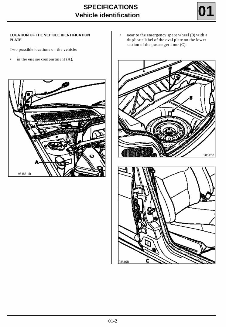
• near to the emergency spare wheel (B) with aduplicate label of the oval plate on the lowersection of the passenger door (C).
01LOCATION OF THE VEHICLE IDENTIFICATIONPLATE
Two possible locations on the vehicle:
• in the engine compartment (A),
98485-1R
98517R
98516R
01-2
SPECIFICATIONSVehicle identification 01
REGIE NATIONALE DES
USINES RENAULT S.A.
e000-00/00000-0000-00
VF0000000
00000000
0000 kg
0000 kg
1 - 0000 kg
2 - 0000 kg
100 0 0 0
0 0 0 0 0 0 0 0
0 0 0 0 0 0 0
11
0 0 0 0 0 0 0 0
7
13
8
14
9
12
Renault
1
2
3
4
5
6
VF0000000
00000000
0000
00 000 000
00 000 000
0000000
9
10
12
11
1
2
8
7
14
13
B
A
01-3
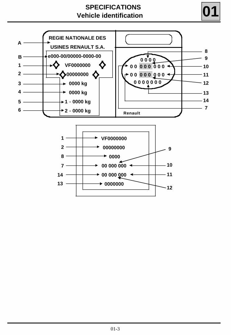
SPECIFICATIONSVehicle identification 01
It shows:At A : the name of the manufacturer,At B : the E.E.C. approval number At 1 : the type mines of the vehicle preceded by the world manufacturers identification code (VF1 corre-
sponds to RENAULT FRANCE),At 2 : the chassis number,At 3 : the maximum permissible weight,At 4 : the maximum permitted total train weight,At 5 : the maximum permitted weight on the front axle,At 6 : the maximum permitted weight on the rear axle,At 7 : the first figure indicates the gearbox or factory options,
the second figure indicates the equipment level,At 8 : the vehicle type,At 9 : the technical equipment code,At 10 : additional factory optional equipment,At 11 : the equipment level,At 12 : the paint code,At 13 : a letter describing the factory of manufacture followed by the fabrication number,At 14 : the trim code.
NOTE : Depending on the country of export, certain details might not be given. The plate described aboveshows all possible information.
ALLOCATION OF TECHNICAL EQUIPMENT CODES
The equipment code, the three letters which appear in (9), must be documented for vehicle identificationreasons (ordering spare parts, warranty claim, etc.)
01-4
LIFTINGTrolley jack - Axle stands
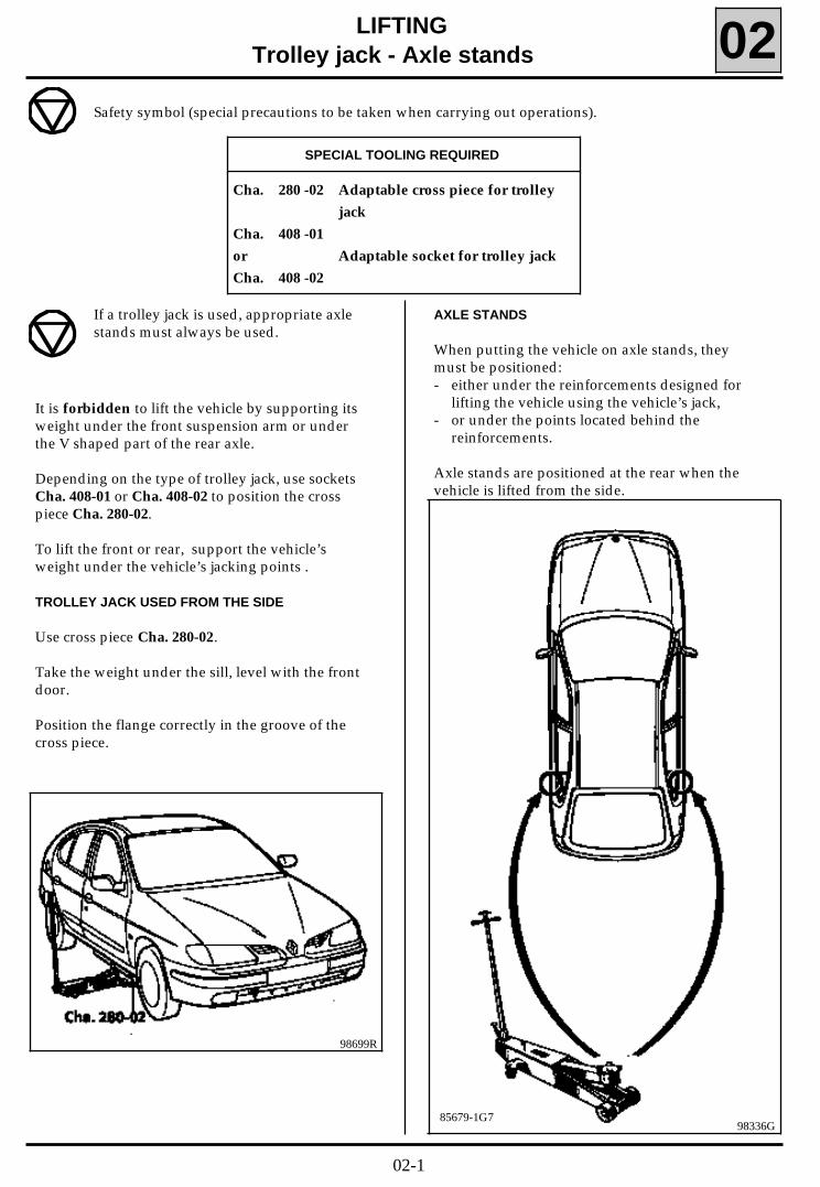
AXLE STANDS
When putting the vehicle on axle stands, theymust be positioned: - either under the reinforcements designed for
lifting the vehicle using the vehicle’s jack,- or under the points located behind the
reinforcements.
Axle stands are positioned at the rear when thevehicle is lifted from the side.
02
98699R
Safety symbol (special precautions to be taken when carrying out operations).
SPECIAL TOOLING REQUIRED
Cha. 280 -02 Adaptable cross piece for trolley
jack
Cha. 408 -01
or Adaptable socket for trolley jack
Cha. 408 -02
If a trolley jack is used, appropriate axlestands must always be used.
It is forbidden to lift the vehicle by supporting itsweight under the front suspension arm or underthe V shaped part of the rear axle.
Depending on the type of trolley jack, use socketsCha. 408-01 or Cha. 408-02 to position the crosspiece Cha. 280-02.
To lift the front or rear, support the vehicle’sweight under the vehicle’s jacking points .
TROLLEY JACK USED FROM THE SIDE
Use cross piece Cha. 280-02.
Take the weight under the sill, level with the frontdoor.
Position the flange correctly in the groove of thecross piece.
98336G85679-1G7
02-1
LIFTINGVehicle lifts 02
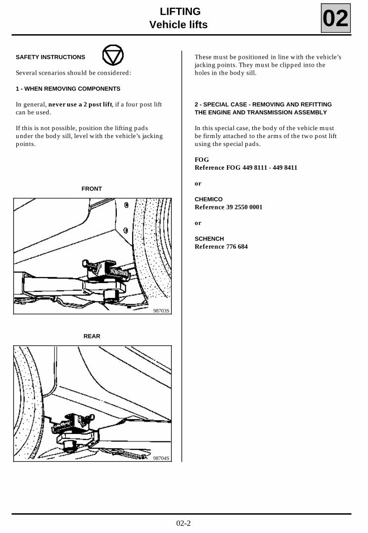
SAFETY INSTRUCTIONS
Several scenarios should be considered:
1 - WHEN REMOVING COMPONENTS
In general, never use a 2 post lift, if a four post liftcan be used.
If this is not possible, position the lifting padsunder the body sill, level with the vehicle’s jackingpoints.
2 - SPECIAL CASE - REMOVING AND REFITTINGTHE ENGINE AND TRANSMISSION ASSEMBLY
In this special case, the body of the vehicle mustbe firmly attached to the arms of the two post liftusing the special pads.
FOGReference FOG 449 8111 - 449 8411
or
CHEMICOReference 39 2550 0001
or
SCHENCHReference 776 684
98703S
FRONT
98704S
REAR
These must be positioned in line with the vehicle’sjacking points. They must be clipped into theholes in the body sill.
02-2
TOWING
All types
FRONT
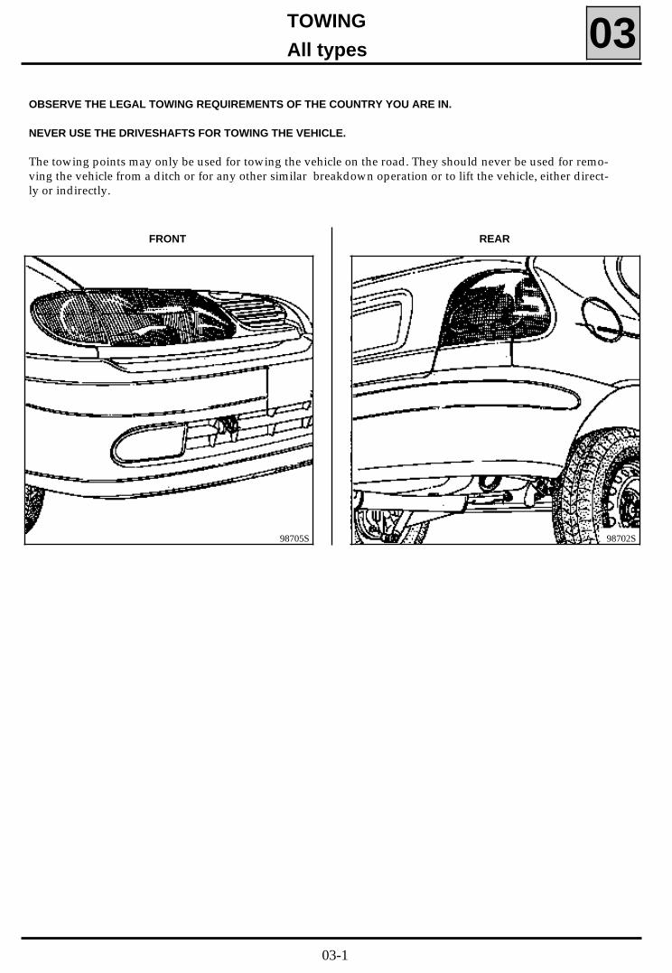
03OBSERVE THE LEGAL TOWING REQUIREMENTS OF THE COUNTRY YOU ARE IN.
NEVER USE THE DRIVESHAFTS FOR TOWING THE VEHICLE.
The towing points may only be used for towing the vehicle on the road. They should never be used for remo-ving the vehicle from a ditch or for any other similar breakdown operation or to lift the vehicle, either direct-ly or indirectly.
98705S
REAR
98702S
03-1
DESCRIPTION PACKAGING PART NUMBER
1 kg tin
100 g tube
80 ml tube
180 g sachet
Aerosol
77 01 421 145
77 01 028 179
77 01 422 307
77 01 366 100
77 01 422 308
LUBRICANTS
LUBRICANTS - CONSUMABLESPackaging 04
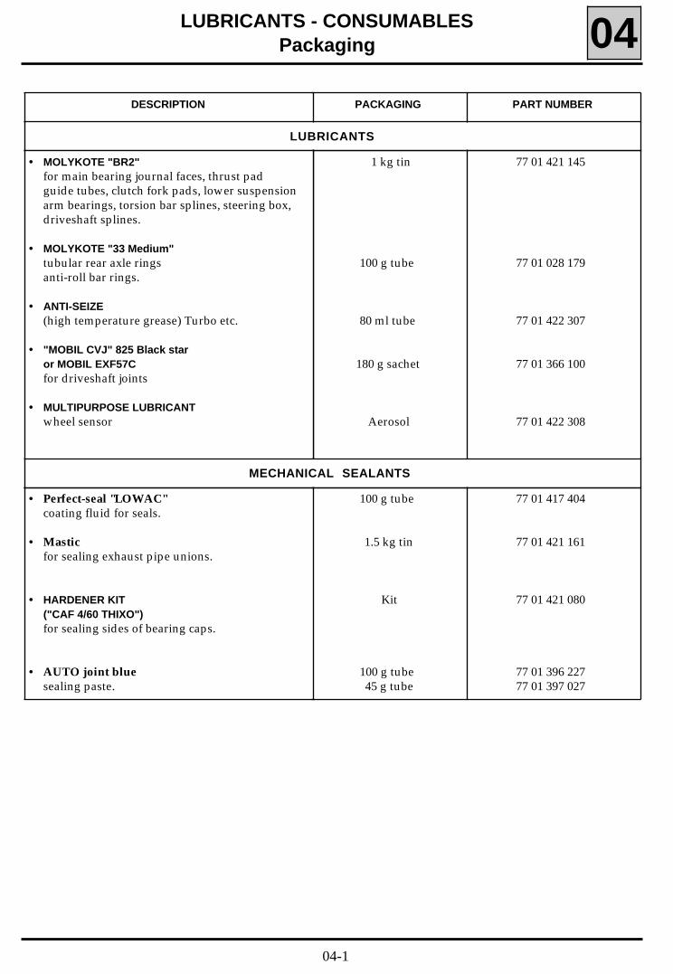
• MOLYKOTE "BR2"for main bearing journal faces, thrust padguide tubes, clutch fork pads, lower suspensionarm bearings, torsion bar splines, steering box,driveshaft splines.
• MOLYKOTE "33 Medium"tubular rear axle ringsanti-roll bar rings.
• ANTI-SEIZE(high temperature grease) Turbo etc.
• "MOBIL CVJ" 825 Black staror MOBIL EXF57Cfor driveshaft joints
• MULTIPURPOSE LUBRICANTwheel sensor
• Perfect-seal "LOWAC"coating fluid for seals.
• Mastic for sealing exhaust pipe unions.
• HARDENER KIT("CAF 4/60 THIXO")for sealing sides of bearing caps.
• AUTO joint bluesealing paste.
100 g tube
1.5 kg tin
Kit
100 g tube 45 g tube
77 01 417 404
77 01 421 161
77 01 421 080
77 01 396 22777 01 397 027
MECHANICAL SEALANTS
04-1
DESCRIPTION PACKAGING PART NUMBER
24 cc bottle
24 cc bottle
24 cc bottle
50 cc bottle
77 01 394 070
77 01 394 071
77 01 394 072
77 01 400 309
ADHESIVES
LUBRICANTS - CONSUMABLESPackaging 04
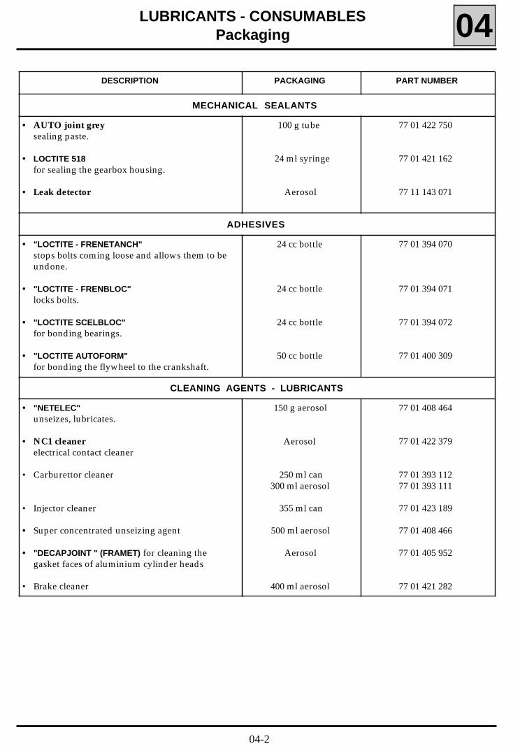
• "LOCTITE - FRENETANCH"stops bolts coming loose and allows them to beundone.
• "LOCTITE - FRENBLOC"locks bolts.
• "LOCTITE SCELBLOC"for bonding bearings.
• "LOCTITE AUTOFORM"for bonding the flywheel to the crankshaft.
CLEANING AGENTS - LUBRICANTS
150 g aerosol
Aerosol
250 ml can300 ml aerosol
355 ml can
500 ml aerosol
Aerosol
400 ml aerosol
77 01 408 464
77 01 422 379
77 01 393 11277 01 393 111
77 01 423 189
77 01 408 466
77 01 405 952
77 01 421 282
• "NETELEC"unseizes, lubricates.
• NC1 cleanerelectrical contact cleaner
• Carburettor cleaner
• Injector cleaner
• Super concentrated unseizing agent
• "DECAPJOINT " (FRAMET) for cleaning thegasket faces of aluminium cylinder heads
• Brake cleaner
MECHANICAL SEALANTS
• AUTO joint greysealing paste.
• LOCTITE 518for sealing the gearbox housing.
• Leak detector
100 g tube
24 ml syringe
Aerosol
77 01 422 750
77 01 421 162
77 11 143 071
04-2
DESCRIPTION PACKAGING PART NUMBER
LUBRICANTS - CONSUMABLESPackaging 04
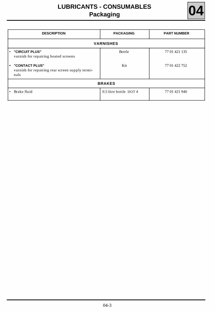
• "CIRCUIT PLUS"varnish for repairing heated screens
• "CONTACT PLUS"varnish for repairing rear screen supply termi-nals
Bottle
Kit
77 01 421 135
77 01 422 752
VARNISHES
BRAKES
• Brake fluid 0.5 litre bottle DOT 4 77 01 421 940
04-3
DRAINING, RE-FILLINGEngine
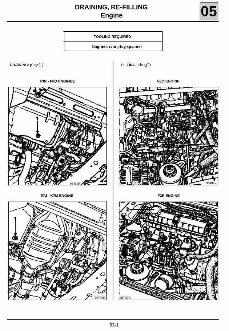
E7J - K7M ENGINE
05
F3R - F8Q ENGINES
98486R
TOOLING REQUIRED
Engine drain plug spanner
DRAINING: plug(1)
98701R
FILLING: plug(2)
F3R ENGINE
F8Q ENGINE
98487R
98489R
05-1
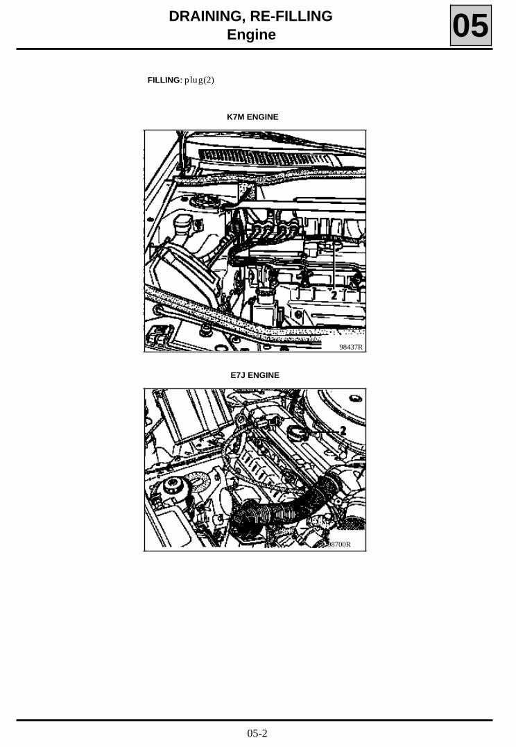
DRAINING, RE-FILLINGEngine 05
FILLING: plug(2)
E7J ENGINE
K7M ENGINE
98700R
98437R
05-2
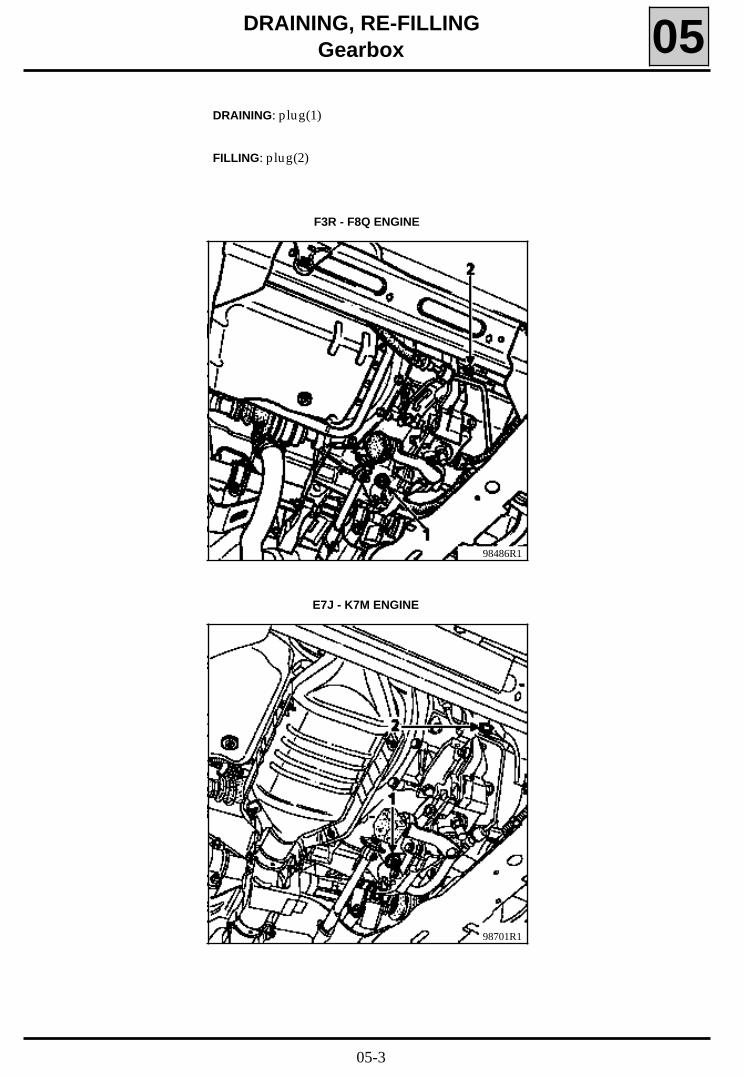
DRAINING, RE-FILLINGGearbox 05
DRAINING: plug(1)
F3R - F8Q ENGINE
FILLING: plug(2)
98486R1
E7J - K7M ENGINE
98701R1
05-3
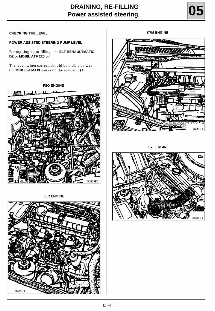
DRAINING, RE-FILLINGPower assisted steering 05
CHECKING THE LEVEL
POWER ASSISTED STEERING PUMP LEVEL
For topping up or filling, use ELF RENAULTMATICD2 or MOBIL ATF 220 oil.
The level, when correct, should be visible betweenthe MINI and MAXI marks on the reservoir (1).
98489R1
98487R1
F8Q ENGINE
F3R ENGINE
98437R1
K7M ENGINE
98700R1
E7J ENGINE
05-4
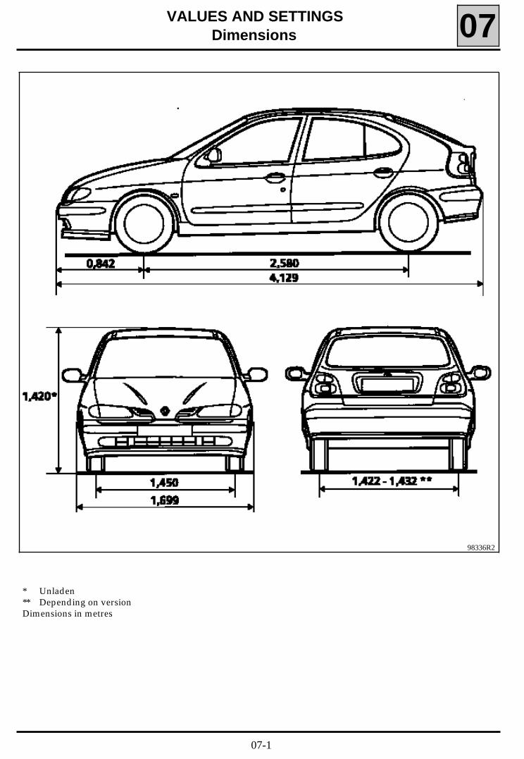
VALUES AND SETTINGSDimensions
* Unladen** Depending on versionDimensions in metres
07
98336R2
07-1
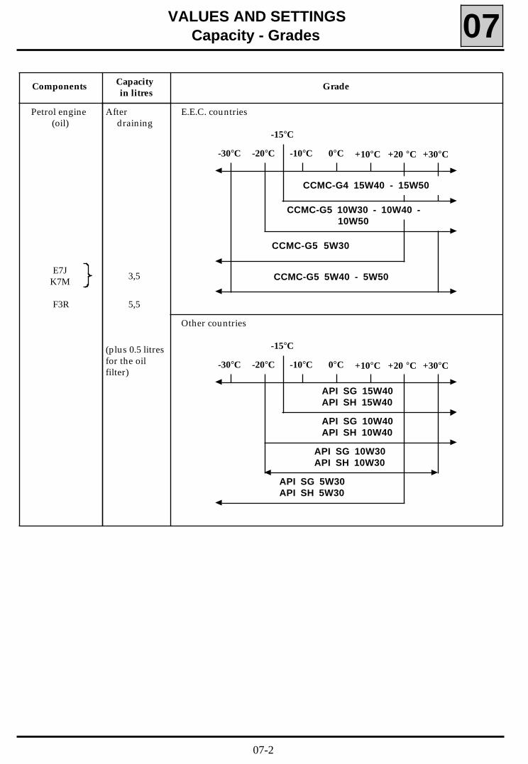
API SG 5W30API SH 5W30
API SG 10W40API SH 10W40
API SG 15W40API SH 15W40
VALUES AND SETTINGSCapacity - Grades 07
Components
Afterdraining
3,5
5,5
(plus 0.5 litresfor the oilfilter)
E.E.C. countries
Other countries
Capacity in litres
Grade
Petrol engine(oil)
E7JK7M
F3R
0°C +30°C-30°C +10°C +20 °C-20°C -10°C
-15°C
CCMC-G5 10W30 - 10W40 -10W50
CCMC-G5 5W40 - 5W50
CCMC-G5 5W30
CCMC-G4 15W40 - 15W50
API SG 10W30API SH 10W30
0°C +30°C-30°C +10°C +20 °C-20°C -10°C
-15°C
07-2
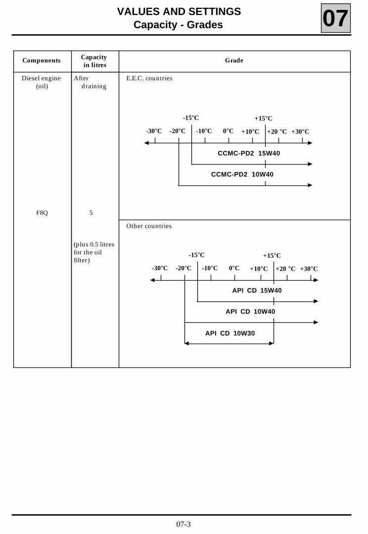
VALUES AND SETTINGSCapacity - Grades 07
Components
Afterdraining
5
(plus 0.5 litresfor the oilfilter)
E.E.C. countries
Other countries
Capacity in litres
Grade
Diesel engine(oil)
F8Q
0°C +30°C-30°C +10°C +20 °C-20°C -10°C
-15°C +15°C
CCMC-PD2 15W40
CCMC-PD2 10W40
API CD 10W30
0°C +30°C-30°C +10°C +20 °C-20°C -10°C
-15°C +15°C
API CD 15W40
API CD 10W40
07-3

AD4 4ELF RENAULT MATIC D2 (D20104)or use: MOBIL ATF 220 (D20104 or D21412)
TEXAMATIC 4011
Automatictransmission
VALUES AND SETTINGSCapacity - Grades 07
3 .4
Manual gearbox
Components Capacity inlitres
Grade Features
JB1 3 .4
Brake circuit Brake fluids must be approved by the TechnicalDepartment
SAE J 1703and DOT 3
All countries: TRANSELF TRX 75 W 80 W( API GL5 or MIL-L 2105 C or D standards)
Normal : 0.7ABS : 1
Fuel tank approximately60
Unleadedpetrol/diesel
JB3
Separatereservoir
1.1
Cooling circuit
F3R
F8Q
E7J - K7M
GLACÉOL RX(type D)
Only add coolant7
7 .5
6
Power assistedsteering
ELF RENAULT MATICD2 or
MOBIL ATF 220
07-4
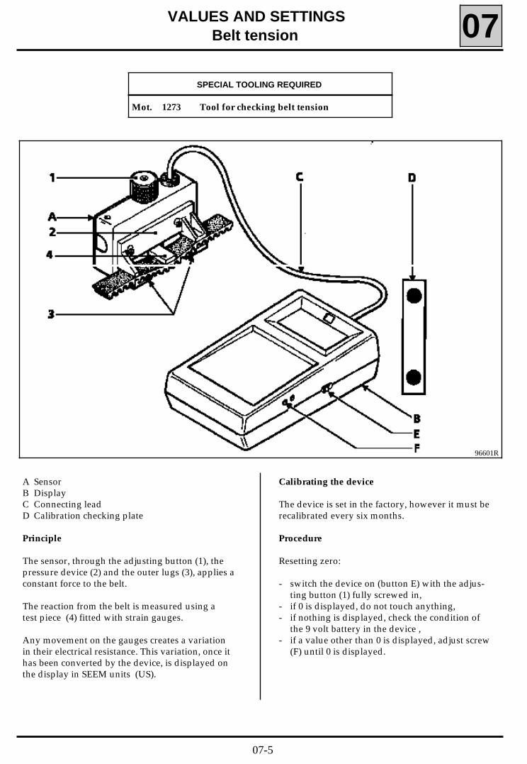
VALUES AND SETTINGSBelt tension 07
96601R
SPECIAL TOOLING REQUIRED
Mot. 1273 Tool for checking belt tension
A SensorB DisplayC Connecting leadD Calibration checking plate
Principle
The sensor, through the adjusting button (1), thepressure device (2) and the outer lugs (3), applies aconstant force to the belt.
The reaction from the belt is measured using atest piece (4) fitted with strain gauges.
Any movement on the gauges creates a variationin their electrical resistance. This variation, once ithas been converted by the device, is displayed onthe display in SEEM units (US).
Calibrating the device
The device is set in the factory, however it must berecalibrated every six months.
Procedure
Resetting zero:
- switch the device on (button E) with the adjus-ting button (1) fully screwed in,
- if 0 is displayed, do not touch anything,- if nothing is displayed, check the condition of
the 9 volt battery in the device ,- if a value other than 0 is displayed, adjust screw
(F) until 0 is displayed.
07-5
VALUES AND SETTINGSBelt tension 07
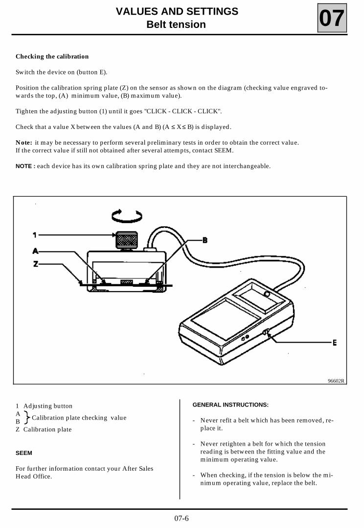
Checking the calibration
Switch the device on (button E).
Position the calibration spring plate (Z) on the sensor as shown on the diagram (checking value engraved to-wards the top, (A) minimum value, (B) maximum value).
Tighten the adjusting button (1) until it goes "CLICK - CLICK - CLICK".
Check that a value X between the values (A and B) (A ≤ X ≤ B) is displayed.
Note: it may be necessary to perform several preliminary tests in order to obtain the correct value.If the correct value if still not obtained after several attempts, contact SEEM.
NOTE : each device has its own calibration spring plate and they are not interchangeable.
96602R
1 Adjusting buttonABZ Calibration plate
Calibration plate checking value
SEEM
For further information contact your After SalesHead Office.
GENERAL INSTRUCTIONS:
- Never refit a belt which has been removed, re-place it.
- Never retighten a belt for which the tensionreading is between the fitting value and theminimum operating value.
- When checking, if the tension is below the mi-nimum operating value, replace the belt.
07-6
VALUES AND SETTINGSAccessories belt tension 07
GROOVED BELT
Tensioning process
Engine cold (ambient temperature).
Fit the new belt.
Position the sensor of Mot. 1273.
Turn the adjusting button of the sensor until it disengages (three ’’CLICKS’’).
Tension the belt until the recommended fitting value is displayed on Mot. 1273 .
Lock the tensioner, check it, adjust the value.
Turn the crankshaft over three times.
Check that the tension value is within the fitting tension tolerance, otherwise readjust it.
NOTE :
Never refit a belt which has been removed.
Replace the belt, if the tension is below the minimum operating tension.
Small cuts or cracks do not mean that the belt has to be replaced.
07-7
VALUES AND SETTINGSAccessories belt tension 07
98706R
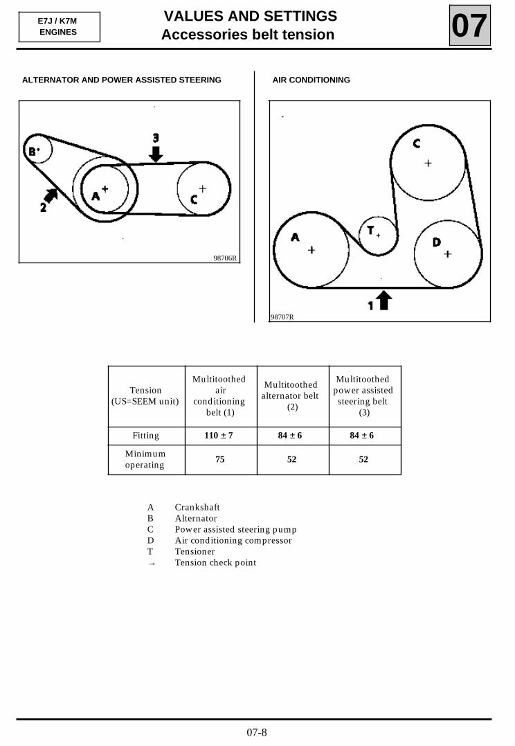
A CrankshaftB AlternatorC Power assisted steering pumpD Air conditioning compressorT Tensioner→ Tension check point
ALTERNATOR AND POWER ASSISTED STEERING
E7J / K7MENGINES
98707R
Tension(US=SEEM unit)
Multitoothedair
conditioningbelt (1)
Multitoothedalternator belt
(2)
Multitoothedpower assistedsteering belt
(3)
Fitting 110 ± 7 84 ± 6 84 ± 6
Minimumoperating 75 52 52
AIR CONDITIONING
07-8
VALUES AND SETTINGSAccessories belt tension 07
98751R
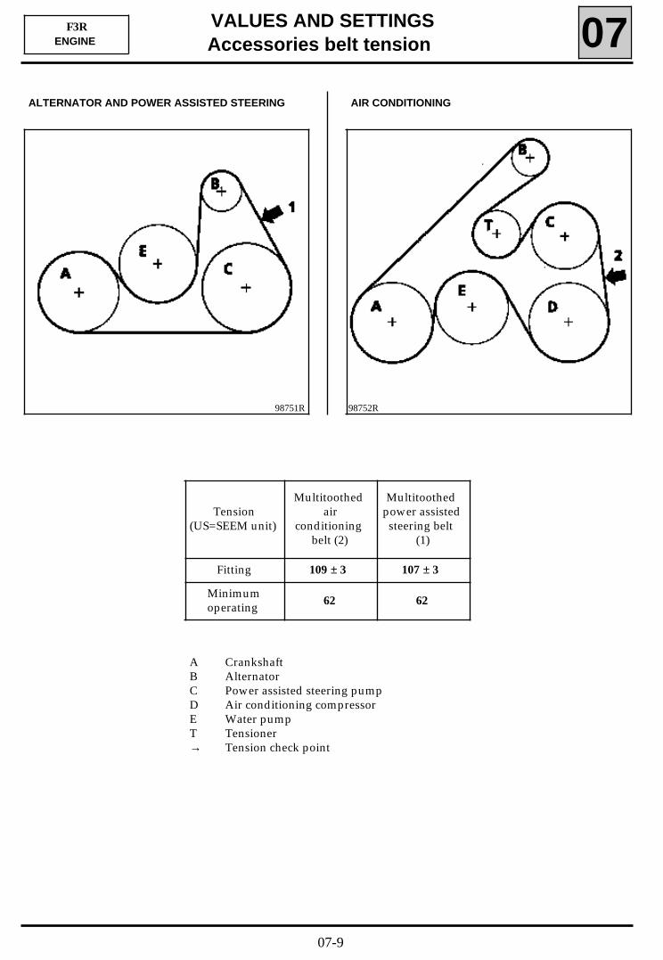
AIR CONDITIONINGALTERNATOR AND POWER ASSISTED STEERING
F3RENGINE
98752R
A CrankshaftB AlternatorC Power assisted steering pumpD Air conditioning compressorE Water pumpT Tensioner→ Tension check point
Tension(US=SEEM unit)
Multitoothedair
conditioningbelt (2)
Multitoothedpower assistedsteering belt
(1)
Fitting 109 ± 3 107 ± 3
Minimumoperating 62 62
07-9
VALUES AND SETTINGSAccessories belt tension 07
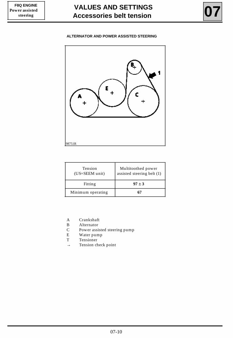
98751R
ALTERNATOR AND POWER ASSISTED STEERING
F8Q ENGINEPower assisted
steering
A CrankshaftB AlternatorC Power assisted steering pumpE Water pumpT Tensioner→ Tension check point
Tension(US=SEEM unit)
Multitoothed powerassisted steering belt (1)
Fitting 97 ± 3
Minimum operating 67
07-10
VALUES AND SETTINGSAccessories belt tension 07
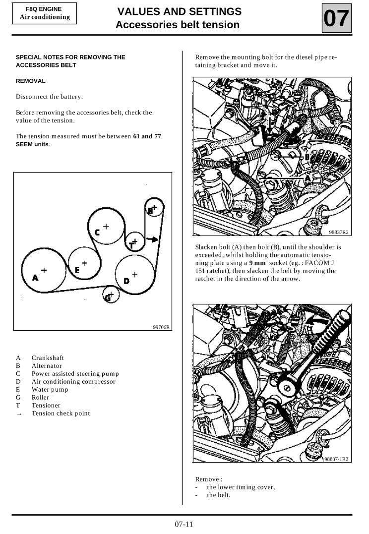
98837-1R2
Remove :- the lower timing cover,- the belt.
SPECIAL NOTES FOR REMOVING THEACCESSORIES BELT
REMOVAL
Disconnect the battery.
Before removing the accessories belt, check thevalue of the tension.
The tension measured must be between 61 and 77SEEM units.
F8Q ENGINEAir conditioning
98837R2
Slacken bolt (A) then bolt (B), until the shoulder isexceeded, whilst holding the automatic tensio-ning plate using a 9 mm socket (eg. : FACOM J151 ratchet), then slacken the belt by moving theratchet in the direction of the arrow.
Remove the mounting bolt for the diesel pipe re-taining bracket and move it.
99706R
A CrankshaftB AlternatorC Power assisted steering pumpD Air conditioning compressorE Water pumpG RollerT Tensioner→ Tension check point
07-11
VALUES AND SETTINGSAccessories belt tension 07
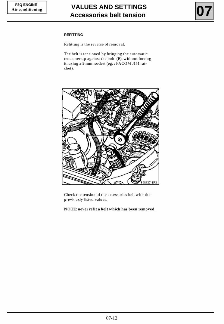
REFITTING
Refitting is the reverse of removal.
The belt is tensioned by bringing the automatictensioner up against the bolt (B), without forcingit, using a 9 mm socket (eg. : FACOM J151 rat-chet).
F8Q ENGINEAir conditioning
98837-1R3
Check the tension of the accessories belt with thepreviously listed values.
NOTE: never refit a belt which has been removed.
07-12
VALUES AND SETTINGSTiming belt tension 07
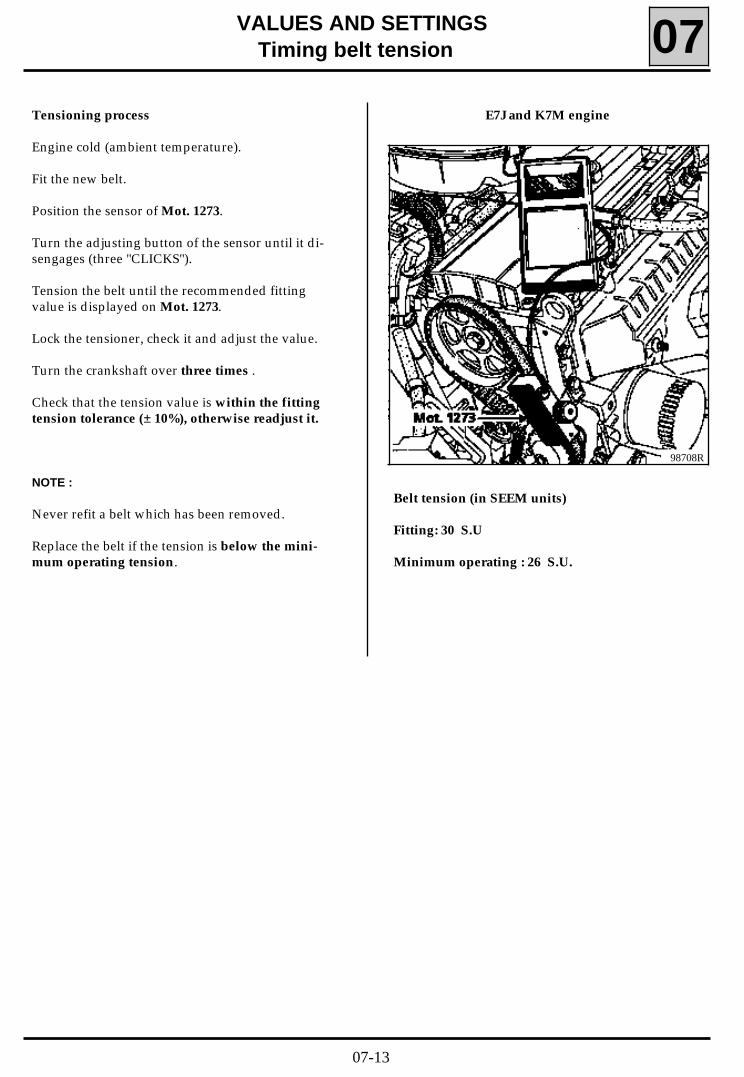
98708R
E7J and K7M engineTensioning process
Engine cold (ambient temperature).
Fit the new belt.
Position the sensor of Mot. 1273.
Turn the adjusting button of the sensor until it di-sengages (three "CLICKS").
Tension the belt until the recommended fittingvalue is displayed on Mot. 1273.
Lock the tensioner, check it and adjust the value.
Turn the crankshaft over three times .
Check that the tension value is within the fittingtension tolerance (± 10%), otherwise readjust it.
NOTE :
Never refit a belt which has been removed.
Replace the belt if the tension is below the mini-mum operating tension.
Belt tension (in SEEM units)
Fitting: 30 S.U
Minimum operating : 26 S.U.
07-13
VALUES AND SETTINGSTiming belt tension 07
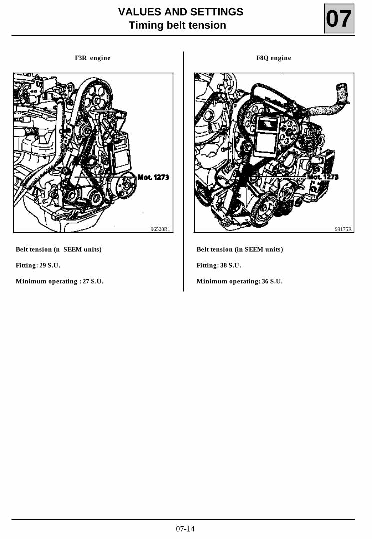
F3R engine
96528R1
Belt tension (n SEEM units)
Fitting: 29 S.U.
Minimum operating : 27 S.U.
F8Q engine
99175R
Belt tension (in SEEM units)
Fitting: 38 S.U.
Minimum operating: 36 S.U.
07-14
VALUES AND SETTINGSTightening the cylinder head 07
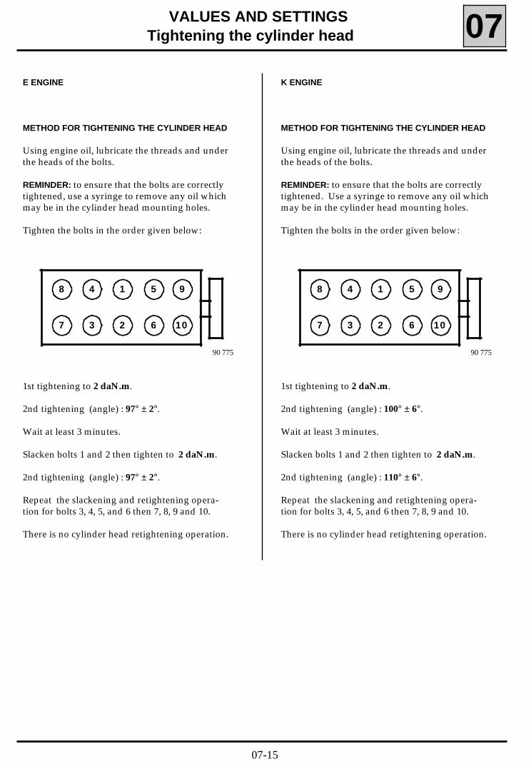
METHOD FOR TIGHTENING THE CYLINDER HEAD
Using engine oil, lubricate the threads and underthe heads of the bolts.
REMINDER: to ensure that the bolts are correctlytightened, use a syringe to remove any oil whichmay be in the cylinder head mounting holes.
Tighten the bolts in the order given below:
90 775
27 6 10
18 5 94
3
1st tightening to 2 daN.m.
2nd tightening (angle) : 97° ± 2°.
Wait at least 3 minutes.
Slacken bolts 1 and 2 then tighten to 2 daN.m.
2nd tightening (angle) : 97° ± 2°.
Repeat the slackening and retightening opera-tion for bolts 3, 4, 5, and 6 then 7, 8, 9 and 10.
There is no cylinder head retightening operation.
E ENGINE
METHOD FOR TIGHTENING THE CYLINDER HEAD
Using engine oil, lubricate the threads and underthe heads of the bolts.
REMINDER: to ensure that the bolts are correctlytightened. Use a syringe to remove any oil whichmay be in the cylinder head mounting holes.
Tighten the bolts in the order given below:
90 775
27 6 10
18 5 94
3
1st tightening to 2 daN.m.
2nd tightening (angle) : 100° ± 6°.
Wait at least 3 minutes.
Slacken bolts 1 and 2 then tighten to 2 daN.m.
2nd tightening (angle) : 110° ± 6°.
Repeat the slackening and retightening opera-tion for bolts 3, 4, 5, and 6 then 7, 8, 9 and 10.
There is no cylinder head retightening operation.
K ENGINE
07-15
VALUES AND SETTINGSTightening the cylinder head 07
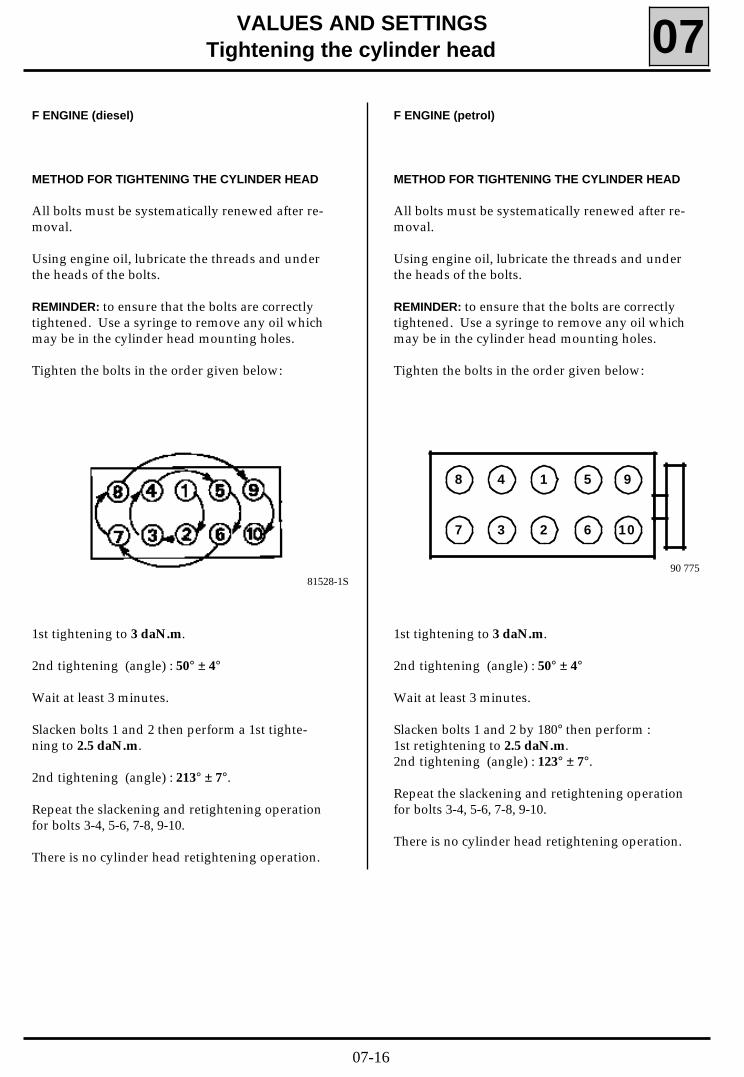
METHOD FOR TIGHTENING THE CYLINDER HEAD
All bolts must be systematically renewed after re-moval.
Using engine oil, lubricate the threads and underthe heads of the bolts.
REMINDER: to ensure that the bolts are correctlytightened. Use a syringe to remove any oil whichmay be in the cylinder head mounting holes.
Tighten the bolts in the order given below:
1st tightening to 3 daN.m.
2nd tightening (angle) : 50° ± 4°
Wait at least 3 minutes.
Slacken bolts 1 and 2 then perform a 1st tighte-ning to 2.5 daN.m.
2nd tightening (angle) : 213° ± 7°.
Repeat the slackening and retightening operationfor bolts 3-4, 5-6, 7-8, 9-10.
There is no cylinder head retightening operation.
F ENGINE (diesel)
METHOD FOR TIGHTENING THE CYLINDER HEAD
All bolts must be systematically renewed after re-moval.
Using engine oil, lubricate the threads and underthe heads of the bolts.
REMINDER: to ensure that the bolts are correctlytightened. Use a syringe to remove any oil whichmay be in the cylinder head mounting holes.
Tighten the bolts in the order given below:
90 775
27 6 10
18 5 94
3
F ENGINE (petrol)
81528-1S
1st tightening to 3 daN.m.
2nd tightening (angle) : 50° ± 4°
Wait at least 3 minutes.
Slacken bolts 1 and 2 by 180° then perform :1st retightening to 2.5 daN.m.2nd tightening (angle) : 123° ± 7°.
Repeat the slackening and retightening operationfor bolts 3-4, 5-6, 7-8, 9-10.
There is no cylinder head retightening operation.
07-16

VALUES AND SETTINGSDimensions of the main braking components 07
FRONT BRAKE (dimensions in mm)
Slave cylinder diameter
Disc diameter
Disc thickness
Minimum disc thickness
Lining thickness (including backing plate)
Minimum lining thickness (including backing plate)
Maximum disc run-out
REAR BRAKE (dimensions in mm)
Slave cylinder diameter
Drum diameter
Maximum drum diameter after regrinding
MASTER CYLINDER (dimensions in mm)
Diameter
48
238
12
10.3
18
7
0.07
17.5
203.2
204.4
20.6
BA0G
48
259
20.60
19
18
6
0.07
17.5
203.2
204.4
20.6
48
238
20
18.3
18
6.5
0.07
17.5
203.2
204.4
20.6
Brakes discs cannot be repaired. They must be replaced if large scratches or excessive wear occur.
BA0F
BA0ABA0EBA0LBA0U
07-17
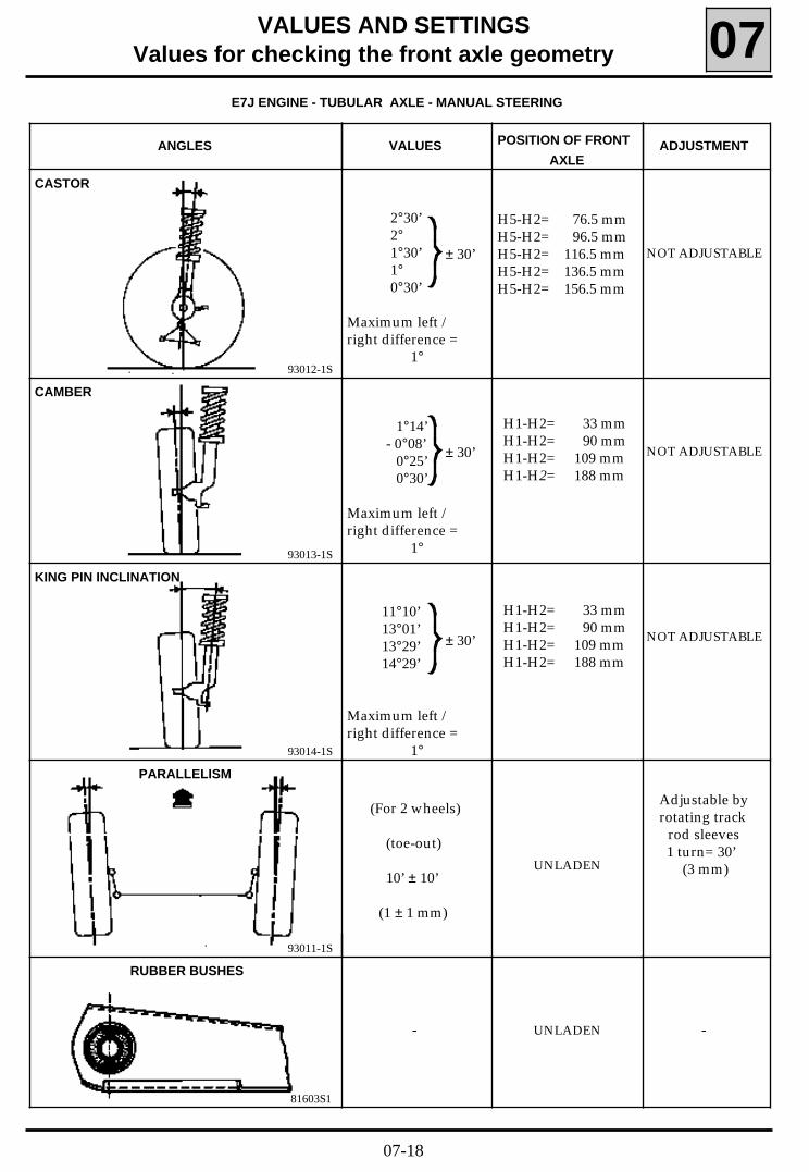
H5-H2= 76.5 mmH5-H2= 96.5 mmH5-H2= 116.5 mmH5-H2= 136.5 mmH5-H2= 156.5 mm
81603S1
93011-1S
93014-1S
93013-1S
93012-1S
VALUES AND SETTINGSValues for checking the front axle geometry 07
UNLADEN
NOT ADJUSTABLE
NOT ADJUSTABLE
NOT ADJUSTABLE
CAMBER
VALUES
CASTOR
2°30’2°1°30’1°0°30’
Maximum left /right difference =
1°
1°14’- 0°08’
0°25’0°30’
Maximum left /right difference =
1°
ADJUSTMENTPOSITION OF FRONT
AXLE
KING PIN INCLINATION
11°10’13°01’13°29’14°29’
Maximum left /right difference =
1°
H1-H2= 33 mmH1-H2= 90 mmH1-H2= 109 mmH1-H2= 188 mm
H1-H2= 33 mmH1-H2= 90 mmH1-H2= 109 mmH1-H2= 188 mm
PARALLELISM
RUBBER BUSHES
Adjustable byrotating track
rod sleeves 1 turn= 30’
(3 mm)
(For 2 wheels)
(toe-out)
10’ ± 10’
(1 ± 1 mm)
ANGLES
UNLADEN- -
± 30’
± 30’
± 30’
E7J ENGINE - TUBULAR AXLE - MANUAL STEERING
07-18
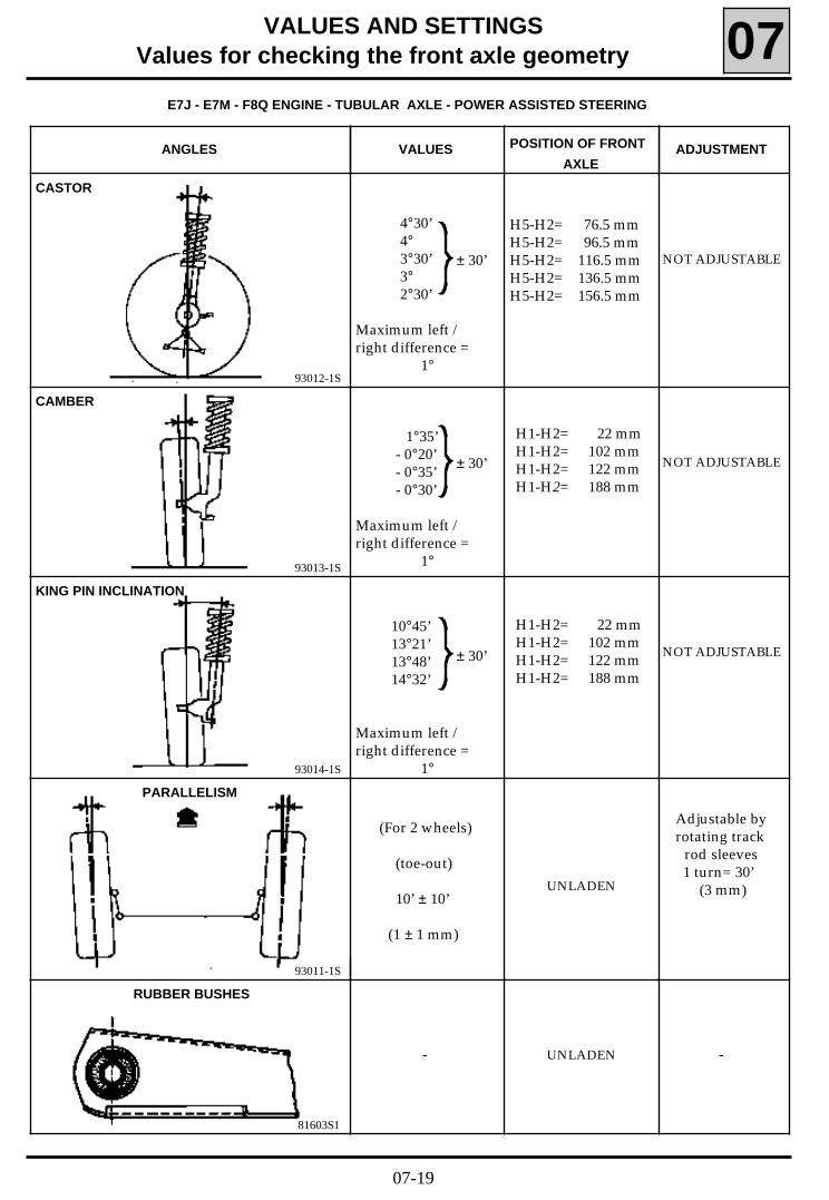
H5-H2= 76.5 mmH5-H2= 96.5 mmH5-H2= 116.5 mmH5-H2= 136.5 mmH5-H2= 156.5 mm
81603S1
93011-1S
93014-1S
93013-1S
93012-1S
VALUES AND SETTINGSValues for checking the front axle geometry 07
UNLADEN
NOT ADJUSTABLE
NOT ADJUSTABLE
NOT ADJUSTABLE
CAMBER
VALUES
CASTOR
4°30’4°3°30’3°2°30’
Maximum left /right difference =
1°
1°35’- 0°20’- 0°35’- 0°30’
Maximum left /right difference =
1°
ADJUSTMENTPOSITION OF FRONT
AXLE
KING PIN INCLINATION
10°45’13°21’13°48’14°32’
Maximum left /right difference =
1°
H1-H2= 22 mmH1-H2= 102 mmH1-H2= 122 mmH1-H2= 188 mm
H1-H2= 22 mmH1-H2= 102 mmH1-H2= 122 mmH1-H2= 188 mm
PARALLELISM
RUBBER BUSHES
Adjustable byrotating track
rod sleeves 1 turn= 30’
(3 mm)
(For 2 wheels)
(toe-out)
10’ ± 10’
(1 ± 1 mm)
ANGLES
UNLADEN- -
± 30’
± 30’
± 30’
E7J - E7M - F8Q ENGINE - TUBULAR AXLE - POWER ASSISTED STEERING
07-19

H5-H2= 71,5 mmH5-H2= 91,5 mmH5-H2= 111,5 mmH5-H2= 131,5 mmH5-H2= 151,5 mm
81603S1
93011-1S
93014-1S
93013-1S
93012-1S
VALUES AND SETTINGSValues for checking the front axle geometry 07
UNLADEN
NOT ADJUSTABLE
NOT ADJUSTABLE
NOT ADJUSTABLE
CAMBER
VALUES
CASTOR
4°30’4°3°30’3°2°30’
Maximum left /right difference =
1°
1°35’- 0°20’- 0°37’- 0°30’
Maximum left /right difference =
1°
ADJUSTMENTPOSITION OF FRONT
AXLE
KING PIN INCLINATION
10°45’13°20’13°53’14°32’
Maximum left /right difference =
1°
H1-H2= 22 mmH1-H2= 102 mmH1-H2= 122 mmH1-H2= 188 mm
H1-H2= 22 mmH1-H2= 102 mmH1-H2= 122 mmH1-H2= 188 mm
PARALLELISM
RUBBER BUSHES
Adjustable byrotating track
rod sleeves 1 turn= 30’
(3 mm)
(For 2 wheels)
(toe-out)
10’ ± 10’
(1 ± 1 mm)
ANGLES
UNLADEN- -
± 30’
± 30’
± 30’
F3R ENGINE - 4 BAR AXLE - POWER ASSISTED STEERING
07-20

- 30’ ± 20’
(Toe-in)
or
- 3 ± 2mm
- 0°50’ ± 15’
NOT ADJUSTABLE
93013-2S
93011-2S
81603S1
VALUES AND SETTINGSValues for checking the rear axle geometry 07
UNLADEN
CAMBER
VALUES ADJUSTMENTPOSITION OF REAR
AXLE
PARALLELISM
ANGLES
UNLADEN- 1° ± 15’ NOT ADJUSTABLE
- 50’ ± 20’
(Toe- in)
or
- 5 ± 2mm
UNLADEN- -
RUBBER BUSHES
TUBULAR AND 4BAR REAR AXLE
TUBULAR AND 4BAR REAR AXLE
REAR AXLE
TUBULAR 4 BAR
07-21
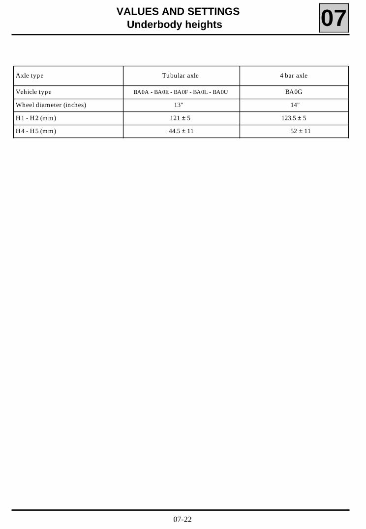
VALUES AND SETTINGSUnderbody heights 07
Axle type Tubular axle 4 bar axle
Vehicle type BA0A - BA0E - BA0F - BA0L - BA0U BA0G
Wheel diameter (inches) 13" 14"
H1 - H2 (mm) 121 ± 5 123.5 ± 5
H4 - H5 (mm) 44.5 ± 11 52 ± 11
07-22

VALUES AND SETTINGSBrake limiter 07
These vehicles are fitted with limiters which are load sensitive.
They are checked and adjusted when :- the vehicle is unladen,- the fuel tank is full,- the driver is in the vehicle.
Vehicle type
Fuel tank
Front Rear
Control pressure (Bar)
BA0G100 72
BA0ABA0EBA0FBA0LBA0U
100Full
90966S
+0-8
62 +0-8
07-23