removing water contamination from ammonia systems grasso ... documents/grasso ammonia … · grasso...
TRANSCRIPT
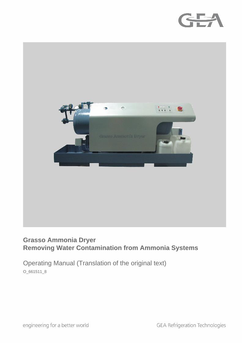
Grasso Ammonia DryerRemoving Water Contamination from Ammonia Systems
Operating Manual (Translation of the original text)O_661511_8
COPYRIGHTAll Rights reserved.No part of this publication may be copied or pub-lished by means of printing, photocopying, microfilmor otherwise without prior written consent of
• GEA Refrigeration Germany GmbHherein after called manufacturer. This restrictionalso applies to the corresponding drawings and dia-grams.
LEGAL NOTICEThis documentation has been written in all con-science. However, the manufacturer cannot be heldresponsible, neither for any errors occurring in thisdocumentation nor for their consequences.
Operating Manual | Removing Water Contamination from Ammonia SystemsGrasso Ammonia Dryer
2 GEA Refrigeration Germany GmbH | O_661511_8 | Generated 04.08.2014
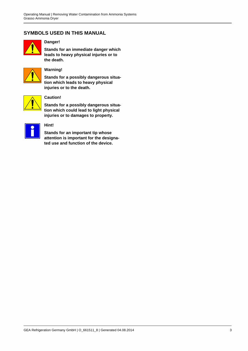
SYMBOLS USED IN THIS MANUALDanger!
Stands for an immediate danger whichleads to heavy physical injuries or tothe death.
Warning!
Stands for a possibly dangerous situa-tion which leads to heavy physicalinjuries or to the death.
Caution!
Stands for a possibly dangerous situa-tion which could lead to light physicalinjuries or to damages to property.
Hint!
Stands for an important tip whoseattention is important for the designa-ted use and function of the device.
Operating Manual | Removing Water Contamination from Ammonia SystemsGrasso Ammonia Dryer
GEA Refrigeration Germany GmbH | O_661511_8 | Generated 04.08.2014 3
Operating Manual | Removing Water Contamination from Ammonia SystemsGrasso Ammonia Dryer
4 GEA Refrigeration Germany GmbH | O_661511_8 | Generated 04.08.2014
TABLE OF CONTENTS1 TRANSPORT INSTRUCTIONS 7
1.1 Transport and storage 72 DESCRIPTION OF DESIGN AND FUNCTION 8
2.1 Grasso Ammonia Dryer GAD 150H with hotgas heating 82.1.1 Technical data 82.1.2 Function 82.1.3 Design 92.1.4 Customer parts list 11
2.2 Grasso Ammonia Dryer GAD 150E with electric heating element 132.2.1 Technical data 132.2.2 Function 132.2.3 Design 142.2.4 Customer parts list 16
3 OPERATING INSTRUCTIONS 183.1 Commissioning 183.2 Draining 193.3 Environment protection 203.4 Fault message 203.5 Switching off 203.6 Key assignment 21
4 MAINTENANCE INSTRUCTION 224.1 Maintenance work 224.2 Cleaning the vessel 22
5 ALARMS 245.1 Fault indications 24
6 TEST PROCEDURE 256.1 Procedure to determine the water content in ammonia refrigerating cycles (measurement) 256.2 Calculation of water concentration 266.3 Result of measuremen 27
Operating Manual | Removing Water Contamination from Ammonia SystemsGrasso Ammonia Dryer
GEA Refrigeration Germany GmbH | O_661511_8 | Generated 04.08.2014 5

Operating Manual | Removing Water Contamination from Ammonia SystemsGrasso Ammonia Dryer
6 GEA Refrigeration Germany GmbH | O_661511_8 | Generated 04.08.2014
1 TRANSPORT INSTRUCTIONS
1.1 Transport and storage
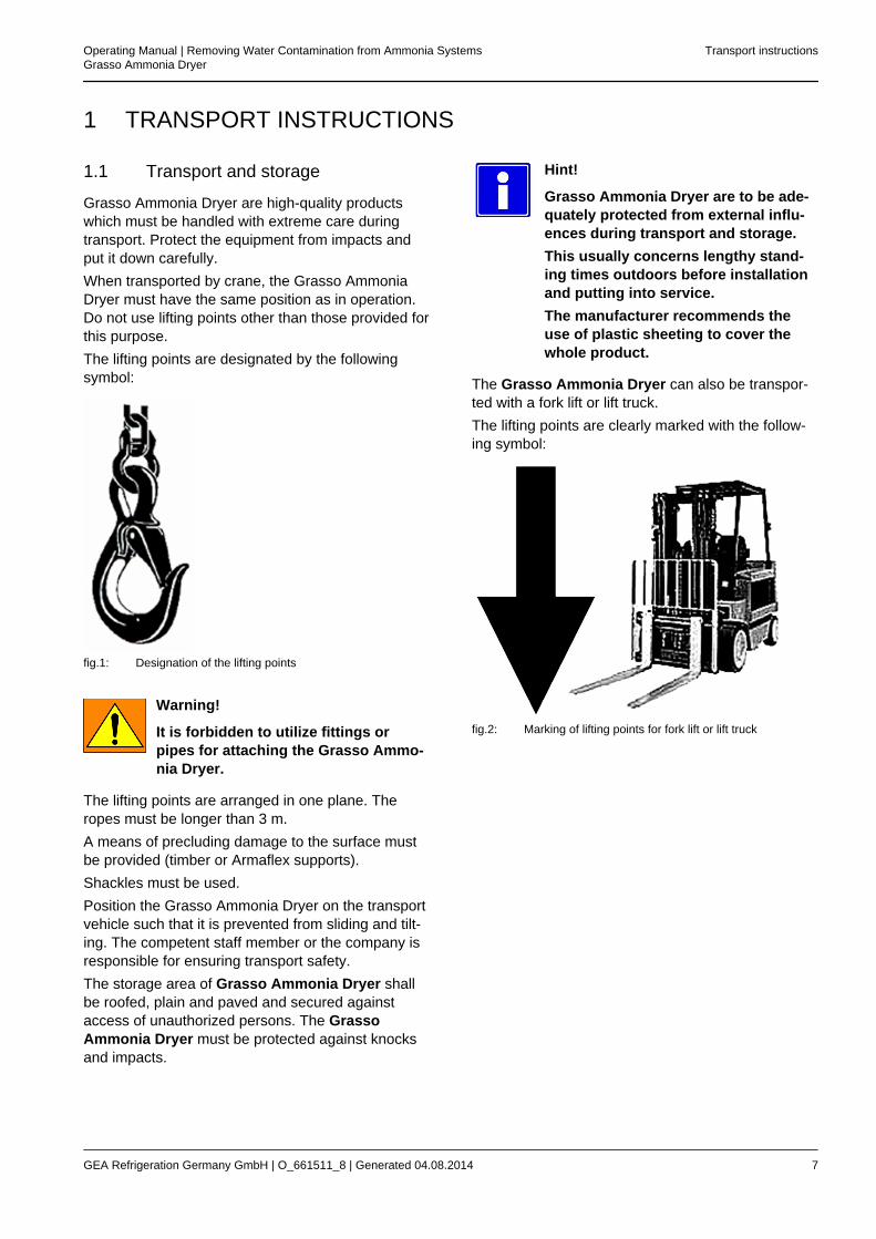
Grasso Ammonia Dryer are high-quality productswhich must be handled with extreme care duringtransport. Protect the equipment from impacts andput it down carefully.When transported by crane, the Grasso AmmoniaDryer must have the same position as in operation.Do not use lifting points other than those provided forthis purpose.The lifting points are designated by the followingsymbol:
fig.1: Designation of the lifting points
Warning!
It is forbidden to utilize fittings orpipes for attaching the Grasso Ammo-nia Dryer.
The lifting points are arranged in one plane. Theropes must be longer than 3 m.A means of precluding damage to the surface mustbe provided (timber or Armaflex supports).Shackles must be used.Position the Grasso Ammonia Dryer on the transportvehicle such that it is prevented from sliding and tilt-ing. The competent staff member or the company isresponsible for ensuring transport safety.The storage area of Grasso Ammonia Dryer shallbe roofed, plain and paved and secured againstaccess of unauthorized persons. The GrassoAmmonia Dryer must be protected against knocksand impacts.
Hint!
Grasso Ammonia Dryer are to be ade-quately protected from external influ-ences during transport and storage.This usually concerns lengthy stand-ing times outdoors before installationand putting into service.The manufacturer recommends theuse of plastic sheeting to cover thewhole product.
The Grasso Ammonia Dryer can also be transpor-ted with a fork lift or lift truck.The lifting points are clearly marked with the follow-ing symbol:
fig.2: Marking of lifting points for fork lift or lift truck
Operating Manual | Removing Water Contamination from Ammonia SystemsGrasso Ammonia Dryer
Transport instructions
GEA Refrigeration Germany GmbH | O_661511_8 | Generated 04.08.2014 7
2 DESCRIPTION OF DESIGN AND FUNCTION
2.1 Grasso Ammonia Dryer GAD 150Hwith hotgas heating
2.1.1 Technical data
The type designation is mentioned on the machineplate.The device is applicable for ammonia only.
Refrigerant charge 110 kg
max. operating pressure 23.0 bar g.p.
Operating limits
Min. evaporating tem-perature of plant to bedehumidfyied
- 43°C
Max. evaporating tem-perature of plant to bedehumidfyied
5 °C
Dimensions, Weight
Length 2,200 mm
Width 750 mm
Height 1000 mm
Weight, empty 480 kg
Power supply
Voltage 400 V, 3~, 50 Hz
Rating 0.2 kW
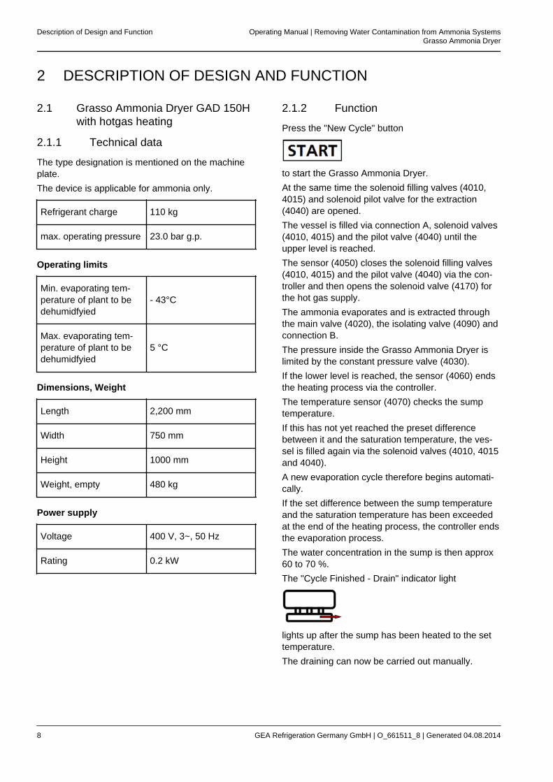
2.1.2 Function
Press the "New Cycle" button
to start the Grasso Ammonia Dryer.At the same time the solenoid filling valves (4010,4015) and solenoid pilot valve for the extraction(4040) are opened.The vessel is filled via connection A, solenoid valves(4010, 4015) and the pilot valve (4040) until theupper level is reached.The sensor (4050) closes the solenoid filling valves(4010, 4015) and the pilot valve (4040) via the con-troller and then opens the solenoid valve (4170) forthe hot gas supply.The ammonia evaporates and is extracted throughthe main valve (4020), the isolating valve (4090) andconnection B.The pressure inside the Grasso Ammonia Dryer islimited by the constant pressure valve (4030).If the lower level is reached, the sensor (4060) endsthe heating process via the controller.The temperature sensor (4070) checks the sumptemperature.If this has not yet reached the preset differencebetween it and the saturation temperature, the ves-sel is filled again via the solenoid valves (4010, 4015and 4040).A new evaporation cycle therefore begins automati-cally.If the set difference between the sump temperatureand the saturation temperature has been exceededat the end of the heating process, the controller endsthe evaporation process.The water concentration in the sump is then approx60 to 70 %.The "Cycle Finished - Drain" indicator light
lights up after the sump has been heated to the settemperature.The draining can now be carried out manually.
Description of Design and Function Operating Manual | Removing Water Contamination from Ammonia SystemsGrasso Ammonia Dryer
8 GEA Refrigeration Germany GmbH | O_661511_8 | Generated 04.08.2014
Warning!
Note and follow the safety instruc-tions!
2.1.3 Design
The layout of the Grasso Ammonia Dryer GAD 150 H is shown in the diagram below and consists of the follow-ing components:
Item No. Designation
4010 1 Solenoid valve, MV 1.1
4015 1 Solenoid valve, MV 1.2
4020 1 Main valve
4030 1 Pilot valve CVP
4040 1 Pilot valve EVM, MV 2
4050, 4060 1 Level sensor
4070 1 Temperature sensor
4080 1 Overflow valve DN 15, 23 bar
4090 1 Stop valve
4100 1 Isolating valve with quick closing valve
4110 1 Stop valve
4130 1 Service valve, Pump down
4140 1 Pressure gauge, -1 / 25 bar
4145 1 Pressure gauge stop valve
4160 1 Vent valve
4170 1 Solenoid valve, hot gas
4180 1 Manual control valve
4190 1 Automatic steam trap
4210, 4211 1 Evaporation vessel
Operating Manual | Removing Water Contamination from Ammonia SystemsGrasso Ammonia Dryer
Description of Design and Function
GEA Refrigeration Germany GmbH | O_661511_8 | Generated 04.08.2014 9
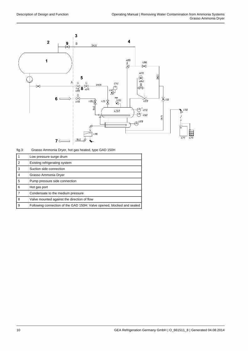
fig.3: Grasso Ammonia Dryer, hot gas heated, type GAD 150H
1 Low pressure surge drum
2 Existing refrigerating system
3 Suction side connection
4 Grasso Ammonia Dryer
5 Pump pressure side connection
6 Hot gas port
7 Condensate to the medium pressure
8 Valve mounted against the direction of flow
9 Following connection of the GAD 150H: Valve opened, blocked and sealed
Description of Design and Function Operating Manual | Removing Water Contamination from Ammonia SystemsGrasso Ammonia Dryer
10 GEA Refrigeration Germany GmbH | O_661511_8 | Generated 04.08.2014
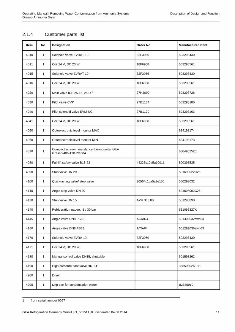
2.1.4 Customer parts list
Item No. Designation Order No: Manufacturer Ident
4010 1 Solenoid valve EVRAT 10 32F3056 503298430
4011 1 Coil 24 V, DC 20 W 18F6968 503298561
4015 1 Solenoid valve EVRAT 10 32F3056 503298430
4016 1 Coil 24 V, DC 20 W 18F6968 503298561
4020 1 Main valve ICS 25-15, 25 D 1 27H2090 503298728
4030 1 Pilot valve CVP 27B1164 503298180
4040 1 Pilot solenoid valve EVM-NC 27B1120 503298163
4041 1 Coil 24 V, DC 20 W 18F6968 503298561
4050 1 Optoelectronic level monitor MAX 634198174
4060 1 Optoelectronic level monitor MIN 634198173
4070 1 Compact screw-in resistance thermometer GEAGrasso-406-120 Pt100A 630498252E
4080 1 Full-lift safety valve B15-23 44223c10a5a10011 500398535
4090 1 Stop valve DN 20 501698022C25
4100 1 Quick-acting valve/ stop valve 96564c1ca5a2e156 500298032
4110 1 Angle stop valve DN 20 501698002C25
4130 1 Stop valve DN 15 AVR 363 00 501298890
4140 1 Refrigeration gauge, -1 / 30 bar 631098327K
4145 1 Angle valve DN8 PS63 AG/AN4 501306632awp63
4160 1 Angle valve DN8 PS63 AC/A84 501299036awp63
4170 1 Solenoid valve EVRA 10 32F3069 503298430
4171 1 Coil 24 V, DC 20 W 18F6968 503298561
4180 1 Manual control valve DN15, shuttable 501598262
4190 1 High pressure float valve HR 1-H 355598026F3S
4200 1 Dryer
4205 1 Drip pan for condensation water B2385910
1 from serial number 0097
Operating Manual | Removing Water Contamination from Ammonia SystemsGrasso Ammonia Dryer
Description of Design and Function
GEA Refrigeration Germany GmbH | O_661511_8 | Generated 04.08.2014 11
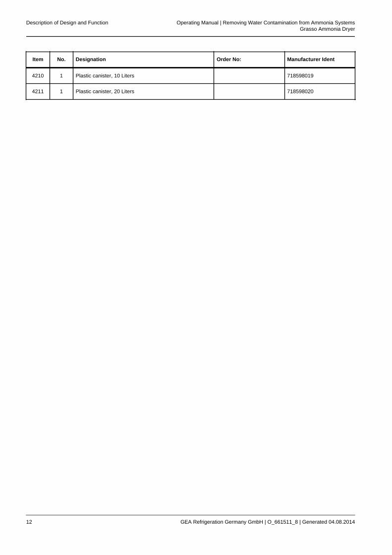
Item No. Designation Order No: Manufacturer Ident
4210 1 Plastic canister, 10 Liters 718598019
4211 1 Plastic canister, 20 Liters 718598020
Description of Design and Function Operating Manual | Removing Water Contamination from Ammonia SystemsGrasso Ammonia Dryer
12 GEA Refrigeration Germany GmbH | O_661511_8 | Generated 04.08.2014
2.2 Grasso Ammonia Dryer GAD 150Ewith electric heating element
2.2.1 Technical data
The type designation is mentioned on the machineplate.The device is applicable for ammonia only.
Refrigerant charge 110 kg
max. operating pressure 23.0 bar g.p.
Operating limits
Min. evaporating tem-perature of plant to bedehumidfyied
- 43°C
Max. evaporating tem-perature of plant to bedehumidfyied
5 °C
Dimensions, Weight
Length 2,200 mm
Width 750 mm
Height 1000 mm
Weight, empty 500 kg
Power supply
Voltage 400 V, 3~, 50 Hz
Rating 1.8 kW
2.2.2 Function
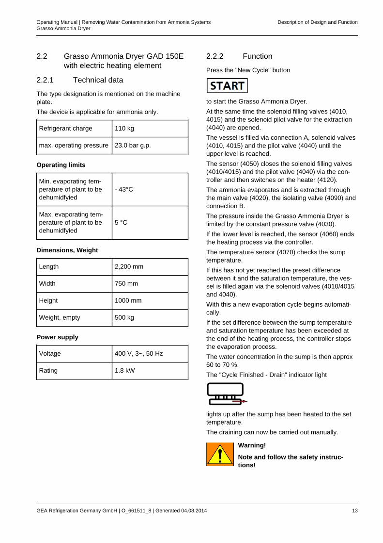
Press the "New Cycle" button
to start the Grasso Ammonia Dryer.At the same time the solenoid filling valves (4010,4015) and the solenoid pilot valve for the extraction(4040) are opened.The vessel is filled via connection A, solenoid valves(4010, 4015) and the pilot valve (4040) until theupper level is reached.The sensor (4050) closes the solenoid filling valves(4010/4015) and the pilot valve (4040) via the con-troller and then switches on the heater (4120).The ammonia evaporates and is extracted throughthe main valve (4020), the isolating valve (4090) andconnection B.The pressure inside the Grasso Ammonia Dryer islimited by the constant pressure valve (4030).If the lower level is reached, the sensor (4060) endsthe heating process via the controller.The temperature sensor (4070) checks the sumptemperature.If this has not yet reached the preset differencebetween it and the saturation temperature, the ves-sel is filled again via the solenoid valves (4010/4015and 4040).With this a new evaporation cycle begins automati-cally.If the set difference between the sump temperatureand saturation temperature has been exceeded atthe end of the heating process, the controller stopsthe evaporation process.The water concentration in the sump is then approx60 to 70 %.The "Cycle Finished - Drain" indicator light
lights up after the sump has been heated to the settemperature.The draining can now be carried out manually.
Warning!
Note and follow the safety instruc-tions!
Operating Manual | Removing Water Contamination from Ammonia SystemsGrasso Ammonia Dryer
Description of Design and Function
GEA Refrigeration Germany GmbH | O_661511_8 | Generated 04.08.2014 13
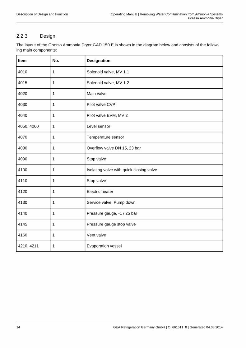
2.2.3 Design
The layout of the Grasso Ammonia Dryer GAD 150 E is shown in the diagram below and consists of the follow-ing main components:
Item No. Designation
4010 1 Solenoid valve, MV 1.1
4015 1 Solenoid valve, MV 1.2
4020 1 Main valve
4030 1 Pilot valve CVP
4040 1 Pilot valve EVM, MV 2
4050, 4060 1 Level sensor
4070 1 Temperature sensor
4080 1 Overflow valve DN 15, 23 bar
4090 1 Stop valve
4100 1 Isolating valve with quick closing valve
4110 1 Stop valve
4120 1 Electric heater
4130 1 Service valve, Pump down
4140 1 Pressure gauge, -1 / 25 bar
4145 1 Pressure gauge stop valve
4160 1 Vent valve
4210, 4211 1 Evaporation vessel
Description of Design and Function Operating Manual | Removing Water Contamination from Ammonia SystemsGrasso Ammonia Dryer
14 GEA Refrigeration Germany GmbH | O_661511_8 | Generated 04.08.2014
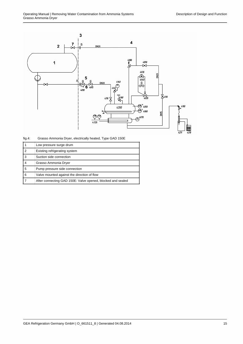
fig.4: Grasso Ammonia Dryer, electrically heated, Type GAD 150E
1 Low pressure surge drum
2 Existing refrigerating system
3 Suction side connection
4 Grasso Ammonia Dryer
5 Pump pressure side connection
6 Valve mounted against the direction of flow
7 After connecting GAD 150E: Valve opened, blocked and sealed
Operating Manual | Removing Water Contamination from Ammonia SystemsGrasso Ammonia Dryer
Description of Design and Function
GEA Refrigeration Germany GmbH | O_661511_8 | Generated 04.08.2014 15
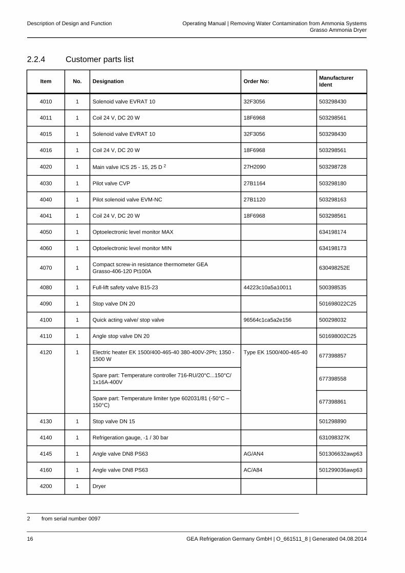
2.2.4 Customer parts list
Item No. Designation Order No: ManufacturerIdent
4010 1 Solenoid valve EVRAT 10 32F3056 503298430
4011 1 Coil 24 V, DC 20 W 18F6968 503298561
4015 1 Solenoid valve EVRAT 10 32F3056 503298430
4016 1 Coil 24 V, DC 20 W 18F6968 503298561
4020 1 Main valve ICS 25 - 15, 25 D 2 27H2090 503298728
4030 1 Pilot valve CVP 27B1164 503298180
4040 1 Pilot solenoid valve EVM-NC 27B1120 503298163
4041 1 Coil 24 V, DC 20 W 18F6968 503298561
4050 1 Optoelectronic level monitor MAX 634198174
4060 1 Optoelectronic level monitor MIN 634198173
4070 1 Compact screw-in resistance thermometer GEAGrasso-406-120 Pt100A 630498252E
4080 1 Full-lift safety valve B15-23 44223c10a5a10011 500398535
4090 1 Stop valve DN 20 501698022C25
4100 1 Quick acting valve/ stop valve 96564c1ca5a2e156 500298032
4110 1 Angle stop valve DN 20 501698002C25
4120 1 Electric heater EK 1500/400-465-40 380-400V-2Ph; 1350 -1500 W
Type EK 1500/400-465-40 677398857
Spare part: Temperature controller 716-RU/20°C...150°C/1x16A-400V 677398558
Spare part: Temperature limiter type 602031/81 (-50°C –150°C) 677398861
4130 1 Stop valve DN 15 501298890
4140 1 Refrigeration gauge, -1 / 30 bar 631098327K
4145 1 Angle valve DN8 PS63 AG/AN4 501306632awp63
4160 1 Angle valve DN8 PS63 AC/A84 501299036awp63
4200 1 Dryer
2 from serial number 0097
Description of Design and Function Operating Manual | Removing Water Contamination from Ammonia SystemsGrasso Ammonia Dryer
16 GEA Refrigeration Germany GmbH | O_661511_8 | Generated 04.08.2014
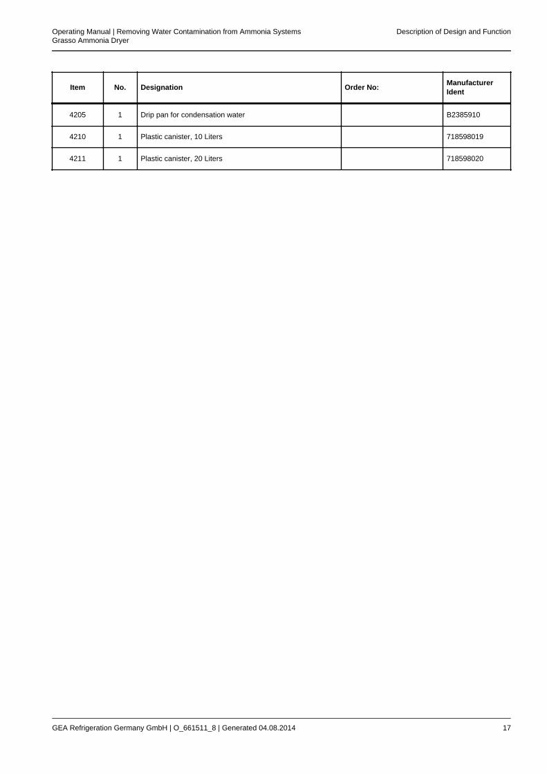
Item No. Designation Order No: ManufacturerIdent
4205 1 Drip pan for condensation water B2385910
4210 1 Plastic canister, 10 Liters 718598019
4211 1 Plastic canister, 20 Liters 718598020
Operating Manual | Removing Water Contamination from Ammonia SystemsGrasso Ammonia Dryer
Description of Design and Function
GEA Refrigeration Germany GmbH | O_661511_8 | Generated 04.08.2014 17
3 OPERATING INSTRUCTIONS
3.1 Commissioning
1. Connection A- connect to the discharge side ofthe low-pressure surge drum (see functionaldescription).
2. Connection B - connect to the suction (intake)side of the low-pressure surge drum (see func-tional description).
Hint!
The connections must be made care-fully and checked for leaks!
3. Evacuate the dryer (GAD).Valve position during evacuation: Valves(4090), (4110), (4130) openValve position during operation: Valves(4090), (4110) open
4. Connect the equipment plug (400 V, 3~ , 50 Hz)
5. Switch the main switch
switch to "I". The GAD is ready for operation.
6. Switching points for temperature sensor (4070)at the controller's display (inside the connectionbox) are permanently preset:
– Evaporating temperature 7 °C
– Temperature for ending the evaporationprocess, sump temperature 15 °C
– End of reheating, sump temperature 35°C
– Fault, sump temperature 45 °C
7. Open the plant valve upstream of connection A.
8. Open the plant valve at connection B.
Hint!
During operation of the GAD, the valveplant valve at connection B must beopened, blocked and sealed to ensurethat on activation of the pressure reliefdevice (4080) the gauge pressureinside the vessel can be discharged tothe suction side of the refrigerationplant.This valve must not be closed againuntil the GAD is to be disconnected.To shut down the GAD during normaloperation, close the plant valveupstream of connection A and initiatea new cycle by pressing the "START"button.After 24 hours the GAD can beswitched off at the main switch.Then close valve 4090.
Operating instructions Operating Manual | Removing Water Contamination from Ammonia SystemsGrasso Ammonia Dryer
18 GEA Refrigeration Germany GmbH | O_661511_8 | Generated 04.08.2014
9. Press the "New Cycle" button:
9.1 The solenoid filling valve MV 1 (4010/4015)and the extraction pilot valve MV 2 (4040)are opened.
9.2 The vessel is now filled until the upperlevel is reached.
9.3 The sensor (4050) closes the solenoidvalves MV 1 (4010/4015) and MV 2 (4040)via the controller and then opens the hotgas solenoid valve (4170) or starts up theheater (4120).
9.4 The ammonia evaporates and is extractedthrough the main valve (4020) by the low-pressure surge drum.
9.5 The pressure inside the Grasso AmmoniaDryer is adjusted to 4.5 bar gauge pres-sure (corresponds to 7°C) by the constantpressure valve (4030) and is checkedusing the pressure gauge (4140).In the event of differences, the constantpressure valve must be adjusted manuallyduring the initial heating process.
9.6 If the lower level is reached, the sensor(4060) ends the heating process via thecontroller.
9.7 If the sump temperature has not yetreached the set value, the vessel is filledagain via solenoid valves MV 1(4010/4015) and MV 2 (4040).
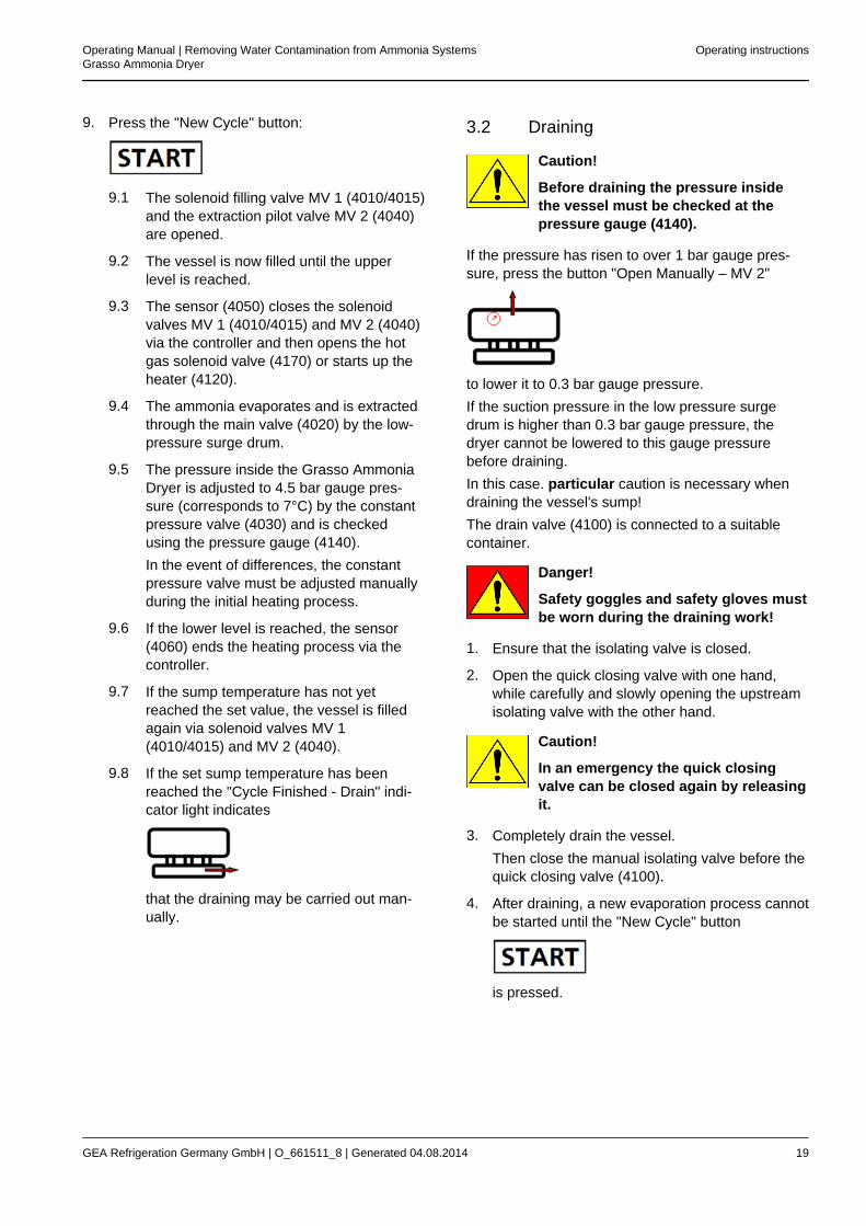
9.8 If the set sump temperature has beenreached the "Cycle Finished - Drain" indi-cator light indicates
that the draining may be carried out man-ually.
3.2 Draining
Caution!
Before draining the pressure insidethe vessel must be checked at thepressure gauge (4140).
If the pressure has risen to over 1 bar gauge pres-sure, press the button "Open Manually – MV 2"
to lower it to 0.3 bar gauge pressure.If the suction pressure in the low pressure surgedrum is higher than 0.3 bar gauge pressure, thedryer cannot be lowered to this gauge pressurebefore draining.In this case. particular caution is necessary whendraining the vessel's sump!The drain valve (4100) is connected to a suitablecontainer.
Danger!
Safety goggles and safety gloves mustbe worn during the draining work!
1. Ensure that the isolating valve is closed.
2. Open the quick closing valve with one hand,while carefully and slowly opening the upstreamisolating valve with the other hand.
Caution!
In an emergency the quick closingvalve can be closed again by releasingit.
3. Completely drain the vessel.Then close the manual isolating valve before thequick closing valve (4100).
4. After draining, a new evaporation process cannotbe started until the "New Cycle" button
is pressed.
Operating Manual | Removing Water Contamination from Ammonia SystemsGrasso Ammonia Dryer
Operating instructions
GEA Refrigeration Germany GmbH | O_661511_8 | Generated 04.08.2014 19
3.3 Environment protection
Danger!
The drained mixture of water andammonia may also contain oil. It must,therefore, be disposed of in accord-ance with local regulations! It must notbe drained into the open air or publicwaters.The operator is responsible for itsproper disposal!
The operator of the refrigeration application isaccountable for unloading and returning the refriger-ant to the specialised trade and for the environmen-tally friendly disposal of the refrigerant and pollutedmaterials.Therefore suitable and specially marked cans mustbe supplied.
3.4 Fault message
If the sump temperature exceeds the limit value, thehot gas solenoid valve (4170) is closed or the heater(4120) is switched off.The vessel must be drained in compliance with theaforementioned safety precautions.After the cause of the fault has been corrected, theevaporation process can be continued by pressingthe "New cycle" button.
A new cycle begins.
3.5 Switching off
Switch the main switch
to "O".
Operating instructions Operating Manual | Removing Water Contamination from Ammonia SystemsGrasso Ammonia Dryer
20 GEA Refrigeration Germany GmbH | O_661511_8 | Generated 04.08.2014
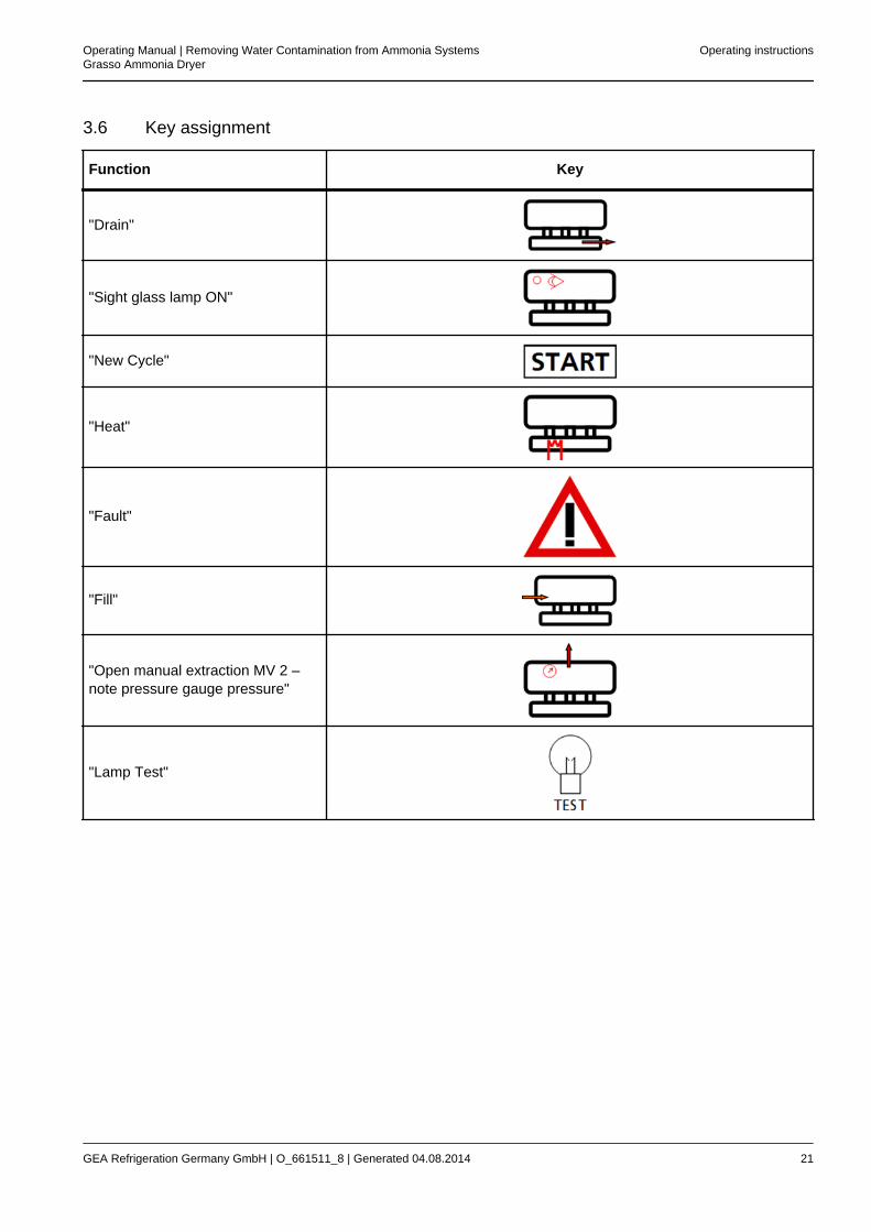
3.6 Key assignment
Function Key
"Drain"
"Sight glass lamp ON"
"New Cycle"
"Heat"
"Fault"
"Fill"
"Open manual extraction MV 2 –note pressure gauge pressure"
"Lamp Test"
Operating Manual | Removing Water Contamination from Ammonia SystemsGrasso Ammonia Dryer
Operating instructions
GEA Refrigeration Germany GmbH | O_661511_8 | Generated 04.08.2014 21
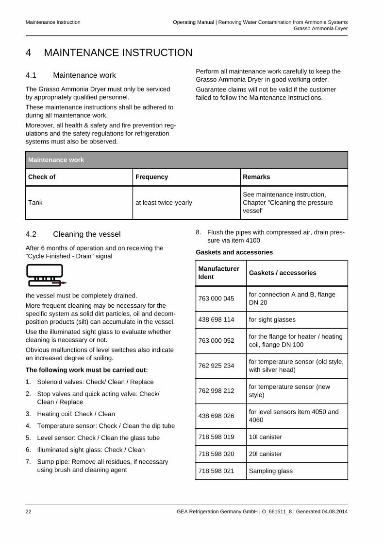
4 MAINTENANCE INSTRUCTION
4.1 Maintenance work
The Grasso Ammonia Dryer must only be servicedby appropriately qualified personnel.These maintenance instructions shall be adhered toduring all maintenance work.Moreover, all health & safety and fire prevention reg-ulations and the safety regulations for refrigerationsystems must also be observed.
Perform all maintenance work carefully to keep theGrasso Ammonia Dryer in good working order.Guarantee claims will not be valid if the customerfailed to follow the Maintenance Instructions.
Maintenance work
Check of Frequency Remarks
Tank at least twice-yearlySee maintenance instruction,Chapter "Cleaning the pressurevessel"
4.2 Cleaning the vessel
After 6 months of operation and on receiving the"Cycle Finished - Drain" signal
the vessel must be completely drained.More frequent cleaning may be necessary for thespecific system as solid dirt particles, oil and decom-position products (silt) can accumulate in the vessel.Use the illuminated sight glass to evaluate whethercleaning is necessary or not.Obvious malfunctions of level switches also indicatean increased degree of soiling.
The following work must be carried out:
1. Solenoid valves: Check/ Clean / Replace
2. Stop valves and quick acting valve: Check/Clean / Replace
3. Heating coil: Check / Clean
4. Temperature sensor: Check / Clean the dip tube
5. Level sensor: Check / Clean the glass tube
6. Illuminated sight glass: Check / Clean
7. Sump pipe: Remove all residues, if necessaryusing brush and cleaning agent
8. Flush the pipes with compressed air, drain pres-sure via item 4100
Gaskets and accessories
ManufacturerIdent Gaskets / accessories
763 000 045 for connection A and B, flangeDN 20
438 698 114 for sight glasses
763 000 052 for the flange for heater / heatingcoil, flange DN 100
762 925 234 for temperature sensor (old style,with silver head)
762 998 212 for temperature sensor (newstyle)
438 698 026 for level sensors item 4050 and4060
718 598 019 10l canister
718 598 020 20l canister
718 598 021 Sampling glass
Maintenance Instruction Operating Manual | Removing Water Contamination from Ammonia SystemsGrasso Ammonia Dryer
22 GEA Refrigeration Germany GmbH | O_661511_8 | Generated 04.08.2014
The compressed air connection is provided via theservice valve (4160), the venting / draining connec-tion via the drain valve (4100).To connect the compressed air, all manual isolatingvalves in connections A and B of the refrigeratingsystem must be closed.The quick acting valve must be manually kept openduring the whole cleaning process.Before starting-up again the vessel must be re-evac-uated, see also Operation / start-up / Item 3.
Operating Manual | Removing Water Contamination from Ammonia SystemsGrasso Ammonia Dryer
Maintenance Instruction
GEA Refrigeration Germany GmbH | O_661511_8 | Generated 04.08.2014 23
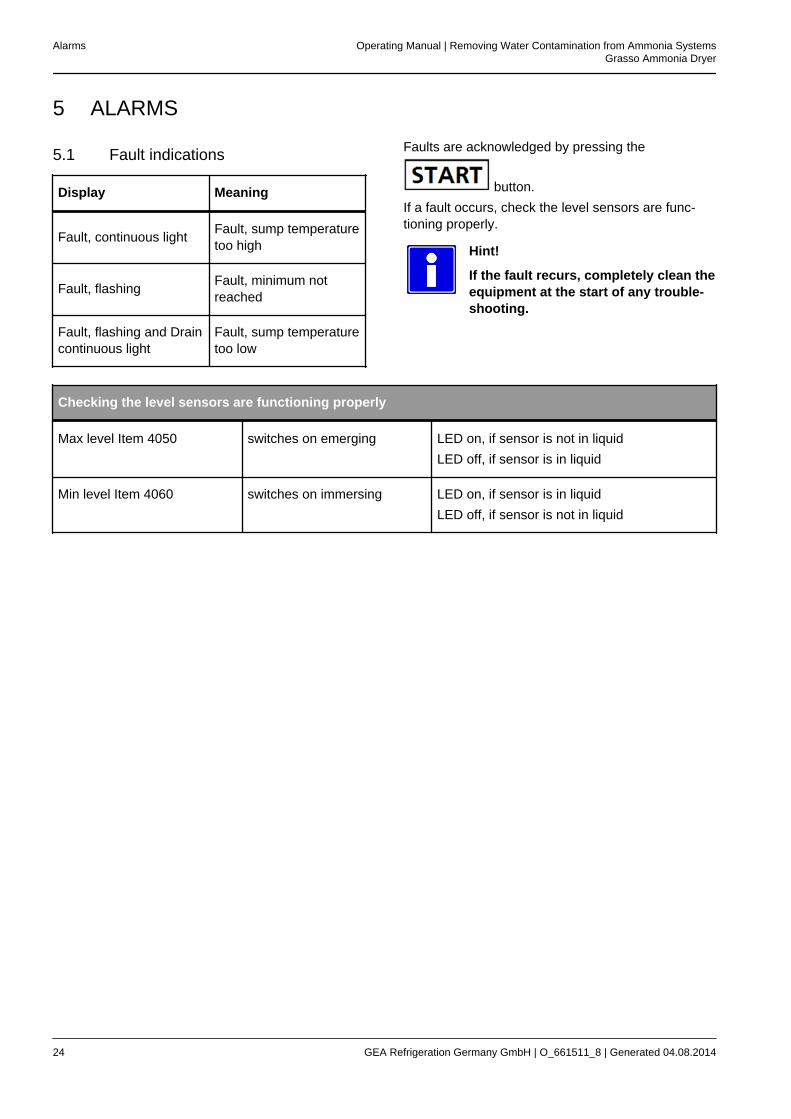
5 ALARMS
5.1 Fault indications
Display Meaning
Fault, continuous light Fault, sump temperaturetoo high
Fault, flashing Fault, minimum notreached
Fault, flashing and Draincontinuous light
Fault, sump temperaturetoo low
Faults are acknowledged by pressing the
button.If a fault occurs, check the level sensors are func-tioning properly.
Hint!
If the fault recurs, completely clean theequipment at the start of any trouble-shooting.
Checking the level sensors are functioning properly
Max level Item 4050 switches on emerging LED on, if sensor is not in liquidLED off, if sensor is in liquid
Min level Item 4060 switches on immersing LED on, if sensor is in liquidLED off, if sensor is not in liquid
Alarms Operating Manual | Removing Water Contamination from Ammonia SystemsGrasso Ammonia Dryer
24 GEA Refrigeration Germany GmbH | O_661511_8 | Generated 04.08.2014
6 TEST PROCEDURE
6.1 Procedure to determine the watercontent in ammonia refrigeratingcycles (measurement)
1. Where can the sample be taken?
– On the discharge side of the refrigerantpump downstream of the low-pressurereceiver or
– at the service valve, at the evaporator inlet
2. Under which conditions can the sample betaken?
– The system is running in normal operatingmode
– No ice or condensate on the service valve
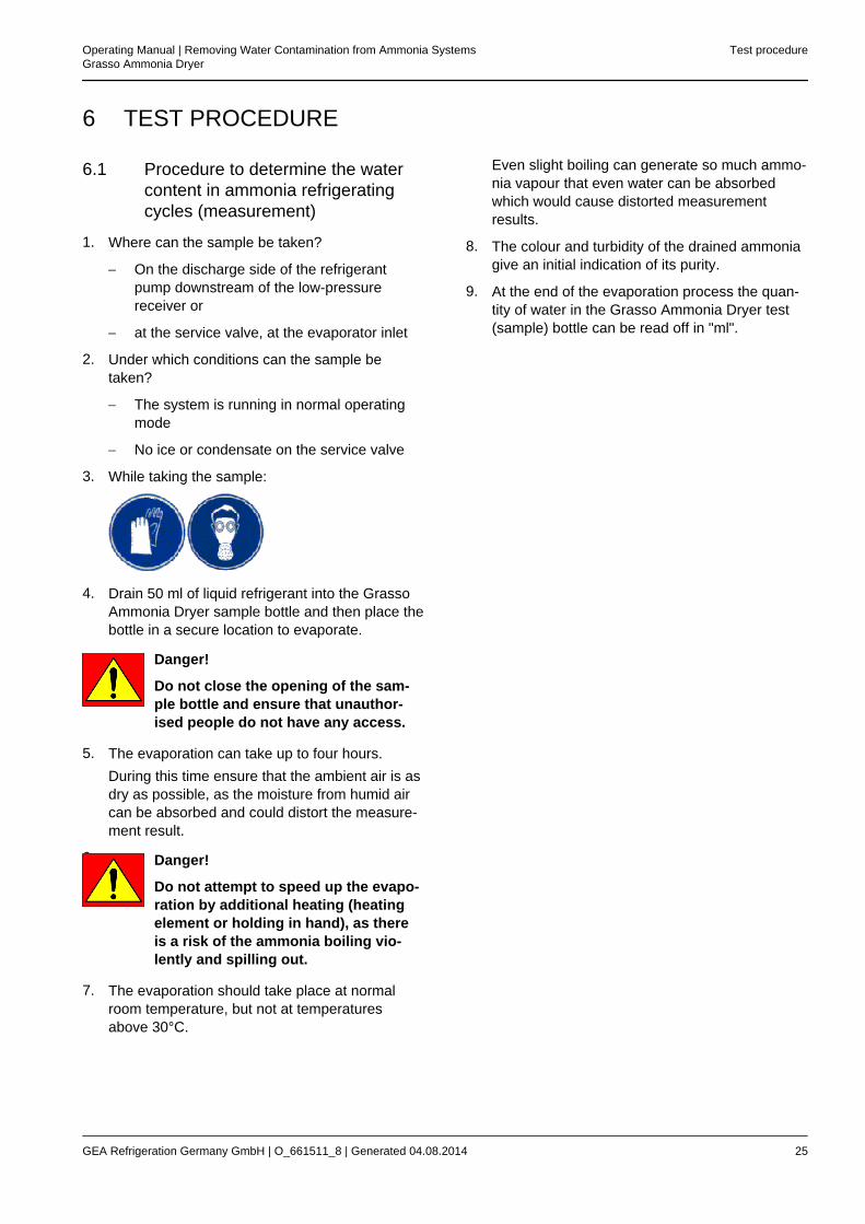
3. While taking the sample:
4. Drain 50 ml of liquid refrigerant into the GrassoAmmonia Dryer sample bottle and then place thebottle in a secure location to evaporate.
Danger!
Do not close the opening of the sam-ple bottle and ensure that unauthor-ised people do not have any access.
5. The evaporation can take up to four hours.During this time ensure that the ambient air is asdry as possible, as the moisture from humid aircan be absorbed and could distort the measure-ment result.
6. Danger!
Do not attempt to speed up the evapo-ration by additional heating (heatingelement or holding in hand), as thereis a risk of the ammonia boiling vio-lently and spilling out.
7. The evaporation should take place at normalroom temperature, but not at temperaturesabove 30°C.
Even slight boiling can generate so much ammo-nia vapour that even water can be absorbedwhich would cause distorted measurementresults.
8. The colour and turbidity of the drained ammoniagive an initial indication of its purity.
9. At the end of the evaporation process the quan-tity of water in the Grasso Ammonia Dryer test(sample) bottle can be read off in "ml".
Operating Manual | Removing Water Contamination from Ammonia SystemsGrasso Ammonia Dryer
Test procedure
GEA Refrigeration Germany GmbH | O_661511_8 | Generated 04.08.2014 25
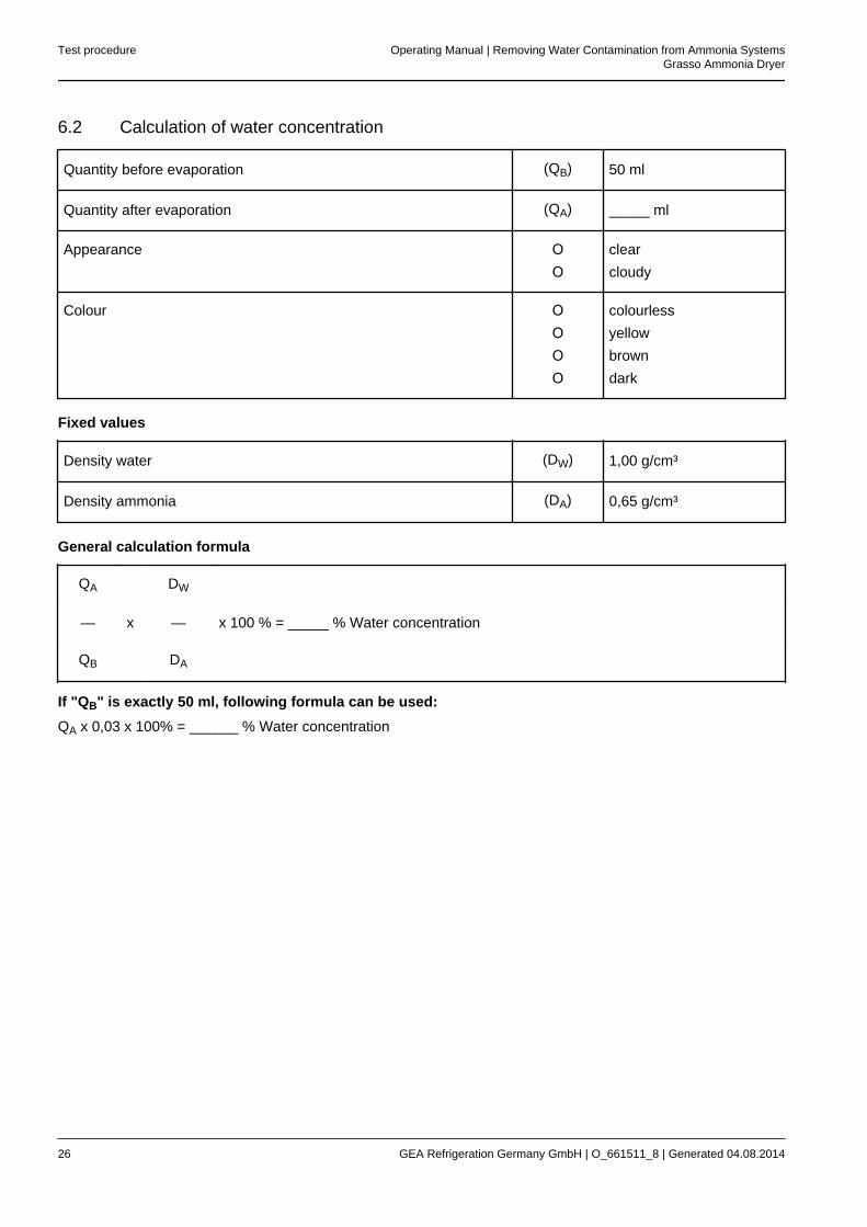
6.2 Calculation of water concentration
Quantity before evaporation (QB) 50 ml
Quantity after evaporation (QA) _____ ml
Appearance ΟΟ
clearcloudy
Colour ΟΟΟΟ
colourlessyellowbrowndark
Fixed values
Density water (DW) 1,00 g/cm³
Density ammonia (DA) 0,65 g/cm³
General calculation formula
QA DW
— x — x 100 % = _____ % Water concentration
QB DA
If "QB" is exactly 50 ml, following formula can be used:QA x 0,03 x 100% = ______ % Water concentration
Test procedure Operating Manual | Removing Water Contamination from Ammonia SystemsGrasso Ammonia Dryer
26 GEA Refrigeration Germany GmbH | O_661511_8 | Generated 04.08.2014
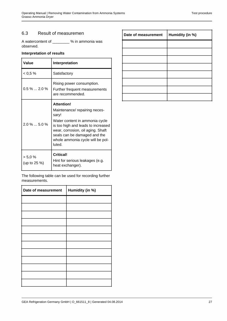
6.3 Result of measuremen
A watercontent of ________ % in ammonia wasobserved.
Interpretation of results
Value Interpretation
< 0,5 % Satisfactory
0.5 % ... 2.0 %Rising power consumption.Further frequent measurementsare recommended.
2.0 % ... 5.0 %
Attention!Maintenance/ repairing neces-sary!Water content in ammonia cycleis too high and leads to increasedwear, corrosion, oil aging. Shaftseals can be damaged and thewhole ammonia cycle will be pol-luted.
> 5,0 %(up to 25 %)
Critical!Hint for serious leakages (e.g.heat exchanger).
The following table can be used for recording furthermeasurements.
Date of measurement Humidity (in %)
Date of measurement Humidity (in %)
Operating Manual | Removing Water Contamination from Ammonia SystemsGrasso Ammonia Dryer
Test procedure
GEA Refrigeration Germany GmbH | O_661511_8 | Generated 04.08.2014 27