remotely operated vehicles for use in marine benthic...
TRANSCRIPT
Marine Monitoring Platform Guidelines
Remotely Operated Vehicles for use in marine benthic monitoring
© JNCC 2018
ISSN 2517-7605
Recommended citation:
JNCC, 2018. Remotely Operated Vehicles for use in marine benthic monitoring. Marine Monitoring Platform Guidelines No.1. JNCC, Peterborough. ISSN 2517-7605.
Authors: Tillin, H.M.*a, Luff, A.a, Graham, G.a, Wadsworth, T.b, Shirley, M.a, Dando, P.a, Baldock, L.a & van Rein, H.*c
a Marine Biological Association of the United Kingdom, The Laboratory, Citadel Hill, Plymouth, PL1 2PB, UK. b Hydrobotix, 35a Eggbuckland Road, Plymouth, PL3 5HF, UK. c Joint Nature Conservation Committee, Monkstone House, City Road, Peterborough, PE1 1JY, UK.
* Contact: H. Tillin ([email protected]) and H. van Rein ([email protected])
JNCC would like to thank the external reviewers, Dr Kerry Howell (University of Plymouth), Dr Leigh Marsh and David Turner (NOC), for their constructive comments which have helped enrich the guidelines. We are also grateful to the members of the Project Steering Group for their support, comments and guidance throughout the production of these guidelines. They include Dr David Donnan (Scottish Natural Heritage), Tim Mackie and Joe Breen (Department of Agriculture, Environment and Rural Affairs) and Melisa Vural and Hayley Hinchen (Joint Nature Conservation Committee).
Photograph acknowledgements: images supplied by Saab (www.seaeye.com), Leigh Marsh (NOC[1]), Josh Davison (MBA) and Tim Mackie (DAERA[2]), Georgios Kazanidis (University of Edinburgh), Marzia Bo (Università degli Studi di Genova).
1 National Oceanography Centre (NOC): https://noc.ac.uk/ 2 Department of Agriculture, Environment and Rural Affairs (DAERA): https://www.daera-ni.gov.uk/

Contents
Overview ........................................................................................................................................ 1
Logistics ........................................................................................................................................ 3
A. Equipment ............................................................................................................................ 3
B. Vessel Considerations for ROV operations ........................................................................... 8
C. Personnel Requirements ...................................................................................................... 8
D. Survey planning.................................................................................................................... 9
E. Risk Assessment ................................................................................................................ 10
Operational guidelines ............................................................................................................... 10
A. Surface preparation (All ROV classes) ............................................................................... 10
B. Deployment ........................................................................................................................ 11
C. Survey ................................................................................................................................ 11
D. Recovery ............................................................................................................................ 12
E. Stowage ............................................................................................................................. 12
Interpretation guidelines ............................................................................................................ 13
Quality assurance measures...................................................................................................... 13
Data products .............................................................................................................................. 13
Data management ..................................................................................................................... 13
References .................................................................................................................................. 15
Annex 1. Additional survey planning considerations and health and safety ................................... 18
Annex 2. Survey costs and time ................................................................................................... 20
Annex 3. Alternative options for surveying/sampling .................................................................... 22
Marine Monitoring Platform Guidelines
1
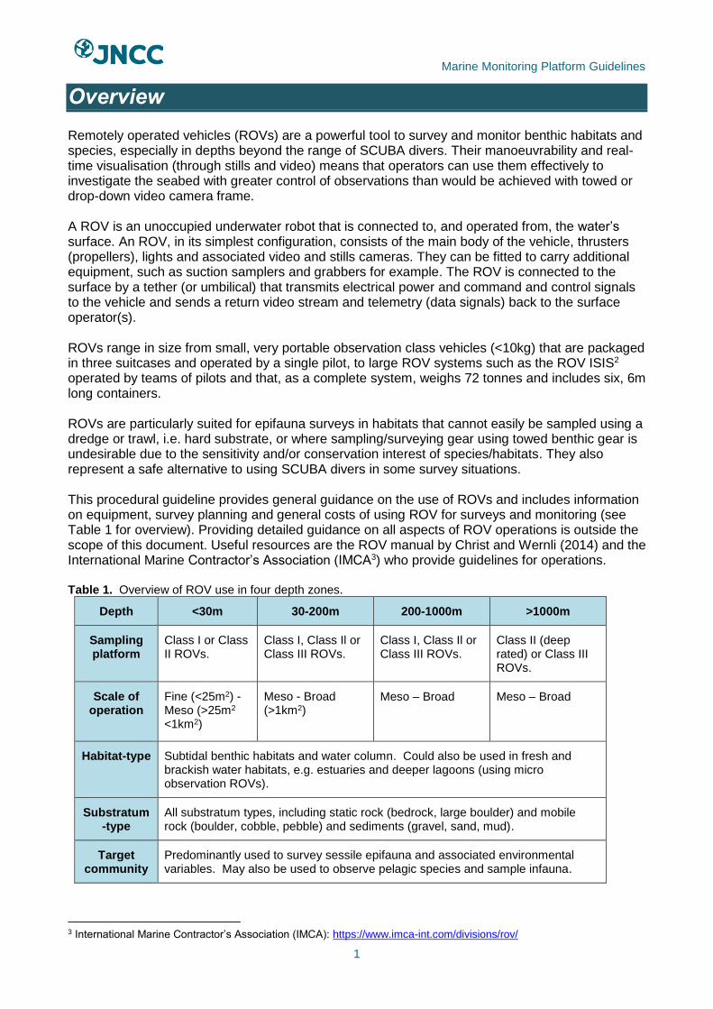
Overview Remotely operated vehicles (ROVs) are a powerful tool to survey and monitor benthic habitats and species, especially in depths beyond the range of SCUBA divers. Their manoeuvrability and real-time visualisation (through stills and video) means that operators can use them effectively to investigate the seabed with greater control of observations than would be achieved with towed or drop-down video camera frame. A ROV is an unoccupied underwater robot that is connected to, and operated from, the water’s surface. An ROV, in its simplest configuration, consists of the main body of the vehicle, thrusters (propellers), lights and associated video and stills cameras. They can be fitted to carry additional equipment, such as suction samplers and grabbers for example. The ROV is connected to the surface by a tether (or umbilical) that transmits electrical power and command and control signals to the vehicle and sends a return video stream and telemetry (data signals) back to the surface operator(s). ROVs range in size from small, very portable observation class vehicles (<10kg) that are packaged in three suitcases and operated by a single pilot, to large ROV systems such as the ROV ISIS2 operated by teams of pilots and that, as a complete system, weighs 72 tonnes and includes six, 6m long containers. ROVs are particularly suited for epifauna surveys in habitats that cannot easily be sampled using a dredge or trawl, i.e. hard substrate, or where sampling/surveying gear using towed benthic gear is undesirable due to the sensitivity and/or conservation interest of species/habitats. They also represent a safe alternative to using SCUBA divers in some survey situations. This procedural guideline provides general guidance on the use of ROVs and includes information on equipment, survey planning and general costs of using ROV for surveys and monitoring (see Table 1 for overview). Providing detailed guidance on all aspects of ROV operations is outside the scope of this document. Useful resources are the ROV manual by Christ and Wernli (2014) and the International Marine Contractor’s Association (IMCA3) who provide guidelines for operations. Table 1. Overview of ROV use in four depth zones.
Depth <30m 30-200m 200-1000m >1000m
Sampling platform
Class I or Class II ROVs.
Class I, Class Il or Class III ROVs.
Class I, Class Il or Class III ROVs.
Class II (deep rated) or Class III ROVs.
Scale of operation
Fine (<25m2) - Meso (>25m2 <1km2)
Meso - Broad (>1km2)
Meso – Broad Meso – Broad
Habitat-type Subtidal benthic habitats and water column. Could also be used in fresh and brackish water habitats, e.g. estuaries and deeper lagoons (using micro observation ROVs).
Substratum-type
All substratum types, including static rock (bedrock, large boulder) and mobile rock (boulder, cobble, pebble) and sediments (gravel, sand, mud).
Target community
Predominantly used to survey sessile epifauna and associated environmental variables. May also be used to observe pelagic species and sample infauna.
3 International Marine Contractor’s Association (IMCA): https://www.imca-int.com/divisions/rov/

Marine Monitoring Platform Guidelines
2
Samples produced
Qualitative and quantitative survey data includes scaled still and video footage of macro- and megafauna, observations of lebensspuren (footage of tracks, burrows etc.) and habitat/substrate descriptions. Multibeam survey data. Physical samples can include water samples, samples of sediment, rocks, and parts of, or whole organisms.
Data products
Video and stills images of species and habitats, environmental data (including temperature, salinity, depth, oxygen etc.), vehicle telemetry (including navigation, altitude (e.g. pitch, roll, heading, altitude etc.), high resolution multibeam survey.
Cost per day4
£2,400-7,000 £4,500-36,000 (Class I or Class II ROV)
£33,000-55,000 >£50,000
Advantages of ROVs Limitations of ROVs
An ROV captures continual footage streamed in real-time onboard the vessel so surveys can be reactive. More manoeuvrable than landers, drop cameras and towed sleds (Bergman et al 2009) and Autonomous Underwater Vehicles (AUVs). Can survey complex terrain, otherwise inaccessible by towed gear and grabs (Boyd et al 2006; van Rein et al 2009; Saunders et al 2011). A range of ROVs and accessories can be hired to achieve a wide variety of surveying and sampling goals. The capability to collect physical samples, such as parts of emergent epifauna, allows ground-truthing of observations and, with associated imagery, allows understanding of context in which samples were collected. Reduces survey risk when compared with diving. Can reach depths inaccessible to divers (van Rein et al 2009) and survey longer, ascend and descend repeatedly (unlike divers), and visit multiple stations in a survey day (Andaloro et al 2013; Boavida et al 2016). Can be used in biogenic habitats and areas with fragile epifauna, such as coral (Guinan et al 2009) and sponge rich habitats (Cook et al 2008; Iversen et al 2015).
ROVs are more expensive to run than towed sampling platforms and are more prone to equipment failure/down time during surveys. Power is a limitation for the smaller Class I ROVs and their performance reduces with increased depth (due to tether drag), high current velocities and adverse weather conditions (Bates et al 2004; Boavida et al 2016; Guinan et al 2009). ROVs are less rugged, and their area coverage per hour is much less than drop cameras and towed sleds (Eletheriou 2013). Risk of tether entanglement and snagging in vessel thrusters and obstacles such as discarded fishing gear. As with all sampling platforms introducing light and movement to marine habitats, the ROV will affect the local environment and associated species. Observations may not be representative of normal species community and behaviour as a result (Bamstedt et al 2003).
4 Estimated cost based on planning, ROV and vessel hire, planning and day rate for on-board scientist/survey manager. Consumables, processing of samples and reporting are not included.
Marine Monitoring Platform Guidelines
3
Logistics
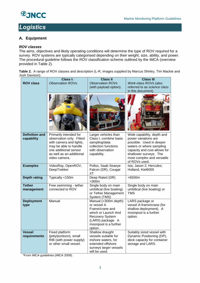
A. Equipment ROV classes The aims, objectives and likely operating conditions will determine the type of ROV required for a survey. ROV systems are typically categorised depending on their weight, size, ability, and power. The procedural guideline follows the ROV classification scheme outlined by the IMCA (overview provided in Table 2).
Table 2. A range of ROV classes and description (L-R, images supplied by Marcus Shirley, Tim Mackie and Josh Davison).
ROV class
Class I: Observation ROVs.
Class II Observation ROVs (with payload option).
Class III Work-class ROVs (also referred to as science class in this document).
Definition and capability
Primarily intended for observation only. Fitted with camera and lights, may be able to handle one additional sensor as well as an additional video camera.
Larger vehicles than Class I, combine basic sampling/data collection functions with observation capability.
Wide capability, depth and power variations are possible. Used in deeper waters or where sampling capacity and cost allows for shallower surveys. The most complex and versatile of ROVs used.
Examples VideoRay, OpenROV, DeepTrekker
Pollox, Saab Seaeye Falcon (DR), Cougar XT
Isis; Jason 2; Hercules; Holland, Kiel6000
Depth rating Typically <150m Deep Rated (DR) >300m
<6500m
Tether management
Free swimming - tether connected to ROV
Single body on main umbilical (live boating) or Tether Management System (TMS)
Single body on main umbilical (live boating) or TMS
Deployment type
Manual Manual (<300m depth) or vessel A Frame/crane and winch or Launch And Recovery System (LARS) package. A moonpool is a further option.
LARS package or vessel A-frame/crane (for shallow deployment). A moonpool is a further option.
Vessel requirements
Fixed platform (jetty/pontoon), small RIB (with power supply) or other small vessel.
Shallow draught vessels suitable for inshore waters, for extended offshore surveys larger vessels will be used.
Suitably sized vessel with Dynamic Positioning (DP), deck capacity for container storage and LARS.
*From IMCA guidelines (IMCA 2009).
Marine Monitoring Platform Guidelines
4
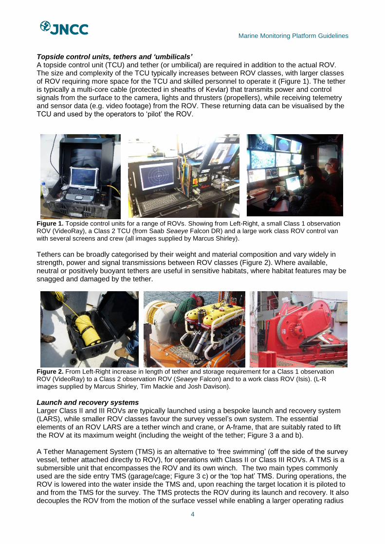
Topside control units, tethers and ‘umbilicals’ A topside control unit (TCU) and tether (or umbilical) are required in addition to the actual ROV. The size and complexity of the TCU typically increases between ROV classes, with larger classes of ROV requiring more space for the TCU and skilled personnel to operate it (Figure 1). The tether is typically a multi-core cable (protected in sheaths of Kevlar) that transmits power and control signals from the surface to the camera, lights and thrusters (propellers), while receiving telemetry and sensor data (e.g. video footage) from the ROV. These returning data can be visualised by the TCU and used by the operators to ‘pilot’ the ROV.
Figure 1. Topside control units for a range of ROVs. Showing from Left-Right, a small Class 1 observation ROV (VideoRay), a Class 2 TCU (from Saab Seaeye Falcon DR) and a large work class ROV control van with several screens and crew (all images supplied by Marcus Shirley).
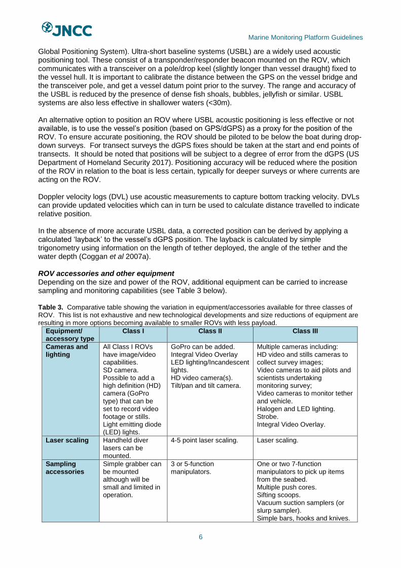
Tethers can be broadly categorised by their weight and material composition and vary widely in strength, power and signal transmissions between ROV classes (Figure 2). Where available, neutral or positively buoyant tethers are useful in sensitive habitats, where habitat features may be snagged and damaged by the tether.
Figure 2. From Left-Right increase in length of tether and storage requirement for a Class 1 observation ROV (VideoRay) to a Class 2 observation ROV (Seaeye Falcon) and to a work class ROV (Isis). (L-R images supplied by Marcus Shirley, Tim Mackie and Josh Davison).
Launch and recovery systems Larger Class II and III ROVs are typically launched using a bespoke launch and recovery system (LARS), while smaller ROV classes favour the survey vessel’s own system. The essential elements of an ROV LARS are a tether winch and crane, or A-frame, that are suitably rated to lift the ROV at its maximum weight (including the weight of the tether; Figure 3 a and b). A Tether Management System (TMS) is an alternative to ‘free swimming’ (off the side of the survey vessel, tether attached directly to ROV), for operations with Class II or Class III ROVs. A TMS is a submersible unit that encompasses the ROV and its own winch. The two main types commonly used are the side entry TMS (garage/cage; Figure 3 c) or the ‘top hat’ TMS. During operations, the ROV is lowered into the water inside the TMS and, upon reaching the target location it is piloted to and from the TMS for the survey. The TMS protects the ROV during its launch and recovery. It also decouples the ROV from the motion of the surface vessel while enabling a larger operating radius

Marine Monitoring Platform Guidelines
5
at the target location during a survey. TMS garages can be modified to carry tools and store samples.
a)
b)
c)
Figure 3. ROV launch, recovery systems and tether management systems. Custom built ROV Launch and Recovery System (LARS) showing: a) folded LARS for Class II ROV (Saab Seaeye) and b) extended LARS. c) Garage type Tether Management System (TMS; Saab Seaeye).
Figure 4 (below) provides a diagram of all components of an ROV system working together. This configuration is not standard, e.g. a small ROV is manually deployed, but the TCU, tether and ROV are used in all systems (image supplied by Saab Seaeye5).
Figure 4. Diagram showing the main elements of an ROV system, the exact configuration and requirements will vary depending on ROV Class, the example shown is for a Class II ROV (image supplied by Saab Seaeye).
Navigation and positioning systems To achieve accurate positioning of an ROV, acoustic telemetry is recommended to navigate and track the vehicle relative to the surface ship’s satellite positioning system (GPS/dGPS (differential
5 www.seaeye.com
Marine Monitoring Platform Guidelines
6
Global Positioning System). Ultra-short baseline systems (USBL) are a widely used acoustic positioning tool. These consist of a transponder/responder beacon mounted on the ROV, which communicates with a transceiver on a pole/drop keel (slightly longer than vessel draught) fixed to the vessel hull. It is important to calibrate the distance between the GPS on the vessel bridge and the transceiver pole, and get a vessel datum point prior to the survey. The range and accuracy of the USBL is reduced by the presence of dense fish shoals, bubbles, jellyfish or similar. USBL systems are also less effective in shallower waters (<30m). An alternative option to position an ROV where USBL acoustic positioning is less effective or not available, is to use the vessel’s position (based on GPS/dGPS) as a proxy for the position of the ROV. To ensure accurate positioning, the ROV should be piloted to be below the boat during drop-down surveys. For transect surveys the dGPS fixes should be taken at the start and end points of transects. It should be noted that positions will be subject to a degree of error from the dGPS (US Department of Homeland Security 2017). Positioning accuracy will be reduced where the position of the ROV in relation to the boat is less certain, typically for deeper surveys or where currents are acting on the ROV. Doppler velocity logs (DVL) use acoustic measurements to capture bottom tracking velocity. DVLs can provide updated velocities which can in turn be used to calculate distance travelled to indicate relative position. In the absence of more accurate USBL data, a corrected position can be derived by applying a calculated ‘layback’ to the vessel’s dGPS position. The layback is calculated by simple trigonometry using information on the length of tether deployed, the angle of the tether and the water depth (Coggan et al 2007a). ROV accessories and other equipment Depending on the size and power of the ROV, additional equipment can be carried to increase sampling and monitoring capabilities (see Table 3 below). Table 3. Comparative table showing the variation in equipment/accessories available for three classes of ROV. This list is not exhaustive and new technological developments and size reductions of equipment are resulting in more options becoming available to smaller ROVs with less payload.
Equipment/ accessory type
Class I
Class II Class III
Cameras and lighting
All Class I ROVs have image/video capabilities. SD camera. Possible to add a high definition (HD) camera (GoPro type) that can be set to record video footage or stills. Light emitting diode (LED) lights.
GoPro can be added. Integral Video Overlay LED lighting/Incandescent lights. HD video camera(s). Tilt/pan and tilt camera.
Multiple cameras including: HD video and stills cameras to collect survey images; Video cameras to aid pilots and scientists undertaking monitoring survey; Video cameras to monitor tether and vehicle. Halogen and LED lighting. Strobe. Integral Video Overlay.
Laser scaling Handheld diver lasers can be mounted.
4-5 point laser scaling. Laser scaling.
Sampling accessories
Simple grabber can be mounted although will be small and limited in operation.
3 or 5-function manipulators.
One or two 7-function manipulators to pick up items from the seabed. Multiple push cores. Sifting scoops. Vacuum suction samplers (or slurp sampler). Simple bars, hooks and knives.
Marine Monitoring Platform Guidelines
7
Other tools designed for specific survey objectives.
Sample storage
No sample storage. Tooling skid. TMS garage can be modified to carry tools and offer storage facilities/space for small experimental set up and deployments.
ROV can incorporate a sample sled that includes bioboxes for containing organisms, geoboxes for stones. Retractable drawers.
Navigation and positioning
Possible to add ultra-short baseline system (USBL) beacon.
Auto heading, Autodepth. Altimeter. Compass. USBL beacon. Doppler Velocity Logs (DVLs).
Auto heading, Autodepth. Altimeter. Compass. USBL beacon, scanning sonars; USBL transponder. DVL.
Environmental sensor packages
Not usually. Current meter. Conductivity temperature depth (CTD) sensor. Sidescan and multibeam sonars.
CTD. Acoustic Doppler Current Profilers (ADCPs). Sidescan and multibeam sonars.
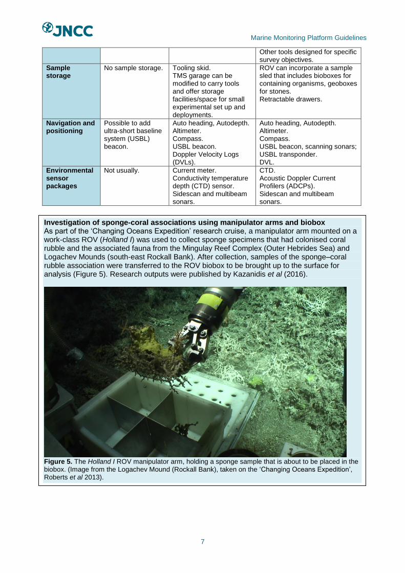
Investigation of sponge-coral associations using manipulator arms and biobox As part of the ‘Changing Oceans Expedition’ research cruise, a manipulator arm mounted on a work-class ROV (Holland I) was used to collect sponge specimens that had colonised coral rubble and the associated fauna from the Mingulay Reef Complex (Outer Hebrides Sea) and Logachev Mounds (south-east Rockall Bank). After collection, samples of the sponge–coral rubble association were transferred to the ROV biobox to be brought up to the surface for analysis (Figure 5). Research outputs were published by Kazanidis et al (2016).
Figure 5. The Holland I ROV manipulator arm, holding a sponge sample that is about to be placed in the biobox. (Image from the Logachev Mound (Rockall Bank), taken on the ‘Changing Oceans Expedition’, Roberts et al 2013).
Marine Monitoring Platform Guidelines
8
B. Vessel Considerations for ROV operations ROV equipment can be deployed from a wide range of vessels and static platforms (offshore infrastructure/coastal structures). The following key points should be considered when selecting a suitable vessel:
• Is the vessel suitable and capable for the area of deployment (See Table 4)?
• Does the vessel have the manoeuvring capability to carry out the survey plan?
• Does the vessel have the correct power supply for running the equipment?
• Is there suitable deck and sheltered cabin space for accommodating equipment and working comfortably and safely?
• Are there means for safe launching and recovery of the ROV?
• If the ROV is deployed and recovered manually is the freeboard of suitable height or are there hatches in the gunwales or transom that can be used?
• Does the vessel carry sufficient safety equipment and comply with current workboat codes of practice?
• If hired, do the vessel hire costs cover insurance, fuel or other costs such as winch operator?
• Are the skipper and crew competent (trained and/or experienced) in similar operations e.g. anchoring and positioning of vessel, holding courses, operating winches?
Table 4. Outline key vessel considerations for different operating environments.
Environment Vessel considerations
Strong tidal waters Dynamic positioning, winch capacity
Inshore waters (<12NM) Shallow draught, highly manoeuvrable, winch capacity, size
Offshore waters (>12NM)
Dynamic positioning, stability, winch capacity, size
Coastal waters Shallow draught, highly manoeuvrable, stability, winch capacity
Pontoons and Jetties N/A
C. Personnel Requirements The person with responsibility for the role of survey planning (e.g. survey manager) is required to ensure all operational stages are planned and safely executed. They should be competent (skilled and experienced) to carry out survey planning and management. For planned operations in <30m water depth, a survey manager familiar with towed vehicle benthic operations is required as a minimum. For more complex, demanding survey operations using Class II and Class III ROVs, the survey manager should have previous experience of seagoing surveys with similar vehicles, vessels and operations, as well as in their planning and assessment of risk. It is recommended that the survey manager/fully-briefed scientific staff are present on operations to advise and modify plans as necessary. ROV Pilots Competent ROV pilots are required to ensure a high-quality survey. Previous experience in the planned survey operation is preferred as ROV pilots experienced in other types of operation won’t necessarily understand the specific needs of scientific ROV dives and may lack experience in manipulating organisms / obtaining samples effectively and efficiently.
The amount of experience required to be a competent ROV pilot varies among pilots based on their aptitude and skills (Table 5). Some ROV pilots may have an IMCA logbook to record flights but formal training isn’t standard practice or a requirement across the industry. When commissioning an ROV pilot, experience in the make and model of ROV being used is important. The ability to carry out operations under difficult conditions, such as strong currents or limited visibility should be checked, depending on likely survey conditions.
Marine Monitoring Platform Guidelines
9
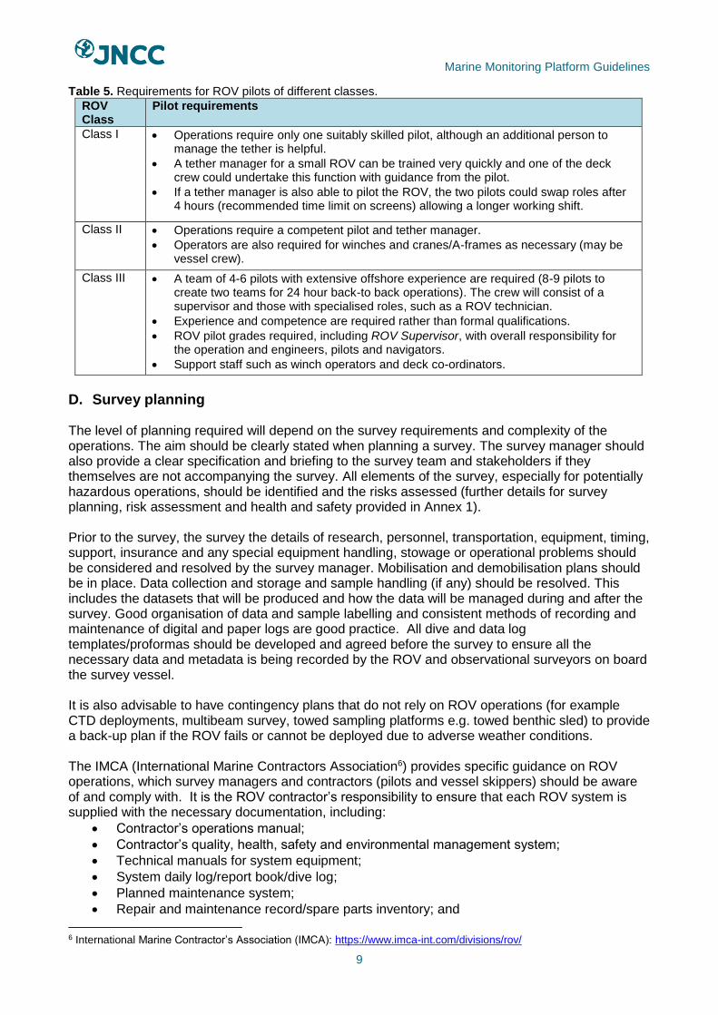
Table 5. Requirements for ROV pilots of different classes.
ROV Class
Pilot requirements
Class I • Operations require only one suitably skilled pilot, although an additional person to manage the tether is helpful.
• A tether manager for a small ROV can be trained very quickly and one of the deck crew could undertake this function with guidance from the pilot.
• If a tether manager is also able to pilot the ROV, the two pilots could swap roles after 4 hours (recommended time limit on screens) allowing a longer working shift.
Class II • Operations require a competent pilot and tether manager.
• Operators are also required for winches and cranes/A-frames as necessary (may be vessel crew).
Class III • A team of 4-6 pilots with extensive offshore experience are required (8-9 pilots to create two teams for 24 hour back-to back operations). The crew will consist of a supervisor and those with specialised roles, such as a ROV technician.
• Experience and competence are required rather than formal qualifications.
• ROV pilot grades required, including ROV Supervisor, with overall responsibility for the operation and engineers, pilots and navigators.
• Support staff such as winch operators and deck co-ordinators.
D. Survey planning The level of planning required will depend on the survey requirements and complexity of the operations. The aim should be clearly stated when planning a survey. The survey manager should also provide a clear specification and briefing to the survey team and stakeholders if they themselves are not accompanying the survey. All elements of the survey, especially for potentially hazardous operations, should be identified and the risks assessed (further details for survey planning, risk assessment and health and safety provided in Annex 1). Prior to the survey, the survey the details of research, personnel, transportation, equipment, timing, support, insurance and any special equipment handling, stowage or operational problems should be considered and resolved by the survey manager. Mobilisation and demobilisation plans should be in place. Data collection and storage and sample handling (if any) should be resolved. This includes the datasets that will be produced and how the data will be managed during and after the survey. Good organisation of data and sample labelling and consistent methods of recording and maintenance of digital and paper logs are good practice. All dive and data log templates/proformas should be developed and agreed before the survey to ensure all the necessary data and metadata is being recorded by the ROV and observational surveyors on board the survey vessel. It is also advisable to have contingency plans that do not rely on ROV operations (for example CTD deployments, multibeam survey, towed sampling platforms e.g. towed benthic sled) to provide a back-up plan if the ROV fails or cannot be deployed due to adverse weather conditions. The IMCA (International Marine Contractors Association6) provides specific guidance on ROV operations, which survey managers and contractors (pilots and vessel skippers) should be aware of and comply with. It is the ROV contractor’s responsibility to ensure that each ROV system is supplied with the necessary documentation, including:
• Contractor’s operations manual;
• Contractor’s quality, health, safety and environmental management system;
• Technical manuals for system equipment;
• System daily log/report book/dive log;
• Planned maintenance system;
• Repair and maintenance record/spare parts inventory; and
6 International Marine Contractor’s Association (IMCA): https://www.imca-int.com/divisions/rov/

Marine Monitoring Platform Guidelines
10
• Pre- and post-dive checklists.
E. Risk Assessment Risk assessment guidance for ROV operations is provided by the IMCA (IMCA 2009). The survey plans and operational risk assessment should address the risk from:
• ROV systems, including the ROV itself, winches and A frames, cranes;
• Electrical hazards, particularly from electric shock;
• Tether handling, including risk of entanglement in vessel thrusters or debris with risk of damage to ROV, vessel and injury of deck personnel;
• Vehicle recovery following damage/breakdown;
• Reduced observer situational awareness during survey operations; and
• ROV operations and other survey considerations (e.g. divers working with or in the vicinity of ROVs), including entanglement with tether, physical contact and electrical hazards.
Electrical hazards and subsequent fire risk are an important factor with most ROV use. Health and Safety briefings need to include this and all crew should be aware of how to isolate supply/generators and first aiders should refresh understanding of responding to/treating electrical shock. It is good practice to have additional fire extinguishers to hand (of appropriate type to deal with electrical and fuel related fires).
Operational guidelines The operating procedures should normally consist of both the ROV contractor’s standard operating rules together with any site-specific requirements and procedures. Contingency procedures for any foreseeable emergencies are also required (IMCA 2009).
A. Surface preparation (All ROV classes) If the ship carries multibeam sonar, then traverses over the survey area will allow the detection and avoidance of any obstacles that could snag the ROV (Huvenne et al 2016). Alternatively, the ROV may be used to survey the area visually or, if equipped, using the ROV’s scanning sonars (aids detection and avoidance of obstacles). Pre-dive checks of the ROV should be undertaken, typically carried out by ROV pilots/technicians following a checklist that includes:
• A visual and physical inspection;
• Checking of command controls; and
• Vehicle response and data displays and ancillary tools. The camera imaging, lighting and recording modes should be adjusted to ensure that the highest quality image can be maintained throughout the dive. Testing of the cameras and lighting must ensure that well-lit, high-resolution pictures can be obtained while the ROV is in flight (Hitchin et al 2015). Any unnecessary equipment should be removed from the ROV and the ballast of the ROV should be slightly positive (Christ & Wernli 2007). The recording equipment and logs should be switched on before the ROV enters the water, once the vessel is positioned over the survey area. If additional equipment is being used such as a CTD, it is critical to also ensure the internal clock is synchronised with the ships GPS system and camera clock.
Marine Monitoring Platform Guidelines
11
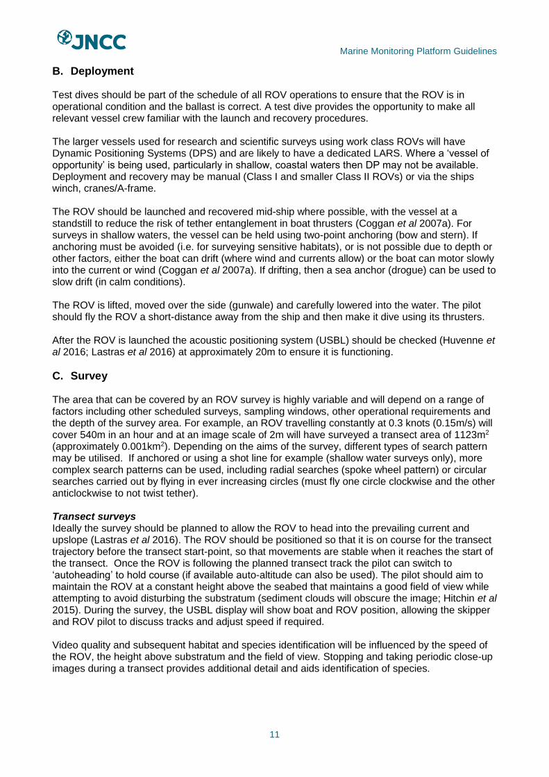
B. Deployment Test dives should be part of the schedule of all ROV operations to ensure that the ROV is in operational condition and the ballast is correct. A test dive provides the opportunity to make all relevant vessel crew familiar with the launch and recovery procedures. The larger vessels used for research and scientific surveys using work class ROVs will have Dynamic Positioning Systems (DPS) and are likely to have a dedicated LARS. Where a ‘vessel of opportunity’ is being used, particularly in shallow, coastal waters then DP may not be available. Deployment and recovery may be manual (Class I and smaller Class II ROVs) or via the ships winch, cranes/A-frame. The ROV should be launched and recovered mid-ship where possible, with the vessel at a standstill to reduce the risk of tether entanglement in boat thrusters (Coggan et al 2007a). For surveys in shallow waters, the vessel can be held using two-point anchoring (bow and stern). If anchoring must be avoided (i.e. for surveying sensitive habitats), or is not possible due to depth or other factors, either the boat can drift (where wind and currents allow) or the boat can motor slowly into the current or wind (Coggan et al 2007a). If drifting, then a sea anchor (drogue) can be used to slow drift (in calm conditions). The ROV is lifted, moved over the side (gunwale) and carefully lowered into the water. The pilot should fly the ROV a short-distance away from the ship and then make it dive using its thrusters. After the ROV is launched the acoustic positioning system (USBL) should be checked (Huvenne et al 2016; Lastras et al 2016) at approximately 20m to ensure it is functioning.
C. Survey The area that can be covered by an ROV survey is highly variable and will depend on a range of factors including other scheduled surveys, sampling windows, other operational requirements and the depth of the survey area. For example, an ROV travelling constantly at 0.3 knots (0.15m/s) will cover 540m in an hour and at an image scale of 2m will have surveyed a transect area of 1123m2 (approximately 0.001km2). Depending on the aims of the survey, different types of search pattern may be utilised. If anchored or using a shot line for example (shallow water surveys only), more complex search patterns can be used, including radial searches (spoke wheel pattern) or circular searches carried out by flying in ever increasing circles (must fly one circle clockwise and the other anticlockwise to not twist tether). Transect surveys Ideally the survey should be planned to allow the ROV to head into the prevailing current and upslope (Lastras et al 2016). The ROV should be positioned so that it is on course for the transect trajectory before the transect start-point, so that movements are stable when it reaches the start of the transect. Once the ROV is following the planned transect track the pilot can switch to ‘autoheading’ to hold course (if available auto-altitude can also be used). The pilot should aim to maintain the ROV at a constant height above the seabed that maintains a good field of view while attempting to avoid disturbing the substratum (sediment clouds will obscure the image; Hitchin et al 2015). During the survey, the USBL display will show boat and ROV position, allowing the skipper and ROV pilot to discuss tracks and adjust speed if required. Video quality and subsequent habitat and species identification will be influenced by the speed of the ROV, the height above substratum and the field of view. Stopping and taking periodic close-up images during a transect provides additional detail and aids identification of species.

Marine Monitoring Platform Guidelines
12
D. Recovery For recovery, the vessel should be stationary by being either anchored or holding position using the DPS. Good practice is to surface the ROV away from the vessel (keeping clear of the vessel propellers). The tether should be taut to reduce tangling risk. Once at the surface the ROV should be flown to the vessel and recovered either manually or using the LARS or ships winch, cranes/A-frame used during the deployment. Alternatively, if a tether management system has been used the ROV will be flown to the TMS and the TMS recovered. The recovery requirements of the ROV in use should be adhered to, as specific ROV types will have different pre-ascent checks and procedures carried out before an ascent. For example, samples and tools will need to be stowed before the ascent.
E. Stowage Post-dive ROV checks are required. Equipment should be cleaned with freshwater before being stowed and samples processed and treated according to their requirements. The ROV logs, GoPro video data, standard video data and USBL data can be downloaded into a folder to record the logs for archiving. At the surface after recovery, the period of unloading usually needs to be rapid to prevent sample deterioration. Samples can be frozen or preserved/stored in other ways as required.
Coral morphometrics and fishing damage in the deep sea using ROV HD video As ROV technology has developed, video and camera surveys by ROV are proving to be a key tool to increase knowledge of the abundance and distribution patterns of deep water habitats including cold water corals, without damaging these sensitive habitats. The value of ROVs for this purpose (and by extension, other deeper or sensitive habitats) is illustrated by Bo et al (2015) who surveyed and sampled Mediterranean deep-sea corals using a class II ROV (Pollux). The ROV carried a digital camera, a strobe, a high definition video camera, a navigation camera, a depth sensor, compass, and three laser beams providing a 10cm scale and three jaw grabbers to collect portions from five colonies for morphological analysis (Bo et al 2015). The video image processing assessed density of characteristic species, identified morphometric characteristics of coral and provided quantitative estimates of fishing damage based on the number of frames showing lost gears (and direct damage to colonies by counting the number of entangled colonies; Figure 6). The images also allowed cohort groups to be identified to assess population structure.
Figure 6. Images of epifaunal communities entangled in fishing gear, taken by the ROV Pollox (Images supplied by Marzia Bo).

Marine Monitoring Platform Guidelines
13
Interpretation guidelines The data extracted from the ROV stills and video imagery depends on the survey objectives and targets. Most benthic habitat surveys aim to extract biotope, taxonomic and substratum information from the imagery and to enumerate this in some way (e.g. percentage cover, abundance, SACFOR, frequency of occurrence). Further imagery interpretation guidance is provided by the North East Atlantic Marine Biological Analytical Quality Control Scheme (NMBAQC; Turner et al 2016).
Quality assurance measures No specific quality assurance measures apply to ROV operations, however, the competence of personnel across survey planning, ROV and vessel operation and the selection of the correct ROV and equipment to meet survey aims and operating conditions will increase the likelihood of acquiring high quality survey data and monitoring results. Best practice guidelines for interpreting video and still image data of benthic substrata and epibenthic species have been developed and should be referred to (see Turner et al 2016 and Hitchin et al 2015). These guidelines form part of the epibiota component of the NMBAQC developed on behalf of the UK competent monitoring authorities to provide assessment of marine biological data contributing to UK national or European monitoring programmes.
Data products An ROV can collect qualitative and quantitative survey data, including physical samples of sediment, rocks, seawater and parts of / whole organisms (Table 6). Table 6. Types of data/samples collected by ROVs.
Equipment Data/samples collected
Video and still cameras, lights and laser scaling
Scaled still and video footage of epifauna, infauna (footage of tracks, burrows or exposed parts) and substrate type.
Physical samples Organisms, rock samples and stones, gas samples (for carbonate reefs).
USBL, DVL mapping software Mapping data (depth, position, topography).
Environmental sensors Conductivity (salinity), temperature, magnetic fields.
Push cores Sediment and infaunal community.
Multibeam and sidescan sonar Seabed mapping.
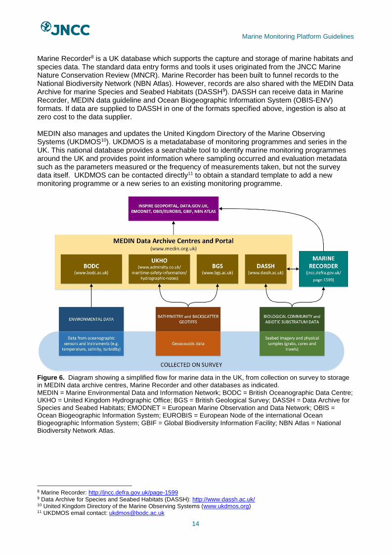
Data management Post processing, biological, environmental and acoustic data records should be appropriately archived. In the UK, the Marine Environmental Data and Information Network (MEDIN) promotes sharing of and improved access to marine data. To that end, MEDIN coordinates a network of Data Archive Centres (DACs) to secure long-term management of data, improve access through a central metadata portal and provide common standards7 (Figure 7). The MEDIN helpdesk can provide advice to data managers pre- and post-survey on metadata, as well as which DAC(s) are the most appropriate to use. The MEDIN helpdesk will also triage data to assess quality, ease of processing and ingestion. Appropriate data archived to MEDIN is shared among other relevant DACs. It is also automatically uploaded to a variety of other databases, including the European Marine Observation and Data Network (EMODNET).
7 MEDIN data guidelines: http://www.oceannet.org/marine_data_standards/medin_data_guidelines.html
Marine Monitoring Platform Guidelines
14
Marine Recorder8 is a UK database which supports the capture and storage of marine habitats and species data. The standard data entry forms and tools it uses originated from the JNCC Marine Nature Conservation Review (MNCR). Marine Recorder has been built to funnel records to the National Biodiversity Network (NBN Atlas). However, records are also shared with the MEDIN Data Archive for marine Species and Seabed Habitats (DASSH9). DASSH can receive data in Marine Recorder, MEDIN data guideline and Ocean Biogeographic Information System (OBIS-ENV) formats. If data are supplied to DASSH in one of the formats specified above, ingestion is also at zero cost to the data supplier. MEDIN also manages and updates the United Kingdom Directory of the Marine Observing Systems (UKDMOS10). UKDMOS is a metadatabase of monitoring programmes and series in the UK. This national database provides a searchable tool to identify marine monitoring programmes around the UK and provides point information where sampling occurred and evaluation metadata such as the parameters measured or the frequency of measurements taken, but not the survey data itself. UKDMOS can be contacted directly11 to obtain a standard template to add a new monitoring programme or a new series to an existing monitoring programme.
Figure 6. Diagram showing a simplified flow for marine data in the UK, from collection on survey to storage in MEDIN data archive centres, Marine Recorder and other databases as indicated. MEDIN = Marine Environmental Data and Information Network; BODC = British Oceanographic Data Centre; UKHO = United Kingdom Hydrographic Office; BGS = British Geological Survey; DASSH = Data Archive for Species and Seabed Habitats; EMODNET = European Marine Observation and Data Network; OBIS = Ocean Biogeographic Information System; EUROBIS = European Node of the international Ocean Biogeographic Information System; GBIF = Global Biodiversity Information Facility; NBN Atlas = National Biodiversity Network Atlas.
8 Marine Recorder: http://jncc.defra.gov.uk/page-1599 9 Data Archive for Species and Seabed Habitats (DASSH): http://www.dassh.ac.uk/ 10 United Kingdom Directory of the Marine Observing Systems (www.ukdmos.org) 11 UKDMOS email contact: [email protected]
Marine Monitoring Platform Guidelines
15
References Andaloro, F., Mostarda, E., Romeo, T. & Consoli, P. 2013. Assessing the suitability of a remotely operated vehicle ROV to study the fish community associated with offshore gas platforms in the Ionian Sea: a comparative analysis with underwater visual censuses UVCs. Helgoland Marine Research 67 2, 241-250. Bamstedt, U., Kaartvedt, S. & Youngbluth, M. 2003. An evaluation of acoustic and video methods to estimate the abundance and vertical distribution of jellyfish. Journal of Plankton Research, 25 1307-1318. Bates, C.R., Moore, C.G., Malthus, T., Mair, J.M. & Karpouzli, E. 2004. Broad scale mapping of habitats in the Firth of Tay and Eden Estuary, Scotland. Scottish Natural Heritage Commissioned Report No. 007. Bergman, M.J.N., Birchenough, S.N.R., Borja, Á., Boyd, S.E., Brown, C.J., Buhl-Mortensen, L., Callaway, R., Connor, D.W., Cooper, K.M., Davies, J., De Bois, I., Gilkinson, K.D., Gordon Jr, D.C., Hillewaert, H., Kautsky, H., De Kluyver, M., Kroncke, I., Limpenny, D.S., Meadows, W.J., Parra, S., Pennington, S.E., Rachor, E., Rees, H.L., Reiss, H., Rumohr, H., Schratzberger, M., Smith, S., Tunberg, B.G., Van Dalfsen, J.A., Ware, S. & Walting, L. 2009. Guidelines for the study of the epibenthos of subtidal environments. ICES Techniques in Marine Environmental Sciences No.42. Boavida, J., Assis, J., Reed, J., Serrão, E.A. & Gonçalves, M.S. 2016. Comparison of small remotely operated vehicles and diver-operated video of circalittoral benthos. Hydrobiologia, 766, 247-260. Boyd, S.E., Coggan, R.A., Birchenough, S.N.R., Limpenny, D.S., Eastwood, P.E., Foster-Smith, R.L., Philpott, S., Meadows, W.J., James, J.W.C., Vanstaen, K., Soussi, S. & Rogers, S. 2006. The role of seabed mapping techniques in environmental monitoring and management. Science Series Technical Report, Cefas Lowestoft, Report No.127. Cardigos, F., Colaço, A., Danbo, P.R., Ávila, S.P., Sarradin, P.M., Tempera, F., Conceição, P., Pascoal, A. & Serrão Santos, R. 2015. Shallow water hydrothermal vent field fluids and communities of the D. Joaõ de Castro Seamount Azores. Chemical Geology, 224, 153-168. Christ, R.D. & Wernli Sr, R. 2007. The ROV Manual: A user guide for observation-class remotely operated vehicles, Elsevier Ltd., Oxford UK, First edition. Christ, R.D. & Wernli, R.L. 2014. ROV Manual. 2nd ed. Butterworth-Heinemann. Coggan, R., Populus, J., White J., Sheehan F. & Piel, S. 2007a. Review of Standards and Protocols for Seabed Habitat Mapping. MESH. Coggan, R., Mitchell, A., White, J. & Golding, N. 2007b. Recommended operating guidelines ROG for underwater video and photographic imaging techniques. MESH. Connor, D.W., Allen, J.H., Golding, N., Howell, K.I., Lieberknecht, L.M., Northen, K.O. & Reker, J.B. 2004. The Marine Habitat Classification for Britain and Ireland Version 04.05. JNCC, Peterborough. Consoli, P., Martino, A., Romeo, T., Sinopoli, M., Perzia, P., Canese, S., Vivona, P. & Andaloro, F. 2015. The effect of shipwrecks on associated fish assemblages in the central Mediterranean Sea. Journal of the Marine Biological Association of the United Kingdom, 95, 17-24.

Marine Monitoring Platform Guidelines
16
Cook, S.E., Conway, K.W. & Burd, B. 2008. Status of the glass sponge reefs in the Georgia Basin. Marine Environmental Research, 66, S80-S86. Coppari, M., Gori, A., Viladrich, N., Saponari, L., Canepa, A., Grinyó, J., Olariaga, A. & Rossi, S. 2016. The role of Mediterranean sponges in benthic–pelagic coupling processes: Aplysina aerophoba and Axinella polypoides case studies. Journal of Experimental Marine Biology and Ecology, 477, 57-68. Cross, T., Howell, L., Hughe, E. & Seeley, R. 2014. Analysis of seabed imagery from the Hebrides Terrace Seamount 2013. JNCC Report No. 510. JNCC, Peterborough, ISSN 0963-8091. Davies, J., Baxter, J., Bradley, M., Connor, D., Khan, J., Murray, E., Sanderson, W., Turnbull, L.C. & Vincent, M. 2001. Marine Monitoring Handbook. JNCC, Peterborough, Available from: http://jncc.defra.gov.uk/MarineMonitoringHandbook [Accessed 24 July 2017]. Eleftheriou, A. 2013. Methods for the study of marine benthos. John Wiley & Sons Ltd, Oxford, UK. Guinan, J., Grehan, A.J., Dolan, M.F.J. & Brown, C. 2009. Quantifying relationships between video observations of cold-water coral cover and seafloor features in Rockall Trough, west of Ireland. Marine Ecology Progress Series, 375, 125-138. Hall-Spencer, J. & Stehfest, K. 2009. Background document for Lophelia pertusa reefs. OSPAR Commission Report No. 423/2009. Hitchin, R., Turner, J.A. & Verling, E. 2015. Epibiota remote monitoring from digital imagery: Operational guidelines. JNCC, Peterborough. Howell, K.L., Huvenne, V., Piechaud, N., Robert, K. & Ross, R.E. 2013. Analysis of biological data from the JC060 survey of areas of conservation interest in deep waters off north and west Scotland. JNCC Report No. 528. JNCC, Peterborough, ISSN 0963-8091. Howsen, C.M., Mercer, T. & Moore, J.J. 2006. Site Condition Monitoring: survey of rocky reefs in the Firth of Lorn marine Special Area of Conservation. Scottish Natural Heritage Commissioned Report No. 190. ROAME No. F05AC701. Hughes, S.J., Jones, D.O., Hauton, C., Gates, A.R. & Hawkins, L.E. 2010. An assessment of drilling disturbance on Echinus acutus var. norvegicus based on in-situ observations and experiments using a remotely operated vehicle ROV. Journal of Experimental Marine Biology and Ecology, 395 1-2, 37-47. Huvenne, V.A., Bett, B.J., Masson, D.G., Le Bas, T.P. & Wheeler, A.J. 2016. Effectiveness of a deep-sea cold-water coral Marine Protected Area, following eight years of fisheries closure. Biological Conservation. 200, 60-9. IMCA. 2009. Code of practice for the safe operation of Remotely Operated Vehicles. IMCA R 004 Rev. 3. Available online at https://www.imca-int.com/divisions/rov/. Iversen, P.E., Lind, M.J., Ersvik, M., Rønning, I., Skaare, B.B., Green, A.M.V., Bakke, T., Lichtenthaler, R., Klungsøyr, J. & Hylland, K. 2015. Environmental monitoring of petroleum activities on the Norwegian continental shelf. Norwegian Environment Agency Guidelines No. M-408. Kazanidis, G., Henry, L.A., Roberts, J.M. & Witte, U.F. 2016. Biodiversity of Spongosorites coralliophaga Stephens, 1915 on coral rubble at two contrasting cold-water coral reef settings. Coral Reefs, 35,193-208.

Marine Monitoring Platform Guidelines
17
Lastras, G., Canals, M., Ballesteros, E., Gili, J.M. & Sanchez-Vidal, A. 2016. Cold-Water Corals and Anthropogenic Impacts in La Fonera Submarine Canyon Head, Northwestern Mediterranean Sea. PloS one, 11 5, 1-36. Lear, D.B. & Seeley, B. 2011. Marine Biodiversity Data Flow in the UK. Report to the National Biodiversity Network. Lirman, D., Gracias, N.R., Gintert, B.E., Gleason, A.C.R., Reid, R.P., Negahdaripour, S. & Kramer, P. 2007. Development and application of a video-mosaic survey technology to document the status of coral reef communities. Environmental Monitoring & Assessment 125:59–73. Maritime and Coastguard Agency. 2016. Code of Safe Working Practices for Merchant Seafarers. The Stationery Office (TSO). Natural England. 2013. Offshore monitoring of Annex I reef habitat present within the Isles of Scilly Special Area of Conservation SAC. Natural England Commissioned Report No. 125. Parry, D.M., Nickell, L.A., Kendall, M.A., Burrows, M.T., Pilgrim, D.A. & Jones, M.B. 2002. Comparison of abundance and spatial distribution of burrowing megafauna from diver and remotely operated vehicle observations. Marine Ecology Progress Series 244, 89-93. Roberts, J.M. & shipboard party (2013) Changing Oceans Expedition 2012. RRS James Cook 073 Cruise Report. Heriot-Watt University. 224 pp. Saunders, G., Bedford, G.S., Trendall, J.R. & Sotheran, I. 2011. Guidance on Survey and Monitoring in Relation to Marine Renewables Deployments in Scotland Volume 5: Benthic Habitat. Draft report to Scottish Natural Heritage and Marine Scotland. Seville, R.H. 1957. Dogger Bank itch – report of a case. British Journal of Dermatology. 69, 92–93. Turner, J.A., Hitchin, R., Verling, E. & van Rein, H. 2016. Epibiota remote monitoring from digital imagery: Interpretation guidelines. JNCC, Peterborough. van Rein, H.B., Brown, C.J., Quinn, R. & Breen, J. 2009. A review of sublittoral monitoring methods in temperate waters: a focus on scale. Underwater Technology 28 3, 99-113. Walker, R. & Rackham, L. 2006. Metadata Guidelines for Geospatial Data Resources - Part 1. Association for Geographic Information 2010. Ware, S. & Kenny, A. 2011. Guidelines for the conduct of benthic studies at marine aggregate extraction sites. Centre for Environment, Fisheries and Aquaculture Science on behalf of the Department for Transport, Local Government and the Regions. Wynn, R.B., Huvenne, V.A., Le Bas, T.P., Murton, B.J., Connelly, D.P., Bett, B.J., Ruhl, H.A., Morris, K.J., Peakall, J., Parsons, D.R. & Sumner, E.J. 2014. Autonomous Underwater Vehicles AUVs: Their past, present and future contributions to the advancement of marine geoscience. Marine Geology, 352, 451-468.
Marine Monitoring Platform Guidelines
18
Annex 1. Additional survey planning considerations and health and safety ROV safe operating conditions and timing of survey in relation to currents, weather, season and visibility: If the survey area is wave exposed or has strong currents, consideration should be given to whether an ROV is suitable. ROV contractors normally define clear environmental limits for operating an ROV that they supply. Small, Class I ROVs have less power than larger Class II vehicles, and current speeds above 1 knot (0.51m/s) impact flight capability (Coggan et al 2007a; Bergman et al 2009). Survey plans should consider the habitats being surveyed (if known) and any operational adjustments to survey these safely. In areas with narrow gullies care should be taken not to trap ROVs. In areas of mobile sediments operations should be conducted to minimise sediment resuspension. In fragile habitats characterised by epifauna, operations can be planned to minimise risk of snagging and damage to both habitat and ROV. For example, a tether might be buoyed to prevent damage. Likely weather conditions should be assessed, with surveys planned for times of the year that are likely to be less stormy. Visibility will be poorer in estuaries and near-shore environments following storms with high-levels of rainfall as increased sediments are washed into estuaries and wave induced sediment re-suspension increases. A survey should incorporate a ‘poor weather contingency’ buffer to allow extra time for the survey in cases where the survey vessel may not be able to carry out operations. Seasonality of taxa growth and reproductive patterns should also be considered when planning surveys as these may alter the number of individuals present at different times of the year. Generally, macroalgal, hydroid and ascidian communities display the most tangible seasonal trends (Turner et al 2016). The level of visibility (along with lighting) will determine the quality of photographs or video (Turner et al 2016). In UK waters visibility is reduced in spring and autumn due to phytoplankton blooms. As a general rule, summer is the best time for ROV surveys and slack water and neap tides (to limit resuspension) the best time of day (Bergman et al 2009). In areas with high tidal currents this may mean a survey window of only an hour or so. Using an ROV at slack water will also increase the chances of good visibility (Bergman et al 2009). Any notification or dispensation requirements (such as carrying out scientific research from a fishing vessel) to carry out the monitoring work should be acquired. The Marine Management Organisation, Maritime Coastguard Agency and Statutory Nature Conservation Bodies (Natural England, Natural Resources Wales, Scottish Natural Heritage, Department of Agriculture, Environment and Rural Affairs, and Joint Nature Conservation Committee) can provide up to date advice. Survey planning Planning meeting(s) prior to the survey should be held with the vessel skipper, contractors (if used) and the lead ROV pilot/technician to agree how operations will be conducted. The key points to be agreed are:
• Tasks and roles, including, crew requirements/expectations.
• Risk assessments, health and safety, particularly with regard to electrical shock (see section on health and safety requirements, below).
• Power supply, winches and equipment to be supplied/operated.
• Deck layout or plan agreed with all relevant parties to inform them of the equipment location and service connections to allow safe operation and stowage.
Marine Monitoring Platform Guidelines
19
• All work required by ship's staff for mobilising/demobilising the survey.
• Vessel positioning and anchoring (shallow water operations).
• Poor weather downtimes/contingencies for weather conditions and number of operational days required.
• On-board communications between skipper and pilot/tether manager.
• Any transect positions, latitude/longitude co-ordinates of areas and stations should be provided if required so that these can be loaded on to the ships chart plotter.
• Sample treatment and storage agreed e.g. kept in water tanks, freezers.
• Any additional, relevant ship operating protocols, e.g. shift work, catering, etc. Risk Assessments and health and safety requirements. The Maritime & Coastguard Agency (MCA) is the main regulator of maritime safety and is responsible for the safety of everybody in a vessel in UK waters and the safety of all seafarers on UK flagged vessels. There is an overlap between the jurisdiction of the MCA and the Health and Safety Executive (HSE). Other representative bodies that manage and advise on safety include trade associations. The chosen vessel should provide crew that have the training and experience required to carry out the operation. Shipboard activities should be carried out in accordance with the Merchant Shipping and Fishing Vessels (Health and Safety at Work) Regulations 1997 and also comply with the requirements of the Merchant Shipping (International Safety Management (ISM) Code) Regulations 2014. The MCA issues guidance, Code of Safe Working Practices for Merchant Seafarers (MCA 2016) as to how the statutory obligations under the Merchant Shipping Act 1 should be fulfilled. Hired equipment and vessel equipment should be compliant with the guidelines laid out in the Code and compliance documents provided. The Health and Safety Executive (HSE) provides guidance on risk assessment and templates for use. The survey manager or scientists in charge of the survey are responsible for developing a risk assessment that considers all aspects of the operation, what the risks are and how these should be managed. Vessel Crew training and certification Any vessel to be used must meet the requirements of the MCA code for the appropriate area and as such must show proof of licence and current SV1/2 Certificate. All skippers and crew should be commercially endorsed and hold appropriate experience and qualifications recognised and issued by the RYA (Royal Yachting Association) or the MCA for the task at hand. The crew should hold qualifications that include STCW basic Sea Survival, Personal Safety and Social Responsibilities (PSSR), First Aid at Sea, Fire prevention & Fire Fighting and be trained in the use of oxygen delivery systems and automated defibrillators. For commercial work aboard vessels over 24m, crew should hold STCW Basic Safety Training course (STCW95 & STCW 2010) in accordance with the STCW Code A-VI/1. Crew should be trained in the use of all on board machinery and hold a record of training recognised by the National Workboat Association (NWA). In accordance with the MCA Code of Safe Working Practices (COSWP) and the 2006 Maritime Labour Convention (MLC) a vessel should be able to provide documentation showing compliance, e.g. safe working practices, permit to work forms, crew certificates. Scientific vessel users should also be required to pre-register with the vessel manager in advance of any surveys at sea. This registration includes a medical questionnaire and the skipper will be notified of any issues arising from this. Personal Protective Equipment (PPE) Life jackets should be provided by the vessel for all survey members and the survey team should have Personal Protective Equipment such as hard hats and steel toe-capped boots (pilots are likely to supply their own).
Marine Monitoring Platform Guidelines
20
Communications All personnel directly involved in the operation should be fully aware of the work being undertaken and the status of any unusual situation that may arise during operations. Communications between the ROV operating crew and any other relevant personnel (such as the support vessel crew) are also vital. Safety briefings are an essential part of going to sea and all personnel should be present for these. During offshore survey cruises, morning briefings are held to discuss weather conditions, science goals for the day, safety and personnel. The ROV team is also likely to hold a Toolbox talk, each day to discuss plans and issues.
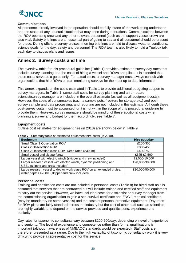
Annex 2. Survey costs and time The overview table for this procedural guideline (Table 1) provides estimated survey day rates that include survey planning and the costs of hiring a vessel and ROVs and pilots. It is intended that these costs serve as a guide only. For actual costs, a survey manager must always consult with organisations that hire ROVs or plan monitoring surveys for the most up to date information. This annex expands on the costs estimated in Table 1 to provide additional budgeting support to survey managers. In Table 1, some staff costs for survey planning and an on-board scientist/survey manager are included in the overall estimate (as well as all equipment costs). However, the costs of consumables (such a sample pots, freezers for storage etc.) and post-survey sample and data processing, and reporting are not included in this estimate. Although these post-survey costs must be accounted for it is not within the scope of this procedural guideline to provide them. However, survey managers should be mindful of these additional costs when planning a survey and budget for them accordingly, see Table 7. Equipment costs Outline cost estimates for equipment hire (in 2018) are shown below in Table 9. Table 7. Summary table of estimated equipment hire costs (in 2018).
Equipment Hire cost/day
Small Class 1 Observation ROV £250-350
Class 2 Observation ROV £350-450
Class 2 Observation class ROV- Deep rated (>300m) £400-750
Small vessel and skipper/crew £625-£2,500
Larger vessel with electric winch (skipper and crew included) £2,500-10,000
Larger research vessel with electric winch, dynamic positioning and USBL (skipper and crew included)
£20,000-30,000
Large research vessel to deploy work class ROV on an extended cruise, water depths >200m (skipper and crew included)
£30,000-50,000
Personnel costs Training and certification costs are not included in personnel costs (Table 8) for hired staff as it is assumed that services that are contracted out will include trained and certified staff and equipment to carry out the service. However, we have included costs for a scientist or survey manager from the commissioning organisation to gain a sea survival certificate and ENG 1 medical certificate (may be mandatory on some vessels) and the costs of personal protective equipment. Day rates for ROV pilots are fairly standard across the industry but the cost of other staff such as scientists are highly variable and depend on the service provided and qualifications, experience and seniority. Day rates for taxonomic consultants vary between £200-600/day, depending on level of experience and seniority. The level of experience and competence rather than formal qualifications is important (although awareness of NMBAQC standards would be expected). Staff costs are, therefore, presented as a range. Due to the high variability of taxonomic consultancy work it is very difficult to provide a representative cost for this service.

Marine Monitoring Platform Guidelines
21
Table 8. Summary table of estimated personnel costs to carry out survey and sample processing (in 2018).
Personnel Day rates or other costs
ROV pilot £350 (inshore) – 450 (offshore)
Scientist/survey manager/data analysts/reporting staff £225-700
Taxonomic consultants £200-600
Travel & Subsistence £50-200
Sea Survival Certificate (certificate and salary cost) Certificate 1-3 days £100-500, salary costs to attend course £225-2100
ENG 1 Medical Certificate £80
Personal Protective Equipment (PPE), foul weather gear, toe-capped boots, hard hat
£250-700 per/person
Data archiving Three costings scenarios were supplied by the MEDIN Data Archiving Centre DASSH12, based on a representative range of scenarios that they encounter (Table 9). Table 9. Data archiving costs for three scenarios that are commonly encountered by DASSH (in 2018).
Scenario Description Day allocation and cost
1 DASSH is core funded by Defra to archive data in MEDIN format, so there is no charge for data archival if it is provided in this format. It is estimated that MEDIN compliant data would require the timeline for archiving would depend on the current workload within DASSH.
2 days of archival time, £0
2 Small to medium sized datasets (<1,000 samples) with species abundances and locations (decimal degrees) that were supplied in an Excel spreadsheet but not in MEDIN format.
10 days @ £340/day (Total cost £3,400)
3 Provision of a multi-disciplinary, large dataset with species records provided as an Excel spreadsheet. Dates of samples and biotope locations are provided in a map in the report PDF. No data is presented in MEDIN format and extensive processing and Quality Assurance (QA) procedures are required.
20 days @ £320/day*. (Total cost £6,400)
*The reduced day cost is due to the proportional increase of time of staff with lower day rates (data officer and data manager time).
Cost variability Key factors that lead to cost variation between surveys, include:
• Complexity of operations, number of stations to be surveyed, distance from shore and depth as: o planning requirements will be greater due to the increased complexity, scale and risk
of all survey stages; o length of survey increases hire costs; o distance travelled by vessel will affect fuel consumption and length of hire; and o ROV pilots are paid more when working offshore as less comfortable for pilot, more
risk and more safety certificates required.
• Size and capability of ROV required as larger and more specialised ROVs and sampling tools are more expensive to hire and require more operators with higher skill/experience levels.
• Mobilisation and travel and subsistence rates of pilots and staff will be highly variable, depending on distance travelled and whether the pilots are working inshore and returning to hotels or housed on a larger vessel.
• Demand for ROV surveys from other sectors influencing hire rates.
• Sample processing costs for video and stills are highly variable depending on requirements, including:
12 http://www.dassh.ac.uk/
Marine Monitoring Platform Guidelines
22
o diversity in and between samples both in terms of the physical environment and the number of taxa;
o the level of detail to be derived from the imagery and additional characteristics to be recorded, e.g. evaluation of their quality of features, evidence of damage, presence of litter etc;
o level and type of breakdown of substrate composition required can be time consuming, especially for mixed sediments and variable seabed types;
o cost of developing a reference collection of georeferenced images of both biotopes, taxa and sediment classes; and
o quality control– how many samples are required to be re-analysed.
• Other types of sample and data processing, e.g. processing infaunal samples, radio carbon dating, etc.
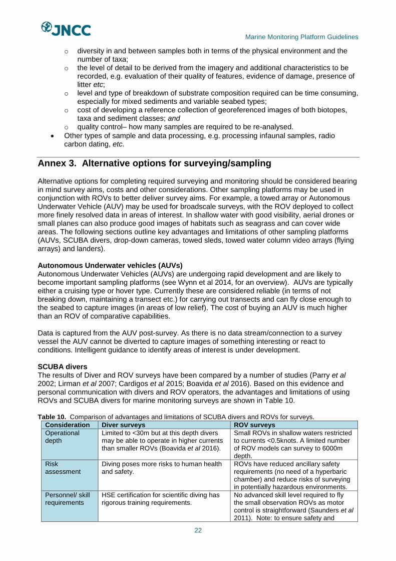
Annex 3. Alternative options for surveying/sampling Alternative options for completing required surveying and monitoring should be considered bearing in mind survey aims, costs and other considerations. Other sampling platforms may be used in conjunction with ROVs to better deliver survey aims. For example, a towed array or Autonomous Underwater Vehicle (AUV) may be used for broadscale surveys, with the ROV deployed to collect more finely resolved data in areas of interest. In shallow water with good visibility, aerial drones or small planes can also produce good images of habitats such as seagrass and can cover wide areas. The following sections outline key advantages and limitations of other sampling platforms (AUVs, SCUBA divers, drop-down cameras, towed sleds, towed water column video arrays (flying arrays) and landers). Autonomous Underwater vehicles (AUVs) Autonomous Underwater Vehicles (AUVs) are undergoing rapid development and are likely to become important sampling platforms (see Wynn et al 2014, for an overview). AUVs are typically either a cruising type or hover type. Currently these are considered reliable (in terms of not breaking down, maintaining a transect etc.) for carrying out transects and can fly close enough to the seabed to capture images (in areas of low relief). The cost of buying an AUV is much higher than an ROV of comparative capabilities. Data is captured from the AUV post-survey. As there is no data stream/connection to a survey vessel the AUV cannot be diverted to capture images of something interesting or react to conditions. Intelligent guidance to identify areas of interest is under development. SCUBA divers The results of Diver and ROV surveys have been compared by a number of studies (Parry et al 2002; Lirman et al 2007; Cardigos et al 2015; Boavida et al 2016). Based on this evidence and personal communication with divers and ROV operators, the advantages and limitations of using ROVs and SCUBA divers for marine monitoring surveys are shown in Table 10. Table 10. Comparison of advantages and limitations of SCUBA divers and ROVs for surveys.
Consideration Diver surveys ROV surveys
Operational depth
Limited to <30m but at this depth divers may be able to operate in higher currents than smaller ROVs (Boavida et al 2016).
Small ROVs in shallow waters restricted to currents <0.5knots. A limited number of ROV models can survey to 6000m depth.
Risk assessment
Diving poses more risks to human health and safety.
ROVs have reduced ancillary safety requirements (no need of a hyperbaric chamber) and reduce risks of surveying in potentially hazardous environments.
Personnel/ skill requirements
HSE certification for scientific diving has rigorous training requirements.
No advanced skill level required to fly the small observation ROVs as motor control is straightforward (Saunders et al 2011). Note: to ensure safety and

Marine Monitoring Platform Guidelines
23
quality of survey, experience and competency are desirable.
Personnel requirements/ costs
Diving requires a larger team (minimum 4 divers, with one acting as supervisor) and shore management/cover. Typical: 4 HSE scientific divers, 1 supervisor. (£300-£400 day rate)
ROV requires a single pilot with optional tether manager for simple observation surveys using a micro ROV in <30m depth (more complex operations with Class II and Class III ROVs do, of course, require more than one person).
Survey requirements-scale
Divers may cover more ground in a survey (may be faster and with no restriction from tether). In studies, small ROVs have been found to be slow moving compared to divers (Cardigos et al 2015).
ROVs can survey longer, ascend and descend repeatedly (unlike divers), and survey multiple stations in one survey day (Boavida, et al 2016). ROVs proved less time consuming than diver operations and were useful for sampling a large area or a number of sites (Andaloro et al 2013).
Sampling aims/ requirements
Divers have increased spatial awareness, visual acuity and can zoom and focus cameras (Boavida et al 2016; Parry 2002). Divers are versatile and can adapt to situations (e.g. collect samples of interest) and can be more efficient and selective when collecting samples (Boavida et al 2016). Divers can communicate with surface support using full face masks and may be able to live-stream images to surface but this is not routine. Divers may be better at identifying small species and cryptic species or those hidden in crevices (Consoli et al 2009).
ROVs can collect continuous footage that is live-streamed to the surface to allow survey plans to adapt and change according to situation. Reported performance of ROV manipulator arm collection varies between species groups (and potentially may depend on operator skill). Reported performance of ROV manipulator arm collection varies between species groups (and potentially operator). For example, Hughes et al (2010) found that echinoids with tests could be successfully collected, whereas Kazanidis et al (2016), found that a small proportion of species living in association with sponges colonising coral rubble, such as polychaetes, were damaged by the ROV arm.
Sampling aims/ requirements
Different scope for carrying equipment than ROV, divers can carry a range of equipment including quadrats.
Small Class 1 ROVs have low power and can’t carry many accessories. A larger deeper rated ROV could be used. Optional accessories include multibeam echosounder.
Survey quality Quality of survey, based on comparison or results, is similar between both methods with some minor differences (Parry et al 2002; Boavida et al 2016).
Towed drop-down cameras and towed benthic sleds Other alternatives include drop cameras and towed benthic camera sleds (that are in contact with the seabed). These are generally cheaper, quicker, require less maintenance and are easier to deploy than ROVs. They can be towed to follow a line to conduct transects but there is little control over position and this lack of manoeuvrability is a key disadvantage when compared to ROVs. For transects, the advantage of a towed benthic sled is that the camera is always the same distance above the seabed so that the field of view is fixed, which facilitates the collection of imagery for quantitative data analysis. The sleds and drop-down camera can be fitted with laser scaling and other ancillary equipment such as CTD sensors. Towed benthic sleds and drop-down cameras are typically more rugged than ROVs. As these are not self-propelled powered there are no thrusters to become tangled with fishing gear or other debris. Sleds and towed arrays may be used at greater speeds than ROVs allowing greater spatial coverage. As towed gear can be pulled by steel cables on which greater pulling force can be exerted they should be considered where obstacles and fishing gear may be a risk.

Marine Monitoring Platform Guidelines
24
Towed benthic sleds are not suitable for use in rocky areas or over areas with overhangs and canyons, but will be fine in areas of mobile sediment with some stones. Towed systems or AUVs are a good option for initial exploration of broadscale areas to identify areas of interest with ROV surveys commissioned to do higher resolution survey work thereafter.
Marine Monitoring Platform Guidelines No. 1
Remotely Operated Vehicles for use in marine benthic monitoring. JNCC, Peterborough
ISSN 2517-7605