remotely operated vehiclethis remotely operated vehicle operations manual is designed to provide...
TRANSCRIPT
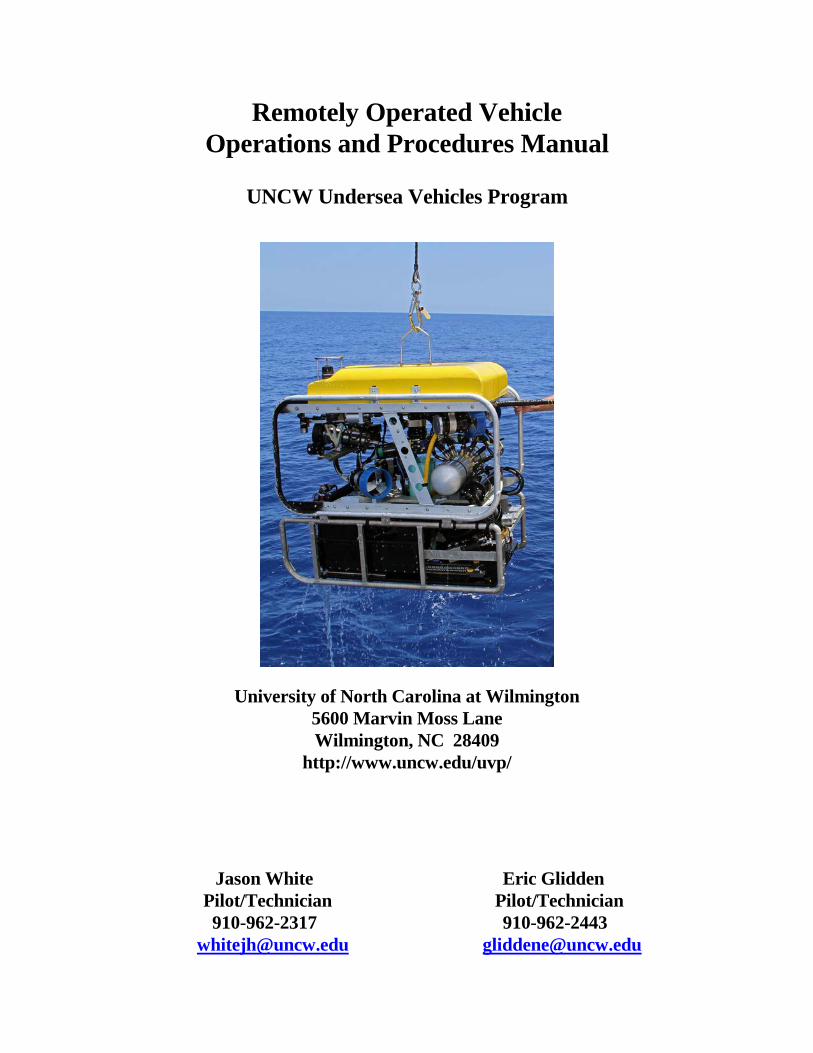
Remotely Operated Vehicle Operations and Procedures Manual
UNCW Undersea Vehicles Program
University of North Carolina at Wilmington 5600 Marvin Moss Lane Wilmington, NC 28409
http://www.uncw.edu/uvp/
Jason White Eric Glidden Pilot/Technician Pilot/Technician 910-962-2317 910-962-2443 [email protected] [email protected]
2
TABLE OF CONTENTS SECTION PAGE 1.0 GENERAL INFORMATION ........................................................................................................ 4 1.1 Introduction ............................................................................................................................ 4 1.1.1 Mohawk 18 .................................................................................................................. 4 1.1.2 Super Phantom S2 ....................................................................................................... 4 1.1.3 Phantom 300 ................................................................................................................ 4 1.2 Scope ...................................................................................................................................... 4 1.3 Exceptions .............................................................................................................................. 4 2.0 ROV DIVING STANDARDS ......................................................................................................... 5 2.1 Depth ...................................................................................................................................... 5 2.2 Bottom Type .......................................................................................................................... 5 2.3 Penetrations ............................................................................................................................ 5 2.4 Sea Conditions ....................................................................................................................... 5 2.4.1 Seastate ...................................................................................................................... 5 2.4.2 Currents ..................................................................................................................... 5 2.4.3 Visibility .................................................................................................................... 5 2.5 Personnel Requirements ........................................................................................................ 5 2.5.1 Manning Levels ......................................................................................................... 5 2.5.2 Responsibilities ......................................................................................................... 6 A. Operator ........................................................................................................ 6 B. Tender ........................................................................................................... 6 C. Bridge Personnel ........................................................................................... 6 D. Scientific Observer ....................................................................................... 6 2.5.3 Scientist Training and Qualifications ....................................................................... 7 2.6 Equipment .............................................................................................................................. 7 2.6.1 Remotely Operated Vehicle ...................................................................................... 7 2.6.2 Integrated Navigation System ................................................................................... 8 2.6.3 Video Recording ....................................................................................................... 8 2.6.4 Scientist Supplied Equipment ................................................................................... 9 2.6.5 Equipment Shipment ................................................................................................. 9 2.7 Record Keeping Requirements .............................................................................................. 9 2.7.1 Mission Dive Folder .................................................................................................. 9 A. ROV Dive Logs .......................................................................................... 10 B. Pre-mission Loadlist ................................................................................... 10 C. Pre- and Post-dive Checklist ...................................................................... 10 D. Trouble Report ............................................................................................ 10 2.7.2 Video Tape Procedures ........................................................................................... 10 2.7.3 Maintenance ............................................................................................................ 10 3.0 OPERATIONAL PROCEDURES .............................................................................................. 11 3.1 General Policy ...................................................................................................................... 11 3.2 Communications .................................................................................................................. 11 3.3 Deployment and Recovery .................................................................................................. 11
3
3.4 Pre- and Post-dive Procedures ............................................................................................. 11 3.4.1 Pre-dive Procedures ................................................................................................ 11 3.4.2 Post-dive Procedures ............................................................................................... 12 3.5 Emergency Operations ......................................................................................................... 12 3.5.1 General Policy ......................................................................................................... 12 3.5.2 Primary Contacts ...................................................................................................... 12 3.5.3 Entanglement ........................................................................................................... 13 3.5.4 Tether in Vessel's Wheel ......................................................................................... 13 3.5.5 Tether Severed Completely ..................................................................................... 13 3.6 Hours of Operation .............................................................................................................. 14 3.7 Operating Modes ................................................................................................................. 14 3.7.1 Vessel at Anchor ..................................................................................................... 14 3.7.2 Live-Boat Operations .............................................................................................. 15 3.7.3 Night Operations ..................................................................................................... 15 3.8 Maintenance ......................................................................................................................... 16 3.8.1 Routine .................................................................................................................... 16 3.8.2 Emergency ............................................................................................................... 16 APPENDICES 1. ROV Dive Log ........................................................................................................................... 17-18 2. ROV Super Phantom Load Lists ............................................................................................... 19-20 3. Pre-dive Checklist ............................................................................................................................ 25 4. Post-dive Checklist ........................................................................................................................... 27 5. Trouble Report Form ....................................................................................................................... 28 6. ROV Piece Weight List .................................................................................................................... 29 7. Mission Coordinator’s Daily Log .................................................................................................... 30 8. ROV Dive Summary Log ................................................................................................................ 32 9. Tether Management ......................................................................................................................... 33
4
1.0 GENERAL INFORMATION
1.1 Introduction
This remotely operated vehicle operations manual is designed to provide guidelines for the use of UNCW's Mohawk, Super Phantom S2, and Phantom 300 remotely operated vehicles (ROV). Following these guidelines will ensure the safe performance of ROV research operations for the equipment and personnel involved. It is the responsibility of all participating personnel to comply with the policies and safe operating practices set forth in this manual. 1.1.1 Mohawk – The Mohawk is a sophisticated state of the art fiber optics ROV. The ROV is equipped with a HD color video camera, 10 megapixel digital stills camera and strobe, LED lights, altimeter, 50 mW green lasers for scaling, navigation instruments, and powered tilt platform. The current setup of the Mohawk allows it to be operated with just 2 staff members.
1.1.2 Super Phantom S2 - The Super Phantom S2 is a powerful and maneuverable ROV that can be deployed from a wide variety of support platforms. This light weight system can be deployed by two operators and is designed as an underwater platform which provides support services including color video, digital still camera and strobe, parallel lasers for scaling, navigation instruments, lights and a powered tilt platform. A wide array of specialty tools and sampling devices are available. (See Appendix 9)
1.1.3 Phantom 300 - The Phantom 300 ROV is a small, lightweight, highly portable system used for video documentation only from a variety of support platforms. It has extremely limited payload capabilities and no spare wires for power to external instrumentation. The Phantom 300 has a Sony zoom color camera on a tilt platform and fixed lights. The cable is 350 feet long allowing access to depths of 300 feet seawater.
1.2 Scope This manual is to be used for mission planning and implementation in conjunction with direct consultation with the UNCW office. Primary contacts regarding operations:
Jason White
Operations Director 5600 Marvin Moss Lane Wilmington, N.C. 28409 Phone (910) 962-2317 Fax (910) 962-2410 Cell (252) 717-3099 [email protected]
5
1.3 Exceptions
Deviation from these guidelines may be approved by the UNCW ROV Coordinator or designee upon ascertaining that such procedures are safe and essential to program operations. The circumstance leading to the situation, the deviation made, and the action taken shall be fully documented in the ROV mission diving folder.
2.0 ROV DIVING STANDARDS
2.1 Depth The Mohawks tether is 360 meters long and therefore that vehicle’s maximum depth is 300 meters. The Super Phantom S2 tether of 320 meters limits the maximum depth capability to approximately 290 meters. The Phantom 300 tether is 106 meters long so it can access depths up to 90 meters. Current, support vessel anchoring requirements and natural obstacles will decrease the depth range of the vehicle. 2.2 Bottom Type Bottom type directly affects the operational capability of the ROV. A flat, sandy bottom poses no threat to the vehicle, while a shipwreck, rocky outcroppings, and/or coral protrusions can trap the vehicle, or more likely, the tether. For this reason, the UNCW staff operator retains the final decisions as to the vehicle's safety and continuation of operations. 2.3 Penetrations Penetrations into large, natural enclosures will be considered only after a thorough external visual inspection. As a rule, penetrations into wrecks or areas that limit maneuverability shall not be performed. No penetrations will be permitted during live-boat operations. 2.4 Sea Conditions
2.4.1 Sea state - The ROV can operate in seas up to an 8-foot swell or 6-foot chop during day time operations and up to 3 feet during night time operations. Sea state is most critical during deployment and recovery when the ROV is in close proximity to the support vessel. When the ROV and support vessel collide in rough seas, the ROV will always be the loser. Any sea that endangers the tender, such as waves coming over the side causing poor footing or causing the launch vessel to become unstable, will preclude ROV operations. Any seas that hamper vessel maneuverability during live-boating will also preclude ROV operations. 2.4.2 Currents - Current greatly reduces ROV maneuverability and affects the tether, which may limit the depth that the ROV can reach. ROV operations can be conducted with a fair amount of certainty in 1-knot currents. Without special deployment techniques, which will be discussed later, the ROV can barely hold its position on the bottom in a 2-knot current.
6
2.4.3 Visibility - In general, the ROV can operate in visibility of 2' or greater. In areas where obstacles are expected, this distance shall be increased at the discretion of the ROV Coordinator.
2.5 Personnel Requirements 2.5.1 Manning Levels - Deployment and operation of the ROV requires a minimum of two individuals, an operator, and a tender. These positions are normally held by qualified, trained staff personnel, however, scientists and/or mission participants can fill the positions after adequate training. A member of the scientific team will be designated as scientific observer. A MINIMUM OF ONE STAFF ROV TECHNICIAN MUST BE PRESENT DURING ROV OPERATIONS. 2.5.2 Responsibilities
A. Operator - The ROV operator is responsible for:
1. The safety of the ROV and peripheral equipment. 2. Coordination of the ROV dive with P.I. and vessel personnel. 3. Coordination of overall vessel, tether, and vehicle speed & movement with Ship's
Captain and ROV tender during all operations. This includes setting up communications between the bridge, deck (tender), and ROV operator.
4. Termination of ROV operations when conditions endanger the ROV or personnel.
5. Set up of the ROV and peripheral equipment, wiring, and power supply. 6. Continually monitor the orientation and amount of ROV tether deployed to
prevent snagging or fouling. 7. Continually monitor the depth of the down-weight to prevent snagging or
fouling. 8. Recovery and deployment of the vehicle and LinkQuest hydrophone. 9. Vehicle and peripheral equipment maintenance. 10. Updating & recording OSD Title Header on DVDs and video recordings. 11. Completion of mission dive log and all associated forms.
B. Tender - The ROV tender is responsible for:
1. Confirming oil compensators are open and transponder is hooked up. 2. Request permission and supervise deployment of hydrophone pole and ROV. 3. Proper management of ROV tether and down-weight. 4. Keeping the operator informed of length of tether deployed and location in
relation to the vessel. 5. Coordination of vessel movements in relation to tether’s proximity to vessel's
propellers, hull, and the hydrophone pole. 6. Monitoring hydrophone pole movement & vibration during the dive. 7. Ensuring that the tether is safe from shipboard hazards such as snagging, fouling,
cuts, abrasions, heat, etc and from buoys and fishing gear. 8. Securing hydrophone pole, ROV, and tether on deck after recovery of the ROV.
7
C. Bridge Personnel - Bridge personnel are responsible for:
1. Monitoring navigational equipment and mooring line to ensure stable vessel
positioning. 2. Maintaining vessel position so that in the event of loss of power the vessel would
not drift over the ROV. 3. Communication of status of vessel position, heading, and speed over ground to
ROV operator and tender. 4. Maintaining the vessel's position with the ROV during live-boat operations.
D. Scientific Observer - The scientific observer is responsible for:
1. Coordination of ROV tasks with the operator before operations commence. 2. Voice narration of video recordings made during the dive. 3. Completion of all reports required by UNCW and applicable portions of the
ROV dive log designated by the operator. 4. Helping the operator with the operation of peripheral equipment when necessary. 5. Operation of video recording equipment and labeling of the video media.
2.5.3 Scientist Training and Qualifications
A. Scientist may serve as ROV tender after a thorough training session. During the training session, a staff ROV technician will cover the information contained in the appropriate manuals for the responsibilities of the tender.
B. At least one staff ROV technician will always be present throughout operations to operate the ROV.
2.6 Equipment
All of the topside electronic equipment shall be kept and operated from an enclosed area safe from weather, salt spray, extreme temperature, and humidity changes. The equipment shall be securely mounted on a stable, permanent bench or table prior to the vessel getting underway.
2.6.1 Remotely Operated Vehicle
A. The minimum equipment necessary for an ROV mission consists of the following:
1. Remotely operated vehicle 2. ROV control console or pilot station and power cords 3. Cable/Tether 4. Isolation transformer 5. VHF radio transceivers 6. Assorted weights and floats for vehicle trim and tether management
8
7. Spares kit 8. Tool kit 9. ROV Operations and Procedures Manual 10. ROV Technical Manuals Binder 11. Mission dive folder 12. Video Console 13. Integrated Navigation System
B. A list of optional equipment including tools, sampling devices, and their use is
contained in Appendix 9.
2.6.2 Integrated Navigation System (INS) - The ROV uses an integrated navigation system consisting of Hypack 2017 software on a Windows 7 64 bit 3.4 GHz computer, LinkQuest TrackLink 1500HA Acoustic Tracking System with an LinkQuest 1505b transponder, and Trimble SP461 dual antenna DGPS/Compass. This system provides real time tracking of the ROV and ship to the ROV operator and the support vessel’s bridge for navigation. ROV personnel install a Trimble dual DGPS antenna and an TrackLink hydrophone on the vessel and survey their positions with respect to a reference point at the center of the vessel. DGPS antenna and hydrophone offsets, as well as ship dimensions, are entered into the Hypack 2017. The TrackLink interrogates the LinkQuest 1505b transponder on the ROV. Using the TrackLink hydrophone, TrackLink determines slant range, bearing, and depth. The real-time Hypack navigation screen accurately displays the ship (to scale) with proper position and heading, and the position and heading of the ROV. Ship and ROV positions are logged and processed for each dive and provided to the scientist in an Excel file. Geo-referenced .tif files obtained with multibeam or side scan sonar can be entered into Hypack as background files to display target sites and features of interest to aid in ROV and support vessel navigation. The LinkQuest acoustic tracking system can track up to 16 targets at one time.
A. The TrackLink system is required during live-boating operations or when operating in
low visibility or high risk areas where entanglement is possible. B. Its use is recommended for all dives except those performed shallower than 45 fsw. C. Acoustic beacons will only be deployed when their recovery is reasonably ensured.
The operator will determine where and how the beacon should be deployed, and the risk involved.
D. Should tracking of the ROV or beacon be required, the following equipment shall be
used:
1. INS console with DGPS Trimble Receiver and computer 2. LinkQuest hydrophone with mounting bracket 3. Hydrophone cable 4. Hydrophone mounting pole and associated hardware
9
5. Transponders 6. Transponder power adapter/charger
2.6.3 Video Recording - ROV missions will require video documentation of in water operations.
The video console contains all essential equipment necessary for documentation of the dive. The video console includes:
1. 2 Color monitors (19" Diagonal) 2. Toshiba DVD recorder (one hour record time) 3. 3 Digital recorders capable of recording in several formats 4. Microphone for voice annotation onto the recording media 5. Sufficient number of DVD’s and hard drive space for daily operations 6. Additional assortment of video patch cords and adapters.
2.6.4 Scientist Supplied Equipment
A. Plans to attach additional scientific instruments to the ROV must be submitted to the
ROV coordinator a minimum of one week prior to shipment or transport of the ROV equipment from the UNCW facility at Wilmington, N.C.
B. The ROV coordinator shall determine feasibility of attachment points and necessary
electrical wiring. C. Attachment of scientific equipment is limited to the ROV crash frame, tilt unit,
manipulator, or designated mounting structures. D. Any equipment that impedes movement of the thrust motors or tether management will
not be considered. Any equipment that impedes the movement of the tilt platform will be considered only at the discretion of the ROV operator.
Note: See Appendix 8 for a schematic drawing of the ROV positioned in the crash frame.
2.6.5 Equipment Shipment
A. Missions requiring shipment by an independent carrier must be carefully planned and organized. Completion of load lists (see Appendix 2) will ensure that every possible piece of equipment required to complete the mission is included.
B. After loading the boxes, a list of container numbers, container sizes, and weights must
be calculated. A copy of the list shall be placed in each box. One copy will be given to the carrier. The original shall go in the mission dive folder along with the U.S. Customs Certificates of Registration (when shipped to a foreign country), Shippers Invoice, Bill of Laden, and all receipts.
10
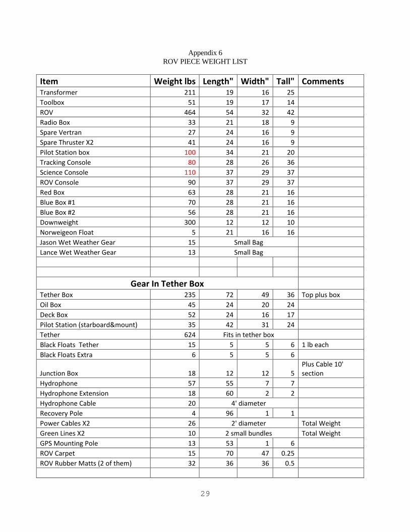
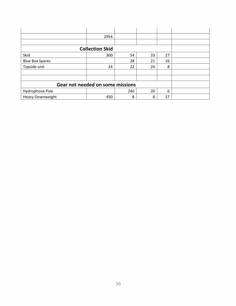
Note: A list of container measurements and the weight of each piece of equipment can be found in the ROV Piece Weight List (Appendix 6).
2.7 Record Keeping and Documentation 2.7.1 Mission Dive Folder - A permanent record shall be kept of all ROV missions including
cruise plans, communications, equipment load lists, dive log sheets, dive plans, operations schedules, and other pertinent information. A. ROV Dive Logs (Appendix 1) - A record of each ROV dive will be kept in the mission
dive folder. All of the information spaces of the log must be filled in. Copies of the dive logs will be included with all other mission documentation on external hard drive.
B. Pre-Mission Load list (Appendix 2) - Proposal requirements and the mission cruise
plan will be checked prior to loading in order to ascertain which load lists will be pertinent for the successful completion of the mission. The required load lists will then be completed for each mission prior to departure from UNCW. This will ensure that all required items for the mission are accounted for and loaded.
C. Pre- and Post-Dive Checklist (Appendix 3 and 4)
1. The pre-dive checklist shall be completed to ensure vehicle readiness, safety, and correct electrical hook-up.
2. The post dive checklist is performed after each dive as a standard maintenance function to extend vehicle longevity.
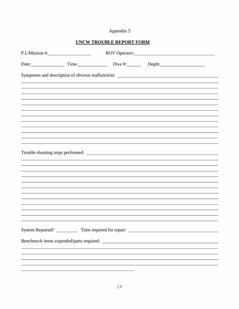
D. Trouble Report (Appendix 5) - All ROV or LinkQuest failures and damage will be
documented with the Trouble Report Form. The nature of the problem and all trouble shooting efforts shall be recorded for future reference.
2.7.2 Video Recording Procedures
A. Generally, DVD and digital recording begins when the ROV nears the bottom. Recording the transit through the water column is available upon request.
B. The OSD provides a title page with information such as mission number, P.I. name,
support vessel name, general location, ROV Dive number, DVD disk number, and any other pertinent information that the scientist requires. This information is recorded as a header at the beginning of each DVD disk. The OSD also provides data overlay on the video including time, date, ROV heading ribbon, ROV numeric heading in degrees, ROV depth in meters, and ROV umbilical cable turns counter for the pilot.
C. Digital media and original DVDs go to the PI/Chief Scientist. Copies are not
maintained at UNCW; therefore, it is the responsibility of the PI/Chief Scientist to maintain the video media after the mission.
11
2.7.3 Maintenance
A. All routine maintenance of the ROV system, LinkQuest Tracking system, and
accessories shall be recorded in the appropriate UNCW equipment maintenance folder.
3.0 OPERATIONAL PROCEDURES
3.1 General Policy Every effort shall be made to complete the scientific task proposed by the Principal Investigator without placing the vehicle in jeopardy. In order to do this, all scientific requirements shall be thoroughly discussed and planned with the Principal Investigator to maximize efficiency and the successful completion of the mission objectives. Ultimate responsibility for vehicle and personnel safety rests with the ROV supervisor/operator. Therefore, it is the supervisor/operator's responsibility and duty to refuse to commit the ROV if conditions are unsafe, unfavorable, or they would be violating the conditions of their training or the regulations in this manual. 3.2 Communications Communications between the operator and the tender shall be maintained at all times. Since live-boat operations greatly enhance the possibility of the tether being cut or entangled in the vessel's propeller(s), communications with the vessel's bridge shall be maintained at all times during live boat operations. The ROV operator and tender may jointly decide in directional information to be given to the vessel's bridge, but the information is to be conveyed by the ROV tender only. Any movement of the vessel while at anchor must be communicated to and coordinated with the ROV operator and tender. 3.3 Deployment and Recovery A "permission to launch the ROV" must be received from the vessel's bridge prior to deployment of the ROV. The ROV shall be supported by the crash frame or the ROV lifting eye and not the tether during deployment and recovery. Be aware of any equipment, weights, or floatation attached to the crash frame that may snag on the side of the vessel during deployment and recovery. The tender shall ensure that sufficient tether is available for the ROV to reach the water during deployment. No fishing gear may be in the water during ROV operations. 3.4 Pre- and Post-Dive Procedures 3.4.1 Pre-Dive Procedures
A. The equipment will be set up in accordance with the pre-dive checklist (Appendix 3).
A quick test of all ROV functions will be performed prior to each dive.

12
B. Pre-Dive Briefing - A pre-dive briefing shall be conducted each day before the vehicle
enters the water. The supervisor/operator, tender, scientists involved, and any vessel crew involved in maneuvering the vessel shall be in attendance. Topics shall include objective(s) of the dive, specific task assignments, dive profile information, vessel movements, tether management, anticipated conditions and hazards, and safety precautions.
3.4.2 Post-Dive Procedures - The post-dive checklist shall be completed upon completion of
each dive. 3.5 Emergency Operations
3.5.1 General Policy A. In the event of an equipment failure during dive operations, the ROV operator shall
assess the situation and decide if dive operations should be terminated. B. Any problems with the vehicle or tether will automatically necessitate the termination
of the ROV dive until the problem can be isolated and resolved. This will preclude further damage to the vehicle, ensure operator safety, and enhance the continuation of ROV operations. After a failure has been isolated and determined to be non-detrimental to other components in the system, ROV dive operations may be resumed.
C. Failure of peripheral equipment, (i.e., LinkQuest, video system, manipulator, etc.) will
not necessarily preclude operations unless the dive is specifically based on that equipment.
3.5.2 Primary Contacts
A. Super Phantom Deep Ocean Engineering, Inc. 1431 Doolittle Drive San Leandro, CA 94577 (510) 562-9300 (510) 430-8249 (Fax) Darrell Martin ([email protected]) Joe Andrade ([email protected]) – electronics B. Mohawk Sub-Atlantic-FORUM Energy Technologies 10344 Sam Houston Park Drive Suite 300 Houston, Tx 77064 561-402-0568 (US 24 hour number) Alvaro Pereyda: or [email protected]
13
[email protected] (24 hour support UK) B. TrackLink LinkQuest, Inc. 6749 Top Gun St. #100 San Diego, CA 92121 (858) 623-9900 Dr. Ning Xiao <[email protected]>
3.5.3 Entanglement - Should the vehicle become hopelessly trapped, UNCW shall be notified at first opportunity. If the vessel must leave the area, the following steps shall be taken:
1. Do not try to recover vehicle by putting excessive tension on tether! 2. Obtain best navigational fix available from the bridge, and record the last
position with the LinkQuest Navigation system. 3. Secure all power to console and vehicle. 4. Disconnect tether from junction box. 5. Seal tether end with several plastic bags to prevent water from entering tether. 6. Secure a fresh transponder on the tether, about 100' from the surface end if
possible. 7. Secure surface end of tether to largest buoy available. 8. Let out all tether and buoy gradually, do not toss all overboard at once. 9. Mark site with additional buoy and mooring. 10. Take navigational fixes on both buoys. 11. Return to port.
3.5.4 Tether in Vessel's Propeller(s)
1. Secure vessel's propeller(s) as soon as possible. 2. If vehicle is still operable, drive to surface and recover. 3. Secure power to ROV. 4. If not operable, try to locate tether or buoy between propeller(s) and vehicle and
recover vehicle manually. 5. If dive equipment is available or the propeller(s) can be reached by breath
holding, an attempt should be made to pass a line around the vehicle end of the tether and recover the vehicle manually. Note: Every effort to recover the vehicle shall be exhausted. Vehicle recovery is first priority.
6. If available, divers should attempt to clear tether out of vessel's propeller(s). 7. If divers cannot clear propeller(s), and vehicle has not been recovered, obtain best
navigational fix from bridge and attach large buoy to vehicle end of tether with enough rope that the buoy will float on the surface.
8. Attach fresh transponder to tether. 9. Sever tether between propeller(s) and buoy as close to propeller(s) as possible. 10. Try to recover ROV. 11. Cut tether out of propeller(s).
14
12. If unable to recover ROV, return to port, discuss situation and options with UNCW office.
3.5.5 Tether Severed Completely
1. Secure ROV console power. 2. Get bridge to record vessel position as soon as possible. 3. Locate transponder on vehicle with LinkQuest and record las position. 4. If surface buoy was attached to tether, locate buoy. 5. Recover buoy, tether and vehicle if possible. 6. Contact UNCW office and relay situation.
3.6 Hours of Operation
ROV operations require the full concentration of the operator at all times. In order to maintain ROV operations at peak performance, operators shall perform no more than a maximum of five continuous hours of dive time. Dive operations shall then be terminated or operators will be rotated. After a one hour break, the original operator can return for another five hour period of vehicle operations. ROV operations can be performed during the day or night, but each operator shall be given the opportunity to acquire at least eight hours of continuous sleep per day. Normal work hours for personnel engaged in ROV operations should not exceed twelve hours during any twenty-four hour period.
3.7 Operating Modes
The following information will provide some guidelines for different modes of operation. Operating mode and bottom type will require different techniques of tether management. Several techniques of tether management are discussed in Appendix 10.
3.7.1 Vessel at Anchor
A. This mode of operation greatly reduces two major operational concerns; vessel motion
in relation to the vehicle and entanglement of the tether in the vessel's propeller. With the vessel using one anchor, all but major vessel swings can be handled through tether management. Therefore, whenever possible, support vessels shall be anchored prior to performing ROV operations.
B. When operating the ROV from an anchored vessel, the following precautions shall be
taken: 1. Tender and bridge shall alert operator of major current or wind shifts that could
affect vessel mooring. 2. Tender shall inform operator when there is a possibility of the tether becoming
entangled with the anchor line.
15
3. The ROV shall not be deployed until the bridge informs the ROV personnel that the vessel is anchored and settled in its mooring.
4. The bridge shall notify the ROV operator if the vessel begins to drag anchor or loses its mooring.
3.7.2 Live-Boat Operations
A. This is a common mode of operation that can make ROV operations difficult and complex. Smaller, more maneuverable vessels or vessels with dynamic positioning (DP) are better for this type of operation, larger vessels tend to pull the ROV off station.
B. Extra precaution must be taken during ROV operations on shipwrecks or large
obstacles to avoid dragging the ROV into an entanglement situation. C. When operating the ROV from an unanchored vessel, the following stipulations and
precautions apply:
1. Bridge shall maintain communication with ROV personnel throughout the ROV dive.
2. When not using the downweight deployment technique, a surface buoy should be secured to the tether and maintained at a distance far enough from the side of the vessel for the bridge to monitor.
3. Requests for maneuvers by the vessel will be issued by the ROV tender only. The instructions given should always tend the tether away from the vessel's propellers.
4. The support vessel shall not exceed speeds of 2 kts. 5. Penetrations shall not be performed during live boat operations.
3.7.3 Night Operations
A. Night operations greatly reduce visibility above and in the water. Visibility is reduced
to 3-4 feet in water regardless of water clarity. The low-light (SIT) camera becomes useless due to the "no light" situation, and sees only what the lights illuminate (same as color camera).
B. When operating the ROV at night, the following stipulations and precautions apply:
1. No penetrations shall be attempted. 2. A surface buoy with a light source shall be attached to the tether. 3. To ensure safe operations, deck lights will sufficiently illuminate the deck as well
as the launch and recovery site.
16
4. The operator must focus greater concentration on preventing bottom entanglement.
3.8 Maintenance 3.8.1 Routine Maintenance – Routine or scheduled maintenance shall be performed in
accordance with the UNCW equipment maintenance plan. The specific tasks and maintenance schedules contained in the maintenance plan are outlined from excerpts of the maintenance sections contained in the technical manuals for the equipment.
3.8.2 Unscheduled Maintenance - Emergency on site maintenance shall be performed as soon as
possible in accordance with the trouble shooting sections of the technical manuals. Prompt servicing is necessary to preclude further damage to other sensitive electrical components that comprise these systems.
Note: The ROV shall not be permitted to dive with a known mechanical impairment or
conditions which is likely to adversely affect the safety or continuing operation of the ROV or its operators.

17
Appendix 1
ROV Dive
# Operator ROV
System Principal
Investigator Institution Date Depth
(meters)
BT
(minutes)
Digital Video
# DVD # Place Platform Pu

18
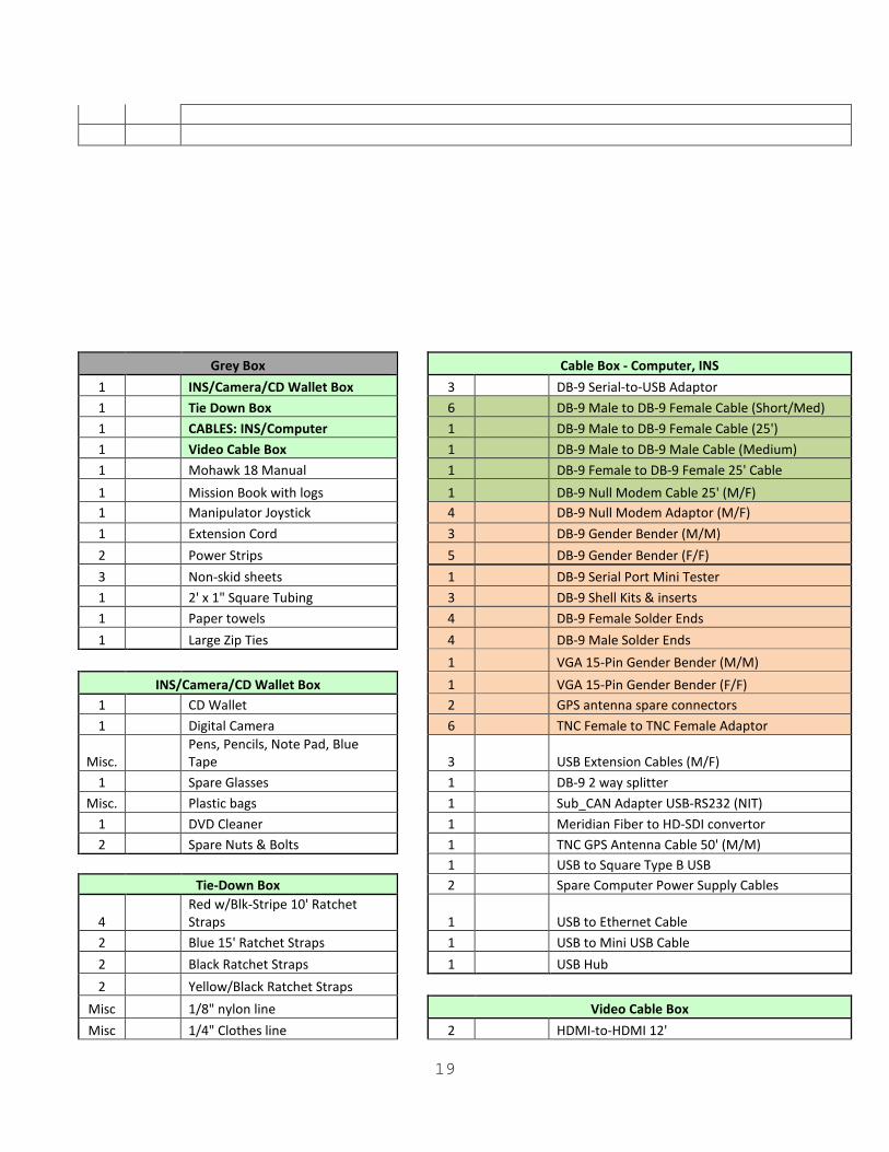
Appendix 2 1 Mohawk 18 ROV & Tool Skid
Hydrophone Gear
1 Tether Box
1 Hydrophone Pole 1 Isolation Xformer 440
1 100' Hydrophone Cable
3 ROV Consoles & Pilot Station
1 Hydrophone Transducer 1 Laptop (Macbook Pro)
1 Pole Extension & Hardware
1 Tool box 1 Charger Box
Bridge Monitor Case 1 Down Weight
1 19" Monitor with power cord
1 Recovery Pole
1 100' VGA Extension Cable 1 GPS Antenna Pole
1 6' VGA Cable
1 VHF Radio Antenna
1 9' VGA Extension Cable 1 Adjustable Padded Chair
1 Pilot Station Monitor Case
Tool Box 2 Spare Thrusters
1 Fluke Meter
1 Spare Vertran
1 Fluke Leads 2 Deck Gear
2 25' Tape Measure + 100' Tape Measure
1 Norwegian Buoy
3 Electrical Tape 1 Rug
1 Adjustable Pin Spanner Wrench
1 Rubber Mat for Down Weight
1 Strobe Wrench Misc. Truck Paperwork/Insurance
2 Flashlights
Misc. UVP T-shirts
Misc Cable Ties (4", 8", 14")
1 Hammer & Half-Round File
2 Hex Key Sets
3 Razor Blades
1 Hacksaw Blade
Pilot Station
1 Parker O-Lube 1 Hand Control Unit
1 Aqua Shield (Blue Goo)
1 Back-up Hand Control Unit
1 Q-Tips and Pipe Cleaners Bag 1 Video Camera Control
1 Tracking Pole Wrenches
1 Starboard Base
1 Steel Wool/Green Pads/Sandpaper Bag 1 Monitor Tree
2 Large and Small Wrench Set (Metric)
4 Monitors
1 Mini Screw Driver Set 1 Quad Controller
1 Rubber Pads Bag
Misc Hardware
1 Velcro Bag Misc Cables
1 Socket extension + 13mm socket
Misc Power Strip
1 Torque Wrench
1 Prop removal tool
1 Standard Wrenches and Hex Keys
19
Grey Box
Cable Box - Computer, INS
1 INS/Camera/CD Wallet Box
3 DB-9 Serial-to-USB Adaptor 1 Tie Down Box
6 DB-9 Male to DB-9 Female Cable (Short/Med)
1 CABLES: INS/Computer
1 DB-9 Male to DB-9 Female Cable (25') 1 Video Cable Box
1 DB-9 Male to DB-9 Male Cable (Medium)
1 Mohawk 18 Manual
1 DB-9 Female to DB-9 Female 25' Cable 1 Mission Book with logs
1 DB-9 Null Modem Cable 25' (M/F)
1 Manipulator Joystick 4 DB-9 Null Modem Adaptor (M/F) 1 Extension Cord
3 DB-9 Gender Bender (M/M)
2 Power Strips
5 DB-9 Gender Bender (F/F) 3 Non-skid sheets
1 DB-9 Serial Port Mini Tester
1 2' x 1" Square Tubing
3 DB-9 Shell Kits & inserts 1 Paper towels
4 DB-9 Female Solder Ends
1 Large Zip Ties
4 DB-9 Male Solder Ends
1 VGA 15-Pin Gender Bender (M/M)
INS/Camera/CD Wallet Box
1 VGA 15-Pin Gender Bender (F/F) 1 CD Wallet
2 GPS antenna spare connectors
1 Digital Camera
6 TNC Female to TNC Female Adaptor
Misc. Pens, Pencils, Note Pad, Blue Tape
3 USB Extension Cables (M/F)
1 Spare Glasses
1 DB-9 2 way splitter Misc. Plastic bags
1 Sub_CAN Adapter USB-RS232 (NIT)
1 DVD Cleaner
1 Meridian Fiber to HD-SDI convertor 2 Spare Nuts & Bolts
1 TNC GPS Antenna Cable 50' (M/M)
1 USB to Square Type B USB
Tie-Down Box
2 Spare Computer Power Supply Cables
4 Red w/Blk-Stripe 10' Ratchet Straps
1 USB to Ethernet Cable
2 Blue 15' Ratchet Straps
1 USB to Mini USB Cable 2 Black Ratchet Straps
1 USB Hub
2 Yellow/Black Ratchet Straps Misc 1/8" nylon line
Video Cable Box Misc 1/4" Clothes line
2 HDMI-to-HDMI 12'
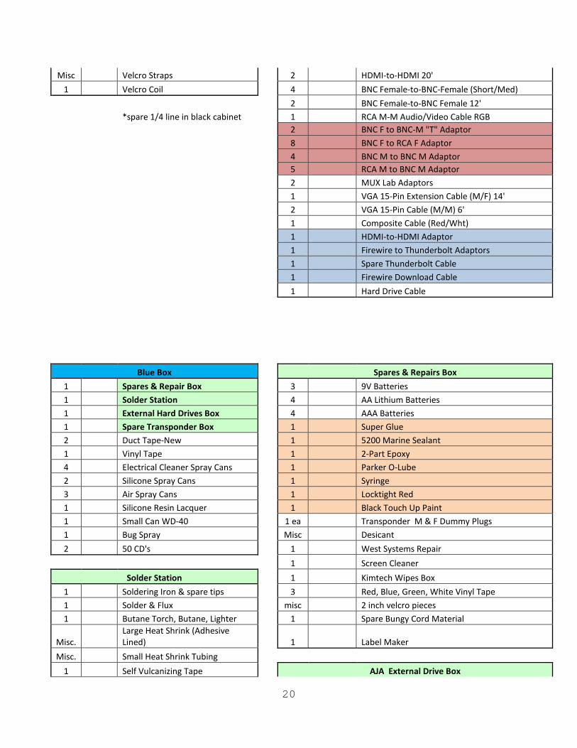
20
Misc Velcro Straps
2 HDMI-to-HDMI 20' 1 Velcro Coil
4 BNC Female-to-BNC-Female (Short/Med)
2 BNC Female-to-BNC Female 12'
*spare 1/4 line in black cabinet
1 RCA M-M Audio/Video Cable RGB
2 BNC F to BNC-M "T" Adaptor
8 BNC F to RCA F Adaptor
4 BNC M to BNC M Adaptor
5 RCA M to BNC M Adaptor
2 MUX Lab Adaptors
1 VGA 15-Pin Extension Cable (M/F) 14'
2 VGA 15-Pin Cable (M/M) 6'
1 Composite Cable (Red/Wht)
1 HDMI-to-HDMI Adaptor
1 Firewire to Thunderbolt Adaptors
1 Spare Thunderbolt Cable
1 Firewire Download Cable
1 Hard Drive Cable
Blue Box
Spares & Repairs Box
1 Spares & Repair Box
3 9V Batteries 1 Solder Station
4 AA Lithium Batteries
1 External Hard Drives Box
4 AAA Batteries 1 Spare Transponder Box
1 Super Glue
2 Duct Tape-New
1 5200 Marine Sealant 1 Vinyl Tape
1 2-Part Epoxy
4 Electrical Cleaner Spray Cans
1 Parker O-Lube 2 Silicone Spray Cans
1 Syringe
3 Air Spray Cans
1 Locktight Red 1 Silicone Resin Lacquer
1 Black Touch Up Paint
1 Small Can WD-40
1 ea Transponder M & F Dummy Plugs 1 Bug Spray
Misc Desicant
2 50 CD's
1 West Systems Repair
1 Screen Cleaner
Solder Station
1 Kimtech Wipes Box 1 Soldering Iron & spare tips
3 Red, Blue, Green, White Vinyl Tape
1 Solder & Flux
misc 2 inch velcro pieces 1 Butane Torch, Butane, Lighter
1 Spare Bungy Cord Material
Misc. Large Heat Shrink (Adhesive Lined)
1 Label Maker
Misc. Small Heat Shrink Tubing 1 Self Vulcanizing Tape
AJA External Drive Box
21
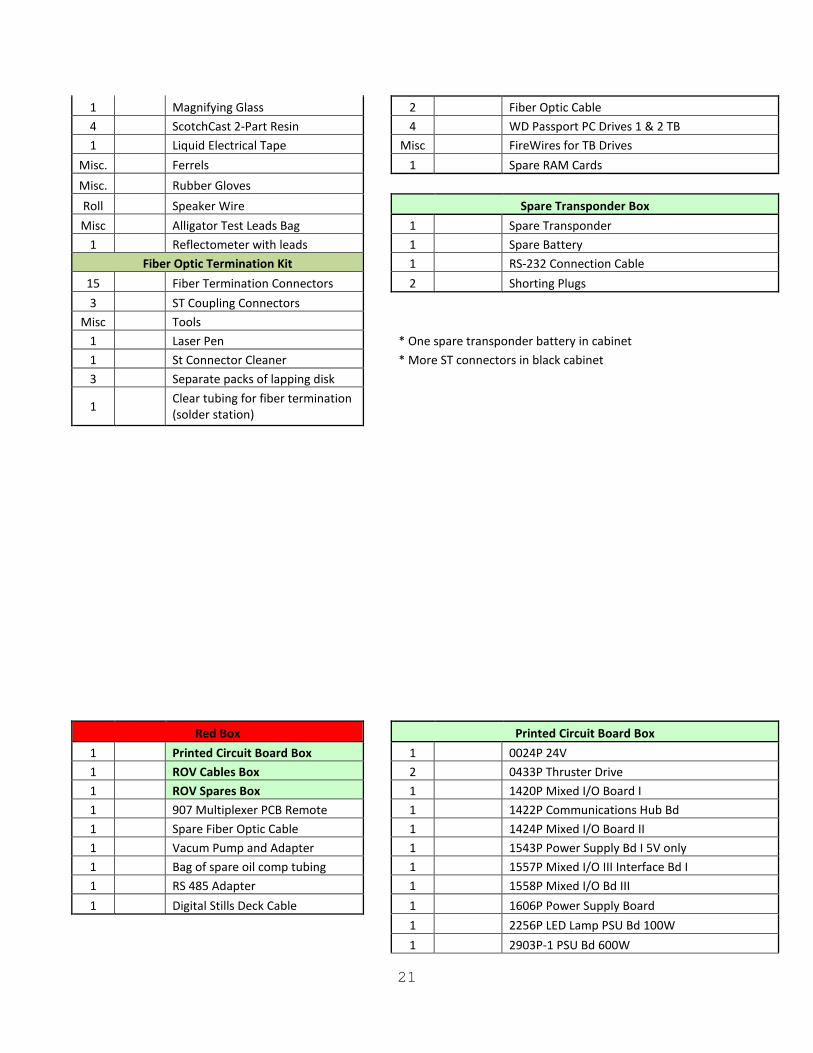
1 Magnifying Glass
2 Fiber Optic Cable 4 ScotchCast 2-Part Resin
4 WD Passport PC Drives 1 & 2 TB
1 Liquid Electrical Tape
Misc FireWires for TB Drives Misc. Ferrels
1 Spare RAM Cards
Misc. Rubber Gloves Roll Speaker Wire
Spare Transponder Box Misc Alligator Test Leads Bag
1 Spare Transponder
1 Reflectometer with leads
1 Spare Battery Fiber Optic Termination Kit
1 RS-232 Connection Cable
15 Fiber Termination Connectors
2 Shorting Plugs 3 ST Coupling Connectors
Misc Tools 1 Laser Pen
* One spare transponder battery in cabinet 1 St Connector Cleaner
* More ST connectors in black cabinet
3 Separate packs of lapping disk
1 Clear tubing for fiber termination (solder station)
Red Box
Printed Circuit Board Box
1 Printed Circuit Board Box
1 0024P 24V 1 ROV Cables Box
2 0433P Thruster Drive
1 ROV Spares Box
1 1420P Mixed I/O Board I 1 907 Multiplexer PCB Remote
1 1422P Communications Hub Bd
1 Spare Fiber Optic Cable
1 1424P Mixed I/O Board II 1 Vacum Pump and Adapter
1 1543P Power Supply Bd I 5V only
1 Bag of spare oil comp tubing
1 1557P Mixed I/O III Interface Bd I 1 RS 485 Adapter
1 1558P Mixed I/O Bd III
1 Digital Stills Deck Cable
1 1606P Power Supply Board
1 2256P LED Lamp PSU Bd 100W
1 2903P-1 PSU Bd 600W
22
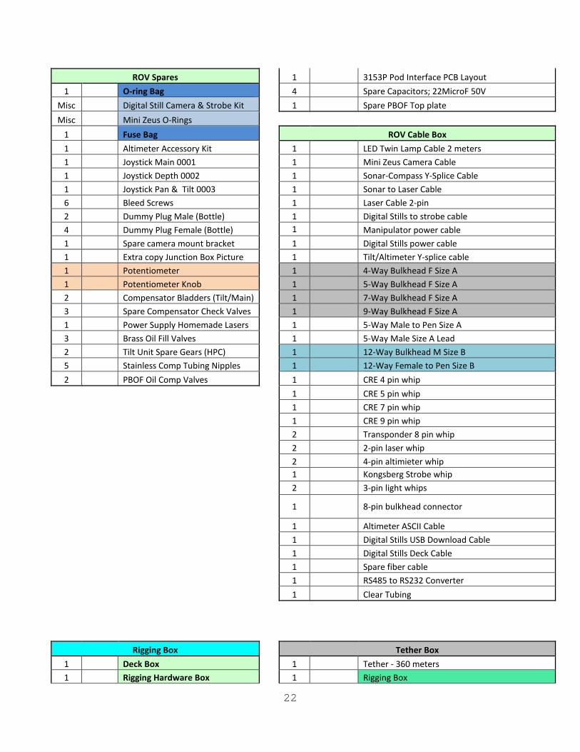
ROV Spares
1 3153P Pod Interface PCB Layout 1 O-ring Bag
4 Spare Capacitors; 22MicroF 50V
Misc Digital Still Camera & Strobe Kit
1 Spare PBOF Top plate Misc Mini Zeus O-Rings
1 Fuse Bag
ROV Cable Box 1 Altimeter Accessory Kit
1 LED Twin Lamp Cable 2 meters
1 Joystick Main 0001
1 Mini Zeus Camera Cable 1 Joystick Depth 0002
1 Sonar-Compass Y-Splice Cable
1 Joystick Pan & Tilt 0003
1 Sonar to Laser Cable 6 Bleed Screws
1 Laser Cable 2-pin
2 Dummy Plug Male (Bottle)
1 Digital Stills to strobe cable 4 Dummy Plug Female (Bottle)
1 Manipulator power cable
1 Spare camera mount bracket
1 Digital Stills power cable 1 Extra copy Junction Box Picture
1 Tilt/Altimeter Y-splice cable
1 Potentiometer
1 4-Way Bulkhead F Size A 1 Potentiometer Knob
1 5-Way Bulkhead F Size A
2 Compensator Bladders (Tilt/Main)
1 7-Way Bulkhead F Size A 3 Spare Compensator Check Valves
1 9-Way Bulkhead F Size A
1 Power Supply Homemade Lasers
1 5-Way Male to Pen Size A 3 Brass Oil Fill Valves
1 5-Way Male Size A Lead
2 Tilt Unit Spare Gears (HPC)
1 12-Way Bulkhead M Size B 5 Stainless Comp Tubing Nipples
1 12-Way Female to Pen Size B
2 PBOF Oil Comp Valves
1 CRE 4 pin whip
1 CRE 5 pin whip
1 CRE 7 pin whip
1 CRE 9 pin whip
2 Transponder 8 pin whip
2 2-pin laser whip
2 4-pin altimieter whip
1 Kongsberg Strobe whip
2 3-pin light whips
1
8-pin bulkhead connector
1 Altimeter ASCII Cable
1 Digital Stills USB Download Cable
1 Digital Stills Deck Cable
1 Spare fiber cable
1 RS485 to RS232 Converter
1 Clear Tubing
Rigging Box
Tether Box
1 Deck Box
1 Tether - 360 meters 1 Rigging Hardware Box
1 Rigging Box
23
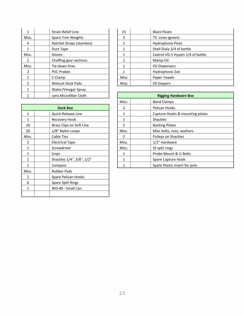
1 Strain Relief Line
15 Black Floats Misc. Spare Trim Weights
2 75' Lines (green)
4 Ratchet Straps (stainless)
1 Hydrophone Pivot 1 Duct Tape
1 Shell Diala 3/4 of bottle
Misc. Gloves
1 Castrol VG-5 Hyspin 1/4 of bottle 2 Chaffing gear sections
1 Manip Oil
Misc. Tie-down lines
1 Oil Dispensers 2 PVC Probes
1 Hydrophone 2x4
1 C-Clamp
Misc Paper Towels 2 Wetsuit Deck Pads
Misc Oil Diapers
1 Water/Vinegar Spray 1 Lens Microfiber Cloth
Rigging Hardware Box
Misc. Band Clamps
Deck Box
2 Pelican Hooks 1 Quick-Release Line
1 Capture Hooks & mounting plates
1 Recovery Hook
2 Shackles 20 Brass Clips on Soft Line
2 Backing Plates
20 1/8" Nylon Loops
Misc. Misc bolts, nuts, washers Misc. Cable Ties
2 Pulleys on Shackles
2 Electrical Tape
Misc. 1/2" Hardware 1 Screwdriver
Misc. SS split rings
1 Snips
1 Probe Mount & U-Bolts 1 Shackles 1/4", 3/8", 1/2"
1 Spare Capture Hook
1 Compass
1 Spare Plastic Insert for pole Misc. Rubber Pads
2 Spare Pelican Hooks 6 Spare Split Rings 1 WD-40 - Small Can
24
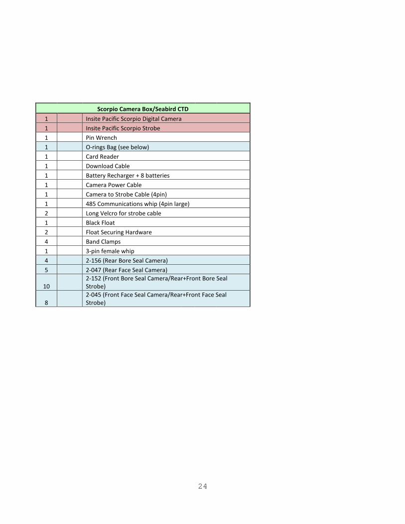
Scorpio Camera Box/Seabird CTD
1 Insite Pacific Scorpio Digital Camera 1 Insite Pacific Scorpio Strobe 1 Pin Wrench 1 O-rings Bag (see below) 1 Card Reader 1 Download Cable 1 Battery Recharger + 8 batteries 1 Camera Power Cable 1 Camera to Strobe Cable (4pin) 1 485 Communications whip (4pin large) 2 Long Velcro for strobe cable 1 Black Float 2 Float Securing Hardware 4 Band Clamps 1 3-pin female whip 4 2-156 (Rear Bore Seal Camera) 5 2-047 (Rear Face Seal Camera)
10 2-152 (Front Bore Seal Camera/Rear+Front Bore Seal Strobe)
8
2-045 (Front Face Seal Camera/Rear+Front Face Seal Strobe)
25
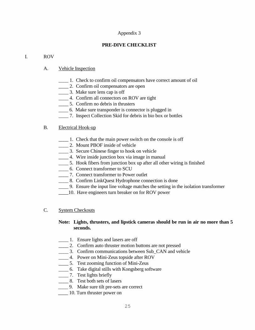
Appendix 3 PRE-DIVE CHECKLIST I. ROV A. Vehicle Inspection ____ 1. Check to confirm oil compensators have correct amount of oil ____ 2. Confirm oil compensators are open ____ 3. Make sure lens cap is off ____ 4. Confirm all connectors on ROV are tight ____ 5. Confirm no debris in thrusters 6. Make sure transponder is connector is plugged in ____ 7. Inspect Collection Skid for debris in bio box or bottles B. Electrical Hook-up ____ 1. Check that the main power switch on the console is off ____ 2. Mount PBOF inside of vehicle ____ 3. Secure Chinese finger to hook on vehicle ____ 4. Wire inside junction box via image in manual ____ 5. Hook fibers from junction box up after all other wiring is finished ____ 6. Connect transformer to SCU ____ 7. Connect transformer to Power outlet ____ 8. Confirm LinkQuest Hydrophone connection is done ____ 9. Ensure the input line voltage matches the setting in the isolation transformer ____10. Have engineers turn breaker on for ROV power C. System Checkouts Note: Lights, thrusters, and lipstick cameras should be run in air no more than 5
seconds. ____ 1. Ensure lights and lasers are off ____ 2. Confirm auto thruster motion buttons are not pressed ____ 3. Confirm communications between Sub_CAN and vehicle ____ 4. Power on Mini-Zeus topside after ROV ____ 5. Test zooming function of Mini-Zeus ____ 6. Take digital stills with Kongsberg software ____ 7. Test lights briefly ____ 8. Test both sets of lasers
____ 9. Make sure tilt pre-sets are correct ____ 10. Turn thruster power on
26
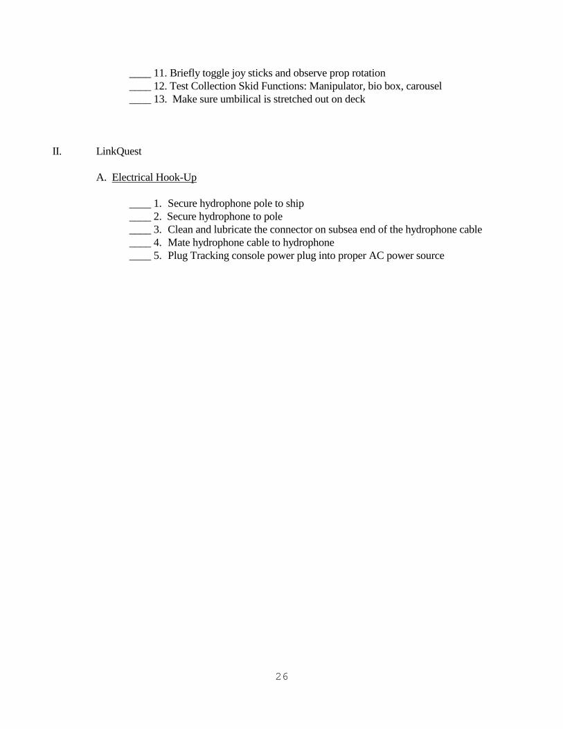
____ 11. Briefly toggle joy sticks and observe prop rotation ____ 12. Test Collection Skid Functions: Manipulator, bio box, carousel ____ 13. Make sure umbilical is stretched out on deck II. LinkQuest A. Electrical Hook-Up ____ 1. Secure hydrophone pole to ship ____ 2. Secure hydrophone to pole ____ 3. Clean and lubricate the connector on subsea end of the hydrophone cable ____ 4. Mate hydrophone cable to hydrophone ____ 5. Plug Tracking console power plug into proper AC power source
27
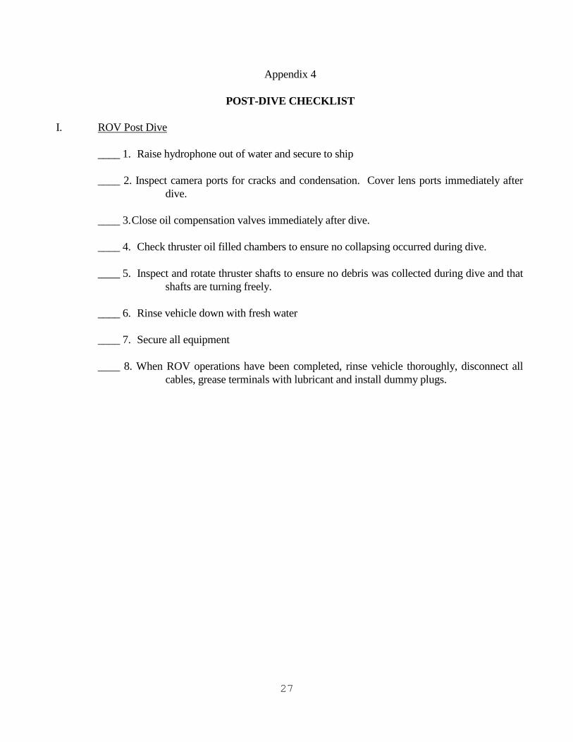
Appendix 4 POST-DIVE CHECKLIST I. ROV Post Dive ____ 1. Raise hydrophone out of water and secure to ship ____ 2. Inspect camera ports for cracks and condensation. Cover lens ports immediately after
dive. ____ 3. Close oil compensation valves immediately after dive. ____ 4. Check thruster oil filled chambers to ensure no collapsing occurred during dive. ____ 5. Inspect and rotate thruster shafts to ensure no debris was collected during dive and that
shafts are turning freely. ____ 6. Rinse vehicle down with fresh water ____ 7. Secure all equipment ____ 8. When ROV operations have been completed, rinse vehicle thoroughly, disconnect all
cables, grease terminals with lubricant and install dummy plugs.
28
Appendix 5
UNCW TROUBLE REPORT FORM P.I./Mission #: ROV Operator: Date: Time: Dive #: Depth: Symptoms and description of obvious malfunction: Trouble shooting steps performed: System Repaired? Time required for repair: Benchstock items expended/parts required:
29
Appendix 6 ROV PIECE WEIGHT LIST
Item Weight lbs Length" Width" Tall" Comments Transformer 211 19 16 25 Toolbox 51 19 17 14 ROV 464 54 32 42 Radio Box 33 21 18 9 Spare Vertran 27 24 16 9 Spare Thruster X2 41 24 16 9 Pilot Station box 100 34 21 20 Tracking Console 80 28 26 36 Science Console 110 37 29 37 ROV Console 90 37 29 37 Red Box 63 28 21 16 Blue Box #1 70 28 21 16 Blue Box #2 56 28 21 16 Downweight 300 12 12 10 Norweigeon Float 5 21 16 16 Jason Wet Weather Gear 15 Small Bag Lance Wet Weather Gear 13 Small Bag
Gear In Tether Box Tether Box 235 72 49 36 Top plus box Oil Box 45 24 20 24 Deck Box 52 24 16 17 Pilot Station (starboard&mount) 35 42 31 24 Tether 624 Fits in tether box Black Floats Tether 15 5 5 6 1 lb each Black Floats Extra 6 5 5 6
Junction Box 18 12 12 5 Plus Cable 10' section
Hydrophone 57 55 7 7 Hydrophone Extension 18 60 2 2 Hydrophone Cable 20 4' diameter Recovery Pole 4 96 1 1 Power Cables X2 26 2' diameter Total Weight Green Lines X2 10 2 small bundles Total Weight GPS Mounting Pole 13 53 1 6 ROV Carpet 15 70 47 0.25 ROV Rubber Matts (2 of them) 32 36 36 0.5
30
2954
Collection Skid Skid 300 54 33 27 Blue Box Spares 28 21 16 Topside unit 24 22 24 8
Gear not needed on some missions Hydrophone Pole 240 20 6 Heavy Downweight 450 8 8 27
31
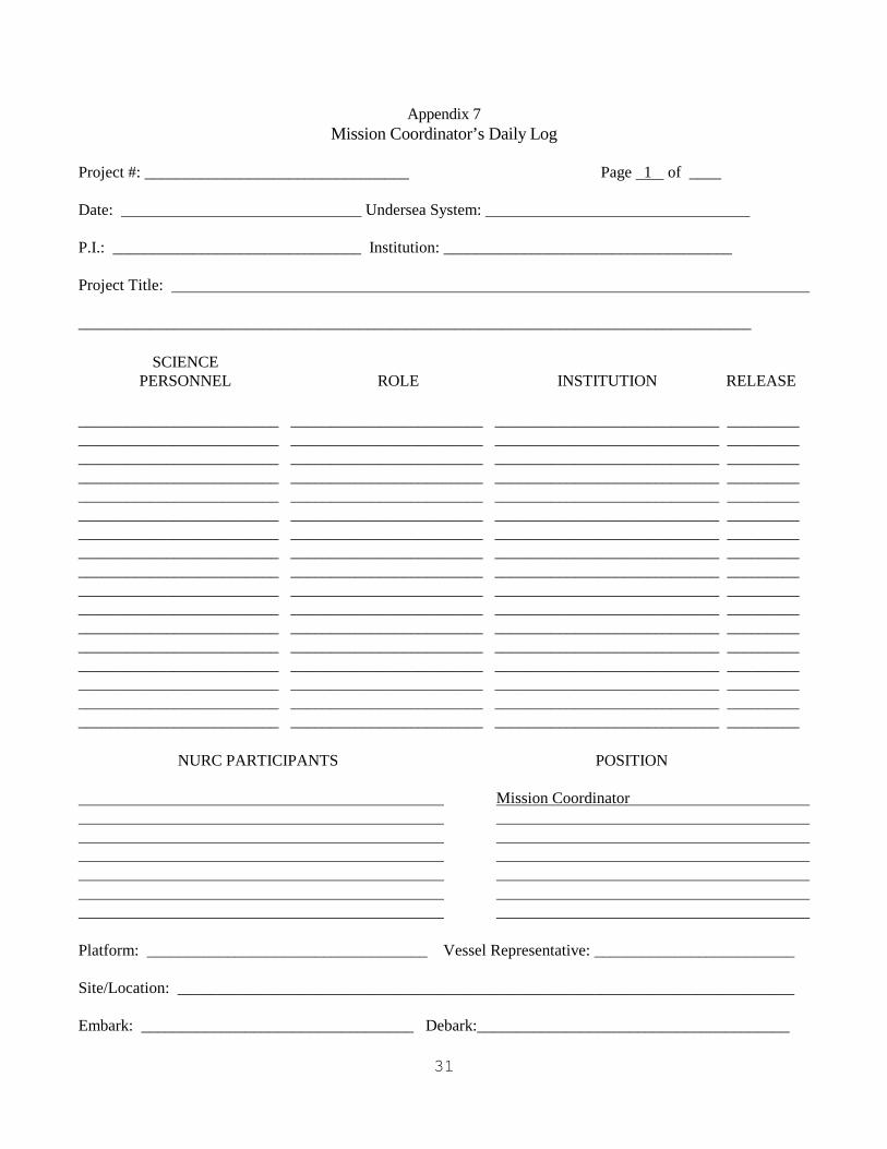
Appendix 7 Mission Coordinator’s Daily Log
Project #: _________________________________ Page 1 of ____ Date: ______________________________ Undersea System: _________________________________ P.I.: _______________________________ Institution: ____________________________________ Project Title: ____________________________________________________________________________________
SCIENCE PERSONNEL ROLE INSTITUTION RELEASE
_________________________ ________________________ ____________________________ _________ _________________________ ________________________ ____________________________ _________ _________________________ ________________________ ____________________________ _________ _________________________ ________________________ ____________________________ _________ _________________________ ________________________ ____________________________ _________ _________________________ ________________________ ____________________________ _________ _________________________ ________________________ ____________________________ _________ _________________________ ________________________ ____________________________ _________ _________________________ ________________________ ____________________________ _________ _________________________ ________________________ ____________________________ _________ _________________________ ________________________ ____________________________ _________ _________________________ ________________________ ____________________________ _________ _________________________ ________________________ ____________________________ _________ _________________________ ________________________ ____________________________ _________ _________________________ ________________________ ____________________________ _________ _________________________ ________________________ ____________________________ _________ _________________________ ________________________ ____________________________ _________
NURC PARTICIPANTS POSITION Mission Coordinator Platform: ___________________________________ Vessel Representative: _________________________ Site/Location: _____________________________________________________________________________ Embark: __________________________________ Debark:_______________________________________

32
Mission Coordinator’s Daily Log (continued)
Cruise Day # ____________________________ Date: / /200
TIME EVENT
33
Appendix 8
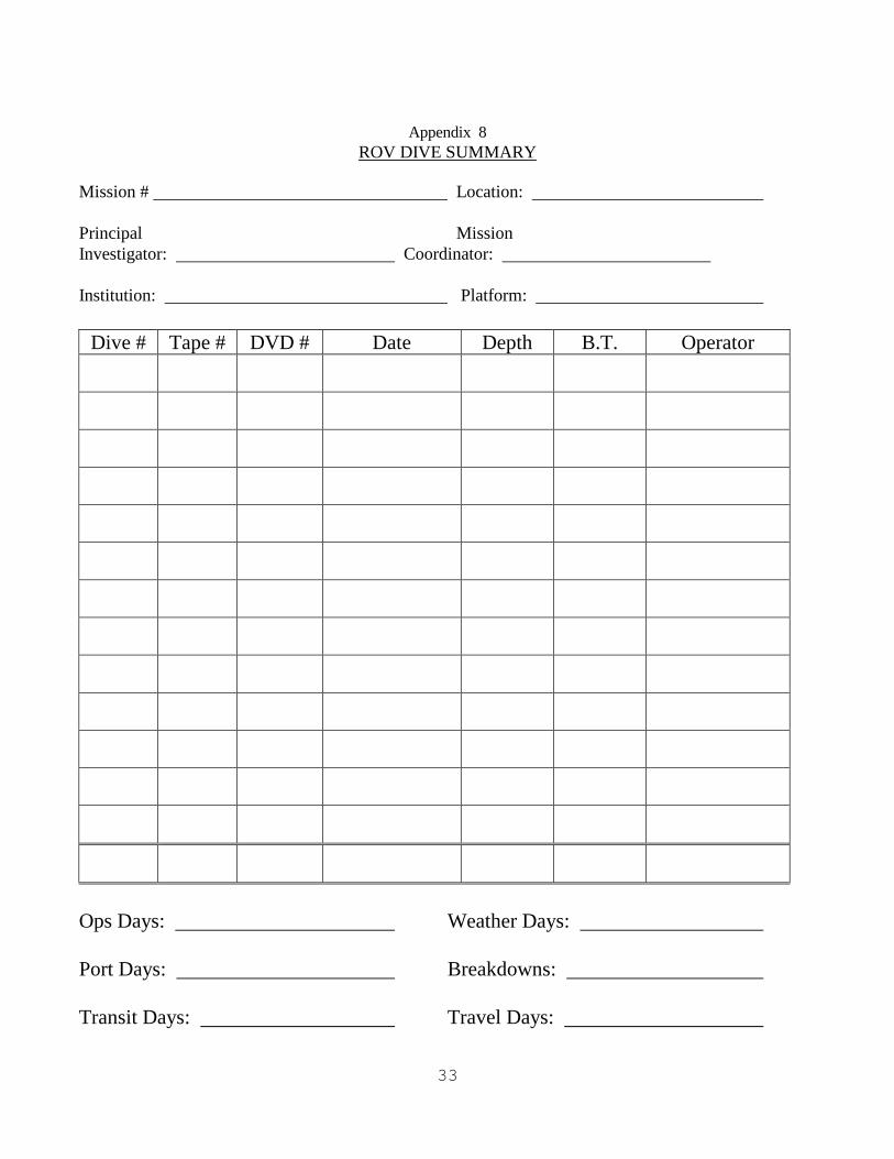
ROV DIVE SUMMARY
Mission # Location: Principal Mission Investigator: Coordinator: Institution: Platform:
Dive # Tape # DVD # Date Depth B.T. Operator
Ops Days: Weather Days: Port Days: Breakdowns: Transit Days: Travel Days:
34
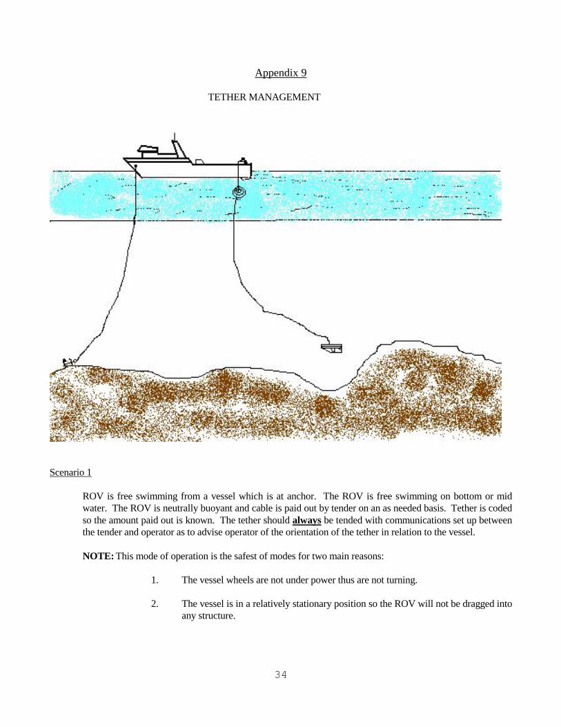
Appendix 9 TETHER MANAGEMENT
Scenario 1 ROV is free swimming from a vessel which is at anchor. The ROV is free swimming on bottom or mid
water. The ROV is neutrally buoyant and cable is paid out by tender on an as needed basis. Tether is coded so the amount paid out is known. The tether should always be tended with communications set up between the tender and operator as to advise operator of the orientation of the tether in relation to the vessel.
NOTE: This mode of operation is the safest of modes for two main reasons: 1. The vessel wheels are not under power thus are not turning. 2. The vessel is in a relatively stationary position so the ROV will not be dragged into
any structure.
35
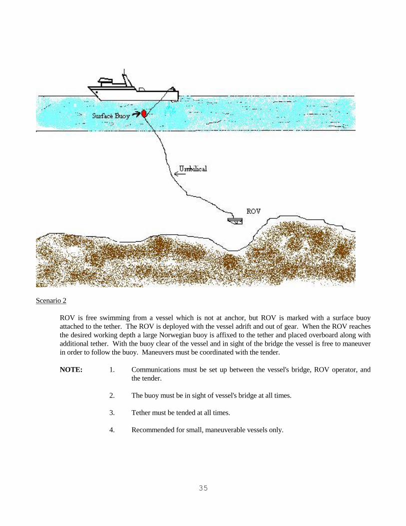
Scenario 2 ROV is free swimming from a vessel which is not at anchor, but ROV is marked with a surface buoy
attached to the tether. The ROV is deployed with the vessel adrift and out of gear. When the ROV reaches the desired working depth a large Norwegian buoy is affixed to the tether and placed overboard along with additional tether. With the buoy clear of the vessel and in sight of the bridge the vessel is free to maneuver in order to follow the buoy. Maneuvers must be coordinated with the tender.
NOTE: 1. Communications must be set up between the vessel's bridge, ROV operator, and
the tender. 2. The buoy must be in sight of vessel's bridge at all times. 3. Tether must be tended at all times. 4. Recommended for small, maneuverable vessels only.
36
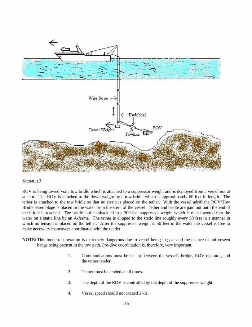
Scenario 3 ROV is being towed via a tow bridle which is attached to a suppressor weight and is deployed from a vessel not at anchor. The ROV is attached to the down weight by a tow bridle which is approximately 60 feet in length. The tether is attached to the tow bridle so that no strain is placed on the tether. With the vessel adrift the ROV/Tow Bridle assemblage is placed in the water from the stern of the vessel. Tether and bridle are paid out until the end of the bridle is reached. The bridle is then shackled to a 300 lbs. suppressor weight which is then lowered into the water on a static line by an A-frame. The tether is clipped to the static line roughly every 50 feet in a manner in which no tension is placed on the tether. After the suppressor weight is 50 feet in the water the vessel is free to make necessary maneuvers coordinated with the tender. NOTE: This mode of operation is extremely dangerous due to vessel being in gear and the chance of unforeseen
hangs being present in the tow path. Pre-dive coordination is, therefore, very important. 1. Communications must be set up between the vessel's bridge, ROV operator, and
the tether tender. 2. Tether must be tended at all times. 3. The depth of the ROV is controlled by the depth of the suppressor weight. 4. Vessel speed should not exceed 2 kts.

37
Scenario 4 ROV is attached to a suppressor weight via the tether and is deployed from a vessel which is at anchor.
This method of deployment is very effective in strong current situations by alleviating the drag created by the current on the tether. The ROV is placed in the water and starts to descend in the water column. After the working depth is reached or 200 feet of tether is paid out the tether is affixed to a static line just above a suppressor weight. The suppressor weight is then lowered into the water via an A-frame. The tether is then clipped to the static line every 50 feet. The suppressor weight can be lowered to a depth not to exceed the working depth minus 30 feet. This will keep the suppressor weight from pinning the ROV between it and the bottom.
NOTE: 1. Communications must be set up between the vessel's bridge, ROV operator, and
the tender. 2. Tether must be tended at all times. 3. The circumference of travel by the ROV is controlled by the depth of the
suppressor weight. 4. Vessel crew shall notify the ROV operator and tender of major current changes,
wind shifts, or loss of dynamic positioning.