remote multi-layer soil temperature monitoring system...
TRANSCRIPT

Sensors & Transducers, Vol. 164, Issue 2, February 2014, pp. 107-113
107
SSSeeennnsssooorrrsss &&& TTTrrraaannnsssddduuuccceeerrrsss
© 2014 by IFSA Publishing, S. L. http://www.sensorsportal.com
Remote Multi-layer Soil Temperature Monitoring System Based on GPRS
Ming Kuo CHEN, Wen Bin LI, Jiang Ming KAN
School of Technology, Beijing Forestry University, Beijing 100083, China
Tel.: 010-62338139, fax: 010-62338139 E-mail: [email protected]
Received: 29 October 2013 /Accepted: 28 November 2013 /Published: 28 February 2014 Abstract: There is the temperature difference between the upper and lower layer of the shallow soil in the forest. It is a potential energy that can be harvested by thermoelectric generator for the electronic device in the forest. The temperature distribution at different depths of the soil is the first step for thermoelectric generation. A remote multi-layer soil temperature monitoring system based on GPRS is proposed in this paper. The MSP430F149 MCU is used as the main controller of multi-layer soil temperature monitoring system. A temperature acquisition module is designed with DS18B20 and 4 core shielded twisted-pair cable. The GPRS module sends the measured data to remote server through wireless communication network. From the experiments in the campus of Beijing Forestry University, the maximum error T of measured temperature in this system is 0.2°C by comparing with professional equipment in the same condition. The results of the experiments show that the system can accurately realize real-time monitoring of multi-layer soil temperature, and the data transmission is stable and reliable. Copyright © 2014 IFSA Publishing, S. L. Keywords: GPRS, SIM300, Wireless transmission, Temperature sensor. 1. Introduction
The surface temperature of soil is one of the important environmental factors for plant growth. The temperature variation is connected with seasons, weather and time. It is great significance to grasp the surface temperature variation of soil for plant cultivation management. In addition, the power supply problem is urgent to be solved along with the wireless sensor is continuously popularized and applied in the agroforestry environmental monitoring. How to use the energy of the surrounding environment is a new research hotspot [1, 2]. Currently, the conversion and utilization of environment energy mainly involves solar energy, wind energy, vibration energy, light energy,
electromagnetic wave, piezoelectric energy and thermal energy, etc [3-5]. Soil is a huge thermal energy storage, there has been a lot of mature technologies (such as geothermal heat pumps, etc.) on geothermal utilization, but these devices are large and complex, the cost of equipment and construction is high, and they also need external power supply, therefore, it cannot be used in the forest. Heat can directly transfer into electricity by semiconductor thermoelectric generator in spite of only a slight difference in temperature, it is a green energy technology with a large wide scope of application. This technology can be used to transform soil thermal energy of the shallow soil into electric energy to storage and use, so it is of great significance for micro power consumption devices to supply power
Article number P_1839

Sensors & Transducers, Vol. 164, Issue 2, February 2014, pp. 107-113
108
such as wireless sensor. But in order to design reasonable thermoelectric generation system, we need to know the shallow soil temperature variation, to observe daily and annual variation of soil temperature in fixed-point [6, 7].
At present, there are many soil temperature measuring instruments on the market, such as the non-contact thermometer using the infrared spectra, and the thermistor thermometer using PT100 thermistor. The cost is high to use infrared spectrum measurement and only soil surface temperature can be measured. PT100 thermistor parameter required calibration before measurement [8]. Most of soil temperature measuring instruments mainly deal with data acquisition, storage and PC communication, it is inconvenient to charge and replace the battery, multi-point temperature measurement mainly relies on the multi-channel sensors, the product is not flexible and can not be used for real-time data transmission.
In this paper, aiming at the power supply requirements of the soil temperature measuring instrument, multi-layer soil temperature accurate real-time acquisition and rapid transmission, the existing solar power is used to supply power for multi-layer soil temperature monitoring system in order to study the development of thermoelectric power generation systems to get more energy, so as to ensure a large number of wireless sensor networks in the forest can operate continuously and stably.
2. System Structure and Module
Multi-layer soil temperature monitoring system uses MSP430F149 MCU as controller which has external expansion modules such as real-time clock module, temperature acquisition module, data storage module and GPRS module. The solar power system is used for power supply to make sure the field temperature data acquisition and storage as well as remote data real-time, uninterrupted and accurate transmission. The system structure diagram is shown in Fig. 1.
Fig. 1. System structure diagram.
2.1. Temperature Acquisition Module
In this study, DS18B20 digital temperature sensor produced by the DALLAS semiconductor company
is used in the temperature acquisition module. External power supply is connected to VDD pin to provide power. The I/O line needn’t to be pulled, so the insufficient power supply does not exist which ensures the accuracy of conversion. Five DS18B20 sensors articulated with the bus in this module compose multi-point temperature measurement system [9]. Temperature acquisition module schematic is shown in Fig. 2.
Fig. 2. Temperature acquisition module schematic.
When measure the deeper soil temperature in actual, 4 core shielded twisted-pair cable are used as temperature measurement cables, one pair cable is connected to the ground and the signal line, another group is connected to VCC and ground. The shielding layer on the source side single point is connected to ground, which could reduce bus capacitance and avoid signal waveform distortion. The soil is excavated by soil augers when the soil temperature need to be measured, the temperature cables is buried into the soil. The measurement points are arranged by the actual needs. 2.2. Wireless Transmission Module
Wireless data transmission was achieved with SIM300 controlled by MSP430F149 MCU in this study. Texas Instruments MSP430F149 using the latest low-power technology is a new type of mixed-signal processor, it integrates a lot of peripheral module into slice and is particularly suitable for the design and development of monolithic system. Its storage space fully meets the needs of programs and data saving with 60 k byte Flash ROM and 2 k byte RAM. SIM300 is GPRS module launched by SIMCOM company which has small size and low power consumption. TCP/IP protocol stack is internally integrated to provide a common control command AT [10]. SIM card that can be accessed by CMNET is embedded in its holder and connected to SIM300 with GPRS function. After the system is powered on, P1.1 pin of MSP430F149 starts the SIM300. When NetworkLED network lights flicker frequency is 64ms on/800ms off, it shows the SIM300 is searching for networks; When NetworkLED network lights flicker frequency becomes 64 ms on/3000 ms off, it shows network connection is successful. MSP430F149 sends AT

Sensors & Transducers, Vol. 164, Issue 2, February 2014, pp. 107-113
109
commands through the serial port to control SIM300, SIM300 feeds conformation back to MSP430F149
through serial port. Wireless transmission module circuit is shown in Fig. 3.
GND 1
VPP 2
IO3
CLK4
RST5
VDD6
JP12
SIM CARD
1nF
C65
220nF
C64
P3.6/UTXD134
P3.7/URXD1 35
P1.2 14
P1.315
P1.5 17P1.4 16
P1.618
P1.1 13
XIN8
XOUT9
XT2IN53
XT2OUT52
VDD
U1
MSP430F149
VEXT17
RXD40
TXD42
RTS44
CTS46
DTR38
RI48 SIMVDD 19
SIMRST 25
SIMCLK23SIMI/O 21
VBAT
NetworkLED 30
PWRKEY 34
U2
SIM300
R23 22
R19 22
R21 22
R18 10k1kR24
1k
R17DS2
LED3
+3.3V31
2
Q1NPN 3904
3
1
2
Q2NPN 3904
1kR31
R1R2R26R27R28R29R30
VBAT
X38M
C12
12p
C11
12p
X232768Hz
+3.3V
Fig. 3. Wireless transmission module circuit. 2.3. Voltage Regulator Circuit
SIM300 power supply voltage is 3.4 V-4.5 V, its start-up and launching requires strong current. When current consumption rises to typical peak 2 A, its transmission pulse fluctuations can cause voltage drop, so the power supply must afford sufficient current 2 A. This study using LM2576 as the step-down switching regulator, whose output voltage is
5 V and input voltage range is 8 V-40 V, it is with a 3 A load drive capability, when its input terminal is connected to the 12 V solar power supply system, it can fully meet the working requirements of the system [11]. Chip 1N4007 connected to output of LM2576 provides the working voltage of 4.3 V to SIM300. AMS1117 provides 3.3 V working voltage to the MSP430F149.Voltage Regulator Circuit is shown in Fig. 4.
Fig. 4. Voltage regulator circuit. 2.4. Solar Power Supply System
Solar power supply system consists of solar panel, charge and discharge control circuit, voltage regulator circuit and lithium ion battery. The principle block diagram is shown in Fig. 5. Solar panels converse solar radiation into electrical energy directly with the photoelectric effect. Voltage regulator circuit stabilizes the output voltage of solar panels to meet the charge and discharge control circuit [12]. Charge and discharge control circuit prevents overcharge, reflux and similar things by completing lithium ion battery charging and
discharging. In this study, because the sunlight is very dim and crown density is high in the forest, the power panel switch open circuit voltage of 21.2 V and peak power of 30 W are chosen. The lithium ion battery with a capacity of 2200 mAh and voltage of 12 V is used to ensure soil temperature monitoring system working continuously and stably.
Fig. 5. Solar energy power supply system principle block diagram.
Sensors & Transducers, Vol. 164, Issue 2, February 2014, pp. 107-113
110
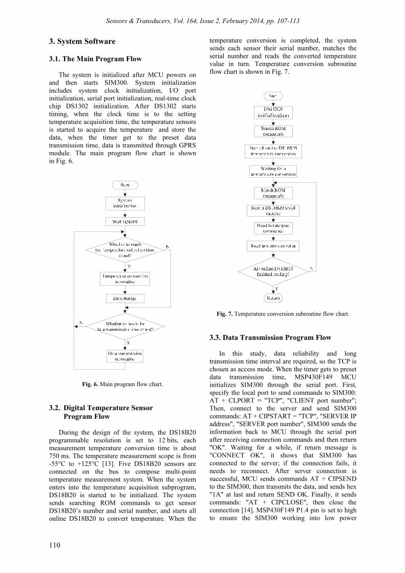
3. System Software 3.1. The Main Program Flow
The system is initialized after MCU powers on and then starts SIM300. System initialization includes system clock initialization, I/O port initialization, serial port initialization, real-time clock chip DS1302 initialization. After DS1302 starts timing, when the clock time is to the setting temperature acquisition time, the temperature sensors is started to acquire the temperature and store the data, when the timer get to the preset data transmission time, data is transmitted through GPRS module. The main program flow chart is shown in Fig. 6.
Fig. 6. Main program flow chart. 3.2. Digital Temperature Sensor
Program Flow
During the design of the system, the DS18B20 programmable resolution is set to 12 bits, each measurement temperature conversion time is about 750 ms. The temperature measurement scope is from -55°C to +125°C [13]. Five DS18B20 sensors are connected on the bus to compose multi-point temperature measurement system. When the system enters into the temperature acquisition subprogram, DS18B20 is started to be initialized. The system sends searching ROM commands to get sensor DS18B20’s number and serial number, and starts all online DS18B20 to convert temperature. When the
temperature conversion is completed, the system sends each sensor their serial number, matches the serial number and reads the converted temperature value in turn. Temperature conversion subroutine flow chart is shown in Fig. 7.
Fig. 7. Temperature conversion subroutine flow chart. 3.3. Data Transmission Program Flow
In this study, data reliability and long transmission time interval are required, so the TCP is chosen as access mode. When the timer gets to preset data transmission time, MSP430F149 MCU initializes SIM300 through the serial port. First, specify the local port to send commands to SIM300: AT + CLPORT = "TCP", "CLIENT port number"; Then, connect to the server and send SIM300 commands: AT + CIPSTART = "TCP", "SERVER IP address", "SERVER port number", SIM300 sends the information back to MCU through the serial port after receiving connection commands and then return "OK". Waiting for a while, if return message is "CONNECT OK", it shows that SIM300 has connected to the server; if the connection fails, it needs to reconnect. After server connection is successful, MCU sends commands AT + CIPSEND to the SIM300, then transmits the data, and sends hex "1A" at last and return SEND OK. Finally, it sends commands: "AT + CIPCLOSE", then close the connection [14]. MSP430F149 P1.4 pin is set to high to ensure the SIM300 working into low power

Sensors & Transducers, Vol. 164, Issue 2, February 2014, pp. 107-113
111
consumption mode. Data transmission program flow chart is shown in Fig. 8. 4. Software in Server Receiving Terminal
In this study, the data of the system is received with a computer which is a server on the internet with a public IP address. Visual Basic is used to create a PC monitor interface which draws time curves of temperature changing of different layers of soil with the GPRS transmission data. SQL Server is used to manage the database.
Fig. 8. Data transmission program flow chart.
5. System Performance Testing
Multi-layer soil temperature monitoring system integrates MSP430F149 MCU, real-time clock module, data storage module, GPRS module on a PCB board that will be loaded into the processed instrument housing, and solar panels is fixed to the top of the housing. In the practical application, DS18B20 is connected to the 4 core shielded twisted-pair cable, which is sealed by silicone adhesive sealant with moisture, shock, anti-leakage performance.
In this study, we compare the measured temperature with the JWSK-SC handheld
temperature and humidity meter in the same environment, which is shown in Table 1, the maximum error T of measured temperature was 0.2°С. The system has been applied in woodland of Beijing Forestry University campus for real-time monitoring of daily soil temperature and transferring data to servers on the Internet.
Table 1. Experimental data of maximum error of measured temperature.
0T *(°C) 0T *(°C) T *(°C)
-9.3 -9.1 0.2
-6.1 -6.1 0
-3.6 -3.5 0.1
-0.8 -0.8 0
5.1 5.1 0
11.9 11.8 0.1
23.0 23.1 0.1
where * 0T is the system measurement temperature; *1T is
the JWSK-SC handheld temperature and humidity meter measurement temperature; * T is the Measurement error
0 1| |T T T .
6. Test Data Analysis
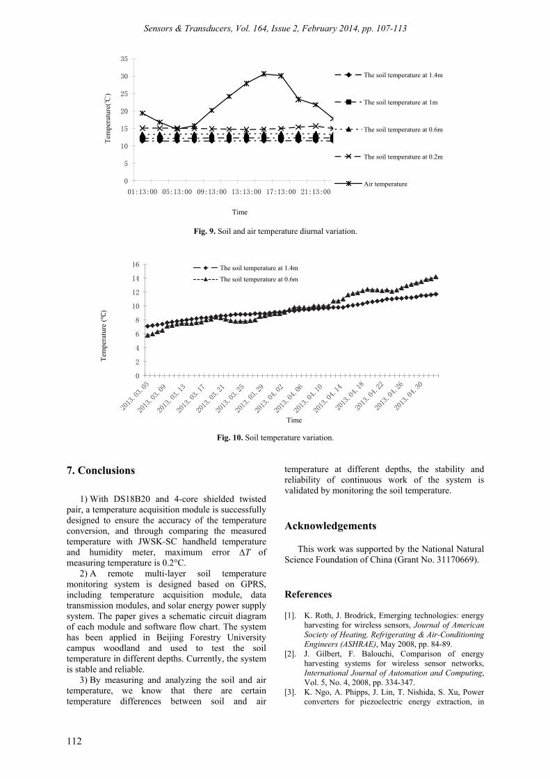
The system reliability was verified by analyzing the temperature value through real-time monitoring on PC. Test data was collected every two hours. The soil and air temperature were measured at depth of 1.4 m, 1 m, 0.6 m, 0.2 m.
April 30, 2013 soil and air temperature diurnal variation is shown in Fig. 9. The average temperature at 1.4 m, 1 m, 0.6 m and 0.2 m was 11.4°C, 12.3°C, 13.4°C and 15.1°C. The upper soil temperature was higher than the lower soil temperature. The lowest air temperature was 14.8°C, the highest air temperature was 30.6°C in the day and night. Fig. 9 shows that the lowest air temperature was close to the soil temperature at 0.2 m. The difference between the highest air temperature and the lowest soil temperature was 19.2°C. We can know that there are certain temperature differences between soil temperature and air temperature at different depths.
Figure 10 shows the soil temperature variation from March 5, 2013 to May 3, 2013. We can know the soil temperature at 1.4m and 0.6m is on the rise with the weather warms up. The upper soil temperature is lower than the lower soil temperature before April, the upper soil temperature is higher than the lower soil temperature after April, which is consistent with the reference [6] [15] and validates the stability and reliability of continuous work of the system, which also illustrates that the conversion time of the upper and the lower soil temperature is about between the end of march to early April in Beijing.
Sensors & Transducers, Vol. 164, Issue 2, February 2014, pp. 107-113
112
0
5
10
15
20
25
30
35
01:13:00 05:13:00 09:13:00 13:13:00 17:13:00 21:13:00
Time
Tem
pera
ture
(℃)
The soil temperature at 1.4m
The soil temperature at 1m
The soil temperature at 0.6m
The soil temperature at 0.2m
Air temperature
Fig. 9. Soil and air temperature diurnal variation.
0
2
4
6
8
10
12
14
16
Tem
pera
ture
()
Time
The soil temperature at 1.4m
The soil temperature at 0.6m
Fig. 10. Soil temperature variation.
7. Conclusions
1) With DS18B20 and 4-core shielded twisted
pair, a temperature acquisition module is successfully designed to ensure the accuracy of the temperature conversion, and through comparing the measured temperature with JWSK-SC handheld temperature and humidity meter, maximum error T of measuring temperature is 0.2°C.
2) A remote multi-layer soil temperature monitoring system is designed based on GPRS, including temperature acquisition module, data transmission modules, and solar energy power supply system. The paper gives a schematic circuit diagram of each module and software flow chart. The system has been applied in Beijing Forestry University campus woodland and used to test the soil temperature in different depths. Currently, the system is stable and reliable.
3) By measuring and analyzing the soil and air temperature, we know that there are certain temperature differences between soil and air
temperature at different depths, the stability and reliability of continuous work of the system is validated by monitoring the soil temperature. Acknowledgements
This work was supported by the National Natural Science Foundation of China (Grant No. 31170669). References [1]. K. Roth, J. Brodrick, Emerging technologies: energy
harvesting for wireless sensors, Journal of American Society of Heating, Refrigerating & Air-Conditioning Engineers (ASHRAE), May 2008, pp. 84-89.
[2]. J. Gilbert, F. Balouchi, Comparison of energy harvesting systems for wireless sensor networks, International Journal of Automation and Computing, Vol. 5, No. 4, 2008, pp. 334-347.
[3]. K. Ngo, A. Phipps, J. Lin, T. Nishida, S. Xu, Power converters for piezoelectric energy extraction, in

Sensors & Transducers, Vol. 164, Issue 2, February 2014, pp. 107-113
113
Proceedings of the ASME International Mechanical Engineering Congress and Exposition, Aerospace Division, 2006, Paper No. IMECE2006-14343, pp. 597-602.
[4]. A. Kasyap, Development of MEMS-based piezoelectric cantilever arrays for vibrational energy harvesting, Ph. D Aerospace Engineering, University of Florida, 2007.
[5]. F. Liu, A. Phipps, S. Horowitz, L. Cattafesta, T. Nishida, M. Sheplak, Acoustic energy harvesting using an electromechanical Helmholtz resonator, Journal of the Acoustical Society of America, Vol. 123, Issue 4, 2008, pp. 1983–1990.
[6]. B Zhao, J Chen, X Zhang, A kind of ground thermoelectric generation device, EP2011103200468, May 15, 2012.
[7]. Y. Song, J. Wang, X. Qiao, W. Zheng. X. Zhang, Development of multi-functional soil temperature measuring instrument, Journal of Agricultural Mechanization Research, No. 9, 2010, pp. 80-84.
[8]. X. Qiao, X. He, X. Du, H. Tian, C. Wang, Design and implement of multi-point soil temperature measurement, Journal of Shenyang Agricultural University, Vol. 37, No. 3, 2006, pp. 278-281.
[9]. S. Wang, X. Li, Design of wireless multi-spots temperature measurement system based on nRF905
and DS18B20, Telecom Power Technology, Vol. 28, No. 6, 2011, pp. 55-57.
[10]. L. Wu, L. Li, S. Zhao, X. Wang, Design and development of remote ECG monitoring system based on SIM300, Journal of Harbin University of Science and Technology, Vol. 15, No. 6, 2010, pp. 112-115.
[11]. LM2576. LM2576/LM2576HV Series SIMPLE SWITCHER 3A Step-Down Voltage Regulator, National Semiconductor Corporation, 2004.
[12]. B. Zhang, W. Li, X. Wang, Z. Hao, Remote dynamic monitoring system for diameter at breast height of tree and forestry information, Hunan Agricultural Sciences, No. 21, 2011, pp. 124-128.
[13]. Q. Zhu, X. Wang, L. Huang, Multi-channel temperature collection system based on DS18B20, Marine Electric & Electronic Technology, Vol. 29, No. 2, 2009, pp. 7-9.
[14]. J. Chen, S. Du, T. Liu, L. Zhao, F. Zhang, Design of remote data acquisition and transmission terminal based on SIM300C, Microcomputer & Its Applications, No. 23, 2009, pp. 7-9.
[15]. S. Zhou, C. Zhang, X Wang, X Wu, Simulation of soil temperature with a multi-layer model and its verification, Journal of Nanjing Institute of Meteorology, Vol. 27, No. 2, 2004, pp. 200-209.
___________________
2014 Copyright ©, International Frequency Sensor Association (IFSA) Publishing, S. L. All rights reserved. (http://www.sensorsportal.com)