reliability analysis data manual - nyiso · nyiso reliability analysis data manual system and...
TRANSCRIPT

MANUAL 24
Reliability Analysis Data Manual
December 2016

Version: 3.2
Effective Date: 12/01/2016
Committee Acceptance: 06/16/2016
This document was prepared by: System and Resource Planning
New York Independent System Operator 10 Krey Boulevard Rensselaer, NY 12144 (518) 356-6060 www.nyiso.com
Disclaimer The information contained within this manual, along with the other NYISO manuals, is intended to be used for informational purposes and is subject to change. The NYISO is not responsible for the user’s reliance on these publications or for any erroneous or misleading material.
©Copyright 1999-2016 New York Independent System Operator

N Y I S O R E L I A B I L I T Y A N A L Y S I S D A T A M A N U A L
iii System and Resource Planning Version 3.2 12/01/2016
Table of Contents
Table of Figures ......................................................................................................................... iv Table of Tables .......................................................................................................................... iv Revision History .......................................................................................................................... v
1. Overview ................................................................................................................................. 1-1 1.1 Purpose and Scope ................................................................................................................... 1-1 1.2 NYISO Data Classification ........................................................................................................ 1-2 1.3 Treatment of Data ..................................................................................................................... 1-3
1.3.1 Critical Energy Infrastructure Information (CEII) ......................................................... 1-3 1.3.2 Confidential Data ........................................................................................................ 1-4 1.3.3 Data Requests ............................................................................................................ 1-4
1.4 Reliability Analysis Databases .................................................................................................. 1-4 1.4.1 NYISO Database ........................................................................................................ 1-4 1.4.2 FERC Form 715: Annual Transmission Planning and Evaluation Report .................. 1-5 1.4.3 ERAG MMWG Steady State Base Cases .................................................................. 1-6 1.4.4 NPCC Steady State Base Cases ................................................................................ 1-6
1.5 Bulk Power Transmission Facilities........................................................................................... 1-6
2. NYISO Database Update Procedures .................................................................................. 2-1 2.1 Annual Database Update Process ............................................................................................ 2-1 2.2 Facility Owner Updates ............................................................................................................. 2-6
2.2.1 Data Notification Requirements .................................................................................. 2-7 2.2.2 New York Transmission Owner Data Coordinator Requirements .............................. 2-7 2.2.3 NYCA Facility Owner Requirements........................................................................... 2-7
2.3 Generation Capability Reporting ............................................................................................... 2-8 2.3.1 Real Power Capability ................................................................................................ 2-8
2.3.1.1 Real Power Capability Demonstration Exemptions ........................................... 2-9 2.3.2 Reactive Power Capability .......................................................................................... 2-9
2.3.2.1 Reactive Power Capability Demonstration Exemptions .................................. 2-10 2.4 NYISO Data Screening Procedure ......................................................................................... 2-11 2.5 NYISO Model Validation Procedure ........................................................................................ 2-11
2.5.1 NERC MOD-025-2 .................................................................................................... 2-11 2.5.2 NERC MOD-026-1 and NERC MOD-027-1 .............................................................. 2-11 2.5.3 NERC MOD-033-1 .................................................................................................... 2-12
3. System Network Representation ......................................................................................... 3-1 3.1 Network Model Data .................................................................................................................. 3-1 3.2 Facility Ratings .......................................................................................................................... 3-1 3.3 Load Data .................................................................................................................................. 3-2 3.4 Dynamics Model Data ............................................................................................................... 3-3
3.4.1 Generator Dynamics Data .......................................................................................... 3-3 3.4.2 Generator Controls Dynamics Data ............................................................................ 3-4 3.4.3 Network Dynamics Data ............................................................................................. 3-4 3.4.4 Load Dynamics Model Data ........................................................................................ 3-4
3.5 Contingency Data ...................................................................................................................... 3-4 3.5.1 Steady State Contingency Modeling Data .................................................................. 3-4 3.5.2 Dynamic Contingency Modeling Data......................................................................... 3-5
3.6 Short Circuit Data ...................................................................................................................... 3-5
4. Real-Time System Representation ...................................................................................... 4-1 4.1 Real-Time System Representation Data .................................................................................. 4-1

N Y I S O R E L I A B I L I T Y A N A L Y S I S D A T A M A N U A L
System and Resource Planning iv Version 3.2 12/01/2016
4.1.1 System Network Representation Data........................................................................ 4-1 4.1.2 Facilities Ratings Data ................................................................................................ 4-2 4.1.3 Dynamic Rating Updates ............................................................................................ 4-2
4.2 Operating System Representation ............................................................................................ 4-2 4.2.1 Operating System Representation Definitions ............................................................ 4-3 4.2.2 System Representation Review Procedure ................................................................ 4-3 4.2.3 Review of Real-time Contingencies and Monitored Lines .......................................... 4-3
Attachment A. NYISO Steady State Database Forms ................................................................ A-1
Attachment B. Real Power Capability Reporting Form .............................................................. B-1
Attachment C. Reactive Power Capability Reporting Form ...................................................... C-1
Attachment D. NYISO Data Screening Procedure ...................................................................... D-1
Attachment E. NYISO Dynamic Rating Facilities ....................................................................... E-1
Attachment F. NYISO EMS Common Information Model Data Base ........................................ F-1
Table of Figures
Figure 2-1: Illustrative timeline for the NYISO Database update process .........................................2-5 Figure 3-1: Zero Impedance Line from Bus A to Bus C ....................................................................3-6
Table of Tables
Table 2-1: Real Power Level Requirements for Reactive Power Capability Testing ..................... 2-10 Table E-1: Table of Facilities That Can Be Updated Dynamically (Listing by Rating Authority) ...... E-1 Table F-1: Substation data................................................................................................................ F-2 Table F-2: Busbar data ..................................................................................................................... F-3 Table F-3: Synchronous Machine data ............................................................................................. F-4 Table F-4: Conductor data ................................................................................................................ F-5 Table F-5: Transformer data ............................................................................................................. F-6 Table F-6: Energy Consumer data ................................................................................................... F-7 Table F-7: Compensator data ........................................................................................................... F-8 Table F-8: Switch data ...................................................................................................................... F-9 Table F-9: Static Var Compensator data ........................................................................................ F-10 Table F-10: Facility Ratings Update data ....................................................................................... F-11

N Y I S O R E L I A B I L I T Y A N A L Y S I S D A T A M A N U A L
v System and Resource Planning Version 3.2 12/01/2016
Revision History
Version Date Revisions
3.2 12/01/2016 Attachment Only Revision
Attachment E Updated list of dynamic ratings
3.1 07/01/2016 Global Changed case references to be consistent with MOD-032-1 (steady
state, dynamic, and short circuit) Implemented minor stylistic changes Updated references to NYSRC Reliability Rules
Section 1.1 Added additional NERC and NPCC reliability criteria and removed
references to retired reliability criteria
Section 1.4.1 Updated list of cases and contingency definitions maintained in the
NYISO database
Section 1.5 Added new section on Bulk Power Transmission Facilities
Section 2.1 Updated the annual database update process
Section 2.2 Updated section to reflect changes to communications for power
system model changes
Section 2.5 Added new section to address new NERC MOD standards and
Technical Bulletin 233
Section 3.3 Updated section to require Generator Owners to provide station
service auxiliary load data
Section 3.5 Added new section to address contingency reporting requirements
Section 3.6 Added Lowest Circuit Breaker ratings to short circuit data reporting
requirements
Attachment A Updated list of generating plant unit types Removed requirement for the reporting of three-winding transformers
as a grouping of three two-winding transformers
3.0 11/22/2013 Section 2.3.1 Changed Directory#9 Section 5.4 reference to Directory#9 Section
D.1.4 reference.
Section 2.3.1.1 Added an additional exemption criterion to be consistent with

N Y I S O R E L I A B I L I T Y A N A L Y S I S D A T A M A N U A L
System and Resource Planning vi Version 3.2 12/01/2016
Directory#9 Section D.1.5.
Section 2.3.2.1 Added additional exemption criteria to be consistent with Directory#10
Section D.1.5.
2.0 11/07/2011 Global Changed the title of the manual from System Analysis Data Manual to
Reliability Analysis Data Manual Reformatted per new template to standardize presentation. Implemented minor stylistic changes. Standardized labeling and numbering of graphical and tabular material. Implemented programmatic linking for internal cross-references to
facilitate navigation within the document. Added external-document links that explicitly cite URLs from which
documents may be accessed and that reflect changes in location secondary to NYISO Web site redesign.
Performed a major rewrite and reorganization of content. Technical Bulletins merged:
o 160, Market Participant Notification of NYISO Network Power System Model Updates (Created new Section 2.2)
o 190, Reactive Power Testing for Non-VSS Generators (Created new Section 2.3.2)
o 191, Non-ICAP NYCA Generators Must Report Capacity Data as Required by NPCC Directory #9 (Created new Section 2.3.1)
Front Matter Reformatted Revision History as tabular material.
1.0 09/24/1999 Initial Release Changed all instances of Transmission Provider/Provider’s to
Transmission Owners.
N Y I S O R E L I A B I L I T Y A N A L Y S I S D A T A M A N U A L
1-1 System and Resource Planning Version 3.2 12/01/2016
1. OVERVIEW This section provides a general description of the purpose of this manual, the types of data used in the NYISO planning and operations, and guidelines on safeguarding that critical energy infrastructure information and confidential data.
1.1 Purpose and Scope This manual describes data required by the NYISO to carry out technical analysis to support its mission of preserving the reliability of the New York State bulk power system.
This manual identifies the data users and defines how data is to be submitted to the NYISO including schedules for data collection.
Three major groups use the data defined by this manual: 1) NYISO Staff 2) Suppliers of data, including:
Reliability Organizations: • North American Electric Reliability Corporation (NERC) • Northeast Power Coordination Council (NPCC) • New York State Reliability Council (NYSRC)
Reliability Coordinators Planning Coordinators Transmission Planners Transmission Operators Transmission Owners Generator Owners Load Serving Entities Other NYISO Market Participants
3) Receivers of data: Government Agencies:
• New York Public Service Commission (PSC) • U.S. Department of Energy (DOE) • Federal Energy Regulatory Commission (FERC)
Reliability Organizations • NERC • NPCC • NYSRC
Reliability Coordinators Planning Coordinators Transmission Planners

N Y I S O R E L I A B I L I T Y A N A L Y S I S D A T A M A N U A L
System and Resource Planning 1-2 Version 3.2 12/01/2016
Transmission Operators Transmission Owners Other NYISO Market Participants
This data is collected by the NYISO to comply with the following requirements, standards, criteria, rules, and procedures: Federal Power Act, Sections 213(b), 307(a) and 311
FERC Form No. 715: Annual Transmission Planning and Evaluation Report NERC MOD-032-1: Data for Power System Modeling and Analysis NERC MOD-025-2: Verification and Data Reporting of General Real and Reactive
Power Capability and Synchronous Condenser Reactive Power Capability
NERC MOD-026-1: Verification of Models and Data for Generator Excitation Control System or Plant Volt/Var Control Functions
NERC MOD-027-1: Verification of Models and Data for Turbine/Governor and Load Control or Active Power/Frequency Control Functions
NERC MOD-033-1: Steady-State and Dynamics System Model Validation Eastern Interconnection Reliability Assessment Group (ERAG) Multiregional
Modeling Working Group (MMWG) Procedural Manual NPCC Directory #1: Design and Operation of the Bulk Power System NPCC Directory #9: Verification of Generator Gross and Net Real Power Capability NPCC Directory #10: Verification of Generator Gross and Net Reactive Power
Capability NPCC Document C-29: Procedures for System Modeling NYSRC Reliability Rules
Actual and forecast data of all the components, including load, are required to analyze, study, and plan the interconnected electric system. Detailed data of system components must be maintained and updated by the facility owners and load-serving entities and provided to the NYISO accurately and as needed for system analysis and distribution.
Complete, accurate, and timely data is needed by the NYISO to prepare system analyses to assess reliability of the New York State bulk power system.
System analyses include steady-state, transient, and dynamic simulations of the electrical networks. Data requirements for these system analyses include information on system components, system configuration, facility ratings, customer demands, and electric power transactions. This manual describes specific data supplied by the New York Control Area (NYCA) facility owners and collected by the NYISO for these purposes.
1.2 NYISO Data Classification In order to perform reliability analysis, various databases are developed by the NYISO for use in computer simulations. These computer simulations include steady state, dynamic, and fault current programs.

N Y I S O R E L I A B I L I T Y A N A L Y S I S D A T A M A N U A L
1-3 System and Resource Planning Version 3.2 12/01/2016
The NYISO reliability analysis data described in this manual is divided into: Data for reliability assessment:
Steady State Data Dynamics Data Short Circuit Data
Data for Real-time security monitoring: Real-time System Representation Data Ratings of Facilities
1.3 Treatment of Data This section summarizes guidelines for the treatment and disclosure of NYISO data classified as critical energy infrastructure information (CEII) or confidential and proprietary. Treatment of CEII and confidential data is governed by NYISO policies. Detailed rules and procedures concerning the confidentiality of data are covered in Attachment F to the NYISO Open Access Transmission Tariff1 and Section 6.3 of the NYISO Market Administration and Control Area Services Tariff2.
1.3.1 Critical Energy Infrastructure Information (CEII) The CEII classification was created by FERC to assure that critical infrastructure information is protected in the event of Freedom of Information Act (FOIA) or other requests to the FERC for access. FERC Regulations (contained in 18 CFR§ 388.113(c)) identifies CEII information as “specific engineering, vulnerability, or detailed design information about proposed or existing critical infrastructure that: (1) relates details about the production, generation, transportation, transmission, or distribution of energy; (2) could be useful to a person in planning an attack on critical infrastructure; (3) is exempt from mandatory disclosure under the Freedom of Information Act, 5 U.S.C. 552 (2000); and (4) does not simply give the general location of the critical infrastructure.”
The NYISO reliability analysis databases containing electric system network data, including steady state, dynamic, and short circuit data, are classified as CEII. Interested parties with a legitimate need to access CEII may receive such CEII only if they request it in writing, as described in Section 1.3.3, specifying the information sought, the planning process to which the information relates, and demonstrating their need related to the specified planning process to have access to that information. The NYISO will review such requests and, if approved in the NYISO’s sole discretion, the interested party may receive that CEII only after it signs an appropriate non-disclosure agreement prescribed by the NYISO.
1 http://www.nyiso.com/public/markets_operations/documents/tariffs/index.jsp 2 http://www.nyiso.com/public/markets_operations/documents/tariffs/index.jsp

N Y I S O R E L I A B I L I T Y A N A L Y S I S D A T A M A N U A L
System and Resource Planning 1-4 Version 3.2 12/01/2016
1.3.2 Confidential Data The NYISO databases containing electric system network data may contain data considered confidential, such as market-related data.
Distribution or disclosure of confidential data to any other party by any means including verbal, graphic, and/or electronic is strictly prohibited without the prior approval of the Market Participant who owns the data.
1.3.3 Data Requests Requests for FERC Form No. 715 – Part 2 databases, reliability analysis databases, or any other CEII should be submitted to the NYISO using the CEII Request Form posted at:
http://www.nyiso.com/public/markets_operations/services/planning/planning_resources/index.jsp
Release of the NYISO reliability analysis databases is managed through the NYISO ePlanning system. Access to ePlanning is granted on an as-needed basis.
1.4 Reliability Analysis Databases This section describes the NYISO processes used to maintain the necessary network representation data to comply with FERC, NERC, NPCC, and NYSRC requirements.
1.4.1 NYISO Database The NYISO database serves as the NYISO’s main repository of reliability analysis data required in order to simulate thermal, voltage, and dynamic responses to contingencies, and to determine interface transfer limits and fault current levels.
The NYISO database is the basis for steady state, dynamic, and short circuit cases as required for regularly scheduled studies, reviews, and reports. Regularly scheduled studies include, but not limited to: FERC Form 715: Annual Transmission Planning and Evaluation Report ERAG MMWG Power Flow Base Case Development process NPCC SS-37 Modeling Working Group Base Case update NPCC & NYSRC Area Transmission Reviews NERC Planning Assessment NYISO Reliability Needs Assessments NYISO Transmission Expansion and Interconnection studies NYISO Seasonal Operating Studies
The following base cases and associated contingency definitions are maintained in the NYISO database: Steady State
1) As-found system Summer peak load

N Y I S O R E L I A B I L I T Y A N A L Y S I S D A T A M A N U A L
1-5 System and Resource Planning Version 3.2 12/01/2016
2) As-found system Winter peak load 3) 1st year off-peak (Spring) light load 4) 1st year Summer peak load 5) 1st year Summer peak load based on a 90/10 statewide forecast 6) 1st year Winter peak load 7) 5th year off-peak (Spring) light load 8) 5th year Summer peak load 9) 5th year Summer peak load based on a 90/10 statewide forecast 10) 5th year Winter peak load 11) 10th year Summer peak load 12) 10th year Summer peak load based on a 90/10 statewide forecast
Dynamics 1) As-found system Summer peak load 2) 5th year off-peak light load 3) 5th year Summer peak load
Short Circuit 1) As-found system Summer peak load 2) 5th year Summer peak load
The “as-found system” cases represent the existing transmission system and system conditions as are expected to occur at the time of the respective seasonal peak load of the current year. In general, the NYCA representations in the future-year cases include only those future new or modified generation and transmission facilities that: (1) have met the qualifications to be included in a NYISO Interconnection Facilities Study (IFS); or (2) have been proposed by Transmission Owners, consistent with the NYISO Load & Capacity Data report. Other proposed new or modified generation and transmission facilities that may be under study are not represented.
1.4.2 FERC Form 715: Annual Transmission Planning and Evaluation Report
The FERC Form 715, Annual Transmission Planning and Evaluation Report, is required pursuant to Sections 213(b), 307(a), and 311 of the Federal Power Act to provide information adequate to inform potential transmission customers, state regulatory authorities and the public of potential transmission capacity and known constraints, to support the FERC expanded responsibilities under Sections 211, 212, and 213(a) of the Federal Power Act (as amended by the Energy Policy Act), and to assist in rate or other regulatory proceedings.
The NYISO, as designated agent of the Transmission Owners of New York State, is responsible for preparing the FERC Form 715 – Part 2 report every year, which includes the NYISO database steady state cases.

N Y I S O R E L I A B I L I T Y A N A L Y S I S D A T A M A N U A L
System and Resource Planning 1-6 Version 3.2 12/01/2016
1.4.3 ERAG MMWG Steady State Base Cases The purpose of the Eastern Interconnection Reliability Assessment Group (ERAG) is to further augment the reliability of the bulk power system in the Eastern Interconnection through periodic studies of forecasted transmission system conditions.
The Multiregional Modeling Working Group (MMWG) has responsibility for developing all Eastern Interconnection power flow and dynamic base case models, including seasonal updates to summer and winter power flow study cases.
1.4.4 NPCC Steady State Base Cases In addition to the NYISO database, the NYISO is also responsible as an Area Coordinator for compiling NYCA information to develop the NPCC SS-37 Working Group Base Cases. The data requirements are documented in NPCC Document C-29: Procedure for System Modeling. These NPCC steady state base cases are used by all NPCC members to perform transmission planning and operating studies, and are input to the ERAG MMWG base cases. The NPCC SS-37 Working Group has representation from all interested parties including Transmission Owners.
1.5 Bulk Power Transmission Facilities The New York State Bulk Power Transmission Facilities (BPTF) are defined in Section 31.1 of the NYISO Open Access Transmission Tariff (OATT) as the facilities identified as the New York State Bulk Power Transmission Facilities in the annual Area Transmission Review submitted to NPCC by the ISO pursuant to NPCC requirements.
The BPTF include (i) all NYCA transmission facilities 230 kV and above, (ii) all NYCA facilities identified by the NYISO to be part of the Bulk Power System, as defined by NPCC and the NYSRC, and (iii) select 115 kV and 138 kV facilities that are considered to be bulk power transmission in accordance with the 2004 FERC Order.3
The BPTF list is reviewed annually as part of the Area Transmission Review. A new facility will be considered BPTF if (i) the nominal operating voltages of both terminals of the facility are 230 kV and above, (ii) the facility is classified as a Bulk Power System element, (iii) the facility modifies existing BPTF (e.g., creates transmission line segments from a single BPTF), or (iv) a facility is directly in parallel with existing BPTF and has a nominal operating voltage greater than or equal to the existing parallel BPTF. A facility will be removed from the BPTF if (i) the facility is retired, (ii) the nominal operating voltage of the facility is reduced below 115 kV and the facility is not classified as a Bulk Power System element, or (iii) the facility is no longer classified as a Bulk Power System element and the facility is not considered to be bulk power transmission in accordance with the 2004 FERC Order.
3 In its December 28, 2004 Order, the FERC found that the scope of facilities considered to be bulk power transmission
facilities, which included facilities “primarily composed of 765, 345 and 230 kV transmission [and] a portion of the 138 and 115 kV transmission” as provided in the NYISO’s 2002 Area Transmission Review of the Bulk Power Transmission System in the Year 2007, was adequate to meet the reliability needs of New York. See New York Independent System Operator, Inc., Order Accepting in Part and Reject in Part Tariff Amendments, 109 FERC ¶ 61,372 (December 28, 2004).

N Y I S O R E L I A B I L I T Y A N A L Y S I S D A T A M A N U A L
2-1 System and Resource Planning Version 3.2 12/01/2016
2. NYISO DATABASE UPDATE PROCEDURES
This section describes the NYISO processes for maintaining the necessary system representation data to comply with FERC, NERC, NPCC, and NYSRC requirements.
2.1 Annual Database Update Process The following procedure describes the annual process followed by the NYISO, Transmission Owners, and Generator Owners to collect the required steady state, dynamic, and short circuit base case data for the NYCA. In accordance with MOD-032-1, each Market Participant responsible for providing steady state, dynamic, and short circuit database updates to the NYISO shall provide a written response to the NYISO confirming completion of all applicable tasks listed below. With the exception of the date by which the NYISO will establish the firm schedule for the annual database update process and the due date for the FERC Form 715 report, all targeted completion dates and ranges of dates for each task identified below are for illustrative purposes only and are subject to change. The database update shall be consistent with the current year NYISO Load & Capacity Data report.
NYISO Actions
1) Establish the firm schedule for the submission of steady state, dynamic, and short circuit data to be followed by the NYISO and the Transmission Owners’ and Generator Owners’ data contacts. This schedule will be presented at the November Transmission Planning Advisory Subcommittee (TPAS) meeting.
2) Prepare the steady state cases and as-found system short circuit case for review by updating the models with the most recent available ERAG MMWG and NPCC data by the beginning of December.
3) Review and incorporate all steady state, dynamic, and short circuit model updates, including Generator Owners’ data, associated steady state and dynamic contingency definition file updates, and lowest circuit breaker (LCB) ratings received since the previous issuance of the most recent database update by the beginning of December.
4) Request steady state and dynamic model updates to the MMWG case from PJM by the 1st week of January. Upon receipt of the updates from PJM, the NYISO will incorporate any changes into the model.
5) Request short circuit data updates from neighboring systems by 3rd week of December. Upon receipt of the updates from neighboring systems, the NYISO will incorporate any changes into the model.
6) Using the most recent data, prepare the as-found system short circuit case for review during the month of December.

N Y I S O R E L I A B I L I T Y A N A L Y S I S D A T A M A N U A L
System and Resource Planning 2-2 Version 3.2 12/01/2016
7) Issue the steady state cases (as developed from the steady state model database), as found system short circuit case, steady state and dynamic contingency definition files, and LCB ratings to the Transmission Owners’ data contacts by the 3rd week of December.
Transmission Owners Action
8) Provide initial changes to the steady state model database, as-found system short circuit case, steady state and dynamic contingency definition files, LCB ratings, and station one-line diagrams to the NYISO by the last week of January.
NYISO Action
9) Update the steady state model database, as-found system short circuit case, steady state and dynamic contingency definition files, and LCB ratings. Send revised steady state cases (as developed from the update to the steady state model database), as-found system short circuit case, steady state and dynamic contingency definition files, and LCB ratings to the Transmission Owners’ data contacts by the 2nd week of February for further review.
Transmission Owners Actions
10) Provide final updates to the steady state model database, as-found system short circuit case, steady state and dynamic contingency definition files, LCB ratings, and station one-line diagrams to the NYISO by the 1st week of March.
11) Provide short circuit modeling data to create the 5th year short circuit model by the last week of March.
Note that the starting point for the 5th year representation is the as-found system short circuit model with firm planned system modifications that are included in the 5th year steady state model.
NYISO Actions
12) Issue final steady state cases by the last week of March.
Transmission Owners Action
13) Certify accuracy of steady state information and data provided to the NYISO for the FERC Form 715 Report by the last week of March.
NYISO Actions
14) File the FERC Form 715 report, including the steady state cases, with FERC by April 1st.
15) Issue final steady state and dynamic contingency files to Transmission Owners’ data contacts by the 1st week of April.
16) Issue the 5th year short circuit case to the Transmission Owners’ data contacts by 1st week of April.

N Y I S O R E L I A B I L I T Y A N A L Y S I S D A T A M A N U A L
2-3 System and Resource Planning Version 3.2 12/01/2016
Transmission Owners Action
17) Provide written confirmation to the NYISO that the steady state and dynamic contingencies are accurate by the 2nd week of April.
NYISO Actions
18) Issue final as-found system short circuit case to the Transmission Owners’ data contacts by the 2nd week of April.
Transmission Owners Action
19) Provide final updates to the 5th year short circuit case by the 3rd week of April.
NYISO Actions
20) Issue final 5th year short circuit case to Transmission Owners’ data contacts by the first week of May.
21) Prepare the dynamics data for review using the most recent available ERAG MMWG, NPCC, and NYISO databases, during the months of April and May.
22) Submit steady state cases to NPCC SS-37 in accordance with the schedule established by NPCC (typically by early June).
23) Finalize dynamics cases and issue to NPCC and the Transmission Owners’ data contacts by the end of June.
24) Collaborate with NPCC SS-37 to update and finalize the regional steady state cases for submittal by NPCC to ERAG MMWG by the end of July.
25) Prepare the as-found system short circuit case using the most recent available data, and provide the case to the Transmission Owners’ data contacts for review during the first week of September.
26) Collaborate with NPCC SS-37 to review ERAG MMWG steady state cases in accordance with the schedule established by NPCC (typically by the end of September).
27) Collaborate with NPCC SS-37 to initialize and test the NPCC regional dynamics cases in accordance with the schedule established by NPCC (typically by the end of September).
28) Provide current generator data to the Generator Owners’ data contacts by the end of September and request update and certification of generator data from Generator Owners.
Transmission Owners Actions
29) Provide initial changes to the as-found system short circuit case to the NYISO by the last week of September.
30) Provide, if applicable, changes that are found during review of the Seasonal Operating Study steady state base case to the NYISO during the months of July through October.

N Y I S O R E L I A B I L I T Y A N A L Y S I S D A T A M A N U A L
System and Resource Planning 2-4 Version 3.2 12/01/2016
NYISO Action
31) Update the as-found system short circuit case and send to Transmission Owners’ data contacts for review by the 2rd week of October.
Transmission Owners Action
32) Provide final changes to the as-found system short circuit case to the NYISO by the third week of October.
NYISO Action
33) Update and send the finalized as-found system short circuit case to Transmission Owners by the end of October.
Generator Owners Action
34) Provide requested generator data and certify the accuracy of that data to the NYISO by the requested deadline by the last week of October.
NYISO Action
35) Receive from NPCC final ERAG MMWG and NPCC steady state and dynamics cases by the last week of December.

N Y I S O R E L I A B I L I T Y A N A L Y S I S D A T A M A N U A L
2-5 System and Resource Planning Version 3.2 12/01/2016
Figure 2-1: Illustrative timeline for the NYISO Database update process

N Y I S O R E L I A B I L I T Y A N A L Y S I S D A T A M A N U A L
System and Resource Planning 2-6 Version 3.2 12/01/2016
2.2 Facility Owner Updates In addition to requirements set forth in Attachments P, X and Z of the NYISO OATT regarding modifications to facilities and notice to the NYISO regarding such modifications, each Market Participant that owns or operates facilities within or interconnected to the NYCA, including Transmission Owners and Generator Owners, shall inform the NYISO, and interconnecting New York Transmission Owner, as necessary, of all planned power system equipment additions or modifications or modeling discrepancies of existing power system equipment, as listed in Section 3.1 of this manual that can result in modeling changes as described in Attachment A. Market Participants shall provide to the NYISO and the interconnecting Transmission Owner, as identified by the NYISO, the required modeling data pursuant to the notification procedures provided in this manual. The data shall be provided in a timely manner as specified below.
1) Updates to Seasonal Ratings: the Market Participant shall provide updated data at least seven (7) days ahead of the power system equipment’s expected in-service date. This applies to existing equipment as well as new equipment already incorporated in the NYISO model.
2) Updates to Metering Data: the Market Participant shall provide updated data at least fourteen (14) days ahead of the power system equipment’s expected in-service date. These updates are limited to the metering data transfer identifiers (Inter-control Center Communication Protocol Object Identifiers or ICCP OIDs). This applies to existing equipment as well as new equipment already incorporated in the NYISO model.
3) Equipment Additions or Modifications Resulting in Topology Changes:4 the Market Participant shall provide data as specified in Attachment A, or other notification that includes, at a minimum, the specific topology changes, at least sixty (60) days ahead of the power system equipment’s expected in-service date to the NYISO.5
4) All Other Equipment Modifications: the Market Participant shall inform the NYISO and interconnecting New York Transmission Owner of all changes to the parameters of existing modeled power system facilities at least seven (7) days ahead of the expected in-service date. These modifications comprise all data that is not covered under items 1, 2 and 3, including as-built data for new generator and merchant transmission interconnections.
5) Modeling Discrepancies: upon discovery of a modeling discrepancy, in addition to the other review, submission, and correction obligations contained in this manual, each Market Participant that owns or operates facilities shall inform the NYISO and interconnecting New York Transmission Owner of all changes to parameters of
4 A topology change is a permanent modification to the physical arrangement of the system elements. 5 For those additions or modifications that require a System Reliability Impact Study or System Impact Study,
submission of those studies (i.e. study approved by the Operating Committee) meet the notification requirement. Notifications of subsequent changes will be reported to the NYISO at least 60 days ahead of the expected in-service date.

N Y I S O R E L I A B I L I T Y A N A L Y S I S D A T A M A N U A L
2-7 System and Resource Planning Version 3.2 12/01/2016
existing modeled power system facilities or modeling discrepancies within seven (7) days after identifying the change or discrepancy.
2.2.1 Data Notification Requirements The following information shall be provided for each power system modeling update:
Change Description: A short description of the power system modeling update.
Facility: The power system facility to be added/modified such as transmission line, transformer, shunt, series reactor, breaker, disconnect, generator, and any associated data identified in this manual.
Station One-Line Diagram: A switching one-line station diagram which indicates the updated facilities before and after the change.
Effective Date and Expected Duration: The expected date and duration of the change. Please note that the request for changes must be provided in writing to the NYISO as soon as possible and no later than sixty (60) days prior to the effective date of the change.
Cut-Over Requirement: If there is any temporary configuration change required for implementation of the new configuration, the NYISO needs to be informed of such temporary operating configuration changes.
2.2.2 New York Transmission Owner Data Coordinator Requirements
The NYISO Control Center Requirements Manual6 establishes the requirements for Transmission Owner Data Coordinators to provide power system network modeling data and associated real-time measurement data to ensure the proper operation of the NYISO and Transmission Owner computer control energy management systems. These data requirements and the process for periodic updates are described in Section 3.4 of that manual.
In addition to these periodic reporting requirements, Transmission Owner Data Coordinators shall inform the NYISO within the applicable timeline specified above when New York Transmission Owners’ real-time system representation data, as described in Section 4 of this manual, require ad-hoc updates.
Notification of changes to real-time system representation data as described in Section 4 should be sent via e-mail to the NYISO Data Coordinator Mailbox: [email protected].
2.2.3 NYCA Facility Owner Requirements In addition to the periodic reporting requirements described in Section 2.1, NYCA Facility Owners shall inform the NYISO and any affected New York Transmission Owners within the applicable timeline specified in this Section 2.2 of any changes to their facilities described in Section 3 that could affect NYISO operations and planning of the Bulk Power
6 Operations folder at http://www.nyiso.com/public/markets_operations/documents/manuals_guides/index.jsp

N Y I S O R E L I A B I L I T Y A N A L Y S I S D A T A M A N U A L
System and Resource Planning 2-8 Version 3.2 12/01/2016
System or the affected Transmission Owners operations and planning of non-Bulk Power System facilities.
Notification of changes to system network representation data as described in Section 3 should be submitted via e-mail to the NYISO System Analysis Data mailbox: [email protected].
2.3 Generation Capability Reporting NPCC Directory #9: Verification of Generator Gross and Net Real Power Capability and NPCC Directory #10: Verification of Generator Gross and Net Reactive Power Capability require the NYISO, as the Transmission Operator, and Generator Owners to comply with NPCC criteria to assure the accuracy of information used in the system network representation to assess the reliability of the NPCC Bulk Power System.
Generators actively participating in the Installed Capacity (ICAP) market are in compliance with Directory #9, in accordance with the NYISO ICAP Manual7, Section 4.2. Some generators in the system network representation are not participating in the ICAP market and must come into compliance with Directory #9 by reporting Real Power Capacity to the NYISO as described in Section 2.3.1 of this manual.
Generators that participate in the Voltage Support Service (VSS) program have no additional testing requirements beyond those required for participation in the VSS program in accordance with Section 3 of the NYISO Ancillary Services Manual8. Generators that do not participate in the VSS program must come into compliance with Directory #10 by reporting reactive power capabilities as described in Section 2.3.2 of this manual.
2.3.1 Real Power Capability Generators operating in the NYCA that do not participate in the ICAP market must submit Dependable Maximum Net Capability (DMNC) data per the specifications in NPCC Directory #9 and in the NYISO ICAP Manual Section 4.2 in order to initially come into compliance. The interval for subsequent reporting of DMNC data for system network representation generators that do not participate in the ICAP market is three (3) years; for example: a DMNC report for Summer 2009 submitted by November 15, 2009 must be followed by a DMNC report for Summer 2012 submitted by November 15, 2012.
Generators in the system network representation will be notified when found non-compliant with Directory #9 requirements and shall report DMNC data as required. Verification criteria for the various generator types to report are detailed in Directory #9 Section D.1.4. The NYISO has determined per Directory #9 that verification will be required for only the Net Real Power Capability (i.e., DMNC).
DMNC data must be reported electronically to the NYISO on the Real Power Capability Reporting Form (Attachment B). The results must be submitted to the NYISO via email at [email protected].
7 Operations folder at http://www.nyiso.com/public/markets_operations/documents/manuals_guides/index.jsp 8 Operations folder at http://www.nyiso.com/public/markets_operations/documents/manuals_guides/index.jsp

N Y I S O R E L I A B I L I T Y A N A L Y S I S D A T A M A N U A L
2-9 System and Resource Planning Version 3.2 12/01/2016
2.3.1.1 Real Power Capability Demonstration Exemptions NPCC Directory #9 provides the following exemptions from its reporting requirements related to seasonal capability testing on a generator or generation facility:
1) Adverse impact on transmission system reliability 2) Potential damage to transmission system or generator equipment 3) Environment conditions 4) Governmental regulatory or operating license limitations 5) An extended outage to the generator or generation facility
Requests for exemption for the above listed reasons may be e-mailed to [email protected]. Within 30 days of receiving notification by a Generator Owner that it cannot perform verification testing for the required seasonal period, the NYISO will respond to the Generator Owner’s request.
2.3.2 Reactive Power Capability Generators are required to demonstrate their gross leading and lagging reactive power capabilities at least once every five years.9 This demonstration can be in the form of a scheduled test or operational data. For new units, commissioning data can be used.
The following demonstration rules apply: Both leading and lagging reactive power capability must be demonstrated during
the summer capability period (May 1 through October 31, inclusive). Leading reactive power must be demonstrated for a 15 consecutive minute period. Lagging reactive power must be demonstrated for a 60 consecutive minute period. Lagging and Leading tests must be performed at the real power levels described in
Table 2-1. Small units at the same site may apply demonstration results from one unit to
another unit at the same site. In order to qualify for this treatment, the units must be electrically identical and must be less than 60 MW nameplate capacity.
Reactive power demonstration for multiple generator facilities when limited by common elements must be based on the reactive power capability of the facility and not the sum of the capabilities of the individual generators.
9 For the testing requirements applicable to Generators in the NYISO Voltage Support Service Program, please
see the NYISO Ancillary Services Manual.

N Y I S O R E L I A B I L I T Y A N A L Y S I S D A T A M A N U A L
System and Resource Planning 2-10 Version 3.2 12/01/2016
Table 2-1: Real Power Level Requirements for Reactive Power Capability Testing
Intermittent and Limited Control Run-of-River Hydro Resources
All Other Generators
Lagging Leading Lagging Leading
ICAP Suppliers1 and Non-ICAP Suppliers with a Valid DMNC Test2
≥ 90% of UCAP3
≥ 10% of UCAP3
≥ 90% of DMNC4
≥ 10% of DMNC4
All Other Non-ICAP Suppliers
≥ 90% of Generator Nameplate MW
≥ 10% of Generator Nameplate MW
≥ 90% of Generator Nameplate MW
≥ 10% of Generator Nameplate MW
1 ICAP Supplier refers to resources qualified to supply UCAP as defined in the NYISO Services Tariff. 2 DMNC tests cannot be used for Intermittent or Limited Control Run-of-River Hydro Resources that are not ICAP
Suppliers. 3 Unforced Capacity (UCAP) refers to the rating assigned to ICAP Suppliers as defined in the NYISO Services Tariff.
The UCAP value that is tested to must correspond to the Available UCAP recorded in the NYISO ICAP Automated Market System.
4 DMNC refers to the Dependable Maximum Net that is in effect at the time of the test. The DMNC value that is tested to must correspond to the DMNC recorded in the NYISO ICAP Automated Market System.
Demonstration results, including reactive power auxiliary loads, must be reported electronically to the NYISO on the form in Attachment C and should be reported within ten business days of the date of the demonstration. The results must be submitted to the NYISO at [email protected].
If a generator is unable to achieve its reactive power capability for 30 days or more during a capability period, it must report that reduction to the NYISO at [email protected] within 30 days after the end of that capability period. The summer capability period is May 1 through October 31, and the winter capability period is November 1 through April 30.
If requested by the NYISO, generators must submit supporting documentation associated with reactive power demonstrations within 30 days of the request.
Demonstration results must be retained by the Generator Owner for the current and most recent prior verification period. Any supplemental engineering analysis to support data for the current and most recent prior verification period must be retained.
2.3.2.1 Reactive Power Capability Demonstration Exemptions
NPCC Directory #10 provides the following exemptions from its reporting requirements related to the requirement to demonstrate leading or lagging reactive power capability: Adverse impact on transmission system reliability Potential damage to transmission system or generator equipment Environmental conditions

N Y I S O R E L I A B I L I T Y A N A L Y S I S D A T A M A N U A L
2-11 System and Resource Planning Version 3.2 12/01/2016
Governmental regulatory or operating license limitations An extended outage to the generator or generation facility
If an exemption is given, existing generators must submit certified generator operation records, manufacturer data, or performance tracking for the same previous seasonal verification period. For new generators only, commissioning data must be submitted.
2.4 NYISO Data Screening Procedure In accordance with NYSRC Reliability Rule I.4(R1), upon receipt of system network representation model data from a facility owner or Developer, NYISO will screen the data to determine if it is reasonable, as outlined in Attachment D. If suspect data is identified, the results of that screen will be sent electronically to the data owner for their review. The data owner shall respond to the NYISO by the specified deadline and shall either confirm the data is accurate or provide modified data accordingly.
2.5 NYISO Model Validation Procedure This section describes various NERC modeling, data, and analysis (MOD) validation standards.
2.5.1 NERC MOD-025-2 NERC MOD-025-2, Verification and Data Reporting of Generator Real and Reactive Power Capability and Synchronous Condenser Reactive Power Capability, effective July 1, 2016, requires generator owners to report the real power capability of their generating units, and the generator owners or owners of synchronous condensers to report the reactive power capability of their units. The steps below provide guidance on how to report to the verification of real and reactive power capability to the NYISO:
1. Generator owners shall conduct real power capability verification in accordance with the requirements of NERC Standard MOD-025-2.
2. Generator owners or owners of synchronous condensers shall conduct reactive power capability verification in accordance with the requirements of MOD-025-2.
3. Real power capability verification data must be reported on Attachment 2 of MOD-025-2.
4. Reactive power capability verification data must be reported on Attachment 2 of MOD-025-2.
5. Real and reactive power capability verification reports must be sent to the NYISO through the VSS test mailbox at [email protected].
2.5.2 NERC MOD-026-1 and NERC MOD-027-1 NERC MOD-026-1, Verification of Models and Data for Generator Excitation Control System or Plant Volt/VAr Control Functions, requires generator owners to verify their generator excitation control system or plant volt/VAr control function model. NERC

N Y I S O R E L I A B I L I T Y A N A L Y S I S D A T A M A N U A L
System and Resource Planning 2-12 Version 3.2 12/01/2016
MOD-027-1, Verification of Models and Data for Turbine/Governor and Load Control or Active Power/Frequency Control Functions, requires generator owners to verify their generator turbine/governor and load control or active power/frequency control model. Below steps provide guidance on how to report to NYISO:
1. As documented in Section 3.4 of this manual, models directly supported by the PSS/e program and described in the Siemens Power Technologies, Inc. (PTI) PSS/e Manual are acceptable to be used in dynamic simulation. Upon request, the NYISO will send the model library block diagrams and/or data sheets. For a few specialized devices, a computer simulation module for the implementation of the model included the model library block diagrams and/or data sheets shall be maintained and provided by the equipment owner to the NYISO upon request.
2. To obtain the current model of a plant/generator, send a request included a plant/generator name and PTID to the NYISO.
3. Generator owners shall conduct model verification for their generators in accordance with the R2 through R5 requirements of NERC MOD-026-1.
4. Generator owners shall conduct model verification for their generators in accordance with the R2 through R4 requirements of NERC MOD-027-1.
5. All correspondents related to NERC MOD-026-1 or MOD-027-1 must be sent to the NYISO via email at [email protected].
2.5.3 NERC MOD-033-1 NERC MOD-033-1, Steady-State and Dynamic System Model Validation, effective July 1, 2017, establishes requirements for the planning steady state and dynamics models to be validated based on comparisons to actual system behavior. Upon request by the NYISO, Transmission Operators shall provide actual system behavior data to the NYISO.

N Y I S O R E L I A B I L I T Y A N A L Y S I S D A T A M A N U A L
3-1 System and Resource Planning Version 3.2 12/01/2016
3. SYSTEM NETWORK REPRESENTATION This section describes the data requirements for system studies. Data for conducting planning and operating studies includes the steady state and short circuit network representations, dynamic model data for performing stability analysis, steady state and dynamic contingency events, LCB ratings, as well as network configuration information, such as station one-line diagrams that provide clarity to system modifications. The NYISO collects this data from all Transmission Owners and Generation Owners with facilities connected to the NYCA. Facility owners must develop and maintain data for their facilities suitable for performing the steady state, dynamic, and short circuit analyses. All facility owners must provide this data to the NYISO in accordance with these procedures. All system network representation data is subject to the NYISO Data Screening Procedure, as described in Section 2.4 and Attachment D of this manual.
3.1 Network Model Data The NYISO requires all Transmission Owners, Generator Owners, and Load Serving Entities with facilities connected to the NYCA to provide the NYISO with the appropriate network modeling information. To maintain an accurate network model in accordance with NERC and NPCC requirements, the NYISO requires data for the following facilities, as described in Attachment A: AC transmission facilities HVDC transmission facilities Shunt devices Transformers Substation and switching station bus configurations Substation loads, including generator station service auxiliary load Generating stations and units Static VAr compensators or synchronous condensers Flexible Alternating Current Transmission System (FACTS) devices Voltage Source Converter (VSC) devices
3.2 Facility Ratings Electrical facilities used in the production, transmission, storage, and delivery of electricity shall be rated in compliance with NYPP Tie-Line Ratings Report10. These criteria apply to all ratings data required for network modeling and for real-time applications. The base facility rating criteria is described below:
Facility owners shall document the methodology for determining facility ratings, including delineation and justification of assumptions, standards, and practices used
10 Planning Data and Reference folder at
http://www.nyiso.com/public/markets_operations/services/planning/documents/index.jsp

N Y I S O R E L I A B I L I T Y A N A L Y S I S D A T A M A N U A L
System and Resource Planning 3-2 Version 3.2 12/01/2016
in establishing the ratings. The documentation submitted to the NYISO must state the ratings and their basis applicable to each of the base case models described Section 1.4.1 of this manual.
Facility owners shall provide facility ratings (applicable normal, long-term emergency, and short-term emergency) for all facilities required for system modeling as defined in this manual.
The rating of a system facility (e.g., transmission line, transformer, etc.) shall not exceed the rating of the most limiting series element in the circuit or path of the facility, including terminal connections and associated equipment.
In cases where protection systems and control settings constitute a loading limit on a facility, this limit shall become the rating for that facility.
Ratings of jointly owned facilities shall be coordinated and provided on a consistent basis. The ratings submitted shall be agreed to through the consensus of the facility owners.
Facility ratings should be based on or adhere to applicable national electrical codes and electric industry rating practices consistent with good engineering practice.
3.3 Load Data The NYISO requires that all Load Serving Entities and Transmission Owners provide actual and forecast demand data for their respective customers for steady state modeling at the bus load level (MW and MVAr), consistent with the NYISO Load & Capacity Data report11.
The NYISO database bus load data provides for forecast loads for ten (10) years. Upon request and in accordance with Section 2.1, data representing the following loads shall be provided for each of the summer and winter capability periods: Coincident (NYISO) peak (MW and MVAr) Independent peak (MW and MVAr) Off-peak (light) load (MW and MVAr) Nominal peak (MW and MVAr)
The off-peak load is defined as the minimum load expected on the day of the system peak, and is generally 40–45% of the season peak. The nominal load is the typical load level expected during Spring or Fall, and is generally 70–75% of the season peak.
Generator Owners shall provide their station service auxiliary load for normal plant configuration and when the plant is out-of-service. The station service auxiliary load shall be provided by the Generator Owners as described in Attachment A and in accordance with the schedule in Section 2.1 of this manual.
11 Planning Data and Reference folder at
http://www.nyiso.com/public/markets_operations/services/planning/documents/index.jsp

N Y I S O R E L I A B I L I T Y A N A L Y S I S D A T A M A N U A L
3-3 System and Resource Planning Version 3.2 12/01/2016
3.4 Dynamics Model Data Many dynamics models are developed by the Institute of Electrical and Electronics Engineers (IEEE); however, many other models are not. Upon request, the NYISO will provide data sheets for any standard dynamic model in the dynamics software used by the NYISO. Submission of dynamics data in the form of raw data files for the dynamics software used by the NYISO is also accepted and encouraged (e.g. PSS/e dyr file). For a few specialized devices, a computer simulation module for the implementation of the model may also be needed and shall be maintained and provided by the equipment owner to the NYISO upon request. The NYISO uses the PTI PSS/e power system analysis program. Models directly supported by the PSS/e program are described in the PTI PSS/e Manual. The dynamics data required by the NYISO includes detailed equipment-specific data for: generators and power generating facilities, excitation systems and voltage regulators, turbine-governor systems, power system stabilizers, relays and protection equipment (out of step, over-speed, etc.), and other control equipment or dynamic devices.
Equipment-specific data includes complete and accurate models of controls suitable for integration with the analytical software. Unit-specific data shall be used for all generator units installed after 1990. Typical manufacturer's dynamics data, based on units of similar design and characteristics, may be used when unit-specific dynamics data cannot be obtained.
3.4.1 Generator Dynamics Data The NYISO requires a dynamic model for each generator connected to the NYCA. The model for dynamic studies must be in a form usable by the dynamics software used by the NYISO. For most generators, the following data items constitute a complete dynamic model: Rotor type (solid or salient pole) Unsaturated values of synchronous, transient, and subtransient reactances [Xdi, Xqi,
Xdi’, Xqi’ (for solid rotors), Xdi”] in per unit on machine base
Unsaturated value of leakage reactance (Xli) in per unit on machine base
Transient and subtransient time constants [Tdo’, Tqo’ (for solid rotors), Tdo”, Tqo”] in seconds
Combined turbine/generator/exciter inertia constant (H) in per unit on machine base Shape of saturation curve (quadratic or exponential) Saturation factors (S1.0, S1.2)

N Y I S O R E L I A B I L I T Y A N A L Y S I S D A T A M A N U A L
System and Resource Planning 3-4 Version 3.2 12/01/2016
Some generators or power generating facilities may require a model which is not supported by an available model in the PSS/e model library. For such generators, the model must include all data and be in a form compatible with the dynamics software used by the NYISO.
3.4.2 Generator Controls Dynamics Data Generators have many associated control systems, including excitation systems, voltage regulators, turbine-governors, and power system stabilizers. The number of different types of models for each category of control system is large, and each model has different parameters associated with it. Generator Owners must supply all modeling data for each control system on the generator, and must also supply all network dynamics data (e.g., SVCs, synchronous condensers, and monitoring relays) associated with the generator or the generating plant, in a form compatible with the dynamics software used by the NYISO.
3.4.3 Network Dynamics Data Transmission Owners must supply the NYISO with the models for dynamic devices on the transmission network. Examples of such devices include static VAr compensators (SVCs), synchronous condensers, FACTS controls, HVDC and VSC devices, and monitoring relays. For each such dynamic device, the Transmission Owner must supply the NYISO with a dynamic model and all associated data in a form compatible with the dynamics software used by the NYISO.
3.4.4 Load Dynamics Model Data Some large loads include synchronous or induction motors or other equipment or characteristics that may have a significant impact on the dynamic response of the New York State Power System. For each such device on the system, the Load Serving Entity must provide the NYISO with a dynamics model and all associated data in a form usable by the dynamics software used by the NYISO. Load Serving Entities may consult their host Transmission Owner for guidance on which loads, if any, need to be included in the NYISO dynamic studies.
3.5 Contingency Data
3.5.1 Steady State Contingency Modeling Data The steady state contingency definition files shall include design criteria (planning) and extreme events. Each Transmission Owner shall maintain the definition files of design criteria and extreme contingencies for its facilities that impact the Bulk Electric System (BES). The NYISO will coordinate and compile a database of steady state contingency events that impact the New York BPTF. In accordance with the schedule in Section 2.1, the NYISO will request from each Transmission Owner contingency definitions that impact the BPTF and the Transmission Owners shall provide the NYISO with all design criteria contingencies and extreme contingencies for the requested portions of the NYCA

N Y I S O R E L I A B I L I T Y A N A L Y S I S D A T A M A N U A L
3-5 System and Resource Planning Version 3.2 12/01/2016
transmission system. The Transmission Owners shall periodically review and update the steady state contingency definitions at stations within their service territories in accordance with Section 2.
3.5.2 Dynamic Contingency Modeling Data The dynamic contingency definition files shall include design criteria (planning) and extreme events. Each Transmission Owner shall maintain the definition files of stability design criteria and extreme events for its service territory that impact the BES, and shall provide the NYISO the definition files in accordance with the schedule in Section 2.1 of this manual. The NYISO will coordinate and compile a database of dynamic contingency definitions that impact the NYCA BES, as provided by the Transmission Owners.
The Transmission Owners shall periodically review and update the dynamic contingency definitions at stations within their service territories, incorporating the information coordinated by the NYISO with neighboring Transmission Owners, in accordance with Section 2.1. The Transmission Owners Shall also periodically review and update the dynamic contingency definitions by incorporating information obtained from Generator Owners. The Transmission Owners shall indicate any clearing times associated with Generator Owner facilities within the dynamic contingency definition files. Upon request by the NYISO, Generator Owners shall provide to the NYISO a statement verifying the accuracy of their facilities’ clearing times that are included in the dynamic contingency definitions.
3.6 Short Circuit Data The NYISO shall maintain a uniform short circuit representation for fault analysis. The Transmission Owners shall periodically review and update their respective portions of the representation in accordance with Section 2 of this manual.
It is necessary for the NYISO to maintain a current short circuit representation to ensure availability of this data for any necessary analyses required in a system impact study in accordance with the NYISO Transmission Expansion and Interconnection Manual12. Voltage and dynamic stability studies for either system reliability or operating security also require accurate short circuit data.
Specific data necessary for fault current analysis includes: LCB rating at the station(s) being evaluated transmission line and transformer positive, negative, and zero sequence impedances transmission line mutual impedances synchronous machine saturated values of synchronous, transient, and subtransient
reactances [Xdv, Xqv, Xdv’, Xqv’ (for solid rotors), Xdv”] in per unit on machine base
synchronous machine zero-sequence reactance X0v
12 Planning folder at http://www.nyiso.com/public/markets_operations/documents/manuals_guides/index.jsp

N Y I S O R E L I A B I L I T Y A N A L Y S I S D A T A M A N U A L
System and Resource Planning 3-6 Version 3.2 12/01/2016
To the extent possible, bus names and numbers in the short circuit representation should be consistent with the steady state network model and line names should be consistent with the Facility Owner’s line identification number.
Zero-impedance lines shall be represented in the short circuit representation as two line segments in series: one with an impedance of 0.0000+j0.0001 per-unit and the second with an impedance of 0.0000-j0.0001 per-unit, as shown in Figure 3-1.
The LCB ratings provided to the NYISO shall be the nameplate symmetrical rating, the de-rated symmetrical value as determined by the Transmission or Generator owner, or the approximate symmetrical value converted from a total current basis.
Figure 3-1: Zero Impedance Line from Bus A to Bus C
The NYISO uses the ASPEN One-Liner program; however, new data or modifications to existing data may be submitted in any of the standard data formats used by the industry which are compatible with ASPEN.

N Y I S O R E L I A B I L I T Y A N A L Y S I S D A T A M A N U A L
4-1 System and Resource Planning Version 3.2 12/01/2016
4. REAL-TIME SYSTEM REPRESENTATION This section describes the data requirements, formats, and procedures used in modeling and maintaining the NYISO/NYCA system representation used for real-time analysis. The Energy Management System (EMS) model is also used in the day-ahead Security Constrained Unit Commitment (SCUC) and Real Time Commitment (RTC) and Real Time Dispatch (RTD) processes.
4.1 Real-Time System Representation Data The NYISO EMS representation data includes the following data groups: Substation data Busbar data Synchronous Machine data Conductor data Transformer data Energy Consumer data (Load) Compensator data (Shunts) Switch data Static VAr Compensator data Facility Rating data
Attachment F of this manual contains a sample of each of these data groups and the EMS Data Specifications.
4.1.1 System Network Representation Data The representational data in each of the data groups cited in Section 4.1 must be provided to model the NYISO-secured facilities to ensure accurate modeling in real-time system operation. In addition, all applicable real-time metering for facilities must be provided to the NYISO (MW, MVAr, Tap position, kV, breaker or switch status points, facility seasonal ratings and dynamic ratings). The exact location of metering should be indicated on the substation one line diagram where the corresponding instrument transformer(s) is located.
Whenever possible, the data exchange Inter-Control Center Communications Protocol (ICCP) should be pre-assigned by the Transmission Owner Data Coordinator so that the NYISO can implement metering database updates in advance of the actual metering becoming available.

N Y I S O R E L I A B I L I T Y A N A L Y S I S D A T A M A N U A L
System and Resource Planning 4-2 Version 3.2 12/01/2016
4.1.2 Facilities Ratings Data All facilities represented in the NYISO-secured system must be provided with thermal rating data in accordance with the NYPP Tie-Line Ratings Report13. Included in these ratings are the Normal, Long-Term Emergency, and Short-Term Emergency ratings for each of the summer and winter capability periods. It is the responsibility of the Facility Owner to provide timely updates of these facility ratings to NYISO staff in accordance with Section 2.2.
Where a facility involves multiple-party ownership, each owning party shall provide their respective ratings of their owned portion of the facility. NYISO staff shall coordinate the data to ensure that the proper ratings are used.
4.1.3 Dynamic Rating Updates All transmission lines and power transformers included in the NYISO-secured facilities system representation and those that have real power (megawatt) telemetering transmitted to the NYISO Control Center are reviewed by the NYISO Data Coordinator to determine which facilities are critical to system security.
These facilities are included on the Dynamic Rating List as shown in Attachment E of this manual.
Dynamic ratings are normally updated by coded messages sent to the NYISO Control Center via computer to computer data links. (See the NYISO Control Center Requirements Manual14)
Updated ratings entered in the NYISO Control Center computer are used immediately. The rating of a facility may be changed only by the Rating Authority (see Attachment E).
If computer facilities are not available, the NYISO Shift Supervisor may manually enter dynamic ratings into the NYISO Control Center computer upon receipt of verbal instruction from the Rating Authority only.
A message is returned to the rating authority, reporting the status of each update. For jointly owned facilities within the NYISO, all involved parties receive notice of all rating changes.
4.2 Operating System Representation The NYCA operating system representation is used for short-term and mid-range system studies. These studies include the following: Operating Studies including:
interface thermal limit analysis, system studies for voltage limits, and system dynamic analysis
13 Planning Data and Reference folder at
http://www.nyiso.com/public/markets_operations/services/planning/documents/index.jsp 14 Operations folder at http://www.nyiso.com/public/markets_operations/documents/manuals_guides/index.jsp

N Y I S O R E L I A B I L I T Y A N A L Y S I S D A T A M A N U A L
4-3 System and Resource Planning Version 3.2 12/01/2016
4.2.1 Operating System Representation Definitions The following terms are used to describe different components of or references to the operating system representation: Detailed System Representation: A steady state that contains the full extent of detail
available from the NYISO database for the appropriate season (summer or winter) represented and is most suitable for Market Participant review.
Reduced System Representation: A steady state reduction of the Detailed System Representation which is employed for inter-regional analysis, such as the MMWG representations addressed in Section 1.4.3. The Reduced System Representation is approximately one half the size of the Detailed System Representation. The Reduced System Representation employs a network equivalent for the network below 100 kV.
Seasonal Operating Studies Base Case: The steady state base case used for establishing seasonal transfer limits, day-ahead analysis, and stability transfer and voltage limit development analysis.
4.2.2 System Representation Review Procedure The following procedure describes the process followed to review and edit the NYISO Seasonal Operating Study Base case System Representation. 1)
1) The NYISO Operating Studies Task Force (OSTF) shall review the Detailed System Representation steady state base case prior to the start of each Seasonal Operating Study.
2) If changes are applicable to the NYISO database base cases, members of the OSTF shall communicate these changes to the Transmission Owner Data Coordinators, and the Transmission Owner Data Coordinators shall submit these changes to the NYISO Data Coordinator.
3) The NYISO Operations Engineering staff shall review and update the Seasonal Operating Study Base case representation as necessary for changes corresponding to revisions to the EMS representation.
4.2.3 Review of Real-time Contingencies and Monitored Lines Upon completion of the annual review, the following actions are required. 2)
1) The NYISO sends a copy of the real-time contingencies and monitored lines to the OSTF for review. This includes the lists of multiple-circuit tower, bus-fault, and delayed clearing contingencies, thunderstorm watch multiple element contingencies, and any exceptions to the criteria.
2) OSTF approves the new list of real-time contingencies and monitored lines. 3) NYISO Operations Engineering staff modifies the contingency and monitored lines
to reflect any corrections.

N Y I S O R E L I A B I L I T Y A N A L Y S I S D A T A M A N U A L
System and Resource Planning 4-4 Version 3.2 12/01/2016
This page intentionally blank.

N Y I S O R E L I A B I L I T Y A N A L Y S I S D A T A M A N U A L
A-1 System and Resource Planning Version 3.2 12/01/2016
A.
Attachment A. NYISO Steady State Database Forms
The attached forms describe the network model data contained in the NYISO Steady State Database, as described in Section 3.1.

N Y I S O R E L I A B I L I T Y A N A L Y S I S D A T A M A N U A L
System and Resource Planning A-2 Version 3.2 12/01/2016
This page intentionally blank.

N Y I S O R E L I A B I L I T Y A N A L Y S I S D A T A M A N U A L
B-1 System and Resource Planning Version 3.2 12/01/2016
B.
Attachment B. Real Power Capability Reporting Form
In accordance with Section 2.3.1, DMNC data must be reported electronically to the NYISO on the Real Power Capability Reporting Form spreadsheet, posted with this manual. The results must be submitted to the NYISO via email at [email protected].

N Y I S O R E L I A B I L I T Y A N A L Y S I S D A T A M A N U A L
System and Resource Planning B-2 Version 3.2 12/01/2016
This page intentionally blank.

N Y I S O R E L I A B I L I T Y A N A L Y S I S D A T A M A N U A L
C-1 System and Resource Planning Version 3.2 12/01/2016
C.
Attachment C. Reactive Power Capability Reporting Form
In accordance with Section 2.3.2, reactive power capability demonstration results, including reactive power auxiliary loads, must be reported electronically to the NYISO on the Reactive Power Capability Reporting Form spreadsheet, posted with this manual. The results must be submitted within ten business days of the date of the demonstration. The results must be submitted to the NYISO at [email protected].

N Y I S O R E L I A B I L I T Y A N A L Y S I S D A T A M A N U A L
System and Resource Planning C-2 Version 3.2 12/01/2016
This page intentionally blank.

N Y I S O R E L I A B I L I T Y A N A L Y S I S D A T A M A N U A L
D-1 System and Resource Planning Version 3.2 12/01/2016
D.
Attachment D. NYISO Data Screening Procedure
In accordance with NYSRC Reliability Rule I.4(R1), upon receipt of system network representation model data from a facility owner or Developer, NYISO will screen the data to determine if it is reasonable. If suspect data is identified, the results of that screen will be sent electronically to the data owner for their review. The data owner shall respond to the NYISO by the specified deadline and shall either confirm the data is accurate or provide modified data accordingly.
If any model data meets the following conditions, that data will be identified as suspect data:
A. Steady State
1. Generator data checks:
− PGEN < PMIN − PGEN > PMAX − PGEN < 0 − PMAX < PMIN − QMAX < QMIN − Machine with MBASE < PMAX − Machine with MBASE = 0 − Small X”d impedance (less than 0.05 p.u. on machine MVA base) − Large X”d impedance (greater than 0.50 p.u. on machine MVA base)
2. Non-Transformer Branch data checks:
− Small impedance (less than 0.0001 p.u. on 100 MVA base) − Large impedance (greater than 3.0 p.u. on 100 MVA base) − High R/X ratio (absolute value of R greater than absolute value of X) − High X/R ratio (X/R ratio greater than 12) − Low X/R ratio (X/R ratio less than 3) − High charging (greater than 5.0 or negative) − Branch long-term emergency ratings (RATE B) or short-term emergency ratings
(RATE C) less than the normal ratings (RATE A) − Branch long-term emergency ratings (RATE B) greater than the short-term
emergency ratings (RATE C)
3. Transformer data checks:
− Small impedance (less than 0.01 p.u. on transformer base) − Large impedance (greater than 0.30 p.u. on transformer base) − High R/X ratio (absolute value of R greater than absolute value of X) − High X/R ratio (X/R ratio greater than 40) − Low X/R ratio (X/R ratio less than 10) − Tap step = 0.0

N Y I S O R E L I A B I L I T Y A N A L Y S I S D A T A M A N U A L
System and Resource Planning D-2 Version 3.2 12/01/2016
− Small tap steps (less than 0.00625) − RMAX, RMIN, VMAX, or VMIN = 0.0 − High tap ratios (greater than 1.20) − Low tap ratios (less than 0.90)
B. Dynamics
1. Generator data checks:
− X”d > X’d − X’d > Xd − Xl > X”d − T’d0 < T”d0 − Machine with MBASE < PMAX − Machine with MBASE = 0 − Small X”d impedance (less than 0.05 p.u. on machine MVA base) − Large X”d impedance (greater than 0.50 p.u. on machine MVA base) − Does it have the exciter model? − Does it have the governor model? − Does it have the stabilizer model?
C. Short Circuit
1. Generator data checks:
− X”d > X’d − X’d > Xd − Machine with MBASE < PMAX − Machine with MBASE = 0 − Small X”d impedance (less than 0.05 p.u. on machine MVA base) − Large X”d impedance (greater than 0.50 p.u. on machine MVA base)
2. Non-Transformer Branch data checks:
− Small impedance (less than 0.0001 p.u. on 100 MVA base) − Large impedance (greater than 3.0 p.u. on 100 MVA base) − High R/X ratio (absolute value of R greater than absolute value of X) − High X/R ratio (X/R ratio greater than 12) − Low X/R ratio (X/R ratio less than 3)
3. Transformer data checks:
− Small impedance (less than 0.01 p.u. on transformer base) − Large impedance (greater than 0.30 p.u. on transformer base) − High R/X ratio (absolute value of R greater than absolute value of X) − High X/R ratio (X/R ratio greater than 40) − Low X/R ratio (X/R ratio less than 10)

N Y I S O R E L I A B I L I T Y A N A L Y S I S D A T A M A N U A L
E-1 System and Resource Planning Version 3.2 12/01/2016
E.
Attachment E. NYISO Dynamic Rating Facilities
Table E-1 designates those facilities that can be updated and designates which Transmission Owner is the Rating Authority for each facility.
When a facility is to be updated, the Rating Authority must address the facility consistent with the form in which it is listed and shown in the operating system representation. If a facility is listed as a combination (those parallel facilities bussed at both ends and metered as a net), the combination rating must be updated; if the facility is listed individually, the individual facility must be updated.
Rating reductions caused by abnormal operating conditions, such as a breaker out of service in a breaker-and-a-half scheme, cooling reduced on a facility normally forced cooled, etc., must also be reflected in the updated rating.
Combinations
In the case of a combination, the updating should address the combination for the condition of all facilities in service. Programs at the NYISO modify that combination rating to reflect the current status of relevant facilities that are out of service.
Series Elements between the Two Terminals Listed
Ratings entered for a metered facility must reflect the most limiting element(s) in the series path between the two terminals listed.
Table E-1: Table of Facilities That Can Be Updated Dynamically (Listing by Rating Authority)
Transmission Owner Circuit Name PTID
CE RAMAPO___345_345_PAR4500 25371
CE DUNWODIE-DUNWOODS_345_W73 326211
CE DUNWODIE-DUNWOODN_345_W74 326212
CE RAMAPO__-SUGARLOF_345_76 326219
CE ASTORIAW-QUENBRDG_138_28244 25318
CE RAMAPO__-LADENTWN_345_W72 25233
CE HUDS_AVE-JAMAICA__138_701 25294
CE LONG_MTN-PLSNTVLY_345_398 25033
CE ASTANNEX-E13THSTA_345_Q35L 25134
CE ASTANNEX-E13THSTA_345_Q35M 25142
CE ASTENRG2-ASTANNEX_345_G13 325744
CE ASTORIAE-CORONA___138_34181 25277
CE ASTORIAE-CORONA___138_34182 25278
CE ASTORIAE-CORONA___138_34183 25279

N Y I S O R E L I A B I L I T Y A N A L Y S I S D A T A M A N U A L
System and Resource Planning E-2 Version 3.2 12/01/2016
Transmission Owner Circuit Name PTID
CE ASTORIAE-CORONA___138_34184 25280
CE ASTORIAE-CORONA___138_34185 25281
CE ASTORIAE-CORONA___138_34186 25282
CE ASTORIAW-QUENBRDG_138_28241 25315
CE ASTORIAW-QUENBRDG_138_28242 25316
CE ASTORIAW-QUENBRDG_138_28243 25317
CE BUCHAN_N-BUCHANAN_138_95891 25568
CE BUCHAN_N-EASTVIEW_345_W93 25133
CE BUCHAN_S-MILLWOOD_345_W97 25146
CE BUCHAN_S-MILLWOOD_345_W98 25247
CE BUCHANAN-MILLWOOD_138_96951 25283
CE BUCHANAN-MILLWOOD_138_96952 25284
CE CORONA__-JAMAICA__138_18001 25285
CE CORONA__-JAMAICA__138_18002 25286
CE DUNWODIE-MOTTHAVN_345_71 25151
CE DUNWODIE-MOTTHAVN_345_72 25191
CE DUNWODIE-SHORE_RD_345_Y50 25091
CE DUNWOODN-SHERMCRK_138_99031 25193
CE DUNWOODN-SHERMCRK_138_99032 25239
CE DUNWOODS-E179THST_138_99153 25287
CE E13THSTA_345_138_BK 10 25467
CE E13THSTA_345_138_BK 11 25468
CE E13THSTA_345_138_BK 12 25463
CE E13THSTA_345_138_BK 13 25464
CE E13THSTA_345_138_BK 14 25465
CE E13THSTA_345_138_BK 15 25466
CE E13THSTA_345_138_BK 16 25469
CE E13THSTA_345_69__BK 17 25459
CE E13THSTA-FARRAGUT_345_45 25190
CE E13THSTA-FARRAGUT_345_46 25251
CE E13THSTA-FARRAGUT_345_48 25252
CE E13THSTA-FARRAGUT_345_B47 25177
CE E179THST-HELLGATE_138_15053 25289
CE E179THST-HELLGATE_138_15054 25290

N Y I S O R E L I A B I L I T Y A N A L Y S I S D A T A M A N U A L
E-3 System and Resource Planning Version 3.2 12/01/2016
Transmission Owner Circuit Name PTID
CE E179THST-HELLGATE_138_15055 25288
CE E179THST-PARKCHTR_138_38X01 25327
CE E179THST-PARKCHTR_138_38X02 25328
CE E179THST-PARKCHTR_138_38X03 25329
CE E179THST-PARKCHTR_138_38X04 25330
CE EASTVIEW_345_138_BK 1N 25472
CE EASTVIEW_345_138_BK 1S 25373
CE EASTVIEW_345_138_BK 2N 25471
CE EASTVIEW_345_138_BK 2S 25470
CE EASTVIEW-SPRNBRK__345_W64 25143
CE EASTVIEW-SPRNBRK__345_W65 25144
CE EASTVIEW-SPRNBRK__345_W78 25346
CE EASTVIEW-SPRNBRK__345_W79 25153
CE EFISHKCH_345_115_BK 1 25724
CE EFISHKIL-WOOD_ST__345_F38 25367
CE EFISHKIL-WOOD_ST__345_F39 25368
CE FARRAGUT-GOWANUS__345_41 25141
CE FARRAGUT-GOWANUS__345_42 25140
CE FARRAGUT-HUDS_AVE_138_32077 25291
CE FARRAGUT-HUDS_AVE_138_32078 25292
CE FARRAGUT-HUDS_AVE_138_32711 25293
CE FOXHILLS-WILLWBRK_138_29211 25771
CE FOXHILLS-WILLWBRK_138_29212 25772
CE FRESHKLS_345_138_TA 1 25457
CE FRESHKLS_345_138_TB 1 25458
CE GOETHALS-FRESHKLS_345_21 25138
CE GOETHALS-FRESHKLS_345_22 25137
CE GOETHALS-LINDN_CG_345_G23L 26000
CE GOETHALS-LINDN_CG_345_G23M 325203
CE GOWANUS_-GOETHALS_345_25 25139
CE GOWANUS_-GOETHALS_345_26 25571
CE GOWANUS_-GREENWD__138_42231 25214
CE GOWANUS_-GREENWD__138_42232 25215
CE GREENWD_-FOXHILLS_138_29231 25321

N Y I S O R E L I A B I L I T Y A N A L Y S I S D A T A M A N U A L
System and Resource Planning E-4 Version 3.2 12/01/2016
Transmission Owner Circuit Name PTID
CE GREENWD_-FOXHILLS_138_29232 25322
CE HELLGATE-ASTORIAE_138_34051 25323
CE HELLGATE-ASTORIAE_138_34052 25324
CE HELLGATE-ASTORIAW_138_24051 25210
CE HELLGATE-ASTORIAW_138_24052 25211
CE HELLGATE-ASTORIAW_138_24053 25212
CE HELLGATE-ASTORIAW_138_24054 25213
CE HOPATCON-RAMAPO___500_5018 25019
CE HUDS_AVE-JAMAICA__138_702 25295
CE HUDSONP_-FARRAGUT_345_B3402 25020
CE JAMAICA_-LAKSUCSS_138_903 25090
CE JAMAICA_-VALLYSTR_138_901 L_M 25048
CE KENTAVE_-GREENWD__138_31232 25299
CE LADENTWN-BOWLINE__345_68 25249
CE LADENTWN-BUCHAN_S_345_Y88 25185
CE LADENTWN-WHAVSTRW_345_67 25248
CE LINDEN__-GOETHALS_230_A2253 25017
CE MARION__-FARRAGUT_345_C3403 25038
CE MILLWOOD-EASTVIEW_345_W82 25147
CE MILLWOOD-EASTVIEW_345_W85 25258
CE MILLWOOD-EASTVIEW_345_W99 25255
CE MOTTHAVN-RAINEY___345_Q11 325430
CE MOTTHAVN-RAINEY___345_Q12 325431
CE PLSNTVLE_345_13__BK 1 25477
CE PLSNTVLE_345_13__BK 2 25478
CE PLSNTVLY-EFISHKIL_345_F36 25256
CE PLSNTVLY-EFISHKIL_345_F37 25257
CE PLSNTVLY-WOOD_ST__345_F30 25237
CE PLSNTVLY-WOOD_ST__345_F31 25238
CE QUENBRDG-VERNON___138_31281 25159
CE QUENBRDG-VERNON___138_31282 25160
CE RAINEY__-FARRAGUT_345_61 25152
CE RAINEY__-FARRAGUT_345_62 25253
CE RAINEY__-FARRAGUT_345_63 25254

N Y I S O R E L I A B I L I T Y A N A L Y S I S D A T A M A N U A L
E-5 System and Resource Planning Version 3.2 12/01/2016
Transmission Owner Circuit Name PTID
CE RAINEY__-VERNON___138_36311 25296
CE RAINEY__-VERNON___138_36312 25297
CE RAMAPO___345_345_PAR3500 25370
CE RAMAPO__-BUCHAN_N_345_Y94 25184
CE ROCKTVRN-RAMAPO___345_77 25183
CE SHERMCRK-ACADEMY__138_331 325755
CE SHERMCRK-ACADEMY__138_332 325754
CE SHERMCRK-E179THST_138_15031 25156
CE SHERMCRK-E179THST_138_15032 25157
CE SMAHWAH_-RAMAPO___345_69 25021
CE SMAHWAH_-RAMAPO___345_70 25259
CE SPRNBRK_-ACADEMY__345_M29 325756
CE SPRNBRK_-DUNWODIE_345_W75 25071
CE SPRNBRK_-DUNWOODN_138_99941 25245
CE SPRNBRK_-DUNWOODS_138_99942 25246
CE SPRNBRK_-TREMONT__345_X28 25175
CE SPRNBRK_-W49TH_ST_345_M51 25053
CE SPRNBRK_-W49TH_ST_345_M52 25223
CE TREMONT__138A_138B_BK 11 25649
CE TREMONT__138C_138D_BK 12 25650
CE VERNON__-GREENWD__138_31231 25337
CE W49TH_ST-E13THSTA_345_M54 25228
CE W49TH_ST-E13THSTA_345_M55 25222
CE WALDWICK-SMAHWAH__345_J3410 25032
CE WALDWICK-SMAHWAH__345_K3411 25039
CE WILLWBRK-FRESHKLS_138_29211 25319
CE WILLWBRK-FRESHKLS_138_29212 25320
CE WOOD_ST_-MILLWOOD_345_W80 25148
CE WOOD_ST_-PLSNTVLE_345_Y86 25358
CE WOOD_ST_-PLSNTVLE_345_Y87 25132
CE DUNWOODS_345_138_BK S1 25208
CE DUNWOODN_345_138_BK N1 25209
CH ROSETON_-EFISHKIL_345_RFK305 25108
CH COOPERS_-MIDDLETP_345_CCRT-34 25110

N Y I S O R E L I A B I L I T Y A N A L Y S I S D A T A M A N U A L
System and Resource Planning E-6 Version 3.2 12/01/2016
Transmission Owner Circuit Name PTID
CH COOPERS_-ROCKTVRN_345_CCRT-42 25111
CH FISHKPLN-SYLVANLK_115_FP/990 25066
CH HURLYAVE_345_115_BK 1 25419
CH HURLYAVE-ROSETON__345_303 25218
CH LEEDS___-HURLYAVE_345_301 25055
CH PLSTVYCH_345_115_BK S1 25382
CH ROCKTVRN_345_115_BK TR1 25406
CH ROSETON_-ROCKTVRN_345_311 25069
LI EGRDNCTY_345_138_AT1 25551
LI EGRDNCTY_345_138_AT2 25552
LI EGRDNCTY-NEWBRDGE_138_462 25303
LI EGRDNCTY-NEWBRDGE_138_463 25304
LI FREEPORT-NEWBRDGE_138_461 25155
LI LOCUSTGR-NEWBRDGE_138_558 25158
LI NEWBRDGE-RULAND___138_561 25305
LI NEWBRDGE-RULAND___138_562 25306
LI NRTH1385-NRTHPORT_138_1385 25035
LI NRTHPORT-ELWOOD___138_678 25543
LI NRTHPORT-ELWOOD___138_681 25544
LI NRTHPORT-PILGRIM__138_672 25307
LI NRTHPORT-PILGRIM__138_677 25308
LI NRTHPORT-PILGRIM__138_679 25309
LI RULAND__-PILGRIM__138_661 25310
LI RULAND__-PILGRIM__138_662 25311
LI SHORE_RD_345_138_BK 1 25439
LI SHORE_RD_345_138_BK 2 25440
LI SHORE_RD-GLENWOOD_138_365 25205
LI SHORE_RD-GLENWOOD_138_366 25154
LI SHORE_RD-LAKSUCSS_138_367 25145
LI SHORE_RD-LAKSUCSS_138_368 25150
LI SPRNBRK_-EGRDNCTR_345_Y49 25105
LI VALLYSTR-BARRETT__138_291 25312
LI VALLYSTR-BARRETT__138_292 25313
LI VALLYSTR-EGRDNCTY_138_262 25244

N Y I S O R E L I A B I L I T Y A N A L Y S I S D A T A M A N U A L
E-7 System and Resource Planning Version 3.2 12/01/2016
Transmission Owner Circuit Name PTID
NG ROTTRDAM-EASTOVER_230_38 25030
NG LOCKPORT-SWEDEN___115_111 25262
NG SANBORN_-LOCKPORT_115_101 25267
NG TELGRAPH-SHELBY76_115_114 25349
NG N.SCTLND-FEURABSH_115_3 25495
NM ELBRIDGE-STATE_ST_115_5-972 25107
NM N.SCTLND-OWENSCRN_115_9 25490
NM N.SCTLND-OWENSCRN_115_7 25491
NM CLAY____-WOODARD__115_17 25515
NM CLAY____-HOPKINS__115_11 25516
NM CLAY____-WETZEL___115_14 25517
NM BRISTLHL-CLAY_____115_4 25518
NM CLAY____-DEWITT___115_3 25519
NM CLAY____-TEALLAVE_115_10 25520
NM CLAY____-DEWITT___115_5 25522
NM MALONE__-WILLIS___115_1-910 25586
NM CLAY____-INDPDNCE_345_26 25858
NM ALBANY__-GREENBSH_115_1 25860
NM LONGLANE-LAFARGE__115_6 25864
NM ALBANY__-GREENBSH_115_2 25868
NM PACKARD_-MILTR209_115_129 25906
NM DUNKIRK_-SILVRCRK_115_142 26018
NM DUNKIRK_-SILVRCRK_115_141 26026
NM GARDNVLB-CLVRBANK_115_142 26037
NM GARDNVLB-CLVRBANK_115_141 26038
NM BUFALO78-HUNTLEY__115_130 26043
NM PACKARD_-NIAGB130_115_181-922 26055
NM PACKARD_-MILTR209_115_130 26059
NM BOONVLLE-BNVLMUNI_115_2 26073
NM BOONVLLE-PORTER___115_1 26074
NM BROWNFLS-TAYLORVL_115_3 26076
NM BROWNFLS-TAYLORVL_115_4 26077
NM FLATROCK-BROWNFLS_115_2 26079
NM COLTON__-FLATROCK_115_2 26088

N Y I S O R E L I A B I L I T Y A N A L Y S I S D A T A M A N U A L
System and Resource Planning E-8 Version 3.2 12/01/2016
Transmission Owner Circuit Name PTID
NM N.TROY__-REYNOLDS_115_16 26139
NM WALCK_RD-BUFALO78_115_133 26153
NM WYNTKLNM-WYNTKLNY_115_BK 2 26489
NM YAHNUNDA-PORTER___115_3 26515
NM CAVANARD-PORTER___115_7 325214
NM BULYMO__-BOONVLLE_115_6 325265
NM ROTTRDAM-EASTOVER_230_38 326094
NM MORTIMER-SHELBY76_115_114 326129
NM NIAGARA_-SANBORN__115_101 326180
NM ATHENS__-PLSNTVLY_345_91 25054
NM CLAY_____345_115_BK 2 25421
NM CLAY_____345_115_BK 1 25387
NM LOCKPORT-N.AKRON__115_108 25266
NM ADIRNDCK-CHASLAKE_230_13 325233
NM ADIRNDCK-PORTER___230_12 25082
NM ALCOA___-DENNISON_115_12 25227
NM ALCOA___-NOGDNBRG_115_13 25230
NM ALCOA_PA-ALCOA____115_R8105 25202
NM BECK____-PACKARD__230_BP76 25024
NM BERKSHIR-ALPS_____345_393 25034
NM BLISSVIL-WHITEHAL_115_K7 25028
NM BNNINGTN-HOOSICK__115_K6 25029
NM CHASLAKE-PORTER___230_11 25051
NM CLAY____-DEWITT___345_13 25168
NM DENNISON-LAWRNCAV_115_4 25225
NM DENNISON-LAWRNCAV_115_5 25226
NM DEWITT___345_115_BK 1 325221
NM DEWITT___345_115_BK 2 25418
NM DUNKIRK__230_115_BK 31 25386
NM DUNKIRK__230_115_BK 41 25430
NM EDIC_____345_115_BK3 25424
NM EDIC_____345_115_BK4 25454
NM EDIC_____345_230_BK2 25422
NM EDIC____-FRASER___345_EF24-40 25112

N Y I S O R E L I A B I L I T Y A N A L Y S I S D A T A M A N U A L
E-9 System and Resource Planning Version 3.2 12/01/2016
Transmission Owner Circuit Name PTID
NM EDIC____-N.SCTLND_345_14 25170
NM ELBRIDGE_345_115_BK 1 25448
NM ELBRIDGE-LAFAYTTE_345_17-LE 25149
NM ERIE E__-S.RIPLEY_230_69 25016
NM FEURABSH-NCATSKLL_115_2 25067
NM GARDNVLB_230_115_BK 2 25385
NM GARDNVLB_230_115_BK 3 25416
NM GARDNVLB_230_115_BK 4 25417
NM GARDNVLB-DUNKIRK__230_73 25166
NM GARDNVLB-DUNKIRK__230_74 25197
NM HUNTLEY_-SAWYER___230_79 25127
NM HUNTLEY_-SAWYER___230_80 25128
NM INGHAM_C_115_115_PAR 2 25242
NM INGHAM_C-INGHAM_E_115_R81 25243
NM INGHAM_E-ESPRGFLD_115_7-942 25061
NM LAFAYTTE-CLRKSCRN_345_4-46 25049
NM LAFAYTTE-DEWITT___345_22 25174
NM LEEDS___-ATHENS___345_95 25789
NM LEEDS___-PLSNTVLY_345_92 25056
NM LOCKPORT-HINMAN___115_100 25087
NM LOCKPORT-OAKFIELD_115_112 25300
NM LOCKPORT-SHELBY76_115_113 25263
NM LOCKPORT-TELGRAPH_115_107 25265
NM LOCKPORT-TELGRAPH_115_114 25264
NM MARCY___-N.SCTLND_345_18 25276
NM MORTIMER-FAIRPORT_115_1 25163
NM MORTIMER-FAIRPORT_115_2 25240
NM MORTIMER-STA_56___115_24 25096
NM MORTIMER-STA_56___115_25 25095
NM N.AKRON_-BATAVIA__115_107 25124
NM N.AKRON_-BATAVIA__115_108 25125
NM N.SCTLND_345_115_BK 1 25445
NM N.SCTLND_345_115_BK 2 25460
NM N.SCTLND-ALPS_____345_2 25217

N Y I S O R E L I A B I L I T Y A N A L Y S I S D A T A M A N U A L
System and Resource Planning E-10 Version 3.2 12/01/2016
Transmission Owner Circuit Name PTID
NM N.SCTLND-LEEDS____345_93 25171
NM N.SCTLND-LEEDS____345_94 25203
NM NIAGARA_-LNGRD209_115_180 25104
NM NIAGARA_-MOUNTAIN_115_120 25135
NM NIAGARA_-PACKARD__115_191 25075
NM NIAGARA_-PACKARD__115_192 25099
NM NIAGARA_-PACKARD__115_193 25100
NM NIAGARA_-PACKARD__115_194 25101
NM NIAGARA_-PACKARD__115_195 25102
NM NIAGARA_-PACKARD__230_61 25186
NM NIAGARA_-PACKARD__230_62 25220
NM NINEMILE-CLAY_____345_8 25167
NM NINEMILE-SCRIBA___345_9 25359
NM OAKFIELD-BATAVIA__115_112-2 25126
NM OSWEGO__-ELBRIDGE_345_17 25234
NM OSWEGO__-VOLNEY___345_11 25199
NM OSWEGO__-VOLNEY___345_12 25201
NM PACKARD__230_115_BK 3 25414
NM PACKARD__230_115_BK 4 25415
NM PACKARD_-SAWYER___230_77 25164
NM PACKARD_-SAWYER___230_78 25195
NM PANNELRG-FARMGTN__115_4-977 25080
NM PARISHVL-COLTON___115_3 25241
NM PORTER___230_115_BK 1P 25389
NM PORTER___230_115_BK 2P 25423
NM PORTER__-ROTTRDAM_230_30 25173
NM PORTER__-ROTTRDAM_230_31 25194
NM PORTER__-VALLEY___115_4 25231
NM PORTER__-WATKINRD_115_5 25232
NM REYNOLDS_345_115_BK 2 25403
NM ROTTRDAM_230_115_BK 6 25407
NM ROTTRDAM_230_115_BK 7 25392
NM ROTTRDAM_230_115_BK 8 25413
NM S.RIPLEY-DUNKIRK__230_68 25045

N Y I S O R E L I A B I L I T Y A N A L Y S I S D A T A M A N U A L
E-11 System and Resource Planning Version 3.2 12/01/2016
Transmission Owner Circuit Name PTID
NM SCRIBA__-FITZPTRK_345_FS-10 25076
NM SCRIBA__-VOLNEY___345_20 25204
NM SCRIBA__-VOLNEY___345_21 25314
NM SHAWNERD-LOCKPORT_115_102 26052
NM SHAWNERD-LOCKPORT_115_103 26051
NM SUNY_BUF-GARDNVLB_230_79 25165
NM SUNY_BUF-GARDNVLB_230_80 25196
NM SWEDEN__-MORTIMER_115_111 25347
NM SWEDEN__-MORTIMER_115_113 25348
NM VOLNEY__-CLAY_____345_6 25198
NM VOLNEY__-MARCY____345_19 25345
NM WARREN__-FALCONER_115_171 25015
NM WATKINRD-INGHAM_C_115_2 25805
OH BECK____-NIAGARA__345_PA301 25040
OH BECK____-NIAGARA__345_PA302 25041
OR SUGRLOAF-RAMAPOOR_138_26 25326
OR LOVETT__-BOWLINOR_138_56 25877
OR BURNS___-N.HEMPST_138_531 25878
OR BURNS___-WHAVSTOR_138_541 25879
OR RAMAPOOR-TALLMAN__138_60 25880
OR CORPDRIV-HARNGCRN_138_703 25881
OR HILLBURN-RAMAPOOR_138_52 25882
OR WHAVSTOR-LOVETT___138_53 25884
OR LOVETT__-STONYPNT_138_54 25885
OR CONGERS_-SNKEHLRD_138_563 25887
OR S.MAHWAH-RAMAPOOR_138_51 25888
OR SHOEMAKR-CHESTROR_138_27 26466
OR MIDDLEOR-SHOEMAKR_138_29 26468
OR N.HEMPST-WHAVSTOR_138_530 26506
OR BOWLINOR-CONGERS__138_561 26723
OR CHESTROR-SUGRLOAF_138_271 325424
OR MONSEY__-BURNS____138_601 325608
OR TALLMAN_-MONSEY___138_602 325609
OR BURNS___-CORPDRIV_138_702 325812

N Y I S O R E L I A B I L I T Y A N A L Y S I S D A T A M A N U A L
System and Resource Planning E-12 Version 3.2 12/01/2016
Transmission Owner Circuit Name PTID
OR W.NYACK_-SNKEHLRD_138_562 325906
OR WHAVSTOR-STONYPNT_138_542 326049
OR RAMAPO___345_138_BK 1300 25441
OR RAMAPO___345_138_BK 2300 25442
OR SMAHWAH__345_138_BK 258 25393
OR WHAVSTOR_345_138_BK 194 25447
PA SAND_BAR-PLATSBRG_115_PV20 25027
PA STLAWRNC-MOSES____230_L33P 25026
PA STLAWRNC-MOSES____230_L34P 25037
RG CLYDE____115_34__TR1 25221
RG GINNA___-PANNELRG_115_912 25260
RG PANNELL__345_115_BK 1 25396
RG PANNELL__345_115_BK 2 25431
RG PANNELL__345_115_BK 3 25572
RG QUAKERRD-PANNELRG_115_914 25261
RG ROCHESTR_345_115_BK 1 25412
RG ROCHESTR_345_115_BK 2 25432
RG ROCHESTR_345_115_BK 3 25446
RG STA_162_-S.PERRY__115_906- 7X 25062
RG STA_82__-MORTIMER_115_7X8272 25098
RG STA_251_-MORTIMER_115_901 25097

N Y I S O R E L I A B I L I T Y A N A L Y S I S D A T A M A N U A L
F-1 System and Resource Planning Version 3.2 12/01/2016
F.
Attachment F. NYISO EMS Common Information Model Data Base
The following tables describe the NYISO EMS representation data groups, as described in Section 4.1.

N Y I S O R E L I A B I L I T Y A N A L Y S I S D A T A M A N U A L
System and Resource Planning F-2 Version 3.2 12/01/2016
Table F-1: Substation data
Substation Data Attribute Name Example Busbar Name ASTORIAE Substation Substation FK_SubControlArea CENY FK_Company C E FK_LoadArea N.Y.C. Data Supplier Key: TO/GO supplies NYISO determines
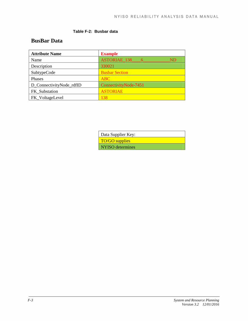
N Y I S O R E L I A B I L I T Y A N A L Y S I S D A T A M A N U A L
F-3 System and Resource Planning Version 3.2 12/01/2016
Table F-2: Busbar data
BusBar Data Attribute Name Example Name ASTORIAE_138____6____________ND Description 330021 SubtypeCode Busbar Section Phases ABC D_ConnectivityNode_rdfID ConnectivityNode-7451 FK_Substation ASTORIAE FK_VoltageLevel 138 Data Supplier Key: TO/GO supplies NYISO determines

N Y I S O R E L I A B I L I T Y A N A L Y S I S D A T A M A N U A L
System and Resource Planning F-4 Version 3.2 12/01/2016
Table F-3: Synchronous Machine data
Synchronous Machine Data Attribute Name Example name ARTHUR_KILL_2 description 23512 SubtypeCode Generator phases ABC FK_Substation FRESHKLS FK_VoltageLevel 20 FK_AggGeneratingUnit FK_GeneratingUnit ARTHUR_KILL_2 FK_Measurement Measurement-BB-KV4 maximumMVAR 312 minimumMVAR -186 rDemandAccOutputLimitHigh 350 rDemandAccOutputLimitLow 0 Data Supplier Key: TO/GO supplies NYISO determines
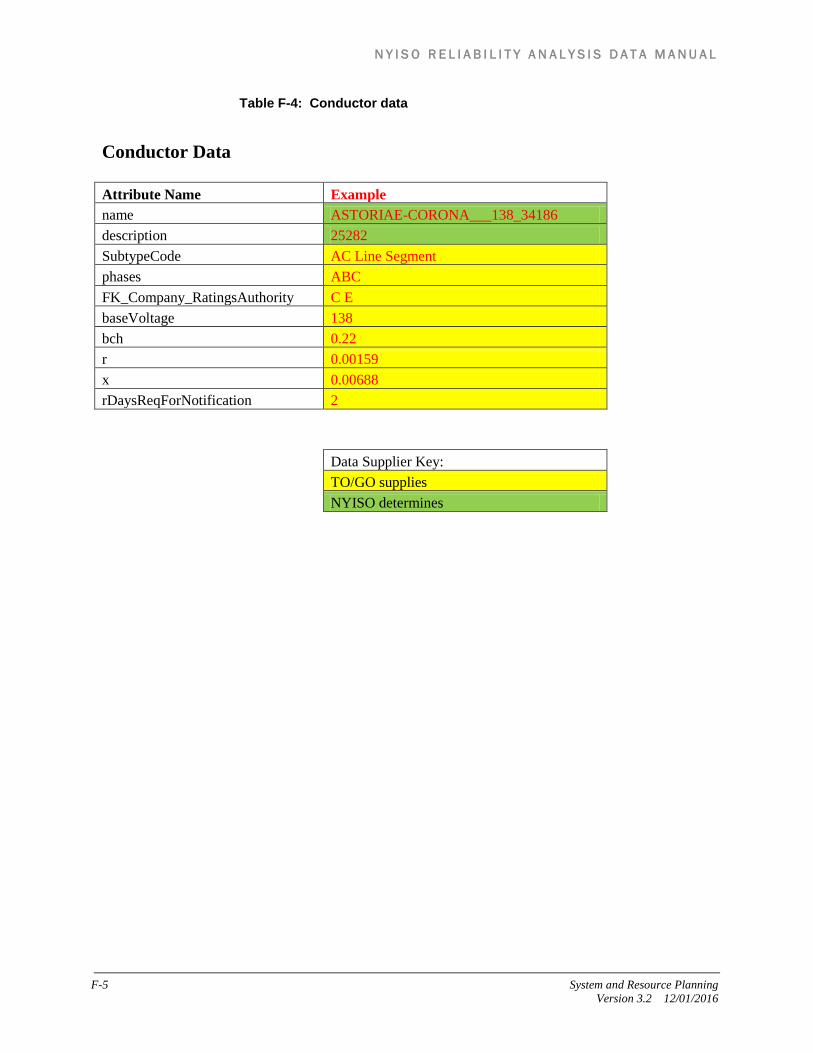
N Y I S O R E L I A B I L I T Y A N A L Y S I S D A T A M A N U A L
F-5 System and Resource Planning Version 3.2 12/01/2016
Table F-4: Conductor data
Conductor Data Attribute Name Example name ASTORIAE-CORONA___138_34186 description 25282 SubtypeCode AC Line Segment phases ABC FK_Company_RatingsAuthority C E baseVoltage 138 bch 0.22 r 0.00159 x 0.00688 rDaysReqForNotification 2 Data Supplier Key: TO/GO supplies NYISO determines

N Y I S O R E L I A B I L I T Y A N A L Y S I S D A T A M A N U A L
System and Resource Planning F-6 Version 3.2 12/01/2016
Table F-5: Transformer data
Transformer Data Attribute Name Example name ASTORIA3_138_20__BK 3N description 70124 SubtypeCode Two Winding phases ABC FK_Substation ASTORIA3 transformer Type Fix rPhaseShiftController No rTapData Yes SubtypeCode TransformerWinding VoltagLevelHighSide 138 VoltagLevelLowSide 20 bch 0 r 0 x 0.0644 highStep 33 lowStep 1 neutralAngle 0 newtralKV 125.44 newtralStep 1 normalStep 17 stepPhaseShifterIncremental 0.775 Data Supplier Key: TO/GO supplies NYISO determines

N Y I S O R E L I A B I L I T Y A N A L Y S I S D A T A M A N U A L
F-7 System and Resource Planning Version 3.2 12/01/2016
Table F-6: Energy Consumer data
Energy Consumer Data (Load) Attribute Name Example name ASTORIAE_138KV_NQ_38Q11 description 335517 SubtypeCode Equivalent Load phases ABC FK_Substation ASTORIAE FK_VoltageLevel 138 conformingLoadFlag Yes pFixed 70.30000305 qFixed 18.5 Data Supplier Key: TO/GO supplies NYISO determines

N Y I S O R E L I A B I L I T Y A N A L Y S I S D A T A M A N U A L
System and Resource Planning F-8 Version 3.2 12/01/2016
Table F-7: Compensator data
Compensator Data (Shunts) Attribute Name Example name EFISHKIL_345KV_CAP_CAP _1 description 31334 SubtypeCode Shunt Capacitor phases ABC FK_Substation EFISHKIL FK_VoltageLevel 345 FK_Measurement Measurement-BB-KV1016 Compensator Type Shunt nominalMVAR 135 mVARperSection 135 MaximumSections 1 nominalKV 345 Data Supplier Key: TO/GO supplies NYISO determines

N Y I S O R E L I A B I L I T Y A N A L Y S I S D A T A M A N U A L
F-9 System and Resource Planning Version 3.2 12/01/2016
Table F-8: Switch data
Switch Data Attribute Name Example name ASTORIAE_138KV_F6E description 14755 SubtypeCode Breaker phases ABC FK_Substation ASTORIAE FK_VoltageLevel 138 Data Supplier Key: TO/GO supplies NYISO determines

N Y I S O R E L I A B I L I T Y A N A L Y S I S D A T A M A N U A L
System and Resource Planning F-10 Version 3.2 12/01/2016
Table F-9: Static Var Compensator data
Static Var Compensator Data Attribute Name Example name LEEDS____345_LEEDS SVC description 31327 SubtypeCode Static Var Compensator phases ABC FK_Substation LEEDS FK_VoltageLevel 345 FK_Measurement Measurement-BB-KV3528 capacitiveRating 270 inductiveRating -300 rDaysReqForNotification 30 Data Supplier Key: TO/GO supplies NYISO determines

N Y I S O R E L I A B I L I T Y A N A L Y S I S D A T A M A N U A L
F-11 System and Resource Planning Version 3.2 12/01/2016
Table F-10: Facility Ratings Update data
Facility Rating Data Attribute Name Example equipName ROSETON_-EFISHKIL_345_305 description 25108 company CH equipType LN lineID 305 powerfactor 100 voltageLevel 345 summerNOR* 1936 summerNORCode D - Disconnect summerLTE* 2743 summerLTECode D - Disconnect summerSTE* 3407 summerSTECode A - Conductor winterNOR* 2528 winterNORCode D - Disconnect winterLTE* 3191 winterLTECode D - Disconnect winterSTE* 3585 winterSTECode D - Disconnect Data Supplier Key: TO/GO supplies NYISO determines
* Facility ratings are provided in megawatts.