regenerative storm conveyance design review checklist · final draft regenerative storm conveyance...
TRANSCRIPT

FINAL DRAFT Regenerative Storm Conveyance Design Review Checklist
__________________________________________________________________________________________________________________________________________________________________________________________
U.S. Fish and Wildlife Service Stream Mechanics
Regenerative Storm Conveyance Design Review
Checklist
CBFO-S15-04
February 2015

FINAL DRAFT Regenerative Storm Conveyance Design Review Checklist
__________________________________________________________________________________________________________________________________________________________________________________________
U.S. Fish and Wildlife Service Stream Mechanics
Prepared By:
U. S. Fish and Wildlife Services
Richard R. Starr Stream Mechanics, PLLC
William A. Harman, PG February 2015 Appropriate Citation: Starr, R., W. Harman. 2015. Regenerative Storm Conveyance Design Review Checklist Version 3. U.S. Fish and Wildlife Service, Chesapeake Bay Field Office, Annapolis, MD. CBFO-S15-04. Funding for the Regenerative Storm Conveyance Design Review Checklist was provided by the Maryland Department of Environment, Maryland State Highway Administration and the U.S. Fish and Wildlife Service. The information, findings and conclusions in this document are those of the authors and do not necessarily represent the views of the U.S. Fish and Wildlife Service.

FINAL DRAFT Regenerative Storm Conveyance Design Review Checklist
__________________________________________________________________________________________________________________________________________________________________________________________
U.S. Fish and Wildlife Service Stream Mechanics
TABLE OF CONTENTS
Introduction ......................................................................................................................................... 1
Checklist Structure ............................................................................................................................. 2
Regenerative Storm Conveyance Design Approach ........................................................................ 3
1.0 Basemapping and Hydraulic Assessment .................................................................................. 3
1.1 Basemapping ........................................................................................................................... 3
1.2 Hydraulic Assessment ............................................................................................................. 4
2.0 Preliminary Design ...................................................................................................................... 5
2.1 Sediment Transport ................................................................................................................ 5
2.2 Goals and Restoration Potential ............................................................................................ 9
2.3 Design Criteria ...................................................................................................................... 10
2.4 Conceptual Design ................................................................................................................ 12
3.0 Final Design ................................................................................................................................ 14
3.1 RSC Restoration Design ....................................................................................................... 14
3.2 In-Stream Structures ............................................................................................................ 18
3.3 Vegetation Design.................................................................................................................. 21
4.0 Overall Design Review .............................................................................................................. 21
5.0 References .................................................................................................................................. 23 List of Figures & Tables
Figure 1 Review Checklist Structure
Figure 2 Example Stream Power Versus Stage and Discharge.
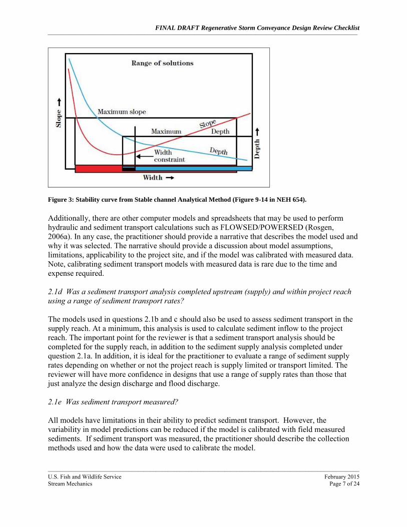
Figure 3 Stability curve from Stable channel Analytical Method (Figure 9-14 in NEH 654).
Figure 4 A typical riffle and pool cross section showing key measurements.
Figure 5 Proposed cross section overlaid with the existing ground. These are often shown on a set interval throughout the length of the project reach and are used by the contractor to excavate the channel and floodplain (if needed).
Figure 6 Example Longitudinal Profile
Table 1 Guidance for selecting in-stream structures to provide bank protection.
Table 2 Guidance for selecting bioengineering practices for bank protection.

FINAL DRAFT Regenerative Storm Conveyance Design Review Checklist
__________________________________________________________________________________________________________________________________________________________________________________________
U.S. Fish and Wildlife Service Stream Mechanics
List of Appendices
Appendix A Regenerative Storm Conveyance Design Review Checklist
Appendix B Stream Classification Key
Appendix C Simon Channel Evolution Model; Channel Evolution by Stream Type
Appendix D Regional Curves and Manning’s Equation
Appendix E Design Goals and Objectives
Appendix F In-stream Structures
Appendix G Additional References
FINAL DRAFT Regenerative Storm Conveyance Design Review Checklist
__________________________________________________________________________________________________________________________________________________________________________________________
________________________________________________________________________________________________________
U.S. Fish and Wildlife Service February 2015 Stream Mechanics Page 1 of 24
Introduction The U.S. Fish and Wildlife Service – Chesapeake Bay Field Office (Service) has entered into a partnership with the Maryland Department of Environment (MDE), and Maryland State Highway Administration (SHA) to update the Natural Channel Design Review Checklist (NCD V3) and develop three new design checklists. The three new checklists include: analytical design (AD), valley restoration design (VRD), and regenerative storm conveyance design (RSCD). The development of new checklists is based on the request from MDE to provide review checklists for commonly used design approaches in Maryland. A new, stand-alone checklist manual has been created for each checklist; therefore, this document only includes the Analytical Design Review Checklist. While there are a number of standard questions in each checklist, the decision to create individual stand-alone documents was based on ease of use. By creating individual documents for each checklist, users will not be required to refer to other checklist documents for guidance where standard questions may have been initially addressed. Each checklist is provided in Appendix A and provides questions about important items to consider when reviewing stream restoration designs. The Checklist is intended to provide the reviewer with a method for determining if a project design contains an appropriate level of information for identifying major design shortcomings. However, no review can ensure project success. The final responsibility for a successful project lies with the project owner, designer and contractor. Below is a list of other items that should be considered when using the checklist:
It is highly recommended that the reviewer conduct a site visit to determine if the assessment and design accurately document what is observed at the site. The reviewer should also look for additional constraints (as well as restoration opportunities) that might have been left out of the report
It is important to note that designers may not always complete every item listed in this Checklist. That is acceptable, especially for experienced designers. If the designer is submitting the Checklist as a permit requirement, they should simply state why they did not need to address that issue.
While a review checklist has been available for the NCD approach since 2008, the checklists for the other design approaches are new. Therefore, these checklists are being released as final drafts. The Service requests feedback from users for one year. The Service will then revisit and potentially revise the checklists based on feedback.

FINAL DRAFT Regenerative Storm Conveyance Design Review Checklist
__________________________________________________________________________________________________________________________________________________________________________________________
________________________________________________________________________________________________________
U.S. Fish and Wildlife Service February 2015 Stream Mechanics Page 2 of 24
Checklist Structure All four checklists have the same structure. There are four columns for most questions, which include Submitted, Acceptable, Page Number and Comments (Figure 1). The reviewer answers “yes”, “no” or “partially” for Submitted and Acceptable and provides a reason/explanation for Comments. A column is also provided to cite the page number where the information is discussed in the report. This format is straightforward for some questions, like “1.1a - Does the project include basemapping?” Under the Submitted column, the reviewer would respond with “yes” if the designer submitted a basemap. If the basemap was inadequate, the reviewer would respond with “no” under the Acceptable column and then describe why under Comments.
Submitted
(Y/N/P)
Acceptable
(Y/N/P)Page # CommentsItem
1.0 Basemapping and Hydraulic Assessment
1.2 Hydraulic Assessment
1.2b Was a hydraulic assessment completed?
1.2c Was stream velocity, shear stress and
stream power shown in relation to stage and
discharge?
1.1 Basemapping
1.1a Does the project include basemapping?
1.2a Was the project drainage area provided?
Figure 1: Review Checklist Structure
Other questions are not as straightforward in terms of fitting the checklist structure. For example, under Section 3.2 In-Stream Structures, question 3.2d asks, “Will the in-stream structures provide the intended stability?” For questions that seem to warrant a direct answer, the reviewer should still follow the two-step process: (1) Determine if the designer Submitted information that answers this question, even if it is more implicit in the report than explicit; (2) Decide if the information is Acceptable and Comment on their reason. Finally, there are places in the checklist where the reviewer can provide overall comments and impressions about the assessment and design. These sections do not require a “yes” or “no” for Submitted or Acceptable. This document follows the order of the checklist (Appendix A) and includes the following sections: Basemapping, Preliminary Design, Final Design and Overall Design Review. Since the checklist is primarily for natural channel designs, the Rosgen steam classification system and Priority Levels of Restoring Incised Channels are referenced throughout the test. Therefore, the classification key and a description of the priority levels of restoration are provided in Appendix B. Reviewers who are not familiar with the classification key or the priority levels may want to read this appendix before using the checklist.
FINAL DRAFT Regenerative Storm Conveyance Design Review Checklist
__________________________________________________________________________________________________________________________________________________________________________________________
________________________________________________________________________________________________________
U.S. Fish and Wildlife Service February 2015 Stream Mechanics Page 3 of 24
Regenerative Storm Conveyance Design Approach
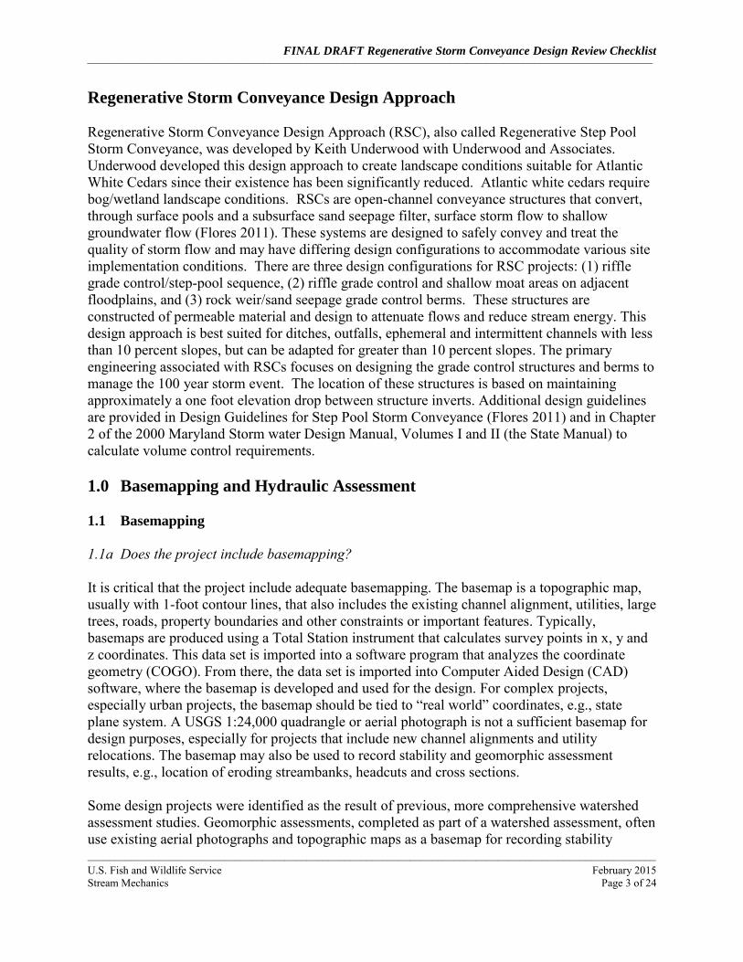
Regenerative Storm Conveyance Design Approach (RSC), also called Regenerative Step Pool Storm Conveyance, was developed by Keith Underwood with Underwood and Associates. Underwood developed this design approach to create landscape conditions suitable for Atlantic White Cedars since their existence has been significantly reduced. Atlantic white cedars require bog/wetland landscape conditions. RSCs are open-channel conveyance structures that convert, through surface pools and a subsurface sand seepage filter, surface storm flow to shallow groundwater flow (Flores 2011). These systems are designed to safely convey and treat the quality of storm flow and may have differing design configurations to accommodate various site implementation conditions. There are three design configurations for RSC projects: (1) riffle grade control/step-pool sequence, (2) riffle grade control and shallow moat areas on adjacent floodplains, and (3) rock weir/sand seepage grade control berms. These structures are constructed of permeable material and design to attenuate flows and reduce stream energy. This design approach is best suited for ditches, outfalls, ephemeral and intermittent channels with less than 10 percent slopes, but can be adapted for greater than 10 percent slopes. The primary engineering associated with RSCs focuses on designing the grade control structures and berms to manage the 100 year storm event. The location of these structures is based on maintaining approximately a one foot elevation drop between structure inverts. Additional design guidelines are provided in Design Guidelines for Step Pool Storm Conveyance (Flores 2011) and in Chapter 2 of the 2000 Maryland Storm water Design Manual, Volumes I and II (the State Manual) to calculate volume control requirements. 1.0 Basemapping and Hydraulic Assessment 1.1 Basemapping
1.1a Does the project include basemapping? It is critical that the project include adequate basemapping. The basemap is a topographic map, usually with 1-foot contour lines, that also includes the existing channel alignment, utilities, large trees, roads, property boundaries and other constraints or important features. Typically, basemaps are produced using a Total Station instrument that calculates survey points in x, y and z coordinates. This data set is imported into a software program that analyzes the coordinate geometry (COGO). From there, the data set is imported into Computer Aided Design (CAD) software, where the basemap is developed and used for the design. For complex projects, especially urban projects, the basemap should be tied to “real world” coordinates, e.g., state plane system. A USGS 1:24,000 quadrangle or aerial photograph is not a sufficient basemap for design purposes, especially for projects that include new channel alignments and utility relocations. The basemap may also be used to record stability and geomorphic assessment results, e.g., location of eroding streambanks, headcuts and cross sections. Some design projects were identified as the result of previous, more comprehensive watershed assessment studies. Geomorphic assessments, completed as part of a watershed assessment, often use existing aerial photographs and topographic maps as a basemap for recording stability

FINAL DRAFT Regenerative Storm Conveyance Design Review Checklist
__________________________________________________________________________________________________________________________________________________________________________________________
________________________________________________________________________________________________________
U.S. Fish and Wildlife Service February 2015 Stream Mechanics Page 4 of 24
problems. This is a useful technique for the assessment and for developing concept designs, but should not be used as the basemap for the final design that will be used by contractors to build the project. 1.2 Hydraulic Assessment
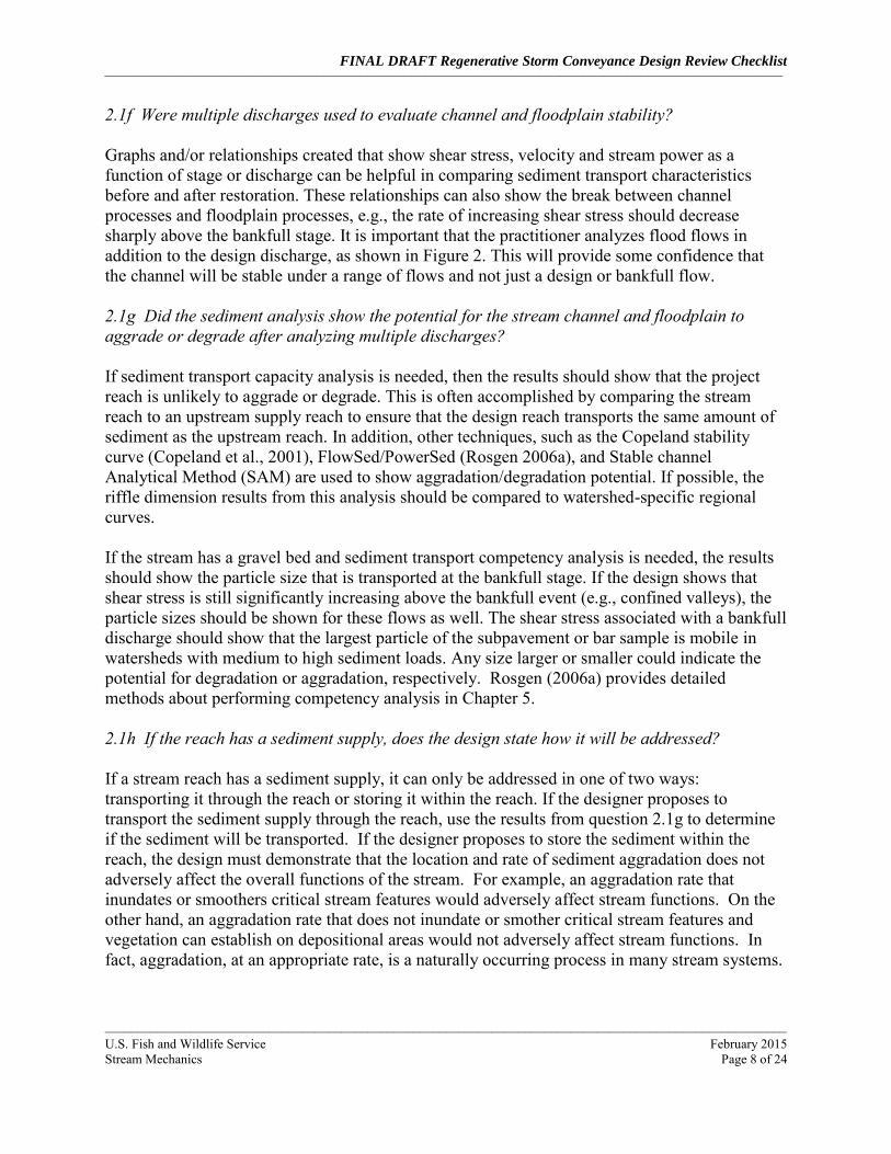
1.2a Was the project drainage area provided? This is an important question because many of the hydrologic, hydraulic and geomorphic relationships are expressed as functions of drainage area. For example, regional hydraulic geometry curves (regional curves) are log-log plots comparing channel dimensions (e.g., bankfull width, mean depth and cross-sectional area) versus drainage area. Drainage area also significantly influences water yield, specifically how much and how quickly, and water yield is required for most hydrologic and hydraulic models. It is impossible to review this and other design elements without knowing the drainage area. Drainage area is typically provided in square miles for natural channel designs. 1.2b Was a hydraulic assessment completed? A hydraulic assessment can be used to determine stream power and most stream restoration projects will include some type of hydraulic assessment. The level of assessment will vary based on the complexity of the project. For example, urban projects in FEMA-regulated floodplains will have more complex assessments than simple bank stabilization projects in rural environments. Copeland et al. (2001) provides a detailed overview of hydraulic design methods for stream restoration projects. 1.2c Was stream channel velocity, shear stress and stream power shown in relation to stage and discharge? The design report should include a discussion about flow dynamics. The primary purpose is to determine the erosive power of channel and flood flows. This is often shown through plots or tables of stream velocity, shear stress and/or stream power versus stage or discharge (Figure 2). Flow dynamics should, at a minimum, be assessed for the bankfull discharge plus flood flows. Projects that include fish passage or other low-flow velocity requirements will require base-flow assessments.
Little Tuscarora Stream Restoration
Flood Event
Discharge Stage Velocity Shear Stress Stream Power
(cfs) (ft) (ft/s) (lb/sq ft) (lb/ft s)
BKF 116 296.25 3.86 0.63 2.42
2 Year 197 296.67 5.05 1.02 5.16
10 Year 540 297.83 6.42 1.44 9.27
100 Year 1292 299 6.09 1.15 6.99
Figure 2: Example Stream Power Versus Stage and Discharge.
FINAL DRAFT Regenerative Storm Conveyance Design Review Checklist
__________________________________________________________________________________________________________________________________________________________________________________________
________________________________________________________________________________________________________
U.S. Fish and Wildlife Service February 2015 Stream Mechanics Page 5 of 24
2.0 Preliminary Design The preliminary design uses data from the hydraulic analysis, watershed and stream assessments (accomplished as a previous effort) and sediment transport analysis to create project-specific design goals and restoration potential. From there, the design criteria and a conceptual design can be developed. This information should generally be completed and presented to the stakeholders before proceeding to final design. 2.1 Sediment Transport
2.1a Did the sediment transport analysis include an evaluation of sediment supply (i.e., sediment supply amount and source(s))? The reviewer should look for two things. First, the practitioner should perform some type of broad-level sediment supply analysis. This should include investigations of upstream bank erosion through stream walks, windshield surveys, aerial photo analysis, etc. Other sediment sources should also be identified, including cropland erosion, gravel roads, hillslopes, etc. These investigations may include a combination of quantitative and qualitative measures to provide an overall assessment of sediment supply. The reviewer (and practitioner) needs to know if the project reach receives high, medium, or low levels of sediment supply. Projects with very low sediment supply have more design freedom than streams with medium to high levels of sediment supply. In other words, project reaches that must transport sediment have a greater risk of future instability if errors are made in designing channel dimension, pattern, and profile. Second, once the broad-level sediment supply assessment is completed, a quantitative analysis of the upstream sediment supply reach is performed. This review is completed under question 2.1d: Was a sediment transport analysis completed for the supply reach and project reach? 2.1b Was a model used to calculate sediment transport described, including assumptions and applicability to project reach conditions? Most, but not all, projects will require some form of sediment transport analysis. Sediment transport analysis is one of the more complex components of a stream design. These analyses usually address questions about the ability of the stream to transport sediment particles of a certain size (competency) and load (capacity). There are a variety of references available to learn more about sediment transport. Two include Rosgen (2006a) in Chapter 2 and Wilcock et al., (2009). If sediment transport analyses are required, it is important to know why one type of sediment transport analysis was selected over another. The type and distribution of the bed material governs the complexity of the analyses, i.e., bed material composed of all sand requires fewer analyses than cobble, gravel and sand mixtures. An important question to ask includes: Were sediment transport competency and capacity calculations completed? If not, the practitioner should provide a reason. If so, the practitioner should provide a narrative that describes the model used and why it was selected. The narrative should provide a discussion about model assumptions, limitations, applicability to the project site, and if the model was
FINAL DRAFT Regenerative Storm Conveyance Design Review Checklist
__________________________________________________________________________________________________________________________________________________________________________________________
________________________________________________________________________________________________________
U.S. Fish and Wildlife Service February 2015 Stream Mechanics Page 6 of 24
calibrated with measured data. Note, calibrating sediment transport models with measured data is rare due to the time and expense required. Some projects do not require sediment transport modeling, e.g., projects with low sediment supply from the upstream watershed. Examples include low-gradient coastal plain streams and highly urbanized streams. However, urban streams may require an analysis to design constructed riffles that will not erode. Projects located in bed load transport reaches with upstream sources of sediment should include sediment transport analysis. Results of the sediment supply analysis completed under question 2.1a will help in determining the appropriate level of sediment transport analysis. 2.1c Were SAM, HEC-RAS, or other tools used to determine stable channel and floodplain dimensions based on sediment transport and/or resistance to shear stress A practitioner may use multiple methods to determine the channel dimension, such as the modeling results and watershed-specific regional curves. They may use several methods and look for “converging lines of evidence,” which is considered “best practice.” It is important for the reviewer to understand how the practitioner calculated the channel dimension and slope in this process. If the practitioner did not compare the modeling results with bankfull regional curves, and regional curves are available, the reviewer should make this comparison to determine if the results are acceptable. Hydraulic and sediment transport modeling are performed together in order to predict channel dimension and slope. Typically, the U.S. Army Corps of Engineers, Stable channel Analytical Method (USACE-SAM) is used for this purpose (Copeland et al., 2001). This routine is now part of HEC-RAS, making it easier to link the hydraulic analysis with the sediment transport analysis. The model calculates a range of stable channel dimensions given a design discharge and sediment concentration. An example from the NEH 654 is shown below in Figure 3. While RSC projects that use sand seepage berms do not typically have a “traditional” single thread channel, this model should still be able to show if aggradation could occur.
FINAL DRAFT Regenerative Storm Conveyance Design Review Checklist
__________________________________________________________________________________________________________________________________________________________________________________________
________________________________________________________________________________________________________
U.S. Fish and Wildlife Service February 2015 Stream Mechanics Page 7 of 24
Figure 3: Stability curve from Stable channel Analytical Method (Figure 9-14 in NEH 654). Additionally, there are other computer models and spreadsheets that may be used to perform hydraulic and sediment transport calculations such as FLOWSED/POWERSED (Rosgen, 2006a). In any case, the practitioner should provide a narrative that describes the model used and why it was selected. The narrative should provide a discussion about model assumptions, limitations, applicability to the project site, and if the model was calibrated with measured data. Note, calibrating sediment transport models with measured data is rare due to the time and expense required. 2.1d Was a sediment transport analysis completed upstream (supply) and within project reach using a range of sediment transport rates? The models used in questions 2.1b and c should also be used to assess sediment transport in the supply reach. At a minimum, this analysis is used to calculate sediment inflow to the project reach. The important point for the reviewer is that a sediment transport analysis should be completed for the supply reach, in addition to the sediment supply analysis completed under question 2.1a. In addition, it is ideal for the practitioner to evaluate a range of sediment supply rates depending on whether or not the project reach is supply limited or transport limited. The reviewer will have more confidence in designs that use a range of supply rates than those that just analyze the design discharge and flood discharge. 2.1e Was sediment transport measured? All models have limitations in their ability to predict sediment transport. However, the variability in model predictions can be reduced if the model is calibrated with field measured sediments. If sediment transport was measured, the practitioner should describe the collection methods used and how the data were used to calibrate the model.
FINAL DRAFT Regenerative Storm Conveyance Design Review Checklist
__________________________________________________________________________________________________________________________________________________________________________________________
________________________________________________________________________________________________________
U.S. Fish and Wildlife Service February 2015 Stream Mechanics Page 8 of 24
2.1f Were multiple discharges used to evaluate channel and floodplain stability? Graphs and/or relationships created that show shear stress, velocity and stream power as a function of stage or discharge can be helpful in comparing sediment transport characteristics before and after restoration. These relationships can also show the break between channel processes and floodplain processes, e.g., the rate of increasing shear stress should decrease sharply above the bankfull stage. It is important that the practitioner analyzes flood flows in addition to the design discharge, as shown in Figure 2. This will provide some confidence that the channel will be stable under a range of flows and not just a design or bankfull flow. 2.1g Did the sediment analysis show the potential for the stream channel and floodplain to aggrade or degrade after analyzing multiple discharges? If sediment transport capacity analysis is needed, then the results should show that the project reach is unlikely to aggrade or degrade. This is often accomplished by comparing the stream reach to an upstream supply reach to ensure that the design reach transports the same amount of sediment as the upstream reach. In addition, other techniques, such as the Copeland stability curve (Copeland et al., 2001), FlowSed/PowerSed (Rosgen 2006a), and Stable channel Analytical Method (SAM) are used to show aggradation/degradation potential. If possible, the riffle dimension results from this analysis should be compared to watershed-specific regional curves. If the stream has a gravel bed and sediment transport competency analysis is needed, the results should show the particle size that is transported at the bankfull stage. If the design shows that shear stress is still significantly increasing above the bankfull event (e.g., confined valleys), the particle sizes should be shown for these flows as well. The shear stress associated with a bankfull discharge should show that the largest particle of the subpavement or bar sample is mobile in watersheds with medium to high sediment loads. Any size larger or smaller could indicate the potential for degradation or aggradation, respectively. Rosgen (2006a) provides detailed methods about performing competency analysis in Chapter 5. 2.1h If the reach has a sediment supply, does the design state how it will be addressed? If a stream reach has a sediment supply, it can only be addressed in one of two ways: transporting it through the reach or storing it within the reach. If the designer proposes to transport the sediment supply through the reach, use the results from question 2.1g to determine if the sediment will be transported. If the designer proposes to store the sediment within the reach, the design must demonstrate that the location and rate of sediment aggradation does not adversely affect the overall functions of the stream. For example, an aggradation rate that inundates or smoothers critical stream features would adversely affect stream functions. On the other hand, an aggradation rate that does not inundate or smother critical stream features and vegetation can establish on depositional areas would not adversely affect stream functions. In fact, aggradation, at an appropriate rate, is a naturally occurring process in many stream systems.
FINAL DRAFT Regenerative Storm Conveyance Design Review Checklist
__________________________________________________________________________________________________________________________________________________________________________________________
________________________________________________________________________________________________________
U.S. Fish and Wildlife Service February 2015 Stream Mechanics Page 9 of 24
2.2 Goals and Restoration Potential
2.2a Is the proposed design approach appropriate given the size of the DA? While Flores 2011 does not provide specific drainage area thresholds for RSC projects, it does state that RSC projects are best suited for ditches, outfalls, ephemeral and intermittent channels. 2.2b Does the project have clear goals and measurable objectives? Every stream restoration project, large or small, should have clearly stated goals and objectives. The goals should answer the question, “What is the purpose of this project?” Goals may be as specific as stabilizing an eroding streambank that is threatening a road, or as broad as improving stream functions to match reference reach conditions. It is common to see a goal that reads, “The purpose of this project is to restore channel dimension, pattern and profile.” The problem with this goal is that it fails to state why there is a need to change the channel geometry. The goal should address a problem, which could be a stability issue, a functional issue or both. Examples of goals based on improving stream functions are provided in Appendix E. The Stream Functions Pyramid is also provided in Appendix E (Harman et al., 2012). The Stream Functions Pyramid can be used as an aid in developing goals and objectives. The goals should relate to the function-based parameters and the objectives should relate to the measurement methods and performance standards. The question about project goals and objectives is provided after the geomorphic and hydraulic assessment because this information is needed to determine functional improvement (lift). In other words, once the stability problem and/or functional impairment are understood, clear goals and objectives can be articulated. This will lead to designs that focus on solving a functional problem rather than simply addressing dimension, pattern and profile. It will also help the reviewer understand why the project is being proposed. 2.2c Was the restoration potential based on the assessment data provided? Based on the watershed, hydraulic and geomorphic assessment results, the restoration potential should be provided. The restoration potential should state the highest level of restoration attainable given health of the upstream watershed, results from the reach assessment, and site constraints (Harman et al., 2012).. For example, if a stream has been channelized and relocated to the edge of the valley to increase agricultural production, but the landowner is willing to take the land out of production, the restoration potential may be to reconstruct a meandering channel through the original floodplain. The entire floodplain may be converted into a bottomland hardwood forest with riparian wetlands. . If the upstream watershed is mostly forested and healthy, than the restoration potential is level 5 on the Stream Functions Pyramid. This means that the project has a strong potential for restoring biological functions back to a reference condition. If the same site has an urban watershed, the restoration potential is Level 3, meaning that a stable channel can be created, but it may not support biology at a reference condition (Harman et al., 2012).
FINAL DRAFT Regenerative Storm Conveyance Design Review Checklist
__________________________________________________________________________________________________________________________________________________________________________________________
________________________________________________________________________________________________________
U.S. Fish and Wildlife Service February 2015 Stream Mechanics Page 10 of 24
2.2d Was a restoration strategy developed and explained based on the restoration potential? The restoration strategy explains how the goals and objectives are going to be achieved based on the restoration potential. A typical restoration strategy for RSC projects involve construction of open-channel conveyance structures that convert, through surface pools and a subsurface sand seepage filter, surface storm flow to shallow groundwater flow. The strategy may then more specifically address function-based goals and objectives, e.g., bed form diversity and complexity to support a certain species of interest, or increased floodplain connectivity (lower slope and velocity) to encourage development of floodplain wetlands.
2.3 Design Criteria
2.3a Were design criteria provided and explained? The development of design criteria is one of the most important tasks in a channel design. Design criteria provide the numerical guidelines for designing channel dimension, pattern and profile. These criteria can come from a number of sources such as from reference reach surveys. If possible, reference reach survey results (ratios) should be compared to other methods, including analytical models (Copeland et al., 2001), regime equations (Hey, 2006) and results from project monitoring and evaluation. Lessons learned from past project evaluations should play a major role in making final design criteria decisions 2.3b Was the method used to determine riffle and/or weir widths and depths described? If riffle and/or weir width and depth calculations were completed, it is important that the methods used to complete the calculations are described. Width and depth calculations range from simple equations to intensive hydrology and hydraulic models. Data collection, data sources and methods used to determine riffle and/or weir widths and depths should be described. 2.3c Were fluvial geomorphic principles used to select the dependent variable, e.g., width? The width and depth are sized by analyzing boundary shear stress and critical shear stress in conjunction with proposed substrate materials. Most RSC projects are design based on the 100year storm event. Therefore, the sizing of the riffle, weir and/or cascade should accommodate the shear stresses associated with the 100 year storm event. 2.3d Were hydrology and hydraulic models used to determine the riffle and/or weir design width, depth and slope? If hydrology and hydraulic models were used to determine the riffle and/or weir width, depth and slope, it is important to ensure that the data used in the models accurately reflect the watershed and site conditions. The accuracy of the data will influence the appropriate sizing of riffles and/or weirs to ensure stability for the design flows. Critical data includes the following: precipitation and runoff data, basin slope, time of concentration, flow path, and existing land use.

FINAL DRAFT Regenerative Storm Conveyance Design Review Checklist
__________________________________________________________________________________________________________________________________________________________________________________________
________________________________________________________________________________________________________
U.S. Fish and Wildlife Service February 2015 Stream Mechanics Page 11 of 24
2.3e Was the method used to determine cascade height (if part of design) described? The correct cascade height is critical in dissipating stream energy. If too low, stream energy may not be appropriately dissipated resulting in increased energy being transferred downstream and potentially causing erosion. If too high, stream energy may be increased causing pool scour and potentially undermining of the cascade footers and ultimately structure failure. Data collection, data sources and methods used to determine cascade heights should be described. 2.3f Was design criteria for sand seepage berms (if part of design) provided? Appropriate berm dimensions and materials are critical to ensure stability as well as meeting project goals and objectives (i.e., specifically water quality). The berm dimensions should be sized for the proposed design flows and incorporate the riffle and/or weir dimensions. The materials should be based on the goals and objectives of the project but also consider stability issues such as piping. 2.3g Were hydrology and hydraulic models used to determine and test stability of berm heights and widths (if part of design)? Hydrology and hydraulic models should be used to show that the berm heights, along with the riffle and/or weir dimensions will pass the design flows without being over topped. Since most berms consist of sand and other easily erodible materials, any flows that over top the berms could result in erosion of the berm and potential berm failure, especially until vegetation establishes on the berm. 2.3h Were the methods used to design the plan form and bed forms described? Approaches for designing plan form diversity are not specifically described in the RSC Approach. However, pool depths and pool-to-pool spacing are defined. The spacing of pools is based on maintaining approximately a one foot elevation drop between structure inverts. And the pool depths are based on scour calculations. The concept plan should demonstrate that appropriate pool spacing and depths are proposed to prevent excessive scouring and degradation. 2.3i Was the design discharge compared to bankfull discharge from appropriate regional curve? The RSC Restoration Approach does not include an analysis to estimate the bankfull discharge or dimensions. However, regulators may want to see a comparison of the baseflow channel dimensions and discharge with a local bankfull regional curve. 2.3j Were any other design criteria provided and explained? This question simply acknowledges that each project reach is unique and therefore new or varied design criteria may be used.
FINAL DRAFT Regenerative Storm Conveyance Design Review Checklist
__________________________________________________________________________________________________________________________________________________________________________________________
________________________________________________________________________________________________________
U.S. Fish and Wildlife Service February 2015 Stream Mechanics Page 12 of 24
2.3k Are the design criteria appropriate, given the site conditions and restoration potential? Is the proposed stream representative of a stream that would be associated with the watershed characteristics and valley type? Watershed characteristics and valley type significantly influence stream channel characteristics. For example high gradient, culluvial valleys typical have vertically meandering, steep-pool dominated stream systems. Whereas low gradient, alluvial valleys typically have laterally meandering, riffle-pool sequence dominated stream systems. If the proposed stream design is not typical for the proposed site, did the designer state why a different stream type is proposed. 2.4 Conceptual Design
2.4a Was the conceptual channel alignment provided and developed within the design width and slope range and follow the natural drainage path of the valley? The most important part of the preliminary design is that it shows the proposed channel alignment. For RSC projects, it is important that the channel alignment follow the natural drainage path of the valley. Additionally the location of the riffles, weirs, step pools and/or cascades will influence sediment transport/deposition, if there is a sediment load, and should be placed to ensure the direction of flows pass through the structures. The reviewer should verify that the proposed alignment is within the design criteria. 2.4b Were typical riffle, weir, and floodplain cross sections provided and developed within the design width, depth and slope ranges? Typical riffle, weir and floodplain cross sections should be provided. The typical cross sections should show, at a minimum, the top width, bottom width, maximum depth, mean depth and bank slopes. The reviewer should make certain that the preliminary typical cross sections meet the design criteria. 2.4c Were typical cascade drawings provided and developed within the design criteria? Typical cascade drawing should be provided. The typical cascade drawing should show, at a minimum, the top width, bottom width, maximum depth, mean depth and bank slopes. The reviewer should make certain that the preliminary typical cascade drawings meet the design criteria. 2.4d Were typical berm height and width cross sections and profiles provided and within the design criteria? Typical berm height and width cross sections and profiles should be provided. The typical berm height and width cross sections should show, at a minimum, the top width, bottom width, and bank slopes. The typical profile should show, at a minimum, the height and width of riffle, weir and/or cascade tops, pool depths and lengths, and floodplain connection. The reviewer should make certain that the preliminary typical berm dimensions meet the design criteria.
FINAL DRAFT Regenerative Storm Conveyance Design Review Checklist __________________________________________________________________________________________________________________________________________________________________________________________
________________________________________________________________________________________________________
U.S. Fish and Wildlife Service February 2015 Stream Mechanics Page 13 of 24
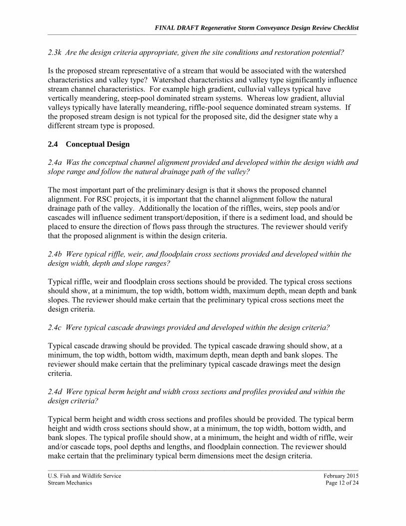
2.4e Were typical drawings of in-stream and floodplain structures provided and their use and location explained? Typical channel and floodplain cross sections should be provided. The typical cross sections should show, at a minimum, the stream channel top width, bottom width, maximum depth, mean depth and bank slopes and floodplain widths (Figure 4). As part of the review, the reviewer should make certain that the preliminary in-stream and floodplain structures meet the design criteria.
Figure 4: A typical riffle and pool cross section showing key measurements. 2.4f Was a draft planting plan provided? A draft planting plan may also be included with the preliminary design. The planting plan should show the proposed temporary and permanent species list and their corresponding planting zones. It is important that the temporary planting plan includes herbaceous species for summer and winter. The temporary planting plan is primarily used for erosion control. The permanent planting plan should include vegetation that is native to the project area. It is not critical that the draft planting plan be part of the preliminary design, unless vegetation species selection is important to the stakeholder. This is common for projects located in golf courses, urban parks and some residential developments. In these cases, the vegetation plan can be one of the most important parts of the design and could affect whether or not the project proceeds to final design. 2.4g Overall Conceptual Design Comments This line on the Checklist provides a place for the reviewer to provide overall conceptual design comments. These may include comments about the suitability of the alignment and whether or not it appears like a meandering channel is being forced into a confined setting (based on

FINAL DRAFT Regenerative Storm Conveyance Design Review Checklist
__________________________________________________________________________________________________________________________________________________________________________________________
________________________________________________________________________________________________________
U.S. Fish and Wildlife Service February 2015 Stream Mechanics Page 14 of 24
meander width ratio and sinuosity). Comments could also discuss whether or not the conceptual design fits the restoration goals, objectives, restoration potential and design criteria.
3.0 Final Design Once the conceptual design has been approved, the project will move into the final design phases. The actual phases may vary based on requirements by the stakeholder or regulatory process. For example, many stakeholders require 30%, 60%, 90% and final design submittals; however, the specific requirements and format of the design varies greatly. The Checklist is not meant to replace plan sheet or design report formatting and structure, but rather, to help ensure that the pertinent information is adequately addressed. Typically, the final design phase focuses on creating plan sheets and construction documents that are used during the construction phase. 3.1 RSC Restoration Design
The RSC channel design is typically shown in a set of plan sheets and specifications, with the final set sealed by a Professional Engineer. These plan sheets and specifications are used by contractors to build the project. It is important to review the design against the design criteria discussed in the Conceptual Design section (2.3). There are limited resources that can be used to review the RSC design process. There is the Design Guidelines for Step Pool Storm Conveyance (Flores 2011) and Chapter 2 of the 2000 Maryland Storm water Design Manual, Volumes I and II. 3.1a Were final cross sections, profile and planform provided? Proposed dimensions are often shown as typical cross sections (Section 2.4b) and later as actual cross sections, plotted as the proposed design versus the existing ground surface (Figures 5 and 6). The cross section should be sized to carry the 100 year discharge. It is helpful if the design cross sections are overlaid with the existing ground, so that areas of cut and fill are made clear. The 100 year stage should be identified so that the reviewer can tell that how the 100 year stage corresponds with the top of the riffle/weir bank and/or berm. An example of a proposed cross sections overlaid with the existing ground is shown in Figure 5. The proposed channel alignment/plan form with stationing should be shown on the basemap. This alignment is important because the profile and cross section design in the CAD software use the alignment stationing as a reference. In other words, the bulk of the design is linked to the alignment. Furthermore, channel plan form can influence lateral stability. However, the influence of plan form on lateral stability is less critical for RSC restoration project since a typically design objective is to store flood event volumes in the floodplain thus reducing boundary shear stresses. Refer to the results of questions 3.1d and e to determine if the plan form is appropriate. The proposed profile is important because it, along with the pattern, establishes the overall grade for the channel. It also shows feature slopes for riffles and pools and elevations of top of
FINAL DRAFT Regenerative Storm Conveyance Design Review Checklist
__________________________________________________________________________________________________________________________________________________________________________________________
________________________________________________________________________________________________________
U.S. Fish and Wildlife Service February 2015 Stream Mechanics Page 15 of 24
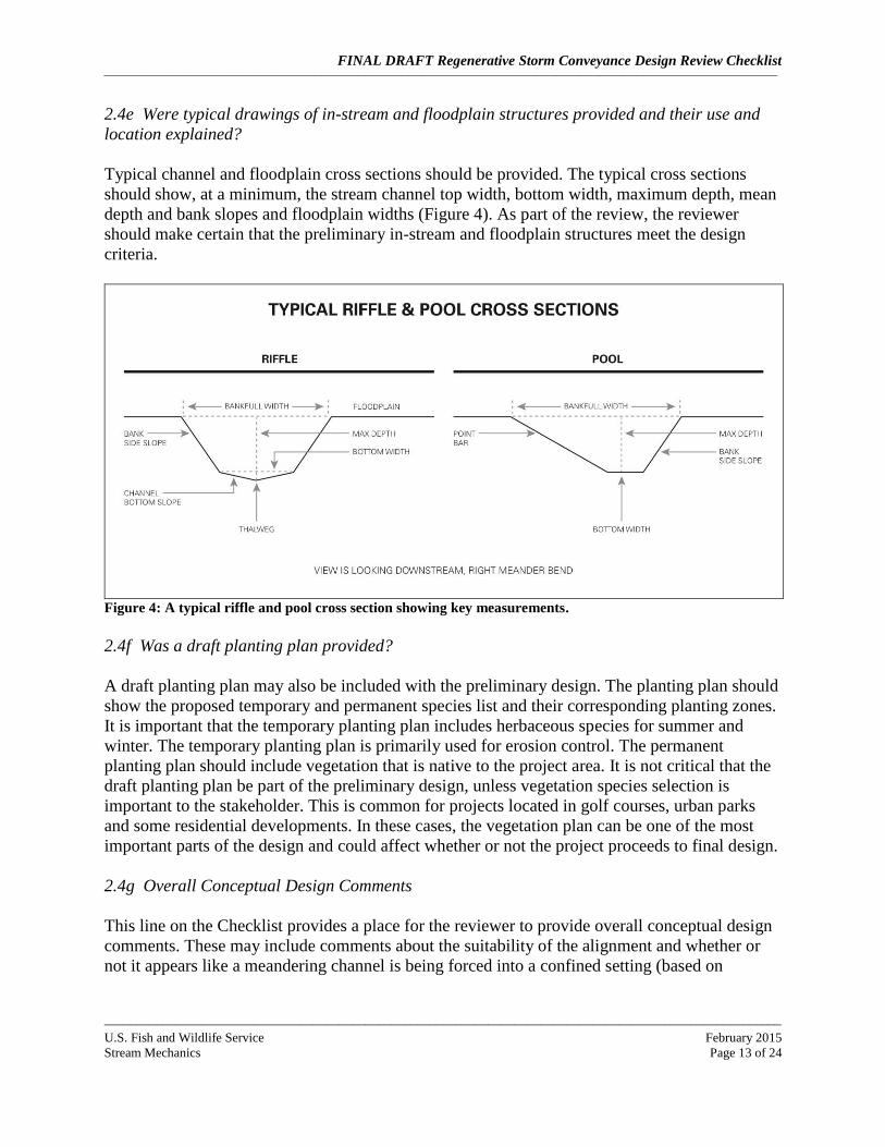
cascades and berms. It is helpful if the existing ground elevation and the cascades and berms elevations are shown on the profile. This information shows if the proposed channel has access to a floodplain at design objective flood flows for the entire length of the project. It is important that the proposed channel not be over topped by the design flood flow. The reviewer should verify that the proposed cross sections, profile and planform are within the design criteria.
Figure 5: Proposed cross section overlaid with the existing ground. These are often shown on a set interval
throughout the length of the project reach and are used by the contractor to excavate the channel and
floodplain (if needed). (Source: U.S. Fish and Wildlife Service, Chesapeake Bay Field Office)
Bankfull Stage
Flood-prone Area Width
Proposed Channel
Existing Ground
FINAL DRAFT Regenerative Storm Conveyance Design Review Checklist
__________________________________________________________________________________________________________________________________________________________________________________________
________________________________________________________________________________________________________
U.S. Fish and Wildlife Service February 2015 Stream Mechanics Page 16 of 24
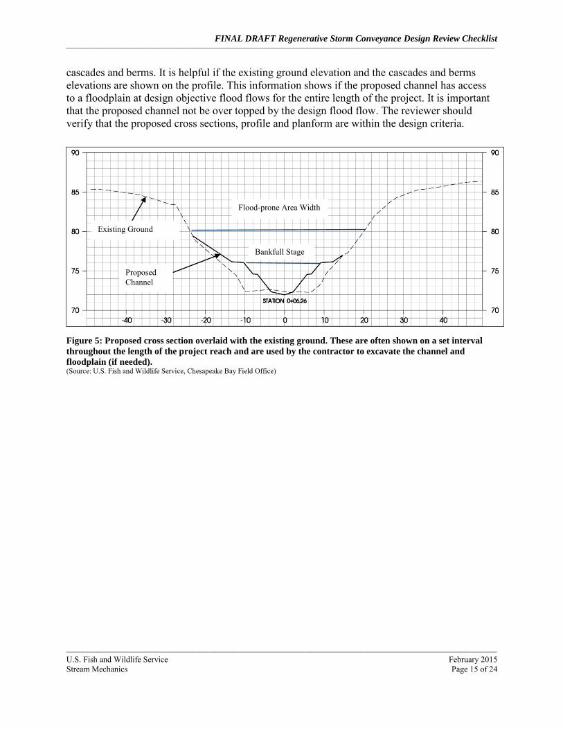
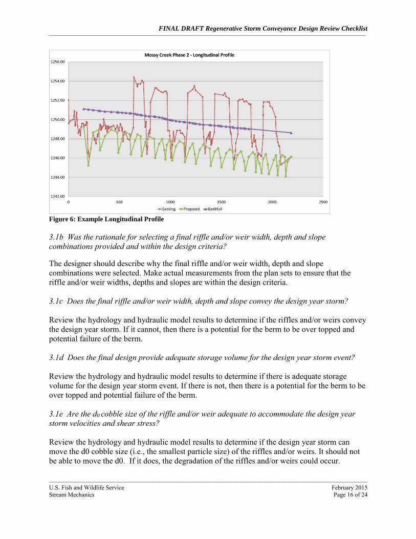
Figure 6: Example Longitudinal Profile 3.1b Was the rationale for selecting a final riffle and/or weir width, depth and slope combinations provided and within the design criteria?
The designer should describe why the final riffle and/or weir width, depth and slope combinations were selected. Make actual measurements from the plan sets to ensure that the riffle and/or weir widths, depths and slopes are within the design criteria. 3.1c Does the final riffle and/or weir width, depth and slope convey the design year storm? Review the hydrology and hydraulic model results to determine if the riffles and/or weirs convey the design year storm. If it cannot, then there is a potential for the berm to be over topped and potential failure of the berm. 3.1d Does the final design provide adequate storage volume for the design year storm event? Review the hydrology and hydraulic model results to determine if there is adequate storage volume for the design year storm event. If there is not, then there is a potential for the berm to be over topped and potential failure of the berm. 3.1e Are the d0 cobble size of the riffle and/or weir adequate to accommodate the design year storm velocities and shear stress? Review the hydrology and hydraulic model results to determine if the design year storm can move the d0 cobble size (i.e., the smallest particle size) of the riffles and/or weirs. It should not be able to move the d0. If it does, the degradation of the riffles and/or weirs could occur.

FINAL DRAFT Regenerative Storm Conveyance Design Review Checklist
__________________________________________________________________________________________________________________________________________________________________________________________
________________________________________________________________________________________________________
U.S. Fish and Wildlife Service February 2015 Stream Mechanics Page 17 of 24
3.1f Are the boulders forming the riffle and/or weir 3 – 4 times larger than the calculated riffle d0? Typically RSC projects are designed for the 100 year storm event and as a result the designers size the smallest riffle and/or weir cobble size to be larger than what the 100 year storm event can move. The 3 to 4 times larger factor for the footers is a safety factor to ensure footers cannot be moved by the 100 year storm event. While the footers are unlikely to be moved by stream energy they can be undermined and thus dislocated. That’s why footer depths are just as critical as footer sizes and is addressed in question 3.1g. 3.1g Were potential pool scour depth provided and are weir and/or cascade footers 2 feet below the potential scour? Pool scour depths must be calculated to ensure that structures will not be undermined. Review the plan set to determine if the structure footer depths are based on the potential scour and 2-foot safety factor. 3.1h If potential pool scour depths are greater than 2 feet below footers, are the pools lined with boulders? There will be situations were footers cannot be placed deeper than the potential scour. In these cases, the entire pool bottom must be lined with boulders to provide resistance to erosion. Review the plans set to identify any structure footer depths that do not met the potential scour depths and determine if they are lined with boulders. If they are not, then there is the potential for the structures to be undermined. 3.1i Were final berm (if part of design) drawings and specifications provided and within the design criteria? Make measurements of the berm from the plan set and determine if the berms were designed to specifications and met design criteria. Specifically look at the materials being used to construct the berm and measure berm heights, top and bottom widths, and bank slopes. 3.1j Was the rationale for providing a final project alignment provided and within the design criteria? The designer should describe why the final project alignment was selected. Make actual measurements from the plan sets to ensure that the alignment follows the natural flow path of the valley and that the upstream and downstream tie-ins connect with the existing stream channel. 3.1k Will the project tie-ins have no change to upstream and downstream existing stability conditions? Stream restoration projects have the potential to change stream stability conditions upstream and downstream of the project area. In most cases it can only prevent changing current upstream and
FINAL DRAFT Regenerative Storm Conveyance Design Review Checklist
__________________________________________________________________________________________________________________________________________________________________________________________
________________________________________________________________________________________________________
U.S. Fish and Wildlife Service February 2015 Stream Mechanics Page 18 of 24
downstream stability conditions. However, there can be times where positive or negative effects could occur. For example, if there is a head cut within the project area that will be halted as part of the restoration actions, then future upstream degradation will be prevented. However, if the proposed stream restoration improves sediment transport, the potential exists for downstream reaches to receive an increase in sediment load. Also, the review should check to see if the upstream and downstream tie-ins reconnect with the existing stream channel alignment. 3.1l Did project constraints like right-of-ways or flood control requirements affect the width/depth/slope section? If so, was the risk of instability described? In some proposed projects, there is limited area for storage of flood flows. In these particular cases, stream energy can adversely affect stream channel and floodplain stability. If this condition exists, the designer should describe how the increased energy will be addressed to reduce stream and floodplain degradation. 3.1m Were specifications for materials and construction procedures provided and explained for the project (e.g., in-stream structures and erosion control measures)? Specifications should be provided that describes construction means and methods, construction sequencing, and the quantity and quality of materials, especially for in-stream structures and erosion-control measures. Examples include the size and type of boulders and shear stress value for erosion-control matting. Specifications are provided for other items as well, but from a stability perspective, it is most important to review the in-stream structures and erosion-control measures. 3.2 In-Stream Structures
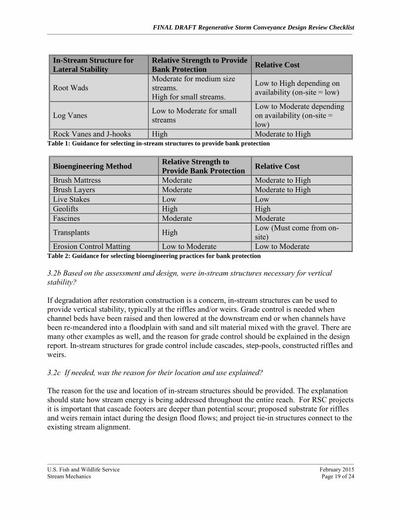
Most, but not all, projects require the use of in-stream structures. An example of a project that may not need in-stream structures are small streams in low gradient valleys, e.g., a small coastal plain stream. In-stream structures are often required in newly constructed channels to provide bank (lateral) and/or bed (vertical) stability. In-stream structures may be constructed from rock or wood depending on their use and availability of materials. Some in-stream structures are also used to improve aquatic habitat. It is important that the right type of structure be used for the right problem and in the appropriate size stream. In all cases, in-stream structures and bank stabilization techniques should be designed after channel geometry has been addressed. In-stream structures cannot typically correct channel pattern problems. 3.2a Based on the assessment and design, were in-stream structures necessary for lateral stability? Most projects will require some type of bank protection to prevent erosion until the permanent vegetation is established. There are a wide range of techniques that can be used, including vanes, root wads, toe wood, erosion control matting, transplants, bioengineering, etc. The type of structure selected should be based on the potential for the bank to erode. The tables below can be used as a general guide for in-stream structures and bioengineering methods.
FINAL DRAFT Regenerative Storm Conveyance Design Review Checklist
__________________________________________________________________________________________________________________________________________________________________________________________
________________________________________________________________________________________________________
U.S. Fish and Wildlife Service February 2015 Stream Mechanics Page 19 of 24
In-Stream Structure for
Lateral Stability
Relative Strength to Provide
Bank Protection Relative Cost
Root Wads Moderate for medium size streams. High for small streams.
Low to High depending on availability (on-site = low)
Log Vanes Low to Moderate for small streams
Low to Moderate depending on availability (on-site = low)
Rock Vanes and J-hooks High Moderate to High Table 1: Guidance for selecting in-stream structures to provide bank protection
Bioengineering Method Relative Strength to
Provide Bank Protection Relative Cost
Brush Mattress Moderate Moderate to High Brush Layers Moderate Moderate to High Live Stakes Low Low Geolifts High High Fascines Moderate Moderate
Transplants High Low (Must come from on-site)
Erosion Control Matting Low to Moderate Low to Moderate Table 2: Guidance for selecting bioengineering practices for bank protection 3.2b Based on the assessment and design, were in-stream structures necessary for vertical stability? If degradation after restoration construction is a concern, in-stream structures can be used to provide vertical stability, typically at the riffles and/or weirs. Grade control is needed when channel beds have been raised and then lowered at the downstream end or when channels have been re-meandered into a floodplain with sand and silt material mixed with the gravel. There are many other examples as well, and the reason for grade control should be explained in the design report. In-stream structures for grade control include cascades, step-pools, constructed riffles and weirs. 3.2c If needed, was the reason for their location and use explained? The reason for the use and location of in-stream structures should be provided. The explanation should state how stream energy is being addressed throughout the entire reach. For RSC projects it is important that cascade footers are deeper than potential scour; proposed substrate for riffles and weirs remain intact during the design flood flows; and project tie-in structures connect to the existing stream alignment.
FINAL DRAFT Regenerative Storm Conveyance Design Review Checklist
__________________________________________________________________________________________________________________________________________________________________________________________
________________________________________________________________________________________________________
U.S. Fish and Wildlife Service February 2015 Stream Mechanics Page 20 of 24
3.2d Will the in-stream structures provide the intended stability? There is an art and science to designing in-stream and floodplain structures and most designers have their own preferences about which structures to use and how to install them. This makes reviewing in-stream structures difficult; however, the reviewer should focus on the relationship between the type of in-stream structure used and its role in providing stability. It is important to look for stream areas that may be vulnerable to short-term erosion (bed or bank) and to make sure that these areas have some form of protection. Examples include medium- to large-size streams with new channel construction and sandy banks. This approach tries to minimize the use of bank-protection structures by storing flood flows within the floodplain. However, the approach does use constructed riffles/knickpoints to provide vertical stability. These structures often extend from the valley edge, across the channel, to the other valley edge. This way the stream can meander, or develop new channels, but it cannot incise. Wood is often buried in the floodplain and sometimes placed in the channel to provide a carbon source. Floodplain vegetation is also critical for providing floodplain stability. 3.2e Were in-stream structures (or changes to geometry) needed to provide stability at tie-in locations with the existing channel? This question is similar to question 3.2.c but focuses on whether in-stream structures are needed to prevent instability from upstream and downstream instability conditions. For example, if there is a headcut downstream of the proposed project area, the designer should demonstrate that grade control will be installed to a depth deeper than the potential degradation associated with the headcut. Or if the upstream channel alignment tie-in will cause severe lateral erosion, the designer should demonstrate how the increased erosion energy will be addressed. Additionally, sometimes stream restoration projects raise the bed elevation and/or change the dimension. For large geometry and profile changes, the designer may need to provide a transition reach into and out of the project reach. For the upstream section, this might mean creating sediment trap areas (splays. For the downstream tie-in, in-stream structures are typically used. These may include some type of step-pool channel or riffle grade control. The reviewer should look for evidence that the designer considered tie-ins as part of the overall stability of the project. 3.2f Were detail drawings provided for each type of in-stream structure? Detail drawings should be provided for each type of in-stream structure or erosion control measure. These drawings are typically part of the plan set, but key structures could be included in the report. The reviewer should check to see if these structures are appropriate given the restoration approach, need for vertical and/or lateral stability, habitat needs and constraints.
FINAL DRAFT Regenerative Storm Conveyance Design Review Checklist
__________________________________________________________________________________________________________________________________________________________________________________________
________________________________________________________________________________________________________
U.S. Fish and Wildlife Service February 2015 Stream Mechanics Page 21 of 24
3.3 Vegetation Design
3.3a Was a vegetation design provided? Every stream restoration project should have a vegetation design tailored to the needs of the project. Too often, boiler plate vegetation designs are included that do not address specific site needs or the goals and objectives of the project. 3.3b Does the design address the use of permanent vegetation for long-term stability? The vegetation design should include temporary and permanent planting plans. The temporary planting plan is used for erosion control because it quickly establishes an herbaceous cover. The species used are often governed by local erosion and sedimentation control laws. The permanent vegetation plan should include native grasses, shrubs and trees (as appropriate for the region) and should be shown in zones, such as along the streambank, floodplains and terraces. 3.3c Overall Final Design Comments This section provides a place for overall final design comments based on the questions above. The reviewer can address major concerns or apparent deficiencies in the design and request additional information if necessary. 4.0 Overall Design Review This last section incorporates all of the above information into a final review. The goal here is to determine the overall likelihood of success. 4.0a Does the design address the project goals and objectives? Based on the results from the above questions, the reviewer should determine if the design addresses the project goals and objectives. For example, if the objective was to reduce incision and bank erosion, the design should show reductions in the bank height ratio and provide connectivity to an adjacent floodplain or flood-prone area. 4.0b Are there any design components that are missing or could adversely affect the success of the project? In addition, the reviewer should take another overall look at the design to determine if there are any critical elements that are missing or that could adversely affect the success of the project. For example, if there is a large upstream sediment supply from eroding banks, a sediment transport analysis is critical to designing a stable channel.

FINAL DRAFT Regenerative Storm Conveyance Design Review Checklist
__________________________________________________________________________________________________________________________________________________________________________________________
________________________________________________________________________________________________________
U.S. Fish and Wildlife Service February 2015 Stream Mechanics Page 22 of 24
4.0c Does the project have a high potential for success? Based on all of the above information, the reviewer should determine if the project has a high potential for success, or if the risk of failure outweighs the potential for functional lift. If the project is considered too risky, specific concerns should be given. This will provide the designer with an opportunity to address and potentially remedy the concerns.
FINAL DRAFT Regenerative Storm Conveyance Design Review Checklist
__________________________________________________________________________________________________________________________________________________________________________________________
________________________________________________________________________________________________________
U.S. Fish and Wildlife Service February 2015 Stream Mechanics Page 23 of 24
5.0 References
Copeland, R.R, D.N. McComas, C.R. Thorne, P.J. Soar, M.M. Jones and J.B. Fripp. 2001. Hydraulic Design of Stream Restoration Projects. United States Army Corps of Engineers (USACOE), Washington, D.C. ERDC/CHL TR-01-28. http://stinet.dtic.mil/cgi-bin/GetTRDoc?AD=ADA400662&Location=U2&doc=GetTRDoc.pdf Doll, B.A., G.L. Grabow, K.R. Hall, J. Halley, W.A. Harman, G.D. Jennings and D.E. Wise. 2003. Stream Restoration: A Natural Channel Design Handbook. NC Stream Restoration Institute, NC State University. 128 pp. http://www.bae.ncsu.edu/programs/extension/wqg/srp/sr_guidebook.pdf Federal Interagency Stream Restoration Working Group (FISRWG). 1998. Stream Corridor Restoration: Principles, Processes, and Practices. GPO item No. 0120-A; SuDocs No. A 57.6/2:EN 3/PT.653. ISBN-0-934213-59-3. http://www.nrcs.usda.gov/technical/stream_restoration/ Flores, H. 2011. Design Guidelines for Step Pool Storm Conveyance. Anne Arundel County Government Department of Public Works, Bureau of Engineering. Annapolis, MD. Harman, W.A., G.D. Jennings, J.M. Patterson, D.R. Clinton, L.O. Slate, A.G. Jessup, J.R. Everhart and R.E. Smith. 1999. Bankfull Hydraulic Geometry Relationships for North Carolina Streams. In: Wildland Hydrology Proceedings, Darren S Olsen and John P. Potyondy (Editors). AWRA. TPS-99-3, pp. 401-408. Harman, W.A. 2000. River Course Fact Sheet No. 3: Finding Bankfull Stage in North Carolina Streams. NC Stream Restoration Institute, North Carolina State University. AG-590-3. http://www.bae.ncsu.edu/programs/extension/wqg/srp/rv-crs-3.pdf Harman, W., R. Starr. 2011. Natural Channel Design Review Checklist. US Fish and Wildlife Service, Chesapeake Bay Field Office, Annapolis, MD and US Environmental Protection Agency, Office of Wetlands, Oceans, and Watersheds, Wetlands Division. Washington, D.C. EPA 843-B-12-005. Harman, W., R. Starr, M. Carter, K. Tweedy, M. Clemmons, K. Suggs, C. Miller. 2012. A Function-Based Framework for Stream Assessment and Restoration Projects. U.S. Environmental Protection Agency, Office of Wetlands, Oceans, and Watersheds, Washington, D.C. EPA 843-K-12-006. Hey, R.D. 2006. Fluvial Geomorphological Methodology for Natural Stable Channel Design. Journal of American Water Resources Association. April 2006. Vol. 42, No. 2. pp. 357-374. AWRA Paper No. 02094. http://www.awra.org/jawra/papers/J02094.html Leopold, L.B., M.G. Wolman, J.P. Miller. 1992. Fluvial Processes in Geomorphology. Dover Publications, Inc. New York.
FINAL DRAFT Regenerative Storm Conveyance Design Review Checklist
__________________________________________________________________________________________________________________________________________________________________________________________
________________________________________________________________________________________________________
U.S. Fish and Wildlife Service February 2015 Stream Mechanics Page 24 of 24
McCandless, T.L. and R.A. Everett. 2002. Maryland Stream Survey: Bankfull Discharge and Channel Characteristics in the Piedmont Hydrologic Region. U.S. Fish and Wildlife Service, Annapolis, MD. CBFO-S02-02. http://www.fws.gov/chesapeakebay/streampub.htm NRCS. 2007. Part 654 – Stream Restoration Design. USDA, Natural Resources Conservation Service. H.210.NEH.654. http://policy.nrcs.usda.gov/index.aspx Rosgen, D.L. 1998. The Reference Reach – A Blueprint for Natural Channel Design (Draft). ASCE Conference on River Restoration, Denver, CO. March, 1998. ASCE. Reston, VA. http://www.wildlandhydrology.com/assets/The_Reference_Reach_II.pdf Rosgen, D.L. 2006a. Watershed Assessment of River Stability and Sediment Supply (WARSSS). Wildland Hydrology. Fort Collins, CO. http://www.epa.gov/warsss/ Rosgen, D.L. 2006b. The Cross-Vane, W-Weir and J-Hook Vane Structures (Updated 2006). Their Description, Design and Application for Stream Stabilization and River Restoration. Wildland Hydrology, Inc., Ft. Collins, CO. http://www.wildlandhydrology.com/assets/The_Cross_Vane_W-Weir_and_J-Hook_Structures_Paper_Updated_2006%20.pdf USDA-NRCS, 2007. Part 654 National Engineering Handbook. 210.VI.NEH, August 2007). http://directives.sc.egov.usda.gov/viewerFS.aspx?hid=21433. Wilcock, P., J.Pitlick and Y. Cui. 2009. Sediment Transport Primer, Estimating Bed-Material Transport in Gravel-bed Streams. United States Department of Agriculture, Forest Service. Rocky Mountain Research Station. General Technical Report RMRS-GTR-226. May, 2009.

Regenerative Storm Conveyance Design Review Checklist
Appendices


Appendix A
DRAFT RSC Design Review Checklist Page 1 of 3 September 9, 2014
Project Design Checklist Reviewer:Date:
Project:Engineer:
Submitted(Y/N/P)
Acceptable(Y/N/P) Page #
2.2a Is the proposed design approach appropriate given the size of the DA?
2.1g Did the sediment analysis show the potential for the stream channel and floodplain to aggrade or degrade after analyzing multiple discharges?
2.1d Was a sediment transport analysis completed upstream (supply) and within project reach using a range of sediment transport rates?
2.1e Was sediment transport measured?
1.2c Was stream velocity, shear stress and stream power shown in relation to stage and discharge?
2.0 Preliminary Design2.1 Sediment Transport
2.2 Goals and Restoration Potential
2.1h If the reach has a sediment supply, does the design state how it will be addressed?
2.1f Were multiple discharges used to evaluate channel and floodplain stability?
2.1a Did the sediment transport analysis include an evaluation of sediment supply (i.e., sediment supply amount and source(s))?2.1b Was a model used to calculate sediment transport described, including assumptions and applicability to project reach conditions?2.1c Was SAM, HEC-RAS, 2-D modelling or other tools used to determine stable channel and floodplain dimensions based on sediment transport and/or resistance to shear stress?
1.1 Basemapping1.1a Does the project include basemapping?
1.2 Hydraulic Assessment
1.2b Was a hydraulic assessment completed?
1.2a Was the project drainage area provided?
2.2b Does the project have clear goals and measurable objectives?
CommentsItem
1.0 Basemapping and Hydraulic Assessment
2.2c Was the restoration potential based on the assessment data provided?
REGENERATIVE STORM CONVEYANCE DESIGN REVIEW CHECKLIST
2.2d Was a restoration strategy developed and explained based on the restoration potential?

Appendix A
DRAFT RSC Design Review Checklist Page 2 of 3 September 9, 2014
Submitted(Y/N/P)
Acceptable(Y/N/P) Page # CommentsItem
3.1b Was the rationale for selecting a final riffle and/or weir width, depth and slope combinations provided and within the design criteria?
3.1 RSC Restoration Design
2.4b Were typical riffle, weir and floodplain cross sections provided and developed within the design width, depth and slope ranges?
2.3g Were hydrology and hydraulic models used to determine and test stability of berm heights and widths (if part of design)?
2.4d Were typical berm height and width cross sections and profiles provided and within the design criteria?
2.3j Were any other design criteria provided and explained?
2.4c Were typical cascade drawings provided and developed within the design criteria?
3.1a Were final cross sections, profile and planform provided?
2.4e Were typical drawings of in-stream and floodplain structures provided and their use and location explained?
2.4f Was a draft planting plan provided?
3.0 Final Design
3.1c Does the final riffle and/or weir width, depth and slope convey the design year storm?
3.1e Are the d0 cobble size of the riffle and/or weir adequate to accommodate the design year storm velocities and shear stress?
2.3f Was design criteria for sand seepage berms (if part of design) provided?
2.3i Was the design discharge compared to bankfull discharge from appropriate regional curve?
2.3b Was the method used to determine riffle and/or weir widths and depths described?2.3c Were fluvial geomorphic principles used to select the dependent variable, e.g., width?
2.3h Were the methods used to design the plan form and bed forms described?
2.3e Was the method used to determine cascade height (if part of design) described?
3.1d Does the final design provide adequate storage volume for the design year storm event?
2.4a Was the conceptual channel alignment provided and developed within the design width and slope range and follow the natural drainage path of the valley?
2.3k Are the design criteria appropriate given the site conditions and restoration potential?
2.3d Were hydrology and hydraulic models used to determine the riffle and/or weir design width, depth and slope?
2.3a Were design criteria provided and explained?
2.4 Conceptual Design
2.3 Design Criteria
2.4g Overall Conceptual Design Comment(s)

Appendix A
DRAFT RSC Design Review Checklist Page 3 of 3 September 9, 2014
Submitted(Y/N/P)
Acceptable(Y/N/P) Page # CommentsItem
3.1g Were potential pool scour depth provided and are weir and/or cascade footers 2 feet below the potential scour?
3.2a Based on the assessment and design, were in-stream structures necessary for lateral stability?
3.2e Were in-stream structures (or changes to geometry) needed to provide stability at tie-in locations with the existing channel?
3.2c If needed, was the reason for their location and use explained?
3.1i Were final berm (if part of design) drawings and specifications provided and within the design criteria?
3.3b Does the design address the use of permanent vegetation for long term stability?
4.0b Are there any design components that are missing or could adversely affect the success of the project?
3.2b Based on the assessment and design, were in-stream structures needed for vertical stability?
3.2d Will the in-stream structures provide the intended stability?
3.2f Were detail drawings provided for each type of in-stream and/or floodplain structure?
3.3a Was a vegetation design provided?3.3 Vegetation Design
4.0 Overall Design Review
3.2 In-Stream and Floodplain Structures
3.1f Are the boulders forming the riffle and/or weir 3 - 4 times larger than the calculated riffle d0?
4.0a Does the design address the project goals and objectives?
3.1k Will the project tie-ins have no change to upstream and downstream existing stability conditions?
3.3c Overall Final Design Comment(s)
3.1h If potential pool scour depths are greater than 2 feet below footers, are the pools lined with boulders?
4.0c Does the project have a high potential for success?
3.1l Did project constraints like right-of-ways or flood control requirements affect the channel width/depth/slope section? If so, was the risk of instability described?3.1m Were specifications for materials and construction procedures provided and explained for the project (i.e., in-stream structures and erosion control measures)?
3.1j Was the rationale for providing a final project alignment provided and within the design criteria?

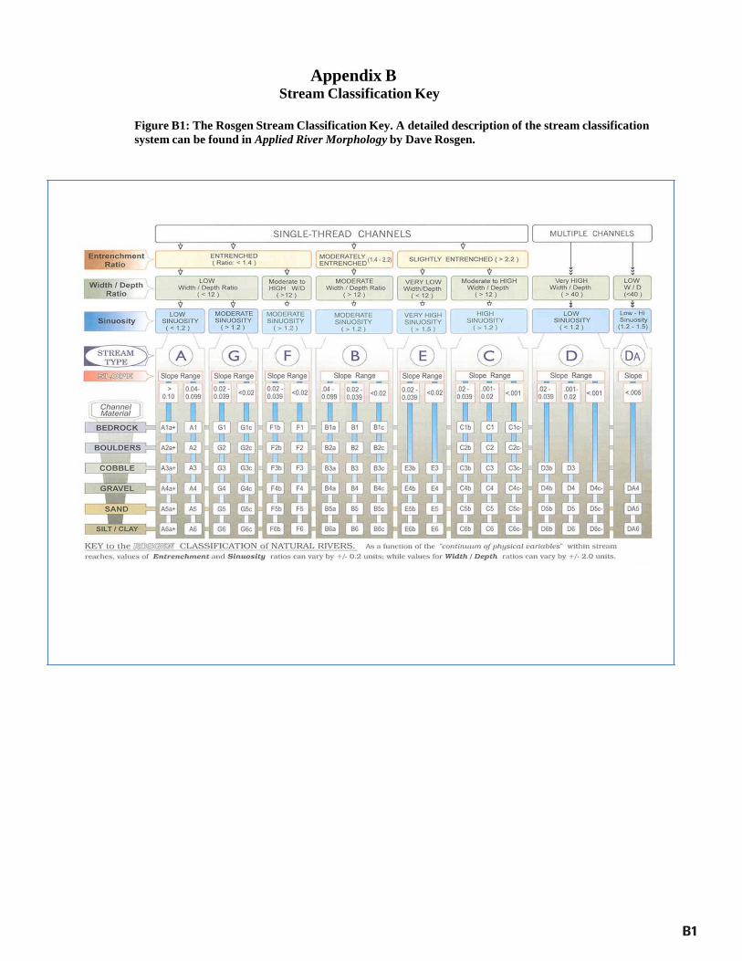
Appendix B Stream Classification Key
Figure B1: The Rosgen Stream Classification Key. A detailed description of the stream classification system can be found in Applied River Morphology by Dave Rosgen.
B1

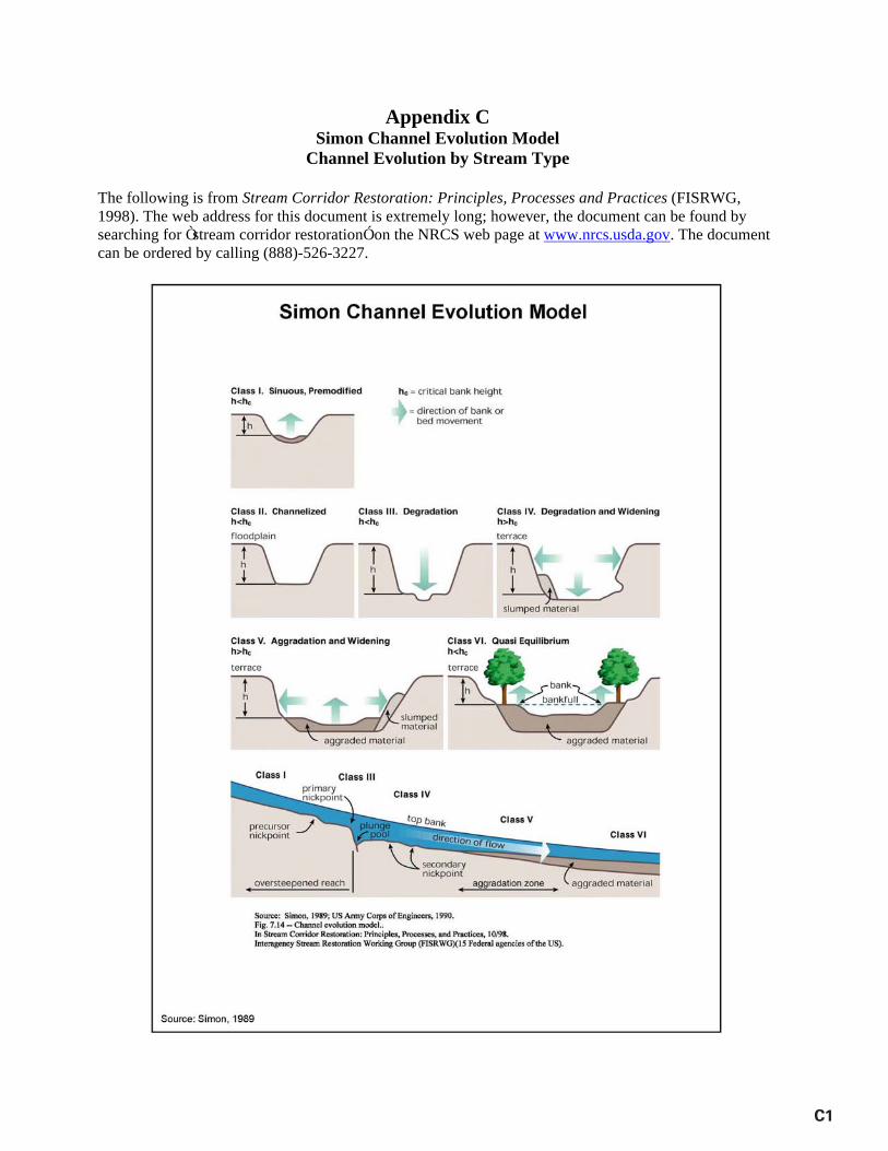
Appendix C Simon Channel Evolution Model
Channel Evolution by Stream Type
The following is from Stream Corridor Restoration: Principles, Processes and Practices (FISRWG, 1998). The web address for this document is extremely long; however, the document can be found by searching for Ò stream corridor restorationÓ on the NRCS web page at www.nrcs.usda.gov. The document can be ordered by calling (888)-526-3227.
C1
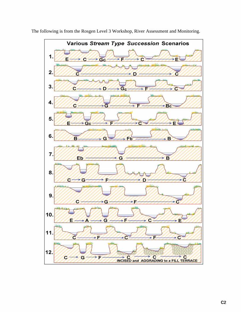
The following is from the Rosgen Level 3 Workshop, River Assessment and Monitoring.
C2
D1
Appendix D Regional Curves and ManningÕ s Equation
The following list of regional curves is an excerpt from Appendix A of Stream Assessment and Mitigation Protocols: A Review of Commonalities and Differences by Somerville (2010). The entire document can be downloaded from http://water.epa.gov/lawsregs/guidance/wetlands/wetlandsmitigation_index.cfm or http://stream-mechanics.com/resources-html/. Hydraulic Regional Curves for Selected Areas of the United States NOTE: Not all of the following references have been subject to the same level of independent review. In addition to investigations published in peer-reviewed literature, this list also includes works undertaken pursuant to university degree programs and specific restoration projects carried out by both the private and public sector. Moreover, some references are the result of symposia, workshops, etc., and information contained therein may have had little review outside of the individual documentÕ s collaborators. ALABAMA Metcalf, C. 2005. Alabama riparian reference reach and regional curve study. U.S. Fish and Wildlife Service, Panama City Fisheries Resource Office. Panama City, FL. ARIZONA Moody, T. and W. Odem. 1999. Regional relationships of bankfull stage in central and southern Arizona, in D.S. Olsen and J.P. Potyondy (eds), Wildland Hydrology, American Water Resources Association Specialty Conference Proceedings, June 20-July 2, 1999: Bozeman, MT, TPS-99-3, 536 p. Moody, T., M. Wirtanen and S.N. Yard. 2003. Regional Relationships for Bankfull Stage in Natural Channels of the Arid Southwest, Natural Channel Design, Inc. Flagstaff, AZ. 38 p. http://www.naturalchanneldesign.com/NCD%20Reports.htm CALIFORNIA Dunne, T.D. and L.B. Leopold. 1978. Water in Environmental Planning. W.H. Freeman and Company, NY.818 p. COLORADO Elliot, J.G. and K.D. Cartier. 1986. Hydraulic geometry and streamflow of channels in the Piceance Basin, Rio Blanco and Garfield Counties, Colorado. U.S. Geological Survey Water Resources Investigations Report 85-4118. http://pubs.er.usgs.gov/usgspubs/wri/wri854118 Yochum, S. 2003. Regional Bankfull Characteristics for the Lower Willow Creek Stream Restoration, USDA NRCS Northern Plains Engineering Team, Lakewood, CO. 22 p. http://www.willowcreede.org/floodcontrol/WillowCreekRegionalBankfullCharacteristics.pdf
D2
FLORIDA Metcalf, C. 2004. Regional Channel Characteristics for Maintaining Natural Fluvial Geomorphology in Florida Streams. U.S. Fish and Wildlife Service, Panama City Fisheries Resource Office. Panama City, FL. Metcalf, C.K., S.D. Wilkerson, and W.A. Harman. 2009. Bankfull regional curves for north and northwest Florida streams. Journal of the American Water Resources Association 45(5): 1260-1272. GEORGIA Pruitt, B.A. 2001. Hydrologic and soil conditions across hydrogeomorphic settings. PhD dissertation, University of Georgia, Athens, GA. 223.p. http://www.libs.uga.edu/science/ IDAHO Emmet, W.W. 1975. The channels and waters of the Upper Salmon River area, Idaho. U.S. Geologic Survey, Professional Paper 870-A. U.S. Government Printing Office, Washington, D.C. 116 p. KANSAS Emmert, B.A. 2004. Regional curve development for Kansas. In J.L. DÕ Ambrosio (ed). Proceedings Self-Sustaining Solutions for Streams, Wetlands, and Watersheds, 12-15, September 2004. St. Paul, Minnesota. American Society of Agricultural Engineers, St. Joseph, MI. http://asae.frymulti.com/conference.asp?confid=sww2004 KENTUCKY Mater, B.D., A.C. Parola, Jr., C. Hansen and M.S. Jones. 2009. Geomorphic Characteristics of Streams in the Western Kentucky Coal Field Physiographic Region of Kentucky. Final Report prepared by University of Louisville, Stream Institute for the Kentucky Division of Water, Frankfort, KY. http://water.ky.gov/permitting/Lists/Working%20in%20Streams%20and%20Wetlands/Attachments/10/WesternKYCoalfields.pdf Parola, A.C., Jr., K. Skinner, A.L. Wood-Curini, W.S. Vesely, C, Hansen, and M.S. Jones. 2005. Bankfull Characteristics of Select Streams in the Four Rivers and Upper Cumberland River Basin Management Units. Final Report prepared by University of Louisville, Stream Institute for the Kentucky Division of Water, Frankfort, KY. Parola, A.C., Jr., W.S. Vesely, A.L. Wood-Curini, D.J. Hagerty, M.N. French, D.K. Thaemert and M.S. Jones. 2005. Geomorphic Characteristics of Streams in the Mississippi Embayment Physiographic Region of Kentucky. Final Report prepared by University of Louisville, Stream Institute for the Kentucky Division of Water, Frankfort, KY. http://water.ky.gov/permitting/Lists/Working%20in%20Streams%20and%20Wetlands/Attachments/10/WesternKYCoalfields.pdf
D3
Parola, A.C., Jr., W.S. Vesely, M.A. Croasdaile, C. Hansen, and M.S. Jones. 2007. Geomorphic Characteristics of Streams in the Bluegrass Physiographic Region of Kentucky. Final Report prepared by University of Louisville, Stream Institute for the Kentucky Division of Water, Frankfort, KY. http://water.ky.gov/permitting/Lists/Working%20in%20Streams%20and%20Wetlands/Attachments/8/Bluegrassstreamsreport.pdf Pruitt, B.A., W.L. Nutter, and W.B. Ainslie. 1999. Estimating flood frequency in gaged and ungaged watersheds, In K.J. Hatcher (ed.) Proceedings of the 1999 Georgia Water Resources Conference, March 30-31, 1999, University of Georgia, Athens, GA. http://www.gwri.gatech.edu/uploads/proceedings/1999/PruittB-99.pdf Vesely, W.S., A.C. Parola, Jr., C. Hansen and M.S. Jones. 2008. Geomorphic Characteristics of Streams in the Eastern Kentucky Coal Field Physiographic Region of Kentucky. Final Report prepared by University of Louisville, Stream Institute for the Kentucky Division of Water, Frankfort, KY. http://water.ky.gov/permitting/Lists/Working%20in%20Streams%20and%20Wetlands/Attachments/9/EasternKYCoalfields.pdf MAINE Dudley, R.W. 2004. Hydraulic geometry relations for rivers in coastal and central Maine: U.S. Geological Survey Scientific Investigations Report: 2004-5042, 30 p. http://water.usgs.gov/pubs/sir/2004/5042/ MARYLAND Chaplin, J.J. 2005. Development of regional curves relating bankfull-channel geometry and discharge to drainage area for streams in Pennsylvania and selected areas of Maryland, U.S. Geologic Survey, Scientific Investigations Report 2005-5147. Cinotto, P.J. 2003. Development of regional curves of bankfull-channel geometry and discharge for streams in non-urban Piedmont Physiographic Province, Pennsylvania and Maryland: U.S. Geological Survey Water-Resources Investigations Report 03-4014, 27 p. http://pa.water.usgs.gov/reports/wrir03-4014.pdf Doheny, E.J. and G.T. Fisher. 2007. Hydraulic geometry characteristics of continuous record streamflow-gaging stations on four urban watersheds along the main stem of Gwynns Falls, Baltimore County and Baltimore City, Maryland: U.S. Geological Survey Scientific Investigations Report 2006Ð 5190, 24 p. http://pubs.usgs.gov/sir/2006/5190/ Keaton, J.N., T. Messinger and E.J. Doheny. 2005. Development and analysis of regional curves for streams in the non-urban valley and Ridge physiographic provinces, Maryland, Virginia, and West Virginia: U.S. Geological Survey Scientific Report 2005-5076, 116 p. http://pubs.usgs.gov/sir/2005/5076/sir05_5076.pdf
D4
Krstolic, J.L. and J.J. Chaplin. 2007. Bankfull regional curves for streams in the non-urban, non-tidal Coastal Plain Physiographic Province, Virginia and Maryland: U.S. Geological Survey Scientific Investigations Report 2007Ð 5162, 48 p. http://pubs.usgs.gov/sir/2007/5162/pdf/SIR2007-5162.pdf McCandless, T.L. and R.A. Everett. 2002. Maryland stream survey: bankfull discharge and channel characteristics of streams in the Piedmont hydrologic region: U.S. Fish and Wildlife Service, Annapolis, Maryland, CBFO-S02-01, 163 p. http://www.fws.gov/chesapeakebay/pdf/Piedmont.pdf McCandless, T.L. and R.A. Everett. 2003. Maryland stream survey: bankfull discharge and channel characteristics of streams in the Allegheny Plateau and the Valley and Ridge hydrologic region: U.S. Fish and Wildlife Service, Annapolis, Maryland, CBFOS03-01, 92 p. http://www.fws.gov/chesapeakebay/pdf/plateauweb.pdf McCandless, T.L. 2003. Maryland stream survey: bankfull discharge and channel characteristics of streams in the Coastal Plain hydrologic region: U.S. Fish and Wildlife Service, Annapolis, Maryland, CBFO-S03-02, 89 p. http://www.fws.gov/chesapeakebay/pdf/plain.pdf Miller, K.F. 2003. Assessment of channel geometry data through May 2003 in the mid-Atlantic highlands of Maryland, Pennsylvania, Virginia, and West Virginia: U.S. Geological Survey Open-File Report 03-388, 22 p. White, K.E. 2001. Regional curve development and selection of a references reach in the non-urban lowland sections of the piedmont physiographic province, Pennsylvania and Maryland: U.S. Geological Survey Water-Resources Investigations Report 01-4146, 20 p. http://pa.water.usgs.gov/reports/wrir01-4146.pdf MASSACHUSETTES Bent, G.C. and A.M. Waite. (In review). Methods for estimating bankfull channel geometry and discharge for streams in Massachusetts: U.S. Geological Survey Scientific Investigations Report 2008Ð XXXX, XX p. MICHIGAN Mistak, J.L. and D.A. Stille. 2008. Regional hydraulic geometry curve for the Upper Menominee River, Fisheries Technical Report 2008-1, Michigan Department of Natural Resources, Lansing, MI. http://www.michigan.gov/deq/0,1607,7-135-3313_3684_41228-141575--,00.html Rachol, C.M. and K. Boley-Morse. 2009. Estimated Bankfull Discharge for Selected Michigan Rivers and Regional Hydraulic Geometry Curves for Estimating Bankfull Characteristics in Southern Michigan Rivers. U.S. Geologic Survey, Scientific Investigations Report 2009-5133, 300 pp. http://pubs.er.usgs.gov/usgspubs/sir/sir20095133
D5
MINNESOTA Padmanabhan, G. and B.H. Johnson. 2010. Regional Dimensionless Rating Curves to Estimate Design Flows and Stages. Journal of Spatial Hydrology 10(1): 41-75. http://www.spatialhydrology.com/journal/papersping2010/Regional%20Dimensionles s%20Rating%20Curves.pdf MONTANA Lawlor, S.M. 2004. Determination of Channel-Morphology Characteristics, Bankfull Discharge, and Various Design-Peak Discharges in Western Montana. U.S. Geologic Survey, Scientific Investigations Report 2004-5263, Reston, VA. http://pubs.usgs.gov/sir/2004/5263/ NEW ENGLAND Bent, G.C. 2006. Equations for estimating bankfull-channel geometry and discharge for streams in the northeastern United States, In Proceedings of the Joint Federal Interagency Conference, 3rd Federal Interagency Hydrologic Modeling Conference and 8th Federal Interagency Sedimentation Conference, Reno, Nevada, April 2-6, 2006. http://pubs.usgs.gov/misc/FISC_1947-2006/pdf/1st-7thFISCs-CD/8thFISC/8thFISC.pdf NEW MEXICO Jackson, F. 1994. Documenting channel condition in New Mexico. Stream Notes Special Summer Issue 1994, Stream Systems Technology Center, U.S. Forest Service, Fort Collins, CO. pg 3-5. Moody, T., M. Wirtanen and S.N. Yard. 2003. Regional Relationships for Bankfull Stage in Natural Channels of the Arid Southwest, Natural Channel Design, Inc. Flagstaff, AZ. 38 p. http://www.naturalchanneldesign.com/NCD%20Reports.htm NEW YORK Baldigo, B. 2004. Regionalization of channel geomorphology characteristics for streams of New York State, excluding Long Island: U.S. Geological Survey, New York Water Science Center. http://ny.water.usgs.gov/projects/summaries/2457-A29-1.html Bent, G.C. 2006. Equations for estimating bankfull-channel geometry and discharge for streams in the northeastern United States: Proceedings of the Joint Federal Interagency Conference, Book of Abstracts, 3rd Federal Interagency Hydrologic Modeling Conference and 8th Federal Interagency Sedimentation Conference, Reno, NV, April 2-6, 2006, 314 p. Miller, S.J. and D. Davis. 2003. Optimizing Catskill Mountain regional bankfull discharge and hydraulic geometry relationships: Proceedings of the American Water Resources Association, 2003 International Congress, Watershed management for water supply systems, New York City, NY, June 29-July 2, 2003, 10 p. http://home2.nyc.gov/html/dep/pdf/resources/smp.pdf Mulvihill, C.I., A.G. Ernst and B.P. Baldigo. 2005. Regionalized equations for bankfull discharge and channel characteristics of streams in New York state: hydrologic region 6 in the southern tier of New York: U.S. Geological Survey Scientific Investigations Report 2005-5100, 21 p. http://ny.water.usgs.gov/pubs/wri/sir055100/sir2005-5100.pdf
D6
Mulvihill, C.I., A.G. Ernst and B.P. Baldigo. 2006. Regionalized equations for bankfull discharge and channel characteristics of streams in New York State: hydrologic region 7 in western New York: U.S. Geological Survey Scientific Investigations Report 2006-5075, 14 p. http://ny.water.usgs.gov/pubs/wri/sir065075/sir2006-5075.pdf Mulvihill, C.I., A. Filopowicz, A. Coleman and B.P. Baldigo. 2007. Regionalized equations for bankfull discharge and channel characteristics of streams in New York StateÑ hydrologic regions 1 and 2 in the Adirondack region of northern New York: U.S. Geological Survey Scientific Investigations Report 2007-5189, 18 p. http://pubs.usgs.gov/sir/2007/5189/ Mulvihill, C.I. and B.P. Baldigo. 2007. Regionalized equations for bankfull discharge and channel characteristics of streams in New York StateÑ hydrologic region 3 east of the Hudson River: U.S. Geological Survey Scientific Investigations Report 2007Ð 5227, 15 p. http://pubs.usgs.gov/sir/2007/5227/pdf/SIR2007-5227.pdf Powell, R.O., S.J. Miller, B.E. Westergard, C.I. Mulvihill, B.P. Baldigo, A.S. Gallagher and R.R. Starr. 2004. Guidelines for surveying bankfull channel geometry and developing regional hydraulic-geometry relations for streams of New York State: U.S. Geological Survey Open-File Report 03-092, 20 p. http://ny.water.usgs.gov/pubs/of/of03092/of03-092.pdf Westergard, B.E., C.I. Mulvihill, A.G. Ernst and B.P. Baldigo. 2005. Regional equations for bankfull discharge and channel characteristics of stream in New York State -hydrologic region 5 in central New York: U.S. Geological Survey Scientific Investigations Report 2004-5247, 16p. http://ny.water.usgs.gov/pubs/wri/sir045247/ NORTH CAROLINA Doll, B.A., A.D. Dobbins, J. Spooner, D.R. Clinton and D.A. Bidelspach. 2003. Hydraulic geometry relationships for rural North Carolina Coastal Plain streams, NC Stream Restoration Institute, Report to NC Division of Water Quality for 319 Grant Project No. EW20011, 11 pp. http://www.bae.ncsu.edu/programs/extension/wqg/srp/techresources.html Doll, B.A., D.E. Wise-Frederick, C.M. Buckner, S.D. Wilkerson, W.A. Harman, R.E. Smith and J. Spooner. 2002. Hydraulic geometry relationships for urban streams throughout the Piedmont of North Carolina. Journal of the American Water Resources Association 38(3): 641-651. Harman, W.H., G.D. Jennings, J.M. Patterson, D.R. Clinton, L.O. Slate, A.G. Jessup, J.R. Everhart and R.E. Smith. 1999. Bankfull hydraulic geometry relationships for North Carolina streams, in D.S. Olsen and J.P. Potyondy (eds) Proc. Wildland Hydrology Symposium, June 30-July 2, 1999, Bozeman, MT. American Water Resources Association. http://www.bae.ncsu.edu/programs/extension/wqg/srp/techresources.html
D7
Harman, W.H., D.E. Wise, M.A. Walker, R. Morris, M.A. Cantrell, M. Clemmons, G.D. Jennings, D. Clinton and J. Patterson. 2000. Bankkfull regional curves for North Carolina mountain streams, Pgs 185-190 in D.L. Kane (ed) Proc. AWRA Conference on Water Resources in Extreme Environments, Anchorage, AK. http://www.bae.ncsu.edu/programs/extension/wqg/srp/techresources.html Sweet, W.V., and J.W. Geratz. 2003. Bankfull hydraulic geometry relationships and recurrence for North CarolinaÕ s Coastal Plain. Journal of the American Water Resources Association 39(4): 861-871. NORTH DAKOTA Padmanabhan, G. and B.H. Johnson. 2010. Regional Dimensionless Rating Curves to Estimate Design Flows and Stages. Journal of Spatial Hydrology 10(1): 41-75. OHIO Chang, T.J., Y.Y. Fang, H. Wu and D.E. Mecklenburg. 2004. Bankfull channel dimensions in southeast Ohio, in Proceedings of the Self-Sustaining Solutions for Streams, Wetlands, and Watersheds Conference, American Society of Agricultural Engineers, September 2004: 9 p. Sherwood, J.M. and C.A. Huitger. 2005. Bankfull characteristics of Ohio streams and their relation to peak streamflows: U.S. Geological Survey Scientific Investigations Report 2005-5153, 38 p. http://pubs.usgs.gov/sir/2005/5153/pdf/Bankfull_book.pdf OKLAHOMA Dutnell, R.C. 2010. Development of Bankfull Discharge and Channel Geometry Relationships for Natural Channel Design in Oklahoma Using a Fluvial Geomorphic Approach, Masters Thesis, University of Oklahoma, Norman, OK. 95 p. http://www.riverman-engineering.com/index_files/Page473.htm OREGON Kuck, T.D. 2000. Regional Hydraulic Geometry Curves of the South Umpqua Area in Southwestern Oregon. Stream Notes, January 2000, Stream Systems Technology Center, USDA Forest Service, Rocky Mountain Research Station, Ft. Collins, CO. http://stream.fs.fed.us/news/streamnt/pdf/SN_1_00.pdf PENNSYLVANIA Chaplin, J.J. 2005. Development of regional curves relating bankfull-channel geometry and discharge to drainage area for streams in Pennsylvania and selected areas of Maryland, U.S. Geologic Survey, Scientific Investigations Report 2005-5147. Cinotto, P.J. 2003. Development of regional curves of bankfull-channel geometry and discharge for streams in non-urban Piedmont Physiographic Province, Pennsylvania and Maryland: U.S. Geological Survey Water-Resources Investigations Report 03-4014, 27 p. http://pa.water.usgs.gov/reports/wrir03-4014.pdf
D8
Miller, K.F. 2003. Assessment of channel geometry data through May 2003 in the mid-Atlantic highlands of Maryland, Pennsylvania, Virginia, and West Virginia: U.S. Geological Survey Open-File Report 03-388, 22 p. White, K.E. 2001. Regional curve development and selection of a references reach in the non-urban lowland sections of the piedmont physiographic province, Pennsylvania and Maryland: U.S. Geological Survey Water-Resources Investigations Report 01-4146, 20 p. http://pa.water.usgs.gov/reports/wrir01-4146.pdf SOUTH CAROLINA Arcadis. 2004. Development of South Carolina Rural Piedmont Regional Curves. Presented at the 2004 NC SRI Southeastern Regional Conference on Stream Restoration. June 21-24, 2004, Winston-Salem, North Carolina. TENNESSEE Babbit, G.S. 2005. Bankfull Hydraulic Geometry of Streams Draining the Southwestern Appalachians of Tennessee. MasterÕ s Thesis, University of Tennessee. Knoxville, TN. http://www.researchgate.net/publication/36180144_Bankfull_hydraulic_geometry_of _streams_draining_the_Southwestern_Appalachians_of_Tennessee_electronic_res ource_ Smith, D. and L. Turrini-Smith. 1999. Western Tennessee fluvial geomorphic regional curves: Report to U. S. Environmental Protection Agency, Region IV, Water Management Division, August 31, 1999. Atlanta, GA. VERMONT VDEC. 2006. Vermont regional hydraulic geometry curves. Vermont Department of Environmental Conservation, River Management Program, January 2006, 4 p. http://www.anr.state.vt.us/dec/waterq/rivers/htm/rv_geoassess.htm VIRGINIA Austin, S.H. 2006. Hydraulic geometry equations and coefficients, Virginia Department of Forestry website, http://www.dof.virginia.gov/wq/ref-streams-hyd-geo-coeff.shtml Keaton, J.N., T. Messinger and E.J. Doheny.2005. Development and analysis of regional curves for streams in the non-urban valley and Ridge physiographic provinces, Maryland, Virginia and West Virginia: U.S. Geological Survey Scientific Report 2005-5076, 116 p. http://pubs.usgs.gov/sir/2005/5076/sir05_5076.pdf Krstolic, J.L. and J.J. Chaplin. 2007. Bankfull regional curves for streams in the non-urban, non-tidal Coastal Plain Physiographic Province, Virginia and Maryland: U.S. Geological Survey Scientific Investigations Report 2007Ð 5162, 48 p. http://pubs.usgs.gov/sir/2007/5162/pdf/SIR2007-5162.pdf
D9
Lotspeich, R.R. 2009. Regional Curves of Bankfull Channel Geometry for Non-Urban Streams in the Piedmont Physiographic Province, Virginia. U.S. Geological Survey Scientific Investigations Report 2009-5206, 51 p. pubs.usgs.gov/sir/2009/5206/pdf/sir2009-5206.pdf Miller, K.F. 2003. Assessment of channel geometry data through May 2003 in the mid-Atlantic highlands of Maryland, Pennsylvania, Virginia and West Virginia: U.S. Geological Survey Open-File Report 03-388, 22 p. WEST VIRGINIA Keaton, J.N., T. Messinger and E.J. Doheny. 2005. Development and analysis of regional curves for streams in the non-urban valley and ridge physiographic provinces, Maryland, Virginia and West Virginia: U.S. Geological Survey Scientific Report 2005-5076, 116 p. http://pubs.usgs.gov/sir/2005/5076/sir05_5076.pdf Messinger, T. and J.B. Wiley. 2004. Regional relations in bankfull channel characteristics determined from flow measurements at selected stream-gaging stations in West Virginia, 1911-2002: U.S. Geological Survey Water-Resources Investigations Report 03-4276, 43 p. http://pubs.usgs.gov/wri/wri034276/ Messinger, T. 2009. Regional curves for bankfull channel characteristics in the Appalachian Plateaus, West Virginia: U.S. Geological Survey Scientific Investigations Report 2009-5242, 43 p. http://pubs.usgs.gov/sir/2009/5242/ Miller, K.F. 2003. Assessment of channel geometry data through May 2003 in the mid-Atlantic highlands of Maryland, Pennsylvania, Virginia, and West Virginia: U.S. Geological Survey Open-File Report 03-388, 22 p. WYOMING Dunne, T.D. and L.B. Leopold. 1978. Water in Environmental Planning. W.H. Freeman and Company, NY. 818 p.

ManningÕ s Equation Ð Used to Estimate Velocity and Discharge Velocity (v) in feet per second can be estimated using ManningÕ s equation as follows: (1) V = 1.49*R2/3*S1/2/n, where R = the hydraulic radius (ft), defined as the wetted perimeter divided by the cross
sectional area, S = water surface slope (ft/ft), Once the velocity has been estimated, discharge (Q) in cubic feet per second can be calculated from the continuity equation, as follows: (2) Q = VA, where V = velocity (ft/s) A = cross sectional area (ft2). If discharge and cross-sectional area are already known, then velocity can be calculated by rearranging the continuity equation as follows: (3) V = Q/A. In this case, ManningÕ s equation is not necessary. This calculation provides a simple, but useful check to determine if the average bankfull velocity is in a reasonable range. For example, C and E stream types with valley slopes between 0.5 percent and 1.5 percent often have bankfull velocities between 3 and 5 ft/s. If the bankfull velocity is 7 ft/s, this is an indicator that the design bankfull discharge may be too high.
D10
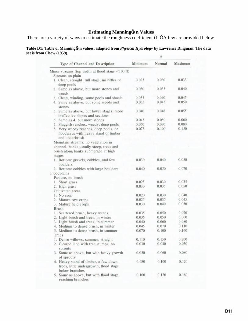
Estimating ManningÕ s n Values There are a variety of ways to estimate the roughness coefficient Ò n.Ó A few are provided below.
Table D1: Table of ManningÕ s n values, adapted from Physical Hydrology by Lawrence Dingman. The data set is from Chow (1959).
D11
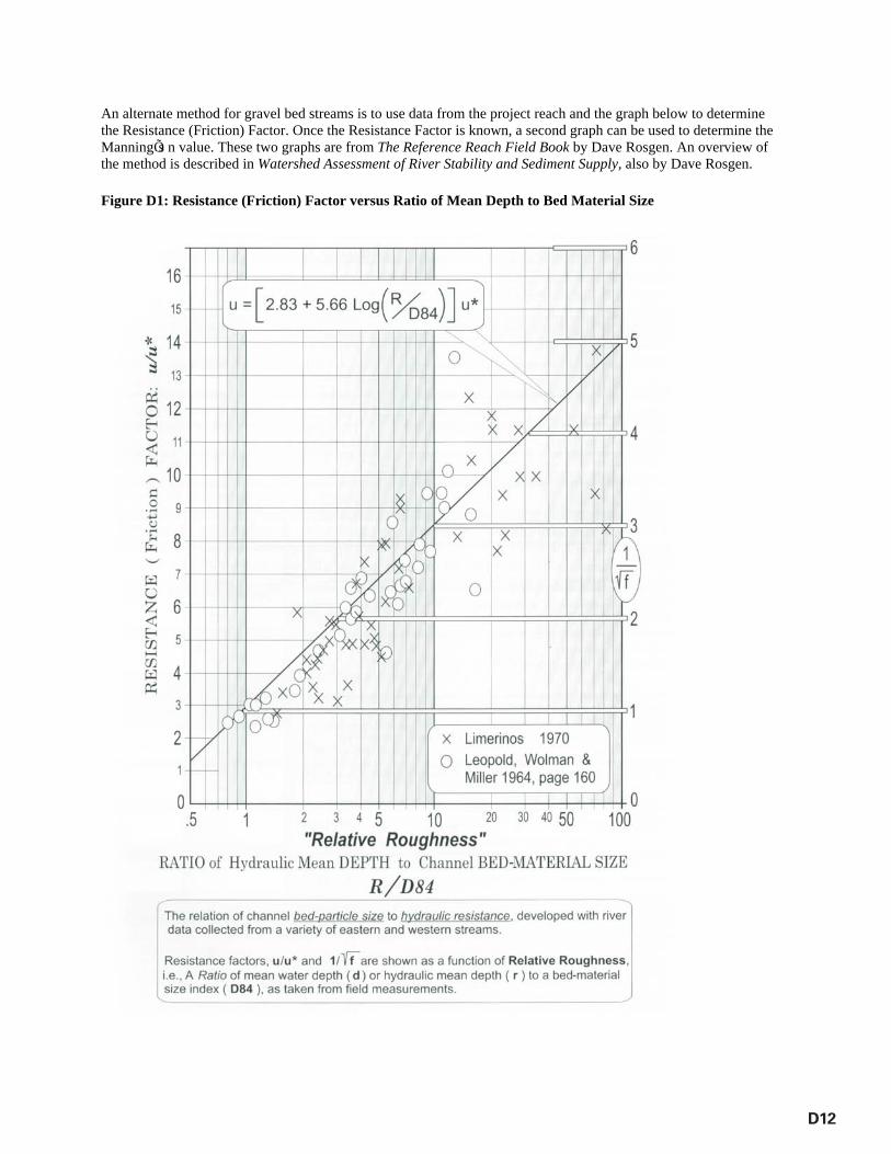
An alternate method for gravel bed streams is to use data from the project reach and the graph below to determine the Resistance (Friction) Factor. Once the Resistance Factor is known, a second graph can be used to determine the ManningÕ s n value. These two graphs are from The Reference Reach Field Book by Dave Rosgen. An overview of the method is described in Watershed Assessment of River Stability and Sediment Supply, also by Dave Rosgen. Figure D1: Resistance (Friction) Factor versus Ratio of Mean Depth to Bed Material Size
D12
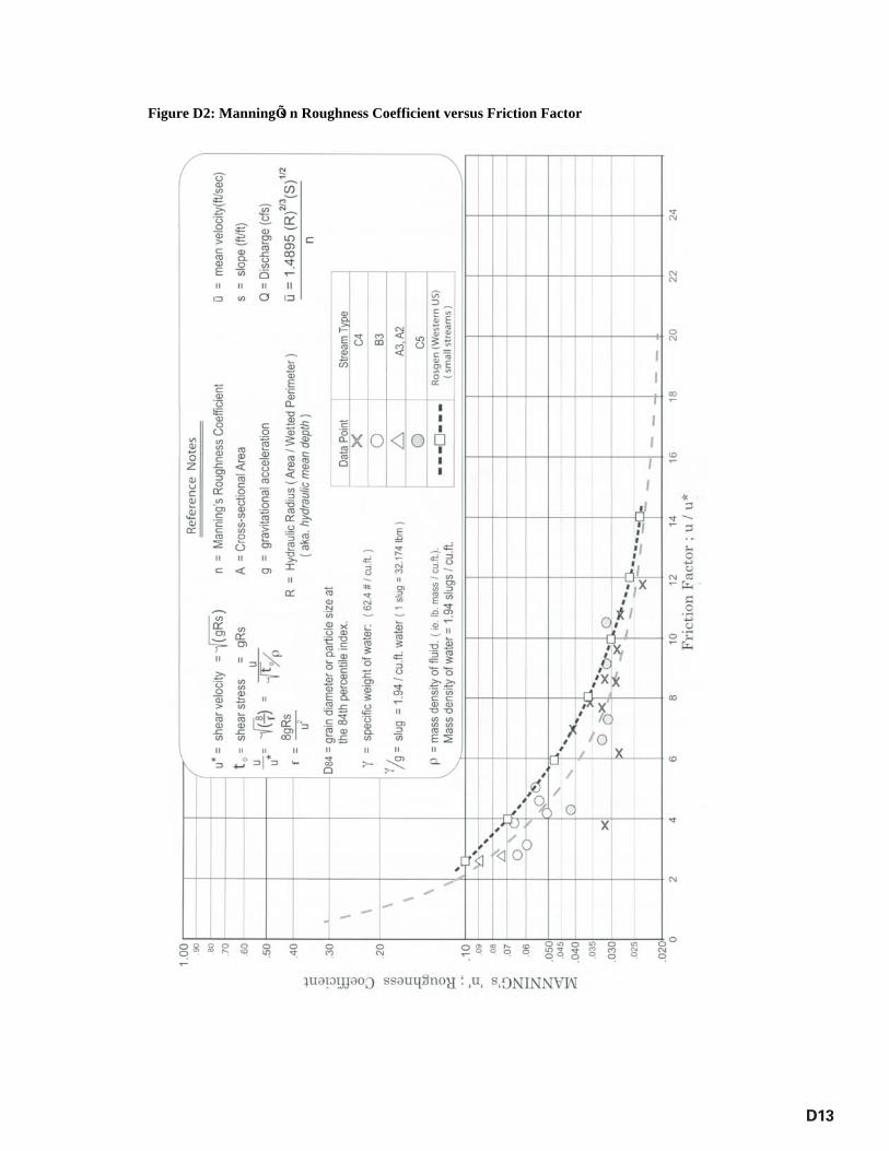
Figure D2: ManningÕ s n Roughness Coefficient versus Friction Factor
D13


E1
Appendix E Design Goals and Objectives
Definition of Goals and Objectives
Every stream restoration project, large or small, should have clearly stated goals. The goals should answer the question, “What is the purpose of this project?” Goals may be as specific as stabilizing an eroding streambank that is threatening a road, or as broad as creating functional lift to the maximum extent possible (based on a comparison to a reference condition). Unfortunately, it is common to see a goal that reads, “The purpose of this project is to restore channel dimension, pattern and profile so that the channel doesn’t aggrade or degrade over time.” The problem with this goal is that it fails to state why there is a need to change the channel geometry (dimension, pattern and profile). The goal should address a problem, which could be a stability issue, a functional issue or both. The Stream Functions Pyramid described below can be used as an aid in developing function-based goals.
Stream Functions Pyramid
The Stream Functions Pyramid, developed by Harman (2009), provides an approach that organizes stream functions in a pyramid form to illustrate that goal setting, stream assessment methodologies and stream restoration must address functions in a specific order. A broad-level view is shown in Figure E1. The functional categories have been modified from Fischenich (2006) to more closely match functions with parameters that are commonly used in the fields of hydrology, hydraulics, geomorphology, physicochemistry (called physicochemical on the pyramid) and biology. This helps the practitioner match the project goal with the corresponding stream functions to avoid the problems described by Fischenich (2006) and Somerville (2010), where practitioners design ineffective projects because they ignore the underlying hydrology, hydraulic and geomorphic functions. Through monitoring, these functions can then be used to determine the overall benefit of the stream restoration project by comparing the baseline functional value to the post restoration value, i.e., the functional lift.
Figure E2 shows a more detailed view of the Pyramid and includes parameters that can be used to describe the function in its corresponding category. These parameters can be structural measures or actual functions, meaning that they are expressed as a rate and relate to a stream process that helps create and maintain the character of the stream corridor. For example, within the Hydrology category, flood frequency is a parameter that can be used to quantify the occurrence of a given discharge. It is not a function, but it does provide critical information about the transport of water from the watershed to the channel, which is a function. Runoff is a parameter and a function (in the Hydrology category). It directly quantifies the amount of water that is being transported from the watershed to the channel, is expressed as a rate (often in cubic feet per second) and helps to define the character of the stream channel. However, the intent of the Pyramid is to use a variety of parameters (structural and/or functions) to describe the overall function of the category, in this case the transport of water from the watershed to the channel. If applied in this way, all parameters on the Pyramid can be thought of as function-based.

E2
Ultimately, the suite of parameters selected will be dependent on the project’s goals and budget, since some parameters can be measured quickly and inexpensively and others require long-term monitoring and expensive equipment.
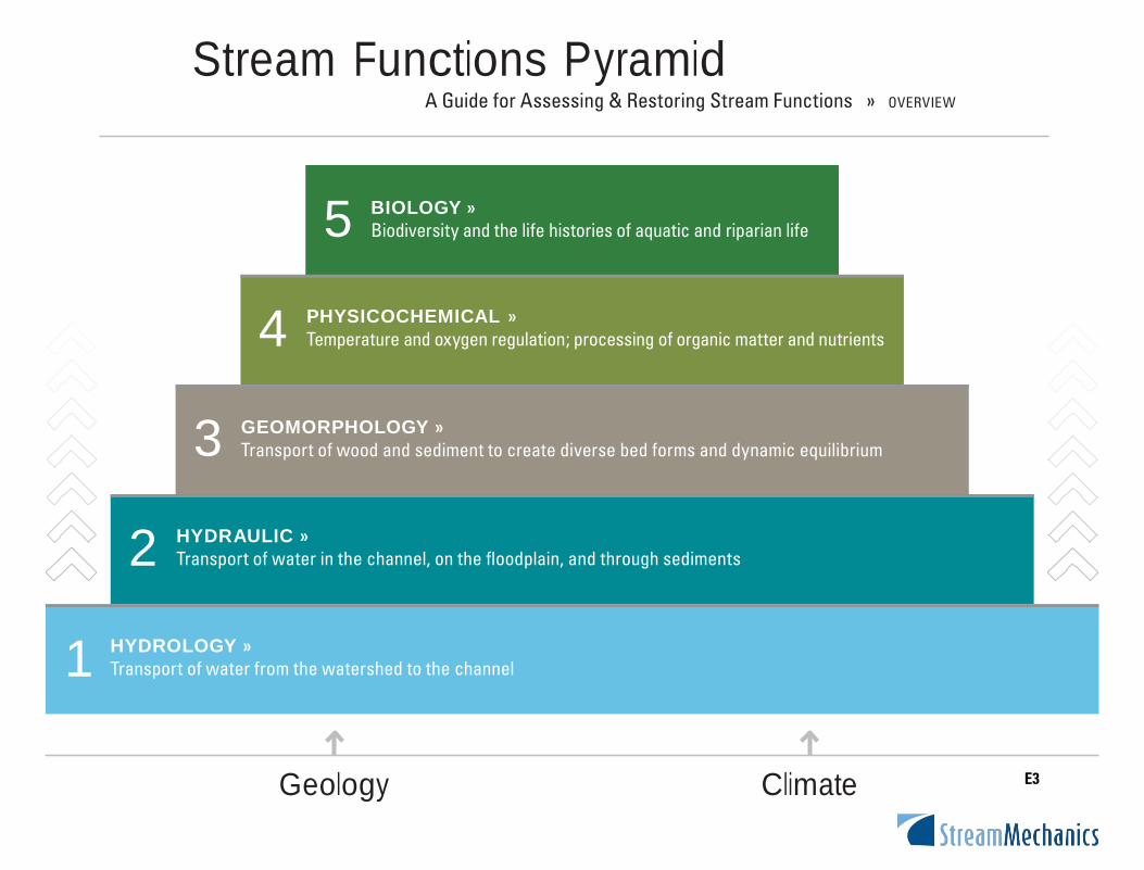
Stream Functions PyramidA Guide for Assessing & Restoring Stream Functions » OVERVIE W
Geology Climate
E3
5
4
3
2
1
BIOLOGY »Biodiversity and the life histories of aquatic and riparian life
PHYSICOCHEMICAL »Temperature and oxygen regulation; processing of organic matter and nutrients
GEOMORPHOLOGY »Transport of wood and sediment to create diverse bed forms and dynamic equilibrium
HYDRAULIC »Transport of water in the channel, on the floodplain, and through sediments
HYDROLOGY »Transport of water from the watershed to the channel
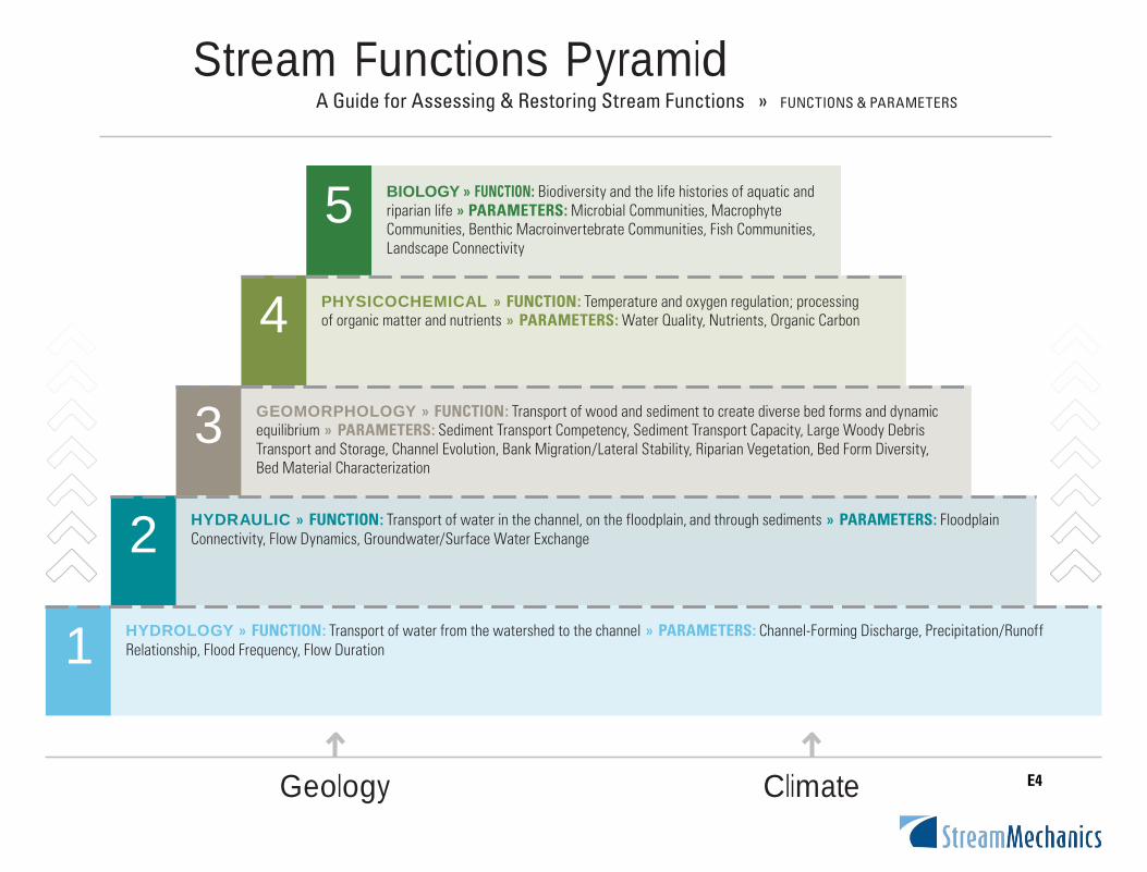
Stream Functions PyramidA Guide for Assessing & Restoring Stream Functions » FUNCTIONS & PAR AME TERS
Geology Climate
E4
5
4
3
2
1
BIOLOGY » FUNCTION : Biodiversity and the life histories of aquatic and riparian life » PARAMETERS: Microbial Communities, Macrophyte Communities, Benthic Macroinvertebrate Communities, Fish Communities, Landscape Connectivity
PHYSICOCHEMICAL » FUNCTION: Temperature and oxygen regulation; processing of organic matter and nutrients » PARAMETERS: Water Quality, Nutrients, Organic Carbon
GEOMORPHOLOGY » FUNCTION: Transport of wood and sediment to create diverse bed forms and dynamic equilibrium » PARAMETERS: Sediment Transport Competency, Sediment Transport Capacity, Large Woody Debris Transport and Storage, Channel Evolution, Bank Migration/Lateral Stability, Riparian Vegetation, Bed Form Diversity, Bed Material Characterization
HYDRAULIC » FUNCTION: Transport of water in the channel, on the floodplain, and through sediments » PARAMETERS: Floodplain Connectivity, Flow Dynamics, Groundwater/Surface Water Exchange
HYDROLOGY » FUNCTION: Transport of water from the watershed to the channel » PARAMETERS: Channel-Forming Discharge, Precipitation/Runoff Relationship, Flood Frequency, Flow Duration
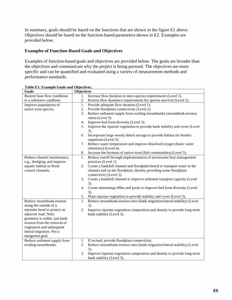
In summary, goals should be based on the functions that are shown in the figure E1 above. Objectives should be based on the function-based parameters shown in E2. Examples are provided below.
Examples of Function-Based Goals and Objectives
Examples of function-based goals and objectives are provided below. The goals are broader than the objectives and communicate why the project is being pursued. The objectives are more specific and can be quantified and evaluated using a variety of measurement methods and performance standards.
Table E1: Example Goals and Objectives. Goals Objectives Restore base flow conditions to a reference condition.
1. Increase flow duration to meet species requirements (Level 1). 2. Restore flow dynamics requirements for species survival (Level 2).
Improve populations of native trout species.
1. Provide adequate flow duration (Level 1). 2. Provide floodplain connectivity (Level 2). 3. Reduce sediment supply from eroding streambanks (streambank erosion
rates) (Level 3). 4. Improve bed form diversity (Level 3). 5. Improve the riparian vegetation to provide bank stability and cover (Level
3). 6. Incorporate large woody debris storage to provide habitat for benthic
organisms (Level 3). 7. Reduce water temperature and improve dissolved oxygen (basic water
chemistry) (Level 4). 8. Increase the biomass of native trout (fish communities) (Level 5).
Reduce channel maintenance, e.g., dredging, and improve aquatic habitat in flood control channels.
1. Reduce runoff through implementation of stormwater best management practices (Level 1).
2. Create a bankfull channel and floodplain bench to transport water in the channel and on the floodplain, thereby providing some floodplain connectivity (Level 2).
3. Create a bankfull channel to improve sediment transport capacity (Level 3).
4. Create alternating riffles and pools to improve bed form diversity (Level 3).
5. Plant riparian vegetation to provide stability and cover (Level 3). Reduce streambank erosion along the outside of a meander bend to protect an adjacent road. Note: geometry is stable, just bank erosion from the removal of vegetation and subsequent lateral migration. Not a mitigation goal.
1. Reduce streambank erosion rates (bank migration/lateral stability) (Level 3).
2. Improve riparian vegetation composition and density to provide long-term bank stability (Level 3).
Reduce sediment supply from eroding streambanks.
1. If incised, provide floodplain connectivity. 2. Reduce streambank erosion rates (bank migration/lateral stability) (Level
3). 3. Improve riparian vegetation composition and density to provide long-term
bank stability (Level 3).
E5

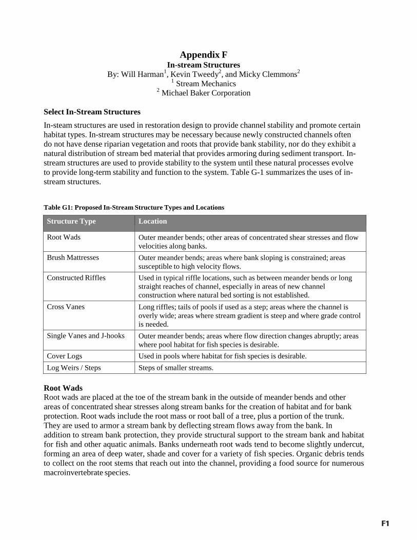
F1
Appendix F In-stream Structures
By: Will Harman1, Kevin Tweedy2, and Micky Clemmons2 1 Stream Mechanics
2 Michael Baker Corporation
Select In-Stream Structures
In-steam structures are used in restoration design to provide channel stability and promote certain habitat types. In-stream structures may be necessary because newly constructed channels often do not have dense riparian vegetation and roots that provide bank stability, nor do they exhibit a natural distribution of stream bed material that provides armoring during sediment transport. In-stream structures are used to provide stability to the system until these natural processes evolve to provide long-term stability and function to the system. Table G-1 summarizes the uses of in-stream structures.
Table G1: Proposed In-Stream Structure Types and Locations
Structure Type Location
Root Wads Outer meander bends; other areas of concentrated shear stresses and flow velocities along banks.
Brush Mattresses Outer meander bends; areas where bank sloping is constrained; areas susceptible to high velocity flows.
Constructed Riffles Used in typical riffle locations, such as between meander bends or long straight reaches of channel, especially in areas of new channel construction where natural bed sorting is not established.
Cross Vanes Long riffles; tails of pools if used as a step; areas where the channel is overly wide; areas where stream gradient is steep and where grade control is needed.
Single Vanes and J-hooks Outer meander bends; areas where flow direction changes abruptly; areas where pool habitat for fish species is desirable.
Cover Logs Used in pools where habitat for fish species is desirable. Log Weirs / Steps Steps of smaller streams.
Root Wads Root wads are placed at the toe of the stream bank in the outside of meander bends and other areas of concentrated shear stresses along stream banks for the creation of habitat and for bank protection. Root wads include the root mass or root ball of a tree, plus a portion of the trunk. They are used to armor a stream bank by deflecting stream flows away from the bank. In addition to stream bank protection, they provide structural support to the stream bank and habitat for fish and other aquatic animals. Banks underneath root wads tend to become slightly undercut, forming an area of deep water, shade and cover for a variety of fish species. Organic debris tends to collect on the root stems that reach out into the channel, providing a food source for numerous macroinvertebrate species.
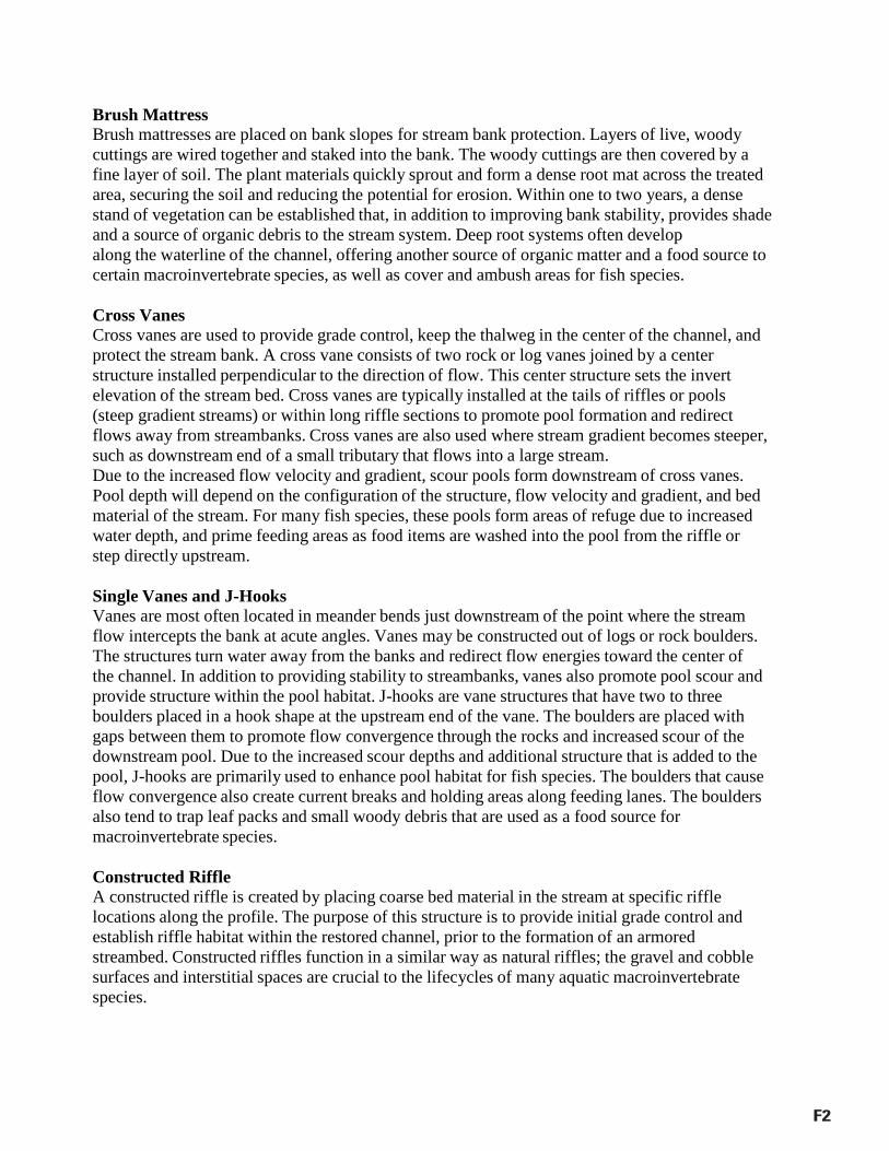
F2
Brush Mattress Brush mattresses are placed on bank slopes for stream bank protection. Layers of live, woody cuttings are wired together and staked into the bank. The woody cuttings are then covered by a fine layer of soil. The plant materials quickly sprout and form a dense root mat across the treated area, securing the soil and reducing the potential for erosion. Within one to two years, a dense stand of vegetation can be established that, in addition to improving bank stability, provides shade and a source of organic debris to the stream system. Deep root systems often develop along the waterline of the channel, offering another source of organic matter and a food source to certain macroinvertebrate species, as well as cover and ambush areas for fish species.
Cross Vanes Cross vanes are used to provide grade control, keep the thalweg in the center of the channel, and protect the stream bank. A cross vane consists of two rock or log vanes joined by a center structure installed perpendicular to the direction of flow. This center structure sets the invert elevation of the stream bed. Cross vanes are typically installed at the tails of riffles or pools (steep gradient streams) or within long riffle sections to promote pool formation and redirect flows away from streambanks. Cross vanes are also used where stream gradient becomes steeper, such as downstream end of a small tributary that flows into a large stream. Due to the increased flow velocity and gradient, scour pools form downstream of cross vanes. Pool depth will depend on the configuration of the structure, flow velocity and gradient, and bed material of the stream. For many fish species, these pools form areas of refuge due to increased water depth, and prime feeding areas as food items are washed into the pool from the riffle or step directly upstream.
Single Vanes and J-Hooks Vanes are most often located in meander bends just downstream of the point where the stream flow intercepts the bank at acute angles. Vanes may be constructed out of logs or rock boulders. The structures turn water away from the banks and redirect flow energies toward the center of the channel. In addition to providing stability to streambanks, vanes also promote pool scour and provide structure within the pool habitat. J-hooks are vane structures that have two to three boulders placed in a hook shape at the upstream end of the vane. The boulders are placed with gaps between them to promote flow convergence through the rocks and increased scour of the downstream pool. Due to the increased scour depths and additional structure that is added to the pool, J-hooks are primarily used to enhance pool habitat for fish species. The boulders that cause flow convergence also create current breaks and holding areas along feeding lanes. The boulders also tend to trap leaf packs and small woody debris that are used as a food source for macroinvertebrate species.
Constructed Riffle A constructed riffle is created by placing coarse bed material in the stream at specific riffle locations along the profile. The purpose of this structure is to provide initial grade control and establish riffle habitat within the restored channel, prior to the formation of an armored streambed. Constructed riffles function in a similar way as natural riffles; the gravel and cobble surfaces and interstitial spaces are crucial to the lifecycles of many aquatic macroinvertebrate species.

F3
Cover Logs A cover log is placed in the outside of a meander bend to provide cover and enhanced habitat in the pool area. The log is buried into the outside bank of the meander bend; the opposite end extends through the deepest part of the pool and may be buried in the inside of the meander bend, in the bottom of the point bar. The placement of the cover log near the bottom of the bank slope on the outside of the bend encourages scour in the pool, provides cover and ambush locations for fish species, and provides additional shade. Cover logs are often used in conjunction with other structures, such as vanes and root wads, to provide additional structure in the pool.
Log Weirs A log weir consists of a header log and a footer log placed in the bed of the stream channel, perpendicular or at an angle to stream flow, depending on the size of the stream. The logs extend into the stream banks on both sides of the structure to prevent erosion and bypassing of the structure. The logs are installed flush with the channel bottom upstream of the log. The footer log is placed to the depth of scour expected, to prevent the structure from being undermined. This weir structure creates a “step” – or abrupt drop in water surface elevation – that serves the same functions as a natural step created from bedrock or a log that has fallen into the stream. The weir typically forms a very deep pool just downstream, due to the scour energy of the water dropping over the step. Weirs are typically installed with a maximum height of 3 to 6 inches so that fish passage is not impaired. Log weirs provide bedform diversity, maintain channel profile, and provide pool and cover habitat.
Other Sources of In-Stream Structure Guidance
Rosgen, D.L. 2006. The Cross-Vane, W-Weir and J-Hook Vane Structures: Their Description, Design and Application for Stream Stabilization and River Restoration. Wildland Hydrology. Fort Collins, CO. http://www.wildlandhydrology.com/html/references_.html.

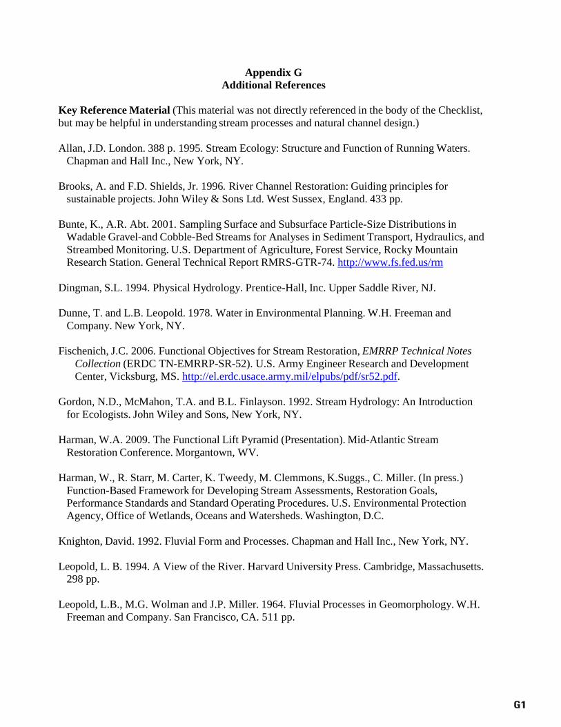
G1
Appendix G Additional References
Key Reference Material (This material was not directly referenced in the body of the Checklist, but may be helpful in understanding stream processes and natural channel design.)
Allan, J.D. London. 388 p. 1995. Stream Ecology: Structure and Function of Running Waters.
Chapman and Hall Inc., New York, NY. Brooks, A. and F.D. Shields, Jr. 1996. River Channel Restoration: Guiding principles for
sustainable projects. John Wiley & Sons Ltd. West Sussex, England. 433 pp. Bunte, K., A.R. Abt. 2001. Sampling Surface and Subsurface Particle-Size Distributions in
Wadable Gravel-and Cobble-Bed Streams for Analyses in Sediment Transport, Hydraulics, and Streambed Monitoring. U.S. Department of Agriculture, Forest Service, Rocky Mountain Research Station. General Technical Report RMRS-GTR-74. http://www.fs.fed.us/rm
Dingman, S.L. 1994. Physical Hydrology. Prentice-Hall, Inc. Upper Saddle River, NJ.
Dunne, T. and L.B. Leopold. 1978. Water in Environmental Planning. W.H. Freeman and
Company. New York, NY. Fischenich, J.C. 2006. Functional Objectives for Stream Restoration, EMRRP Technical Notes
Collection (ERDC TN-EMRRP-SR-52). U.S. Army Engineer Research and Development Center, Vicksburg, MS. http://el.erdc.usace.army.mil/elpubs/pdf/sr52.pdf.
Gordon, N.D., McMahon, T.A. and B.L. Finlayson. 1992. Stream Hydrology: An Introduction
for Ecologists. John Wiley and Sons, New York, NY. Harman, W.A. 2009. The Functional Lift Pyramid (Presentation). Mid-Atlantic Stream
Restoration Conference. Morgantown, WV. Harman, W., R. Starr, M. Carter, K. Tweedy, M. Clemmons, K.Suggs., C. Miller. (In press.)
Function-Based Framework for Developing Stream Assessments, Restoration Goals, Performance Standards and Standard Operating Procedures. U.S. Environmental Protection Agency, Office of Wetlands, Oceans and Watersheds. Washington, D.C.
Knighton, David. 1992. Fluvial Form and Processes. Chapman and Hall Inc., New York, NY.
Leopold, L. B. 1994. A View of the River. Harvard University Press. Cambridge, Massachusetts. 298 pp.
Leopold, L.B., M.G. Wolman and J.P. Miller. 1964. Fluvial Processes in Geomorphology. W.H.
Freeman and Company. San Francisco, CA. 511 pp.
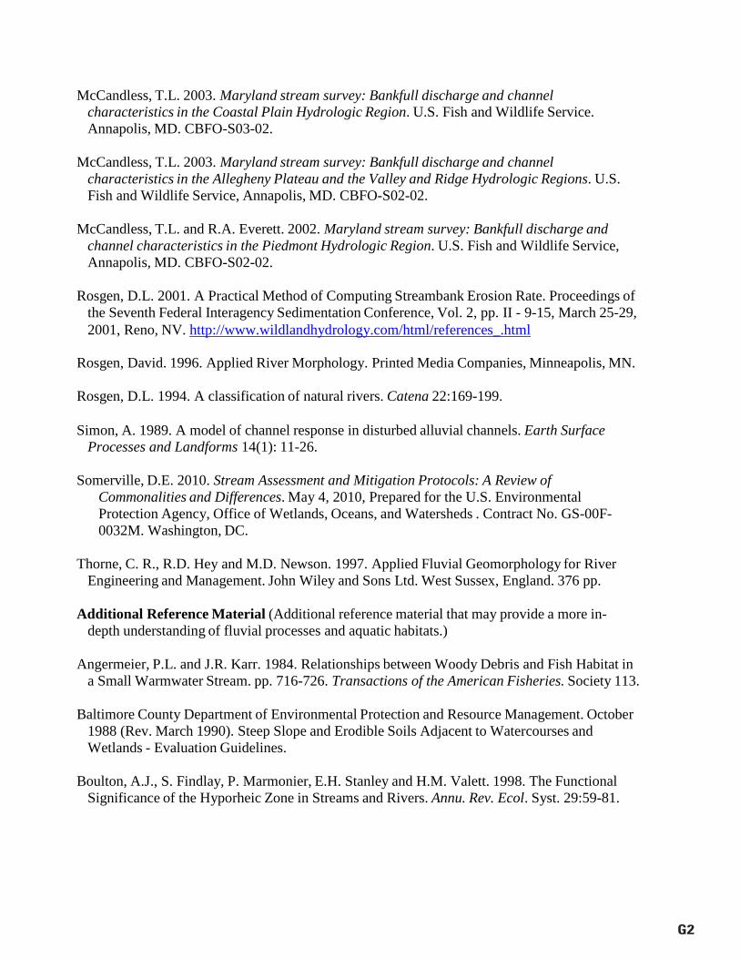
G2
McCandless, T.L. 2003. Maryland stream survey: Bankfull discharge and channel characteristics in the Coastal Plain Hydrologic Region. U.S. Fish and Wildlife Service. Annapolis, MD. CBFO-S03-02.
McCandless, T.L. 2003. Maryland stream survey: Bankfull discharge and channel
characteristics in the Allegheny Plateau and the Valley and Ridge Hydrologic Regions. U.S. Fish and Wildlife Service, Annapolis, MD. CBFO-S02-02.
McCandless, T.L. and R.A. Everett. 2002. Maryland stream survey: Bankfull discharge and
channel characteristics in the Piedmont Hydrologic Region. U.S. Fish and Wildlife Service, Annapolis, MD. CBFO-S02-02.
Rosgen, D.L. 2001. A Practical Method of Computing Streambank Erosion Rate. Proceedings of
the Seventh Federal Interagency Sedimentation Conference, Vol. 2, pp. II - 9-15, March 25-29, 2001, Reno, NV. http://www.wildlandhydrology.com/html/references_.html
Rosgen, David. 1996. Applied River Morphology. Printed Media Companies, Minneapolis, MN.
Rosgen, D.L. 1994. A classification of natural rivers. Catena 22:169-199.
Simon, A. 1989. A model of channel response in disturbed alluvial channels. Earth Surface Processes and Landforms 14(1): 11-26.
Somerville, D.E. 2010. Stream Assessment and Mitigation Protocols: A Review of
Commonalities and Differences. May 4, 2010, Prepared for the U.S. Environmental Protection Agency, Office of Wetlands, Oceans, and Watersheds . Contract No. GS-00F- 0032M. Washington, DC.
Thorne, C. R., R.D. Hey and M.D. Newson. 1997. Applied Fluvial Geomorphology for River
Engineering and Management. John Wiley and Sons Ltd. West Sussex, England. 376 pp. Additional Reference Material (Additional reference material that may provide a more in-
depth understanding of fluvial processes and aquatic habitats.) Angermeier, P.L. and J.R. Karr. 1984. Relationships between Woody Debris and Fish Habitat in
a Small Warmwater Stream. pp. 716-726. Transactions of the American Fisheries. Society 113. Baltimore County Department of Environmental Protection and Resource Management. October
1988 (Rev. March 1990). Steep Slope and Erodible Soils Adjacent to Watercourses and Wetlands - Evaluation Guidelines.
Boulton, A.J., S. Findlay, P. Marmonier, E.H. Stanley and H.M. Valett. 1998. The Functional
Significance of the Hyporheic Zone in Streams and Rivers. Annu. Rev. Ecol. Syst. 29:59-81.
G3
Baltimore County Department of Environmental Protection and Resource Management. January 1991. A Methodology for Evaluating Steep Slopes and Erodible Soils Adjacent to Watercourses and Wetlands.
Bren, L.J. 1993. Riparian Zone, Stream and Floodplain Issues: A Review. Journal of Hydrology
150:277-299. British Columbia. December 1996. Channel Assessment Procedure Guidebook. Forest Practices
CODE of British Columbia, Ministry of Forests. Victoria, B.C. Castelle, A.J., A.W. Johnson and C. Conolly. 1994. Wetland and Stream Buffer Size
Requirements - A Review. J. Environ. Qual. 23:878-882. Chesapeake Bay Program, Nutrient Subcommittee. EPA 903-R-95-004 CBP/TRS 134/95.
August 1995. Water Quality Functions of Riparian Forest Buffer Systems in the Chesapeake Bay Watershed. 58 pp.
Correll, D.L. 1997. Buffer zones and water quality protection: general principles. pp. 7-17.
Smithsonian Environmental Research Center, Edgewater, MD. Cummins, K.W. Structure and Function of Stream Ecosystems. November 1974. MI State Univ.,
Hickory Corners, MI. Gold, A.J. and D.Q. Kellogg. Modeling Internal Processes of Riparian Buffer Zones. Univ. of
RI, Kingston, RI. Gorman, O.T. and J.R. Karr. 1978. Habitat Structure and Stream Fish Communities. Purdue
Univ., West Lafayette, IN: Ecology 59(3). pp. 507-515. Groffman, P.M. 1997. Contaminant effects on microbial functions in riparian buffer zones.
Institute of Ecosystem Studies, Millbrook, NY. pp. 83-91. Gregory, K.J. 1987. River Channels, pp. 207-235 in Human Activity and Environmental
Processes, K.J. Gregory and D.E. Walling, eds. John Wiley and Sons, New York, NY.34 Hammer, T. R. 1972. Stream channel enlargement due to urbanization. Water Resources
Research 8: 1530-1540. Herrington, R.B. and D.K. Dunham. A Technique for Sampling General Fish Habitat
Characteristics of Streams. Intermountain Forest and Range Experiment Station, Ogden, UT. Hickin, E.J. 1984. Vegetation and River Channel Dynamics. Canadian Geographer, XXVII. pp.
111-126. Johnson, P.A., G.L. Gleason and R.D. Hey. June 1999. Rapid Assessment of Channel Stability in
Vicinity of Road Crossing. Journal of Hydraulic Engineering. pp. 645-651.
G4
Karr, J.R. Biological Integrity: A Long-Neglected Aspect of Water Resource Management. June
1990. Ecological Applications, 1(1). pp. 66-84. Karr, J.R. and I.J. Schlosser. July 1978. Water Resources and the Land-Water Interface. Science
Vol. 201. pp. 229-201. Kondolf G.M. and H. Piegay. 2003. Tools in Fluvial Geomorphology. Wiley. West Sussex,
England. Leopold, L.B. and T. Maddock, Jr. 1953. The hydraulic geometry of stream channels and some
physiographic implications. U.S. Geological Survey Professional Paper No. 252. 57 pp. Limerinos, J.T. 1970. Determination of Manning’s Coefficient from Measured Bed Roughness in
Natural Channels. U.S. Geological Survey Water Supply Paper 1898-B, Prepared in cooperation with the California Department of Water Resources, U.S. Government Printing Office, Washington, DC.
Lowrance, R., R. Leonard and J. Sheridan. Managing riparian ecosystems to control nonpoint
pollution. 1985. Journal of Soil and Water Conservation, Vol. 40, No. 1. pp. 87-91. Mid-Atlantic Coastal Streams Workgroup. July 1997. Field and Laboratory Methods for
Macroinvertebrate and Habitat Assessment of Low Gradient, Nontidal Streams. Ministry of Natural Resources. June 1994. Natural Channel systems - An Approach to
Management and Design. Ontario, Canada. Montgomery, D.R. and J.M. Buffington. June 24, 1993. Channel Classification, Prediction of
Channel Response, and Assessment of Channel Condition. Timber, Fish and Wildlife TFW- SH10-93-002.
Mulholland, P.J. 1992. Regulation of nutrient concentration in a temperate forest stream: Roles
of upland, riparian and instream processes. Limnol. Oceanogr. 37(7). pp. 1512-1526. Myers, L.H. July 1989. Riparian Area Management. Bureau of Land Management Service
Center Technical Reference 1737-3, Denver, CO. Naiman, R.J. and H. Décamps. 1997. The Ecology of Interfaces: Riparian Zones. Annual Rev.
Ecol. Syst. 28. pp. 621-58. North Carolina Division of Water Quality, 401/Wetlands Unit. May 2000. Benthic
Macroinvertebrate Monitoring Protocols for Compensatory Stream Restoration Projects. Interim, Internal Technical Guide.
G5
Wilcock, P.R. Sediment Transport in the Restoration of Gravel-bed Rivers. Dept. of Geography and Environmental Engineering, John Hopkins University, Baltimore, MD. https://jshare.johnshopkins.edu/pwilcoc1/public_html/5.%20SedTransInStreamRestoration.pdf
Useful Websites for Additional Reference Material NCSU Stream Restoration Program http://www.bae.ncsu.edu/programs/extension/wqg/srp/
University of Louisville Stream Institute https://louisville.edu/speed/civil/si
NRCS Website. Regional Hydraulic Geometry Curves. Provides links to various regional curve websites. http://www.nrcs.usda.gov/wps/portal/nrcs/main/national/home
Ohio Department of Natural Resources: Stream morphology spreadsheets http://www.dnr.state.oh.us/soilandwater/water/streammorphology/default/tabid/9188/Default.aspx
Ohio State University: STREAMS Webpage http://streams.osu.edu/
River Rat: Restoration Analysis Tool http://www.restorationreview.com/
Stream Mechanics http://stream-mechanics.com/
U.S. EPA Stream Mitigation Webpage http://water.epa.gov/lawsregs/guidance/wetlands/wetlandsmitigation_index.cfm
U.S. Fish and Wildlife Services, Chesapeake Bay Field Office http://www.fws.gov/chesapeakebay/streampub.html
USFS Stream Team Webpage for Stream Notes Newsletter http://www.stream.fs.fed.us/news/index.html
Wildland Hydrology Reference Materials http://www.wildlandhydrology.com/html/references_.html