refurbishment by steelwork - arcelormittalds.arcelormittal.com/repo/brochures/refurbishment by...
TRANSCRIPT
Refurbishment by steelwork
Long Carbon EuropeSections and Merchant Bars

Combined use of new and existing materials encourages architectural diversity

Contents
1. Introduction 2
2. Steel work versus consolidation levels 10
3. Refurbishment of masonry and wooden structures 26
4. Refurbishment of reinforced concrete (R.C.) structures 38
5. Refurbishment of iron/steel structures 44
6. Seismic upgrading 54
7. Additions 68
Technical assistance & Finishing 78
Your partners 79
1


33
1. INTRODUCTION 1.1 General 41.2 Operational aspects 51.3 Advantages of steel in refurbishment 61.4 Restoration prerequisites 71.5 Application fields 8

Old masonry buildings often suffer damage as a result of age and the ravages of time and therefore require structural consolidation and functional rehabilitation. In addition, more modern buildings made of reinforced concrete require frequent refurbishment due to their poor state of preservation.
In order to preserve and protect existing constructions, many consolidation and restoration systems have been used in recent decades. Steelwork plays an important role in such activity.
The restoration and consolidation processes, particularly with regards to more delicate structural restoration of monuments, require very careful selection of new construction materials. These must be chosen according to the prerequisites of the materials to be consolidated.
1.1 General
The refurbishment of existing buildings and bridges is nowadays an emerging activity. Since the 1970s, we observe that the building industry become more and more focused on the following activities: consolidation, rehabilitation and modernisation of old buildings.
1. Introduction

5
Distinction may be made between new materials which represent the “remedy” and old materials representing the “sick”. As a “remedy” we may use traditional materials: cement, mortar, reinforced concrete or steel. We may also use innovative materials: special mortars, fibre reinforced polymers (FRP), special metals (high strength steels, stainless steel, etc) or even some special devices belonging to advanced systems of seismic protection which use passive control technologies.
The problem, therefore, may be analysed using a matrix, where all remedial materials (materials for consolidation) and “sick” materials (belonging to damaged structures) are listed, giving rise to new composite materials.
The selection of the most appropriate combination, over all those offered by this matrix, represents the main goal of structural consolidation. It appears that steelwork always represents a “remedy” for all “sick” materials.
From a general overview of the possible consolidation systems, we may recognise that:
l Consolidation systems based on cement and concrete materials are widely used, especially in seismic upgrading operations, These are in the form of injections and/or reinforced concrete (r.c.) elements, but their compatibility with the masonry of old architectonic constructions is questionable and it is particularly worth noting that they are not reversible;
l Consolidation systems based on polymeric and composite materials are very recent and, at least for the moment there is insufficient evidence to validate their durability; their reversibility is also questionable;
l Consolidation systems based on steelwork are widely and successfully used in both cases of monumental constructions and for standard buildings made of masonry and r.c.;
l The use of special devices is currently in its early stages, but promises to become a more widely used application in the future.
From a structural point of view, the analysis of several practical examples collected from all over the world demonstrates that appropriate selection of steelwork allows to fulfil the complex requirements arising at the various stages of the consolidation of damaged structures. In addition, in the case of architectural constructions, steelwork satisfies the strict conditions imposed by restoration principles.
DA
MA
GED
ST
RUCT
URE
S
NEW COMPOSITE MATERIALS - Materials for consolidation
STEEL CONCRETE MASONRY WOOD FRP
STEEL ++ +
CONCRETE ++ + +
MASONRY ++ + + + +
WOOD ++ + +
1.2 Operational Aspects 1. Introduction

The use of steelwork in consolidation and structural restoration operations takes advantage of the following peculiar features:
l Prefabrication allows the execution of the main elements by welding in the workshop. They are tailor-made according to the transportation and operational needs in the construction yard. They may be easily connected by bolting;
l Reversibility is a basic property of steelwork, thanks to the use of bolted connections. It is not applicable only for provisional but also for permanent constructions (Figure 1.3.1);
l Lightness of structural elements, due to the high strength-to-weight ratio. Transportation and erection phases are simplified and the increase of loads is minimized;
l Reduced dimensions of the structural elements are a natural consequence of the high structural effectiveness of steel. The substitution and/or the integration of the existing works with new reinforcing elements is simplified;
l Aesthetical appearance of steel elements is fundamental when the structural synergy between old and new materials is coupled. The architectural value takes advantage of their contrasting features (Figure 1.3.2);
l Speed of erection is ideal in any case, but particularly when the intervention of rehabilitation is very urgent. It prevents further degradation and guarantee an immediate safeguard;
l The possibility of finding a variety of steel products on the market is important in order to satisfy all design and erection needs with a large degree of flexibility. A wide range of products is available: from hot rolled sections in the form of plates, double T, channels, angles to prefabricated elements like cellular beams, slim floor beams, trapezoidal sheeting and so on.
All of the abovementioned features confirm steelwork as the most suitable material for consolidating structural elements made of masonry, r.c., timber and, of course, iron/steel itself.
1.3.2
1.3.1
1.3 Advantages of steel in refurbishment
1. Introduction
1.3.2

When the building to be consolidated is of historic interest, its restoration is a very delicate process. The restoration criteria are oriented towards the conservation of pre-existing buildings. The integration of new works has to ensure their return to functionality. Such new works must be clearly modern in appearance; they must be distinguishable and they must be reversible, through use of technologies and materials which may be removed without damaging the existing structure.
The various international restoration “Charts”, in fact, state the incongruity of reconstruction in using the methods of the past, which may no longer be reproduced for many reasons, above all technological. Other reasons are related to nostalgia for traditional construction methods, tools and materials, new functional requirements and lack of availability of old materials. At the same time these “Charts”, especially in cases where the restoration operation involves restructuring with partial reconstruction, indicate the need to use well-adapted technologies and materials in a clearly modern way.In particular, the Chart of Venice (1964)
states that the integration works must be characterized by the “feature of our age” and, “when the traditional techniques are ineffective, the consolidation of a monument must be assured by using all the most modern tools for structure and conservation, whose effectiveness is demonstrated by scientific data and guaranteed by the experience”.
A logical application of these principles undoubtedly shows that steel, as a material and its technology, has the advantage of being a modern material with “reversible” characteristics. It is particularly suited to reconcile with the materials of the past and to form integrated structural systems. In addition, its choice is substantially based on its high mechanical performance and on the flexibility of the constructional systems.
Construction systems based on other materials (cement, mortar, concrete, polymeric, composite) do not fulfil the above important prerequisite of reversibility.
In conclusion, the use of structural steel in the rehabilitation of old monumental buildings is perfectly in line with the recommended criteria of the modern theory of restoration. Steel is therefore widely used in restoration works in all kinds of ancient monuments and historic buildings, also under form of special devices for seismic protection.
1.3.1 The use of bolted connection is an important pre-requisite for the “reversibility” of the solution1.3.2 The aesthetic value of a synergetic contrast between old and new materials
1.4 Restoration prerequisites
7
1. Introduction

Several examples of refurbishment, rehabilitation and extension using steelwork may be found all over the world.
l Old industrial constructions have been converted into apartments or offices (Figure 1.5.1).
l Historic buildings have been entirely gutted, keeping the original façades and replacing the interior with a new skeleton (Figure 1.5.2).
1.5 Application fields
1.5.1
1. Introduction
Self-supporting structures have been inserted into historic monuments and provide a suitable integration with modern stylistic values. This kind of application is becoming more and more common for museums and exhibition halls.

l Many ancient churches have been covered by steel roofing systems, composed of trusses and trapezoidal sheets (Figure 1.5.3). Other important buildings have been restructured using vertical and horizontal extensions, which are harmonised both from structural and aesthetic points of view.
l Entire districts of old towns in Italy have been completely restored after suffering serious damage from recent earthquakes; steel components have been used in order to improve the seismic resistance of old masonry buildings.
l Reinforced concrete structures have been repaired by means of steel elements after being damaged or when heavier serviceability conditions are required. They have also been transformed by changing the structural scheme from the original, when a reduction or an increase in the storey height is carried out or when steel bracings are introduced for seismic upgrading purposes.
1.5.1 Old industrial steel structure is transformed into apartment building (Paris, rue de l’Ourcq)1.5.2 A new steel skeleton inside of the existing masonry façades (“Kannerland” in Luxembourg)1.5.3 The new steel roof of a church (Salerno, Italy)
1.5.3
1.5.2
1. Introduction
9
+ 14.13 m
+ 11.28 m
+ 7.75 m
+ 3.97 m
+ 0.00 m


1111
2. STEEL WORK VERSUS CONSOLIDATION LEVELS2.1 General 122.2 Safeguard 122.3 Repairing 162.4 Reinforcement 182.5 Restructuring 20

Safeguarding is the first level of consolidation of existing buildings. It consists of a set of provisional steps that are able to assure adequate safety for both the public and the site during the transitory phase preceding any definitive consolidation operations (Figure 2.2.1). This provision is used both for protecting the site and to prevent partial or total collapse of the building when structurally unsafe buildings require urgent steps to make them safe.
The requested characteristics of the safeguarding systems are:
l speed of execution
l flexibility of the constructive systems
l adaptability for narrow and work areas which are difficult to access
l reversibility of restoration work.
The main fields of application are the following:
l temporary support of façades during the reconstruction of a new building between two existing ones, by means of reticular space trusses
l steelwork structure which supports the façade during the demolition of the internal part of the building (gutting operation); the supporting function may be temporary or part of the final structure (i.e. vertical trusses to stiffen the façade)
l temporary support of building façades immediately following an earthquake, by using steel scaffoldings which avoids the need to block access to a street
l temporary roofing to provide adequate protection of the site area from the bad weather during restoration (Figure 2.2.2).
2.2.1 Steelwork as provisional system for keeping an old façade standing (Montreal, Canada)2.2.2 A provisional roof for protecting the site during restoration operations (Athens, Greece)
2.1 General
A distinction may be made between the different requested levels of consolidation. It is directly related to the quality of the steps and, sometimes, also to the chronological order in which the consolidation steps have to proceed. The proposed classification considers four levels: safeguarding, repairing, reinforcing and restructuring.
2.2 Safeguarding
2.2.1
2.2.2

13
Chamber of Commerce, Luxembourg
13

2. Steel work versus consolidation levels
2.2.3 Provisional intervention to the tympanum of the San Francisco church in Assisi (Italy)2.2.4 Temporary steelwork to sustain the façade of a building after a fire (Lisbon, Portugal)
During the application of safeguarding operations, steelwork is mainly used in the following ways:
l structural steel elements, in the form of “scaffolding systems”, offer
ad hoc solutions designed to achieve optimum results and tailored to specific requirements (Figure 2.2.3)
l heavy steel structures (welded or bolted profiles) and light ones (hollow sections with bolted joints) are effectively adopted in safeguarding active and passive operations (Figures 2.2.4 and 2.2.5).
2.2.4
2.2.3The above structural steel systems provide the following advantages:
l light-weight
l high prefabrication
l ease of transport and erection
l economic convenience, due to their possibility of re-use.

15
2.2.5 Temporary support for the columns of the entrance of Carigliano Palace in Turin (Italy)
2.2.5
2. Steel work versus consolidation levels

l Speed of erection, useful when emergency repairs must be made as there is a risk of the damage quickly progressing (Figure 2.3.2)
l economic convenience, thanks to the potential of re-use (Figure 2.3.3).
2.3.1 Steel angles and ties for repairing a r.c. column2.3.2 Steel portal frames for repairing stone architraves (Berlin, Germany)2.3.3 Expo church in Hanover: modular steel structure in view of a future dismantling and reconstruction in another location
Steel structural elements offer, by means of “prefabricated” types of technology, ad hoc solutions designed to achieve optimum results and tailored to specific requirements.
Prerequisites of the steelwork components are:
l light-weight composition, allowing ease of transport and erection. They are important factors when it is necessary to work in areas where space is restricted such as historic centres of old towns
l reversibility, thanks to the use of bolted joints, which allows the re-use of the structure in case of dismantling (Figure 2.3.1)
Repair is the second level of consolidation of existing buildings. It involves a series of operations carried out on the building to restore its former structural efficiency before its damage. Repair, different to safeguarding, represents a definitive operation used where well identified damage was caused over a long period of time and therefore, do not require urgent intervention. It provides straightforward restoration of the structural performance, which meet minimum safety requirements. It is done without introducing any additional strengthening in building structures damaged by the weather and ravages of time.
As part of the repair stage, there are numerous technological consolidation systems based on the use of steelwork. They can improve the structural behaviour of masonry, reinforced concrete as well as timber building structures.
2.3 Repair
2.3.1 2.3.2 2.3.3
2. Steel work versus consolidation levels

17
Dames de France, Perpignan, France

2. Steel work versus consolidation levels
Reinforcement involves improving the structural performance in order to enable the building to meet new functional or environmental requirements. This consolidation level does not significantly affect the structural scheme. New elements are integrating the existing ones without substantially altering either the mass or the stiffness distribution of the building.
Contrary to simple reparation, reinforcement may be carried out at various levels according to the different increases of strength required. Previous level of damage has to be considered when it exists.
From a seismic point of view, the strengthening operation may be distinguished on two levels: simple improvement and upgrading.
2.4 Reinforcement
2.4.1
Upgrading is carried out in order to ensure a higher degree of safety. In this case the reinforcement work acts either on a single part or the overall structure without excessively modifying its static scheme and, therefore, the global behaviour. Improvement work may also be carried out on single structural elements when they are affected by design errors or bad execution.
Seismic upgrading work is characterised by a set of necessary steps required to ensure that the structure is able to withstand new earthquake design loads. It may also require extensive revision of the structural system, with complete modification of the global seismic performance. In this case, this intervention has to be classified from the structural point of view within the restructuring operations.

19
The different levels of reinforcement, from simple improvement to upgrading, may be carried out through use of the same technological consolidation systems as those used for repairing. Steelwork is commonly used to improve the static behaviour of both masonry and reinforced concrete buildings. Bracing systems are often used for seismic upgrading of both masonry and reinforced concrete structures. Innovative bracing systems are based on the use of steel eccentric bracing (EB) (Figure 2.4.1), steel buckling restrained bracing (BRB) (Figure 2.4.2), and low-yield steel stiffened panels (Figure 2.4.3).
Reinforcing work is required when:
l buildings are subjected to heavier loading conditions, due to a change of use that requires an increase of service loads
l existing constructions are located in an area recently included in a new seismic zone, and are therefore subjected to more severe loading conditions due to the risk of earthquakes.
National regulations usually make a clear distinction between simple improvement and seismic upgrading works. The improvement work may be adapted in the following cases:
l when variation of the intended use occurs
l when design and/or execution defects must be eliminated
l when the consolidation operations are applied to monumental buildings, that are unsuitable for extensive work.
Seismic upgrading is compulsory in the following cases:
l super elevation or extension of the construction, with an increase in volume and areas
l increase of loads due to a change in the intended use
l substantial modification of the structural system following renovation in comparison with the original or, in general, when the global behaviour is affected during restructuring .
2.4.3
2.4.2
2.4.1 R.C. structure upgraded by eccentric steel braces2.4.2 R.C. structure upgraded by steel BRB (buckling restrained brace)2.4.3 R.C. structure upgraded by steel panels
2. Steel work versus consolidation levels

2. Steel work versus consolidation levels
Restructuring represents, in hierarchical order, the more general consolidation level of existing buildings. It consists of the partial or total modification of the functional distribution, layout and volumetric dimensions. It is accompagnied with a change of the original features of the building, including the structural system. There are four different kinds of restructuring work: gutting, insertion, addition and lightening.
l Gutting is the total or partial replacement of the internal part of a building with a new and different type of structure. This is carried out when architectural and/or town-planning reasons require the complete conservation of the building façades, whilst the interior layout is changed for functional reasons (Figures 2.5.1 a,b).
2.5 Restructuring
2.5.1a
2.5.1 The old “Römerhof” in Zurich is now a modern bank: a) the façade; b) the new offices of the “Römerhof” are located in a steel structure inside the existing façade2.5.2 Examples of insertion in a masonry building: a) a new steel mezzanine; b) a new steel staircase2.5.3 Steel floor in an office building in Luxembourg
2.5.1b

21
l Insertion represents the introduction of new structures or structural elements into the existing volumetric dimension. Additional intermediate floors or mezzanines are created in order to increase the usable area within the limits of a given volume (Figures 2.5.2 a, b). An example of insertion work is the addition of large amount of self-supporting frames to house special exhibition showcases visible from several floors, staircases and lift cages (Figure 2.5.3).
2.5.2b
2.5.2a
2.5.3
2. Steel work versus consolidation levels

2. Steel work versus consolidation levels
l Addition is carried out for new functional requirements, involving the increase of the original volume of the building, which may be extended horizontally or vertically.
- Horizontal addition consists of the introduction of new lateral volumes alongside the original structure. In these cases, aesthetic, more than structural aspects, play a greater role due to the necessity of harmonize different architectural styles (Figures 2.5.4 and 2.5.5).
2.5.4a
2.5.5
2.5.4 A new steel building in the industrial archaeology area of Catania (Italy), called “Le Ciminiere”, where the old masonry buildings have been restored with a steelwork2.5.5 A new steel building inside historical buildings in the city centre of Udine (Italy)
2.5.4b

23
Abbey of Neumünster, Luxembourg

Exhibition hall in Cologne, Germany

25
- Vertical addition requires the extension of the height of the building by one or more storeys above the existing structure. Depending on the amount of additional weight, it may be necessary to re-check the load-bearing capacity of the original structure. Some consolidation work may have to be done prior to this addition. This problem is particularly significant in areas of seismic activity, where the overall behaviour of the building is strongly influenced by the addition of new masses particularly on the upper levels. The need to minimize the additional structural weight makes steel the most suitable material, thanks to its high strength/low weight ratio (Figures 2.5.6 a, b).
l Lightening, as opposed to vertical addition, may include the removal of one or more of the upper floors due to the need to reduce the level of stresses in the structure. This scope may be achieved by means of steps involving the replacement of the original floors, roofs or other structural elements with new lighter materials. The replacement of heavy wooden floors with light steel I-section and corrugated steel sheets as well as the consolidation of old roofs with steel trusses is very common.
Restructuring is appropriate when the modification of the functional layout of a building requires the introduction of new volumes and areas or when new regulations requires the modification of the resistant structural system. This is also necessary
2.5.6a 2.5.6b
for extensively damaged buildings which require the complete modification and the upgrading of the structural system.
Conservation of existing buildings and their integration with new clearly distinguishable and reversible work represents a classical restructuring operation, which must be based on the modern theory of restoration.
A logical application of the restoration principles undoubtedly shows that steel and its technology have the necessary prerequisites of a modern material with “reversible” characteristics. It is particularly suited to be used alongside traditional materials, thus forming an integrated structural system.
2.5.6 a) A steel super elevation of an old masonry mill in Briatico (Calabria, Italy), now a sporting club; b) details of the new steel structure at the second floor
2. Steel work versus consolidation levels


2727
3. REFURBISHMENT OF MASONRY AND WOODEN STRUCTURES3.1 Consolidation of masonry structures 283.2 Masonry building consolidation 303.3 Masonry building degutting in Paris (France) 313.4 Consolidation of wooden structures with steel elements 323.5 Replacement of wooden trusses by steel trusses 343.6 Roofs made of steel and glass 37

3. Refurbishment of masonry and wooden structures
“The load-bearing capacity of masonry elements must be improved when damages caused by external unexpected loads occured (i.e. earthquake) or when the whole structure must be upgraded to resist to higher loading conditions imposed by a new use of the building.”
3.1 Consolidation of masonry structures
A classic system for improving the load-carrying capacity of masonry elements consists of injections of pressurised mortar or cement, combined or not with anchor steel bars. If it is the case the use of stainless steel is advisable in order to avoid future damage caused by corrosion. However this system is not reversible and is therefore contrary to the basic principle of restoration.
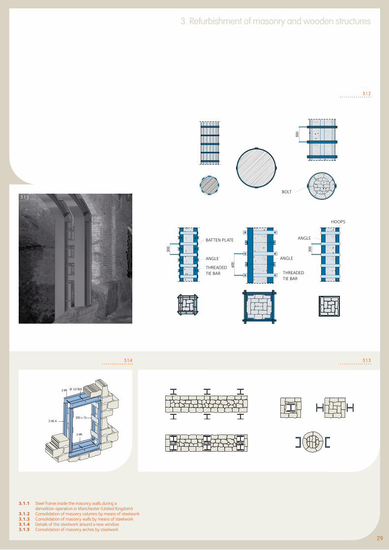
By observing some old masonry buildings during demolition, it is evident that steel frames were originally used for reinforcing the masonry itself (Figure 3.1.1). This means that steelwork represents the most suitable system of consolidation.
Damaged masonry columns, are usually repaired by means of steel hoops. The lateral restraining of the material produces a significant increase of the vertical load-bearing capacity (Figure 3.1.2).
In the case of circular columns, the hoops may be made of vertical plates with rectangular cross-sections, which are reinforced by horizontal steel rings. In the past, the prestressing operation was made by heating and the subsequent contraction of the rings. Nowadays, two half rings may be prestressed with bolts (Figure 3.1.2).
In the case of square or rectangular cross-sections, angle shapes may be used as vertical elements in the corners. They may be connected
in different ways: by means of internal ties integrated by batten plates, by means of channels connected by external ties or by means of horizontal rings (Figure 3.1.2).
When it is necessary to transfer a significant proportion of the total vertical load from the masonry panel to a new steel structure, the new steel columns may be inserted into proper grooves or simply connected to the masonry (Figure 3.1.3).
In case of openings, the strength of the missing part of masonry may be recovered with steel beams on the upper part or steel frames around the opening (Figure 3.1.4). Also masonry arches may be reinforced by means of steelworks (Figure 3.1.5).
3.1.1
29
3. Refurbishment of masonry and wooden structures
29
3.1.1 Steel frame inside the masonry walls during a demolition operation in Manchester (United Kingdom)3.1.2 Consolidation of masonry columns by means of steelwork3.1.3 Consolidation of masonry walls by means of steelwork3.1.4 Details of the steelwork around a new window3.1.5 Consolidation of masonry arches by steelwork
3.1.5
BATTEN PLATE
BOLT
ANGLE
THREADEDTIE BAR
ANGLE
THREADEDTIE BAR
ANGLE
HOOPS
3.1.2
3.1.33.1.4

3. Refurbishment of masonry and wooden structures 3.2 Masonry building consolidation: the re-use of a building complex in Bologna (Italy)
A large building complex in Bologna has been completely transformed and is now multipurpose, containing a hotel, apartments and shops. Steelwork has been selected both for structural and architectural reasons.
The 5- to 6-storey masonry buildings around the perimeter have been consolidated by keeping their original feature. Some buildings in the central part, seriously damaged, were demolished and replaced by three new 2- to 3-storey buildings. Moment-resisting steel frames were inserted in both directions.
The insertion of two levels of steel frames with independent foundations inside the existing masonry allowed to build a series of stairs and walkways at the two levels below and around the internal court. These new frames are made of HE sections. The erection process of the inserted steel elements and the subsequent demolition of the masonry were carried out without any safeguarding works.
The internal court is characterised by a number of steel staircases (Figure 3.2.1) connecting the first floor.
3.2.1 Detail of staircases in the internal court of the building block in Bologna (Italy)
3.2.1

31
3. Refurbishment of masonry and wooden structures
31
3.3 Gutting of masonry building and insertion of a new steel structure (Paris, France)
3.3.1
Some important buildings in Paris have recently been refurbished through gutting. Two buildings in boulevard Haussman at numbers 6-8 and 54 have been completely emptied and a new steel structure inserted into the existing façades (Figure 3.3.1).
The AGF building at Ilot Lafayette has been renovated by extensive use of castellated steel beams. Another building in place d’Iéna 7 has been gutted and a new 8-storey steel structure erected inside.
A group of buildings, built between the beginning of the 20 th Century and the 1950s, has been renovated and converted into a unique modern office building - called “Le Centorial” – with a new parking area in the basement. In much of the above work, both principal and secondary beams of the floor structures are castellated, in order to allow straightforward installation of technological equipments.
3.3.1 Restoration of the AGF building in Paris (France)

3. Refurbishment of masonry and wooden structures 3.4 Consolidation of wooden structures with steel elements
3.4.3b
3.4.3aMasonry buildings are usually integrated by floor structures made of timber. It is very often necessary to strengthen the timber parts (beams and deck) as they are usually in a poor state of conservation due to wood fungus, parasites and maceration.
Many systems have been proposed to improve the load-carrying capacity of beams. There are two main ways of doing this depending on whether it is convenient to work from underneath or from above the beams in order to insert additional steel elements (Figures 3.4.1 a, b).
In the first case, steel reinforcements may be added in different forms underneath, from simple plates to hot-rolled H or U sections, which may be adapted to individual cases according to the feature of the structure to be consolidated.
When the original shape of the beam must be preserved because it is of particular historical interest, it is necessary to implement the second method, namely by working from above the beam.
The final result is a composite wood/steel system, which considerably increases the strength and rigidity of the original structure. In all cases, such interaction between the new and the old material must be guaranteed by using appropriate connecting systems from simple ties to different types of studs (Figure 3.4.2).
Many old wooden bridges are examples of historical constructions which have been preserved through use of steelwork. Two significant examples are: the “Academia” pedestrian bridge in Venice and the “Buchfahrt” bridge near Weimar in Germany, whose restoration protects the structure in its daily use under heavy traffic loads (Figures 3.4.3 a, b).

33
3. Refurbishment of masonry and wooden structures
33
3.4.1 Consolidation systems for wooden beam by means of steel elements: a) operating from the bottom to the top; b) operating from the top to the bottom, giving rise to a steel/wood composite structure3.4.2 Multi-composite solution for consolidating an old wooden floor3.4.3 “Buchfahrt” Bridge near Weimar (Germany)
3.4.1b
3.4.2
flooring
secondary beam
r.c. slab platform
tie rod
main beam
tie rod
main beam
tie rod
cold formed C profiles
cold formed profilescold formed profiles
3.4.1a
3.5 Replacement of wooden trusses with steel trusses
3. Refurbishment of masonry and wooden structures
3.5.2a 3.5.2b
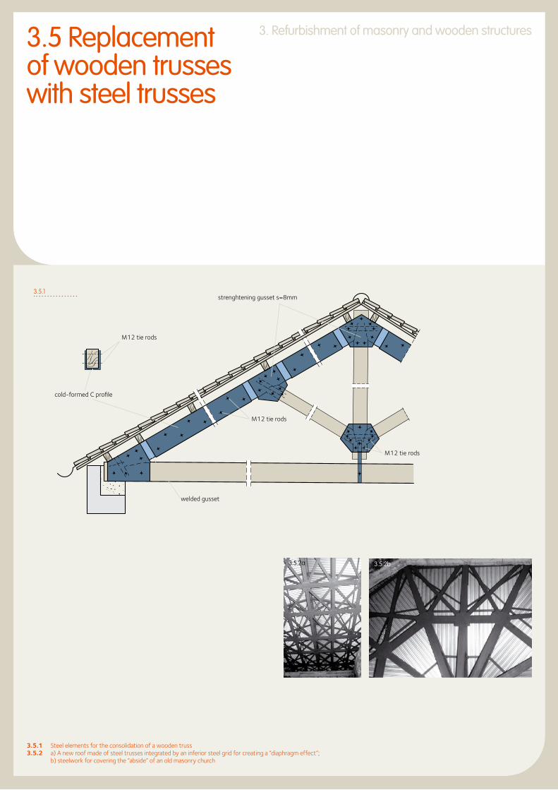
3.5.1 Steel elements for the consolidation of a wooden truss3.5.2 a) A new roof made of steel trusses integrated by an inferior steel grid for creating a “diaphragm effect”; b) steelwork for covering the “abside” of an old masonry church
strenghtening gusset s=8mm
M12 tie rods
cold-formed C profile
welded gusset
M12 tie rods
M12 tie rods
3.5.1

Wooden trusses are very often damaged by the ravages of time. In some cases they may be repaired by the addition of steel plates to the connections or along the elements (Figure 3.5.1). Often this type of repair is not carried out, the best solution being the replacement of the whole timber truss system with a new roof made of steel profiles.
Examples of this type of work on historical buildings, like palaces and churches, are present in many European countries. In particular, many churches and historical buildings have been retrofitted by replacing the old timber roof with steel trusses and finished with trapezoidal sheets.
Where the church is located in an area prone to earthquakes, the new steel trusses
may be integrated with a horizontal grid, in order to rigidly connect the top of the masonry walls and, therefore, create a “diaphragm effect” (Figures 3.5.2 a, b).
A significant example of a new steel roof is Naples Cathedral (Figure 3.5.3). The new whole roof of the Ducal Palace in Genoa is made of steel profiles (Figure 3.5.4). Many old buildings of the Royal Iron Mill of Mongiana in Calabria have been renovated by means of new steel roofs.
A roof-reversal operation has been carried out in Gevelsberg (Germany) in a building which was formerly used as a workshop and is now a garage and warehouse (Figure 3.5.5).
3.5.3 The main façade of the Naples Cathedral (Italy)3.5.4 The new steel roof of the Ducal Palace of Genoa (Italy)3.5.5 Roof renewal in Gevelsberg by means of steel beams and trapezoidal sheets
3.5.3
3.5.4
3.5.5
35
3. Refurbishment of masonry and wooden structures
35

Reichstag in Berlin, Germany

37
3. Refurbishment of masonry and wooden structures
37
3.6 Roofs made of steel and glass
3.6.1 The “Inner Court” of the Museum of Hamburg (Germany), covered by steel and glass3.6.2 The former regional parliament in Düsseldorf (Germany)
Covering the internal courtyards of historical buildings is a relatively new activity, which is very often used to extend the functional layout of the inside of the building. Two significant examples of glazing roofs are: the inner courtyard of the Museum of Hamburg (Figure 3.6.1) and the extension of the Art Gallery K21 of Düsseldorf, opened in 2002 (Figure 3.6.2).
3.6.1
3.6.2


3939
4. REFURBISHMENT OF REINFORCED CONCRETE (R.C.) STRUCTURES
4.1 Consolidation cases 404.2 Change of structural scheme: gymnasium in Cantù (Italy) 43

The increase of the load–bearing capacity in r.c. columns may be obtained by adding, in one or two directions, a couple of hot-rolled steel sections, which are connected together by means of appropriate ties. The use of channels, angles and plates makes it possible to obtain a continuous resisting perimeter, where the prestressing effect is realized by means of bolts (Figures 4.1.1 a, b).
4.1 Consolidation cases
The strengthening as well as the repair of r.c. beam-to-column joints is usually achieved through the use of angles and batten plates, which are located around the r.c. members (Figure 4.1.2).
The steelwork is welded and sometimes glued to the concrete surface. The size of the additional elements depends on the requested amount of increase in shear and bending capacity.
4.1.1b
4.1.1a
distribution plate
C profile
Non shrinkage mortar

4141
4. Refurbishment of Reinforced Concrete (R.C.) Structures
41
The increase of the inertia of r.c. beams may be obtained by connecting the r.c. section to steel plates or profiles, by means of bolts or ties and glue (Figure 4.1.3). The same system may be used to strengthen floor structures made of r.c. and clay blocks. Mixed concrete and brick floors may be strengthened using the following methods (Figure 4.1.4):
l plating the bottom of the individual concrete beams by means of steel plates, without breaking the tiles;
l reinforcing the individual concrete beams by means of steel sections;
l inserting H profiles between concrete beams in suitable openings;
l strengthening with U channels connected below each concrete beam.
4.1.1 a) Consolidation of r.c. columns by means of steel elements; b) details of “batten plates and angles” system
4.1.2 Consolidation of an r.c. beam-to-column joint by means of batten plates and angles4.1.3 Consolidation of r.c. beams by means of steel elements4.1.4 Consolidation of r.c. floor structure by means of steel elements
Block Floor
Steel channel
SlabJoist
Angle
Batten
Angle
Angle
Batten
Plate
Angle
4.1.2
4.1.3
4.1.4

4. Refurbishment of Reinforced Concrete (R.C.) Structures
The ability of the structure to resist horizontal loading may be improved by the insertion of steel braces into the r.c. meshes. A reticular shear-wall is obtained as a composite structure, where the r.c. frame is integrated by cross-bracings made of steel profiles.
Each steel bracing is inserted to the mesh of the r.c. frame and the connection between both materials must be guaranteed by means of bolts or ties alongside the perimeter frame of the steel diagonals (Figure 4.1.5).
In addition to the advantage of an easy erection, this system allows for future installation of openings for doors or windows, by using – if necessary – appropriate shapes for the diagonals or introducing only one diagonal per mesh.
HE 300 B
HE 400 B
HE 300 B
HE 300 B
HE 300 B
HE 400 B HE 240 B
HE 240 B
HE 400 B
00130032
FRONT VIEW
PLAN VIEWJacketing withsteel sheets
4.1.5

4.2.2
4343
4. Refurbishment of Reinforced Concrete (R.C.) Structures
43
An old industrial building in Cantù in the province of Como (Italy) has been converted into a gymnasium using structural steelwork to achieve a change of layout in the original reinforced concrete structure (Figure 4.2.1).
The original layout consisted of a two-storey reinforced concrete frame with intermediate columns (Figure 4.2.1 a). The conversion to a
gymnasium required completely stripping the interior of the building and eliminating the central columns and intermediate floor. The existing roof structure is now supported by new steel portals arranged in pairs on either side of the existing columns and inserted into the external walls (Figure 4.2.1 b).
4.1.5 Steel bracings for seismic upgrading of r.c. frames4.2.1 An existing industrial r.c. building in Cantù (Italy) has been converted into a gymnasium, by drastically modifying the structural scheme4.2.2 The coupled steel portals are visible on the façade
r.c. column
r.c. beam
On the front façade, the portals pierce the perimeter walls in such a way as to create an interesting architectural motif relieving the monotony of the façade (Figure 4.2.2).
Inside, the rafters of the new frame support the existing reinforced concrete roof truss directly.
4.2.1a 4.2.1b
4.2 Change ofstructural scheme:gymnasium in Cantù (Italy)


4545
5. REFURBISHMENT OF IRON/STEEL STRUCTURES
5.1 Consolidation of iron and steel structures 465.2 Change of use: rue de l’Ourcq Building, Paris (France) 51

5. Refurbishment of iron/steel structures
Resistance of iron and steel in construction has gradually increased as improvements in manufacturing and production have taken place. In the 19th century, allowable stresses for cast iron were around 20 MPa and for wrought iron around 100 MPa. Current acceptable stresses for steel, which are provided in the latest standards for design of steelwork, are very much higher. The strength of existing iron and steel structures obviously needs to be considered in relation to the standards in force at the time of original construction, although with extensive testing it may be possible to justify a slight increase in the allowable stresses specified at that time.
Various techniques may be employed to strengthen existing steel beams:
l plates or profiles may be welded to top and bottom flanges;
l channels or H-sections may be welded onto flanges;
l plates may be welded between top and bottom flanges to form a box section;
l working from above, a reinforced concrete slab may be cast and attached to the beams below using suitable connectors (angles, T-sections, bars, studs, etc) welded to the top flange to develop composite action.
In all cases, the combined use of new and existing materials must be carefully considered. If bolting is to be used the initial loss of strength of the existing member whilst the bolt holes are drilled will need consideration, as this temporary condition may prove to be critical.
If welding is used as an alternative, the specification of the welding technique must be compatible with the existing material.
Weldability or improved welding properties of the material plays a fundamental role in the refurbishment of existing iron/steel structures. In many cases the historical documentation is missing or inadequate, but it is well known
existing elements
added elements
5.1 Consolidation of iron and steel structures
that the metallic materials of the nineteenth Century were not generally suitable for welding.
The few basic rules to be considered are:
l cast iron may not be welded;
l wrought iron may be welded, provided that appropriate recommendations are followed;
l mild steels may be welded under appropriate conditions by using electrodes which are compatible (generally low hydrogen electrodes).
5.1.1

47
5. Refurbishment of iron/steel structures
5.1.1 Reinforcement of steel sections by adding welded or bolted steel elements5.1.2 Transformation of a beam-to-column joint from semi-rigid to rigid (a) or from pinned to rigid (b)5.1.3 Reinforcing of floor steel beams by adding steel elements to the bottom flange
Wood I Section
Square bar
Concrete
Clay block
Wooden deck
Angle
Beam
Cold-formed shape
Concrete Stones
Cold-formed shape
Bolt
Steel sheet
The use of steel in strengthening modern steelworks is the simplest case. In fact, it is very easy to add integrative elements to the existing structure by means of the same connecting techniques.
The section modulus of H-beams or columns may be increased in different ways by welding or bolting plates and/or shapes, which transform the original section according to the newly requested capacity (Figure 5.1.1).
It is also very easy to upgrade a beam-to-column connection and change it from simply pinned or semi-rigid to a rigid connection (Figure 5.1.2).
At the beginning of the twentieth century, timber beams used in floor structures were gradually replaced by the ancient I-sections. The steel beams were integrated firstly by a wooden deck and, later, by clay blocks, concrete or stones.
In all these cases the need to increase the section modulus may be easily fulfilled by adding appropriate steel shapes to the lower flange (Figure 5.1.3).
5.1.3
5.1.2b
5.1.2a

5. Refurbishment of iron/steel structures
When it is not possible to work from underneath, the additional steel element may be connected to the top flange (Figure 5.1.4).
Particular attention to the state of preservation is required when attaching old steel to new one. In many cases welding is not allowed due to the impure composition of the old material, and bolting is therefore advisable.
Many steel/iron constructions (buildings and bridges) of the 19th century belong to the cultural heritage of historical monuments (Figure 5.1.5). The re-use of old industrial buildings belonging to the so-called “industrial archaeology” is today an emerging activity. The Culture & Exhibition Centre “Century Hall” in Bochum was a former blast-hall of an old foundry, which was refurbished in 1993 (Figure 5.1.6).
The Exhibition Hall in Cologne has recently been restored and located inside an old steel structure covered by arches (Figures 5.1.7 a, b).
5.1.5

49
5. Refurbishment of iron/steel structures
5.1.4 Reinforcing of floor steel beams by adding steel section to the top flange5.1.5 The renovation of the old “Gare d’Orsay” in Paris, now re-used as a Museum5.1.6 The new Culture & Exhibition Centre “Century Hall” in Bochum (Germany), obtained from the transformation of a former industrial building5.1.7 The new Exhibition Hall in Cologne (Germany) after the restoration of the existing steel structure
5.1.7a 5.1.7b
5.1.6
Double T section
Slab
Concrete
Clay blockDouble T beam
Floor
SlabConcrete
Floor
ProtectionClay block
Clay block
Double T beam
5.1.4

5. Refurbishment of iron/steel structures
An old machinery building of the coal mine “Zeche Zollern” in Essen (1904) has been refurbished and transformed into a museum.
Within the industrial archaeology, the gasometers represent very symbolic structures, which are re-used for many different purposes. The gasometer of Oberhausen (Germany) has been extended and used as an exhibition hall (Figure 5.1.8).Two gasometers in Athens have been re-used as an office building and auditorium in the new Museum of Maria Callas (Figure 5.1.9).
5.1.8
5.1.9

51
5. Refurbishment of iron/steel structures
This building is situated at 135 to 145, rue de l’Ourcq and at 24 to 36, rue Labois-Rouillon in Paris. It was an industrial building originally used as a depot and baling plant for old paper and fabric, and later as a furniture warehouse. The property had to be adapted for its new role as an apartment block, whilst keeping the features of its late 19th century industrial architecture(Figure 5.2.1).
The depth of the building did not allow to use the whole of the floor area for apartments. It therefore proved necessary to form a void in the central part.
The architects made use of this constraint to create a unique interior space, strongly defined yet highly differentiated. It formed a kind of backbone which services all of the apartments, allowing them to open onto a quiet garden area away from the noise of the street and providing them with natural daylight. This layout gives the apartments individual character and a private interior street.
5.1.8 The “Gasometer” in Oberhausen (Germany) has been extended and re-used as an exhibition hall5.1.9 The “Maria Callas” Museum in Athens (Greece)5.2.1 The existing façade of an old industrial building in rue de l’Ourcq in Paris (France)
Small business premises have been built on the ground floor, along rue de l’Ourcq and on the little square. This location was chosen because of the easy access and the liveliness that it brings to the street. All of the floors, beams and columns of the steel structure inside the building built at the beginning of the 20th century were in an acceptable state with no major damage or excessive corrosion. The structure was very well suited to the change of building use since its components had been originally designed to support heavy industrial loads.
5.2 Change of use: rue de l’Ourcq Building, Paris (France)
5.2.1

5. Refurbishment of iron/steel structures
The internal columns made of cast iron are supporting the floors on a structural grid measuring 4m by 4m. Where the new arrangement created small loads, the columns were left in their original condition (Figure 5.2.2).
To carry the heavy loads the columns were encased in a square section of reinforced concrete. The columns are supported horizontally at mid-height by the beams of the mezzanine floors or by the reinforced concrete façade.
The beams were too narrow and some of them were off-centre. In most cases they were arranged in pairs, a flange width apart. Occasionally, a main girder was made up of two beams of different depths. Sometimes the beams were jointed, sometimes single. The connections were as varied as the beams. All the joints have therefore been checked and strengthened where necessary and the beam supports at the columns reinforced.
The original floors were made of joists supporting brick and clinker vaults that were covered with reinforced cement mortar. In certain areas the floor was strengthened by concrete which covered the whole depth of the joists. In other areas floors had to be demolished or reinforced.
The whole building is covered by a saw-tooth roof arranged parallel to the street.
The north-facing slopes were glazed and the southern-facing slopes were tiled. The span of the saw-tooth trusses is twice that of the floor beams at the lower level. The columns supporting the roof are generally IPN 260 sections.
The conversion to provide the inner courtyard required the removal of several north lights. The orientation of the building and its saw-tooth roof form made it ideal for the installation of solar panels for heating water.
It was necessary to provide fire resistance of half an hour for the floors and the supporting structure. The fire resistance was achieved in the apartments either by encasing in approximately 70mm thick reinforced concrete where the columns fell within the partition walls between apartments or by intumescent paint. In the business premises, rock wool casing (moulded or padded) was used with a protective plaster covering. The steel structures were kept visible in the apartments (Figure 5.2.3).
5.2.2 The original columns in the internal court5.2.3 Internal view of an apartment
5.2.2
5.2.3

Central Railway Station in Leipzig, Germany
53


5555
6. SEISMIC UPGRADING
6.1 Bracing Systems 566.2 Seismic upgrading of masonry buildings: the Capodimonte district in Ancona (Italy) 59 6.3 Passive Control Systems 616.4 Anti-Seismic Steel Roofings 626.5 Seismic upgrading by gutting: The Court of Justice in Ancona (Italy) 65

6. Seismic upgrading
The use of steel braces is very effective in strengthening both masonry and reinforced concrete structures against earthquakes. It allows for the introduction of shear walls with lattice scheme, which has the two purposes: increase the resistance of the structure to horizontal forces and balance the distribution of internal rigidity with respect to the shear centre in order to minimise dangerous torsional effects (Figure 6.1.1).
With regards to masonry structures, the steel braces may be located inside or beside the masonry wall and must be connected to the floor structures (Figure 6.1.2).
B
A
A
A - A
B - B
6.1 Bracing Systems
6.1.1

6.1.2
57
6.1.1 Different steel bracing systems for seismic upgrading of masonry and r.c. structures6.1.2 Steel braces on the facade of a masonry building (electrical power station in Hungary)6.1.3 St. Andrew cross-bracing expanded on four meshes in an r.c. frame
With regards to r.c. structures, steel profiles are connected to the perimeter of the meshes of the r.c. frame, inside which diagonals and counter-diagonals are arranged in the classical “St. Andrew’s cross” pattern or in other patterns more suited to the use of the building.
If the St. Andrew’s crosses are made at the height of two levels, the presence of a single diagonal for each rectangular panel makes it possible to provide door or window openings (Figure 6.1.3).
6. Seismic upgrading
6.1.3
Channel
Tie rod
H Profile
B-B

6.1.4
6. Seismic upgrading
Several seismic upgrading operations have been carried out all over the world through use of steel braces in the reinforced concrete frame meshes (Figure 6.1.4).
In the case of steel structures requiring upgrading to resist seismic activity because of the recent inclusion of the building in a new seismic area, strength and ductility must be improved, particularly in the joints.
Appropriate systems for strengthening the two classical types of joints (both rigid and pin-ended), by means of the introduction of stiffening elements, may be used. In the case of rigid joints, the bending capacity is then improved. In the case of pin-ended joints, the integration of stiffeners is designed to introduce a given capacity to resist bending moments, which is practically non-existent in the original joint.
The improvement in resisting horizontal actions may be easily achieved by increasing the cross-section of diagonal bracings in case of braced structures or by introducing new bracings in the case of movement-resistant structures.

There is an interesting example of seismic upgrading in the renovated district of Capodimonte in the historic centre of Ancona, the oldest part of the town, formerly inhabited by fishermen.
The masonry buildings were in an advanced state of decay caused by the extensive damage suffered during the earthquakes of 1972 and 1936 or by the bombardments suffered during the second world war. This situation had led to the precautionary evacuation of practically all the inhabitants of the district.
In all buildings with two or three storeys above ground level, the solid brick and dressed stone walls had widespread cracks and the mortar had completely lost all consistency.The need for a reliable method of restructuring these buildings led to rejection of the traditional methods of consolidation based on local strengthening of the individual constructional components. Preference was given to a solution whereby the task of transferring the loads to the foundations was completely entrusted to a new structural system.
The work carried out comprised a steel structure inserted into the perimeter and internal walls, integrated with horizontal structures of steel sections and corrugated steel sheets. The new steel skeleton, suitably connected to the bracing walls, forms an structural system independant of both vertical and horizontal loads, particularly designed to withstand the effects of seismic activity.
6.2 Seismic upgrading of masonry buildings: the Capodimonte district in Ancona (Italy)
6.1.4 The steel cross-bracings in an apartment building in Berkeley (California, USA)6.2.1 The Capodimonte district in Ancona: details of the new
steel structure inside of the masonry building
6. Seismic upgrading
6.2.1
The steel skeleton is completely autonomous and independent of the existing walls, which are downgraded to simple partition walls and do not require any load-bearing capacity (Figure 6.2.1).
59

6. Seismic upgrading
The refurbishing work was carried out in the following stages:
l creation of openings in the lower part of the walls to contain the newly reinforced concrete foundations (Figure 6.2.2);
l positioning of the anchoring bolts and base plates (Figure 6.2.3);
l after creating suitable vertical channels in the perimeter walls, erecting steel columns over the full height and temporary bracing of these at floor levels (Figure 6.2.4);
l constructing roof structures with trusses and purlins and finishing off with the existing covering of roof tiles (Figure 6.2.5);
l from the top floor, demolition of internal walls and the corresponding floor and then reconstruction of the new floor with main and secondary beams, corrugated steel sheets and cast concrete (Figure 6.2.6):
l building up the reinforced concrete walls of stairway cores with steps and landings cast on site;
l final connection of the steel framework to the existing walls and reinforced concrete staircases, then fixing with sealing concrete;
l completion with partitions, plastering, floor coverings and finishes.
The external walls, suitably restored, still retain their architectural and enclosing or protective function, but are relieved of their role as main load-bearing elements (Figure 6.2.7).
6.2.2
6.2.3 6.2.4

61
6. Seismic upgrading
The control of the structural response produced by earthquakes may be carried out by means of various systems based on different concepts, such as modifying masses or damping as well as the production of passive or active counter forces. Following the passive systems, which do not require an external power source, the properties of structure (period and/or damping capacity) do not vary depending on the seismic ground motion.
The energy-absorbing devices filter the seismic forces and thus considerably reduces the seismic impact on the protected structure. The use of passive control techniques in the refurbishing of existing buildings is a relatively new issue. The replacement of an old wooden roof with a new steel structure creates the suitable condition to conveniently apply the passive control concept to the masonry building with the aim of improving the seismic resistance of the building.
It is widely recognised that in order to ensure adequate protection against seismic activity in a masonry building it is necessary to ensure one or more floors to be able to act as rigid diaphragms. Only if this condition occurs, the efficient transmission of the horizontal forces to the vertical walls could be assured. In order to guarantee the diaphragm effect in the case of a masonry single- storey building (for instance the nave of a church), the rigid links, created between masonry and roof structures, may cause certain problems to masonry walls due to thermal variations depending on the geometrical and mechanical features of the structural scheme (span-to-height ratio).
In contrast, if the rigid link is not assured, the structure may breathe normally without transmitting stresses to the masonry. The diaphragm effect is not produced in case of earthquake.
The oleo-dynamic dampers (also called shock-block transmitter units) are able to resolve these contradictory issues, because they demonstrate the two different behaviours when required. Under thermal loads, where speed of application is very slow, the oleo-dynamic dampers act as sliding bearings: the structural system of the roof is statically determined and no additional stresses arise as a consequence of thermal variations.
During an earthquake, the devices act as fixed restraints owing to the high speed of load application: Under these conditions the structural system becomes redundant, with significant improvement in the overall seismic behaviour. The devices have a plastic threshold: when this is exceeded, significant energy dissipation occurs, which is able to reduce the effects of the seismic action on the masonry structure.
6.2.2 The new foundation and the column base6.2.3 The location of the steel column in the existing masonry wall6.2.4 Growing of the steel structure inside the masonry6.2.5 The new steel roof6.2.6 The new floor structure6.2.7 The Capodimonte district in Ancona: the old facades are kept as they were,
without showing the internal seismic resistant steel structure
6.2.5
6.2.6
6.2.7
6.3 Passive ControlSystems
6. Seismic upgrading
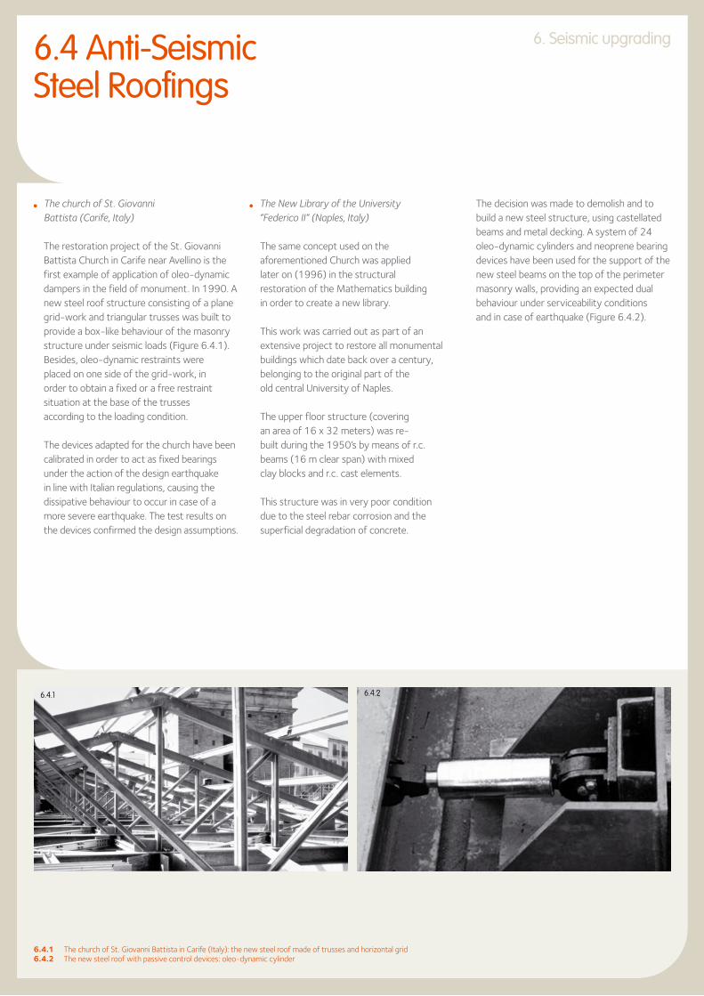
l The church of St. Giovanni Battista (Carife, Italy)
The restoration project of the St. Giovanni Battista Church in Carife near Avellino is the first example of application of oleo-dynamic dampers in the field of monument. In 1990. A new steel roof structure consisting of a plane grid-work and triangular trusses was built to provide a box-like behaviour of the masonry structure under seismic loads (Figure 6.4.1).
Besides, oleo-dynamic restraints were placed on one side of the grid-work, in order to obtain a fixed or a free restraint situation at the base of the trusses according to the loading condition.
The devices adapted for the church have been calibrated in order to act as fixed bearings under the action of the design earthquake in line with Italian regulations, causing the dissipative behaviour to occur in case of a more severe earthquake. The test results on the devices confirmed the design assumptions.
l The New Library of the University “Federico II” (Naples, Italy)
The same concept used on the aforementioned Church was applied later on (1996) in the structural restoration of the Mathematics building in order to create a new library.
This work was carried out as part of an extensive project to restore all monumental buildings which date back over a century, belonging to the original part of the old central University of Naples.
The upper floor structure (covering an area of 16 x 32 meters) was re-built during the 1950’s by means of r.c. beams (16 m clear span) with mixed clay blocks and r.c. cast elements.
This structure was in very poor condition due to the steel rebar corrosion and the superficial degradation of concrete.
6.4.1 The church of St. Giovanni Battista in Carife (Italy): the new steel roof made of trusses and horizontal grid6.4.2 The new steel roof with passive control devices: oleo-dynamic cylinder
The decision was made to demolish and to build a new steel structure, using castellated beams and metal decking. A system of 24 oleo-dynamic cylinders and neoprene bearing devices have been used for the support of the new steel beams on the top of the perimeter masonry walls, providing an expected dual behaviour under serviceability conditions and in case of earthquake (Figure 6.4.2).
6.4 Anti-Seismic Steel Roofings
6.4.1 6.4.2

6363
Court of Justice of the European Communities, Luxembourg

6. Seismic upgrading
l The industrial building of Sarno (Salerno, Italy) The seismic upgrading work was carried out
on an existing masonry single-storey industrial building. Due to the large span of the building and to the absence of intermediate walls, the use of a steel reticulated diaphragm appeared as the most appropriate choice because of its lightness and in-plane stiffness (Figure 6.4.3). Also, suitable energy dissipation devices placed at supports of roof trusses have been introduced in order to provide a significant amount of energy dissipation.
To this purpose, both oleo-dynamic and plastic threshold devices have been used (Figure 6.4.4), in order to respond adequately during daily and seasonal thermal changes to the roof, as well as low-to-moderate intensity earthquakes and severe earthquakes.
A comprehensive study of the seismic response of the structure, carried out by means of a dynamic time-history analysis, shows the effectiveness of the adopted solution.
6.4.3 The new steel roofing structure made of trusses and horizontal grids during erection (Sarno, Italy)6.4.4 Special devices for passive control in the new steel structures of Sarno (Italy): oleo-dynamic cylinder6.5.1 The historical façade of the Court of Justice in Ancona6.5.2 The internal steel structure during erection
6.4.4
6.4.3

65
6. Seismic upgrading
The building was completely gutted and restructured to house the new court offices. The arrangement of the windows, cornices and all ornaments in the masonry façades characterising its neo-renaissance style were preserved (Figure 6.5.1).
The main load-bearing structure consists of four reinforced concrete towers measuring 9x9m, containing stairs, lifts and floor services and located at the corners of the inner covered courtyard. These towers provide the vertical support to the roof and the five floors suspended from it, as well as horizontal stability to resist the effects of seismic activity.
The system of suspension in the roof consists of four pairs of truss girders supported on the inside edge of the four reinforced concrete towers, thus marking the perimeter of the covered courtyard.
Each pair of trusses forms a box girder measuring 1.80m wide, 4m high with cross-shaped wall diagonals (Figure 6.5.2).
6.5 Seismic upgrading by gutting: The Court of Justice in Ancona (Italy)
6.5.1
6.5.2

6. Seismic upgrading
All the truss members (chords, vertical and diagonal bars) are made of steel I-sections, connected by means of bolted gusset plates. The inner ring made up of four pairs of girders with a span of 21,40m represents the key component of the steel skeleton which the other members of the structure are connected to:
l inside the core the beams supporting the dome skylights, which illuminate the inner courtyard rest on the upper truss nodes;
l outside the core the cantilever beams which cover the zone outside the perimeter defined by the four towers are connected to the lower truss nodes;
l the tension rods for the five suspended floors below start off in groups of four from the truss nodes of the inner bottom chords (Figure 6.5.3).
The five floors suspended from the roof girders are attached to the four zones measuring 9x20m between the four towers (Figure 6.5.4). They consist of structural steel beams and joists supporting composite slabs.
The main interior beams are suspended by tie rods from the box girder ring, whilst on the outside they rest on the perimeter area in RC between the four towers and the exterior façades of the building.
They were connected by welding to suitable plates previously sealed in the concrete. All other structural components were assembled on site using bolted connections. The individual elements were fabricated in sizes convenient for transportation inside the historic city centre as well as erection within a highly built-up area.
6.5.3 The vertical ties from the top reticular steel girder in the court of justice in Ancona (Italy)6.5.4 The five suspended floors facing the inner courtyard of the Court of Justice
6.5.3
6.5.4

67
Atomium, Brussels, Belgium

6969
7. ADDITIONS7.1 Expansion of area: Van Leer Office Building in Amstelveen (The Netherlands) 707.2 Vertical extension super elevation: Building in Victoria Street, Toronto (Canada) 717.3 Addition in historical buildings: the old factory of Briatico and the Cultural Centre of Succivo (Italy) 727.4 Vertical extension by suspension: the Jolly Hotel in Caserta (Italy) 737.5 The Reichstag in Berlin (Germany) 747.6 Various horizontal and vertical extensions using steelwork in Germany 75

7. Additions
The office building was built at the end of the fifties to accommodate about 500 employees, but due to the decentralisation of the Van Leer organisation, only about 300 staff have worked here in recent years (Figure 7.1.1)Furthermore, as with most buildings designed before the oil crisis, the energy costs were very high.
7.1 Expansion of area: Van Leer Office Building in Amstelveen (The Netherlands)
c) Fitting the jacks- when the load is carried by the support
structure, cut the lower columns- fit lifting jacks on support- sawn-off columns on floor at 4.70m below
the existing floor and at +6.60m for re-use- support structure carries floors at
+6.60m, +12.20m and construction at +8.25m for short duration
- lifting jacks in highest position
d) Lowering the floor- remove bolts from joints between
columns of the first structure and floor beams at +6.60m
- maximum disalignement between the jack 10 mm
- check for final disalignement and for skew
e) Floor at level +4.75m- the floor is now at level +4.75m- the lower joints are welded- the removed column section
is moved up and welded.- when the column is completely welded, the
jacks and support structure can be removed
f) 2nd floor at +8.50m- fitting the hollow prestressed slabs- pour concrete screed and joints- fitting façade walls- finishing the whole building
a) Cross section of existing building - demolish all inner walls- demolish façade walls- free columns- shut off main electricity and heating system
b) Fitting the steel construction for the new floor and the temporary support structure (in yellow)
- one (light column) for the new floor to be created at +8.50m and the other one in the centre to support the existing floor.
- make use of the existing floor at 6.60m to build the new floor (in red)
- bolting of the joints- support structure from floor at +8.25
shored on all sides to carry load to foundations
- propping of this first structure which is supporting the new floor (+8.25) in order to transmit the loads to the fundations
The building consists of a central hall, with a V-shaped two-storey office wing at each end. Each office floor has a surface area of about 1 000m². The service rooms are in the central office and in separate subsidiary buildings. The storey heights are very large: 5,6m gross (4,3m net) in the office wings, while the central hall is 7,2m high.
The load-bearing structure is made of steel. There are 19 columns in each 1 000 square meters of wing. The frame is 8,0m between centres. The distance between columns varies between 8,15 to 9,0m.
When the building was originally designed, the possibility of adding an extra floor to the end wings at a later stage was taken into account in the design and construction.
7.1.1
7.1.2

71
7. Additions
The main requirements were:
l reducing the storey height in the office wings from 5,6m to 3,75m, so that within the existing building volume the usable office floor space could be increased from 4 000m² to 6 000m²,
l the design of a new, completely insulated façade, whilst retaining the original features of the building,
l the creation of new utility provisions in both wings, such as lift, stairs and toilets,
l the following solution was adopted in order to realise the first phase (Figure 7.1.2):
- fit a steel construction for the new floor at 8,25m;
- assemble the temporary support construction beneath this;
- shorten the inferior columns by 1,85m and keep these column sections;
- put the jacks in place;- release the column division and allow
the floor to be lowered by 1,85m;- replace the column sections and weld
the whole structure together.
This example shows the potential of steel for improving the vertical additions. In Toronto an existing building structure of six storeys made of reinforced concrete was designed to be super elevated by four further storeys in the same material (Figure 7.2.1).
7.2 Vertical extension super elevation: Building in Victoria Street, Toronto (Canada)
7.1.1 The Van Leer Office building in Amstelveen (The Netherlands)7.1.2 The different phases of the transformation of the steel structure from two stories to three stories7.2.1 The original r.c. building in Victoria Street (Toronto, Canada)
Contrary to the initial choice, it was later decided to use steel for the additional structure. Thanks to this, instead of four storeys, it was possible to add eight new storeys. Therefore, the super elevated building now consists of fourteen storeys instead of ten, with a significant increase in volume in contrast with the initial building plans.
7.2.1

7. Additions
The old factory of Briatico in Italy was built at the beginning of the fifteenth century. Its structure results from the evolution through the centuries of the building’s use, being subsequently used for sugar, wool and soap production.
The most recent restoration works, during the 1980’s converted the building into a sports centre, with the architectural requirements to maintain its existing features as far as possible. Steelwork was selected to create a new level of super elevation, characterised by light and seismic-resistant steel frames covered by trapezoidal sheeting (Figure 7.3.1).
The building, the former “carabinieri” barracks, was consolidated and turned into the new Cultural Centre of Succivo, Caserta (Italy).
The need to find new areas and at the same time to lighten the masonry structure also in view of its seismic upgrading was suitably fulfilled thanks to the steelwork prerequisites.
The old roof was converted into a penthouse, which is located inside the new roof structure having the shape of “Vierendeel” trusses. It produces a slight increase in the volume at the top level but a reduction in the total weight (Figure 7.3.2). The erection of the prefabricated trusses was very simple and straightforward.(Figure 7.3.3).
7.3.1 The vertical addition of an old factory in Briatico (Italy)7.3.2 The new penthouse on an historical building in Succivo (Italy)7.3.3 The new steel Vierendeel trusses during erection
7.3 Addition in historical buildings: the old factory of Briatico and the Cultural Centre of Succivo (Italy)
7.3.2
7.3.3
7.3.1
73
7. Additions
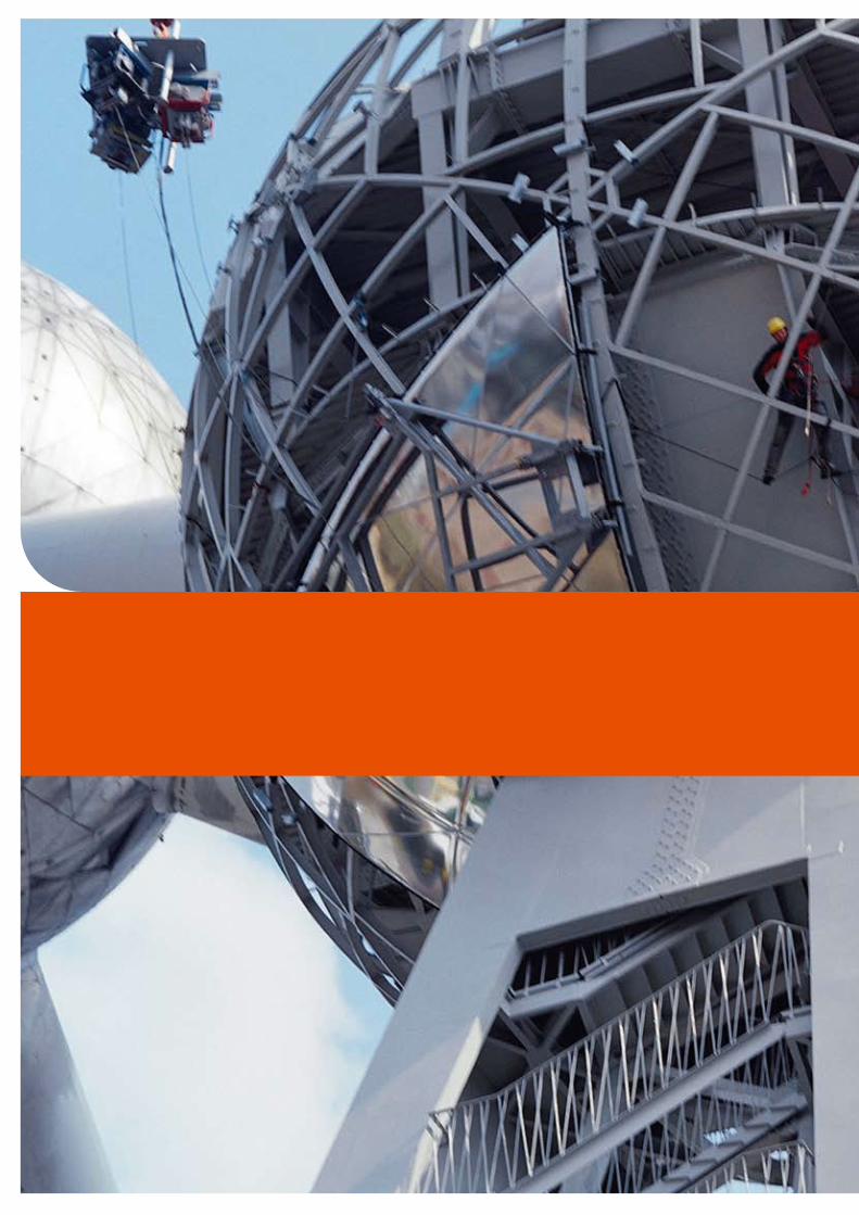
The Jolly Hotel in Caserta originally consisted of three buildings: two six-storey r.c. buildings and one three-storey masonry building in between.
A request was made to extend the intermediate masonry building by more than three storeys in order to be level with the adjacent two. As the conditions of the masonry walls, were not able to withstand this type of extension, even with some consolidation works, an alternative solution based on the use of steelwork was proposed. It consisted of the construction of five tall portal frames, from which the three new floors were suspended.
The added steel frames, outside and in the middle of the new façade, contributed to improve the aesthetic of the building.
7.4 Vertical extension by suspension: the Jolly Hotel in Caserta (Italy)

7. Additions
The restoration of the Reichstag in Berlin was the subject of an international competition won by Sir Norman Foster. The basis of the design was the replacement of the original dome with a new huge transparent hemisphere, with a central cone reflecting the natural light directly into the building and also used as natural cooling system.
The dome, measuring 38m in diameter and with a height of 23.5m, stands in the centre of the building 24m above the ground level. Its structure is composed of 24 curved ribs, rising from the bottom box girder ring, completed by 17 horizontal rings. A perimeter spiroidal ramp forms an integral part of the dome itself, acting like very stiff ring beams (Figure 7.5.1).
The modern Working Parliament is located below the dome, containing the newest communication, office and working techniques. The balconies have been built by using steelwork (Figure 7.5.2).
7.5 The Reichstag in Berlin (Germany)
7.5.2
7.5.1

75
7. Additions
An extension that includes reconstruction was built in the former administration building and pit-hoist of the Coal-Mine “Nordstern” in Gelsenkirchen, which was converted into an office and leisure centre (Figure 7.6.1).
A vertical addition was carried out in the gymnasium of Schwäbisch-Hall which enables the use of existing buildings under construction conditions (Figure 7.6.2).
The “Stadtlagerhaus” in Hamburg harbour, next to the famous fish market, exemplifies the modern combination of living and working at the waterfront of the city of Hamburg (Figure 7.6.3).
7.5.1 The new steel and glass dome of the German National Parliament, former “Reichstag”, in Berlin 7.5.2 The steelwork for the balconies of the Working Parliament of the Reichstag in Berlin (Germany)7.6.1 The Coal Mine “Nordstern” in Gelsenkirchen (Germany) after restoration7.6.2 The vertical addition of a High-School Complex in Schwäbisch-Hall (Germany)7.6.3 The “Stadtlagerhaus” in the Hamburg harbour (Germany) as a result of the restoration of an old storage and silo building
7.6 Various horizontal and vertical extensions using steelwork in Germany
7.6.2 7.6.3
7.6.1

Cognac-Jay House Old People’s Home, France

7777
7. Additions
BELGIUM
p. 67-69Atomium - BrusselsClient: ASBL Atomium VZWArchitect: Conix ArchitectenEngineering firms: Bgroup-Arbeitsgemeinschaft, GeocalPhotographers: Marc Detiffe, asbl Atomium: Marie-Françoise Plissart, Luc Tourlous
FRANCE
p. 17Dames de France - PerpignanClient: City of PerpignanArchitect: Philippe PousEngineering firm: Soulas-Etec
p. 76Cognac-Jay House Old People’s Home, Rueil-MalmaisonClient: Cognac-Jay foundationArchitects: Jean Nouvel, Didier BraultEngineering firm: BETPhotographer: Philippe Ruault
GERMANY
p. 16Christus Pavillon - Hannover Architects: Gerkan, Marg + Partner Architects
References
LUXEMBOURG
p. 23Abbey of Neumünster - LuxembourgClient: Ministry of the Public WorksArchitect: J. EwertEngineering firm: IncaPhotographer: Menn Bodson
SPAIN
p. 2-3, 5, 26-27Reina Sofia National Art Centre Museum - MadridClient: Sofia National Art Centre Museum Architects: Jean Nouvel und Alberto MedemEngineering firms: Esteyco, JG y asociados, Higini ArauPhotographers: Joaquim Cortés, José Luis Municio, Ana Müll
p. 41Bernabeu Football Stadium - MadridClient: Real Madrid C. F.Architect: Estudio LamelaPhotographers: Estudio Lamela, Francisco Pablos Laso

Technical assistance& Finishing
Finishing
As a complement to the technical capacities of our partners, we are equipped with high-performance finishing tools and offer a wide range of services, such as:
l drillingl flame cuttingl T cut-outsl notchingl camberingl curvingl straighteningl cold sawing to exact lengthl welding and fitting of studsl shot and sand blastingl surface treatment
Technical assistance
We are happy to provide you with free technical advice to optimise the use of our products and solutions in your projects and to answer your questions about the use of sections and merchant bars. This technical advice covers the design of structural elements, construction details, surface protection, fire safety, metallurgy and welding.
Our specialists are ready to support your initiatives anywhere in the world.
To facilitate the design of your projects, we also offer software and technical documentation that you can consult or download from our website:
www.arcelormittal.com/sections
Building & Construction Support
At ArcelorMittal we also have a team of multi-product professionals specialising in the construction market: the Building and Construction Support (BCS) division.
A complete range of products and solutions dedicated to construction in all its forms: structures, façades, roofing, etc. is available from the website
www.constructalia.com

79
Although every care has been taken during the production of this brochure, we regret
that we cannot accept any liability in respect of any incorrect information it may contain
or any damages which may arise through the misinterpretation of its contents.
Your partners
ArcelorMittal Commercial Sections66, rue de LuxembourgL-4221 Esch-sur-AlzetteLuxembourgTel: +352 5313 3014Fax: +352 5313 3087
www.arcelormittal.com/sections
We operate in more than 60 countries on all five continents. Please have a look at our website under “About us” to find our local agency in your country.

Notes

Federico M. Mazzolani Department of Structural Analysis and Design, University of Naples “Federico II”, Naples, Italy

ArcelorMittal Commercial Sections
66, rue de LuxembourgL-4221 Esch-sur-AlzetteLUXEMBOURGTel. + 352 5313 3014Fax + 352 5313 3087
www.arcelormittal.com/sections
Vers
ion
20
08
-1