reference manual - strumenti musicali .net · good idea to read through the entire manual once...
TRANSCRIPT

Reference Manual

This page intentionally left blank
10% 20% 30% 40% 50% 60% 70% 80% 90% 100%
Copyright 2002, Alesis. All rights reservedReproduction in whole or in part is prohibited.Specifications subject to change without notice.All trademarks are the property of their respective holders.
7-51-0114-A8/2002

Table of Contents
1
Introduction....................................................................3Welcome! .........................................................................................................3
About the Phlngr............................................................................4Important features of your Phlngr..............................................................4Phlngr Key Features ......................................................................................5
How to Use This Manual.............................................................6
Safety Instructions/Notices .....................................7Important Safety Instructions (English)............................7
Safety symbols used in this product............................................................7Please follow these precautions when using this product: .....................7
CE Declaration Of Conformity................................................9FCC Compliance Statement......................................................9
Instructions de Sécurité Importantes (French) .........................................10Lesen Sie bitte die folgende Sicherheitshinweise
(German) ..................................................................................................12
Quick Start Guide ........................................................15If you can’t wait to get started......................................................................15Hook it up to a synthesizer...........................................................................15
A quick overview of the controls ...........................................16Rear Panel ........................................................................................................16
Connections ....................................................................17Unpacking and Inspection............................................................................17Installing in a Rack .........................................................................................17Power................................................................................................................17Connecting to the Channel Inserts of a mixing console: ........................19Connecting to the Main Outputs of a mixing console: ...........................20Connecting to the Effect Send/Return of a mixing
console: .....................................................................................................21Connecting to the inserts on an instrument amplifier: ............................22Connecting to equipment with XLR inputs and outputs:.......................23About audio cables.........................................................................................23
Using the ModLink........................................................................24
Using the Phlngr...........................................................25About flanging.................................................................................25
Stereo source ...................................................................................................26Mono source ...................................................................................................26What is Tempo Sync? ....................................................................................27To turn Tempo Sync off: ..............................................................................27
Description of Controls...............................................................28Rate ...................................................................................................................28Depth................................................................................................................28Center ...............................................................................................................29Regen................................................................................................................29TYPE Rocker Switch.....................................................................................32
Table Of Contents
2
Reset Mod........................................................................................................34Tap Tempo......................................................................................................35Bypass...............................................................................................................36Using the Foot Switch ...................................................................................36
Sample Settings.............................................................37Blank Settings Templates ..............................................................................40
Troubleshooting............................................................41Troubleshooting Index................................................................41
Avoiding ground loop noise.........................................................................43Line conditioners and spike protectors ......................................................44
Care and Maintenance ................................................................45Cleaning............................................................................................................45Refer all servicing to Alesis...........................................................................45Obtaining repair service ................................................................................46
Specifications.................................................................47Audio Input .....................................................................................................47Audio Output..................................................................................................47Audio Performance........................................................................................47Mechanical .......................................................................................................47
Index...................................................................................49
Warranty/Contact Alesis ...........................................50Alesis Limited Warranty................................................................................50Alesis Contact Information ..........................................................................51
Introduction
3
Welcome!
Thank you for making the Alesis Phlngr a part of your studio.Since 1984, we've been designing and building creative tools forthe audio community. We believe in our products, because we'veheard the results that creative people like you have achieved withthem. One of Alesis' goals is to make high-quality studioequipment available to everyone, and this Reference Manual is animportant part of that. After all, there's no point in makingequipment with all kinds of capabilities if no one explains how touse them. So, we try to write our manuals as carefully as we buildour products.
The goal of this manual is to get you the information you need asquickly as possible, with a minimum of hassle. We hope we'veachieved that. If not, please drop us an email and give us yoursuggestions on how we could improve future editions of thismanual.
We hope your investment will bring you many years of creativeenjoyment and help you achieve your goals.
Sincerely,The people of Alesis
For more effectiveservice and productupdate notices, pleaseregister your Phlngronline at:http://www.alesis.com/support/warranty.htm
Introduction
4
About the Phlngr
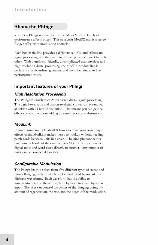
Your new Phlngr is a member of the Alesis ModFX family ofperformance effects boxes. This particular ModFX unit is a stereoflanger effect with modulation controls.
Each box in the line provides a different set of sound effects andsignal processing, and they are easy to arrange and connect to eachother. With a uniform, friendly, uncomplicated user interface andhigh-resolution digital processing, the ModFX product line isperfect for keyboardists, guitarists, and any other studio or liveperformance artists.
Important features of your Phlngr
High Resolution Processing
The Phlngr internally uses 28-bit stereo digital signal processing.The digital-to-analog and analog-to-digital conversion is sampledat 48kHz with 24 bits of resolution. That means you can get theeffect you want, without adding unwanted noise and distortion.
ModLink
If you’re using multiple ModFX boxes to make your own uniqueeffects chain, ModLink makes it easy to hookup without needingpatch cords between units in a chain. The nine-pin connectorsbuilt into each side of the case enable a ModFX box to transferdigital audio and word clock directly to another. Any number ofunits can be connected together.
Configurable Modulation
The Phlngr lets you select from five different types of stereo andmono flanging, each of which can be modulated by one of fivedifferent waveforms. Each waveform has the ability tosynchronize itself to the tempo, both by tap tempo and by audioinput. The user can control the center of the flanging point, theamount of regeneration, the rate, and the depth of the modulation.
Introduction
5
Phlngr Key Features
• High-quality stereo flanging effect with configurablemodulation settings
• Tempo synchronization for flange speed keeps effectsmodulation in time with the music
• Tap Tempo makes it easy to set the Phlngr’s speed by tappinga beat on the top panel
• Uniform, friendly, uncomplicated user interface—no fiddlingwith complicated menus or “hidden” knobs
• Reset Mod lets you reset the phase of any modulation shapefrom its beginning
• Stereo processing via four 1/4” unbalanced connectors• ModLink port, a cable-free connection that transfers digital
audio and word clock to other boxes in the ModFX family
• Footswitch connection to control the bypass function• Ability to mount 3 ModFX boxes in the optional ModFX
rack adapter
• Input trim control to adjust input level• Internal 28-bit digital processing• 24-bit D/A and A/D conversion at 48kHz sampling rate for
quiet, distortion-free effects
• External 9VAC power supply included
Introduction
6
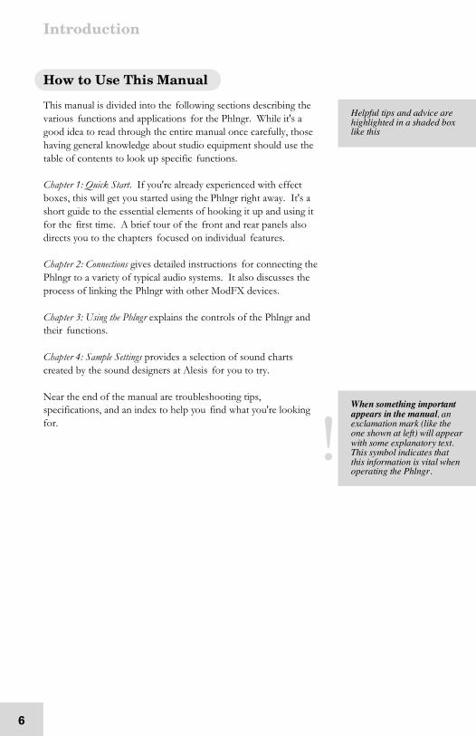
How to Use This Manual
This manual is divided into the following sections describing thevarious functions and applications for the Phlngr. While it's agood idea to read through the entire manual once carefully, thosehaving general knowledge about studio equipment should use thetable of contents to look up specific functions.
Chapter 1: Quick Start. If you're already experienced with effectboxes, this will get you started using the Phlngr right away. It's ashort guide to the essential elements of hooking it up and using itfor the first time. A brief tour of the front and rear panels alsodirects you to the chapters focused on individual features.
Chapter 2: Connections gives detailed instructions for connecting thePhlngr to a variety of typical audio systems. It also discusses theprocess of linking the Phlngr with other ModFX devices.
Chapter 3: Using the Phlngr explains the controls of the Phlngr andtheir functions.
Chapter 4: Sample Settings provides a selection of sound chartscreated by the sound designers at Alesis for you to try.
Near the end of the manual are troubleshooting tips,specifications, and an index to help you find what you're lookingfor.
H elpful tips an d ad v ic e a re h ig hlig h te d in a sh a de d b ox lik e th is
Whe n so m ething im po r ta nta pp ea rs in the ma nua l, a ne xc la ma tio n m ar k (like th eo ne s ho wn at le ft) will a pp ea rwith so m e ex p la na to r y te x t.This sy m bo l ind ic ate s th a tthis in for ma tio n is vita l whe no pe ra tin g th e Phlng r .

Safety Instructions/Notices
7
Important Safety Instructions (English)
Safety symbols used in this product
This symbol alerts the user that there are importantoperating and maintenance instructions in the literatureaccompanying this unit.
This symbol warns the user of uninsulated voltage withinthe unit that can cause dangerous electric shocks.
This symbol warns the user that output connectors containvoltages that can cause dangerous electrical shock.
Please follow these precautions when usingthis product:
1. Read these instructions.2. Keep these instructions.3. Heed all warnings.
4. Follow all instructions.5. Do not use this apparatus near water.6. Clean only with a damp cloth. Do not spray any liquid cleaner
onto the faceplate, as this may damage the front panelcontrols or cause a dangerous condition.
7. Install in accordance with the manufacturer's instructions.8. Do not install near any heat sources such as radiators, heat
registers, stoves, or other apparatus (including amplifiers) thatproduce heat.
9. Do not defeat the safety purpose of the polarized orgrounding-type plug. A polarized plug has two blades withone wider than the other. A grounding-type plug has twoblades and a third grounding prong. The wide blade or thethird prong are provided for your safety. When the providedplug does not fit into your outlet, consult an electrician forreplacement of the obsolete outlet.
10. Protect the power cord from being walked on or pinched,particularly at plugs, convenience receptacles, and the pointwhere they exit from the apparatus.
Continued next page

Important Safety Instructions
8
11. Use only attachments or accessories specified by themanufacturer.
12. Use only with a cart, stand, bracket, or table designed for usewith professional audio or music equipment. In anyinstallation, make sure that injury or damage will not resultfrom cables pulling on the apparatus and its mounting. If acart is used, use caution when moving the cart/apparatuscombination to avoid injury from tip-over.
13. Unplug this apparatus during lightning storms or when unusedfor long periods of time.
14. Refer all servicing to qualified service personnel. Servicing isrequired when the apparatus has been damaged in any way,such as when the power-supply cord or plug is damaged, liquidhas been spilled or objects have fallen into the apparatus, theapparatus has been exposed to rain or moisture, does notoperate normally, or has been dropped.
15. This unit produces heat when operated normally. Operate in awell-ventilated area with at least six inches of clearance fromperipheral equipment.
16. This product, in combination with an amplifier andheadphones or speakers, may be capable of producing soundlevels that could cause permanent hearing loss. Do notoperate for a long period of time at a high volume level or at alevel that is uncomfortable. If you experience any hearing lossor ringing in the ears, you should consult an audiologist.
17. Do not expose the apparatus to dripping or splashing. Do notplace objects filled with liquids (flower vases, soft drink cans,coffee cups) on the apparatus.
18. WARNING: To reduce the risk of fire or electric shock, donot expose this apparatus to rain or moisture.
Important Safety Instructions
9
CE Declaration Of Conformity
See our website at:
http://www.alesis.com
FCC Compliance Statement
This device complies with Part 15 of the FCC rules. Operation issubject to the following two conditions: (1) This device may notcause harmful interference and (2) this device must accept anyinterference received, including interference that may causeundesired operation.
NOTE: This equipment has been tested and found to complywith the limits for a Class B digital device, pursuant to Part 15 ofthe FCC Rules. These limits are designed to provide reasonableprotection against harmful interference in a residential installation.This equipment generates, uses and can radiate radio frequencyenergy and, if not installed and used in accordance with theinstructions, may cause harmful interference to radiocommunications. However, there is no guarantee that interferencewill not occur in a particular installation. If this equipment doescause harmful interference to radio or television reception, whichcan be determined by turning the equipment off and on, the user isencouraged to try to correct the interference by one or more ofthe following measures:
• Reorient or relocate the receiving antenna.
• Increase the separation between the equipment and receiver.
• Connect the equipment into an outlet on a circuit differentfrom that to which the receiver is connected.
• Consult the dealer or an experienced radio/TV technician forhelp.

Important Safety Instructions
10
Instructions de Sécurité Importantes (French)
Symboles utilisés dans ce produit
Ce symbole alèrte l’utilisateur qu’il existe des instructionsde fonctionnement et de maintenance dans la documentationjointe avec ce produit.
Ce symbole avertit l’utilisateur de la présence d’unetension non isolée à l’intérieur de l’appareil pouvant engendrer deschocs électriques.
Ce symbole prévient l'utilisateur de la présence de tensionssur les raccordements de sorties, représentant un risqued'électrocution.
Veuillez suivre ces précautions lors del’utilisation de l’appareil:
1. Lisez ces instructions.2. Gardez ces instructions.3. Tenez compte de tous les avertissements.4. Suivez toutes les instructions.5. N’utilisez pas cet allareil à proximité de l’eau.
6. Ne nettoyez qu’avec un chiffon humide. Il est potentiellementdangereux d'utiliser des pulvérisateurs ou nettoyants liquidessur cet appareil.
7. Installez selon les recommandations du constructeur.8. Ne pas installer à proximilé de sources de chaleur comme
radiateurs, cuisinière ou autre appareils (don’t lesamplificateurs) produisant de la chaleur.
9. Ne pas enlever la prise de terre du cordon secteur. Une prisemurale avec terre deux broches et une troisièrme reliée à laterre. Cette dernière est présente pour votre sécurité. Si lecordon secteur ne rentre pas dans la prise de courant,demandez à un électricien qualifié de remplacer la prise.
10. Evitez de marcher sur le cordon secteur ou de le pincer, enparticulier au niveau de la prise, et aux endroits où il sor del’appareil.
Suite de la page suivante

Important Safety Instructions
11
11. N’utilisez que des accessoires spécifiés par le constructeur.12. N’utilisez qu’avec un stand, ou table conçus pour l’utilisation
d’audio professionnel ou instruments de musique. Dans touteinstallation, veillez de ne rien endommager à cause de câblesqui tirent sur des appareils et leur support.
13. Débranchez l’appareil lors d’un orage ou lorsqu’il n’est pasutilisé pendant longtemps.
14. Faites réparer par un personnel qualifié. Une réparation estnécessaire lorsque l’appareil a été endommagé de quelque sorteque ce soit, par exemple losrque le cordon secteur ou la prisesont endommagés, si du liquide a coulé ou des objets se sontintroduits dans l’appareil, si celui-ci a été exposé à la pluie ou àl’humidité, ne fonctionne pas normalement ou est tombé.
15. Puisque son fonctionement normale génère de la chaleur,placez cet appareil au moins 15cm. des équipmentspéripheriques et assurez que l’emplacement permet lacirculation de l’air.
16. Ce produit, utilisé avec un amplificateur et un casque ou desenceintes, est capable de produite des niveaux sonorespouvant engendrer une perte permanente de l’ouïe. Nel’utilisez pas pendant longtemps à un niveau sonore élevé ou àun niveau non confortable. Si vous remarquez une perte del’ouïe ou un bourdonnement dans les oreilles, consultez unspécialiste.
17. N'exposez pas l'appareil à l'égoutture ou à l'éclaboussement.Ne placez pas les objets remplis de liquides (vases à fleur,boîtes de boisson non alcoolique, tasses de café) sur l'appareil.
18. AVERTISSEMENT: Pour réduire le risque du feu ou dedécharge électrique, n'exposez pas cet appareil à la pluie ou àl'humidité.

Important Safety Instructions
12
Lesen Sie bitte die folgende Sicherheitshinweise (German)
Sicherheit Symbole verwendet in diesemProdukt
Dieses Symbol alarmiert den Benutzer, daß es wichtigeFunktionieren und Wartung Anweisungen in der Literatur gibt, diediese Maßeinheit begleitet.
Dieses Symbol warnt den Benutzer der nicht isoliertenSpannung innerhalb der Maßeinheit, die gefährliche elektrischeSchläge verursachen kann.
Dieses Symbol warnt den Benutzer, dem AusgabesteckerSpannungen enthalten, die gefährlichen elektrischen Schlagverursachen können.
Folgen Sie bitte diesen Vorkehrungen, wenndieses Produkt verwendet wird:
1. Lesen Sie die Hinweise.2. Halten Sie sich an die Anleitung.3. Beachten Sie alle Warnungen.4. Beachten Sie alle Hinweise.
5. Bringen Sie das Gerät nie mit Wasser in Berührung.6. Verwenden Sie zur Reinigung nur ein weiches Tuch.
Verwenden Sie keine flüssigen Reinigungsmittel. Dies kanngefährliche Folgen haben.
7. Halten Sie sich beim Aufbau des Gerätes an die Angaben desHerstellers.
8. Stellen Sie das Gerät nich in der Nähe von Heizkörpern,Heizungsklappen oder anderen Wärmequellen (einschließlichVerstärkern) auf.
9. Verfehlen Sie nicht den Zweck des grounging Terminals aufdem Netzstecker. Dieses Terminal wird für Ihre Sicherheit zurVerfügung gestellt.
10. Verlegen Sie das Netzkabel des Gerätes niemals so, daß mandarüber stolpern kann oder daß es gequetscht wird.
Fortsetzung auf nächster Seite

Important Safety Instructions
13
11. Benutzen Sie nur das vom Hersteller empfohlene Zubehör.12. Verwenden Sie ausschließlich Wagen, Ständer, oder Tische, die
speziell für professionelle Audio- und Musikinstrumentegeeignet sind. Achten Sie immer darauf, daß die jeweiligenGeräte sicher installiert sind, um Schäden und Verletzungen zuvermeiden. Wenn Sie einen Rollwagen benutzen, achten Siedarauf, das dieser nicht umkippt, um Verletzungenauszuschließen.
13. Ziehen Sie während eines Gewitters oder wenn Sie das Gerätüber einen längeren Zeitraum nicht benutzen den Netzstecheraus der Steckdose.
14. Die Wartung sollte nur durch qualifiziertes Fachpersonalerfolgen. Die Wartung wird notwendig, wenn das Gerätbeschädigt wurde oder aber das Stromkabel oder der Stecker,Gegenstände oder Flüssigkeit in das Gerät gelangt sind, dasGerät dem Regen oder Feuchtigkeit ausgesetzt war unddeshalb nicht mehr normal arbeitet oder heruntergefallen ist.
15. Dieses Gerät produziert auch im normalen Betrieb Wärme.Achten Sie deshalb auf ausreichende Lüftung mit mindestens15 cm Abstand von anderen Geräten.
16. Dieses Produkt kann in Verbindung mit einem Verstärker undKopfhörern oder Lautsprechern Lautstärkepegel erzeugen, dieanhaltende Gehörschäden verursachen. Betreiben Sie es nichtüber längere Zeit mit hoher Lautstärke oder einem Pegel, derIhnen unangenehm is. Wenn Sie ein Nachlassen des Gehörsoder ein Klingeln in den Ohren feststellen, sollten Sie einenOhrenarzt aufsuchen.
17. Setzen Sie den Apparat nicht Bratenfett oder dem Spritzenaus. Plazieren Sie die Nachrichten, die mit Flüssigkeiten(gefüllt werden Blumevases, Getränkdosen, Kaffeetassen)nicht auf den Apparat.
18. WARNING: um die Gefahr des Feuers oder des elektrischenSchlages zu verringern, setzen Sie diesen Apparat nicht Regenoder Feuchtigkeit aus.

Important Safety Instructions
14
This page intentionally left blank.

1 Quick Start Guide
15
If you can’t wait to get started
The Alesis Phlngr is a unique product, but its basic hookup andoperation is similar to other effects units in most respects. Ifyou're experienced with signal processors, this chapter is a"shorthand" guide for those who want to start using the Phlngrright away. If you have questions about any of the features, don’tworry – later chapters will unveil the mysteries of the Phlngr'sspecial features.
Hook it up to a synthesizer
1. First, make sure the power is off to all the componentsyou’re connecting to: amp, mixer, and instruments.
2. Pull the Phlngr and its power supply out of the package.3. Using a pair of 1/4” instrument cables, plug the outputs
of the synthesizer into the INPUTS on the back of thePhlngr.
4. Connect the OUTPUTS of the Phlngr to the inputs of amixer, powered speakers, or instrument amplifier.
5. Insert the power jack of the Phlngr’s power adapter intothe POWER 9VAC input on the rear panel of thePhlngr and plug the power adapter into an AC outlet(preferably on a power strip with its switch off).
The Phlngr doesn’t have a POWER switch of its own. Themoment you plug in the power, its top panel LEDs will come on.
6. Turn the power on to the system: the keyboard, thenthe Phlngr’s power strip (if it’s not already on), then themixer, then the amp.
7. Turn the INPUT TRIM knob on the back of the Phlngrwhile playing the keyboard to adjust the input level. TheSIGNAL LED on the top panel will light green, not red,when the level is correct.
8. Experiment with the knob and button settings on thePhlngr to create different sounds.
For more detailed information on connecting the Phlngr, seechapter 2: Connections.
If you're new to signalprocessing...s ta rt with th e mo re de ta ile dins tr uc tio ns fo r ho o ku p a nd o pe ra tio n sta rtin g in th e n ex tc ha pter .
1 Quick Start Guide
16
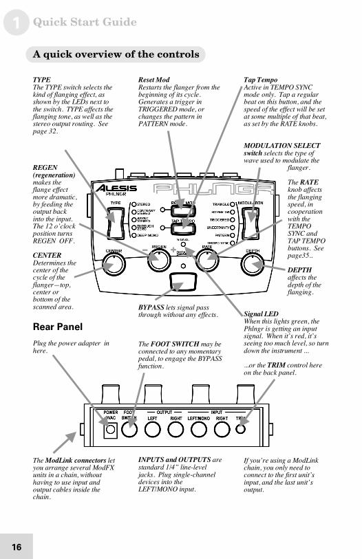
A quick overview of the controls
TYPEThe TYPE s witch s ele cts the k in d of flan g in g effec t, as s ho wn b y the LED s ne x t to the s witch . TYPE a ffe cts the fla ng in g ton e , as we ll a s the s te re o o utpu t r ou tin g. S ee p ag e 3 2.
REG EN ( re ge ne r atio n)m ak es th efla ng e e ffec tm or e dr a ma tic ,b y fe ed ing th eo utpu t b ac kinto th e inp u t.The 1 2 o ’c lo c kp os itio n tur n sREG EN O FF.
CEN TERD eter min es th ec en te r o f th e c yc le o f the fla ng er —to p,c en te r o rb otto m o f th e s ca nn ed ar ea .
Rear Panel
Plu g th e p owe r ad ap ter in h er e.
The Mod Link co nnec tor s le ty ou a rr a ng e s ev er al Mo dFXu nits in a c h ain, with ou th av in g to us e inp ut an do utpu t c ab le s ins id e the c ha in .
Res et Mo dRes ta rts the fla ng er fr om th eb eg in nin g of its cy c le .G en er ate s a trigg er in TRI GG ERED mo d e, o rc ha ng es th e p atte rn in PATTERN mo de .
BYPASS le ts s ign al pa ss thr ou gh with o ut a ny effe c ts .
The FOO T SWI TCH ma y be c on ne cte d to an y mo m en ta r yp ed al, to en g ag e th e BYPASS fun ctio n .
I NPUTS a nd O U TPUTS a re s ta nd ar d 1 /4 ” lin e- lev eljac ks . Plug sing le - ch an n eld ev ic es in to th eLEFT/MO NO in p ut.
Tap Tem p oActiv e in TEMPO S YNCm od e o nly. Tap a re gu la r b ea t on th is bu tton , a nd th es pe ed o f the effe ct will be s eta t so me mu ltiple of th at be at,a s se t b y th e RATE k no bs .
MOD ULATI ON SELECTs witc h s elec ts th e typ e ofwav e us e d to mo du la te th e
fla ng er .
The RATEk no b affec ts the fla n ging s pe ed , inc oo pe ra tio nwith th e TEMPO S YNC an d TAP TEMPOb utto ns . Se e p ag e3 5..
D EPTH a ffec ts th ed ep th o f the fla ng in g .
Sig na l LED Whe n th is lig hts gr e en , the Phlng r is ge tting a n inp u ts ig na l. Whe n it’ s r ed , it’ ss ee in g too m u ch lev e l, s o tur nd own th e ins tr um e nt ...
...o r th e TRI M co ntro l h er e o n th e b ac k p an el.
I f yo u’ r e us ing a Mo dLin k c ha in , y ou o n ly n ee d toc on ne ct to th e firs t u nit’s inp ut, a nd th e la st un it’ so utpu t.
2 Connections
17
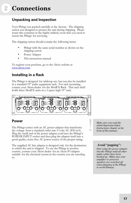
Unpacking and Inspection
Your Phlngr was packed carefully at the factory. The shippingcarton was designed to protect the unit during shipping. Pleaseretain this container in the highly unlikely event that you need toreturn the Phlngr for servicing.
The shipping carton should contain the following items:
• Phlngr with the same serial number as shown on theshipping carton
• Power Adapter• This instruction manual
To register your purchase, go to the Alesis website atwww.alesis.com.
Installing in a Rack
The Phlngr is designed for tabletop use, but can also be installedin a standard 19" audio equipment rack. For rack mounting,contact your Alesis dealer for the ModFX Rack. This rack shelfholds three ModFX units in a 3-space high 19” rack.
Power
The Phlngr comes with an AC power adapter that transformsthe voltage from a standard outlet into 9 volts AC (830 mA).Plug the small end of the power adapter cord into the Phlngr’sPOWER INPUT socket and then plug the adapter itself into agood quality, noise-free AC power source of the proper rating.
The supplied AC line adapter is designed only for the destinationto which the unit is shipped. To use the Phlngr in anothercountry, contact your Alesis dealer for an Alesis P3 adaptersuitable for the electrical system in the country you are travelingto.
Mak e su r e yo u r ea d the initial Im po r ta nt S a fe ty I ns tr uc tio ns ch ap te r a t the fro nt o f this m an ua l.
Avoid “popping”:D on ’t p lug th e po we r a da p te rinto th e Phln gr u ntil all o th er a ud io c a bles ha ve b e en h oo ke d u p. Mak e su r e yo u ra mp lifie r or po we re d s pe ak er s a re switch e d offwhe n plu gg in g in th e Phln gr to av oid d am a ge .
2 Connections
18
Connecting audio
The Phlngr will work in many different applications, whether youare connecting an instrument directly into it, or connecting itthrough a mixing console. But since the Phlngr is a stereoeffect unit, it’s important to know whether the source and/orthe system will be stereo or mono. The Phlngr is great fortaking a mono source and making it into a complex, layeredstereo signal, or it can take a stereo signal and flange each sideseparately.
Note that whenever a connection is made to the [RIGHT INPUT]of the Phlngr, it will keep the outputs discrete (left to left, right toright), unless the TYPE is set to DEEP MONO.
Mono In, Mono or Stereo Out
If you’re connecting a guitar or bass directly to the Phlngr, hook itup this way:
1. Connect a 1/4" phone cord to the [LEFT/MONO] INPUTof the Phlngr from any mono source. (The Left input willthen feed both outputs of the effect.)
2. Connect another 1/4" phone cord from the LEFT OUTPUTof the Phlngr to the amp or mixer input.
3. If the amp or mixer is stereo, connect a second 1/4" phonecord from the RIGHT OUTPUT of the Phlngr to the otherinput of the stereo amplification system, or the next mixerinput.
4. If you’re connecting directly to a stereo mixer, pan the twochannels hard left and hard right to get the maximum effect.
Whe n co n ne cting a ud ioc ab le s a nd /o r tur nin g po wer o n an d o ff, m ak e su r e th a t alld ev ic es in y o ur s ys tem a r etur ne d o ff a n d th e v olum e c on tr ols a re tu rn ed do wn .
Turn up the trim...Mos t gu ita rs an d ba s se s h av er elativ e ly lo w ou tp u t le v els.For the qu ie tes t effec t, tu rn u p th e v olum e o n th e g uitar tofull, th en c r an k up th e[ TRIM] c on tr o l on th e ba c ko f th e Phlng r u ntil th eS IG NAL LED o n its to p pa n elfla sh es re d while y o u pla y,the n ba c k it off a b it.
Connections 2
19
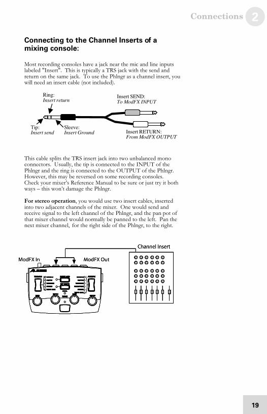
Connecting to the Channel Inserts of amixing console:
Most recording consoles have a jack near the mic and line inputslabeled "Insert". This is typically a TRS jack with the send andreturn on the same jack. To use the Phlngr as a channel insert, youwill need an insert cable (not included).
This cable splits the TRS insert jack into two unbalanced monoconnectors. Usually, the tip is connected to the INPUT of thePhlngr and the ring is connected to the OUTPUT of the Phlngr.However, this may be reversed on some recording consoles.Check your mixer’s Reference Manual to be sure or just try it bothways – this won’t damage the Phlngr.
For stereo operation, you would use two insert cables, insertedinto two adjacent channels of the mixer. One would send andreceive signal to the left channel of the Phlngr, and the pan pot ofthat mixer channel would normally be panned to the left. Pan thenext mixer channel, for the right side of the Phlngr, to the right.
I ns er t SEN D:To Mo dFX I NPU T
I ns er t RETURN :Fro m Mo d FX O U TPUT
Rin g:I ns er t r etur n
Tip : Sle ev e:I ns er t s en d I ns er t G ro un d

2 Connections
20
Connecting to the Main Outputs of a mixingconsole:
In addition to channel inserts, most mixing consoles have maininsert jacks near the main outputs. You can use insert cables toconnect the Phlngr to the main L/R bus the same way youconnect it to a pair of channels. Simply connect one insert cableto the left main insert of the mixer, and connect the two monojacks to the left INPUT and OUTPUT of the Phlngr. Use anotherinsert cable to connect the right main insert to the right INPUTand OUTPUT of the Phlngr.
Alternatively, you could plug the mixing console’s main outputsdirectly into the Phlngr’s inputs, then feed the Phlngr’s outputs toyour monitor amps or mixdown recorder. However, if you fadedown the volume at the end of the song, the sound quality maychange as you fade. This is why it’s better to use the insert jacks, ifavailable.
Connections 2
21
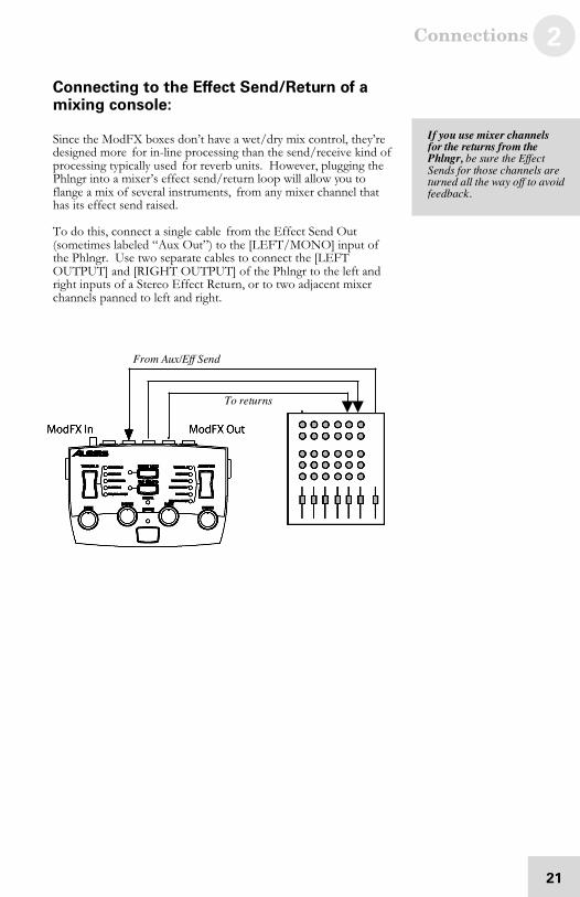
Connecting to the Effect Send/Return of amixing console:
Since the ModFX boxes don’t have a wet/dry mix control, they’redesigned more for in-line processing than the send/receive kind ofprocessing typically used for reverb units. However, plugging thePhlngr into a mixer’s effect send/return loop will allow you toflange a mix of several instruments, from any mixer channel thathas its effect send raised.
To do this, connect a single cable from the Effect Send Out(sometimes labeled “Aux Out”) to the [LEFT/MONO] input ofthe Phlngr. Use two separate cables to connect the [LEFTOUTPUT] and [RIGHT OUTPUT] of the Phlngr to the left andright inputs of a Stereo Effect Return, or to two adjacent mixerchannels panned to left and right.
I f yo u use m ixe r cha nnels f or the re tur ns f ro m the Phlng r, b e su re th e Effec tS en ds fo r th o se c ha n ne ls ar etur ne d a ll th e wa y o ff to a vo id fee db ac k .
Fro m Aux /Eff S en d
To re tu r ns
2 Connections
22
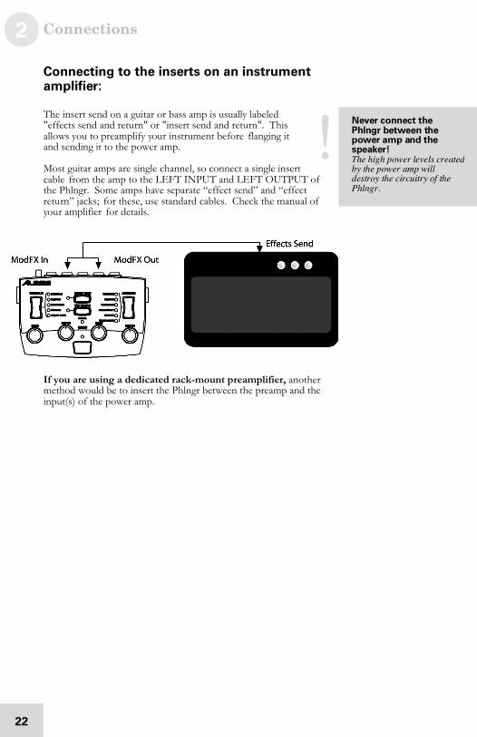
Connecting to the inserts on an instrumentamplifier:
The insert send on a guitar or bass amp is usually labeled"effects send and return" or "insert send and return". Thisallows you to preamplify your instrument before flanging itand sending it to the power amp.
Most guitar amps are single channel, so connect a single insertcable from the amp to the LEFT INPUT and LEFT OUTPUT ofthe Phlngr. Some amps have separate “effect send” and “effectreturn” jacks; for these, use standard cables. Check the manual ofyour amplifier for details.
If you are using a dedicated rack-mount preamplifier, anothermethod would be to insert the Phlngr between the preamp and theinput(s) of the power amp.
N e v e r c o nn e c t t he P hl ng r be t w e e n th e p ow e r a m p an d t he s pe a k e r ! The h ig h p owe r le ve ls cr e ated b y th e p ower am p willd es tr oy th e c ir cu itr y of th ePhlng r.
Connections 2
23
Connecting to equipment with XLR inputsand outputs:
If you are connecting the Phlngr to a product with XLR balancedinputs and outputs, you will need to convert this signal to a 1/4”unbalanced connector. Make sure that Pin 2 of the XLRconnector is connected to the Tip of the 1/4” adapter or cable.
Watch out for high levels, however: some XLR sources put outlevels close to the maximum the Phlngr can accept (about +12dBu) even when its trim is at minimum. Lower the level of thesource if the [SIGNAL] LED flashes red.
About audio cables
The connections between the Phlngr and your studio are yourmusic’s lifeline, so use only high quality cables. These should below-capacitance shielded cables with a stranded (not solid) internalconductor and a low-resistance shield. Although quality cablescost more, they do make a difference.
Route cables to the Phlngr correctly by observing the followingprecautions:
• Do not bundle audio cables with AC power cords.
• Avoid running audio cables near sources ofelectromagnetic interference such as transformers,monitors, computers, etc.
• Do not place cables where they can be stepped on.Stepping on a cable may not cause immediate damage,but it can compress the insulation between the centerconductor and shield (degrading performance) or reducethe cable’s reliability.
• Avoid twisting the cable or having it make sharp, rightangle turns.
• Never unplug a cable by pulling on the wire itself.Always unplug by firmly grasping the body of the plugand pulling directly outward.
Don't use linetransformers:Man y XLR-to- 1 /4 " ad a pter s s old at elec tro nics stor e s ar eNOT a da p te rs , b uttra ns fo r me rs (a nd v e ry lo wq ua lity tr an s fo rm er s a t tha t) .D on 't u s e th e se o n the o u tp uto f th e Phlng r —the y'r eu nn ec es s ar y a nd g en e ra lly s ou nd a wfu l b ec au se th ey d on 't h a ve th e he ad r oo m toh an dle the Phlng r's o utp ut.G et a h a rd -wire d ad a pter or c ab le fr om y o ur p ro fes sio na la ud io d e aler , o r ma k e on e y ou rs elf fro m c om po n en ts .
2 Connections
24
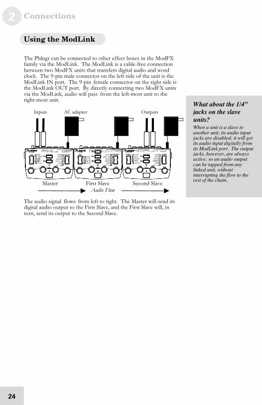
Using the ModLink
The Phlngr can be connected to other effect boxes in the ModFXfamily via the ModLink. The ModLink is a cable-free connectionbetween two ModFX units that transfers digital audio and wordclock. The 9-pin male connector on the left side of the unit is theModLink IN port. The 9-pin female connector on the right side isthe ModLink OUT port. By directly connecting two ModFX unitsvia the ModLink, audio will pass from the left-most unit to theright-most unit.
Inputs AC adapter Outputs
Master First Slave Second Slave
The audio signal flows from left to right. The Master will send itsdigital audio output to the First Slave, and the First Slave will, inturn, send its output to the Second Slave.
What about the 1/4”jacks on the slaveunits?Whe n a u nit is a sla ve to a no th er un it, its a u dio inp utjac ks a r e dis ab le d; it will g etits a ud io in p ut d ig ita lly fro mits Mod Lin k p or t. The o u tp utjac ks , h owev e r, a re alwa y sa ctiv e; so a n a ud io ou tp u tc an b e tap pe d fro m a ny lin ke d u nit, with ou tinter ru p ting th e flo w to th er es t of th e c ha in .
Audio Flow
3 Using the Phlngr
25
This section defines flanging, and explains the functions of thePhlngr’s controls in greater detail. A little technical knowledge willhelp you get the most out of your gear...it’s really pretty simple.
About flanging
In the 1960’s, when engineers had learned how to synchronize twoanalog reel-to-reel tape recorders, someone discovered that if thesame audio was recorded on both recorders, and you deliberatelyslowed one down by dragging your finger on the flange of one ofthe tape reels, a deep comb-filtering effect happened as thewaveforms from each recorder drifted back and forth in time,trying to lock together again. This jet-airplane-like sound becamefamous on recordings by Jimi Hendrix, and the Small Faces.
Today, instead of on tape recorders, the audio is recorded in digitalmemory. It gets played back a few milliseconds later, at a pointthat varies according to the setting of an LFO (Low FrequencyOscillator). This gives you total control of the flanging effect(and, it’s a lot less hassle).
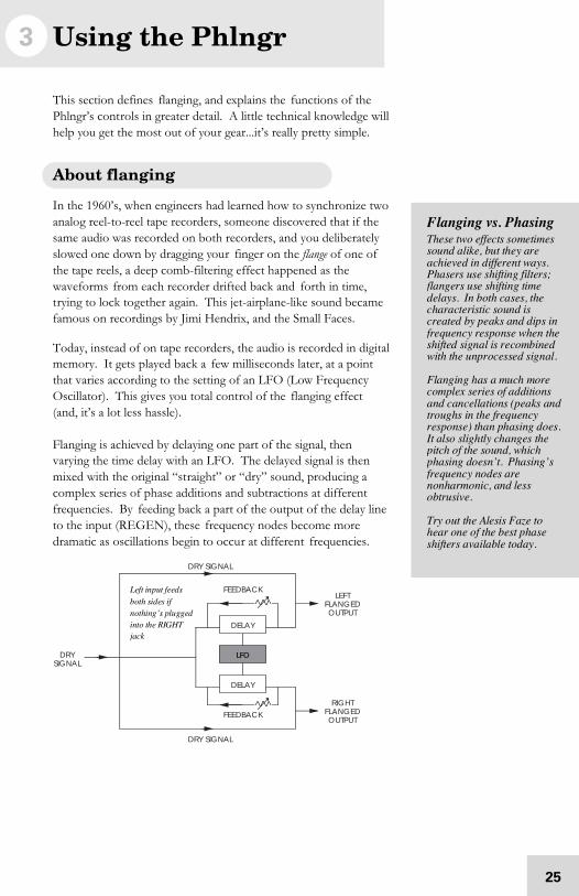
Flanging is achieved by delaying one part of the signal, thenvarying the time delay with an LFO. The delayed signal is thenmixed with the original “straight” or “dry” sound, producing acomplex series of phase additions and subtractions at differentfrequencies. By feeding back a part of the output of the delay lineto the input (REGEN), these frequency nodes become moredramatic as oscillations begin to occur at different frequencies.
Flanging vs. PhasingThe se two effec ts s o me tim es s ou nd a lik e, bu t th e y ar e a ch ie ve d in d iffe re n t wa y s.Pha se rs us e s hiftin g filter s; fla ng er s u se sh iftin g tim ed elay s. I n b oth ca s es , the c ha ra cte ristic so un d isc re ated by p e ak s an d d ip s infre qu en c y re s po ns e whe n the s hifted sign a l is r e co mb ine dwith th e u np r oc es se d s ig n al.
Fla ng in g h as a mu ch mo re c om plex se rie s of a d ditio ns a nd c an c ella tio ns ( p ea ks an dtro ug hs in th e fr eq u en cy r es po ns e ) th a n ph as ing d o es .I t also slig h tly ch a ng es th ep itch o f the so un d, wh ic h p ha sing do es n ’t. Pha sing ’ sfre qu en c y no d es a re n on ha rm o nic, an d le s so btru siv e.
Try o ut th e Ale sis Faz e toh ea r on e o f the b es t p ha s es hifter s a va ila ble tod ay .
LFO
DELAY
DRYSIGNAL
RIGHTFLANGEDOUTPUT
FEEDBACK
DELAY
FEEDBACK
DRY SIGNAL
DRY SIGNAL
LEFTFLANGEDOUTPUT
L ef t in p ut f eed sb ot h si d es i f n ot hi ng ’s pl u gg ed i nt o th e RIGHTj ack
3 Using the Phlngr
26
How the controls work inside the flanger
Picture it this way: there’s a block of audio in delay memoryseveral milliseconds long, always being loaded with new audiofrom the input jacks. A “pointer” picks up this audio at someparticular point in the delay for playback. If the pointer stays inone place, it’s just a static delay line—and when you mix the very-slightly delayed output with the original input, you get a combfilter (phase cancellations at certain frequencies, additions atothers). If you move the pointer back and forth in this blockquickly, the pitch will change: higher as it moves towards the startof the block, lower as it moves towards the end of the block. Thisalso changes the shape of the frequency response, when it’s mixedin with the original signal.
The [DEPTH] control sets how big the “block” of audio is, fromstart to finish. The [RATE] control sets how quickly the playbackpointer runs from the start to the finish of the block and backagain. The Modulation Type (Triangle, Pattern, etc.) sets howsmoothly (or not) the pointer moves through the block. The[CENTER] determines where the pointer starts—beginning, endor center—at the start of a cycle. The [REGEN] control sets howmuch of the output of the pointer is fed back to the input of theblock, and whether that output is in phase (+), or out of phase (-).
Flanging in stereo
Stereo sourceWhen you have a left and right input plugged into the Phlngr, itbehaves like two separate flangers that are synchronized. If apiano goes into the left input, it comes out of the left output,flanged, without mixing with any signal going through the rightchannel (unless the TYPE is set to DEEP MONO, see p. 33).This discrete stereo operation is important for stereo instruments,and if the Phlngr is part of a stereo effects chain (for example,following an Ampliton in autopan mode).
Mono sourceBut, mono sources can be transformed into a pulsating stereosignal when they’re connected to the LEFT/MONO input toachieve a particular dramatic effect. If nothing’s connected to theright input, the LEFT input is automatically sent to both left andright flangers. If you set the TYPE switch to CONTRARYSTEREO or ASYNC STEREO, the different outputs of the twosides will broaden the stereo perspective from any mono source.Especially for listeners on headphones, the result can be quitedramatic.

Using the Phlngr 3
27
What is Tempo Sync?
Flanging occurs over time. Sometimes, you’ll want the rate of theeffect to match the beat of your music instead of being random.For example, you can set the rate so that the flange effectcompletes each cycle once per measure, or to a vibrato-like effectthat happens in sixteenth notes. The TEMPO SYNC feature ofthe Alesis ModFX series not only lets you set a tempo naturally bytapping on the TAP TEMPO button, it can automatically adjust itsspeed slightly relative to the beat of the incoming audio signal,after setting the basic speed using the TAP button.
To use Tempo Sync:
You can set the Phlngr to TEMPO SYNC mode as follows:
1. Press the down side of the [MODULATION] rocker switch toselect the next modulation type.
You can see the type of effect by the LED lit next to the name—forexample, TRIANGLE, HYPER TRI, TRIGGERED and so on.
2. Keep pressing the rocker switch through all the normal modesuntil you enter TEMPO SYNC mode, and then advance to thetype of modulation you want.
Both the Mod Type and TEMPO SYNC LEDs will be lit. Forexample, if you press the down side of the rocker switch when you’re inPATTERN mode, the Phlngr will go to TRIANGLE/TEMPOSYNC mode. At this point, the TAP TEMPO LED will startflashing at the last speed it was set at (or will light solid, indicating thatno tempo has been set since the unit was turned on).
3. Tap the [TAP TEMPO] button several times to set the desiredtempo.
The TAP TEMPO LED will flash in time to the hits. As long asthe [RATE] control is in the center position, the flanging speed willmatch the tempo.
4. If the tempo isn’t quite right, “tap” a steady, discrete beat onany instrument connected to the input. The internal processorwill then synchronize the tapped tempo with the audio input.The processor will make slight alterations to the tempo suchthat it stays synchronized with the beat of the audio input.
To turn Tempo Sync off:Simply press the UP side of the [MODULATION] switchrepeatedly until the Tempo Sync LED goes off, then select themodulation waveform you want.
The RATE knob isdifferent in Temposync modeI n TEMPO S YNC m od e, th eRATE kn o b ac ts as a m ultiplier to the s p ee d s et b yTAP TEMPO, s o y ou c a n’ tg et the te mp o to ch a ng es ligh tly b y a djus tin g th a tk no b. Note tha t ch a ng es to RATE wo n ’t a ffe ct th efla sh in g o f the TEMPO LED .
3 Using the Phlngr
28
Description of Controls
Rate
The [RATE] knob changes the flanging modulation speed.
In normal modulation modes (TEMPO SYNC LED off), turningthe [RATE] knob alters the rate continuously from very slow tovery fast. Turn the knob clockwise for a faster speed, counter-clockwise for a classically-slow sweep.
Rate knob operation in TEMPO SYNC mode
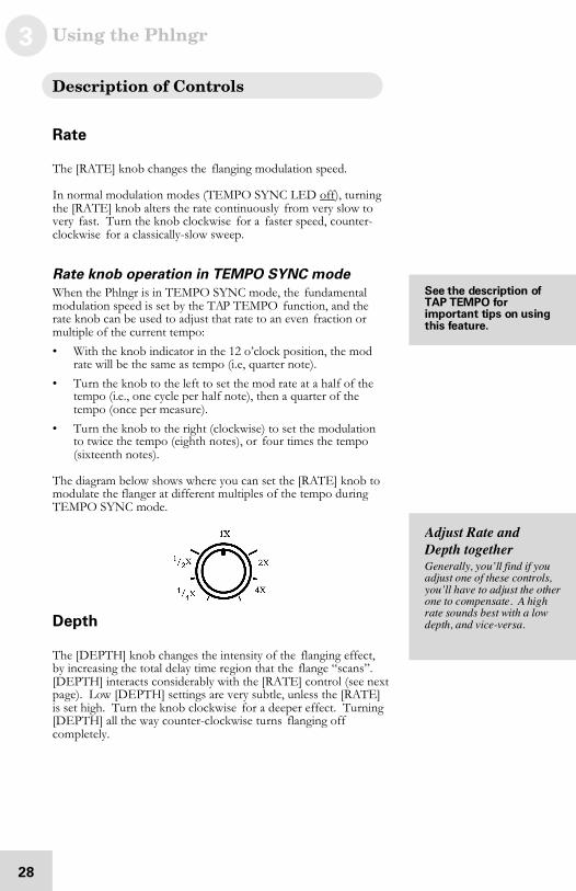
When the Phlngr is in TEMPO SYNC mode, the fundamentalmodulation speed is set by the TAP TEMPO function, and therate knob can be used to adjust that rate to an even fraction ormultiple of the current tempo:
• With the knob indicator in the 12 o’clock position, the modrate will be the same as tempo (i.e, quarter note).
• Turn the knob to the left to set the mod rate at a half of thetempo (i.e., one cycle per half note), then a quarter of thetempo (once per measure).
• Turn the knob to the right (clockwise) to set the modulationto twice the tempo (eighth notes), or four times the tempo(sixteenth notes).
The diagram below shows where you can set the [RATE] knob tomodulate the flanger at different multiples of the tempo duringTEMPO SYNC mode.
Depth
The [DEPTH] knob changes the intensity of the flanging effect,by increasing the total delay time region that the flange “scans”.[DEPTH] interacts considerably with the [RATE] control (see nextpage). Low [DEPTH] settings are very subtle, unless the [RATE]is set high. Turn the knob clockwise for a deeper effect. Turning[DEPTH] all the way counter-clockwise turns flanging offcompletely.
Se e t he de sc r ip t i on of T A P T EM P O f o r i mp or t a n t ti p s on u s in gt hi s f e a t u r e .
Adjust Rate andDepth togetherG en er ally, y o u’ ll find if y ou a djus t o ne o f the se co ntr ols,y ou ’ll h av e to ad ju s t th e o th er o ne to c om pe n sa te . A hig hr ate so u nd s b es t with a lowd ep th , a nd v ice -v er s a.
Using the Phlngr 3
29
Center
The [CENTER] knob changes the center frequency of thePhlngr’s effect. Its effect varies depending on the mode andspeed, but in pitch terms, when the [CENTER] knob is at the 12o’clock position, you’ll hear the pitch oscillates up and down fromthe center frequency. When it’s turned full counter-clockwise, itoscillates only in one direction, and at full clockwise it oscillatesonly in the other direction.
Regen
The [REGEN] knob changes the amount of positive or negativefeedback (how much output of the flanger is fed back to theflanger’s input).
• For no feedback of the flanged signal back to the input of theflanger, leave this knob in the center “12 o’clock” position.
• To increase positive feedback, turn [REGEN] clockwise fromcenter.
• For negative feedback, turn [REGEN] counter-clockwisefrom center.
To he ar ho w CEN TERwor ks f o r y ours elf , s et a d ee p, m e dium - ra te flan ge with a Trian g le s ou r ce ,m ay be with s o me REG ENa dd ed . Tr y d iffe re n t se tting so f th e [ CENTER] k no b , an d tap the [RES ET MO D] s witc h.
3 Using the Phlngr
30
Modulation Select Switch
The up/down rocker switch on the right side of the unit selects themodulation source for the flanger. The LEDs next to the switchlight up to indicate the current mode. There are five kinds ofmodulation available, explained below. The rocker switch alsoselects TEMPO SYNC mode, as explained earlier.
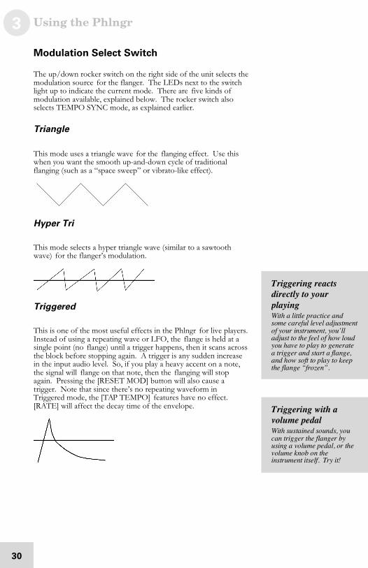
Triangle
This mode uses a triangle wave for the flanging effect. Use thiswhen you want the smooth up-and-down cycle of traditionalflanging (such as a “space sweep” or vibrato-like effect).
Hyper Tri
This mode selects a hyper triangle wave (similar to a sawtoothwave) for the flanger’s modulation.
Triggered
This is one of the most useful effects in the Phlngr for live players.Instead of using a repeating wave or LFO, the flange is held at asingle point (no flange) until a trigger happens, then it scans acrossthe block before stopping again. A trigger is any sudden increasein the input audio level. So, if you play a heavy accent on a note,the signal will flange on that note, then the flanging will stopagain. Pressing the [RESET MOD] button will also cause atrigger. Note that since there’s no repeating waveform inTriggered mode, the [TAP TEMPO] features have no effect.[RATE] will affect the decay time of the envelope. Triggering with a
volume pedalWith su s ta in e d so un d s, y o uc an trig ge r the fla ng er by u sing a vo lu m e pe da l, or th ev olum e k no b o n th eins tr um e nt itse lf. Tr y it!
Triggering reactsdirectly to yourplayingWith a little p ra ctice a n ds om e ca r eful le ve l a djus tme nto f yo ur in str um en t, yo u’ lla djus t to th e fee l o f ho w lou dy ou h av e to p la y to ge ne r atea trigg e r an d s ta rt a fla ng e,a nd h ow so ft to p la y to k ee pthe fla n ge “fro ze n”.
Using the Phlngr 3
31
Uncertainty
This mode randomly generates a continually altering waveform forthe flange modulation, changing direction at various points duringthe cycle.
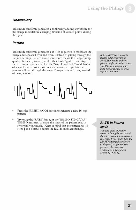
Pattern
This mode randomly generates a 16-step sequence to modulate theflange and repeats it over and over. Instead of gliding through thefrequency range, Pattern mode sometimes makes the flanger jumpquickly from step to step, while other levels “glide” from step tostep. It sounds somewhat like the “sample and hold” modulationof a synchronized oscillator on a synthesizer, except that thepattern will step through the same 16 steps over and over, insteadof being random.
• Press the [RESET MOD] button to generate a new 16-steppattern.
• Try using the [RATE] knob, or the TEMPO SYNC/TAPTEMPO features, to make the steps of the pattern play insync with your music. Keep in mind that the pattern has 16steps per 4 beats, so adjust the RATE knob accordingly.
I f th e [ REGEN] co ntr ol is tur ne d a ll th e wa y u p in PATTERN mo de an d yo u p la y a s in gle , su sta in ed to ne ,y ou ’ll h ea r a s am ple -a nd - h old- lik e se q ue nc e o f to n es a ga in st th at to ne .
RATE in PatternmodeYou c an th in k o f Pa tte rn m od e as be in g 4 x th e r ate o fthe o th e r mo d ulatio n s ou r ce s.I n Te mp o S yn c m od e, tu rn th e[ RATE] k no b full clo ck wis e( 1/4 sp e ed ) to ge t o ne s tep p er b ea t, th e s am e a sTrian gle a t a 1 2 o’ c lo ck s etting of [ RATE] .
3 Using the Phlngr
32
TYPE Rocker Switch
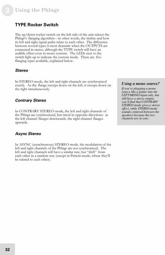
The up/down rocker switch on the left side of the unit selects thePhlngr’s flanging algorithm—in other words, the timbre and howits left and right signal paths relate to each other. The differencebetween several types is most dramatic when the OUTPUTS areconnected in stereo, although the TYPE switch will have anaudible effect even in mono systems. The LEDs next to theswitch light up to indicate the current mode. There are fiveflanging types available, explained below.
Stereo
In STEREO mode, the left and right channels are synchronizedexactly. As the flange sweeps down on the left, it sweeps down onthe right simultaneously.
Contrary Stereo
In CONTRARY STEREO mode, the left and right channels ofthe Phlngr are synchronized, but travel in opposite directions: asthe left channel flanges downwards, the right channel flangesupwards.
Async Stereo
In ASYNC (asynchronous) STEREO mode, the modulation of theleft and right channels of the Phlngr are not synchronized. Theleft and right channels will have a similar rate, but “drift” fromeach other in a random way (except in Pattern mode, where they’llbe related to each other).
Using a mono source?I f yo u’ r e plu gg in g a m on o s ou rc e lik e a g uita r into the LEFT/MO NO in p ut o nly , bu ts till h a ve a ster eo ou tp u t,y ou ’ll fin d tha t CO NTRARYS TEREO m od e g iv es a ster e oe ffec t, wh ile S TEREO m od e s ou nd s c en te r ed b etwee n the s pe ak er s b ec a us e th e two c ha nn els a re in s yn c .
Using the Phlngr 3
33
Through Zero
This mode delays the input signal to better simulate tape flanging.When flanging was done using two tape machines, it was possiblefor one to be behind the other, catch up and then go past theother. This is called “passing through zero”, the “zero” pointbeing when both signals were in perfect sync. As the flange passesclose to zero, there’s a point where the sound almost vanishescompletely as the two signals are out of phase.
Since the Phlngr is digitally simulating the flanging effect (andnormally can’t “go past” the input signal coming in in real time),this mode delays the unprocessed “dry” signal by as much as 12milliseconds. This small delay is virtually undetectable to the ear,but it allows the flanged signal to move “behind” the dry signal asit cycles.
Deep Mono
If you’ve cranked up the [DEPTH] control all the way, but stillaren’t getting the dramatic flange effect you’re looking for, tryDEEP MONO. This mode sums the left and right channelstogether, so it can use both sides of the Phlngr’s digital memory toprovide a block of sound to scan that’s twice as long as in any ofthe previous modes. Even at slow [RATE] settings, there can be adramatic pitch-shifting effect in this mode, so it’s particularlyuseful when you want a slow flange. Usually, you’ll need to reducethe [DEPTH] control in this mode.
If you’re using aneffect send...I n Th ro u gh Ze ro m od e , mu tea ny “dr y ” sig na l pa ththr ou gh th e c on so le . Le t the Phlng r h an dle the we t/dr y m ix . O the rwise , yo u ’ll h ea r afix ed h o llow kind o f s ou n dr es ultin g fr o m th e d elay of the d ry s ig n al th ro ug h the Ph ln gr m ix in g with the u nd elay e ds ig na l.

3 Using the Phlngr
34
Reset Mod
Press this button to reset the phase of the flanger modulationsource as follows:
• In TRIANGLE, HYPER TRI, and UNCERTAINTY modes,press [RESET MOD] to start the wave from the beginning ofits phase.
The “starting point” of the wave in digital memory is determined by thesetting of the [CENTER] control
• In TRIGGERED mode press this button to generate a triggerfor the modulation (momentarily flanging across the memory,then stopping).
• In PATTERN mode press this button to generate a new 16-step pattern.
Using the Phlngr 3
35
Tap Tempo
This button affects the speed of the effect whenever the[MODULATION] switch is set to a TEMPO SYNC mode. Atany time you can tap this button along with the music to set a newtempo. The Tap Tempo light will flash at the current tempo.
Tap Tempo technique
For a reliable tempo setting, make from four to eight taps in a rowat a consistent speed, especially if you’re changing the tempodrastically. Watch the flashing of the light to see the currenttempo of the Phlngr.
Adjusting tempo with audio input
After the basic tempo has been set using the [TAP TEMPO]button, it is possible to make small adjustments to the tempo viathe audio input. You do this by “tapping” on the instrument(playing sharp chords, or beats, without sustain or notesinbetween) at almost the same speed as the Phlngr’s tempo LED,or by slightly changing the speed of a drum machine feeding theinputs. The Phlngr will automatically follow the beat from acomplex musical input, as long as it is reasonably close to theoriginal “tapped” tempo (it can adjust up or down about 5 beatsper minute from the tempo set on the [TAP TEMPO] button).
How Tap Tempo works with Tempo Sync andthe Rate knobs
When TEMPO SYNC mode is enabled, the rate of the modulationwill be based on the tempo currently being flashed, multiplied bythe position of its [RATE] knob: when it’s in the middle position(around “12 o’clock”), the speed of the triangle, hyper tri oruncertainty wave, or the pattern, will be the same as the tempo.See the earlier descriptions of the [RATE] knob and Tempo Syncfor more information.
To get fastmodulations...it is n’ t n ec e ss ar y to ta p a t ah ig h sp e ed if y ou wa nt th ee ffec t to mo d ulate a t eig hth or s ix te en th no tes . J u st ta p on the q ua rter - no te be at, the ntur n th e [ RATE] k no b to the r ig ht to d ou b le o r q ua dr u plethe s pe e d ma d e by Ta pTem po .
3 Using the Phlngr
36
Bypass
This button sends the signal directly from the input to the outputwithout any effect. Press [BYPASS] to check the sound of thesource without any effect from the Phlngr. When the redBYPASS LED is lit, the flanging effect is off. The Bypassfunction can also be activated by a footswitch.
Since the Phlngr is a digital effect, signal always passes through thedigital A/D–D/A conversion process, so that digital signal willflow through to other effects in a ModLink chain even when[BYPASS] is on. So, unlike old analog effects, this is not a“hardwire” bypass switch—the Phlngr must be powered on topass signal through, even in bypass mode. Similarly, the [TRIM]control is always active, since it’s an analog control regulating thelevel feeding the analog-to-digital converters.
Using the Foot Switch
If you need to bypass the effect totally but your hands aren’t free,simply connect any momentary footswitch (such as those used forkeyboard sustain pedals, either NC normally closed or NOnormally open) to the [FOOT SWITCH] jack on the rear panel.The footswitch will turn the BYPASS LED on and off.
4 Sample Settings
37
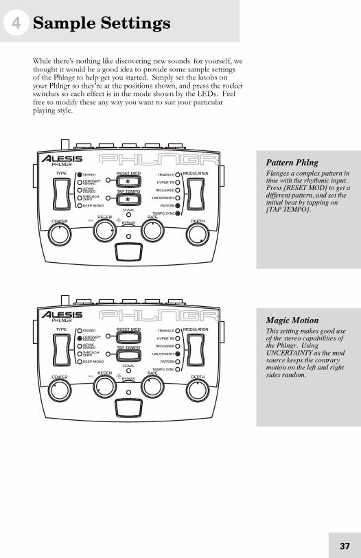
While there’s nothing like discovering new sounds for yourself, wethought it would be a good idea to provide some sample settingsof the Phlngr to help get you started. Simply set the knobs onyour Phlngr so they’re at the positions shown, and press the rockerswitches so each effect is in the mode shown by the LEDs. Feelfree to modify these any way you want to suit your particularplaying style.
Pattern PhlngFla ng es a co m plex p a tter n intim e with th e r hy th m ic in pu t.Pre ss [ RES ET MO D] to g et ad iffe re n t pa tte rn , a nd s e t th einitial be at by tap p in g o n[ TAP TEMPO ].
Magic MotionThis se tting ma ke s g oo d u se o f th e s te re o c ap ab ilitie s ofthe Phlng r. U sin gU NCERTAI NTY a s th e m od s ou rc e k ee ps th e co n tr ar y m otio n o n th e left a nd r igh ts id es r a nd om .
4 Sample Settings
38
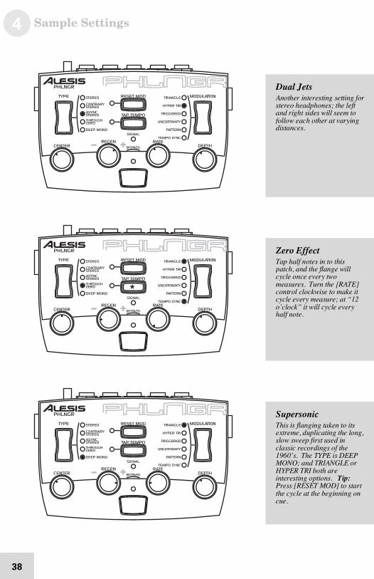
Zero EffectTap h alf n ote s in to this p atch , a nd th e flan g e willc yc le o n ce e v er y two m ea su re s . Tu rn the [RATE]c on tr ol cloc k wise to m ak e itc yc le e v er y m ea su re ; a t “12 o ’c lo ck ” it will cy c le e v er yh alf no te.
Dual JetsAno th er in te r es ting se tting for s te re o h ea dp h on es ; the le fta nd r ig h t sid es will s ee m tofollo w e ac h o th er a t v ar y in gd is ta nc e s.
SupersonicThis is flan g in g ta k en to its e xtre me , d up lic atin g the lo ng ,s lo w swe ep firs t us e d in c la ss ic re co r ding s o f th e 1 96 0’ s. The TYPE is D EEPMONO; a n d TRI ANGLE o rH YPER TRI bo th ar einter es tin g o ptio ns . Tip :Pre ss [ RES ET MO D] to s ta r tthe c yc le at th e be g in nin g on c ue .
Sample Settings 4
39
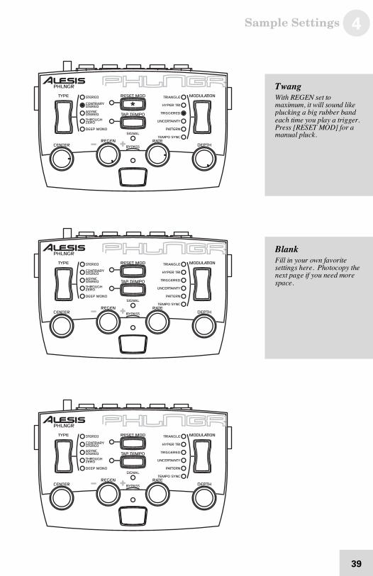
BlankFill in yo ur own fa v or ite s etting s h er e . Pho toc op y the n ex t pa g e if yo u ne e d mo r es pa ce .
TwangWith REG EN s e t to m ax im um , it will so u nd like p lu ck in g a b ig ru bb e r ba n de ac h tim e yo u p la y a trig ge r.Pre ss [ RES ET MO D] fo r am an ua l p lu ck .
4 Sample Settings
40
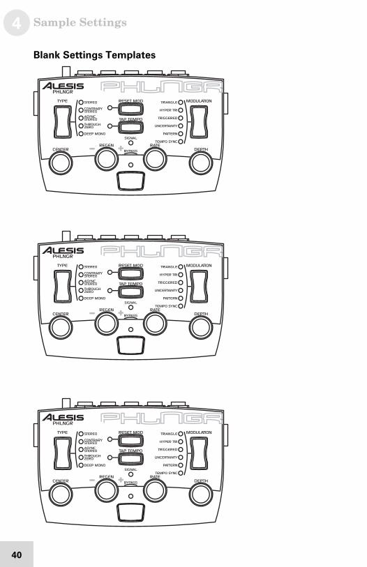
Blank Settings Templates
5 Troubleshooting
41
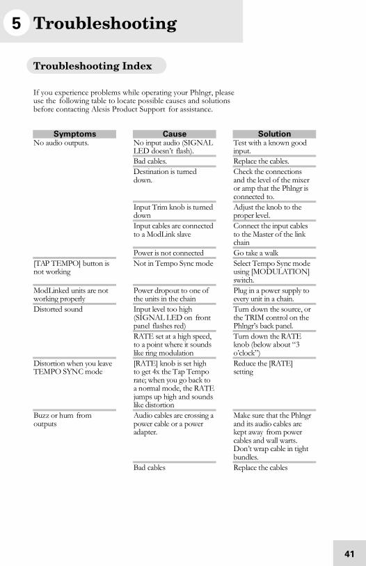
Troubleshooting Index
If you experience problems while operating your Phlngr, pleaseuse the following table to locate possible causes and solutionsbefore contacting Alesis Product Support for assistance.
Symptoms Cause SolutionNo audio output s. No input audio (SIGNAL
LED doesn ’t flash).Test with a known goodinp ut.
Bad cables. Rep lace t he cab les.Destination is turneddown.
Check the connectionsand the level of th e mixeror amp th at the Phlngr iscon nected to.
Inp ut Trim knob is tu rneddown
Adjust th e knob to th epro per level.
Inp ut cab les are conn ectedto a ModLink slave
Con nect t he inp ut cab lesto the Master o f the linkchain
Power is no t conn ected Go take a walk[TAP T EMPO] button isnot working
Not in Tempo Sync mod e Select Tempo Sync mod eusing [MO DULATIO N]switch.
Mod Linked units are n otworking p roperly
Power dropo ut to one of the units in th e chain
Plug in a power supply toevery unit in a chain.
Inp ut level too h igh(SIGNAL LED on fro ntpan el flashes red)
Turn down the so urce, orthe TRIM cont rol on th ePhlngr’s back p anel.
Distorted sound
RATE set at a hig h speed,to a poin t where it soundslike ring modulation
Turn down the RATEkno b (below about “ 3o’clock”)
Distortio n when you leaveTEM PO SYN C mode
[RATE] knob is set highto get 4x the T ap Tem porat e; when you go back toa n ormal mode, the RATEjum ps up high and soundslike dist ortion
Red uce th e [RATE]set ting
Buz z or h um fro mout puts
Aud io cab les are crossing apower cable or a poweradapter.
Make sure that t he Phlngrand its audio cables arekep t away fro m powercab les an d wall warts.Don ’t wrap cable in t ightbun dles.
Bad cables Rep lace t he cab les

5 Troubleshooting
42
Symptoms Cause Solution
Pro blem w ith th e source Try bypassing t he Phlngrby connecting t he inp utcab les to the o utput cablesand see if the problemrem ains.
AC hum Gro und lo op Place all equip ment in thestudio on a com mongro und (see next page)
Troubleshooting 5
43
Avoiding ground loop noise
In today’s studio, where it seems every piece of equipment has itsown computer chip inside, there are many opportunities forground loop problems to occur. These show up as hums, buzzesor sometimes radio reception and can occur if a piece ofequipment "sees" two or more different paths to ground. Whilethere are methods to virtually eliminate ground loops and strayradio frequency interference, most of the professional methods areexpensive and involve installing a separate power source just forthe sound system. Alternatively, here are some helpful hints thatprofessional studio installers use to keep those stray hums andbuzzes to a minimum.
KEEP ALL ELECTRONICS OF THE SOUNDSYSTEM ON THE SAME AC ELECTRICALCIRCUIT.
Most stray hums and buzzes happen as a result of different partsof the sound system being plugged into outlets of different ACcircuits. If any noise generating devices such as air conditioners,refrigerators, neon lights, etc., are already plugged into one of thesecircuits, you then have a perfect condition for stray buzzes. Sincemost electronic devices of a sound system don’t require a lot ofcurrent (except for power amplifiers), it’s usually safe to run amulti-outlet box or two from a SINGLE wall outlet and plug in allof the components of your system there.
KEEP AUDIO WIRING AS FAR AWAY FROM ACWIRING AS POSSIBLE.
Many hums come from audio cabling being too near AC wiring orpower transformers. If a hum occurs, try moving the audio wiringaround to see if the hum ceases or diminishes. If it’s not possibleto separate the audio and AC wiring in some instances, make surethat the audio wires don’t run parallel to any AC wire (they shouldonly cross at right angles, if possible).
TO ELIMINATE HUM IF THE ABOVE HAS FAILED:
1. Disconnect the power from all outboard devices andtape machines except for the Phlngr, the mixer andcontrol room monitor power amp.
2. Plug in each tape machine and outboard effects deviceone at a time. If possible, flip the polarity of the plug ofeach device (turn it around in the socket) until thequietest position is found.
3. Make sure that all of the audio cables are in goodworking order. Cables with a detached ground wire willcause a very loud hum!!
5 Troubleshooting
44
4. Keep all cables as short as possible, especially inunbalanced circuits.
If the basic experiments don’t uncover the source of the problem,consult your dealer or technician trained in proper studiogrounding techniques. In some cases, a "star grounding" schememust be used, with the mixer at the center of the star providing theshield ground on telescoping shields, which do NOT connect tothe chassis ground of other equipment in the system.
Line conditioners and spike protectors
Although the Phlngr is designed to tolerate typical voltagevariations, in today’s world the voltage coming from the AC linemay contain spikes or transients. These can cause audible noises,and they can stress your gear and, over time, possibly cause afailure. There are three main ways to protect against this, listed inascending order of cost and complexity:
• Line spike/surge protectors. Relatively inexpensive,these are designed to protect against strong surges andspikes, acting somewhat like fuses in that they need tobe replaced if they’ve been hit by an extremely strongspike.
• Line filters. These generally combine spike/surgeprotection with filters that remove some line noise(dimmer hash, transients from other appliances, etc.). Agood example is the Isobar™ series from Tripp Lite.
• Uninterruptible power supply (UPS). This is themost sophisticated option. A UPS provides power evenif the AC power line fails completely. Intended forcomputer applications, a UPS allows you to complete anorderly shutdown of a computer system in the event of apower outage. In addition, the isolation it providesfrom the power line minimizes all forms ofinterference—spikes, noise, etc.
Troubleshooting 5
45
Care and Maintenance
Cleaning
Disconnect the AC cord, then use a damp cloth to clean thePhlngr’s metal and plastic surfaces. For heavy dirt, use a non-abrasive household cleaner such as Formula 409™ or Fantastik™.DO NOT SPRAY THE CLEANER DIRECTLY ONTO THEFRONT OF THE UNIT AS IT MAY DESTROY THELUBRICANTS USED IN THE SWITCHES AND CONTROLS!Spray onto a cloth, then use cloth to clean the unit.
Refer all servicing to Alesis
We believe that the Phlngr is one of the best signal processors thatcan be made using current technology, and should provide years oftrouble-free use. However, should problems occur, DO NOTattempt to service the unit yourself unless you have training andexperience. Service on this product should be performed byqualified technicians only. NO USER-SERVICEABLE PARTSINSIDE.
5 Troubleshooting
46
Obtaining repair service
Before contacting Alesis, check over all your connections, andmake sure you’ve read the manual.
Customers in the USA and Canada:
If the problem persists, contact Alesis and request the ProductSupport department. Make sure you have the unit’s serial numberwith you. Talk the problem over with one of our technicians; ifnecessary, you will be given a return order (RO) number andinstructions on how to return the unit. All units must be shippedprepaid and COD shipments will not be accepted.
For prompt service, indicate the RO number on the shipping label.Units without an RO will not be accepted. If you do not havethe original packing, ship the unit in a sturdy carton, with shock-absorbing materials such as Styrofoam pellets (the kind withoutCFCs, please) or "bubble-pack" surrounding the unit. Shippingdamage caused by inadequate packing is not covered by the Alesiswarranty.
Tape a note to the top of the unit describing the problem. Includeyour name and a phone number where Alesis can contact you ifnecessary, as well as instructions on where you want the productreturned. Alesis will pay for standard one-way shipping back toyou on any repair covered under the terms of this warranty. Next-day service is available for a surcharge. Field repairs are notauthorized during the warranty period, and repair attempts byunqualified personnel may invalidate the warranty.
Customers outside the USA and Canada:
Contact your local Alesis distributor for any warranty assistance.The Alesis Limited Warranty applies only to products sold to usersin the USA and Canada. Customers outside of the USA andCanada are not covered by this Limited Warranty and may or maynot be covered by an independent distributor warranty in thecountry of sale. Do not return products to the factory unless youhave been given specific instructions to do so.
Specifications
47
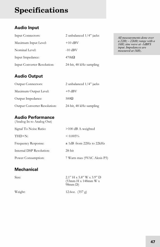
Audio Input
Input Connectors: 2 unbalanced 1/4” jacks
Maximum Input Level: +10 dBV
Nominal Level: -10 dBV
Input Impedance: 470kΩ
Input Converter Resolution: 24-bit, 48 kHz sampling
Audio Output
Output Connectors: 2 unbalanced 1/4” jacks
Maximum Output Level: +9 dBV
Output Impedance: 500Ω
Output Converter Resolution: 24-bit, 48 kHz sampling
Audio Performance(Analog In to Analog Out)
Signal To Noise Ratio: >100 dB A-weighted
THD+N: < 0.005%
Frequency Response: ± 1dB from 22Hz to 22kHz
Internal DSP Resolution: 28-bit
Power Consumption: 7 Watts max (9VAC Alesis P3)
Mechanical
Size: 2.1” H x 5.8” W x 3.9” D(53mm H x 148mm W x98mm D)
Weight: 12.6oz. (357 g)
All m ea s ur em e nts do n e ov e ra 2 2H z – 2 2k H z ra ng e with a 1 kH z sin e wa v e at - 1 dBFS inp ut. I mp ed an c es a r em ea su re d a t 1 kH z.

6 Specifications
48
This page intentionally left blank.
Index
49
amplifier, 21ASYNC STEREO, 26, 32BYPASS, 16, 35
with foot switch, 35cables, 22CENTER, 16, 29
effect on RESET MOD, 34CONTRARY STEREO, 26, 32Deep Mono, 33DEPTH, 16, 28
interaction with RATE, 29digital converters, 4, 35, 47doppler effect, 29DSP, 4, 47Effect Send/Return, 20feedback
controlled by REGENknob, 29
Flangingdefined, 25stereo, 26
FOOT SWITCH, 16, 35Ground Loop, 43grounding, 7guitar, 18Hums and buzzes, 43Hyper Tri, 30INPUTS, 15INPUTS and OUTPUTS, 16Insert Cables, 18levels, 22LFO, 25mixing console
hookup, 19
ModLink, 4, 5, 16, 23MODULATION SELECT switch, 16, 30Mono
sources, 26OUTPUTS, 15
on ModLink slave units, 23Pattern, 31Phasing, 25power adapter, 16, 17Power cable, 7Rack mounting, 17radio/TV interference, 9RATE, 16, 28REGEN, 16, 25, 29Reset Mod, 16, 34
in Triggered Mode, 30Safety, 7SIGNAL LED, 15, 16, 18, 22stereo, 18
sources, 26TYPE mode, 32
Tap Tempo, 16, 27, 34Tempo Sync, 27
effect on RATE knob, 28Through Zero, 33transformers, 22Triangle, 30Triggered, 30
by RESET MOD, 34TRIM, 15, 16, 18
active in bypass mode, 35TYPE, 16, 32Uncertainty, 31XLR, 22

Warranty / Contact Alesis
50
Alesis Limited Warranty
ALESIS CORPORATION ("ALESIS") warrants this product to be free of defectsin material and workmanship for a period of one (1) year for parts and for a period ofone (1) year for labor from the date of original retail purchase. This warranty isenforceable only by the original retail purchaser and cannot be transferred or assigned.For the most effective service, the purchaser should re gister the purchase on theALESIS website at http://www.alesis.com/support/warranty.htm.During the warranty period ALESIS shall, at its sole and absolute option, either repairor replace free of charge any product that proves to be defective on inspection byALESIS or its authorized service representative. In all cases disputes concerning thiswarranty shall be resolved as prescribed by law.To obtain warranty service, the purchaser must first call or write ALESIS at theaddress and telephone number available on the Alesis Website to obtain a ReturnAuthorization Number and inst ructions concerning where to return the unit forservice. All inquiries must be accompanied by a description of the problem. Allauthorized returns must be sent to ALESIS or an authorized ALESIS repair facilitypostage prepaid, insured and properly packaged. Proof of purchase must bepresented in the form of a bill of sale, canceled check or some other positive proofthat the product is within the warranty period. ALESIS reserves the right to updateany unit returned for repair. ALESIS reserves the right to change or improve designof the product at any time without prior notice.This warranty does not cover claims for damage due to abuse, neglect, alteration orattempted repair by unauthorized personnel, and is limited to failures arising duringnormal use that are due to defects in material or workmanship in the product.THE ABOVE WARRANTIES ARE IN LIEU OF ANY OTHERWARRANTIES OR REPRESENTATIONS WHETHER EXPRESS ORIMPLIED OR OTHERWISE, WITH RESPECT TO THE PRODUCT, ANDSPECIFICALLY EXCLUDE ANY IMPLIED WARRANTIES OF FITNESSFOR A PARTICULAR PURPOSE OR MERCHANTABILITY OR OTHERIMPLIED WARRANTIES. Some states do not allow limitations on how long animplied warranty lasts, so the above limitation may not apply to you.IN NO EVENT WILL ALESIS BE LIABLE FOR INCIDENTAL,CONSEQUENTIAL, INDIRECT OR OTHER DAMAGES RESULTINGFROM THE BREACH OF ANY EXPRESS OR IMPLIED WARRANTY,INCLUDING, AMONG OTHER THINGS, DAMAGE TO PROPERTY,DAMAGE BASED ON INCONVENIENCE OR ON LOSS OF USE OF THEPRODUCT, AND, TO THE EXTENT PERMITTED BY LAW, DAMAGESFOR PERSONAL INJURY. Some states do not allow the exclusion or limitation ofincidental or consequential damages, so the above limitation or exclusion may notapply to you.THIS CONTRACT SHALL BE GOVERNED BY THE INTERNAL LAWSOF THE STATE OF CALIFORNIA WITHOUT REFERENCE TOCONFLICTS OF LAWS. This warranty gives you specific le gal rights, and you mayalso have other rights required by law which vary from state to state.This warranty only applies to products sold to purchasers in the United States ofAmerica or Canada. The terms of this warranty and any obligations of Alesis underthis warranty shall apply only within the country of sale. Without limiting theforegoing, repairs under this warranty shall be made only by a duly authorized Alesisservice representative in the count ry of sale. For warranty information in all othercount ries please refer to your local distributor.
For more effectiveservice and productupdate notices, pleaseregister your Phlngronline at:http://www.alesis.com/support/warranty.htm

Warranty/Contact Information
51
Alesis Contact Information
Alesis Studio ElectronicsLos Angeles, CA USA
E-mail: [email protected]: http://www.alesis.com
Alesis Phlngr Reference ManualRevision 1.0 by Alex Souppa & Dan Tinen
Copyright 2002, Alesis. All rights reservedReproduction in whole or in part is prohibited. Specificationssubject to change without notice.
All trademarks are the property of their respective holders.
7-51-0114-A8/2002